AT-3535 - Tripod Oben - Free user manual and instructions
Find the device manual for free AT-3535 Oben in PDF.


User questions about AT-3535 Oben
0 question about this device. Answer the ones you know or ask your own.
Ask a new question about this device
Download the instructions for your Tripod in PDF format for free! Find your manual AT-3535 - Oben and take your electronic device back in hand. On this page are published all the documents necessary for the use of your device. AT-3535 by Oben.
USER MANUAL AT-3535 Oben
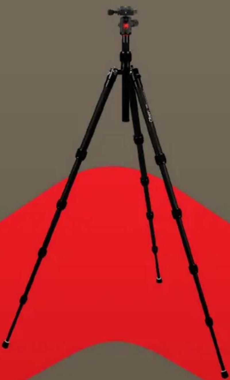
3500 Series Tripod Kit
natural_image
Black tripod with tripod-mounted camera on top, set against a red abstract background (no text or symbols visible)You're on steady ground®
Thank you for choosing Oben!
This versatile and durable Oben tripod and ballhead is a compact and lightweight kit that sets up quickly, folds up neatly into its own carry bag, and offers a variety of options ideal for the photographer on the go.
The Oben AT/CT-3500 Series 5-section tripod features twist locks for fast and effortless height adjustment. Each leg can be positioned independently at three locking angles to ensure stable support when shooting on uneven terrain. Integrated spiked feet beneath the nonslip rubber feet provide stability on soft ground, grass, or sand. The adjustable center column is equipped with a spring-loaded weight hook for added steadiness in windy conditions.
This tripod boasts several options for low-angle shooting. A low-angle center column is included with the tripod for mounting a camera close to the ground. The tripod's standard center column is also reversible for extremely close proximity to the surface. For additional adaptability, one leg of the tripod can be removed and used as a completely functional monopod.
Oben's BE-Series dual-action or BZ-Series triple-action ballhead is included with the tripod to provide smooth and effortless operation. It features two locks that provide independent adjustment of the ball and panoramic base. Integrated bubble levels ensure accurate camera alignment with the horizon. An Arca-type quick-release plate allows for mounting and dismounting the camera quickly and effortlessly.
Please read through this entire manual before using the AT/CT-3500 Series tripod and the BE/BZ-Series ballhead.
Note: Images are for illustrative purposes only. Actual product may vary.
Key Features 4-7
Ballhead Operation 8-14
The Tripod Mounting Screw 8
Mounting the Ballhead 9
Main Locking Knob Operation 11
Mounting the Quick-Release Plate to the Camera 9
Mounting the Camera and Quick-Release Plate to the Ballhead 10
Tension Knob (BZ-217T & BZ-226T only) 12
Adjusting the Friction (BZ-217T & BZ-226T only) 13
Panoramic Base 14
Tripod Operation 14-21
Leg Length Adjustment 14
Leg Angle Adjustment 15
Center-Column Adjustment 15
Low-Angle Setup 16-18
Counterweight 19
Spiked Feet 20
Integrated Monopod 20
Folding Legs 21
Specifications 22
Warnings 23
text_image
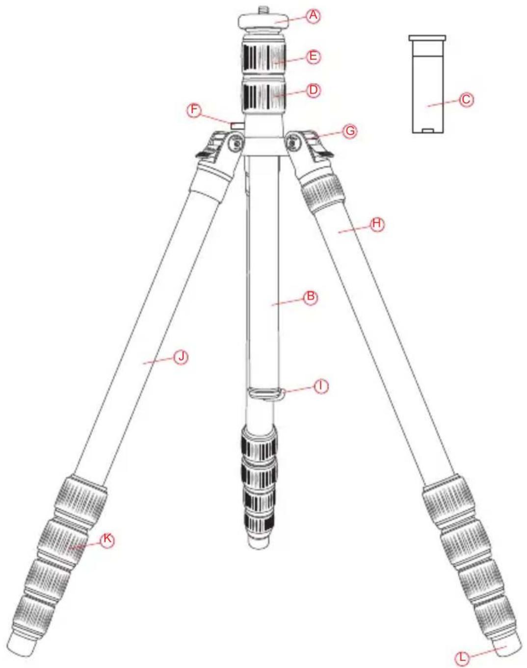
A E D F G C H B I J K LA Baseplate with Dual 3/8 -16 and 1/4-20 head mounting screw
Two-piece center column (AT/CT-3535) One-piece center column (AT/CT-3565 and AT/CT-3586)
© Low-angle center column
Center-column locking collar
Center-column twist lock (AT/CT-3535)
F Strap mount
G Leg angle adjustment lock
Integrated monopod
Retractable and removable weight hook
180° folding legs
Leg adjustment twist locks
Integrated spiked feet
Also Included: Carry bag Carry bag strap Low angle column Hex keys ( × 2)
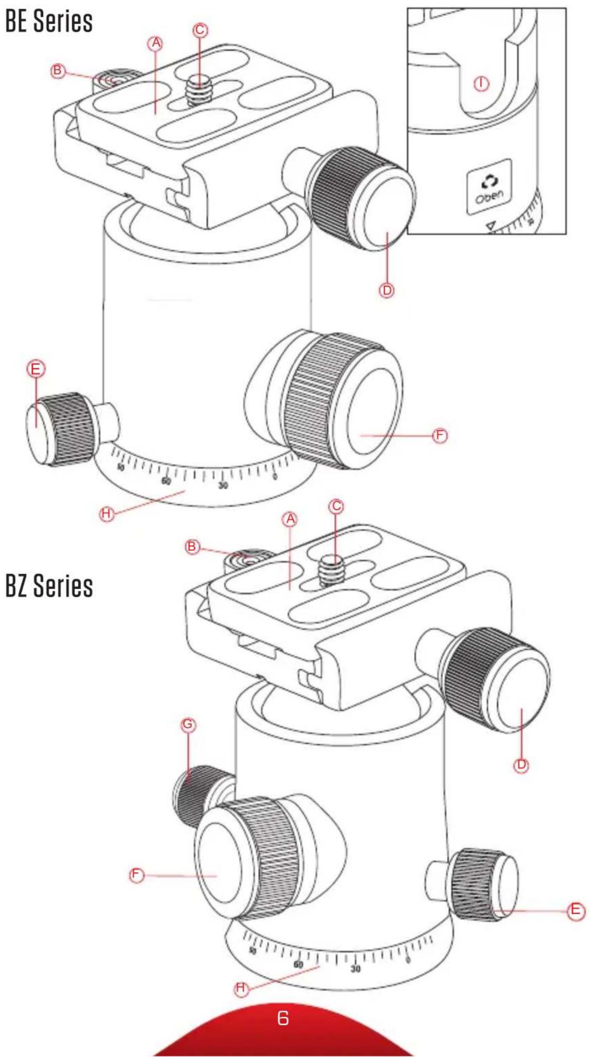
(A) Quick-release plate
B Bubble level
© 1/4-20 mounting screw
D Quick-release knob
E Pan knob
F Main locking knob
① 90° groove
G Tension knob (BZ-217T & BZ-226T)
Panoramic base with 360° markings
Ballhead Operation
The AT/CT-3500 Series tripod and BE/BZ Series ballhead come assembled. During normal operation, the ballhead will occasionally have to be removed in order to make adjustments to the tripod.
THE TRIPOD MOUNTING SCREW
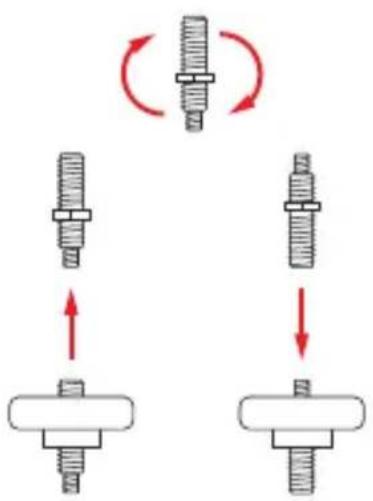
The tripod includes a mounting screw with a 3/8-16 thread on one end and a 1/4-20 thread on the other, allowing you to mount a tripod head with either size mounting socket.
To switch between the two mounting screw sizes, do the following:
-
Unscrew the ballhead, and use the included hex key to loosen the set screw that is next to the mounting screw.
-
Unscrew the baseplate from the tripod.
-
Lift the screw out, reverse it, and insert the opposite end back into the baseplate.
-
Replace the baseplate by screwing it back into the tripod and tightening the set screw with the hex key.
text_image
Diagram illustrating screw thread positioning and rotation, showing two configurations with arrows indicating direction of movement.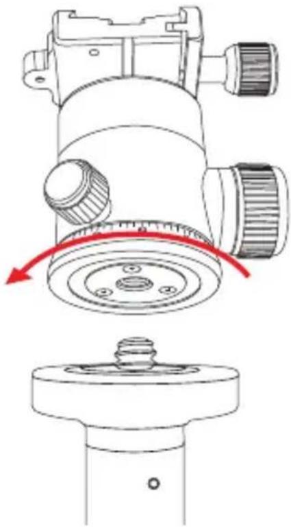
natural_image
Technical line drawing of a mechanical device with a red arrow indicating rotation or adjustment (no text or symbols present)MOUNTING THE BALLHEAD
When returning the ballhead to the tripod, follow these steps:
- Tighten all of the knobs on the head.
- Align the ballhead socket with the tripod mounting screw.
- Rotate the ballhead clockwise onto the tripod, and tighten it by hand. To prevent damage to the ballhead and mounting screw, do not overtighten.
Note: If a different size mounting screw is needed to mount the ballhead, refer to The Tripod Mounting Screw section above for instructions.
natural_image
Technical diagram of a device's internal structure with two arrows indicating assembly or connection points (no text or symbols present)MOUNTING THE QUICK-RELEASE PLATE TO THE CAMERA
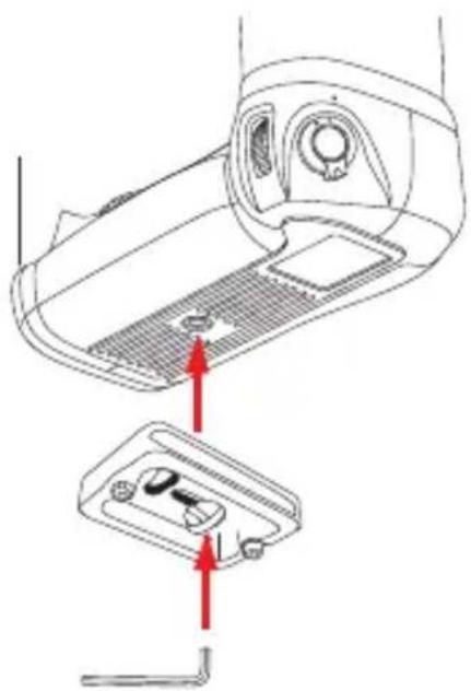
The quick-release plate has a 1/4-20 screw that fits most cameras.
-
Loosen the quick-release knob by turning it counterclockwise, and remove the quick-release plate from the ballhead.
-
Align the mounting screw with the threaded socket on the base of the camera.
-
Use the supplied hex key, a slotted screwdriver, or the D-ring to tighten the screw into the camera's socket.
Ballhead Operation (continued)
Note: If a 3/8-inch mounting screw is needed, use the included 1/4 to 3/8 adapter bushing.
Warning: Some manufacturers' plates do not meet our specifications and may not lock your equipment securely in the Oben quick-release clamp. Please test all camera and lens plates made by manufacturers other than Oben to ensure compatibility.
MOUNTING THE CAMERA AND QUICK-RELEASE PLATE TO THE BALLHEAD
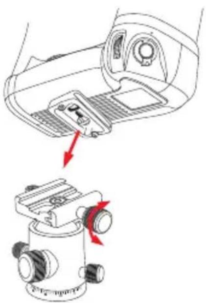
After mounting the quick-release plate to your camera, make sure that all knobs on the ballhead are tightened, except for the quick-release knob.
-
Turn the quick-release knob counterclockwise until it stops.
-
Mount the camera to the ballhead by placing one edge of the quick-release plate into the ballhead. Then lower the other side until the quick-release plate is lying flat in the quick-release clamp.
Note: Make sure the mounting screw's D-ring is flush with the bottom of the plate.
- Turn the quick-release knob clockwise to lock the plate.
natural_image
Diagram showing a car interior with a sensor device and a camera module, both without any text or symbols.Warning: Always use one hand to secure the camera while adjusting the ballhead, and make sure that the lock is engaged before letting go of the camera.
natural_image
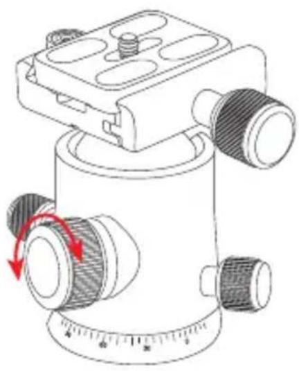
Technical line drawing of a mechanical device with no visible text or symbolsThe main locking knob locks and unlocks the ballhead, which allows for changing the position of the camera.
When changing camera positions via the main locking knob, always keep one hand on the camera.
Turn the knob counterclockwise to unlock the head, and clockwise to lock it. Make sure that the knob is firmly tightened before letting go of the camera.
Use the 90° groove to switch between landscape and portrait orientations.
Ballhead Operation (continued)
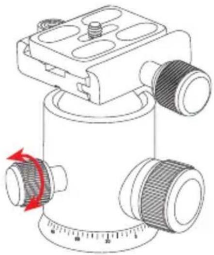
TENSION KNOB
(BZ-217T & BZ-226T BALLHEADS)
The tension knob is used to control the amount of friction on the ball in order to maintain strict control when positioning it. The tension knob is the medium-sized knob, and it has a different look and texture than the main and panning locking knobs so you won't confuse the two, even if you're operating them by touch.
natural_image
Technical line drawing of a mechanical device with a circular dial and directional arrow (no text or symbols)ADJUSTING THE FRICTION (BZ-217T & BZ-226T BALLHEADS)
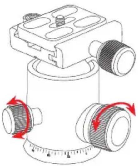
To adjust the friction accurately, follow these steps:
natural_image
Diagram of a mechanical device with rotating components and red arrows indicating motion (no text or symbols)-
Turn the locking knob and the tension knob clockwise until they are completely tightened. Then mount the camera and lens combination that you will regularly use.
-
Once the camera is securely mounted, hold the camera with one hand and completely loosen the locking knob by turning it counterclockwise until it stops. Then gradually loosen the tension knob until you reach the desired friction level.
-
Tighten the locking knob to secure the camera in place, or when you aren't holding onto the camera.
Ballhead Operation (continued)
PANORAMIC BASE
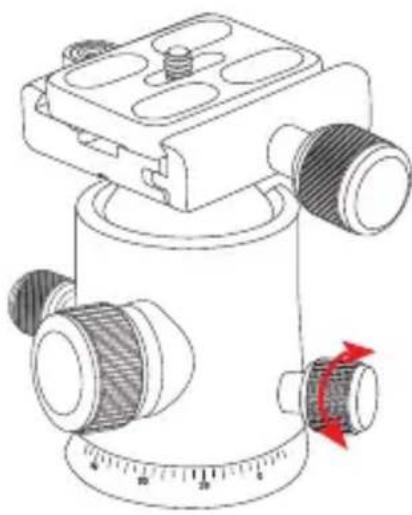
The base of the ballhead can be independently rotated 360°. The base is controlled by loosening the pan knob.
- Twist the knob counterclockwise to unlock the base.
- Rotate the base to the desired position, and then lock the base by turning the knob clockwise.
Note: Degree markings on the base of the ballhead can be used to accurately set up panoramic shots.
natural_image
Technical line drawing of a mechanical scale with adjustment knob (no text or symbols)Tripod Operation
LEG LENGTH ADJUSTMENT
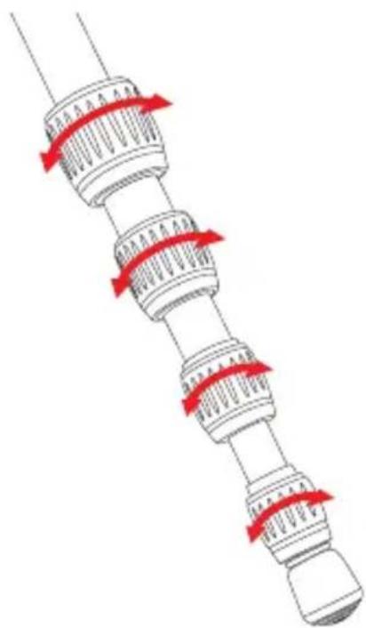
To independently adjust the height of each leg, do the following:
- Loosen the twist locks enough so that the legs can be adjusted.
Note: Don't over-loosen the twist locks.
-
Adjust the leg to the desired height.
-
Tighten the twist locks to secure the leg in place.
natural_image
Diagram of a mechanical component with red directional arrows indicating motion or force (no text or symbols)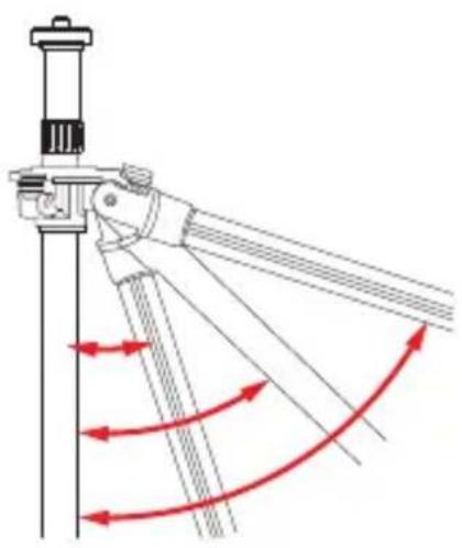
natural_image
Diagram of a mechanical linkage system with red curved arrows indicating motion or force direction (no text or symbols)LEG ANGLE ADJUSTMENT
For stable support when shooting on uneven terrain, each leg can be adjusted to a preset angle. To set the leg angle, do the following:
-
Press and hold the leg angle adjustment lock.
-
Set the angle of the leg to one of the three preset positions.
-
Release the lock to secure the leg at the desired angle.
CENTER-COLUMN ADJUSTMENT
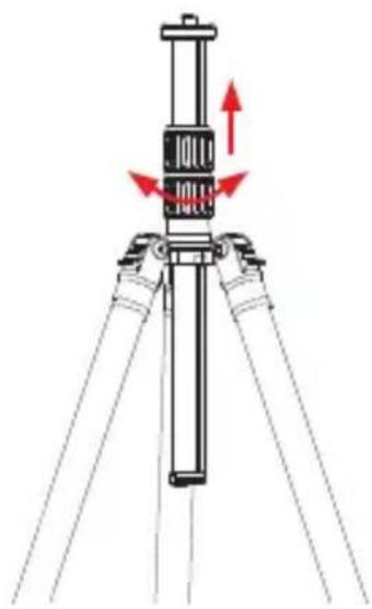
The center column can be used to adjust the height of the camera. Fully extending the center column after the legs have been completely extended will place the camera at the highest position possible with this tripod.
-
Turn the locking collar counterclockwise to unlock the center column.
-
Adjust the center column to the desired height.
-
Lock the column in place by turning the locking collar clockwise.
natural_image
Diagram of a tripod-mounted device with red directional arrows indicating movement or force (no text or symbols)Tripod Operation (continued)
AT/CT-3535
- If more height is needed, turn the center-column twist lock counterclockwise, and extend the upper center column to the desired height.
- Turn the twist lock clockwise to secure the column.
Note: Make sure the column is secure, but do not overtighten to avoid damaging the tripod.
LOW-ANGLE SETUP
The following instructions describe three ways to adjust the tripod for low-angle shots.
Using the Center Column
- Raise the center column to its maximum height. Then set the angle of the tripod legs to their lowest position.
- Loosen the locking collar and adjust the center column to its lowest height possible.
- Mount the camera on the ballhead.
Using the Low-Angle Center Column
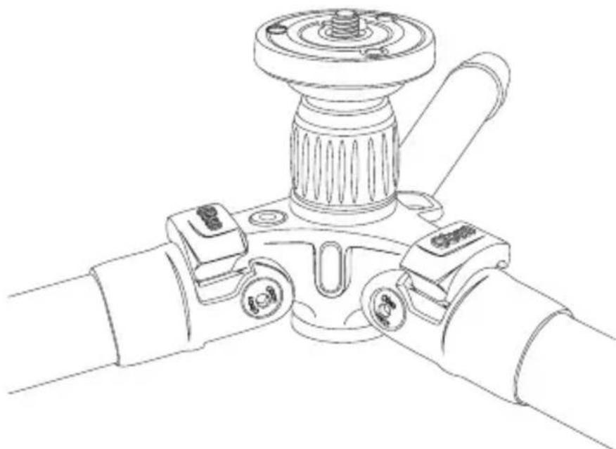
- Remove the ballhead from the tripod.
- Loosen the set screw, and unscrew the baseplate from the center column.
- Unscrew the weight hook from the bottom of the center column.
- Loosen the locking collar, and slide the center column off of the tripod.
- Insert the low-angle center column into the hole and tighten the locking collar. For extra stability, screw the weight hook into the bottom of the center column.
- Set the legs to their lowest position.
- Screw the baseplate onto the center column, and tighten the set screw.
- Screw the ballhead onto the baseplate.
natural_image
Line drawing of a mechanical device with two arms and a central hub (no text or symbols)Tripod Operation (continued)
Reversing the Center Column
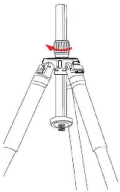
Reversing the center column allows for mounting the camera upside down in order to get close to the ground or surface. To reverse the center column, do the following:
- Unscrew the weight hook from the bottom of the center column.
- Loosen the locking collar and remove the center column from the tripod.
- Slide the center column into the tripod from underneath so that the ballhead is facing down toward the ground.
- Tighten the locking collar, and return the weight hook to the center column by screwing it in.
- Depending on the size of the camera, adjust the leg angle and height appropriately.
- Mount the camera to the quick-release plate, and attach the quick-release plate to the ballhead.
natural_image
Technical line drawing of a tripod-mounted tripod with a central column and a red arrow indicating rotation (no text or symbols)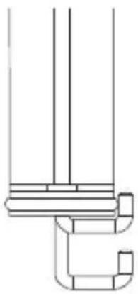
natural_image
Pure technical line drawing of a mechanical component without any text, numbers, or symbolsCOUNTERWEIGHT
When shooting in windy conditions or when using a telephoto lens, the stability of your camera is critical. A built-in spring-loaded hook at the bottom of the center column allows you to hang a counterweight, such as a sandbag (not included) or loaded equipment bag (not included), to provide increased stability.
Tripod Operation (continued)
SPIKED FEET
The rubber non-skid feet are for use indoors or on flat surfaces. Spikes are for soft ground, grass, sand, and uneven terrain.
To expose the spikes, follow these steps:
AT/CT-3535:
Remove the rubber feet by pulling them off. When finished using the spikes, replace the rubber feet.
AT/CT-3565 and AT/CT-3586:
Turn the retractable rubber feet clockwise.
When finished using the spikes, turn the rubber feet counterclockwise until they are extended all the way out and completely cover the spikes.
INTEGRATED MONOPOD
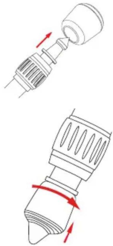
The leg with the extra rubber grip at the top of the shaft can be removed and used as a monopod. To assemble the monopod, follow these steps:
-
Unscrew the monopod leg from the tripod.
-
Unscrew the weight hook from the center column.
natural_image
Technical line drawing showing two mechanical components with red directional arrows indicating motion (no text or symbols)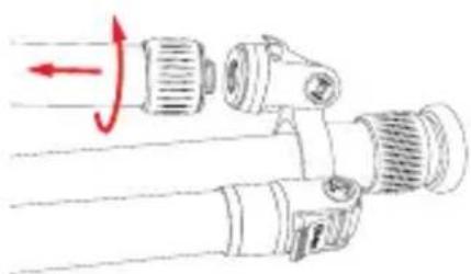
natural_image
Diagram of a mechanical device with rotating components and directional arrows (no text or symbols)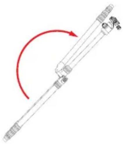
natural_image
Diagram of a mechanical device with a red curved arrow indicating rotation or motion (no text or symbols)-
Loosen the locking collar, and slide the center column out of the tripod.
-
Screw the end of the center column that housed the weight hook onto the end of the monopod leg.
Note: As an alternative to using the ballhead, the camera can be mounted directly to the baseplate. (See instructions on switching the mounting screw size in The Tripod Mounting Screw section on page 8.)
FOLDING LEGS
For the most compact storage and transport of your tripod, the legs can be folded up 180°.
-
Loosen the locking collar, adjust the center column to its maximum height, and tighten the locking collar until secure.
-
Push each leg slightly toward the center column, and press and hold the leg angle adjustment lock.
-
Fold the leg up above the center column.
-
The folded tripod and ballhead will fit neatly into the carry bag.
| AT/CT-3535 AT/CT-3565 AT/CT-3586 | ||||||
| Maximum Height with Center Column Extended | 51 in. (129 cm) | 61.8 in. (157 cm) | 62.5 in. (158.7 cm) | |||
| Maximum Height w/o Center Column Extended | 41 in. (104 cm) | 53.3 in. (135.4 cm) | 54 in. (137.1 cm) | |||
| Minimum Height 8 | 2 in. (21 cm) | 9.1 in. (23.2 cm) | 8.5 in. (21.5 cm) | |||
| Folded Length 12.3 | in. (31.3 cm) | 16.1 in. (40.9 cm) | 16.6 in. (42.3 cm) | |||
| Maximum Load 9 lb. (4.1 kg) | 20 lb. (9.1 kg) | 27 lb. (12.24 kg) | ||||
| Weight | 2.85 lb. (1.29 kg) | 2.5 lb. (1.13 kg) | 3.7 lb. (1.68 kg) | 3.2 lb. (1.45 kg) | 4.5 lb. (2 kg) | 4 lb. (1.82 kg) |
| Leg Sections 5 5 5 | ||||||
| Monopod Maximum Height | 52.5 in. (133.2 cm) | 64.1 in. (163 cm) | 65.2 in. (165.7 cm) | |||
| Spikes Yes Yes Yes | ||||||

Warnings:
- Do not exceed the tripod's maximum load capacity (see tag on tripod).
- Ensure that all appropriate locks are engaged when necessary.
- Tripod should be used only in temperatures between -22^ and 140^ Fahrenheit.
- Do not operate in salt water. Dry tripod off if it becomes wet.
- Remove the camera from the tripod during transport.
- Keep out of reach of children.
- To avoid injury, always support the top of the center column with one hand while adjusting height and locking the twist lock with the other hand.
OPTIONAL ACCESSORIES
Oben Tripod Strap with Quick-Release Loop and Spring Lock
TS-10
TS-100
Oben Deluxe Tripod Strap with Swivel Clip
TS-110
Oben Tripod Strap with Two Quick-Release Loops
TS-20
TS-200
Oben Tripod Hammock
- STB-10
Visit our website at ObenSupports.com
for more Oben products.
Oben is a registered trademark of the Gradus Group. © 2018 Gradus Group LLC. All Rights Reserved.