96BDF - Monitor Samtron - Free user manual and instructions
Find the device manual for free 96BDF Samtron in PDF.


User questions about 96BDF Samtron
0 question about this device. Answer the ones you know or ask your own.
Ask a new question about this device
Download the instructions for your Monitor in PDF format for free! Find your manual 96BDF - Samtron and take your electronic device back in hand. On this page are published all the documents necessary for the use of your device. 96BDF by Samtron.
USER MANUAL 96BDF Samtron
text_image
Index | Safety Instructions | Introduction | Setup | On-Screen Display | Troubleshooting | Specifications | Information PDF Document Adobe Acrobat Reader InstallationSAMTRON 96BDF/98BDF
text_image
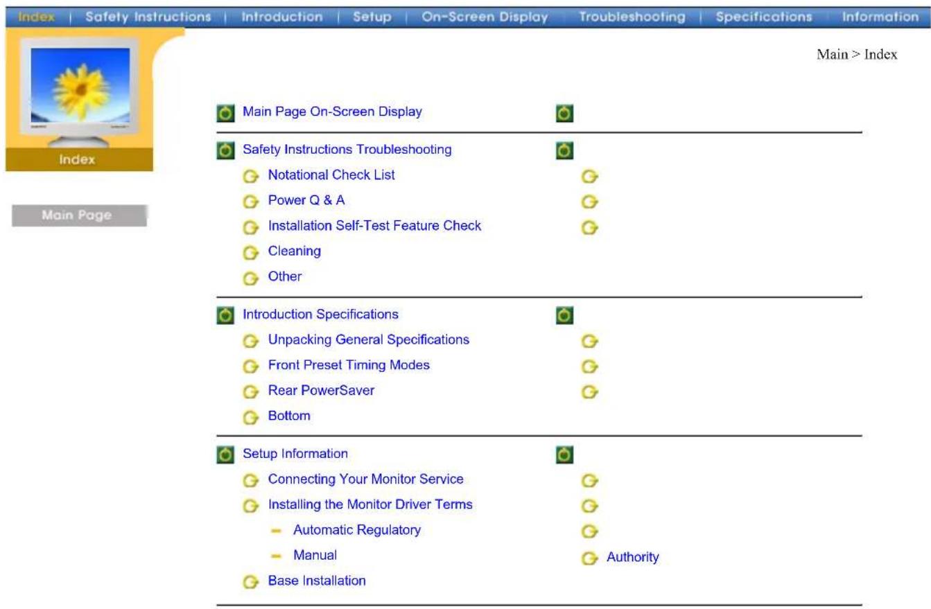
Index | Safety Instructions | Introduction | Setup | On-Screen Display | Troubleshooting | Specifications | Information Main > Index Index Main Page Main Page On-Screen Display Safety Instructions Troubleshooting Notational Check List Power Q & A Installation Self-Test Feature Check Cleaning Other Introduction Specifications Unpacking General Specifications Front Preset Timing Modes Rear PowerSaver Bottom Setup Information Connecting Your Monitor Service Installing the Monitor Driver Terms Automatic Regulatory Manual Base Installation Authority
text_image
Index | Safety Instructions | Introduction | Setup | On-Screen Display | Troubleshooting | Specifications | Information Main > Safety Instructions > Notational Safety Instructions Notational Power Installation Clean Other Main Page Please read the following safety instructions as they are designed to prevent damage to property and harm to the user. Warning / Caution Failure to follow directions noted by this symbol could result in bodily harm or damage to equipment.Notational Conventions

Prohibited Important to read and understand at all times

Do not disassemble Disconnect the plug from the outlet

Do not touch Grounding to prevent an electric shock
| Index | Safety Instructions | Introduction | Setup | On-Screen Display | Troubleshooting | Specifications | Information | ||
 Safety InstructionsNotationalPowerInstallationCleanOtherMain Page Safety InstructionsNotationalPowerInstallationCleanOtherMain Page |  | When not used for extended periods of time, set your PC to DPMS. If using a screen saver, set it to the active screen mode.If the size of your monitor is small, or if the same image is present for long periods of time, you may see afterimages due to damage to the fluorescent substance on the inside of the CRT. |
 | Do not use a damaged or loose plug.This may cause an electric shock or fire. | |
 | Do not pull the plug out by the wire nor touch the plug with wet hands.This may cause an electric shock or fire. | |
 | Use only a properly grounded plug and recepticle.An improper ground may cause electric shock or equipment damage. | |
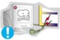 | Do not excessively bend the plug and wire nor place heavy objects upon them, which could cause damage.Failure to do so may cause an electric shock or fire. | |
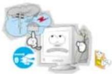 | Disconnect the plug from the outlet during storms or lightening or if it is not used for a long period of time.Failure to do so may cause an electric shock or fire. | |
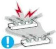 | Do not connect too many extension cords or plugs to an outlet.This may cause a fire. | |
| Safety Instructions ► Notational ► Power ► Installation ► Clean ► Other Main Page | Main > Safety Instructions > Installation | |
| Do not cover the vents on the monitor cabinet. · Bad ventilation may cause a breakdown or fire. | ||
| Put your monitor in a location with low humidity and a minimum of dust. · An electric shock or fire could result inside the monitor. | ||
| Do not drop the monitor when moving it. · This may cause damage to the product or human body. | ||
| Place the monitor on a flat and stable surface. · The monitor can cause injury by falling. | ||
| Set down the monitor carefully. · It could be damaged or broken. | ||
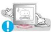
| Do not place the monitor face down. · The CRT surface may be damaged. | ||
| Do not use the monitor without the monitor stand. · It could break down or cause a fire due to bad ventilation. · If the monitor must be used without the supplied stand, take steps to insure proper ventilation. | ||
Notational
Power
Installation
Clean
Other


Main > Safety Instructions > Installation
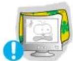
Do not cover the vents on the monitor cabinet.
• Bad ventilation may cause a breakdown or fire.
Put your monitor in a location with low humidity and a minimum of dust.
- An electric shock or fire could result inside the monitor.
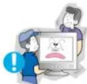
Do not drop the monitor when moving it.
• This may cause damage to the product or human body.
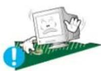
Place the monitor on a flat and stable surface.
• The monitor can cause injury by falling.
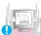
Set down the monitor carefully.
- It could be damaged or broken.
Do not place the monitor face down.
• The CRT surface may be damaged.
Do not use the monitor without the monitor stand.
- It could break down or cause a fire due to bad ventilation.
- If the monitor must be used without the supplied stand, take steps to insure proper ventilation.
| Index | Safety Instructions | Introduction | Setup | On-Screen Display | Troubleshooting | Specifications | Information |
 | Main > Safety Instructions > Clean | ||||||
| Safety Instructions | When cleaning the monitor case or the surface of the CRT, wipe with a slightly moistened, soft fabric.Do not clean Flat monitor with water. Use a water-diluted mild detergent. | ||||||
| NotationalPowerInstallationCleanOther |  | (Some detergents contain significant amounts of alcohol-based solvents, which can damage (color change) or crack the monitor case. The antiglare/anti-static surface coating on the CRT may also be affected.)Dilute the detergent (1:10 ratio) with water before using. | |||||
Main Page
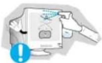


Do not spray detergent directly on the monitor.
Use the recommended detergent with a smooth cloth.
- You can prevent the coated CRT from being damaged or the monitor cabinet from being dissolved, cracked or discolored.
- You can buy a recommended detergent at any Samsung Service Center.

Caution: Use a recommended detergent only, as other surfactants containing large amounts of alcohol, solvent or other strong substances, can discolor or crack the monitor or damage the coated CDT.

If the connector between the plug and the pin is dusty or dirty, clean it properly with a dry cloth.
- A dirty connector can cause an electric shock or fire.

Do not set a glass of water, chemicals or any small metal objects on the monitor.
• This may cause damage, electric shock or a fire.
- If a foreign substance gets into the monitor, disconnect the plug and then contact a service center.
| Index | Safety Instructions | Introduction | Setup | On-Screen Display | Troubleshooting | Specifications | Information | |
| Safety Instructions ► Notational ► Power ► Installation ► Clean ► Other Main Page | Main > Safety Instructions > Other |
| Do not remove cover(or back). No user serviceable parts inside. · This may cause an electric shock or a fire. · Refer servicing to qualified service personnel. | |
| If your monitor does not operate normally - in particular, if there are any unusual sounds or smells coming from it - unplug it immediately and contact an authorized dealer or service. · This may cause an electric shock or a fire. | |
| Do not place any heavy objects on the monitor. · This may cause an electric shock or a fire. | |
| For each hour of looking at the monitor, you should let your eyes rest for 5 minutes. · This will reduce eye fatigue. | |
| Do not use or store inflammable substances near the monitor. · This may cause an explosion or fire. | |
| Do not try to move the monitor by pulling on the wire or the signal cable. · This may cause a breakdown, electric shock or a fire due to damage to the cable. | |
| Do not move the monitor right or left by pulling only the wire or the signal cable. · This may cause a breakdown, electric shock or a fire due to damage to the cable. | |
| Never insert anything metallic into the monitor openings. · This may cause an electric shock, fire or injury. | |

Keep the monitor away from any magnetic substances.
- This may cause discoloring or distortion of the image.
text_image
Index | Safety Instructions | Introduction | Setup | On-Screen Display | Troubleshooting | Specifications | Information Introduction ► Unpacking ► Front ► Rear ► Bottom Main Page ● Monitor and Stand ● Power Cord Stand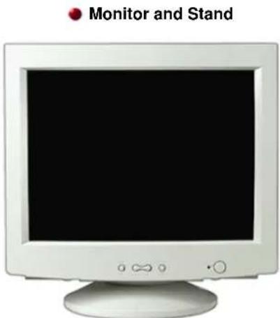
text_image
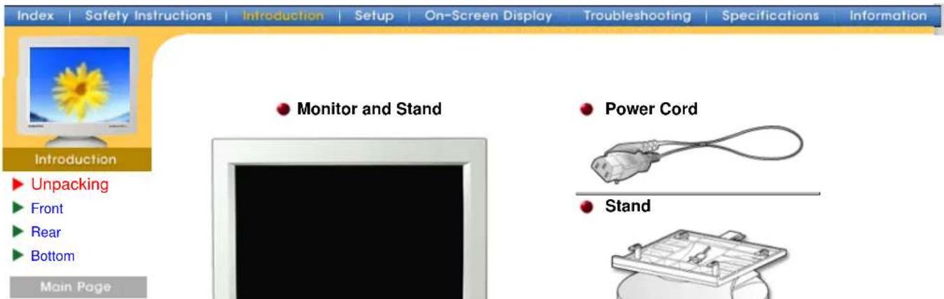
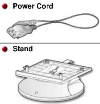
Monitor and Stand(Some models include a stand attached.) Please make sure the following items are included with your monitor. If any items are missing, contact your dealer.
text_image
Power Cord Stand
text_image
Quick Setup Guide
text_image
Warranty Card (Not available in all locations) User's Guide and Driver Installation CD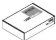
text_image
Index | Safety Instructions | Introduction | Setup | On-Screen Display | Troubleshooting | Specifications | Information Introduction ► Unpacking ► Front ► Rear ► Bottom Main Page Exit Menu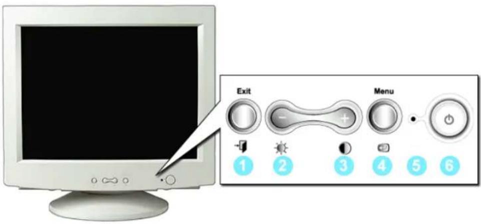
text_image
Exit Menu 1 2 3 4 5 6- Exit button Use this button to Exit the active menu or the OSD.
2.3. Adjust buttons These buttons allow you to highlight and adjust items in the menu. - Menu button Use this button to open the OSD and activate a highlighted menu item.
- Power indicator This light glows green during normal operation, and blinks green once as the monitor saves your adjustments.
- Power button Use this button to turn the monitor on and off.
Note: See PowerSaver described in the manual for further information regarding power saving functions. For energy conservation, turn your monitor OFF when it is not needed, or when leaving it unattended for long periods.
text_image
Index | Safety Instructions | Introduction | Setup | On-Screen Display | Troubleshooting | Specifications | Information Introduction ► Unpacking ► Front ► Rear ► Bottom Main Page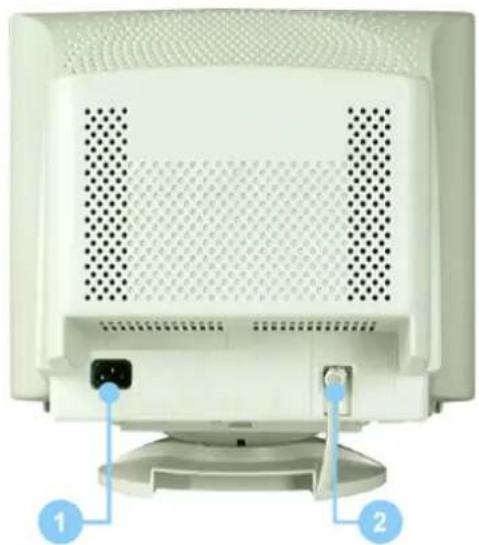
natural_image
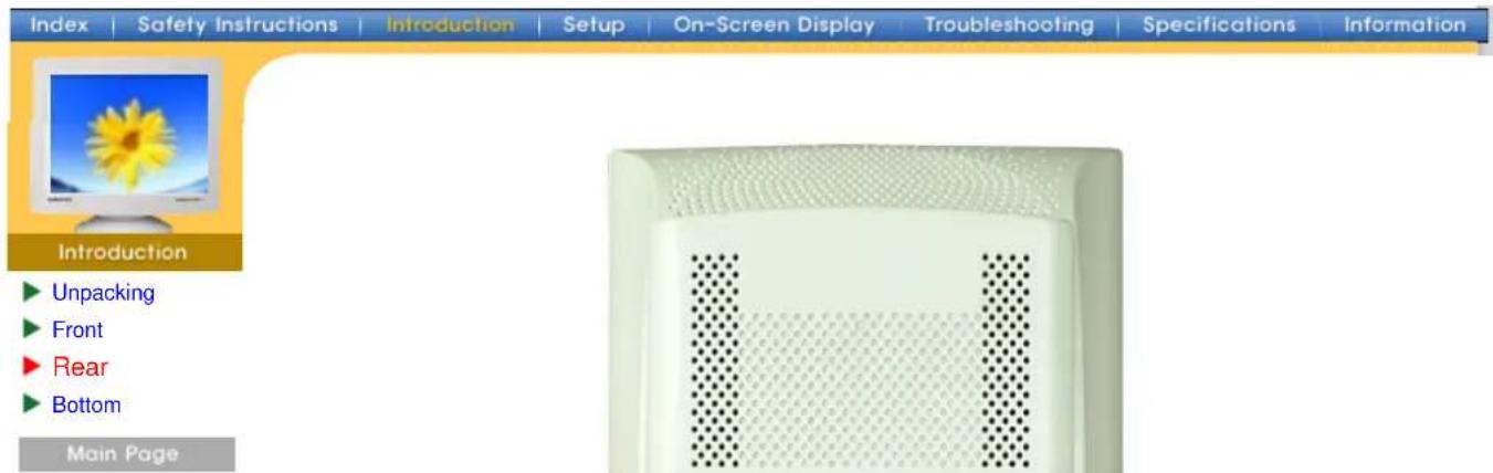
Front view of a white computer monitor with ventilation grilles and a base mount (no text or symbols visible)(The configuration at the back of the monitor may vary from product to product.)
- Power port Connect the power cord for your monitor to the power port on the back of the monitor.
- Signal Cable Connect the signal cable to the video port on your computer, video board, video card, or graphics card.
Note: See Connecting Your Monitor for further information regarding cable connections.
text_image
Index | Safety Instructions | Introduction | Setup | On-Screen Display | Troubleshooting | Specifications | Information Introduction ► Unpacking ► Front ► Rear ► Bottom Main Page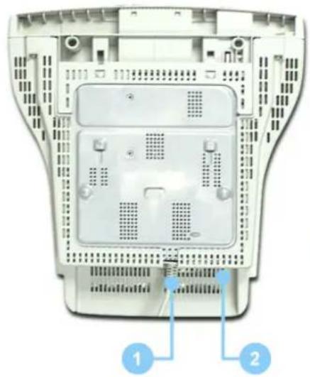
natural_image
Internal view of a computer chassis showing internal components and ventilation slots (no text or symbols visible)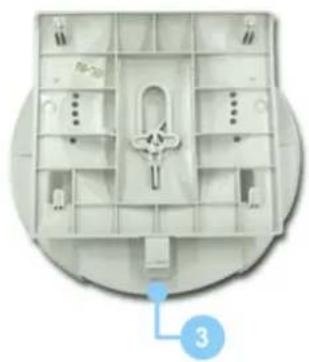
natural_image
Interior view of a mechanical housing or enclosure with internal compartments and mounting holes (no visible text or symbols)- Signal Cable Connect the signal cable to the video port on your computer, video board, video card, or graphics card.
- Power port Connect the power cord for your monitor to the power port on the back of the monitor.
- Tilt/Swivel Base You can separate the base from the monitor.
text_image
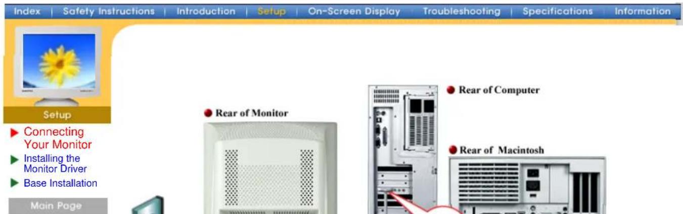
Index | Safety Instructions | Introduction | Setup | On-Screen Display | Troubleshooting | Specifications | Information Setup ► Connecting Your Monitor ► Installing the Monitor Driver ► Base Installation Main Page Rear of Monitor Rear of Computer Rear of Macintosh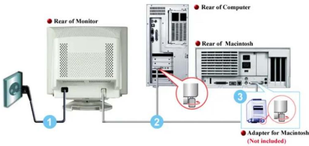
text_image
Rear of Monitor 1 2 Rear of Computer Rear of Macintosh 3 Adapter for Macintosh (Not included)- Connect the power cord for your monitor to the power port on the back of the monitor. Plug the power cord for the monitor into a nearby outlet.
- Connect the signal cable to the video port on your computer, video board, video card, or graphics card.
- If you are using a Macintosh computer, connect the cable to a Macintosh adapter, and set the pins on your adapter(Adapter not included). A PC-compatible computer does not need an adapter.
- Turn on your computer and monitor. If your monitor displays an image, installation is complete.

text_image
Index | Safety Instructions | Introduction | Setup | On-Screen Display | Troubleshooting | Specifications | Information Automatic ManualConnecting Your Monitor
Installing the Monitor Driver
Base Installation
Main Page

When prompted by the operating system for the monitor driver, insert the CD-ROM included with this monitor. Driver installation is slightly different from one operating system to another. Follow the directions as appropriate for the operating system you have.
Prepare a blank disk and download the driver program file at the Internet web site shown here.
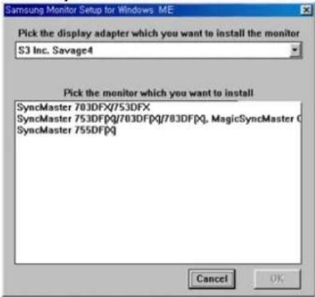
- Insert CD into the CD-ROM driver.
- Click "Windows ME Driver".
- Choose your monitor model in the model list, then click the "OK" button.
text_image
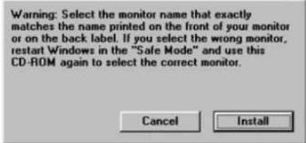
Samsung Monitor Setup for Windows ME Pick the display adapter which you want to install the monitor S3 Inc. Savage4 Pick the monitor which you want to install SyncMaster 703DFX/753DFX SyncMaster 753DFX/703DFX/783DFX, MagicSyncMaster C SyncMaster 755DFX Cancel OK- Click the "Install" button in the "Warning" window.
text_image
Warning: Select the monitor name that exactly matches the name printed on the front of your monitor or on the back label. If you select the wrong monitor, restart Windows in the "Safe Mode" and use this CD-ROM again to select the correct monitor.- Monitor driver installation is completed.
Windows XP/2000
- Insert CD into the CD-ROM driver.
- Click "Windows XP/2000 Driver".
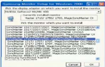
- Choose your monitor model in the model list, then click the "OK" button.
text_image
Samsung Monitor Setup for Windows 2000 Pick the display adapter on which you want to install the monitor NVIDIA GeForce2 MX/MK 400 Currently installed monitor Master 1715/1755/1705, MagicSyncMaster Ox Pick the monitor which you want to install SyncMaster 1517/1557/1507, MagicSyncMaster CX1518D(An SyncMaster 1517/1557/1507, MagicSyncMaster CX1518D(Dit SyncMaster 1519B/1559M, MagicSyncMaster CX156A SyncMaster 1519B/1559M/1708M/1708M), MagicSyncMaster CX SyncMaster 1719P/175MP, MagicSyncMaster IB1700MP SyncMaster 1719P/175MP, MagicSyncMaster CX176A SyncMaster 171T/175T/170T, MagicSyncMaster CX176D( SyncMaster 171T/175T/170T, MagicSyncMaster CX176D( SyncMaster 1719B/175MP, MagicSyncMaster CX176A SyncMaster 1818/1858/1808, MagicSyncMaster CX1858(M) SyncMaster 1818/1858/1808, MagicSyncMaster CX1858(An) SyncMaster 181T/185T/180T, MagicSyncMaster CX195D(Dig SyncMaster 450B(T) / <450N3b Samsung SyncMaster 5107FT Cancel OK- Click the "Install" button in the "Warning" window.
text_image
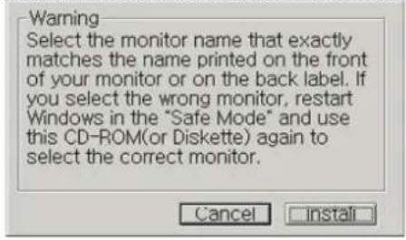
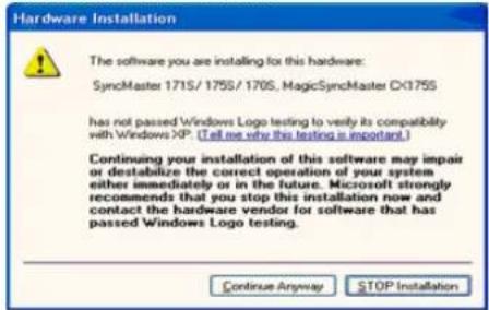
Warning Select the monitor name that exactly matches the name printed on the front of your monitor or on the back label. If you select the wrong monitor, restart Windows in the "Safe Mode" and use this CD-ROM(or Diskette) again to select the correct monitor. Cancel Install- If you can see following "Message" window, then click the "Continue Anyway" button. Then click "OK" button.
text_image
Hardware Installation The software you are installing for this hardware: SyncMaster 1715/1755/170S, MagicSyncMaster CX175S has not passed Windows Logo testing to verify its compatibility with Windows XP. (Tell me why this testing is important.) Continuing your installation of this software may impair or destabilize the correct operation of your system either immediately or in the future. Microsoft strongly recommends that you stop this installation now and contact the hardware vendor for software that has passed Windows Logo testing. Continue Anyway STOP InstallationThis monitor driver has been applied to Microsoft for the Windows logo, and this installation does not damage the correct operation of your system. The Windows logo certified driver will be posted on Samtron Monitor Homepage in the future then you can download it.
http://www.samtron.com/.
- Monitor driver installation is completed.
text_image
Index | Safety Instructions | Introduction | Setup | On-Screen Display | Troubleshooting | Specifications | Information Setup Automatic Manual Windows XP | Windows 2000 | Windows Me | Windows NT | Linux Connecting Your Monitor Installing the Monitor Driver Base Installation Main Page Note When prompted by the operating system for the monitor driver, insert the CD-ROM included with this monitor. Driver installation is slightly different from one operating system to another. Follow the directions as appropriate for the operating system you have.When prompted by the operating system for the monitor driver, insert the CD-ROM included with this monitor. Driver installation is slightly different from one operating system to another. Follow the directions as appropriate for the operating system you have.
Prepare a blank disk and download the driver program file at the Internet web site shown here.
- Insert CD into the CD-ROM driver.
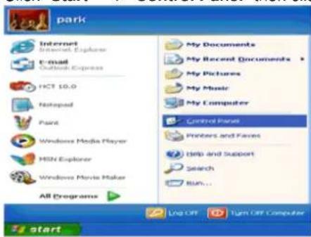
- Click "Start" → "Control Panel" then click the "Appearance and Themes" Icon.
text_image
park Internet Microsoft Explorer E-mail Outlook Express FCT 10.0 Notepad Paint Windows Media Player MSN Explorer Windows Movie Maker All Programs My Documents My Recent Documents My Pictures My Music My Computer Control Panel Printers and Favers Help and Support Search Run... Log Off Turn Off Computer start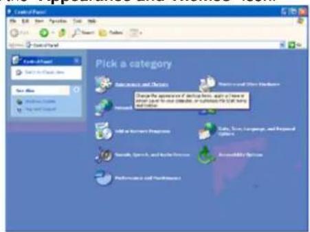
text_image
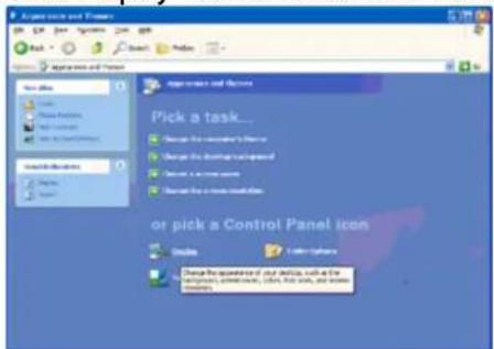
Control Panel File Edit View Insert Tools Help Start Menu End Sub-Panel Select All-View Select to Close Now Save As Windows Options Help My Support Pick a category Set up access and access Change the appearance of device here, again a new or similar device for our OSOS, or to ensure PC & AT&T help and access. Find an all-View Interface Add to Start Properties Make, Save, Learn, Language, and Readout Properties Send, Send, Apply, and Update Services Accessibility Options Performance and Performance1- Click "Display" icon and choose the "Settings" tab then click "Advanced..".
text_image
Pick a task... Design the controller's menu Design the dashboard environment Design the user session Design the user session or pick a Control Panel icon Check Finish Options Change frequency of my info, with the user session, configuration, color, size, and time. Details.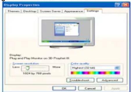
text_image
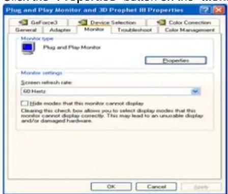
Display Properties Themes Desktop Screen Server Appearance Settings Display Plug and Play Mouse on 3D Prophet III Screen resolution More Low 1024 by 769 pixels Color quality Highest (32 dB) Trouble about Advanced OK Cancel Apply- Click the "Properties" button on the "Monitor" tab and select "Driver" tab.
text_image
Plug and Play Monitor and 3D Prophet III Properties GeForce3 Device Selection Color Connection General Adapter Monitor Troubleshoot Color Management Monitor type Plug and Play Monitor Properties Monitor settings Screen refresh rate 60 Hz Hide modes that this monitor cannot display Cleaning this check box allows you to select display modes that this monitor cannot display correctly. This may lead to an unusable display and/or damaged hardware. OK Cancel Apply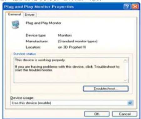
text_image
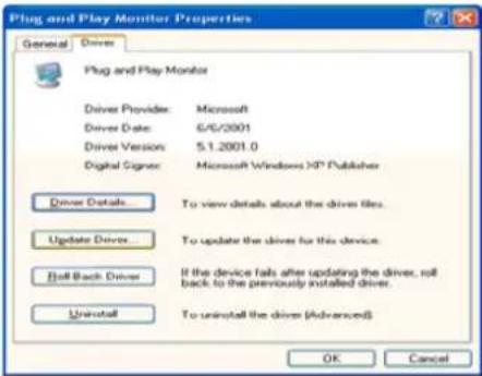
Plug and Play Monitor Properties General Driver Plug and Play Monitor Device type: Monitors Manufacturer: (Standard monitor types) Location:,on 3D Prophet III Device status This device is working proper. If you are having problems with this device, click Troubleshoot to start the troubleshooter. Troubleshoot... Device usage: Use this device (enable) OK Cancel- Click "U p date Driver.." and select "Install from a list or.." then click "Next" button.
text_image
Plug and Play Monitor Properties General Driver Plug and Play Monitor Driver Provider: Microsoft Driver Date: 6/6/2001 Driver Version: 5.1.2001.0 Digital Signor: Microsoft Windows XP Publisher Driver Details To view details about the drive files. Update Driver To update the driver for this device. Roll Back Driver If the device fails after updating the driver, roll back to the previously installed driver. Uninstall To uninstall the driver (Advanced) OK Cancel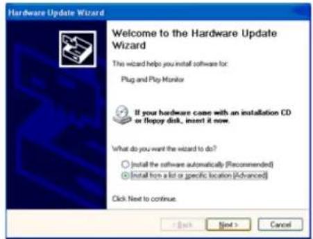
text_image
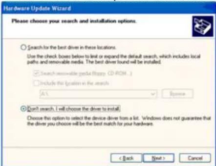
Hardware Update Wizard Welcome to the Hardware Update Wizard This wizard helps you install software for: Plug and Play Monitor If your hardware came with an installation CD or floppy disk, insert it now. What do you want the wizard to do? ○ Install the software automatically (Recommended) ● Install from a list or specific location (Advanced) Click Next to continue.- Select "Don't search, I will..." then click "Next" and then click "Have disk".
text_image
Hardware Update Wizard Please choose your search and installation options. Search for the best driver in these locations. Use the check boxes below to limit or expand the default search, which includes local paths and removable media. The best driver found will be installed. Search reasonable media (Happy CD-ROM...) Include this location in the search A: Browse Don't search. I will choose the driver to install. Choose this option to select the device driver from a lot. Windows does not guarantee that the driver you choose will be the best match for your hardware. < Back Next > Cancel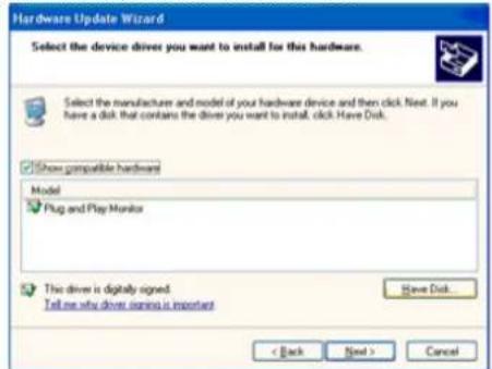
text_image
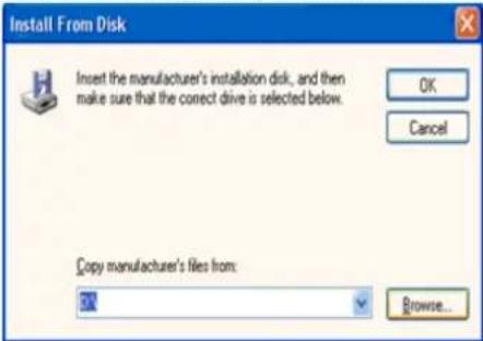
Hardware Update Wizard Select the device drives you want to install for this hardware. Select the manufacturer and model of your hardware device and then click Next. If you have a disk that contains the drivers you want to install, click Have Disk. Show compatible hardware Model Plug and Play Monitor This driver is digitally signed. Tell me why driver signing is important Have Disk... < Back Next > Cancel- Click the "Browse" button then choose A:(D:\Driver) and choose your monitor model in the model list and click the "Next" button.
text_image
Install From Disk Insert the manufacturer's installation disk, and then make sure that the correct drive is selected below. OK Cancel Copy manufacturer's files from: Browse...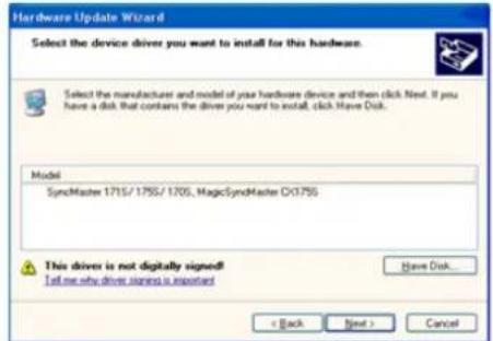
text_image
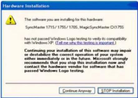
Hardware Update Wizard Select the device driver you want to install for this hardware. Select the manufacturer and model of your hardware device and then click Next. If you have a disk that contains the driver you want to install, click Have Disk. Model: SyncMaster 1715/1755/1705, MagicSyncMaster CX3755 This driver is not digitally signed! I tell me why driver stories is important Have Disk... < Back Next > Cancel- If you can see following "Message" window, then click the "Continue Anyway" button. Then click "OK" button.
text_image
Hardware Installation The software you are installing for this hardware: SyncMaster 1715/1755/1705, MagicSyncMaster CX175S has not passed Windows Logo testing to verify its compatibility with Windows XP. (Tell me why this testing is important.) Continuing your installation of this software may impair or destabilize the correct operation of your system either immediately or in the future. Microsoft strongly recommends that you stop this installation now and contact the hardware vendor for software that has passed Windows Logo testing. Continue Anyway STOP InstallationThis monitor driver has been applied to Microsoft for the Windows logo, and this installation does not damage the correct operation of your system. The Windows logo certified driver will be posted on Samtron Monitor Homepage in the future then you can download it. http://www.samtron.com/.
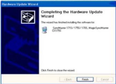
- Click the "Close" button then click "OK" button continually.
text_image
Hardware Update Wizard Completing the Hardware Update Wizard The wizard has finished installing the software for: SynchMaster 1715/1755/1705, MagicSynchMaster D:\1756 Click Finish to close the wizard. < Back Finish Cancel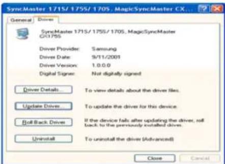
text_image
SyncMaster 1715/1755/1705, MagicSyncMaster CX... General Drivers SyncMaster 1715/1755/1705, MagicSyncMaster CX1755 Driver Provider: Samsung Driver Date: 9/11/2001 Driver Version: 1.0.0.0 Digital Signor: Not digitally signed Driver Details: To view details about the driver files. Update Driver: To update the driver for this device Ball Back Driver: If the device falls after updating the driver, will back to the previously installed driver. Uninstall: To uninstall the driver (Advanced) Close Cancel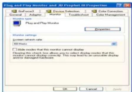
text_image
Plug and Play Monitor and 3D Prophet III Properties General Adapters Monitor Troubleshoot Color Connection Monitor type Play and Play Monitor Properties Monitor settings Screen refresh rate 60 Hz/Hz Hide modes that this monitor cannot display Clearing this check box allows you to select display modes that this monitor cannot display correctly. This may lead to an unusable display and/or damaged hardware OK Cancel Help- Monitor driver installation is completed.

Microsoft® Windows® 2000 Operating System

When you can see "Digital Signature Not Found" on your monitor, follow these steps.
- Choose "OK" button on the "Insert disk" window.
- Click the "Browse" button on the "File Needed" window.
- Choose A:(D:\Driver) then click the "Open" button and then click "OK" button.

How to install
- Click "Start", "Setting", "Control Panel".
- Double click the "Display" Icon.
- Choose the "Settings" tab and then click "Advanced..".
- Choose "Monitor".
Case1: If the "Properties" button is inactive, it means your monitor is properly configured. Please stop installation
Case2: If the "Properties" button is active, click the "Properties" button then follow next steps continually. - Click "Driver" and then click on "Update Driver.." then click on the "Next" button.
- Choose "Display a list of the known drivers for this device so that I can choose a specific driver" then click "Next" and then click "Have disk".
- Click the "Browse" button then choose A:(D:\Driver).
- Click the "Open" button, then click "OK" button.
- Choose your monitor model and click the "Next" button then click "Next" button.
- Click the "Finish" button then the "Close" button.
If you can see the "Digital Signature Not Found" window then click the "Yes" button. And click the "Finish" button then the "Close" button.

Microsoft® Windows® Millennium Operating System
- Click "Start", "Setting", "Control Panel".
- Double click "Display" icon.
- Select the "Settings" tab and click "Advanced Properties" button.
- Select the "Monitor" tab.
- Click the "Change" button in the "Monitor Type" area.
- Choose "Specify the location of the driver".
- Choose "Display a list of all the driver in a specific location.." then click "Next" button.
- Click the "Have Disk" button
- Specify A: D: then click "OK" button.
- Select "Show all devices" and choose the monitor that corresponds to the one you connected to your computer and click "OK".
- Continue choosing "Close" button and "OK" button until you close the Display Properties dialogue box. (You can get some other screen for warning message or others, then click the appreciate option for your monitor.)
Microsoft® Windows® NT Operating System
- Click Start, Settings, Control Panel, and then double-click Display icon.
- In Display Registration Information window, click Settings Tab and then click All Display Modes.
- Select a mode that you wish to use (Resolution, Number of colors and Vertical frequency) and then click OK.
- Click Apply button if you see the screen working normally after clicking Test. If the screen is not normal, change to a different mode (lower mode of resolution, colors or frequency).
Note: If there is no Mode at All Display Modes, select the level of resolution and vertical frequency by referring to the Preset Display Modes in the user guide.
Linux Operating System
To execute X-Window, you need to make the X86Config file, which is a type of system setting file.
- Press Enter at the first and the second screen after executing the X86Config file.
- The third screen is for setting your mouse.
- Set a mouse for your computer.
- The next screen is for selecting a keyboard.
- Set a Keyboard for your computer.
- The next screen is for setting your monitor.
- First of all, set a horizontal frequency for your monitor. (You can enter the frequency directly.)
- Set a vertical frequency for your monitor. (You can enter the frequency directly.)
- Enter the model name of your monitor. This information will not affect the actual execution of X-Window.
- You have finished setting up your monitor. Execute X-Window after setting other requested hardware.
text_image
Index | Safety Instructions | Introduction | Setup | On-Screen Display | Troubleshooting | Specifications | Information Setup ► Connecting Your Monitor ► Installing the Monitor Driver ► Base Installation Main Page Tilt/Swivel Base | Attaching and Removing the Base Tilt/Swivel Base With the built-in pedestal, you can tilt and/or swivel the monitor for the most comfortable viewing angle.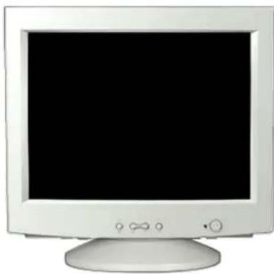
natural_image
Front view of a white CRT computer monitor with a black screen and control buttons (no visible text or symbols)Note: The base is detachable.
Attaching and Removing the Base
If your monitor was supplied with the base detached, attach the base as follows.
natural_image
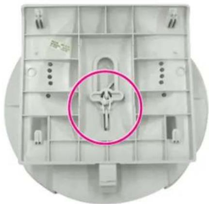
Top-down view of a white plastic enclosure with internal compartments and a pink circle highlighting a central feature (no text or symbols)Remove the twist-tie before attaching the base to the monitor.
natural_image
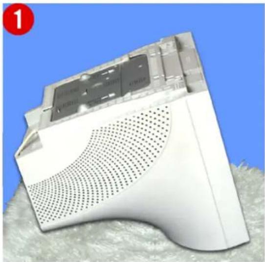
White electronic device with perforated base and gray panel, placed on textured surface against blue background (no visible text or symbols)Attaching the Base
- Place the monitor upside-down on a flat work surface.
- Align the tabs on the base with the corresponding slots on the bottom of the monitor.
- Press the base onto the monitor until the tabs are fully engaged in the slots.
- Push the base toward the front of the monitor until the release latch clicks into the locked position.
* Do not bend the snap.
Removing the Base
- Squeeze and pull up on the release latch on the base.
- Push the base toward the back of the monitor and lift up to remove the base.
Note: The base will align with the monitor slots in only one position.
On Screen Display (OSD) Menu System
text_image
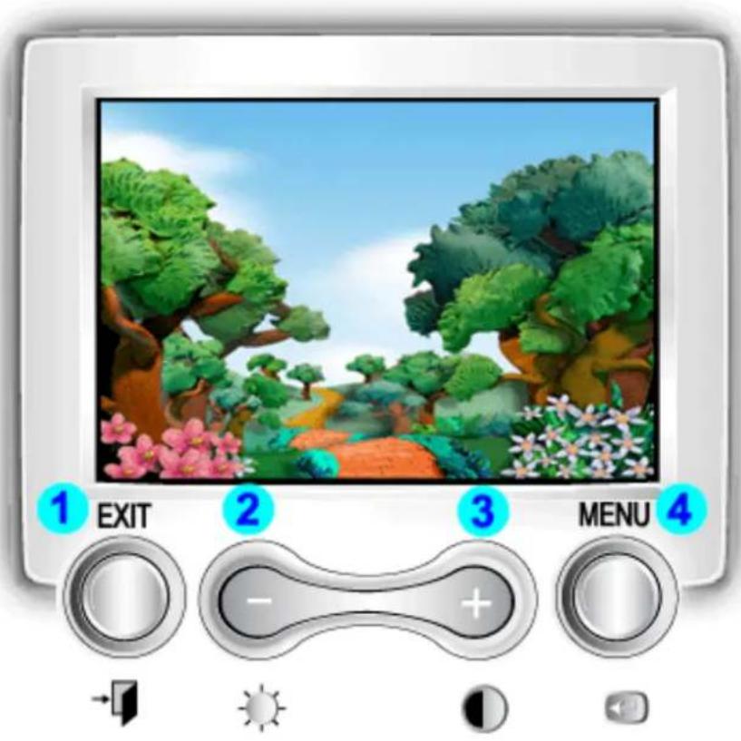
1 EXIT 2 3 MENU 41 Exit button: Use this button to Exit the active menu or the OSD.
2,3 Adjust buttons: These buttons allow you to highlight and adjust items in the menu.
4 Menu button: Use this button to open the OSD and activate a highlighted menu item.
On Screen Display (OSD) Menu System
Menu How to adjust
text_image
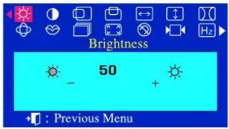
Brightness 50 + : Previous Menu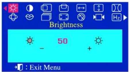
text_image
Brightness 50 - + +: Exit MenuBrightness
Adjust the Brightness.
1 With the menu off, push the menu ← button.
2 Push the - button or + button until the Brightness screen is displayed.
3 Push the menu ← button to open the Brightness adjustment screen.
4 Use the + button to increase the brightness or - button to decrease the brightness.
text_image
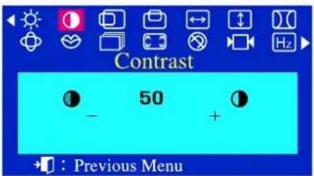
Contrast 50 + : Previous Menu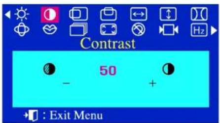
text_image
Contrast 50 - + : Exit MenuContrast
Adjust the Contrast.
1 With the menu off, push the menu ← button.
2 Push the - button or + button until the Contrast screen is displayed.
3 Push the menu ← button to open the Contrast adjustment screen.
4 Use the + button to increase the contrast or - button to decrease the contrast.
On Screen Display (OSD) Menu System
Menu How to adjust
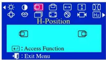
text_image
H-Position Access Function Exit Menu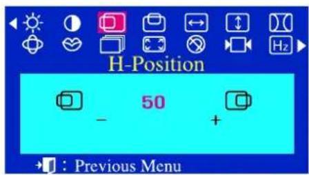
text_image
H-Position 50 - + : Previous MenuH-Position
Follow these instructions to change the Position of the monitor's entire display.
1 With the menu off, push the menu← button.
2 Push the - button or + button until the H-Position screen is displayed.
3 Push the menu ← button to open the H-Position adjustment screen.
4 Use the - and + buttons to change the Horizontal position of the monitor's viewing area.
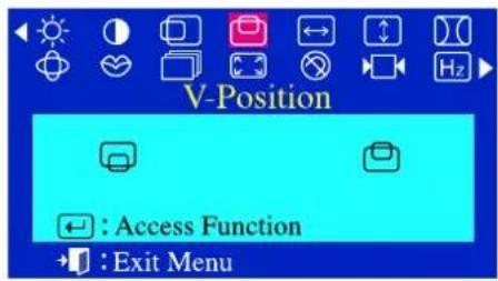
text_image
V-Position Access Function Exit Menu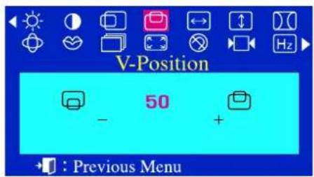
text_image
V-Position 50 - + : Previous MenuV-Position
Follow these instructions to change the Position of the monitor's entire display.
1 With the menu off, push the menu ← button.
2 Push the - button or + button until the V-Position screen is displayed.
3 Push the menu ← button to open the V-Position adjustment screen.
4 Use the - and + buttons to change the vertical position of the monitor's viewing area.
On Screen Display (OSD) Menu System
Menu How to adjust

text_image
H-Size Access Function Exit Menu H-Size 50 + Previous MenuH-Size
Follow these instructions to change the Size of the monitor's entire display.
1 With the menu off, push the menu ← button.
2 Push the - button or + button until the H-Size screen is displayed.
3 Push the menu ← button to open the H-Size adjustment screen.
4 Use the - and + buttons to change the Horizontal Size of the monitor's viewing area.
text_image
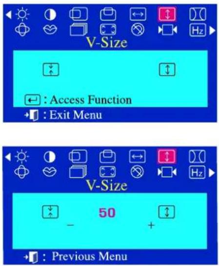
V-Size Access Function Exit Menu V-Size 50 + Previous MenuV-Size
Follow these instructions to change the Size of the monitor's entire display.
1 With the menu off, push the menu ← button.
2 Push the - button or + button until the V-Size screen is displayed.
3 Push the menu ← button to open the V-Size adjustment screen.
4 Use the - and + buttons to change the Vertical Size of the monitor's viewing area
On Screen Display (OSD) Menu System
Menu How to adjust
text_image
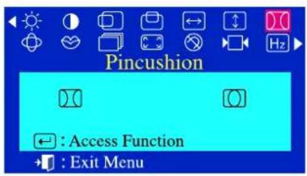
Pincushion Access Function Exit Menu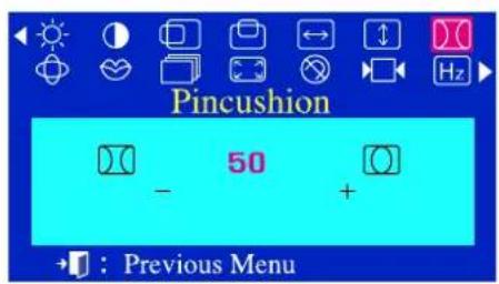
text_image
Pincushion 50 - + →: Previous MenuPincushion
Adjust the pincushion setting when the sides of the display are bowed in or bowed out
1 With the menu off, push the menu ← button.
2 Push the - button or + button until the Pincushion screen is displayed.
3 Push the menu ← button to open the Pincushion adjustment screen.
4 Use the - button or + button to adjust the pincushion setting.
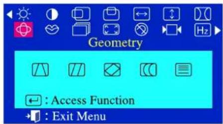
text_image
Geometry Access Function Exit Menu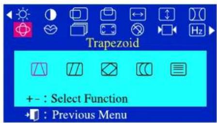
text_image
Trapezoid + - : Select Function →: Previous Menu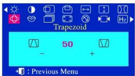
text_image
Trapezoid 50 + : Previous MenuTrapezoid
Adjust the trapezoid setting when the top or bottom of the display is too large or small.
1 With the menu off, push the menu ← button.
2 Push the - button or + button until the Geometry screen is displayed.
3 Push the menu ← button again and then press the - or + button until the Trapezoid screen appears.
Push the menu button to open the Trapezoid adjustment screen.
4 Use the - button or + button to adjust the trapezoid setting.
On Screen Display (OSD) Menu System
Menu How to adjust
text_image
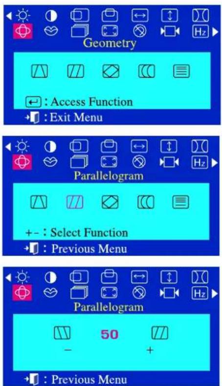
Geometry Access Function Exit Menu Parallelogram + - : Select Function Previous Menu Parallelogram 50 + Previous MenuParallelogram
Adjust the parallelogram setting when the display is leaning left or right.
1 With the menu off, push the menu ← button.
2 Push the - button or + button until the Geometry screen is displayed.
3 Push the menu ← button again and then press the - or + button until the Parallelogram screen appears.
Push the menu ← button to open the Parallelogram adjustment screen.
4 Use the - button or + button to adjust the parallel setting.
text_image
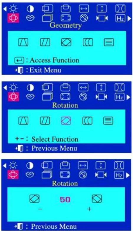
Geometry Access Function Exit Menu Rotation + - : Select Function Previous Menu Rotation 50 + Previous MenuRotation
Adjust the rotation setting when the entire display is tilted left or right.
1 With the menu off, push the menu ← button.
2 Push the - button or + button until the Geometry screen is displayed.
3 Push the menu ← button again and then press the - or + button until the Rotation screen appears.
Push the menu ← button to open the Rotation adjustment screen.
4 Use the - button or + button to adjust the rotation setting.
On Screen Display (OSD) Menu System
Menu How to adjust
text_image
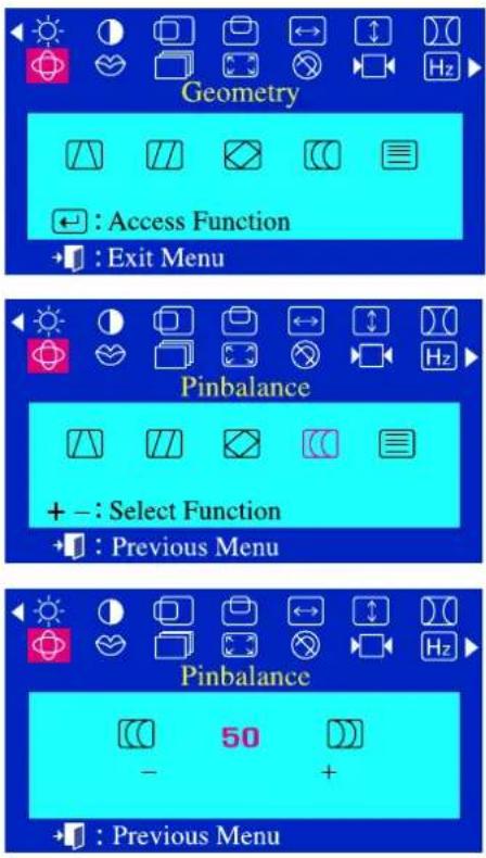
Geometry Access Function Exit Menu Pinbalance + - : Select Function Previous Menu Pinbalance 50 - +Pinbalance
Adjust the pinbalance setting when the sides of the display are bowed towards the left or right.
1 With the menu off, push the menu ← button.
2 Push the - button or + button until the Geometry screen is displayed.
3 Push the menu ← button again and then press the - or + button until the Pinbalance screen appears.
Push the menu ← button to open the Pinbalance adjustment screen.
4 Use the - button or + button to adjust the pinbalance setting.
text_image
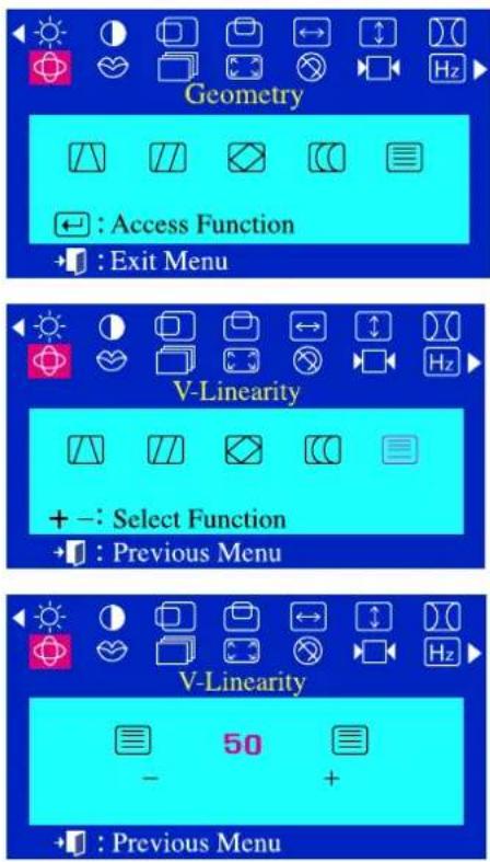
Geometry Access Function Exit Menu V-Linearity + -: Select Function Previous Menu V-Linearity 50 + Previous MenuV-Linearity
Adjust the linearity setting when the display image is compressed at the left, right or top, bottom.
1 With the menu off, push the menu← button.
2 Push the - button or + button until the Geometry screen is displayed.
3 Push the menu ← button.
Push the - button or + button until the V-Linearity screen is displayed.
Push the menu ← button to open the V-Linearity adjustment screen.
4 Use the - button or + button to adjust the vertical linearity.
On Screen Display (OSD) Menu System
Menu How to adjust
text_image
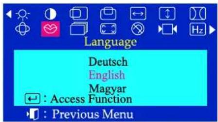
Language Deutsch English Magyar ← : Access Function → : Previous Menu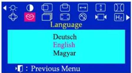
text_image
Language Deutsch English Magyar : Previous MenuLanguage
Follow these steps to change the language used in the menu. You can choose one of ten languages.
English, German, French, Italian, Portuguese, Spanish, Swedish, Russian, Polish, or Magyar.
(Some OSD languages may not appear in some areas.)
1 With the menu off, push the menu ← button.
2 Push the - button or + button until the Language screen is displayed.
3 Push the menu ← button to open the Language selection screen.
4 Use the - button or + button to select the language you would like to use.
Note The language chosen affects only the language of the OSD. It has no effect on any software running on the computer.
On Screen Display (OSD) Menu System
Menu How to adjust
text_image
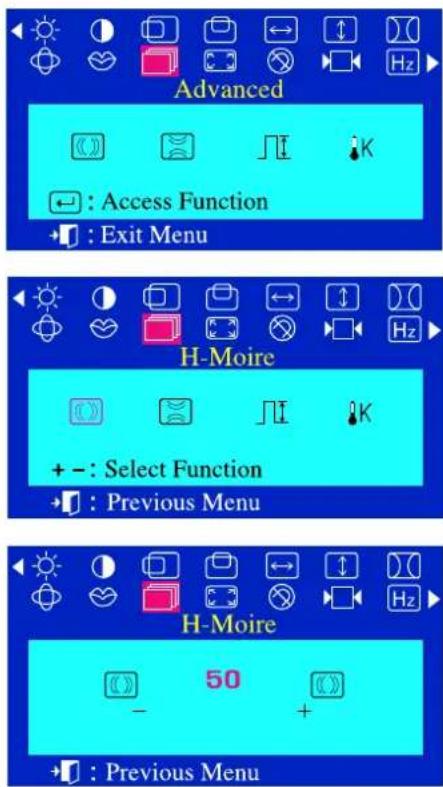
Advanced Access Function Exit Menu H-Moire + - : Select Function Previous Menu H-Moire 50 + Previous MenuH-Moire
A “Moiré” pattern can appear on your screen, looking like a series of concentric circles or arcs. To eliminate this pattern, use the clear moiré adjustments.
1 With the menu off, push the menu ← button.
2 Push the - button or + button until the Advanced screen is displayed.
3 Push the menu ← button again and then press the - or + button until the H-Moire screen appears.
Push the menu ← button to open the H-Moire
adjustment screen.
4 Use the - button or + button to adjust horizontal moiré.
text_image
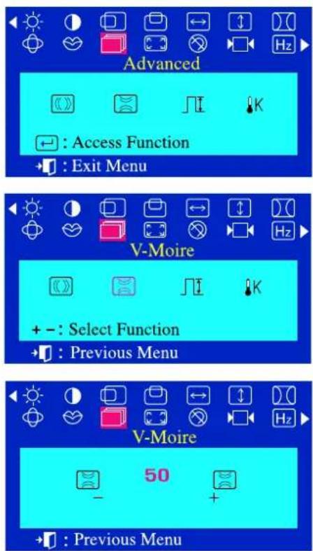
Advanced Access Function Exit Menu V-Moire + - : Select Function Previous Menu V-Moire 50 + Previous MenuV-Moire
A “Moiré” pattern can appear on your screen, looking like a series of concentric circles or arcs. To eliminate this pattern, use the clear moiré adjustments.
1 With the menu off, push the menu← button.
2 Push the - button or + button until the Advanced screen is displayed.
3 Push the menu ← button again and then press the - or + button until the V-Moire screen appears.
Push the menu ← button to open the V-Moire adjustment screen.
4 Use the - button or + button to adjust vertical moiré.
On Screen Display (OSD) Menu System
Menu How to adjust
text_image
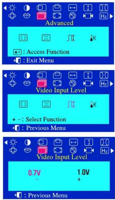
Advanced Access Function Exit Menu Video Input Level + - : Select Function Previous Menu Video Input Level 0.7V 1.0V - +Video Input Level
Some video cards use video signals higher than 1.0V which causes the display to be very bright. For those video cards, use this feature to select the 1.0V Level.
1 With the menu off, push the menu ← button.
2 Push the - button or +button until the Advanced screen is displayed.
3 Push the menu ← button again and then press the - or + button until the Video Input Level screen appears.
Push the menu ← button to open the Video Input Level selection screen.
4 Use the - button or + button to select 0.7 V or 1.0 V.
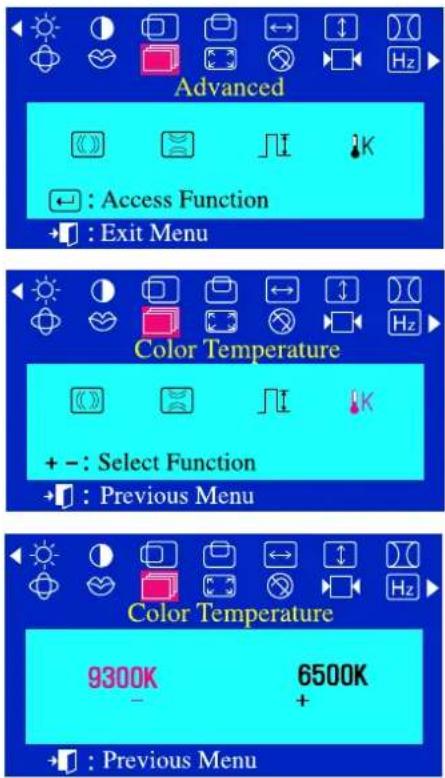
text_image
Advanced Access Function Exit Menu Color Temperature + - : Select Function Previous Menu Color Temperature 9300K 6500K - + Previous MenuColor Temperature
Color temperature is a measure of the "warmth" of the image colors. The available range is between 6500 to 9300K.
1 With the menu off, push the menu ← button.
2 Push the - button or + button until the Advanced screen is displayed.
3 Push the menu ← button again and then press the - or + button until the Color Temperature screen appears.
Push the menu ← button to open the Color Temperature selection screen.
4 Press the - or + button to select 9300K(Bluish colors) or 6500K(Reddish colors).
On Screen Display (OSD) Menu System
Menu How to adjust
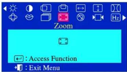
text_image
Zoom : Access Function : Exit Menu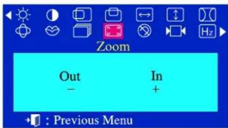
text_image
Zoom Out - In + →: Previous MenuZoom
Follow these instructions to get a close-up or a longshot view of the monitor's viewing area.
1 With the menu off, push the menu ← button.
2 Push the - button or + button until the Zoom screen is displayed.
3 Push the menu ← button to open the Zoom adjustment screen.
4 Use the - button to decrease the screen viewing area. Use the + button to enlarge the screen viewing area.
On Screen Display (OSD) Menu System
Menu How to adjust
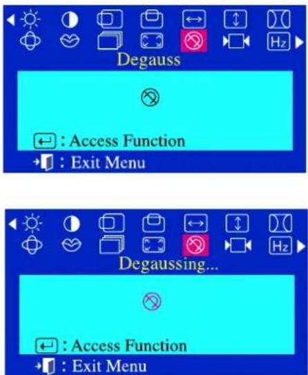
text_image
Degauss Access Function Exit Menu Degaussing... Access Function Exit MenuDegauss
The Degauss feature will remove color impurities caused by magnetic fields. You can use this function to turn on the power of the monitor or change the power saving mode to the normal mode. Do not use the Degauss feature more than once within a 30-minute period.
1 With the menu off, push the menu ← button.
2 Push the - button or + button until the Degauss screen is displayed.
3 Push the menu ← button to execute the degauss function. The degaussing screen will appear.
Note The monitor may buzz momentarily, the image colors may change and the image will jiggle for a few seconds. These effects are normal.
text_image
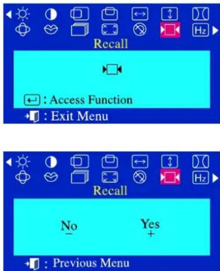
Recall Access Function Exit Menu Recall No Yes + Previous MenuRecall
Use the recall feature to reset these monitor settings to their original levels: Position, Size, Pincushion, Trapezoid, Parallelogram, Pinbalance, Rotation, H-Moire and V-Moire.
1 With the menu off, push the menu ← button.
2 Push the - button or + button until the Recall screen is displayed.
3 Push the menu ← button to open the Recall adjustment screen.
4 Push the + button to select Yes.
If you don't want to reset the monitor, use the - button to select No.
Note If you have selected "Yes", all settings listed above will be reset. All other settings will remain the same.
CAUTION This operation resets all of the data in the user memory area for the current timing signal.
On Screen Display (OSD) Menu System
Menu How to adjust
text_image
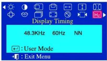
Display Timing 48.3KHz 60Hz NN ← : User Mode → : Exit Menu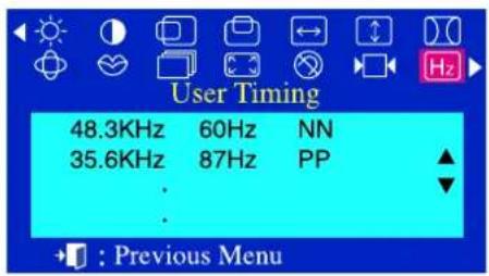
text_image
User Timing 48.3KHz 60Hz NN 35.6KHz 87Hz PP : Previous Menu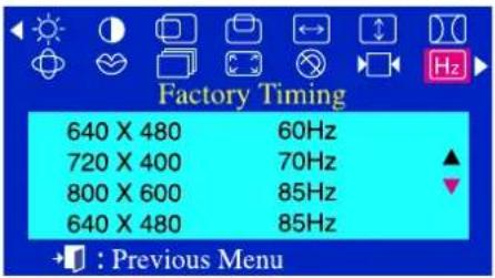
text_image
Factory Timing 640 X 480 60Hz 720 X 400 70Hz 800 X 600 85Hz 640 X 480 85Hz : Previous MenuDisplay Timing
The information on this screen shows Display Timing, User Timing and Factory Timing.
1 With the menu off, push the menu ← button.
2 Push the - button or + button until the Display Timing screen is displayed.
3 Push the menu ← button to open the Display Timing adjustment screen.
4 Use the - button to see user control mode and thedefault mode.
Note You can see the frequency(user control mode) used by the user, the polarity of the operational signals, the default frequency(default mode) set when you buy the monitor and the resolution level.
text_image
Control Lock Locked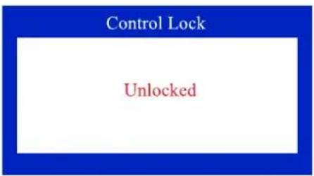
text_image
Control Lock UnlockedOSD Lock/Unlock
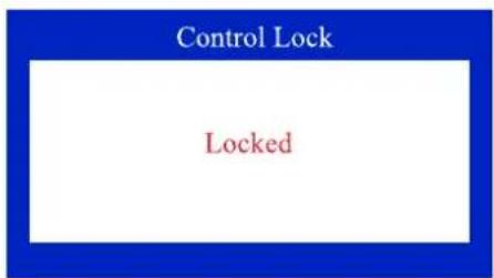
1 Push and hold in the menu ← button for 10 seconds or more to Lock the OSD.
(In this case, even if you click the menu ← button the control screen will not be printed.)
2 Push and hold in the menu ← button for 10 seconds or more to Unlock the OSD.

text_image
Index | Safety Instructions | Introduction | Setup | On-Screen Display | Troubleshooting | Specifications | Information Troubleshooting Note Before calling for service, check the information in this section to see if you can remedy any problems yourself. If you do need assistance, please call the phone number on the warranty card, the phone number on the Information section or contact your dealer.▶ Check List
Q & A
▶ Self-Test Feature Check
Main Page

Before calling for service, check the information in this section to see if you can remedy any problems yourself. If you do need assistance, please call the phone number on the warranty card, the phone number on the Information section or contact your dealer.
| Symptom Check List Solutions | ||
| No images on the screen. I cannot turn on the monitor. | Is the power cord connected properly? | Check the power cord connection and supply. |
| Can you see "No Connection, Check Signal Cable" on the screen? | Check the signal cable connection. | |
| If the power is on, reboot the computer to see the initial screen(the login screen), which can be seen. | If the initial screen (the login screen) appears, boot the computer in the applicable mode (the safe mode for Windows ME/XP/2000) and then change the frequency of the video card.(Refer to the Preset Timing Modes)Note: If the initial screen (the login screen) does not appear, contact a service center or your dealer. | |
| Can you see "Sync. Out of Range" on the screen? | You can see this message when the signal from the video card exceeds the maximum resolution and frequency that the monitor can properly handle.Adjust the maximum resolution and frequency that the monitor can properly handle. | |
| There is no image on the screen. Is the power indicator on the monitor blinking at 1 second intervals? | The monitor is in PowerSaver mode.Press a key on the keyboard or move the mouse to activate the monitor and restore the image on the screen. | |
| I cannot see the On Screen Display. | Have you locked the On Screen Display (OSD) Menu to prevent changes? | Unlock the OSD by pressing the MENU button for at least 10 seconds. |
| The image on the screen is shaking. | Check the monitor configuration to see if it is in Interlace Mode. (Interlace Mode: Vertical frequency 43Hz, 87Hz(i), etc) | The signal from the video card exceeds the maximum resolution and frequency of the monitor. |
| Are there any magnetic products such as a power adapter, speaker or a high voltage wire near by? | Move the monitor away from anything that can create a strong magnetic field. | |
| Is the voltage stable? The screen image can appear to shake or vibrate at a particular time of day due to low supply voltage. | ||
| The screen image can also appear to shake or vibrate if there is a problem with the video card or the computer's main board. | ||
| The screen shows strange colors or just black and white. | Is the screen displaying only one color as if looking at the screen through a cellophane paper? | Check the signal cable connection.Make sure the video card is fully inserted in it's slot. |
| Have the screen colors become strange after running a program or due to a crash between applications? | Reboot the computer. | |
| Has the video card been set properly? | Set the video card by referring to the video card manual. | |
| The screen suddenly has become unbalanced. | Have you changed the video card or the driver? | Adjust screen image position and size using the OSD. |
| Have you adjusted the resolution or frequency to the monitor? | Adjust the resolution and frequency at the video card.(Refer to the Preset Timing Modes). | |
| The screen can be unbalanced due to the cycle of the video card signals. Readjust Position by referring to the OSD. | ||
| The screen is out of focus or OSD cannot be adjusted. | Have you adjusted the resolution or frequency on the monitor? | Adjust the resolution and frequency of the video card.(Refer to the Preset Timing Modes). |
| The screen is partially distorted. | Are there any magnetic products such as an adapter, speaker or a high voltage wire near the monitor? | Enter the OSD and perform a "Degauss".Keep the monitor away from any magnetic products. |
| LED is blinking but no images on the screen. | Is the frequency properly adjusted when checking the Display Timing on the menu? | Adjust the frequency properly by referring to the video card manual and the Preset Timing Modes.(The maximum frequency per resolution may differ from product to product.) |
| There are only 16 colors shown on the screen. The screen colors have changed after changing the video card. | Have the Windows colors been set properly? | For Windows ME/XP/2000:Set the colors properly at the Control Panel, Display, Settings. |
| Has the video card been set properly? | Set the video card by referring to the video card manual. | |
| There is a message that reads "Unrecognized monitor, Plug & Play (VESA DDC) monitor found". | Have you installed the monitor driver? | Install the monitor driver according to the Driver Installation Instructions. |
| See the video card manual to see if the Plug & Play (VESA DDC) function can be supported. | Install the monitor driver according to the Driver Installation Instructions. | |
Check the following items if there is trouble with the monitor.
- Check if the power cord and the cable are properly connected to the computer.
- Check if the computer beeps more than 3 times when booting. (If it does, request an after-service for the main board of the computer.)
- If you installed a new video card or if you assembled the PC, check if the installed the adapter (video) driver and the monitor driver.
- Check if the scanning ratio of the video screen is set at 75Hz or 85Hz. (Do not exceed 60Hz when using the maximum resolution.)
- If you have problems in installing the adapter (video) driver, boot the computer in Safe Mode, remove the Display Adapter at the "Control Panel, System, Device Administrator" and then reboot the computer to reinstall the adapter (video) driver.
| Question Answer | |
| How can I change the frequency? Frequency can be changed by reconfiguring the video card. | |
| Note that video card support can vary, depending on the version of the driver used.(Refer to the computer or the video card manual for details.) | |
| Question Answer | |
| How can I change the frequency? Frequency can be changed by reconfiguring the video card.Note that video card support can vary, depending on the version of the driver used.(Refer to the computer or the video card manual for details.) | |
| How can I adjust the resolution? | Windows ME/XP/2000: Set the resolution at the Control Panel, Display, Settings.* Contact the video card manufacturer for details. |
| How can I set the Power Saving function? | Windows ME/XP/2000: Set the function at BIOS-SETUP of the computer or the screen saver. (Refer to Windows/Computer Manual). |
| The monitor makes a sound when it is turned on. | This is normal as some sound may be generated when the metal case and the electromagnet, which are installed to block any electromagnetic waves, interact with each other. |
| How can I clean the outer case/Picture tube? | Disconnect the power cord and then clean the monitor with a soft cloth, using either a cleaning solution or plain water.Do not leave any remains of the detergent nor scratch the case. Do not allow any water to go inside the monitor. |
Main Page
text_image
Index | Safety Instructions | Introduction | Setup | On-Screen Display | Troubleshooting | Specifications | Information Main > Troubleshooting > Self-Test Feature Check Self-Test Feature Check | Warning Messages | Environment | Useful Tips Troubleshooting ▶ Check List ▶ Q & A ▶ Self-Test Feature Check Main Page Your monitor provides a self test feature that allows you to check whether your monitor is functioning properly. ● Self-Test Feature Check 1. Turn off both your computer and the monitor. 2. Unplug the video cable from the back of the computer.Your monitor provides a self test feature that allows you to check whether your monitor is functioning properly.
Self-Test Feature Check
- Turn off both your computer and the monitor.
- Unplug the video cable from the back of the computer.
- Turn on the monitor.
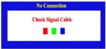
If your monitor works normally, the following screen appears.
text_image
No Connection Check Signal CableFailure of any of the boxes to appear indicates a problem with your monitor. This box also appears during normal operation if the video cable becomes disconnected or damaged.
- Turn off your monitor and reconnect the video cable; then turn on both your computer and the monitor.
If your monitor screen remains blank after using the previous procedure, check your video controller and computer system; your monitor is functioning properly.
Warning Messages
If there is something wrong with the input signal, a message appears on the screen or the screen goes blank although the power indicator LED is still on. The message may indicate that the monitor is out of scan range or that you need to check the signal cable.

text_image
Sync.Out of RangeEnvironment
The location and the position of the monitor may influence the quality and other features of the monitor.
- It there are any wooer speakers near the monitor, unplug and relocate the wooer to another room.
- Remove all electronic devices such as radios, fans, clocks and telephones that are within 3 feet (one meter) of the monitor.
- Degauss the monitor if any devices were removed from the area.

Useful Tips
- A monitor recreates visual signals received from the PC. Therefore, if there is trouble with the PC or the video card, this can cause the monitor to become blank, have poor coloring, noise, Sync. Out of Range, etc. In this case, first check the source of the problem, and then contact a service center or your dealer.
• Judging the monitor's working condition
If there is no image on the screen or an "Sync. Out of Range" message comes up, disconnect the cable from the computer while the monitor is still powered on.
○ If there is a message coming up on the screen or if the screen goes white, this means the monitor is in working condition.
o In this case, check the computer for trouble.
| Index | Safety Instructions | Introduction | Setup | On-Screen Display | Troubleshooting | Specifications | Information |
 | |||||||
| Specifications | |||||||
| ▶ General | |||||||
| ▶ PowerSaver | |||||||
| ▶ Preset Timing Modes | |||||||
| Main Page | |||||||
Main Page
General
Picture Tube
Screen type Aluminized tri-color phosphor dot trio with black matrix.
Anti-doming invar shadow mask.
Multi-layer coated with anti-static.
Maximum Resolution
1600 Dots, 1200 Lines
Active Display
Horizontal 352 ± 3 mm
Vertical 264 ± 3 mm
Synchronization
Horizontal 30 \~ 85 kHz
Vertical 50 \~ 160 Hz
Input Signal Definition
Video Signal RGB, Analog 0.7 Vpp positive at 75 ohms
Sync Signal Separate H/V sync, TTL level, positive or negative
Display Color
Unlimited
Maximum Pixel Clock
185 MHz
Power Supply
90 \~ 264VAC rms, 60/50 Hz ± 3Hz
Power Consumption
110W (Maximum), 100W (Nominal)
Dimensions (WxDxH)
440 x 459 x 455 mm (with Stand)
Weight
22.0 kg
Environmental considerations
Operating Temperature 32°F \~ 104°F(0°C \~ 40°C)
Humidity 10% \~ 80%, non-condensing
Storage Temperature -4°F \~113°F (-20°C \~ 45°C)
Humidity 5% \~ 95%, non-condensing
Plug and Play Capability
This monitor can be installed on any Plug & Play compatible system. Interaction of the monitor and computer systems will provide the best operating conditions and monitor settings. In most cases, monitor installation will proceed automatically, unless the user wishes to select alternate settings.
Note: Design and specifications are subject to change without prior notice.
| Index | Safety Instructions | Introduction | Setup | On-Screen Display | Troubleshooting | Specifications | Information |
| |||||||
| Specifications | |||||||
| ▶ General | |||||||
| ▶ PowerSaver | |||||||
| ▶ Preset Timing Modes | |||||||
| Main Page | |||||||
Main Page
General
Picture Tube
Screen type Aluminized tri-color phosphor dot trio with black matrix.
Anti-doming invar shadow mask.
Multi-layer coated with anti-static.
Maximum Resolution
1600 Dots, 1200 Lines
Active Display
Horizontal 352 ± 3 mm
Vertical 264 ± 3 mm
Synchronization
Horizontal 30 \~ 85 kHz
Vertical 50 \~ 160 Hz
Input Signal Definition
Video Signal RGB, Analog 0.7 Vpp positive at 75 ohms
Sync Signal Separate H/V sync, TTL level, positive or negative
Display Color
Unlimited
Maximum Pixel Clock
185 MHz
Power Supply
90 \~ 264VAC rms, 60/50 Hz ± 3Hz
Power Consumption
110W (Maximum), 100W (Nominal)
Dimensions (WxDxH)
440 x 459 x 455 mm (with Stand)
Weight
22.0 kg
Environmental considerations
Operating Temperature 32°F \~ 104°F(0°C \~ 40°C)
Humidity 10% \~ 80%, non-condensing
Storage Temperature -4°F \~113°F (-20°C \~ 45°C)
Humidity 5% \~ 95%, non-condensing
Plug and Play Capability
This monitor can be installed on any Plug & Play compatible system. Interaction of the monitor and computer systems will provide the best operating conditions and monitor settings. In most cases, monitor installation will proceed automatically, unless the user wishes to select alternate settings.
Note: Design and specifications are subject to change without prior notice.
Specifications
General
PowerSaver
▶ Preset Timing Modes
Main Page
This monitor has a built-in power management system called PowerSaver. This system saves energy by switching your monitor into a low-power mode when it has not been used for a certain amount of time. The monitor automatically returns to normal operation when you move the computer's mouse or press a key on the keyboard. For energy conservation, turn your monitor OFF when it is not needed, or when leaving it unattended for long periods. The PowerSaver system operates with a VESA DPMS compliant video card installed in your computer. Use a software utility installed on your computer to set up this feature.
| State Normal Operation | Power-off Mode EPA/ENERGY 2000 | |
| Power Indicator Green Green, Blinking | ||
| Power Consumption | 100W(Nominal)110W(Maximum) | Less than 2W |

This monitor is EPA ENERGY STAR® compliant and ENERGY2000 compliant when used with a computer equipped with VESA DPMS functionality.
As an ENERGY STAR ^® Partner, SAMSUNG has determined that this product meets the ENERGY STAR ^® guidelines for energy efficiency.
text_image
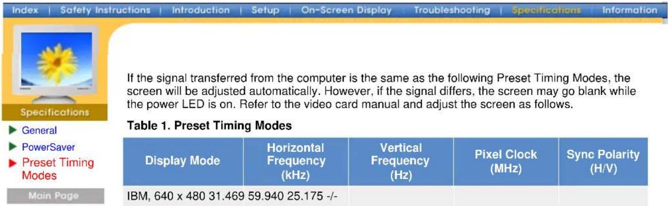
If the signal transferred from the computer is the same as the following Preset Timing Modes, the screen will be adjusted automatically. However, if the signal differs, the screen may go blank while the power LED is on. Refer to the video card manual and adjust the screen as follows. Table 1. Preset Timing Modes Display Mode Horizontal Frequency (kHz) Vertical Frequency (Hz) Pixel Clock (MHz) Sync Polarity (H/V) IBM, 640 x 480 31.469 59.940 25.175 -/-If the signal transferred from the computer is the same as the following Preset Timing Modes, the screen will be adjusted automatically. However, if the signal differs, the screen may go blank while the power LED is on. Refer to the video card manual and adjust the screen as follows.
Table 1. Preset Timing Modes
| Display Mode | Horizontal Frequency (kHz) | Vertical Frequency (Hz) | Pixel Clock (MHz) | Sync Polarity (H/V) |
| IBM, 640 x 480 31.469 | 59.940 25.175 -/- | |||
| IBM, 720 x 400 31.469 | 70.087 28.322 -/+ | |||
| VESA, 640 x 480 37.500 | 75.000 31.500 -/- | |||
| VESA, 640 x 480 43.269 | 85.008 36.000 -/- | |||
| VESA, 800 x 600 | 53.674 85.061 | 56.250 +/+ | ||
| VESA, 1024 x 768 | 60.023 | 75.029 | 78.750 +/+ | |
| VESA, 1024 x 768 | 68.677 | 84.997 | 94.500 +/+ | |
| VESA, 1280 x 1024 | 79.976 | 75.025 | 135.00 +/+ |

Horizontal Frequency
The time to scan one line connecting the right edge to the left edge of the screen horizontally is called Horizontal Cycle and the inverse number of the Horizontal Cycle is called Horizontal Frequency. Unit: kHz
Vertical Frequency
Like a fluorescent lamp, the screen has to repeat the same image many times per second to display an image to the user. The frequency of this repetition is called Vertical Frequency or Refresh Rate. Unit: Hz
text_image
Index | Safety Instructions | Introduction | Setup | On-Screen Display | Troubleshooting | Specifications | Information Information ► Service ► Terms ► Regulatory ► Authority Main Page ● SAMTRON SEOUL 15TH FL, JOONGANG DAILY NEWS BLDG. 7, SOONHWA-DONG,CHUNG-KU, SEOUL, KOREA, 100-759 TEL : (82-2) 727-3114 ● SAMTRON U.S.A. SAMTRON COMPUTER PRODUCTS CUSTOMER SERVICE 400 Valley Road Suite 201, Mt. Arlington, NJ 07856 TEL : 973-601-6200, FAX : 973-601-6001 1-800-SAMTRON (1-800-726-8766)SAMTRON CANADA
SAMSUNG ELECTRONICS CANADA INC. 7037 FINANCIAL DRIVE MISSISSAUGA, ONTARIO L5N 6R3 TEL : 1-800-726-7864 FAX : 905-542-1199
SAMTRON EUROPE
SAMSUNG ELECTRONICS GMBH SAMSUNG-HAUS, AM KRONBERGER HANG 6 65824 SCHWALBACH/TS., GERMANY TEL: 49 (0180) 5121213* FAX: 49 (0180) 5121214* * EURO 0,12/MIN.
SAMTRON TOKYO
17TH, HAMACHO CENTER BLDG. 2-31-1, NIHONBASHI-HAMACHO, CHOU-KU, TOKYO 103, JAPAN TEL : (81-3) 5641-9860 FAX : (81-3) 5641-9861
SAMTRON SWEDEN
SAMSUNG ELECTRONICS SYENSKA, AB BOX 713, S- 194 27 UPPLANDS VÄSBY TEL : 468- 590- 966- 00 FAX : 468- 590- 966- 50
SAMTRON MEXICO
SAMSUNG ELECTRONICS MEXICO, S.A. DE C. V. Mina No. 200, ESQ. GAVILANCOL. GUADALUPE DEL MORAL IZTAPALAPA, MEXICO, D.F. C.P. 09300 TEL.: (525) 686-0800 FAX: (525) 686-5094
IMPORTADO POR: SAMSUNG ELECTRONICS MEXICO S.A. DE C.V. SATURNO 44 COL. NVA. INDUSTRIAL VALLEJO DEL. GUSTAVO A. MADERO C.P. 07700 MEXICO D.F. TEL. 5747-5100 RFC: SEM950215S98 EXPORTADO POR: SAMSUNG ELECTRONICS CO.,LTD. JOONG-ANG DAILY NEWS BLDG. 7 SOON-WHA-DONG CHUNG-KU, C.P.O BOX 2775, 1144 SEOUL, KOREA
Service
Terms
Regulatory
▶ Authority
Main Page
Information
Service
Terms
Regulatory
▶ Authority
Main Page
Information > Terms
Dot Pitch
The image on a monitor is composed of red, green and blue dots. The closer the dots, the higher the resolution. The distance between two dots of the same color is called the 'Dot Pitch'. Unit: mm
• Vertical Frequency
The screen must be redrawn several times per second in order to create and display an image for the user. The frequency of this repetition per second is called Vertical Frequency or Refresh Rate. Unit: Hz
Example: If the same light repeats itself 60 times per second, this is regarded as 60 Hz. In this case, flickering of the screen can be detected. To avoid this problem, there is a Flicker-free Mode using a vertical frequency over 70 Hz.
Horizontal Frequency
The time to scan one line connecting the right edge to the left edge of the screen horizontally is called Horizontal Cycle. The inverse number of the Horizontal Cycle is called Horizontal Frequency. Unit: kHz
• Interlace and Non-Interlace Methods
Showing the horizontal lines of the screen from the top to the bottom in order is called the Non-Interlace method while showing odd lines and then even lines in turn is called the Interlace method. The Non-Interlace method is used for the majority of monitors to ensure a clear image. The Interlace method is the same as that used in TVs.
Plug & Play
This is a function that provides the best quality screen for the user by allowing the computer and the monitor to exchange information automatically. This monitor follows the international standard VESA DDC for the Plug & Play function.
Resolution
The number of horizontal and vertical dots used to compose the screen image is called 'resolution'. This number shows the accuracy of the display. High resolution is good for performing multiple tasks as more image information can be shown on the screen.
Example: If the resolution is 1024 X 768, this means the screen is composed of 1024 horizontal dots (horizontal resolution) and 768 vertical lines (vertical resolution).
text_image
Main > Information > Regulatory FCC Information | IC Compliance Notice | MPR II Compliance | European Notice (Europe only) | PCT Notice | VCCI | TCO'95-Ecological requirements for personal computers (TCO applied model only) TCO'99-Ecological requirements for personal computers (TCO applied model only) ● FCC Information User Instructions The Federal Communications Commission Radio Frequency Interference Statement includes the following warning:Note: This equipment has been tested and found to comply with the limits for a Class B digital device, pursuant to Part 15 of the FCC Rules. These limits are designed to provide reasonable protection against harmful interference in a residential installation. This equipment generates, uses, and can radiate radio frequency energy and, if not installed and used in accordance with the instructions, may cause harmful interference to radio communications. However, there is no guarantee that interference will not occur in a particular installation. If this equipment does cause harmful interference to radio or television receptions, which can be determined by turning the equipment off and on, the user is encouraged to try to correct the interference by one or more of the following measures:
• Reorient or relocate the receiving antenna.
- Increase the separation between the equipment and receiver.
- Connect the equipment into an outlet on a circuit different from that to which the receiver is connected.
- Consult the dealer or an experienced radio/TV technician for help.
User Information
Changes or modifications not expressly approved by the party responsible for compliance could void the user's authority to operate the equipment. If necessary, consult your dealer or an experienced radio/television technician for additional suggestions. You may find the booklet called How to Identify and Resolve Radio/TV Interference Problems helpful. This booklet was prepared by the Federal Communications Commission. It is available from the U.S. Government Printing Office, Washington, DC 20402, Stock Number 004-000-00345-4.
The party responsible for product compliance:
SAMSUNG ELECTRONICS CO., LTD
America QA Lab of Samsung
3351 Michelson Drive,
Suite #290, Irvine, CA92612 USA
Tel) 949-975-7310
Fax) 949-922-8301
Warning
User must use shielded signal interface cables to maintain FCC compliance for the product.
Provided with this monitor is a detachable power supply cord with IEC320 style terminations. It may be suitable for connection to any UL Listed personal computer with similar configuration. Before making the connection, make sure the voltage rating of the computer convenience outlet is the same as the monitor and that the ampere rating of the computer convenience outlet is equal to or exceeds the monitor voltage rating.
For 120 Volt applications, use only UL Listed detachable power cord with NEMA configuration 5-15P type (parallel blades) plug cap. For 240 Volt applications use only UL Listed Detachable power supply cord with NEMA configuration 6-15P type (tandem blades) plug cap.
IC Compliance Notice
This Class B digital apparatus meets all requirements of the Canadian Interference-Causing Equipment Regulations of ICES-003.
This monitor complies with SWEDAC(MPR II) recommendations for reduced electric and magnetic fields.
• European Notice (Europe only)
Products with the CE Marking comply with both the EMC Directive (89/336/EEC), (92/31/EEC), (93/68/EEC) and the Low Voltage Directive (73/23/EEC) issued by the Commission of the European Community.
Compliance with these directives implies conformity to the following European Norms:
• EN55022:1998 - Radio Frequency Interference
• EN55024:1998 - Electromagnetic Immunity
• EN61000-3-2:1995+A1+A2 - Power Line Harmonics
• EN61000-3-3:1995 - Voltage Fluctuations
• EN60950 - Product Safety.
PCT Notice

АЯ46
VCCI
This is a Class B product based on the standard of the Voluntary Control Council for Interference by Information Technology Equipment (VCCI). If this is used near a radio or television receiver in a domestic environment, it may cause radio interference. Install and use the equipment according to the instruction manual.
TCO'95-Ecological requirements for personal computers (TCO applied model only)

AB general requirements
AB2 Written Eco-document accompanying the products
Congratulations! You have just purchased a TCO'95 approved and labelled product! Your choice has provided you with a product developed for professional use. Your purchase has also contributed to reducing the burden on the environment and to the further development of environmentally-adapted electronic products.
Why do we have environmentally-labelled monitors?
In many countries, environmental labelling has become an established method for encouraging the adaptation of goods and services to the environment. The main problem as far as monitors and other electronic equipment are concerned is that environmentally harmful substances are used both in the products and during their manufacture. Since it has not been possible so far for the majority of electronic equipment to be recycled in a satisfactory way, most of these potentially damaging substances sooner or later enter Nature.
There are also other characteristics of a monitor, such as energy consumption levels, that are important from both the working and natural environment viewpoints. Since all types of conventional electricity generation have a negative effect on the environment (acidic and climate-influencing emissions, radioactive waste, etc.) it is vital to conserve energy. Electronic equipment in offices consumes an enormous amount of energy, since it is often routinely left running continuously.
What does labelling involve?
This product meets the requirements for the TCO'95 scheme, which provides for international environmental labelling of monitors. The labelling scheme was developed as a joint effort by the TCO (The Swedish Confederation of Professional Employees), Naturskyddsforeningen (The Swedish Society for Nature Conservation) and NUTEK (The National Board for Industrial and Technical Development in Sweden).
The requirements cover a wide range of issues: environment, ergonomics, usability, emission of electrical and magnetic fields, energy consumption and electrical and fire safety.
The environmental demands concern among other things restrictions on the presence and use of heavy metals, brominated and chlorinated flame retardants, CFCs (freons), and chlorinated solvents. The product must be prepared for recycling and the manufacturer is obliged to have an environmental plan, which must be adhered to in each country where the company conducts its operations policy. The energy requirements include a demand that the monitor after a certain period of inactivity shall reduce its power consumption to a lower level, in one or more stages. The length of time to reactivate the monitor shall be reasonable for the user.
Labelled products must meet strict environmental demands, for example in respect of the reduction of electric and magnetic fields, along with physical and visual ergonomics and good usability.
TCO Development Unit 1996-11-29
On the page this folder you will find a brief summary of the environmental requirements met by this product.
The compleere environmental criteria document may be ordered from:
TCO Development Unit
S-11494 Stockholm
Sweden
Fax: +46 8 782 92 07
E-mail (Internet): development@tco.se
Current information regarding TCO'95-approved and labelled products may also be obtained via the Internet, using the address:
http://www.tco-info.com/
TCO'95 is a co-operative project between(3 logos)
Environmental Requirements
Brominated flame retardants are present in printed circuit boards, cables, wires, casings and housings. In turn, they delay the spread of fire. Up to thirty percent of the plastic in a computer casing can consist of flame retardant substances. These are related to another group of environmental toxins, PCBs, which are suspected to give rise to similar harm, including reproductive damage in fish eating birds and mammals, due to the bioaccumulative processes. Flame retardants have been found in human blood and researchers fear that disturbances in foetus development may occur.
- TCO'95 demand requires that plastic components weighing more than 25 grams must not contain organically bound chlorine and bromine.
Lead
Lead can be found in picture tubes, display screens, solders and capacitors. Lead damages the nervous system and in higher doses, causes lead poisoning.
- TCO'95 requirement Permits the inclusion of lead since no replacement has yet been developed.
Cadmium
Cadmium is present in rechargeable batteries and in the colour generating layers of certain computer displays. Cadmium damages the nervous system and is toxic in high doses.
- TCO'95 requirement states that batteries may not contain more than 25 ppm (parts per million) of cadmium. The colour-generating layers of display screens must not contain any cadmium.
Mercury
Mercury is sometimes found in batteries, relays and switches. Mercury damages the nervous system and is toxic in high doses.
- TCO'95 requirement states that batteries may not contain more than 25 ppm (parts per million) of mercury. It also demands that no mercury is present in any of the electrical or electronics components concerned with the display unit.
CFCs (freons)
CFCs (freons) are sometimes used for washing printed circuit boards and in the manufacturing of expanded foam for packaging. CFCs break down ozone and thereby damage the ozone layer in the stratosphere, causing increased reception on Earth of ultraviolet light with consequent increased risks of skin cancer (malignant melanoma).
- The relevant TCO'95 requirement: Neither CFCs nor HCFCs may be used during the manufacturing of the product or its packaging.
TCO'99-Ecological requirements for personal computers (TCO applied model only)

Congratulations!
You have just purchased a TCO'99 approved and labelled product! Your choice has provided you with a product developed for professional use. Your purchase has also contributed to reducing the burden on the environment and also to the further development of environmentally adapted electronics products.
This product meets the requirements for the TCO'99 scheme which provides for an international environmental and quality labelling labelling of personal computers. The labelling scheme was developed as a joint effort by the TCO(The Swedish Confederation of Professional Employees), Svenska Naturskyddsforeningen(The Swedish Society for Nature Conservation), Statens Energimydighet(The Swedish National Energy Administration) and SEMKO AB.
The requirements cover a wide range of issue: environment, ergonomics, usability, reduction of electric and magnetic fields, energy consumption and electrical safety.
Why do we have environmentally labelled computers?
In many countries, environmental labelling has become an established method for encouraging the adaptation of goods and services to the environment. The main problem, as far as computers and other electronics equipment are concerned, is that environmentally harmful substances are used both in the products and during their manufacture. Since it is not so far possible to satisfactorily recycle the majority of electronics equipment, most of these potentially damaging substances sooner or later enter nature.
There are also other characteristics of a computer, such as energy consumption levels, that are important from the viewpoints of both the work (internal) and natural (external) environments. Since all methods of electricity generation have a negative effect on the environment (e.g. acidic and climate-influencing emissions, radioactive waste), it is vital to save energy. Electronics equipment in offices is often left running continuously and thereby consumes a lot of energy.
What does labelling involve?
The environmental demands has been developed by Svenska Naturskyddsforeningen (The Swedish Society for Nature Conservation). These demands impose restrictions on the presence and use of heavy metals, brominated and chlorinated flame retardants, CFCs(freons)and chlorinated solvents, among other things. The product must be prepared for recycling and the manufacturer is obliged to have an environmental policy which must be adhered to in each country where the company implements its operational policy.
The energy requirements include a demand that the computer and/or display, after a certain period of inactivity, shall reduce its power consumption to a lower level in one or more stages. The length of time to reactivate the computer shall be reasonable for the user.
Below you will find a brief summary of the environmental requirements met by this product. The complete environmental criteria document may be ordered from:
TCO Development
SE-114 94 Stockholm, Sweden
Fax: +46 8 782 92 07
Email (Internet): development@tco.se
Current information regarding TCO'99 approved and labelled products may also be obtained via the Internet, using the address: http://www.tco-info.com/
Environmental requirements
Flame retardants
Flame retardants are present in printed circuit boards, cables, wires, casings and housings. Their purpose is to prevent, or at least to delay the spread of fire. Up to 30% of the plastic in a computer casing can consist of flame retardant substances. Most flame retardants contain bromine or chloride, and those flame retardants are chemically related to another group of environmental toxins, PCBs. Both the flame retardants containing bromine or chloride and the PCBs are suspected of giving rise to severe health effects, including reproductive damage in fish-eating birds and mammals, due to the bio-accumulative* processes. Flame retardants have been found in human blood and researchers fear that disturbances in foetus development may occur.
The relevant TCO'99 demand requires that plastic components weighing more than 25 grams must not contain flame retardants with organically bound bromine or chlorine. Flame retardants are allowed in the printed circuit boards since no substitutes are available.
Cadmium\*\*
Cadmium is present in rechargeable batteries and in the colour-generating layers of certain computer displays. Cadmium damages the nervous system and is toxic in high doses. The relevant TCO'99 requirement states that batteries, the colour-generating layers of display screens and the electrical or electronics components must not contain any cadmium.
Mercury\*\*
Mercury is sometimes found in batteries, relays and switches. It damages the nervous system and is toxic in high doses. The relevant TCO'99 requirement states that batteries may not contain any mercury. It also demands that mercury is not present in any of the electrical or electronics components associated with the labelled unit. There is however one exception. Mercury is, for the time being, permitted in the back light system of flat panel monitors as today there is no commercially available alternative. TCO aims on removing this exception when a Mercury free alternative is available.
CFCs (freons)
The relevant TCO'99 requirement states that neither CFCs nor HCFCs may be used during the manufacture and assembly of the product. CFCs (freons) are sometimes used for washing printed circuit boards. CFCs break down ozone and thereby damage the ozone layer in the stratosphere, causing increased reception on earth of ultraviolet light with e.g. increased risks of skin cancer (malignant melanoma) as a consequence.
Lead\*\*
Lead can be found in picture tubes, display screens, solders and capacitors. Lead damages the nervous system and in higher doses, causes lead poisoning. The relevant TCO'99 requirement permits the inclusion of lead since no replacement has yet been developed.
text_image
Index | Safety Instructions | Introduction | Setup | On-Screen Display | Troubleshooting | Specifications | Information Information Service Terms Regulatory Authority Main Page Information in this document is subject to change without notice. © 2002 Samsung Electronics Co., Ltd. All rights reserved. Reproduction in any manner whatsoever without the written permission of Samsung Electronics Co., Ltd. is strictly forbidden. Samsung Electronics Co., Ltd. shall not be liable for errors contained herein or for incidental or consequential damages in connection with the furnishing, performance, or use of this material. The Samsung logo and Samtron are registered trademarks of Samsung Electronics Co., Ltd.; Microsoft & Microsoft Windows NT Services (Wired) and Microsoft Windows NT Services (Wired)Information in this document is subject to change without notice.
© 2002 Samsung Electronics Co., Ltd. All rights reserved.
Reproduction in any manner whatsoever without the written permission of Samsung Electronics Co., Ltd. is strictly forbidden.
Samsung Electronics Co., Ltd. shall not be liable for errors contained herein or for incidental or consequential damages in connection with the furnishing, performance, or use of this material.
The Samsung logo and Samtron are registered trademarks of Samsung Electronics Co., Ltd.; Microsoft, Windows and Windows NT are registered trademarks of Microsoft Corporation; VESA, DPMS and DDC are registered trademarks of Video Electronics Standard Association; the ENERGY STAR name and logo are registered trademarks of the U.S. Environmental Protection Agency (EPA). As an ENERGY STAR Partner, Samsung Electronics Co., Ltd. has determined that this product meets the ENERGY STAR guidelines for energy efficiency. All other product names mentioned herein may be the trademarks or registered trademarks of their respective owners.