
UAA3000R32-19 - Air conditioner Universal Blue - Free user manual and instructions
Find the device manual for free UAA3000R32-19 Universal Blue in PDF.


| Product Type | Split air conditioner (inverter) |
| Model | UAA3000R32-19 |
| Energy Class | A++ |
| Refrigerant | R32 |
| Cooling Capacity | 1000-3770 W |
| Heating Capacity | 1000-3810 W |
| Power Consumption (Cooling) | 290-1320 W |
| Power Consumption (Heating) | 290-1400 W |
| SEER | 6.5 W/W |
| SCOP | 4 W/W |
| Air Flow Rate | 550 m³/h |
| Indoor Unit Noise Level | 32-50 dB(A) |
| Outdoor Unit Noise Level | 60 dB(A) |
| Indoor Unit Dimensions (WxHxD) | 777 x 205 x 250 mm |
| Outdoor Unit Dimensions (WxHxD) | 715 x 492 x 240 mm |
| Recommended Room Area | 14-22 m² |
| Compressor Type | Rotary (DC inverter) |
| Gas Connection Size (Liquid/Gas) | 1/4" / 3/8" |
| Control | Remote control with LCD display |
| Functions | Cool, Heat, Dry, Fan, Feel, Sleep, Turbo, Eco, Timer, Swing, Health |
| Filter | Washable air filter (optional odor filter) |
| Installation | Professional installation required; refrigerant pre-charged for 3 m |
| Power Supply | 220-240 V ~ 50 Hz (typical) |
Frequently Asked Questions - UAA3000R32-19 Universal Blue
User questions about UAA3000R32-19 Universal Blue
0 question about this device. Answer the ones you know or ask your own.
Ask a new question about this device
Download the instructions for your Air conditioner in PDF format for free! Find your manual UAA3000R32-19 - Universal Blue and take your electronic device back in hand. On this page are published all the documents necessary for the use of your device. UAA3000R32-19 by Universal Blue.
USER MANUAL UAA3000R32-19 Universal Blue
UAA3000R32-19, UAA4600R32-19, UAA6000R32-19
natural_image
Front view of a generic Siemens air conditioner unit with a digital display showing 26.9 degrees (no text or symbols on the device itself)natural_image
Diagram showing two electronic component assemblies with a switch and battery, no text or symbols present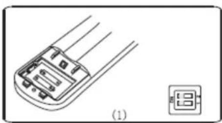
natural_image
Technical line drawing of a component with three parallel wires and a small inset showing a 18-pin connector (no text or symbols)
EMERGENCIA:
Table GG.1 – Maximum charge (kg)
| Category | LFL(kg/m3) | h0 (m) | Floor area (m2) | ||||||
| 4 | 7 | 10 | 15 | 20 | 30 | 50 | |||
| R290 | 0.038 | 0.6 | 0.05 | 0.07 | 0.08 | 0.1 | 0.11 | 0.14 | 0.18 |
| 1 | 0.08 | 0.11 | 0.13 | 0.16 | 0.19 | 0.2 | 0.3 | ||
| 1.8 | 0.15 | 0.2 | 0.24 | 0.29 | 0.34 | 0.41 | 0.53 | ||
| 2.2 | 0.18 | 0.24 | 0.29 | 0.36 | 0.41 | 0.51 | 0.65 | ||
| R32 | 0.306 | 0.6 | 0.68 | 0.9 | 1.08 | 1.32 | 1.53 | 1.87 | 2.41 |
| 1 | 1.14 | 1.51 | 1.8 | 2.2 | 2.54 | 3.12 | 4.02 | ||
| 1.8 | 2.05 | 2.71 | 3.24 | 3.97 | 4.58 | 5.61 | 7.254 | ||
| 2.2 | 2.5 | 3.31 | 3.96 | 4.85 | 5.6 | 6.86 | 8.85 | ||
Table GG.2 - Minimum room area (2)
| Category | LFL(kg/m3) | h0 (m) | Charge amount (M) (kg)Minimum room area (m2) | ||||||
| R290 | 0.038 | 0.152kg | 0.228 kg | 0.304 kg | 0.456 kg | 0.608 kg | 0.76 kg | 0.988 kg | |
| 0.6 | 82 | 146 | 328 | 584 | 912 | 1514 | |||
| 1 | 30 | 53 | 118 | 210 | 328 | 555 | |||
| 1.8 | 9 | 16 | 36 | 65 | 101 | 171 | |||
| 2.2 | 6 | 11 | 24 | 43 | 68 | 115 | |||
| R32 | 0.306 | 1.224 kg | 1.836 kg | 2.448 kg | 3.672 kg | 4.896 kg | 6.12 kg | 7.956 kg | |
| 0.6 | 29 | 51 | 116 | 206 | 321 | 543 | |||
| 1 | 10 | 19 | 42 | 74 | 116 | 196 | |||
| 1.8 | 3 | 6 | 13 | 23 | 36 | 60 | |||
| 2.2 | 2 | 4 | 9 | 15 | 24 | 40 | |||
flowchart
graph TD
    A["Indoor unit"] --> B["Refrigerant flow direction"]
    B --> C["3-way valve"]
    C --> D["Service port nut"]
    D --> E["Valve cap"]
    E --> F["(1) Turn"]
    E --> G["(2) Turn"]
    E --> H["(8) Tighten"]
    I["2-way valve"] --> J["(6) Open 1/4 turn"]
    I --> K["(7) Turn to fully open the valve"]
    I --> L["(1) Turn"]
    I --> M["(8) Tighten"]
    N["valve cap"] --> O["(1) Turn"]
    N --> P["(8) Tighten"]
| MODEL capacity (Btu/h) | 5k | 7k | 9k | 12k | 15/18k | 22/24k | 28/30k/36k | |
| sectional area | ||||||||
| Power supply cable | N | 1.0mm2 AWG18 | 1.0mm2 AWG18 | 1.0mm2 AWG18 | 1.0mm2(1.5mm2) AWG18(AWG16) | 1.5mm2 AWG16 | 2.5mm2 AWG14H05RN-F | 4.0mm2 AWG12 |
| L | 1.0mm2 AWG18 | 1.0mm2 AWG18 | 1.0mm2 AWG18 | 1.0mm2(1.5mm2) AWG18(AWG16) | 1.5mm2 AWG16 | 2.5mm2 AWG14H05RN-F | 4.0mm2 AWG12 | |
| E | 1.0mm2 AWG18 | 1.0mm2 AWG18 | 1.0mm2 AWG18 | 1.0mm2(1.5mm2) AWG18(AWG16) | 1.5mm2 AWG16 | 2.5mm2 awG14H05RN-F | 4.0mm2 AWG12 | |
| Connection supply cable | N | 1.0mm2 | 1.0mm2 | 1.0mm2 | 1.0mm2(1.5mm2) | 1.5mm2 | 0.75mm2 | 0.75mm2 |
| L | 1.0mm2 | 1.0mm2 | 1.0mm2 | 1.0mm2(1.5mm2) | 1.5mm2 | 0.75mm2 | 0.75mm2 | |
| 1 | 1.0mm2 | 1.0mm2 | 1.0mm2 | 1.0mm2(1.5mm2) | 1.5mm2 | 0.75mm2 | 0.75mm2 | |
| 2 | 0.75mm2 | 0.75mm2 | 0.75mm2 | 0.75mm2 | 0.75mm2 | 0.75mm2 | 0.75mm2 | |
| 3 | 0.75mm2 | 0.75mm2 | 0.75mm2 | 0.75mm2 | 0.75mm2 | 0.75mm2 | 0.75mm2 | |
| 0.75mm2 | 0.75mm2 | 0.75mm2 | 0.75mm2 | 0.75mm2 | 0.75mm2 | 0.75mm2 | ||
| INVERTER TYPEMODEL capacity (Btu/h) | 9k | 12k | 18/22k | 24k | |||||
| sectional area | |||||||||
| Power supply cable | N | 1.0mm2 (1.5mm2) AWG18(AWG16) | 1.0mm2 (1.5mm2) AWG18(AWG16) | 1.5mm2 AWG16 | 2.5mm2 AWG14 | ||||
| L | 1.0mm2 (1.5mm2) AWG18(AWG16) | 1.0mm2 (1.5mm2) AWG18(AWG16) | 1.5mm2 AWG16 | 2.5mm2 AWG14 | |||||
| E | 1.0mm2 (1.5mm2) AWG18(AWG16) | 1.0mm2 (1.5mm2) AWG18(AWG16) | 1.5mm2 AWG16 | 2.5mm2 AWG14 | 1.0mm2 (1.5mm2) AWG18(AWG16) | ||||
| Connection supply cable | N | 1.0mm2 (1.5mm2) | 1.0mm2 (1.5mm2) | 1.5mm2 | 0.75mm2 | ||||
| L | 1.0mm2 (1.5mm2) | 1.0mm2 (1.5mm2) | 1.5mm2 | 0.75mm2 | |||||
| I | 1.0mm2 (1.5mm2) | 1.0mm2 (1.5mm2) | 1.5mm2 | 0.75mm2 | |||||
| ⏚ | 1.0mm2 (1.5mm2) | 1.0mm2 (1.5mm2) | 1.5mm2 | 0.75mm2 | |||||
natural_image
Line drawing of a cylindrical air duct or duct with a flat top and flanged side (no text or symbols)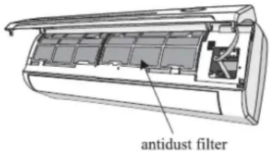
natural_image
Cross-sectional diagram of an air conditioner unit showing internal compartments and ventilation duct (no text or labels)Congratulations on your purchase of this product.
We recommend that you take some time to carefully read this Instructions / Installation Manual in order to make good use of it.
Carefully read all safety instructions before using the device and keep this Instruction / Installation Manual for future reference.
This equipment must be installed by an appropriately qualified professional.
Improper installation or installation that does not meet the manufacturer's specifications will exclude the equipment from the warranty.
1. SAFETY INSTRUCTIONS

PLEASE READ ALL INSTRUCTIONS CAREFULLY BEFORE USING THE PRODUCT.

THIS APPLIANCE HAS BEEN DESIGNED FOR HOME USE ONLY.
- Contact an authorized service technician for installation, repair, and maintenance
of the unit.
- If necessary, replacement of the power cord should only be carried out by qualified personnel.
- The installation will be carried out in compliance with national regulations on electrical connections. Installation will be the sole responsibility of authorized personnel.
- In order to avoid injury to the user and other persons as well as material damage, the following instructions must be observed. Incorrect use of the unit by not reading the instructions may cause physical and material damage.
- During installation of indoor and outdoor units, access to work area must be prohibited for children.
- Make sure the base of the outdoor unit is properly secured.
- Verify that air cannot enter in the refrigerant system and verify that there is no refrigerant when the air conditioner is moved.
- Make sure that the mains voltage corresponds to that required by the device.
- Keep the power switch or plug clean. Insert the power plug correctly.
- Check that the plug is adequate.
- Do not install the device within 50 cm of flammable substances (alcohol, etc.) or pressurized containers, e.g. aerosol cans.
- If the appliance is used in areas where ventilation is not possible, precautions should be taken to prevent gas leaks, as this could cause serious problems.
- Packaging materials are recyclable and must be disposed of in the containers provided for this purpose. Take the end-of-life air conditioner to a special waste collection center for disposal.
- This appliance can be used by children over 8 years of age and people with reduced physical, sensory or mental abilities or lack of experience and knowledge if they have been given supervision or instructions on the use of the application in a safe manner and understand the hazards involved. Children should not play with the device. User cleaning and maintenance should not be performed by unsupervised children.
• Children should be supervised so that they do not play with the appliance.
- Cleaning and maintenance must be carried out by specialised technical personnel. In any case, disconnect the appliance from the mains before carrying out any cleaning or maintenance.
- Do not disconnect the plug to turn off the unit during operation, as this may cause irreversible damage to the unit.
- Always use the appliance with the air filter mounted. Use of the conditioner without an air filter may cause excessive accumulation of dust or debris which will affect the performance of the appliance.
- Never stay directly exposed to cold airflow for long periods of time. Direct and prolonged exposure to cold air can be dangerous to your health. Special care should be taken in rooms where there are children, the elderly or the sick.
- The direction of air flow must be correctly adjusted. The fins must face downwards in heating mode and upwards in cooling mode.
- If the appliance emits smoke or has a burning odor, immediately shut off the power supply and contact after sales service.
- Make sure the appliance is disconnected from the power supply when it is idle for an extended period of time and before performing any cleaning or maintenance.
- Be careful when unpacking the unit. Sharp borders could cause injury.
- Do not bend, pull or compress the power cord as this could damage it. Electric shock or fire is probably due to a damaged power cord. If the cable is damaged, call the service technician for the device.
- Do not use extensions or group modules.
- Do not touch the appliance with bare feet or wet or damp parts of the body.
- Do not obstruct the air inlet or outlet on any of the units, both indoors and outdoors. Obstruction of these openings causes a reduction in the operating efficiency of the conditioner with possible failures or consequential damage.
- Do not install the appliance in environments where air may contain gas, oil, or sulfur, or near heat sources.
- Do not drink drained water from the air conditioner.
2. MAIN PARTS AND FEATURES INDOOR UNIT
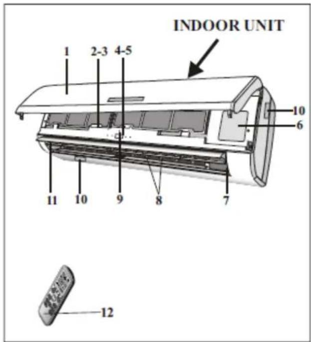
1 Front panel
2 Air filter
3 Optional filter
4 LED display
5 Signal receiver
6 Terminal protective cover
7 Ion generator (optional)
8 Deflectors
9 Emergency knob
10 Indoor unit label
11 Airflow inlets
12 Remote control
OUTDOOR UNIT
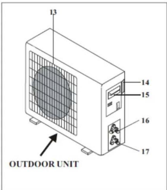
13 Air outlet grille
14 Outdoor unit label
15 Terminal protective cover
16 Gas valve
17 Liquid valve
Note: Images are for guidance only and may vary based on the model purchased.
| Model UAA3000R32-19 | |
| DC inverter motor | |
| Energy class A++ | |
| With heat pump | |
| With remote control | |
| With timer | |
| Gas R32 | |
| Maximum power: 3000 frigorías | |
| Ideal for rooms between 14 and 22 m2 | |
| Indoor unit | Cooling/heating capacity: 1000-3770 / 1000-3810 W |
| Consumption cooling / heating: 290-1320 / 290-1400W | |
| SEER/SCOP: 6.5W /W 4W/W | |
| Air flow rate: 550 m3/h | |
| Noise level: 32 to 50 DB | |
| Dimensions: 77,7 x 20,5 x 25 cm | |
| Outdoor unit | Compressor Type: Rotary |
| Gas preload R32 from 3 m: 15gr/m | |
| Liquid/gas refrigeration connections: 1/4" / 3/8" | |
| Noise level: 60 DB | |
| Dimensions: 71,5 x 49,2 x 24 cm |
| Model UAA4500R32-19 | |
| DC inverter motor | |
| Energy class A++ | |
| With heat pump | |
| With remote control | |
| With timer | |
| Gas R32 | |
| Maximum power: 4500 frigorías | |
| Ideal for stays between 20 to 35 m2 | |
| Indoor unit | Heating/Cooling Capacity: 1250-5920 / 1350-6280W |
| Consumption cooling / heating: 2330-2250 / 340-2350W | |
| SEER/SCOP: 6,3W /W 4W/W | |
| Air flow rate: 800 m3/h | |
| Noise level: 37 to 53 dB | |
| Dimensions: 91 x 29,2 x 20,5 cm | |
| Outdoor unit | Compressor Type: Rotary |
| Gas preload R32 from 3 m: 15gr/m | |
| Liquid/gas refrigeration connections: 1/4" / 3/8" | |
| Noise level: 65 DB | |
| Dimensions: 78 x60,2 x 34,7 cm |
| Model UAA6000R32-19 | |
| DC inverter motor | |
| Energy class A++ | |
| With heat pump | |
| With remote control | |
| With timer | |
| Gas R32 | |
| Maximum power: 6000 frigorías | |
| Ideal for stays between 27 to 45 m2 | |
| Indoor unit | Heating/Cooling Capacity: 1830 - 7810 / 1850 -7930W |
| Consumption cooling / heating: 410-2800 / 420-3000W | |
| SEER/SCOP: 6.5W /W 4.1W/W | |
| Air flow rate: 980 m3/h | |
| Noise level: 40 to 54 dB | |
| Dimensions: 101 x 31,5 x 22 cm | |
| Outdoor unit | Compressor Type: Rotary |
| Gas preload R32 from 3 m: 20gr/m | |
| Liquid/gas refrigerant connections: 1/4" / 1/2" | |
| Noise level: 67 DB | |
| Dimensions: 84,5 x 69,3 x 336 cm |
3. DISPLAY AND REMOTE CONTROL DISPLAY
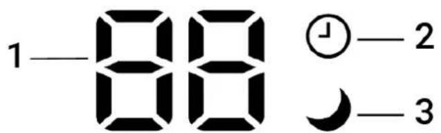
| SYMBOL | FUNCTION | MEANING |
| ON/OFF | This symbol appears when the unit is turned on. | |
 | SLEEP | This symbol appears when night mode is activated. |
 | TEMPERATURE /ERROR DISPLAY | The unit displays the selected temperature or the error code when the error occurs. |
 | TIMER | This symbol illuminates when the timer is activated. |
 | RUN | This symbol appears when the unit is turned on and disappears when the unit is turned off. |
REMOTE CONTROL
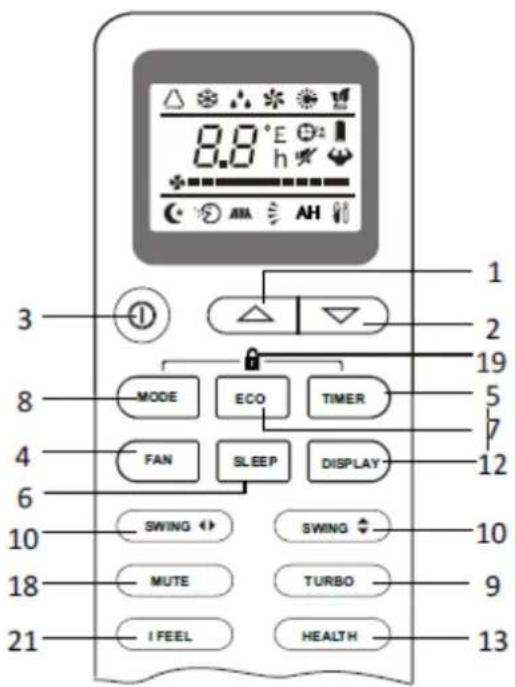
| NO. | FUNCTION | MEANING |
| 1 |  (TEMP UP) (TEMP UP) | Press to increase temperature / set time |
| 2 | [×K36] (TEMP DN) | Press to lower temperature / set time |
| 3 |  ON/OFF ON/OFF | Press to turn the device on/off |
| 4 | FAN | Press to set the fan speed to auto/low/medium/high. |
| 5 | TIMER | Press to set the timer |
| 6 | SLEEP | Press to activate night mode |
| 7 | ECO | Press this button to activate or deactivate the ECO mode. |
| 8 | MODE | Press this button to select the operating mode |
| 9 | SUPER / TURBO | Press this button to activate/deactivate the turbo function, which will allow the unit to reach the temperature in the shortest possible time. |
| 10 | SWING X / SWING ↑L-R | To activate or deactivate the horizontal movement of the fins |
SWING / SWING Y / 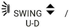 | To activate or deactivate the vertical movement of the fins | |
| 11 | CLOCK | Press this button to set the time on the appliance. By pressing this button the time flash and you can set the correct time using the arrows “▲” or “▼”. Pressing it button again, time will stop flashing and it will be set (if applicable). |
| 12 | DISPLAY | To turn the display on/off (If applicable) |
| 13 | HEALTHY / HEALTH / PLASMA | To turn the HEALTH function on/off. With this button you will control the generation of ions (Optional Functionality) |
| 14 | 3D | When you press "3D", the horizontal and vertical palettes will move together at the same time. (Optional) |
| 15 | RESET | To reset the remote control (Optional) |
| 16 | ANTI-MILDEW / MILDEW | To set the Anti-mould function (Optional) |
| 17 | ANTI-MOSQUITO | To activate the ANTI-MOSQUITO function. (Optional) |
| 18 | Mute | To activate the mute function (Optional) |
| 19 | (MODE+TIMER) | Press both buttons to set the child safety lock (Optional) |
| 20 | AH | To activate the 8th heating function (Optional) |
| 21 | I FEEL | To switch the "I FEEL" function on/off. The air conditioning will regulate the temperature of the room based on theambient temperature of the indoor unit.This function will end automatically after 2 hours of operation (Optional) |
| 22 | I SET | To turn on/off the I SET function, detailed in this manual |
| 23 | CLEAN | Turn on/off the self-cleaning function described later in this manual.Note: It is suggested not to use this function constantly. Its use is recommended once every 3 months. |
Remote controller DISPLAY
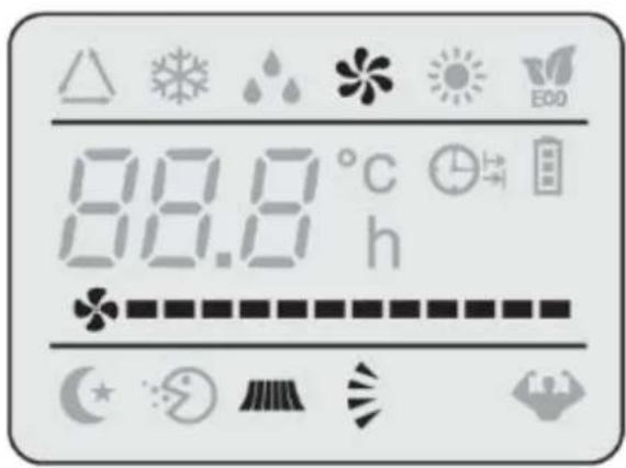
Meaning of symbols on the liquid crystal display.
| No | Symbols | Meaning |
| 1 |  | FEEL mode indicator |
| 2 |  | COOLING indicator |
| 3 |  | DEHUMIDIFYING indicator |
| 4 |  | FAN ONY OPERALTION indicator |
| 5 |  | HEATING indicator |
| 6 |  | SIGNAL RECEPTION indicator |
| 7 |  | TIMER OFF indicator |
| 8 |  | TIMER ON indicator |
| 9 |  | AUTO FAN indicator |
| 10 |  | LOW FAN SPEED indicator |
| 11 |  | MIDDLE FAN SPEED indicator |
| 12 |  | HIGH FAN SPEED indicator |
| 13 | [C722] | SLEEP indicator |
| 14 |  | FLAP SWING indicator |
| 15 |  | SUPER indicator |
| 16 | [SY8] | HEALTHY indicator |
| 17 |  | ECO indicator |
| 18 | [CHD8] | BATTERY indicator |
| 19 | [TT40] | CLOCK indicator |
| 20 | [SRSA] | Mute indicator |
Note: Orientative images. The remote control may vary depending on the model purchased.
Remote control battery replacement
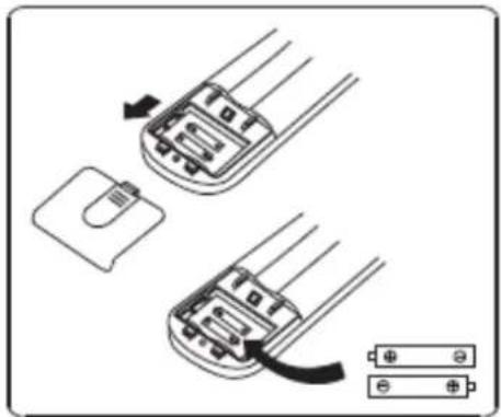
Remove the battery cover from the back of the remote control by sliding it in the direction of the arrow. Install the batteries according to the direction (+ and -) shown on the remote control and gently slide the cover back in.
natural_image
Diagram showing two electronic components with a switch and battery, no text or symbols present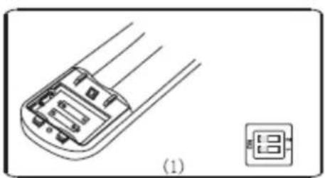
natural_image
Technical line drawing of a battery terminal with three leads and a small 13-pin display (no text or symbols)
Use 2 LRO 3 AAA (1.5V) batteries. Do not use rechargeable batteries. Replace old batteries with new ones of the same type when the remote control display is not legible.

Do not dispose of batteries in the general waste container. Batteries should be recycled in the appropriate container.
After adjusting the function, the batteries must be removed and the procedure described above repeated.
When you first insert the batteries into the remote control or if you replace them, you need to program the remote control in cool mode only or cool and heat.
When you insert the batteries, the 🔗 hot and ✦ cool symbols will flash on the remote control display. By pressing any button when the ✦ cool icon appears, the AC will be set to cool mode. Conversely, by pressing any button on the remote when the 🔗 heat symbol appears on the display, the remote control will be set to cold and heat mode.
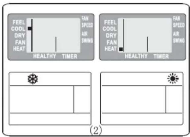

If you set the remote control to cool mode, it will not be possible to use the device in heat mode. To change the operating mode you must remove the series and repeat the process described above by selecting the cold and heat e.
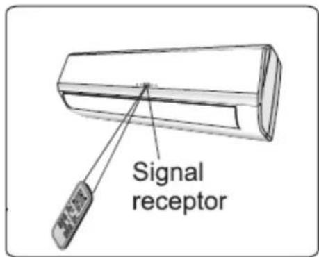
- Point the remote control toward the indoor unit.
- Verify that there are no objects between the remote control and the indoor unit's receiving signal.
-
Never leave the remote control exposed to the sun's rays.
-
Keep the remote control at least 1 meter away from the TV and other electrical appliances.
4. OPERATING THE APPLIANCE
AIR FLOW CONTROL
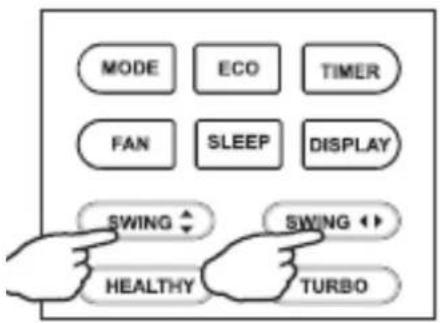
The air outlet flow is evenly distributed throughout the room. It is possible to redirect the flow of air conditioning through the SWING or SWING (SWING) button up or down until the optimum position is found.
With the SWING ◀ SWING button the air can be alternatively directed from left to right. Please check if your model has such functionality.
The following use of the fins is recommended to ensure optimum performance of the device:
• In cooling mode, orient fins horizontally;
• In heating mode, orient fins downward as
hot air tends to rise.

Never move the fins manually. Doing so could damage the device.

Never put fingers, sticks or other objects between the fins or vents of the appliance. Failure to do so could result in injury or damage.
COOL MODE
The cold function allows the room air to cool while reducing air humidity.
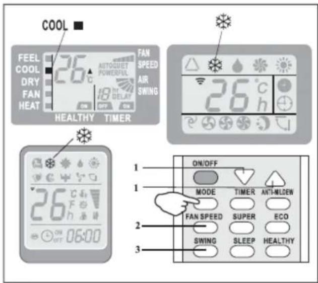
To activate the COOL function, press the MODE button until the ⚙COOL function symbol appears on the screen.
Adjust the temperature using the up and down arrows.
To optimize the operation of the unit, adjust the temperature (1), the speed (2) and the direction of the air flow (3) by pressing the indicated button.
HEAT MODE

The cold function allows the air in the room to warm up.
To activate the HEAT function, press the MODE button until the ⚙️ HEAT function symbol appears on the screen.
Adjust the temperature using the up and down arrows.
To optimize the operation of the unit, adjust the temperature (1), the speed (2) and the direction of the air flow (3) by pressing the indicated button.
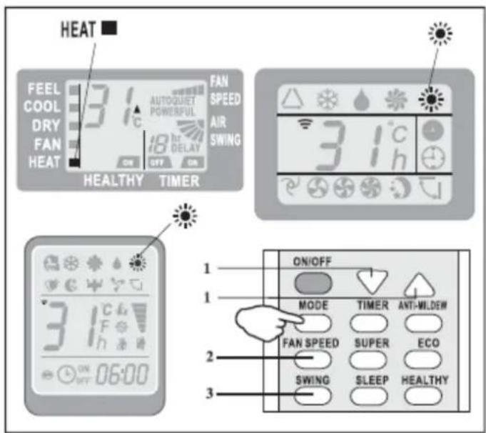
- If the appliance is equipped with a heat pump, it may take a few seconds to switch on the appliance in order to guarantee an immediate output of hot air.
- During the HEAT mode, the appliance can automatically activate a defrost cycle, essential to clean the frost in the condenser and operate properly. This procedure usually takes 2 to 10 minutes and the indoor unit will stop. The HEAT mode will start automatically after defrosting.
TIMER ⏻
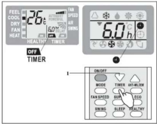
The timer function is used to set the automatic switch-off time of the appliance.
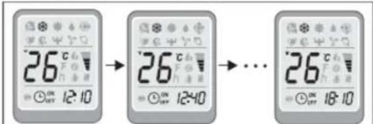
To program the shutdown time, press the TIMER button and adjust working time with the UP and DOWN arrows in 30 minute intervals. Once the desired operating time has been set, press TIMER again.
If you want to cancel the timer, press the TIMER button at any time and the function will stop.
If the unit is switched off, the timer must be reset.
FAN MODE

In this case only the appliance fan will work.
To set the FAN mode, press the MODE button until the ✿ function symbol appears on the screen.
By pressing the FAN button, the fan speed can be set to LOW/MEDIUM/HIGH/AUTO.
The remote control will display the speed used in the previous mode by default.
In FEEL mode, the air conditioning automatically selects the fan speed and operating mode (COOL or HEAT).
DEHUMIDIFIER MODE

This function reduces air humidity in environments where humidity is high, resulting in a more comfortable stay.
To set the DRY or Dehumidifier mode, press
MODE until the function symbol appears on the display.

Indoor display

Indoor display
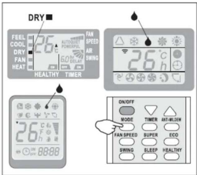
In this mode, the automatic cycles of cooling and ventilation are alternated.
FEEL MODE

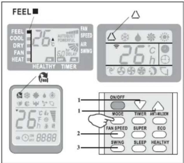
To activate the FEEL operating mode, press the MODE button on the remote control until the corresponding symbol or word FEEL appears on the display.
In FEEL mode the fan speed and temperature are automatically set according to the ambient temperature, which is measured through a temperature sensor built into the indoor unit.
| ROOM TEMPERATURE | OPERATING MODE | AUTOMATIC TEMPERATURE |
| ≤ 20irc | HEAT | 23irc |
| 20TH - 26TH | DEHUMIDIFIER | 18irc |
| ≥ 26irc | COLD | 23irc |
To optimize the operation of the air conditioning, adjust the temperature (only ± 2 C°), speed and direction of air flow by pressing the indicated buttons.
NIGHT MODE
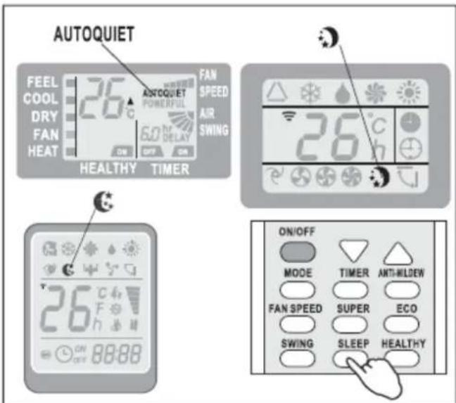
To activate the SLEEP mode, press the SLEEP button on the remote control until the function symbol appears on the screen.
SLEEP mode automatically adjusts the temperature to make the room more comfortable during sleeping hours. In cold or humidifier, the set temperature will

Indoor display
automatically increase by 1°C every 60 minutes, up to a maximum of 2°C.
In heat mode, the set temperature is gradually reduced by 2irc C during the first 2 hours of operation.
After 10 hours of operation in NIGHT mode, the air conditioning will automatically turn off.
EMERGENCY FUNCTION AND RESTART OF THE APPLIANCE
Reset: In the event of a power failure, the device memorizes the conditions of use before the power failure and, once the device is back in operation, it will start in the same mode, temperature and speed as it was previously in operation.
To desactivate the function, proceed as follows:
- Switch off the appliance and disconnect it from the power supply.
- Press the emergency button while switching on the power.
- Press the emergency button for 10 seconds until you hear a sound. The restart function has been deactivated.
- To activate the function again, repeat this procedure until you hear the sound 3 times.
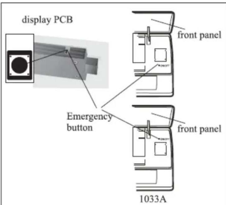
The emergency button in some models could be on the right part of the unit under the front panel.
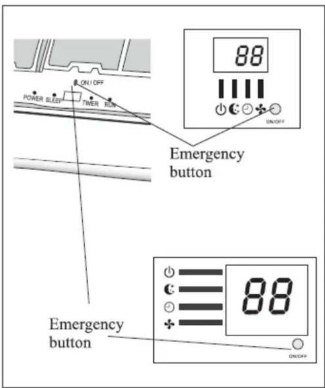
EMERGENCY: If the remote control fails, open the front cover of the indoor unit and look for the emergency button.
- Press the emergency button once (until you hear a sound) and the device will be forced to work in COLD mode.
-
Press the emergency button 2 times for 3 seconds (until you hear 2 sounds) and the device will be forced to work in HEAT mode.
-
To turn the power off, press the emergency button again (you will hear a long beep).
-
After 30 minutes of forced operation after using the emergency button, the unit will automatically run at 23irc in cold mode with fan in automatic speed.
TEMPERATURE SETTING
The air conditioning is programmed to be used based on the temperatures listed below. If temperatures other than those listed above are used, certain protective measures may be activated to prevent irreparable damage to the device.
| TEMPERATURE / MODE | COOL MODE | HEAT MODE | DRY MODE. |
| Room temp. | 17 Co to 32 Co | 0 Co to 30 Co | 10 Co to 32 Co |
| Outdoor temp. | 0 Co to 53 Co -15 Co to 53 Co (For some models only) | -15 Co to 30 Co | 0 Co to 50 Co |

The unit does not operate immediately if it is turned on after being turned off or after changing the operating mode. This is a common form of self-protection you need to wait about 3 minutes to work again.

Information based on factory test performed *
* Max. motor speed of indoor unit and maximum opening angle of fins
5. INSTALLATION
PRECAUTIONS:
- The appliance must be installed by authorized professional personnel. Otherwise the appliance may be automatically without any warranty from the manufacturer.
- The gas in the appliance may only be charged by authorized professional personnel. This task is dangerous and can cause damage if not performed properly.
- A test to check for possible gas leaks should be performed once the equipment has been installed.
- The requirements regarding the type and quantity of gas in each appliance can be found in this manual.
Where LFL is the gas limit in kg / m3. For the R32 LFL is 0.306 kg / m3 -
For appliances with loads between m1 and m2 the maximum load in a room must be according to the following formula: mmax = 2.5 × (LFL)(5/4) × hirc × A1/2
Where the minimum area Amin to install the appliance with the gas load M (kg) should be as follows Amin = M / 2.5 × ((LFL)(5/4) × h0))2
Mmax is ka maximum load in the room, per kg
M is the quantity of gas charged in the appliance, in kg
Amin is the minimum area of the room in m2
A is the area of the room in m2
LFL, the gas limit, in Kg/m3
H0 is the installation height of the device
Table GG.1 – Maximum charge (kg)
| Category | LFL(kg/m3) | h0 (m) | Floor area (m2) | ||||||
| 4 | 7 | 10 | 15 | 20 | 30 | 50 | |||
| R290 | 0.038 | 0.6 | 0.05 | 0.07 | 0.08 | 0.1 | 0.11 | 0.14 | 0.18 |
| 1 | 0.08 | 0.11 | 0.13 | 0.16 | 0.19 | 0.2 | 0.3 | ||
| 1.8 | 0.15 | 0.2 | 0.24 | 0.29 | 0.34 | 0.41 | 0.53 | ||
| 2.2 | 0.18 | 0.24 | 0.29 | 0.36 | 0.41 | 0.51 | 0.65 | ||
| R32 | 0.306 | 0.6 | 0.68 | 0.9 | 1.08 | 1.32 | 1.53 | 1.87 | 2.41 |
| 1 | 1.14 | 1.51 | 1.8 | 2.2 | 2.54 | 3.12 | 4.02 | ||
| 1.8 | 2.05 | 2.71 | 3.24 | 3.97 | 4.58 | 5.61 | 7.254 | ||
| 2.2 | 2.5 | 3.31 | 3.96 | 4.85 | 5.6 | 6.86 | 8.85 | ||
Table GG.2 - Minimum room area (2)
| Category | LFL(kg/m3) | h0 (m) | Charge amount (M) (kg)Minimum room area (m2) | ||||||
| R290 | 0.038 | 0.152kg | 0.228 kg | 0.304 kg | 0.456 kg | 0.608 kg | 0.76 kg | 0.988 kg | |
| 0.6 | 82 | 146 | 328 | 584 | 912 | 1514 | |||
| 1 | 30 | 53 | 118 | 210 | 328 | 555 | |||
| 1.8 | 9 | 16 | 36 | 65 | 101 | 171 | |||
| 2.2 | 6 | 11 | 24 | 43 | 68 | 115 | |||
| R32 | 0.306 | 1.224 kg | 1.836 kg | 2.448 kg | 3.672 kg | 4.896 kg | 6.12 kg | 7.956 kg | |
| 0.6 | 29 | 51 | 116 | 206 | 321 | 543 | |||
| 1 | 10 | 19 | 42 | 74 | 116 | 196 | |||
| 1.8 | 3 | 6 | 13 | 23 | 36 | 60 | |||
| 2.2 | 2 | 4 | 9 | 15 | 24 | 40 | |||
Tips for correct installation:
- The place of installation should be a well ventilated room. - Installation place must be free of open fuel and any source of heat greater than 548irc C that easily emits gases and fumes.
- It is necessary to choose the place where the installation or maintenance is convenient and where the air inlets and outlets are perfectly uncovered and not obstructed.
- If the indoor unit suffers a refrigerant leak during installation, it is necessary to immediately shut off the outdoor unit valve and empty the staff room for at least 15 minutes. If the product is damaged, before installation please repack the product and contact the supplier.
- It is necessary to avoid placing the indoor unit directly above other electrical appliances, plugs, furniture, beds, sofas or other furniture.
INDOOR UNIT INSTALLATION
• Install the indoor unit on a strong wall that is not subject to vibration.
- The ports of entry and exit must not be obstructed: the air must be able to run in the room.
- Do not install the unit near a source of heat, steam, or flammable gas.
• Install the unit near an electrical outlet.
- Do not install the unit in places exposed to direct sunlight.
- Select a location where condensed water can be easily drained and easily connected to the outdoor unit.
- Regularly check the operation of the machine and reserve the necessary space for installation, as shown in the picture.
- Select a location where the filter can be easily removed.
- Before starting the installation, decide the position of the indoor and outdoor units, taking into account the minimum space reserved around the units.
- Do not install your air conditioner in a damp room such as a bathroom, laundry room etc.
- The indoor unit must be installed at a minimum height of 250 cm.
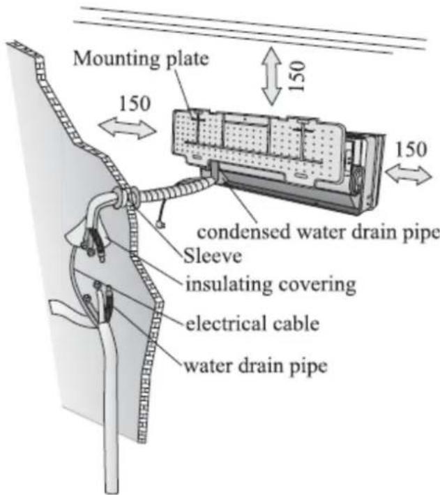
To install the indoor unit, proceed as follows.
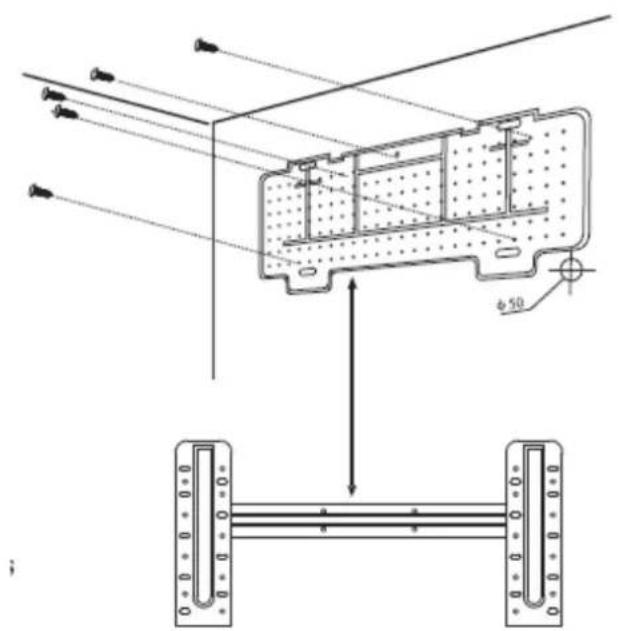
Mounting Panel Installation
• Always mount the rear panel horizontally and vertically
- Drill a hole 32 mm deep to fix the panel.
- Insert the plastic anchors into the hole;
- Fasten the rear panel to the wall with the supplied threaded screws.
- Make sure the rear panel is secured enough to support the weight of the applato.
Note: the shape of the mounting panel may differ from the image in the manual but the installation method will be similar in any case.
Pipe Installation
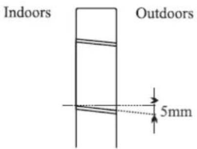
- Drill the pipe hole in the wall with a slight tilt to the outside.
- Insert the pipe sleeve into the orifice to prevent damage to the connecting pipe and turning when passing through the hole.
Note: Keep the pipe in the direction of the hole to avoid gas leaks.
Indoor Unit Connections
- Open the front panel.
- Remove the cover as shown in the picture (removing a screw).
- For electrical connections, refer to the circuit diagram on the right side of the unit below the front panel.
- Connect the wires to the screw terminals following the numbering. Use the proper cable size for power input (see nameplate on unit) and in accordance with all applicable national safety codes.

The cable connecting the outdoor and indoor units must be suitable for outdoor use.

The plug must be accessible once the appliance has been installed.

Efficient grounding must be ensured.

If the power cord is damaged, it must be replaced by an authorized service center.
Note: Optionally, the cables can be connected to the main PCB of the indoor unit depending on the model purchased.
Gas pipe connection
The pipe can be installed in 3 different directions, as shown in the drawings below. When the pipe is installed in position 1 or 3, make a cut with cutex.
Install the pipe in the direction of the hole in the wall and tape the copper pipes, drain pipe and electrical wires together so that water can flow freely.
Do not remove the pipe cap until it is connected, to prevent dirt or moisture from entering the pipe.
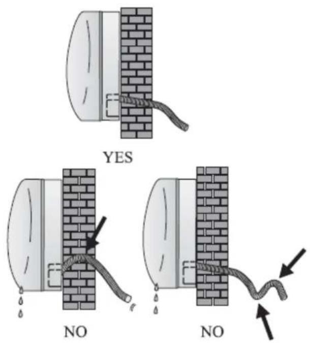
Do not bend the pipe too far and try to extend or stretch it as shown in the pictures.
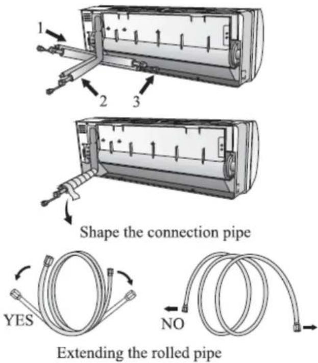
Connecting the indoor unit
- Remove the cap that covers the piping from the indoor unit.
- Insert the nut, as shown in the picture.
- Tighten the connections using a wrench tightening in betting directions
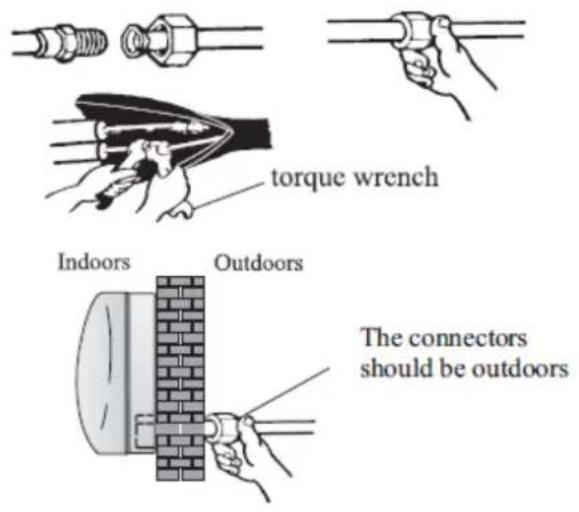
Water drainage
The drainage of the condensed water is fundamental for a correct installation.
- Place the drain hose under the pipe.
- The drain pipe must be inclined to allow water to drain.
- Do not bend the drain pipe or place the end of the pipe submerged in water.
- If the pipe is installed on the right, the pipes, electrical cables and drain pipe must be installed behind the unit with a connecting pipe.
- Insert the connection tube into the corresponding slot.
- Press for unit the tube to the base.
After connecting the piping according to the instructions, install the connecting cables. Now install the drain pipe. After connection, cover the pipe, cables and drain pipe with insulating material.
- Position pipes, cables and drain hose securely.
- Cover pipe joints with insulating material and secure with tape.
• Pass the attached pipe, cables, and drain pipe through the hole in the wall and mount the
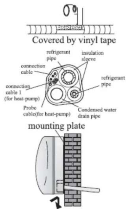
indoor unit securely to the top of the mounting panel.
- Press and push the bottom of the indoor unit against the mounting panel. OUTDOOR UNIT INSTALLATION
- Do not install the outdoor unit near sources of heat, steam, or flammable gas.
- Do not install the unit in windy or dusty locations.
- Do not install the unit where people pass often. Select a location where the air discharge and operating sound will not disturb neighbors.
- Avoid installing the unit where it will be exposed to direct sunlight (otherwise use protection, if necessary).
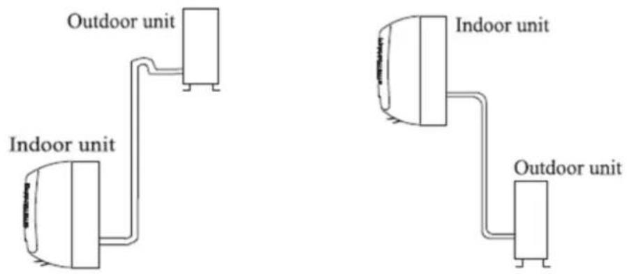
- Reserve the spaces as shown in the image to allow air to circulate freely.
• Install the outdoor unit in a safe and solid location. - If the outdoor unit is subject to vibration, place rubber gaskets on the feet of the unit. It is recommended to use more screws than usual to avoid vibrations.
- The following procedure should be observed before connecting pipes and connecting cables: decide which is the best position on the wall and leave enough space for easy maintenance.
• Fix the bracket to the wall using anchor screws. - The unit must be installed in accordance with national standards and regulations.
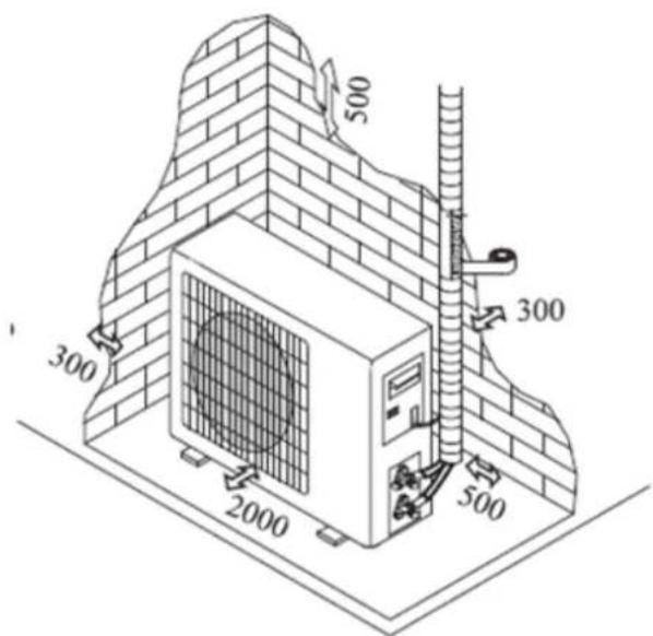
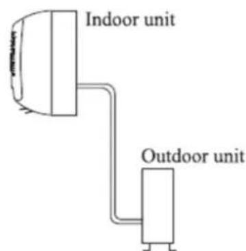
Installation diagram:
flowchart
graph TD
    A["Indoor unit"] --> B["Outdoor unit"]
    C["Indoor unit"] --> D["Outdoor unit"]
    style A fill:#f9f,stroke:#333
    style C fill:#f9f,stroke:#333
    style B fill:#ccf,stroke:#333
    style D fill:#ccf,stroke:#333
Outdoor unit: Outdoor unit
Indoor unit: Indoor unit
Drainage of water in the outdoor unit
Condensed water and ice formed in the outdoor unit during use in heat mode can be drained through the drain pipe.
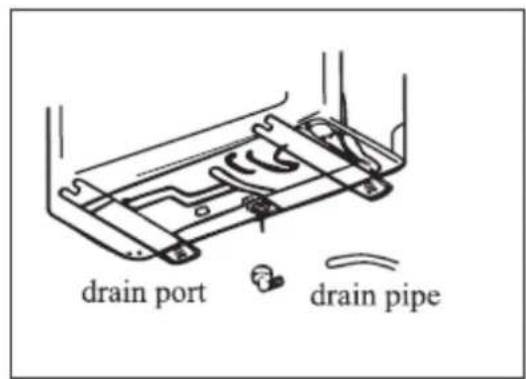
- Attach the drain tube to the 25 mm hole in the outdoor unit as shown.
- Connect drain port and drain tube.
• Make sure that the water is drained in a suitable place.
Electrical connections
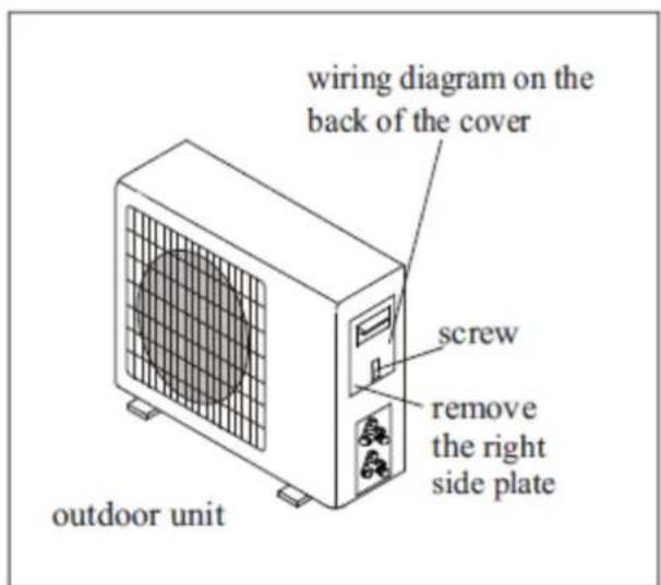
- Remove the handle on the right side of the outdoor unit.
- Connect the power connection cable to the connection terminal. The wiring must match that of the indoor unit.
- Secure the electrical connection cable with wire. Make sure that the cable is securely fastened.
• Efficient grounding must be ensured. - Replace the gripper.
Pipe connection
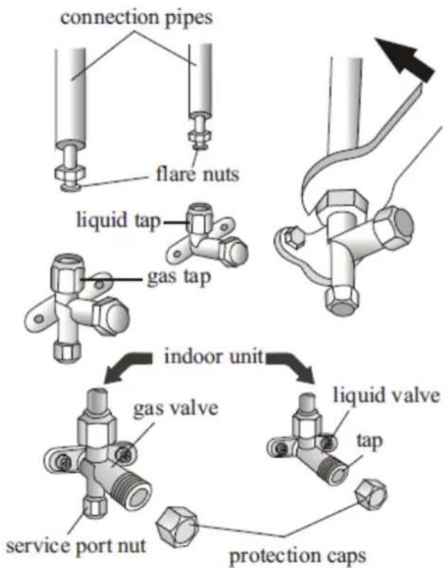
Screw the flare nuts to the outdoor unit using the same procedures described for the indoor unit.
To avoid leaks, pay attention to the following points:
- Tighten the nuts with two wrenches. Be careful not to damage the pipes.
- If not tightened enough, it will probably cause gas leaks. Over-tightening may also cause gas leaks if pipes are damaged.
- The safest system is to tighten the connection using a spanner and a torque wrench.
Pressure check
The minimum pressure for R32 gas appliances is 0.8-1.2 Mpa and the maximum pressure is 3.2-3.7 Mpa. The cooling system will be abnormal when functions outside the mentioned ranges.
Air purge
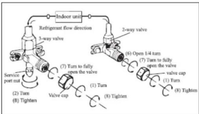
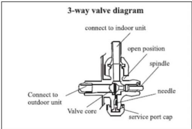
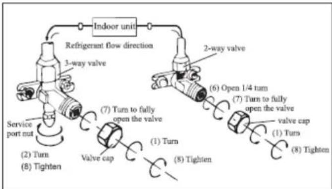
Air and moisture inside the refrigerant circuit can cause the compressor to malfunction. After you have connected the indoor and outdoor units, purge the air and moisture from the refrigerant circuit using a vacuum pump.
flowchart
graph TD
    A["Indoor unit"] --> B["Refrigerant flow direction"]
    B --> C["3-way valve"]
    C --> D["Service port nut"]
    D --> E["(2) Turn"]
    E --> F["(8) Tighten"]
    F --> G["Valve cap"]
    G --> H["(7) Turn to fully open the valve"]
    H --> I["(1) Turn"]
    I --> J["(8) Tighten"]
    J --> K["Valve cap"]
    K --> L["(6) Open 1/4 turn"]
    L --> M["(7) Turn to fully open the valve"]
    M --> N["valve cap"]
    N --> O["(1) Turn"]
    O --> P["(8) Tighten"]
Please follow the following notes to bleed the air from the device:
• Unscrew and remove valve caps 2 and 3.
- Unscrew and remove the port cover.
- Connect the vacuum pump hose to the port.
- Run the vacuum pump for 10 to 15 minutes until an absolute vacuum of 10 mm Hg is reached.
- With the vacuum pump still running, close the pump valve. Then switch off the vacuum pump.
- Open the 2-way valve 1/4 turn and then close it after 10 seconds. Check all joints using liquid soap or an electronic leakage device.
- Turn the body of the 2-way and 3-way valves.Disconnect the hose from the vacuum pump.
- Replace and tighten all valve caps.
Functionality test
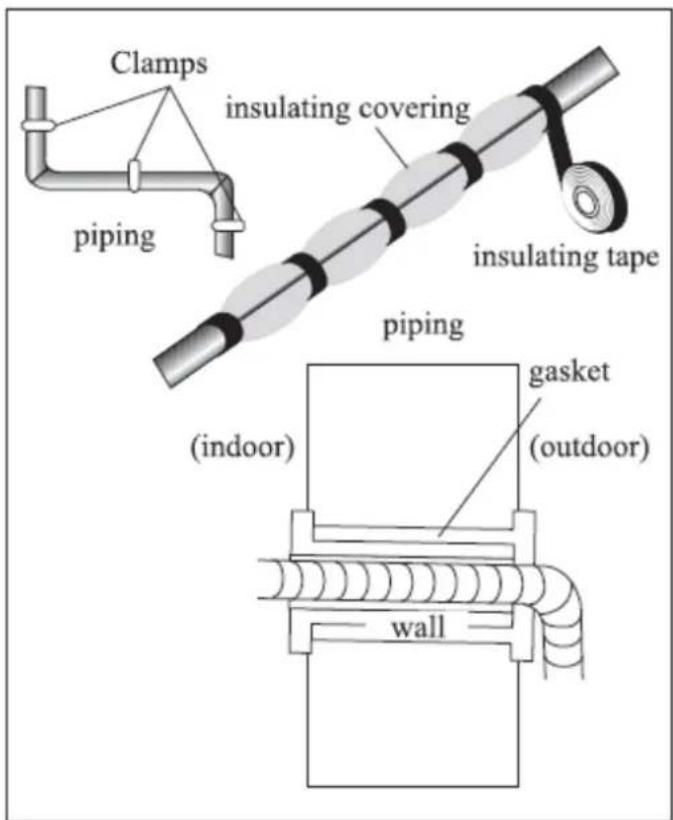
- Use insulation around the joints of the indoor unit and secure with insulation.
- Attach the excess part of the signal cable to the pipe or to the outdoor unit.
- Attach the pipe to the wall (after coating with insulating tape).
- Seal the hole in the wall through which the pipe passes so that air or water cannot fill.
Indoor unit test
- Do the ON/OFF and FAN functions work normally?
- Does the MODE work normally?
- Does the set point and TIMER work correctly?
- Does each lamp light up normally?
- Does the lid normally work for the direction of air flow?
• Is the condensed water drained regularly?
Outdoor unit test
• Is there any abnormal noise or vibration during use?
• Could noise, airflow or condensation drainage disturb neighbours?
• Is there a refrigerant leak?
Information for the installer
| MODEL | 9k/12k | 18k/24k |
| Tube length with standard load | 5 m | 5 m |
| Max. distance between indoor and outdoor unit | 25 m | 25 m |
| Additional Gas Charge (Starts at 5m) | 15 g/m | 25 g/m |
| Max. level difference between indoor and outdoor unit | 10 m | 10 m |
| Type of gas | R32 | R32 |
Tightening screws
| Pipe | Tightening screw (N x m) | Corresponding pressure | Tightening bolt ( N x m) | |
| "1⁄4" (ø 6) | 15-20 | Wrist strength | Port Nut | 7-9 |
| 3/8" (ø 9.52) | 31-35 | Arm strength | Protective covers | 25-30 |
| "1⁄2" (ø 12) | 35-45 | Arm strength | ||
| 5/8" (ø 15.88) | 75-80 | Arm strength |
Wiring diagram
For different models, the wiring diagram may be different. Refer to the wiring diagrams glued to the unit on the inside and outside of the unit, respectively.
In the indoor unit, the wiring diagram is glued under the front panel;
On the outdoor unit, the wiring diagram is glued to the back of the outer handle cover.

Wiring Specifications
| MODEL capacity (Btu/h) | 5k | 7k | 9k | 12k | 15/18k | 22/24k | 28/30k/36k | |
| sectional area | ||||||||
| Power supply cable | N | 1.0mm2 AWG18 | 1.0mm2 AWG18 | 1.0mm2 AWG18 | 1.0mm2(1.5mm2) AWG18(AWG16) | 1.5mm2 AWG16 | 2.5mm2 AWG14H05RN-F | 4.0mm2 AWG12 |
| L | 1.0mm2 AWG18 | 1.0mm2 AWG18 | 1.0mm2 AWG18 | 1.0mm2(1.5mm2) AWG18(AWG16) | 1.5mm2 AWG16 | 2.5mm2 AWG14H05RN-F | 4.0mm2 AWG12 | |
| E | 1.0mm2 AWG18 | 1.0mm2 AWG18 | 1.0mm2 AWG18 | 1.0mm2(1.5mm2) AWG18(AWG16) | 1.5mm2 AWG16 | 2.5mm2 AWG14H05RN-F | 4.0mm2 AWG12 | |
| Connection supply cable | N | 1.0mm2 | 1.0mm2 | 1.0mm2 | 1.0mm2(1.5mm2) | 1.5mm2 | 0.75mm2 | 0.75mm2 |
| L | 1.0mm2 | 1.0mm2 | 1.0mm2 | 1.0mm2(1.5mm2) | 1.5mm2 | 0.75mm2 | 0.75mm2 | |
| 1 | 1.0mm2 | 1.0mm2 | 1.0mm2 | 1.0mm2(1.5mm2) | 1.5mm2 | 0.75mm2 | 0.75mm2 | |
| 2 | 0.75mm2 | 0.75mm2 | 0.75mm2 | 0.75mm2 | 0.75mm2 | 0.75mm2 | 0.75mm2 | |
| 3 | 0.75mm2 | 0.75mm2 | 0.75mm2 | 0.75mm2 | 0.75mm2 | 0.75mm2 | 0.75mm2 | |
| 0.75mm2 | 0.75mm2 | 0.75mm2 | 0.75mm2 | 0.75mm2 | 0.75mm2 | 0.75mm2 | ||
| INVERTER TYPEMODEL capacity (Btu/h) | 9k | 12k | 18/22k | 24k | |||||
| sectional area | |||||||||
| Power supply cable | N | 1.0mm2 (1.5mm2) AWG18(AWG16) | 1.0mm2 (1.5mm2) AWG18(AWG16) | 1.5mm2 AWG16 | 2.5mm2 AWG14 | ||||
| L | 1.0mm2 (1.5mm2) AWG18(AWG16) | 1.0mm2 (1.5mm2) AWG18(AWG16) | 1.5mm2 AWG16 | 2.5mm2 AWG14 | |||||
| E | 1.0mm2 (1.5mm2) AWG18(AWG16) | 1.0mm2 (1.5mm2) AWG18(AWG16) | 1.5mm2 AWG16 | 2.5mm2 AWG14 | 1.0mm2 (1.5mm2) AWG18(AWG16) | ||||
| Connection supply cable | N | 1.0mm2 (1.5mm2) | 1.0mm2 (1.5mm2) | 1.5mm2 | 0.75mm2 | ||||
| L | 1.0mm2 (1.5mm2) | 1.0mm2 (1.5mm2) | 1.5mm2 | 0.75mm2 | |||||
| I | 1.0mm2 (1.5mm2) | 1.0mm2 (1.5mm2) | 1.5mm2 | 0.75mm2 | |||||
| 1.0mm2 (1.5mm2) | 1.0mm2 (1.5mm2) | 1.5mm2 | 0.75mm2 | ||||||
220V 7K, 9K, 12K, 15K, 16K, 18K, 22K, 24K, 30k indoor unit fuse is 50T, 3.15 A
110V 7K, 9K, 12K, indoor unit fuse is 50T, 3.15 A
115V 7K, 9K, 12K, outdoor unit fuse is 61T, 15 A
250V 18K,22K, 24K outdoor unit fuse is 65TS, 25A
6. MAINTENANCE
Regular maintenance of this appliance is essential.
Before carrying out any maintenance, disconnect the unit from the power supply.
Indoor unit maintenance
Cleaning the filter
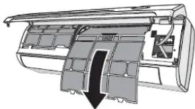
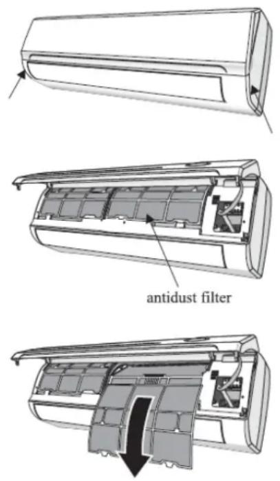
- Open the front panel in the direction of the arrow.
- Holding the front panel up with one hand, remove the air filter with the other hand.
- Clean the filter with water; if the filter is stained with oil, it can be washed with warm water (not exceeding 45°C).
- Leave to dry in a cool, dry place.
- Keeping the front panel raised with one hand, insert the air filter with the other hand and close the panel again.
If the odour filter is installed, it cannot be washed. This filter must be replaced every 6 months.
Outdoor unit maintenance
- Open the front panel of the unit and turn it back on at full power and then unhook it from the hinges for easy cleaning.
- Clean the unit r with a cloth with water (not more than 40 °C) and neutral soap. Never use aggressive solvents or detergents.
- If the outdoor unit is clogged, remove any leaves or debris and blast off dust or water.
End of season maintenance
- Disconnect the appliance from the mains socket.
- Clean and replace filters.
- On a sunny day, allow the conditioner to work with ventilation for a few hours so that the inside of the unit can dry completely.
Replace the batteries
Batteries should be replaced when symptoms show that they have been exhausted:
- No confinement beep is heard from the indoor unit.
- The LCD does not operate.
To do this, remove the back cover and insert the new batteries in accordance with the + and - symbols.

Use only new batteries

WARNING ! Do not dispose of batteries in common waste; dispose of them in special containers at collection points.
7. AFTER-SALES SERVICE
Please take a few minutes to read the following troubleshooting chart before contacting service:
| PROBLEM | POSSIBLE CAUSES |
| The device does not work | The device is not plugged in / Electrical problems |
| Damaged indoor unit / damaged outdoor unit fan | |
| Compressor failure | |
| Fuse protection activated | |
| Voltage higher or lower than required | |
| Timer activated | |
| Damaged electronic boards | |
| Bad odor | Dirty air filter |
| Noise from flowing water | It's common and it's due to the circulation of the refrigerant. |
| Fine smoke from the air outlet | Occurs when the air in the room is very cold, for example in cold or dehumidifier mode |
| A strange noise is heard | This is due to expansion and contraction of the front panel due to temperature variations. It's a common thing |
| Insufficient airflow, neither cold nor heat | Inadequate set temperature |
| The air filter is blocked | |
| Fan speed is at minimum | |
| Lack of gas | |
| Device does not respond to remote control | The remote control is too far from the indoor unit |
| The remote control has no battery | |
| There are obstacles between the signal receiver and the remote control | |
| Display does not work | Activating the LED function |
| Electrical faults | |
| Switch off the device immediately in the following cases: | |
| Electrical boards faults | |
| Fuse failure | |
| Water inside the appliance | |
| Cable overheating | |
| Strong appliance odors | |
ERROR LIST
| Failure Type | LED Code | Digital LED Code |
| Indoor and outdoor communication failure | RUN, TIMER-both winking | E0 |
| Outdoor communication failure | RUN, TIMER-both winking | EC |
| Indoor room temperatura sensor (IRT) | RUN-1time/8s | E1 |
| Indoor coil temperatura sensor (IPT) | RUN-2 times/8s | E2 |
| Outdoor coil temperatura sensor (OPT) | RUN-3 times/8s | E3 |
| System abnormality | RUN-4 times/8s | E4 |
| Model configuration wrong | RUN-5 times/8s | E5 |
| Indoor fan motor fault | RUN-6 times/8s | E6 |
| Outdoor temperatura sensor | RUN-7 times/8s | E7 |
| Exhaust temp. Sensor | RUN-8 times/8s | E8 |
| IPM drive and module fault | RUN-9 times/8s | E9 |
| Outdoor fan motor fault (DC motor) | RUN-10 times/8s | EF |
| Current sensor fault | RUN-11 times/8s | EA |
| Indoor unit EEPROM fault | RUN-12 times/8s | EE |
| Temp. Switch fault (on top of the compressor) | RUN-13 times/8s | EP |
| Voltage sensor fault | RUN-14 times/8s | EU |
This product has a warranty of 2 years from the date of purchase of the product, with the following conditions:
- The guarantee is valid only with the presentation of the purchase invoice of the product.
- Damage caused during transport, negligence or misuse, incorrect assembly or installation, as well as external influences, such as: atmospheric or electrical lightning, flooding, humidity, etc., are not covered by the warranty.
- This warranty ends when it is discovered that they have been subjected to repairs, alterations or interventions by any person not authorized by Universal Blue.
To make use of the warranty go to the center where you purchased this product or contact us in any of the following ways:
- Through the email sat@universalblue.es, attaching the purchase invoice and indicating your contact details and briefly what problem your flask presents.
■ By telephone (0034) 968 893691.
■ At the following address:
UNIVERSAL FOR ENGINEERING INDUSTRIES SPAIN, SL C/ Decenio N1, P.I. Media Legua. Las Torres de Cotillas (Murcia). 30565
8. ENVIRONMENTAL INFORMATION
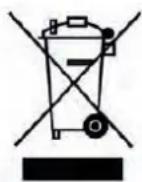
This equipment has been marked in accordance with the European Directive 2012/19/EU concerning the disposal of Waste Electrical and Electronic Equipment (WEEE). The symbol on the device indicates that the product at the end of its useful life should not be treated as normal household waste, but should be taken to separate collection centres for electrical and electronic waste or handed over to the vendor at the time of purchase of a new device. The proper collection of this device helps to avoid possible negative repercussions for the environment or human health. Disposal must comply with local environmental regulations. For more detailed information regarding the treatment, disposal or recycling of this product, please contact your local waste disposal service or the store where you purchased the device. Do not throw the packaging of the device into the trash but select the various materials such as polystyrene, cardboard, plastic bags, etc. in accordance with local waste disposal regulations and current regulations.

The packaging materials of this product are recyclable. You can deposit these materials in a public collection site for recycling.

Download this manual in our web site:


- EMERGENCIA:
- SAFETY INSTRUCTIONS
- MAIN PARTS AND FEATURES INDOOR UNIT
- OUTDOOR UNIT
- DISPLAY AND REMOTE CONTROL DISPLAY
- REMOTE CONTROL
- Remote controller DISPLAY
- Remote control battery replacement
- OPERATING THE APPLIANCE
- AIR FLOW CONTROL
- COOL MODE
- HEAT MODE
- TIMER ⏻
- FAN MODE
- DEHUMIDIFIER MODE
- FEEL MODE
- NIGHT MODE
- EMERGENCY FUNCTION AND RESTART OF THE APPLIANCE
- TEMPERATURE SETTING
- INSTALLATION
- PRECAUTIONS:
- INDOOR UNIT INSTALLATION
- Mounting Panel Installation
- Pipe Installation
- Indoor Unit Connections
- Gas pipe connection
- Connecting the indoor unit
- Water drainage
- - Press and push the bottom of the indoor unit against the mounting panel. OUTDOOR UNIT INSTALLATION
- Drainage of water in the outdoor unit
- Electrical connections
- Pipe connection
- Pressure check
- Air purge
- Functionality test
- Wiring diagram
- MAINTENANCE
- Indoor unit maintenance
- Cleaning the filter
- Outdoor unit maintenance
- End of season maintenance
- Replace the batteries
- Use only new batteries
- AFTER-SALES SERVICE
- ENVIRONMENTAL INFORMATION
Brand : Universal Blue
Model : UAA3000R32-19
Category : Air conditioner