SWP04 - Processor SEADA - Free user manual and instructions
Find the device manual for free SWP04 SEADA in PDF.


| Product Type | Video Wall Controller Processor |
| Model | SWP04 (4U Chassis) |
| Brand | SEADA |
| Chassis Size | 4U Rackmount |
| Dimensions (Approx.) | 482.6 mm (19 in) width x 177.8 mm (4U) height x 450 mm depth |
| Weight (Approx.) | 15 kg |
| Power Supply | Internal AC power supply, 100-240 VAC, 50/60 Hz |
| Power Consumption | Up to 500 W (depending on installed cards) |
| Video Input Cards Supported | DVI, HDMI, VGA, SDI, DisplayPort, HDBaseT, IP, Optical Fiber |
| Video Output Cards Supported | Hybrid slots for output cards |
| Maximum Output Channels | Up to 16 (depending on chassis and card configuration) |
| Control Interface | Ethernet (RJ45) for control PC, RS232 serial, USB for keyboard/mouse |
| Supported Control PC OS | Windows 2000/XP/Vista/7/8/10 |
| Management Software | SWPro Management Software (included on CD) |
| Default IP Address | 192.168.1.65 |
| Bezel Correction | Supported in software configuration |
| Multi Video Wall Support (MVWS) | Yes |
| Compliance | CE, FCC (typical for industrial controllers) |
| Operating Temperature | 0°C to 40°C (typical) |
| Storage Temperature | -20°C to 60°C (typical) |
| Relative Humidity | 10% to 90% non-condensing (typical) |
| Cooling | Internal fans (for 4U chassis) |
| Safety Features | Over-current protection, grounded power cord |
| Maintenance | Keep vents clear; clean with dry cloth; no user-serviceable parts inside |
| Warranty | Standard 1-year limited warranty (check with reseller) |
Frequently Asked Questions - SWP04 SEADA
User questions about SWP04 SEADA
0 question about this device. Answer the ones you know or ask your own.
Ask a new question about this device
Download the instructions for your Processor in PDF format for free! Find your manual SWP04 - SEADA and take your electronic device back in hand. On this page are published all the documents necessary for the use of your device. SWP04 by SEADA.
USER MANUAL SWP04 SEADA
SolarWall Pro Controller Quick Start Guide
natural_image
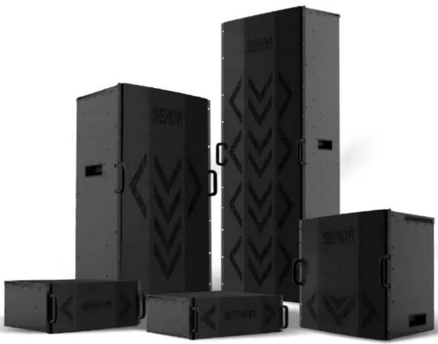
Exterior view of five black industrial storage cabinets with engraved patterns, arranged in a cluster (no visible text or symbols)This quick start guide provides basic instructions for setting up SEADA SolarWall Pro video wall controllers. For additional information about how to use the controllers, please see the User Manual, which is available on the CD included in this package.
Setup Steps
- Verify the Package Contents
- Hardware Overview
- Hardware Installation
- Software Installation & IP Setup on Control PC
- Configuration of Video Wall Management Software
- SWPro Management Software Brief Introduction
1. Verify the Package Contents
Please verify the package contents against the Packing List (Document No. SD-OP-005)
If any of the items in packing list is missing, please contact your reseller.
Document No. SD-MA-020
Document Version: 01

SolarWall Pro Controller Quick Start Guide
2. Hardware Overview
| Model: SWP02 (2U Chassis) | Model: SWP04 (4U Chassis) | |
| 4 5 6 7 1 2 3 | 4 5 6 7 1 2 3 | 1 2 |
| Model: SWP10 | Model: SWP16 | |
| 1 2 4 5 6 7 3 | 1 2 4 5 6 7 | 1. Slots for video input cards 2. Hybrid slots for either output or input cards 3. Power supply 4. RS232 serial connectors 5. RJ45 NET connector 6. Power switch 7. Keyboard and mouse USB connectors |
SolarWall Pro Controller Quick Start Guide
3. Hardware installation
3.1. Note
A computer running Microsoft Windows2000/XP/Vista/7/8/10 (not supplied) is required as a control PC for the SEADA controller.
3.2. Basic Connection
Connect the supplied power cable from the controller (Figure 1-3) to a power outlet.
Connect the SEADA video wall controller (Figure 1-5) to the control PC via Ethernet cable.
3.3. Connect Outputs to Displays
Connect the controller outputs to the video wall displays using the appropriate cables or adapters (not supplied).
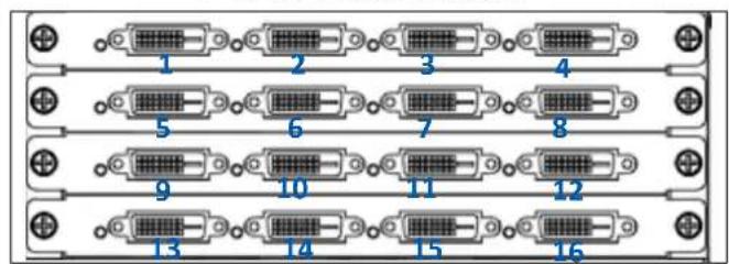
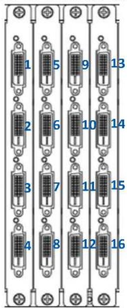
Please see Figure 2 below for the channel mapping between the video wall controller output ports and the video wall displays.
2 & 4U Chassis Output
text_image
1 2 3 4 5 6 7 8 9 10 11 12 13 14 15 16| 1 | 2 | 3 | 4 |
| 5 | 6 | 7 | 8 |
| 9 | 10 | 11 | 12 |
| 13 | 14 | 15 | 16 |
Video Wall Display
10 & 10 up Chassis Outputs
text_image
1 2 3 4 5 6 7 8 9 10 11 12 13 14 15 16Figure 2
SolarWall Pro Controller Quick Start Guide
3.4. Connect Input Sources to the Controller
Connect the Input sources to the SEADA video capture cards using the appropriate cables and adapters (not supplied).
SEADA Technology offers a comprehensive range of capture cards for use in our video wall controllers. Below is the list of all video capture cards and the connectors they use.
| Capture Card | Description | Signal Format | Connector Type | Illustration |
| SWPro-IN-DVI4 | 4 channel DVI capture card | DVI/HDMI | DVI-I (Dual Link) | 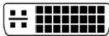 |
| SWPro-IN-HDMI4 | 4 channel HDMI capture card | HDMI/DVI | HDMI A | 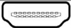 |
| SWPro-IN-VGA4 | 4 channel VGA capture card | RGB/YPbPr | D-Sub | 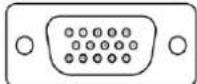 |
| SWPro-IN-DL2 | 2 channel Dual Link DVI capture card | DL-DVI, DVI/HDMI | DVI-I (Dual Link) | 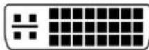 |
| SWPro-IN-SDI4 | 4 channel SDI capture card | 3G/HD/SD-SDI | BNC |  |
| SWPro-IN-DP2 | 2 channel DisplayPort capture card | DisplayPort 1.1 | DisplayPort | 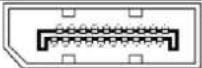 |
| SWPro-IN-DP60 | 1 channel DisplayPort capture card | DisplayPort 1.2 | DisplayPort | 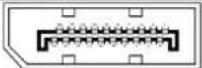 |
| SWPro-IN-UHM2 | 2 channel 4k@30 HDMI capture card | HDMI 1.4 | HDMI A | 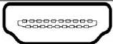 |
| SWPro-IN-UHM60 | 1 channel 4k@60 HDMI capture card | HDMI 2.0 | HDMI A | 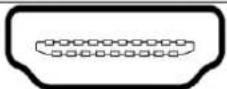 |
| SWPro-IN-HBT4 | 1 channel DisplayPort capture card | HDbaseT | RJ45 |  |
| SWPro-IN-IP16 | 16 channel 1080p IP decoding card | IP Streams | RJ45 |  |
| SWpro-IN-OF4 | 4 channel Optical Fiber capture card | Optical signal | LC | 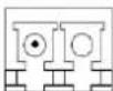 |
Figure 3
SolarWall Pro Controller Quick Start Guide
4. Software Installation & IP Setup on Control PC
Insert the SEADA Software CD into your control PC's CD-ROM drive to begin the installation. Double click the SolarWall Pro management software icon in software folder to start the installation. The SWPro software supports Microsoft Windows2000/XP/Vista/7/8/10
◆ Set up the static IP address on control PC
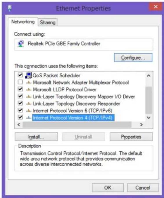
The default IP address of SWPro is 192.168.1.65. The control PC needs to be at the same range of controller in order to connect to the SWPro controller.
text_image
Ethernet Properties Networking Sharing Connect using: Realtek PCIe GBE Family Controller Configure... This connection uses the following items: ✓ QoS Packet Scheduler □ Microsoft Network Adapter Multiplexor Protocol ✓ Microsoft LLDP Protocol Driver ✓ Link-Layer Topology Discovery Mapper I/O Driver ✓ Link-Layer Topology Discovery Responder ✓ Internet Protocol Version 6 (TCP/IPv6) ✓ Internet Protocol Version 4 (TCP/IPv4) Install... Uninstall Properties Description Transmission Control Protocol/Internet Protocol. The default wide area network protocol that provides communication across diverse interconnected networks. OK Cancel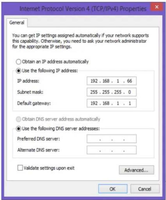
text_image
Internet Protocol Version 4 (TCP/IPv4) Properties General You can get IP settings assigned automatically if your network supports this capability. Otherwise, you need to ask your network administrator for the appropriate IP settings. Obtain an IP address automatically Use the following IP address: IP address: 192 . 168 . 1 . 66 Subnet mask: 255 . 255 . 255 . 0 Default gateway: 192 . 168 . 1 . 1 Obtain DNS server address automatically Use the following DNS server addresses: Preferred DNS server: . Alternate DNS server: . Validate settings upon exit Advanced... OK CancelFigure 4
- Open the 'Ethernet Properties' windows on the Control PC
- Highlight the TCP/IPv4 in Networking and click the Properties button to open the TCP/IPv4 Properties window
- Change the 'Obtain an IP address automatically' to 'Use the following IP address to set up a static IP address
IP address: any address between 192.168.1.1 and 192.168.1.255 except the address which has been taken by the Video Wall Controller
Subnet mask: 255.255.255.0
Default Gateway: 192.168.1.1.
SolarWall Pro Controller Quick Start Guide
5. Configuration of Video Wall Management Software
| Step1 | Switch on the SW Pro controllerOne long beep sound in a few seconds after the power on indicates the controller has finished its initialisation3 short beep sound indicates the controller is ready for operation | ||
| Step2 | Connect the control PC to the SW Pro controller using CAT cable between PC net port and controller net port (No.4 in Figure 1) | ||
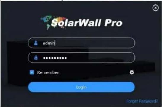
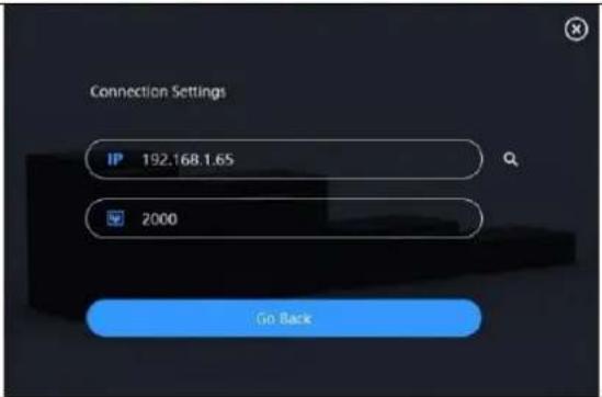
| Step3 | Double click the SWPro icononthe desktop that was created during the installation. The user login dialog box will appear.User Admin ID is 'admin' with the password of '123456'Press 'Setting' iconto set up the IP settings at '192.168.1.65' with port:2000Then press 'Go Back' button to go backPress 'Login' button to connect | ||
 |  | ||
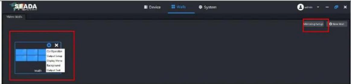
| Step4 | Once connected, the current configured layout will be shown in Video Walls Configuration Interface as belowUsers can change the configuration of the controller in 'Configuration' at the drop-down menu of the video wallUsers also can create new video wall by pressing 'New Wall' buttonSWPro supports MVWS (Multi Video Walls Support) technology, so users can control multi video walls on one SWPro controller | ||
 | |||
| In Configuration, users can set up the layout, bezel correction, resolution, frame rate and even set up the controller for LED video walls.If users create a new wall, after finishing the setup of configuration, users need to map the output channels (see Figure 2) at Output Setup in drop-down menu. | 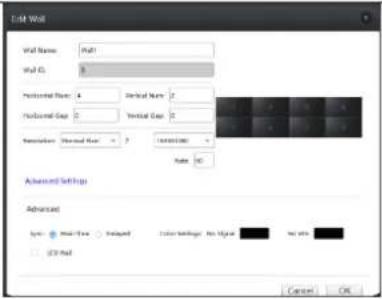 | 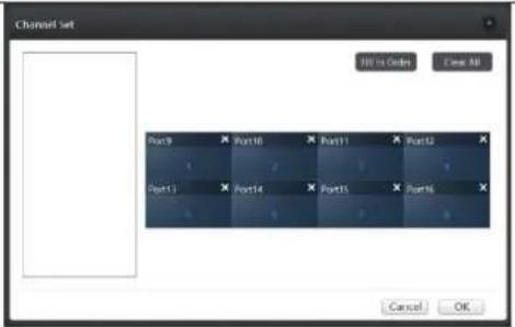 | |
SolarWall Pro Controller Quick Start Guide
Step5
Double click on video wall icon
- Preview is built in on SWPro controllers
- The default setting for Preview is off, users need to switch on the preview in order to preview all the inputs and video wall

text_image
SEADA Device Walls System admin Video Walk Wall1 Signal Signal1 Signal2 Signal3 Signal4 Signal5 Signal6 Signal7 Signal8 Preview Offline Reset Close All Save Preset Edit Wall Signal0 (0,0,04C2140) Signal Signal1 Signal 1 Signal 2 Signal 3 Signal 4 Signal 5 Signal 6 Signal 7 Signal 8 Signal4 Signal Group Preset Group Smooth Signal1 Signal2 Signal3 Signal4 Signal5 Signal6 Signal7 Signal8SolarWall Pro Controller Quick Start Guide
6. SWPro Management Software Brief Introduction
text_image
SEADA Device Walls System 1 Video Walls Wall1 Signal IF Signal Preset Loop Please Input Keywords Signal Signal Signal Signal Signal Signal Signal Signal Signal Signal Signal Signal Signal Signal Signal Signal Signal Signal Signal Signal Signal Signal Signal Signal Signal Signal Signal Signal Signal Signal Signal Signal Signal Signal Signal Signal Signal Signal Signal Signal Signal Signal Signal Signal Signal Signal Signal Signal Signal Signal 5 2 3 4 5 6 8 Signal Group Preset Group Smooth- Toolbar
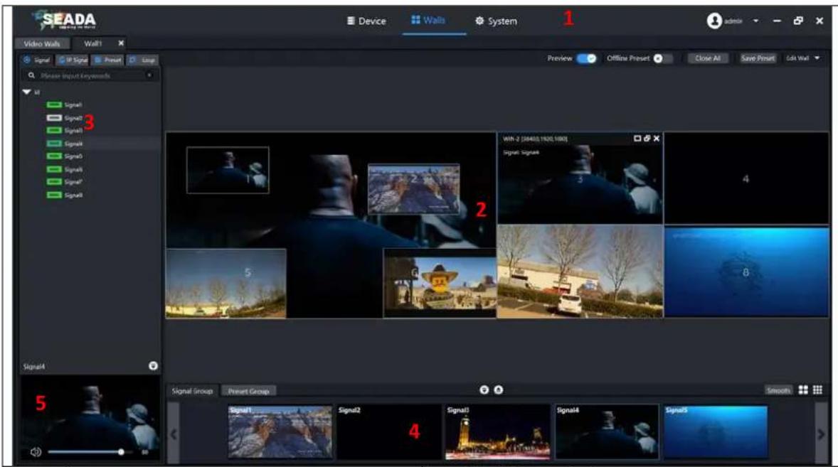
1.1. Device
1.2. Walls
1.3. System
- Video Wall Display area
- Application Toolbar
3.1. Signal Management
3.2. IP Streaming Setup
3.3. Preset Layout
3.4. Loop Setup
- Input Signals and Preset Layout Preview Bar
- Individual Input Preview and Audio Volume Control
Display Input sources on the Video Wall
- Simply drag and drop the input source from the 'Signal' at the 'Application Toolbar' onto the Video Wall Display area.
- Highlight the signal source needed to be displayed from the 'Signal' at the 'Application Toolbar' and draw a window on the video wall display area using mouse.
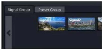
- Simply drag and drop the input source from the 'Signal Group' at the Preview Bar onto the Video Wall Display area.
text_image
Signal Group Preset Group Signal1 Signal2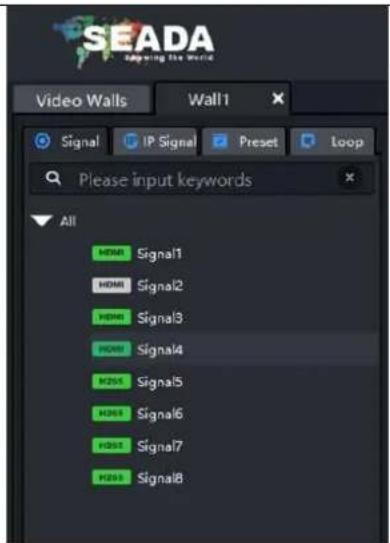
text_image
SEADA Applying the world Video Walls Wall 1 Signal IP Signal Preset Loop Please input keywords All HDMI Signal1 HDMI Signal2 HDMI Signal3 HDMI Signal4 H201 Signal5 H203 Signal6 H201 Signal7 H203 Signal8For further understanding of using SolarWall Pro Controllers, setting up IP streaming and SWPro software, please refer to SWPro Management Software User Manual (Document number: SD-MA-021) and the datasheet.