G88-HDMI - Processor SEADA - Free user manual and instructions
Find the device manual for free G88-HDMI SEADA in PDF.


User questions about G88-HDMI SEADA
0 question about this device. Answer the ones you know or ask your own.
Ask a new question about this device
Download the instructions for your Processor in PDF format for free! Find your manual G88-HDMI - SEADA and take your electronic device back in hand. On this page are published all the documents necessary for the use of your device. G88-HDMI by SEADA.
USER MANUAL G88-HDMI SEADA
- Do not fix the device to any surface which is a heat source to avoid over heating
- Do not cover the surface or ventilation grills of the device to avoid over heating
1. Verify the package contents
Please verify the package contents against the List Below
-
G88 Controller x1
-
Serial Cable x1
-
Power Cable x1
-
Network Cable x1
-
Software Disk x1
-
Remote Control x1
2. Set up the G88
I. Connect the power cable to the unit and power it up
II. Connect the outputs to the screens of the video wall
III. Connect all the video sources to the inputs of the devices
Note: G88 remembers the settings used on the device before power off. The default setting for the new unit is 2x4 video wall with input 1 across the 8 screens. All outputs are set at resolution of 1920 x 1080@60.
3. Run the software on control PC
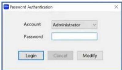
Users can run the G88H.exe software directly without installation. Software is on the disk in the package or you can download it from the SEADA website. Double click the G88H software to get the Dialog box as below
text_image
Password Authentication Account Administrator Password Login Cancel ModifyDefault password for Administrator:111111
Default password for User: 000000
Type in the password and log in
4. Connect through Serial Port

Connect the G88 with a serial cable to the control PC (cable included in the package)
If the software was connected via UART (RS232) last time, software will connect to the G88 automatically vis RS232. If it was used at Network last time, a 'Network Timeout' error message will be shown on screen and users need to set up as below for RS232 connection in the software
- Choose 'UART' instead of 'Network'
- Select the COM port from the Port dropdown menu
- Press 'Disconnected' button to connect
5. Connect through Network
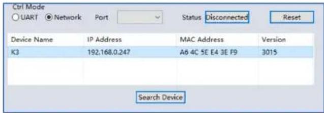
The default IP address for G88 controller is 192.168.0.247, Users need to change the IP address of the control PC to static IP address and the same network segment as the G88 at TCP/IPv4 in Ethernet Properties
IP address: any address between 192.168.0.2 and 192.168.0.254 except the address which has been taken by the G88
O Subnet mask: 255.255.255.0, Default Gateway: 192.168.0.1
G88 Quick Start Manual
text_image
Ctrl Mode ○ UART ● Network Port Status Disconnected Reset Device Name IP Address MAC Address Version K3 192.168.0.247 A6 4C 5E E4 3E F9 3015 Search DeviceConnect the G88 with a CAT cable to the control PC (cable included in the package)
If the software was connected via Network last time, software will connect to the G88 automatically via network. If it was used at serial port last time, a 'Please select COM port' error message will be shown on screen
and users need to set up as below for Network connection in the software
- Choose 'Network' instead of 'UART'
- Press 'Search Device' button to find the G88 on the network
• Highlight the device Press 'Disconnected' button to connect
6. Set up the video wall
text_image
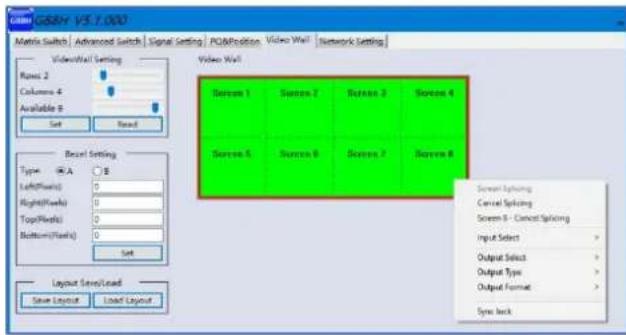
G88H V5.1.000 Matrix Switch | Advanced Switch | Signal Setting | POA/Position | Video Wall | Network Setting Video Wall Setting Raze 2 Columns 4 Available 6 Set Reset Reset Setting Type: A/A B Left(Flare) 0 Right(Flare) 0 Top(Flare) 0 Bottom(Flare) 0 Set Layout Save/Load Save Layout Label Layout Video Wall Screen 1 Screen 2 Screen 3 Screen 4 Screen 5 Screen 6 Screen 7 Screen 8 Screen Splicing Cancel Splicing Screen 9 - Cancel Splicing Input Select > Output Select > Output Type > Output Format > Sync backOnce connected, G88 will load the settings used from last time. The default setting for the new unit out of package is 2x4 video wall with input 1 across the 8 screens. All outputs are set at resolution of 1920 x 1080@60.
Select the 'Video Wall' tab and users can set up the video wall layout in 'VideoWall Setting', Bezel correction in 'Bezel Setting' and Save/Load preset video wall layouts in 'Layout Save/Load'
Right click on the video wall, users can use the tools in
'Dropdown menu' to set up the video walls.

natural_image
Fashion show collage of a model wearing a patterned outfit, displayed on a runway (no visible text or symbols)- Screen Splicing - This combines the selected screens into one and displays the selected input across all the splicing screens. For example, in the setup 2x4 at left, if all of them are spliced, then the input selected by the user will be displayed across all the 8 screens.
(Users can create more than one video wall on G88. e.g. they can create two 2x2 video walls instead of one 2x4 video wall or 3, 4 independent video walls) - Cancel Splicing – This will cancel the video wall and revert to the matrix switching mode
- Screen – Cancel Splicing— This will cancel the very screen and revert only that screen to the matrix switching mode to form a Picture in Picture effect
- Input Select –This allows the user to control which input is displayed on video wall
-
Output Select – The user can control which screen should be mapped to which output (only available in matrix mode)
-
Output Type – Allows the user to adjust the type of the output (only available in matrix mode)
- Output Format – Controls the resolution of the output (only available in matrix mode)
- Sync lock– to form sync between different screens in the same video wall
This quick start manual provides basic instructions for setting up SEADA G88 video wall controllers. For additional information about how to use the controllers, please refer to the G88 User Guide (SD-EN-015), which is available on the CD included in this package.