
RSC-4H - Uncategorized AIC - Free user manual and instructions
Find the device manual for free RSC-4H AIC in PDF.


| Product Type | Network Switch |
| Brand | AIC |
| Model | RSC-4H |
| Category | Uncategorized |
| Dimensions (W x D x H) | 30 x 20 x 4.5 cm |
| Weight | 1.5 kg |
| Power Supply | AC 100-240V, 50-60Hz |
| Power Consumption | 30 W |
| Ports | 4 x RJ45 10/100/1000 Mbps, 1 x SFP |
| Switching Capacity | 10 Gbps |
| Operating Temperature | 0°C to 40°C |
| Storage Temperature | -20°C to 60°C |
| Humidity | 10% to 90% non-condensing |
| Safety Certifications | CE, FCC |
| Installation | Desktop or rack mountable (brackets included) |
| Management | Web interface, SNMP |
| Maintenance | Clean with a soft, dry cloth. Avoid liquids. |
| Spare Parts | Power adapter, mounting brackets, rubber feet |
| Manual Languages | English (EN), 57 pages |
| Warranty | Limited 1-year warranty |
Frequently Asked Questions - RSC-4H AIC
User questions about RSC-4H AIC
0 question about this device. Answer the ones you know or ask your own.
Ask a new question about this device
Download the instructions for your Uncategorized in PDF format for free! Find your manual RSC-4H - AIC and take your electronic device back in hand. On this page are published all the documents necessary for the use of your device. RSC-4H by AIC.
USER MANUAL RSC-4H AIC
SAFETY INSTRUCTIONS ......ii
Chapter 1. Prodcut Introduction ......1
1.1 Box Content .... 1
1.2 Specifications .... 2
1.3 General Information ....3
Chapter 2. Hardware Installation ......6
2.1 Removing and Installing Top Cover ....6
2.2 Removing/Installing a Drive Tray ....7
2.3 Installing/ Removing a Hard Disk Drive ....8
2.4 Removing and Installing a PSU Module ....9
2.5 Removing and Installing a Fan Module ....10
2.6 Removing and Installing HDD Backplane ....11
2.7 Tool-less Blade Slide Installation Instruction ....12
Chapter 3. Hardware Instruction ...... 19
3.1 HARDWARE DESIGN SPECIFICATION ....19
Chapter 4. HDD Blackplane Instruction ...... 24
4.1 Expender firmware update through smart console port ....24
4.2 Update the expander firmware through in-band. 37
4.3 12G expander EDFB setting ....41
4.4 Slot HDD power setting ....43
4.5 HDD BP thermal sensor temperature setting ....48
Chapter 5. Technical Support.... 51
AIC
Copyright © 2015 AIC, Inc. All Rights Reserved.
This document contains proprietary information about AIC products and is not to be disclosed or used except in accordance with applicable agreements.
PREFACE
- Copyright
No part of this publication may be reproduced, stored in a retrieval system, or transmitted in any form or by any means, electronic, mechanical, photo-static, recording or otherwise, without the prior written consent of the manufacturer.
- Trademarks
All products and trade names used in this document are trademarks or registered trademarks of their respective holders.
- Changes
The material in this document is for information purposes only and is subject to change without notice.
- Warning
- A shielded-type power cord is required in order to meet FCC emission limits and also to prevent interference to the nearby radio and television reception. It is essential that only the supplied power cord be used.
- Use only shielded cables to connect I/O devices to this equipment.
- You are cautioned that changes or modifications not expressly approved by the party responsible for compliance could void your authority to operate the equipment.
- Disclaimer
AIC shall not be liable for technical or editorial errors or omissions contained herein. The information provided is provided "as is" without warranty of any kind. To the extent permitted by law, neither AIC or its affiliates, subcontractors or suppliers will be liable for incidental, special or consequential damages including downtime cost; lost profits; damages relating to the procurement of substitute products or services; or damages for loss of data, or software restoration. The information in this document is subject to change without notice.
SAFETY INSTRUCTIONS
- Before getting started, please read the following important cautions:
- All cautions and warnings on the equipment or in the manuals should be noted.
- Most electronic components are sensitive to electrical static discharge. Therefore, be sure to ground yourself at all times when installing the internal components.
- Use a grounding wrist strap and place all electronic components in static-shielded devices. Grounding wrist straps can be purchased in any electronic supply store.
- Be sure to turn off the power and then disconnect the power cords from your system before performing any installation or servicing. A sudden surge of power could damage sensitive electronic components.
- Do not open the system's top cover. If opening the cover for maintenance is a must, only a trained technician should do so. Integrated circuits on computer boards are sensitive to static electricity. Before handling a board or integrated circuit, touch an unpainted portion of the system unit chassis for a few seconds. This will help to discharge any static electricity on your body.
- Place this equipment on a stable surface when install. A drop or fall could cause injury.
- Please keep this equipment away from humidity.
- Carefully mount the equipment into the rack, in such manner, that it won't be hazardous due to uneven mechanical loading.
- This equipment is to be installed for operation in an environment with maximum ambient temperature below 35^ C.
- The openings on the enclosure are for air convection to protect the equipment from overheating. DO NOT COVER THE OPENINGS.
- Never pour any liquid into ventilation openings. This could cause fire or electrical shock.
- Make sure the voltage of the power source is within the specification on the label when connecting the equipment to the power outlet. The current load and output power of loads shall be within the specification.
- This equipment must be connected to reliable grounding before using. Pay special attention to power supplied other than direct connections, e.g. using of power strips.
- Place the power cord out of the way of foot traffic. Do not place anything over the power cord. The power cord must be rated for the
product, voltage and current marked on the product's electrical ratings label. The voltage and current rating of the cord should be greater than the voltage and current rating marked on the product.
- If the equipment is not used for a long time, disconnect the equipment from mains to avoid being damaged by transient over-voltage.
- Never open the equipment. For safety reasons, only qualified service personnel should open the equipment.
- If one of the following situations arise, the equipment should be checked by service personnel:
-
The power cord or plug is damaged.
-
Liquid has penetrated the equipment.
-
The equipment has been exposed to moisture.
-
The equipment does not work well or will not work according to its user manual.
-
The equipment has been dropped and/or damaged.
-
The equipment has obvious signs of breakage.
-
Please disconnect this equipment from the AC outlet before cleaning. Do not use liquid or detergent for cleaning. The use of a moisture sheet or cloth is recommended for cleaning.
Product features and specifications are subject to change without notice.
Chapter 1. Prodcut Introduction
1.1 Box Content
Before removing the subsystem from the shipping carton, visually inspect the physical condition of the shipping carton. Exterior damage to the shipping carton may indicate that the contents of the carton are damaged. If any damage is found, do not remove the components; contact the dealer where the subsystem was purchased for further instructions. Before continuing, first unpack the subsystem and verify that the contents of the shipping carton are all there and in good condition.
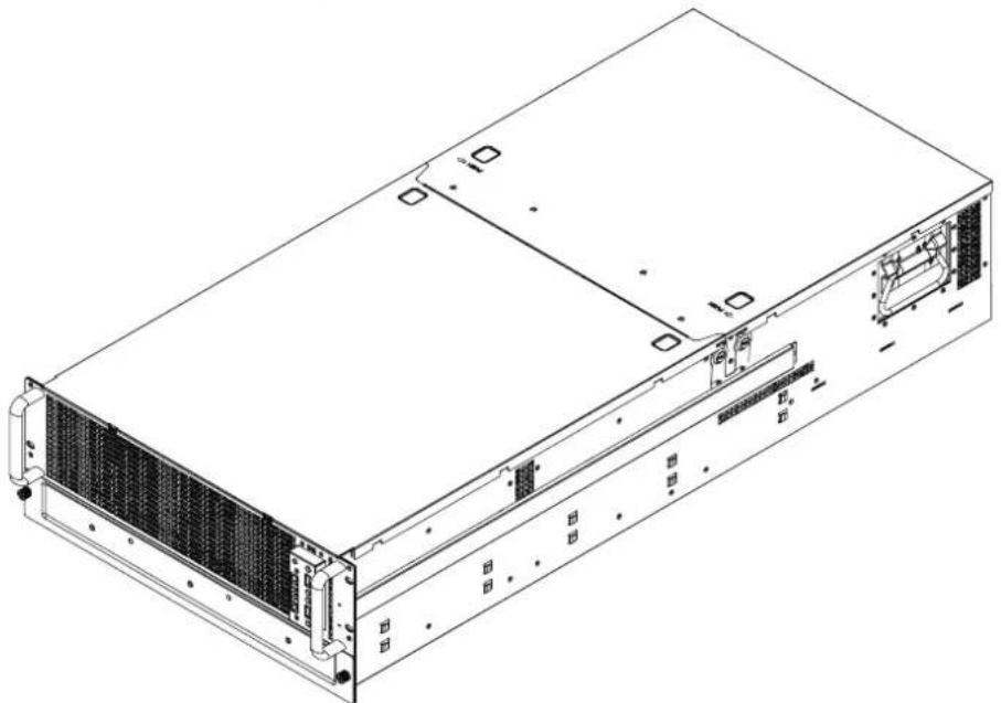
natural_image
Technical line drawing of a server rack unit with ventilation grilles and drive bays (no text or symbols)• Enclosure( Power supply, fan, 60 x 3.5" HDD tray included)
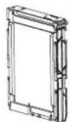
• 3.5" HDD Tray
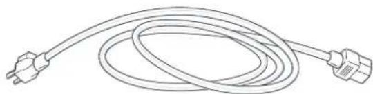
natural_image
Line drawing of a coiled electrical plug with two terminal connectors (no text or symbols)• Power cord • Screws kit x 1pcs
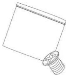
natural_image
Simple line drawing of a screw and nut assembly (no text or symbols)• (Include console serial cable)
natural_image
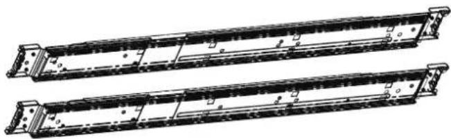
Technical line drawing of two identical mechanical components with mounting flanges (no text or symbols)- Slide rail x 1set
RSC-4H User's Manual
◆ PACKAGE CONTENT MAY VARY PER REGION.
1.2 Specifications
| Dimensions(W x D x H)(with chassis ears) | mm : 480 x 955 x 176 | ||
| inches : 18.9 x 37.6 x 7nches | |||
| Industry Standard | EIA-RS310DIA | ||
| Materials | Heavy-duty preplated SPGC cold-rolled steel | ||
| Color | Front Panel : Black | ||
| Cooling | Middle : 4 x 80x80x38mm hot-swap fans | ||
| Rear : 2 x 60x60x38mm easy-swap fans | |||
| Power Supply | 1890W 3+1 hot-swap redundant 80+ | ||
| Expansion | 7 x PCI slots (full height, full length) | ||
| Buttons & Ports | Power on/off, System reset and 2 x USB3300 | ||
| Indicators | Power LAN, HDDs, and System ID LEDs | ||
| System Board | 12"(W) x 13"(D) E-ATX/SSI EEB 3.6 compliant MB | ||
| Drive Bay | External | 2.5" hot-swap | 2 (up to 6 as an option) |
| Internal | 3.5" hot-swap | 60 | |
| Temperature | 0°C(32°F) ~ 50°C(122°F) | ||
| Humidity | 5%~95% non-condensing | ||
| Gross Weight | (w/ PSU & Rail) | 35 kgs / 77 lbs | |
| Packaging Dimension | (W x D x H) | mm : 593 x 1211 x 386 | |
| Cubic Feet | 9.8 | ||
| Reference Container Loading | 20' | 97 | |
| 40' | 199 | ||
| 40' H | 240 | ||
| Backplane | 20 ports HDD B/P with SAS 6G LSI 2x28 expander on board | ||
RSC-4H User's Manual
Chapter 1 Product Introduction
1.3 General Information
RSC-4H is a 4U rackmount chassis with external hot-swap HDD 60 x 3.5" HDD and single 6G expander on HDD Backplane which is a high performance server storage product.
- Front Panel

text_image
HDD Failed LED (red) USB ports x 2 HDD PAIL HDD PAIL HDD PAIL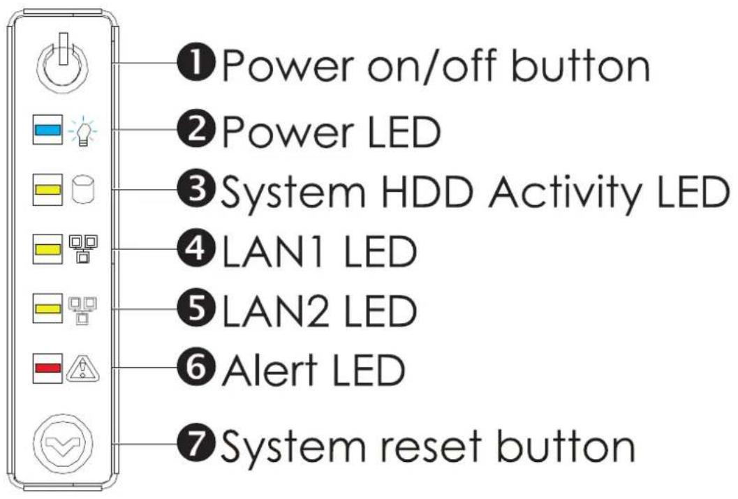
text_image
①Power on/off button ②Power LED ③System HDD Activity LED ④LAN1 LED ⑤LAN2 LED ⑥Alert LED ⑦System reset buttonChapter 1 Product Introduction
- Rear Panel
text_image
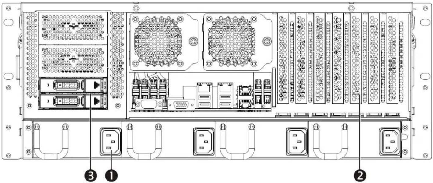
Technical diagram of an internal network device with labeled ports and connectors, showing internal components like CPU, I/O ports, and Ethernet ports.① Hot-swap redundant power supplies
② 7 sets PCI slots attribute to expansion and scalability
③ 6 sets 2.5" hot-swap HDD supported
Chapter 1 Product Introduction
• Major Components
text_image
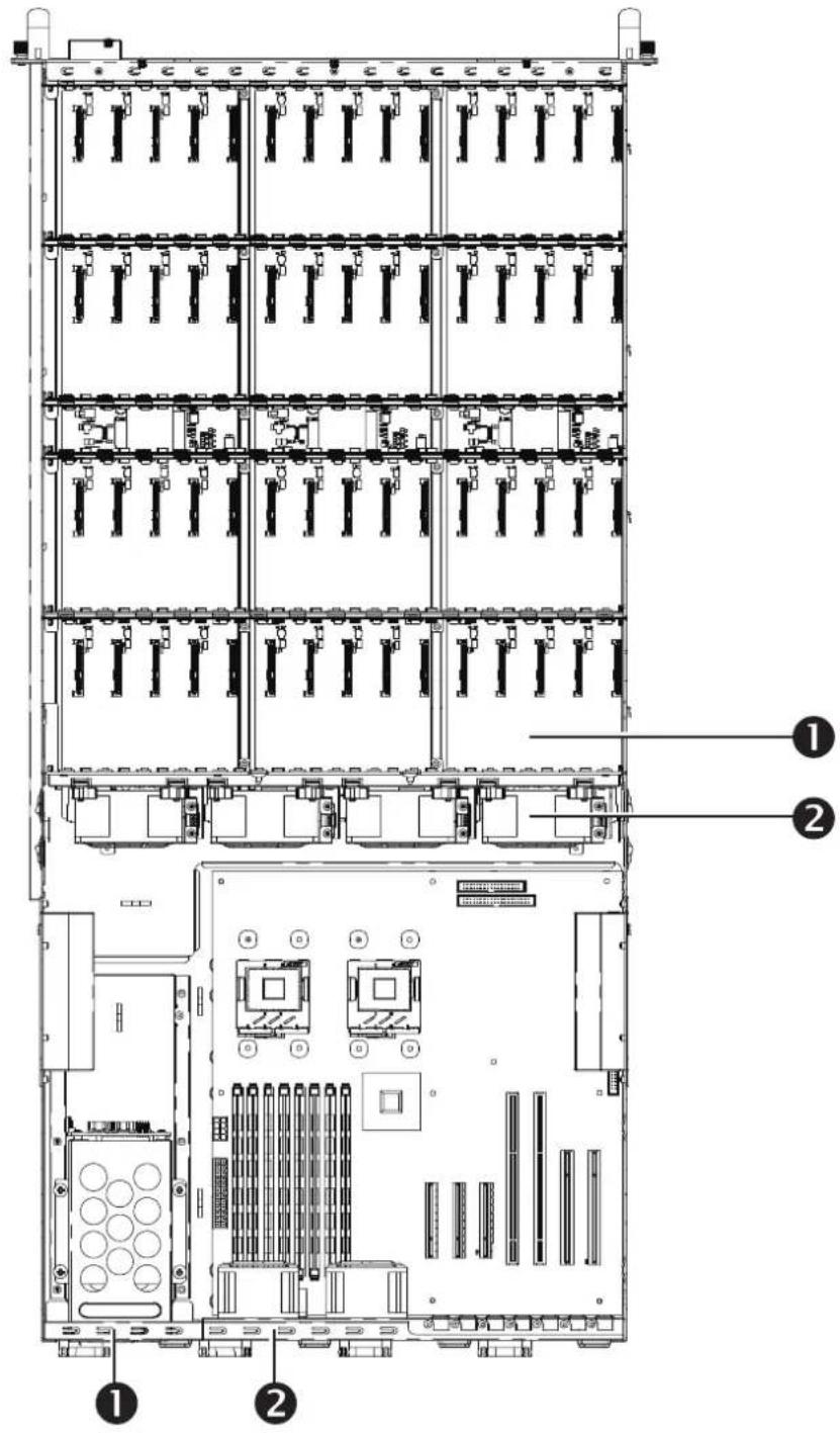
Technical diagram of a server rack with labeled components, showing front, internal, and exterior views.① 60 external hot-swap HDD supported Front:60 3.5''HDD
Rear:6 2.5''HDD
② 4 hot-swap fans in the middle side and 2 in the rear side for optimized cooling.
RSC-4H User's Manual
Chapter 2. Hardware Installation
This chapter provides detailed instructions on hardware installation.
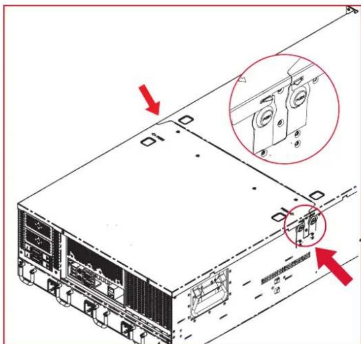
2.1 Removing and Installing Top Cover
Pushing release button on both side and slide forward the top cover to open cover.
text_image
Technical diagram of a server rack with labeled ports and highlighted internal components, showing red arrows indicating assembly or status.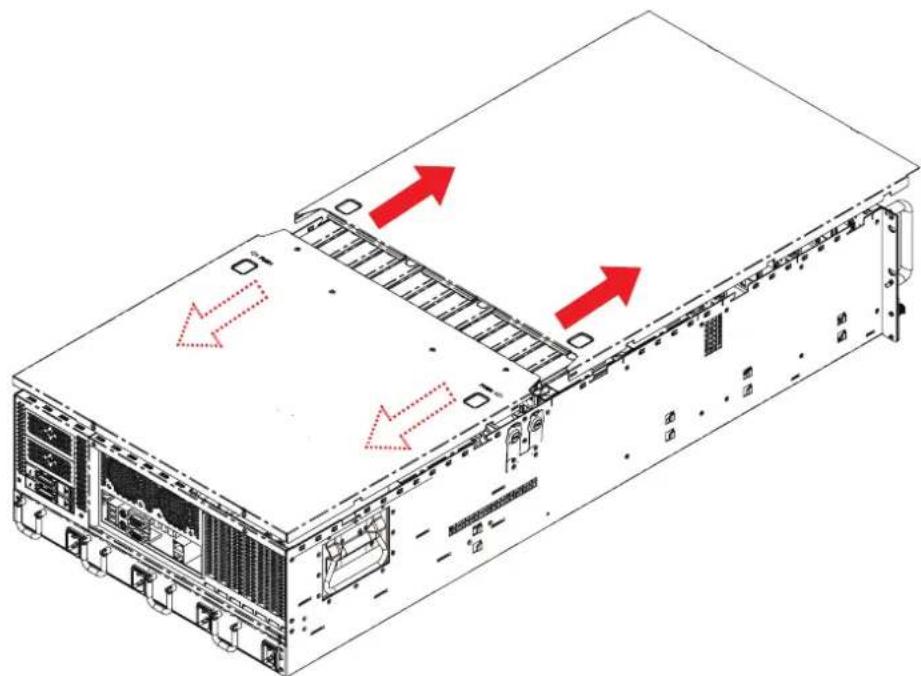
natural_image
Isometric diagram of a server rack with red arrows indicating directional movement or flow, no text or symbols present.2.2 Removing/Installing a Drive Tray
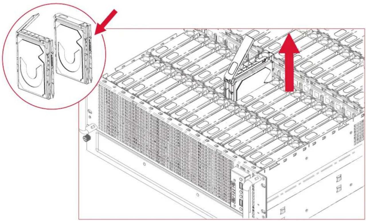
Hold the latch on top of the hard disk drive tray. Pull it out of the chassis.
natural_image
Technical line drawing of a server rack with internal components and mounting bracket (no text or symbols)2.3 Installing/ Removing a Hard Disk Drive
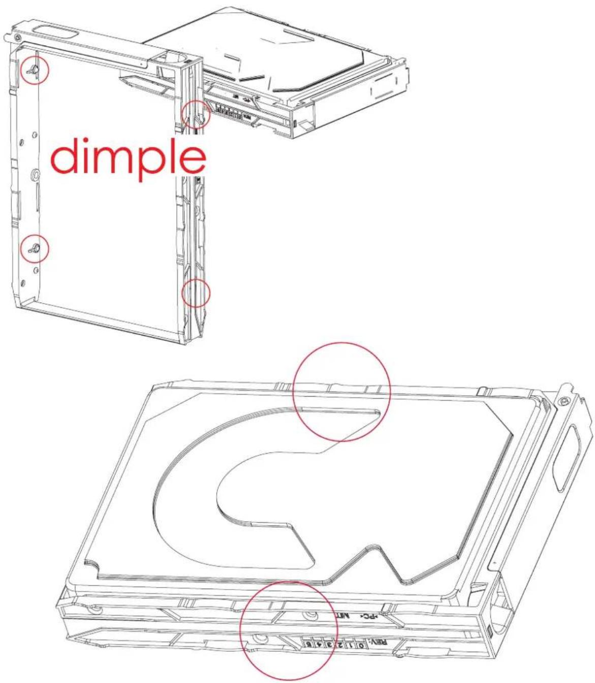
Place the HDD into the hard disk carrier tray.
Please check if the screw holes on HDD match the dimples on HDD tray.
text_image
dimple Rev 01 23 46 Rev 01 23 46NOTE: THERE ARE 2 SCREWS HOLES RESERVED.
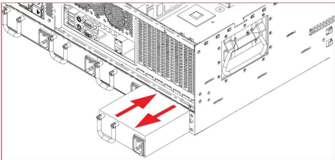
2.4 Removing and Installing a PSU Module
2.4.1 Removing a PSU module
Grasp the tray handle tab. Pull the PSU module tray gently and firmly until it clears the enclosure chassis.
2.4.2 Installing a PSU Module
Slide in PSU module. Make sure the latch on the module is fully hooked on the PSU housing.
natural_image
Technical line drawing of a server rack with highlighted internal components and red directional arrows indicating data flow (no text or symbols present)2.5 Removing and Installing a Fan Module
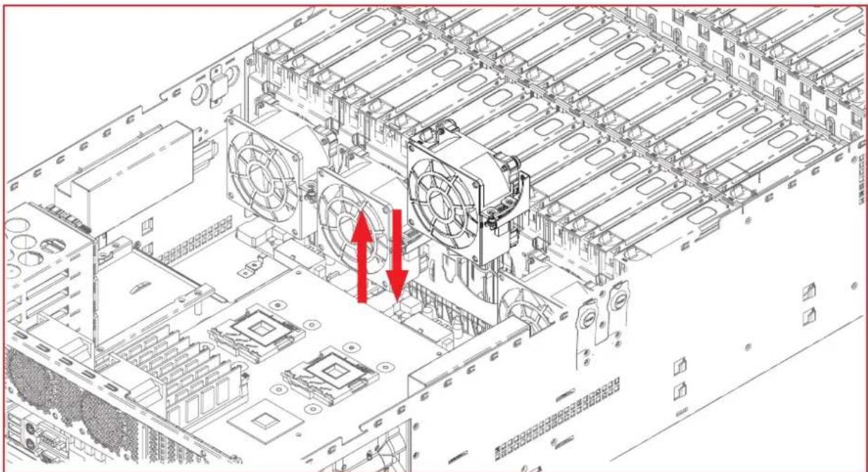
2.5.1 Removing a fan module
Grabbing and removing the fan module from the fan slot.
natural_image
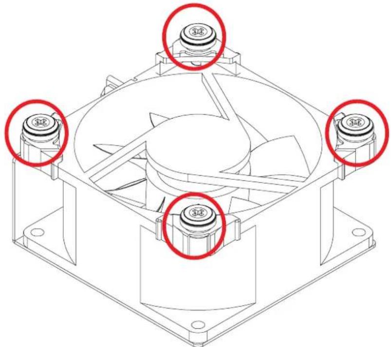
Technical line drawing of a computer motherboard with visible CPU socket and fan assembly (no text or symbols)Pull the fan module up gently and taking out the fan module by removing rubbers out from the fan bar.
natural_image
Technical line drawing of a computer fan assembly with four red-circled ports (no text or symbols)2.5.2 Installing a Fan Module
Make sure the 4 rubbers and connector insert firmly while fan module is inserted.
RSC-4H User's Manual
Chapter 2 Hardware Installation
2.6 Removing and Installing HDD Backplane
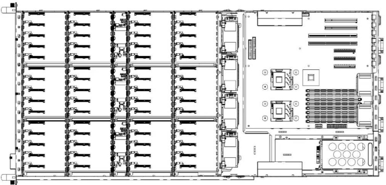
2.6.1 Removing HDD Backplane
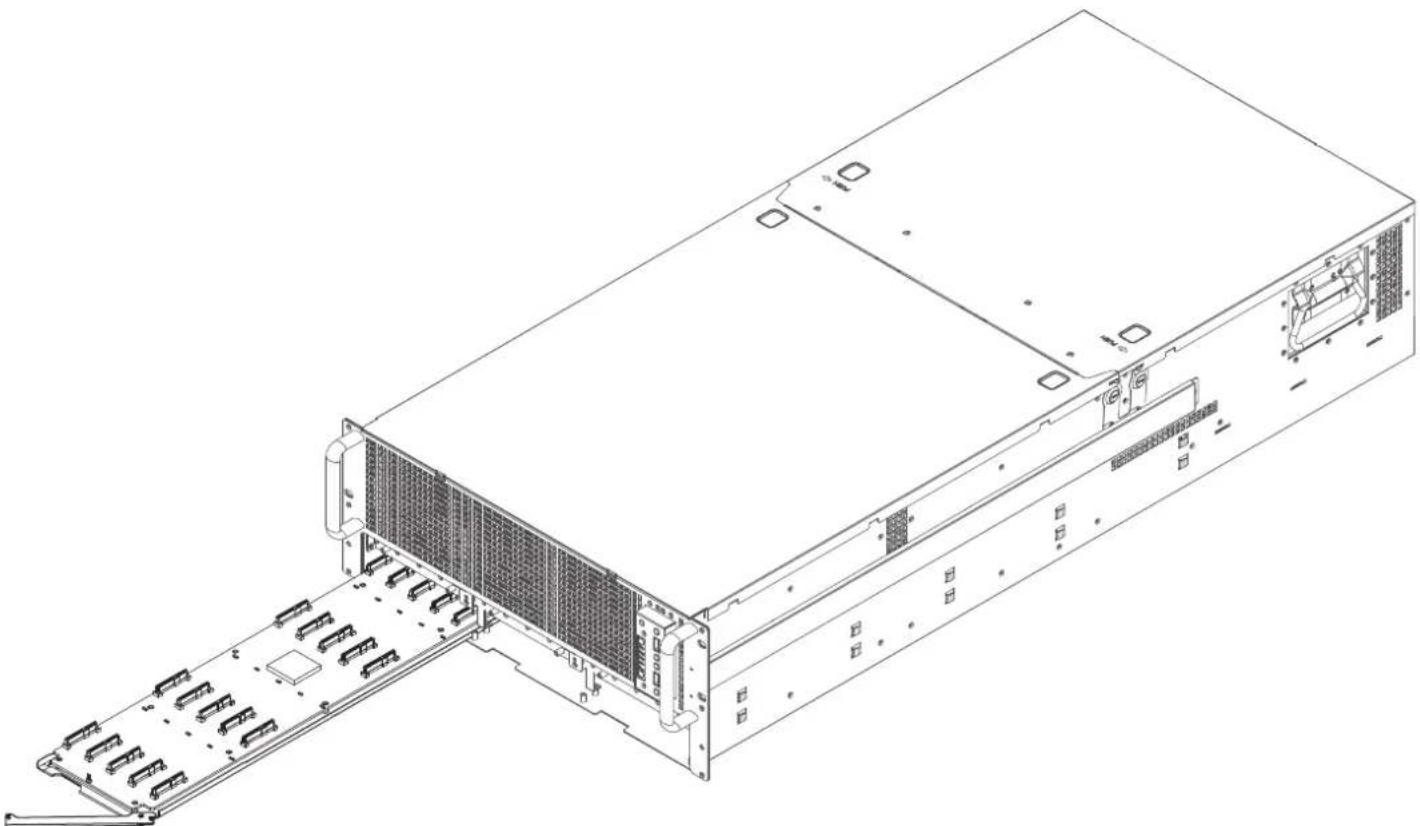
Unplugging all connectors & HDDs from HDD backplane.
natural_image
Technical line drawing of a server rack with multiple drive bays and internal components (no text or labels)Hold the lever to pull the Backplane out of chassis.
natural_image
Technical line drawing of a server rack with ventilation grilles and drive bays (no text or symbols)2.6.2 Installing a HDD Backplane
To install Backplane, follow the reverse order.
RSC-4H User's Manual
Chapter 2 Hardware Installation
2.7 Tool-less Blade Slide Installation Instruction
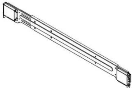
Separate the tool-less slide rail
natural_image
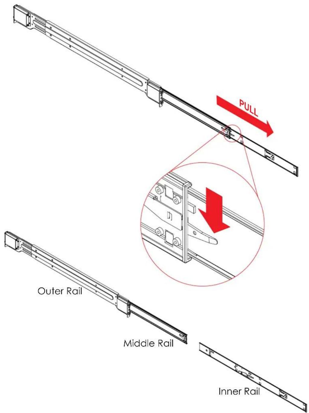
Technical line drawing of a mechanical component with flanged ends and internal channels (no text or symbols)2.7.1 Pull the inner rail out of the outer rail until it is fully extended. Press the locking tab down to release the inner rail.
text_image
PULL Outer Rail Middle Rail Inner RailChapter 2 Hardware Installation
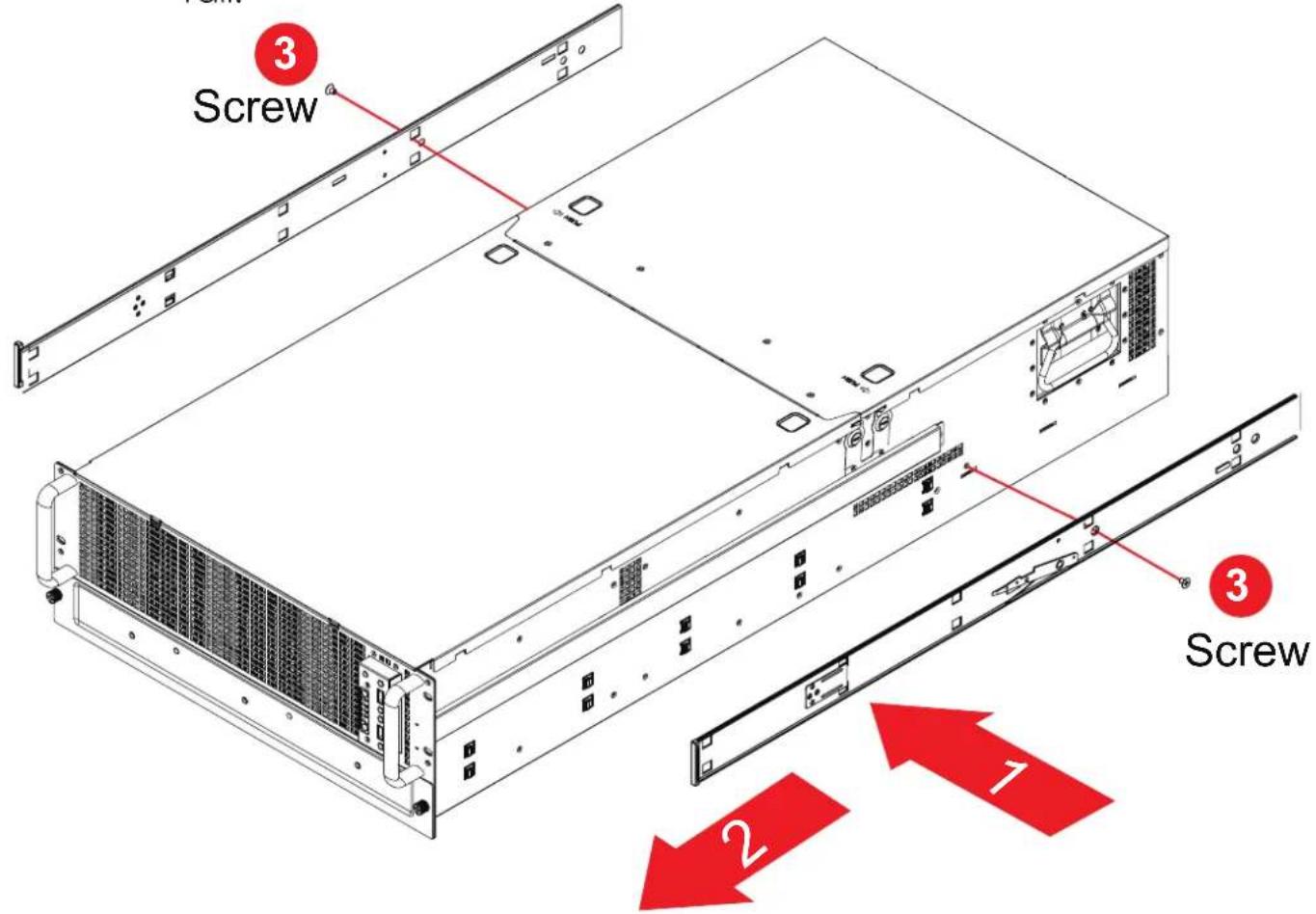
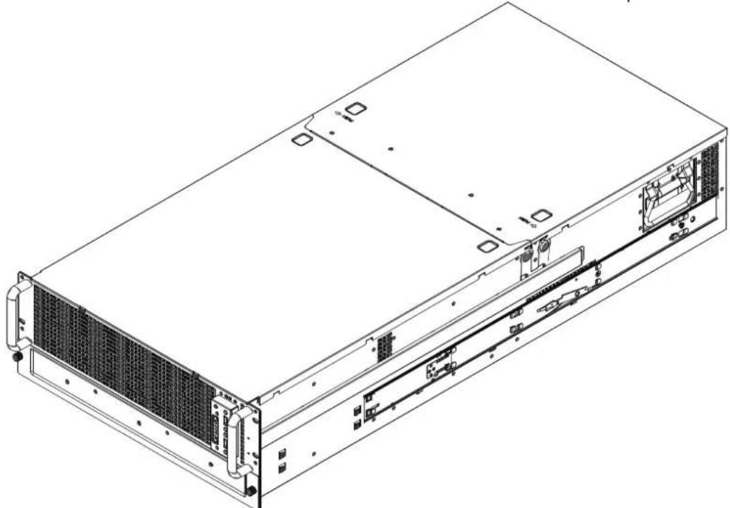
2.7.2 Place the inner rail firmly against the side of the chassis. Make sure that the hooks are straight and aligned with the holes in the inner rail.
text_image
Screw 3 Screw 2 1 3Slide the inner rail forward until it clicks into the locked position.
natural_image
Technical line drawing of a server rack unit with ventilation grilles and drive bays (no text or labels)RSC-4H User's Manual
Chapter 2 Hardware Installation
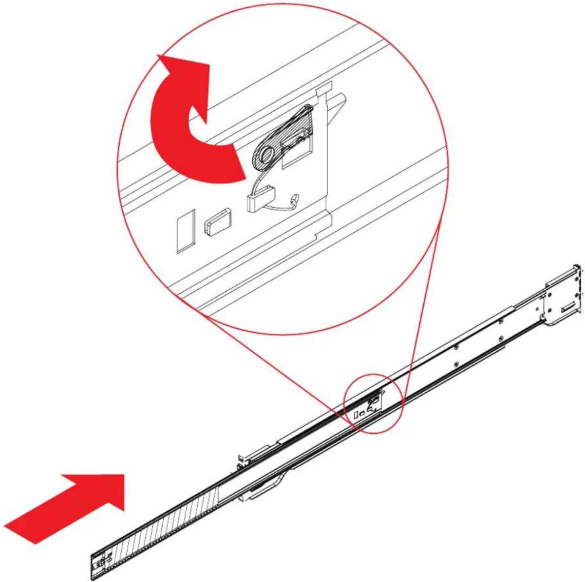
2.7.3 Press the locking tab and push the middle rail back into the outer rail.
text_image
Technical diagram showing installation of a mechanical component with red arrows indicating direction and magnified detail viewChapter 2 Hardware Installation
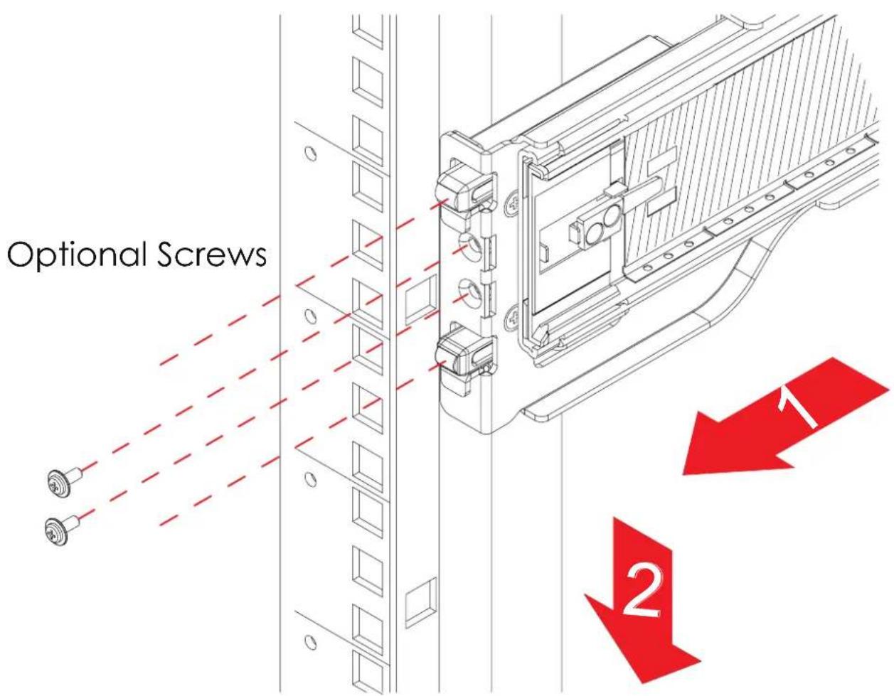
2.7.4 Hang the hooks of the rails on the rack holes and if necessary, secure with screws.
text_image
Optional Screws 1 2Chapter 2 Hardware Installation
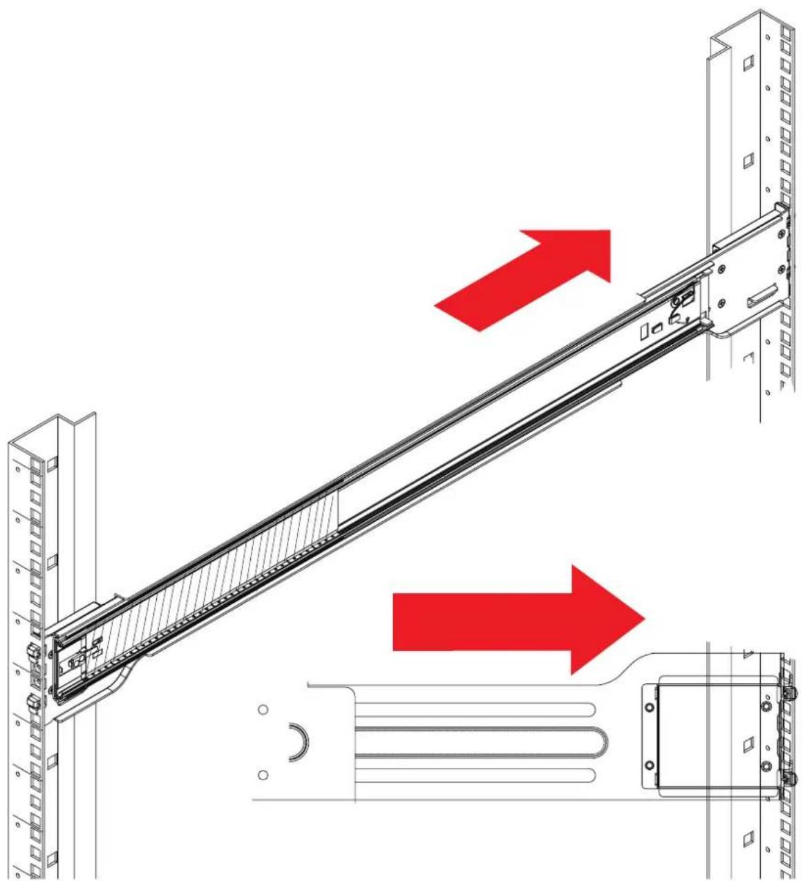
2.7.5 Repeat step 2.7.4 to mount the four ends, extending the rails as necessary.
natural_image
Technical line drawing of a mechanical assembly with red arrows indicating motion or force directions (no text or symbols present)Chapter 2 Hardware Installation
2.7.6 Pull the middle rail out of the front of the outer rail and make sure that the ball bearing shuttle is locked at the front of the middle rail.
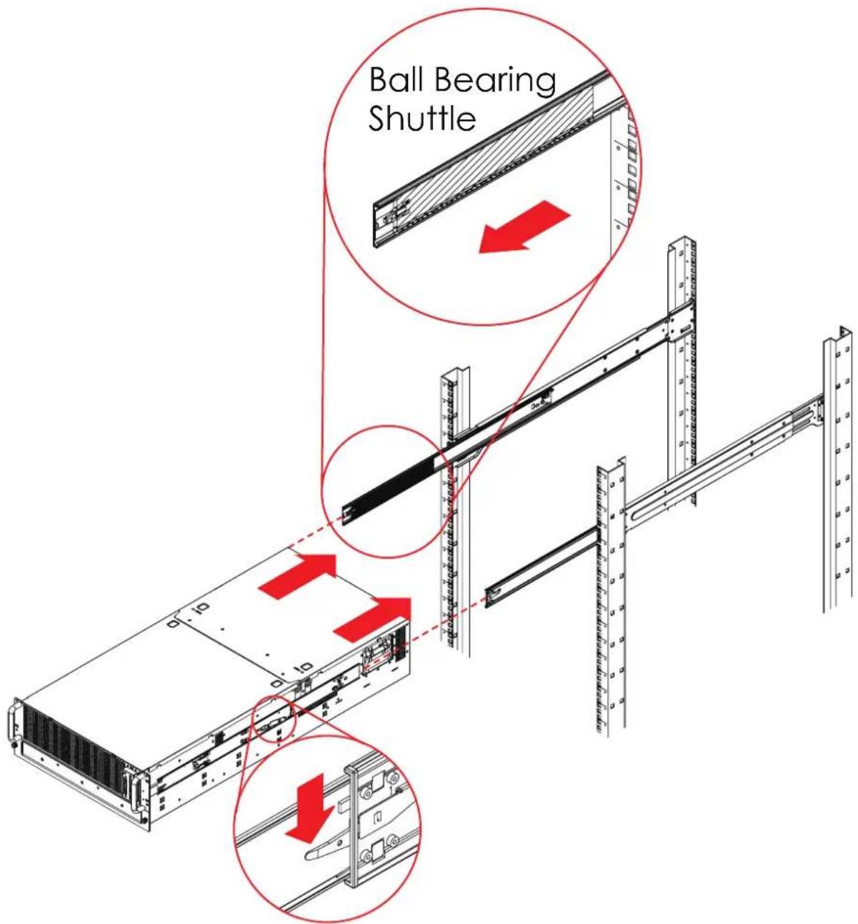
text_image
Ball Bearing ShuttleAlign the inner rails with the middle rails and then push evenly on both sides of the chassis until it clicks into the fully extended position.
Chapter 2 Hardware Installation
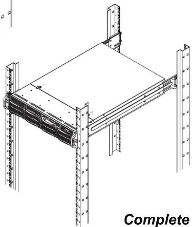
2.7.7 Depress the locking tabs on both sides of the chassis simultaneously and push the chassis all the way into the rear of the rack.
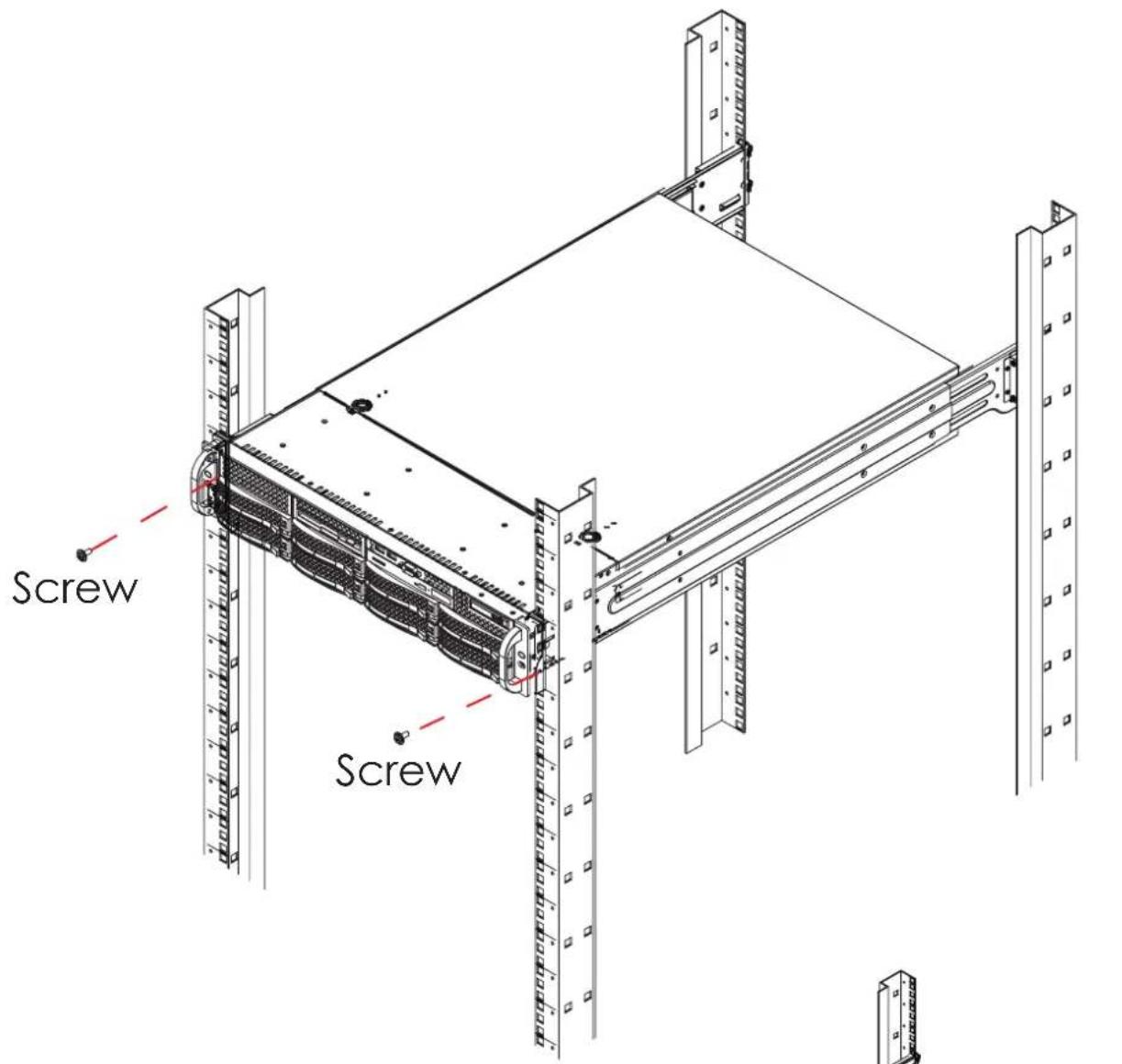
text_image
Screw ScrewIf additional security is required, secure the chassis handles to the front of the rack with two screws (optional).
natural_image
Technical line drawing of a server rack unit with multiple vertical racks and a flat top panel (no text or symbols)RSC-4H User's Manual
Chapter 3. Hardware Instruction
This chapter provides detailed instruction guide on hardware instruction
3.1 HARDWARE DESIGN SPECIFICATION
3.1.1 Placement
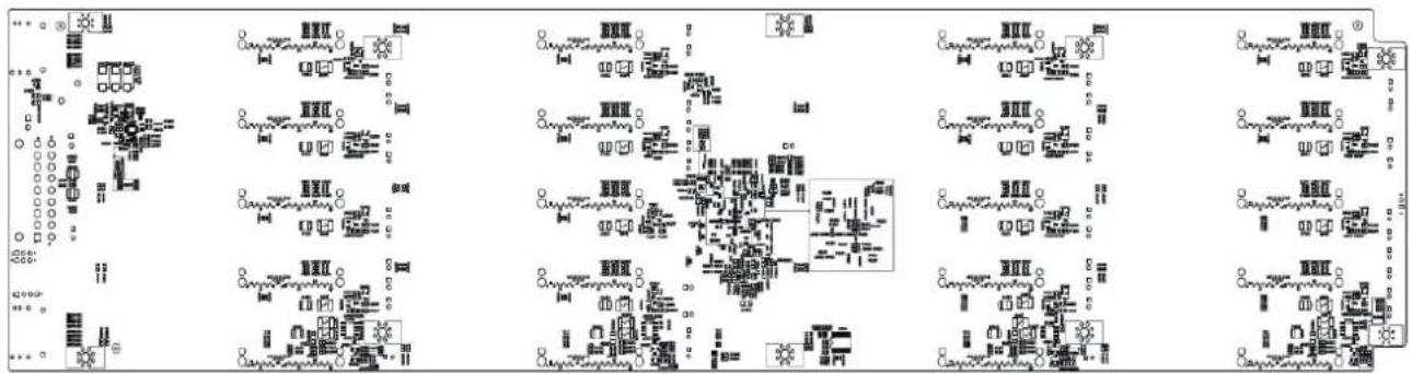
PCBA Placement
TOP
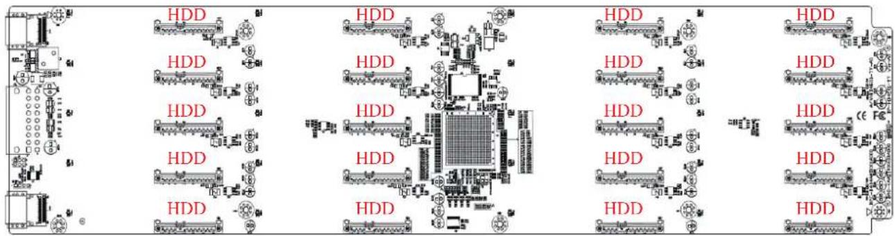
text_image
HDD HDD HDD HDD HDD HDD HDD HDD HDD HDD HDD HDD HDD HDD HDD HDD HDD HDD HDD HDD HDD HDD HDD HDD HDD HDD HDD HDD HDD HDD HDD HDD HDD HDD C F CBOTTOM
text_image
Circuit diagram with labeled components and connections, showing various circuit elements and connectionsChapter 3 Hardware Instruction
3.1.2 Connector Location
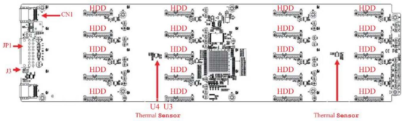
Connector Location
text_image
CN1 HDD HDD HDD HDD HDD HDD HDD HDD HDD HDD HDD HDD HDD HDD HDD HDD HDD HDD HDD HDD HDD HDD HDD HDD HDD HDD HDD HDD HDD HDD HDD HDD HDD HDD U4 U3 Thermal Sensor Thermal Sensor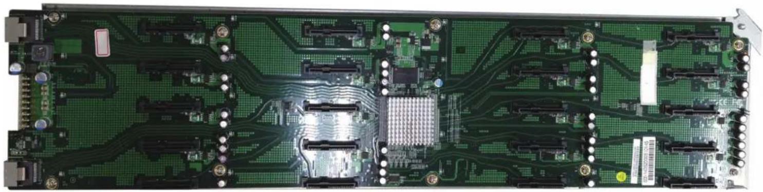
natural_image
Back view of a green printed circuit board with multiple microphones and connectors (no visible text or symbols)Chapter 3 Hardware Instruction
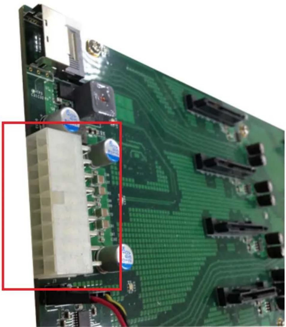
3.1.3 Power Connector
Power Connector
natural_image
Close-up of a green printed circuit board with visible components and wiring (no readable text or symbols)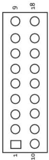
text_image
9 18 1 10| Pin | Description | Pin | Description |
| 9 | GND | 18 | +5V |
| 8 | GND | 17 | +5V |
| 7 | GND | 16 | +5V |
| 6 | GND | 15 | +5V |
| 5 | GND | 14 | +12V |
| 4 | GND | 13 | +12V |
| 3 | GND | 12 | +12V |
| 2 | GND | 11 | +12V |
| 1 | GND | 10 | +12V |
Chapter 3 Hardware Instruction
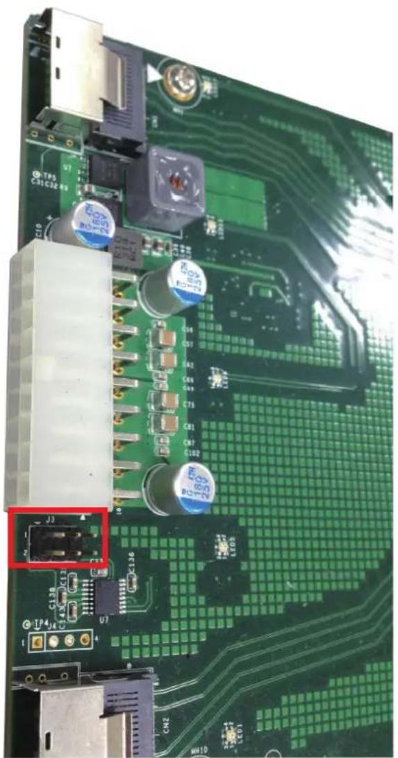
3.1.4 Console for Expander
natural_image
Close-up of a green printed circuit board with electronic components and connectors (no readable text or symbols)Console for Expander - JEXP_UART
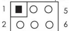
| Pin | Description | Pin | Description |
| 2 | SMART_TXD | 1 | DEBUG_RXD |
| 4 | GND | 3 | GND |
| 6 | SMART_TXD | 5 | DEBUG_RXD |
Chapter 3 Hardware Instruction
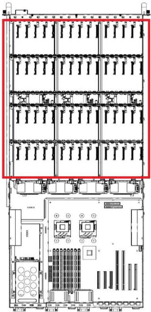
3.1.5 Drive Slot Map
natural_image
Technical line drawing of a server rack with multiple racks and internal components (no text or labels)| HBA card | ||||||||||||||
| 0 | 1 | 2 | 3 | 4 | 5 | 6 | 7 | 8 | 9 | 10 | 11 | 12 | 13 | 14 |
| 15 | 16 | 17 | 18 | 19 | 20 | 21 | 22 | 23 | 24 | 25 | 26 | 27 | 28 | 29 |
| 30 | 31 | 32 | 33 | 34 | 35 | 36 | 37 | 38 | 39 | 40 | 41 | 42 | 43 | 44 |
| 45 | 46 | 47 | 48 | 49 | 50 | 51 | 52 | 53 | 54 | 55 | 56 | 57 | 58 | 59 |
| MegaRaid card | ||||||||||||||
| 1 | 2 | 3 | 4 | 5 | 6 | 7 | 8 | 9 | 10 | 11 | 12 | 13 | 14 | 15 |
| 16 | 17 | 18 | 19 | 20 | 21 | 22 | 23 | 24 | 25 | 26 | 27 | 28 | 29 | 30 |
| 31 | 32 | 33 | 34 | 35 | 36 | 37 | 38 | 39 | 40 | 41 | 42 | 43 | 44 | 45 |
| 46 | 47 | 48 | 49 | 50 | 51 | 52 | 53 | 54 | 55 | 56 | 57 | 58 | 59 | 60 |
RSC-4H User's Manual
Chapter 4. HDD Blackplane Instruction
4.1 Expender firmware update through smart console port
4.1.1 Update Expander firmware revision
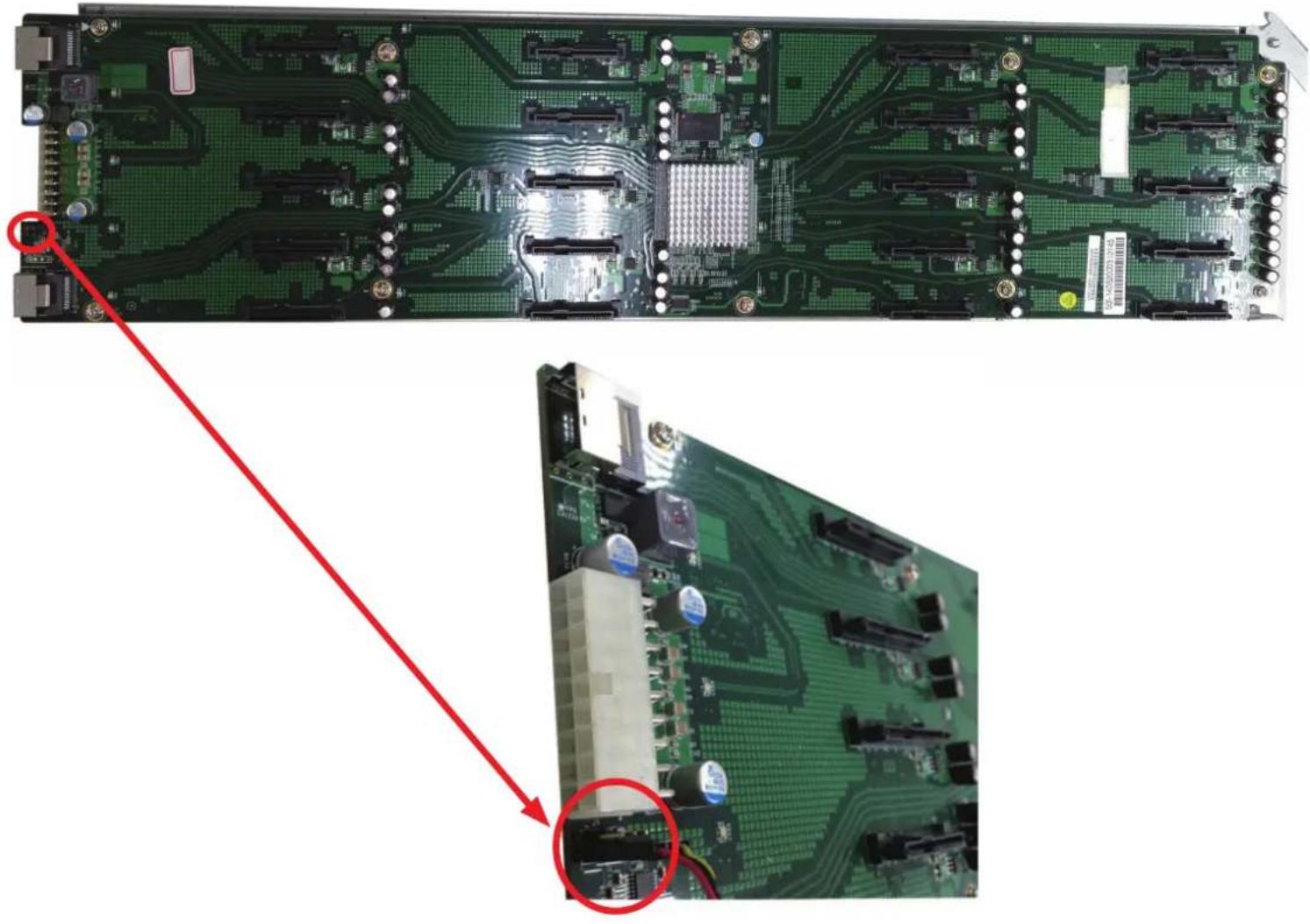
Step 1: Set up RSC-4H console serial cable. Insert console serial cable into console port shown below also the other side inert serial port into motherboard.
YOU CAN FIND OUT CONSOLE SERIAL CABLE IN THE PACKAGE BOX.
natural_image
Close-up of a green printed circuit board with visible traces and components, showing a red arrow pointing to a detail (no text or symbols present)Chapter 4 HDD Blackplane Instruction
Step 2: Set up RSC-4H RS232 connection Set up RS232 connection application into your RSC-4H as shown in the example process below.
For example:
OS: Microsoft Windows
RS232 connection application: Hyperterminal
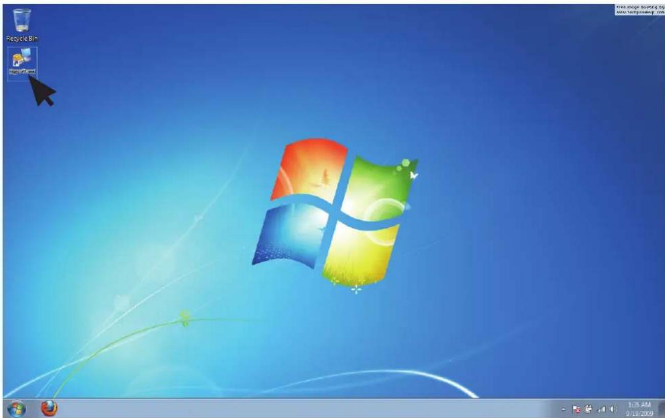
Step 2: Install HyperTrm.exe
text_image
Recycle Bin Super-Form 12:5 AM 9:19/2009Chapter 4 HDD Blackplane Instruction
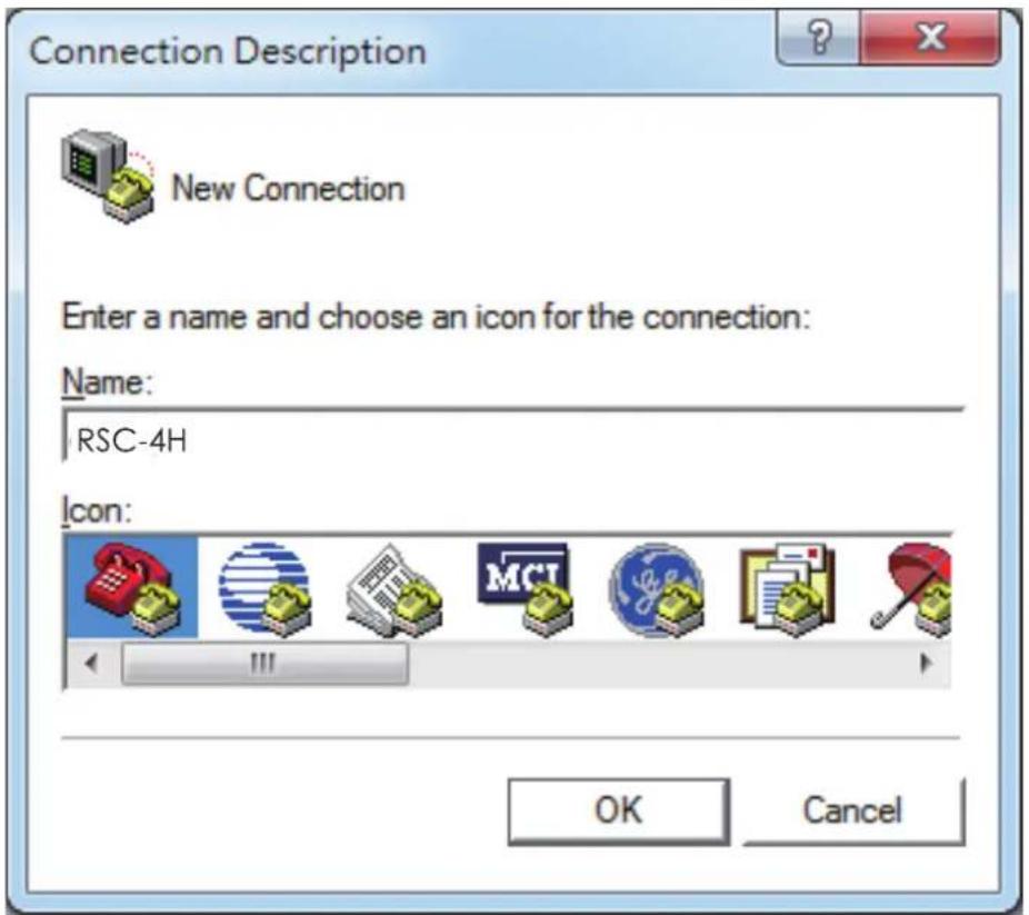
Step 3: Enter a new name for the icon in the field below and click OK.
text_image
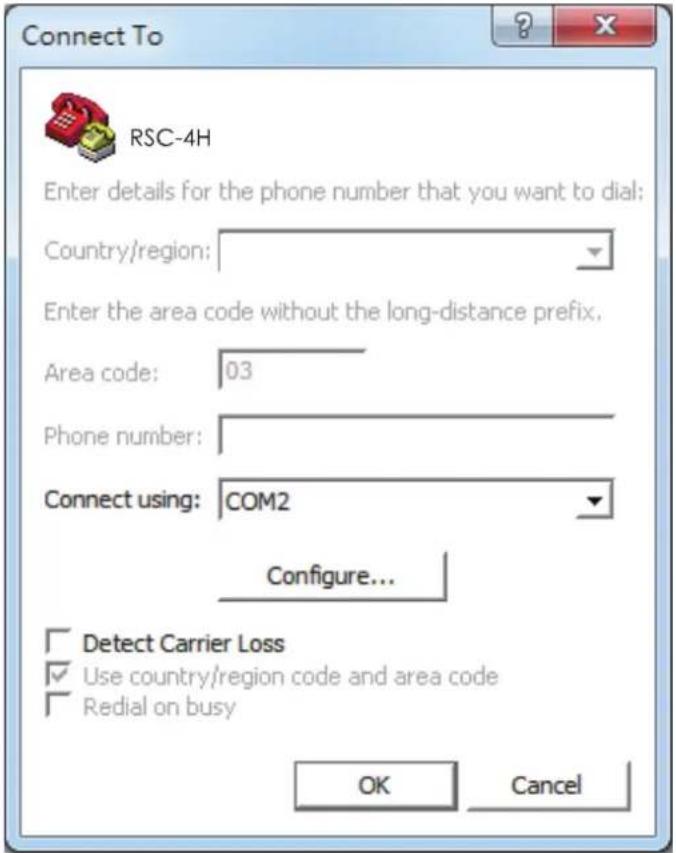
Connection Description New Connection Enter a name and choose an icon for the connection: Name: RSC-4H Icon: OK CancelStep 4: Connecting by using selecting an option in the drop down menu circled in red below (we selected COM2 in this example) and click OK.
text_image
Connect To RSC-4H Enter details for the phone number that you want to dial: Country/region: Enter the area code without the long-distance prefix. Area code: 03 Phone number: Connect using: COM2 Configure... Detect Carrier Loss Use country/region code and area code Redial on busy OK CancelRSC-4H User's Manual
Chapter 4 HDD Blackplane Instruction
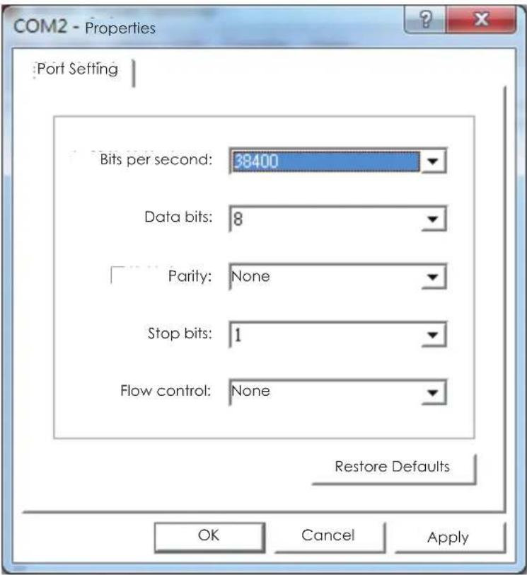
Step 5: For "Bits per second", select 38400. For "Flow control", select: None. Click OK when you have finished your selections.
text_image
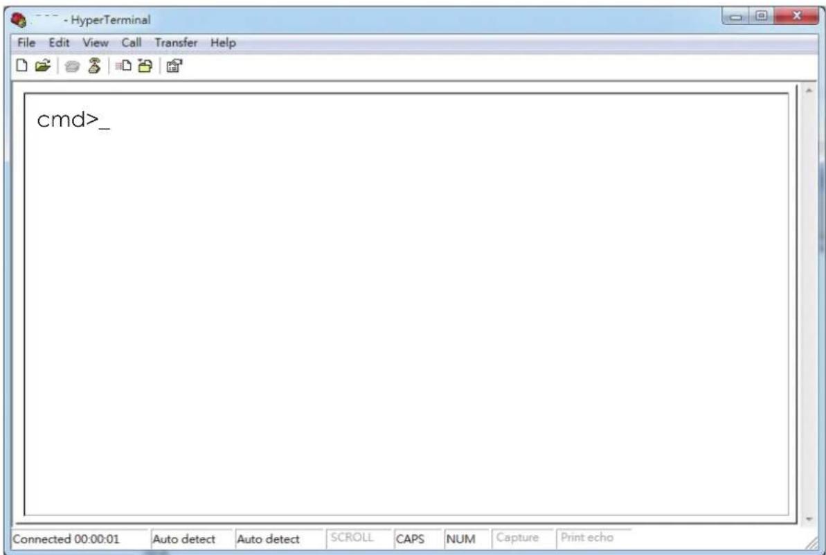
COM2 - Properties Port Setting Bits per second: 38400 Data bits: 8 Parity: None Stop bits: 1 Flow control: None Restore Defaults OK Cancel ApplyStep 6 : Set up is complete. The diagram below depicts what screen should displayed.
text_image
cmd>_RSC-4H User's Manual
Chapter 4 HDD Blackplane Instruction
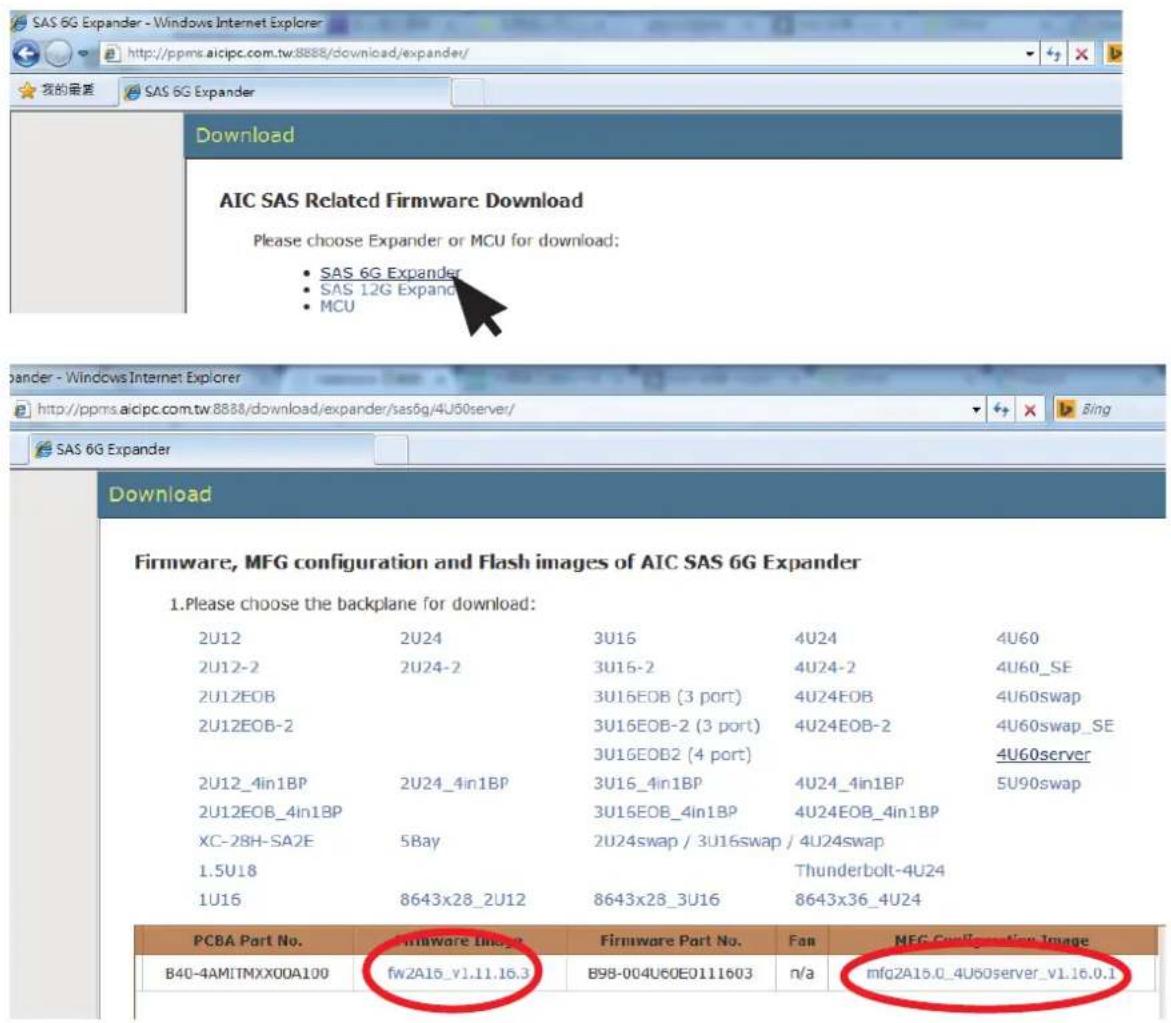
Step 7: To get firmware image & MFG Configuration Image version information from "AIC SAS Related Firmware Downloadne" website. http://ppms.aicipc.com.tw:8888/download/expander/
text_image
SAS 6G Expander - Windows Internet Explorer http://ppms.aicipc.com.tw:8888/download/expander/ 我的最新 SAS 6G Expander Download AIC SAS Related Firmware Download Please choose Expander or MCU for download: • SAS 6G Expander • SAS 12G Expand • MCU bander - Windows Internet Explorer http://ppms.aicipc.com.tw:8888/download/expander/sas6g/4U50server/ SAS 6G Expander Download Firmware, MFG configuration and Flash images of AIC SAS 6G Expander 1.Please choose the backplane for download: 2U12 2U24 3U16 4U24 4U60 2U12-2 2U24-2 3U16-2 4U24-2 4U60_SE 2U12EOB 3U16EOB (3 port) 4U24EOB 4U60swap 2U12EOB-2 3U16EOB-2 (3 port) 4U24EOB-2 4U60swap_SE 3U16EOB2 (4 port) 4U60server 2U12_4in1BP 2U24_4in1BP 3U16_4in1BP 4U24_4in1BP 5U90swap 2U12EOB_4in1BP 3U16EOB_4in1BP 4U24EOB_4in1BP XC-28H-SA2E 5Bay 2U24swap / 3U16swap / 4U24swap 1.5U18 Thunderbolt-4U24 1U16 8643x28_2U12 8643x28_3U16 8643x36_4U24 PCBA Part No. Firmware Image.Firmware Part No.Fan NFG Configuration Image B40-4AMITMXX00A100 fw2A15_v1.11.16.3 B98-004U60E0111603 n/a mfg2A15.0_4U60server_v1.16.0.1Chapter 4 HDD Blackplane Instruction
Step 8:
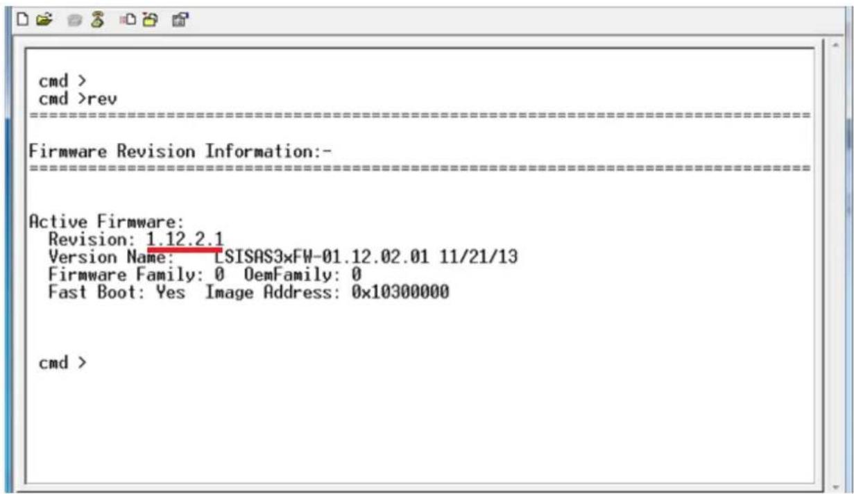
Comand line for show current firmware revision.
cmd>rev
text_image
cmd > cmd >rev Firmware Revision Information:- Active Firmware: Revision: 1.12.2.1 Version Name: LSISAS3xFW-01.12.02.01 11/21/13 Firmware Family: 0 OemFamily: 0 Fast Boot: Yes Image Address: 0x10300000 cmd >Chapter 4 HDD Blackplane Instruction
Step 9:
Start to update expander firmware
cmd>fdl 0 0_
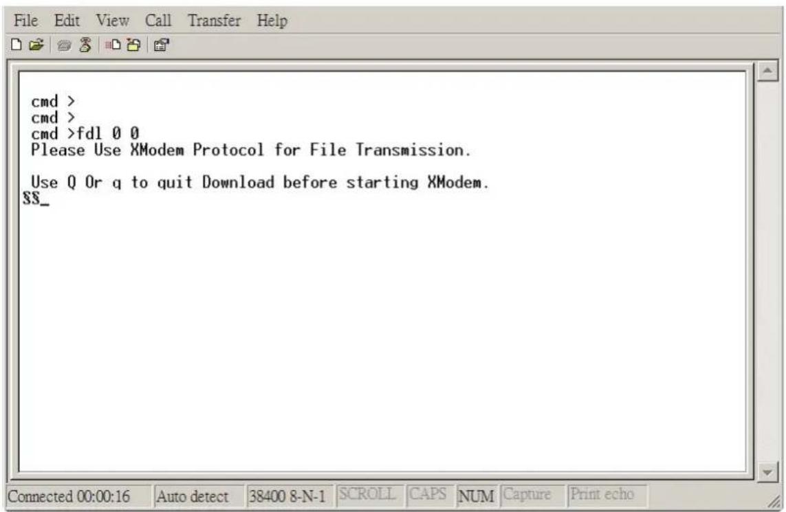
text_image
cmd > cmd > cmd >fd1 0 0 Please Use XModem Protocol for File Transmission. Use Q Or q to quit Download before starting XModem. ss_Step 10:
Select the tool bar "Transfer" -> "Send File".
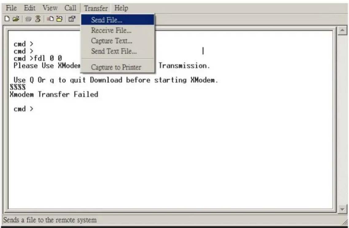
text_image
cmd > cmd > cmd >fdl 0 0 Please Use XModem Use Q Or q to quit Download before starting XModem. Xmodem Transfer Failed cmd > Send File... Receive File... Capture Text... Send Text File... Capture to Printer Transmission. Sends a file to the remote systemChapter 4 HDD Blackplane Instruction
Step 11:
- Choose new firmware path file "fw 2A16_v1.11.16.3".
- Protocol have to choose "Xmodem".
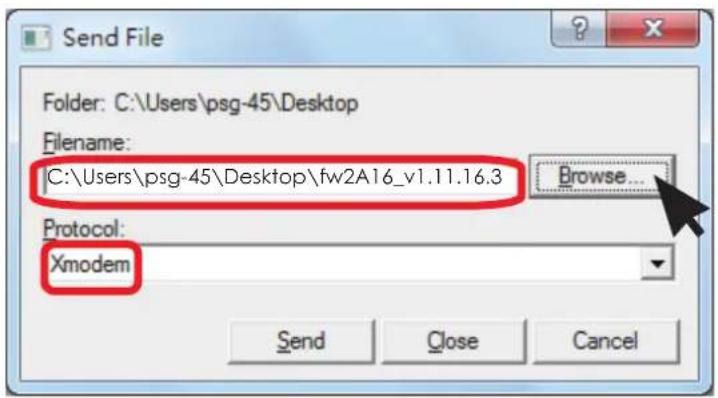
text_image
Send File Folder: C:\Users\psg-45\Desktop Filename: C:\Users\psg-45\Desktop\fw2A16_v1.11.16.3 Browse... Protocol: Xmodem Send Close CancelStep 12:
Firmware download complete
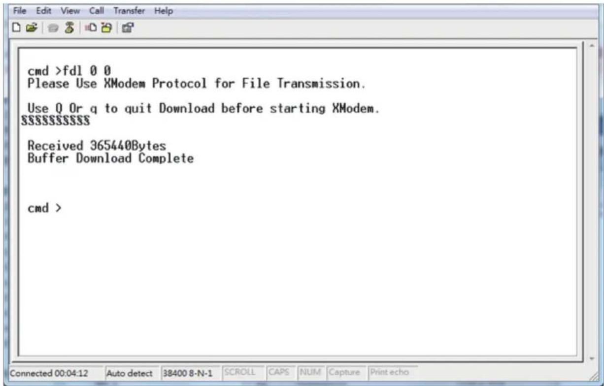
text_image
cmd >fd1 0 0 Please Use XModem Protocol for File Transmission. Use Q Or q to quit Download before starting XModem. $$$$$$$$ Received 365440Bytes Buffer Download Complete cmd >Chapter 4 HDD Blackplane Instruction
Step 13:
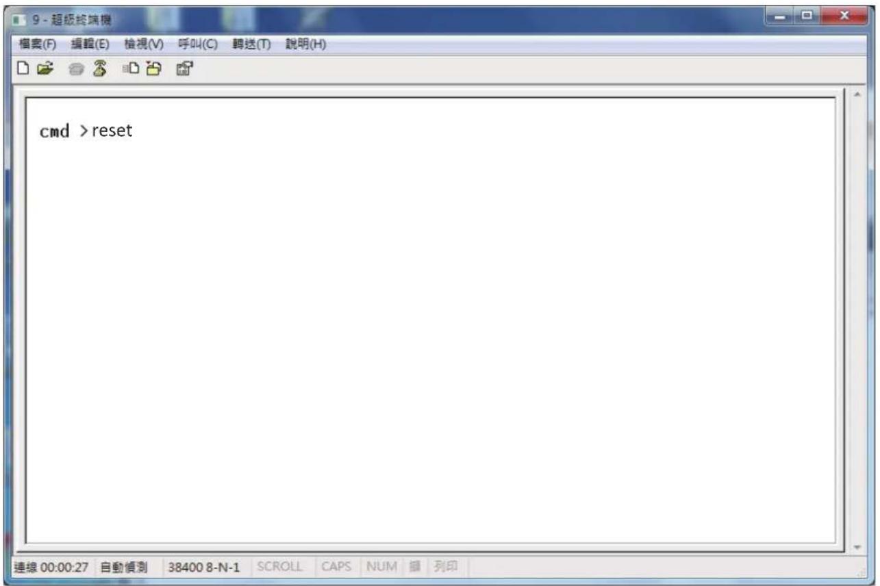
Reset computer for success update firmware.
cmd>reset
Chapter 4 HDD Blackplane Instruction
4.1.2 Update expander configuration MFG
Step 1:
Comand line for show current configuration MFG cmd> showmfg
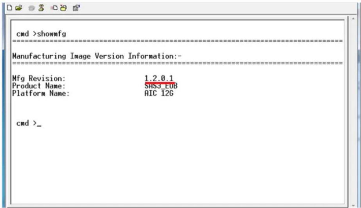
text_image
cmd >showmfg Manufacturing Image Version Information:- Mfg Revision: 1.2.0.1 Product Name: SHSJ_EOB Platform Name: AIC 12G cmd >_Chapter 4 HDD Blackplane Instruction
Step 2:
Start to update expander configuration MFG
cmd>fdl 83 0_
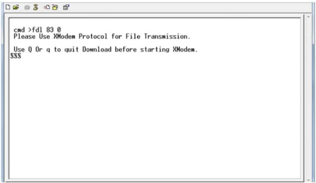
text_image
cmd >fdl 83 0 Please Use XModem Protocol for File Transmission. Use Q Or q to quit Download before starting XModem. $$$Step 3:
Select the tool bar "Transfer" -> "Send File".
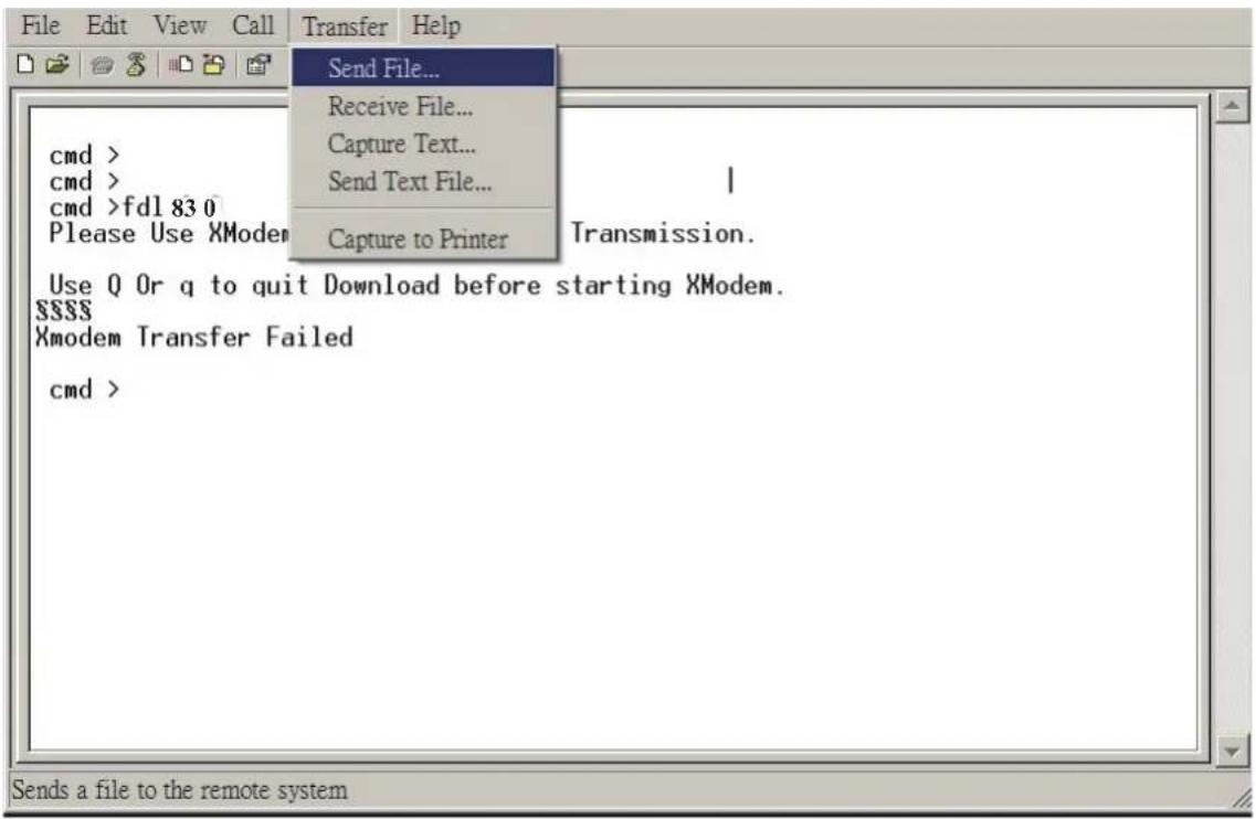
text_image
Send File... Receive File... Capture Text... Send Text File... Capture to Printer Transmission. Use Q Or q to quit Download before starting XModem. Xmodem Transfer Failed cmd >RSC-4H User's Manual
Chapter 4 HDD Blackplane Instruction
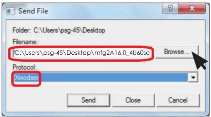
Step 4:
- Choose new MFG path file "mfg2A16.0_4U60server_v1.16.0.1".
- Protocol have to choose "Xmodem".
text_image
Send File Folder: C:\Users\psg-45\Desktop Filename: C:\Users\psg-45\Desktop\mfg2A16.0_4U60se Browse... Protocol: Xmodem Send Close CancelStep 5:
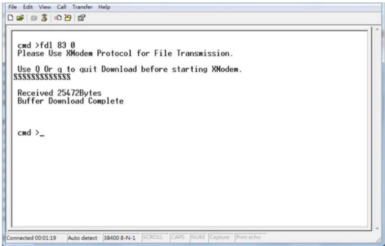
MFG download complete.
text_image
cmd >fdl 83 0 Please Use XModem Protocol for File Transmission. Use Q Or q to quit Download before starting XModem. $$$$$$$$$$$ Received 25472Bytes Buffer Download Complete cmd >_Chapter 4 HDD Blackplane Instruction
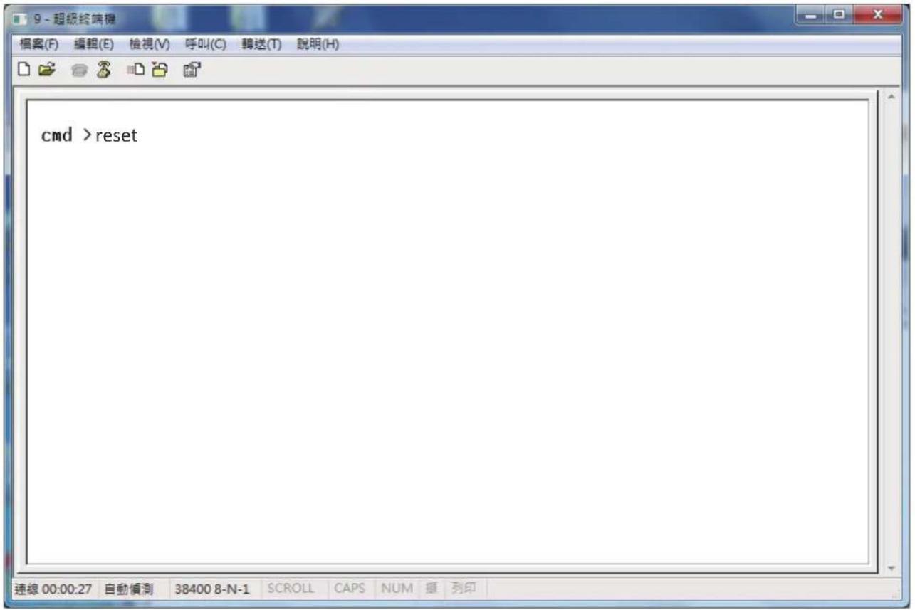
Step 6:
Reset computer for success update MFG.
cmd>reset
4.2 Update the expander firmware through in-band.
FOR EXAMPLE
Step 1:
Download and install SG3_utils.exe which compatible with Linux OS.
From website http://sg.danny.cz/sg/sg3_utils.html
website
Reference version sg3 utils-1.40.tgz
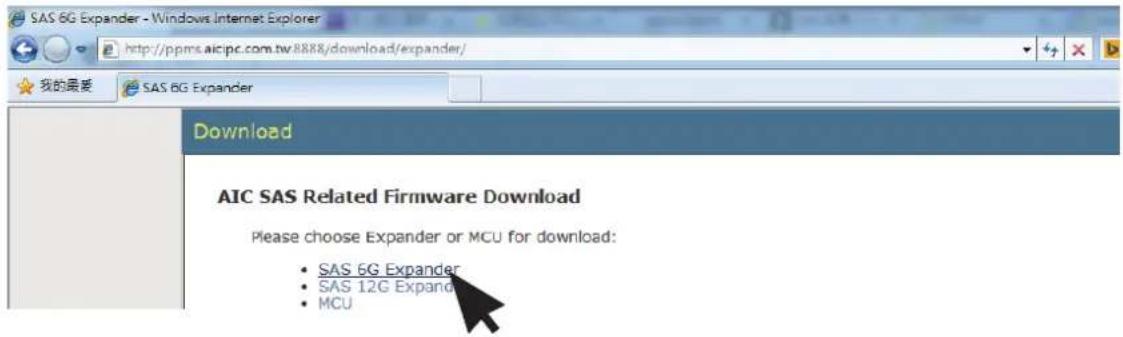
Step 2:
To get firmware image & MFG Configuration Image version information from "AIC SAS Related Firmware Downloadne" website.
http://ppms.aicipc.com.tw:8888/download/expander/
text_image
SAS 6G Expander - Windows Internet Explorer http://ppms.aicipc.com.tw/8888/download/expander/ 我的最爱 SAS 6G Expander Download AIC SAS Related Firmware Download Please choose Expander or MCU for download: • SAS 6G Expander • SAS 12G Expander • MCU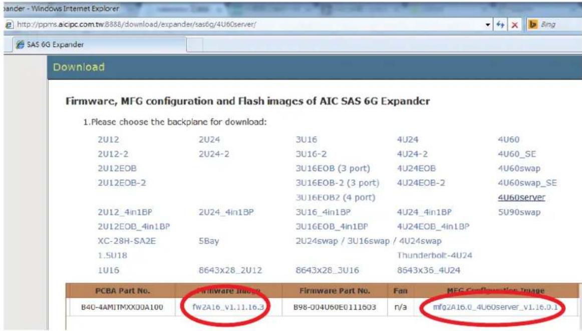
text_image
Firmware, MFG configuration and Flash images of AIC SAS 6G Expander 1.Please choose the backplane for download: 2U12 2U24 3U16 4U24 4U60 2U12-2 2U24-2 3U16-2 4U24-2 4U60_SE 2U12EOB 3U16EOB (3 port) 4U24EOB 4U60swap 2U12EOB-2 3U16EOB-2 (3 port) 4U24EOB-2 4U60swap_SE 3U16EOB2 (4 port) 4U60server 2U12_4in1BP 2U24_4in1BP 3U16_4in1BP 4U24_4in1BP 5U90swap 2U12EOB_4in1BP 3U16EOB_4in1BP 4U24EOB_4in1BP XC-28H-SA2E 5Bay 2U24swap / 3U16swap / 4U24swap 1.5U18 Thunderbolt-4U24 1U16 8643x28_2U12 8643x28_3U16 8643x36_4U24 PCBA Part No. Firmware Part No. Fan MFG Configuration Image B40-4AMITMXX00A100 fW2A16_V1.11.16.3 B98-004U60E0111603 n/a mfQZA16.0_4U60server_v1.16.0.1Chapter 4 HDD Blackplane Instruction
Step 3:
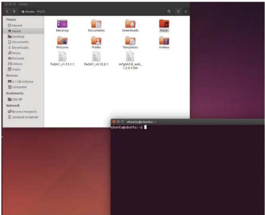
Execute terminal under the same new firmware folder.
example: Setting a new firmware folder on "Home" page. Open Terminal by click to the right button of mouse in the same window "Home".
text_image
Home Places Recent Home Desktop Documents Downloads Music Pictures Videos Trash Devices 2.1 GB Volume Computer Bookmarks 12G BP Network Browse a Network Connect to Server Desktop Documents Downloads Music Pictures Public Templates Videos fw2A1_v1.1.1.1 fw3A1_v1.12.2.1 mfg3A1.0_eob_ 1.2.0.1.bin ubuntu@ubuntu:- ubuntu@ubuntu:~$Step 4:
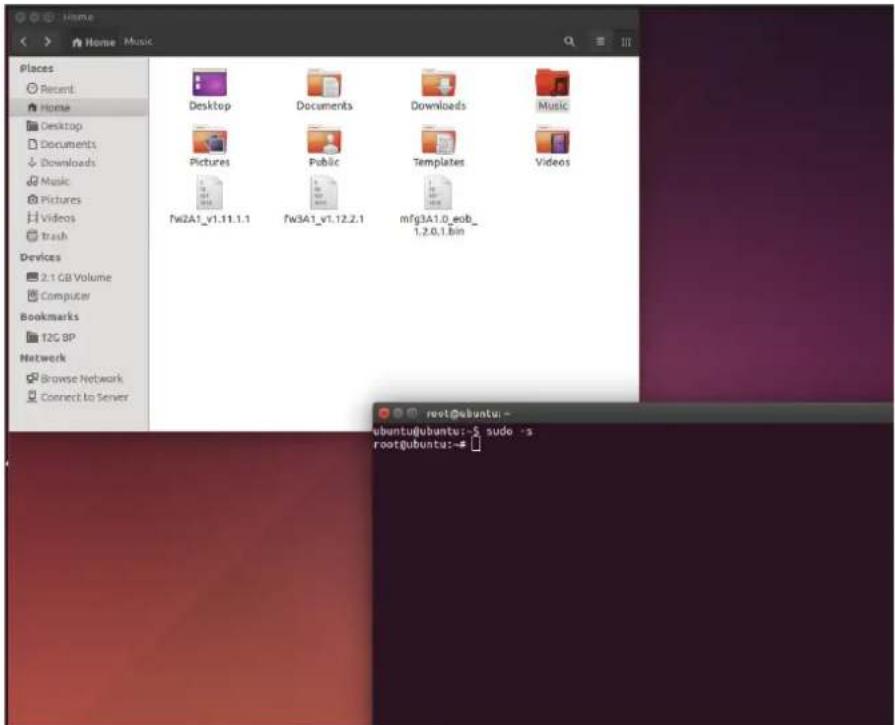
Typing "sudo -s" to into administrator mode.
text_image
Places Recent Home Desktop Documents Downloads Music Pictures Videos Trash Devices 2.1 GB Volume Computer Bookmarks T2G BP Network Browse Network Connect to Server Desktop Documents Downloads Music Pictures Public Templates Videos fw2A1_v1.11.1.1 fw3A1_v1.12.2.1 mfg3A1.0_ecob_ 1,2,6,1.bin root@ubuntu:- ubuntu@ubuntu:~$ sudo ~s root@ubuntu:~#RSC-4H User's Manual
Chapter 4 HDD Blackplane Instruction
Step 5:
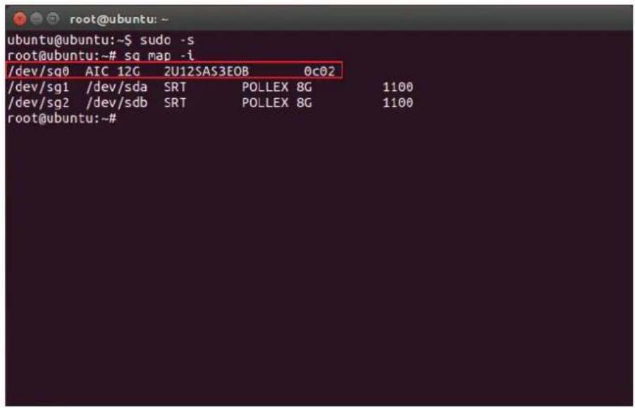
Find expander location.
\$ sg_map -i
text_image
/dev/sq0 AIC 12G 2U12SAS3EOB 0c02 /dev/sg1 /dev/sda SRT POLLEX 8G 1100 /dev/sg2 /dev/sdb SRT POLLEX 8G 1100 root@ubuntu:~#Step 6:
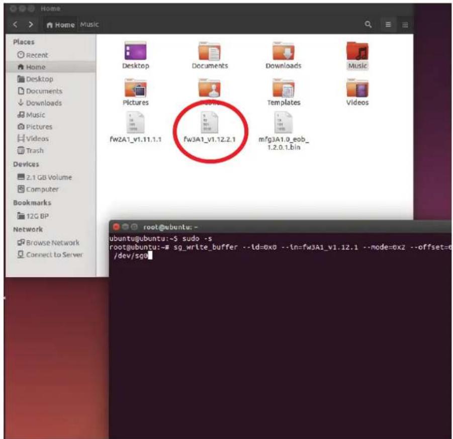
Update Expander firmware
\$ sg_write_buffer --id=0x0 --in=fw3A1_v1.12.2.1 --mode=0x2 --offset=0 / dev/sg0
text_image
Places Recent Home Desktop Documents Downloads Music Pictures fw2A1_v1.11.1.1 fw3A1_v1.12.2.1 Templates Videos 2.1 GB Volume Computer Bookmarks 12G BP Network Browse Network Connect to Server root@ubuntu: - ubuntu@ubuntu:~s sudo -s root@ubuntu:~# sg_write_buffer --id=0x0 --in=fw3A1_v1.12.1 --mode=0x2 --offset=0 /dev/sg0RSC-4H User's Manual
Chapter 4 HDD Blackplane Instruction
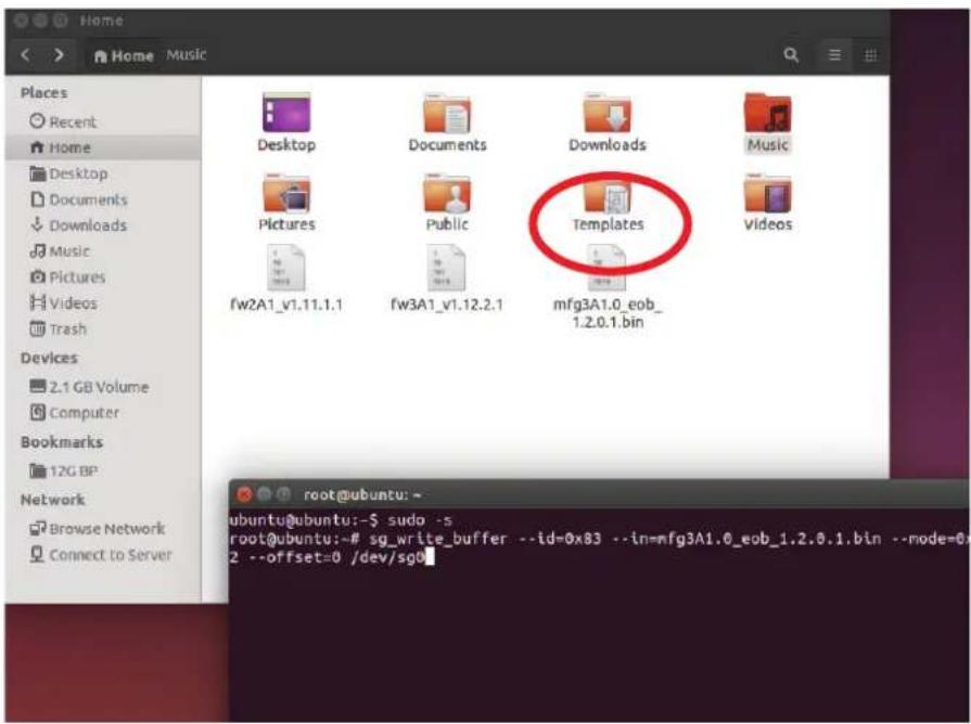
Step 7:
Update Expander MFG
\$ sg_write_buffer --id=0x83 --in=mfg3A1.0_eob_1.2.0.1.bin --mode=0x2 --offset=0 /dev/sg0
text_image
Places Recent Home Desktop Documents Downloads Music Pictures Public Templates fw2A1_v1.11.1.1 fw3A1_v1.12.2.1 mfg3A1.0_eob_ 1.2.0.1.bin Devices 2.1 GB Volume Computer Bookmarks 12G BP Network Browse Network Connect to Server root@ubuntu: - ubuntu@ubuntu:~$ sudo -s root@ubuntu:~# sg_write_buffer --id=0x83 --in=mfg3A1.0_eob_1.2.0.1.bin --mode=0x83 --offset=0 /dev/sg0Step 8:
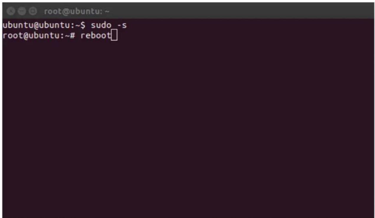
Reboot computer for success update firmware & MFG. root@ubuntu:\~# reboot
text_image
ubuntu@ubuntu:~$ sudo -s root@ubuntu:~# rebootRSC-4H User's Manual
4.3 12G expander EDFB setting
Step 1:
For Install HyperTerminal.exe refer to section 4.1
Step 2 :
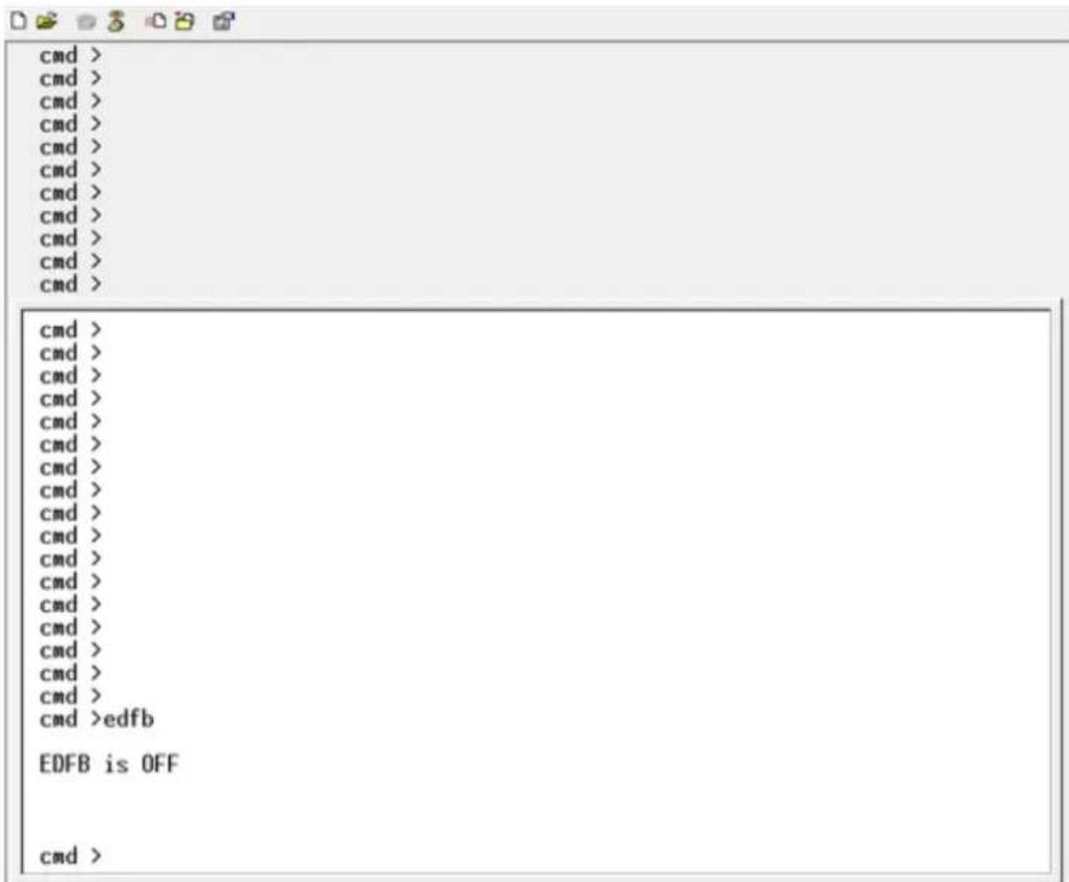
Get EDFB status
cmd> edfb
text_image
cmd > cmd > cmd > cmd > cmd > cmd > cmd > cmd > cmd > cmd > cmd > cmd > cmd > cmd > cmd > cmd > cmd > cmd > cmd > cmd > cmd > cmd > cmd > cmd > cmd > cmd > cmd > cmd > cmd > cmd > cmd > cmd > cmd > cmd > cmd > cmd > cmd > cmd > cmd > cmd > cmd > cmd > cmd > cmd > cmd > cmd > cmd > cmd > cmd > cmd > cmd >edfb EDFB is OFF cmd >Chapter 4 HDD Blackplane Instruction
Step 3:
Change EDFB setting
Enable EDFB function
cmd>edfb on
Disable EDFB function
cmd>edfb off

text_image
cmd > cmd > cmd > cmd > cmd > cmd > cmd > cmd > cmd > cmd > cmd > cmd > cmd > cmd > cmd > cmd > cmd > cmd > cmd > cmd > cmd > cmd > cmd > cmd > cmd > cmd > cmd > cmd > cmd > cmd > cmd > cmd > cmd > cmd > cmd > cmd > cmd > cmd > cmd > cmd > cmd > cmd > cmd > cmd > cmd > cmd > cmd > cmd > cmd > cmd > cmd >edfb EDFB is OFF cmd >edfb on Succeeded to set EDFB cmd >edfb off EDFB is OFF4.4 Slot HDD power setting
(Only for system cooling Fan controlled by expander.)
Step 1:
For Install sg3.exe tool and get new firmware from website refer to section 4.2
Step 2:
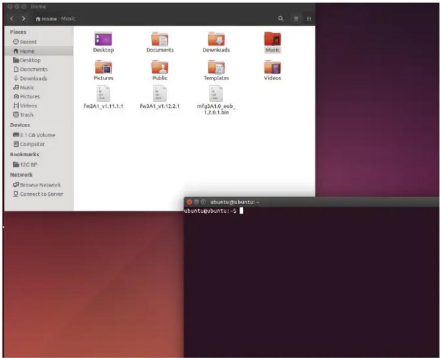
Execute terminal under the same new firmware folder.
example: Setting a new firmware folder on "Home" page. Open Terminal by click to the right button of mouse in the same window "Home".
text_image
Home Places Recent Home Desktop Documents Downloads Music Pictures Public Templates Videos fw2A1_v1.11.1.1 fw3A1_v1.12.2.1 mfg3A1.6_eob_ 1.2.0.1.bin Devices 2.1 GB Volume Computer Bookmarks 12C BP Network Browse Network Connect to Server ubuntu@ubuntu: - ubuntu@ubuntu: -$Chapter 4 HDD Blackplane Instruction
Step 3:
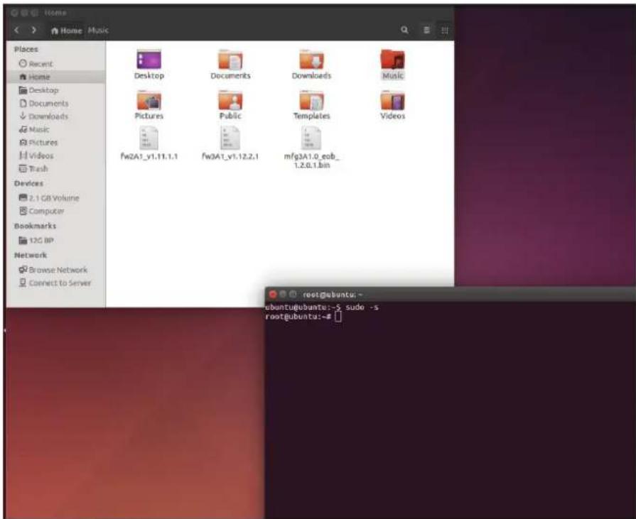
Typing "sudo -s" to into administrator mode.
text_image
Places Recent Home Desktop Documents Downloads Music Pictures Pictures Videos Trash Devices 2.1 GB Volume Computer Bookmarks 12C BP Network Browse Network Connect to Server Desktop Documents Downloads Music Pictures Public Templates Videos fw2A1_v1.11.1.1 fw3A1_v1.12.2.1 mfg3A1.0_eob_ 1.2.6.1.bin root@ubuntu:~ ubuntu@ubuntu:-$ sudo -s root@ubuntu:-#Step 4:
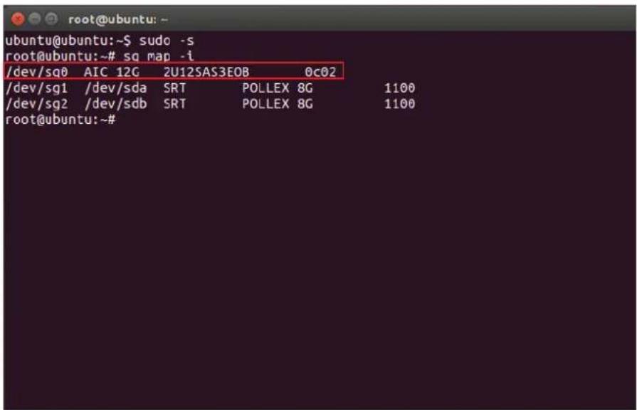
Find expander location.
\$ sg_map -i
text_image
ubuntu@ubuntu:~$ sudo -s root@ubuntu:~# sq map -i /dev/sq0 AIC 12G 2U12SAS3EOB 0c02 /dev/sg1 /dev/sda SRT POLLEX 8G 1100 /dev/sg2 /dev/sdb SRT POLLEX 8G 1100 root@ubuntu:~#Chapter 4 HDD Blackplane Instruction
Step 5:
For example:
If would like to turn the Disk004 power off under the HBA card. Need to check Disk004 power status.
\$ sg_ses --page=7 /dev/sg0
Under HBA card the Element 3 = Disk004.
root@ubuntu:~# sg_ses --page=7 /dev/sg0
AIC 12G 2U12SAS3E08 0c02
Primary enclosure logical identifier (hex): 500605b0000272bf
Element Descriptor In diagnostic page:
generation code: 0x0
element descriptor list (grouped by type):
    Element type: Array device slot, subenclosure id: 0 [ti=0]
    Overall descriptor: ArrayDevicesInSubEnclsr0
    Element 0 descriptor: Disk001
    Element 1 descriptor: Disk002
    Element 2 descriptor: Disk003
    Element 3 descriptor: Disk004
    Element 4 descriptor: Disk005
    Element 5 descriptor: Disk006
    Element 6 descriptor: Disk007
    Element 7 descriptor: Disk008
    Element 8 descriptor: Disk009
    Element 9 descriptor: Disk010
    Element 10 descriptor: Disk011
    Element 11 descriptor: Disk012
    Element type: Temperature sensor, subenclosure id: 0 [ti=1]
    Overall descriptor: TempSensorsInSubEnclsr0
    Element 0 descriptor: TempSense01
    Element 1 descriptor: TempSense02
root@ubuntu: ~
Element 5 descriptor: Disk006
Element 6 descriptor: Disk007
Element 7 descriptor: Disk008
Element 8 descriptor: Disk009
Element 9 descriptor: Disk010
Element 10 descriptor: Disk011
Element 11 descriptor: Disk012
Element type: Temperature sensor, subenclosure id: 0 [ti=1]
Overall descriptor: TempSensorsInSubEnclsr0
Element 0 descriptor: TempSense01
Element 1 descriptor: TempSense02
Element type: Voltage sensor, subenclosure id: 0 [ti=2]
Overall descriptor: VoltageSensorsInSubEnclsr0
Element 0 descriptor: VoltageSense01
Element 1 descriptor: VoltageSense02
Element type: Enclosure, subenclosure id: 0 [ti=3]
Overall descriptor: EnclosureElementInSubEnclsr0
Element 0 descriptor: EnclosureElement01
Element type: Power supply, subenclosure id: 0 [ti=4]
Overall descriptor: PowerSupplyInSubEnclsr0
Element 0 descriptor: PowerSupply01
Element 1 descriptor: DiskPowerSupply
Chapter 4 HDD Blackplane Instruction
Step 6:
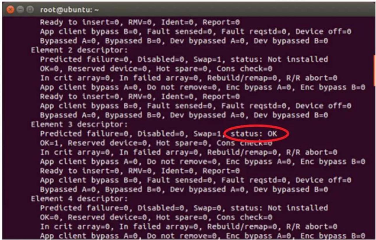
To check Disk004 (element 3) power status is ok \$ sg_ses --page=2 /dev/sg0

text_image
ubuntu@ubuntu:~$ sudo -s root@ubuntu:~# sg_map -i /dev/sg0 AIC 12G 2U12SAS3EOB 0c02 /dev/sg1 /dev/sda SRT POLLEX 8G 1100 root@ubuntu:~# sg_ses --page=2 /dev/sg0Status shows below:
The status of Element 3 is OK.
text_image
root@ubuntu: ~ Ready to insert=0, RMV=0, Ident=0, Report=0 App client bypass B=0, Fault sensed=0, Fault reqstd=0, Device off=0 Bypassed A=0, Bypassed B=0, Dev bypassed A=0, Dev bypassed B=0 Element 2 descriptor: Predicted failure=0, Disabled=0, Swap=1, status: Not installed OK=0, Reserved device=0, Hot spare=0, Cons check=0 In crit array=0, In failed array=0, Rebuild/remap=0, R/R abort=0 App client bypass A=0, Do not remove=0, Enc bypass A=0, Enc bypass B=0 Ready to insert=0, RMV=0, Ident=0, Report=0 App client bypass B=0, Fault sensed=0, Fault reqstd=0, Device off=0 Bypassed A=0, Bypassed B=0, Dev bypassed A=0, Dev bypassed B=0 Element 3 descriptor: Predicted failure=0, Disabled=0, Swap=1, status: OK OK=1, Reserved device=0, Hot spare=0, Cons check=0 In crit array=0, In failed array=0, Rebuild/remap=0, R/R abort=0 App client bypass A=0, Do not remove=0, Enc bypass A=0, Enc bypass B=0 Ready to insert=0, RMV=0, Ident=0, Report=0 App client bypass B=0, Fault sensed=0, Fault requstd=0, Device off=0 Bypassed A=0, Bypassed B=0, Dev bypassed A=0, Dev bypassed B=0 Element 4 descriptor: Predicted failure=0, Disabled=0, Swap=0, status: Not installed OK=0, Reserved device=0, Hot spare=0, Cons check=0 In crit array=0, In failed array=0, Rebuild/remap=0, R/R abort=0 App client bypass A=0, Do not remove=0, Enc bypass A=0, Enc bypass B=0Chapter 4 HDD Blackplane Instruction
Step 7:
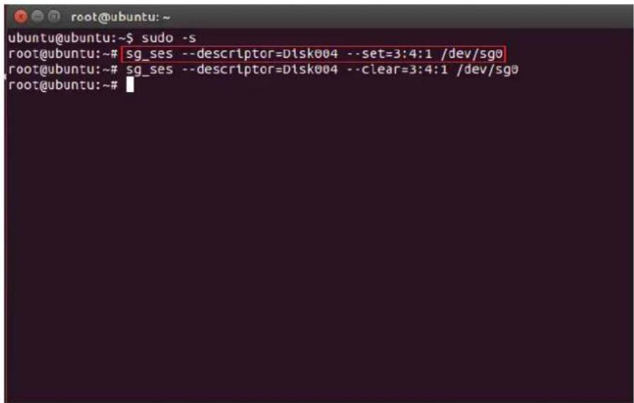
Turn off a HDD power
\$ sg_ses --descriptor=Disk004 --set=3:4:1 /dev/sg0
text_image
ubuntu@ubuntu:~$ sudo -s root@ubuntu:~# sg_ses --descriptor=Disk004 --set=3:4:1 /dev/sg0 root@ubuntu:~# sg_ses --descriptor=Disk004 --clear=3:4:1 /dev/sg0 root@ubuntu:~#Step 8:
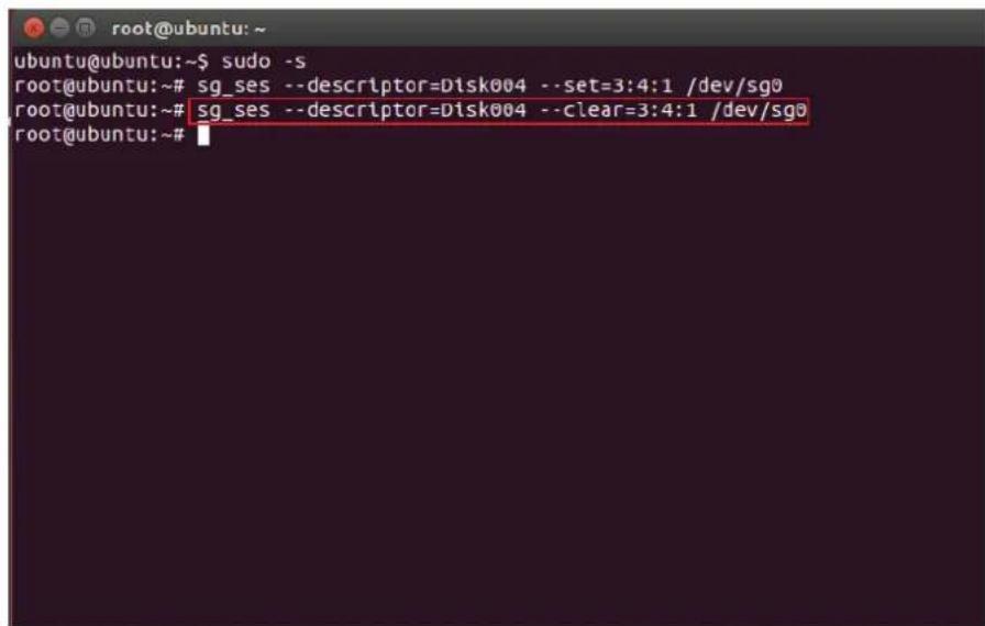
Turn on a HDD power
\$ sg_ses --descriptor=Disk004 --clear=3:4:1 /dev/sg0
text_image
ubuntu@ubuntu:~$ sudo -s root@ubuntu:~# sg_ses --descriptor=Disk004 --set=3:4:1 /dev/sg0 root@ubuntu:~# sg_ses --descriptor=Disk004 --clear=3:4:1 /dev/sg0 root@ubuntu:~#4.5 HDD BP thermal sensor temperature setting
(Only for system cooling Fan controlled by expander.)
Step 1:
For Install HyperTerminal.exe refer to section 4.1
Step 2:
Get the current temperature settings
cmd> temperature
cmd >
cmd >temperature
Temperature in Celsius (t1=20 C, t2=50 C, warning=50 C, alarm=55 C)
cmd >
cmd >
cmd >
cmd >
cmd >
cmd >
cmd >
cmd >
cmd >
cmd >
Chapter 4 HDD Blackplane Instruction
Step 3.
For example:
Set new temperature
T1=20 C ▶ 18 C
T2=50 C ▶ 52 C
Warning threshold=50 C ▶ 48 C
Alarm threshold=55 C ▶ 54 C
The new setting will take effect after reset.
cmd> temperature 18 52 48 54
cmd>reset
cmd >
cmd >
cmd >
cmd >
cmd >
cmd >
cmd >
cmd >
cmd >
cmd >
cmd >temperature 18 52 48 54
Succeeded to update temperature
cmd >reset_
Chapter 4 HDD Blackplane Instruction
Step 4.
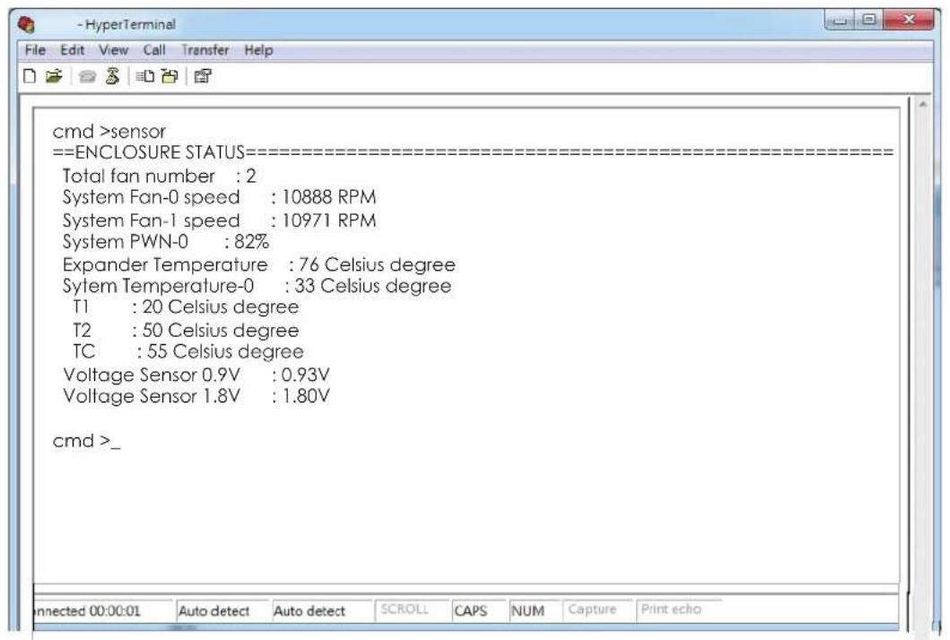
Check fan speed & temperature information.
cmd> sensor
text_image
cmd >sensor ==ENCLOSURE STATUS===================== Total fan number : 2 System Fan-0 speed : 10888 RPM System Fan-1 speed : 10971 RPM System PWN-0 : 82% Expander Temperature : 76 Celsius degree Sytem Temperature-0 : 33 Celsius degree T1 : 20 Celsius degree T2 : 50 Celsius degree TC : 55 Celsius degree Voltage Sensor 0.9V : 0.93V Voltage Sensor 1.8V : 1.80V cmd >_Chapter 5. Technical Support

text_image
AICwww.aicipc.com
• TAIWAN
Tel: +886.3.313.8386
Fax: +886.3.313.8377
Email : sales@aicipc.com.tw
- CHINA
Tel: +86.21.54961421, +86.21.54961422
Fax: Extension: 608
Email Technical Support: support@aicipc.com
• AMERICA - West coast
Tel: +1.909.895.8989
Fax: +1.909.895.8999
Email : sales@aicipc.com
• AMERICA - East coast
Tel: +1.973.884.8886
Fax: +1.973.884.4794
Email : njsales@aicipc.com
• EUROPE
Tel: +31.30.6386789
Fax: +31.30.6360638
Email:sales@aicipc.nl
Email Technical Support: support@aicipc.com