Super Cub - Remote control toy Flyzone - Free user manual and instructions
Find the device manual for free Super Cub Flyzone in PDF.


| Type of Product | Remote Control Airplane (Receiver-Ready) |
| Brand | Flyzone |
| Model | Super Cub |
| Wingspan | 48 in (1220 mm) |
| Wing Area | 354 in² (22.8 dm²) |
| Weight | 30.4 oz (860 g) |
| Wing Loading | 12.4 oz/ft² (38 g/dm²) |
| Length | 33 in (840 mm) |
| Radio Required | 4-channel transmitter and receiver |
| Motor | Brushless (included) |
| ESC | 18 Amp (included) |
| Servos | Pre-installed (4 servos) |
| Battery (Recommended) | Flyzone 1300mAh 11.1V LiPo (HCAA6310) |
| Propeller | 8.25 in diameter (included) |
| Warranty | Hobbico guarantees against defects in material and workmanship |
| Replacement Parts | Available via order numbers (see manual) |
| Maintenance | Check screws, clean after flight, inspect for damage |
| Safety Precautions | Keep propeller clear, perform range check, avoid flying near people |
| Assembly Required | Yes (landing gear, stabilizers, wing, propeller) |
Frequently Asked Questions - Super Cub Flyzone
User questions about Super Cub Flyzone
0 question about this device. Answer the ones you know or ask your own.
Ask a new question about this device
Download the instructions for your Remote control toy in PDF format for free! Find your manual Super Cub - Flyzone and take your electronic device back in hand. On this page are published all the documents necessary for the use of your device. Super Cub by Flyzone.
USER MANUAL Super Cub Flyzone
text_image
Flyzone™ how high will you soar RX-R™ RECEIVER-READYSuper Cub
INSTRUCTION MANUAL
- SPECIFICATIONS
| Wingspan: | 48 in [1220mm] |
| Wing Area: | 354 in ^2 [22.8 dm ^2 ] |
| Weight: | 30.4 oz [860 g] |
| Wing Loading: | 12.4 oz/ft ^2 [38 g/dm ^2 ] |
| Length: | 33 in [840mm] |
| Radio: | 4-channel (required) |
WARRANTY
Hobbico guarantees this kit to be free from defects in both material and workmanship at the date of purchase. This warranty does not cover any component parts damaged by use or modification. In no case shall Hobbico's liability exceed the original cost of the purchased kit. Further, Hobbico reserves the right to change or modify this warranty without notice.
In that Hobbico has no control over the final assembly or material used for final assembly, no liability shall be assumed nor accepted for any damage resulting from the use by the user of the final user-assembled product. By the act of using the user-assembled product, the user accepts all resulting liability.
If the buyer is not prepared to accept the liability associated with the use of this product, the buyer is advised to return
this kit immediately in new and unused condition to the place of purchase.
To make a warranty claim send the defective part or item to Hobby Services at the address below:
Hobby Services
3002 N. Apollo Dr. Suite 1
Champaign IL 61822 USA
Include a letter stating your name, return shipping address, as much contact information as possible (daytime telephone number, fax number, e-mail address), a detailed description of the problem and a photocopy of the purchase receipt. Upon receipt of the package the problem will be evaluated as quickly as possible.
READ THROUGH THIS MANUAL BEFORE STARTING CONSTRUCTION. IT CONTAINS IMPORTANT INSTRUCTIONS AND WARNINGS CONCERNING THE ASSEMBLY AND USE OF THIS MODEL.
TABLE OF CONTENTS
INTRODUCTION 2
SAFETY PRECAUTIONS 2
ADDITIONAL ITEMS REQUIRED ....3
Radio Control System ....3
Additional Battery and Charging System (Optional) .3
Required Assembly Tools....3
ORDERING REPLACEMENT PARTS ....3
KIT INSPECTION....4
KIT CONTENTS....4
ASSEMBLE THE MODEL ....5
Mount the Main Landing Gear ....5
Mount the Vertical and Horizontal Stabilizers.....5
Hook Up the Controls....7
Check the Control Throws 9
Increased Elevator Throw for Expert Pilots (Optional) ..10
Mount the Wing 10
FINAL PREPARATION 12
Mount the Propeller .....12
Check the C.G. (Center of Gravity) .....12
GET THE MODEL READY TO FLY 14
Identify Your Model ....14
Charge the Battery....14
FLYING THE PIPER Super CUB .....14
Find a Suitable Flying Site .....14
Know Your Frequency....14
Perform a Range Check....15
Monitor Your Flight Time....15
Take Off 15
Flying Back Cover
Landing Back Cover
After Flight .... Back Cover
INTRODUCTION
Thank you for purchasing the Piper Super Cub RxR (receiver ready). The Cub is forgiving and “friendly” enough for pilots with little experience, but also responsive enough for experienced pilots who desire a durable Piper Cub that they can “toss” around the sky.
For the latest technical updates or manual corrections to the Super Cub visit the Hobbico web site at www.hobbico.com. Open the "Airplanes" link, then select "Super Cub". If there is new technical information or changes to this model a "tech notice" box will appear in the upper left corner of the page.
AMA
If you are not already a member of the AMA, please join! The AMA is the governing body of model aviation and membership provides liability insurance coverage, protects modelers' rights and interests and is required to fly at most R/C sites.
ACADEMY OF MODEL AERONAUTICS

text_image
AMA SINCE 19365151 East Memorial Drive
Muncie, IN 47302-9252
Tele. (800) 435-9262
Fax (765) 741-0057
Or via the Internet at:
http://www.modelaircraft.org
http://www.modelaircraft.org/parkfl yer.aspx
IMPORTANT!!!
Two of the most important things you can do to preserve the radio controlled aircraft hobby are to avoid fl ying near full-scale aircraft and avoid fl ying near or over groups of people.
PROTECT YOUR MODEL, YOURSELF & OTHERS... FOLLOW THESE IMPORTANT SAFETY PRECAUTIONS
-
Your Super Cub should not be considered a toy, but rather a sophisticated, working model that functions very much like a full-size airplane. Because of its performance capabilities, the Cessna Skylane, if not assembled and operated correctly, could possibly cause injury to yourself or spectators and damage to property.
-
You must assemble the model according to the instructions. Do not alter or modify the model, as doing so may result in an unsafe or unfl yable model. In a few cases the instructions may differ slightly from the photos. In those instances the written instructions should be considered as correct.
-
If you are not an experienced pilot or have not fl own this type of model before, we recommend that you get the assistance of an experienced pilot in your R/C club for your fi rst fl ights. If you're not a member of a club, your local hobby shop has information about clubs in your area whose membership includes experienced pilots.
-
While this kit has been fl ight tested to exceed normal use, if the plane will be used for extremely high stress fl ying, such as racing, or if an engine larger than one in the recommended range is used, the modeler is responsible for taking steps to reinforce the high stress points and/or substituting hardware more suitable for the increased stress.
We, as the kit manufacturer, provide you with a top quality, thoroughly tested kit and instructions, but ultimately the quality and fl yability of your fi nished model depends on how you build it; therefore, we cannot in any way guarantee the performance of your completed model, and no representations are expressed or implied as to the performance or safety of your completed model.
ADDITIONAL ITEMS REQUIRED
Radio Control System
The Piper Super Cub comes with the servos installed, so all that is required is a 4-channel transmitter and receiver. The Tactic™ TTX404 2.4GHz spread spectrum 4-channel radio control system (TACJ0404) is included with the RTF (ready to fl y) version of the Piper Super Cub, so this same radio system is ideal for your RXR version, too.
☐ Tactic TTX404 2.4GHz 4-channel system (TACJ0404)
☐ (8) AA batteries will be required to operate the recommended transmitter (FUGP7308).
☐ A 6" [152mm] servo extension wire (HCAM2000) will also be required.
Battery and Charger
Your Piper Super Cub was designed for the Flyzone 1300mAh 11.1V LiPo battery (HCAA6310). Other batteries similar in size with the same voltage and capacity may also work, but they may not fit properly in the battery compartment or have the same kind of battery connectors. In addition to a battery, a LiPo battery charger is also required and there are several that will work (depending on your budget and requirements). A safe, economical charger is the Great Planes® 3S (3-cell/11.1V) LiPo Smart Charger (GPMM3318). The Smart Charger includes adapters to charge from a 110V wall outlet or a 12V DC outlet from a car. The Smart Charger charges at a rate of 800mA, which works out to a charge time of an hour-and-a-half (1300mAh divided by 800mA = 1.625 x 60 minutes = 97 minutes). But some pilots prefer to have several batteries and charge them faster so they can fly more. For charging up to four batteries faster (60 minutes) all at the same time, the Great Planes PolyCharge4™ DC-powered LiPo charger (GPMM3015) is recommended. But unlike the included ElectriFly charger, the PolyCharge4 does not have an internal LiPo cell balancer which is a critical component in making sure your LiPo batteries charge efficiently and evenly. So, for each LiPo battery you wish to charge simultaneously, one Great Planes Equinox™ LiPo Cell Balancer (GPMM3160) will also be required. Finally, the PolyCharge4 does not have AC capability, so if wall-charging is a priority a separate A/C 12-Volt power source must also be purchased separately. A suitable power supply for the PolyCharge4 is the Great Planes 12V 12A DC power supply (GPMP0901).
Required Assembly Tools
Other than common hobby tools this is the list of adhesives and building supplies that are required to finish the Cub.
☐ Small needle-nose pliers (HCAR0625) or hemostats (BRUR1302)
☐ #1 Phillips screwdriver (DTXR0174)
☐ Thread-locking cement (GPMR6060)
☐ Small crescent wrench
☐ Great Planes stick-on lead weight (Optional, GPMQ4485)
ORDERING REPLACEMENT PARTS
Replacement parts for the Hobbico Flyzone Super Cub are available using the order numbers in the Replacement Parts List that follows. The fastest, most economical service can be provided by your hobby dealer or mail-order company.
To locate a hobby dealer, visit the Hobbico web site at www.hobbico.com. Choose "Where to Buy" at the bottom of the menu on the left side of the page. Follow the instructions provided on the page to locate a U.S., Canadian or International dealer.
Parts may also be ordered directly from Hobby Services by calling (217) 398-0007, or fax at (217) 398-7721, but full retail prices and shipping and handling charges will apply. Illinois and Nevada residents will also be charged sales tax. If ordering via fax, include a Visa ^® or MasterCard ^® number and expiration date for payment.
Mail parts orders and payments by personal check to:
Hobby Services
3002 N. Apollo Drive, Suite 1
Champaign, IL 61822
Be certain to specify the order number exactly as listed in the Replacement Parts List. Payment by credit card or personal check only; no C.O.D.
If additional assistance is required for any reason, contact Product Support by telephone at (217) 398-8970, or by e-mail at productsupport@hobbico.com.
| REPLACEMENT PARTS LIST | |
| Order No. | Description |
| HCAA6310 | 11.4V LiPo 1300 |
| HCAA6311 | Fuselage |
| HCAA6312 | Wing |
| HCAA6313 | Stabilizer |
| HCAA6314 | Vertical Fin |
| HCAA6316 | Wing Struts |
| HCAA6317 | Landing Gear |
| HCAA6318 | Brushless Motor |
| HCAA6319 | 8x4 Propeller |
| HCAA6320 | 18 AMP ESC |
| HCAA6321 | Servo |
| HCAA6322 | Tail Wheel |
| NOTE ▶ | Full-size plans are not available.You can download a copy of this manual at www.hobbico.com. |
KIT INSPECTION
Before starting to build, inspect the parts to make sure they are of acceptable quality. If any parts are missing or are not of acceptable quality, or if you need assistance with assembly, contact Product Support. When reporting defective or missing parts, use the part names exactly as they are written in the Kit Contents list.
Hobbico Product Support
3002 N. Apollo Drive, Suite 1
Champaign, IL 61822
Telephone: (217) 398-8970, ext. 5
Fax: (217) 398-7721
E-mail: airsupport@hobbico.com
KIT CONTENTS
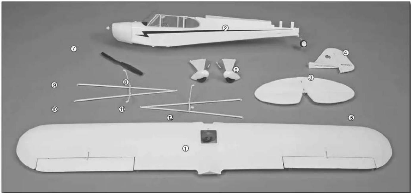
text_image
Exploded view diagram of a small aircraft with numbered parts for identificationKIT CONTENTS
- Wing assembly (aileron servo installed)
- Fuselage assembly (battery hatch, tail gear, motor, ESC, receiver, elevator servo, rudder servo installed)
-
Horizontal stabilizer assembly (elevator hinged to stab)
-
Vertical stabilizer assembly (rudder hinged to fi n)
- Wing strut assembly (2)
- R&L landing gear assembly
- 8.25" Diameter propeller
Not shown: Wire pushrods with Z-bends on one end (3)
ASSEMBLE THE MODEL
Mount the Main Landing Gear
text_image
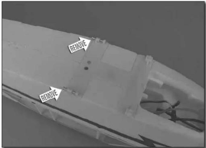
REMOVE REMOVE☐ 1. Remove the preinstalled 2 x 15mm Phillips screws from the aft landing gear mount on the bottom of the fuselage.
natural_image
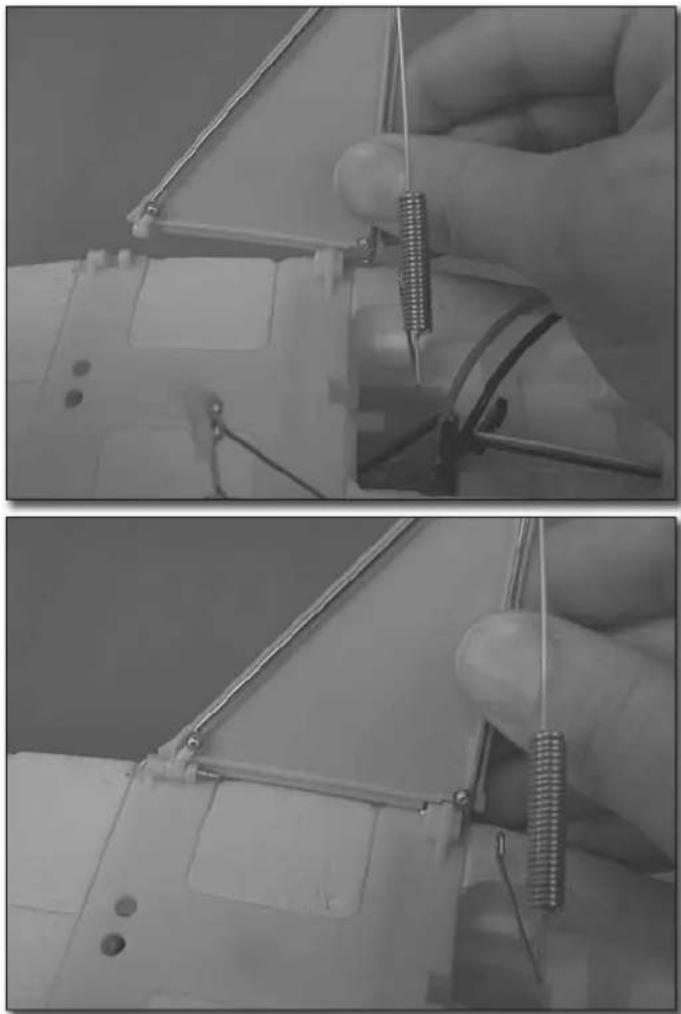
Close-up of hands using a wire tool to connect wires on a mechanical component (no text or symbols visible)☐ 2. Press the landing gear wire in the left main landing gear into the landing gear mount. Then, reinstall the 2 x 15mm
Phillips screw into the aft mount and through the gear, but don't tighten it all the way down yet (the screw will be removed and reinstalled again later when attaching the wing struts). Mount the right main landing gear the same way.
text_image
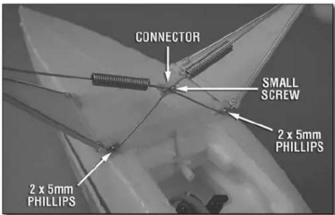
CONNECTOR SMALL SCREW 2 x 5mm PHILLIPS 2 x 5mm PHILLIPS☐ 3. Remove the small screw from the plastic landing gear wire connector that is not already holding in the other gear wire. Insert the other landing gear wire into the connector making sure it is fully seated. Reinstall the screw using care not to over-tighten it. Mount the end of both gear springs to the front, inner mount with 2 x 5mm Phillips screws.
Mount the Vertical & Horizontal Stabilizers (Fin and Stab)
natural_image
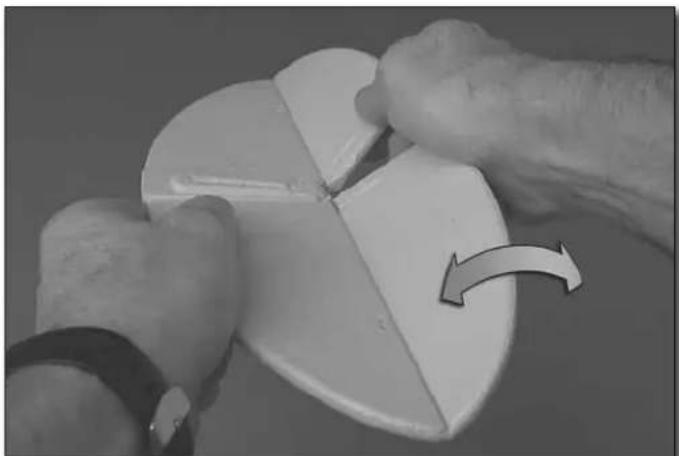
Close-up of hands cutting a white ceramic object with a curved arrow indicating rotation (no text or symbols)☐ 1. Flex the elevators up and down a few times to loosen them up so they move easier.
natural_image
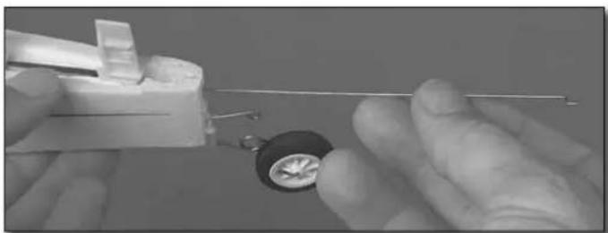
Close-up of hands assembling a small mechanical component with a metallic rod (no visible text or symbols)☐ 2. Insert one of the pushrod wires part way up through the elevator pushrod guide tube in the fuselage.
natural_image
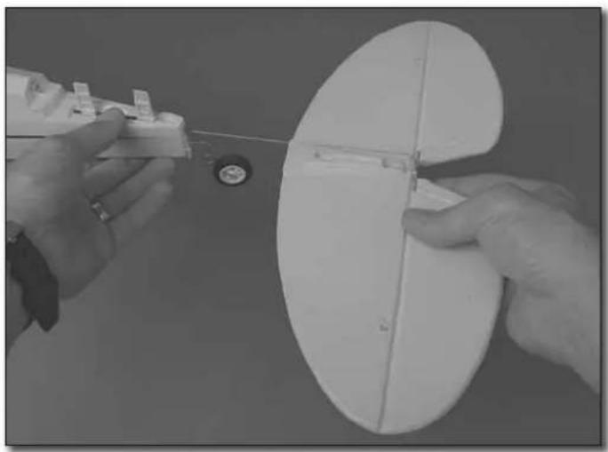
Close-up of hands assembling a white oval-shaped object with a small circular component nearby (no text or symbols visible)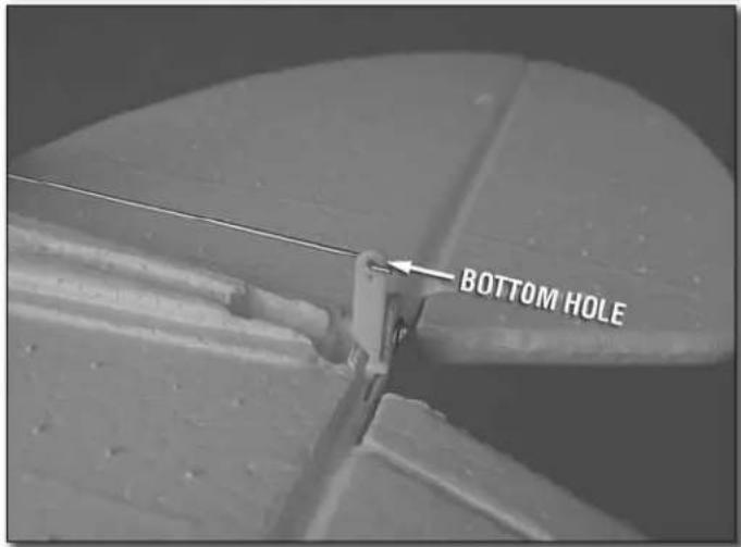
text_image
BOTTOM HOLE☐ 3. Insert the "Z-bend" of the wire into the bottom hole in the elevator horn as shown.
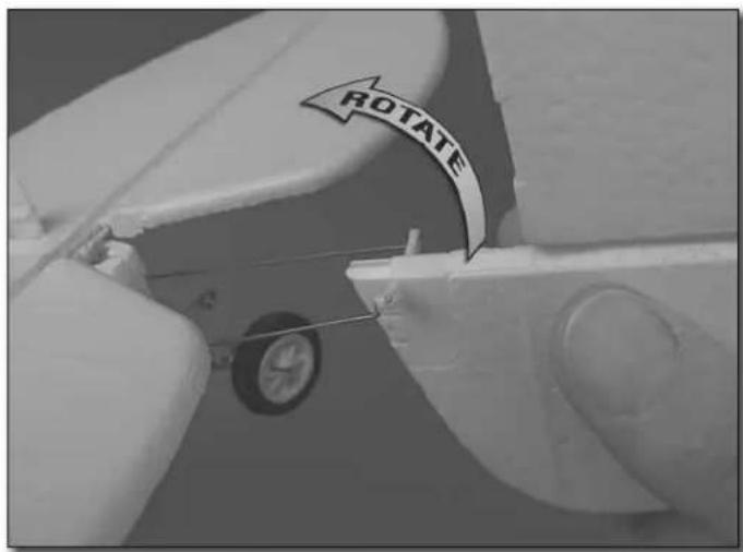
text_image
ROTATE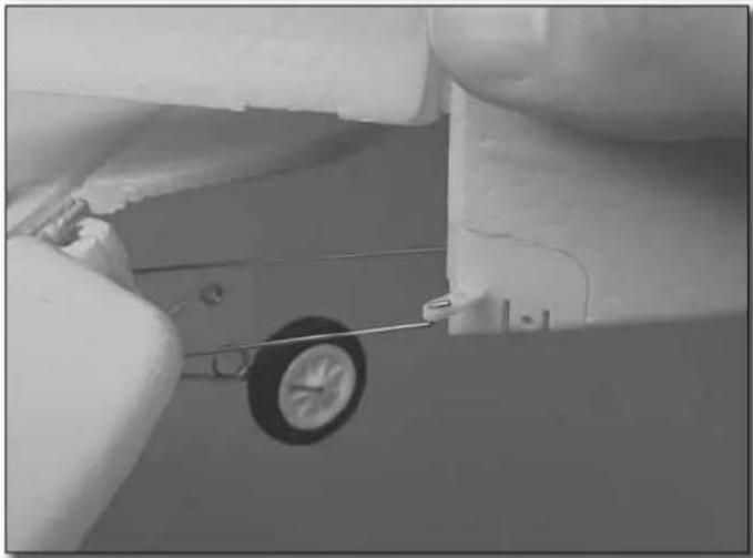
natural_image
Close-up of a jet engine's wing and wheel assembly, showing mechanical components and a handle (no text or symbols visible)☐ 5. Same as the elevator pushrod, guide the two rudder pushrods partway up through the guide tubes in the fuselage. Connect the pushrods to the outer holes in the rudder horn, then rotate the rudder 90° to lock the pushrods in.
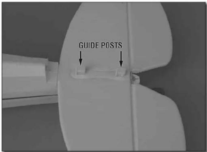
text_image
GUIDE POSTS- Turn the elevator over and fi t it over the molded-in guide posts in the fuselage as you guide the pushrod up through the tube in the fuselage.
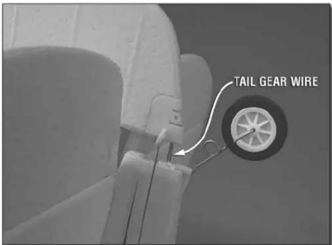
text_image
TAIL GEAR WIRE☐ 6. Prepare to join the vertical stabilizer assembly to the fuselage by inserting the tail gear wire partway into the rudder.
text_image
PULL FORWARD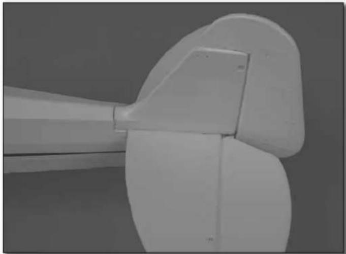
natural_image
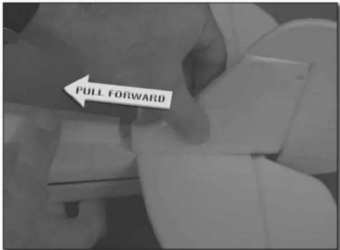
Close-up of a white wind turbine blade with no visible text or symbols- Join the vertical stabilizer (fi n) to the fuselage by placing it over the guide posts sticking up through the stab. Pull the rudder forward, locking it into position.
text_image
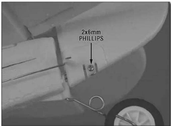
2x6mm PHILLIPS☐ 8. Lock the tail gear into position with a 2x6mm Phillips screw.
Hook Up the Controls
☐ 1. If you haven't yet done so, familiarize yourself with the radio control system you will be using and its functions by reading the instructions that came with it.
text_image
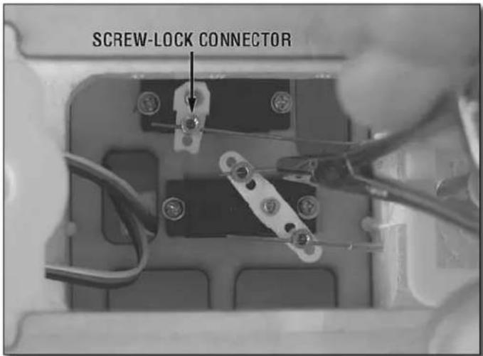
SCREW-LOCK CONNECTOR☐ 2. Use needle-nose pliers or hemostats to guide the pushrod wires into the screw-lock connectors on the elevator and rudder servo arms—if necessary you can rotate the servo arms to get the pushrods in.
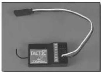
☐ 3. Connect a servo wire extension into the "Aileron" channel in your receiver. On most receivers this will be channel 1.
natural_image
Electronic device with a black body and white wiring, labeled 'TACTIC' (no readable text beyond label)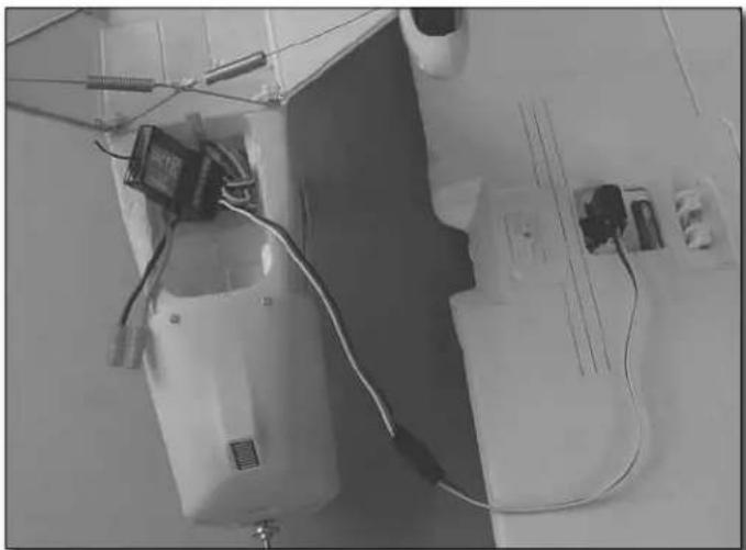
natural_image
Black-and-white photo of a small electronic device with wires and connectors, placed on a workbench (no visible text or symbols)☐ 4. Connect the elevator, rudder and ESC (electronic speed control) wires in the fuselage to the appropriate channels in the receiver, but do not yet mount the receiver in the fuselage. For most receivers channel 2 will be the elevator, channel 3 will be the ESC (throttle) and channel 4 will be the rudder. Also connect the aileron servo in the wing to the aileron servo extension in the receiver.
CAUTION: Perform the following steps without the propeller mounted to the motor. Do not mount the propeller until instructed to do so.
-
Move the throttle stick all the way down and center all the trims on the transmitter (except for the throttle trim, which should be all the way down). Turn on your transmitter and connect the included battery pack to the battery wire coming from the ESC (electronic speed control) in the fuselage. When the connection is made you will hear one or two beeps coming from the ESC. IMPORTANT: The beeping sound alerts you that the system has power and the motor is "armed." This means whenever the throttle control stick is advanced the propeller will turn. So later, when the propeller is mounted and you are ready to fly, keep clear of the propeller while handling the model and do not inadvertently advance the throttle stick. If you do, the propeller will turn and damage or injury could be caused.
-
Move the control sticks on the transmitter to make sure each servo and the motor respond accordingly. If the wrong servos respond to your commands, they are connected to the wrong channels in the receiver. Reconnect the servos to the appropriate channels in the receiver so they respond to the correct commands.
-
Make sure the motor brake function in the ESC is deactivated. When you advance the throttle stick, the motor should turn. When you bring the throttle stick all the way back down, the motor should come to a coasting stop. If the motor stops abruptly, the brake is on. To turn off the brake disconnect the motor battery, but leave the transmitter on. Advance the throttle stick and throttle trim all the way up. Reconnect the battery and listen for one beep. Bring the throttle stick and the throttle trim all the way back down and listen for another single beep. Now the motor brake function is turned off.
The procedure for turning on the motor brake is the same with the exception that two beeps will sound when the brake is being armed.
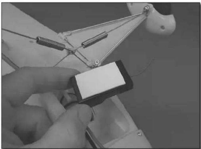
Now that you know all the servos are plugged into the receiver correctly the receiver can be mounted in the fuselage.
natural_image
Close-up of a robotic arm holding a small electronic device with wires and connectors (no visible text or symbols)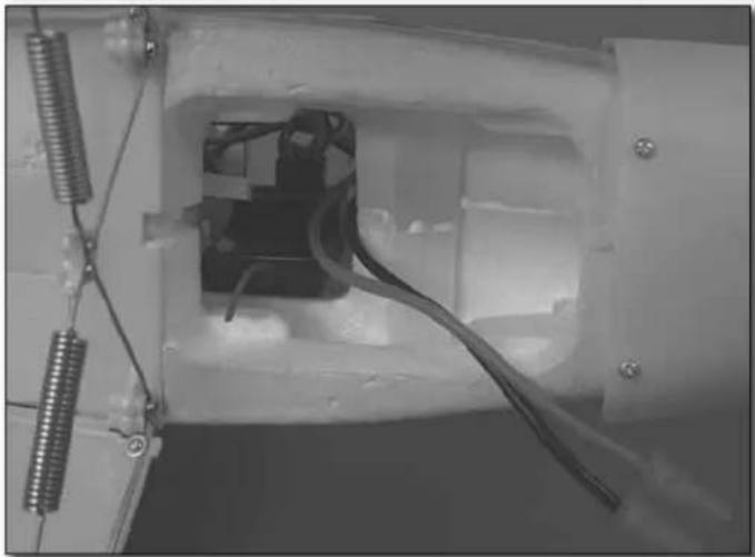
natural_image
Interior view of a mechanical device with visible wiring and components (no text or symbols)☐ 8. Use the included double-sided foam mounting tape to mount the receiver in the fuselage where shown. Make certain the receiver does not interfere with installation of the battery.
natural_image
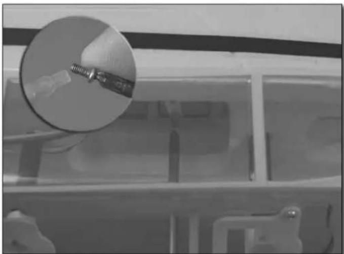
Close-up of a mechanical component with a magnified inset showing a threaded part (no visible text or symbols)- Add a tiny drop of threadlocker to the 2.5 x 5mm Phillips screws and install them into the screw-lock connectors on the elevator and rudder servos, but don't tighten them down yet. If you have diffi culty getting the screws in, it may be easier to hold your screwdriver upright and hold the fuselage upside-down. This way the screws won't fall off the screwdriver.
☐ 10. With the elevator and rudder centered, use hemostats or needle-nose pliers to hold the screw-lock connectors while tightening the screws to lock the pushrods down.
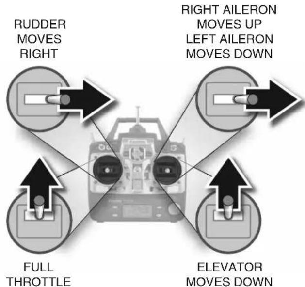
4-CHANNEL RADIO SET UP (STANDARD MODE 2)
flowchart
graph TD
    A["Rudder MOVES RIGHT"] --> B["Central Drone"]
    C["Aileron MOVES UP LEFT Aileron MOVES DOWN"] --> B
    D["Elevator MOVES DOWN"] --> B
    E["Full THROTTLE"] --> B
    B --> F["Arrow Up Right"]
    B --> G["Arrow Down Right"]
☐ 11. Move the sticks on the transmitter and make sure all the controls respond in the correct direction. If any of the controls do not respond in the correct direction, use the servo reversing function in the transmitter to reverse any of the controls necessary.
Check the Control Throws
One major factor that determines how any plane handles in the air is the control surface throw, or how far each control surface (aileron, elevator and rudder) moves up and down or left and right. If the throw is too much, the plane will respond too quickly. If the throw is too little, the plane will respond too slowly. The control throws in your Cub have already been determined by where the pushrods are connected to the servo arms and control surfaces and how far the servo arms rotate. But if you're using a radio control system different than the one recommended, the servo arms could rotate more or less than anticipated, changing the throws. Therefore, it's a good idea to double-check the throws just to make sure they are acceptable. Follow the procedure below to make sure the control throws are properly set.
Measure the elevator throw first:
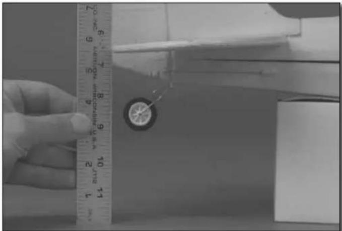
☐ 1. Use a small box or something similar to prop up the aft end of the fuselage so the stab will be level (or nearly level).
natural_image
Close-up of a hand measuring a small object with a ruler, no visible text or symbols on the object itself.☐ 2. Still without the propeller mounted to the motor, turn on your transmitter and connect the battery. Place a ruler to the trailing edge of the elevator at the widest part (from front-to-back).
natural_image
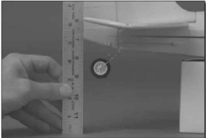
Close-up of a hand measuring a circular object with a ruler, next to a mechanical component (no visible text or symbols)☐ 3. Use your transmitter to move the elevator up and measure the distance it moved from center. This is your "up" control throw. Measure the down elevator control throw the same way. Compare your up and down elevator throw to the recommended elevator throw below. Measure and compare the rudder and aileron throws as well.
| These are the recommended control surface throws: | |||||
| ELEVATOR | RUDDER | AILERONS | |||
| Up | Down | Right | Left | Up | Down |
| 3/8" [9.5mm] 9° | 3/8" [9.5mm] 9° | 1-1/4" [32mm] 30° | 1-1/4" [32mm] 30° | 1/2" [12.7mm] 17° | 1/2" [12.7mm] 17° |
| Note: If you ever install different servos in the plane or use a different radio control system, make sure you set it up so you will have the recommended throws. | |||||
Increased Elevator Throw for Expert Pilots (Optional)
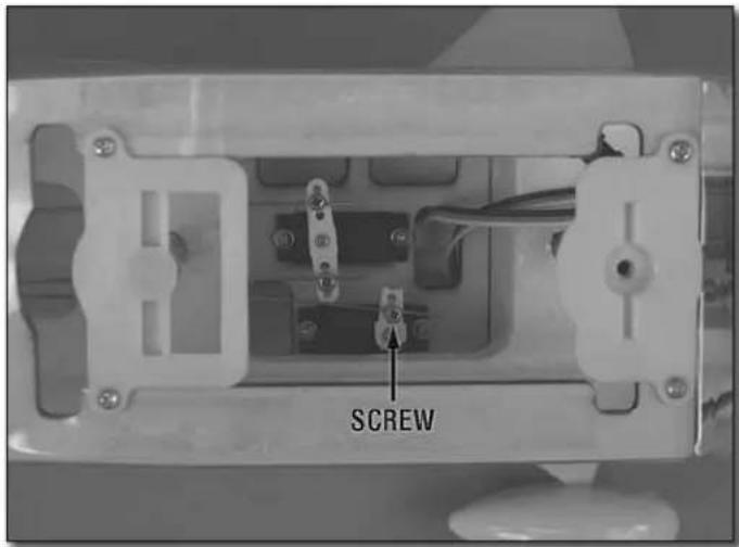
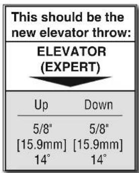
Pilots who have mastered fl ying their Piper Super Cub with the recommended control throws, or pilots who are already experienced, may increase the elevator throw as shown below for even more maneuverability.
text_image
SCREW☐ 1. Loosen the screw in the screw-lock connector on the elevator servo arm and remove the screw in the servo arm. Remove the elevator servo arm from the elevator servo.
text_image
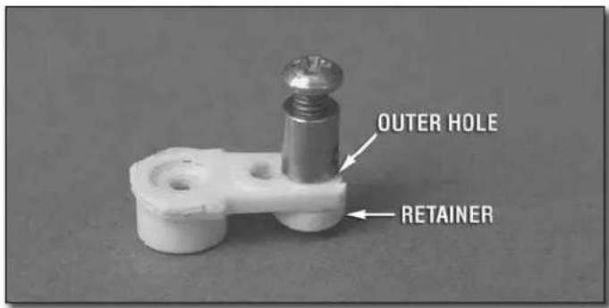
OUTER HOLE RETAINER☐ 2. Remove the retainer, then switch the screw-lock connector from the inner hole to the outer hole. Replace the retainer on the screw-lock connector, then replace the servo arm on the servo with the screw. Center the elevator the same way you did before with the radio on and tighten down the screw in the screw-lock connector to lock the pushrod down.
text_image
This should be the new elevator throw: ELEVATOR (EXPERT) Up Down 5/8" 5/8" [15.9mm] [15.9mm] 14° 14°Mount the Wing

text_image
2" [51mm] 2-1/4" [57mm] 2-1/2" [64mm]☐ 1. For balancing the model later, use a fi ne-point felt-tip pen to mark three balance lines across the bottom of the wing 2" [51mm], 2-1/4" [57mm] and 2-1/2" [64mm] back from the leading edge. The line in the middle is the recommended starting balance point and the forward and aft lines mark the forward and aft balance points.
text_image
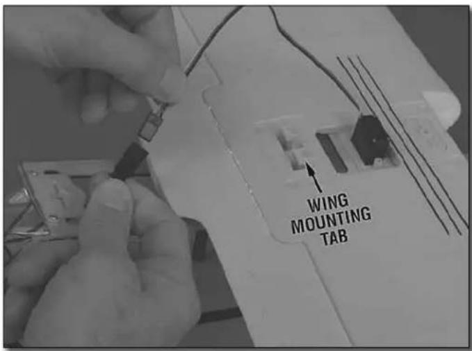
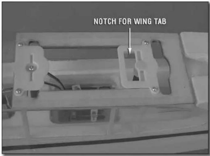
WING MOUNTING TAB☐ 2. Connect the aileron servo wire to the aileron servo extension coming from the receiver.
text_image
NOTCH FOR WING TAB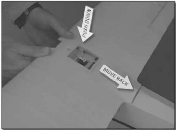
text_image
NOOD HSD MOVE BACK- Turn the wing over. Making sure the aileron servo wire doesn't get caught between the bottom of the wing and the top of the fuselage, key the tab in the wing into the notch just ahead of the aft mounting post. Push the top of the wing down and back to lock it in.
natural_image
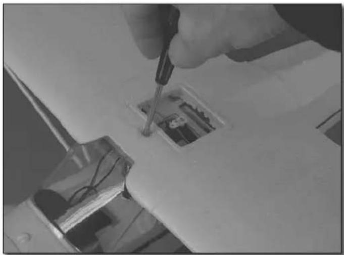
Close-up of a hand using a screwdriver to test electrical components on a circuit board (no visible text or symbols)☐ 4. Fasten the wing to the fuselage with a 3 x 10mm Phillips screw.
natural_image
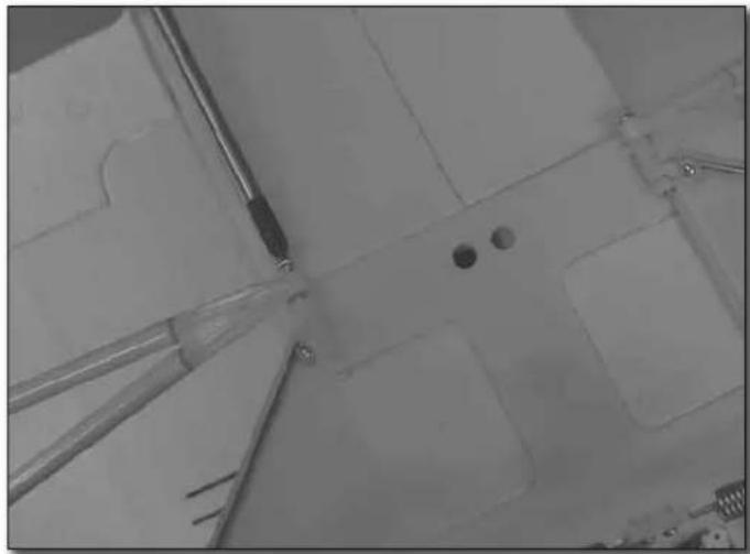
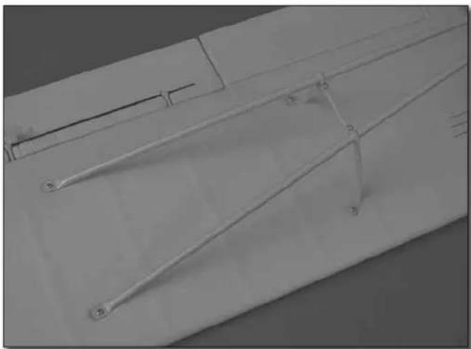
Close-up of a mechanical component with visible pins and mounting holes (no text or symbols)☐ 5. Turn the airplane over. Remove the 2 x 15mm screws that are holding in the rear of the landing gear and mount the ends of the struts with the screws.
natural_image
Pure technical line drawing of a mechanical component without any text, numbers, or symbols☐ 6. Fasten the struts and strut braces to the wing with 2 x 8mm Phillips screws.
FINAL PREPARATION
Mount the Propeller
natural_image
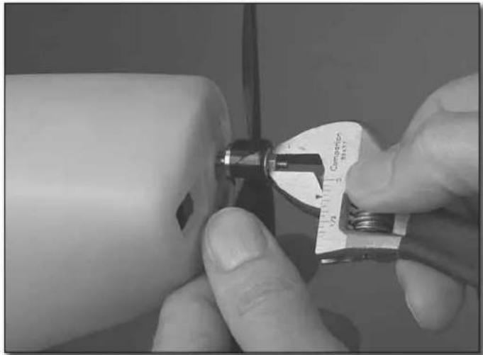
Close-up of a hand using a vernier caliper to measure a small mechanical part (no visible text or symbols)☐ 1. Mount the propeller to the propeller shaft with the washer, nut and a tiny drop of threadlocker on the threads. Tighten the nut with your fingers until it is snug against the washer. Then, use a small crescent wrench to tighten the nut securely. Sometimes, as you tighten the nut, the propeller shaft turns with it causing the nut not to tighten. But if you turn the nut quickly, it should tighten after another turn or two.
For future reference, if you ever need to remove the propeller later, needle-nose pliers may be required to hold the propeller hub behind the propeller to keep the shaft from turning.
☐ 2. Install the propeller spinner by pressing it over the propeller shaft.
natural_image
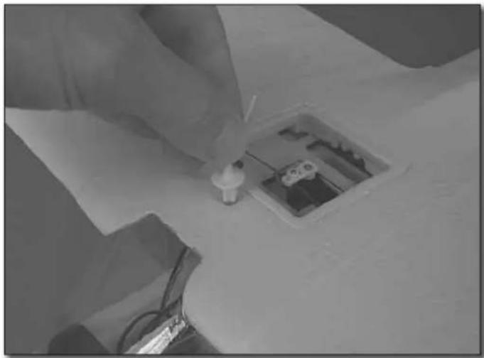
Close-up of a hand inserting a small component into a small electrical socket (no visible text or symbols)☐ 3. Insert the replica antenna into the hole for the wing bolt in the top of the wing.
Check the C.G. (Center of Gravity)
The C.G. (Center of Gravity) is the location on the wing where the model balances and has a great effect on how it will fly. If the C.G. is too far aft (tail heavy), the mode will be too responsive. If the C.G. is too far forward (nose-heavy), the model will not be responsive enough. As provided to you, your Piper Super Cub should already be properly balanced, or very nearly properly balanced, but it's a good idea to check the balance just in case. Follow the instructions to make sure the model is balanced properly and the C.G. is in the correct location.
text_image
Flyzone® Charged at HCAAM310 1300mAh 11.1V 10C 14.4Wh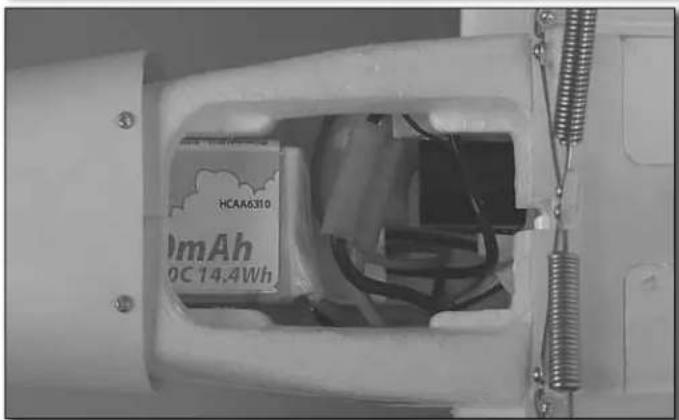
natural_image
Close-up of a white electronic device casing with visible internal components and wiring (no readable text or symbols)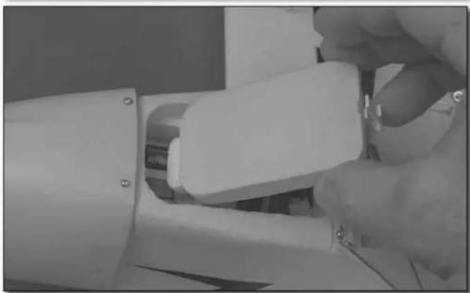
natural_image
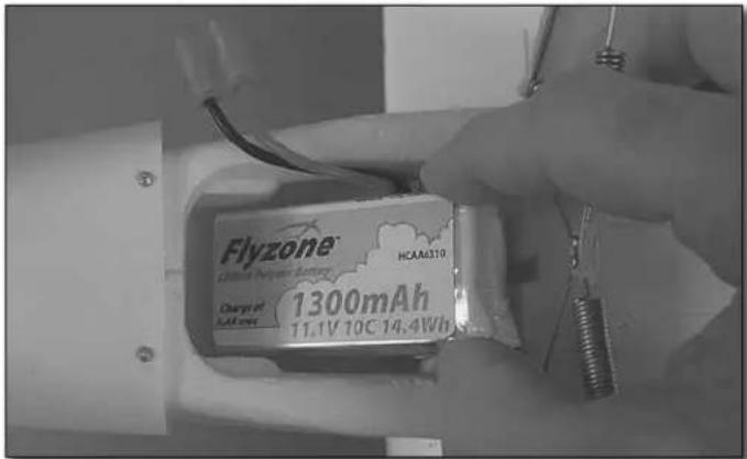
Close-up of a hand inserting a white plastic component into a white cylindrical device (no visible text or symbols)☐ 1. Install the motor battery, but do not connect it to the ESC. Also install the battery hatch. All the rest of the parts of the model should already be installed including the propeller, propeller spinner and the wing struts.
natural_image
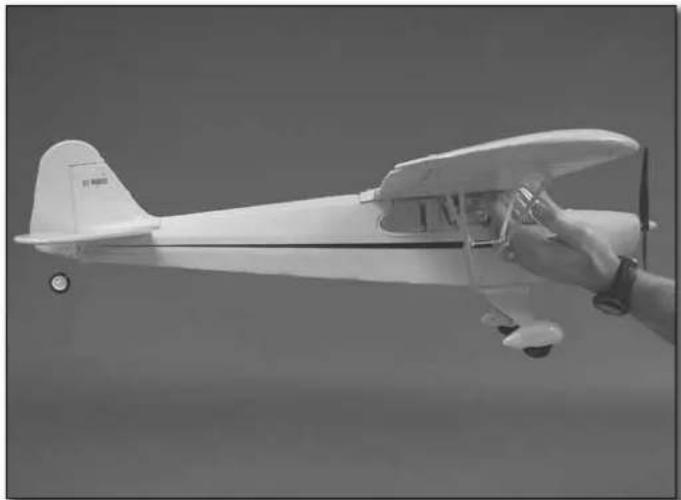
Black-and-white photo of a small model airplane with a hand holding the propeller (no visible text or symbols)☐ 2. You have already marked the balance lines on the bottom of the wings. Now place your fi ngers on the middle balance line and lift the model. The fuselage should remain level—it may be helpful to have an assistant view the model from the side to see. If the fuselage does not rest level try moving your fi ngers under the wing, making certain to keep them between the forward and aft lines. As long as the fuselage is level with your fi ngers between the lines, the balance range is acceptable and the model is ready to fl y. However, even if after moving your fi ngers all the way to the forward lines the nose remains low, tail weight will be required. Or, even if after moving your fi ngers all the way to the rear lines the tail remains low, nose weight will be required. Balance the model as instructed below.
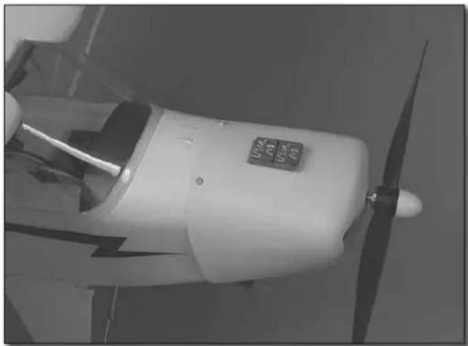
Note: Even if your Cub balances perfectly on the recommended balance point, later you may wish to change its fl ying characteristics by moving the C.G. forward or aft. Moving the C.G. forward (nose heavy) will make the model more stable which may be better for windier days, but this will also make it less maneuverable. Moving the C.G. back (tail heavy) will make the Cub more maneuverable which is good for experienced pilots who wish to perform aerobatics. In any regard, start at the recommended balance point and never fly the model with the C.G. outside of the recommended range.
natural_image
Close-up of a white propeller or fan with visible blades and a control panel (no text or symbols)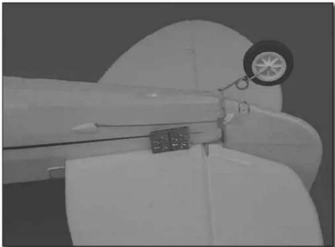
natural_image
Close-up of a mechanical component with a circular dial and attached rod (no visible text or symbols)☐ 3. Determine the amount of weight required by placing segments of Great Planes stick-on lead (GPMQ4485) (or similar) over the cowl or tail where shown, but do not attach it yet.
natural_image
Close-up of a mechanical component with a metal screw and threaded rod inserted, no visible text or symbols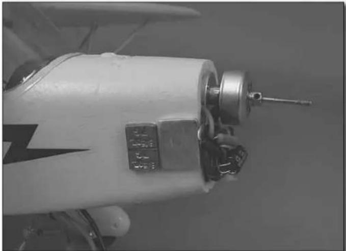
natural_image
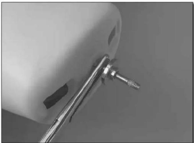
Close-up of a white industrial machine with metal components and a screwdriver (no visible text or symbols)☐ 4. Once you can get the model to balance and you know how much lead will be required, permanently stick it into position. The best place to add nose weight is to the side of the fuselage just behind the weights that are already there. This will require removing the propeller, then the propeller
hub (by holding the shaft with pliers) and then the cowl. Attach the lead, then replace the cowl, propeller and spinner. If tail weight is required, simply attach it to the side of the fuselage under the horizontal stab where shown.
☐ 5. Recheck the C.G. to make certain the model still balances where required. Once fi nished, remove the battery. Never charge the battery while it is installed in the model.
6. Later, once you become an expert at flying your Cub, you may change the flying characteristics by changing the balance point—but do not go beyond the marks you made on the bottom of the wing. Moving the C.G. forward (nose heavy) will improve the model's stability. This could be an advantage on breezy days. Moving the C.G. aft (tail heavy) will make the model more responsive.
GET THE MODEL READY TO FLY
Identify Your Model
No matter if you fl y at an AMA sanctioned R/C club site or if you fl y somewhere on your own, you should always have your name, address, telephone number and AMA number on or inside your model. It is required at all AMA R/C club fl ying sites and AMA sanctioned fl ying events and simply a “good idea” even if fl ying somewhere else. Write this information on a strip of masking tape and place it on the inside of the battery hatch (or simply write the information directly on the battery hatch).
Charge the Battery
Be certain to refer to the instructions that accompany the charger to properly and safely charge the battery. Also read and follow the battery charging precautions that follow.
Battery Charging Precautions
- Be careful to avoid overcharging the battery!
- Remember to check the temperature of the battery during the charge. The batteries should not get hot. If they do, unplug them from the charger.
- If you use a different battery charger, charge this battery pack at a maximum charge rate of 1.8 amps. A higher charge rate will charge the battery pack too quickly and heat up the wires.
- A properly-cared-for battery pack will last a long time. If the battery pack is continually overcharged or charged at too high of a rate, the life of the battery pack will be shortened.
WARNING: Misuse or malfunction may overheat the battery and charger, resulting in personal injury or damage to surroundings.
Battery Recycling
ATTENTION: The product you have purchased is powered by a rechargeable battery. At the end of the battery's useful life, under various state and local laws, it may be illegal to dispose of this battery into the municipal waste system. Check with your local solid waste offi cials for details in your area for recycling options or proper disposal. We encourage contacting your local recycling center for more information.
FLYING THE PIPER Super CUB
Although the Piper Super Cub has the configuration of a trainer (a high wing), due to its small size and lack of self-correcting features it is not necessarily intended for beginners. The Cub is however easy to fl y even for pilots with moderate experience. If you have not previously fl own a trainer it is strongly suggested that you learn to fl y with one fi rst. Or, get the assistance of an experienced pilot to help you with the fi rst few fl ights.
Find a Suitable Flying Site
Find a fl ying site clear of buildings, trees, power lines and other obstructions. Until you know how much area will be required and have mastered fl ying your Cub in confi ned spaces, a site at least the size of two or three football fi elds should be adequate—a fl ying fi eld specifi cally intended for R/C planes is best. Don't fl y within fi ve miles of R/C fl ying fi elds and never fl y near people—especially children who can wander unpredictably.
Know Your Frequency
CAUTION: This applies only to pilots fl ying their Piper Cub with a radio control system that broadcasts on 72MHz. This caution does not apply to pilots fl ying their Cub on 2.4GHz.
Transmitters operating on 72MHz operate on one of several frequencies available. To find your frequency (or "channel"), look at the label on the transmitter. If your channel happens to be the same as another model that is being fl own nearby (even within a few miles), one or both models will crash. Know your frequency and be aware of the frequency of other models that are fl ying nearby—especially if you are fl ying at a radio control fl ying site. All fl ying sites have some sort of frequency control system to avoid this kind of interference, so learn how to use their frequency control system. Never turn on your transmitter until you are certain that you will be the only one operating on your frequency.
Perform a Range Check
As a precaution, an operational ground range test should be performed before the first flight each time you go out. Performing a range test is a good way to detect problems that could cause loss of control such as low batteries, defective or damaged radio components or radio interference. This usually requires an assistant and should be done at the actual flying site you will be using.
First turn on the transmitter, then install the fully-charged battery into the fuselage. Connect the battery and install the hatch.
Remember, use care not to "bump" the throttle stick. Otherwise, the propeller will turn and possibly cause damage or injury.
Follow the instructions that came with your radio control system to perform a ground range check. Make sure you operate the motor and vary the rpm while performing the check. Have your assistant alert you if the controls quit responding or move suddenly or erratically.
If the controls aren't working correctly or if anything seems wrong, don't fly the model until you find and correct the problem. Make certain all the servo wires are securely connected to the receiver and that the transmitter batteries are in good condition.
Monitor Your Flight Time
Monitor and limit your fl ight time using a timer (such as one on a wrist watch or in your transmitter if yours has one). When the batteries are getting low you will usually notice a performance drop before the ESC cuts off motor power, so when the plane starts fl ying slower you should land. Often (but not always), power can be briefl y restored after the motor cuts off by holding the throttle stick all the way down for a few seconds.
To avoid an unexpected dead-stick landing on your fi rst fl ight, set your timer to a conservative 7 minutes (in most conditions the Super Cub will usually fl y for approximately 9 minutes, but this can vary). When your alarm sounds you can either land right away, or if you are an experienced pilot you may continue to fl y until the motor fi nally quits. Then, glide it in for a landing. If planning a “dead-stick,” circle your Cub upwind of the landing area until the motor quits and note the run time.
When you learn how much flight time you are getting you can adjust your timer accordingly. Always be conservative so the motor won't quit unexpectedly and you will have enough battery to land under power.
Take Off
Until you have become comfortable fl ying your Super Cub, do not fl y if the wind speed is greater than 10 mph [16 kph].
One final check before takeoff: always check the fl ight control response to your inputs from the transmitter before every fl ight. Be certain the ailerons, elevator, rudder and throttle respond correctly and that none of the controls have inadvertently become reversed.
Your Cub may takeoff from short grass or pavement. For beginners, short grass is usually best because it stabilizes the wheels, making it easier to keep the plane rolling straight ahead. If the grass is too tall the Cub may also be hand-launched.
ROG (Rise off Ground)
Place the model on the ground with the nose pointing directly into the wind—taking off into the wind reduces the ground speed required for takeoff and helps stabilize the plane, keeping it moving straight ahead. Smoothly but rapidly advance the throttle using the left control stick (rudder) to keep the Cub going straight and the right control stick (ailerons) to keep the wings level. Once the plane becomes “light,” smoothly apply just enough “up” elevator to allow the model to rise into the air—all this will happen in a few seconds. Do not “yank” up on the elevator stick—rather, be smooth and allow the plane to establish a gentle climb
Hand-Launch
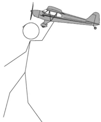
It's easy to hand-launch your Piper Cub, but it's even easier to have an assistant launch it—especially for the first time.
natural_image
Simple line drawing of a stick figure with a propeller airplane flying overhead (no text or symbols)Have your assistant hold the model under the fuselage behind the landing gear. When you have signaled “ready” and your assistant has acknowledged, advance the throttle to full power. The Cub should pretty much fly out of his hand, but it’s a good idea to give it a strong toss at a slightly nose-up attitude. Remind your assistant to do his best to launch the Cub with the wings level. The Cub will initially ascend, then climb once it gains enough flying speed. Apply “up” elevator to start climbing and use the ailerons to keep the wings level.
Flying
text_image
NO! TOO STEEP!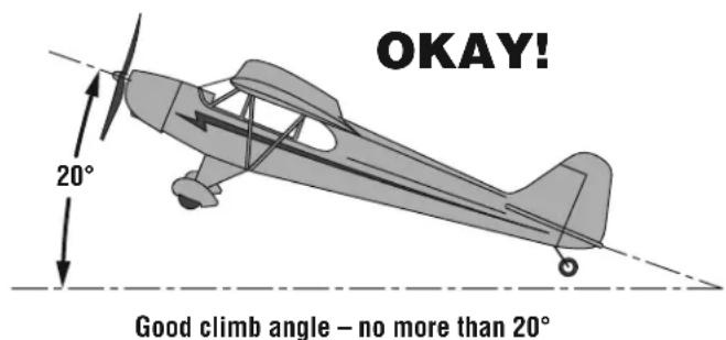
text_image
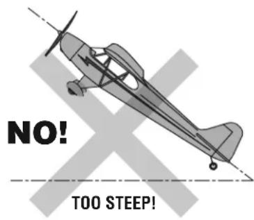
OKAY! 20° Good climb angle – no more than 20°Once the Cub has become airborne, establish a gentle climb at an approximately 20^-30^ angle. Continue climbing and keeping the wings level until the Cub has reached an altitude of approximately 100' [30m] when you can make your first turn away from yourself.
If you already have some fl ight experience and are relatively comfortable fl ying your Cub, the fi rst thing you should do is use the trims to adjust the fl ight controls so the plane will fl y straight-and-level when the control sticks are centered.
If you find yourself in a little over your head and are having difficulty controlling your Cub, your first priority will be simply to keep the model airborne. Concentrate on making smooth turns by using the ailerons to bank the wings and the elevator to control pitch. It may also be a good idea to throttle back some to slow the Cub as well.
One thing for beginner pilots to keep in mind is that when the plane is fl ying away from you, moving the aileron stick to the right will make the plane bank to your right. However, when the model is fl ying toward you, moving the aileron stick to the right will make the plane move to your left. Of course, the plane is still responding the same way, it's just that your orientation is reversed. This must be kept in mind while learning to fl y (and is also a good reason to take fl ight lessons from an experienced pilot!).
To establish a turn, "up" elevator (pulling back on the stick) is usually required along with aileron input to get the model into a bank. To stop the turn, apply a small amount of opposite aileron.
Remember to keep the model high enough to give yourself time to make corrections, but don't let it get too far away. Otherwise, it will be diffi cult to tell what the plane is doing and where it is going. Continue to fly your Cub, getting used to how it responds before fi nally coming in to land.
One final check before landing: see how the model will react when you cut the power. While at altitude, cut the motor power. The model should establish a gentle, downward glide path. This is how it will react when it's actually time to land. Add power and climb back to your original altitude. Practice a few of these "climb and glides" to judge how your Cub react.
Landing
To land, fly down-wind past the landing area. Gently turn into the wind and reduce the throttle so that the airplane initiates an ascending glide path. If necessary, add power to extend the glide path to reach the runway. As the model approaches and loses altitude, gradually and proportionally, add "up" elevator to control the glide path and altitude. Continue to apply elevator until the model touches down at which time you should be holding full, or nearly full up elevator. This will cause the airplane to slow and settle to the ground.
Caution: If, during a rough landing, the propeller becomes jammed and cannot rotate, the battery and speed control will become very hot. Immediately move the throttle down to stop the motor. If you fail to do this, the motor, speed control and/or battery will be damaged.
After Flight
Disconnect the battery and remove it from the airplane. Then turn off the transmitter. Inspect the airplane to make sure nothing has become loose or damaged. Allow the battery to cool before recharging, or allow the motor to cool for a few minutes before installing another battery and fl ying again.