Calypso - Remote control toy Flyzone - Free user manual and instructions
Find the device manual for free Calypso Flyzone in PDF.


User questions about Calypso Flyzone
0 question about this device. Answer the ones you know or ask your own.
Ask a new question about this device
Download the instructions for your Remote control toy in PDF format for free! Find your manual Calypso - Flyzone and take your electronic device back in hand. On this page are published all the documents necessary for the use of your device. Calypso by Flyzone.
USER MANUAL Calypso Flyzone
natural_image
Model of a white aircraft with propeller wings and tail fin, labeled 'CALYPSO' (no additional text or symbols visible)Manual Supplement
Refer to this Instruction Manual Supplement for initial assembly of your Calypso ARF. After completing the assembly steps in this supplement, continue with the twenty-page RTF/Rx-R/Tx-R Calypso instruction manual booklet.
In addition to the items listed in the instruction manual for the Rx-R edition, the Calypso ARF also requires the following items:
○ 18A ESC (Electronic Speed Controller) (FLZA6011)
○ C28-30 1300kV brushless motor (FLZA6012)
○ Spinner, folding propeller set (FLZA6006)
(4) Calypso micro servos (FLZA6013), or any of the Futaba® micro servos that have the same case as the S3117 such as the following:
S3117 (FUTM0417)
S3157 (FUTM0657)
S3156 (FUTM0656)
○ (2) 18"-24" [460 mm-610 mm] servo wire extensions for aileron servos (HCAM2200 for Futaba J)
The ailerons may be mixed electronically through the mixing in your transmitter, or "hard-wired" together into the same channel with a Y-harness (FUTM4130).
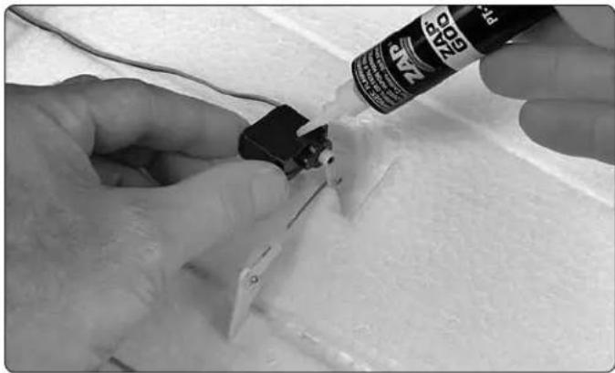
The Calypso may be assembled with just about any kind of glue including foam-safe or regular CA, but for gluing in the servos something thicker and fl exible is preferred such as Zap Goo or similar (PAAR3200).
○ A 1.5mm Allen wrench is required for tightening the set screws in the folding propeller hub (DTXR0288).
○ Non-permanent threadlocker for all metal-to-metal screws (GPMR6060)
ASSEMBLY
Assemble the Wings
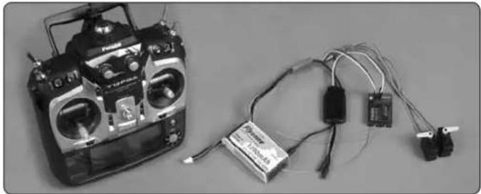
First, let's center the aileron servo arms before gluing the servos into the wing...
natural_image
Black-and-white photo of a multi-wheeled radio with connected cables and a battery pack (no visible text or symbols)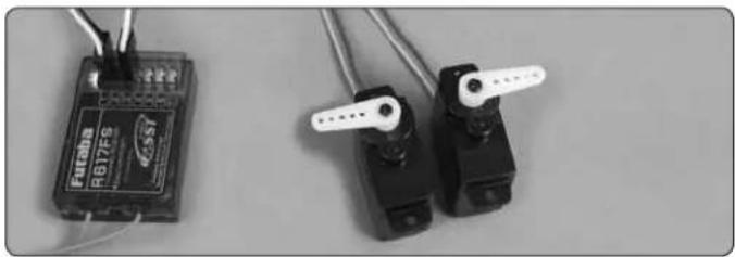
natural_image
Close-up of a black R617F8 device with wires and two black mechanical limbs, no visible text or symbols.☐ 1. Temporarily connect the aileron servos and ESC to your receiver and turn on your transmitter. Making sure the trims on your transmitter are centered, connect the battery to the ESC. If necessary, remove and re-mount the servo arms so they will be perpendicular as shown. Be certain to replace the servo arm screws.
You may work on both wings simultaneously, or do one wing at a time.
natural_image
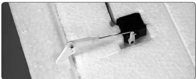
Close-up of a mechanical lever mechanism with a black handle and metal bracket, mounted on a textured surface (no visible text or symbols)☐ 2. Without using any glue, temporarily fit the servos into the pockets in the wing. Hook up the ailerons with the hardware shown.
natural_image
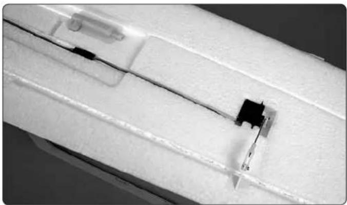
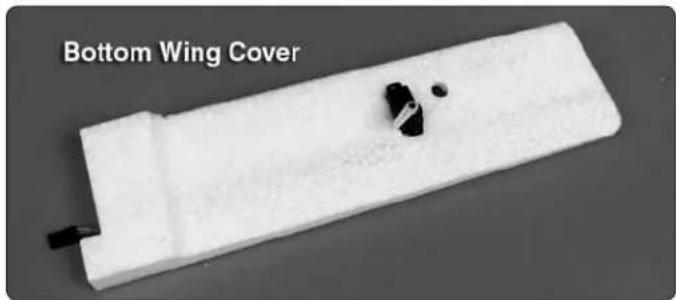
Close-up of a white structural component with black connectors and a small black component, no visible text or symbols.☐ 3. Connect a 18" - 24" [460mm - 610mm] servo extension to the aileron servo wires and secure the connection with tape,
heat shrink tubing or a dab of glue. Lay the servo wires down inside the channels.
natural_image
White 3D-printed object with black and white components, labeled 'Bottom Wing Cover' (text is part of the image)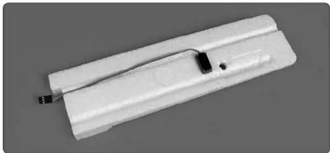
natural_image
White plastic electronic device with a small black component and a small hole, shown against a neutral gray background (no text or symbols visible)☐ 4. If you plan to hook up the optional fl aps, it will be a little easier to cut the fl ap servo openings in the bottom wing covers and fi t the fl ap servos at this time, so go ahead and do so—but fi rst refer to the illustration at step 13 on page 11 of the Calypso instruction manual for the correct orientation of the fl ap servos and servo arms. If unsure whether or not you will be using fl aps, the servo installation and hookup is easy enough to retrofi t later (as illustrated on page 8 of the instruction manual).

natural_image
Close-up of a white plastic mechanical component with a small black component and two small dots, held by a finger (no text or symbols visible)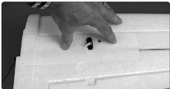
natural_image
Close-up of a hand pressing down on a white electronic device component (no visible text or symbols)☐ 5. Without using any glue, test-fi t the bottom wing cover to the wing. Make sure the cover lays all the way down fl at into the cavity and make any adjustments necessary.
natural_image
Close-up of hands using a spray can to apply material to a small mechanical component (no visible text or symbols)☐ 6. Glue the aileron servos (and fl ap servos if installed) into position—thick or medium CA is suitable, but if ever necessary, the servos will be easier to extract later if something more fl exible such as Zap Goo or similar is used.
natural_image
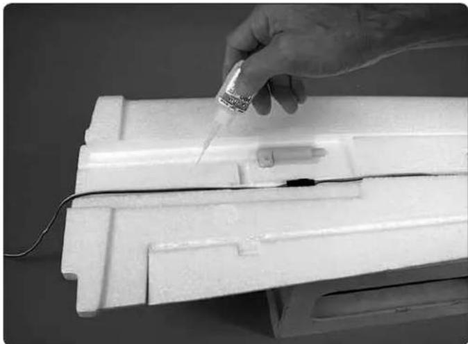
Hand using a pipette to test internal components on a white plastic base (no text or symbols visible)☐ 7. Glue the bottom wing cover into position—thick or medium CA is okay here, but use care not to allow any glue to leak into the channel or into the clamp for the joiner tube. If necessary, use tape or weights to hold the cover down until the glue hardens.
text_image
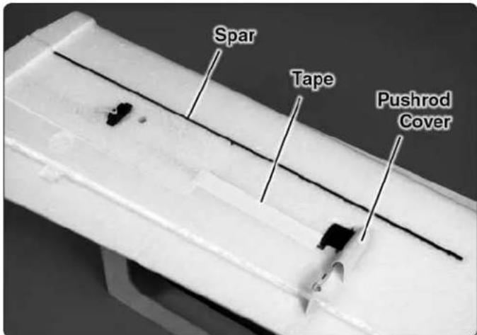
Spar Tape Pushrod Cover☐ 8. Glue the spars and optional aileron pushrod covers into position. Also apply a strip of white or clear tape over the channel for the aileron servo wire.
Assemble the Fuselage

text_image
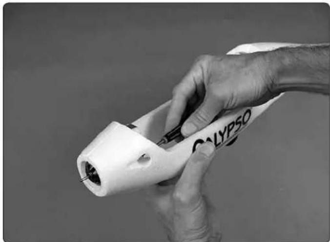
THREADLOCKER CREAT PLANES PRO 100% DRY SPRINGAR 200g/100 gm 100g/100 gm 100g/100 gm 100g/100 gm 100g/100 gm 100g/100 gm 100g/100 gm 100g/100 gm 100g/100 gm 100g/100 gm 100g/100 gm SPRINGAR 100g/100 gm 100g/100 gm 100g/100 gm 100g/100 gm 100g/100 gm 100g/100 gm 100g/100 gm 100g/100 gm 100g/100 gm 100g/100gmNon-permanent threadlocker should be used on all screws that thread into metal such as the motor mount screws, the set screws in the propeller hub and the screws that secure the spinner—a large amount of threadlocker is not required—just enough to "wet" the first few threads.
natural_image
Close-up of a gloved hand holding a white cylindrical device labeled 'CALYPSO' (no additional text or symbols visible)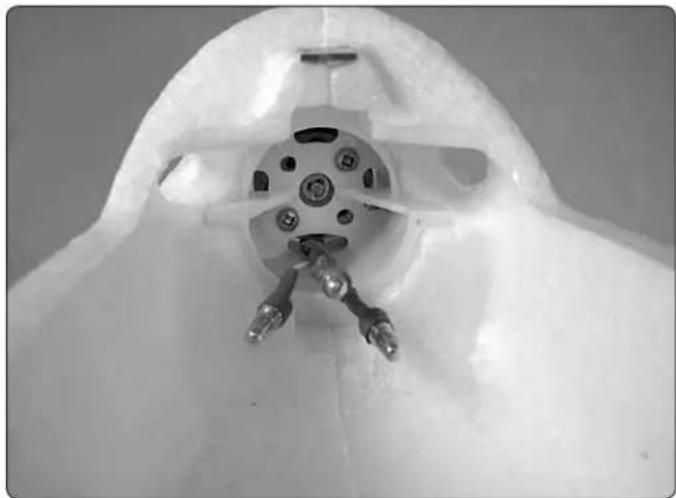
natural_image
Close-up of a white mechanical component with metallic pins and a central hub (no visible text or symbols)- Guide the motor wires through the oval hole in the bottom of the motor mount. Then, mount the motor with the two 3 x 5mm screws (don't forget to use threadlocker on the screws).
text_image
Propeller Hub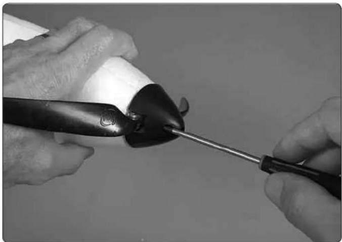
natural_image
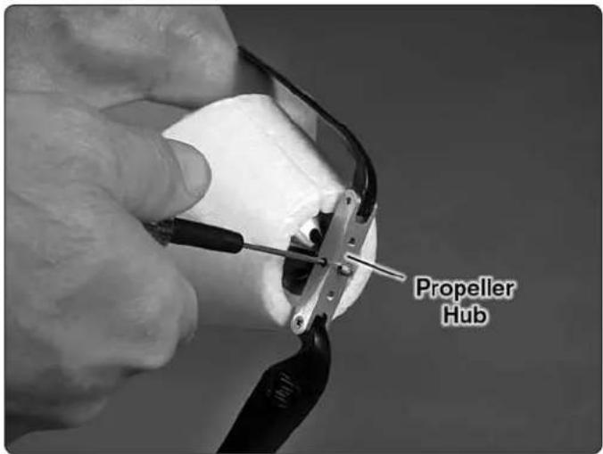
Close-up of hands using a pliers to apply material, no visible text or symbols☐ 2. Fasten the propeller hub onto the motor shaft using a 1.5mm hex wrench to tighten the set screws. Then, mount the spinner with the 3 x 12mm screws.
natural_image
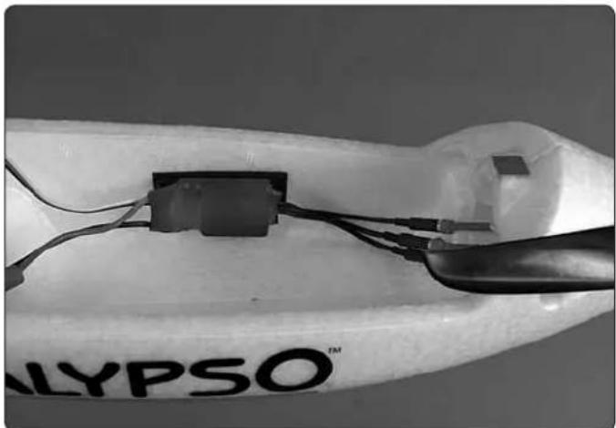
Close-up of a medical or laboratory setup with electronic components and wires, no visible text or symbols☐ 3. Connect the ESC to the motor and mount the ESC to the inside of the fuselage with strips of the included adhesive-back hook-and-loop material. Note: If, while running up the motor later, the propeller turns backward, simply switch any two of the three motor wires with each other to make the motor turn the other direction.
natural_image
Close-up of a gloved hand holding wires next to a small rectangular electronic component (no visible text or symbols)-
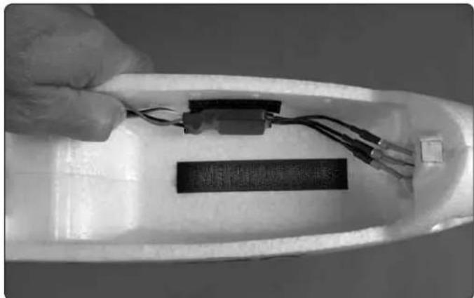
Apply a strip of the rougher, "hook-side" of the hook-and-loop material to the bottom of the radio compartment for the battery. Apply thin or medium CA all the way around the edges of the strip to make certain it is adhered permanently.
-
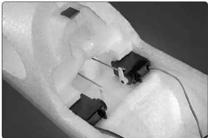
Same as was done with the aileron servos, temporarily power up the elevator and rudder servos with your radio system and make sure the arms are perpendicular.
natural_image
Close-up of a transparent plastic mechanical component with embedded black components and wires (no visible text or symbols)- Install the pushorods through the guide tubes in the fuselage. Then, connect the pushrods to the outer holes in the servo arms. Glue the servos into position.
natural_image
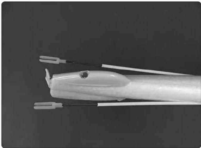
Close-up of a white plastic object with multiple white connectors and wires, no visible text or symbols- Thread the clevises onto the pushrods until the end of each pushrod protrudes through the clevis just enough to become visible.
Congratulations! Your Calypso ARF is now a Calypso Rx-R and you may continue assembly using the full Calypso instruction manual.

text_image
Flyzone™ how high will you soar^8 Inc. All rights reserved.
Champaign, Illinois (217) 398-8970
E-mail: airsupport@hobbico.com