Vigor 2926 - Router Draytek - Free user manual and instructions
Find the device manual for free Vigor 2926 Draytek in PDF.


User questions about Vigor 2926 Draytek
0 question about this device. Answer the ones you know or ask your own.
Ask a new question about this device
Download the instructions for your Router in PDF format for free! Find your manual Vigor 2926 - Draytek and take your electronic device back in hand. On this page are published all the documents necessary for the use of your device. Vigor 2926 by Draytek.
USER MANUAL Vigor 2926 Draytek
Your reliable networking solutions partner
natural_image
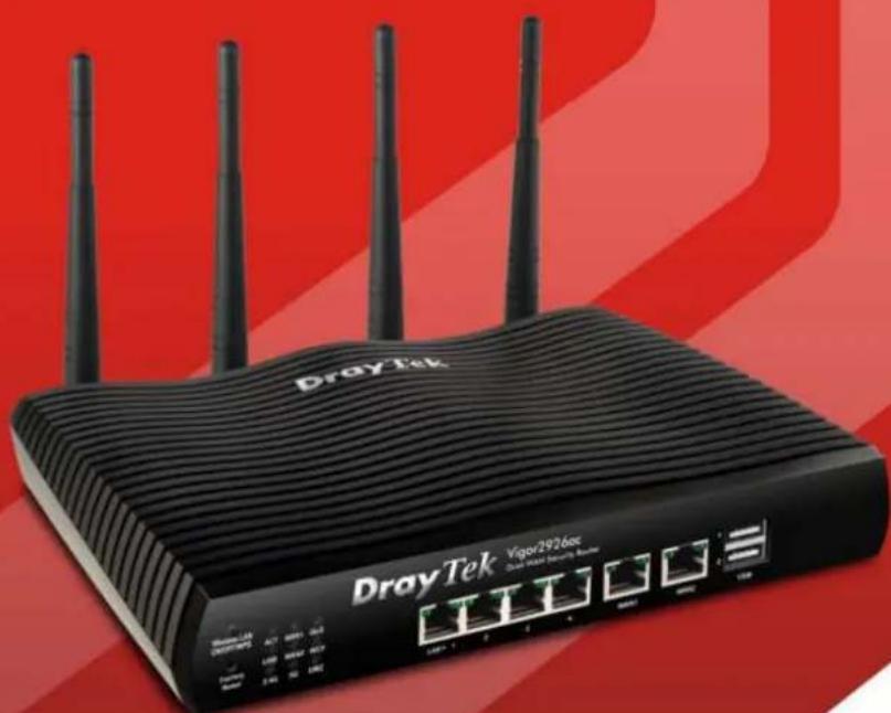
DrayTek Viper 2926xx network router with four antennas against a red background (no readable text or symbols beyond branding)User's Guide
V1.4
Vigor2926 Series
Dual-WAN Security Router
User's Guide
Version: 1.4
Firmware Version: V3.9.1.1
(For future update, please visit DrayTek web site)
Date: September 30, 2019
Copyrights
© All rights reserved. This publication contains information that is protected by copyright. No part may be reproduced, transmitted, transcribed, stored in a retrieval system, or translated into any language without written permission from the copyright holders.
Trademarks
The following trademarks are used in this document:
● Microsoft is a registered trademark of Microsoft Corp.
● Windows, Windows 95, 98, Me, NT, 2000, XP, Vista, 7 and Explorer are trademarks of Microsoft Corp.
● Apple and Mac OS are registered trademarks of Apple Inc.
● Other products may be trademarks or registered trademarks of their respective manufacturers.
Safety Instructions
- Read the installation guide thoroughly before you set up the router.
- The router is a complicated electronic unit that may be repaired only be authorized and qualified personnel. Do not try to open or repair the router yourself.
- Do not place the router in a damp or humid place, e.g. a bathroom.
● The router should be used in a sheltered area, within a temperature range of +5 to +40 Celsius. - Do not expose the router to direct sunlight or other heat sources. The housing and electronic components may be damaged by direct sunlight or heat sources.
● Do not deploy the cable for LAN connection outdoor to prevent electronic shock hazards. - Keep the package out of reach of children.
- When you want to dispose of the router, please follow local regulations on conservation of the environment.
Warranty
We warrant to the original end user (purchaser) that the router will be free from any defects in workmanship or materials for a period of two (2) years from the date of purchase from the dealer. Please keep your purchase receipt in a safe place as it serves as proof of date of purchase. During the warranty period, and upon proof of purchase, should the product have indications of failure due to faulty workmanship and/or materials, we will, at our discretion, repair or replace the defective products or components, without charge for either parts or labor, to whatever extent we deem necessary tore-store the product to proper operating condition. Any replacement will consist of a new or re-manufactured functionally equivalent product of equal value, and will be offered solely at our discretion. This warranty will not apply if the product is modified, misused, tampered with, damaged by an act of God, or subjected to abnormal working conditions. The warranty does not cover the bundled or licensed software of other vendors. Defects which do not significantly affect the usability of the product will not be covered by the warranty. We reserve the right to revise the manual and online documentation and to make changes from time to time in the contents hereof without obligation to notify any person of such revision or changes.
Be a Registered Owner
- Web registration is preferred. You can register your Vigor router via http://www.DrayTek.com.
Firmware & Tools Updates
- Due to the continuous evolution of DrayTek technology, all routers will be regularly upgraded. Please consult the DrayTek web site for more information on newest firmware, tools and documents.
http://www.DrayTek.com
Contacting DrayTek
If the router still cannot work correctly after trying many efforts, please contact your dealer for further help right away. For any questions, please feel free to send e-mail to support@DrayTek.com.
Table of Contents
Part I Installation....i
I-1 Introduction ...... 1
I-1-1 Indicators and Connectors 2
I-1-1-1 For Vigor2926 / Vigor2926L 2
I-1-1-2 For Vigor2926n / Vigor2926ac / Vigor2926Lac / Vigor2926Ln.... 4
I-1-1-3 For Vigor2926Vac 8
I-1-2 Notes for Antenna Installation (for "L" model) 10
I-2 Hardware Installation 12
I-2-1 Installing Vigor Router 12
I-2-2 Wall-Mounted Installation 13
I-2-3 Installing USB Printer to Vigor Router 14
I-3 Accessing Web Page 21
I-4 Changing Password....23
I-5 Dashboard....24
I-5-1 Virtual Panel 25
I-5-2 Name with a Link 25
I-5-3 Status for LTE 26
I-5-4 Quick Access for Common Used Menu 26
I-5-5 GUI Map 27
I-5-6 Web Console 28
I-5-7 Config Backup 29
I-5-8 Manual....29
I-5-9 Logout....29
I-5-10 Online Status 30
I-5-10-1 Physical Connection....30
I-5-10-2 Virtual WAN....33
I-6 Quick Start Wizard 34
I-6-1 For WAN1/WAN2 (Ethernet) 35
I-6-2 For WAN3/WAN4 (USB) 43
I-6-3 For LTE WAN 45
I-7 Service Activation Wizard 47
I-8 MyVigor Services 50
I-8-1 Registering Vigor Router 50
I-8-2 Service Status 54
Part II Connectivity ....57
II-1 WAN 58
Web User Interface....60
II-1-1 General Setup 60
II-1-1-1 WAN1/WAN2 with Ethernet 63
II-1-1-2 WAN3/WAN4 (USB)....65
II-1-2 Internet Access....67
II-1-2-1 Details Page for PPPoE in WAN1/WAN2 (Physical Mode: Ethernet) 70
II-1-2-2 Details Page for Static or Dynamic IP in WAN1/WAN2 (Physical Mode: Ethernet) 73
II-1-2-3 Details Page for PPTP/L2TP in WAN1/WAN2 (Physical Mode: Ethernet) ..... 76
II-1-2-4 Details Page for 3G/4G USB Modem (PPP mode) in WAN3/WAN4....79
II-1-2-5 Details Page for 3G/4G USB Modem (DHCP mode) in WAN3/WAN4....81
II-1-2-6 Details Page for 3G/4G USB Modem (DHCP mode) in LTE WAN ....83
II-1-2-7 Details Page for IPv6 - Offline in WAN1/ WAN2/ WAN3/ WAN4....87
II-1-2-8 Details Page for IPv6 - PPP in WAN1/ WAN2 88
II-1-2-9 Details Page for IPv6 - TSPC in WAN1/ WAN2/ WAN3/ WAN4....89
II-1-2-10 Details Page for IPv6 - AICCU in WAN1/ WAN2/ WAN3/ WAN4....91
II-1-2-11 Details Page for IPv6 - DHCPv6 Client in WAN1/WAN2....93
II-1-2-12 Details Page for IPv6 - Static IPv6 in WAN1/WAN2 94
II-1-2-13 Details Page for IPv6 - 6in4 Static Tunnel in WAN1/WAN2....96
II-1-2-14 Details Page for IPv6 - 6rd in WAN1/ WAN2 ...... 97
II-1-3 Multi-VLAN 99
II-1-4 WAN Budget.... 104
II-1-4-1 General Setup 104
II-1-4-2 Status 107
Application Notes 108
A-1 How to set up Multi-VLAN for triple play deployment?...... 108
A-2 Load Balancing and Failover for multi-WAN Vigor Routers.... 113
II-2 LAN 115
Web User Interface 117
II-2-1 General Setup 117
II-2-1-1 Details Page for LAN1 - Ethernet TCP/IP and DHCP Setup.... 119
II-2-1-2 Details Page for LAN2 \~ LAN8 and DMZ 123
II-2-1-3 Details Page for IP Routed Subnet 125
II-2-1-4 Details Page for LAN IPv6 Setup.... 126
II-2-1-5 Advanced DHCP Options 130
Application Notes 132
A-1 Multi-subnet Application - How to utilize Vigor router with non-NAT? 132
II-2-2 VLAN 135
II-2-3 Bind IP to MAC 140
II-2-4 LAN Port Mirror.... 143
II-2-5 Wired 802.1x 144
II-3 Hardware Acceleration.... 145
II-3-1 Setup 145
II-4 NAT 147
Web User Interface 148
II-4-1 Port Redirection.... 148
II-4-2 DMZ Host 152
II-4-3 Open Ports 155
II-4-4 Port Triggering.... 157
II-4-5 ALG....159
II-5 Applications....160
Web User Interface 162
II-5-1 Dynamic DNS 162
II-5-2 LAN DNS / DNS Forwarding 168
II-5-3 DNS Security 171
II-5-3-1 General Setup 171
II-5-3-2 Domain Diagnose 172
II-5-4 Schedule....173
II-5-5 RADIUS/TACACS+ 175
II-5-5-1 External RADIUS.... 175
II-5-5-2 Internal RADIUS 177
II-5-5-3 External TACACS+.... 180
II-5-6 Active Directory/LDAP 181
II-5-6-1 General Setup 181
II-5-6-2 Active Directory / LDAP Profiles 182
II-5-7 UPnP 183
II-5-8 IGMP 184
II-5-8-1 General Setting 184
II-5-8-2 Working Status 185
II-5-9 Wake on LAN 186
II-5-10 SMS / Mail Alert Service.... 187
II-5-10-1 SMS Alert 187
II-5-10-2 Mail Alert 188
II-5-11 Bonjour 189
II-5-12 High Availability 192
II-5-12-1 General Setup.... 193
II-5-12-2 Config Sync 195
II-5-13 Local 802.1X General Setup 197
Application Notes 199
A-1 How to use High Availability?...... 199
A-2 How to use DrayDDNS? 207
A-3 How to Configure Customized DDNS?...... 212
A-4 How to Implement the LDAP/AD Authentication for User Management? ..... 216
II-6 Routing....219
Web User Interface 220
II-6-1 Static Route 220
II-6-2 Load-Balance /Route Policy 226
II-6-2-1 General Setup 226
II-6-2-2 Diagnose 231
II-6-3 BGP 234
II-6-3-1 Basic Settings.... 234
II-6-3-1 Static Network 235
Application Notes 236
A-1 How to set up Address Mapping with Route Policy? 236
A-2 How to use destination domain name in a route policy? 238
A-3 How to use a Public IP on LAN 240
A-4 Introduction to Load Balance/ Route Policy 245
II-7 LTE 248
Web User Interface 249
II-7-1 General Settings.... 249
II-7-1-1 SMS Quota.... 249
II-7-1-2 SMS Inbox/ Outbox Policy 250
II-7-2 SMS Inbox 251
II-7-3 Send SMS 254
II-7-4 Router Commands 255
II-7-5 Status 257
Part III Wireless LAN....259
III-1 Wireless LAN (2.4GHz/5GHz) 260
Web User Interface 263
III-1-1 Wireless Wizard....263
III-1-2 General Setup 267
III-1-3 Security 269
III-1-4 Access Control 272
III-1-5 WPS....274
III-1-6 WDS 277
III-1-7 Advanced Setting 281
III-1-8 Station Control....283
III-1-9 Bandwidth Management....284
III-1-10 AP Discovery 285
III-1-11 Airtime Fairness....286
III-1-12 Band Steering.... 288
III-1-13 Roaming 292
III-1-14 Station List....293
Part IV VoIP....295
IV-1 VoIP 296
Web User Interface 298
IV-1-1 VoIP Wizard 298
IV-1-2 General Settings 300
IV-1-3 SIP Accounts.... 303
IV-1-4 DialPlan....308
IV-1-4-1 Phone Book.... 308
IV-1-4-2 Digit Map 310
IV-1-4-3 Call Barring 312
IV-1-4-4 Regional 314
IV-1-4-5 PSTN Setup 315
IV-1-5 Phone Settings.... 316
IV-1-6 Status 320
IV-1-7 Diagnostics.... 322
IV-1-7-1 Caller ID 322
IV-1-7-2 Tone 322
Part V VPN 323
V-1 VPN and Remote Access 324
Web User Interface 325
V-1-1 VPN Client Wizard 325
V-1-2 VPN Server Wizard 332
V-1-3 Remote Access Control 336
V-1-4 PPP General Setup.... 337
V-1-5 IPsec General Setup 339
V-1-6 IPsec Peer Identity 340
V-1-7 OpenVPN 343
V-1-7-1 General Setup 343
V-1-7-2 Client Config.... 344
V-1-8 Remote Dial-in User 346
V-1-9 LAN to LAN 349
V-1-10 VPN Trunk Management 360
V-1-11 Connection Management.... 369
Application Notes 371
A-1 How to Build a LAN-to-LAN VPN Between Vigor Routers via IPsec Main Mode ... 371
A-2 How to Build a LAN-to-LAN VPN Between Vigor Routers via IKEv2.... 376
V-2 SSL VPN 379
Web User Interface 380
V-2-1 General Setup 380
V-2-2 User Account.... 381
V-2-3 User Group.... 385
V-2-4 Online User Status 387
V-3 Certificate Management.... 388
Web User Interface 389
V-3-1 Local Certificate 389
V-3-2 Trusted CA Certificate.... 393
V-3-3 Certificate Backup.... 395
V-3-4 Self-Signed Certificate 396
Part VI Security ....397
VI-1 Firewall 398
Web User Interface 400
VI-1-1 General Setup 400
VI-1-2 Filter Setup 405
VI-1-3 Defense Setup 415
VI-1-3-1 DoS Defense 415
VI-1-3-2 Spoofing Defense 418
VI-1-4 Diagnose 418
Application Notes 421
A-1 How to Configure Certain Computers Accessing to Internet 421
VI-2 Central Security Management (CSM) 425
Web User Interface 426
VI-2-1 APP Enforcement Profile 426
VI-2-2 APPE Signature Upgrade 428
VI-2-3 URL Content Filter Profile 430
VI-2-4 Web Content Filter Profile 434
VI-2-5 DNS Filter Profile 438
Application Notes 440
A-1 How to Create an Account for MyVigor 440
A-2 How to Block Facebook Service Accessed by the Users via Web Content Filter / URL
Content Filter 445
Part VII Management ....451
VII-1 System Maintenance 452
Web User Interface 453
VII-1-1 System Status 454
VII-1-2 TR-069 456
VII-1-2-1 ACS and CPE Settings 456
VII-1-2-2 Reporting Configuration 458
VII-1-2-3 Export Parameters 459
VII-1-3 Administrator Password 460
VII-1-4 User Password 463
VII-1-5 Login Page Greeting 466
VII-1-6 Configuration Backup.... 468
VII-1-7 Syslog/Mail Alert 471
VII-1-8 Time and Date.... 474
VII-1-9 SNMP 475
VII-1-10 Management 477
VII-1-10-1 IPv4 Management Setup 477
VII-1-10-2 IPv6 Management Setup 479
VII-1-10-3 LAN Management Setup.... 480
VII-1-11 Panel Control 481
VII-1-11-1 LED 481
VII-1-11-2 Button 482
VII-1-11-3 USB 483
VII-1-11-4 LAN Port 483
VII-1-12 Self-Signed Certificate 484
VII-1-13 Reboot System....486
VII-1-14 Firmware Upgrade 487
VII-1-15 Firmware Backup 488
VII-1-16 Activation.... 489
VII-1-17 Internal Service User List....491
VII-1-18 Dashboard Control 492
VII-2 Bandwidth Management.... 493
Web User Interface 495
VII-2-1 Sessions Limit 495
VII-2-2 Bandwidth Limit.... 497
VII-2-3 Quality of Service 499
VII-2-4 APP QoS 505
VII-3 User Management....507
Web User Interface 508
VII-3-1 General Setup....508
VII-3-2 User Profile 510
VII-3-3 User Group....515
VII-3-4 User Online Status 516
Application Notes 518
A-1 How to authenticate clients via User Management 518
A-2 How to use Landing Page Feature 527
VII-4 Hotspot Web Portal....532
Web User Interface 532
VII-4-1 Profile Setup.... 532
VII-4-1-1 Login Method.... 533
VII-4-1-2 Steps for Configuring a Web Portal Profile 533
VII-4-2 User Information.... 550
VII-4-2-1 User Info 550
VII-4-2-2 Database Setup 551
VII-4-3 Quota Management 553
VII-4-4 PIN Generator 556
VII-4-4-1 PIN Status.... 556
VII-4-4-2 PIN Generator 557
VII-4-4-3 PIN Voucher 558
Application Notes 560
A-1 How to allow users login to Vigor's Hotspot with their social media accounts (e.g.,
Facebook & Google) 560
A-2 How to allow hotspot clients to get login PIN code via SMS?...... 568
VII-5 Central Management (VPN) 575
Web User Interface 576
VII-5-1 General Setup 576
VII-5-1-1 General Settings.... 576
VII-5-1-2 IPsec VPN Settings.... 577
VII-5-2 CPE Management....578
VII-5-2-1 Managed Device List 578
VII-5-2-2 CPE Maintenance 581
VII-5-2-3 Google Map.... 584
VII-5-3 VPN Management.... 585
VII-5-4 Log & Alert 586
Application Notes 587
A-1 CVM Application - How to manage the CPE (router) through Vigor2926 series? . 587
A- 2 CVM Application - How to build the VPN between remote devices and Vigor2926
series? 591
A-3 CVM Application - How to upgrade CPE firmware through Vigor2926 series?.... 593
VII-6 Central Management (AP)....596
Web User Interface 597
VII-6-1 Dashboard....597
VII-6-2 Status 598
VII-6-3 WLAN Profile....599
VII-6-4 AP Maintenance....604
VII-6-5 AP Map 605
VII-6-6 Traffic Graph 610
VII-6-7 Rogue AP Detection....611
VII-6-8 Event Log 614
VII-6-9 Total Traffic 614
VII-6-10 Station Number 615
VII-6-11 Load Balance 615
Application Notes 617
A-1 How to use AP Management function (in Vigor2926) to check AP status and deploy WLAN profile.... 617
VII-7 Central Management (Switch) 620
Web User Interface 621
VII-7-1 Status 621
VII-7-1-1 Switch Status.... 621
VII-7-1-2 Switch Hierarchy 624
VII-7-1-3 Detailed Info 625
VII-7-2 Profile 626
VII-7-3 Group 630
VII-7-4 Maintenance....632
VII-7-5 Alert and Log....633
VII-7-5-1 Alert Setup 633
VII-7-5-2 Switch and Port Setup 634
VII-7-5-3 Alert Logs.... 636
VII-7-6 Database Setup 637
VII-7-7 Support List....638
VII-8 Central Management (External Devices) 639
Part VIII Others....641
VIII-1 Objects Settings....642
Web User Interface 643
VIII-1-1 IP Object 643
VIII-1-2 IP Group....647
VIII-1-3 IPv6 Object.... 648
VIII-1-4 IPv6 Group 650
VIII-1-5 Service Type Object....651
VIII-1-6 Service Type Group 653
VIII-1-7 Keyword Object....655
VIII-1-8 Keyword Group 657
VIII-1-9 File Extension Object 658
VIII-1-10 SMS/Mail Service Object 660
VIII-1-11 Notification Object 665
VIII-1-12 String Object 667
VIII-1-13 Country Object 668
Application Notes 671
A-1 How to Send a Notification to Specified Phone Number via SMS Service in WAN Disconnection 671
VIII-2 USB Application 675
Web User Interface 676
VIII-2-1 USB General Settings 676
VIII-2-2 USB User Management 677
VIII-2-3 File Explorer 679
VIII-2-4 USB Device Status....680
VIII-2-5 Temperature Sensor 681
VIII-2-6 Modem Support List....683
VIII-2-7 SMB Client Support List....684
Application Notes 685
A-1 How can I get the files from USB storage device connecting to Vigor router? ... 685
Part IX Troubleshooting 689
IX-1 Diagnostics 690
Web User Interface 691
IX-1-1 Dial-out Triggering....691
IX-1-2 Routing Table....692
IX-1-3 ARP Cache Table 693
IX-1-4 IPv6 Neighbour Table 694
IX-1-5 DHCP Table 695
IX-1-6 NAT Sessions Table 696
IX-1-7 DNS Cache Table 697
IX-1-8 Ping Diagnosis 698
IX-1-9 Data Flow Monitor 699
IX-1-10 Traffic Graph 702
IX-1-11 VPN Graph....703
IX-1-12 Trace Route 704
IX-1-13 Syslog Explorer 705
IX-1-14 IPv6 TSPC Status 706
IX-1-15 High Availability Status 707
IX-1-16 Authentication Information 709
IX-1-17 DoS Flood Table 710
IX-1-18 Route Policy Diagnosis 711
IX-2 Checking If the Hardware Status Is OK or Not 713
IX-3 Checking If the Network Connection Settings on Your Computer Is OK or Not.... 714
IX-4 Pinging the Router from Your Computer 717
IX-5 Checking If the ISP Settings are OK or Not.... 718
IX-6 Problems for 3G/4G Network Connection....719
IX-7 Backing to Factory Default Setting If Necessary 720
Part X Telnet Commands....721
Accessing Telnet of Vigor2926 722
Index 982
Part I Installation

This part will introduce Vigor router and guide to install the device in hardware and software.
I-1 Introduction
This is a generic International version of the user guide. Specification, compatibility and features vary by region. For specific user guides suitable for your region or product, please contact local distributor.
Vigor2926 series integrates IP layer QoS, NAT session/ bandwidth management to help users control works well with large bandwidth.
By adopting hardware-based VPN platform and hardware encryption of AES/ DES/ 3DES, the router increases the performance of VPN greatly, and offers several protocols (such as IPSec/ PPTP/ L2TP) with VPN tunnels.
The object-based design used in SPI (Stateful Packet Inspection) firewall allows users to set firewall policy with ease. CSM (Content Security Management) provides users control and management in IM (Instant Messenger) and P2P (Peer to Peer) more efficiency than before. By the way, DoS/ DDoS prevention and URL/ Web content filter strengthen the security outside and control inside. Object-based firewall is flexible and allows your network be safe.
User Management implemented on your router firmware can allow you to prevent any computer from accessing your Internet connection without a username or password. You can also allocate time budgets to your employees within office network.
With the 6-port Gigabit switch on the LAN side provides extremely high speed connectivity for the highest speed local data transfer of any server or local PCs. The tagged VLANs (IEEE802.1Q) can mark data with a VLAN identifier. This identifier can be carried through an onward Ethernet switch to specific ports. The specific VLAN clients can also pick up this identifier as it is just passed to the LAN. You can set the priorities for LAN-side QoS. You can assign each of VLANs to each of the different IP subnets that the router may also be operating, to provide even more isolation. The said functionality is tag-based Multi-subnet (Multiple-Private LAN Subnets).
On the Wireless-equipped models (Vigor2926n/ n-plus/ Vn/ Vn-plus/ ac/ Vac) each of the wireless SSIDs can also be grouped within one of the VLANs.
In addition, Vigor2926 series supports USB interface for connecting USB printer to share printing function or 3G USB modem for network connection.
Vigor2926 series provides two-level management to simplify the configuration of network connection. The user mode allows user accessing into WEB interface via simple configuration. However, if users want to have advanced configurations, they can access into WEB interface through admin mode.
I-1-1 Indicators and Connectors
Before you use the Vigor router, please get acquainted with the LED indicators and connectors first.
I-1-1-1 For Vigor2926 / Vigor2926L

text_image
DrayTek Vigor2926 Dual-WAN Security Router Factory Reset ACT WAN1 CoS USB1 WAN2 WCF USB2 VPN DMZ LAN+ P1 P2 P3 P4 WAN1 P5 / WAN2 USB 1 2
text_image
DrayTek Vigor2926L Dual-WAN Security Router Factory Reset ACT WAN1 Qo8 LTE WAN2 WCF USB VPN DMZ LAN P1 P2 P3 P4 WAN1 P5 / WAN2 USBLED Status Explanation
| ACT (Activity) | Blinking | The router is powered on and running normally. |
| Off The router is powered off. | ||
| WAN1~WAN2 | On Internet connection is ready. | |
| Off Internet connection is not ready. | ||
| Blinking The data is transmitting. | ||
| QoS | On The QoS function is active. | |
| LTE | On SIM card is connected and running normally. | |
| Off LTE device is not detected or encounters troubles (e.g., No SIM, SIM PIN error, SIM deactivated) | ||
| Blinking Quickly: The data is transmitting.Slowly: LTE device is in dialing up procedure. | ||
| USB | On USB device is connected and ready for use. USB1~USB2/ | |
| Blinking The data is transmitting. | ||
| WCF On The Web Content Filter is active. (It is enabled from Firewall >> General Setup). | ||
| VPN | On The VPN tunnel is active. | |
| Off VPN service is disabled. | ||
| Blinking Traffic is passing through VPN tunnel. | ||
| DMZ | On The DMZ function is enabled. | |
| Off The DMZ function is disabled. | ||
| Blinking The data is transmitting. | ||
LED on Connector
| LAN1~LAN4 | Left LED | On The port is connected. |
| Off The port is disconnected. | ||
| Blinking The data is transmitting. | ||
| Right LED | On The port is connected with 1000Mbps. | |
| Off The port is connected with 10/100Mbps. | ||
| WAN1~ WAN2 | Left LED | On The port is connected. |
| Off The port is disconnected. | ||
| Blinking The data is transmitting. | ||
| Right | On The port is connected with 1000Mbps. |
LED
Off The port is connected with 10/100Mbps

text_image
DrayTek Vigor2926 Dual-WAN Security Router Factory Reset ACT WAN1 Q3 USB1 WAN2 W2 USB2 VPN DL2 LAN P1 P2 P3 P4 WAN1 PS1 WAN2 USB
text_image
DrayTek Vigor2926L Dual-WAN Security Router Factory Reset ACT WAN1 Ccs LTE WAN2 WCF USB VPN DMZ LAN P1 P2 P3 P4 WAN1 P5 / WAN2 USB

Switch on Rear Side (Jack for LTE device)
Interface Description
| Factory Reset Restore the default settings. Usage: Turn on the router (ACT LED is blinking). Press the hole and keep for more than 5 seconds. When you see the ACT LED begins to blink rapidly than usual, release the button. Then the router will restart with the factory default configuration. | |
| LAN1~LAN5 | Connecters for local network devices. |
| WAN1~WAN2 Connector for local network devices or modem for accessing Internet. | |
| USB1~USB2 Connector for a USB device (for 3G/4G USB Modem or printer or Environmental Thermometer). | |
| PWR Connector for a power adapter. | |
| ON/OFF | Power Switch. |
| SIM Card Slot Connector for a SIM card. | |
The port "P5 / WAN2" is switchable. It can be used for LAN connection or WAN connection according to the settings configured in WUI.
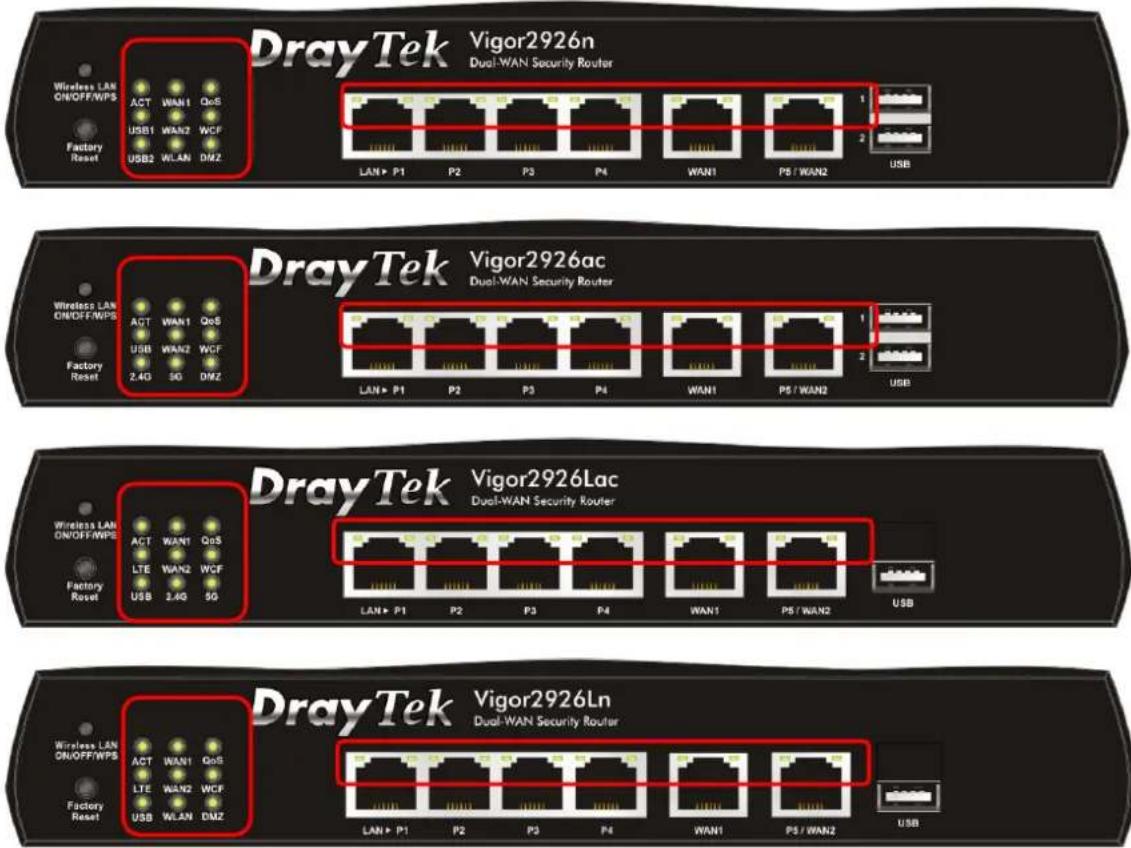
I-1-1-2 For Vigor2926n / Vigor2926ac / Vigor2926Lac / Vigor2926Ln
text_image
DrayTek Vigor2926n Dual-WAN Security Router Wireless LAN ON/OFF/WPS ACT WAN1 QoS USB1 WAN2 WCF Factory Reset USB2 WLAN DMZ LAN+ P1 P2 P3 P4 WAN1 P5 / WAN2 USB DrayTek Vigor2926ac Dual-WAN Security Router Wireless LAN ON/OFF/WPS ACT WAN1 QoS USB WAN2 WCF Factory Reset 2.4G SG DMZ LAN+ P1 P2 P3 P4 WAN1 P5 / WAN2 USB DrayTek Vigor2926Lac Dual-WAN Security Router Wireless LAN ON/OFF/WPS ACT WAN1 QoS LTE WAN2 WCF Factory Reset USB 2.4G SG LAN+ P1 P2 P3 P4 WAN1 P5 / WAN2 USB DrayTek Vigor2926Ln Dual-WAN Security Router Wireless LAN ON/OFF/WPS ACT WAN1 QoS LTE WAN2 WCF Factory Reset USB WLAN DMZ LAN+ P1 P2 P3 P4 WAN1 P5 / WAN2 USBLED Status Explanation
| ACT (Activity) | Blinking | The router is powered on and running normally. |
| Off The router is powered off. | ||
| WAN1~WAN2 | On Internet connection is ready. | |
| Off Internet connection is not ready. | ||
| Blinking The data is transmitting. | ||
| QoS | On The QoS function is active. | |
| LTE | On SIM card is connected and running normally. | |
| Off LTE device is not detected or encounters troubles (e.g., No SIM, SIM PIN error, SIM deactivated) | ||
| Blinking Quickly: The data is transmitting.Slowly: LTE device is in dialing up procedure. | ||
| On USB device is connected and ready for use. USB | ||
| Blinking The data is transmitting. | ||
| WCF On The Web Content Filter is active. (It is enabled from Firewall >> General Setup). | ||
| 2.4G/ 5G/ WLAN | On | 2.4G/ 5G: Wireless access point with bandwidth of 2.4GHz/ 5GHz is ready.WLAN: Wireless access point is ready. |
| Blinking | It will blink slowly while wireless traffic goes through.ACT and WLAN LEDs blink quickly and simultaneously when WPS is working, and will return to normal condition after two minutes. (You need to setup WPS within 2 minutes.) | |
| DMZ | On The DMZ function is enabled. | |
| Off The DMZ function is disabled. | ||
| Blinking The | data is transmitting. | ||
| LED on Connector | |||
| LAN1~ LAN4 | Left LED | On The port | s connected. |
| Off The port | is disconnected. | ||
| Blinking The | data is transmitting. | ||
| Right LED | On The port | s connected with 1000Mbps. | |
| Off The port | is connected with 10/ 100Mbps | ||
| WAN1 ~ WAN2 | Left LED | On The port | s connected. |
| Off The port | is disconnected. | ||
| Blinking The | data is transmitting. | ||
| Right LED | On The port | s connected with 1000Mbps. | |
| Off The port | is connected with 10/ 100Mbps | ||
The port "P5 / WAN2" is switchable. It can be used for LAN connection or WAN connection according to the settings configured in WUI.

text_image
DrayTek Vigor2926n Dual-WAN Security Router Wireless LAN GND/FF/WPS ACT WAN1 QoS USB1 WAN2 WCF Factory Reset USB2 WLAN DMZ LAN▶ P1 P2 P3 P4 WAN1 P5 / WAN2 USB
text_image
DrayTek Vigor2926ac Dual WAN Security Router Wireless LAN ON/OFF/WPS ACT WAN1 QoS USB WAN2 WCF Factory Reset L4G SG DMZ LAN• P1 P2 P3 P4 WAN1 PS / WAN2 USB
text_image
DrayTek Vigor2926Lac Dual-WAN Security Router Wireless LAN ON/OFF/WPS ACT WAN1 QoS TE WAN2 WCF Factory Reset USB 2.4G 5G LAN P1 P2 P3 P4 WAN1 P5 / WAN2 USB
text_image
DrayTek Vigor2926Ln Dual-WAN Security Router Wireless LAN CNOFF/WPS ACT WAN1 QoS LTE WAN2 WCF Factory Reset USB WLAN DMZ LANP P1 P2 P3 P4 WAN1 P5/WAN2 USB
Switch on Rear Side

(Jack for LTE device)
| Interface Description | ||
| Wireless LANON/ OFF/ WPS | For Vigor2926n:Press the button and release it within 2 seconds. When the wireless function is ready, the green LED will be on.Press the button and release it within 2 seconds to turn off the WLAN function. When the wireless function is not ready, the LED will be off.For Vigor2926ac/ Vigor2926Lac / Vigor2926Ln:Wireless band will be switched / changed according to the button pressed and released. For example,2.4G (On) and 5G (On) - in default.2.4G (Off) and 5G (On) - pressed and released the button once.2.4G (On) and 5G (Off) - pressed and released the button twice.2.4G (Off) and 5G (Off) - pressed and released the button three times.When WPS function is enabled by web user interface, press this button for more than 2 seconds to wait for client's device making network connection through WPS. | |
| Factory Reset Restore | the default settings. Usage: Turn on the router (ACT LED is blinking). Press the hole and keep for more than 5 seconds.When you see the ACT LED begins to blink rapidly than usual, release the button. Then the router will restart with the factory | |
| default configuration. | ||
| LAN1~LAN4 | Connecters for local network devices. | |
| WAN1~WAN2 Connector for local network devices or modem for accessing Internet. | ||
| USB1~2 / USB Connector for a USB device (for 3G/ 4G USB Modem or printer or thermometer). | ||
| PWR Connector for a power adapter. | ||
| ON/OFF | Power Switch. | |
| SIM Card Slot Connector for a SIM card. | ||
I-1-1-3 For Vigor2926Vac

text_image
DrayTek Vigor2926Vac Dual-WAN Security Router Wireless LAN ON/OFFY PS ACT WAN1 Line USB WAN2 Phone Factor Reset 2.4G 5G Phone LAN+ P1 P2 P3 P4 WAN1 P5 / WAN2 USB Phone1/2 LineLED Status Explanation
| ACT (Activity) | Blinking | The router is powered on and running normally. |
| Off The router is powered off. | ||
| WAN1~ WAN2 | On Internet connection is ready. | |
| Off Internet connection is not ready. | ||
| Blinking The data is transmitting. | ||
| Line | On A PSTN phone call comes (in and out). However, when the phone call is disconnected, the LED will be off. | |
| Off There is no PSTN phone call. | ||
| On USB device is connected and ready for use. USB | ||
| Blinking The data is transmitting. | ||
| Phone1/ Phone2 | On The phone connected to this port is off-hook. | |
| Off The phone connected to this port is on-hook. | ||
| Blinking A phone call comes. | ||
| 2.4G/ 5G | On | Wireless access point with bandwidth of 2.4GHz/ 5GHz is ready. |
| Blinking | It will blink slowly while wireless traffic goes through. ACT and WLAN LEDs blink quickly and simultaneously when WPS is working, and will return to normal condition after two minutes. (You need to setup WPS within 2 minutes.) | |
LED on Connector
| LAN1~ LAN4 | Left LED | On The port | s connected. |
| Off The port | is disconnected. | ||
| Blinking The | data is transmitting. | ||
| Right LED | On The port | is connected with 1000Mbps. | |
| Off The port | is connected with 10/ 100Mbps | ||
| WAN1 ~ WAN2 | Left LED | On The port | s connected. |
| Off The port | is disconnected. | ||
| Blinking The | data is transmitting. | ||
| Right LED | On The port | is connected with 1000Mbps. | |
| Off The port | is connected with 10/ 100Mbps |
The port "P5 / WAN2" is switchable. It can be used for LAN connection or WAN connection according to the settings configured in WUI.

text_image
DrayTek Vigor2926Vac Dual-WAN Security Router Wireless LAN ON/OFF/MPS ACT WAN1 Line USB WAN2 Phone1 Factory Reset 2.4G 5G Phone2 LAN > P1 P2 P3 P4 WAN1 P5 / WAN2 1 2 USB Phone1/2 Line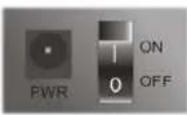
| Interface Description | |
| Wireless LANON/ OFF/ WPS | Wireless band will be switched / changed according to the buttonpressed and released. For example,2.4G (On) and 5G (On) - in default.2.4G (Off) and 5G (On) - pressed and released the button once.2.4G (On) and 5G (Off) - pressed and released the button twice.2.4G (Off) and 5G (Off) - pressed and released the button three times.When WPS function is enabled by web user interface, press thisbutton for more than 2 seconds to wait for client's device makingnetwork connection through WPS. |
| Factory Reset Restore | the default settings. Usage: Turn on the router (ACT LED is blinking). Press the hole and keep for more than 5 seconds. Whenyou see the ACT LED begins to blink rapidly than usual, release thebutton. Then the router will restart with the factory defaultconfiguration. |
| USB1~USB2 Connector | for a USB device (for 3G/ 4G USB Modem or printer orEnvironmental Thermometer). |
| LAN1~LAN4 | Connecters for local network devices. |
| WAN1~WAN2 Connector | for local network devices or modem for accessingInternet. |
| Phone 1/2 Connector | for analog phone(s). |
| Line Connector for PSTN life line. | |
| PWR | Connector for a power adapter. |
| ON/ OFF | Power Switch. |
I-1-2 Notes for Antenna Installation (for "L" model)
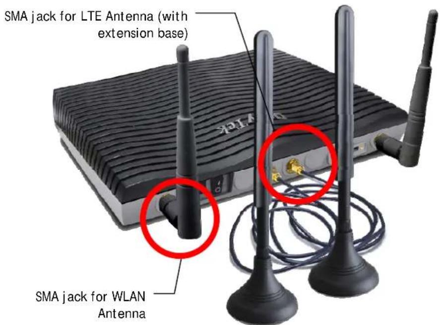
Magnetic antenna must be installed on the extension base before connecting to Vigor router.
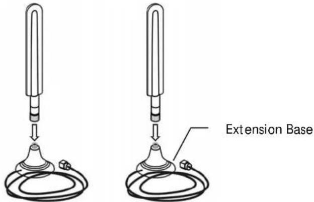
text_image
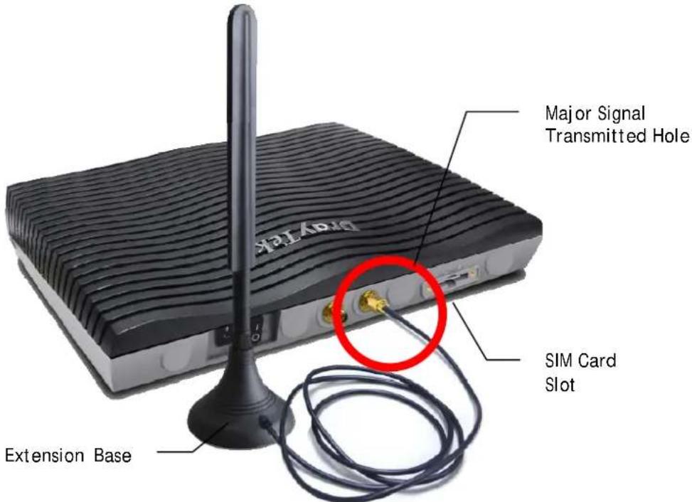
Extension BaseThere are two mounting holes for installing antennas with extension base on Vigor router. Please install them as shown below.
text_image
DRVTEK Major Signal Transmitted Hole SIM Card Slot Extension BaseNote, if only one antenna shall be installed, please use the mounting hole (major signal transmitted hole) near to the SIM card slot.
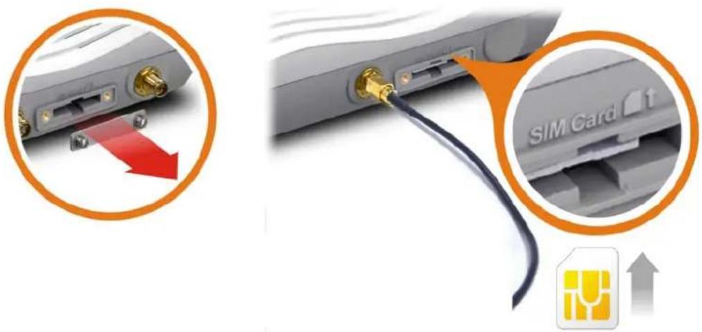
While installing the SIM card into the card slot, note that back plate of the SIM card slot must be removed first and the direction of card notch must be on the left side.
text_image
SIM Card ↑There are two types of antennas provided for Vigor2926Ln/ Vigor2926Lac, which must be installed in different locations carefully and correctly. Wrong installation might cause bad signal of wireless connection. Therefore, pay attention to the installation of antennas by referring to the following illustration.
text_image
SMA jack for LTE Antenna (with extension base) SMA jack for WLAN AntennaI-2 Hardware Installation
I-2-1 Installing Vigor Router
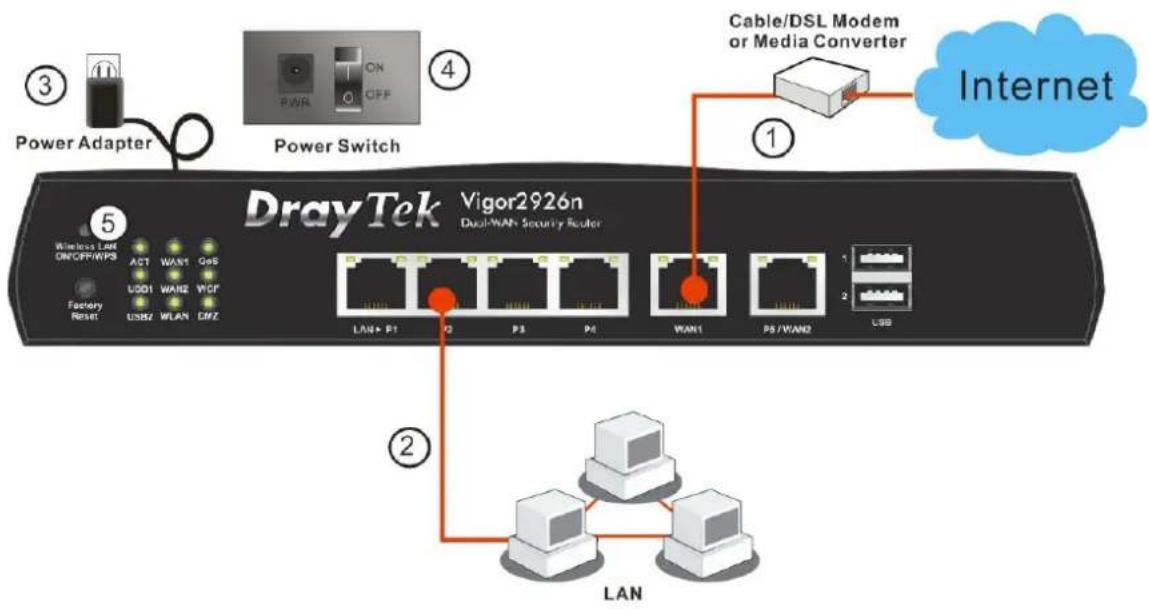
Before starting to configure the router, you have to connect your devices correctly. In this section, Vigor2926n is taken as an example.
- Connect the cable Modem/ DSL Modem/ Media Converter to any WAN port of router with Ethernet cable (RJ-45).
- Connect one end of an Ethernet cable (RJ-45) to one of the LAN ports of the router and the other end of the cable (RJ-45) into the Ethernet port on your computer.
- Connect one end of the power adapter to the router's power port on the rear panel, and the other side into a wall outlet.
- Power on the device by pressing down the power switch on the rear panel.
- The system starts to initiate. After completing the system test, the ACT LED will light up and start blinking.
text_image
Power Adapter Power Switch DrayTek Vigor2926n Dual-WAN Security Router ① Cable/DSL Modem or Media Converter Internet ② LAN ③ ④ ⑤ ⑥ ⑦ LAN+ P1 Q P3 P4 WAN1 P5/VAN2 USBI-2-2 Wall-Mounted Installation
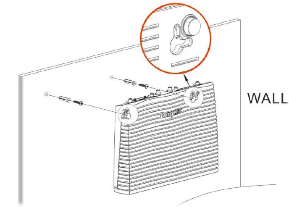
Vigor router has keyhole type mounting slots on the underside.
- A template is provided on the Vigor router packaging box to enable you to space the screws correctly on the wall.
- Place the template on the wall and drill the holes according to the recommended instruction.
- Fit screws into the wall using the appropriate type of wall plug.
text_image
WALL Dioxygen
Note
The recommended drill diameter shall be 6.5mm (1/4").
- When you finished about procedure, the router has been mounted on the wall firmly.
I-2-3 Installing USB Printer to Vigor Router
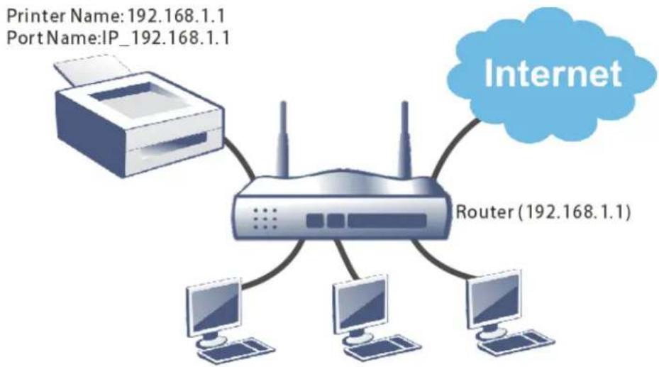
You can install a printer onto the router for sharing printing. All the PCs connected this router can print documents via the router. The example provided here is made based on Windows 7. For other Windows system, please visit www.DrayTek.com.
flowchart
graph TD
    A["Printer Name: 192.168.1.1\nPortName: IP_192.168.1.1"] --> B["Router (192.168.1.1)"]
    B --> C["Computer 1"]
    B --> D["Computer 2"]
    B --> E["Computer 3"]
    B --> F["Computer 4"]
    B --> G["Internet Cloud"]
Before using it, please follow the steps below to configure settings for connected computers (or wireless clients).
- Connect the printer with the router through USB/parallel port.
- Open All Programs>>Getting Started>>Devices and Printers.
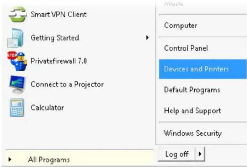
text_image
Smart VPN Client Getting Started Privatefirewall 7.0 Connect to a Projector Calculator All Programs Computer Control Panel Devices and Printers Default Programs Help and Support Windows Security Log off- Click Add a printer.
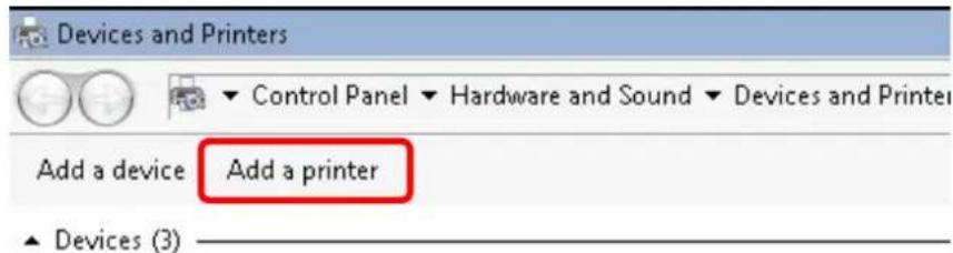
text_image
Devices and Printers Control Panel ▼ Hardware and Sound ▼ Devices and Printer Add a device Add a printer ▲ Devices (3)- A dialog will appear. Click Add a local printer and click Next.
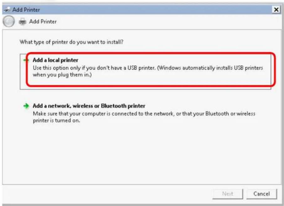
text_image
Add Printer What type of printer do you want to install? Add a local printer Use this option only if you don't have a USB printer. (Windows automatically installs USB printers when you plug them in.) Add a network, wireless or Bluetooth printer Make sure that your computer is connected to the network, or that your Bluetooth or wireless printer is turned on. Next Cancel- In this dialog, choose Create a new port. In the field of Type of port, use the drop down list to select Standard TCP/IP Port. Then, click Next.
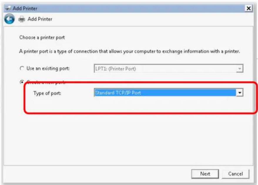
text_image
Add Printer Add Printer Choose a printer port A printer port is a type of connection that allows your computer to exchange information with a printer. Use an existing port: LPT1: (Printer Port) Create a print port Type of port: Standard TCP/IP Port Next Cancel- In the following dialog, type 192.168.1.1 (router's LAN IP) in the field of Hostname or IP Address and type 192.168.1.1 as the Port name. Then, click Next.
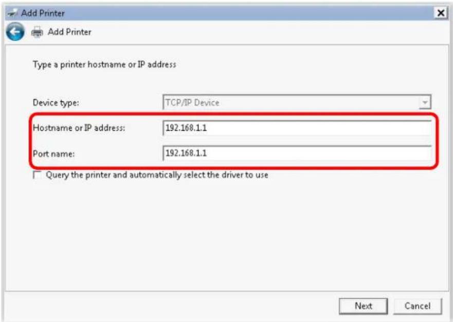
text_image
Add Printer Add Printer Type a printer hostname or IP address Device type: TCP/IP Device Hostname or IP address: 192.168.1.1 Port name: 192.168.1.1 Query the printer and automatically select the driver to use Next Cancel- Click Standard and choose Generic Network Card.
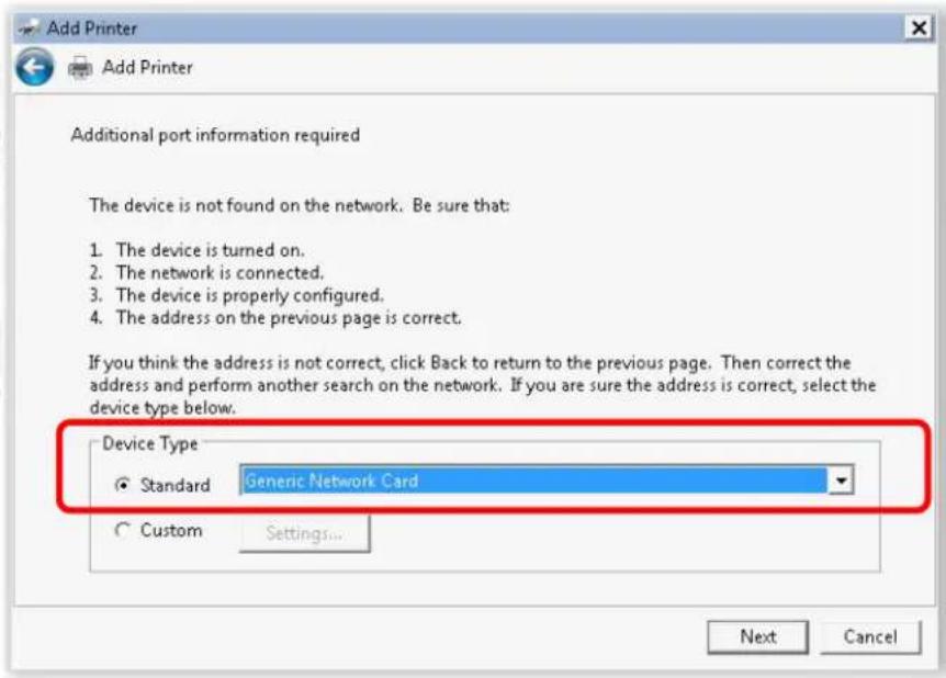
text_image
Add Printer Add Printer Additional port information required The device is not found on the network. Be sure that: 1. The device is turned on. 2. The network is connected. 3. The device is properly configured. 4. The address on the previous page is correct. If you think the address is not correct, click Back to return to the previous page. Then correct the address and perform another search on the network. If you are sure the address is correct, select the device type below. Device Type Standard Generic Network Card Custom Settings... Next Cancel- Now, your system will ask you to choose right name of the printer that you installed onto the router. Such step can make correct driver loaded onto your PC. When you finish the selection, click Next.
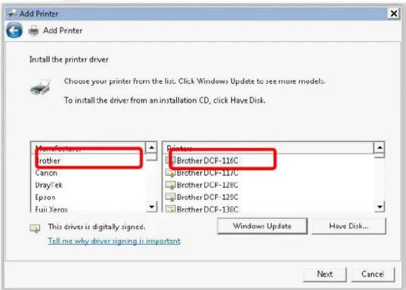
text_image
Add Printer Add Printer Install the printer driver Choose your printer from the list. Click Windows Update to see more models. To install the driver from an installation CD, click Have Disk. Manufacturer Brother Canon DrayTek Epson Fuii Xerox Printer Brother DCP-116C Brother DCP-117C Brother DCP-128C Brother DCP-129C Brother DCP-130C This driver is digitally signed. Tell me why driver signing is important Windows Update Have Disk... Next Cancel- Type a name for the chosen printer. Click Next.
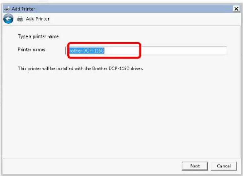
text_image
Add Printer Add Printer Type a printer name Printer name: Brother DCP-116C This printer will be installed with the Brother DCP-116C driver. Next Cancel- Choose Do not share this printer and click Next.
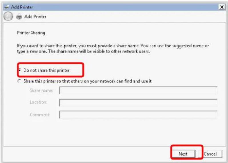
text_image
Add Printer Add Printer Printer Sharing If you want to share this printer, you must provide a share name. You can use the suggested name or type a new one. The share name will be visible to other network users. • Do not share this printer ○ Share this printer so that others on your network can find and use it Share name: Location: Comment: Next Cancel- Then, in the following dialog, click Finish.
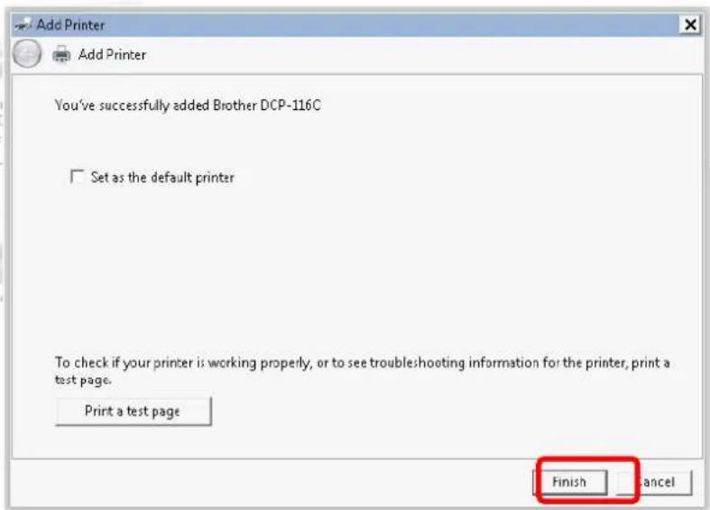
text_image
Add Printer Add Printer You've successfully added Brother DCP-116C Set as the default printer To check if your printer is working properly, or to see troubleshooting information for the printer, print a test page. Print a test page Finish Cancel- The new printer has been added and displayed under Printers and Faxes. Click the new printer icon and click Printer server properties.
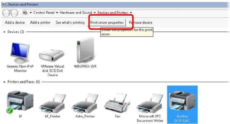
text_image
Devices and Printers Control Panel Hardware and Sound Devices and Printers Add a device Add a printer See what's printing Print server properties Remove device ▲ Devices (3) shows the properties for this print server. Generic Non-PnP Monitor VMware Virtual disk SCSI Disk Device WIN7PRO-SVR ▲ Printers and Faxes (5) 6F 6F_Printer Adm_Printer Fax Microsoft XPS Document Writer Brother DCP-116C- Edit the property of the new printer you have added by clicking Configure Port.
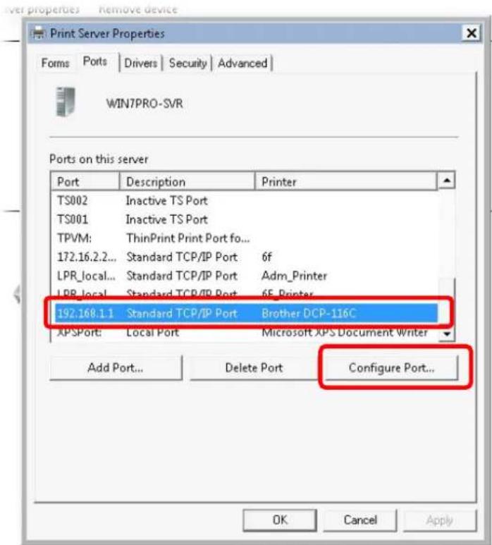
text_image
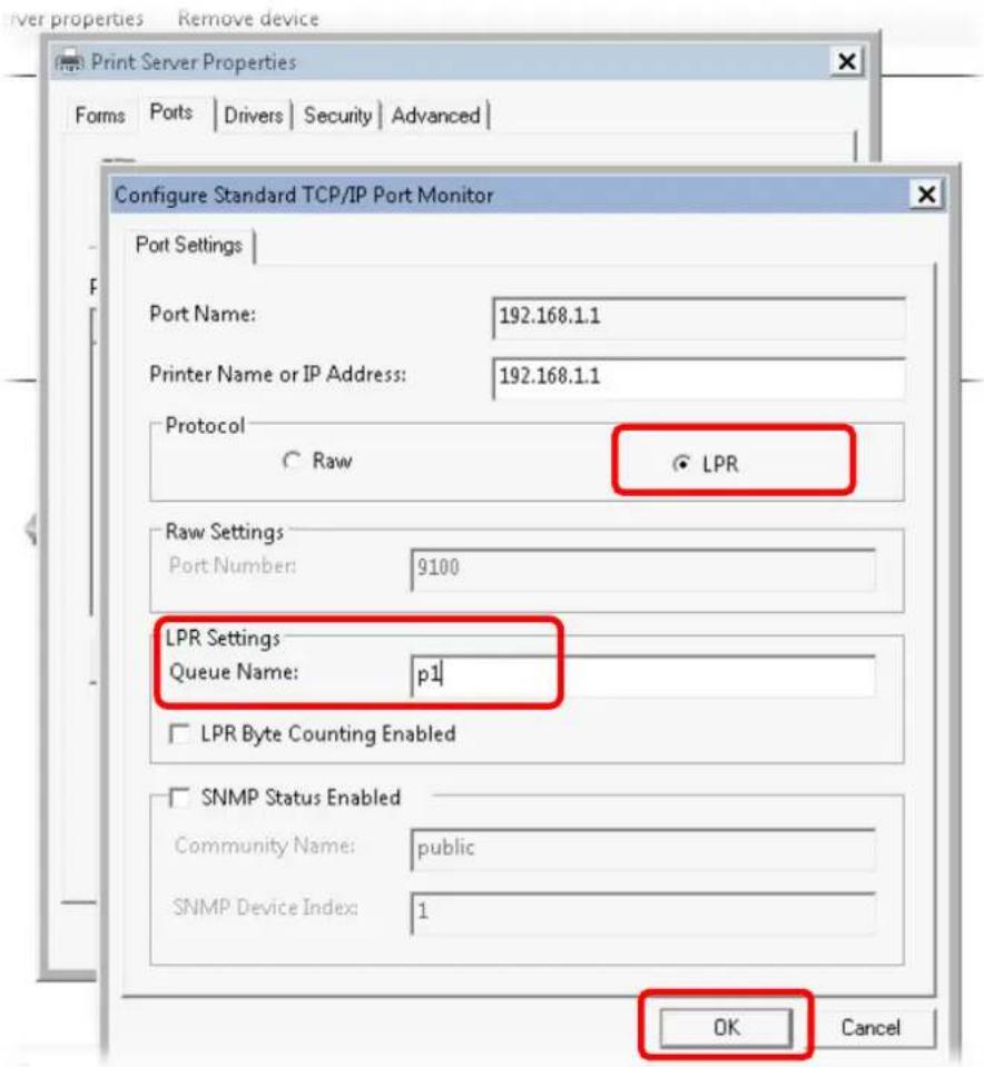
Print Server Properties Forms | Ports | Drivers | Security | Advanced | WIN7PRO-SVR Ports on this server Port Description Printer TS002 Inactive TS Port TS001 Inactive TS Port TPVM: ThinPrint Print Port fo... 172.16.2.2... Standard TCP/IP Port 6f LPR_local... Standard TCP/IP Port Adm Printer LPR_local... Standard TCP/IP Port 6F Printer 192.168.1.1 Standard TCP/IP Port Brother DCP-116C APSPort: Local Port Microsoft XPS Document Writer Add Port... Delete Port Configure Port... OK Cancel Apply- Select "LPR" on Protocol, type p1 (number 1) as Queue Name. Then click OK. Next please refer to the red rectangle for choosing the correct protocol and LPR name.
text_image
Printer properties Remove device Print Server Properties Forms Ports Drivers Security Advanced Configure Standard TCP/IP Port Monitor Port Settings Port Name: 192.168.1.1 Printer Name or IP Address: 192.168.1.1 Protocol Raw LPR Raw Settings Port Number: 9100 LPR Settings Queue Name: p1 LPR Byte Counting Enabled SNMP Status Enabled Community Name: public SNMP Device Index: 1 OK CancelThe printer can be used for printing now. Most of the printers with different manufacturers are compatible with vigor router.

Info
Some printers with the fax/scanning or other additional functions are not supported.
Vigor router supports printing request from computers via LAN ports but not WAN port.
I-3 Accessing Web Page
- Make sure your PC connects to the router correctly.
You may either simply set up your computer to get IP dynamically from the router or set up the IP address of the computer to be the same subnet as the default IP address of Vigor router 192.168.1.1. For the detailed information, please refer to the later section - Trouble Shooting of the guide.
- Open a web browser on your PC and type http://192.168.1.1. The following window will be open to ask for username and password.
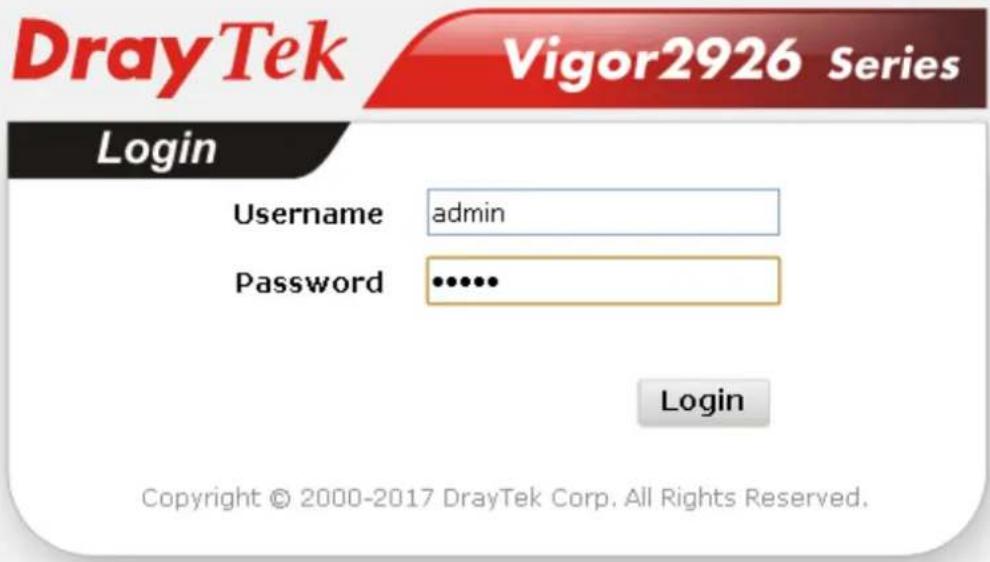
text_image
DrayTek Vigor2926 Series Login Username admin Password •••••• Login Copyright © 2000-2017 DrayTek Corp. All Rights Reserved.- Please type "admin/admin" as the Username/Password and click Login.

Info
If you fail to access to the web configuration, please go to "Trouble Shooting" for detecting and solving your problem.
- Now, the Main Screen will appear. Take Vigor2926Vac as as example.
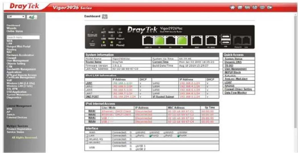
text_image
DrayTek Vigor2926 Series Dashboard DrayTek Vigor2926Vac System Information Model Name Vigor2026Vac System Up Time 66:31:46 Router Name DrayTek Current Time Mon Jan 03 2000 18:25:23 Firmware Version 2.9.1.1 Build Date/Time Aug 19 2019 15:29:37 LAN PAL Address 92-10-AA-99-87-C0 IPv4 LAN Information IP Address DHCP IP Address DHCP LAN1 192.168.1.1/24 v LAN2 192.168.2.1/24 v LAN3 192.168.3.1/24 v LAN4 192.168.4.1/24 v LAN5 192.168.5.1/24 v LAN6 192.168.6.1/24 v LAN7 192.168.7.1/24 v LAN8 192.168.8.1/24 v UMC PORT 192.168.2/4.1/24 v IP-Rated Subset 192.168.0.1/24 v IPv4 Internet Access Line / Mode IP Address MAC Address Up Time WANl Ethernet / DHCP Client Disconnected 90-1D-AA-69-87-C1 00:00:00 WANl Ethernet / DHCP Client Disconnected 90-1D-AA-69-87-C2 00:00:00 WANl USB --- Disconnected 90-1D-AA-69-87-C3 00:00:00 WANl USB --- Disconnected 90-1D-AA-69-87-C4 00:00:00 Interface WANl Connected: 0 WANl uWANl wWANl wWANl LAN Connected: 0 Port1 Port2 Port3 Port4 WANl/WANl/4G Connected: 0 WANl/WANlC Connected: 0 USB Connected: 0 USB 1 USB 0 USB 2
Info
The home page will be different slightly in accordance with the type of the router you have.
- The web page can be logged out according to the chosen condition. The default setting is Auto Logout, which means the web configuration system will logout after 5 minutes without any operation. Change the setting for your necessity.
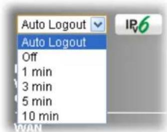
text_image
Auto Logout Auto Logout Off 1 min 3 min 5 min 10 min IPv6 WANI-4 Changing Password
Please change the password for the original security of the router.
- Open a web browser on your PC and type http://192.168.1.1. A pop-up window will open to ask for username and password.
- Please type "admin/admin" as Username/Password for accessing into the web user interface with admin mode.
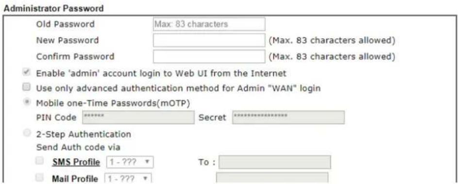
- Go to System Maintenance page and choose Administrator Password.
System Maintenance >> Administrator Password Setup
text_image
Administrator Password Old Password Max: 83 characters New Password (Max. 83 characters allowed) Confirm Password (Max. 83 characters allowed) ✓ Enable 'admin' account login to Web UI from the Internet ☐ Use only advanced authentication method for Admin "WAN" login ● Mobile one-Time Passwords(mOTP) PIN Code ***** Secret ********** ○ 2-Step Authentication Send Auth code via ☐ SMS Profile 1 - ??? To : ☐ Mail Profile 1 - ???- Enter the login password (the default is "admin") on the field of Old Password. Type New Password and Confirm Password. Then click OK to continue.

Info
The maximum length of the password you can set is 23 characters.
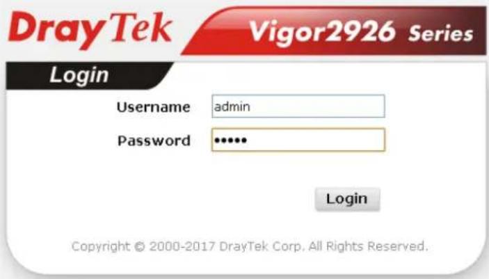
- Now, the password has been changed. Next time, use the new password to access the Web user interface for this router.
text_image
DrayTek Vigor2926 Series Login Username admin Password ••••• Login Copyright © 2000-2017 DrayTek Corp. All Rights Reserved.
Info
Even the password is changed, the Username for logging onto the web user interface is still "admin".
I-5 Dashboard
Dashboard shows the connection status including System Information, IPv4 Internet Access, IPv6 Internet Access, Interface (physical connection), Security and Quick Access.
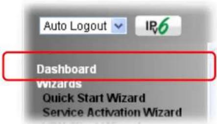
Click Dashboard from the main menu on the left side of the main page.
text_image
Auto Logout IP6 Dashboard Wizards Quick Start Wizard Service Activation WizardA web page with default selections will be displayed on the screen. Refer to the following figure:
Dashboard

text_image
DrayTek Vigor2926Vac DualWAN Security Router Wireless LAN CHINOPFAMPS ACT WAN1 Line USB WAN2 Phone1 Factory Reset 2.4G 5G Phone2 LAN+ P1 P2 P3 P4 WAN1 P5/PAN2 USB Phone12 Line| System Information | |||
| Model Name | Vigor2926Vac | System Up Time | 66:54:28 |
| Router Name | DrayTek | Current Time | Mon Jan 03 2000 18:54:05 |
| Firmware Version | 3.9.1.1 | Build Date/Time | Aug 19 2019 15:29:57 |
| LAN MAC Address | 00-1D-AA-69-87-C0 | ||
| IPv4 LAN Information | |||||
| IP Address | DHCP | IP Address | DHCP | ||
| LAN1 | 192.168.1.1/24 | v | LAN2 | 192.168.2.1/24 | v |
| LAN3 | 192.168.3.1/24 | v | LAN4 | 192.168.4.1/24 | v |
| LAN5 | 192.168.5.1/24 | v | LAN6 | 192.168.6.1/24 | v |
| LAN7 | 192.168.7.1/24 | v | LAN8 | 192.168.8.1/24 | v |
| DMZ PORT | 192.168.254.1/24 | v | IP Routed Subnet | 192.168.0.1/24 | v |
| Quick Access |
| System Status |
| Dynamic DNS |
| TR-069 |
| User Management |
| IMPZP Block |
| Schedule |
| SysLog / Mail Alert |
| LDAP |
| RADIUS |
| Firewall Object Setting |
| Data Flow Monitor |
| IPv4 Internet Access | ||||
| Line / Mode | IP Address | MAC Address | Up Time | |
| WAN1 | Ethernet / DHCP Client | Disconnected | 00-1D-AA-69-87-C1 | 00:00:00 |
| WAN2 | Ethernet / DHCP Client | Disconnected | 00-1D-AA-69-87-C2 | 00:00:00 |
| WAN3 | USB / --- | Disconnected | 00-1D-AA-69-87-C3 | 00:00:00 |
| WAN4 | USB / --- | Disconnected | 00-1D-AA-69-87-C4 | 00:00:00 |
| Interface | |||||
| WAN | Connected: 0, WAN1 WAN2 WAN3 WAN4 | ||||
| LAN | Connected: 0, Port1 Port2 Port3 Port4 | ||||
| WLAN2.4G | Connected: 0 | ||||
| WLAN5G | Connected: 0 | ||||
| USB | Connected: 0, USB 10, USB 2 | ||||
Security UON Connected - 0 Remote Dial In User / LAN to LAN
I-5-1 Virtual Panel
On the top of the Dashboard, a virtual panel (simulating the physical panel of the router) displays the physical interface connection. It will be refreshed every five seconds. When you move and click the mouse cursor on LEDs (except ACT), USB ports, WAN2, or LAN1 - LAN4, related web setting page will be open for you to configure if required.

text_image
DrayTek Vigor2926Vac Dual-WAN Security Router Wireless LAN ON/OFF/WPS ACT WAN1 Line USB WAN2 Phone1 Factory Reset 2.4G 5G Phone2 LAN P1 P2 P3 P4 WAN1 P5 / WAN2 USB Phone1/2 Line| Port Color | Description | |
| side) | Black It means the router or the function is not working. LED (left | |
| Green It means the router or the function is working. | ||
| Black It means no USB device is connected. USB | ||
| Green It means a USB device is connected. | ||
| Ethernet Port (WAN/ LAN) | Black It means such port is disconnected. | |
| Green It means such port is connected (with Giga transmission rate, 1Gbps) physically. | ||
| Orange It means such port is connected (with 10/100 Mbps) physically. | ||
For detailed information about the LED display, refer to I-1-1 LED Indicators and Connectors.
I-5-2 Name with a Link
A name with a link (e.g., Router Name, Current Time, WAN1\~3 and etc.) below means you can click it to open the configuration page for modification.
| System Information | |||
| Model Name | Vigor2926Vac | System Up Time | 66:54:28 |
| Router Name | DrayTek | Current Time | Mon Jan 03 2000 18:54:05 |
| Firmware Version | 3.9.1.1 | Build Date/Time | Aug 19 2019 15:29:57 |
| LAN MAC Address | 00-1D-AA-69-87-C0 | ||
| IPv4 LAN Information | |||||
| IP Address | DHCP | IP Address | DHCP | ||
| LAN1 | 192.168.1.1/24 | v | LAN2 | 192.168.2.1/24 | v |
| LAN3 | 192.168.3.1/24 | v | LAN4 | 192.168.4.1/24 | v |
| LAN5 | 192.168.5.1/24 | v | LAN6 | 192.168.6.1/24 | v |
| LAN7 | 192.168.7.1/24 | v | LAN8 | 192.168.8.1/24 | v |
| DMZ PORT | 192.168.254.1/24 | v | IP Routed Subnet | 192.168.0.1/24 | v |
I-5-3 Status for LTE
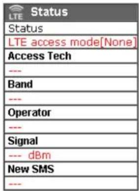
It is a short table which displays current status for Vigor2926L/ Vigor2926Ln including access mode used, access tech adopted, band usage, operator, strength of signal and notification of new SMS received.
text_image
Status LTE access mode[None] Access Tech --- Band --- Operator --- Signal --- dBm New SMS ---I-5-4 Quick Access for Common Used Menu
All the menu items can be accessed and arranged orderly on the left side of the main page for your request. However, some important and common used menu items which can be accessed in a quick way just for convenience.
Look at the right side of the Dashboard. You will find a group of common used functions grouped under Quick Access.
| Quick Access |
| System Status |
| Dynamic DNS |
| TR-069 |
| User Management |
| IM/P2P Block |
| Schedule |
| SysLog / Mail Alert |
| LDAP |
| RADIUS |
| Firewall Object Setting |
| Data Flow Monitor |
The function links of System Status, Dynamic DDNS, TR-069, User Management, IM/ P2P Block, Schedule, Syslog/ Mail Alert, LDAP, RADIUS, Firewall Object Setting and Data Flow Monitor are displayed here. Move your mouse cursor on any one of the links and click on it. The corresponding setting page will be open immediately.
In addition, quick access for VPN security settings such as Remote Dial-in User and LAN to LAN are located on the bottom of this page. Scroll down the page to find them and use them if required.

text_image
Interface WAN Connected: 0, WAN1 WAN2 WAN3 WAN4 LAN Connected: 0, Port1 Port2 Port3 Port4 WLAN2.4G Connected: 0 WLAN5G Connected: 0 USB Connected: 0, USB 1 0, USB 2 Security VPN Connected: 0 Remote Dial-in User / LAN to LAN MyVigor Activate: 0 DoS Attack Detected: System Resource Current Status CPU Usage: 2% Memory Usage: 53%Note that there is a plus ( ) icon located on the left side of LAN/ WLAN/ VPN/ MyVigor. Click it to review the LAN/ WLAN/ VPN/ MyVigor connection(s) used presently.
| Security | ||||
| VPN | Connected : 1 Remote Dial-in User / LAN to LAN | |||
| Current Page: 1 Page No. 1 Go To | ||||
| Name / User | Type / Security | Host IP | Up Time | |
| V2920 | IPsec/3DES | 172.16.2.145 | 0:0:20 | |
User Mode is OFF now.

text_image
LAN Connected : 1, LAN1 LAN2 LAN3 LAN4 LAN5 Host ID IP Address MAC CARRIE-0C7CB251 192.168.1.10 E0-CB-4E-DA-48-79 Connected : 0, USB 1Host connected physically to the router via LAN port(s) will be displayed with green circles in the field of Connected.
All of the hosts (including wireless clients) displayed with Host ID, IP Address and MAC address indicates that the traffic would be transmitted through LAN port(s) and then the WAN port. The purpose is to perform the traffic monitor of the host(s).
I-5-5 GUI Map

text_image
GUI MapAll the functions the router supports are listed with table clearly in this page. Users can click the function link to access into the setting page of the function for detailed configuration. Click the icon on the top of the main screen to display all the functions.
GUI Map
| Dashboard Wizards | Certificate Management | ||
| Quick Start Wizard | Local Certificate | ||
| Service Activation Wizard | Trusted CA Certificate | ||
| VPN Client Wizard | VoIP | Certificate Backup | |
| VPN Server Wizard | General Settings | ||
| Wireless Wizard | Wireless LAN(2.4GHz) | ||
| VoIP Wizard | General Setup | ||
| Online Status | Security | ||
| Physical Connection | Access Control | ||
| Virtual WAN | WPS | ||
| WAN | WDS | ||
| General Setup | Advanced Setting | ||
| Internet Access | Station Control | ||
| Multi-VLAN | Bandwidth Management | ||
| WAN Budget | AP Discovery | ||
| LAN | Airtime Fairness | ||
| General Setup | Band Steering | ||
| VLAN | Station List | ||
| Bind IP to MAC | Wireless LAN(5GHz) | ||
| LAN Port Mirror | General Setup | ||
| Wired 802.1X | Security | ||
| Hotspot Web Portal | Access Control | ||
| Profile Setup | WPS | ||
| Users Information | WDS | ||
| Routing | Advanced Setting |
I-5-6 Web Console
text_image
Web ConsoleIt is not necessary to use the telnet command via DOS prompt. The changes made by using web console have the same effects as modified through web user interface. The functions/settings modified under Web Console also can be reviewed on the web user interface.
Click the Web Console icon on the top of the main screen to open the following screen.
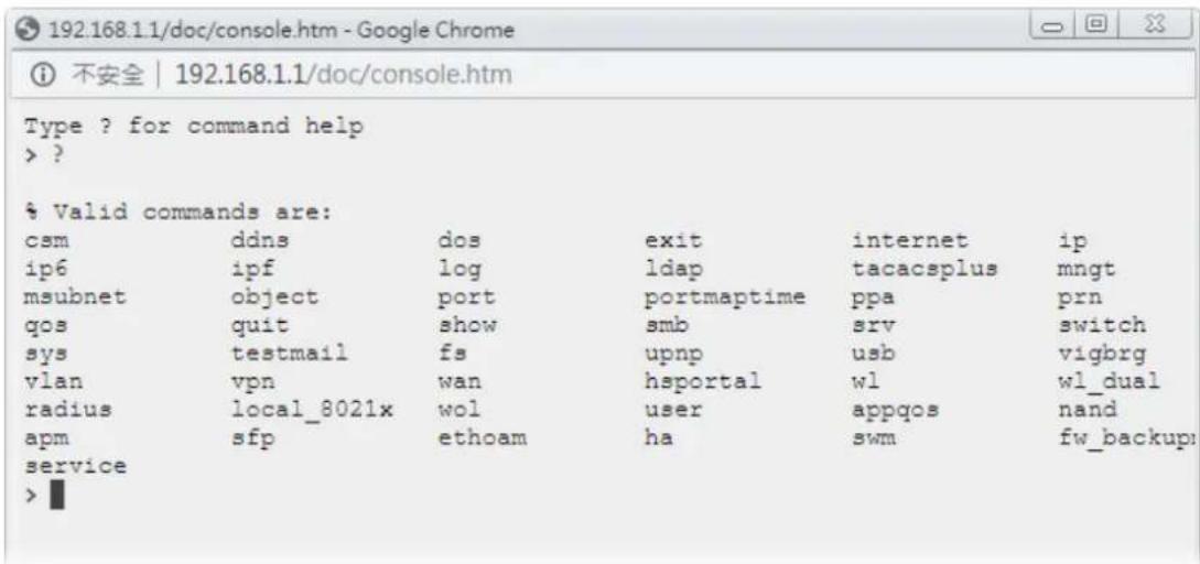
text_image
192.168.1.1/doc/console.htm - Google Chrome ① 不安全 | 192.168.1.1/doc/console.htm Type ? for command help > ? % Valid commands are: csm ddns dos exit internet ip ip6 ipf log ldap tacacsplus mngt msubnet object port portmaptime ppa prn qos quit show smb srv switch sys testmail fs upnp usb vigbrg vlan vpn wan hsportal wl wl_dual radius local_8021x wol user appqos nand apm sfp ethoam ha swm fw_backup service >I-5-7 Config Backup
text_image
Config BackupThere is one way to store current used settings quickly by clicking the Config Backup icon. It allows you to backup current settings as a file. Such configuration file can be restored by using System Maintenance>>Configuration Backup.
Simply click the icon on the top of the main screen and a pop up dialog will appear.
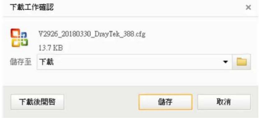
Click Save to store the setting.
I-5-8 Manual

text_image
Manual Downloadlick this icon to open online user's guide of Vigor router. This document offers detailed information for the settings on web user interface.
I-5-9 Logout
text_image
LogoutClick this icon to exit the web user interface.
I-5-10 Online Status
Online Status
Physical Connection
Virtual WAN
I-5-10-1 Physical Connection
Such page displays the physical connection status such as LAN connection status, WAN connection status, ADSL information, and so on.
Physical Connection for IPv4 Protocol
Online Status
| Physical Connection | System Uptime: 0day 2:12:14 | ||||
| IPv4 | IPv6 | ||||
| LAN Status | |||||
| IP Address | TX Packets | RX Packets | Router Primary DNS: | Router Secondary DNS: | |
| 192.108.1.1 | 22,291 | 15,+19 | 8.8.8.8 | 8.8.4.4 | |
| WAN 1 Status | >> Renew | ||||
| Enable | Line | Name | Mode | Up Time | |
| Yes | Ethernet | DHCP Client | 00:00:00 | ||
| IP | GW IP | TX Bytes | TX Rate(bps) | RX Bytes | RX Rate(bps) |
| --- | --- | 0 (B) | 0 | 0 (B) | 0 |
| WAN 2 Status | >> Renew | ||||
| Enable | Line | Name | Mode | Up Time | |
| Yes | Ethernet | DHCP Client | 00:00:00 | ||
| IP | GW IP | TX Bytes | TX Rate(bps) | RX Bytes | RX Rate(bps) |
| --- | --- | 0 (B) | 0 | 0 (B) | 0 |
| WAN 3 Status | |||||
| Enable | Line | Name | Mode | Up Time | Signal |
| Yes | USB | --- | 00:00:00 | - | |
| IP | GW IP | TX Bytes | TX Rate(bps) | RX Bytes | RX Rate(bps) |
| --- | --- | 0 (B) | 0 | 0 (B) | 0 |
| WAN 4 Status | |||||
| Enable | Line | Name | Mode | Up Time | Signal |
| Yes | USB | --- | 00:00:00 | - | |
| IP | GW IP | TX Bytes | TX Rate(bps) | RX Bytes | RX Rate(bps) |
| --- | --- | 0 | 0 | 0 | 0 |
LTE WAN
Online Status
Physical Connection

System Uptime: 0day 0:14:1
| IPv4 | IPv6 | ||||
| LAN Status | |||||
| IP Address | TX Packets | RX Packets | Router Primary DNS: | Router Secondary DNS: | |
| 192.168.1.1 | 22,001 | 24,265 | 168.95.1.1 | 8.8.8.8 | |
| WAN 1 Status | >> Release | ||||
| Enable | Line | Name | Mode | Up Time | |
| Yes | Ethernet | DHCP Client | 0:13:11 | ||
| IP | GW IP | TX Bytes | TX Rate(bps) | RX Bytes | RX Rate(bps) |
| 192.168.39.19 | 192.168.39.1 | 733 (KB) | 2.01 K | 1117 (KB) | 2.38 K |
| WAN 2 Status | >> Renew | ||||
| Enable | Line | Name | Mode | Up Time | |
| Yes | Ethernet | DHCP Client | 00:00:00 | ||
| IP | GW IP | TX Bytes | TX Rate(bps) | RX Bytes | RX Rate(bps) |
| --- | --- | 0 (B) | 0 | 0 (B) | 0 |
| LTE Status | >> Release | ||||
| Enable | Line | Name | Mode | Up Time | |
| Yes | USB | DHCP Client | 0:00:02 | ||
| IP | GW IP | TX Bytes | TX Rate(bps) | RX Bytes | RX Rate(bps) |
| 10.70.104.102 | 10.70.104.101 | 0 (B) | 0 | 654 (B) | 488 |
| USB Modem | Status | Base Station ID | Signal Strength(RSSI) | Signal Quality(CINR) | >> Restart |
| Device Exists | Operational 00:A0:C6:00:01:55 -38 dBm | 62 dB(99%) | NetWork Mode4G/3G/2G | ||
| WAN 4 Status | |||||
| Enable | Line | Name | Mode | Up Time | Signal |
| Yes | USB | --- | 00:00:00 | ||
| IP | GW IP | TX Bytes | TX Rate(bps) | RX Bytes | RX Rate(bps) |
| --- | --- | 0 | 0 | 0 | 0 |
Physical Connection for IPv6 Protocol
Online Status
| Physical Connection | System Uptime: 0day 0:0:52 | |||
| IPv4 | IPv6 | |||
| LAN Status | ||||
| IP Address | ||||
| 2001:388:E001:9501:21D:AAFF:FECA:7700/64 (Global) | ||||
| FE80::21D:AAFF:FECA:7700/64 (Link) | ||||
| TX Packets | RX Packets | TX Bytes | RX Bytes | |
| 17 | 76 | 1,766 | 23,236 | |
| WAN1 IPv6 Status | ||||
| Enable | Mode | Up Time | ||
| Yes | TSPC | 0:00:29 | ||
| IP | Gateway IP | |||
| 2001:388:F000::2EF3/128 (Global) | --- | |||
| FE80::C0A8:30A/128 (Link) | ||||
| TX Packets | RX Packets | TX Bytes | RX Bytes | |
| 10 | 39 | 760 | 9,143 | |
| WAN2 IPv6 Status | ||||
| Enable | Mode | Up Time | ||
| No | Offline | --- | ||
| IP | Gateway IP | |||
| --- | --- | |||
| WAN3 IPv6 Status | ||||
| Enable | Mode | Up Time | ||
| No | Offline | --- | ||
| IP | Gateway IP | |||
| --- | --- | |||
| WAN4 IPv6 Status | ||||
| Enable | Mode | Up Time | ||
| No | Offline | --- | ||
| IP | Gateway IP | |||
| --- | --- | |||
Detailed explanation (for IPv4) is shown below:
| Item | Description |
| LAN Status Primary DNS-Displays the primary DNS server address for WAN interface.Secondary DNS -Displays the secondary DNS server address for WAN interface.IP Address-Displays the IP address of the LAN interface.TX Packets-Displays the total transmitted packets at the LAN interface.RX Packets-Displays the total received packets at the LAN interface. | |
| WAN1/WAN2/WAN3 /WAN4 Status | Enable - Yes in red means such interface is available but not enabled. Yes in green means such interface is enabled.Line - Displays the physical connection (VDSL, ADSL, Ethernet, or USB) of this interface.Name - Display the name of the router.Mode - Displays the type of WAN connection (e.g., PPPoE).Up Time - Displays the total uptime of the interface.IP - Displays the IP address of the WAN interface.GW IP - Displays the IP address of the default gateway.TX Packets - Displays the total transmitted packets at the WAN interface.TX Rate - Displays the speed of transmitted octets at the WAN interface.RX Packets - Displays the total number of received packets at the WAN interface.RX Rate - Displays the speed of received octets at the WAN interface. |
Detailed explanation (for IPv6) is shown below:
| Item | Description |
| LAN Status | IP Address- Displays the IPv6 address of the LAN interface..TX Packets-Displays the total transmitted packets at the LAN interface.RX Packets-Displays the total received packets at the LAN interface.TX Bytes - Displays the speed of transmitted octets at the LAN interface.RX Bytes - Displays the speed of received octets at the LAN interface. |
| WAN IPv6 Status Enable - No | in red means such interface is available but not enabled.Yes in green means such interface is enabled. No in red means such interface is not available.Mode - Displays the type of WAN connection (e.g., TSPC).Up Time - Displays the total uptime of the interface.IP - Displays the IP address of the WAN interface.Gateway IP - Displays the IP address of the default gateway. |

Info
The words in green mean that the WAN connection of that interface is ready for accessing Internet; the words in red mean that the WAN connection of that interface is not ready for accessing Internet.
I-5-10-2 Virtual WAN
Such page displays the virtual WAN connection information.
Virtual WAN are used by TR-069 management, VoIP service and so on.
The field of Application will list the purpose of such WAN connection.
I-6 Quick Start Wizard
Quick Start Wizard can help you to deploy and use the router easily and quickly. Go to Wizards>>Quick Start Wizard. The first screen of Quick Start Wizard is entering login password. After typing the password, please click Next.
Quick Start Wizard
Enter login password
Please enter an alpha-numeric string as your Password.
Old Password
New Password
Confirm Password
Max 23 characters
Hint: If you want to keep the password unchanged, leave the password blank and press "Next" button to skip this process.

On the next page as shown below, please select the WAN interface that you use. If Ethernet interface is used, please choose WAN1/WAN2; if 3G/4G USB modem is used, please choose WAN3/WAN4; if LTE SIM card is used, please choose LTE.. Then click Next for next step.
Quick Start Wizard
WAN Interface
WAN Interface:
Display Name:
Physical Mode:
Physical Type:
WAN1
Ethernet
Auto negotiation

WAN1, WAN2, WAN3/LTE and WAN4 will bring up different configuration page. Refer to the following for detailed information. In which, WAN3 will be treated as USB WAN or LTE WAN according to the USB modem or SIM Card used for accessing Internet.
I-6-1 For WAN1/WAN2 (Ethernet)
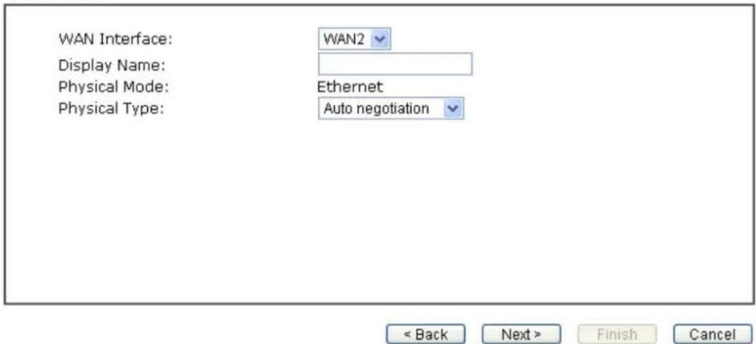
WAN1/WAN2 is dedicated to physical mode in Ethernet. If you choose WAN1/WAN2, please specify physical type. Then, click Next.
Quick Start Wizard
WAN Interface
text_image
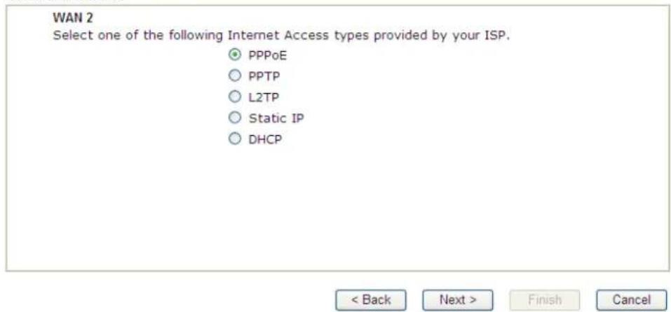
WAN Interface: Display Name: Physical Mode: Physical Type: WAN2 Ethernet Auto negotiation < Back Next > Finish CancelOn the next page as shown below, please select the appropriate Internet access type according to the information from your ISP. For example, you should select PPPoE mode if the ISP provides you PPPoE interface. Then click Next for next step.
PPPoE
- Choose WAN1/WAN2 as the WAN Interface and click the Next button. The following page will be open for you to specify Internet Access Type.
Quick Start Wizard
Connect to Internet
text_image
WAN 2 Select one of the following Internet Access types provided by your ISP. ● PPPoE ○ PPTP ○ L2TP ○ Static IP ○ DHCP < Back Next > Finish Cancel- Click PPPoE as the Internet Access Type. Then click Next to continue.
Quick Start Wizard
PPPoE Client Mode
WAN 2
Enter the user name and password provided by your ISP.
Service Name (Optional)
CHT
Username
84005657@hinet.net
Password
■■■■■■
Confirm Password
■■■■■

Available settings are explained as follows:
| Item | Description |
| Service Name(Optional) | Enter the description of the specific network service. |
| Username Assign a sp | specific valid user name provided by the ISP.Note: The maximum length of the user name you can set is 63 characters. |
| Password Assign a valid password provided by the ISP.Note: The maximum length of the password you can set is 62 characters. | |
| Confirm Password Retype the password. | |
| Back Click it to return to previous setting page. | |
| Next Click it to get into the next setting page. | |
| Cancel Click it to give up the quick start wizard. | |
- Please manually enter the Username/ Password provided by your ISP. Click Next for viewing summary of such connection.
Quick Start Wizard
Please confirm your settings:
WAN Interface:
WAN2
Physical Mode:
Ethernet
Physical Type:
Auto negotiation
Internet Access:
PPPoE
Click Back to modify changes if necessary. Otherwise, click Finish to save the current settings and restart the Vigor router.
< Back
Next>
Finish
Cancel
- Click Finish. A page of Quick Start Wizard Setup OK!!! will appear. Then, the system status of this protocol will be shown.
Quick Start Wizard Setup OK!
- Now, you can enjoy surfing on the Internet.
PPTP/L2TP
- Choose WAN1/WAN2 as the WAN Interface and click the Next button. The following page will be open for you to specify Internet Access Type.
Quick Start Wizard
Connect to Internet
WAN 1
Select one of the following Internet Access types provided by your ISP.
PPPoE
PPTP
L2TP
Static IP
DHCP
< Back
Next>
Finish
Cancel
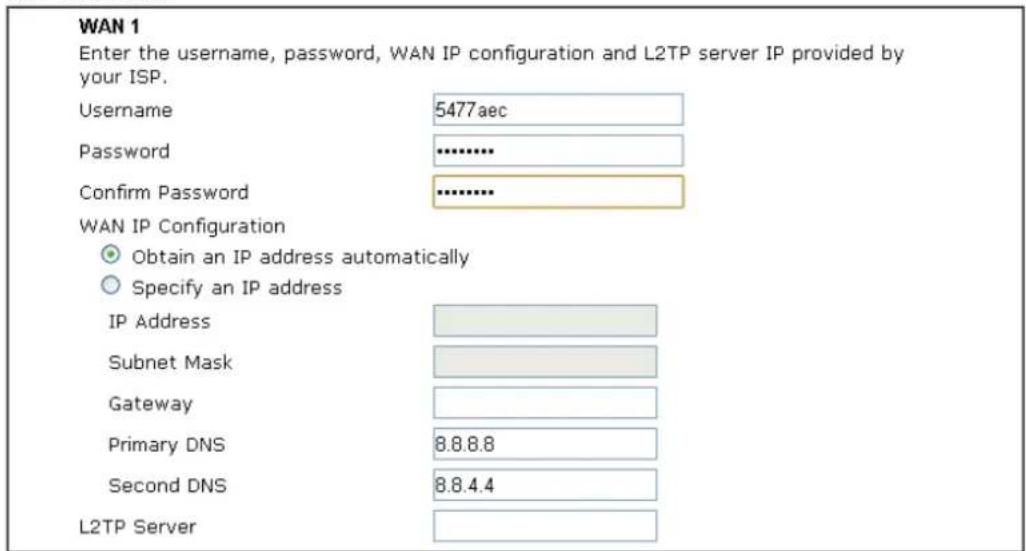
- Click PPTP/L2TP as the Internet Access Type. Then click Next to continue.
Quick Start Wizard
L2TP Client Mode
text_image
WAN 1 Enter the username, password, WAN IP configuration and L2TP server IP provided by your ISP. Username 5477aec Password .......... Confirm Password .......... WAN IP Configuration Obtain an IP address automatically Specify an IP address IP Address Subnet Mask Gateway Primary DNS 8.8.8.8 Second DNS 8.8.4.4 L2TP Server< Back
Next >
Finish
Cancel
Available settings are explained as follows:
| Item | Description |
| Username Assign a specific valid user name provided by the ISP.Note: The maximum length of the user name you can set is 63 characters. | |
| Password Assign a valid password provided by the ISP.Note: The maximum length of the password you can set is 62 | |
| characters. | |
| Confirm Password Retype the password. | |
| WAN IP Configuration | Obtain an IP address automatically - the router will get an IP address automatically from DHCP server.Specify an IP address - you have to type relational settings manually.IP Address - Enter the IP address.Subnet Mask -Enter the subnet mask.Gateway - Enter the IP address of the gateway.Primary DNS / Second DNS - Enter the IP address of the DNS server. |
| PPTP Server / L2TP Server | Enter the IP address of the server. |
| Back Click it to return to previous setting page. | |
| Next Click it to get into the next setting page. | |
| Cancel Click it to give up the quick start wizard. | |
- Please type in the IP address/ mask/ gateway information originally provided by your ISP. Then click Next for viewing summary of such connection.
Quick Start Wizard
Please confirm your settings:
WAN Interface:
WAN1
Physical Mode:
Ethernet
Physical Type:
Auto negotiation
Internet Access:
L2TP
Click Back to modify changes if necessary. Otherwise, click Finish to save the current settings and restart the Vigor router.
< Back Next > Finish Cancel
- Click Finish. A page of Quick Start Wizard Setup OK!!! will appear. Then, the system status of this protocol will be shown.
Quick Start Wizard Setup OK!
- Now, you can enjoy surfing on the Internet.
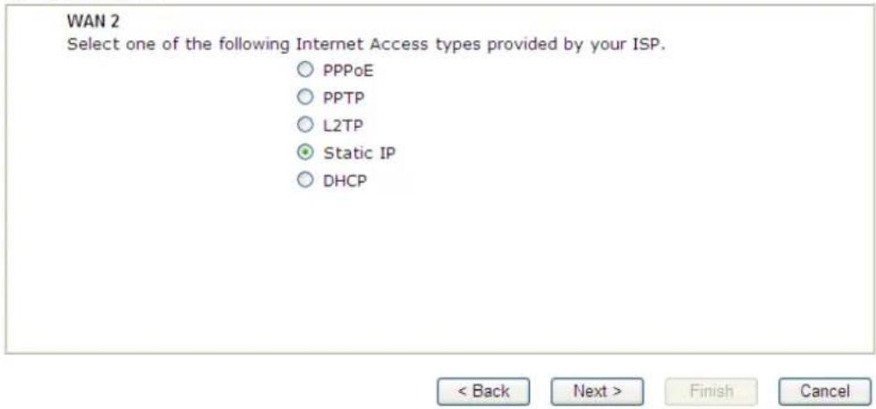
Static IP
- Choose WAN1/WAN2 as the WAN Interface and click the Next button. The following page will be open for you to specify Internet Access Type.
Quick Start Wizard
Connect to Internet
text_image
WAN 2 Select one of the following Internet Access types provided by your ISP. ○ PPPoE ○ PPTP ○ L2TP ● Static IP ○ DHCP < Back Next > Finish Cancel- Click Static IP as the Internet Access type. Simply click Next to continue.
Quick Start Wizard
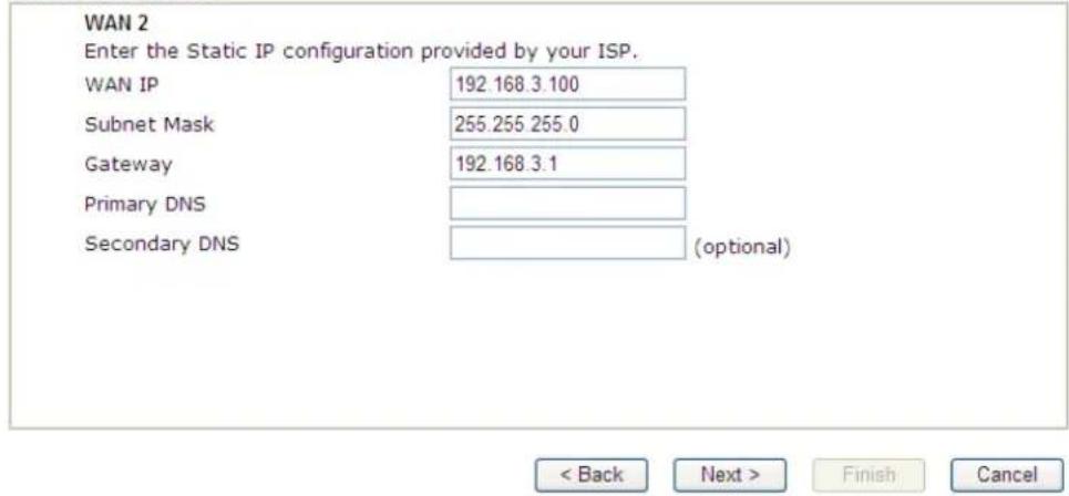
Static IP Client Mode
text_image
WAN 2 Enter the Static IP configuration provided by your ISP. WAN IP 192.168.3.100 Subnet Mask 255.255.255.0 Gateway 192.168.3.1 Primary DNS Secondary DNS (optional) < Back Next > Finish CancelAvailable settings are explained as follows:
| Item | Description |
| WAN IP Enter the IP address. | |
| Subnet Mask Enter the subnet mask. | |
| Gateway Enter the IP address of gateway. | |
| Primary DNS Type in the primary IP address for the router. | |
| Secondary DNS Type in secondary IP address for necessity in the future. | |
| Back Click it to return to previous setting page. | |
| Next Click it to get into the next setting page. | |
Cancel Click it to give up the quick start wizard.
- Please type in the IP address information originally provided by your ISP. Then click Next for next step.
Quick Start Wizard
Please confirm your settings:
WAN Interface:
WAN2
Physical Mode:
Ethernet
Physical Type:
Auto negotiation
Internet Access:
Static IP
Click Back to modify changes if necessary. Otherwise, click Finish to save the current settings and restart the Vigor router.

- Click Finish. A page of Quick Start Wizard Setup OK!!! will appear. Then, the system status of this protocol will be shown.
Quick Start Wizard Setup OK!
- Now, you can enjoy surfing on the Internet.
DHCP
- Choose WAN2 as the WAN Interface and choose Ethernet as the Physical Mode. Click the Next button. The following page will be open for you to specify Internet Access Type.
Quick Start Wizard
Connect to Internet
WAN 2
Select one of the following Internet Access types provided by your ISP.
○ PPPoE
○ PPTP
L2TP
Static IP
DHCP

- Click DHCP as the Internet Access type. Simply click Next to continue.
DHCP Client Mode
WAN 2 If your ISP requires you to enter a specific host name or specific MAC address, please enter it in.
Host Name
MAC

< Back
Next >
Finish
Cancel
Available settings are explained as follows:
| Item | Description |
| Host Name Enter the name of the host. Note: The maximum length of the host name you can set is 39 characters. | |
| MAC Some Cable service providers specify a specific MAC address for access authentication. In such cases you need to enter the MAC address. | |
| Back Click it to return to previous setting page. | |
| Next Click it to get into the next setting page. | |
| Cancel Click it to give up the quick start wizard. | |
- After finished the settings above, click Next for viewing summary of such connection.
Quick Start Wizard
Please confirm your settings:
WAN Interface:
Physical Mode:
Physical Type:
Internet Access:
WAN2
Ethernet
Auto negotiation
DHCP
Click Back to modify changes if necessary. Otherwise, click Finish to save the current settings and restart the Vigor router.
< Back
Next>
Finish
Cancel
- Click Finish. A page of Quick Start Wizard Setup OK!!! will appear. Then, the system status of this protocol will be shown.
Quick Start Wizard Setup OK!
- Now, you can enjoy surfing on the Internet.
I-6-2 For WAN3/WAN4 (USB)
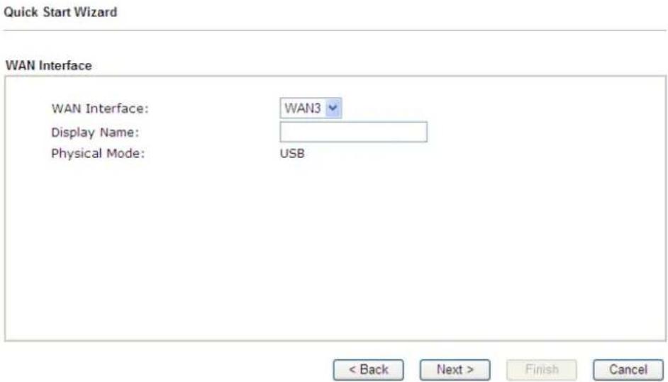
WAN3/ WAN4 is dedicated to physical mode in USB.
- Choose WAN3/WAN4 as WAN Interface.
text_image
Quick Start Wizard WAN Interface WAN Interface: WAN3 Display Name: Physical Mode: USB < Back Next > Finish Cancel- Then, click Next for getting the following page.
Quick Start Wizard
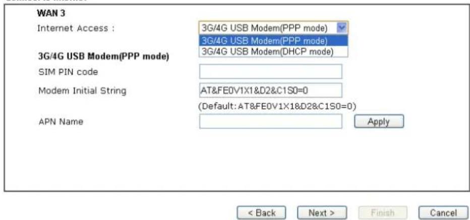
Connect to Internet
text_image
WAN 3 Internet Access : 3G/4G USB Modem(PPP mode) 3G/4G USB Modem(PPP mode) 3G/4G USB Modem(DHCP mode) 3G/4G USB Modem(PPP mode) SIM PIN code Modem Initial String AT&FE0V1X1&D2&C1S0=0 (Default: AT&FE0V1X1&D2&C1S0=0) APN Name Apply < Back Next > Finish CancelAvailable settings are explained as follows:
| Item | Description |
| Internet Access Choose | one of the selections as the protocol of accessing the internet. |
| 3G/4G USB Modem (PPP mode) | SIM Pin code -Type PIN code of the SIM card that will be used to access Internet. The maximum length of the pin code you can set is 15 characters.Modem Initial String - Such value is used to initialize USB modem. Please use the default value. If you have any question, please contact to your ISP. The maximum length of the string you can set is 47 characters.APN Name - APN means Access Point Name which is provided and required by some ISPs. Enter the name and click Apply. |
| 3G/4G USB Modem (DHCP mode) | SIM Pin code - Type PIN code of the SIM card that will be used to access Internet.Network Mode - Force Vigor router to connect Internet with the mode specified here. If you choose 4G/ 3G/ 2G as network mode, the router will choose a suitable one according to the actual wireless signal automatically.APN Name - APN means Access Point Name which is provided and required by some ISPs. |
- Then, click Next for viewing summary of such connection.
Quick Start Wizard
Please confirm your settings:
| WAN Interface: | WAN3 |
| Physical Mode: | USB |
| Internet Access: | PPP |
Click Back to modify changes if necessary. Otherwise, click Finish to save the current settings and restart the Vigor router.

- Click Finish. A page of Quick Start Wizard Setup OK!!! will appear. Then, the system status of this protocol will be shown.
Quick Start Wizard Setup OK!
- Now, you can enjoy surfing on the Internet.
I-6-3 For LTE WAN
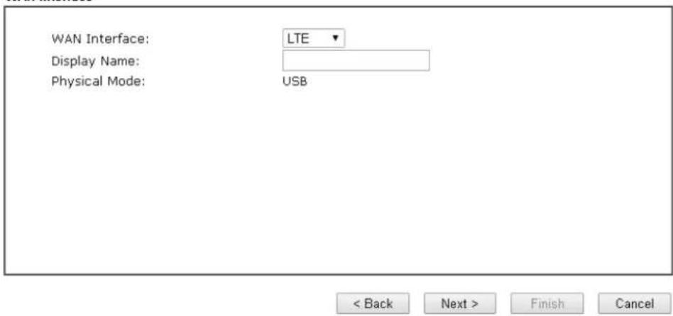
- Choose LTE as WAN Interface.
Quick Start Wizard
WAN Interface
text_image
WAN Interface: Display Name: Physical Mode: LTE USB < Back Next > Finish Cancel- Then, click Next for getting the following page.
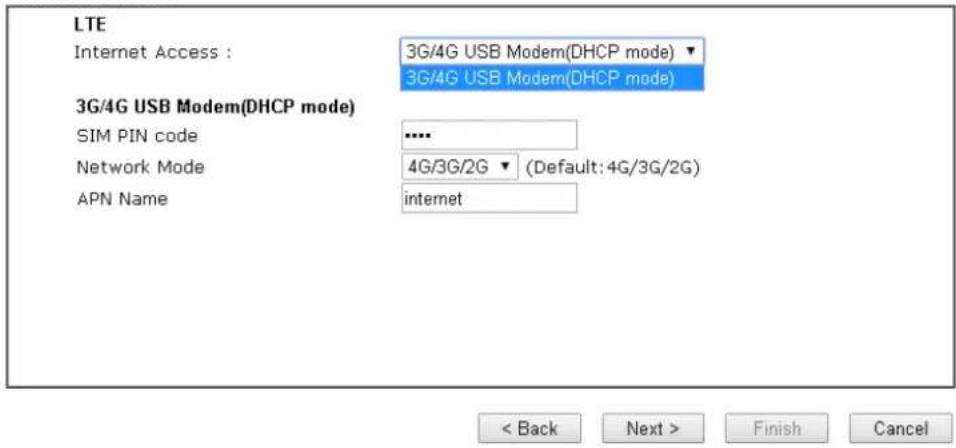
Quick Start Wizard
Connect to Internet
text_image
LTE Internet Access : 3G/4G USB Modem(DHCP mode) 3G/4G USB Modem(DHCP mode) 3G/4G USB Modem(DHCP mode) SIM PIN code .... Network Mode 4G/3G/2G (Default: 4G/3G/2G) APN Name internet < Back Next > Finish CancelAvailable settings are explained as follows:
| Item | Description |
| Internet Access Now, DHCP mode is the only choice for LTE WAN. | |
| 3G/4G USB Modem (DHCP mode) | SIM Pin code - Type PIN code of the SIM card that will be used to access Internet.Network Mode - Force Vigor router to connect Internet with the mode specified here. If you choose 4G/ 3G/ 2G as network mode, the router will choose a suitable one according to the actual wireless signal automatically.APN Name - APN means Access Point Name which is provided and required by some ISPs. |
- Please type in required information originally provided by your ISP. Then, click Next for viewing summary of such connection.
Quick Start Wizard
Please confirm your settings:
WAN Interface: LTE
Physical Mode: USB
Internet Access: DHCP
Click Back to modify changes if necessary. Otherwise, click Finish to save the current settings and restart the Vigor router.

- Click Finish. A page of Quick Start Wizard Setup OK!!! will appear. Then, the system status of this protocol will be shown.
Quick Start Wizard Setup OK!
- Now, you can enjoy surfing on the Internet.
I-7 Service Activation Wizard
Service Activation Wizard can guide you to activate WCF service (Web Content Filter) with a quick and easy way. For the Service Activation Wizard is only available for admin operation, therefore, please type “admin/admin” on Username/Password while Logging into the web user interface.
Service Activation Wizard is a tool which allows you to use trial version of WCF directly without accessing into the server (MyVigor) located on http://myvigor.draytek.com. For using Web Content Filter Profile, please refer to later section Web Content Filter Profile for detailed information.
Now, follow the steps listed below to activate WCF feature for your router.

Info
Such function is available only for Admin Mode.
- Open Wizards>>Service Activation Wizard.
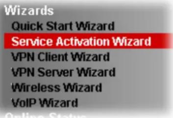
text_image
Wizards Quick Start Wizard Service Activation Wizard VPN Client Wizard VPN Server Wizard Wireless Wizard VoIP Wizard- In the following page, you can activate the Web content filter services and APP Enforcement service at the same time or individually. When you finish the selection, please click Next.
Select the service type that you want to activate
Web Content Filter(WCF) Service :
BPJM
License Agreement
This is a web content filter that is provided by the German government. It is a free service without any guarantee and will expire one year after activation. You may re-activate the service after expiry.
Cyron 30-Days Free Trial
License Agreement
This is a worldwide web content filter service. The free trail license can only be used once. At the end of the free trail period you may purchase the official one-year Cyren Web Content Filter from an authorized DrayTek reseller.
APP Enforcement(APPE) Service :
DT-APPE
License Agreement
Upgrade APPE Signature automatically.
Dynamic DNS(DDNS) Service
DT-DDNS
License Agreement
This Dynamic Domain Name service is provided by DrayTek Corporation. To active the DrayDDNS (Global) service, please select this option to active the license. This is a 1-year free license key. For re-activation after expiry, you have to obtain a new license from MyVigor website (https://myvigor.draytek.com).
I agree to let the MyVigor server record the WAN or Internet IP address of this router in order to activate the DrayDDNS service. You can stop this service and clear your IP address at any time.
Domain Name : 2019012111045601 ,drayddns.com
I have read and accept the above Agreement. (Please check this box).
Next > Cancel

Info
BPjM is web content filter (WCF) for German Speaking users. It is ideal for your family to provide more Internet security for youngsters.
Cryan 30-day trial is WCF which offers 30-day trial period. After trial, you can purchase DrayTek's prepared Cryan GlobalView WCF package from retailing outlets.
DT-APPE, developed by DrayTek, offers a mechanism to upgrade APPE signature automatically.
DT-DDNS, developed by DrayTek, offers one year free charge service of dynamic DNS service for internal use.
- Setting confirmation page will be displayed as follows, please click Activate.
Service Activation Wizard
Please confirm your settings
Sevice Type : Trial version Sevice Activated : Web Content Filter (Cyren / Commtouch) APP Enforcement (DT-APPE) Please click Back to re-select service type you to activate.


Info
The service will be activated and applied as the default rule configured in Firewall>>General Setup.
- Now, the web page will display the service that you have activated according to your selection(s). The valid time for the free trial of these services is one month.
DrayTek Service Activation
| Service Name | Start Date | Expire Date | Status |
| Web Content filter | --- | --- | Not Activated |
| APP Enforcement | 2017-08-14 | 2018-08-14 | DT-APPE |
| DDNS | |||
Please check if the license fits with the service provider of your signature. To ensure normal operation for your router, update your signature again is recommended.
I-8 MyVigor Services
I-8-1 Registering Vigor Router
You have finished the configuration of Quick Start Wizard and you can surf the Internet at any time. Now it is the time to register your Vigor router to MyVigor website for getting more service. Please follow the steps below to finish the router registration.
- Please login the web configuration interface of Vigor router by typing "admin/admin" as User Name / Password.
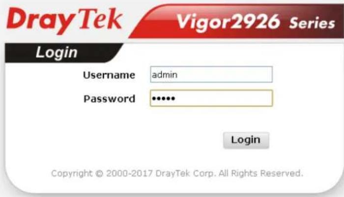
text_image
DrayTek Vigor2926 Series Login Username admin Password •••••• Login Copyright © 2000-2017 DrayTek Corp. All Rights Reserved.- Click Support Area>>Production Registration from the home page.
Support Area Product Registration
- A Login page will be shown on the screen. Please type the account and password that you created previously. And click Login.
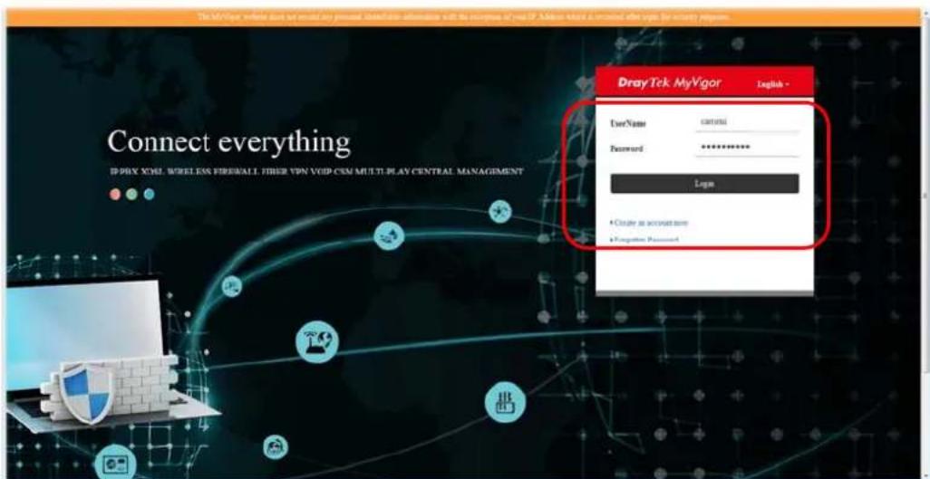
text_image
DrayTek MyVigor English - Connect everything ID:PHY XML, WIRELXX FISERWALL, OTHER VPN VOID CEM MULTI PLAY CENTRAL MANAGEMENT Username password Password ********** Login • Create an account name • Complete Password
Info
If you haven't an accessing account, please refer to section Creating an Account for MyVigor to create your own one. Please read the articles on the Agreement regarding user rights carefully while creating a user account.
- The following page will be displayed after you logging in MyVigor. Type a nickname for the router, then click Add.
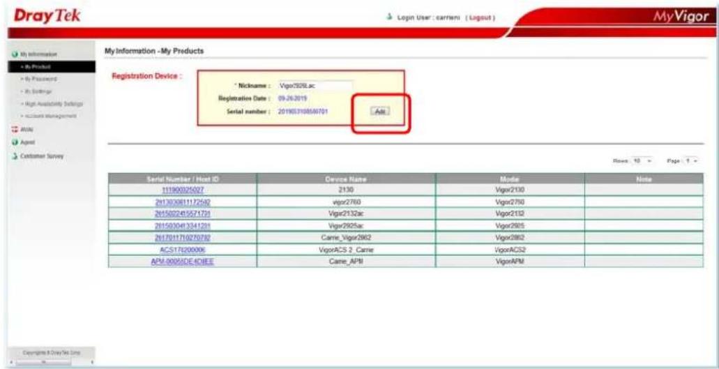
text_image
DrayTek Login User: carrier ( Layout ) MyVigor My Information - My Products Registration Device : * Nickname : Vigor2508.xc Registration Date : 09-26-2019 Serial number : 201903198589701 Acc Customer Survey Serial Number / Host ID Device Name Mode Note 111900325027 2130 Vigor2130 2x13020811172542 Vigor2760 Vigor2750 2x15022415571721 Vigor2132ac Vigor2132 2x15030413341201 Vigor2905ac Vigor2905 2x17011710270702 Came_Vigor2962 Vigor2862 ACS176200006 VigorACS 2_Carrie VigorACS2 APM-00055DE4DIEE Came_APM VigorAFM Copyright © DrayTek Line- When the following page appears, your router information has been added to the database.

text_image
Login User : carrieni ( Logout )Your device has been successfully added to the database.
OK
- After clicking OK, you will see the following page.
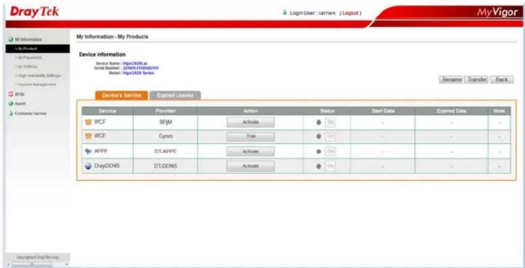
text_image
DrayTek Login User: carrier ( Logout ) MyVigor My Information - My Products Device information Device Name: Vipcr2926 at Serial Number: 2019053100488701 Model: Vipcr2926 Series Fenlame Transfer Back Device's Service Expired License Service Provider Action Status Start Date Expired Date Note WICF BPM Active On - - - WICF Cyron True On - - - APPE DT.APPE Active On - - - DrayODNS DT.ODNS Active On - - -- There are several services provided for this device. Choose one of the services and click Activate or Trial to use the selected service.
| Service | Provider | Action | Status | |
| WCF | BPjM | Activate | On | |
| WCF | Cyren | Trial | On | |
| APPE | DT-APPE | Activate | On | |
| DrayDDNS | DT-DDNS | Activate | On |
- In this case, we choose the WCF service offered by Cyren. Click Trial to get the following page. Check the box of "I have read and accept the ....." and click Next.
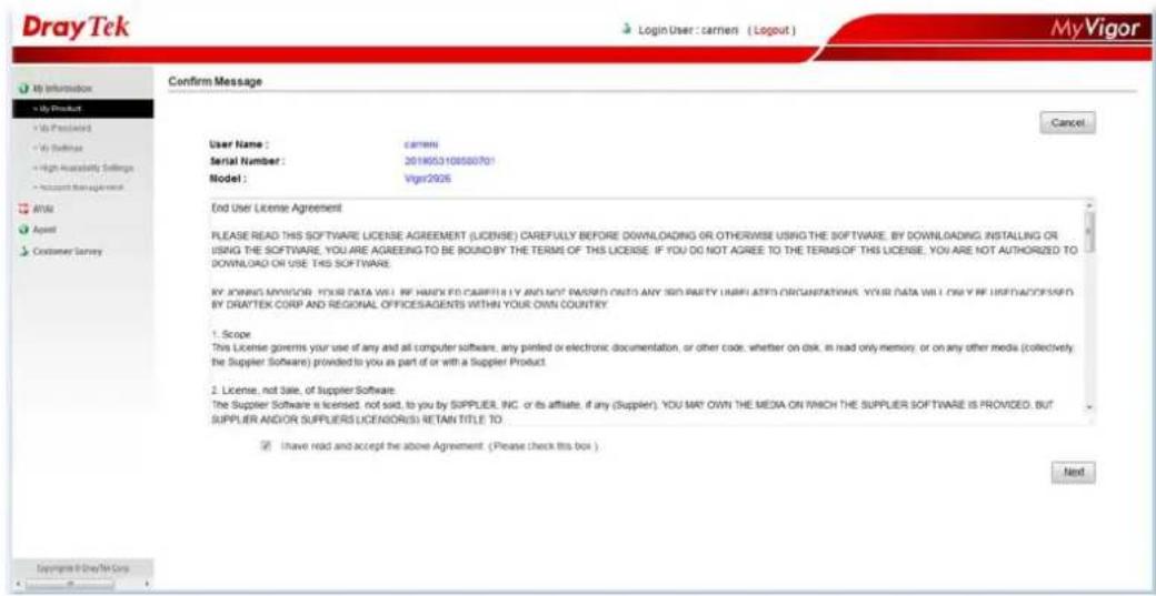
text_image
DrayTek Login User : carriers ( Logout ) MyVigor My Information + My Product + Us Product + Us Software + High Inability Settings + Account Management AffM Agent Customer Survey Confirm Message User Name : carrier Serial Number : 201905.0108500701 Model : Vigr2026 End User License Agreement PLEASE READ THIS SOFTWARE LICENSE AGREEMENT (LICENSE) CAREFULLY BEFORE DOWNLOADING OR OTHERWISE USING THE SOFTWARE, BY DOWNLOADING INSTALLING OR USING THE SOFTWARE, YOU ARE AGREEING TO BE BOUND BY THE TERMS OF THIS LICENSE. IF YOU DO NOT AGREE TO THE TERMS OF THIS LICENSE, YOU ARE NOT AUTHORIZED TO DOWNLOAD OR USE THIS SOFTWARE. BY ORDER MYVIGOR YOUR DATA WILL BE HANDLED CABBRELLY AND NOT PASSED ONTO ANY SSD PARTY UNIFIED ORGANIZATION. YOUR DATA WILL ONLY BE INSTALLED. BY DRAFTEK CORP AND REGIONAL OFFICESAGENTS WITHIN YOUR OWN COUNTRY. 1. Scope This License governs your use of any and all computer software, any printed or electronic documentation, or other code, whether on disk, in read only memory, or on any other media (collectively, the Supplier Software) provided to you as part of or with a Supplier Product. 2. License, not Sale, of Supplier Software. The Supplier Software is licensed, not sold, to you by SUPPLIER, INC. or its affiliate, if any (Supplier). YOU MAY OWN THE MEDIA ON WHICH THE SUPPLIER SOFTWARE IS PROVIDED. BUT SUPPLIER AND/OR SUPPLIERS LICENSIORS RETAIN TITLE TO ✓ Have held and accept the above Agreement. (Please check this box ) Next Copyright © DrayTek Corp Copyright © DrayTek Corp- When the following page appears, click Register.
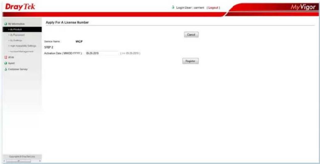
text_image
DrayTek Login User : carrier ( Logout ) MyVigor Apply For A License Number Cancel Service Name: WCF STEP 2 Activation Date ( MMDD-YYYY ) 05-26-2019 ( => 19-26-2019 ) Register Copyright & DrayTek Corp.- Later, the following page will appear with the valid time for the activated service.
DrayTek Service Activation
| Service Name | Start Date | Expire Date | Status |
| Web Content filter | 2019-09-26 | 2019-10-26 | Cyren |
| APP Enforcement | --- | --- | Not Activated |
| DDNS | --- | --- | Not Activated |
Please check if the license fits with the service provider of your signature. To ensure normal operation for your router, update your signature again is recommended.
Copyright © DrayTek Corp. All Rights Reserved.
I-8-2 Service Status
This page displays information related to MyVigor service(s) for this device.
If the router has been registered to MyVigor server successfully,
- "Login to MyVigor" page will appear after clicking MyVigor Services >> Service Status.
text_image
Login to MyVigor comeni ********************************************************************** ✓ I agree this function to record MyVigor account and email address on the device. LoginEnter the account and the password. Check the box of "I agree...." and click Login.
Service Status | Refresh | Renew License | Clear account's info |
Device Information
Model Name: Vigor2926Lac
Serial Number: 2019053108580701
MAC Address: 00-1D-AA-73-4A-78
Owner Account: carrieni [Transfer this device to another account]
Email: ca*****i@draytek.com
Note: The above information will NOT be transferred to other device when restoring configuration file, and will be cleared after resetting.
Device Service
| Service | Provider | Start Date | End Date |
| Web Content Filter | Cyren | 2019-09-26 | 2019-10-26 |
| APP Enforcement | Not Activated | - | - |
| DrayDDNS | Not Activated | - | - |
If the router has NOT been registered to MyVigor server, the following status page will appears instead,
Service Status
Device Information
Model Name: Vigor2926Lac
Serial Number: 2019053108580701
MAC Address: 00-1D-AA-73-4A-78
Owner Account: Not Registered, Please register the router first!!!
Device Service
| Service | Provider | Start Date | End Date |
| Web Content Filter | Not Activated | - | - |
| APP Enforcement | Not Activated | - | - |
| DrayDDNS | Not Activated | - | - |
This page is left blank.
Part II Connectivity
WAN

LAN

NAT

Applications

Routing
It means wide area network. Public IP will be used in WAN.
It means local area network. Private IP will be used in LAN. Local Area Network (LAN) is a group of subnets regulated and ruled by router. The design of network structure is related to what type of public IP addresses coming from your ISP.
When the data flow passing through, the Network Address Translation (NAT) function of the router will dedicate to translate public/private addresses, and the packets will be delivered to the correct host PC in the local area network.
DDNS, LAN DNS, IGMP, LDAP, UPnP, WOL, RADIUS, SMS, Bonjour, HA, Local 802.1X
Static Route, Load-Balance/ Route Policy, BGP
It allows users to access Internet.
Basics of Internet Protocol (IP) Network
IP means Internet Protocol. Every device in an IP-based Network including routers, print server, and host PCs, needs an IP address to identify its location on the network. To avoid address conflicts, IP addresses are publicly registered with the Network Information Centre (NIC). Having a unique IP address is mandatory for those devices participated in the public network but not in the private TCP/IP local area networks (LANs), such as host PCs under the management of a router since they do not need to be accessed by the public. Hence, the NIC has reserved certain addresses that will never be registered publicly. These are known as private IP addresses, and are listed in the following ranges:
From 10.0.0.0 to 10.255.255.255
From 172.16.0.0 to 172.31.255.255
From 192.168.0.0 to 192.168.255.255
What are Public IP Address and Private P Address
As the router plays a role to manage and further protect its LAN, it interconnects groups of host PCs. Each of them has a private IP address assigned by the built-in DHCP server of the Vigor router. The router itself will also use the default private IP address: 192.168.1.1 to communicate with the local hosts. Meanwhile, Vigor router will communicate with other network devices through a public IP address. When the data flow passing through, the Network Address Translation (NAT) function of the router will dedicate to translate public/private addresses, and the packets will be delivered to the correct host PC in the local area network. Thus, all the host PCs can share a common Internet connection.
Get Your Public IP Address from ISP
In ADSL deployment, the PPP (Point to Point)-style authentication and authorization is required for bridging customer premises equipment (CPE). Point to Point Protocol over Ethernet (PPPoE) connects a network of hosts via an access device to a remote access concentrator or aggregation concentrator. This implementation provides users with significant ease of use. Meanwhile it provides access control, billing, and type of service according to user requirement.
When a router begins to connect to your ISP, a serial of discovery process will occur to ask for a connection. Then a session will be created. Your user ID and password is authenticated via PAP or CHAP with RADIUS authentication system. And your IP address, DNS server, and other related information will usually be assigned by your ISP.
Network Connection by 3G/4G USB Modem
For 3G/4G mobile communication through Access Point is popular more and more, Vigor2926 adds the function of 3G/4G network connection for such purpose. By connecting 3G USB Modem to the USB port of Vigor2926, it can support HSDPA/UMTS/EDGE/GPRS/GSM and the future 3G/4G standard (HSUPA, etc). Vigor2926n with 3G/4G USB Modem allows you to receive 3G signals at any place such as your car or certain location holding outdoor activity and share the bandwidth for using by more people. Users can use four LAN ports on the router to access Internet. Also, they can access Internet via 802.11n wireless function of Vigor2926n, and enjoy the powerful firewall, bandwidth management, VPN features of Vigor2926n series.
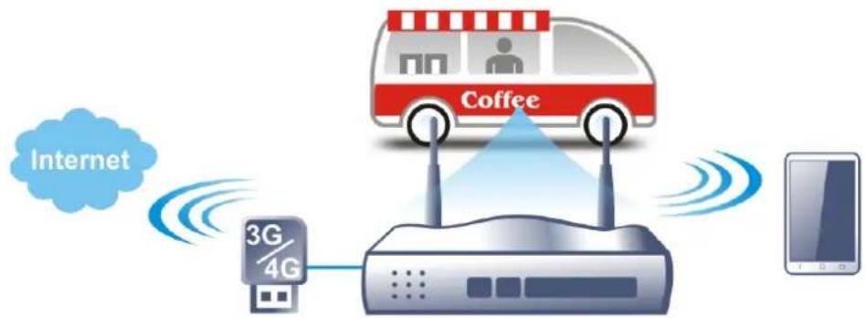
flowchart
graph TD
    A["Coffee Truck"] -->|Wireless Signal| B["3G/4G Router"]
    B --> C["Internet"]
    C -->|Wireless Signal| A
After connecting into the router, 3G/4G USB Modem will be regarded as the third WAN port. However, the original WAN1 and WAN2 still can be used and Load-Balance can be done in the router. Besides, 3G/4G USB Modem in WAN3 also can be used as backup device. Therefore, when WAN1 and WAN2 are not available, the router will use 3.5G for supporting automatically. The supported 3G/4G USB Modem will be listed on DrayTek web site. Please visit www.draytek.com for more detailed information.
LTE Application
Service Network

flowchart
graph TD
    A["Applied Models: Mobile Banking/Logistic/Manufacturing /Real Estate/Healthcare"] --> B["• e-Order"]
    A --> C["• Tracking of logistic status"]
    A --> D["• Project development status"]
    A --> E["• ERP"]
    A --> F["• Con-call"]
    A --> G["• e-Healthcare (e.g. medical record)"]
    H["Mobile Office"] --> I["Backup of Different Network Infrastructure"]
    I --> J["3G/4G Router Backup"]
    J --> K["4G/LTE Mobile Operators"]
    K --> L["Encrypted tunnel via IP-VPN"]
    L --> M["Corp. Intranet"]
    M --> N["Remote Management Portal"]
    N --> O["Smart Meter for Utility"]
    N --> P["Smart Meter for Water"]
    N --> Q["Surveillance"]
Web User Interface
WAN
General Setup
Internet Access
Multi-VLAN
WAN Budget
II-1-1 General Setup
This section will introduce some general settings of Internet and explain the connection modes for WAN1, WAN2, WAN3 (or LTE) and WAN4 in details.
This router supports multiple-WAN function. It allows users to access Internet and combine the bandwidth of the multiple WANs to speed up the transmission through the network. Each WAN port can connect to different ISPs, Even if the ISPs use different technology to provide telecommunication service (such as DSL, Cable modem, etc.). If any connection problem occurred on one of the ISP connections, all the traffic will be guided and switched to the normal communication port for proper operation. Please configure WAN1, WAN2, WAN3 (or LTE) and WAN4 settings.
This webpage allows you to set general setup for WAN1, WAN2, WAN3 (or LTE) and WAN4 respectively.
For all of the routers except for Vigor2926L series ---
WAN >> General Setup
Load Balance Mode: Auto Weight IP Based Advance
| Index | Enable | Physical Mode/Type | Line Speed(Kbps) DownLink/UpLink | Active Mode | Load Balance |
| WAN1 | √ | Ethernet/Auto negotiation | 0 / 0 | Always On | V |
| WAN2 | √ | Ethernet/Auto negotiation | 0 / 0 | Always On | V |
| WAN3 | √ | USB/- | 0 / 0 | Always On | V |
| WAN4 | √ | USB/- | 0 / 0 | Always On | V |
Note:
The line speed setting of WAN interface is available only when According to Line Speed is selected as the Load Balance Mode.
OK Cancel
For Vigor2926L series ----
Load Balance Mode: Auto Weight IP Based Advance
| Index | Enable | Physical Mode/Type | Line Speed(Kbps) DownLink/UpLink | Active Mode | Load Balance |
| WAN1 | √ | Ethernet/Auto negotiation | 0 / 0 | Always On | V |
| WAN2 | √ | Ethernet/Auto negotiation | 0 / 0 | Always On | V |
| LTE | √ | USB/- | 0 / 0 | Always On | V |
| WAN4 | √ | USB/- | 0 / 0 | Always On | V |
Note:
The line speed setting of WAN interface is available only when According to Line Speed is selected as the Load Balance Mode.

Available settings are explained as follows:
| Item | Description |
Load Balance Mode This option is available for multiple-WAN for getting enough bandwidth for each WAN port. If you know the practical bandwidth for your WAN interface, please choose the setting of According to Line Speed. Otherwise, please choose Auto Weight to let the router reach the best load balance.IP Based - The same source / destination IP pair will select the same WAN interface as policy. It is the default setting.Sesseion Based- All of the WAN interfaces will be used (as out-going WAN) for passing through new sessions to get better transmission speed. Though good speed test result for throughput might be reached; however, some web site may not open smoothly, especially the site need authentication, e.g., FTP.Advance - Load Balance for the traffic of STUN, google STUN, and SIP are disabled in default to prevent from conflict. The following dialog allows you to define protocol, port and name for the traffic not to be applied with load balance. That is, when an item is enabled (checked), it might not be affected by load balance.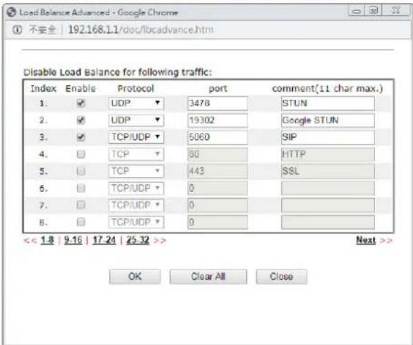 If you have no strong demand about speed test result, keep default settings as IP based. If you have no strong demand about speed test result, keep default settings as IP based. | |
| Index | Click the WAN interface link under Index to access into the WAN configuration page. |
| Enable | V means such WAN interface is enabled and ready to be used. |
| Physical Mode / Type Display | the physical mode and physical type of such WAN interface. |
| Line Speed(Kbps)DownLink/UpLink | Display the downstream and upstream rate of such WAN interface. |
| Active Mode Display whether | such WAN interface is Active device or backup device. |
| Load Balance V means the function of load balance for such WAN interface is enabled. | |

Info
In default, each WAN port is enabled.
After finished the above settings, click OK to save the settings.
II-1-1-1 WAN1/WAN2 with Ethernet
WAN1/ WAN2 is fixed with physical mode of Ethernet.
WAN >> General Setup
WAN 1
| Enable: | Yes ▼ | |||
| Display Name: | ||||
| Physical Mode: | Ethernet | |||
| Physical Type: | Auto negotiation ▼ | |||
| Line Speed(Kbps): | ||||
| DownLink | 0 | |||
| UpLink | 0 | |||
| Active Mode: | Failover ▼ Load Balance: ✓ | |||
| WAN Failure | ||||
| Traffic Threshold | ||||
| Upload User defined OK bps (Default unit: K) | ||||
| Download User defined OK bps (Default unit: K) | ||||
| Active When: | Any of the selected WAN disconnect | |||
| All of the selected WAN disconnect | ||||
| WAN 1 WAN 2 WAN 3 WAN 4 | ||||
| VLAN Tag Insertion | Customer (TPID 0x8100) | Service (TPID 0x8100) | ||
| Disable ▼ | Disable ▼ | |||
| Tag value Priority | Tag value Priority | |||
| 0 0 | 0 0 | |||
| (0~4095) (0~7) | (0~4095) (0~7) | |||
Note:
-
The line speed setting of WAN interface is available only when According to Line Speed is selected as the Load Balance Mode.
-
Customer and service tag are used for different network environments. Customer tag is required for most ISPs while Service tag is required when ISP needs QinQ packets.

Available settings are explained as follows:
| Item | Description |
| Enable | Choose Yes to invoke the settings for this WAN interface.Choose No to disable the settings for this WAN interface. |
| Display Name Enter the description for such WAN interface. | |
| Physical Mode Display the physical mode of such WAN interface. | |
| Physical Type | You can change the physical type for WAN2 or choose Auto negotiation for determined by the system.[IMAGE] |
| Line Speed | If your choose According to Line Speed as the Load Balance Mode, please type the line speed for downloading and uploading for such WAN interface. The unit is kbps. |
| Active Mode | Choose Always On to make the WAN connection beactivated always.Load Balance: Check this box to enable auto load balance function for such WAN interface.When the data traffic is large, the WAN interface with the function enabled will balance the data transmission automatically among all of the WAN interfaces in connection status.Failover - Choose it to make the WAN connection as a backup connection.WAN Failure - When the active WAN failed, such WAN will be activated as the main network connection.Traffic Threshold - When the data traffic of active WAN reaches the traffic threshold (specified here), the failover WAN will be enabled automatically to share the overloaded data traffic. |
| Active When | If you choose Failover as the Active Mode, Active When will appear. Please specify which WAN will be the Backup interface.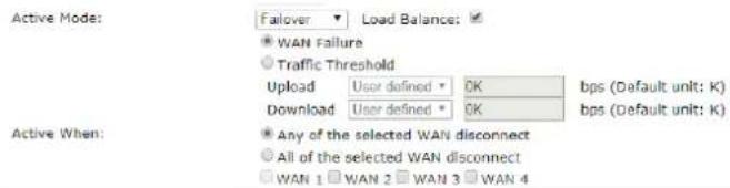 Any of the selected WAN disconnect - Such backup WAN will be activated when any master WAN interface disconnects.All of the selected WAN disconnect - Such backup WAN will be activated only when all master WAN interfaces disconnect. Any of the selected WAN disconnect - Such backup WAN will be activated when any master WAN interface disconnects.All of the selected WAN disconnect - Such backup WAN will be activated only when all master WAN interfaces disconnect. |
| VLAN Tag insertion Such feature is offered to the user with the environment supporting IEEE_802.1ad. In which, service is used for outer tag; customer is used for inner tag.Enable - Enable the function of VLAN with tag.The router will add specific VLAN number to all packets on the WAN while sending them out.Please type the tag value and specify the priority for the packets sending by WAN interface.Disable - Disable the function of VLAN with tag.Tag value - Enter the value as the VLAN ID number. The range is from 0 to 4095.Priority - Enter the packet priority number for such VLAN. The range is from 0 to 7. | |
After finished the above settings, click OK to save the settings.
II-1-1-2 WAN3/WAN4 (USB)
To use 3G/4G network connection through 3G/4G USB Modem, please configure WAN3 or WAN4 interface.
WAN >> General Setup
WAN 3
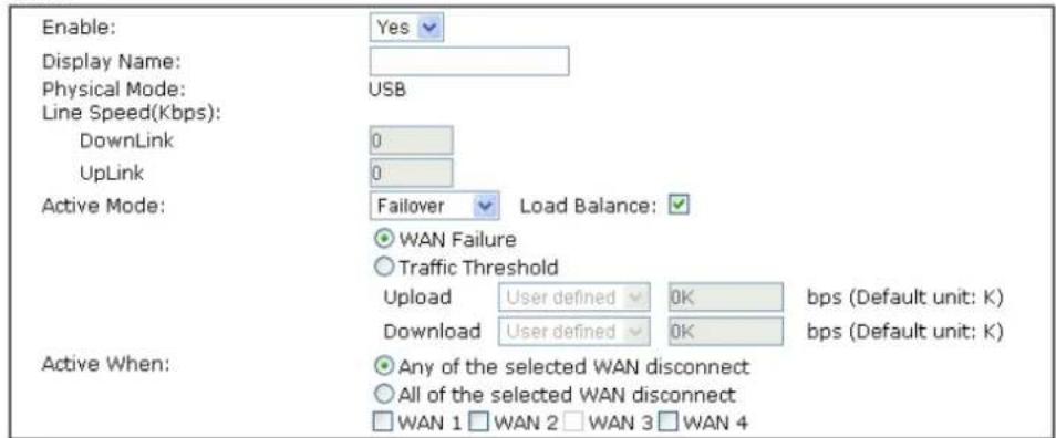
text_image
Enable: Display Name: Physical Mode: Line Speed(Kbps): DownLink UpLink Active Mode: Load Balance: WAN Failure Traffic Threshold Upload User defined 0K bps (Default unit: K) Download User defined 0K bps (Default unit: K) Active When: Any of the selected WAN disconnect All of the selected WAN disconnect WAN 1 WAN 2 WAN 3 WAN 4Note:
The line speed setting of WAN interface is available only when According to Line Speed is selected as the Load Balance Mode.

Or (LTE model)
WAN >> General Setup
WAN 3
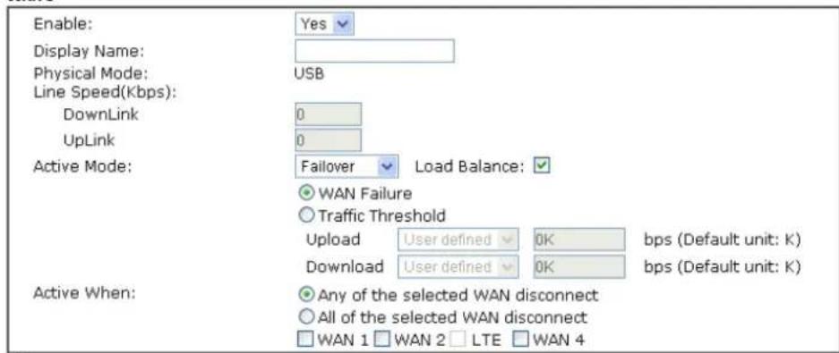
text_image
Enable: Display Name: Physical Mode: Line Speed(Kbps): DownLink UpLink Active Mode: Failover Load Balance: WAN Failure Traffic Threshold Upload User defined 0K bps (Default unit: K) Download User defined 0K bps (Default unit: K) Active When: Any of the selected WAN disconnect All of the selected WAN disconnect WAN 1 WAN 2 LTE WAN 4Note:
The line speed setting of WAN interface is available only when According to Line Speed is selected as the Load Balance Mode.

Available settings are explained as follows:
| Item | Description |
| Enable | Choose Yes to invoke the settings for this WAN interface.Choose No to disable the settings for this WAN interface. |
| Display Name Enter the description for such WAN interface. | |
| Physical Mode Display the physical mode of such WAN interface. | |
| Line Speed | If your choose According to Line Speed as the Load Balance Mode, please type the line speed for downloading and uploading for such WAN interface. The unit is kbps. |
| Active Mode | Choose Always On to make the WAN2 connection being activated always. Load Balance: Check this box to enable auto load balance function for such WAN interface.When the data traffic is large, the WAN interface with the function enabled will balance the data transmission automatically among all of the WAN interfaces in connection status.Failover - Choose it to make the WAN connection as a backup connection.WAN Failure - When the active WAN failed, such WAN will be activated as the main network connection.Traffic Threshold - When the data traffic of active WAN reaches the traffic threshold (specified here), the failover WAN will be enabled automatically to share the overloaded data traffic. Load Balance: Check this box to enable auto load balance function for such WAN interface.When the data traffic is large, the WAN interface with the function enabled will balance the data transmission automatically among all of the WAN interfaces in connection status.Failover - Choose it to make the WAN connection as a backup connection.WAN Failure - When the active WAN failed, such WAN will be activated as the main network connection.Traffic Threshold - When the data traffic of active WAN reaches the traffic threshold (specified here), the failover WAN will be enabled automatically to share the overloaded data traffic. |
| Active When | If you choose Failover as the Active Mode, Active When will appear. Please specify which WAN will be the Backup interface.Active Mode: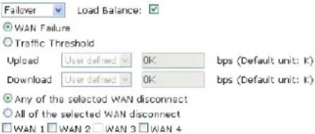 Active When:Any of the selected WAN disconnect - Such backup WAN will be activated when any master WAN interface disconnects.All of the selected WAN disconnect - Such backup WAN will be activated only when all master WAN interfaces disconnect. Active When:Any of the selected WAN disconnect - Such backup WAN will be activated when any master WAN interface disconnects.All of the selected WAN disconnect - Such backup WAN will be activated only when all master WAN interfaces disconnect. |
After finished the above settings, click OK to save the settings.
II-1-2 Internet Access
For the router supports multi-WAN function, the users can set different WAN settings (for WAN1/WAN2/WAN3 or LTE/WAN4) for Internet Access. Due to different Physical Mode for WAN interface, the Access Mode for these connections also varies. Refer to the following figures for examples.
Access Mode for Etherenet,
WAN >> Internet Access
Internet Access
| Index | Display Name | Physical Mode | Access Mode | |
| WAN1 | Ethernet | Static or Dynamic IP | Details Page IPv6 | |
| WAN2 | Ethernet | None PPPoE | Details Page IPv6 | |
| WAN3 | USB | Static or Dynamic IP PPTP/L2TP | Details Page IPv6 | |
| WAN4 | USB | None | Details Page IPv6 | |
Note:
- Device on USB port 1 applies WAN3 configuration.
2.Device on USB port 2 applies WAN4 configuration.
DHCP Client Option
Access Mode for USB,
WAN >> Internet Access
Internet Access
| Index | Display Name | Physical Mode | Access Mode | ||
| WAN1 | Ethernet | Static or Dynamic IP | Details Page | IPv6 | |
| WAN2 | Ethernet | Static or Dynamic IP | Details Page | IPv6 | |
| WAN3 | USB | None | Details Page | IPv6 | |
| WAN4 | USB | None3G/4G USB Modem(PPP mode)3G/4G USB Modem(DHCP mode) | Details Page | IPv6 | |
- Device on USB port 1 applies WAN3 configuration.
2.Device on USB port 2 applies WAN4 configuration.
DHCP Client Option
Access Mode for LTE (for L model only),
Internet Access
| Index | Display Name | Physical Mode | Access Mode | ||
| WAN1 | Ethernet | Static or Dynamic IP | Details Page | IPv6 | |
| WAN2 | Ethernet | Static or Dynamic IP | Details Page | IPv6 | |
| LTE | USB | 3G/4G LTE Modem(DHCP mode) | Details Page | IPv6 | |
| WAN4 | USB | None | Details Page | IPv6 |
Note:
Device on USB port applies WAN4 configuration.
DHCP Client Option
Available settings are explained as follows:
| Item | Description |
| Index Display the WAN interface. | |
| Display Name It shows the name of the WAN1/ WAN2/ WAN3 or LTE/ WAN4 that entered in general setup. | |
| Physical Mode It shows the physical connection for WAN1/ WAN2 (Ethernet) / WAN3 or LTE / WAN4 (USB) according to the real network connection. | |
| Access Mode Use the drop down list to choose a proper access mode. The details page of that mode will be popped up. If not, click Details Page for accessing the page to configure the settings. | |
| Details Page This button will open different web page (based on IPv4) according to the access mode that you choose in WAN interface. | |
| IPv6 This button will open different web page (based on Physical Mode) to setup IPv6 Internet Access Mode for WAN interface. If IPv6 service is active on this WAN interface, the color of “IPv6” will become green. | |
| DHCP Client Option | This button allows you to configure DHCP client options. DHCP packets can be processed by adding option number and data information when such function is enabled and configured. |
WAN >> Internet Access
DHCP Client Options Status
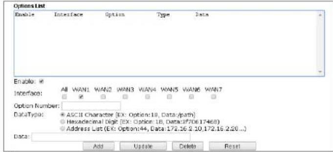
text_image
Options List Enable Interface Option Type Data Enable: Interface: All WAN1 WAN2 WAN3 WAN4 WAN5 WAN6 WAN7 Option Number: DataType: ASCII Character (EX: Option:18, Data:/path) Hexadecimal Digit (EX: Option: 18, Data:2f70617468) Address List (EX: Option:44, Data:172.16 2.10,172.16 2.20...) Data: Add Update Delete ResetNote:
1. Option 12 is reserved. You cannot configure it here, but you can configure it in "Router Name" field of "WAN >> Internet Access >> Details Page".
2. Option 55 is reserved and configured with value 1, 3, 6, 15 and 212, also 33 and 121 for some models.
3. Configuring option 61 here will override the setting in "WAN >> Internet Access" page's DHCP Client Identifier field.

Enable/Disable - Enable/Disable the function of DHCP Option. Each DHCP option is composed by an option number with data. For example,
Option number:100
Data: abcd
When such function is enabled, the specified values for DHCP option will be seen in DHCP reply packets.
Interface - Specify the WAN interface(s) that will be overwritten by such function. WAN5 \~ WAN7 can be located under WAN>>Multi-PVC/VLAN.
Option Number - Type a number for such function.
Note: If you choose to configure option 61 here, the detailed settings in WAN>>Interface Access will be overwritten.
DataType - Choose the type (ASCII or Hex) for the data to be stored.
Data - Enter the content of the data to be processed by the function of DHCP option.
II-1-2-1 Details Page for PPPoE in WAN1/WAN2 (Physical Mode: Ethernet)
To use PPPoE as the accessing protocol of the internet, please click the PPPoE tab. The following web page will be shown.
WAN >> Internet Access
WAN 1
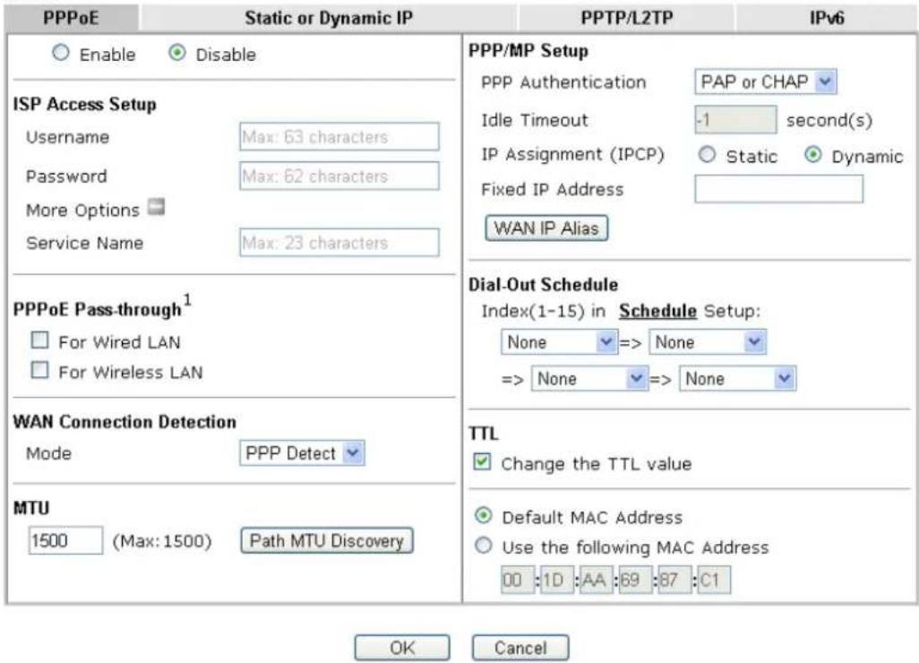
text_image
PPPoE Static or Dynamic IP PPTP/L2TP IPv6 Enable Disable ISP Access Setup Username Max: 63 characters Password Max: 62 characters More Options Service Name Max: 23 characters PPPoE Pass-through¹ For Wired LAN For Wireless LAN WAN Connection Detection Mode PPP Detect MTU 1500 (Max: 1500) Path MTU Discovery PPP/MP Setup PPP Authentication PAP or CHAP Idle Timeout -1 second(s) IP Assignment (IPCP) Static Dynamic Fixed IP Address WAN IP Alias Dial-Out Schedule Index(1-15) in Schedule Setup: None => None => None => None TTL Change the TTL value Default MAC Address Use the following MAC Address 00 :1D :AA :69 :87 :C1 OK CancelAvailable settings are explained as follows:
| Item | Description |
| Enable/Disable | Click Enable for activating this function. If you click Disable, this function will be closed and all the settings that you adjusted in this page will be invalid. |
| ISP Access Setup Enter your | allocated username, password and authentication parameters according to the information provided by your ISP.Usage - Type in the username provided by ISP in this field.The maximum length of the user name you can set is 63 characters.Password - Type in the password provided by ISP in this field.The maximum length of the password you can set is 62 characters.More Options - It shows optional settings for configuration service Name (Optional) - Enter the description of the specific network service. |
| PPPoE Pass-through The router offers PPPoE dial-up connection. Besides, you also can establish the PPPoE connection directly from local clients to your ISP via the Vigor router. When PPPoA protocol is selected, the PPPoE package transmitted by PC will be | |
WAN Connection Detection
transformed into PPPoA package and sent to WAN server. Thus, the PC can access Internet through such direction.
For Wired LAN - If you check this box, PCs on the same network can use another set of PPPoE session (different with the Host PC) to access into Internet.
For Wireless LAN - It is available for n model. If you check this box, PCs on the same wireless network can use another set of PPPoE session (different with the Host PC) to access into Internet.
Note: To have PPPoA Pass-through, please choose PPPoA protocol and check the box(es) here. The router will behave like a modem which only serves the PPPoE client on the LAN. That's, the router will offer PPPoA dial-up connection.
Such function allows you to verify whether network connection is alive or not through PPP Detect or Ping Detect. Mode - Choose PPP Detect or Ping Detect for the system to execute for WAN detection. If you choose Ping Detect as the detection mode, you have to type required settings for the following items.
- Primary/Secondary Ping IP - If you choose Ping Detect as detection mode, you have to type Primary or Secondary IP address in this field for pinging.
- Ping Gateway IP – If you choose Ping Detect as detection mode, you also can enable this setting to use current WAN gateway IP address for pinging. With the IP address(es) pinging, Vigor router can check if the WAN connection is on or off.
- TTL (Time to Live) - Set TTL value of PING operation.
- Ping Interval - Enter the interval for the system to execute the PING operation.
- Ping Retry - Enter the number of times that the system is allowed to execute the PING operation before WAN disconnection is judged.
MTU It means Max Transmit Unit for packet.
Path MTU Discovery - It is used to detect the maximum MTU size of a packet not to be segmented in specific transmit path.
Click Detect to open the following dialog.
- Path MTU to - Enter the IP address as the specific transmit path.
- MTU reduce size by – It determines the decreasing size of MTU value. For example, the number specified in this field is “8”. The maximum MTU size is “1500”. After clicking the “detect” button, the system will calculate and get the suitable MTU value such as 1500, 1492, 1484 and etc., automatically.
| Detect - Click it to detect a suitable MTU valueAccept - After clicking it, the detected value will be displayed in the field of MTU. | |
| PPP/MP Setup | PPP Authentication - Select PAP only or PAP or CHAP for PPP.Idle Timeout - Set the timeout for breaking down the Internet after passing through the time without any action.IP Assignment (IPCP) - Usually ISP dynamically assigns IP address to you each time you connect to it and request. In some case, your ISP provides service to always assign you the same IP address whenever you request. In this case, you can fill in this IP address in the Fixed IP field. Please contact your ISP before you want to use this function.Fixed IP Address- Enter a fixed IP address in the box of Fixed IP Address.WAN IP Alias - If you have multiple public IP addresses and would like to utilize them on the WAN interface, please use WAN IP Alias. You can set up to 32 public IP addresses other than the current one you are using. Enter the additional WAN IP address and check the Enable box. Then click OK to exit the dialog. |
| Dial-Out Schedule | Index (1-15) in Schedule Setup - You can type in four sets of time schedule for your request. All the schedules can be set previously in Application >> Schedule web page and you can use the number that you have set in that web page. |
| TTL Change the TTL value | Enable or disable the TTL (Time to Live) for a packet transmitted through Vigor router.If enabled - TTL value will be reduced (-1) when it passes through Vigor router. It will cause the client, accessing Internet through Vigor router, be blocked by certain ISP when TTL value becomes “0”.If disabled - TTL value will not be reduced. Then, when a packet passes through Vigor router, it will not be cancelled. That is, the client who sends out the packet will not be blocked by ISP.Default MAC Address - You can use Default MAC Address or specify another MAC address by typing on the boxes of MAC Address for the router.Specify a MAC Address - Enter the MAC address for the router manually. |
After finishing all the settings here, please click OK to activate them.
II-1-2-2 Details Page for Static or Dynamic IP in WAN1/WAN2 (Physical Mode: Ethernet)
For static IP mode, you usually receive a fixed public IP address or a public subnet, namely multiple public IP addresses from your DSL or Cable ISP service providers. In most cases, a Cable service provider will offer a fixed public IP, while a DSL service provider will offer a public subnet. If you have a public subnet, you could assign an IP address or many IP address to the WAN interface.
To use Static or Dynamic IP as the accessing protocol of the internet, please click the Static or Dynamic IP tab. The following web page will be shown.
WAN >> Internet Access
WAN 1
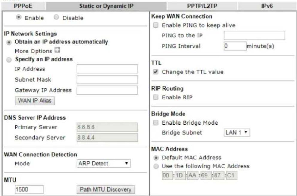
text_image
PPPoE Static or Dynamic IP PPTP/L2TP IPv6 Enable Disable IP Network Settings Obtain an IP address automatically More Options Specify an IP address IP Address Subnet Mask Gateway IP Address WAN IP Alias DNS Server IP Address Primary Server 8.8.8.8 Secondary Server 8.8.4.4 WAN Connection Detection Mode ARP Detect MTU 1500 Path MTU Discovery Keep WAN Connection Enable PING to keep alive PING to the IP PING Interval 0 minute(s) TTL Change the TTL value RIP Routing Enable RIP Bridge Mode Enable Bridge Mode Bridge Subnet LAN 1 ▼ MAC Address Default MAC Address Use the following MAC Address 00 :1D :AA :69 :87 :C1Note:
- VPN feature may be affected when the value of MTU is changed, please also check your value of VPN mss by using "VPN mss set" command. We recommend to put the same decreased value on VPN mss. For example, reducing the MTU from 1500 -> 1400, then it will need to reduct 100 from mss value.
- If enable firewall in bridge mode, IPv6 connection type would be change to DHCPv6 mode.
- Bridge Subnet cannot be selected by Multi-WAN Interface at the same time.
- If both Bridge Mode and Firewall are enabled, the settings under User Management will be ignored.
OK Cancel
Available settings are explained as follows:
| Item | Description |
| Enable / Disable | Click Enable for activating this function. If you click Disable, this function will be closed and all the settings that you adjusted in this page will be invalid. |
| IP Network Settings | This group allows you to obtain an IP address automatically and allows you type in IP address manually.Obtain an IP address automatically - Click this button to obtain the IP address automatically if you want to use Dynamic IP mode.More Options - It shows optional settings for configuration.● Router Name: Type in the router name provided by ISP.● Domain Name: Type in the domain name that you have assigned.● Enable DHCP Client Identifier: Check the box to specify username and password as the DHCP client identifier for some ISP.● Username: Type a name as username. The maximum length of the user name you can set is 63 characters.● Password: Type a password. The maximum length of the password you can set is 62 characters.Specify an IP address - Click this radio button to specify some data if you want to use Static IP mode.● IP Address: Enter the IP address.● Subnet Mask: Enter the subnet mask.● Gateway IP Address: Enter the gateway IP address.WAN IP Alias - If you have multiple public IP addresses and would like to utilize them on the WAN interface, please use WAN IP Alias. You can set up to 32 public IP addresses other than the current one you are using. |
| DNS Server IP Address | Type in the primary IP address for the router if you want to use Static IP mode. If necessary, type in secondary IP address for necessity in the future. |
| WAN Connection Detection | Such function allows you to verify whether network connection is alive or not through ARP Detect or Ping Detect.Mode - Choose ARP Detect, Ping Detect or Always On for the system to execute for WAN detection. If you choose Ping Detect as the detection mode, you have to type required settings for the following items.● Primary/Secondary Ping IP - If you choose Ping Detect as detection mode, you have to type Primary or Secondary IP address in this field for pinging.● Ping Gateway IP - If you choose Ping Detect as detection mode, you also can enable this setting to use current WAN gateway IP address for pinging.With the IP address(es) pinging, Vigor router can check if the WAN connection is on or off.● TTL (Time to Live) - Set TTL value of PING operation.● Ping Interval - Enter the interval for the system to execute the PING operation.● Ping Retry - Enter the number of times that the system is allowed to execute the PING operation before WAN disconnection is judged. |
| MTU It means Max Transmit | Unit for packet.Path MTU Discovery - It is used to detect the maximum MTU size of a packet not to be segmented in specific transmit path.Click Detect to open the following dialog. |
    Note: You may reduce the Path MTU Size(max 1500) by 1 to 100.Accept CancelPath MTU to - Enter the IP address as the specific transmit path.MTU reduce size by - It determines the decreasing size of MTU value. For example, the number specified in this field is “8”. The maximum MTU size is “1500”. After clicking the “detect” button, the system will calculate and get the suitable MTU value such as 1500, 1492, 1484 and etc., automatically.Detect - Click it to detect a suitable MTU valueAccept - After clicking it, the detected value will be displayed in the field of MTU. Note: You may reduce the Path MTU Size(max 1500) by 1 to 100.Accept CancelPath MTU to - Enter the IP address as the specific transmit path.MTU reduce size by - It determines the decreasing size of MTU value. For example, the number specified in this field is “8”. The maximum MTU size is “1500”. After clicking the “detect” button, the system will calculate and get the suitable MTU value such as 1500, 1492, 1484 and etc., automatically.Detect - Click it to detect a suitable MTU valueAccept - After clicking it, the detected value will be displayed in the field of MTU. | |
| Keep WAN Connection | Normally, this function is designed for Dynamic IP environments because some ISPs will drop connections if there is no traffic within certain periods of time. Check Enable PING to keep alive box to activate this function.PING to the IP - If you enable the PING function, please specify the IP address for the system to PING it for keeping alive.PING Interval - Enter the interval for the system to execute the PING operation. |
| TTL Change the TTL value | Enable or disable the TTL (Time to Live) for a packet transmitted through Vigor router.If enabled - TTL value will be reduced (-1) when it passes through Vigor router. It will cause the client, accessing Internet through Vigor router, be blocked by certain ISP when TTL value becomes “0”.If disabled - TTL value will not be reduced. Then, when a packet passes through Vigor router, it will not be cancelled. That is, the client who sends out the packet will not be blocked by ISP. |
| RIP Protocol | Routing Information Protocol is abbreviated as RIP (RFC1058) specifying how routers exchange routing tables information.Click Enable RIP for activating this function. |
| Bridge Mode Enable Bridge | Mode - If the function is enabled, the router will work as a bridge modem.Enable Firewall - It is available when Bridge Mode is enabled. When both Bridge Mode and Firewall check boxes are enabled, the settings configured (user profiles) under User Management will be ignored. And all of the filter rules defined and enabled in Firewall menu will be activated.Bridge Subnet - Make a bridge between the selected LAN subnet and such WAN interface. |
| MAC Address Default MAC Address: Click this radio button to use default MAC address for the router. | |
| Specify a MAC Address: Some Cable service providers specify a specific MAC address for access authentication. In such cases you need to click the Specify a MAC Address and enter the MAC address in the MAC Address field. | |
After finishing all the settings here, please click OK to activate them.
II-1-2-3 Details Page for PPTP/L2TP in WAN1/WAN2 (Physical Mode: Ethernet)
To use PPTP/L2TP as the accessing protocol of the internet, please click the PPTP/L2TP tab. The following web page will be shown.
WAN >> Internet Access
WAN 1
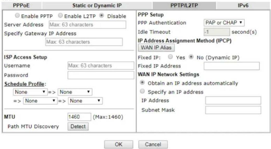
text_image
PPPoE Static or Dynamic IP PPTP/L2TP IPv6 Enable PPTP Enable L2TP Disable Server Address Max: 63 characters Specify Gateway IP Address Max: 63 characters ISP Access Setup Username Max: 63 characters Password Schedule Profile: None => None => None None => None MTU 1460 (Max:1460) Path MTU Discovery Detect PPP Setup PPP Authentication PAP or CHAP ▼ Idle Timeout -1 second(s) IP Address Assignment Method (IPCP) WAN IP Alias Fixed IP: Yes ▼ No (Dynamic IP) Fixed IP Address WAN IP Network Settings Obtain an IP address automatically Specify an IP address IP Address Subnet Mask OK CancelNote:
VPN feature may be affected when the value of MTU is changed, please also check your value of VPN mss by using "VPN mss set" command.
We recommend to put the same decreased value on VPN mss. For example, reducing the MTU from 1500 -> 1400, then it will need to reduct 100 from mss value.
Available settings are explained as follows:
| Item | Description |
| PPTP/L2TP | Enable PPTP- Click this radio button to enable a PPTP client to establish a tunnel to a DSL modem on the WAN interface. Enable L2TP - Click this radio button to enable a L2TP client to establish a tunnel to a DSL modem on the WAN interface. Disable - Click this radio button to close the connection through PPTP or L2TP.Server Address - Specify the IP address of the PPTP/ L2TP server if you enable PPTP/ L2TP client mode.Specify Gateway IP Address - Specify the gateway IP address for DHCP server. |
| ISP Access Setup Username | -Type in the username provided by ISP in this field. The maximum length of the user name you can set is 63 characters.Password -Type in the password provided by ISP in this field. The maximum length of the password you can set is 62characters. Schedule Profile - You can type in four sets of time schedule for your request. All the schedules can be set previously in Application >> Schedule web page and you can use the number that you have set in that web page. |
| Schedule Profile Set the wireless LAN to work at certain time interval only.You may choose up to 4 schedules out of the 15 schedules pre-defined in Applications >> Schedule setup. The default setting of this field is blank and the function will always work. | |
MTU It means Max Transmit Unit for packet.Path MTU Discovery - It is used to detect the maximum MTU size of a packet not to be segmented in specific transmit path.Click Detect to open the following dialog.       Path MTU to - Enter the IP address as the specific transmit path.MTU reduce size by- It determines the decreasing size of MTU value. For example, the number specified in this field is “8”. The maximum MTU size is “1500”. After clicking the “detect” button, the system will calculate and get the suitable MTU value such as 1500, 1492, 1484 and etc., automatically.Detect - Click it to detect a suitable MTU valueAccept - After clicking it, the detected value will be displayed in the field of MTU. Path MTU to - Enter the IP address as the specific transmit path.MTU reduce size by- It determines the decreasing size of MTU value. For example, the number specified in this field is “8”. The maximum MTU size is “1500”. After clicking the “detect” button, the system will calculate and get the suitable MTU value such as 1500, 1492, 1484 and etc., automatically.Detect - Click it to detect a suitable MTU valueAccept - After clicking it, the detected value will be displayed in the field of MTU. | |
| PPP Setup | PPP Authentication - Select PAP only or PAP or CHAP for PPP.Idle Timeout - Set the timeout for breaking down the Internet after passing through the time without any action. |
| IP Address Assignment Method(IPCP) | WAN IP Alias - If you have multiple public IP addresses and would like to utilize them on the WAN interface, please use WAN IP Alias. You can set up to 32 public IP addresses other than the current one you are using.Fixed IP - Usually ISP dynamically assigns IP address to you each time you connect to it and request. In some case, your ISP provides service to always assign you the same IP address whenever you request. In this case, you can fill in this IP address in the Fixed IP field. Please contact your ISP before you want to use this function. Click Yes to use this function and type in a fixed IP address in the box.Fixed IP Address -Type a fixed IP address. |
| WAN IP Network Settings | Obtain an IP address automatically - Click this button to obtain the IP address automatically. |
- Path MTU to - Enter the IP address as the specific transmit path.
- MTU reduce size by- It determines the decreasing size of MTU value. For example, the number specified in this field is "8". The maximum MTU size is "1500". After clicking the "detect" button, the system will calculate and get the suitable MTU value such as 1500, 1492, 1484 and etc., automatically.
- Detect - Click it to detect a suitable MTU value
- Accept – After clicking it, the detected value will be displayed in the field of MTU.
| Specify an IP address - Click this radio button to specify some data.● IP Address - Enter the IP address.● Subnet Mask - Enter the subnet mask. |
After finishing all the settings here, please click OK to activate them.
II-1-2-4 Details Page for 3G/4G USB Modem (PPP mode) in WAN3/WAN4
To use 3G/4G USB Modem (PPP mode) as the accessing protocol of the internet, please choose Internet Access from WAN menu. Then, select 3G/4G USB Modem (PPP mode) for WAN3. The following web page will be shown.
WAN >> Internet Access
WAN 3
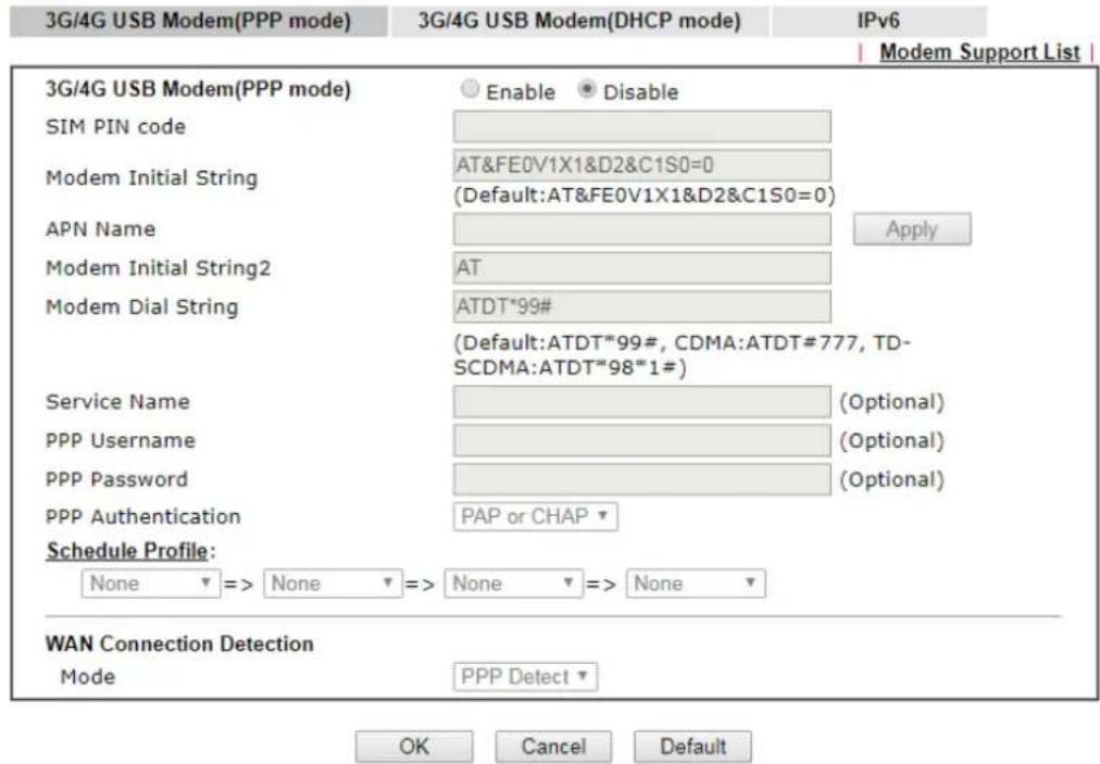
text_image
3G/4G USB Modem(PPP mode) 3G/4G USB Modem(DHCP mode) IPv6 Modem Support List 3G/4G USB Modem(PPP mode) Enable Disable SIM PIN code Modem Initial String AT&FE0V1X1&D2&C1S0=0 (Default:AT&FE0V1X1&D2&C1S0=0) APN Name Modem Initial String2 AT Apply Modem Dial String ATDT*99# (Default:ATDT*99#, CDMA:ATDT#777, TD- SCDMA:ATDT*98*1#) Service Name (Optional) PPP Username (Optional) PPP Password (Optional) PPP Authentication PAP or CHAP ▼ Schedule Profile: None => None => None => None ▼ WAN Connection Detection Mode PPP Detect ▼ OK Cancel DefaultAvailable settings are explained as follows:
| Item | Description | |||
| Modem Support List It lists | all of the modems supported by such router.192.168.L1@ce@ppomplatin | |||
| 3G/4G Modem Support List(PPP mode)The following compatibility test lists 3.5G/LTE modems supported by Viger router under certain environment or countries. If the LTE modem you have is on the list but cannot work properly, please write an e-mail to support@draytek.com or consult your dealer for further information. | ||||
| Brand | Model | LTE | Status | |
| 4G system | XSPlug P3 | Y | ||
| Alcatel | Alcatel L100V | Y | ||
| Alcatel | Alcatel X080S | Y | ||
| Alfa | ALFA Flyopp | Y | ||
| BandRich | Bandluxe C270 | Y | ||
| BandRich | Bandluxe C321 | Y | ||
| BandRich | Bandluxe C330 | Y | ||
| BandRich | Bandluxe C331 | Y | ||
| BandRich | Bandluxe C502 | Y | ||
| BigPond | BigPond Next G Wireless | Y | ||
| D-Link | D_LINK DWM222 | Y | ||
| 3G /4G USB Modem (PPP mode) | Click Enable for activating this function. If you click Disable, this function will be closed and all the settings that you adjusted in this page will be invalid. | |||
| SIM PIN code | Type PIN code of the SIM card that will be used to access Internet.The maximum length of the PIN code you can set is 15 | |||
| characters. | ||||
| Modem Initial String Such value is used to initialize USB modem. Please use the default value. If you have any question, please contact to your ISP.The maximum length of the string you can set is 47 characters. | ||||
| APN Name APN means Access Point Name which is provided and required by some ISPs. Enter the name and clickApply.The maximum length of the name you can set is 43 characters. | ||||
| Modem Initial String2 The initial string 1 is shared with APN.In some cases, user may need another initial AT command to restrict 3G band or do any special settings.The maximum length of the string you can set is 47 characters. | ||||
| Modem Dial String | Such value is used to dial through USB mode. Please use the default value. If you have any question, please contact to your ISP.The maximum length of the string you can set is 31 characters. | |||
| Service Name Enter the description of the specific network service. | ||||
| PPP Username Enter the PPP username (optional). The maximum length of the name you can set is 63 characters. | ||||
| PPP Password Enter the PPP password (optional). The maximum length of the password you can set is 62 characters. | ||||
| PPP Authentication | Select PAP only or PAP or CHAP for PPP. | |||
| Schedule Profile You can type in four sets of time schedule for your request.All the schedules can be set previously inApplication >>Scheduleweb page and you can use the number that you have set in that web page | ||||
| WAN Connection Detection | Such function allows you to verify whether network connection is alive or not through PPP Detect or Ping Detect.Mode - Choose PPP Detect or Ping Detectfor the system to execute for WAN detection. If you choose Ping Detect as the detection mode, you have to type required settings for the following items.Primary/Secondary Ping IP - If you choose Ping Detectas detection mode, you have to type Primary or Secondary IP address in this field for pinging.Ping Gateway IP - If you choose Ping Detectas detection mode, you also can enable this setting to use current WAN gateway IP address for pinging.With the IP address(es) pinging, Vigor router can check if the WAN connection is on or off.TTL (Time to Live) - Set TTL value of PING operation.Ping Interval - Enter the interval for the system to execute the PING operation.Ping Retry - Enter the number of times that the system is allowed to execute the PING operation before WAN disconnection is judged. | |||
After finishing all the settings here, please click OK to activate them.
II-1-2-5 Details Page for 3G/4G USB Modem (DHCP mode) in WAN3/WAN4
To use 3G/4G USB Modem (DHCP mode) as the accessing protocol of the internet, please choose Internet Access from WAN menu. Then, select 3G/4G USB Modem (DHCP mode) for WAN3/WAN4. The following web page will be shown.
WAN >> Internet Access

WAN 3
3G/4G USB Modem(PPP mode)
3G/4G USB Modem(DHCP mode)
IPv6
Modem Support List
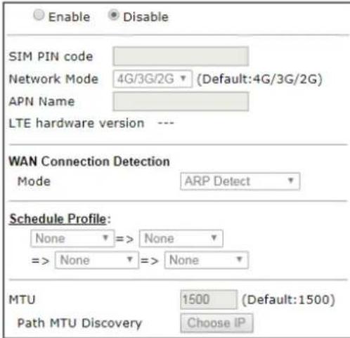
text_image
Enable Disable SIM PIN code Network Mode 4G/3G/2G (Default:4G/3G/2G) APN Name LTE hardware version --- WAN Connection Detection Mode ARP Detect Schedule Profile: None => None => None => None MTU 1500 (Default:1500) Path MTU Discovery Choose IP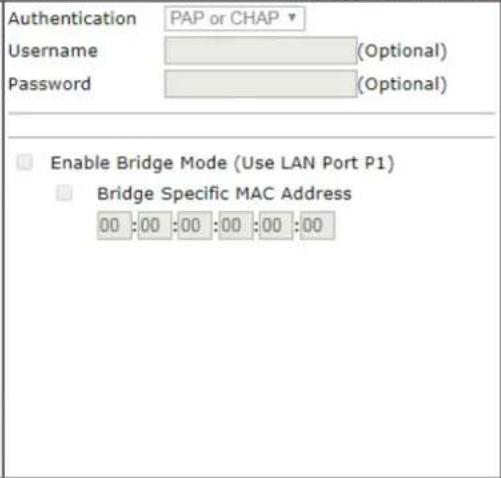
text_image
Authentication PAP or CHAP Username (Optional) Password (Optional) Enable Bridge Mode (Use LAN Port P1) Bridge Specific MAC Address 00:00:00:00:00:00Note:
- Please note that in some case USB port connection will be terminated temporarily to activate the new configuration.
- VPN feature may be affected when the value of MTU is changed, please also check your value of VPN mss by using "VPN mss set" command. We recommend to put the same decreased value on VPN mss. For example, reducing the MTU from 1500 - > 1400, then it will need to reduct 100 from mss value.

Available settings are explained as follows:
| Item | Description |
| Modem Support List It lists | all of the modems supported by such router. |
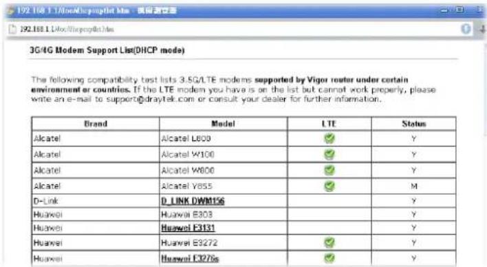 | |
| Enable / Disable | Click Enable for activating this function. If you click Disable, this function will be closed and all the settings that you adjusted in this page will be invalid. |
| SIM PIN code | Type PIN code of the SIM card that will be used to access Internet.The maximum length of the PIN code you can set is 19 characters. |
| Network Mode | Force Vigor router to connect Internet with the mode specified here. If you choose 4G/3G/2G as network mode, the router will choose a suitable one according to the actual wireless signal automatically. |
| APN Name APN means Access Point Name which is provided and required by some ISPs. Enter the name and clickApply.The maximum length of the name you can set is 47 characters. | |
| WAN Connection Detection | Such function allows you to verify whether network connection is alive or not through ARP Detect or Ping Detect.Mode - ChooseARP DetectorPing Detectfor the system to execute for WAN detection. If you choose Ping Detect as the detection mode, you have to type required settings for the following items.Primary/Secondary Ping IP - If you choose Ping Detectas detection mode, you have to type Primary or Secondary IP address in this field for pinging.Ping Gateway IP - If you choose Ping Detectas detection mode, you also can enable this setting to use current WAN gateway IP address for pinging.With the IP address(es) pinging, Vigor router can check if the WAN connection is on or off.TTL (Time to Live) - Set TTL value of PING operation.Ping Interval - Enter the interval for the system to execute the PING operation.Ping Retry - Enter the number of times that the system is allowed to execute the PING operation before WAN disconnection is judged. |
| Schedule Profile You can type in four sets of time schedule for your request.All the schedules can be set previously inApplication >>Scheduleweb page and you can use the number that you have set in that web page | |
| MTU It means Max Transmit | Unit for packet.Path MTU Discovery- It is used to detect the maximum MTU size of a packet not to be segmented in specific transmit path.Click Choose IP to open the following dialog.172.17.11.1/doc/pathmtu.htmPath MTU to:IPv4 HostMTU reduce size by8DetectNote:You may reduce the Path MTU Size(max 1500) by 1 to 100.Accept CancelPath MTU to - Enter the IP address as the specific transmit path.MTU reduce size by- It determines the decreasing size of MTU value. For example, the number specified in this field is “8”. The maximum MTU size is “1500”. After clicking the “detect” button, the system will calculate and get the suitable MTU value such as 1500, 1492, 1484 and etc., automatically.Detect - Click it to detect a suitable MTU valueAccept - After clicking it, the detected value will be displayed in the field of MTU. |
| Authentication | Select PAP only or PAP or CHAP for PPP authentication.Usage - Enter the username for authentication (optional).Password - Enter the password for authentication (optional). |
| Enable Bridge Mode | If the function is enabled, the router will work as a bridge modem. Yet, the incoming packets with VLAN tags will be discarded.Bridge Specific MAC Address - Some Cable service providers specify a specific MAC address for access authentication. In such cases you need to check the box and enter the MAC address in the MAC Address field. |
After finishing all the settings here, please click OK to activate them.
II-1-2-6 Details Page for 3G/4G USB Modem (DHCP mode) in LTE WAN
It is available for "L" model only. LTE WAN uses the embedded LTE module to access internet.
To use 3G/4G USB Modem (DHCP mode) as the accessing protocol of the internet, please choose Internet Access from WAN menu. Then, select 3G/4G USB Modem (DHCP mode) for LTE. The following web page will be shown.
LTE
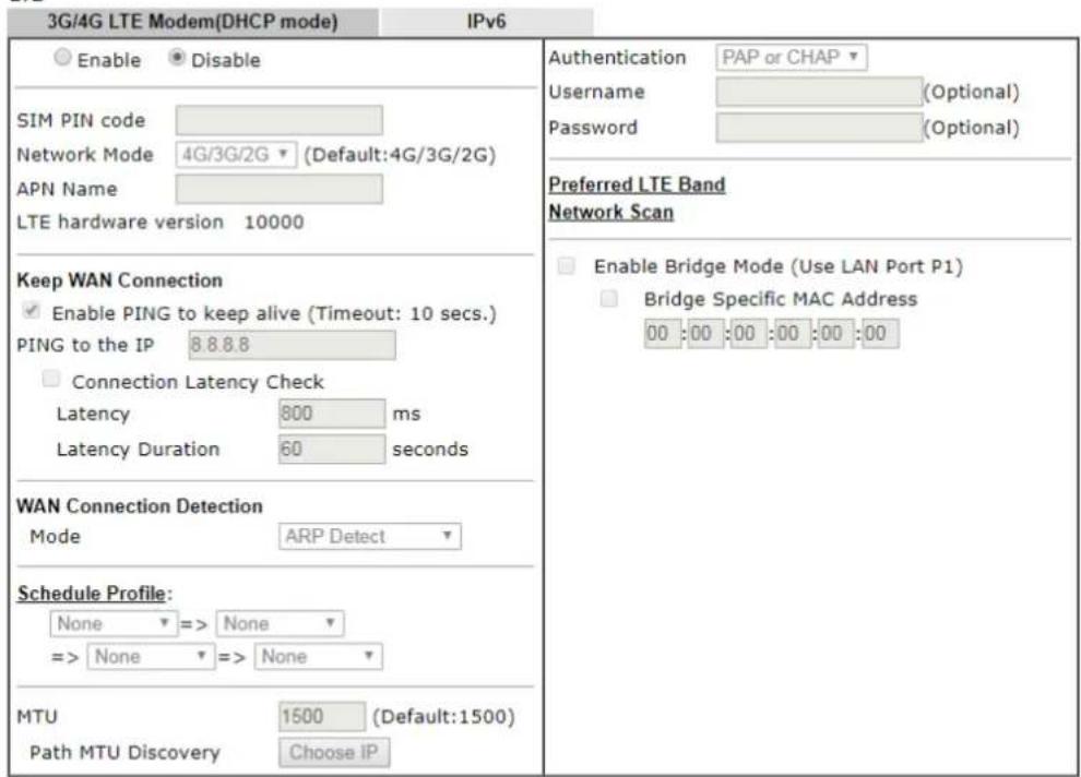
text_image
3G/4G LTE Modem(DHCP mode) IPv6 Enable Disable SIM PIN code Network Mode 4G/3G/2G (Default:4G/3G/2G) APN Name LTE hardware version 10000 Keep WAN Connection Enable PING to keep alive (Timeout: 10 secs.) PING to the IP 8.8.8.8 Connection Latency Check Latency 800 ms Latency Duration 60 seconds WAN Connection Detection Mode ARP Detect Schedule Profile: None => None => None => None MTU 1500 (Default:1500) Path MTU Discovery Choose IP Authentication PAP or CHAP Username (Optional) Password (Optional) Preferred LTE Band Network Scan Enable Bridge Mode (Use LAN Port P1) Bridge Specific MAC Address 00 :00 :00 :00 :00 :00Note:
- Please note that in some case USB port connection will be terminated temporarily to activate the new configuration.
- Preferred LTE band setting will take effect until next LTE connection.
- VPN feature may be affected when the value of MTU is changed, please also check your value of VPN mss by using "VPN mss set" command.
We recommend to put the same decreased value on VPN mss. For example, reducing the MTU from 1500 - > 1400, then it will need to reduct 100 from mss value.
Available settings are explained as follows:
| Item | Description |
| Enable | Click Enable for activating this function. If you click Disable, this function will be closed and all the settings that you adjusted in this page will be invalid. |
| SIM PIN code | Type PIN code of the SIM card that will be used to access Internet.The maximum length of the PIN code you can set is 19 characters. |
| Network Mode | Force Vigor router to connect Internet with the mode specified here. If you choose 4G/3G/2G as network mode, the router will choose a suitable one according to the actual wireless signal automatically. |
| APN Name APN means Access | Point Name which is provided and required by some ISPs. Enter the name and click Apply.The maximum length of the name you can set is 47 characters. |
| LTE hardware version The | hardware version of the embedded LTE module. |
| Keep WAN Connection | Normally, this function is designed for Dynamic IP environments because some ISPs will drop connections if there is no traffic within certain periods of time. Check Enable PING to keep alive box to activate this function.Enable PING to Keep alive - If you enable the PING function, please specify an IP address for the system to PING it for keeping alive. Vigor system will send a packet per second to the specified IP address. If the system does not receive any reply from that IP within 10 seconds, Vigor system will reboot LTE module until successfully set LTE connection.PING to the IP - Enter an IP address.Connection Latency Check - Enable the latency time setting for packet reply. If it is enabled (checked), Vigor system will wait for the packet reply from the specified IP address.When the time of waiting packet reply reaches the time threshold (defined in Latency) and continues for a period of time (defined in Latency Duration), Vigor system will reboot LTE module until successfully set LTE connection.Latency - Set a time threshold for packet reply. Default value is 800 (unit: micro-second).Latency Duration - Set a time period. Default value is 60 (unit: second). |
| WAN Connection Detection | Such function allows you to verify whether network connection is alive or not through ARP Detect or Ping Detect.Mode - Choose ARP Detect or Ping Detect for the system to execute for WAN detection. If you choose Ping Detect as the detection mode, you have to type required settings for the following items.Primary/Secondary Ping IP - If you choose Ping Detect as detection mode, you have to type Primary or Secondary IP address in this field for pinging.Ping Gateway IP - If you choose Ping Detect as detection mode, you also can enable this setting to use current WAN gateway IP address for pinging.With the IP address(es) pinging, Vigor router can check if the WAN connection is on or off.TTL (Time to Live) - Set TTL value of PING operation.Ping Interval - Enter the interval for the system to execute the PING operation.Ping Retry - Enter the number of times that the system is allowed to execute the PING operation before WAN disconnection is judged. |
| Schedule Profile Set the LTE | WAN to work at certain time interval only. You may choose up to 4 schedules out of the 15 schedules pre-defined in Applications >> Schedule setup. The default setting of this field is blank and the function will always work. |
| MTU It means Max Transmit | Unit for packet.Path MTU Discovery - It is used to detect the maximum MTU size of a packet not to be segmented in specific transmit path.Click Choose IP to open the following dialog. |
  MTU reduce size by MTU reduce size by  Note: You may reduce the Path MTU Size(max 1500) by 1 to 100.Accept CancelPath MTU to - Enter the IP address as the specific transmit path.MTU reduce size by - It determines the decreasing size of MTU value. For example, the number specified in this field is “8”. The maximum MTU size is “1500”. After clicking the “detect” button, the system will calculate and get the suitable MTU value such as 1500, 1492, 1484 and etc., automatically.Detect - Click it to detect a suitable MTU value.Accept - After clicking it, the detected value will be displayed in the field of MTU. Note: You may reduce the Path MTU Size(max 1500) by 1 to 100.Accept CancelPath MTU to - Enter the IP address as the specific transmit path.MTU reduce size by - It determines the decreasing size of MTU value. For example, the number specified in this field is “8”. The maximum MTU size is “1500”. After clicking the “detect” button, the system will calculate and get the suitable MTU value such as 1500, 1492, 1484 and etc., automatically.Detect - Click it to detect a suitable MTU value.Accept - After clicking it, the detected value will be displayed in the field of MTU. | |
| Authentication | Select None or PAP or CHAP. |
| UserName Enter the username (optional). The maximum length of the name you can set is 47 characters. | |
| Password Enter the password (optional). The maximum length of the password you can set is 62 characters. | |
| Preferred LTE Band | Click the link to specify the preferred LTE band. A dialog will be open and list available LTE bands supported by the LTE module for the user to choose for establishing the network connection. |
| Network Scan | Click it to search the nearby ISP for LTE connection.The following dialog lists available ISP services detected by Vigor router. |
| Enable Bridge Mode | If the function is enabled, the router will work as a LTE bridge modem.Bridge Specific MAC Address - Enter the MAC address of the device (e.g., a computer, router or a WiFi router) which needs to be connected to the Internet through the LTE modem. |
After finishing all the settings here, please click OK to activate them.
II-1-2-7 Details Page for IPv6 – Offline in WAN1/WAN2/WAN3/WAN4
When Offline is selected, the IPv6 connection will be disabled.
WAN >> Internet Access

WAN 1

text_image
PPPoE Static or Dynamic IP PPTP/L2TP IPv6 Internet Access Mode Connection Type Offline ▼
II-1-2-8 Details Page for IPv6 – PPP in WAN1/WAN2
During the procedure of IPv4 PPPoE connection, we can get the IPv6 Link Local Address between the gateway and Vigor router through IPv6CP. Later, use DHCPv6 or accept RA to acquire the IPv6 prefix address (such as: 2001:B010:7300:200::/64) offered by the ISP. In addition, PCs under LAN also can have the public IPv6 address for Internet access by means of the generated prefix.
No need to type any other information for PPP mode.
WAN >> Internet Access

WAN 1
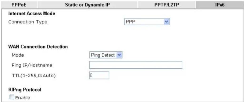
text_image
PPPoE Static or Dynamic IP PPTP/L2TP IPv6 Internet Access Mode Connection Type PPP WAN Connection Detection Mode Ping Detect Ping IP/Hostname TTL(1-255,0:Auto) 0 RIPng Protocol EnableNote:
IPv4 WAN setting should be PPPoE / PPPoA client.

Available settings are explained as follows:
| Item | Description |
| WAN Connection Detection | Such function allows you to verify whether network connection is alive or not through Ping Detect. Mode - Choose Always On or Ping Detect for the system to execute for WAN detection. Always On means no detection will be executed. The network connection will be on always.● Ping IP/Hostname - If you choose Ping Detect as detection mode, you have to type IP address in this field for pinging.● TTL (Time to Live) -If you choose Ping Detect as detection mode, you have to type TTL value. |
| RIPng Protocol RIPng (RIP next generation) offers the same functions and benefits as IPv4 RIP v2. | |
Below shows an example for successful IPv6 connection based on PPP mode.
Online Status
| Physical Connection | System Uptime: 0:2:32 | |||
| IPv4 | IPv6 | |||
| LAN Status | ||||
| IP Address | ||||
| 2001:B010:7300:201:21D:AAFF:FEA6:2568/64 (Global) | ||||
| FE80::21D:AAFF:FEA6:2568/64 (Link) | ||||
| TX Packets | RX Packets | TX Bytes | RX Bytes | |
| 7 | 4 | 690 | 328 | |
| WAN2 IPv6 Status | >> Drop PPP | |||
| Enable | Mode | Up Time | ||
| Yes | PPP | 0:02:08 | ||
| IP | Gateway IP | |||
| 2001:B010:7300:201:21D:AAFF:FEA6:256A/128 (Global) | FE80::90:1A00:242:AD52 | |||
| FE80::1D:AAFF:FEA6:256A/128 (Link) | ||||
| DNS IP | ||||
| 2001:B000:168::1 | ||||
| 2001:B000:168::2 | ||||
| TX Packets | RX Packets | TX Bytes | RX Bytes | |
| 7 | 9 | 544 | 1126 | |

Info
At present, the IPv6 prefix can be acquired via the PPPoE mode connection which is available for the areas such as Taiwan (hinet), the Netherlands, Australia and UK.
II-1-2-9 Details Page for IPv6 – TSPC in WAN1/WAN2/WAN3/WAN4
Tunnel setup protocol client (TSPC) is an application which could help you to connect to IPv6 network easily.
Please make sure your IPv4 WAN connection is OK and apply one free account from hexago (http://gogonet.gogo6.com/page/freenet6-account) before you try to use TSPC for network connection. TSPC would connect to tunnel broker and requests a tunnel according to the specifications inside the configuration file. It gets a public IPv6 IP address and an IPv6 prefix from the tunnel broker and then monitors the state of the tunnel in background.
After getting the IPv6 prefix and starting router advertisement daemon (RADVD), the PC behind this router can directly connect to IPv6 the Internet.
WAN 1
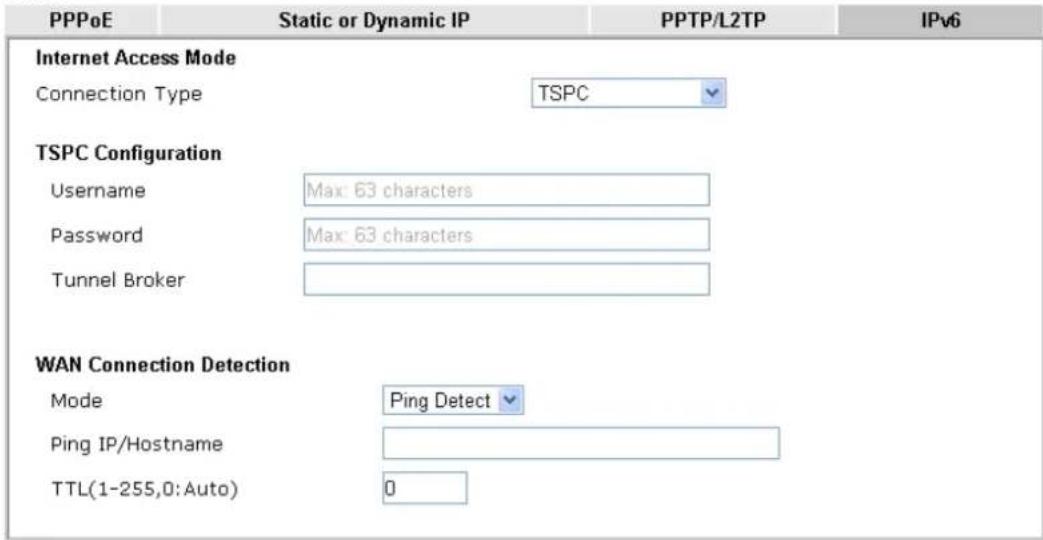
text_image
PPPoE Static or Dynamic IP PPTP/L2TP IPv6 Internet Access Mode Connection Type TSPC TSPC Configuration Username Max: 63 characters Password Max: 63 characters Tunnel Broker WAN Connection Detection Mode Ping Detect Ping IP/Hostname TTL(1-255,0:Auto) 0
Available settings are explained as follows:
| Item | Description |
| Username Enter the name of | obtained from the broker. It is suggested for you to apply another username and password for http://gogonet.gogo6.com/page/freenet6-account.The maximum length of the name you can set is 63 characters. |
| Password Enter the password | assigned with the user name.The maximum length of the name you can set is 19 characters. |
| Tunnel Broker | Enter the address for the tunnel broker IP, FQDN or an optional port number. |
| WAN Connection Detection | Such function allows you to verify whether network connection is alive or not through Ping Detect.Mode - Choose Always On or Ping Detect for the system to execute for WAN detection. Always On means no detection will be executed. The network connection will be on always.Ping IP/Hostname - If you choose Ping Detect as detection mode, you have to type IP address in this field for pinging.TTL (Time to Live) -If you choose Ping Detect as detection mode, you have to type TTL value. |
After finished the above settings, click OK to save the settings.
II-1-2-10 Details Page for IPv6 – AICCU in WAN1/WAN2/WAN3/WAN4
WAN >> Internet Access

WAN 1
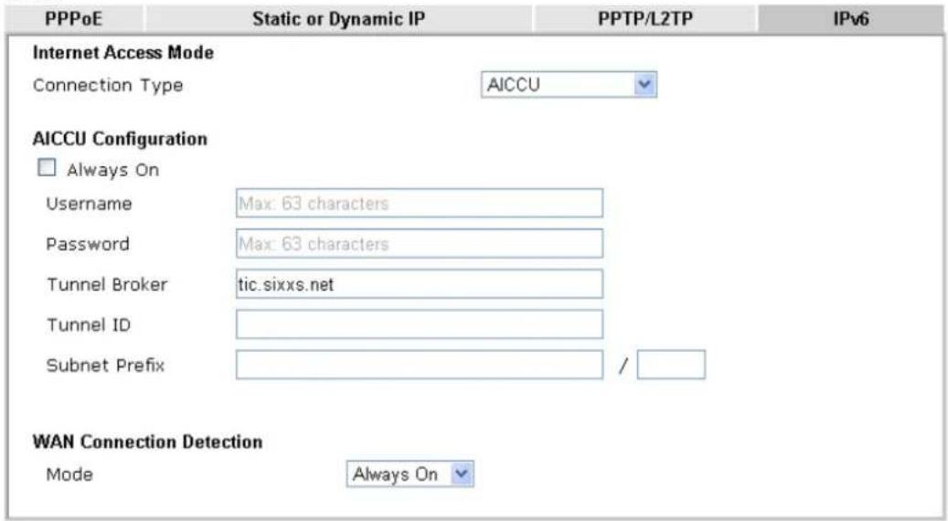
text_image
PPPoE Static or Dynamic IP PPTP/L2TP IPv6 Internet Access Mode Connection Type AICCU AICCU Configuration □ Always On Username Max: 63 characters Password Max: 63 characters Tunnel Broker tic.sixxs.net Tunnel ID Subnet Prefix / WAN Connection Detection Mode Always OnNote:
If "Always On" is not enabled, AICCU connection would only retry three times.

Available settings are explained as follows:
| Item | Description |
| Always On Check this box to | keep the network connection always. |
| Username Enter the name obtained from the broker. Please apply new account at http://www.sixxs.net/. It is suggested for you to apply another username and password.The maximum length of the name you can set is 19 characters. | |
| Password Enter the password assigned with the user name.The maximum length of the password you can set is 19 characters. | |
| Tunnel Broker It means a server of AICCU. The server can provide IPv6 tunnels to sites or end users over IPv4.Enter the address for the tunnel broker IP, FQDN or an optional port number. | |
| Tunnel ID One user account may have several tunnels. And, each tunnel shall have one specified tunnel ID (e.g., T115394).Enter the ID offered by Tunnel Broker. | |
| Subnet Prefix Enter the subnet prefix address obtained from service provider.The maximum length of the prefix you can set is 128 characters. | |
| WAN Connection Detection | Such function allows you to verify whether network connection is alive or not through Ping Detect. Mode - Choose Always On or Ping Detect for the system to execute for WAN detection.● Ping IP/Hostname - If you choose Ping Detect as detection mode, you have to type IP address in this field for pinging.● TTL (Time to Live) -If you choose Ping Detect as detection mode, you have to type TTL value. |
After finished the above settings, click OK to save the settings.
II-1-2-11 Details Page for IPv6 – DHCPv6 Client in WAN1/WAN2
DHCPv6 client mode would use DHCPv6 protocol to obtain IPv6 address from server.
WAN >> Internet Access

WAN 1
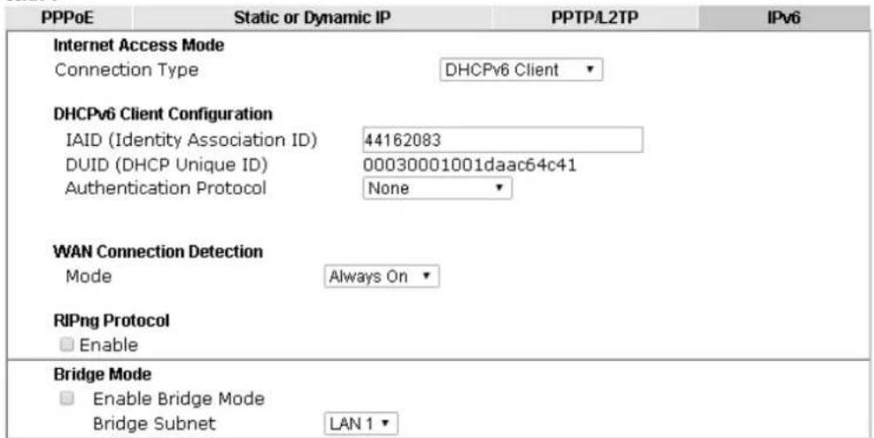
text_image
PPPoE Static or Dynamic IP PPTP/L2TP IPv6 Internet Access Mode Connection Type DHCPv6 Client DHCPv6 Client Configuration IAID (Identity Association ID) 44162083 DUID (DHCP Unique ID) 00030001001daac64c41 Authentication Protocol None WAN Connection Detection Mode Always On RIPng Protocol Enable Bridge Mode Enable Bridge Mode Bridge Subnet LAN 1
Available settings are explained as follows:
| Item | Description |
| IAID Type a number as IAID. | |
| WAN Connection Detection | Such function allows you to verify whether network connection is alive or not through NS Detect or Ping Detect. Mode - Choose Always On, Ping Detect or NS Detect for the system to execute for WAN detection. With NS Detect mode, the system will check if network connection is established or not, like IPv4 ARP Detect. Always On means no detection will be executed. The network connection will be on always.● Ping IP/Hostname - If you choose Ping Detect as detection mode, you have to type IP address in this field for pinging.● TTL (Time to Live) -If you choose Ping Detect as detection mode, you have to type TTL value. |
| RIPng Protocol RIPng (RIP next generation) offers the same functions and benefits as IPv4 RIP v2. | |
| Bridge Mode Enable Bridge | Mode - If the function is enabled, the router will work as a bridge modem. Enable Firewall - It is available when Bridge Mode is enabled. When both Bridge Mode and Firewall check boxes are enabled, the settings configured (user profiles) under User Management will be ignored. And all of the filter rules defined and enabled in Firewall menu will be activated.Bridge Subnet - Make a bridge between the selected LAN subnet and such WAN interface. |
After finished the above settings, click OK to save the settings.
II-1-2-12 Details Page for IPv6 – Static IPv6 in WAN1/WAN2
This type allows you to setup static IPv6 address for WAN interface.
WAN >> Internet Access

WAN 1
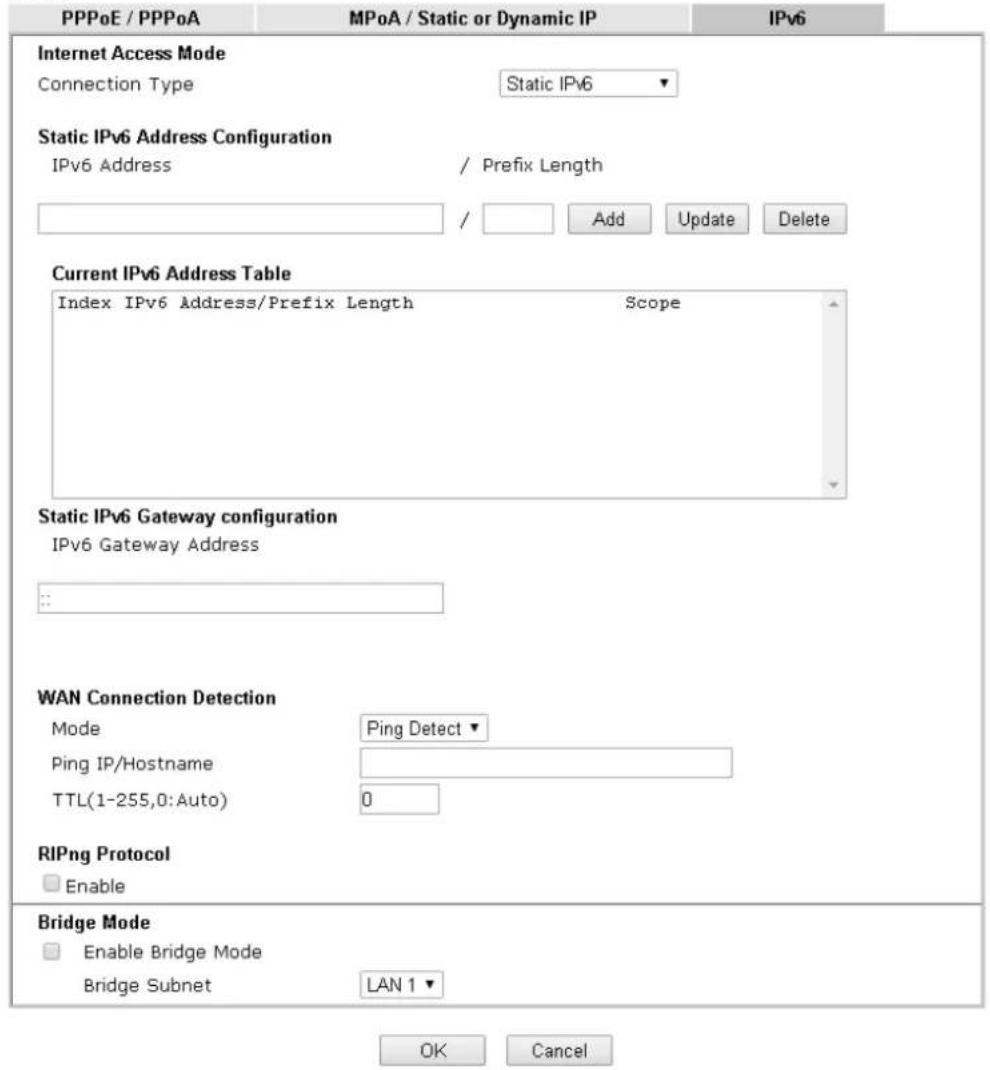
text_image
PPPoE / PPPoA MPoA / Static or Dynamic IP IPv6 Internet Access Mode Connection Type Static IPv6 Static IPv6 Address Configuration IPv6 Address / Prefix Length Add Update Delete Current IPv6 Address Table Index IPv6 Address/Prefix Length Scope Static IPv6 Gateway configuration IPv6 Gateway Address WAN Connection Detection Mode Ping Detect Ping IP/Hostname TTL(1-255,0:Auto) 0 RIPng Protocol Enable Bridge Mode Enable Bridge Mode Bridge Subnet LAN 1 ▼ OK CancelAvailable settings are explained as follows:
| Item | Description |
| Static IPv6 Address configuration | IPv6 Address - Enter the IPv6 Static IP AddressPrefix Length - Enter the fixed value for prefix length.Add - Click it to add a new entry.Update - Click it to modify an existed entry.Delete - Click it to remove an existed entry. |
| Current IPv6 Address Table | Display current interface IPv6 address. |
| Static IPv6 Gateway Configuration | IPv6 Gateway Address - Type your IPv6 gateway address here. |
| WAN Connection Such function allows you to verify whether network | |
| Detection connection is alive or not through Ping Detect. | |
| Mode - Choose Always On or Ping Detect for the system to execute for WAN detection. Always On means no detection will be executed. The network connection will be on always.● Ping IP/Hostname - If you choose Ping Detect as detection mode, you have to type IP address in this field for pinging.● TTL (Time to Live) -If you choose Ping Detect as detection mode, you have to type TTL value. | |
| Bridge Mode Enable Bridge | Mode - If the function is enabled, the router will work as a bridge modem.Enable Firewall - It is available when Bridge Mode is enabled. When both Bridge Mode and Firewall check boxes are enabled, the settings configured (user profiles) under User Management will be ignored. And all of the filter rules defined and enabled in Firewall menu will be activated.Bridge Subnet - Make a bridge between the selected LAN subnet and such WAN interface. |
After finished the above settings, click OK to save the settings.
II-1-2-13 Details Page for IPv6 – 6in4 Static Tunnel in WAN1/WAN2
This type allows you to setup 6in4 Static Tunnel for WAN interface.
Such mode allows the router to access IPv6 network through IPv4 network.
However, 6in4 offers a prefix outside of 2002::0/16. So, you can use a fixed endpoint rather than anycast endpoint. The mode has more reliability.
WAN >> Internet Access

WAN 1
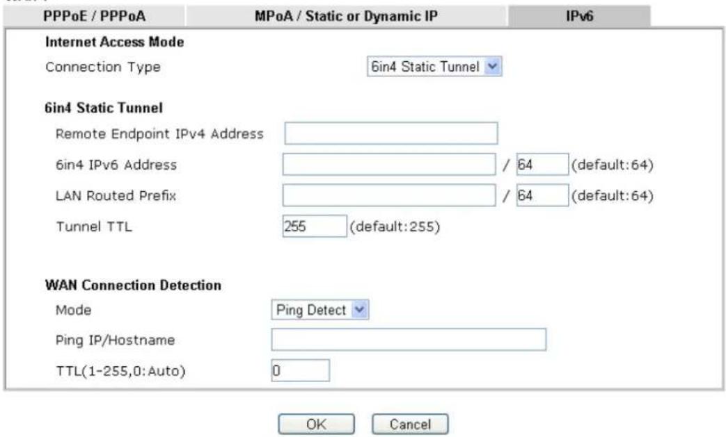
text_image
PPPoE / PPPoA MPoA / Static or Dynamic IP IPv6 Internet Access Mode Connection Type 6in4 Static Tunnel 6in4 Static Tunnel Remote Endpoint IPv4 Address 6in4 IPv6 Address / 64 (default:64) LAN Routed Prefix / 64 (default:64) Tunnel TTL 255 (default:255) WAN Connection Detection Mode Ping Detect Ping IP/Hostname TTL(1-255,0:Auto) 0 OK CancelAvailable settings are explained as follows:
| Item | Description |
| Remote Endpoint IPv4 Address | Enter the static IPv4 address for the remote server. |
| 6in4 IPv6 Address Enter the | static IPv6 address for IPv4 tunnel with the value for prefix length. |
| LAN Routed Prefix Enter the | static IPv6 address for LAN routing with the value for prefix length. |
| Tunnel TTL Enter the number | for the data lifetime in tunnel. |
| WAN Connection Detection | Such function allows you to verify whether network connection is alive or not through Ping Detect.Mode - Choose Always On or Ping Detect for the system to execute for WAN detection. Always On means no detection will be executed. The network connection will be on always.Ping IP/Hostname - If you choose Ping Detect as detection mode, you have to type IP address in this field for pinging.TTL (Time to Live) -If you choose Ping Detect as detection mode, you have to type TTL value. |
After finished the above settings, click OK to save the settings.
Below shows an example for successful IPv6 connection based on 6in4 Static Tunnel mode.
Online Status
| Physical Connection | System Uptime: 0day 0:4:16 | ||
| IPv4 | IPv6 | ||
| LAN Status | |||
| IP Address | |||
| 2001:4DD0:FF00:83E4:21D:AAFF:FE83:11B4/64 (Global) | |||
| FE80::21D:AAFF:FE83:11B4/64 (Link) | |||
| TX Packets | RX Packets | TX Bytes | RX Bytes |
| 14 | 80 | 1244 | 6815 |
| WAN1 IPv6 Status | |||
| Enable | Mode | Up Time | |
| Yes | 6in4 Static Tunnel | 0:04:07 | |
| IP | Gateway IP | ||
| 2001:4DD0:FF10:83E4::2131/64 (Global) | - - - | ||
| FE80::C0A8:651D/128 (Link) | |||
| TX Packets | RX Packets | TX Bytes | RX Bytes |
| 3 | 26 | 211 | 2302 |
II-1-2-14 Details Page for IPv6 – 6rd in WAN1/WAN2
This type allows you to setup 6rd for WAN interface.
WAN >> Internet Access

WAN 1
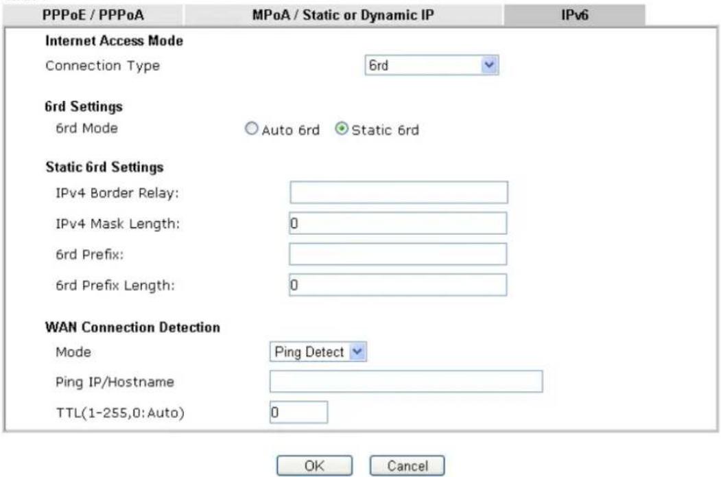
text_image
PPPoE / PPPoA MPoA / Static or Dynamic IP IPv6 Internet Access Mode Connection Type 6rd 6rd Settings 6rd Mode Auto 6rd Static 6rd Static 6rd Settings IPv4 Border Relay: IPv4 Mask Length: 0 6rd Prefix: 6rd Prefix Length: 0 WAN Connection Detection Mode Ping Detect Ping IP/Hostname TTL(1-255,0: Auto) 0 OK CancelAvailable settings are explained as follows:
| Item | Description |
| 6rd Mode Auto 6rd - Retrieve | ve 6rd prefix automatically from 6rd service provider. The IPv4 WAN must be set as "DHCP". Static 6rd - Set 6rd options manually. |
| IPv4 Border Relay Enter the | IPv4 addresses of the 6rd Border Relay for a given 6rd domain. |
| IPv4 Mask Length Type a num | number of high-order bits that are identical across all CE IPv4 addresses within a given 6rd domain.It may be any value between 0 and 32. |
| 6rd Prefix Enter the 6rd IPv6 address. | |
| 6rd Prefix Length Enter the | IPv6 prefix length for the 6rd IPv6 prefix in number of bits. |
| WAN Connection Detection | Such function allows you to verify whether network connection is alive or not through Ping Detect.Mode - Choose Always On or Ping Detect for the system to execute for WAN detection. Always On means no detection will be executed. The network connection will be on always.Ping IP/Hostname - If you choose Ping Detect as detection mode, you have to type IP address in this field for pinging.TTL (Time to Live) -If you choose Ping Detect as detection mode, you have to type TTL value. |
After finished the above settings, click OK to save the settings.
Below shows an example for successful IPv6 connection based on 6rd mode.
Online Status
| Physical Connection | System Uptime: 0day 0:9:15 | |||
| IPv4 | IPv6 | |||
| LAN Status | ||||
| IP Address | ||||
| 2001:E41:A865:1D00:21D:AAFF:FE83:11B4/64 (Global) | ||||
| FE80::21D:AAFF:FE83:11B4/64 (Link) | ||||
| TX Packets | RX Packets | TX Bytes | RX Bytes | |
| 15 | 113 | 1354 | 18040 | |
| WAN1 IPv6 Status | ||||
| Enable | Mode | Up Time | ||
| Yes | 6rd | 0:09:06 | ||
| IP | Gateway IP | |||
| 2001:E41:A865:1D01:21D:AAFF:FE83:11B5/128(Global) | --- | |||
| FE80::C0A8:651D/128 (Link) | ||||
| TX Packets | RX Packets | TX Bytes | RX Bytes | |
| 13 | 29 | 967 | 2620 | |
II-1-3 Multi-VLAN
Multi-VLAN allows users to create profiles for specific WAN interface and bridge connections for user applications that require very high network throughput. Simply go to WAN and select Multi-VLAN.
Channel 1 to 4 have the following fixed assignments and cannot be altered.
● Channel 1: Ethernet on WAN1.
● Channel 2: Fiber on WAN2 / Ethernet on WAN2 (based on the model)
● Channel 3/4: USB1 (WAN3) and USB2 (WAN4), respectively.
Channels 5 through 10 can be bridged to one or more of the 3 LAN ports P2 through P4. In addition, Channels 5 through 7 can be configured as virtual WANs (WAN5 through WAN7).
General
This page shows the basic configurations used by every channel.
WAN >> Multi-VLAN

Multi-VLAN
| General | ||||
| Channel | Enable | WAN Type | VLAN Tag | Port-based Bridge |
| 1 | √ | Ethernet(WAN1) | None | |
| 2 | √ | Ethernet(WAN2) | None | |
| 5. WAN5 | □ | Ethernet(WAN1) | None | □ Enable □ P1 □ P2 □ P3 □ P4 |
| 6. WAN6 | □ | Ethernet(WAN1) | None | □ Enable □ P1 □ P2 □ P3 □ P4 |
| 7. WAN7 | □ | Ethernet(WAN1) | None | □ Enable □ P1 □ P2 □ P3 □ P4 |
| 8. | □ | Ethernet(WAN1) | None | □ Enable □ P1 □ P2 □ P3 □ P4 |
| 9. | □ | Ethernet(WAN1) | None | □ Enable □ P1 □ P2 □ P3 □ P4 |
| 10. | □ | Ethernet(WAN1) | None | □ Enable □ P1 □ P2 □ P3 □ P4 |
Note:
Channel 3 and channel 4 are reserved for USB WAN.

Available settings are explained as follows:
| Item | Description |
| Channel Display the number | of each channel.Channels 1 and 2 are used by the Internet Access web user interface and can not be configured here.Channels 5 ~ 10 are configurable. |
| Enable Display whether the | settings in this channel are enabled (Yes) or not (No). |
| WAN Type | Displays the physical medium that the channel will use. |
| VLAN Tag | Displays the VLAN tag value that will be used for the packets traveling on this channel. |
| Port-based Bridge The network traffic flowing on each channel will be identified by the system via their VLAN Tags. Channels using the same WAN type may not configure the same VLAN tag value.Enable - Check this box to enable the port-based bridge function on this channel.P1 ~ P4 - Check the box(es) to build bridge connection on LAN. |
To configure a PVC channel, click its channel number.
WAN links for Channel 5, 6 and 7 are provided for router-borne application such as TR-069. The settings must be applied and obtained from your ISP. For your special request, please contact with your ISP and then click WAN link of Channel 5, 6 or 7 to configure your router.
WAN >> Multi-VLAN >> Channel 5
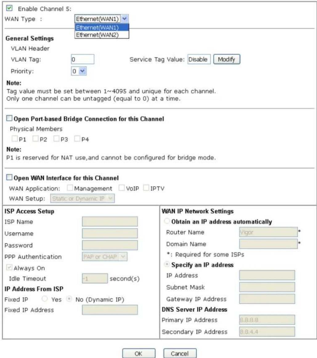
text_image
Enable Channel 5: WAN Type : Ethernet(WAN1) Ethernet(WAN1) Ethernet(WAN2) General Settings VLAN Header VLAN Tag: 0 Service Tag Value: Disable Modify Priority: 0 Note: Tag value must be set between 1~4095 and unique for each channel. Only one channel can be untagged (equal to 0) at a time. Open Port-based Bridge Connection for this Channel Physical Members P1 P2 P3 P4 Note: P1 is reserved for NAT use,and cannot be configured for bridge mode. Open WAN Interface for this Channel WAN Application: Management VoIP IPTV WAN Setup: Static or Dynamic IP ISP Access Setup ISP Name Username Password PPP Authentication Always On Idle Timeout -1 second(s) IP Address From ISP Fixed IP Yes No (Dynamic IP) Fixed IP Address WAN IP Network Settings Obtain an IP address automatically Router Name Vigor * Domain Name * *: Required for some ISPs Specify an IP address IP Address Subnet Mask Gateway IP Address DNS Server IP Address Primary IP Address 8.8.8.8 Secondary IP Address 8.8.4.4 OK CancelAvailable settings are explained as follows:
| Item | Description |
| Enable Channel 5/6/7 Check it to enable this channel. | |
WAN Type Specify a WAN type of the PVC Channel/VLAN.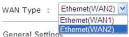 | |
| General Settings VLAN Tag | - Enter the value as the VLAN ID number. Valid settings are in the range from 1 to 4095. The network traffic flowing on each channel will be identified by the system via their VLAN Tags. Channels using the same WAN type may not configure the same VLAN tag value.Priority - Choose the number to determine the packet priority for such VLAN. The range is from 0 to 7.Service Tag Value - Such value varies depending on the setting configured in WAN>>General Setup. If required, click Modify to open WAN>>General Setup. Then, enable VLAN Tag insertion for service (outer tag) and specify the value as the VLAN ID number. Or, disable it. |
| Open Port-based Bridge Connection for this Channel | The settings here will create a bridge between the LAN ports selected and the WAN. The WAN interface of the bridge connection will be built upon the WAN type selected using the VLAN tag configured.Physical Members - Group the physical ports by checking the corresponding check box(es) for applying the port-based bridge connection.Note: LAN port P1 is reserved for NAT use and cannot be selected for bridging. |
| Open WAN Interface for this Channel | Check the box to enable relating function.WAN Application - Management can be specified for general management (Web configuration/telnet/TR069). If you choose Management, the configuration for this VLAN will be effective for Web configuration/telnet/TR069.IPTV - The IPTV configuration will allow the WAN interface to send IGMP packets to IPTV servers.WAN Setup - Choose PPPoE/PPPoA or Static or Dynamic IP to determine what WAN settings must be configured.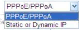 |
| ISP Access Setup Enter your | allocated username, password and authentication parameters according to the information provided by your ISP.ISP Name - PPP Service Name. Enter if your ISP requires this setting; otherwise leave blank.Usage - Name provided by the ISP for PPPoE/ PPPoA authentication. Maximum length is 62 characters.Password - Password provided by the ISP for PPPoE/ PPPoA authentication. Maximum length is 62 characters.PPP Authentication -The protocol used for PPPauthentication.PAP only- Only PAP (Password Authentication Protocol) is used.PAP or CHAP- Both PAP and CHAP(Challenge-Handshake Authentication Protocol) can be used for PPP authentication. Router negotiates with the PPTP or L2TP server to determine which protocol to use.Always On - If selected, the router will maintain the PPPoE/ PPPoA connection.Idle Timeout - Maximum length of time, in seconds, of idling allowed (no traffic) before the connection is dropped.IP Address From ISP - Specifies how the WAN IP address of the channel configured.Fixed IPYes - IP address entered in the Fixed IP Address field will be used as the IP address of the virtual WAN.No - Virtual WAN IP address will be assigned by the ISP's PPPoE/ PPPoA server. |
| WAN IP Network Settings | Obtain an IP address automatically - Select this option if the router is to receive IP configuration information from a DHCP server.Router Name - Sets the value of DHCP Option 12, which is used by some ISPs.Domain Name - Sets the value of DHCP Option 15, which is used by some ISPs.Specify an IP address - Select this option to manually enter the IP address.IP Address - Type in the IP address.Subnet Mask - Type in the subnet mask.Gateway IP Address - Type in gateway IP address.DNS Server IP Address - Type in the primary IP address for the router if you want to use Static IP mode. If necessary, type in secondary IP address for necessity in the future. |
After finished the above settings, click OK to save the settings and return to previous page. Click any index (8, 9 and 10) to get the following web page:
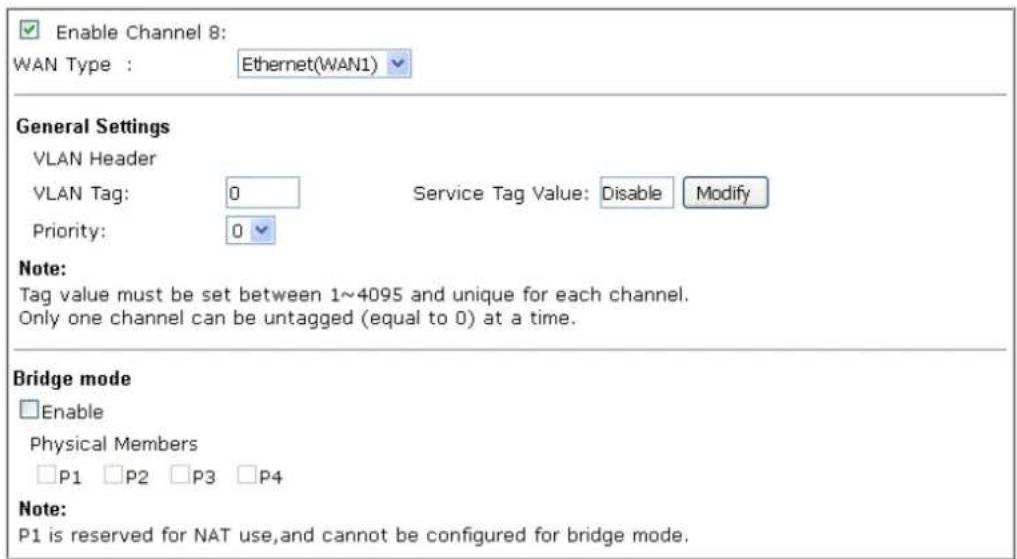
text_image
Enable Channel 8: WAN Type : Ethernet(WAN1) General Settings VLAN Header VLAN Tag: 0 Service Tag Value: Disable Modify Priority: 0 Note: Tag value must be set between 1~4095 and unique for each channel. Only one channel can be untagged (equal to 0) at a time. Bridge mode □Enable Physical Members □P1 □P2 □P3 □P4 Note: P1 is reserved for NAT use,and cannot be configured for bridge mode.
Available settings are explained as follows:
| Item | Description |
| Enable Channel 8/9/10 | Click it to enable the configuration of this channel. |
| WAN Type | The connections and interfaces created in every channel may select a specific WAN type to be built upon. In the Multi-VLAN application, only the Ethernet WAN type is available. The user will be able to select the physical WAN interface the channel shall use here. |
| General Settings VLAN Tag – | Enter the value as the VLAN ID number. Valid settings are in the range from 1 to 4095. The network traffic flowing on each channel will be identified by the system via their VLAN Tags. Channels using the same WAN type may not configure the same VLAN tag value.Priority – Choose the number to determine the packet priority for such VLAN. The range is from 0 to 7. |
| Bridge mode | Enable – Click it to enable Bridge mode for such channel.Physical Members – Group the physical ports by checking the corresponding check box(es) for applying the bridge connection.Note: LAN port P1 is reserved for NAT use and cannot be selected for bridging. |
After finished the above settings, click OK to save the settings.
II-1-4 WAN Budget
This function is used to determine the data traffic volume for each WAN interface respectively to prevent from overcharges for data transmission by the ISP. Please note that the Quota Limit and Billing cycle day of month settings will need to be configured correctly first in order for some period calculations to be performed correctly.
II-1-4-1 General Setup
WAN >> WAN Budget
| General Setup | Status | ||||
| Index | Enable | Quota | When quota exceeded | Time cycle | Duration |
| WAN1 | ☐ | OMB/OMB | 0/00/00 00:00~0/00/00 00:00 | ||
| WAN2 | ☐ | OMB/OMB | 0/00/00 00:00~0/00/00 00:00 | ||
| WAN3 | ☐ | OMB/OMB | 0/00/00 00:00~0/00/00 00:00 | ||
| WAN4 | ☐ | OMB/OMB | 0/00/00 00:00~0/00/00 00:00 | ||
Note:
- The budget traffic information provided here is for reference only, please consult your ISP for the actual traffic usage and charges.
- When hardware acceleration function is used, the monitored WAN traffic of Ethernet WAN interfaces may be slightly inaccurate.
OK Cancel
Or,
WAN >> WAN Budget
| General Setup | Status | ||||
| Index | Enable | Quota | When quota exceeded | Time cycle | Duration |
| WAN1 | OMB/OMB | 0/00/00 00:00~0/00/00 00:00 | |||
| WAN2 | OMB/OMB | 0/00/00 00:00~0/00/00 00:00 | |||
| LTE | OMB/OMB | 0/00/00 00:00~0/00/00 00:00 | |||
| WAN4 | OMB/OMB | 0/00/00 00:00~0/00/00 00:00 | |||
Note:
- The budget traffic information provided here is for reference only, please consult your ISP for the actual traffic usage and charges.
- When hardware acceleration function is used, the monitored WAN traffic of Ethernet WAN interfaces may be slightly inaccurate.
OK Cancel
| Item | Description |
| Index The WAN port. | Click to configure WAN Budget for a particular WAN. |
| Enable | v - WAN Budget is enabled on this WAN.x - WAN Budget is disabled on this WAN. |
| Quota | The current cycle's Internet usage is expressed as x/y where x is the cumulative usage and y is the upper limit. For example, 100MB/200MB means the usage thus far in this cycle is 100MB, and the upper limit is 200MB. |
| When quota exceeded Actions to be taken once the quota is reached.Shutdown - WAN will be disabled.Mail Alert - Email will be sent to the administrator. | |
| Time cycle Reset frequency of the usage data.Monthly - The Monthly option in the Criterion and Action | |
| tab was used to set up the usage quota.User Defined: The User Defined option in the Criterion and Action tab was used to set up the usage qota. | |
Duration Start and end timestamps of the current cycle.
Click WAN1/ WAN2/ WAN3 or LTE/ WAN4 link to open the following web page.
WAN >> WAN Budget
WAN 1
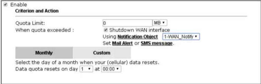
text_image
Enable Criterion and Action Quota Limit: 0 MB When quota exceeded : ✓ Shutdown WAN interface Using Notification Object 1-WAN_Notify Set Mail Alert or SMS message. Monthly Custom Select the day of a month when your (cellular) data resets. Data quota resets on day 1 at 00:00Note:
- Please make sure the Time and Date of the router is configured.
- SMS message and mail will be sent when the usage reaches 95% and 100% of quota.
OK Cancel
Available settings are explained as follows:
| Item | Description |
| Enable Check the box to enable such function. | |
| Quota Limit Enter the data traffic quota allowed for such WAN interface.There are two unit (MB and GB) offered for you to specify. | |
| When quota exceeded Check the box(es) as the condition(s) for the system to perform when the traffic has exceeded the budget limit.Shutdown WAN interface - All the outgoing traffic through such WAN interface will be terminated.Using Notification Object - The system will send out a notification based on the content of the notification object.Set Mail Alert - The system will send out a warning message to the administrator when the quota is running out. However, the connection charges will be calculated continuously.Set SMS message - The system will send out SMS message to the administrator when the quota is running out. | |
| Monthly Some ISP might apply for the network limitation based on the traffic limit per month. This setting is to offer a mechanism of resetting the traffic record every month.Monthly CustomSelect the day of a month when your (cellular) data resets.Data quota resets on day 1 at 00:00Data quota resets on day ... - You can determine the starting day in one month. | |
| Custom | This setting allows the user to define the billing cycle according to his request. The WAN budget will be reset with an interval of billing cycle.Monthly is default setting. If long period or a short period is required, useCustom. The period of cycle duration is between 1 day and 60 days. You can determine the cycle duration by specifying the days and the hours. In addition, you can specify which day of today is in a cycle.Use Cycle in hours - Monthly CustomUse Cycle in hoursUse Cycle in daysUsage counter resets at the beginning of each cycle.Cycle duration: 1 days and 0 hoursToday is day 1 in the cycle.Cycle duration: Specify the days and hours to reset the traffic record. For example, 7 means the whole cycle is 7 days; 20 means the whole cycle is 20 days. When the time is up, the router will reset the traffic record automatically.Today is day - Specify the day in the cycle as the starting point which Vigor router will reset the traffic record. For example, “3” means the third day of the cycle duration.Use Cycle in days - Monthly CustomUse Cycle in hoursUse Cycle in daysUsage counter resets at the beginning of each cycle.Cycle duration: 1 days.Today is day 1 in the cycle and data quota resets at 00:00Cycle duration: Specify the days to reset the traffic record. For example, 7 means the whole cycle is 7 days; 20 means the whole cycle is 20 days. When the time is up, the router will reset the traffic record automatically.Today is day - Specify the day and time for data quota rest in the cycle as the starting point which Vigor router will reset the traffic record. For example, “3” means the third day of the cycle duration. |
After finished the above settings, click OK to save the settings.
II-1-4-2 Status
The status page displays the status WAN budget, including the duration and the usage.
WAN >> WAN Budget
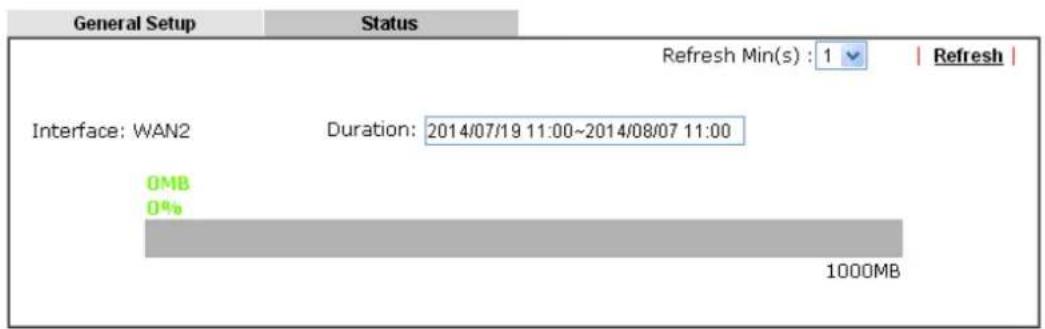
text_image
General Setup Status Refresh Min(s) : 1 | Refresh | Interface: WAN2 Duration: 2014/07/19 11:00~2014/08/07 11:00 OMB 0% 1000MBIf the WAN budget is exhausted, a lock will be displayed on the page if Shutdown WAN interface is selected. Which means no data transmission will be carried out. Moreover, the system will send out a warning message to the administrator if Mail Alert is selected. Or, the system will send out SMS message to the administrator if SMS message is selected.
WAN >> WAN Budget
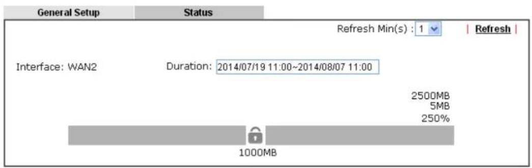
text_image
General Setup Status Refresh Min(s) : 1 | Refresh | Interface: WAN2 Duration: 2014/07/19 11:00~2014/08/07 11:00 2500MB 5MB 250% 1000MBApplication Notes
A-1 How to set up Multi-VLAN for triple play deployment?
By adding VLAN tags to differentiate the traffic, the service provider is able to deliver video, voice, and data to the subscribers over a single connection, which is also known as the triple play service. This document is going to demonstrate how to configure the Multi-PVC feature for triple play deployment. There are two types of setup, one is doing port-based bridge that will connect the media, such as the set-top box (STB), directly to the service provider via a specific LAN port; the other is opening a virtual WAN interface and doing NAT for the application.
Bridge the Virtual WAN to a LAN port
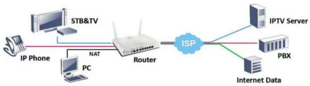
flowchart
graph LR
    A["IP Phone"] -->|STB&TV| B["Router"]
    C["PC"] -->|NAT| B
    B --> D["ISP"]
    D --> E["IPTV Server"]
    D --> F["Internet Data"]
    E --> G["PBX"]
- Go to WAN >> Multi-VLAN, click on a channel to configure.
WAN >> Multi-VLAN
| Channel | Enable | WAN Type | VLAN Tag | Port-based Bridge |
| 1 | ☑ | Ethernet(WAN1) | None | |
| 2 | ☑ | Ethernet(WAN2) | None | |
| 5. WAN5 | ☐ | Ethernet(WAN1) | None | Enable ☐P1 ☐P2 ☐P3 ☐P4 |
| 6. WAN6 | ☐ | Ethernet(WAN1) | None | Enable ☐P1 ☐P2 ☐P3 ☐P4 |
| 7. WAN7 | ☐ | Ethernet(WAN1) | None | Enable ☐P1 ☐P2 ☐P3 ☐P4 |
| 8. | ☐ | Ethernet(WAN1) | None | Enable ☐P1 ☐P2 ☐P3 ☐P4 |
| 9. | ☐ | Ethernet(WAN1) | None | Enable ☐P1 ☐P2 ☐P3 ☐P4 |
| 10. | ☐ | Ethernet(WAN1) | None | Enable ☐P1 ☐P2 ☐P3 ☐P4 |
Note:
Channel 3 and channel 4 are reserved for USB WAN.

- Configure the channel as follows,
WAN >> Multi-VLAN >> Channel 8
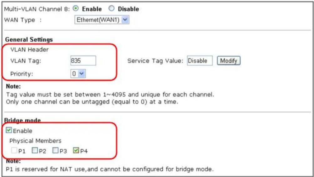
text_image
Multi-VLAN Channel 8: Enable Disable WAN Type : Ethernet(WAN1) General Settings VLAN Header VLAN Tag: 835 Service Tag Value: Disable Modify Priority: 0 Note: Tag value must be set between 1~4095 and unique for each channel. Only one channel can be untagged (equal to 0) at a time. Bridge mode Enable Physical Members P1 P2 P3 P4 Note: P1 is reserved for NAT use, and cannot be configured for bridge mode.
(a) enable this channel
(b) set WAN Type to the WAN interface that the service provider is on.
(c) enter the VLAN Tag and Priority as the service provider requires.
(d) check Enable for Bridge Mode, and select the physical port member to which you're going to connect the STB.
- Click OK to save the configuration, the configuration will be displayed on the main page. And now you may connect the STB to the Bridged port to use the IPTV service.
WAN >> Multi-VLAN
Multi-VLAN
| General | ||||
| Channel | Enable | WAN Type | VLAN Tag | Port-based Bridge |
| 1 | Yes | Ethernet(WAN1) | None | |
| 2 | Yes | Fiber(WAN2) | None | |
| 5. WAN5 | No | Ethernet(WAN1) | None | Enable P1 P2 P3 P4 |
| 6. WAN6 | No | Ethernet(WAN1) | None | Enable P1 P2 P3 P4 |
| 7. WAN7 | No | Ethernet(WAN1) | None | Enable P1 P2 P3 P4 |
| 8. | No | Ethernet(WAN1) | None | Enable P1 P2 P3 P4 |
| 9. | No | Ethernet(WAN1) | None | Enable P1 P2 P3 P4 |
| 10. | No | Ethernet(WAN1) | None | Enable P1 P2 P3 P4 |
Note:
Channel 3 and channel 4 are reserved for USB WAN.

Open a Virtual WAN Interface
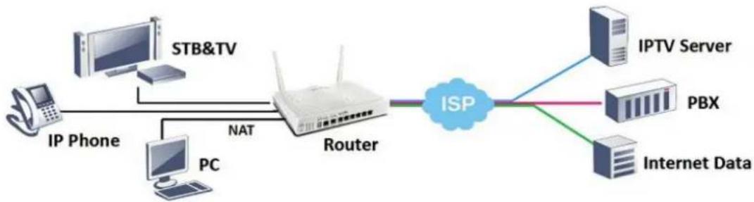
flowchart
graph LR
    A["IP Phone"] --> B["Router"]
    C["STB&TV"] --> B
    D["PC"] --> B
    B --> E["ISP"]
    E --> F["IPTV Server"]
    E --> G["PBX"]
    E --> H["Internet Data"]
    style B fill:#f9f,stroke:#333
    style E fill:#ccf,stroke:#333
- Go to WAN >> Multi-VLAN, click on channel 5, 6 or 7 to configure.
WAN >> Multi-VLAN
Multi-VLAN
| General | ||||
| Channel | Enable | WAN Type | VLAN Tag | Port-based Bridge |
| 1 | Ethernet(WAN1) | None | ||
| 2 | Ethernet(WAN2) | None | ||
| 5. WAN5 | Ethernet(WAN1) | None | Enable P1 P2 P3 P4 | |
| 6. WAN6 | Ethernet(WAN1) | None | Enable P1 P2 P3 P4 | |
| 7. WAN7 | Ethernet(WAN1) | None | Enable P1 P2 P3 P4 | |
| 8. | Ethernet(WAN1) | None | Enable P1 P2 P3 P4 | |
| 9. | Ethernet(WAN1) | None | Enable P1 P2 P3 P4 | |
| 10. | Ethernet(WAN1) | None | Enable P1 P2 P3 P4 | |
Note:
Channel 3 and channel 4 are reserved for USB WAN.

- Configure the channel as follows,
WAN >> Multi-VLAN >> Channel 5
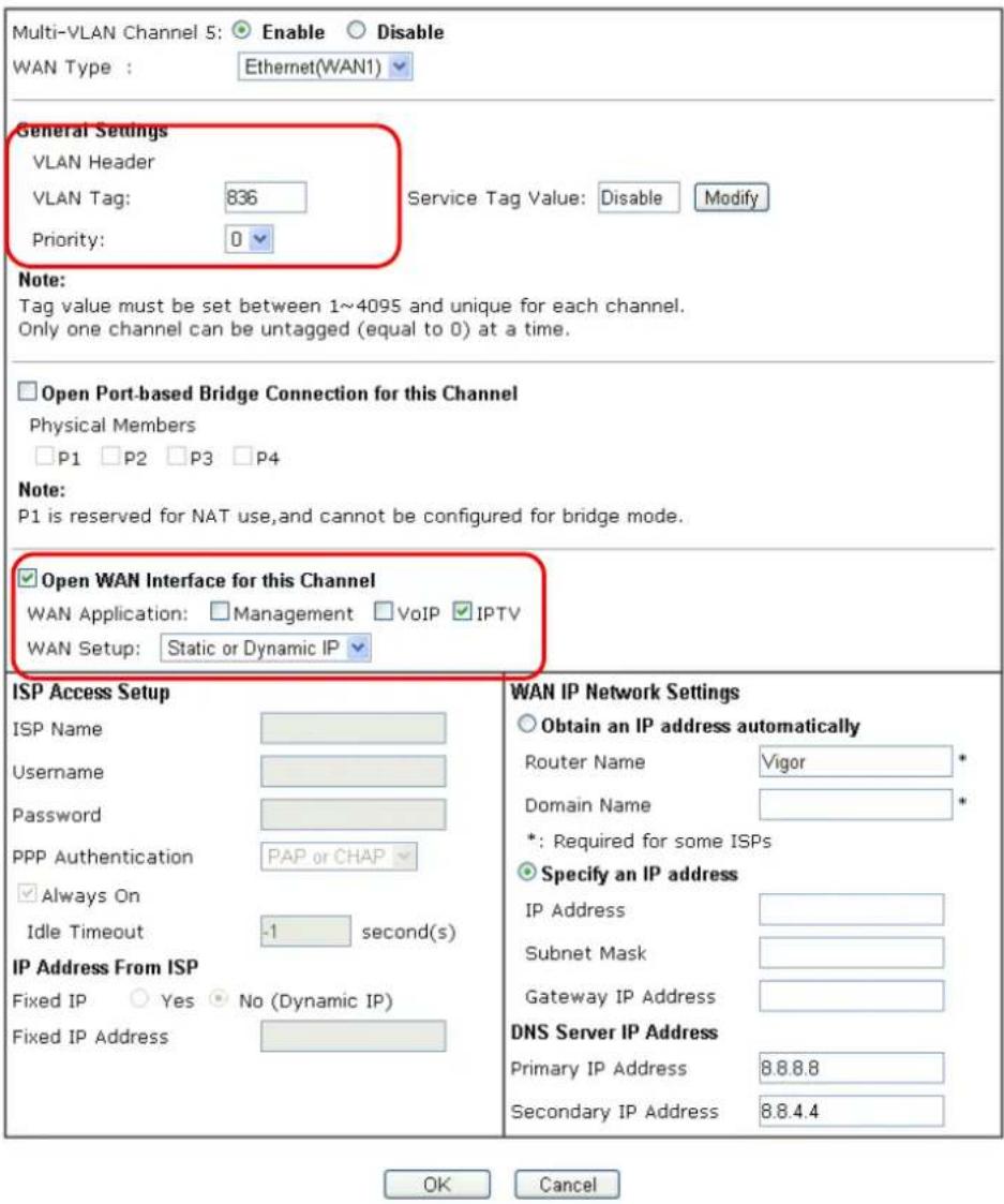
text_image
Multi-VLAN Channel 5: Enable Disable WAN Type : Ethernet(WAN1) General Settings VLAN Header VLAN Tag: 836 Service Tag Value: Disable Modify Priority: 0 Note: Tag value must be set between 1~4095 and unique for each channel. Only one channel can be untagged (equal to 0) at a time. Open Port-based Bridge Connection for this Channel Physical Members P1 P2 P3 P4 Note: P1 is reserved for NAT use,and cannot be configured for bridge mode. Open WAN Interface for this Channel WAN Application: Management VoIP IPTV WAN Setup: Static or Dynamic IP ISP Access Setup ISP Name Username Password PPP Authentication PAP or CHAP Always On Idle Timeout -1 second(s) IP Address From ISP Fixed IP Yes No (Dynamic IP) Fixed IP Address WAN IP Network Settings Obtain an IP address automatically Router Name Vigor * Domain Name * *: Required for some ISPs Specify an IP address IP Address Subnet Mask Gateway IP Address DNS Server IP Address Primary IP Address 8.8.8.8 Secondary IP Address 8.8.4.4 OK Cancel(a) enable this channel.
(b) set WAN Type to the WAN interface that the service provider is on.
(c) enter the VLAN Tag and Priority as the service provider requires.
(d) enable "Open WAN Interface for this Channel", and select the kind of Application will be used on this channel. (Note: this option is only available on channel 5-7)
(e) set up the Internet Access type as the ISP requires.
- Click OK to save the profile and reboot the router to apply the settings. After the router restart, go to Online Status >> Virtual WAN to make sure the WAN interface is up and has obtained an IP address.
Online Status
Virtual WAN
System Uptime: 0day 0:1:23
| WAN 5 Status | >> Release | ||||
| Enable | Line | Name | Mode | Up Time | Application |
| Yes | Ethernet(WAN2) | DHCP Client | 0:00:10 | IPTV | |
| IP | GW IP | TX Packets | TX Rate(Bps) | RX Packets | RX Rate(Bps) |
| 10.15.15.20 | 10.15.15.1 | 0 | 0 | 2 | 27 |
| WAN 6 Status | |||||
| Enable | Line | Name | Mode | Up Time | Application |
| No | ADSL | --- | 00:00:00 | Management | |
| IP | GW IP | TX Packets | TX Rate(Bps) | RX Packets | RX Rate(Bps) |
| --- | --- | 0 | 0 | 0 | 0 |
| WAN 7 Status | |||||
| Enable | Line | Name | Mode | Up Time | Application |
| No | ADSL | --- | 00:00:00 | Management | |
| IP | GW IP | TX Packets | TX Rate(Bps) | RX Packets | RX Rate(Bps) |
| --- | --- | 0 | 0 | 0 | 0 |
- Now, you may use the virtual WAN interface for applications such as IGMP Proxy, this can be done by selecting the WAN interface as "PVC/ VLAN".
Applications >> IGMP
General setting
Working groups
IGMP Proxy
IGMP Proxy acts as a multicast proxy for hosts on the LAN side. Enable IGMP proxy to access any multicast group. This function takes no effect when Bridge Mode is enabled.
Interface
IGMP version
General Query Interval
Add PPP header
(Encapsulate IGMP in PPPoE)




IGMP Snooping
Enable: Forwards multicast traffic only to ports that are members of that group. Disable: Treats multicast traffic the same as broadcast traffic.
IGMP Fast Leave
The router stops forwarding multicast traffic to a LAN port as soon as it receives a leave message from that port. Each LAN port should have no more than one IGMP host connected.
OK
Cancel
A-2 Load Balancing and Failover for multi-WAN Vigor Routers
Network Administrator may set up multiple Internet connection to share the traffic load, or add a redundant Internet connection to the router and gives a higher reliability to the network connection.
Load Balancing
By default, all the active WAN interfaces will join the load balance pool when they are connected, and the outgoing traffic will take either of the active WAN as their path, therefore the traffic load is shared across the WAN interfaces. For newer models which support "Session-based" Load Balance, the router can also do WAN aggregation, which means the speed that LAN clients could experience will be the combination of all the active WAN's bandwidth (click here to learn more).
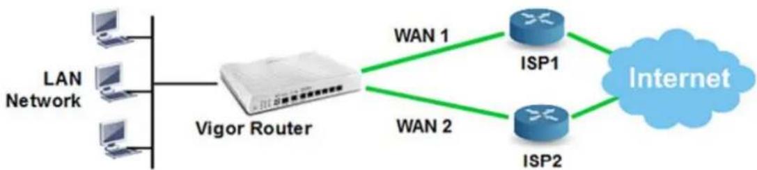
flowchart
graph LR
    A["LAN Network"] --> B["Vigor Router"]
    B --> C["WAN 1"]
    B --> D["WAN 2"]
    C --> E["ISP1"]
    D --> F["ISP2"]
    E --> G["Internet"]
    F --> G
To ensure that a WAN interface is in the load balance pool, go to WAN >> General Setup, click on the index, set Active Mode to "Always On" and make sure Load Balance is enabled.
WAN >> General Setup
WAN 1
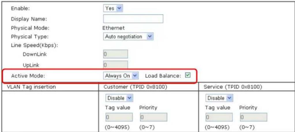
text_image
Enable: Yes Display Name: Physical Mode: Ethernet Physical Type: Auto negotiation Line Speed(Kbps): DownLink 0 UpLink 0 Active Mode: Always On Load Balance: VLAN Tag insertion Customer (TPID 0x8100) Service (TPID 0x8100) Disable Tag value Priority 0 0 (0~4095) (0~7) Tag value Priority 0 0 (0~4095) (0~7)Note:
- The line speed setting of WAN interface is available only when According to Line Speed is selected as the Load Balance Mode.
- Customer and service tag are used for different network environments. Customer tag is required for most ISPs while Service tag is required when ISP needs QinQ packets.
OK Cancel
The default load balance weight is determined based on the peak bandwidth detected on each WAN interface, but Network Administrator may also use "According to Line Speed Mode" to define the maximum bandwidth which will affect the weight (click here to learn more). Furthermore, Network Administrator would like to specify an outgoing path for some traffic while there are multiple WAN interfaces, Route Policy will be the solution, click here for an instruction of how to designate a WAN interface for LAN clients by Route Policy.
Failover
When configured in Failover mode, the WAN interface will only be active when the primary WAN disconnects, and will be down again when the primary WAN resume its service.
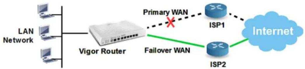
flowchart
graph LR
    A["LAN Network"] --> B["Vigor Router"]
    B --> C["Primary WAN"]
    C --> D["ISP1"]
    C --> E["ISP2"]
    D --> F["Internet"]
    E --> F
    B --> G["Failover WAN"]
To configure a WAN interface in Failover mode, go to WAN >> General Setup, click on the index which you would like to configure to Failover Mode, set Active Mode to "Failover", and for Active When, choose the conditions about when should this interface be activated.
WAN >> General Setup
WAN 2
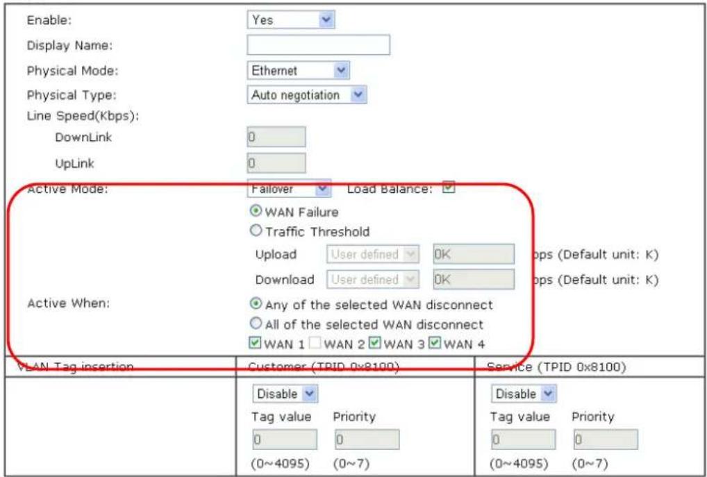
text_image
Enable: Yes Display Name: Physical Mode: Ethernet Physical Type: Auto negotiation Line Speed(Kbps): DownLink 0 UpLink 0 Active Mode: Failover Load Balance: WAN Failure Traffic Threshold Upload User defined OK Download User defined OK Active When: Any of the selected WAN disconnect All of the selected WAN disconnect WAN 1 WAN 2 WAN 3 WAN 4 VLAN Tag insertion Customer (TPID 0x8100) Service (TPID 0x8100) Disable Tag value Priority 0 0 (0~4095) (0~7) Disable Tag value Priority 0 0 (0~4095) (0~7)Note:
- The line speed setting of WAN interface is available only when According to Line Speed is selected as the Load Balance Mode.
- Customer and service tag are used for different network environments. Customer tag is required for most ISPs while Service tag is required when ISP needs QinQ packets.

Info
Router determines if a WAN is disconnected or not according to "WAN Connection Detection" settings in WAN >> Internet Access.
II-2 LAN
Local Area Network (LAN) is a group of subnets regulated and ruled by router. The design of network structure is related to what type of public IP addresses coming from your ISP.
The most generic function of Vigor router is NAT. It creates a private subnet of your own. As mentioned previously, the router will talk to other public hosts on the Internet by using public IP address and talking to local hosts by using its private IP address. What NAT does is to translate the packets from public IP address to private IP address to forward the right packets to the right host and vice versa. Besides, Vigor router has a built-in DHCP server that assigns private IP address to each local host. See the following diagram for a briefly understanding.
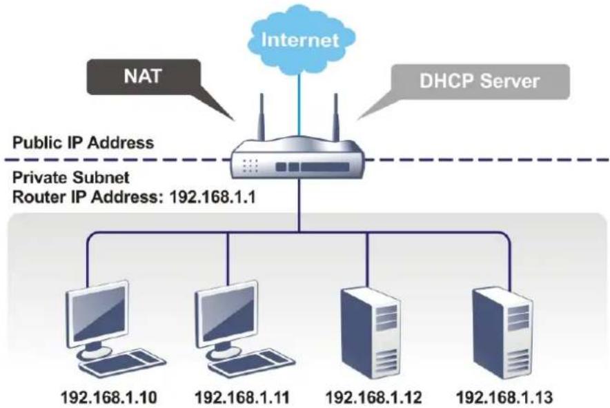
flowchart
graph TD
    A["Internet"] --> B["NAT"]
    A --> C["DHCP Server"]
    B --> D["Public IP Address"]
    C --> E["Private Subnet Router IP Address: 192.168.1.1"]
    D --> F["Computer 192.168.1.10"]
    D --> G["Computer 192.168.1.11"]
    D --> H["Computer 192.168.1.12"]
    D --> I["Computer 192.168.1.13"]
In some special case, you may have a public IP subnet from your ISP such as 220.135.240.0/24. This means that you can set up a public subnet or call second subnet that each host is equipped with a public IP address. As a part of the public subnet, the Vigor router will serve for IP routing to help hosts in the public subnet to communicate with other public hosts or servers outside. Therefore, the router should be set as the gateway for public hosts.
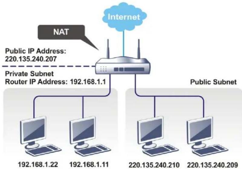
flowchart
graph TD
    A["Internet"] --> B["NAT"]
    B --> C["Router"]
    C --> D["Public Subnet"]
    C --> E["192.168.1.22"]
    C --> F["192.168.1.11"]
    C --> G["220.135.240.210"]
    C --> H["220.135.240.209"]
    I["Public IP Address: 220.135.240.207"] -.-> C
What is Routing Information Protocol (RIP)
Vigor router will exchange routing information with neighboring routers using the RIP to accomplish IP routing. This allows users to change the information of the router such as IP address and the routers will automatically inform for each other.
What is Static Route
When you have several subnets in your LAN, sometimes a more effective and quicker way for connection is the Static routes function rather than other method. You may simply set rules to forward data from one specified subnet to another specified subnet without the presence of RIP.
What are Virtual LANs and Rate Control
You can group local hosts by physical ports and create up to 8 virtual LANs. To manage the communication between different groups, please set up rules in Virtual LAN (VLAN) function and the rate of each.
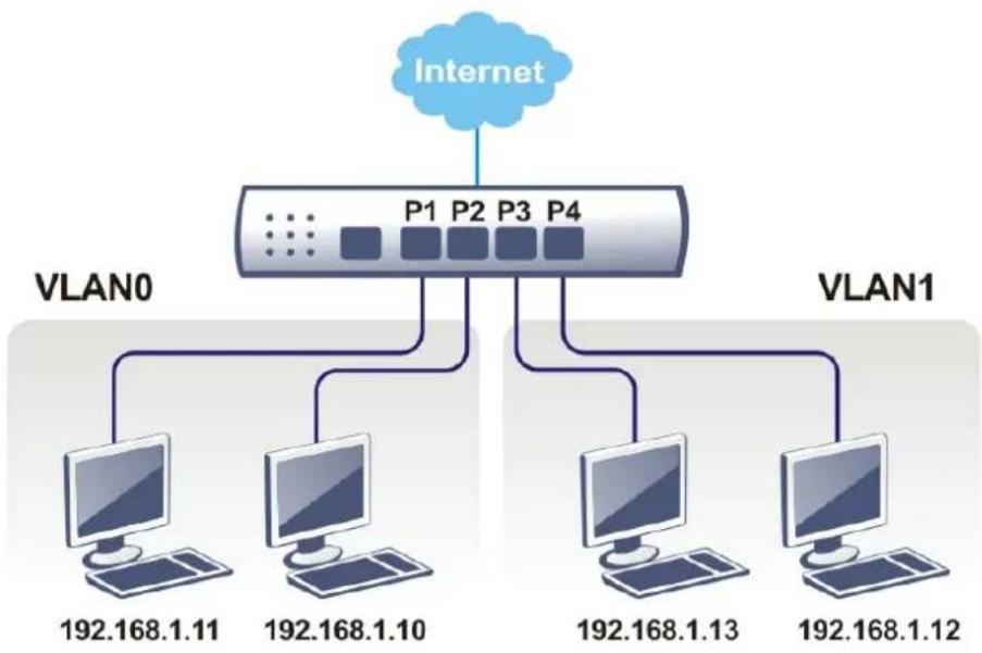
flowchart
graph TD
    A["Internet"] --> B["VLAN0"]
    A --> C["VLAN1"]
    B --> D["192.168.1.11"]
    B --> E["192.168.1.10"]
    C --> F["192.168.1.13"]
    C --> G["192.168.1.12"]
Web User Interface
A LAN comprises a collection of LAN clients, which are networked devices on your premises. A LAN client can be a computer, a printer, a Voice-over-IP (VoIP) phone, a mobile phone, a gaming console, an Internet Protocol Television (IPTV), etc, and can have either a wired (using Ethernet cabling) or wireless (using Wi-Fi) network connection.
LAN clients within the same LAN are normally able to communicate with one another directly, as they are peers to one another, unless measures, such as firewalls or VLANs, have been put in place to restrict such access. Nowadays the most common LAN firewalls are implemented on the LAN client itself. For example, Microsoft Windows since Windows XP and Apple OS X have built-in firewalls that can be configured to restrict traffic coming in and going out of the computer. VLANs, on the other hand, are usually set up using network switches or routers, such as the Vigor2926.
To communicate with the hosts outside of the LAN, LAN clients have to go through a network gateway, which in most cases is a router (such as the Vigor 2926) that sits between the LAN and the ISP network, which is the WAN. The router acts as a director to ensure traffic between the LAN and the WAN reach their intended destinations.
LAN
General Setup
VLAN
Bind IP to MAC
LAN Port Mirror
Wired 802.1X
II-2-1 General Setup
This page provides you the general settings for LAN. Click LAN to open the LAN settings page and choose General Setup.
There are four subnets provided by the router which allow users to divide groups into different subnets (LAN1 - LAN5). In addition, different subnets can link for each other by configuring Inter-LAN Routing. At present, LAN1 setting is fixed with NAT mode only. LAN2 - LAN8 can be operated under NAT or Route mode. IP Routed Subnet can be operated under Route mode.
General Setup
| Index | Enable | DHCP | IP Address | ||
| LAN 1 | V | V | 192.168.1.1 | Details Page | IPv6 |
| LAN 2 | 192.168.2.1 | Details Page | IPv6 | ||
| LAN 3 | 192.168.3.1 | Details Page | IPv6 | ||
| LAN 4 | 192.168.4.1 | Details Page | IPv6 | ||
| LAN 5 | 192.168.5.1 | Details Page | IPv6 | ||
| LAN 6 | 192.168.6.1 | Details Page | IPv6 | ||
| LAN 7 | 192.168.7.1 | Details Page | IPv6 | ||
| LAN 8 | 192.168.8.1 | Details Page | IPv6 | ||
| DMZ Port | 192.168.254.1 | Details Page | IPv6 | ||
| IP Routed Subnet | 192.168.0.1 | Details Page |
DHCP Server Option
Note:
Please enable LAN 2 - 8 on LAN >> VLAN page before configure them.
Enable DMZ port will make the LAN Port 4 neglect the setting on VLAN page, LAN Port 4 will become the DMZ Port.
☐ Force router to use "DNS server IP address" settings specified in LAN1
Inter-LAN Routing
Available settings are explained as follows:
| Item | Description |
| General Setup | Allow to configure settings for each subnet respectively. Index - Display all of the LAN items. Status- Basically, LAN1 status is enabled in default. LAN2 -LAN5 and IP Routed Subnet can be observed by checking the box of Status. DHCP- LAN1 is configured with DHCP in default. If required, please check the DHCP box for each LAN. IP Address - Display the IP address for each LAN item. Such information is set in default and you can not modify it. Details Page - Click it to access into the setting page. Each LAN will have different LAN configuration page. Each LAN must be configured in different subnet. IPv6 - Click it to access into the settings page of IPv6. |
| DHCP Server Option DHCP packets can be processed by adding option number and data information when such function is enabled. | |
| For detailed information, refer to later section. | |
| Force router to use “DNS server IP address .....” | Force Vigor router to use DNS servers configured in LAN1/ LAN2/ LAN3/ LAN4/ LAN5/ LAN6/ LAN7/ LAN8/ DMZ Port instead of DNS servers given by the Internet Access server (PPPoE, PPTP, L2TP or DHCP server). |
| Inter-LAN Routing Check the box to link two or more different subnets (LAN and LAN).Inter-LAN Routing allows different LAN subnets to be interconnected or isolated.It is only available when the VLAN functionality is enabled.Refer to section II-2-2 VLAN on how to set up VLANs.In the Inter-LAN Routing matrix, a selected checkbox means that the 2 intersecting LANs can communicate with each other. | |
When you finish the configuration, please click OK to save.

Info
To configure a subnet, select its Detials Page button to bring up the LAN Details Page.
II-2-1-1 Details Page for LAN1 – Ethernet TCP/IP and DHCP Setup
There are two configuration pages for LAN1, Ethernet TCP/IP and DHCP Setup (based on IPv4) and IPv6 Setup. Click the tab for each type and refer to the following explanations for detailed information.
LAN >> General Setup
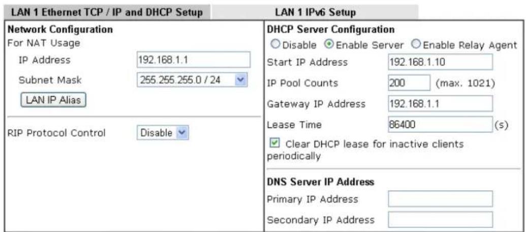
text_image
LAN 1 Ethernet TCP / IP and DHCP Setup LAN 1 IPv6 Setup Network Configuration For NAT Usage IP Address 192.168.1.1 Subnet Mask 255.255.255.0 / 24 LAN IP Alias RIP Protocol Control Disable DHCP Server Configuration Disable Enable Server Enable Relay Agent Start IP Address 192.168.1.10 IP Pool Counts 200 (max. 1021) Gateway IP Address 192.168.1.1 Lease Time 86400 (s) Clear DHCP lease for inactive clients periodically DNS Server IP Address Primary IP Address Secondary IP AddressNote: Change IP Address or Subnet Mask in Network Configuration will also change HA LAN1 Virtual IP to the same domain IP.
OK
Available settings are explained as follows:
| Item | Description |
| Network Configuration For | NAT Usage,IP Address - This is the IP address of the router. (Default: 192.168.1.1).Subnet Mask - The subnet mask, together with the IP Address field, indicates the maximum number of clients allowed on the subnet. (Default: 255.255.255.0/ 24).LAN IP Alias -Such feature allows specifying multiple gateways (under a switch) with different WAN interfaces for accessing the Internet via the Vigor router.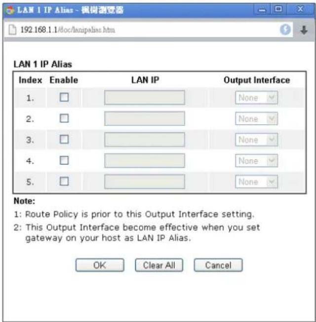 RIP Protocol Control,Enable - When Enabled, the router will attempt to exchange routing information with neighbouring routers using the Routing Information Protocol. RIP Protocol Control,Enable - When Enabled, the router will attempt to exchange routing information with neighbouring routers using the Routing Information Protocol. |
| DHCP ServerConfiguration | DHCP stands for Dynamic Host Configuration Protocol. The router by factory default acts a DHCP server for your network so it automatically dispatches related IP settings to any local user configured as a DHCP client. It is highly recommended that you leave the router enabled as a DHCP server if you do not have a DHCP server for your network.If you want to use another DHCP server in the network other than the Vigor Router's, you can let Relay Agent help you to redirect the DHCP request to the specified location.Disable Server - Let you manually assign IP address to every host in the LAN.Enable Server - Let the router assign IP address to every host in the LAN.Start IP Address - The beginning LAN IP address that is given out to LAN DHCP clients.IP Pool Counts - The maximum number of IP addresses to be handed out by DHCP. The default value is 200. Valid range is between 1 and 1021. The actual number of IP addresses available for assignment is the IP Pool Counts, or 1021 minus the last octet of the Start IP Address, whichever is smaller.Gateway IP Address - The IP address of the gateway, which is the host on the LAN that relays all traffic coming into and going out of the LAN. The gateway is normally the router, and therefore the Gateway IP Address should be identical to the IP Address in theNetwork Configuration section above.● Lease Time - The maximum duration DHCP-issued IP addresses can be used before they have to be renewed.● Clear DHCP lease for inactive clients periodically - If selected, the router sends ARP requests recycles IP addresses previously assigned to inactive DHCP clients to prevent exhaustion of the IP address pool.Note: When Clear DHCP lease for inactive clients periodically is enabled, router will do the following:■ Check activities of DHCP clients by ARP requests every minute when the available DHCP IP addresses are less than 30■ Clear DHCP lease when the client is not responding ARP replies.Enable Relay Agent - When selected, all DHCP requests are forwarded to a DHCP server outside of the LAN subnet, and whose address is specified in the DHCP Server IP Address field.● DHCP Server IP Address - It is available when Enable Relay Agent is checked. Set the IP address of the DHCP server you are going to use so the Relay Agent can help to forward the DHCP request to the DHCP server. |
| DNS Server IP Address DNS | stands for Domain Name System. Every Internet host must have a unique IP address, also they may have a human-friendly, easy to remember name such as www.yahoo.com. The DNS server converts the user-friendly name into its equivalent IP address.Primary IP Address -You must specify a DNS server IP address here because your ISP should provide you with usually more than one DNS Server.Secondary IP Address - You can specify secondary DNS server IP address here because your ISP often provides you more than one DNS Server.The default DNS Server IP address can be found via Online Status:Online Status If both the Primary IP and Secondary IP Address fields are left empty, the router will assign DNS servers obtained from WAN interface to local users as a DNS proxy server and maintain a DNS cache. If there is no DNS servers available, router will use its own IP address instead.If the IP address of a domain name is already in the DNS cache, the router will resolve the domain name immediately. Otherwise, the router forwards the DNS query packet to the external DNS server by establishing a WAN (e.g. DSL/ Cable) connection. If both the Primary IP and Secondary IP Address fields are left empty, the router will assign DNS servers obtained from WAN interface to local users as a DNS proxy server and maintain a DNS cache. If there is no DNS servers available, router will use its own IP address instead.If the IP address of a domain name is already in the DNS cache, the router will resolve the domain name immediately. Otherwise, the router forwards the DNS query packet to the external DNS server by establishing a WAN (e.g. DSL/ Cable) connection. |
When you finish the configuration, please click OK to save and exit this page.
Private IP addresses can be assigned automatically to LAN clients using Dynamic Host Configuration Protocol (DHCP), or manually assigned. The DHCP server can either be the router (the most common case), or a separate server, that hands out IP addresses to DHCP clients.
Alternatively, static IP addresses can be manually configured on LAN clients as part of their network settings. No matter how IP addresses are configured, it is important that no two devices get the same IP address. If both DHCP and static assignment are used on a network, it is important to exclude the static IP addresses from the DHCP IP pool. For example, if your LAN uses the 192.168.1.x subnet and you have 20 DHCP clients and 20 static IP clients, you could configure 192.168.1.10 as the Start IP Address, 50 as the IP Pool Counts (enough for the current number of DHCP clients, plus room for future expansion), and use addresses greater than 192.168.1.100 for static assignment.
II-2-1-2 Details Page for LAN2 \~ LAN8 and DMZ
LAN >> General Setup
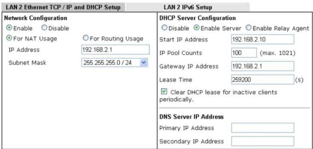
text_image
LAN 2 Ethernet TCP / IP and DHCP Setup LAN 2 IPv6 Setup Network Configuration Enable Disable For NAT Usage For Routing Usage IP Address 192.168.2.1 Subnet Mask 255.255.255.0 / 24 DHCP Server Configuration Disable Enable Server Enable Relay Agent Start IP Address 192.168.2.10 IP Pool Counts 100 (max. 1021) Gateway IP Address 192.168.2.1 Lease Time 259200 (s) Clear DHCP lease for inactive clients periodically. DNS Server IP Address Primary IP Address Secondary IP AddressNote: Change IP Address or Subnet Mask in Network Configuration will also change HA LAN2 Virtual IP to the same domain IP.
OK
Available settings are explained as follows:
| Item | Description |
| Network Configuration | Enable/Disable - Click Enable to enable such configuration; click Disable to disable such configuration.For NAT Usage - Click this radio button to invoke NAT function.For Routing Usage - Click this radio button to invoke this function.IP Address - This is the IP address of the router. (Default: 192.168.1.1).Subnet Mask - The subnet mask, together with the IP Address field, indicates the maximum number of clients allowed on the subnet. (Default: 255.255.255.0/ 24). |
| DHCP Server Configuration | Disable Server - Let you manually assign IP address to every host in the LAN.Enable Server - Let the router assign IP address to every host in the LAN.Start IP Address - The beginning LAN IP address that is given out to LAN DHCP clients.IP Pool Counts - The maximum number of IP addresses to be handed out by DHCP. The default value is 100. Valid range is between 1 and 1021. The actual number of IP addresses available for assignment is the IP Pool Counts, or 1021 minus the last octet of the Start IP Address, whichever is smaller.Gateway IP Address - The IP address of the gateway, which is the host on the LAN that relays all traffic coming into and going out of the LAN. The gateway is normally the router, and therefore the Gateway IP Address should be identical to the IP Address in theNetwork Configuration section above.● Lease Time - The maximum duration DHCP-issued IP addresses can be used before they have to be renewed.● Clear DHCP lease for inactive clients periodically - If selected, the router sends ARP requests recycles IP addresses previously assigned to inactive DHCP clients to prevent exhaustion of the IP address pool.Note: When Clear DHCP lease for inactive clients periodically is enabled, router will do the following:■ Check activities of DHCP clients by ARP requests every minute when the available DHCP IP addresses are less than 30■ Clear DHCP lease when the client is not responding ARP replies.Enable Relay Agent - When selected, all DHCP requests are forwarded to a DHCP server outside of the LAN subnet, and whose address is specified in the DHCP Server IP Address field.● DHCP Server IP Address - It is available when Enable Relay Agent is checked. Set the IP address of the DHCP server you are going to use so the Relay Agent can help to forward the DHCP request to the DHCP server. |
| DNS Server IP Address DNS | stands for Domain Name System. Every Internet host must have a unique IP address, also they may have a human-friendly, easy to remember name such as www.yahoo.com. The DNS server converts the user-friendly name into its equivalent IP address.Primary IP Address -You must specify a DNS server IP address here because your ISP should provide you with usually more than one DNS Server.Secondary IP Address - You can specify secondary DNS server IP address here because your ISP often provides you more than one DNS Server.The default DNS Server IP address can be found via Online Status:Online Status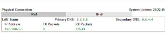 If both the Primary IP and Secondary IP Address fields are left empty, the router will assign its own IP address to local users as a DNS proxy server and maintain a DNS cache.If the IP address of a domain name is already in the DNS cache, the router will resolve the domain name immediately. Otherwise, the router forwards the DNS query packet to the external DNS server by establishing a WAN (e.g. DSL/ Cable) connection. If both the Primary IP and Secondary IP Address fields are left empty, the router will assign its own IP address to local users as a DNS proxy server and maintain a DNS cache.If the IP address of a domain name is already in the DNS cache, the router will resolve the domain name immediately. Otherwise, the router forwards the DNS query packet to the external DNS server by establishing a WAN (e.g. DSL/ Cable) connection. |
When you finish the configuration, please click OK to save and exit this page.
II-2-1-3 Details Page for IP Routed Subnet
LAN >> General Setup
TCP/IP and DHCP Setup for IP Routed Subnet
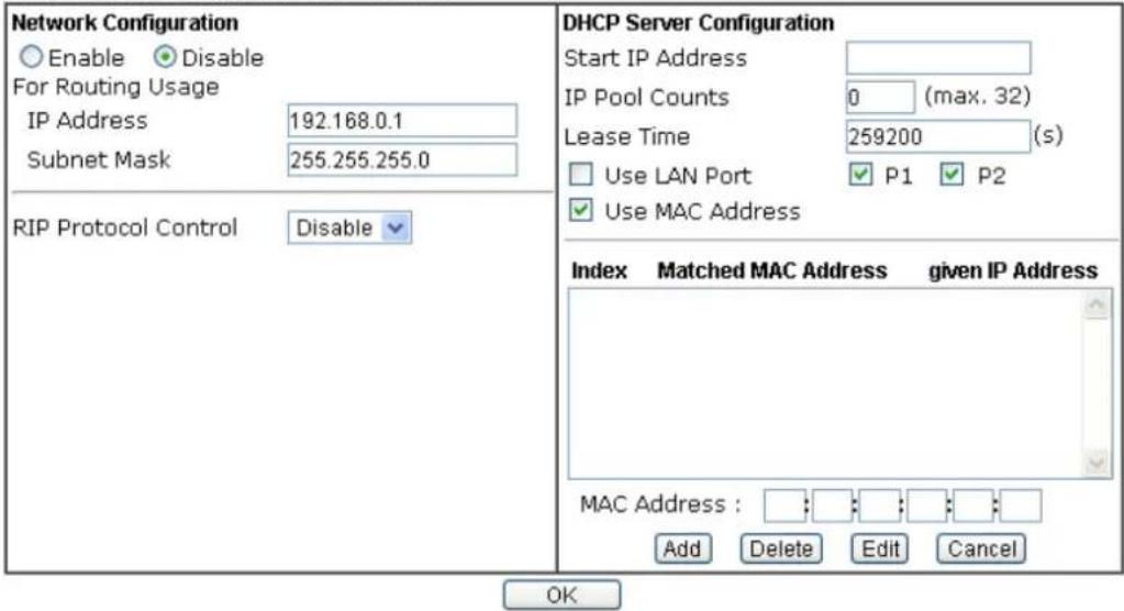
text_image
Network Configuration Enable Disable For Routing Usage IP Address 192.168.0.1 Subnet Mask 255.255.255.0 RIP Protocol Control Disable DHCP Server Configuration Start IP Address IP Pool Counts 0 (max. 32) Lease Time 259200 (s) Use LAN Port P1 P2 Use MAC Address Index Matched MAC Address given IP Address MAC Address : Add Delete Edit Cancel OKAvailable settings are explained as follows:
| Item | Description |
| Network Configuration | Enable/Disable - Click Enable to enable such configuration; click Disable to disable such configuration.For Routing Usage,IP Address - This is the IP address of the router. (Default: 192.168.1.1).Subnet Mask - The subnet mask, together with the IP Address field, indicates the maximum number of clients allowed on the subnet. (Default: 255.255.255.0/ 24).RIP Protocol Control,Enable - When Enabled, the router will attempt to exchange routing information with neighbouring routers using the Routing Information Protocol. |
| DHCP Server Configuration | DHCP stands for Dynamic Host Configuration Protocol. The router by factory default acts a DHCP server for your network so it automatically dispatch related IP settings to any local user configured as a DHCP client. It is highly recommended that you leave the router enabled as a DHCP server if you do not have a DHCP server for your network.If you want to use another DHCP server in the network other than the Vigor Router's, you can let Relay Agent help you to redirect the DHCP request to the specified location.Start IP Address - Enter a value of the IP address pool for the DHCP server to start with when issuing IP addresses. If the 1st IP address of your router is 192.168.1.1, the starting IP address must be 192.168.1.2 or greater, but smaller than 192.168.1.254.IP Pool Counts - Enter the maximum number of PCs that you want the DHCP server to assign IP addresses to. The default is50 and the maximum is 253.Lease Time- Enter the time to determine how long the IP address assigned by DHCP server can be used.Use LAN Port- Specify an IP for IP Route Subnet. If it is enabled, DHCP server will assign IP address automatically for the clients coming from P1 and/ or P2. Please check the box of P1 and P2.Use MAC Address- Check such box to specify MAC address.MAC Address:Enter the MAC Address of the host one by one and clickAddto create a list of hosts which can be assigned, deleted or edited from above pool. Set a list of MAC Address for 2^nd DHCP server will help router to assign the correct IP address of the correct subnet to the correct host. So those hosts in 2^nd subnet won’t get an IP address belonging to 1^st subnet.Add- Enter the MAC address in the boxes and click this button to add.Delete- Click it to delete the selected MAC address.Edit- Click it to edit the selected MAC address.Cancel- Click it to cancel the job of adding, deleting and editing. |
When you finish the configuration, please click OK to save and exit this page.
II-2-1-4 Details Page for LAN IPv6 Setup
There are two configuration pages for LAN1/ LAN2/ LAN3/ LAN4/ LAN5/ LAN6/ DMZ Port, Ethernet TCP/ IP and DHCP Setup (based on IPv4) and IPv6 Setup. Click the tab for each type and refer to the following explanations for detailed information. Below shows the settings page for IPv6.
LAN >> General Setup
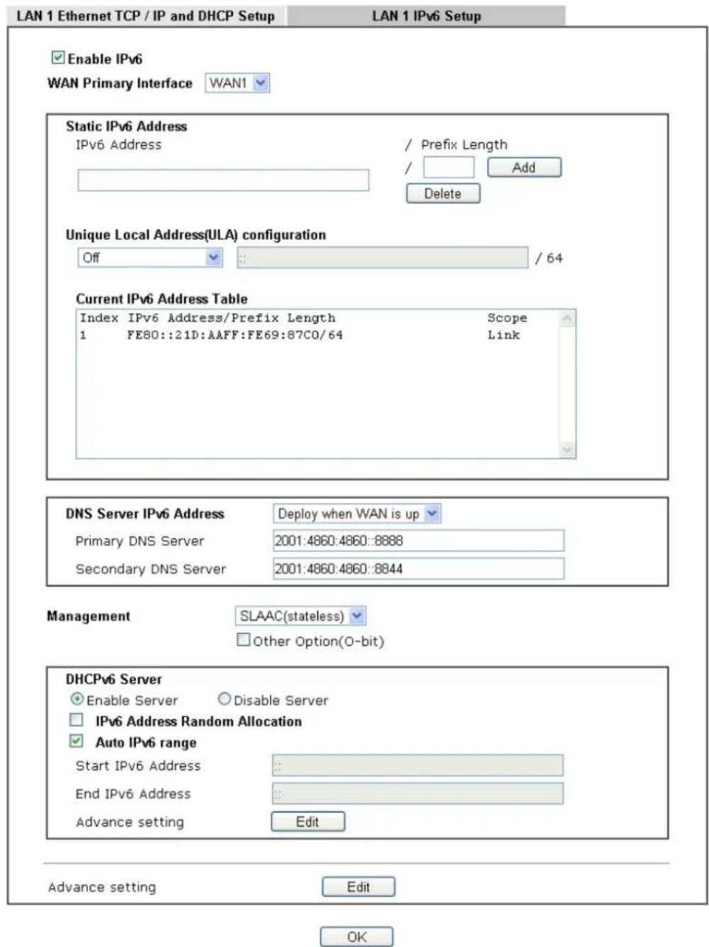
text_image
LAN 1 Ethernet TCP / IP and DHCP Setup LAN 1 IPv6 Setup Enable IPv6 WAN Primary Interface WAN1 Static IPv6 Address IPv6 Address / Prefix Length / Add Delete Unique Local Address(ULA) configuration Off / 64 Current IPv6 Address Table Index IPv6 Address/Prefix Length Scope 1 FE80::21D:AAFF:FE69:87C0/64 Link DNS Server IPv6 Address Deploy when WAN is up Primary DNS Server 2001:4860:4860::8888 Secondary DNS Server 2001:4860:4860::8844 Management SLAAC(stateless) Other Option(O-bit) DHCPv6 Server Enable Server Disable Server IPv6 Address Random Allocation Auto IPv6 range Start IPv6 Address End IPv6 Address Advance setting Edit Advance setting Edit OKIt provides 2 daemons for LAN side IPv6 address configuration. One is SLAAC(stateless) and the other is DHCPv6 (Stateful) server.
Available settings are explained as follows:
| Item | Description |
| Enable IPv6 Check the box to enable the configuration of LAN 1 IPv6 Setup. | |
| WAN Primary Interface | Use the drop down list to specify a WAN interface for IPv6. |
| Static IPv6 Address configuration | IPv6 Address -Type static IPv6 address for LANPrefix Length - Enter the fixed value for prefix length.Add - Click it to add a new entry.Delete - Click it to remove an existed entry. |
| Unique Local Address (ULA) configuration | Unique Local Addresses (ULAs) are private IPv6 addresses assigned to LAN clients.Off - ULA is disabled.Manually ULA Prefix - LAN clients will be assigned ULAs generated based on the prefix manually entered.Auto ULA Prefix - LAN clients will be assigned ULAs using an automatically-determined prefix.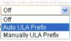 |
| Current IPv6 Address Table | Display current used IPv6 addresses. |
| DNS Server IPv6 Address Deploy when WAN is up - The RA (router advertisement) packets will be sent to LAN PC with DNS server information only when network connection by any one of WAN interfaces is up.Enable - The RA (router advertisement) packets will be sent to LAN PC with DNS server information no matter WAN connection is up or not.Primary DNS Sever - Enter the IPv6 address for Primary DNS server.Secondary DNS Server -Type another IPv6 address for DNS server if required.Disable - DNS server will not be used. | |
| Management | Configures the Managed Address Configuration flag (M-bit) in Route Advertisements.Off - No configuration information is sent using Route Advertisements.SLAAC(stateless) - M-bit is unset.DHCPv6(stateful) - M-bit is set, which indicates to LAN clients that they should acquire all IPv6 configuration information from a DHCPv6 server. The DHCPv6 server can either be the one built into the Vigor router, or a separate DHCPv6 server.SLAAC(stateless)SLAAC(stateless)DHCPv6(stateful)OffOther Option (O-bit) - Check this box to enable the O-bit for obtaining additional information (e.g., DNS) from DHCPv6.When selected, the Other Configuration flag is set, which indicates to LAN clients that IPv6 configuration information besides LAN IPv6 addresses is available from a DHCPv6 server.Setting the M-bit (see Management above) has the same effect as implicitly setting the O-bit, as DHCPv6 supplies all IPv6 configuration information, including what is indicated as available when the O-bit is set. |
| DHCPv6 Server Enable Server -Click it to enable DHCPv6 server. DHCPv6Server could assign IPv6 address to PC according to the | |
Start/ End IPv6 address configuration.
Disable Server -Click it to disable DHCPv6 server.
Auto IPv6 range - After check the box, Vigor router will assign the IPv6 range automatically.
Start IPv6 Address / End IPv6 Address -Enter the start and end address for IPv6 server.
Advance setting - Click the Edit button to configure advanced IPv6 settings for DHCPv6 server.
LAN >> General Setup
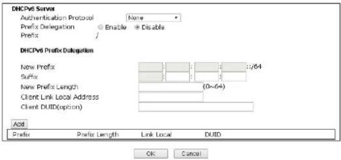
text_image
DHCPv6 Server Authentication Protocol None Prefix Delegation Enable Disable Prefix / DHCPv6 Prefix Delegation New Prefix :://64 Suffix New Prefix Length (0x-64) Client Link Local Address Client DUID(option) Add Prefix Prefix Length Link Local DUID OK CancelAdvance setting The Advanced Settings page has additional settings for Router Advertisement and enabling multiple WANs for IPv6 traffic.
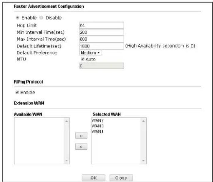
text_image
Router Advertisement Configuration Enable Disable Hop Limit 64 Min Interval Time(sec) 200 Max Interval Time(sec) 600 Default Lifetime(sec) 1800 (High Availability secondary is 0) Default Preference Medium MTU ✓ Auto 0 RIPng Protocol ✓ Enable Extension WAN Available WAN Selected WAN WAN2 WAN3 WAN4 OK CloseRouter Advertisement Configuration - Click Enable to enable router advertisement server. The router advertisement daemon sends Router Advertisement messages, specified by RFC 2461, to a local Ethernet LAN periodically and when requested by a node sending a Router Solicitation message. These messages are required for IPv6 stateless auto-configuration.
Disable - Click it to disable router advertisement server.
Hop Limit - The value is required for the device behind the router when IPv6 is in use.
Min/Max Interval Time (sec) - It defines the interval (between minimum time and maximum time) for sending RA (Router Advertisement) packets.
| Default Lifetime (sec) -Within such period of time, Vigor2926 can be treated as the default gateway.Default Preference - It determines the priority of the host behind the router when RA (Router Advertisement) packets are transmitted.MTU - It means Max Transmit Unit for packet. If Auto is selected, the router will determine the MTU value for LAN.RIPng Protocol -RIPng (RIP next generation) offers the same functions and benefits as IPv4 RIP v2.Extension WAN - In addition to the default WAN used for IPv6 traffic specified in the WAN Primary Interface in the LAN IPv6 Setup page, additional WANs can be selected to carry IPv6 traffic by enabling them in the Extension WAN section.Available WAN - Additional WANs available but not currently selected to carry IPv6 traffic.Selected WAN - Additional WANs selected to carry IPv6 traffic. |
After making changes on the Advance setting page, click the OK button to retain the changes and return to the LAN IPv6 Setup page. Be sure to click OK on the LAN IPv6 Setup page or else changes made on the Advance setting page will not be saved.
II-2-1-5 Advanced DHCP Options
DHCP Options can be configured by clicking the DHCP Server Option button on the LAN General Setup screen.
LAN >> General Setup
DHCP Server Customized Status
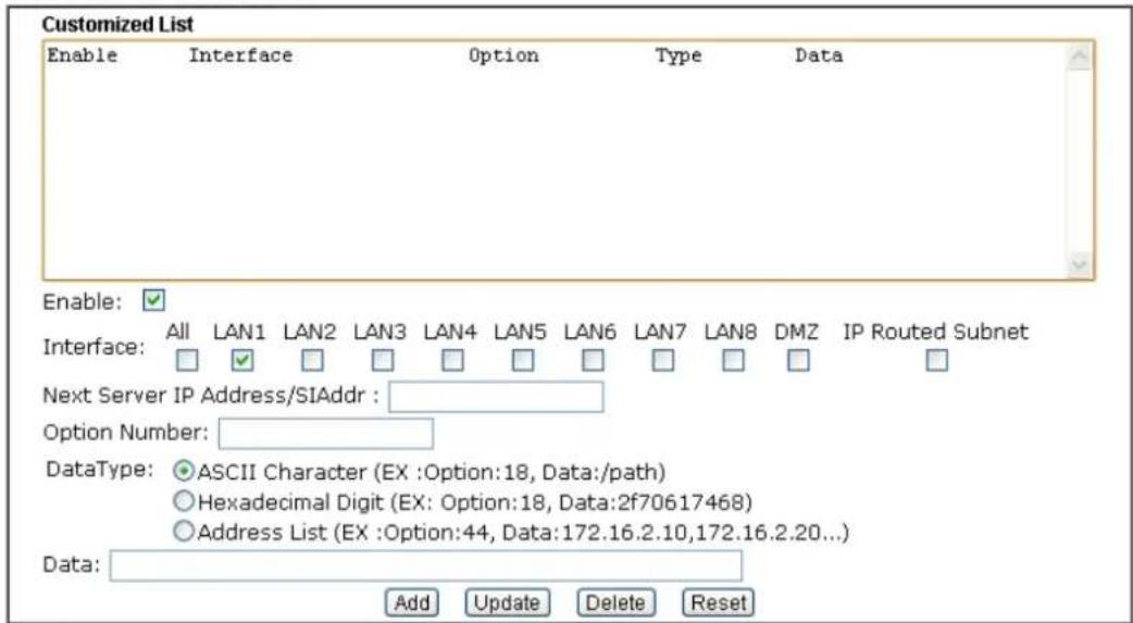
text_image
Customized List Enable Interface Option Type Data Enable: ✓ Interface: All LAN1 LAN2 LAN3 LAN4 LAN5 LAN6 LAN7 LAN8 DMZ IP Routed Subnet Next Server IP Address/SIAddr : Option Number: DataType: ASCII Character (EX :Option:18, Data:/path) Hexadecimal Digit (EX :Option:18, Data:2f70617468) Address List (EX :Option:44, Data:172.16.2.10,172.16.2.20...) Data: Add Update Delete ResetNote:
- Configuring options 44, 46 or 66 here will overwrite the settings by telnet command "msubnet".
- Configuring option 3 here will overwrite the setting in "LAN >> General Setup" Details Page's "Gateway IP Address" field.
- Configuring option 15 here will overwrite the setting in "WAN >> Internet Access >> Static or Dynamic IP" Detail Page's "Domain Name" field.
OK
Available settings are explained as follows:
| Item | Description |
| Customized List Shows all the DHCP options that have been configured in the system. | |
| Enable If selected, DHCP option entry is enabled.If unselected, DHCP option entry is disabled. | |
| Interface LAN interface(s) to which this entry is applicable. | |
| Next Server IP Address/SIAddr | Overrides the DHCP Next Server IP address (DHCP Option 66) supplied by the DHCP server. |
| Option Number DHCP option number (e.g., 100). | |
| DataType Type of data in the Data field:ASCII Character - A text string. Example: / path.Hexadecimal Digit - A hexadecimal string. Valid characters are from 0 to 9 and from a to f. Example: 2f70617468.Address List - One or more IPv4 addresses, delimited by commas. | |
| Data Data of this DHCP option. | |
To add a DHCP option entry from scratch, clear the data entry fields (Enable, Interface, Option Number, DataType and Data) by clicking Reset. After filling in the values, click Add to create the new entry.
To add a DHCP option entry modeled after an existing entry, click the model entry in Customized List. The data entry fields will be populated with values from the model entry. After making all necessary changes for the new entry, click Add to create it.
To modify an existing DHCP option entry, click on it in Customized List. The data entry fields will be populated with the current values from the entry. After making all necessary changes, click Update to save the changes.
To delete a DHCP option entry, click on it in Customized List, and then click Delete.