
KY-PZ100 - Camera JVC - Free user manual and instructions
Find the device manual for free KY-PZ100 JVC in PDF.

| Product Type | Professional PTZ Camera |
| Image Sensor | 1/2.8-inch Progressive CMOS, approx. 2.13 megapixels |
| Optical Zoom | 30x (f=4.3 mm to 129.0 mm, 35mm equivalent: 30.5 mm to 915 mm) |
| Digital Zoom | Up to 360x (when enabled) |
| Video Outputs | 3G-SDI (BNC), HDMI (Type A), Live streaming via network |
| Video Resolution & Frame Rate | 1920x1080 up to 60p; also 720p; selectable frame rates: 60p, 60i, 50p, 50i, 30p, 25p |
| Pan Range & Speed | ±175°; max 480°/s (AC adapter) / 400°/s (PoE+) |
| Tilt Range & Speed | -30° to +90°; max 300°/s (AC adapter) / 200°/s (PoE+) |
| Power Supply | DC 12V (via included AC adapter) or PoE+ (IEEE802.3at Type2) |
| Power Consumption | 1.2 A (DC 12V) / 0.4 A (PoE+) typical during recording |
| Dimensions (W x H x D) | 154 mm x 200.7 mm x 191 mm |
| Weight | Approx. 2.0 kg |
| Recording Media | microSDHC/microSDXC card (not included); QuickTime format |
| Audio Input | Φ3.5 mm stereo mini jack (mic/line, plug-in power) |
| Network Connectivity | LAN (RJ-45, PoE+), USB (for Ethernet/Wi‑Fi/cellular adapters) |
| Remote Control | Infrared remote (included); RS-232C/RS-422; IP (Standard/D‑star) |
| Preset Positions | Up to 100 (1‑10 detailed, 11‑100 simplified) |
| Operating Temperature | 0 °C to 40 °C (32 °F to 104 °F) |
| Operating Humidity | 30 %RH to 80 %RH (no condensation) |
| Safety & Maintenance | Clean with soft dry cloth; do not use benzene/thinner; ensure ventilation; use fall prevention wire when ceiling-mounted |
| Accessories Included | AC adapter, power cord, remote control, ceiling mount bracket, fall prevention wire, template |
Frequently Asked Questions - KY-PZ100 JVC
User questions about KY-PZ100 JVC
0 question about this device. Answer the ones you know or ask your own.
Ask a new question about this device
Download the instructions for your Camera in PDF format for free! Find your manual KY-PZ100 - JVC and take your electronic device back in hand. On this page are published all the documents necessary for the use of your device. KY-PZ100 by JVC.
USER MANUAL KY-PZ100 JVC
KY-PZ100WU/KY-PZ100WE KY-PZ100BU/KY-PZ100BE
INSTRUCTIONS
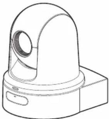
natural_image
Technical line drawing of a mechanical component with a dome-shaped top and base (no text or symbols)


Specifications and appearance of this unit are subject to change for further improvement without prior notice.
About the latest INSTRUCTIONS
Please check the latest INSTRUCTIONS, tools, etc. from the URL below.
North America:
http://pro.jvc.com/prof/main.jsp
Europe:
http://www.service.jvcpro.eu/public/
China:
http://www.jvc.com.cn/service/download/index.html
For Customer Use:
Enter below the Serial No. which is located on the body.
Retain this information for future reference.
Model No. KY-PZ100WU/KY-PZ100BU
Serial No.
Please read the following before getting started:
Thank you for purchasing this product.
Before operating this unit, please read the instructions carefully to ensure the best possible performance.
In this manual, each model number is described without the last letter (U/E) which means the shipping destination.
(U: for USA and Canada, E: for Europe) Only “U” models (KY-PZ100WU/KY-PZ100BU) have been evaluated by UL.
FOR USA
These are general IMPORTANT SAFEGUARDS and certain items may not apply to all appliances.
IMPORTANT SAFEGUARDS
- Read these instructions.
- Keep these instructions.
- Heed all warnings.
- Follow all instructions.
-
Do not use this apparatus near water.
-
Clean only with dry cloth.
-
Do not block any ventilation openings. Install in accordance with the manufacturer's instructions.
-
Do not install near any heat sources such as radiators, heat registers, stoves, or other apparatus (including amplifiers) that produce heat.
-
Protect the power cord from being walked on or pinched particularly at plugs, convenience receptacles, and the point where they exit from the apparatus.
-
Only use attachments/accessories specified by the manufacturer.
-
Use only with the cart, stand, tripod, bracket, or table specified by the manufacturer, or sold with the apparatus. When a cart is used, use caution when moving the cart/apparatus combination to avoid injury from tip-over.
-
Unplug this apparatus during lightning storms or when unused for long periods of time.
-
Refer all servicing to qualified service personnel. Servicing is required when the apparatus has been damaged in any way, such as power-supply cord or plug is damaged, liquid has been spilled or objects have fallen into the apparatus, the apparatus has been exposed to rain or moisture, does not operate normally, or has been dropped.

natural_image
Silhouette of a person pushing a ladder inside a circle (no text or symbols)CAN ICES-3 A / NMB-3 A
For USA-California Only
This product contains a CR Coin Cell Lithium Battery which contains Perchlorate Material – special handling may apply.
See www.dtsc.ca.gov/hazardouswaste/perchlorate
Safety Precautions
FOR USA AND CANADA

CAUTION
RISK OF ELECTRIC SHOCK DO NOT OPEN

CAUTION:
TO REDUCE THE RISK OF ELECTRIC SHOCK. DO NOT REMOVE COVER (OR BACK). NO USER-SERVICEABLE PARTS INSIDE. REFER SERVICING TO QUALIFIED SERVICE PERSONNEL.

The lightning flash with arrowhead symbol, within an equilateral triangle is intended to alert the user to the presence of uninsulated “dangerous voltage” within the product’s enclosure that may be of sufficient magnitude to constitute a risk of electric shock to persons.

The exclamation point within an equilateral triangle is intended to alert the user to the presence of important operating and maintenance (servicing) instructions in the literature accompanying the appliance.
This device complies with Part 15 of FCC Rules. Operation is subject to the following two conditions: (1) This device may not cause harmful interference, and (2) this device must accept any interference received, including interference that may cause undesired operation.
Changes or modifications not approved by JVC could void the user's authority to operate the equipment. This equipment has been tested and found to comply with the limits for a Class A digital device, pursuant to Part 15 of the FCC Rules. These limits are designed to provide reasonable protection against harmful interference when the equipment is operated in a commercial environment.
This equipment generates, uses, and can radiate radio frequency energy and, if not installed and used in accordance with the instructions, may cause harmful interference to radio communications. Operation of this equipment in a residential area is likely to cause harmful interference in which case the user will be required to correct the interference at his own expense.
POUR CANADA

ATTENTION
RISQUE D'ELECTROCUTION NE PAS OUVRIR

ATTENTION:
POUR EVITER TOUT RISQUE D'ELECTROCUTION NE PAS OUVRIR LE BOITER. AUCUNE PIECE INTERIEURE N'EST A REGLER PAR L'UTILISATEUR. SE REFERER A UN AGENT QUALIFIE EN CAS DE PROBLEME.

The mains plug shall remain readily operable.
- Remove the mains plug immediately if the camera functions abnormally.
WARNING:
The remote control with battery installed should not be exposed to excessive heat such as direct sunlight, fire or the like.
WARNING: TO PREVENT FIRE OR SHOCK HAZARD, DO NOT EXPOSE THIS UNIT TO RAIN OR MOISTURE.
AVERTISSEMENT : POUR EVITER LES RISQUES D'INCENDIE OU D'ELECTROCUTION, NE PAS EXPOSER L'APPAREIL A LA PLUIE NI A L'HUMIDITE.
NOTES:
- The rating plate and safety caution are on the bottom and/or the back of the main unit.
- The serial number plate is on the bottom of the unit.
- The rating information and safety caution of the AC adapter are on its upper and lower sides.
REMARQUES :
Caution on Replaceable lithium battery
The battery used in this device may present a fire or chemical burn hazard if mistreated.
Do not recharge, disassemble, heat above 100^ C ( 212^ F) or incinerate. Replace battery with Panasonic, Sanyo, Sony or Maxell CR2025.
Danger of explosion or risk of fire if the battery is incorrectly replaced.
- Dispose of used battery promptly.
- Keep away from children.
- Do not disassemble and do not dispose of in fire.
When the equipment is installed in a cabinet or on a shelf, make sure that it has sufficient space on all sides to allow for ventilation (10 cm (3-15/16") or more on both sides, on top and at the rear). Do not block the ventilation holes. (If the ventilation holes are blocked by a newspaper, or cloth etc. the heat may not be able to get out.) No naked flame sources, such as lighted candles, should be placed on the apparatus. When discarding batteries, environmental problems must be considered and the local rules or laws governing the disposal of these batteries must be followed strictly.
The apparatus shall not be exposed to dripping or splashing and that no objects filled with liquids, such as vases, shall be placed on the apparatus.
Do not point the lens directly into the sun. This can cause eye injuries, as well as lead to the malfunctioning of internal circuitry. There is also a risk of fire or electric shock.
CAUTION!
Connecting cables (Audio/Video, etc.) to this unit and leaving it on top of the TV is not recommended, as tripping on the cables will cause the unit to fall, resulting in damage.
When using the AC adapter in areas other than the USA
The provided AC adapter features automatic voltage selection in the AC range from 110 V to 240 V.
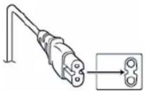
USING HOUSEHOLD AC PLUG ADAPTER
In case of connecting the unit's power cord to an AC wall outlet other than American National Standard C73 series type, use an AC plug adapter called a "Siemens Plug" as shown.
For this AC plug adapter, please contact the local dealers in your area.
Plug Adapter

natural_image
Illustration of a gray electrical plug and its corresponding terminal socket (no text or symbols)- Remove the AC adapter from the AC wall outlet when not in use.
- Do not leave dust or metal objects adhered to the AC wall outlet or AC adapter (power/DC plug).
IMPORTANT (for owners in the U.K.) Connection to the mains supply in the United Kingdom.
DO NOT cut off the mains plug from this equipment.
If the plug fitted is not suitable for the power points in your home or the cable is too short to reach a power point, then obtain an appropriate safety approved extension lead or contact the local dealers in your area.
BE SURE to replace the fuse only with an identical approved type, as originally fitted, and to replace the fuse cover. If nonetheless the mains plug is cut off be sure to remove the fuse and dispose of the plug immediately, to avoid possible shock hazard by inadvertent connection to the mains supply.
If this product is not supplied fitted with a mains plug then follow the instructions given below:
DO NOT make any connection to the Larger Terminal coded E or Green.
The wires in the mains lead are coloured in accordance with the following code:

If these colours do not correspond with the terminal identifications of your plug, connect as follows:
Blue wire to terminal coded N (Neutral) or coloured black.
Brown wire to terminal coded L (Live) or coloured Red.
If in doubt — consult a competent electrician.
CAUTIONS:
- To prevent shock, do not open the cabinet. No user serviceable parts inside.
Refer servicing to qualified personnel.
- When you are not using the AC adapter for a long period of time, it is recommended that you disconnect the power cord from AC outlet.
FOR EUROPE
This equipment is in conformity with the provisions and protection requirements of the corresponding European Directives.
This equipment is designed for professional video appliances and can be used in the following environments:
- Controlled EMC environment (for example, purpose-built broadcasting or recording studio), and rural outdoors environments.
In order to keep the best performance and furthermore for electromagnetic compatibility we recommend to use cables not exceeding the following lengths:
| Port Cable | Length | |
| DC 1.8 m | Exclusive Cable | |
| LAN | LAN Cable | 3 m |
| HDMI | Shielded Cable | 2.5 m |
| SDI | Coaxial Cable | 3 m |
| AUDIO | Shielded Cable | 4.5 m |
| RS-232C IN/OUT | Shielded Cable | 2 m |
| RS-422 | LAN Cable | 2 m |
The inrush current of this apparatus is 4.5 A.
CAUTION:
Where there are strong electromagnetic waves or magnetism, for example near a radio or TV transmitter, transformer, motor, etc., the picture and the sound may be disturbed. In such case, please keep the apparatus away from the sources of the disturbance.
CAUTION:
To avoid electric shock or damage to the unit, first firmly insert the small end of the power cord into the AC Adapter until it is no longer wobbly, and then plug the larger end of the power cord in to an AC outlet.
natural_image
Diagram of a plug with a connector, showing internal wiring and a separate view of the connector (no text or symbols present)FOR EUROPE
WARNING
This is a Class A product. In a domestic environment this product may cause radio interference in which case the user may be required to take adequate measures.
The plastics packaging bags may cause suffocation when they are covered over the head. Tear them open, and keep them away from the reach of infants and children by ensuring that they are disposed of properly.
Dear Customer
This apparatus is in conformance with the valid European directives and standards regarding electromagnetic compatibility and electrical safety. European representative of JVC KENWOOD Corporation is: JVC Technical Services Europe GmbH Konrad-Adenauer-Allee 1-11 61118 Bad Vilbel GERMANY
关于环保使用期限

环保使用期限
For KY-PZ100WE, KY-PZ-100BE
GB4943.1-2011
GB9254-2008
GB17625.1-2012
Consult your dealer as special technique is required when installing this product. Ensure that the fixing screws or nuts are tightened securely, otherwise, the unit may fall off.
Mounting to a firm place
As the unit contain parts rotating at high speed, mount it on a firm place with sufficient strength to support the vibration and weight of the unit.
Mass : Approx. 2.0 kg
If the strength is weak, the vibration will cause fuzzy images on the monitor screen. In the worst scenario, the camera may even fall off and hit somebody, resulting in serious accidents.
Mount the camera correctly
When mounting the unit to the ceiling, make sure to use a ceiling mounting bracket.
Be sure to connect the fall prevention wire and tighten the fixing screws or nuts securely.
Using the correct power and voltage
To supply power to this unit, use a DC 12 V or PoE+ (IEEE802.3at Type2) power. Make use of the correct voltage.
Use the supplied AC adapter for the DC 12 V power supply. Do not use the supplied AC adapter on other devices.
Inspect the unit regularly
Screws may be loosened due to vibration or deterioration of the mounting section. Perform regular inspections for loosened screws and check whether there is any danger of the unit falling off.
Do not hang on this product, shake it, or hang objects over it. Applying an excessive load may cause the product to fall off and result in accidents.
Do not modify this product. It may result in accidents.
Do not place any object inside the product. Placing a metallic or inflammable object may cause a fire or shock hazard.
Contents
Getting Started
Safety Precautions 4
Contents 11
Main Features 13
Precautions 14
Operation Modes 18
Names of Parts 20
DIP Switch Setting 23
Tally Lamp 25
View Remote (Live View) Screen and External
Monitor Connection Display 26
About microSD Cards 27
Compatible microSD Cards 27
Formatting (Initializing) microSD Cards ..... 28
Restoring the microSD Card 28
Clips Recorded to microSD Cards 29
Installation/Connection
Mounting the Camera to the Ceiling Mount Bracket 30
Installing the Camera on the Ceiling 31
Installing the Camera on a Desktop 32
Attaching the Camera to a Tripod 32
Connecting the Cables 33
IP Address Settings 34
Using the IP Setting Tool 34
Configuring IP Address Manually 35
Confirming the Connection 35
Using View Remote
View Remote Screen 36
Shooting
Basic Shooting Procedures 38
Selecting Video Recording Resolution, Frame
Rate and Bit Rate 38
Preset Mode 39
Pan/Tilt Operation 40
Zoom Operation 40
Focus Operation 41
Adjusting the Brightness 41
Adjusting the Iris 42
Setting the Gain 43
Setting the Electronic Shutter 44
Adjusting the White Balance 45
Adjusting the Camera Image 46
Using the Image Stabilizer 46
Audio Recording 47
Time Code and User's Bit 47
Setting Time Code Generator 48
Setting the User's Bit 50
Loop Recording 51
Menu Display and Detailed Settings
Basic Operations in Menu Screen 52
Display and Description of the Menu Screen 52
Text Input with Software Keyboard 53
Menu Screen Hierarchical Chart 54
Camera Function Menu 55
Camera Process Menu 56
Pan/Tilt Menu 57
TC/UB Menu 58
A/V Set Menu 59
Video Set Item 59
Audio Set Item 59
Network Menu 60
System Menu 65
Record Set Item 67
Display/Status Screen
Display Screen in Camera Mode 69
Status Screen 72
Connecting External Devices
Connecting External Monitor 73
Connecting to the Network
Functions of Network Connection 74
Network Connection 74
Operating Environment 74
Connecting to Network via [LAN] Terminal .. 75
Connecting to Network via [USB] Terminal .. 75
Connecting via Wireless LAN (USB) 76
Connecting via Ethernet Adapter (USB) ..... 77
Connecting via Cellular Adapter (USB) ..... 78
Importing Metadata 78
Preparing Metadata 78
Configuring the Server for Downloading ..... 79
Importing Metadata 79
Editing Metadata 80
Planning Metadata 80
Clip Metadata 81
Uploading a Recorded Video Clip 83
Deleting Recorded Clips 85
Changing Settings 87
Changing Common LAN/USB Connection Settings 88
Changing LAN Connection Settings 88
Changing USB Connection Settings 89
Changing Metadata Server Settings 90
Changing Clip Server Settings 91
Changing Live Streaming Settings 92
Managing the Network Connection Settings File 93
Saving the Connection Settings File 94
Reading the Connection Settings File ..... 95
Deleting Connection Settings 95
Loading and Saving Setup Files 96
Performing Live Streaming 97
Setting Distribution 97
Starting Distribution 99
Setting the FEC Matrix 100
Others
Error Messages and Actions 101
List of FTP Transfer Errors 101
List of Live Streaming Error Displays ..... 103
Blinking of the Tally Lamp 104
Troubleshooting 105
Specifications 107
Software License Agreement 110
Important Notice concerning the Software ..... 112
Index 113
Content of this Manual
Symbols used
Caution : Describes precautions concerning the operation of this product.
Memo : Describes reference information, such as functions and usage restrictions of this product.
: Indicates the reference page numbers and reference items.
Content of this manual
- All rights reserved by JVC KENWOOD Corporation. Unauthorized duplication or reprinting of this manual, in whole or in part, is strictly prohibited.
- Illustrated designs, specifications and other contents of this manual are subject to change for improvement without prior notice.
- microSDXC and microSDHC logos are trademarks of SD-3C and LLC.
- HDMI (High-Definition Multimedia Interface) and HDMI ^TM are trademarks of HDMI Licensing, LLC.
- QuickTime, Mac OS and Safari are trademarks of Apple Inc. registered in the U.S. and other countries.
- Google Chrome is a trademark and/or registered trademark of Google Inc.
- Microsoft and Windows are registered trademarks of Microsoft Corporation in the United States and other countries.
- The company name of Fontworks, Fontworks, and the name of the fonts are registered trademarks of Fontworks Inc.
- Zixi and the Zixi logo are trademarks of Zixi LCC.
- Other product and company names included in this instruction manual are trademarks and/or registered trademarks of their respective companies. Marks such as ^TM and ^® have been omitted in this manual.
Main Features
Enhanced network functions
In addition to the LAN terminal, you can also attach a USB adapter that supports wireless network connection to enable communication such as live streaming and remote control by connecting to the network in a wireless environment.
Not only does this product support the “Zixi” cloud service, which enables highly-reliable and stable data transmission, live streaming such as via “SMPTE 2022-1” is also possible.
The LAN terminal supports a high bit rate setting, which allows for live streaming in higher definition.
Supports simultaneous output of 1080/60p SDI, HDMI and live streaming
This product comes with a [3G-SDI] and a [HDMI] digital output terminal, which enable simultaneous output of SDI, HDMI and even live streaming videos and audio files.
Silent PTZ (pan/tilt/zoom) operation
In order for this product to handle different scenes and uses that are required of a remote-controlled camera, we incorporated a direct drive system that makes use of our in-house mechanical technology to achieve both excellent positional accuracy as well as silent operation.
Highly precise in recalling preset positions
Boasts a maximum panning speed of 480^/second ( 90^/second during preset and manual) and a maximum tilt speed of 300^/second ( 90^/second during preset and manual), while at the same time recalls a preset position that has been registered very quickly and accurately.
It is also able to store up to 100 preset positions for each camera.
Compatible with PoE+ power supply for each installation
This product supports PoE+ (Power over Ethernet Plus), which enables power supply as well as camera control and live streaming through the network simply via a LAN cable connection. It also eases installation of the camera at locations where mounting is difficult, such as a ceiling.
1/2.8-inch high-performance CMOS sensor
This product is equipped with a 1/2.8-inch high-performance CMOS sensor with an effective resolution of approximately 2.13 megapixels. It delivers high-quality Full HD video images with a low level of noise.
30x optical zoom lens
The camera comes with a 30x optical zoom lens that is able to handle shoots at huge locations such as in a hall or conference center.
High-quality in-camera recording (microSD)
You can record video images on the camera using a microSD card. It also has a loop recording feature that continues to record the audio sound and video images for a certain period of time.
Recorded videos can also be sent via FTP transfer over the network.
Equipped with an audio input terminal
This product is equipped with a [AUDIO IN] terminal. Monaural or stereo audio recording is also possible when a microphone is connected.
Comes with ceiling mounting bracket and infrared remote controller
Supports different types of remote protocols
This product supports IP (Standard/D star) and RS-232C/RS-422 (Standard/D star).
Precautions
Installation Location
■ Be sure to install the camera horizontally.
Storage and Usage Locations
- Allowable ambient temperature and humidity Be sure to use this unit within the allowable temperature range of 0 °C to 40 °C (32 °F to 104°F) and a relative humidity of 30 % to 80 %. Using this unit at a temperature or humidity outside the allowable ranges could result not only in malfunction but also serious impact on the CMOS elements as small white spots may be generated. Please exercise care during use.
■ Strong electromagnetic waves or magnetism Noise may appear in the picture or audio and/or the colors may be incorrect if this unit is used near a radio or television transmitting antenna, in places where strong magnetic fields are generated by transformers, motors, etc., or near devices emitting radio waves, such as transceivers or cellular phones.
■ Use of wireless microphone near this unit When a wireless microphone or wireless microphone tuner is used near this unit during recording, the tuner could pick up noise.
■ Inadequate heat ventilation may result in malfunction of this product. Be sure not to block vents around the product. This product discharges heat from the surface of the main unit. - Do not install it at locations directly subjected to cold air such as near the vents of air-conditioners or at locations with high temperature.
- Avoid using or placing this unit in the following places.
- Locations beyond the allowable operating humidity range of 30 %RH to 80 %RH. (Condensation is not allowed)
- Near equipment that emits strong magnetic fields, such as transformers or motors.
- Near equipment that emits radio waves, such as transceivers and mobile phones.
- Locations with excessive dust and sand.
- Locations that are subject to vibration such as inside the car or ship.
- Locations prone to moisture such as window side.
- Locations subject to steam or oil, such as kitchens.
- Special environment, such as those with combustible atmosphere.
- Locations that are subjected to radiation, X-rays, salt attack or corrosive gases.
- Locations where chemicals are used such as swimming pools.
- Hot or cold places that are beyond the allowable ambient operating temperature range.
Transportation
- Do not throw away the original box of the unit. Keep it and use it for transporting the unit in future.
The camera unit is designed to be rotated easily, secure the camera unit such that it does not rotate before transporting. Otherwise, an error may occur during camera operation.
①Face the lens upward, and secure the lens unit and the camera head with tape.
② Secure the camera head and the base at multiple positions with tape.
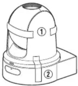
natural_image
Technical line drawing of a mechanical component with two labeled parts (① and ②), no text or symbols present.| Carrying the Camera
■ Do not drop or hit this unit against a hard object when transporting.
■ Remove the connecting cables when transporting the unit.
■ When transporting the unit, turn off the power of the system.
- Pack the unit with cushioning material so as to avoid shock when transporting.
■ Handle the unit with care and do not subject it to vibration or shock.
Power Saving
If the camera is not to be used for a long time, turn off the power of the system for safety and energy conservation reasons.
Maintenance
■ Turn off the power before performing any maintenance.
■ Wipe the external cabinet of the unit with a soft cloth. Do not wipe the body with benzene or thinner. Doing so may cause the surface to melt or turn cloudy. When it is extremely dirty, soak the cloth in a solution of neutral detergent, wipe the body with it, and then use a clean cloth to remove the detergent.
microSDHC/microSDXC Cards
■ “microSDHC/microSDXC card” is referred to as “microSD card” in this manual.
This camera recorder saves the recorded images and audio sound to the microSD card (sold separately) that is inserted into the card slot.
If the microSD card contains files recorded by devices other than this camera recorder or files that are saved from a PC, the recordable time may be shorter or data may not be properly recorded. In addition, the remaining space on the card may not increase even when files are deleted using a PC.
* Using cards other than those from Panasonic, TOSHIBA or SanDisk may result in recording failure or data loss.
Handling of microSD Cards
■ Do not remove the microSD card during data access (such as recording or formatting). And, do not turn off the power or remove the AC adapter during access.
- Do not use or store the microSD card in a place that is subject to static electricity or electrical noise.
- Do not place the microSD card near locations that are exposed to strong magnetic fields or radio waves.
- Inserting the microSD card incorrectly may result in damage of this unit or the microSD card.
We are not liable for any accidental loss of data stored on the microSD card. Please back up any important data.
■ Make use of the microSD card within the prescribed conditions of use.
Do not use it at the following locations.
Places that are subject to direct sunlight, high humidity or corrosion, places near thermal equipment, sandy or dusty places, or in a car under the sun with the doors and windows closed.
- Do not bend or drop the microSD card, or subject it to strong impact or vibration.
■ Do not splash the microSD card with water.
■ Do not dismantle or modify the microSD card.
- Do not touch the terminals with your hands or with a metal object.
- Do not allow dust, dirt, water, or foreign objects to adhere to the terminals.
■ Do not stick any label or sticker.
■ Do not use a pencil or ballpoint pen to write on the microSD card. Always use oil-based pens.
If you format (initialize) the microSD card, all data recorded on the card, including video data and setup files, will be deleted.
■ You are recommended to use cards that are formatted (initialized) on this camera recorder.
- The microSD card may be damaged if the camera recorder is not functioning correctly. Formatting (Initializing) the microSD may allow it to operate correctly.
- microSD cards that have been formatted (initialized) on another camera, computer or peripheral equipment may not function correctly. In this case, format (initialize) the microSD card on this camera recorder.
If you want to discard the microSD card by completely erasing the data inside, we recommend either using commercially available software that is specially designed for that purpose or physically destroying the microSD card with a hammer, etc. When formatting or erasing data using the camera recorder, only the file administration information is changed. The data is not completely erased from the microSD card.
■ The microSD card may pop out when it is being ejected from the slot. Be careful not to lose the card.
Encryption in Network Connection
■ Wireless LAN connections make use of an encryption function.
This encryption is designed for commercially-sold equipment, and it cannot be altered.
License Notices
MPEG LA AVC
THIS PRODUCT IS LICENSED UNDER THE AVC
PATENT PORTFOLIO LICENSE FOR THE
PERSONAL USE OF A CONSUMER OR OTHER
USES IN WHICH IT DOES NOT RECEIVE
REMUNERATION TO
(i) ENCODE VIDEO IN COMPLIANCE WITH THE AVC STANDARD ("AVC VIDEO") AND/OR (ii) DECODE AVC VIDEO THAT WAS ENCODED BY A CONSUMER ENGAGED IN A PERSONAL ACTIVITY AND/OR WAS OBTAINED FROM A VIDEO PROVIDER LICENSED TO PROVIDE AVC VIDEO.
NO LICENSE IS GRANTED OR SHALL BE IMPLIED FOR ANY OTHER USE. ADDITIONAL INFORMATION MAY BE OBTAINED FROM MPEG LA, L.L.C. SEE
HTTP://WWW.MPEGLA.COM
Copyright
■ Any recordings made on this camera recorder that are played back for profit or public preview may infringe on the rights of the owner of the recordings.
Do not use the recordings for purpose other than personal enjoyment without prior consent from the owner.
Login Password
The default password is widely known. It is very dangerous to use the password without changing it. Set a password that is not easily guessed. It is also recommended to change the password regularly.
Others
This camera will perform the initial operation of pan/tilt/zoom upon powering on.
■ The camera body may be captured in the recording depending on the pan, tilt or zoom position.
- Do not subject the lens to strong light source such as sun rays. This may cause the equipment to malfunction.
During audio input/output, noise may occur when the rotation mechanism is rotated horizontally/vertically, when zooming is performed or when the power is turned on/off. This is not a malfunction.
The pan operation range of this product is limited to ±175^ . Regardless of the function, operation is not possible beyond this range.
■ Some switching hubs of products that are equipped with intelligent features may include a broadcast/multicast suppression function. Viewing of multicast images on this product may fail if this function is enabled.
The dark areas on the screen may appear grainy or white spots may increase. When switching between color and black-and-white images, the brighter area on the screen is emphasized, which may reduce the visibility. However, this is not a malfunction.
If the power supply voltage is momentarily cut off or reduced due to lightning or turning on of the air conditioner's power, the image may be disrupted or noise interference may occur.
■ When shooting objects with a luminance difference or near a light source, ghost may occur on the screen. This is a feature of the built-in lens, and is not a malfunction.
■ The time of the internal clock may be significantly out of alignment if the power of the product is turned off for a long time or when there is prolonged power failure. If this occurs, readjust the clock time.
■ When the monitor in use has a wide display area, lines may appear at the peripheral area of the screen.
■ Operation via an infrared remote control unit may not work depending on where and how the camera is installed.
■ An afterimage can appear if you view a moving object on the monitor output, however this is not a malfunction.
- Do not insert objects other than the memory card into the card slot.
■ Do not put anything into the camera unit. Metal and flammable items entering from the connectors can result in fire or electric shock.
- Do not turn On/Off the power or remove the supplied AC adapter during recording.
The camera recorder may not show stable pictures for a few seconds immediately after the power is turned on, but this is not a malfunction.
■ Do not drop this unit or subject it to strong impact or vibration as it is a precision equipment.
■ Optical performance of lens
Due to the optical performance of the lens, color divergence phenomena (magnification chromatic aberration) may occur at the periphery of the image. This is not a camera malfunction.
■ Noise may appear in the image when switching modes.
■ Use the supplied AC adapter for the power supply (DC 12 V). Do not use the supplied AC adapter on other devices.
■ This camera recorder makes use of fonts by Fontworks Inc.
■ This camera recorder makes use of M+FONTS.
- Before starting an important recording, be sure to perform a test recording in order to confirm that a normal recording is possible.
- We shall not be liable for the loss of recordings or opportunities in the event that recording could not be performed due to a problem that arises during the use of the video camera or recorder.
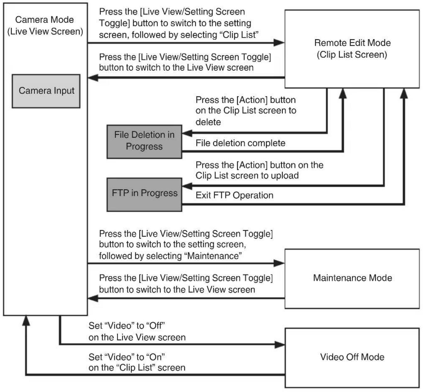
Operation Modes
This camera has four operation modes - Camera mode, Remote Edit mode, Maintenance mode and Video Off mode.
flowchart
graph TD
    A["Camera Input"] --> B["Camera Mode (Live View Screen)"]
    B --> C["Press the [Live View/Setting Screen Toggle"] button to switch to the setting screen, followed by selecting "Clip List"]
    C --> D["Remote Edit Mode (Clip List Screen)"]
    D --> E["File Deletion in Progress"]
    E --> F["Press the [Action"] button on the Clip List screen to delete]
    F --> G["File deletion complete"]
    G --> H["Exit FTP Operation"]
    H --> I["FTP in Progress"]
    I --> J["Press the [Live View/Setting Screen Toggle"] button to switch to the setting screen, followed by selecting "Maintenance"]
    J --> K["Maintenance Mode"]
    K --> L["Press the [Live View/Setting Screen Toggle"] button to switch to the Live View screen]
    L --> M["Set "Video" to "Off" on the Live View screen"]
    M --> N["Set "Video" to "On" on the "Clip List" screen"]
    N --> O["Video Off Mode"]
| Operation Mode | Description |
| Camera Mode | This is the camera shooting mode. The camera recorder starts up in Camera mode when the power is turned on.Video images from the camera are output to a browser (Live View) screen or an externally connected monitor. When a recordable microSD card is inserted, the camera recorder enters the recording standby mode.Press the [REC] button to start recording.Memo:When shifting from the Video Off mode to the camera mode, it may take a while for the camera to complete the initial operation and output the video images. |
| Remote Edit Mode | This mode enables the list display and editing of the recorded clip data through access to the clip list display page via a web browser on a PC.When youaccess via a web browser on a PC, “It is necessary to change the camera mode to "Remote Edit Mode". Change the mode.” appears on the web browser.At the same time, “Change to Remote Edit Mode?” appears on the screen of the device that is connected to the video output terminal.Selecting [Change] switches to the Remote Edit mode, and enables display of the clip list and editing of the clip metadata.(P81 [ Clip Metadata ] )(P83 [Uploading a Recorded Video Clip])Memo:If you access via the web browser of a PC while recording is in progress, the message appears after recording stops. |
| Maintenance Mode | This is a mode for running Load or Store with respect to firmware update or the setup file.Stops output from the video output terminal. (Black screen display)Memo:This mode is only available when operating from a web browser screen.Upon shifting to this mode, all card recording, live streaming and Live View operations will stop. |
| Video Off Mode | This mode indicates that operation is stopped.Stops output from the video output terminal. (Black screen display)Memo:Upon shifting to this mode, all card recording, live streaming and Live View operations will stop. |
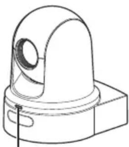
Names of Parts
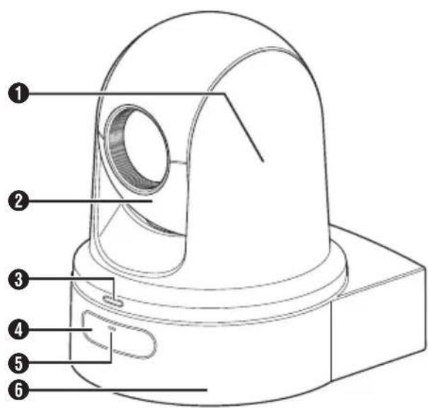
① Camera head Rotates horizontally.
② Lens section Rotates vertically.
3 Tally lamp
Turns on/off according to the menu setting and blinks depending on the status of this camera.
(☐ P25 [Tally Lamp])
(☐ P66 [Tally Lamp])
④ Infrared remote control sensor
5 POWER lamp
Lights up as follows depending on the status of this camera.
Lights up: When Video is "Off"
in red
Lights up: When Video is "On"
in green
6 Base
Bottom Section
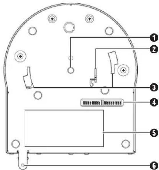
① Tripod socket hole For attaching the tripod.
② Fall prevention wire mounting hole
③ Ceiling mount bracket guide slot
④ DIP switch
Use the DIP switch to configure various settings.
(☒ P 23 [DIP Switch Setting])
⑤ Rating label ⑥ Ceiling mount bracket fixing screw hole
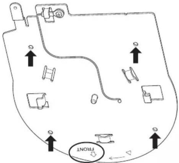
| Ceiling mount bracket
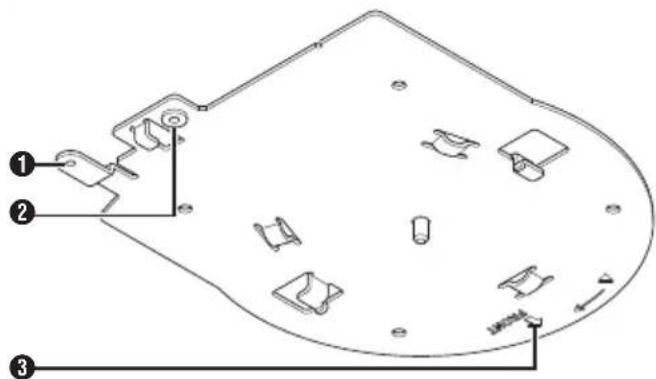
① Fall prevention wire (for ceiling) mounting hole
② Fall prevention wire (for camera) mounting hole
③ "FRONT" mark
| Terminal Section
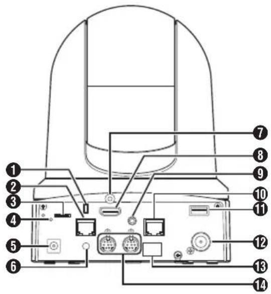
① Anti-theft wire mounting hole
② [LAN(PoE+)] LAN (PoE+) terminal For connecting the LAN cable.
③ microSD card slot
For inserting the microSD card.
( P27 [Compatible microSD Cards] )
4 Reset switch
Short press : Restores the video output setting to the default setting and restarts the camera. (*1)
Press and hold : Restores all items in the [Network] menu to their default settings. (*2)
*1 Applies to [HDMI/SDI Out] and [Resolution] in the Video Set menu, [Frame Rate] in the Network menu, [System Mode] in the [System] menu, and [Frame Rate] and [Bit Rate] in the Record Set menu.
( P59 [ HDMI/SDI Out ] )
(P59 [Resolution])
( P62 [ Frame Rate ] )
( P65 [ System Mode ] )
(P67 [Frame Rate])
(P67 [ Bit Rate ] )
*2 Works in the same way as [Reset Network Settings]. The power lamp blinks in blue while reset is in progress.
( P64 [ Reset Network Settings ] )
⑤ [DC 12V] DC input terminal
For connecting the supplied AC adapter to supply DC 12 V.
⑥ Cable clamp hole
⑦ HDMI cable fixing hole
⑧ [HDMI] HDMI terminal
Output terminal for HDMI video and audio signals.
⑨ [AUDIO IN] AUDIO input terminal For connecting the stereo mini plug.
⑩ [RS-422] RS-422 terminal
For connecting the RS-422 cable.
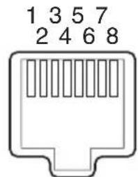
| Pin Number | Signal Name | Pin Number | Signal Name |
| 1 GND 5 TXD+ | |||
| 2 TALLY 6 RXD+ | |||
| 3 RXD-7 - | |||
| 4 TXD-8 - |
11 [USB] USB terminal
For connecting a network device.
⑫ [SDI OUT] SDI output terminal
Output terminal for SDI video and audio signals.
⑬ Infrared remote control sensor
14 [RS-232C IN/OUT] RS-232C input/output terminal
For connecting the RS-232C cable.
[RS-232C IN]: Input terminal for RS-232C remote (Mini DIN 8-pin)
[RS-232C OUT]: Output terminal for RS-232C remote (Mini DIN 8-pin)
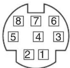
| RS-232C IN RS-232C OUT | |||
| Pin Number | Signal Name | Pin Number | Signal Name |
| 1 | DTR_IN | 1 | DTR_OUT |
| 2 | DSR_IN | 2 | DSR_OUT |
| 3 | TXD_IN | 3 | TXD_OUT |
| 4 | GND | 4 | GND |
| 5 | RXD_IN | 5 | RXD_OUT |
| 6 | GND | 6 | GND |
| 7 | IR_OUT | 7 | NC |
| 8 | IR_OUT | 8 | NC |
Infrared Remote Control
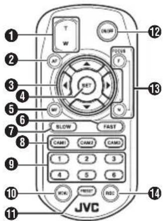
① Zoom button Pressing the button at the T end moves the zoom lens toward the telephoto range and the angle of view becomes narrower. Pressing the button at the W end moves the zoom lens toward the wide-angle range and the angle of view becomes wider.
2 AF button Sets the camera to the Auto Focus mode.
3 Pan/Tilt, Menu operation button Moves the display area. Moves the cursor when the menu is displayed.
4 SET button Restores the display area to the default position. Functions as a confirmation button when the menu is displayed.
5 MF, Cancel button Sets the camera to the Manual Focus mode. Functions as a cancel button when the menu is displayed.
6 FAST button Sets pan/tilt and zoom to high speed. Short press : High speed mode Press and hold : Maximum speed mode
7 SLOW button Sets pan/tilt and zoom to low speed. Short press : Low speed mode Press and hold : Minimum speed mode
8 CAM1 to CAM3 buttons Press and hold to select the camera to operate.
Memo :
- Configure the IR ID setting in [Main Menu]→[System]→[IR ID].
- In the event that the [IR ID] setting is not consistent with the selection of the CAM1 to CAM3 buttons, the POWER lamp on the camera will appear blinking in orange.
9 PRESET number button
Moves the display area to the recorded pan, tilt or zoom position.
10 MENU button
Press and hold to open the menu for the camera unit.
11 PRESET button To be used concurrently with the PRESET number button. Stores the current pan, tilt or zoom position in the PRESET number.
12 ON/OFF button Pressing and holding the button disables HDMI and SDI output as well as operation from the remote control unit. Pressing and holding the ON/OFF button again restores the camera to the camera mode.
13 FOCUS button Use the F button to adjust focus toward the far end and the N button to adjust toward the near end during manual focus.
14 REC button Saves recording to the microSD card on the camera unit. Pressing the button while recording is in progress stops the recording.
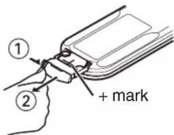
Memo :
- When using the remote control unit for the first time, remove the battery insulation film before use.
- The remote control unit uses one "CR2025" lithium battery.
Make sure to load the battery in the correct +/- orientation.
Caution :
- Do not place the remote control at a location that is subject to high temperature. Otherwise, the remote control may be deformed, thus resulting in malfunction.
- Place the batteries at a location that is out of reach of children. In the event that the battery is swallowed by mistake, consult a doctor immediately.
- Do not throw the batteries into fire or place them at a location that is subject to high temperature. Otherwise, the batteries may explode.
- When replacing the lithium battery, use one that is of the same model or type. Using a different type of battery may cause it to explode.
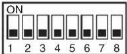
DIP Switch Setting
Configure the DIP switch before installing this unit.
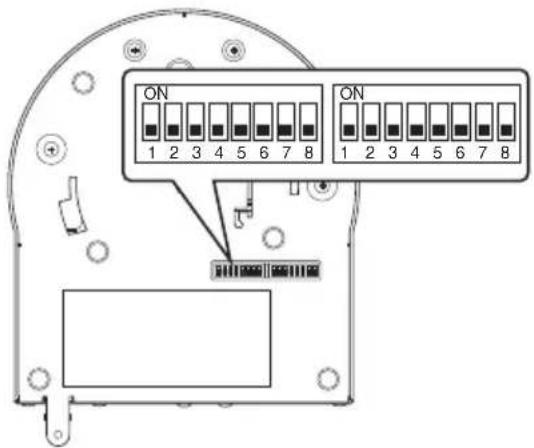
| Switch | Bit Function Description Remarks | |||
| Left 1 S | Select | communication mode | For selecting a communication mode. | OFF: LAN; ON: Serial |
| 2 to 4 | Select protocol For selecting protocols. Setting | values when LAN is set:0: JVC; 1: D star; 2: Standard; 3 to 7: ReservedSetting values when Serial is set:0: Reserved; 1: D star; 2: Standard; 3 to 7: Reserved* For latest information on compatibility, please visit our website. | ||
| 5 to 7 | Set camera address | For selecting a camera address. | Setting values when bit2 to bit 4 is set to “Standard”:0: AUTO; 1 to 7: Cameras 1 to 7 | |
| 8 | Baud rate For selecting a baud rate for serial communication. | OFF: 9600 bps, ON: 38400 bps | ||
| Right 1 | RS-232C,RS-422/485 | For selecting a communication terminal for serial communication. | OFF: RS-232C; ON: RS-422/485 | |
| 2 Remote control infrared output | For selecting an infrared output. | OFF: No output; ON: Outputs IR_OUT from RS-232C IN terminal Directing the infrared remote control that comes with commercially available controllers toward the camera allows you to operate the commercially available controller (connected via RS-232C). | ||
| 3 to 7 Service terminals Set them to OFF during use. | - | |||
| 8 RS-422/485 termination | RS-485 receiving end 110 Ω termination | OFF: Do not terminate; ON: Terminate | ||
* Combination of bit and setting values of DIP switches 2 to 4 and 5 to 7
Setting Value (The following is for DIP switches 2 to 4. It is the same for DIP switches 5 to 7)
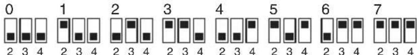
Bit
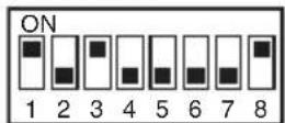
■ Connection example 1: IP control
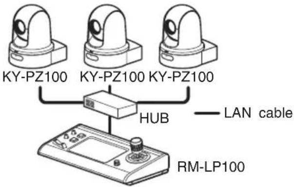
| Switch | Bit Function Settings | ||
| Left 1 Select | communication mode | Set to LAN (OFF). | |
| 2 to 4 Select protocol Set | to JVC (0). | ||
LeftRight
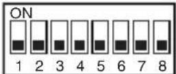
■ Connection example 2: Daisy chain connection of commercially available controller (standard protocol) with RS-232C
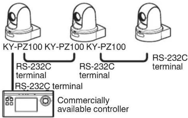
LeftRight
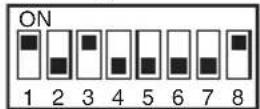
| Switch | Bit Function Settings | ||
| Left 1 S | Select | communication mode | Set to Serial (ON). |
| 2 to 4 | Select protocol | Set to Standard (2). | |
| 5 to 7 | Set camera address | Set AUTO (0) or 1 to 7. (Make sure that there are no duplicate address numbers.) | |
| 8 Baud rate | Set | to 9,600 bps (OFF) or 38,400 bps (ON) according to the controller. | |
| Right | 1 RS- | 232C, RS-422/485 | Set to RS-232C (OFF). |
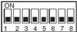
■ Connection example 3: Connection of commercially available controller (standard protocol) with RS-422
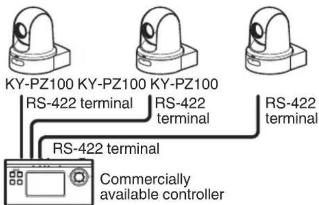
LeftRight
| Switch | Bit | Function | Settings |
| Left 1 | Select communication mode | Set to Serial (ON). | |
| 2 to 4 | Select protocol | Set to Standard (2). | |
| 8 | Baud rate | Set to 9,600 bps (OFF) or 38,400 bps (ON) according to the controller. | |
| Right | 1 | RS-232C, RS-422/485 | Set to RS-422/485. |
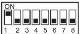
Tally Lamp
This is the indicator lamp for recording and warning.
The operation changes according to the menu settings.
The lamp appears blinking such as when the remaining level of the microSD card is running low, or when a system error occurs on the camera.
* To configure the setting, go to [Main Menu] → [System] → [Tally Lamp].
(▶ P66 [ Tally Lamp ] )
natural_image
Technical line drawing of a mechanical component with a dome-shaped top and base (no text or symbols)Tally lamp
Memo :
- Blinking takes priority over lighting up.
- You can adjust the brightness of the tally lamp in [Main Menu] [System] [Tally Lamp] [Brightness].
(→ P66 [ Brightness ] ) - When [System] [Loop Rec] is set to "On", alarm and warning displays when there is insufficient or no microSD card space will not be shown.
- When [Main Menu] [System] [Tally Lamp] is set to "External" or "Off", alarm and warning displays when there is insufficient or no microSD card space will not be shown.
| Display Type | Set Status Menu Setting Tally Lamp Status | ||
| Information Running with menu settings (recording/live streaming/external control) | Other than “Off” Lights up | ||
| Alarm If power | supplied from the LAN terminal is not PoE+ | None Blinks once in 1 | second |
| Insufficient space inside microSD card (Remaining recording time is less than 3 minutes) | RecordRecord/Livestreaming | ||
| Live streaming communication error or waiting to be connected | Live streamingRecord/Livestreaming | ||
| Warning System error None Blinks twice in 1 | second | ||
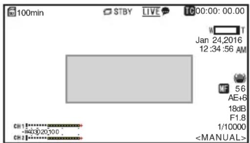
View Remote (Live View) Screen and External Monitor Connection Display
During shooting, information such as the camera status, microSD card and time code cannot be displayed overthe video image on the screen of the externally connected monitor or Live View screen.
Display Screen in Camera Mode
- When in the Camera mode, various information appears on the display screen when [Main Menu] [System] [Information Display] is set to "On".
( P65 [ Information Display ] )
( P69 [Display Screen in Camera Mode] ) - You can specify where to send the output to in [Main Menu] [System] [Information Display] [Output].
(P65 [ Output ] )
Status Screen
- This screen allows you to check the current settings.
- To display the status screen, follow the steps below.
Infrared : Press and hold the MENU button to Remote display the menu screen, followed Control by pressing the MENU button again. View : Open the [MENU] tab and click the Remote [MENU] button twice. - Use the cross-shaped keys (◀) to switch between the screens.
Remote Edit Mode Screen
This is a mode for accessing the page for editing the metadata that is recorded in a clip via a web browser on a PC.
(→ P80 [Editing Metadata])
( P83 [Uploading a Recorded Video Clip] )
(▶ P85 [Deleting Recorded Clips])

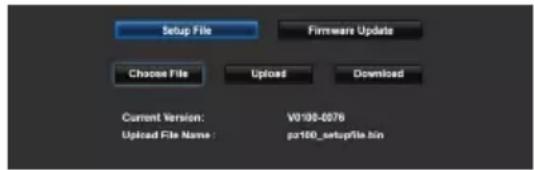
Maintenance Mode Screen
This is a mode for running Load or Store with respect to firmware update or the setup file.
| Warning Display
Displays warnings on the display screen (Camera mode).
( P101 [Error Messages and Actions] )
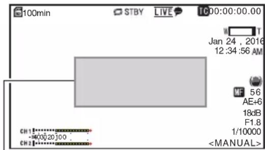
Warning Display Area
| Video Off Mode Screen
- This mode indicates that operation is stopped.
- No screen display in the Video Off mode.
About microSD Cards
| Compatible microSD Cards
Bit Rate Setting and Usable microSD Card Combinations
| System Format Bit Rate | Usable microSD Card | ||
| HD QuickTime | 50M | Class 10 or higher | |
| 35M28M18M5M | Class 6 or higher | ||
Memo :
- To use a microSDHC card, set [4GB File Spanning(SDXC)] to "On".
( P68 [ 4GB File Spanning(SDXC) ] )
Caution :
- Using cards other than those from Panasonic, TOSHIBA or SanDisk may result in recording failure or data loss.
- If an UHS-I card with no classification indication is used, it may not be possible to perform recording.
Estimated Recordable Time of microSD Cards
The estimated recordable time is only a guide. Differences may occur depending on the condition of the microSD card in use.
( P67 [ Frame Rate ] )
( P67 [ Bit Rate ] )
| Frame Rate (*1) | 60p, 60i, 50p, 50i | 60i, 30p, 50i, 25p | 60p, 50p | 60i, 30p, 50i, 25p | 60i, 50i |
| Frame Rate (*2) | - | 60p, 50p | - | 60p, 50p, 30p, 25p | 30p, 25p |
| Bit Rate 50M | 35M | 28M | 18M | 5M | |
| 4GB 9 12 15 23 | 84 | ||||
| 8GB 18 25 31 47 | 170 | ||||
| 16GB 36 50 62 95 | 340 | ||||
| 32GB 72 100 125 | 190 | 680 | |||
| 64GB (SDXC) | 145 | 200 | 250 | 380 | 1360 |
| 128GB (SDXC) | 290 | 400 | 500 | 760 | 2720 |
(Unit: minute)
*1 When [Main Menu] → [System] → [System Mode] is set to "1080/60" or "1080/50"
*2 When [Main Menu] → [System] → [System Mode] is set to "720/60" or "720/50"
Memo :
- If the microSD card contains files recorded by devices other than this camera recorder or files that are saved from a PC, the recordable time may be shorter or data may not be properly recorded.
- Up to 600 clips can be recorded to one microSD card on this unit. When 600 clips are recorded to one card, the remaining space is displayed as 0 min regardless of the estimated recordable time, and no further recording can be performed.
Inserting an microSD Card
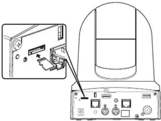
natural_image
Diagram of a computer monitor rear panel showing internal components and an inset view of the front panel (no text or symbols present)1 Insert the microSD card into the slot according to the orientation indicated by the illustration.
Removing the microSD Card
1 Push the microSD card and remove it from the slot.
Caution :
- Data may be lost if you turn off the power of the camera recorder or remove the microSD card when it is being accessed. All data recorded on the card, including the file that is being accessed, may be corrupted. To turn off the power or remove the card, wait for at least 20 seconds after the recording operation has stopped.
- The microSD card may not be recognized if you insert and remove the card within a short time. When this happens, remove the card and wait for a few seconds before you reinsert.
| Formatting (Initializing) microSD Cards
When the following cards are inserted, [!FORMAT] appears at the remaining media display area.
Format the card using the camera recorder menu.
- Unformatted microSD cards
- microSD cards formatted under different specifications
* For details of the menu operation, refer to [Basic Operations in Menu Screen] (P 52).
Caution :
- Be sure to format the microSD card on this camera. microSD cards formatted on a PC or other peripheral equipment cannot be used on this camera.
1 Select [System] → [Media] → [Format Media].
( P65 [ Format Media ] )
2 The status of the selected microSD card appears.
3 Select [Format] and press the Set button (Set).
2 The status of the selected microSD card appears. 3 Select [Format] and press the Set button (Set).
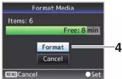
4 Formatting starts.
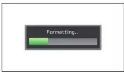
5 Formatting is complete.
When formatting is complete, "Complete" appears and the camera recorder returns to the [Format Media] screen.
Memo :
- Formatting cannot be performed in the following cases.
- Recording is in progress on the microSD card to be formatted.
• A microSD card is not inserted.
Caution :
- If you format the microSD card, all data recorded on the card, including video data and setup files, will be deleted.
Restoring the microSD Card
It is necessary to restore the microSD card if an abnormality occurs to the data in the card due to some reasons.
[! RESTORE] appears in the remaining media level display area and restoring runs automatically when a microSD card that requires restoring is inserted.
[RESTORE:XXX%] appears in the remaining media level display area while restoring is in progress.
To restore manually, follow the steps below.
1 Select [System] → [Media] → [Restore Media].
3 Restoring is complete.
- When restoring is complete, "Complete" appears and the camera recorder returns to the [Restore Media] screen.
- When no media that requires restoring is inserted, the camera recorder returns to the [Media] menu screen.
- When restoring is complete, "Complete" appears and the camera recorder returns to the [Restore Media] screen. - When no media that requires restoring is inserted, the camera recorder returns to the [Media] menu screen.
Caution :
- [Restore Media] can only be selected in Camera mode. However, it cannot be selected while the camera recorder is recording. Select [Restore Media] in Camera mode when the camera recorder is not recording.
- [Restore Media] does not restore the microSD card to its original states completely. If restoring fails, replace or format the microSD card. Take note that formatting erases all the information inside the microSD card.
- Restoring cannot be performed in the following cases.
- Camera recorder is recording in progress.
• A microSD card is not inserted.
| Clips Recorded to microSD Cards
Folders in the microSD Card
Images recorded are saved to a "DCIM" folder that is automatically generated inside the microSD card.
Memo :
- By formatting(initializing) the microSD card from the [Format Media] menu on the camera recorder, folders required for recording in the current [System] settings will be generated.
Caution :
- When a clip inside the folder is moved or deleted using the Explorer (Windows) or Finder (Mac), recording to the microSD card may fail if formatting (initializing) of the card is not performed.
Clip (Recorded Data) and Clip Name
- When recording is stopped, the images, audio and accompanying data which are recorded from start to stop are recorded as one "clip" on the microSD card.
- An 8-character clip name is automatically generated for the recorded clip. ("Clip Name Prefix" + "Clip Number")
ABCG0001
Clip Number A number in automatic ascending order is assigned in the recording order. The Clip Number can be reset in the menu.*
Clip Name Prefix (any four alphanumeric characters) This is set to "xxxG" ("xxx" denotes the last 3 digits of the serial number) by default.
* [Clip Set] → [Reset Clip Number] (→ P68 [ Reset Clip Number ] )
Memo :
- Before recording starts, you can set any characters for the clip name prefix by using [Main Menu] [System] [Record Set] [Clip Set] [Clip Name Prefix].
(▶ P68 [ Clip Name Prefix ] ) - Changes cannot be made after recording.
Recorded Clips
- The video recordings might be split into multiple files in some cases.
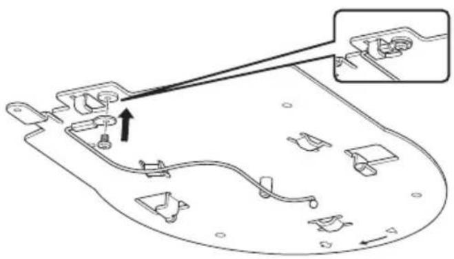
Mounting the Camera to the Ceiling Mount Bracket
- Be sure to put on protective glasses to protect your eyes from falling objects when mounting the camera.
- Be sure to place the base of the camera horizontally. The camera will not operate properly if it is slanted.
Memo :
- The ceiling mount bracket is not necessary when the camera is installed on a desktop or attached to a tripod.
- If necessary, make a hole (Φ40 mm) to route the connection cable and fall prevention wire (ceiling) into the ceiling.
Caution :
- The fall prevention wire (for ceiling) is not supplied. Make use of the wire while taking note of its length, strength, pull and material (insulation).
- Attach the fall prevention wire (ceiling) to a place with sufficient strength (ceiling slab, etc.).
- Take note of the length, strength, pull and material (insulation) of the fall prevention wire (for ceiling) and use one with a wire strength of 150 N (15 kg) or more.
- The inner diameter of the ring section of the fall prevention wire (ceiling) mounted on the camera should be above 3mm but below 4mm , the outer diameter should be 9mm and below, and the thickness 2mm and below.
1 Fix the fall prevention wire (camera) to the ceiling mount bracket using the screw (M2.6) provided.
2 Place the supplied template against the ceiling, and fasten the ceiling mount bracket with four screws (M4 wooden screws: Φ4.1).
- Prior to mounting, check the "FRONT" mark on the ceiling mount bracket to ensure that it is facing the same direction as the front of the camera.
- Check that the screws are tighten securely when mounting is completed.
Caution :
- The fall prevention wire (camera) is designed exclusively for hanging this product. Do not load anything other than this product.
Installing the Camera on the Ceiling
1 Set the DIP switch.
- Set the DIP switch prior to mounting the camera to the ceiling mount bracket.
2 Insert an microSD card.
- Insert the card as necessary during installation.
3 Attach the fall prevention wire (camera), which is fixed to the ceiling mount bracket, to the camera.
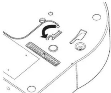
- Insert the tip of the fall prevention wire (camera) to the groove of the camera, and move it toward the direction indicated by the arrow. - Check that the fall prevention wire (camera) is fixed securely to the camera.
4 Mount the camera to the ceiling mount bracket.
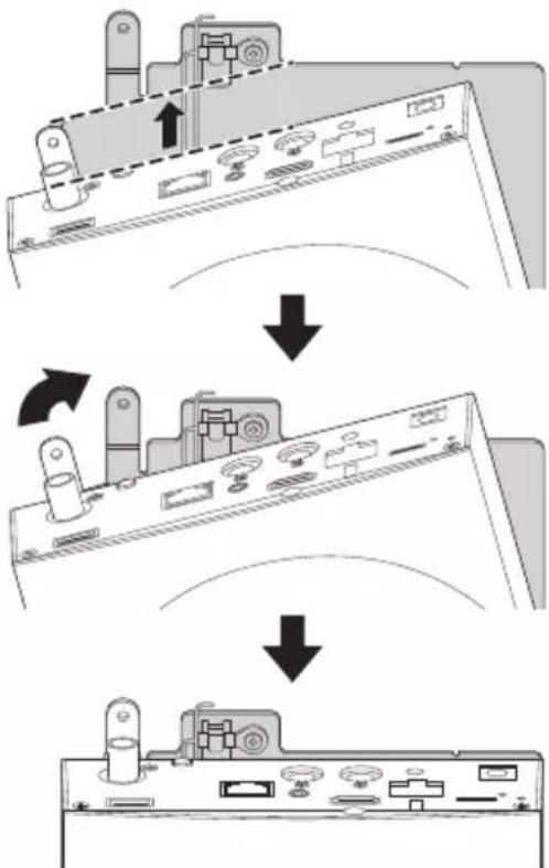
flowchart
graph TD
    A["Initial Setup"] --> B["Intermediate Setup"]
    B --> C["Final Assembly"]
    style A fill:#f9f,stroke:#333
    style B fill:#ccf,stroke:#333
    style C fill:#cfc,stroke:#333
- Align the cutout of the ceiling mount bracket and the line indicated on the camera. Press the camera unit to insert, and then turn the camera clockwise.
5 Fix the camera and the fall prevention wire (ceiling) on the ceiling mount bracket using the provided screw (M3).
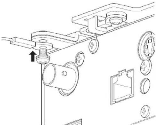
natural_image
Technical line drawing of a mechanical assembly with no visible text or symbols- Check that the screws are tighten securely when mounting is completed.
6 Connect the adapter to the [USB] terminal.
- When needed, connect the adapter according to the intended purpose. (P75 [Connecting to Network via [USB] Terminal])
Connect the cables after these procedures.
Installing the Camera on a Desktop
- Set the DIP switch prior to installing the camera.
- Place the camera on a flat surface.
- Be sure to place the base of the camera horizontally. The camera will not operate properly if it is slanted.
Memo :
- The use of ceiling mount bracket is not required.
Caution :
- Do not move the camera while the power of the system is on. Doing so may result in malfunctions or accidents.
- Do not hold the camera head while carrying the camera.
Connect the cables after these procedures.
Attaching the Camera to a Tripod
- Set the DIP switch prior to installing the camera.
- Attach a tripod using the screw hole at the bottom of this product. (1/4-20UNC, ISO1222 (6.35 mm))
- To prevent the camera recorder from falling off, which may result in injuries or damages, read the "INSTRUCTIONS" of the tripod to be used and make sure that it is securely attached.
- To ensure proper pan/tilt operation, set the tripod such that the camera is parallel to the horizontal surface.
Memo :
- The use of ceiling mount bracket is not required.
Caution :
- If the camera recorder exceeds the weight limit of the tripod, do not mount it on the tripod.
- Use the tripod on a stable surface.
- Use screws with a screw length between 4.5 mm and 7 mm.
- Do not install the camera at a high location when the camera is attached to a tripod.
Connect the cables after these procedures.
Connecting the Cables
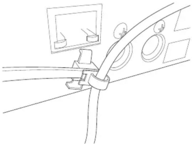
1 Connect the power cable.
- To supply power from an AC adapter, connect an AC adapter cable.
- To supply power via PoE+, proceed to the next step without connecting an AC adapter cable.
- Fix the AC adapter cable with a cable clamp.
natural_image
Line drawing of a cable clamp securing a wall-mounted device (no text or symbols)2 Connect the LAN cable.
3 Connect the SDI cable. (Optional)
4 Connect the HDMI cable. (Optional)
5 Connect the microphone cable or audio cable. (Optional)
6 Remove the protective sheet attached to the infrared remote control sensor.
Caution :
- For safety reasons, turn on the power only after ensuring that all the connections are in place.
- Do not supply power through the AC adapter cable and LAN cable at the same time.
Warning
To supply power to this unit, use a DC 12 V or PoE+ (IEEE802.3at Type2) power. Make use of the correct voltage. Supplying a power beyond the rated value may result in failures, smoke or fire. If the camera breaks down, turn off the power and contact our service center immediately. When a power beyond the rated value is supplied, the internal components may be damaged even if no abnormality is found on the appearance and operation of the camera. Please contact our service center immediately for servicing (charged separately).
IP Address Settings
Using the IP Setting Tool
- Connect the camera to be configured to the network via the LAN terminal.
- Download the "IPSettingTool" from the URL stated on the cover page.
- Connect the computer for executing the "IPSettingTool" to the network to establish communication with the camera to be configured.
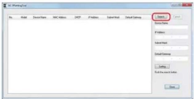
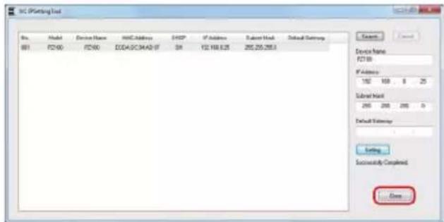
1 Start up "IPSettingTool".
2 Click the [Search] button.
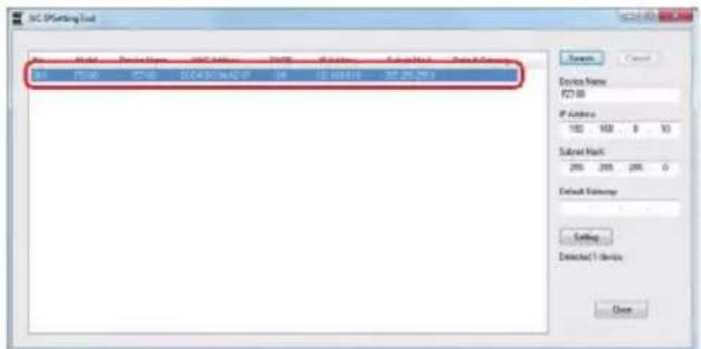
3 Select from the list the camera to be configured.
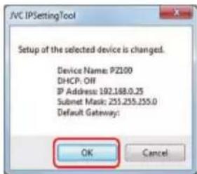
4 Enter the respective network setting items and click the [Setting] button. After a confirmation screen appears, click [OK].
- "Default Gateway" can be omitted.
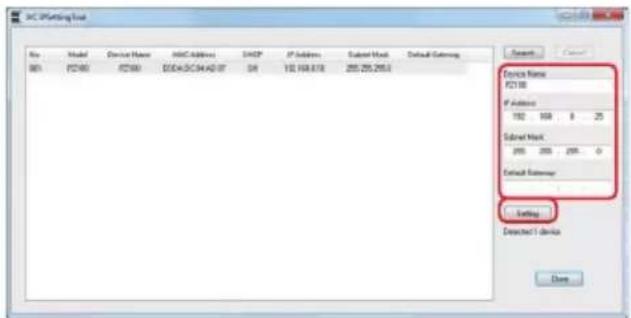
- If setting is successful, the search list display will be updated.
- If there are multiple cameras to be configured, repeat steps 3 to 4 for each camera.
Memo :
- When the "Failed in the Setting." message is displayed, check the setting details and review the connecting device then try again.
5 Click the [Close] button to exit.
Memo :
- Cameras with the same IP address as the computer for configuring the IP address cannot be detected.
- Make sure that there is no duplication in the IP address configured for each camera.
- When a firewall has been installed, change the setting to allow communication access by the "IPSettingTool".
- The "IPSettingTool" runs on Windows. For more information on setting the IP address in an environment other than Windows, please refer to the [Configuring IP Address Manually] (P 35).
Configuring IP Address Manually
Display the menu screen on the external monitor using the infrared remote control to set the IP address.
- Connection via the LAN terminal (P75 [Connecting to Network via [LAN] Terminal])
- Connection via the USB terminal (P75 [Connecting to Network via [USB] Terminal])
Confirming the Connection
Operating Environment
Operation has been verified for the following environments.
- Computer
• OS: Windows 7
Web browser: Google Chrome
• OS: Windows 10
Web browser: Google Chrome
• OS: Mac OS X 10.11
Web browser: Safari
1 Start up the web browser on the terminal you wish to connect to the camera recorder, and enter the IP Address in the address field.
• (Example: http://192.168.0.25)
Memo :
- The default IP address of the camera is as follows. LAN terminal: 192.168.0.10 USB terminal (Ethernet adapter): 192.168.1.10
2 Enter the user name and password.
- Enter the user name (jvc) and the password (initial password: 0000) on the login screen to display the Live View screen.
Memo :
- The Live View screen is not displayed when [Main Menu] [Network] [Web] [Web Access] is set to "Off".
- Be sure to change the login password on first login.
( P60 [ Login Password ] )
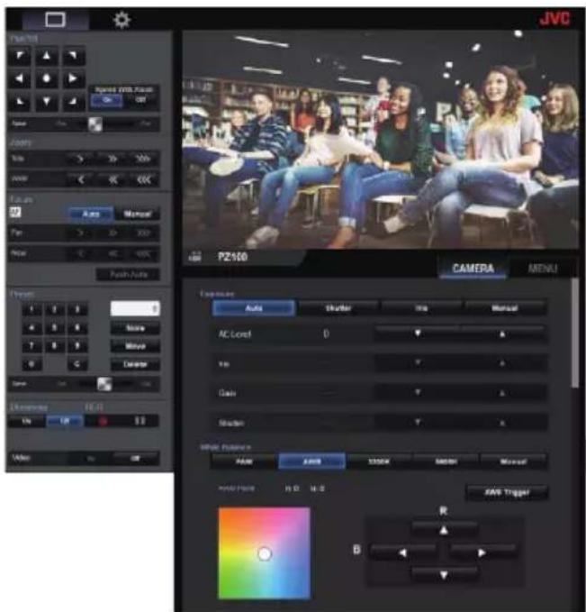
View Remote Screen
Camera Operation
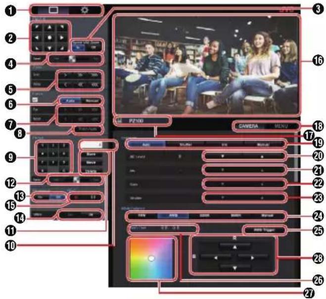
1 Live View screen/Settings screen selection button
Switches between the Live View screen and Settings screen.
For details on the setting screen, please refer to [Changing Settings] (P 87).
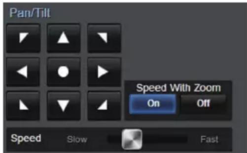
2 Pan/Tilt operation button
Arrow : Moves the camera in the direction buttons of the arrow.
● button : Restores the display area to the default position.
3 Pan/Tilt speed/Zoom selection button
On : Increasing the zoom ratio to a higher value decreases the Pan/Tilt speed.
Off : Pan/Tilt speed remains constant regardless of the zoom ratio.
4 Pan/Tilt speed setting bar For setting the Pan/Tilt speed.
⑤ Zoom operation button Enables zooming operations.
6 AF/MF selection button
Auto : Sets to auto focus.
Manual : Sets to manual focus.
⑦ Focus operation button
Enables focusing operations.
Enabled only during manual focus.
8 One-Press AF button
Pressing the button adjusts the focus automatically.
Enabled only during manual focus.
9 Preset number input button
Enter a preset number from 1 to 100.
Pressing the C button clears the input.
⑩ Preset number display Displays the preset number you have entered.
⑪ Preset operation button
Store : Registers the preset number. A confirmation message appears before registration is executed. Move : Executes the preset operation. Delete : Executes the delete operation. A confirmation message appears before registration is executed.
12 Preset speed setting bar
For setting the preset moving speed for the pan/tilt operation.
13 Live streaming On/Off button
Switches live streaming between On/Off.
Memo :
- The LiveView screen is not displayed while live streaming is in progress.
14 Video On/Off button
On : Pressing this button in the Video Off mode restores the pan/tilt setting to the position before entering the Video Off mode and outputs the camera image. Off : Stops camera output after moving the pan/tilt position to the rear and facing down. (Switches to the Video Off mode.)
15 Record Start/Stop button
● : Starts recording ■ : Stops recording
16 Live View screen Displays the Live View screen.
⑰ Camera name Displays the name of the preset camera on the setting screen.
18 Camera operation/menu operation selection tab Pressing the tab switches between camera operation and menu operation. ( P37 [Menu Operation] )
19 Exposure selection button Auto : Adjusts the brightness automatically. Shutter : Switches to shutter priority (manual for shutter and auto for all others) operation.
Iris : Switches to iris priority (manual for iris and auto for all others) operation.
Manual : Switches iris, gain and shutter to manual operation.
20 AE Level adjustment button Adjusts the AE level. Enabled only when the [Exposure] selection button is not set to "Manual".
▲ : Increases brightness.
▼ : Decreases brightness.
21 Iris adjustment button Adjusts the Iris. Enabled only when the [Exposure] selection button is set to "Manual" or "Iris".
▲ : Sets the iris to the Open side.
▼ : Sets the iris to the Close side.
22 Gain adjustment button Adjusts the gain level. Enabled only when the [Exposure] selection button is set to "Manual".
▲ : Increases the gain level.
▼ : Decreases the gain level.
23 Shutter adjustment button Adjusts the shutter speed. Enabled only when the [Exposure] selection button is set to "Manual" or "Shutter".
▲ : Increases the shutter speed.
▼ : Decreases the shutter speed.
24 White Balance mode button FAW : Switches the camera to the Automatic White Balance mode. The white balance is automatically adjusted according to the color temperature of the lighting on the object.
AWB : Pressing the [AWB Trigger] button automatically adjusts the white balance.
3200K : Sets the color temperature to 3200K.
5600K : Sets the color temperature to 5600K.
Manual : For adjusting R gain/B gain manually.
25 [AWB Trigger] button Pressing the button adjusts the white balance automatically. Enabled only when the [White Balance] selection button is set to AWB.
26 White Balance adjustment panel display
- Displays the AWB paint adjustment value when the [White Balance] mode selection button is set to "AWB".
Example: AWB Paint ----R:±32 B:±32
- Displays the R/B gain adjustment value when the [White Balance] mode selection button is set to "Manual".
Example: R/B Gain ----R: 0 to 255 B: 0 to 255
- Not displayed if the [White Balance] mode selection button is not set to any of the above.
27 R/B Gain adjustment panel
- Displays Color Panel 1 when the [White Balance] mode selection button is set to "AWB". Adjust AWB paint to a value within the ±32 range using the R/B Gain adjustment button.
- Displays Color Panel 2 when the [White Balance] mode selection button is set to "Manual". Adjust R/B gain to a value between 0 and 255 range using the R/B Gain adjustment button.
- A monochrome panel is displayed and adjustment is disabled when the [White Balance] mode selection button is not set to any of the above.
28 R/B Gain adjustment button
▲ : Increases R gain
▼ : Decreases R gain
◀ : Decreases B gain
▶ : Increases B gain
Menu Operation
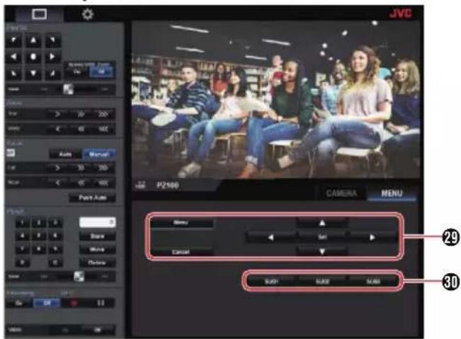
29 Menu operation button For operating the camera menu.
30 SUB 1 to SUB 3 buttons
Executes the displayed function if SUB 1 - SUB 3 is displayed on the operation guide during menu operation.
Basic Shooting Procedures
You are recommended to operate this camera by connecting it to a PC or a controller.
Preparations
1 Supply power to the camera via a LAN cable or AC adapter.
(→ P33 [Connecting the Cables])
2 Insert an microSD card.
( P27 [Inserting an microSD Card] )
3 Configure the IP address of the camera.
Using IPSettingTool allows you to configure the IP address easily.
( P34 [Using the IP Setting Tool] )
You can also configure the IP address manually without using the IPSettingTool.
( P35 [Configuring IP Address Manually] )
4 Check the connection.
(→ P35 [Confirming the Connection])
Memo :
- The supplied infrared remote control unit might not work depending on the conditions of installation.
- Descriptions on the operation of this camera focus on operation via a web browser (Live View) screen on a PC.
Selecting Video Recording Resolution, Frame Rate and Bit Rate
You can select the resolution of the recorded video, frame rate and bit rate on this camera by displaying the web browser (Live View) screen or the menu screen on an external monitor.
( P52 [Displaying the Menu Screen] )
Selecting a System Definition
1 Select a resolution in [Main Menu] → [System] → [System Mode].
Select a frame rate
Frame rates that are selectable vary according to the setting in System Mode.
(P65 [ System Mode ] )
| System Mode Frame Rate | |
| 1080/60 60p, 60i, 30p | |
| 1080/50 50p, 50i, 25p | |
| 720/60 60p, 30p | |
| 720/50 50p, 25p | |
Select a bitrate
Bitrates that are selectable vary according to the settings in [System Mode] and [Frame Rate].
( P65 [ System Mode ] )
(P67 [Frame Rate])
| System Mode Frame Rate Bit | Rate | |
| 1080/60, 1080/50 | 60p, 50p 50M | , 28M |
| 1080/60, 1080/50 | 60i, 50i 50M, | 35M, 18M,5M |
| 1080/60, 1080/50 | 30p, 25p 50M | , 35M, 18M |
| 720/60, 720/50 60p, 50p 35M, 18M | ||
| 720/60, 720/50 30p, 25p 18M, 5M | ||
Preset Mode
You can store different operations of your choice on this camera.
Storing/Recalling the Current Preset Information
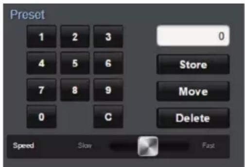
1 Save the preset information.
- Move to the pan/tilt/zoom position you want to store as a preset position, and change the corresponding setting.
2 Enter a [Preset] number button and press the [Store] button.
- Doing so stores the current pan/tilt/zoom position and the different settings to the preset number.
3 Recall the stored preset number.
- Use the preset pan/tilt speed setting bar to set the pan/tilt speed.
- Use the [Preset] number button to enter the number you want to recall, followed by pressing the [Move] button. The camera moves itself to a position that is registered as a preset position.
Memo :
- Operating other controls during a preset recall will cancel the recall.
- To delete a preset, use the number button to enter the number you want to delete, followed by pressing the [Delete] button.
You can store detailed preset information from 1 to 10, and simplified preset information from 11 to 100.
| Preset Information | Detailed | Simplified | Refer to | |
| Image Stabilizer | √ | X | ( P55 ) | |
| Exposure | √ | X | ( P55 ) | |
| AE Speed | √ | X | ( P55 ) | |
| AE Level | √ | X | ( P55 ) | |
| Slow Shutter | √ | X | ( P55 ) | |
| AGC Limit | √ | X | ( P55 ) | |
| Gain | √ | √ | ( P55 ) | |
| Night Mode | √ | X | ( P55 ) | |
| Digital Zoom | √ | X | ( P56 ) | |
| Focus Mode | √ | X | ( P56 ) | |
| AF Speed | √ | X | ( P56 ) | |
| Detail | √ | X | ( P56 ) | |
| High Sensitivity | √ | X | ( P56 ) | |
| NR | √ | X | ( P56 ) | |
| WDR | √ | X | ( P56 ) | |
| White Balance | √ | √ | ( P57 ) | |
| AWB Paint | √ | √ | ( P57 ) | |
| R/B Gain | √ | √ | ( P57 ) | |
| Color Gain | √ | X | ( P57 ) | |
| Color Phase | √ | X | ( P57 ) | |
| Shutter Position | √ | √ | - | |
| Zoom Position | √ | √ | - | |
| Focus Position | √ | √ | - | |
| IRIS Position | √ | √ | - | |
| PAN Position | √ | √ | - | |
| TILT Position | √ | √ | - | |
Memo :
- Upon recalling a preset number, the setting of the item corresponding to the number will be retained until the next preset number is recalled.
Pan/Tilt Operation
- Adjust the direction the camera is facing by pressing the [Arrows] on the Pan/Tilt Control buttons on the web browser (Live View) screen.
- Pressing the ● button restores the display area to the default position.
- Use the pan/tilt speed setting lever to set the pan/tilt speed.
Memo :
- You can set restrictions on the left and right positions.
( P57 [Pan Right Limit/Pan Left Limit] ) - You can set restrictions on the top and bottom positions.
( P58 [Tilt Up Limit/Tilt Down Limit] ) - Pan/tilt comes with a preset feature for setting the preset speed and deceleration curve.
( P57 [ Ramp Curve ] ) - You can store the preset information in the camera.
- The camera body may be captured at some pan/tilt positions.
Zoom Operation
Adjusts the angle of view.
Optical zoom ratio: 1x to 30x
Digital zoom ratio: 30x to 360x
Set digital zoom to "On"/"Off" in [Main Menu] →
[Camera Function] → [Digital Zoom].
( P56 [ Digital Zoom ] )
You can control zoom using the button on the browser screen.
During the zoom operation, the zoom bar or number will appear at the top right corner of the display screen.
(P70 [Zoom Display])

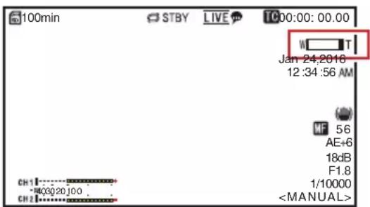
Focus Operation
Adjusting Focus Automatically
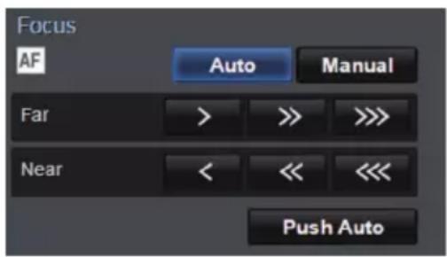
1 Press the [Auto] button under the [Focus] tab on the browser (Live View) screen.
An auto focus icon AF appears on the display screen.
One Push Auto Focus
While focus is set to manual, pressing the [Push Auto] button establishes focus automatically on the center frame.
Memo :
- One Push Auto Focus functions with emphasis on the focusing speed. This function is not suitable during recording.
Adjusting Focus Manually
1 Press the [Manual] button under the [Focus] tab on the browser (Live View) screen.
The manual focus icon MF appears on the screen.
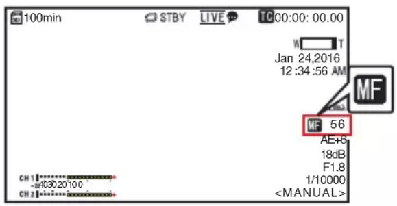
2 Press the focus control button to adjust focus.
Adjusting the Brightness
Adjust the brightness using Iris, Gain and Shutter speed according to the brightness of the object.
Adjusting the Brightness Automatically: Automatic Brightness Adjustment (AE) Mode
Iris, Gain, Shutter speed and ND filter are automatically adjusted according to the brightness of the object to maintain optimum brightness.
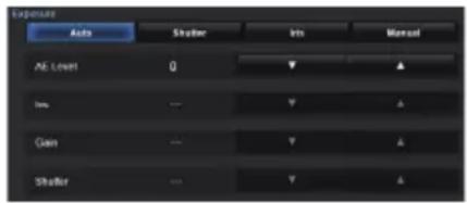
1 Set the target level (brighter/darker) to maintain optimum brightness during automatic adjustment.
- When the [Exposure] selection button is set to "Auto", "Shutter" or "Iris", you can configure the setting using the AE level control button on the View Remote screen.
▲ : Increases the brightness.
▼ : Decreases the brightness.
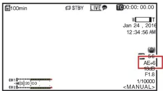
Memo :
- The convergence speed of the automatic adjustment for automatic brightness adjustment (AE) can be set in the menu. (13 P55 [ AE Level ] )
- Adjustment cannot be performed when the [Exposure] selection button is set to "Manual".
Adjusting the Brightness Manually
When the [Exposure] selection button is set to a value other than "Auto", some or all of the settings (Iris, Gain and Shutter Speed) can be manually adjusted.
- Press the [Shutter] button:
Switches to the shutter priority mode for manual setting of the shutter. Other settings are adjusted automatically. - Press the [Iris] button:
Switches to the iris priority mode for manual setting of the iris. Other settings are adjusted automatically. - Press the [Manual] button:
Switches iris, gain and shutter to manual operation.
Memo :
- When the [Exposure] selection button is set to "Manual", the [AE Level] setting is disabled.
Adjusting the Iris
Adjust the aperture of the lens iris according to the brightness of the subject.
| Auto Iris (Automatic Adjustment) Mode
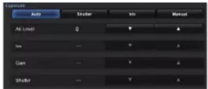
1 Set [Exposure] to "Auto" or "Shutter".
The iris is automatically adjusted according to the brightness of the object.
The lens aperture value (F-number) is not displayed in the Auto Iris mode.
Memo :
- The convergence speed of the auto iris can be set in the menu.
(P55)
Manual Iris (Manual Adjustment) Mode
The aperture value (F-number) of the lens can be set manually.
1 Set [Exposure] to "Iris" or "Manual".
The lens aperture value (F-number) is displayed.
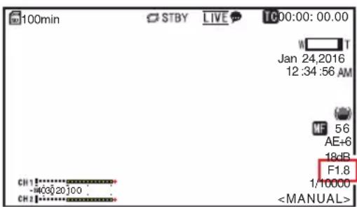
2 Press the iris adjustment button to adjust the iris manually.
▲ : Sets the iris to the Open side. ▼ : Sets the iris to the Close side.
The open F-number of the aperture varies according to the zoom position.
Wide [W] end : F1.6
Tele [T] end : F4.7
| F-number Description | |
| Decrease The | subject appears brighter.The area in focus becomes narrower, while the background is blurred to produce a soft image. |
| Increase The | subject appears darker.Background of image becomes focused as well. |
About the Iris F-number
Blurry effects due to “small aperture diffraction” may occur when the diameter of the iris becomes too small. You are therefore recommended to use the camera in an environment that does not require you to narrow the iris excessively.
Setting the Gain
This function electrically boosts the light sensitivity when there is insufficient illumination on the object. You can set the gain of the video amplifier according to the brightness of the object. Select the setting mode according to your shooting conditions.
Automatic Gain Mode (Automatic Gain Adjustment)
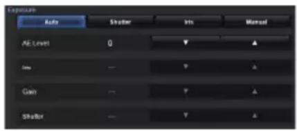
1 Set [Exposure] to "Auto".
Memo :
- The upper limit of the gain setting value during AGC operation can be set in [Main Menu] [Camera Function] [AGC Limit]. (P55 [ AGC Limit ] )
Manual Gain Mode (Manual Gain Switching)
1 Set [Exposure] to "Manual".
2 Press the gain adjustment button to adjust the gain level.
▲ : Increases the gain level. ▼ : Decreases the gain level.
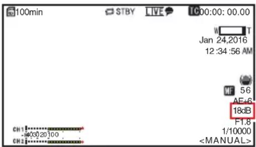
Memo :
- Increasing the sensitivity causes the screen to appear grainier.
Setting the Electronic Shutter
You can change the shutter speed (time for each shooting frame) using the electronic shutter function. Electronic shutter can be adjusted manually or automatically.
Automatic Shutter Mode (Automatic Shutter Adjustment)
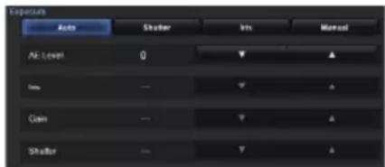
1 Set [Exposure] to "Auto" or "Iris".
- A iconappears on the left side of the shutter speed.
- Automatic Shutter mode adjusts the shutter speed automatically according to the brightness of the object.
Manual Shutter Mode (Manual Shutter Switching)
1 Set [Exposure] to "Shutter" or "Manual".
2 Press the shutter adjustment button to adjust the shutter speed.
▲ : Increases the shutter speed.
▼ : Decreases the shutter speed.
- The shutter speed appears on the screen.
- The A icon displayed on the left side of the shutter speed disappears.
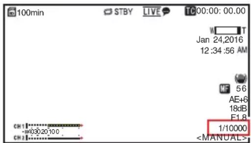
Memo :
- The settable shutter speed range differs according to the frame rate setting.
| Frame Rate 60p, 60i, 30p 50p, 50i, 25p | |
| (Upper limit) 1/10000 1/10000 | |
| 1/6000 1/6000 | |
| 1/4000 1/3500 | |
| 1/3000 1/2500 | |
| 1/2000 1/1750 | |
| 1/1500 1/1250 | |
| 1/1000 1/1000 | |
| 1/725 1/600 | |
| 1/500 1/425 | |
| 1/350 1/300 | |
| 1/250 1/215 | |
| 1/180 1/150 | |
| 1/125 1/120 | |
| 1/100 1/100 | |
| 1/90 1/75 | |
| Default values 1/60 1/50 | |
| 1/30 1/25 | |
| 1/15 1/12 | |
| (Lower limit) 1/8 1/6 | |
Adjusting the White Balance
Adjust the white balance according to the color temperature of the lighting. You can select the adjustment mode according to the shooting conditions.
As the color of the light (color temperature) varies according to the light source, it is necessary to readjust the white balance when the main light source illuminating the subject changes.
Automatic White Balance Mode (FAW: Fulltime Auto White balance)

1 Set the [White Balance] mode selection button to "FAW".
- Switches the camera to the Automatic White Balance mode. The white balance is automatically adjusted according to the color temperature of the lighting on the object.
Memo :
The FAW (Full Time Auto White Balance) mode makes automatic adjustments by sampling the color temperature of the video to obtain the most appropriate white balance level.
AWB Mode
1 Set the [White Balance] mode selection button to "AWB".
2 Press the [AWB Trigger] button.
Pressing the button automatically adjusts the white balance.
Memo :
- If there are changes in the shooting environment while the AWB mode is functioning, press the [AWB Trigger] button again to adjust the white balance.
Caution :
- Do not use highly reflective objects, such as metals. Doing so may result in improper white balance adjustment.
- The AWB function cannot provide optimum white balance with an object outside the adjustment range, for example when it contains only a single color or not enough white color.
AWB Paint Adjustment
You can fine-tune the white balance that was automatically adjusted by AWB.
1 Adjust the R and B values.
Fine-tune using the AWB paint adjustment button while referring to the AWB paint adjustment panel.
* Use the cross-shaped button (▲▼) to adjust R value and (◀) to adjust B value.
* You can also adjust the R and B values by dragging the point (O mark) on the adjustment panel.

Manual White Balance Mode (Manual Switching)
1 Set the [White Balance] mode selection button to "Manual".
R/B Gain and the corresponding value are displayed.
Example: R/B Gain R:186 B:173
2 Fine-tune using the R/B Gain adjustment button while referring to the R/B Gain adjustment panel.
* Use the cross-shaped button (▲▼) to adjust R value and (◀) to adjust B value.
* You can also adjust the R and B values by dragging the point (O mark) on the adjustment panel.
Adjusting the Camera Image
The picture quality of the camera can be set using the [Camera Process] menu.
As the adjustments are shown on the screen, you can adjust the values while checking the picture quality on the camera.
• [Detail]
• [High Sensitivity]
• [NR]
• [WDR]
- [White Balance]
• [Color Gain]
• [Color Phase]
Memo :
- For details of the respective items, see the [Camera Process] menu.
(→ P56 [Camera Process Menu])
Using the Image Stabilizer
Reduces blurcaused by camera shake in the video image.
1 Check whether the image stabilizer feature is turned ON or OFF.
If the image stabilizer icon (illus) does not appear on the screen display, the image stabilizer function is OFF.
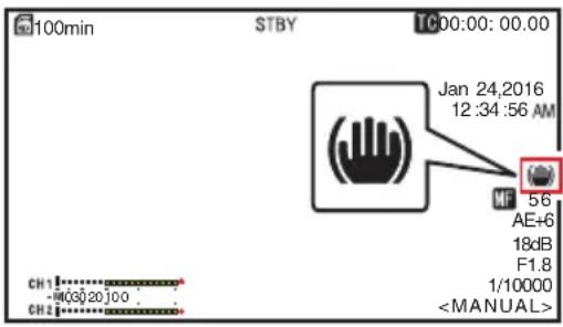
2 Set [Main Menu] → [Camera Function] → [Image Stabilizer] to "On" to reduce video image blur.
Memo :
- Correction by this feature may not be sufficient when camera shake is too strong.
- The angle of view becomes narrower when the image stabilizer function is turned on.
- The image stabilizer function is disabled when pan/tilt is operating.
Audio Recording
You can record audio from the two channels (CH1/CH2) in synchronization with video images on this camera recorder.
| Recording Audio Sound
Set [Main Menu] → [A/V Set] → [Audio Set] → [Audio] to "On" to turn on audio input to the [AUDIO IN] terminal.
Selecting the Audio Sound to Record
Select the audio sound to input to the [AUDIO IN] terminal from [Main Menu] → [A/V Set] → [Audio Set] → [Input Select].
| Setting Description | |
| [Line] Use this setting when connecting to an audio device or other equipment. The reference input level is +4 dBu. | |
| [Mic] Use this setting when connecting to a dynamic microphone. | |
| [Mic +2.5 V] Use this setting when connecting to a microphone that requires a +2.5 V power supply. |
| Setting the Audio Gain
For setting the audio input level.
( P59 [ Audio Gain ] )
Time Code and User's Bit
Time code and user's bit data are recorded with the video in this camera recorder.
During recording, the time code and user's bit are displayed on the externally connected display screen or the Live View screen.
Displaying Time Code and User's Bit
During recording, the time code and user's bit are displayed on the externally connected display screen or the Live View screen.
The display differs according to the menu settings.
1 Make a selection from [Main Menu] → [System] → [Information Display] → [TC/UB]. (P65 [TC/UB])
When “TC” or “UB” is selected, time code or user’s bit data is displayed respectively on the display screen.
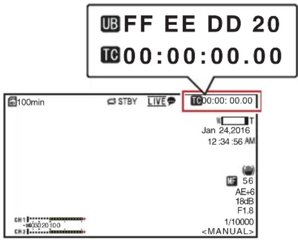
Time Code Operation Mode
Set the time code operation in [Main Menu]→[TC/UB]→[TC Generator].
(VP58 [TC Generator])
| Setting Description | |
| Free Run The time code operates in the run mode at all times regardless of the recording status. It continues to run even when the power of the camera recorder is turned off. | |
| Rec Run The time code operates in the run mode during recording. It continues to run in the order of the recorded clips as long as the microSD card is not replaced. If the microSD card is removed and recording is made on another card, time code will be recorded on the new card from where it was left off in the previous card. | |
| Regen The time code operates in the run mode during recording. When the microSD card is replaced, the last time code recorded on the card is read and recorded on a new card so that the time code continues in running order.(P48 [Setting Time Code Generator]) |
Setting Time Code Generator
| Presetting the Time Code
Time code and user's bit data generated from the internal time code generator are recorded.
This section describes how to set [TC/UB] → [TC Preset].
( P58 [ TC Preset ] )
Memo :
- When [Main Menu] [System] [Record Set]
→ [Record Format] → [Frame Rate] is set to "50p" or "50i", setting for "Drop" will be disabled. (P67 [ Frame Rate ] )
- You can configure the setting without accessing the [TC/UB] menu screen.
Required Settings Before Preset
1 Set [TC/UB] → [TC Generator] to "Rec Run" or "Free Run".
(P58 [ TC Generator ] )
• [Rec Run]:
Preset data in the time code generator operates in run mode during recording mode. Set this when recording continuous time code in connecting frames.
• [Free Run]:
Time code starts to operate in run mode from the preset time in the time code generator.
2 Select the framing mode for the time code generator (only when the frame rate setting is "60" or "30").
Set using [Main Menu] → [TC/UB] → [Drop Frame].
(▶ P58 [ Drop Frame ] )
• [Drop]:
Sets the run mode of the time code generator to drop frame mode. Use this setting when placing emphasis on the recording time.
• [Non Drop]:
Sets the run mode of the time code generator to non-drop frame mode. Use this setting when placing emphasis on the number of frames.
Memo :
Drop frame/non-drop frame mode
- When [Main Menu] [System] [Record Set] [Record Format] [Frame Rate] is set to "60p", "60i", or "30p", the actual number of frames per second is approximately 59.94 (29.97). However, the time code processing standard is "60p", "60i", or "30p" frames. To make up for the frame number discrepancy, the drop frame mode (Drop) drops the 00 frame and 01 frame every minute except for minutes that are multiples of 10. However, in the case of "60p", the 00, 01, 02 and 03 frame are dropped.
- The non-drop frame mode (Non Drop) does not drop frames and ignores the discrepancy with the actual time.
Setting Time Code
1 Select [Main Menu] → [TC/UB] → [TC Preset] and press the Set button (Set).
( P58 [ TC Preset ] )
The [TC Preset] screen appears.
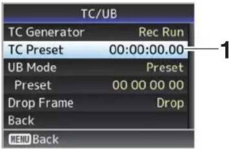
Memo :
- When [TC/UB] [TC Generator] is set to "Regen", the parameter is displayed as "Regen" and cannot be selected. (P58 [TC Generator])
2 Set the time code (hour, minute, second, frame).
Use the cross-shaped button (◀▶) to place the cursor at the item to set, then use the cross-shaped button (▲▼) to change the values.
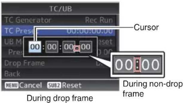
Memo :
- Pressing the [SUB 2] button resets each digit to "0" and moves the cursor to the hour digit (left).
3 Check the values and press the Set button (Set).
- The time code is set and the screen returns to [TC/UB].
4 Press the [Back] button.
Returns to the normal screen.
Recording Time Code in Continuation of the Recorded Time Code on microSD Card
This camera recorder is equipped with the time code reader.
1 Set [TC/UB] → [TC Generator] to "Regen".
- When the camera recorder enters from recording standby mode to recording mode, it reads the time code already recorded on the microSD card and records the new time code in continuation of that value. - The same data as the user's bit already recorded on the microSD card is recorded.
Memo :
- When [TC/UB] [TC Generator] is set to "Regen", the framing mode of the time code follows the settings in [TC/UB] [Drop Frame] instead of the clip settings. (P58 [ Drop Frame ] )
Setting the User's Bit
You can add the date, time or an 8-digit hexadecimal number as the user's bit to the recorded image.
| Selecting a Recording Mode
Recording date/time information to the user's bit
1 Set [Main Menu] → [TC/UB] → [UB Mode] to "Date" or "Time", and press the Set button (Set).
( P58 [ UB Mode ] )
The date or time information is recorded to the user's bit.
Memo :
- When "Date" or "Time" is set, [Preset] appears as "-" and cannot be set.
- “Time” is displayed in the 24-hour format.
| Presetting the User's Bit
Recording arbitrary information (8-digit hexadecimal) to the user's bit
1 Set [Main Menu] → [TC/UB] → [UB Mode] to "Preset", and press the Set button (Set).
( P58 [ UB Mode ] )
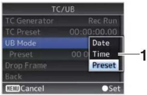
Memo :
- When [TC/UB] [TC Generator] is set to "Regen", the parameter is displayed as "Regen" and cannot be selected.
( P58 [ TC Generator ] )
2 Select [Main Menu] → [TC/UB] → "Preset" and press the Set button (Set).
The [Preset] setting screen appears.
3 Use the cross-shaped button (◀) to place the cursor at the item to set, then use the cross-shaped button (▲▼) to change the values.
Numbers between 0 and 9 or alphabets between A and F can be specified for the user's bit.
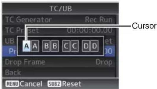
Memo :
- Pressing the [SUB 2] button resets each digit to "0" and moves the cursor to the hour digit (left).
4 Check the values and press the Set button (Set).
- The user's bit is set and the screen returns to [TC/UB].
5 Press the [Back] button.
Returns to the normal screen.
Loop Recording
During normal recording, the camera stops recording automatically when the microSD card memory is full. In this case, you can enable the Loop Recording feature for recording to continue.
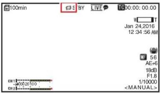
1 Set [Main Menu] → [System] → [Record Set] → [Loop Rec] to "On".
2 Set the frame rate in [Main Menu] → [System] → [Record Set] → [Frame Rate]. (P67 [Frame Rate])
Memo :
- The [Main Menu] [System] [Record Set] [4GB File Spanning(SDXC)] setting changes to "On".
( P68 [ 4GB File Spanning(SDXC) ] )
- Although recording is continuous, the videos are not processed as a single clip but as a new file that contains multiple clips.
- The clips are automatically split while recording is in progress.
- When the remaining space on the card runs out, files will be deleted automatically starting from the oldest data and recording will continue without disruption.
- During Loop Recording, the remaining level of the media displayed is the maximum recording time of the microSD card.
• However, the maximum recording time of the card may be shorter than the remaining level that is displayed.
- You are recommended to format the card before using.
Basic Operations in Menu Screen
- The menu screen can be displayed on the web browser (View Remote) screen or the screen of the externally connected monitor.
- Various settings for shooting can be configured on the menu screen.
Displaying the Menu Screen
1 Press the □ (Live View) button in the [Live View/setting screen selection] tab on the web browser (View Remote) screen.
• The Live View screen is displayed.
2 Press the [MENU] button in the [camera/menu operation screen selection] tab on the View Remote screen.
- The display switches to the menu operation screen.
3 Press the [MENU] button on the menu operation screen.
- The menu screen is displayed.
Memo :
- When [Back] appears in the menu, selecting [Back] returns the display to the menu screen that is one level higher in the hierarchy.
Display and Description of the Menu Screen
Selecting Menu Items
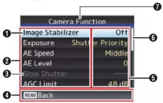
① Cursor
Indicates the selected item. Use the cross-shaped button (▲▼) to move the cursor
② Menu Item
- Displays the names of the menu item and sub-menu.
- Menu items with [...] after them indicates that there is a sub-menu to access.
③ Fixed Item
Items that cannot be changed are displayed in gray and cannot be selected.
④ Operation Guide
Guide for the current operation buttons.
⑤ Setting Value
Setting values for the menu items.
For menus with sub-menus, values are not displayed.
⑥ Scroll Bar
Indicates the scroll position.
⑦ Menu Title
Title of the currently displayed menu.
Changing Setting Values
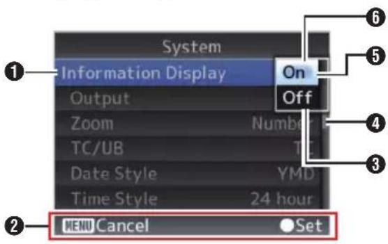
① Menu Item to Change
Menu item to be changed.
A list of setting values ⑥ appears in a pop-up.
② Operation Guide
Guide for the current operation buttons.
③ Setting Values Before Change Setting values before changing. The background of the item is displayed in blue.
④ Scroll Bar
Indicates the scroll position.
⑤ Cursor
Indicates the selected item. Use the cross-shaped button (▲▼) to move the cursor
6 List of Setting Values
- A pop-up displaying a list of setting values for selection.
- The height of the pop-up depends on the number of settings available.
| Text Input with Software Keyboard
Use the software keyboard to enter the [Setup File] subname, [Clip Name Prefix], and the settings under [Network] [Settings]. Use the software keyboard to enter the [Setup File] subname and [Clip Name Prefix].
Entering a subname
(→ P80 [ Planning Metadata ] )
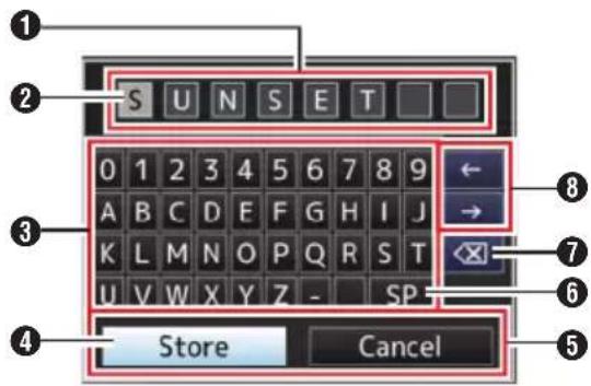
Entering the [Clip Name Prefix]
( P68 [ Clip Name Prefix ] )
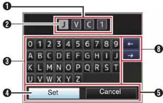
Settings under [Network] → [Settings]
The keyboard displayed varies according to the settings.
( P60 [Network Menu] )
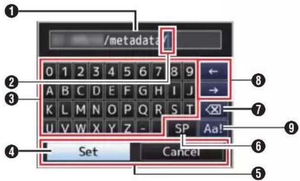
① Character Entry Field
- Field for entering the title. - You can enter up to 8 characters for the [Setup File] subname or up to 4 characters for the [Clip Name Prefix].
② Character Cursor
Select a character using the key cursor ④, and press the Set button (Set) to input the selected character at the position of the character cursor. The character cursor moves to the next position on the right each time a character is input. The cursor can be moved using the arrow keys ⑧.
③ Character Keys
Use the cross-shaped button (▲▼◀) to move the key cursor ④ to the character you want to enter.
④ Key Cursor
Indicates the currently selected character or item. Use the cross-shaped button (▲▼◀▶) to move the cursor.
⑤ Confirmation Buttons
- Select [Set]/[Store] and press the Set button (Set) to confirm the title. - Select [Cancel] and press the Set button (Set) to abort character input and return to the previous screen.
⑥ [SP] Space Key
Select [SP] and press the Set button (Set) to enter a space at the current position of the character cursor ②.
⑦ [×] Backspace Key
Select [✗] and press the Set button (Set) to delete the character to the left of the character cursor ②.
⑧ Arrow Keys
Moves the position of the character cursor ②.
⑨ Character Switch Button
Switches the character buttons ③ to the upper case, lower case, and symbols.
Menu Screen Hierarchical Chart
[Main Menu...] (P 54)
[Camera Function...] (P 55)
- [Image Stabilizer] ..... (P 55)
- [Exposure] ...... (P 55)
- [AE Speed] ...... (P 55)
- [AE Level] ...... (P 55)
- [Slow Shutter] ..... (P 55)
- [AGC Limit] (P 55)
- [Gain] ..... (P 55)
- [Shutter] ...... (P 55)
- [Iris (Wide)] ...... (P 55)
- [Night Mode] ...... (P 55)
[Defog] (P 55)
[Digital Zoom] (P 56)
- [Focus Mode] ...... (P 56)
- [AF Speed] ..... (P 56)
^L [Bars] ..... (P 56)
[Camera Process...] (P 56)
[Detail] (P 56)
- [High Sensitivity] ..... (P 56)
[NR] (P 56)
[ WDR ] ...... ( P 56 )
[White Balance...] (P 57)
[AWB Paint].... (P 57) [R/B Gain].... (P 57)
- [Color Gain] ..... (P 57)
[Color Phase] ..... (P 57)
L [Reset Process Settings] ...... (P 57)
[Pan/Tilt...] (P 57)
- [Pan/Tilt Preset Speed] ..... (P 57)
- [Ramp Curve] ..... (P 57)
- [Speed With Zoom] ...... (P 57)
[Freeze during Preset] ..... (P 57)
[Pan Right Limit] (P 57)
L [Pan Left Limit] ...... (P 57)
[ Tilt Up Limit ] ...... ( P 58 )
L [Tilt Down Limit] ..... (P 58)
[TC/UB...] (P 58)
- [TC Generator] ..... (P 58)
- [TC Preset] ..... (P 58)
- [UB Mode] ..... (P 58)
[Drop Frame] (P 58)
[A/V Set...] (P 59)
- [Video Set...] ...... (P 59)
L [Audio Set...] ..... (P 59)
[Network] (P 60)
- [Connection Setup...] ..... (P 60)
- [Web...] ..... (P 60)
- [Live Streaming Set...] ..... (P 61)
- [Clip Server...] ..... (P 63)
- [Metadata Server...] ..... (P 64)
- [Import Metadata] ...... (P 64)
[Reset Network Settings] ..... (P 64)
[System...] (P 65)
- [System Mode] ...... (P 65)
- [Record Set...] (P 65)
- [Media] ..... (P 65)
- [Information Display] ...... (P 65)
- [Date Style] ...... (P 65)
- [Time Style] ...... (P 66)
- [IR ID] ...... (P 66)
- [Tally Lamp] ...... (P 66)
- [Language] ..... (P 66)
- [Reset All] ...... (P 66)
- [Date/Time] ...... (P 66)
- [Time Zone] (P 66)
- [Install Position] ...... (P 67)
[System Information] ..... (P 67)
Memo :
- Some menus cannot be set depending on the operating mode or status of the camera recorder. These items are displayed in gray, and they cannot be selected.
- Setting value with the ● mark is the factory default.
Camera Function Menu
Menu screen for specifying operation settings during shooting.
This item can only be selected in the Camera mode.
Image Stabilizer
For setting whether to enable the image stabilizer.
[Setting Values: On, ●Off]
Exposure
Select method for controlling the brightness.
- Auto:
Gain/Shutter/Iris are adjusted automatically. - Shutter Priority:
Gain and Iris are adjusted automatically with priority given to the Shutter setting. Shutter speed setting can be adjusted according to the [Shutter] menu setting.
- Iris Priority: Gain and Shutter are adjusted automatically with priority given to the Iris setting. Iris setting can be adjusted according to the [Iris (Wide)] menu setting.
- Manual: Gain/Shutter/Iris operate according to the menu setting.
[Setting Values: ●Auto, Shutter Priority, Iris Priority, Manual]
AE Speed
For setting the convergence speed during AE (Auto Exposure).
[Setting Values: Fast, ●Middle, Slow]
AE Level
For setting the convergence level during AE (Auto Exposure).
[Setting Values: -6 to +6 (●0)]
Slow Shutter
Setting to “On” enables slow shutter automatically to increase the sensitivity level when the brightness of the subject decreases.
[Setting Values: ●On, Off]
Memo :
- This item is available only when [Exposure] is set to "Auto".
- When the subject is dark, the shutter speed slows down to 1/8 (1/6).
AGC Limit
For setting the maximum gain value of "AGC", which electrically boosts the sensitivity level according to the brightness automatically.
[Setting Values: ●48dB, 42dB, 36dB, 30dB, 24dB, 21dB, 18dB, 15dB, 12dB, 9dB]
Gain
For setting the gain value.
[Setting Values: 48dB, 42dB, 36dB, 30dB, 24dB, 21dB, 18dB, 15dB, 12dB, 9dB, 6dB, 3dB, ●0dB]
Shutter
For specifying shutter-related settings.
- When [Main Menu] [System] [Record Set]
→ [Frame Rate] is set to “60p”, “60i” or “30p”: [Setting values: 1/8, 1/15, 1/30, ●1/60, 1/90, 1/100, 1/125, 1/180, 1/250, 1/350, 1/500, 1/725, 1/1000, 1/1500, 1/2000, 1/3000, 1/4000, 1/6000, 1/10000] - When [Main Menu] [System] [Record Set]
→ [Frame Rate] is set to “50p”, “50i” or “25p”: [Setting values: 1/6, 1/12, 1/25, ●1/50, 1/75, 1/100, 1/120, 1/150, 1/215, 1/300, 1/425, 1/600, 1/1000, 1/1250, 1/1750, 1/2500, 1/3500, 1/6000, 1/10000]
Iris (Wide)
For setting the iris value (F number). The value here indicates the F number at the wide-angle end of the zoom position. The F number changes with the zoom position.
Setting to "CLOSE" closes the iris completely.
[Setting Values: F1.6, F2.0, F2.4, F2.8, F3.4, ●F4.0, F4.8, F5.6, F6.8, F8.0, F9.6, F11, F14, CLOSE]
Night Mode
Setting to "On" increases the sensitivity level under low-light conditions.
[Setting Values: On, ●Off]
Defog
When the contrast level decreases such as when the subject is obscured by fog in the surrounding environment, enabling this mode allows the subject to appear clearer.
[Setting Values: High, Middle, Low, ●Off]
Digital Zoom
For setting whether to enable the digital zoom function.
- Off: Enables only the optical zoom (1x to 30x).
- On: Enables the dynamic zoom (30x to 360x) in addition to the optical zoom.
[Setting Values: ●Off, On]
Focus Mode
For setting the focusing operation.
[Setting Values: ●Auto, Manual]
AF Speed
For setting the AF operation speed.
[Setting Values: ●Fast, Slow]
Bars
For setting whether to output color bars.
[Setting Values: On, ●Off]
Memo :
- The audio test signals (1 kHz) can be output simultaneously with the color bar output.
( P59 [ Test Tone ] )
Camera Process Menu
Menu screen for adjusting the quality of camera images.
Detail
For adjusting the contour (detail) enhancement level.
Increasing the value increases the sharpness of the contour.
[Setting Values: Off, -5 to +5 (●0)]
High Sensitivity
Setting to "On" increases the maximum gain level for a bright screen even in a dimly-lit environment. [Setting Values: On, ●Off]
Memo :
- Note that increasing the gain level may cause noise to become more noticeable.
NR
Decreases noise in the image.
• High:
Applies a strong amount of noise reduction.
- Low: Applies a weak amount of noise reduction.
- Off: Disables noise reduction.
[Setting Values: High, ●Low, Off]
WDR
For setting the WDR (Wide Dynamic Range) function.
When shooting object with wide dynamic range due to backlight conditions, this function compresses the dynamic range while maintaining image contrast through providing gradation compensation to the input video signals.
• Strong: Enhances the effect of gradation compensation for object with wide dynamic range due to outdoor or strong backlight conditions.
- Natural: Normal setting for wide dynamic range.
- Weak: Reduces the effect of gradation compensation compared to the normal setting.
- Off: Sets the wide dynamic range function to "Off".
[Setting Values: Strong, Natural, Weak, ●Off]
White Balance
For setting the white balance mode.
- FAW: Switches the camera to the Automatic White Balance mode. The white balance is automatically adjusted according to the color temperature of the lighting on the object.
- AWB: Pressing the[AWB Trigger] button automatically adjusts the white balance.
- 5600K: Sets white balance to a color temperature of 5600K.
- 3200K: Sets white balance to a color temperature of 3200K.
- Manual: For adjusting the white balance manually. Setting Values: ●FAW, AWB, 5600K, 3200K, Manual]
* For details, refer to “[Adjusting the White Balance] (P 45)”.
→ AWB Paint
For adjusting the R (red) and B (blue) components during AWB.
- Increase the number: Strengthens the red/blue.
- Decrease the number: Weakens the red/blue.
[Setting values: R: -32 to +32 (●0); B: -32 to +32 (●0)]
→ R/B Gain
For setting the R Gain and B Gain values respectively.
[Setting values: R: 0 to 255; B: 0 to 255]
Color Gain
For adjusting the video signal color level. Increasing the value deepens the color.
[Setting Values: Off, -4 to +10 (●0)]
Memo :
- Images are displayed in black-and-white when this is set to "Off".
Color Phase
For setting the color phase.
[Setting Values: -5 to +5 (●0)]
Reset Process Settings
Restores all items in the [Camera Process] menu to their default settings.
Pan/Tilt Menu
Pan/Tilt Preset Speed
For setting the speed for moving to the pan/tilt position configured in the Preset mode.
[Setting Values: 1 to 30]
Ramp Curve
For setting how you want the movement to slow down when moving to the position configured in the Preset mode.
- Linear: Stops after reducing speed at a fixed rate.
- Ease: Reduces speed gradually before coming to a smooth stop.
[Setting Values: Linear, ●Ease]
Speed With Zoom
Setting to “On” reduces the speed of pan/tilt movement further as the camera zooms toward the Tele end.
[Setting Values: ●On, Off]
Freeze during Preset
Setting to “On” displays the video image before movement starts as a still image during the interval after preset starts until the camera has reached the registered position.
[Setting Values: On, ●Off]
Memo :
- This feature can be enabled for preset pan/tilt/zoom operations.
Pan Right Limit/Pan Left Limit
Sets a limit on the horizontal (left/right) range of the pan operation. Selecting Set sets the current position as the pan limit. Movement beyond this point is not allowed.
Selecting Release releases the restriction.
[Setting Values: Set, ●Release]
Memo :
- The operation speed varies depending on whether an AC adapter or a PoE+ power supply is used.
When an AC adapter is used : Maximum 480°/S
During PoE+ power supply : Maximum 400°/S
Tilt Up Limit/Tilt Down Limit
Sets a limit on the vertical (up/down) range of the tilt operation. Selecting Set sets the current position as the tilt limit. Movement beyond this point is not allowed.
Selecting Release releases the restriction.
[Setting Values: Set, ●Release]
Memo :
- The operation speed varies depending on whether an AC adapter or a PoE+ power supply is used.
When an AC adapter is used : Maximum 300°/S
During PoE+ power supply : Maximum 200°/S
TC/UB Menu
Menu screen for setting time code and user's bit. This item cannot be selected while recording is in progress.
TC Generator
For setting the operation of the time code.
- Free Run:
The time code operates in the run mode at all times regardless of the recording status. It continues to run even when the power of the camera recorder is turned off.
- Rec Run:
The time code operates in the run mode during recording. It continues to run in the order of the recorded clips as long as the microSD card is not replaced. If the microSD card is removed and recording is made on another card, time code will be recorded on the new card from where it was left off in the previous card.
- Regen:
The time code operates in the run mode during recording. When the microSD card is replaced, the last time code recorded on the card is read and recorded on a new card so that the time code continues in running order.
[Setting Values: Free Run, ●Rec Run, Regen]
TC Preset
For setting the time code (hour, minute, second, frame).
Display : Drop setting 02:02:25.20
: Non Drop setting 02:02:25:20
Memo :
- When [TC/UB] [TC Generator] is set to "Regen", the parameter is displayed as "Regen" and cannot be selected.
UB Mode
For setting the recording mode of the user's bit.
- Date: Records the date.
• Time: Records the time.
- Preset: Records according to the preset setting. (P50 [Setting the User's Bit])
[Setting Values: Date, Time, ●Preset]
Memo :
- If UB Mode is set to "Time", the user's bit operates in the 24-hour format even if the LCD display on the web browser (Live View) screen or screen of the externally connected monitor is in the 12-hour format.
→ Preset
For setting the user's bit. (Digit by digit)
Display : AB CD EF 01 ( P50 [Presetting the User's Bit] )
Memo :
- When [UB Mode] is set to "Date" or "Time", this item appears as "---" and preset is disabled.
- When [TC/UB] [TC Generator] is set to "Regen", the parameter is displayed as "Regen" and cannot be selected.
Drop Frame
For setting the framing mode of the time code generator.
- Non Drop: Internal time code generator works in the non-drop-frame mode. Use this setting when placing emphasis on the number of frames.
- Drop: Internal time code generator works in the drop-frame mode. Use this setting when placing emphasis on the recording time.
[Setting Values: Non Drop, ●Drop]
Memo :
- This item can be set only when [Main Menu] [System] [Record Set] [Record Format] [Frame Rate] is set to "60p", "30p", or "60i".
When [Frame Rate] is “50p”, “25p”, or “50i”, this item appears as “---” and cannot be selected. (P67 [ Frame Rate ] )
A/V Set Menu
Menu screen for video output and audio.
Video Set...
For specifying video output-related settings. (Ⅲ P59 [Video Set Item])
Audio Set...
For specifying audio-related settings. ( P59 [Audio Set Item] )
Video Set Item
HDMI/SDI Out
For setting the terminal to output the video. [Setting Values: ●HDMI+SDI, SDI, HDMI]
→ Resolution
For selecting the resolution of video output from the [HDMI] terminal or [SDI OUT] terminal according to the monitor to be connected.
- When SDI or HDMI+SDI is selected 1080p mode: 1080/60p, 1080/50p, 1080/60i, 1080/50i, 1080/30p, 1080/25p 720p mode: 720/60p, 720/50p
- For HDMI 1080p mode: Auto, 1080/60p, 1080/50p, 1080/60i, 1080/50i, 1080/30p, 1080/25p 720p mode: Auto, 720/60p, 720/50p
Memo :
- The selectable options vary according to the setting in [System] [System Mode].
• Cross conversion output is not possible.
HDMI Color
- For setting the color format of HDMI signals.
- This item is selectable when [HDMI/SDI Out] is set to "HDMI" or "HDMI+SDI".
[Setting Values: RGB, ●Auto]
→ HDMI Enhance
- For setting the color range of HDMI signals. When connecting to a PC monitor, set this to "On".
- This item is selectable when [HDMI/SDI Out] is set to "HDMI" or "HDMI+SDI".
[Setting Values: On, ●Off]
→ HDMI TC
For setting whether to superimpose time code to the [HDMI] terminal.
[Setting Values: On, ●Off]
Memo :
- When [Main Menu] [A/V Set] [Video Set] [HDMI/SDI Out] is set to "SDI", [HDMI TC] is fixed at "Off" and cannot be selected.
- Set to "Off" if connecting to a device that does not support HDMI TC.
3G-SDI Mapping
For setting the 3G-SDI mapping structure. [Setting Values: ●Level A, Level B]
Memo :
- Available when [Main Menu] [System] [Resolution] is set to "1080/60p" or "1080/50p".
- When [HDMI/SDI Out] is set to "HDMI", this item appears as “---” and cannot be selected.
Audio Set Item
Audio
For setting whether to input audio sound. [Setting Values: On, ●Off]
Input Mode
For setting the audio input mode.
[Setting Values: ●Unbalanced Stereo, Balanced Mono]
Input Select
Select the audio sound to input to the [AUDIO IN] terminal. [Setting Values: ●Line, Mic, Mic +2.5 V]
Audio Gain
For setting the audio input level. [Setting Values: ●High, Low]
Equalizer
For setting the sound quality. [Setting Values: Speech Enhancement, Low Cut, ●Off]
Test Tone
For specifying whether to output the audio test signals (1 kHz) during color bar output. [Setting Values: On, ●Off]
Network Menu
For specifying network-related settings.
The display of the software keyboard for input varies according to the item you are setting.
(▶ P53 [Text Input with Software Keyboard])
Connection Setup
For configuring the network connection settings.
You can Load, Store, and Delete the settings specified on the [USB Wizard] screen.
Memo :
- Configure a different network address (network segment) for the LAN terminal and USB terminal.
→ LAN Wizard
Displays a [Wizard] screen for connecting to the network via the [LAN] terminal.
Follow the instructions on the screen.
→ USB Wizard
Displays a [USB Wizard] screen for connecting to the network via the [USB] terminal.
Follow the instructions on the screen.
Load
Loads the settings on the [USB Wizard] screen.
( P95 [Reading the Connection Settings File] )
→ Store
Saves the settings on the [USB Wizard] screen.
( P94 [Saving the Connection Settings File] )
→ Delete
Deletes the saved settings.
( P95 [Deleting Connection Settings] )
→ Default Gateway
For selecting whether to use the default gateway setting for the LAN or USB terminal. Select the terminal that is connected to the router for external network access.
[Setting Values: ●LAN, USB]
→ FTP Proxy
For setting the FTP proxy.
■ Type:
Select the type of FTP proxy.
[Setting values: HTTP, ●No Proxy]
Server:
Set the FTP proxy server name.
Memo :
- Enter the name using the onscreen keyboard.
- You can enter characters not more than 127 bytes using single-byte alphanumeric characters (a to z, 0 to 9), single-byte hyphen (“-”) or dot (“.”).
- When [Type] is set to "No Proxy", changes cannot be made.
Port:
Set the FTP proxy port number.
Memo :
- Enter the name using the onscreen keyboard.
- Enter an integer between 1 and 65535.
→ APN
For setting the APN (Access Point Name) for network connection using a cellular adapter.
* This item is grayed out and cannot be selected if APN cannot be set for the adapter attached.
Caution :
- The APN setting is written into the cellular adapter, not this camera recorder. Setting a wrong APN may result in communication failure or expensive bills from the telecommunications company. Set the APN correctly. (☐ P78 [Connecting via Cellular Adapter (USB)])
Web
For setting the functions that make use of the web browser.
→ Web Access
To access via a web browser, set to "On".
[Setting Values: ●On, Off]
→ Camera Name
For setting the name to be displayed on the web browser. Enter not more than 8 characters using the software keyboard.
(Default value: PZ100)
→ Login Name (Fixed)
The login name is "jvc". It cannot be changed.
Login Password
Changes the password for accessing via a web browser.
The current password is displayed. Enter a new password directly.
Enter not more than 31 characters using the software keyboard.
- When RM-LP100 is in use, change the password setting for RM-LP100 at the same time.
→ Resolution
For setting the resolution on the Live View screen.
[Setting values: ●640x360, 320x180]
Live Streaming Set
For specifying settings for distributing live video images.
Live Streaming
Starts live distribution when "On" is selected.
[Setting Values: On, ●Off]
Memo :
- “On” cannot be selected if streaming is not possible with the selected resolution, frame rate and bitrate combination.
- “On” cannot be selected if network connection is not established.
- “On” cannot be selected when FTP is running.
- Switches automatically to "Off" in the VIDEO OFF mode.
→ Interface
For selecting the terminal for live streaming.
[Setting Values: ●LAN, USB]
→ Server
For selecting the server for live streaming. [Setting Values: ●Server1, Server2, Server3, Server4]
Memo :
- The setting cannot be changed during live streaming (Live Streaming set to "On").
→ Streaming Server
For setting the server for live streaming.
Memo :
- The setting cannot be changed during live streaming (Live Streaming set to "On").
→ Server1/Server2/Server3/Server4
* The name that is set in [Alias] is displayed individually.
Alias
For setting a name to distinguish the settings of this camera. The name set in this item will be displayed in the Streaming Server options.
* The default value is "Server1/Server2/Server3/Server4".
* You can enter up to 31 characters and ASCII characters.
Type
For setting the system to transfer videos for distribution.
[Setting Values: ●MPEG2-TS/UDP, MPEG2-TS/RTP, RTSP/RTP, ZIXI, RTMP]
Memo :
- Use reception devices that are compatible with the respective transfer systems.
- To use the "ZIXI" setting, a dedicated server is needed separately.
- The following items that can be set vary depending on the setting of this item.
■ Destination Address
For setting details such as the host name and the IP address of the live distribution destination.
* Enter not more than 127 characters using single-byte alphanumeric characters (a to z, 0 to 9), single-byte hyphen [-], or dot [.].
■ Destination URL
For entering the URL of the live distribution destination beginning with "rtmp://".
There is no default value (blank).
* You can enter up to 191 characters and ASCII characters.
■ Destination Port
Enter the network port number of the live distribution destination using an integer between 1 and 65535.
When [Type] is set to "MPEG2-TS/UDP" or "MPEG2-TS/RTP", the default value is "6504". If "ZIXI" is set, the default value is "2088".
Memo :
- When [Type] is set to "MPEG2-TS/RTP", only even numbers from 2 to 65530 can be specified for the port number.
- When [Type] is set to “MPEG2-TS/RTP” and [SMPTE 2022-1 FEC] is set to “On”, N+2 and N +4 port numbers are also used in addition to the specified port number (N).
Stream ID
For setting the registered stream ID of the live distribution destination.
The default value varies with the product model.
* Enter not more than 63 characters.
Stream Key
Enter the stream key specified at the live transmission destination.
There is no default value (blank).
* Enter not more than 63 characters.
Password
For setting the password.
There is no default value (blank).
* Enter not more than 127 characters. Enter not more than 31 characters for RTSP/RTP setting.
Latency
For setting the latency mode.
[Setting values: Minimun(ZIXI Off), ●Low, Medium, High]
■ Adaptive Bit Rate
If "On" is selected, the bit rate setting value of live streaming is set to maximum limit, and the bit rate is changed automatically according to changes in the network bandwidth.
[Setting Values: On, ●Off]
Memo :
- [Adaptive Bit Rate] is selectable when [Type] is set to "ZIXI" and [Latency] is set to a value other than "Minimun(ZIXI Off)".
* The bit rate is displayed on the status screen only when "On" is set.
■ SMPTE 2022-1 FEC
Set to "On" to use FEC (Forward Error Correction).
A transmission system that recovers the missing packets in the decoding process without having to retransmit the missing packets.
[Setting Values: On, ●Off]
* The decoder must be compatible with SMPTE 2022-1.
■ FEC Matrix
For setting the amount of FEC (Forward Error Correction) overhead for configuring SMPTE2022-1.
(P100 [Setting the FEC Matrix])
Memo :
- This item is selectable only when [SMPTE 2022-1 FEC] is set to "On".
→ Resolution
For setting the resolution of the video image during live distribution.
The selectable options vary according to the System Mode setting.
| System Mode | Setting Value(●: default value) |
| 1080/60 | ●1920x1080 |
| 1080/50 | 1280x720 |
| 640x360 | |
| 720/60 | ●1280x720 |
| 720/50 | 640x360 |
→ Frame Rate
For setting the frame rate of the video image during live distribution.
The selectable options vary according to the settings in [System Mode] and [Resolution].
| System Mode R | Resolution Setting | Value |
| 1080/60 | 1920x1080 | 60p, 60i, 30p |
| 1080/50 50p, 50i, | 1280x720 | |
| 640x360 | ||
| 720/60 1280x720 | 640x360 | 60p, 30p |
| 720/50 50p, 25p |
Memo :
- The setting cannot be changed during live streaming (Live Streaming set to "On").
→ Bit Rate
Forsetting the bitrate of the video image during live distribution.
The selectable options vary according to the settings in [System Mode], [Resolution] and [Frame Rate].
For details on the settings, please refer to [[Live Streaming Set] Combinations that Support Distribution] (P 98).
Memo :
- The setting cannot be changed during live streaming (Live Streaming set to "On").
- Depending on the type of network adapter used and the connection, the images and audio sound during live streaming can be choppy.
Clip Server
For setting the server and directory for uploading recorded clips in the microSD card to the FTP server.
→ Clip-FTP1 to Clip-FTP4 (The name specified in the respective [Alias] items is displayed)
Alias
For setting a name to distinguish the settings of this camera recorder.
The nameset in this item will appear on the [FTP Upload] action screen of the clip list display.
* Enter not more than 31 characters.
Protocol
For setting the protocol of the FTP server to be connected.
- FTP: Protocol that does not encrypt the incoming and outgoing data.
- SFTP: Protocol that encrypts incoming and outgoing data using SSH.
- FTPS: Protocol that encrypts incoming and outgoing data using SSL or TLS. It uses an implicit mode (starts encrypted communication once connection starts).
- FTPES: Protocol that encrypts incoming and outgoing data using SSL or TLS. It uses an explicit mode (starts encrypted communication after permission is granted).
- ZIXI: Select this item when transferring files via the ZIXI server.
[Setting Values: ●FTP, SFTP, FTPS, FTPES, ZIXI]
Memo :
- To use the "ZIXI" setting, a dedicated server is needed separately.
- If "ZIXI" is set, the resume function is enabled.
Server
For setting the server name (“mystation.com”, etc.) or the IP address (“192.168.0.1”, etc.) of the FTP server.
* Enter not more than 127 characters using single-byte alphanumeric characters (a to z, 0 to 9), single-byte hyphen [-], or dot [.].
Port
Enter the FTP server port number to use using an integer between 1 and 65535.
The default value varies with the Protocol setting.
(FTP: 21, SFTP: 22, FTPS: 990, FTPES: 21, ZIXI: 2088)
Dir. Path
Enter the path name for the directory to upload to (“/pub”, “/home/user”, etc.)
* Enter not more than 127 characters.
Username
Enter the user name for connecting to the FTP server.
* Enter not more than 31 characters.
■ Password
Enter the password for connecting to the FTP server.
* Enter not more than 31 characters. When [Protocol] is set to "ZIXI", enter not more than 127 characters.
■ PASV Mode
For setting whether to set the communication mode used for file transfer to the passive mode. Set to "On" if the camera is inside a firewall, and a connection from the FTP server to the camera cannot be established.
[Setting Values: On, ●Off]
Memo :
- When [Protocol] is set to "SFTP" or "ZIXI", this item appears as "--" and cannot be selected.
Metadata Server
For registering the FTP server for importing the metadata and the path of the file to be imported. Up to 4 settings can be registered.
→ Meta-FTP1 to Meta-FTP4 (The name specified in the respective [Alias] items is displayed)
Alias
For setting a name to distinguish the settings of this camera recorder.
The name set in this item will be displayed in the [Import Metadata] options.
* Enter not more than 31 characters.
Protocol
For setting the protocol of the FTP server to be connected.
- FTP:
Protocol that does not encrypt the incoming and outgoing data.
- SFTP:
Protocol that encrypts incoming and outgoing data using SSH.
- FTPS:
Protocol that encrypts incoming and outgoing data using SSL or TLS. It uses an implicit mode (starts encrypted communication once connection starts).
- FTPES:
Protocol that encrypts incoming and outgoing data using SSL or TLS. It uses an explicit mode (starts encrypted communication after permission is granted).
[Setting Values: ●FTP, SFTP, FTPS, FTPES]
Server
For setting the server name ("mystation.com", etc.) or the IP address ("192.168.0.1", etc.) of the FTP server.
* Enter not more than 127 characters using single-byte alphanumeric characters (a to z, 0 to 9), single-byte hyphen [-], or dot [.].
Port
Enter the FTP server port number to use using an integer between 1 and 65535.
The default value varies with the Protocol setting.
(FTP: 21, SFTP: 22, FTPS: 990, FTPES: 21)
■ File Path
Enter the path name for the metadata file (“/pub/meta.xml”, “/home/user/meta2.xml”, etc.)
* Enter not more than 127 characters.
Username
Enter the user name for connecting to the FTP server.
* Enter not more than 31 characters.
Password
Enter the password for connecting to the FTP server.
* Enter not more than 31 characters.
■ PASV Mode
For setting whether to set the communication mode used for file transfer to the passive mode. Set to “On” if the camera is inside a firewall, and a connection from the FTP server to the camera cannot be established.
[Setting Values: On, ●Off]
Memo :
- When [Protocol] is set to "SFTP", this item appears as "--" and cannot be selected.
→ Import Metadata
- For importing metadata from the FTP server.
- Metadata loaded by the setup files will be deleted.
Memo :
- This option is not available when [Network] is set to "Off".
Reset Network Settings
Restores all items in the [Network] menu to their default settings.
System Menu
This menu screen allows system-related settings. For specifying recording settings, formatting and restoring of microSD card, tally lamp setting, date/time, time zone, and other settings. It can also be used to reset the menu settings to their default values.
System Mode
For selecting the resolution and frame rate.
[Setting Values: 1080/60, 1080/50, 720/60, 720/50]
Memo :
- The settings cannot be changed during recording or streaming.
Record Set...
For specifying recorded video-related settings.
( P67 [Record Set Item] )
Media
→ Format Media
For formatting (initializing) an microSD card. Select [Format] from [Cancel]/[Format], and press the Set button (Set) to start formatting (initializing). (☐ P28 [Formatting (Initializing) microSD Cards])
→ Restore Media
For restoring a microSD card. Press the Set button (Set) to start restoring the microSD card. ( P28 [Restoring the microSD Card] )
Memo :
- This item appears only when a microSD card has been inserted. However, it is not selectable when recording in the Camera mode.
Information Display
For setting whether to display information such as the camera status, microSD card information and time code over the video image on the screen of the externally connected monitor or the web browser (Live View) screen.
[Setting Values: ●]On, Off]
→ Output
For setting where to output the display when [Information Display] is set to "On".
• All:
Displays information on all screens (web browser (Live View) screen and video/live streaming screen).
- Video/Live Streaming: Displays information on the video/live streaming screen.
- Web:
Displays information on the web browser (Live View) screen.
[Setting Values: All, Video/Live Streaming, ●Web]
→ Zoom
For setting the way to display the zoom position when [Information Display] is set to "On".
- Number:
Displays the zoom position in numbers (0-99). - Bar:
Displays the zoom position in a bar.
[Setting Values: Number, ●Bar]
TC/UB
For setting whether to display the time code (TC) or user's bit (UB) on the web browser (Live View) screen or screen of an externally connected monitor when [Information Display] is set to "On".
[Setting Values: UB, ●TC]
Date Style
For setting the sequence for displaying the date on the web browser (Live View) screen or screen of an externally connected monitor as well as the date of the time stamp recording when [Information Display] is set to "On".
Display examples of the setting values are as follows.
• DMY2: 30 Jun 2016
• DMY1: 30-06-2016
• MDY2: Jun 30, 2016
• MDY1: 06-30-2016
• YMD: 2016-06-30
[Setting Values: DMY2, DMY1, MDY1, MDY2, YMD]
(Default values: MDY2 (U model), DMY1 (E model))
Time Style
For setting the time display on the web browser (Live View) screen and externally connected monitor screen as well as that for time stamp recording.
[Setting Values: 24hour, 12hour]
(Default values: 12hour (U model), 24hour (E model))
IR ID
For selecting a camera ID when operating via an infrared remote control unit.
[Setting Values: CAM3, CAM2, ●CAM1]
Tally Lamp
For setting whether to light up the tally lamp during external control, recording or live streaming.
- External:
Lights up during external control.
• Rec/Live Streaming:
Lights up during recording or live streaming.
• Live Streaming:
Lights up during live streaming. Does not light up during recording.
- Rec:
Lights up during recording.
- Off:
Turns off the indicator.
[Setting Values: ●External, Rec/Live Streaming, Live Streaming, Rec, Off]
Memo :
Depending on the setting, the lamp might appear blinking such as when there is insufficient space on the microSD card during recording or when a communication error occurs during live streaming. (P25 [Tally Lamp])

Brightness
For setting the brightness of the tally lamp.
Selecting "High" increases the brightness level to the maximum.
[Setting Values: ●High, Middle, Low]
Language
Switches between languages in the menu screen.
[Setting Values: ●English, Français, Español] (U model)
[Setting values: ●English, Français, Deutsch, Italiano, Español, Русский, Türkçe, 中文(简)] (E model)
Reset All
Resets all menu settings.
Memo :
- [Date/Time] and [Time Zone] cannot be reset.
( P66 [ Date/Time ] )
( P66 [ Time Zone ] ) - This item is not available during recording in the Camera mode or during live streaming.
Date/Time
For setting the year, month, day, hour, and minute. Memo : ____
- The display order of the date (year, month, day) follows the setting in [Display Settings] [Date Style]. However, the 24-hour format is used for the hour display regardless of the [Time Style] setting.
( P65 [ Date Style ] )
Time Zone
For setting the UTC time difference in units of 30 minutes.
[Setting Values: UTC-12:00-UTC-00:30, UTC, UTC+00:30-UTC+14:00 (in 30 min increments)]
(Default values: UTC-05:00 (U model), UTC (E model))
Memo :
- If [Date/Time] is already set, the [Date/Time] item is automatically adjusted when [Time Zone] is altered.
Install Position
For selecting the location to install the camera.
- Desktop:
When the camera is mounted on top of a table or to a tripod. The output image is not inverted vertically or laterally.
- Hanging:
When the camera is mounted to the ceiling. The output image will be inverted both vertically and laterally.
[Setting Values: ●Desktop, Hanging]
System Information
→ Version
Displays information on the firmware version.
→ DIP SW
Displays the status of the DIP switch on the bottom surface of the camera.
- Left DIP SW 1 to Left DIP SW 8:
[Displayed Value: On, Off]
• Right DIP SW 1 to Right DIP SW 7:
[Displayed Value: On, Off]
Memo :
- The On/Off setting cannot be altered in the menu. Turn on/off the DIP switch manually.
(P23 [DIP Switch Setting])
→ Open Source License
Displays the license for the open source software used by this camera recorder.
Record Set Item
Frame Rate
| System Mode | Setting Value(●: default value) |
| 1080/60 60p, ●60i, 30p | |
| 1080/50 50p, 50i, 25p | |
| 720/60 60p, 30p | |
| 720/50 50p, 25p |
Memo :
- The selectable options for Frame Rate vary according to the [System Mode] setting.
Bit Rate
| System Mode | Frame Rate | Setting Value (●: default value) |
| 1080/60 60p | 50M, 28M | |
| 1080/50 50p | ||
| 1080/60 60i | 50M, ●35M, 18M, 5M | |
| 1080/50 50i | ||
| 1080/60 30p | 50M, 35M, 18M | |
| 1080/50 25p | ||
| 720/60 60p 35 | M, 18M | |
| 720/50 50p | ||
| 720/60 30p | 18M, 5M | |
| 720/50 25p |
Memo :
- The selectable options for Bit Rate vary according to the [System Mode] and [Frame Rate] settings.
Loop Rec
For setting whether to enable the loop recording mode.
(○ P51 [Loop Recording])
[Setting Values: On, ●Off]
Memo :
- The setting cannot be altered during recording.
4GB File Spanning(SDXC)
A recording file is automatically split when the size exceeds 4 GB, but if a microSDXC card is used, you can record clips larger than 4 GB by setting this option to "Off". (Up to a maximum of 64 GB or 4 hours)
- On: Splits a file when it exceeds 4 GB or 30 minutes.
- Off: Splits a file when it exceeds 64 GB or 4 hours. Setting Values: ●On, Off]
Memo :
- When [Loop Rec] is set to "On", [4GB File Spanning(SDXC)] is also automatically set to "On".
- To use a microSDHC card, set [4GB File Spanning(SDXC)] to "On".
- This option is only valid if the microSD card used for recording is of the SDXC format.
LPCM
For setting the audio recording format. [Setting Values: Dual Mono, ●Stereo]
Time Stamp
For setting whether to display shooting date/time information in the recorded video.
[Setting Values: On, ●Off]
Memo :
- The date/time display style can be changed in [Main Menu] [System] [Date Style]/[Time Style].
( P65 [ Date Style ] )
( P66 [ Time Style ] )
Clip Set
→ Clip Name Prefix
For setting the first four characters of the name of the clip file to be recorded to the microSD card. Enter any of the 36 characters including alphabets (upper case) and numbers (0 to 9) using the software keyboard.
( P53 [Text Input with Software Keyboard] ) [Setting Values: xxxG] (The default value of xxx is the last three digits of the serial number.)
Memo :
- This setting will not be applied to the name of the clip file, but will be recorded as a display name for the clips that appear in the clip list.
→ Reset Clip Number
For assigning a new number (Clip Number) by resetting it (0001).
Select [Reset] and press the Set button (Set) to reset the number.
When other clips exist on the microSD card, the smallest available number is used after reset.
- Example: If [Clip Name Prefix] is "ABCD", and "ABCD0001" already exists on the microSD card, "ABCD0002" will be assigned.
Clear Planning Metadata
Erases the planning metadata.
Display Screen in Camera Mode
This screen displays the event. It is also used to display warnings only.
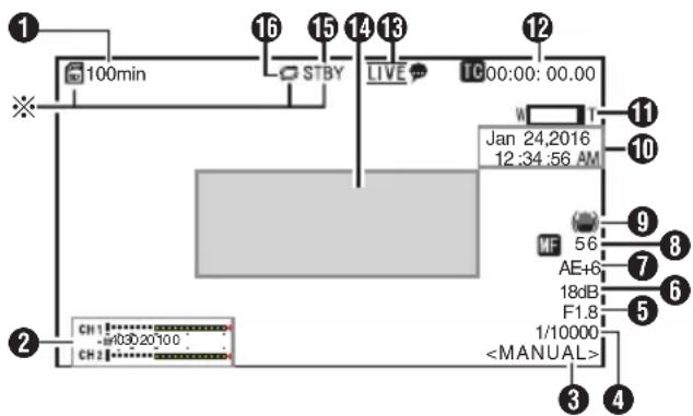
* Displayed only when a microSD card is inserted
① Remaining Space on Media Displays the remaining recording time on the microSD card.
!INVALID : When a microSD card writing/reading error has occurred, or when the microSD card is unrepairable.
!FORMAT : microSD card requires formatting.
!INCORRECT :
- Incompatible microSD card format.
!REC INH :
- When a microSDHC card is inserted while [4GB File Spanning(SDXC)] is set to "Off".
( P68 [ 4GB File Spanning(SDXC) ] )
The following icons are displayed during FTP upload.
( P83 [Uploading a Recorded Video Clip] )
| Icon Status | |
| FTP transfer is in progress. Three images are alternately displayed, and the arrows become animated. In this case, instead of the remaining recordable time on the microSD card, an estimated value of the remaining transfer time is displayed. | |
| Error has occurred during FTP transfer. | |
② Audio Level Meter
- Set [Audio] to "On" or "Off" to display or hide the level meter respectively.
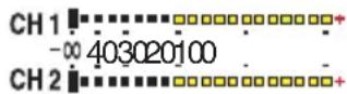
③ White Balance Mode
Displays the current white balance mode.
<3200K>: When the color temperature is set to 3200 K
<5600K>: When the color temperature is set to 5600K
4 Shutter
- Displays the current shutter speed when the [Exposure] selection button is set to "Shutter" or "Manual".
( P55 [ Shutter ] )
- When the [Exposure] selection button is set to "Auto" or "Iris", the shutter switches to the auto mode and the shutter speed is not displayed.
Memo :
- The variable range of the shutter speed varies according to the video format settings. (P44 [Setting the Electronic Shutter])
⑤ Iris F-Number
Displays F-number of the lens iris. (P42 [Adjusting the Iris])
Memo :
- A icon appears on the left side of the lens aperture value (F-number) during Auto Iris mode.
6 Gain
- Displays the gain value.
- An A icon is displayed to the left when [Exposure] is set to a value other than "Manual".
⑦ AE Level
- Displayed when the AE function is activated.
⑧ Focus Display
[AF] : When auto focus is selected [MF]** : When manual focus is selected
* **: indicates the focal length Focusing position is 0 = Near end Focusing position is 99 = Far end
* When manual focus is selected, pressing the [Push Auto]button each time changes the focal length value.
⑨ Image stabilizer mark Displayed when the image stabilizer is ON.
10 Date/Time Display Displays the current date and time.
Memo :
- The date/time display style can be specified in [Main Menu] [System] [Information Display] [Date Style]/[Time Style].
(→ P65 [ Date Style ] )
(P66 [ Time Style ] ) - This item is not displayed when [Main Menu] [System] [Information Display] is set to "Off". (P66 [Date/Time])
⑪ Zoom Display
- Displays the zoom position. (Zoom bar or value) Digital zoom off:

Digital zoom on:

- The zoom bar will only be displayed for 3 seconds after the zoom operation is activated.
- The value will always be displayed. Value: Z00 to 99
Digital zoom off: Z00 to 99
Digital zoom on : Z100 to 149
Memo :
- You can specify the display method (Number/Bar) in [Main Menu] [System] [Information Display] "Zoom".
⑫ Time Code (TC)/User's Bit (UB) Display
- Displays the time code (hour: minute: second: frame) or user's bit data recorded in the microSD card being played back.
• Example of time code display:

* Colon (:) denotes non-drop frames and dot (.) denotes drop frames.
• Example of user's bit display:
UBFF EE DD 20
Memo :
- You can specify whether to display the time code, user's bit, or turn off the display in [Main Menu] [System] [Information Display] [TC/UB]. This item will not be displayed when "Off" is selected. (P65 [TC/UB])
13 Live streaming mark
When [Main Menu] → [Network] → [Live Streaming Set] → [Live Streaming] is set to "On", the distribution status is displayed.
(▶ P61 [ Live Streaming ] )
| Icon Status | |
 (Red) (Red) | Distribution in progress (good connection quality) |
 (Red) (Red) | Distribution in progress (poor connection quality) |
 (Yellow) (Yellow) | Connection pending or connection failed |
⑭ Event/Warning Display Area
Displays error messages.
( P101 [Error Messages and Actions] )
15 Media Status
---- : No card found in the slot STBY : Recording standby
●REC : Recording
16 Loop Rec
Displayed while loop recording is in progress.
Status Screen
For checking the settings of the camera recorder.
* These are screen examples. The contents displayed are different depending on the settings.
LAN Screen
For viewing information related to the network of the [LAN] terminal.
(← P88 [Changing LAN Connection Settings])
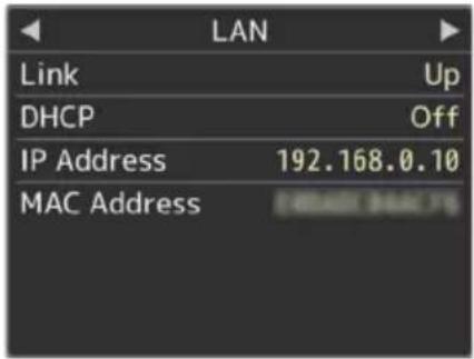
USB Screen
For viewing information related to the network of the [USB] terminal.
( P89 [Changing USB Connection Settings] )
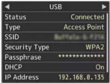
Live Streaming Screen
For viewing information related to live streaming. (P97 [Performing Live Streaming])
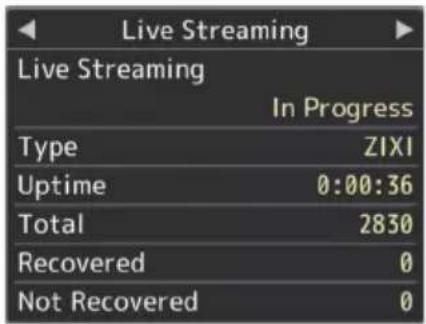
Planning Metadata Screen
For checking the current planning metadata setting.
(P80 [ Planning Metadata ] )
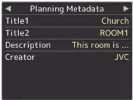
Connecting External Monitor
- To output live video images and audio sound to an external monitor, select the output signals from the camera, and connect using an appropriate cable according to the monitor to be used.
- Choose the most suitable terminal according to the monitor in use.
• [SDI OUT] terminal: Outputs 3G-SDI/HD-SDI signals.
• [HDMI] terminal: Outputs HDMI signals.
Memo :
- If the [SDI OUT] terminal or [HDMI] terminal is connected, configure the settings in the [A/V Set] menu according to the monitor to be connected.
( P59 [ HDMI/SDI Out ] ) - To display the menu screen or display screen on the external monitor, set [System] → [Information Display] to "On" and [Output] to "All".
Connecting via SDI
- Digital video signals, together with embedded (superimposed) audio signals and time code signals, are output for the 3G-SDI/HD-SDI signals.
Memo :
- The sampling frequency for embedded (superimposed) audio signals is 48 kHz. Time code of the built-in time code generator is also output.
Functions of Network Connection
- The network feature is able to function by using the [LAN] terminal at the back of the unit or by connecting one of the following adapters to the [USB] terminal.
- Wireless LAN adapter
- Ethernet adapter
- Cellular adapter
(1) P75 [Connecting to Network via [LAN]
Terminal] )
(USB P75 [Connecting to Network via [USB]
Terminal])
List of Functions
View Remote
You can access via a web browser on a PC to check the live image or remotely control the camera.
Live streaming
By combining with the decoder or PC application that supports live streaming, you can perform audio and video streaming via the network.
( P97 [Performing Live Streaming] )
Importing Metadata
You can download a metadata settings file (XML format) from the FTP server and store metadata in the camera recorder.
(P78 [Importing Metadata])
Uploading Recorded Clips
You can upload clips recorded in the microSD card to a preset FTP server.
( P83 [Uploading a Recorded Video Clip] )
Deleting Recorded Clips
You can delete clips that are recorded in a microSD card.
(→ P85 [Deleting Recorded Clips])
Editing Metadata
- Planning Metadata
You can access the page for editing the camera recorder's metadata via a web browser on a PC, and edit the metadata that is to be applied to clips to be recorded.
( P80 [ Planning Metadata ] )
- Clip Metadata
You can access the page for editing the metadata via a web browser on a PC, and display or rewrite the metadata that is recorded to a clip.
(▶ P81 [ Clip Metadata ] )
Loading and Saving Setup Files
You can save the camera settings to devices such as a PC, or load the settings that you have saved on a camera.
( P96 [Loading and Saving Setup Files] )
Firmware Update
You can update the version of the firmware on the camera. For details on how to update the firmware, please visit our corporate website (URL on the cover page).
Changing Network Connection Settings
( P87 [Changing Settings] )
Network Connection
| Operating Environment
Operation has been verified for the following environments.
Computer
- OS: Windows 7
Web browser: Google Chrome
- OS: Windows 10
Web browser: Google Chrome
• OS: Mac OS X 10.11
Web browser: Safari
Connecting to Network via [LAN] Terminal
1 Connect the [LAN] terminal of the camera with devices such as a PC or the RM-LP100 using a LAN cable.
2 Configure the connection settings.
- Select [Main Menu] [Network] [Connection Setup] [LAN Wizard] and press the Set button (Set).
- Pressing the button displays a network setting screen.
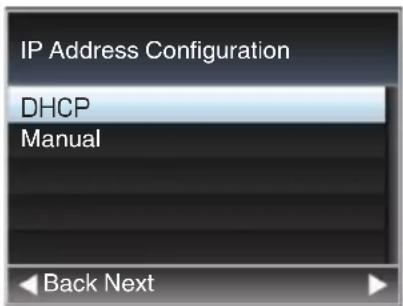
- Follow the screen instructions to complete setting. Perform setting for the following.
• IP address setting (DHCP or manual)
- IP Address
- Subnet mask
- Default gateway
- DNS Server
Memo :
- When anaddress is manually assigned in a NAT environment, it is also necessary to set the default gateway correctly besides conversion of the address at the router's end in order to perform operations such as access to the Internet from an external network via the router.
3 Setting is complete.
After setting is complete, you can access the camera recorder via a web browser. ( P87 [Changing Settings] )
Connecting to Network via [USB] Terminal
1 Connect an appropriate adapter according to the intended use to the [USB] terminal at the rear of the camera recorder.
The following adapters can be connected.
- Wireless LAN adapter
- Ethernet adapter
- Cellular adapter
Memo :
- Only a network connection adapter can be connected to the [USB] terminal.
- Connect or disconnect an adapter only after you have turned off the power of the camera recorder.
- You can find the latest information on the compatible adapters at the product page of our website.
2 Configure the connection settings.
- Select [Main Menu] [Network]
[Connection Setup] → [USB Wizard] and press the Set button (Set). - A wizard screen appears according to the type of adapter connected. Follow the instructions on the screen to perform setting.
( P76 [Connecting via Wireless LAN (USB)] )
(PT P77 [Connecting via Ethernet Adapter (USB)])
( P78 [Connecting via Cellular Adapter (USB)] )
Memo :
- When the menu is displayed on the Live View screen via the USB terminal, starting the USB wizard disconnects the network and the display will not be updated. Use the LAN terminal or video/audio output terminals such as the HDMI or SDI output terminal.
| Connecting via Wireless LAN (USB)
Connection via Access Point
1 Perform setting on the camera recorder, and start up the [USB Wizard] screen. (P75 [Connecting to Network via [USB] Terminal])
2 [Wireless LAN] appears on the [USB Wizard] screen.
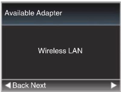
3 Press the ▶ button to display the [Select Connection Type] screen.
Select "Connect with Access Point".
Follow the screen instructions to complete setting. Perform setting for the following.
- Mode of connection
• Method of setting
* SSID, type of encryption, Passphrase, and IP Address setting (“DHCP” or “Manual”) in cases other than WPS
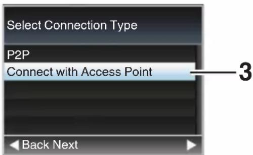
4 Setting is complete.
After setting is complete, you can access the camera recorder via a web browser. ( P87 [Changing Settings] )
P2P Connection
For direct access to the network feature of the camera from a PC.
1 [Wireless LAN] appears on the [Wizard] screen.
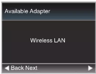
2 Press the ▶ button to display the [Select Connection Type] screen.
Select "P2P".
Follow the screen instructions to complete setting.
Perform setting for the following.
- Mode of connection
- Method of setting
* SSID and Passphrase in cases other than WPS
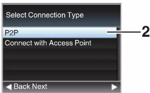
Memo :
- When "WPS" is selected in the [Select Setup Type] screen, the following steps 3 and 4 are not required.
3 Display the [USB] screen of the status screen.
- Press the [MENU] button on the infrared remote control twice to display the status screen.
Press the cross-shaped button (◀) to display the [USB] screen.
- Check to ensure that the [SSID] and [Passphrase] that you have set in the wizard are displayed.
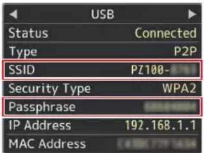
4 From the list of PC access points, select [SSID] and enter [Passphrase].
- Display the list of access points in the wireless connection settings of the PC and select "PZ100-*****". (***** are numbers that vary with the device used.)
- After the password confirmation screen appears, enter the [Passphrase] displayed on the [USB] screen.
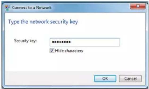
5 Setting is complete.
After setting is complete, you can access the camera recorder via a web browser. ( P87 [Changing Settings] )
Connecting via Ethernet Adapter (USB)
Connect a PC to the camera directly using a cross-over cable or via devices such as an Ethernet hub to access the network feature of the camera.
1 Connect the Ethernet adapter that is connected to the [USB] terminal of the camera to the PC using a LAN cable.
2 Perform setting on the camera recorder, and start up the [Wizard] screen.
( P75 [Connecting to Network via [USB] Terminal] )
3 [Ethernet] appears on the [Wizard] screen.
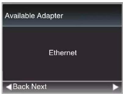
4 Press the ▶ button to display the [IP Address Configuration] screen.
Follow the screen instructions to complete setting. Perform setting for the following.
- IP address setting (DHCP or manual)
- IP Address
- Subnet mask
- Default gateway
- DNS Server
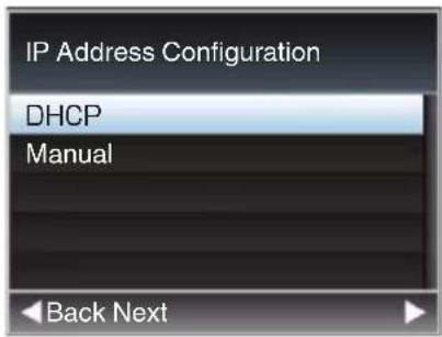
Memo :
- When an address is manually assigned in a NAT environment, it is also necessary to set the default gateway correctly besides conversion of the address at the router's end in order to perform operations such as access to the Internet from an external network via the router.
5 Setting is complete.
After setting is complete, you can access the camera recorder via a web browser. ( P87 [Changing Settings] )
| Connecting via Cellular Adapter (USB)
You can make use of the FTP function and live streaming function by connecting a cellular adapter to this camera recorder.
1 Perform setting on the camera recorder, and start up the [Wizard] screen.
( P75 [Connecting to Network via [USB] Terminal] )
2 [Cellular] appears on the [Wizard] screen.
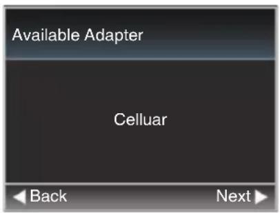
3 Press the ▶ button.
Follow the screen instructions to complete setting. Perform setting for the following.
- Connection phone number
- User name
- Password
Caution :
- Note that you may have to pay very high bills in the case of pay-per-use contracts. Fixed price contract is recommended if you are using the network function.
- Note that the use of improper settings may result in expensive bills from the phone service provider. Make sure that the setting is correct.
- To avoid expensive bills due to the roaming connection, you are recommended to use this function by disabling the roaming contract.
- There may be communication even when you are not using the network function. Remove the cellular adapter when the function is not in use.
Importing Metadata
You can download a metadata settings file (XML format) from the FTP server and store metadata in the camera recorder.
The imported metadata is applied to clips to be recorded.
Preparing Metadata
- You can record the four metadata types below.
Title1 : ASCII only, max. 63 characters (bytes)
Title2 : UNICODE, max. 127 bytes
Creator : UNICODE, max. 127 bytes
Description : UNICODE, max. 2047 bytes
- Metadata makes use of the XML description format.
- Edit the
?xml version="1.0" encoding="UTF-8"?
<NRT-MetalInterface lastUpdate="2015-01-29T18:06:21+09:00"
xmlns="urn:schemas-proHD:nonRealTimeMetaInterface:ver.1.00" xmlns:xsi="http://www.w3.org/2001/XMLSchema-instance">
<MetaData>
    <Title1>Title1 sample</Title1>
    <!-- only "en",max63bytes -->
    <Title2>Title2 sample</Title2>
    <!-- ,max127bytes -->
    <Description>Description sample</Description>
    <!-- ,max2047bytes -->
    <Creator>Creator sample</Creator>
    <!-- ,max127bytes -->
</MetaData>
</NRT-MetalInterface>
Configuring the Server for Downloading
For specifying the settings (server name, user name, password, etc.) for connecting to the FTP server for downloading the metadata as well as the path of the file to download.
1 Open the [Metadata Server] screen.
Open the [Main Menu] → [Network] → [Metadata Server] screen.
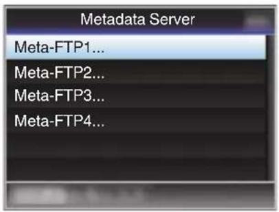
2 Register the [Metadata Server].
- Select a server using the cross-shaped button (▲▼), and press the Set button (Set). The server settings screen appears. Perform setting for each item.
- Up to 4 settings can be registered. (P64 [Metadata Server])
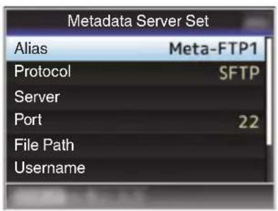
Memo :
- For detailson the registered information, please consult the network administrator for the server.
| Importing Metadata
Download the metadata settings file (XML format) from the FTP server.
1 Select [Main Menu] → [Network] → [Import Metadata] and press the Set button (Set).
The [Import Metadata] screen appears.
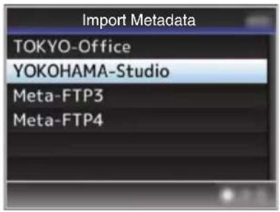
2 Select the server for importing the metadata.
- The name that is registered in [Metadata Server] [Alias] is displayed.
- Select a server using the cross-shaped button (▲▼), and press the Set button (Set).
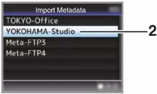
3 Select [Import] on the confirmation screen, and press the Set button (Set).
Import starts.
After import is complete, the display is restored to the screen before the [Import Metadata] screen appears.
![JVC KY-PZ100 - Select [Import] on the confirmation screen, and press the Set button (Set). - 1](/content/2026/05/813096/images/34e22223a4e42df1be390e7abf912cbd09821809052641d6db3af055c478b887.jpg)
flowchart
graph TD
    A["Import Metadata?"] --> B["TOKYO-Office"]
    B --> C["Import"]
    C --> D["Cancel"]
    E["Importing..."] --> F["End"]
Memo :
- You cannot exit the menu or perform recording while import is in progress.
- If import of the metadata failed, "Import Error!" is displayed, and a message indicating the cause of the error appears.
Press the Set button (Set) to return to the [Import Metadata] screen in step 1.
(P101 [List of FTP Transfer Errors])
- When "HTTP" is selected in the [Select FTP Proxy] screen of the network connection setting, connections to the servers other than "FTP" protocol cannot be made.
- If a setting other than "FTP" is specified for [Protocol], to ensure the safety of the communication path, a screen appears prompting you to validate the fingerprint of the public key and certificate received from the server.
Check to ensure that the displayed value coincides with the known value.
Editing Metadata
Planning Metadata
Access the page for editing the camera's metadata via a web browser on a PC, and edit the metadata that is to be applied to clips to be recorded.
1 Display the web setting screen.
Press the Setting button on the web browser screen of the PC to display the setting screen.
2 Click the [Planning Metadata] button to open the [Planning Metadata] screen.
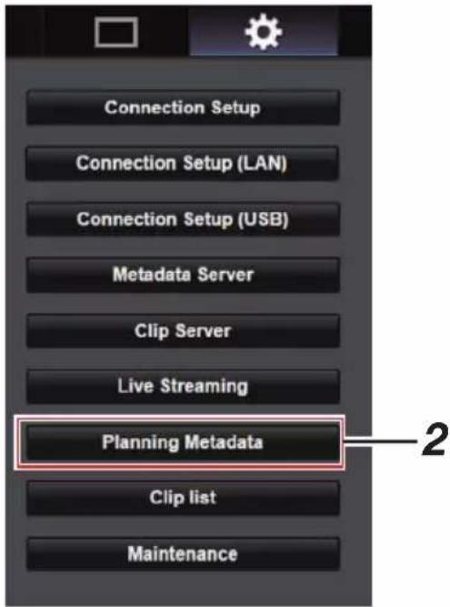
3 Edit the metadata.
① Enter information for the necessary fields.
② Afterinput is complete, click [Save] to overwrite the metadata.
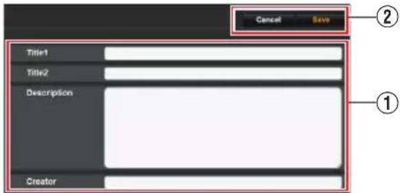
4 Click [OK] on the confirmation screen.
- Update of the [Planning Metadata] starts.
- After update is complete, "Renewal of planning metadata is succeeded." is displayed. Click [OK].
- Returns to the screen in step 3.
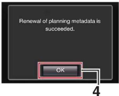
Memo :
- If update failed, "Renewal of planning metadata is failed." is displayed.
Click [Close] to return to the screen of 3.
| Clip Metadata
Access the page for editing the metadata via a web browser on a PC, and display or rewrite the metadata that is recorded to a clip.
1 Display the web setting screen.
Press the Setting button on the web browser screen of the PC to display the setting screen.
2 Display the clip list.
Click the [Clip list] tab to display the clip list.
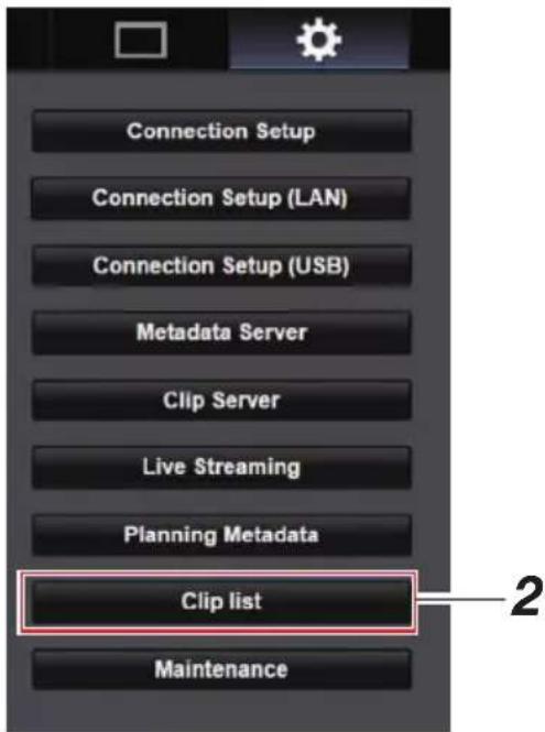
3 Set the camera recorder to the "Remote Edit Mode".
① You will see a message indicating "It is necessary to change the camera mode to "Remote Edit Mode". Change the mode." on the web browser.
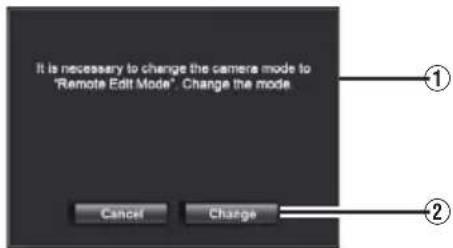
② Click [Change] to switch the camera to the Remote Edit mode.

Memo :
- When the menu or status is displayed, display of the confirmation screen will be put on hold.
- If the menu is displayed on the camera recorder, close the menu.
- If the status is displayed on the camera recorder, close the status display.
- When FTP upload via the camera unit is currently in progress, switching to the Remote Edit mode is disabled.
4 Select the Metadata Edit mode.
Select the [Meta data] tab.
5 Select the clip to rewrite the metadata.
- A list of the recorded clips appears on the [Clip list] screen.
- Click on the clip for which you want to rewrite the metadata.
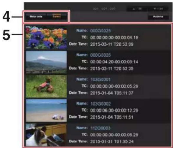
Memo :
- You can use the [▲-30] or [▼+30] tab to jump to the previous or next 30 clips on the list.
6 Edit the metadata of the selected clips.
① Edit the information for the necessary fields.
② You can click the [OK Mark] to add an OK mark to or delete it from the selected clips.
③ After editing is complete, click [Save] to overwrite the metadata.
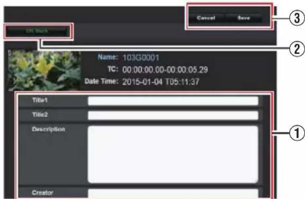
7 Click [OK] on the confirmation screen.
- Update of the metadata starts.
- After update is complete, "Renewal of clip metadata is succeeded." is displayed. Click [OK].
- Returns to the screen in step 4.
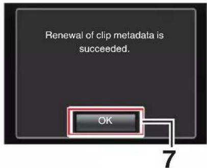
Memo :
- If update failed, "Renewal of clip metadata is failed." is displayed.
Click [Close] to return to the screen of 4.
Uploading a Recorded Video Clip
- You can upload clips recorded in the microSD card to a preset FTP server.
- You can upload selected clips, all clips, or those appended with an OK mark.
Configuring the FTP Server for Uploading
( P91 [Changing Clip Server Settings] )
| Uploading Video Clips
1 Display the web setting screen.
Press the Setting button on the web browser screen to display the setting screen.
2 Display the clip list.
Click the [Clip list] tab on the setting screen to display the clip list.
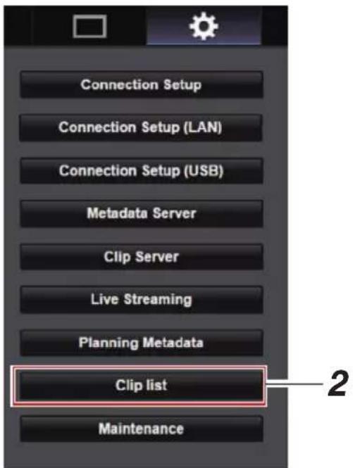
3 Set the camera recorder to the "Remote Edit Mode".
① You will see a message indicating "It is necessary to change the camera mode to "Remote Edit Mode". Change the mode." on the web browser.
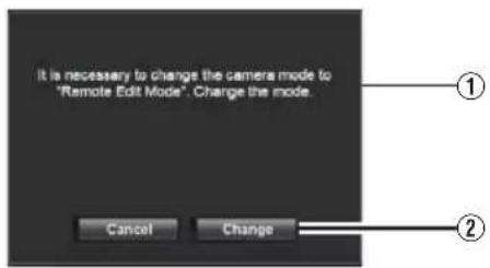
② Click [Change] to switch the camera to the Remote Edit mode.

4 Select the selection mode.
Press the Select button.
5 Select the clip you want to upload.
- A list of the recorded clips appears on the [Clip list] screen.
- Click on the clip you want to upload to make a selection.
- Clips beingselected are indicated by a check mark.
Memo :
- You can use the [▲-30] or [▼+30] tab to jump to the previous or next 30 clips on the list.
6 Select the upload operation.
Click the [Actions] button.

7 Select a method to upload the clips.
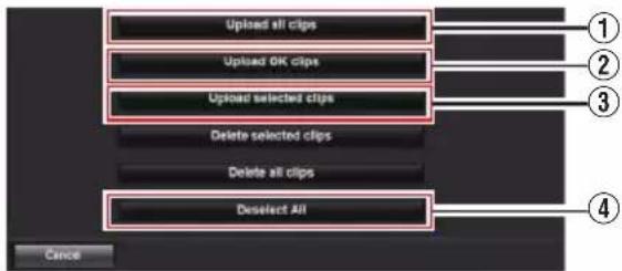
① Upload all clips
Uploads all the clips in the displayed slots. Click to move to the [Clip Server] screen.
② Upload OK clips
Uploads all clips in the displayed slots that are appended with an OK mark. Click to move to the [Clip Server] screen.
③ Upload selected clips
Uploads the clips you have selected. Click to move to the [Clip Server] screen.
④ Deselect All
Clears all clip selection and returns to the [Clip List] screen.
8 Select the clip server and start uploading.
- Upon selecting the server to upload clips to, an upload screen appears.

- The status of the transfer process is indicated by a progress bar.

Memo :
- To stop transfer, click the [Stop] button. Clicking [Yes] on the confirmation screen stops the transfer halfway and brings you back to the main page.
- If there already exists a file on the FTP server with a name identical to the file to be transferred, a confirmation screen asking to overwrite the file will appear.
However, if "HTTP" is selected in the [Select FTP Proxy] screen of the network connection settings, an overwrite confirmation screen does not appear, and the existing file will be overwritten directly.
- When "HTTP" is selected in the [Select FTP Proxy] screen of the network connection setting, the overwrite confirmation window will not be displayed and the existing file is overwritten.
- When FTP transfer starts and there is a file of the same name on the server with a file size smaller than the file to be transferred, the file on the server will be regarded as an interrupted file during a FTP transfer. A confirmation screen to resume transfer (append writing) appears.
- If "Resume" is selected, FTP transfer is carried out such that it appends from the position where it was interrupted.
When FTP transfer ends normally, "Complete" appears on the screen.
- After uploading in step 8 has started, other web browser operations are disabled until uploading is complete.
- If a setting other than "FTP" is specified for [Protocol], to ensure the safety of the communication path, a screen appears prompting you to validate the fingerprint of the public key and certificate received from the server.
Check to ensure that the displayed value coincides with the known value.
- Fingerprint is a unique value that varies with each public key and certificate. - For details of the fingerprint, please consult the administrator of the server to be connected.
(▶ P63 [ Clip Server ] )
- When "HTTP" is selected in the [Select FTP Proxy] screen of the network connection setting, connections to the servers other than "FTP" protocol cannot be made.
9 Upload is complete.
- After upload is complete, "Successfully Completed." appears on the screen.
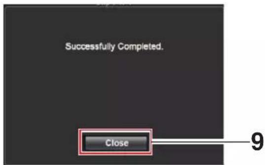
- When clips are not uploaded successfully, the following errors are displayed.
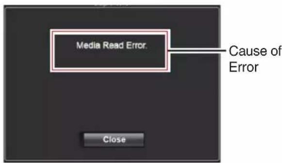
(P101 [List of FTP Transfer Errors])
Memo :
- Follow "[List of FTP Transfer Errors] (P 101)" to clear the error message.
Deleting Recorded Clips
You candete clips that are recorded in a microSD card.
1 Display the web setting screen.
Press the Setting button on the web browser screen to display the setting screen.
2 Display the clip list.
Click the [Clip list] tab on the setting screen to display the clip list.
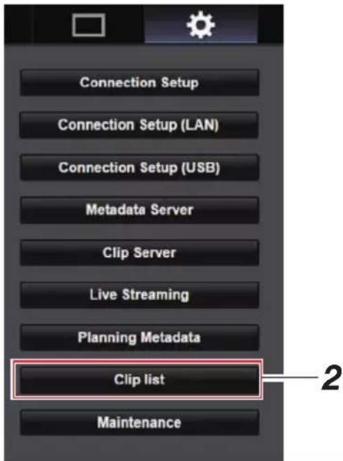
3 Set the camera recorder to the "Remote Edit Mode".
① You will see a message indicating "It is necessary to change the camera mode to "Remote Edit Mode". Change the mode." on the web browser.
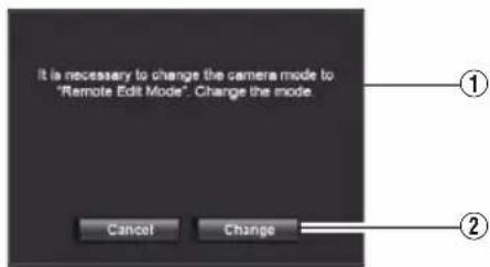
② Click [Change] to switch the camera to the Remote Edit mode.

4 Select the selection mode.
Press the Select button.
5 Select the clips you want to delete.
- A list of the recorded clips appears on the [Clip list] screen.
- Click on the clip you want to delete to make a selection.
- Clips being selected are indicated by a check mark.
Memo :
- You can use the [▲-30] or [▼+30] tab to jump to the previous or next 30 clips on the list.
6 Choose a delete action.
Click the [Actions] button.
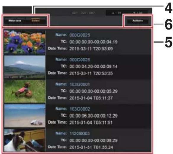
7 Select a way to delete the clips.
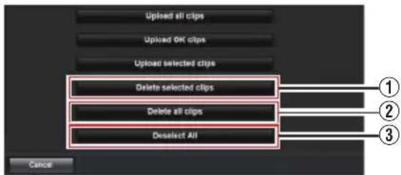
① Delete selected clips Deletes only the selected clips.
② Delete all clips Deletes all the clips in the displayed slots.
③ Deselect All Clears all clip selection and returns to the [Clip list] screen.
8 Start clip deletion.
Press the [OK] button to start deleting the clips.
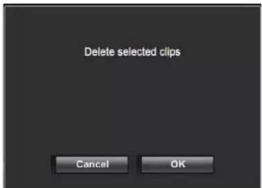
The status of the deletion process is indicated by a progress bar.

Memo :
- To stopdeletion, click the [Stop] button. Clicking [Yes] on the confirmation screen stops the deletion halfway and brings you back to the main page.
- After deletion in 8 has started, other web browser operations are disabled until deletion is complete.
9 Deletion is complete.
- After deletion is complete, "Successfully Completed." appears on the screen.
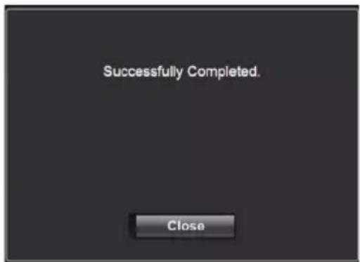
Changing Settings
You can change the network-related settings by accessing via a web browser on a PC.
1 Display the web setting screen.
Press the Setting button on the web browser screen of the PC to display the setting screen.
2 Select an item for which you want to change the setting from the [Settings] screen.
Set each of the items as follows.
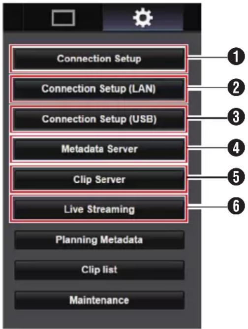
① Connection Setup
For specifying connection settings that are common between the LAN and USB terminals.
② Connection Setup (LAN)
For changing the connection settings for the LAN terminal.
③ Connection Setup (USB)
For changing the connection settings for the USB terminal.
4 Metadata Server
Settings on the server for importing the metadata.
Setting can be performed in the same way as the Metadata Server menu on the camera recorder.
The latest settings are reflected, regardless of whether they are specified via the camera recorder or web operation.
⑤ Clip Server
Settings for the server to upload recorded clips to.
Setting can be performed in the same way as the [Clip Server] menu on the camera recorder.
The latest settings are reflected, regardless of whether they are specified via the camera recorder or web operation.
6 Live Streaming
Setting for streaming audio and video via the network.
The latest settings are reflected, regardless of whether they are specified via the camera recorder or web operation.
Memo :
- Priority is given to menu operation on the camera recorder.
- When the menu on the camera recorder is opened while the [Settings] screen is opened using a web browser, a warning appears, after which the display returns to the main screen.
- While the menu is displayed on the camera recorder, the [Settings] screen cannot be opened via the web browser.
Changing Common LAN/USB Connection Settings
For specifying network settings that are common between the LAN and USB terminals.
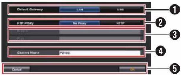
1 Default Gateway
For selecting whether to use the default gateway setting for the LAN or USB terminal. Select LAN if the router for connecting to an external network is located at the LAN terminal. Select USB if you want to access an external network via an adapter that is connected to the USB terminal. If you are connecting a cellular adapter to the USB terminal, select USB.
② FTP Proxy
Select HTTP if you are using a proxy for FTP transfer.
③ FTP Proxy Settings
For setting the server name and port number if you are using an FTP proxy.
4 Camera Name
For setting the camera name that appears at the bottom left corner of the Live View screen.
* Enter not more than 8 characters using single-byte alphanumeric characters (a to z, 0 to 9), single-byte hyphen [-], underscore [_] or space [ ].
⑤ [OK]/[Cancel] Button For saving the settings or canceling the action.
| Changing LAN Connection Settings
You can change the settings for each of the preset items on the [LAN Wizard] screen of the camera recorder.
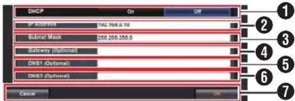
① DHCP
For selecting whether to use DHCP or not.
If you are using DHCP, select "On" and press the [OK] button. The following items will be grayed out when "On" is selected, and input is not required.
If you are not using DHCP, select Off, input accordingly for the following items and press the [OK] button.
② IP Address
For entering the IP address of the camera.
③ Subnet Mask
For entering the subnet mask of the camera.
4 Gateway (Optional)
For entering the gateway address. (Optional)
⑤ DNS1 (Optional)
For entering the primary DNS server address.
(Optional)
⑥ DNS2 (Optional)
For entering the secondary DNS server address. (Optional)
⑦ [OK]/[Cancel] Button
After changing of settings is complete, click the [OK] button.
| Changing USB Connection Settings
You can change the settings for each of the preset items on the [USB Wizard] screen of the camera recorder.
- Items that cannot be changed are grayed out according to the type of adapter connected and the mode of connection.
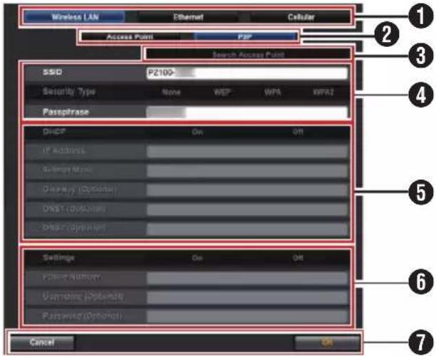
① Type of Adapter Connected
② Mode of Wireless LAN Connection
③ [Search Access Point] Button
Click to display a list of the detected access points.
A check mark ( ) appears at the beginning of the access point that is currently selected.
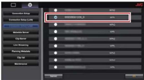
④ For configuring information required for connecting to a wireless LAN access point.
⑤ IP Address Configuration
When "DHCP" is selected, all items will be grayed out.
⑥ Settings when using cellular adapter
⑦ [OK]/[Cancel] Button
After changing of settings is complete, click the [OK] button.
Clicking [Execute] on the confirmation screen changes the settings on the camera and restarts the network.
Memo :
- You can run [Search Access Point] only when the setting screen is displayed by connecting to the network using the LAN terminal or when it is displayed via an access point by connecting to the network using the USB terminal.
| Changing Metadata Server Settings
You can make direct changes to the FTP server for importing the metadata that is specified in [Metadata Server] on the [Settings] screen, as well as the path of the file to import.
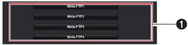
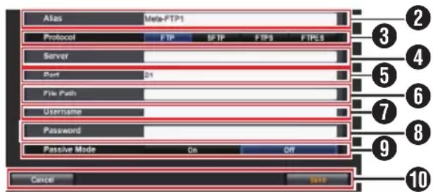
① Server
For selecting the FTP server.
② Alias
For setting a name to distinguish the settings of this camera recorder.
The name set in this item will be displayed in the [Import Metadata] options.
* Enter not more than 31 characters.
3 Protocol
For setting the protocol of the FTP server to be connected.
- FTP: Protocol that does not encrypt the incoming and outgoing data.
- SFTP: Protocol that encrypts incoming and outgoing data using SSH.
- FTPS: Protocol that encrypts incoming and outgoing data using SSL or TLS. It uses an implicit mode (starts encrypted communication once connection starts).
- FTPES: Protocol that encrypts incoming and outgoing data using SSL or TLS. It uses an explicit mode (starts encrypted communication after permission is granted).
4 Server
For setting the server name ("mystation.com", etc.) or the IP address ("192.168.0.1", etc.) of the FTP server.
* Enter not more than 127 characters using single-byte alphanumeric characters (a to z, 0 to 9), single-byte hyphen [-], or dot [.].
5 Port
Enter the FTP server port number to use using an integer between 1 and 65535.
The default value varies with the Protocol setting.
(FTP: 21, SFTP: 22, FTPS: 990, FTPES: 21)
⑥ File Path
Enter the path name for the metadata file (“/pub/meta.xml”, “/home/user/meta2.xml”, etc.)
* Enter not more than 127 characters.
⑦ Username
Enter the user name for connecting to the FTP server.
* Enter not more than 31 characters.
8 Password
Enter the password for connecting to the FTP server.
* Enter not more than 31 characters.
9 Passive Mode
For setting whether to set the communication mode used for file transfer to the passive mode. Set to "On" if the camera is inside a firewall, and a connection from the FTP server to the camera cannot be established.
[Setting Values: On, ●Off]
Memo :
- When [Protocol] is set to "SFTP", this item appears as “----” and cannot be selected.
⑩ [Save]/[Cancel] Button
For saving the settings or canceling the action.
| Changing Clip Server Settings
You can make direct changes to the server and directory settings that are specified in [Clip Server] on the [Settings] screen for uploading recorded clips in the microSD card to the FTP server.

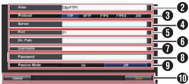
① Server
For selecting the FTP server.
② Alias
For setting a name to distinguish the settings of this camera recorder.
The name set in this item will appear on the [FTP Upload] action screen of the clip list display.
* Enter not more than 31 characters.
3 Protocol
For setting the protocol of the FTP server to be connected.
- FTP:
Protocol that does not encrypt the incoming and outgoing data. - SFTP: Protocol that encrypts incoming and outgoing data using SSH.
- FTPS: Protocol that encrypts incoming and outgoing data using SSL or TLS. It uses an implicit mode (starts encrypted communication once connection starts).
- FTPES: Protocol that encrypts incoming and outgoing data using SSL or TLS. It uses an explicit mode (starts encrypted communication after permission is granted).
• ZIXI:
Select this item when transferring files via the ZIXI server.
[Setting Values: ●FTP, SFTP, FTPS, FTPES, ZIXI]
Memo :
- To use the "ZIXI" setting, a dedicated server is needed separately.
- If "ZIXI" is set, the resume function is enabled.
4 Server
For setting the server name ("mystation.com", etc.) or the IP address ("192.168.0.1", etc.) of the FTP server.
* Enter not more than 127 characters using single-byte alphanumeric characters (a to z, 0 to 9), single-byte hyphen [-], or dot [.].
5 Port
Enter the FTP server port number to use using an integer between 1 and 65535.
The default value varies with the Protocol setting.
(FTP: 21, SFTP: 22, FTPS: 990, FTPES: 21, ZIXI: 2088)
6 Dir. Path
Enter the path name for the directory to upload to (“/pub”, “/home/user”, etc.)
* Enter not more than 127 characters.
⑦Username
Enter the user name for connecting to the FTP server.
* Enter not more than 31 characters.
8 Password
Enter the password for connecting to the FTP server.
* Enter not more than 31 characters.
9 Passive Mode
For setting whether to set the communication mode used for file transfer to the passive mode. Set to "On" if the camera is inside a firewall, and a connection from the FTP server to the camera cannot be established.
[Setting Values: On, ●Off]
Memo :
- When [Protocol] is set to "SFTP", this item appears as “----” and cannot be selected.
⑩[Save]/[Cancel] Button
For saving the settings or canceling the action.
| Changing Live Streaming Settings
You can make direct changes to information on the destination of distribution that is specified in [Live Streaming] on the [Settings] screen.
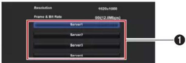
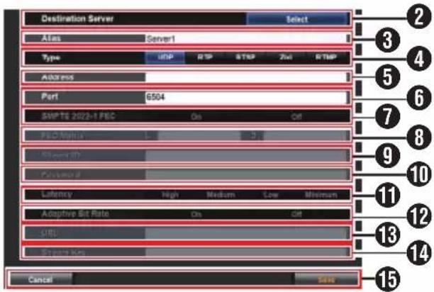
① Server
For selecting the server for live streaming.
② Destination Server
Press the Select button if you want to configure a server at the receiving end of the live distribution.
③ Alias
For setting a name to distinguish the settings of this camera.
The name set in this item will be displayed in the [Server] options.
* The default value is "Server1"/"Server2"/"Server3"/"Server4".
* You can enter up to 31 characters and ASCII characters.
4 Type
For setting the system to transfer videos for distribution.
Memo :
- Use reception devices that are compatible with the respective transfer systems.
- To use the "ZIXI" setting, a dedicated server is needed separately.
- The following items that can be set vary depending on the setting of this item.
⑤ Address
For setting details such as the host name and the IP address of the live distribution destination.
* Enter not more than 127 characters using single-byte alphanumeric characters (a to z, 0 to 9), single-byte hyphen [-], or dot [.].
6 Port
Enter the network port number of the live distribution destination using an integer between 1 and 65535.
When [Type] is set to "UDP" (MPEG2-TS/UDP) or "RTP" (MPEG2-TS/RTP), the default value is "6504". If "ZIXI" is set, the default value is "2088".
⑦ SMPTE 2022-1 FEC
Set to "On" to use FEC (Forward Error Correction).
A transmission system that recovers the missing packets in the decoding process without having to retransmit the missing packets.
* The decoder must be compatible with SMPTE 2022-1.
8 FEC Matrix
For setting the amount of FEC (Forward Error Correction) overhead for configuring SMPTE2022-1.
* Setting range
- 4 ≤ L ≤ 20 (Default value: L = 10 )
- 4 ≤ D ≤ 20 (Default value: D = 10 )
- L × D ≤ 100 (Default value: L × D = 10 × 10 )
Memo :
- This item is selectable only when [SMPTE 2022-1 FEC] is set to "On".
- Increasing the amount of FEC overhead increases the packet loss resilience but more network bandwidth is used.
- Even with the same amount of overhead, increasing the L value will increase the packet loss (continuous packet loss) resilience.
9 Stream ID
For setting the registered stream ID of the live distribution destination. The default value varies with the product model.
* Enter not more than 63 characters.
10 Password
For setting the [Stream ID] password. There is no default value (blank).
* Enter not more than 127 characters.
⑪ Latency
For setting the latency mode.
12 Adaptive Bit Rate
If “On” is selected, the bit rate setting value of live streaming is set to maximum limit, and the bit rate is changed automatically according to changes in the network bandwidth.
Memo :
- [Adaptive Bit Rate] is selectable when[Type] is set to "ZIXI" and [Latency] is set to a value other than "Minimun(ZIXI Off)".
* The bit rate is displayed on the status screen only when "On" is set.
13 URL
For entering the URL of the live distribution destination beginning with "rtmp://".
There is no default value (blank).
* You can enter up to 191 characters and ASCII characters.
14 Stream Key
Enter the stream key specified at the live transmission destination.
There is no default value (blank).
* Enter not more than 63 characters.
15 [Save]/[Cancel] Button
For saving the settings or canceling the action.
Managing the Network Connection Settings File
This camera recorder allows you to save the network connection settings on the [USB Wizard] screen to the camera recorder unit.
Loading a saved connecting settings file enables you to reproduce the appropriate network connection state speedily.
Memo :
- To save or retrieve the connection settings, go to [Main Menu] [Network] [Connection Setup].
- The following operations can be performed on the [Connection Setup] menu.
- [Saving the Connection Settings File] (P 94)
- [Reading the Connection Settings File] (P 95)
- [Deleting Connection Settings] (P 95)
Number of Storable Setup Files
Camera recorder : [CAM1] to [CAM4]
| Saving the Connection Settings File
1 Select [Main Menu] → [Network] → [Connection Setup] and press the Set button (Set).
2 Select [Store] and press the Set button (Set).
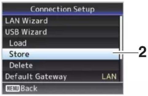
3 Select the file you want to save as a new file (or overwrite an existing file) using the cross-shaped button (▲▼), and press the Set button (Set).
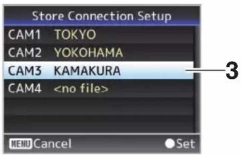
4 Name the file.
Enter the subname using the software keyboard.
( P53 [Text Input with Software Keyboard] )
Memo :
- When overwriting an existing file, the subname of the existing file is displayed.
- Select [Cancel], and press the Set button (Set) to return to the previous screen.
5 Select [Store] and press the Set button (Set).
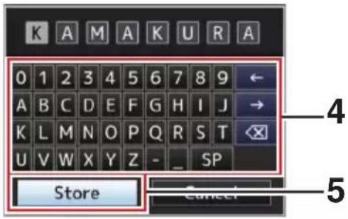
6 Save the file.
- A confirmation screen appears when you choose to overwrite. Select [Overwrite] on the confirmation screen, and press the Set button (Set). Saving starts, and "Storing..." appears on the screen.
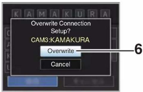
- Saving starts, and "Storing..." appears on the screen when the file is newly saved.
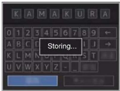
7 Saving is complete.
After saving of the file is complete, "Complete" appears on the screen, and the menu screen closes automatically.
| Reading the Connection Settings File
1 Select [Main Menu] → [Network] → [Connection Setup] and press the Set button (Set).
2 Select [Load] and press the Set button (Set).
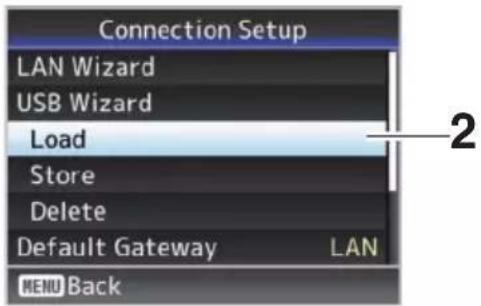
3 Select the file to load using the cross-shaped button (▲▼), and press the Set button (Set).
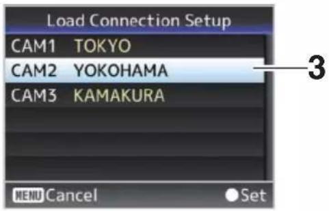
4 Select [Load] on the confirmation screen, and press the Set button (Set).
Loading starts, and "Loading..." appears on the screen.
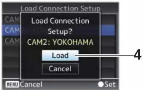
5 Reading is complete.
After reading of the file is complete, "Complete" appears on the screen, and the menu screen closes automatically.
| Deleting Connection Settings
1 Select [Main Menu] → [Network] → [Connection Setup] and press the Set button (Set).
2 Select [Delete] and press the Set button (Set).
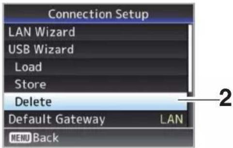
3 Select the file to delete using the cross-shaped button (▲▼), and press the Set button (Set).
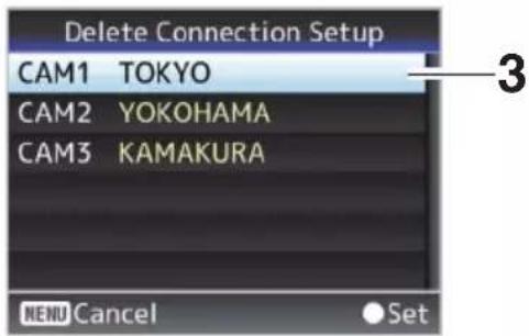
4 Select [Delete] on the confirmation screen, and press the Set button (Set).
Deletion starts, and "Deleting..." appear on the screen.
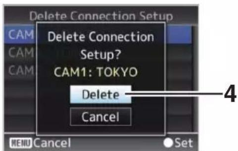
5 Deletion is complete.
After file deletion is complete, "Complete" appears on the screen.
Loading and Saving Setup Files
You can load the setup file to the camera (upload) or save it to a PC (download) from the Maintenance page on the web browser screen. A "Camera mode will be changed to "Maintenance Mode". During "Maintenance Mode", functions of the camera are stopped." message appears. Click [Change] to switch the camera to the Maintenance mode.
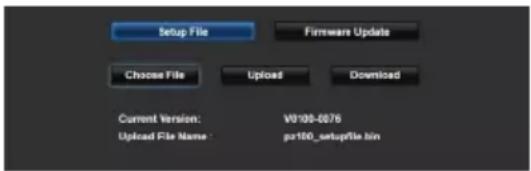
Loading (Uploading) Setup Files
1 Press the [Setup File] button.
Pressing the button switches to setup file upload/download mode.
2 Press the [Choose File] button to select the setup file to upload.
Pressing the button displays a file selection dialog box. Select the file you want to upload. After a file has been selected, the name of the loaded file appears in "Upload File Name :". "----" appears if no file has been loaded.
3 Press the [Upload] button to start uploading of the file.
Pressing the button displays a "OK"/"Cancel" confirmation message.
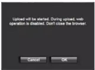
4 Press the [OK] button.
Pressing the button starts uploading of the file. Progress of the uploading process is shown at the bottom of the screen.
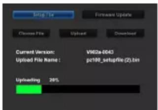
After uploading is complete, a message screen appears.
5 Press the [OK] button.
Pressing the button restarts the camera.
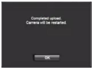
Saving (Downloading) Setup Files
1 Press the [Setup File] button.
Pressing the button switches to setup file upload/download mode.
2 Press the [Download] button to start downloading of the file.
The file will be saved to the predetermined download folder.
A dialog box prompting you to save the file may appear depending on the browser that you are using.
Specify the destination to save the downloaded file.
Performing Live Streaming
By combining with the decoder or PC application that supports live streaming, you can perform audio and video streaming via the network.
| Supported Formats
Video
H.264
1920x1080 (59.94p/50p) 20/16/12/8Mbps (Max)
1920x1080 (59.94i/50i) 20/16/12/8/5/3Mbps
(Max)
1920x1080 (29.97p/25p) 20/16/12/8/5/3Mbps
(Max)
1280x720 (59.94p/50p) 20/16/12/8/5/3Mbps
(Max)
1280x720 (29.97p/25p) 8/5/3/1.5Mbps (Max)
640x360 (29.97p/25p) 3/1.5/0.8/0.3Mbps (Max)
Memo :
- Depending on the type of network adapter used and the connection, the images and audio sound during live streaming can be choppy.
Audio
AAC
| Supported Protocols
MPEG2-TS/UDP
MPEG2-TS/RTP
RTSP/RTP
ZIXI
RTMP
| Setting Distribution
1 Select the terminal for live streaming.
Specify the settings in [Main Menu] → [Network] → [Interface].
( P61 [ Interface ] )
2 Set the Resolution and Frame & Bit Rate for the video to be distributed.
Specify the settings in [Main Menu] → [Network] → [Live Streaming Set].
( P61 [ Live Streaming Set ] )
For more information on the live streaming settings, please refer to [[Live Streaming Set]
Combinations that Support Distribution] (P 98).
3 Specify the distribution protocol and related items.
Specify the distribution protocol and related items in [Main Menu] → [Network] → [Live Streaming Set] → [Streaming Server].
( P61 [ Streaming Server ] )
4 Select the server for live streaming.
Select the distribution server in [Main Menu] → [Network] → [Live Streaming Set] → [Server].
( P61 [ Server ] )
[Live Streaming Set] Combinations that Support Distribution
■ LAN terminal
| Resolution | 1920 x 1080 | 1280 x 720 | 640 x 360 | |||||||||||||||||||||||||||||
| Frame Rate | 60p, 50p | 60i, 50i, 30p, 25p 60p, 50p | 30p, 25p 30p, 25p | |||||||||||||||||||||||||||||
| Type Bitrate | MPEG2-TS/UDP | MPEG2-TS/RTP | RTSP | ZIXI(*1) | ZIXI(*2) | RTMP | MPEG2-TS/UDP | MPEG2-TS/RTP | RTSP | ZIXI(*1) | ZIXI(*2) | RTMP | MPEG2-TS/UDP | MPEG2-TS/RTP | RTSP | ZIXI(*1) | ZIXI(*2) | RTMP | MPEG2-TS/UDP | MPEG2-TS/RTP | RTSP | ZIXI(*1) | zIXI(*2) | RTMP | MPEG2-TS/UDP | MPEG2-TS/RTP | RTSP | ZIXI(*1) | ZIXI(*2) | RTMP | ||
| 20 Mbps | √* | √* | √* | |||||||||||||||||||||||||||||
| 16 Mbps | √ | √* | √*√ | √*√ | ||||||||||||||||||||||||||||
| 12 Mbps | √ | √ | √ | √ | √ | √ | ||||||||||||||||||||||||||
| 8 Mbps | √ | √ | √ | √√* | √ | √ | √√* | √ | √ | √√* | √ | |||||||||||||||||||||
| 5 Mbps | √ | √ | √ | √ | √ | √ | √ | √ | *√ | √ | √ | √ | √ | √ | *√ | √ | √ | √ | * | |||||||||||||
| 3 Mbps | √ | √ | √ | √ | √ | √ | √ | √ | √ | √ | √ | √ | √ | √ | √ | √ | √ | √ | √ | √ | ||||||||||||
| 1.5 Mbps | √ | √ | √ | √√√√ | ||||||||||||||||||||||||||||
| 0.8 Mbps | √ | √ | ||||||||||||||||||||||||||||||
| 0.3 Mbps | √ | √ | ||||||||||||||||||||||||||||||
√ : Supports distribution
√* : Supports distribution (Depending on factors such as the type of device connected and the network environment, images and audio sound during live streaming may be choppy. When this occurs, try lowering the bit rate setting.)
*1 When [Latency] is set to a value other than "Low"
*2 When [Latency] is set to "Low"
USB terminal
| Resolution | 1920 x 1080 | 1280 x 720 | 640 x 360 | ||||||||||||||||||||||||||||||
| Frame Rate | 60p, 50p | 60i, 50i, 30p, 25p 60p, 50p | 30p, 25p 30p, 25p | ||||||||||||||||||||||||||||||
| Type Bitrate | MPEG2-TS/UDP | MPEG2-TS/RTP | RTSP | ZIXI(*1) | ZIXI(*2) | RTMP | MPEG2-TS/UDP | MPEG2-TS/RTP | RTSP | ZIXI(*1) | ZIXI(*2) | RTMP | MPEG2-TS/UDP | MPEG2-TS/RTP | RTSP | ZIXI(*1) | ZIXI(*2) | RTMP | MPEG2-TS/UDP | MPEG2-TS/RTP | RTSP | ZIXI(*1) | zIXI(*2) | RTMP | MPEG2-TS/UDP | MPEG2-TS/RTP | RTSP | ZIXI(*1) | ZIXI(*2) | RTMP | |||
| 12 Mbps | √ | √ | √ | ||||||||||||||||||||||||||||||
| 8 Mbps | √√√ | √ | √ | √ | √ | √ | |||||||||||||||||||||||||||
| 5 Mbps | √ | √ | √* | √ | √ | √* | √ | √ | √* | ||||||||||||||||||||||||
| 3 Mbps | √ | √ | √ | √ | √ | √ | √ | √ | √ | √ | √ | √ | √ | √ | √ | √ | √ | √ | √ | ||||||||||||||
| 1.5 Mbps | √ | √ | √ | √√√√ | |||||||||||||||||||||||||||||
| 0.8 Mbps | √ | √ | |||||||||||||||||||||||||||||||
| 0.3 Mbps | √ | √ | |||||||||||||||||||||||||||||||
√ : Supports distribution
√*: Supports distribution (Depending on factors such as the type of device connected and the network environment, images and audio sound during live streaming may be choppy. When this occurs, try lowering the bit rate setting.)
*1 When [Latency] is set to a value other than "Low"
*2 When [Latency] is set to "Low"
Memo :
- The settings cannot be changed during live streaming (when [Streaming] is set to "On").
- Depending on the type of network adapter used and the connection, images and audio sound during live streaming may be choppy.
Starting Distribution
1 Perform the necessary setting for the decoder and PC application.
For details on the settings, please refer to the "INSTRUCTIONS" of the respective devices and applications.
Memo :
- If there is an NAT router within the communication path between the camera and the decoder, port forwarding setup is required. For details on the settings, please refer to the "INSTRUCTIONS" of the router in use.
- The following parameters are required when connecting to this camera recorder using the RTSP/RTP.
Port number: 554
Stream ID: stream - Use the following to access via URL. rtsp://
:554/stream
2 With the network connection established, set [Live Streaming] to "On".
( P36 [Live streaming On/Off button] )
- Set [Main Menu] [Network] [Live Streaming Set] [Live Streaming] to "On".
Memo :
- You can check the status of distribution on the status screen.
(▶ P72 [Live Streaming Screen])
| Icon Status | |
 | Distribution in progress (good connection quality)Blinks when distribution starts or stops |
 | Distribution in progress (poor connection quality) |
 | Waiting for connection (during RTSP/RTP) or connection failed |
- When the 📋 icon is displayed, you can view the details of the error on the [Live Streaming] screen of the status screen.
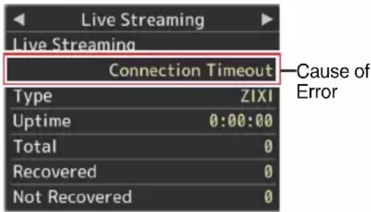
(▶ P103 [List of Live Streaming Error Displays])
Caution :
- Streaming may be interrupted momentarily approximately every 24 hours after the process started.
Setting the FEC Matrix
Set the amount of FEC (Forward Error Correction) overhead for configuring SMPTE2022-1.
1 Select [Main Menu] → [Network] → [Live Streaming Set] → [Streaming Server] → [Server1] to [Server4] → [FEC Matrix] and press the Set button (Set).
The FEC adjustment screen appears.
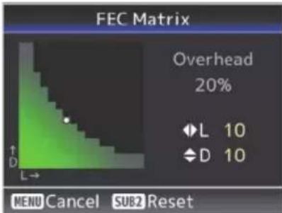
2 Adjust the L and D values.
Use the ◀/▶ buttons to adjust the L value, and the ▲/▼ buttons to adjust the D value.
The amount of FEC overhead changes when the L and D values are changed.
To restore the L and D values to their default values, press the [SUB2] button.
Memo :
- Setting range
• 4 ≤ L ≤ 20 (Default value: L = 10)
• 4 ≤ D ≤ 20 (Default value: D = 10)
• L × D ≦ 100 (Default value: L×D = 10×10)
3 Press the Set button (Set).
The screen returns to the streaming server setting screen.
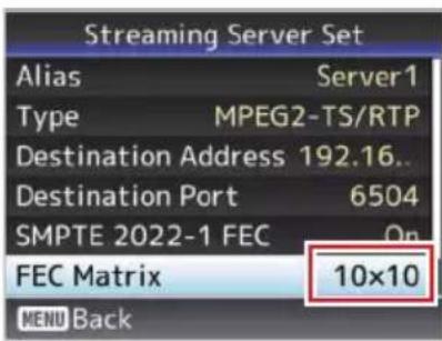
Memo :
- Increasing the amount of FEC overhead increases the packet loss resilience but more network bandwidth is used.
- Even with the same amount of overhead, increasing the L value will increase the packet loss (continuous packet loss) resilience.
Error Messages and Actions
Warning display on the externally-connected display screen or the Live View screen, tally lamp indication and warning tone are displayed or output according to the error status as shown in the table below.
Memo :
- This camera recorder makes use of a microcomputer. Noise interference from external sources may prevent it from functioning properly. When this occurs, turn off and on the power of the camera recorder again.
| Error Message Status Action | ||
| Turn Power Off Turn Back On Later | System error.* The tally lamp blinks twice every second. | Turn off the power, and turn it on again.If the error persists, please contact the local dealers in your area. |
| Media Was Removed. | Card is removed while recording is in progress.Card is removed while formatting is in progress.Card is removed while restoring is in progress.Card is removed while adding the OK mark.Card is removed while writing a setup file.Card is removed while deleting a clip. | Restore the card using this camera recorder.(P28 [Restoring the microSD Card]) |
| Media Full | [REC] button is pressed when the media in use has no remaining space.Remaining space ran out during recording. | Replace the microSD card with a new one. |
| No Media [REC] button is pressed when a microSD card is not inserted. | Insert a microSD card.(P27 [Inserting an microSD Card]) | |
List of FTP Transfer Errors
If the upload of a recorded clip or download of the metadata setup file (XML format) is not successfully completed, the following errors are displayed.
| Error message Status Action | |
| Timeout. Transfer was discontinued due to timeout caused by network transmission or server failure. | Execute again.Use a different server. |
| Media Was Removed. microSD card is removed while FTP transfer is in progress. | Insert the microSD card and execute FTP transfer again. |
| Adapter Was Removed. The USB network device is removed while FTP transfer is in progress. | Connect the USB network device. |
| Cannot Connect to Server. Unable to connect to the FTP server. | Adjust the Server and Port settings for [Metadata Server] or [Clip Server].(P64 [ Metadata Server ] )(P63 [ Clip Server ] ) |

| Error message Status | Action | |
| Access Denied. Access is denied. | ed. Adjust the Server and Port settings for [Metadata Server] or [Clip Server].(P64 [ Metadata Server])(P63 [ Clip Server]) | |
| Invalid Username or Password. | Authentication for login to the FTP server failed. | Adjust the Username and Password settings for [Metadata Server] or [Clip Server].(P64 [ Metadata Server])(P63 [ Clip Server]) |
| Invalid Path Was Requested. | The path specified for the FTP server is incorrect. | Adjust the [Clip Server] and [Dir.Path] settings for [Metadata Server] or [File Path].(P64 [ Metadata Server])(P63 [ Clip Server]) |
| Server Error. There was an unintended operation of the FTP server. | Execute again.Use a different server. | |
| Invalid Request. A bad request is executed for the FTP server. | Execute again. | |
| Invalid Data Size. Invalid data size, such as a planning metadata size that exceeds 4 KB. | Adjust the planning metadata saved in the [Metadata Server].(P80 [ Planning Metadata]) | |
| Invalid Data Format. The XML format of the planning metadata is invalid. | Adjust the planning metadata saved in the [Metadata Server].(P80 [ Planning Metadata]) | |
| Transfer Error. Transfer failed due to communication failure. | Execute again. | |
| Invalid URL. The path was deemed invalid by the FTP server. | Adjust the Server and Port settings for [Metadata Server] or [Clip Server].(P64 [ Metadata Server])(P63 [ Clip Server]) | |
| Media Access Error. Reading/writing of the microSD card failed while FTP transfer is in progress. | Insert a different microSD card. | |
| Internal Error. An internal error has occurred while FTP transfer is in progress. | Adjust the settings and execute again. | |
| Other Error. | An unknown error or other errors have occurred while FTP transfer is in progress. | Adjust the settings and execute again. |
| Media Read Error. | Reading of the microSD card failed while FTP transfer is in progress. | Insert a different microSD card. |
List of Live Streaming Error Displays
The following error messages are displayed when the live streaming setting is incorrect, or when the connection is lost during live streaming.
| Error message Status | Action | |
| Invalid Address | The IP address format is incorrect.The domain name cannot be converted into the IP address. | Enter the IP address, host name or URL of the destination correctly.(P97 [Setting Distribution]) |
| Multicast Is Not Supported An | IP multicast address was set. Use an | IP address that is not a multicast address. |
| Cannot Connect to Receiver E | establishment of connection with TCP failed. | Ensure that the recipient's device is set to TCP.Set Type to "MPEG2-TS/UDP".(P97 [Setting Distribution]) |
| TCP Disconnected TCP connection is lost. Check to ensure that there is no abnormality in the decoder, or network connection device and cables, followed by establishing the connection again. | ||
| Not Enough Bandwidth | The communication bandwidth is narrower than the average bit rate.The network bandwidth is insufficient, and packets are discarded. | Lower the resolution/picture quality of the video to be distributed.Consider switching to the use of a stable network, such as wired LAN. |
| Connection Timeout Timeout for connection via ZIXI. Set [Destination Address] and [Destination Port] correctly.(P97 [Setting Distribution]) | ||
| Authorization Failed Authentication of connection via ZIXI failed. | Set [Stream ID] and [Password] correctly.(P97 [Setting Distribution]) | |
| Connection Error Connection via "ZIXI" or "RTMP" failed. | Check whether a different camera with an identical stream ID is connected.Set [Destination URL] and [Stream Key] correctly.(P61 [ Destination URL ] )(P61 [ Stream Key ]) | |
| Disconnected "ZIXI" or "RTMP" connection is lost. Check whether there is abnormality with the network connection device, cables, etc., and try to re-establish the connection. | ||
| Streaming is unable to reach the destination. | The IP address format is incorrect.The domain name cannot be converted into the IP address.Streaming is unable to reach from the terminal specified in [Interface].The terminal specified in [Interface] is not consistent with the terminal in [Default Gateway] when streaming on a non-local network. | Enter the IP address, host name or URL of the destination correctly.Check and adjust the interface settings.Make sure that the interface settings are consistent with those of the default gateway. |
Blinking of the Tally Lamp
The lamp appears blinking such as when the remaining level of the microSD card is running low, or when a system error occurs on the camera.
* The operation changes according to the menu settings. To configure the setting, go to [Main Menu] →
[System] → [Tally Lamp].
(P66 [ Tally Lamp ] )
| Blinking Mode Description | |
| Blinks slowly (once every second) | Remaining recording time on microSD card is less than 3 minutes (during recording)When a malfunction occurred during live streaming |
| Blinks quickly (2 times per second) | Remaining recording time on microSD card is zero (during recording)Error on the camera recorderWhen an error occurs during control via the controller |
Troubleshooting
| Problem Cause Action | ||
| Power does not turn on. | The AC adapter is not properly connected. | Check whether the AC adapter is properly connected. |
| There is problem in the connection with the PoE+ (IEEE802.3at Type2) power supply device. | · Check whether connection is established using a PoE+ (IEEE802.3at Type2) power supply device and a LAN cable of Category 5e or higher.For some PoE+ power supply devices (such as a hub), power will not be supplied when the number of PoE+ terminals connected exceeds the limit of the total electrical power that can be supplied. For more information, please refer to the instruction manual of the PoE+ power supply device.· Check whether the LAN cable is properly connected and whether the cables are disconnected. | |
| The power was turned on again immediately after it was turned off. | Wait for an interval of at least 5 seconds before turning on the power again. | |
| Unable to operate the infrared remote control unit. | The battery of the infrared remote control unit is not functioning properly. | Check whether there is remaining battery power and whether the battery is loaded in the correct orientation. |
| IR ID is not correctly configured. | Configure IR ID correctly. | |
| There are strong light sources such as a fluorescent light in the surrounding. | Install the camera at a position that is away from light sources such as a fluorescent light. | |
| The adjustable pan/tilt range is narrow. | The pan/tilt limit setting is enabled. | Check the settings in [Pan Right Limit], [Pan Left Limit], [Tilt Up Limit] and [Tilt Down Limit]. |
| Pan/tilt operation moves in the opposite direction. | The method for installing the camera does not match the standing installation settings. | Check whether the standing installation settings are correctly selected. |
| The video images are upside down. | The method for installing the camera does not match the standing installation settings. | Check whether the standing installation settings are correctly selected. |
| Unable to operate the controller and web browser screen. | The LAN cable is not properly connected. | Check whether the LAN cable (Category 5e or higher) is properly connected. |
| The IP address is not correctly configured. | · Check whether the IP address setting is correct.· Configure a different network address (network segment) for the LAN terminal and USB terminal. | |
| [Web Access] in the menu has been set to “Off”. | If you are unable to operate via a web browser, set [Web Access] in the menu to “On”. | |
| The DIP switches at the bottom surface of this unit are not correctly configured. | If you are unable to operate using a controller, check the settings of the DIP switches at the bottom surface of this unit |

| Problem Cause Action | ||
| The View Remote screen turns black.The screen flickers.The screen freezes.Cannot perform remote operation. | The network path is congested. Wait | a while before refreshing (reloading) the web browser or initializing the cache. |
| The View Remote text overflows from the frame. | The font size of the web browser is too big. | Reduce the font size of the web browser. |
| Cannot connect to wireless LAN. | Wireless LAN is not correctly configured. | Check the mode of connection and method of setting ([SSID] and [Passphrase] in cases other than “WPS”). |
| The passphrase is incorrect. Even if | the passphrase is wrong,“Completed the Setup Wizard. Please Input the Passphrase into Your Device.” may appear in the wizard setting depending on the type of encryption.Adjust [Passphrase] again. | |
| Wireless LAN connection is disrupted. | Wireless LAN connection is subject to disruption due to the surrounding environment. | Wireless LAN connection may be disrupted depending on the environment. Change the usage environment. |
| Video images and audio sound during live streaming are choppy or unstable. | The encoding bitrate configured is too high for the transfer speed of the network in use. | Depending on factors such as the type of device connected and the network environment, images and audio sound during live streaming may be choppy.When this occurs, try lowering the bit rate setting. |
| Unable to start recording. | The recording mode is not supported by the microSD card. | Use a microSD card that supports the recording mode. |
| The actual recording time is shorter than the estimated time. | - The recordable time may be shorter | depending on the shooting conditions or the subject. |
| The clips cannot be uploaded to the FTP server. | [Clip Server] is not correctly configured. | Adjust the [Clip Server] settings. |
| The file size is limited by the FTP server settings. | The maximum size of the recorded clip is 64 GB. Set the size limit in the FTP server setting to 64 GB or larger. | |
| An FTP transfer error message is displayed. | Take the necessary actions according to the “List of FTP Transfer Errors”. | |
| No audio sound. The audio menu is set to “Off”. Set the audio menu to “On”. | ||
Specifications
General
| Item Description | |
| Power DC 12 V (when an AC adapter is used)DC 42 V to 57 V (when PoE+ power supply is used) | |
| Current consumption | 1.2 A (*1)0.4 A (*2) |
| Mass Approx. 2.0 kg | |
| Allowable operating temperature | 0 °C to 40 °C (32 °F to 104 °F) |
| Allowable operating humidity | 30 %RH to 80 %RH (No condensation) |
| Allowable storage temperature | -20 °C to 50 °C (-4 °F to 122 °F) |
| Dimensions (W × H × D) | 154 mm × 200.7 mm × 191 mm |
*1 During recording in the factory settings when an AC adapter is in use.
*2 During recording in the factory settings when this unit is operated using power supply from PoE+ via a LAN cable.
Terminal Section
| Item Description | ||
| [SDI OUT] terminal (720p/1080i/1080p: embedded audio), BNC (unbalanced) | ||
| 3G-SDI Compliant with SMPTE ST424 | ||
| HD-SDI Compliant with SMPTE ST292 | ||
| [HDMI] output terminal (Type A) | V1.4-compliant | |
| [LAN(PoE+)] terminal | RJ-45PoE+ power supply: DC 42 V to 57 VEthernet: 100BASE-TX/1000BASE-T | |
| [AUDIO IN] terminal | Φ3.5 mm stereo mini jack | |
| Mic Input Balanced monauralUnbalanced stereo (plug-in power: 2.5 V) | ||
| Line input Balanced monauralUnbalanced stereo | ||
| [RS-422] terminal | RJ-45Input terminal for remote control unit of RS-422 serial control | |
| Item Description | |
| [RS-232C IN] terminal | Mini DIN 8-pinInput terminal for RS-232C remote control unit |
| [RS-232C OUT] terminal | Mini DIN 8-pinOutput terminal for RS-232C remote control unit(Termination function) |
| [DC 12V] terminal | DC jack (for the supplied AC adapter) |
| [USB] terminal | USB-A type, USB2.0, network connection function only |
Lens Section
| Item Description |
| Lens f/1.6 to f/4.7, 30x, f = 4.3 mm to 129.0 mm(35 mm equivalent: 30.5 mm to 915 mm) |
Camera Section
| Item Description | |
| Image pickup device | 1/2.8-inch Progressive CMOS |
| Sync system Internal sync (built-in SSG) | |
| Gain 0dB, 3dB, 6 | dB, 9dB, 12dB, 15dB, 18dB, 21dB, 24dB, 30dB, 36dB, 42dB, 48dB |
| Electronic shutter | 1/8 to 1/10000, 19 steps |
Rotation Mechanism Section
| Item Description | |
| Horizontal rotation range | ±175° |
| Horizontal rotation speed | Maximum 480°/s (AC adapter power)Maximum 400°/s (PoE+ power) |
| Vertical rotation range | -30° to 90° |
| Vertical rotation speed | Maximum 300°/s (AC adapter power)Maximum 200°/s (PoE+ power) |
Storage Section
| Item Description | |
| Supported media | microSDHC/microSDXC |
Video/Audio
| Item Description | ||
| HD mode (QuickTime) | ||
| Recording file format | QuickTime File Format | |
| Video | ||
| 50M mode (LPCM) | MPEG-4 AVC/H.264, 50 Mbps (Max)1920x1080/59.94p, 59.94i, 29.97p, 50p, 50i, 25p | |
| 35M mode (LPCM) | MPEG-4 AVC/H.264, 35 Mbps (Max)1920x1080/59.94i, 29.97p, 50i, 25p1280x720/59.94p, 50p | |
| 28M mode (LPCM) | MPEG-4 AVC/H.264, 28 Mbps (Max)1920x1080/59.94p, 50p | |
| 18M mode (LPCM) | MPEG-4 AVC/H.264, 18 Mbps (Max)1920x1080/59.94i, 29.97p, 50i, 25p1280x720/59.94p, 29.97p, 50p, 25p | |
| 5M mode (μ-law) | MPEG-4 AVC/H.264, 5 Mbps1920x1080/59.94i, 50i1280x720/29.97p, 25p | |
| Audio LPCM 2ch, 48 kHz/16 Bit, μ -law2ch (Video 5 Mbps) | ||
| Streaming Mode (When the [LAN] terminal is connected) | ||
| Video 1920x1080 (59.94p, 50p)20/16/12/8 Mbps1920x1080 (59.94i, 50i,29.97p, 25p)20/16/12/8/5/3 Mbps1280x720 (59.94p, 50p)20/16/12/8/5/3 Mbps1280x720 (29.97p, 25p)8/5/3/1.5 Mbps640x360 (29.97p, 25p)3/1.5/0.8/0.3 Mbps | ||
| Audio AAC 2ch 128 kbps (Video20/16/12/8/5/3/1.5 Mbps)AAC 2ch 64 kbps (Video 0.8/0.3 Mbps) | ||
| Item Description | |
| Streaming Mode (When the [USB] terminal is connected) | |
| Video 1920×1080 (59.94p, 50p) 12/8Mbps1920×1080 (59.94i, 50i, 29.97p, 25p)12/8/5/3 Mbps1280×720 (59.94p, 50p)12/8/5/3 Mbps1280×720 (29.97p, 25p)8/5/3/1.5 Mbps640×360 (29.97p, 25p)3/1.5/0.8/0.3 Mbps | |
| Audio AAC 2ch 128 kbps (Video12/8/5/3/1.5 Mbps)AAC 2ch 64 kbps (Video 0.8/0.3 Mbps) | |
| Live View Mode 640x360320x180 | |
Infrared Remote Control
| Item Description | |
| Remote control system | Infrared type |
| Battery CR2025 | (DC 3.0 V) |
| Battery life Approx | x. 1 year (varies with the frequency of use) |
| Operating distance | 7 m (horizontal distance from the front) |
| Allowable operating temperature | 0 °C to 40 °C (32 °F to 104 °F) |
| Dimensions (W × H × D) | 42 mm × 14.6 mm × 90 mm |
| Mass Approx. 29 | g (including button battery) |
Accessories
| Accessories | |
| Warranty Card (U model only) 1 | |
| INSTRUCTIONS (Installation/IP Address Settings) | 1 |
| AC Adapter 1 | |
| Power Cord (U model: 1, E model: 2) | |
| Remote control unit 1 | |
| Ceiling mount bracket 1 | |
| M3 screw (* for fastening ceiling mount bracket) | 1 |
| M2.6 screw (* for fall prevention wire (camera)) | 1 |
| Fall prevention wire 1 | |
| Template 1 | |
| Dimensional Outline Drawing (Unit: mm)
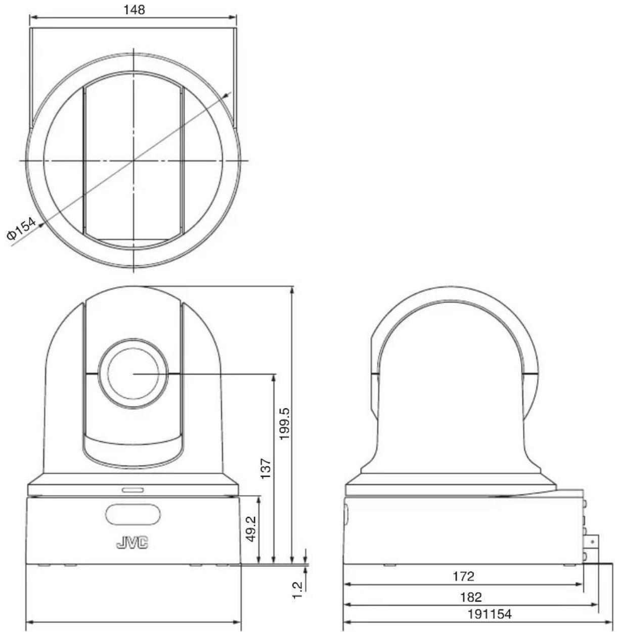
* The specifications and appearance of this product are subject to changes for further improvement without prior notice.
Software License Agreement
The software embedded in the Product (hereinafter the “Licensed Software”) provided by JVC KENWOOD Corporation (hereinafter the “Licensor”) is copyrighted to or sublicensable by the Licensor, and this Agreement provides for the terms and conditions which Users shall follow in order to use the Licensed Software. The User shall use the Licensed Software by agreeing with the terms of this Software License Agreement. This Agreement shall be deemed completed at the time the User (hereinafter the “User”) initially used the Product in which the “Licensed Software” is embedded.
The Licensed Software may include the software which has been licensed to the Licensor directly or indirectly from any third party. In such case, some third parties require the Users to follow their conditions for use separately from this Software License Agreement. Such software shall not be subject to this Agreement, and the Users are urged to read the “Important Notice concerning the Software” to be provided separately.
Article 1 General Provision
The Licensor shall grant to the User a non-exclusive and non-transferable (other than the exceptional case referred to in Article 3, Paragraph 1) licensed to use the Licensed Software within the country of the User (the country where the User bought the Product (hereinafter the “Country”)).
Article 2 License
- The license granted under this Agreement shall be the right to use the Licensed Software in the Product.
- The User shall not duplicate, copy, modify, add, translate or otherwise alter, or lease the Licensed Software and any related documents, whether in whole or in part.
- The use of the Licensed Software shall be limited to personal purpose, and the Licensed Software shall not be distributed, licensed or sub-licensed whether it is for commercial purpose or not.
- The User shall use the Licensed Software according to the directions described in the operation manual or help file, and is prohibited to use or duplicate any data in a manner violating the Copyright Law or any other laws and regulations by applying whole or a part of the Licensed Software.
Article 3 Conditions for Grant of License
- When the User transfers the Product, it may also transfer the license to use the Licensed Software embedded in the Product (including any related materials, updates and upgrades) on condition that no original, copies or related materials continue in the possession of the User, and that the User shall cause the transferee to comply with this Software License Agreement.
- The User shall not carry out reverse engineering, disassembling, decompiling or any other code analysis works in connection with the Licensed Software.
Article 4 Right pertaining to the Licensed Software
- Any and all copyrights and other rights pertaining to the Licensed Software and related documents shall belong to the Licensor or the original holder of the right who granted to the Licensor the license or sublicense for the Licensed Software (hereinafter the “Original Rightholder”), and the User shall not be entitled to any right other than the license granted hereunder, in respect of the Licensed Software and any related documents.
- The User shall, whenever the User uses the Licensed Software, comply with any laws relating to the copyright and other intellectual property rights.
Article 5 Indemnification of Licensor
- Neither the Licensor nor the Original Rightholder shall be liable for any damage incurred by the User or any third party due to the exercise of the license granted to the User under this Agreement, unless otherwise restricted by law.
- The Licensor will offer no guarantee for the merchantability, convertibility and consistency with certain objective of the Licensed Software.
Article 6 Liability to Third Party
If any dispute has arisen with any third party due to an infringement upon a copyright, patent or any other intellectual property right that was caused by the User's use of the Licensed Software, the User shall settle such dispute at the User's own cost and hold the Licensor and the Original Rightholder harmless from any inconvenience it may cause.
Article 7 Confidentiality
The User shall keep the confidentiality of such portion of the Licensed Software, related documents thereof or any other information to be granted under this Agreement, as well as the conditions of this Agreement as has not yet entered the public domain, and shall not disclose or divulge the same to any third party without approval of the Licensor.
Article 8 Termination
In case the User falls under any of the events described in the following items, the Licensor may immediately terminate this Agreement or claim that the User compensates for the damage incurred by the Licensor due to such event:
(1) when the User violated any provision of this Agreement; or
(2) when a petition has been filed against the User for an attachment, provisional attachment, provisional disposition or any other compulsory execution.
Article 9 Destruction of the Licensed Software
If this Agreement is terminated pursuant to the provision of Article 8, the User shall destroy the Licensed Software, any related documents and copies thereof within two (2) weeks from such date of termination.
Article 10 Export Restriction
- The User shall understand that the Licensed Software shall be subject to the export restrictions adopted by the country of User and any other countries.
- The User shall agree that the software will be subject to any and all applicable international and domestic laws including the export control regulation of the country of User and any other countries, and any restrictions concerning the end-users, the use by end-users and importing countries to be provided by the country of User and any other countries, and any other governmental authorities.
- If the User is an agency of the United States of America (the “Government”), the User acknowledge Licensor’s representation that the Licensed Software is a “Commercial Item” as defined in Federal Acquisition Regulation (FAR) part 2.101(g) consisting unpublished “Commercial Computer Software” as those items are used at FAR part 12.212 and is only license the User with the same use right Licensor grants all commercial end users pursuant to the terms of this Agreement.
Article 11 Miscellaneous
- In the event any part of this Agreement is invalidated by operation of law, the residual provisions shall continue in force.
- Matters not stipulated in this Agreement or any ambiguity or question raised in the construction of this Agreement shall be provided or settled upon good-faith consultation between the Licensor and the User.
- The Licensor and the User hereby agree that this Agreement is governed by the laws of Japan, and any dispute arising from, and relating to the rights and obligations under, this Agreement shall be submitted to the exclusive jurisdiction of the Tokyo District Court for its first instance.
Important Notice concerning the Software
Software License Attached to the Product :
The Software embedded in the Product is composed of several independent software components, and in each of such individual components (hereinafter the “Licensed Software”), a copyright of either JVC KENWOOD Corporation (hereinafter “JKC”) or a third party subsists.
The Product uses the software component designated in the End-User License Agreement that was executed between JKC and a third party (hereinafter “EULA”).
The Licensed Software covers those corresponding to free software, and, as a condition of distribution of the software component in executable format which is based on the license granted under the GNU General Public License or Lesser General Public License (hereinafter "GPL/LGPL"), it requires an availability of the source code for the relevant component. Please refer to the following URL concerning the distribution of the source code;
http://www3.jvckenwood.com/english/download/gpl/index.html
Please note that we are unable to answer any inquiry relating to the contents, etc. of the source code. In addition, the Licensed Software includes the software developed or created independently by JKC and there exists an ownership of JKC in such software and any accompanying documents, which is protected by the Copyright Law, any international treaties and other applicable laws. As to matters concerning the handling by JKC of the software components, please refer to the “Software License Agreement” attached hereto.
Please note that any software component licensed under “EULA” which is not subject to “GPL/LGPL”, and those developed or created independently by JKC shall not be subject to the requirement for provision of the source code. The software component distributed under “GPL/LGPL” shall be licensed to users without charge, and, therefore, no warranty is given for such software component, either express or implied, within the scope of the applicable laws and regulations. Unless otherwise permitted by applicable laws and regulations or agreed in written form, none of the owners of the copyright or persons entitled to alter or redistribute the software component under the said license shall have any liability for any type of damage or loss resulting from the use of or inability to use such software component. For further details of the conditions of use of such software component or matters required to be complied with, please refer to the relevant “GPL/LGPL”.
Users are urged to read the details for the relevant license carefully before using the software component covered by “GPL/LGPL” and embedded in the Product. Since the terms and conditions of individual licenses are provided by parties other than JKC, the original English version will be displayed by the Product.
① Start up Live View.
② Open the [MENU] tab and click the [MENU] button to display the camera menu.
③ Select [Main Menu] → [System] → [System Information] → [Open Source License].
Index
A AC adapter 33
Access point 76
AWB paint 45
B Brightness adjustment 41
C Camera mode 19, 26, 69
Cellular adapter 78
Clip name 29,68
Color bar 56
Computer 35
Connection settings file 93
D Date/Time 66
Deleting clips 85
Digital Zoom 40,56
Display screen 26, 69
E Error message 101
Exposure 36, 41, 55
External monitor 73
F FEC matrix 62,100
Focus 41
Formatting (initializing) microSD cards ..... 28
FTP server 78, 83, 101
G Gain adjustment 43
I Image Stabilizer 46
IP Address 34, 88, 89
Iris adjustment 42
L Live streaming 97
Loop Recording 51,68
M Maintenance Mode 19, 26, 96
Menu Screen 52, 54
Metadata 78,80
microSD/microSDHC/microSDXC card 15, 27
N Network 34,74
Network operating environment 74
O One push auto focus 41
P P2P 76
Pan/Tilt 22, 36, 40, 57
Picture quality setting 46
Preset mode 39
R Recordable time 27
Remote edit mode 19,26
Resolution 38
Restoring microSD card 28
S SDI 59,73
Setup file 96
Shooting 38
Skin detail function 56
Software keyboard 53
Status screen 26,72
Switching shutter mode 44
T Tally lamp 25,104
Time code 47, 48
Time code generator 48
U User's bit 50
V Video Off Mode 19,26
View remote 26,36
W Warning 26,105
Web browser 35,87
White balance adjustment 45
Wireless LAN 76
Z Zoom 40

JVC

- KY-PZ100WU/KY-PZ100WE KY-PZ100BU/KY-PZ100BE
- INSTRUCTIONS
- About the latest INSTRUCTIONS
- For Customer Use:
- Please read the following before getting started:
- FOR USA
- IMPORTANT SAFEGUARDS
- CAN ICES-3 A / NMB-3 A
- For USA-California Only
- Safety Precautions
- FOR USA AND CANADA
- CAUTION
- CAUTION:
- POUR CANADA
- ATTENTION
- ATTENTION:
- WARNING:
- NOTES:
- REMARQUES :
- Caution on Replaceable lithium battery
- CAUTION!
- When using the AC adapter in areas other than the USA
- USING HOUSEHOLD AC PLUG ADAPTER
- IMPORTANT (for owners in the U.K.) Connection to the mains supply in the United Kingdom.
- DO NOT cut off the mains plug from this equipment.
- CAUTIONS:
- FOR EUROPE
- WARNING
- Dear Customer
- 关于环保使用期限
- Mounting to a firm place
- Mount the camera correctly
- Using the correct power and voltage
- Inspect the unit regularly
- Contents
- Getting Started
- Installation/Connection
- Using View Remote
- Shooting
- Menu Display and Detailed Settings
- Display/Status Screen
- Connecting External Devices
- Connecting to the Network
- Others
- Content of this Manual
- Main Features
- Enhanced network functions
- Supports simultaneous output of 1080/60p SDI, HDMI and live streaming
- Silent PTZ (pan/tilt/zoom) operation
- Highly precise in recalling preset positions
- Compatible with PoE+ power supply for each installation
- 1/2.8-inch high-performance CMOS sensor
- 30x optical zoom lens
- High-quality in-camera recording (microSD)
- Equipped with an audio input terminal
- Comes with ceiling mounting bracket and infrared remote controller
- Supports different types of remote protocols
- Precautions
- Installation Location
- Storage and Usage Locations
- Transportation
- | Carrying the Camera
- Power Saving
- Maintenance
- microSDHC/microSDXC Cards
- Handling of microSD Cards
- Encryption in Network Connection
- License Notices
- Copyright
- Login Password
- Operation Modes
- Names of Parts
- Bottom Section
- | Ceiling mount bracket
- | Terminal Section
- Infrared Remote Control
- DIP Switch Setting
- Tally Lamp
- Memo :
- View Remote (Live View) Screen and External Monitor Connection Display
- Display Screen in Camera Mode
- Status Screen
- Remote Edit Mode Screen
- Maintenance Mode Screen
- | Warning Display
- | Video Off Mode Screen
- About microSD Cards
- | Compatible microSD Cards
- Caution :
- Estimated Recordable Time of microSD Cards
- Inserting an microSD Card
- Removing the microSD Card
- | Formatting (Initializing) microSD Cards
- Formatting is complete.
- Restoring the microSD Card
- | Clips Recorded to microSD Cards
- Folders in the microSD Card
- Clip (Recorded Data) and Clip Name
- ABCG0001
- Recorded Clips
- Mounting the Camera to the Ceiling Mount Bracket
- Fix the fall prevention wire (camera) to the ceiling mount bracket using the screw (M2.6) provided.
- Place the supplied template against the ceiling, and fasten the ceiling mount bracket with four screws (M4 wooden screws: Φ4.1).
- Installing the Camera on the Ceiling
- Set the DIP switch.
- Insert an microSD card.
- Attach the fall prevention wire (camera), which is fixed to the ceiling mount bracket, to the camera.
- Mount the camera to the ceiling mount bracket.
- Fix the camera and the fall prevention wire (ceiling) on the ceiling mount bracket using the provided screw (M3).
- Connect the adapter to the [USB] terminal.
- Installing the Camera on a Desktop
- Attaching the Camera to a Tripod
- Connecting the Cables
- Connect the power cable.
- Remove the protective sheet attached to the infrared remote control sensor.
- IP Address Settings
- Using the IP Setting Tool
- Click the [Close] button to exit.
- Configuring IP Address Manually
- Confirming the Connection
- Start up the web browser on the terminal you wish to connect to the camera recorder, and enter the IP Address in the address field.
- Enter the user name and password.
- View Remote Screen
- Basic Shooting Procedures
- Preparations
- Selecting Video Recording Resolution, Frame Rate and Bit Rate
- Selecting a System Definition
- Select a frame rate
- Select a bitrate
- Preset Mode
- Storing/Recalling the Current Preset Information
- Save the preset information.
- Enter a [Preset] number button and press the [Store] button.
- Recall the stored preset number.
- Pan/Tilt Operation
- Zoom Operation
- Focus Operation
- Adjusting Focus Automatically
- Press the [Auto] button under the [Focus] tab on the browser (Live View) screen.
- One Push Auto Focus
- Adjusting Focus Manually
- Press the [Manual] button under the [Focus] tab on the browser (Live View) screen.
- Press the focus control button to adjust focus.
- Adjusting the Brightness
- Adjusting the Brightness Automatically: Automatic Brightness Adjustment (AE) Mode
- Set the target level (brighter/darker) to maintain optimum brightness during automatic adjustment.
- Adjusting the Brightness Manually
- Adjusting the Iris
- | Auto Iris (Automatic Adjustment) Mode
- Set [Exposure] to "Auto" or "Shutter".
- Manual Iris (Manual Adjustment) Mode
- Set [Exposure] to "Iris" or "Manual".
- Press the iris adjustment button to adjust the iris manually.
- About the Iris F-number
- Setting the Gain
- Automatic Gain Mode (Automatic Gain Adjustment)
- Set [Exposure] to "Auto".
- Manual Gain Mode (Manual Gain Switching)
- Setting the Electronic Shutter
- Automatic Shutter Mode (Automatic Shutter Adjustment)
- Set [Exposure] to "Auto" or "Iris".
- Manual Shutter Mode (Manual Shutter Switching)
- Set [Exposure] to "Shutter" or "Manual".
- Press the shutter adjustment button to adjust the shutter speed.
- Adjusting the White Balance
- Automatic White Balance Mode (FAW: Fulltime Auto White balance)
- Set the [White Balance] mode selection button to "FAW".
- AWB Mode
- AWB Paint Adjustment
- Adjust the R and B values.
- Manual White Balance Mode (Manual Switching)
- Adjusting the Camera Image
- Using the Image Stabilizer
- Audio Recording
- | Recording Audio Sound
- Selecting the Audio Sound to Record
- | Setting the Audio Gain
- Time Code and User's Bit
- Displaying Time Code and User's Bit
- Make a selection from [Main Menu] → [System] → [Information Display] → [TC/UB]. (P65 [TC/UB])
- Time Code Operation Mode
- Setting Time Code Generator
- | Presetting the Time Code
- Required Settings Before Preset
- Set [TC/UB] → [TC Generator] to "Rec Run" or "Free Run".
- Select the framing mode for the time code generator (only when the frame rate setting is "60" or "30").
- Setting Time Code
- Select [Main Menu] → [TC/UB] → [TC Preset] and press the Set button (Set).
- Set the time code (hour, minute, second, frame).
- Check the values and press the Set button (Set).
- Press the [Back] button.
- Recording Time Code in Continuation of the Recorded Time Code on microSD Card
- Set [TC/UB] → [TC Generator] to "Regen".
- Setting the User's Bit
- | Selecting a Recording Mode
- Recording date/time information to the user's bit
- Set [Main Menu] → [TC/UB] → [UB Mode] to "Date" or "Time", and press the Set button (Set).
- | Presetting the User's Bit
- Recording arbitrary information (8-digit hexadecimal) to the user's bit
- Set [Main Menu] → [TC/UB] → [UB Mode] to "Preset", and press the Set button (Set).
- Loop Recording
- Basic Operations in Menu Screen
- Displaying the Menu Screen
- Display and Description of the Menu Screen
- | Text Input with Software Keyboard
- Entering a subname
- Entering the [Clip Name Prefix]
- Settings under [Network] → [Settings]
- Menu Screen Hierarchical Chart
- Camera Function Menu
- Image Stabilizer
- Exposure
- AE Speed
- AE Level
- Slow Shutter
- AGC Limit
- Gain
- Shutter
- Iris (Wide)
- Night Mode
- Defog
- Digital Zoom
- Focus Mode
- AF Speed
- Bars
- Camera Process Menu
- Detail
- High Sensitivity
- NR
- WDR
- White Balance
- → AWB Paint
- → R/B Gain
- Color Gain
- Color Phase
- Reset Process Settings
- Pan/Tilt Menu
- Pan/Tilt Preset Speed
- Ramp Curve
- Speed With Zoom
- Freeze during Preset
- Pan Right Limit/Pan Left Limit
- Tilt Up Limit/Tilt Down Limit
- TC/UB Menu
- TC Generator
- TC Preset
- UB Mode
- → Preset
- Drop Frame
- A/V Set Menu
- Video Set...
- Audio Set...
- Video Set Item
- HDMI/SDI Out
- → Resolution
- HDMI Color
- → HDMI Enhance
- → HDMI TC
- 3G-SDI Mapping
- Audio Set Item
- Audio
- Input Mode
- Input Select
- Audio Gain
- Equalizer
- Test Tone
- Network Menu
- Connection Setup
- → LAN Wizard
- → USB Wizard
- Load
- → Store
- → Delete
- → Default Gateway
- → FTP Proxy
- → APN
- Web
- → Web Access
- → Camera Name
- → Login Name (Fixed)
- Live Streaming Set
- Live Streaming
- → Interface
- → Server
- → Streaming Server
- → Server1/Server2/Server3/Server4
- Alias
- Type
- ■ Destination Address
- ■ Destination URL
- ■ Destination Port
- Stream ID
- Stream Key
- → Frame Rate
- → Bit Rate
- Clip Server
- Protocol
- Server
- Port
- Dir. Path
- Username
- ■ Password
- ■ PASV Mode
- Metadata Server
- → Import Metadata
- Reset Network Settings
- System Menu
- System Mode
- Record Set...
- Media
- → Format Media
- → Restore Media
- Information Display
- → Output
- → Zoom
- TC/UB
- Date Style
- Time Style
- IR ID
- Brightness
- Language
- Reset All
- Date/Time
- Time Zone
- Install Position
- System Information
- → Version
- → DIP SW
- → Open Source License
- Record Set Item
- Loop Rec
- 4GB File Spanning(SDXC)
- LPCM
- Time Stamp
- Clip Set
- → Clip Name Prefix
- → Reset Clip Number
- Clear Planning Metadata
- UBFF EE DD 20
- LAN Screen
- USB Screen
- Live Streaming Screen
- Planning Metadata Screen
- Connecting External Monitor
- Connecting via SDI
- Functions of Network Connection
- List of Functions
- View Remote
- Importing Metadata
- Uploading Recorded Clips
- Deleting Recorded Clips
- Editing Metadata
- Loading and Saving Setup Files
- Firmware Update
- Changing Network Connection Settings
- Network Connection
- | Operating Environment
- Computer
- Connecting to Network via [LAN] Terminal
- Connecting to Network via [USB] Terminal
- | Connecting via Wireless LAN (USB)
- Connection via Access Point
- P2P Connection
- From the list of PC access points, select [SSID] and enter [Passphrase].
- Setting is complete.
- Connecting via Ethernet Adapter (USB)
- Connect the Ethernet adapter that is connected to the [USB] terminal of the camera to the PC using a LAN cable.
- Perform setting on the camera recorder, and start up the [Wizard] screen.
- [Ethernet] appears on the [Wizard] screen.
- Press the ▶ button to display the [IP Address Configuration] screen.
- | Connecting via Cellular Adapter (USB)
- Preparing Metadata
- Configuring the Server for Downloading
- Open the [Metadata Server] screen.
- Register the [Metadata Server].
- | Importing Metadata
- Select [Main Menu] → [Network] → [Import Metadata] and press the Set button (Set).
- Select the server for importing the metadata.
- Select [Import] on the confirmation screen, and press the Set button (Set).
- Planning Metadata
- Display the web setting screen.
- Click the [Planning Metadata] button to open the [Planning Metadata] screen.
- Edit the metadata.
- Click [OK] on the confirmation screen.
- | Clip Metadata
- Display the clip list.
- Set the camera recorder to the "Remote Edit Mode".
- Select the Metadata Edit mode.
- Select the clip to rewrite the metadata.
- Edit the metadata of the selected clips.
- Click [OK] on the confirmation screen.
- Uploading a Recorded Video Clip
- Configuring the FTP Server for Uploading
- | Uploading Video Clips
- Select the clip server and start uploading.
- Upload is complete.
- Select the selection mode.
- Select the clips you want to delete.
- Choose a delete action.
- Select a way to delete the clips.
- Start clip deletion.
- Deletion is complete.
- Changing Settings
- Changing Common LAN/USB Connection Settings
- | Changing LAN Connection Settings
- | Changing USB Connection Settings
- | Changing Metadata Server Settings
- ① Server
- ② Alias
- Protocol
- Server
- Port
- ⑥ File Path
- ⑦ Username
- Password
- Passive Mode
- ⑩ [Save]/[Cancel] Button
- | Changing Clip Server Settings
- | Changing Live Streaming Settings
- Managing the Network Connection Settings File
- Number of Storable Setup Files
- | Saving the Connection Settings File
- Name the file.
- Save the file.
- Saving is complete.
- | Reading the Connection Settings File
- | Deleting Connection Settings
- Loading (Uploading) Setup Files
- Press the [Setup File] button.
- Press the [Choose File] button to select the setup file to upload.
- Press the [Upload] button to start uploading of the file.
- Press the [OK] button.
- Press the [OK] button.
- Saving (Downloading) Setup Files
- Press the [Download] button to start downloading of the file.
- Performing Live Streaming
- | Supported Formats
- Video
- | Supported Protocols
- | Setting Distribution
- [Live Streaming Set] Combinations that Support Distribution
- ■ LAN terminal
- USB terminal
- Starting Distribution
- Perform the necessary setting for the decoder and PC application.
- With the network connection established, set [Live Streaming] to "On".
- Setting the FEC Matrix
- Error Messages and Actions
- List of FTP Transfer Errors
- List of Live Streaming Error Displays
- Blinking of the Tally Lamp
- Specifications
- Software License Agreement
- Article 1 General Provision
- Article 2 License
- Article 3 Conditions for Grant of License
- Article 4 Right pertaining to the Licensed Software
- Article 5 Indemnification of Licensor
- Article 6 Liability to Third Party
- Article 7 Confidentiality
- Article 8 Termination
- Article 9 Destruction of the Licensed Software
- Article 10 Export Restriction
- Article 11 Miscellaneous
- Important Notice concerning the Software
- Software License Attached to the Product :
- Index
- JVC
Brand : JVC
Model : KY-PZ100
Category : Camera