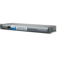
MultiView 4 HD - Processor Blackmagic Design - Free user manual and instructions
Find the device manual for free MultiView 4 HD Blackmagic Design in PDF.


User questions about MultiView 4 HD Blackmagic Design
0 question about this device. Answer the ones you know or ask your own.
Ask a new question about this device
Download the instructions for your Processor in PDF format for free! Find your manual MultiView 4 HD - Blackmagic Design and take your electronic device back in hand. On this page are published all the documents necessary for the use of your device. MultiView 4 HD by Blackmagic Design.
USER MANUAL MultiView 4 HD Blackmagic Design
text_image
Blackmagicdesign TRAVEL LATEST News24.com SportsZone 1 SportsZone 2 Family SportsZone 3 Severe Rainfall Newark USA Travel Challenge News24 National PICKY NEWS24.COM SportsZone 4 EsportsZone 5 EsportsZone 6 EsportsZone 7 EsportsZone 8 EsportsZone 9 EsportsZone 10 EsportsZone 11 EsportsZone 12 EsportsZone 13 EsportsZone 14 EsportsZone 15 EsportsZone 16 EsportsZone 17 EsportsZone 18 EsportsZone 19 EsportsZone 20 EsportsZone 21 EsportsZone 22 EsportsZone 23 EsportsZone 24 EsportsZone 25 EsportsZone 26 EsportsZone 27 EsportsZone 28 EsportsZone 29 EsportsZone 30 EsportsZone 31 EsportsZone 32 EsportsZone 33 EsportsZone 34 EsportsZone 35 EsportsZone 36 EsportsZone 37 EsportsZone 38 EsportsZone 39 EsportsZone 40 EsportsZone 41 EsportsZone 42 EsportsZone 43 EsportsZone 44 EsportsZone 45 EsportsZone 46 EsportsZone 47 EsportsZone 48 EsportsZone 49 EsportsZone 50 EsportsZone 51 EsportsZone 52 EsportsZone 53 EsportsZone 54 EsportsZone 55 EsportsZone 56 EsportsZone 57 EsportsZone 58 EsportsZone 59 EsportsZone 60 EsportsZone 61 EsportsZone 62 EsportsZone 63 EsportsZone 64 EsportsZone 65 EsportsZone 66 EsportsZone 67 EsportsZone 68 EsportsZone 69 EsportsZone 70 EsportsZone 71 EsportsZone 72 EsportsZone 73 EsportsZone 74 EsportsZone 75 EsportsZone 76 EsportsZone 77 EsportsZone 78 EsportsZone 79 EsportsZone 80 EsportsZone 81 EsportsZone 82 EsportsZone 83 EsportsZone 84 EsportsZone 85 EsportsZone 86 EsportsZone 87 EsportsZone 88 EsportsZone 89 EsportsZone 90 EsportsZone 91 EsportsZone 92 EsportsZone 93 EsportsZone 94 EsportsZone 95 EsportsZone 96 EsportsZone 97 EsportsZone 98 EsportsZone 99 EsportsZone 100Installation and Operation Manual
Blackmagic MultiView
June 2018
English, 日本語, Français, Deutsch, Español, 中文, 한국어, Русский, Italiano, Português and Türkçe.

natural_image
Circular portrait photo of a smiling man in a black shirt against a gray background (no text or symbols)Welcome
Thank you for purchasing Blackmagic MultiView!
We hope you share our dream for the television industry to become truly creative by allowing anyone to have access to the highest quality video. By using MultiView 16 with today's affordable Ultra HD televisions, you get the equivalent of up to 16 independent broadcast monitors. MultiView 16 gives you true broadcast level multi source monitoring at a fraction of the cost!
Blackmagic MultiView 4 is perfect for smaller or mobile productions, letting you monitor up to four sources on a HD or Ultra HD screen. You can even combine MultiViews by routing the output of one MultiView into another to really customise your monitoring setup!
This instruction manual contains all the information you'll need to install your Blackmagic MultiView, although it's always a good idea to ask a technical assistant for help if you are not sure what IP addresses are, or if you're unsure about computer networks. Blackmagic MultiView can be controlled using Videohub Control software which is easy to install, however there are a few slightly technical preferences you will need to set after you install it.
Please check our web site at www.blackmagicdesign.com and visit the support page to download the latest updates to this manual and software. Lastly, please register your Blackmagic MultiView when downloading software updates so we can keep you updated when new software is released. We are constantly working on new features and improvements, so we would love to hear from you!
We hope you get years of use from your Blackmagic MultiView and have lots of fun viewing your video inputs in wonderful Ultra HD!
Grant Petty
Grant Petty
CEO Blackmagic Design
Contents
Blackmagic MultiView
Getting Started 5
Plugging in Power 5
Connecting SDI Sources and Monitors 5
Setting your Multi View Layout 6
Connecting to a Network 8
Connecting Serial Control 8
Rack Installation 8
Using Multiple MultiViews 9
Changing Settings 9
Blackmagic MultiView 16's Front Control Panel 10
Teranex Mini Smart Panel 15
Installing Teranex Mini Smart Panel 15
Teranex Mini Smart Panel Features 16
Control Buttons and Rotary Knob 16
Changing Settings using Teranex Mini Smart Panel 17
Changing Settings using Switches 19
Built in Switches 19
Switch Settings for Blackmagic MultiView 4 20
Switch Settings for Blackmagic MultiView 4 HD 21
Using Blackmagic MultiView Setup 23
Installing Blackmagic MultiView Setup 23
Blackmagic MultiView Setup Home Page 24
Changing Settings using Blackmagic MultiView Setup 24
Sources 25
Views 26
Video Output 27
Configure 30
Saving and Loading Label Sets 31
Updating the Internal Software 32
Using Videohub Control Software 33
Developer Information 35
Blackmagic Videohub Ethernet Protocol v2.3 35
Blackmagic MultiView 16 RS-422 Protocol 38
Help 42
Regulatory Notices and Safety Information 43
Warranty 44
Getting Started
Getting started with your Blackmagic MultiView is as easy as plugging in power, connecting your SDI video sources, and plugging your monitors and televisions into the HDMI or SDI outputs. This section of the manual will show you everything you need to know to get started using your Blackmagic MultiView.
Plugging in Power
To power your Blackmagic MultiView, simply plug a standard IEC power cord into the 110-240V AC power input on the rear panel.
TIP Blackmagic MultiView 4 can also accept Power over Ethernet Plus, which means you only need to plug it into an Ethernet switch capable of supplying PoE+. If you have both AC power and PoE+ connected to your MultiView 4, it will automatically switch to the remaining power supply if one is unplugged or fails.
To power Blackmagic MultiView 4 HD, plug the supplied power adapter into the 6-36 V DC input. A screw thread housing is provided so you can secure power to the unit and prevent accidental disconnection.
Connecting SDI Sources and Monitors
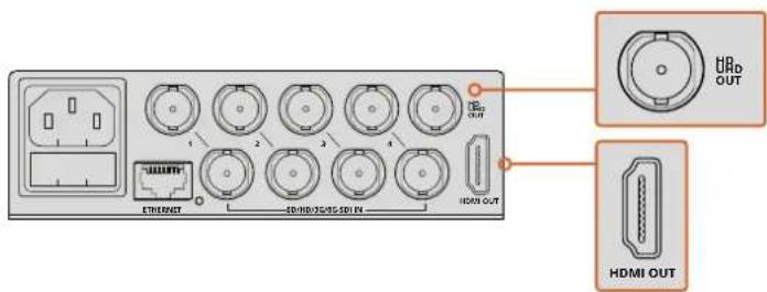
Plug your SDI sources into any of your Blackmagic MultiView's SDI video inputs. The video format will be automatically detected and the video will be displayed in the multi view output. To see the output, simply connect a monitor to the SDI or HDMI multi view outputs.

text_image
1 2 3 4 SD/HD/3G/6G-SDI IN 1 2 3 4 DINJINT 10/80/3G/6G-SDI IN H200 OUTConnect the video sources to your Blackmagic MultiView's SDI video inputs
text_image
U/Rb OUT 1 2 3 4 E:\WINDOWS\50\50\50\IN- HDMI OUT HDMI OUTConnect monitors to your Blackmagic MultiView's HDMI or SDI multi view outputs
When connecting an HDMI monitor to the HDMI output, your Blackmagic MultiView will automatically detect whether the monitor supports Ultra HD or HD and switch the multi view output accordingly.
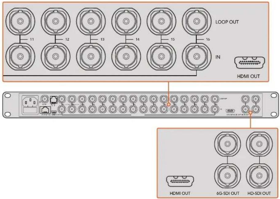
TIP On Blackmagic MultiView 16 you can output the multi view via dedicated HD-SDI outputs, or up to Ultra HD via the 6G-SDI and HDMI outputs.
Blackmagic MultiView 4 and MultiView 16 has loop outputs above each input so you can also connect each source to other video equipment.
text_image
LOOP OUT IN HDMI OUT 11 12 13 14 15 16 HDMI OUT 6G-SDI OUT HD-SDI OUTTIP All of Blackmagic MultiView 16's SDI and HDMI outputs can be used simultaneously for Ultra HD and HD multi view monitoring. On Blackmagic MultiView 4, you can select between Ultra HD or HD multi view output settings using the built in switches, an optional Teranex Mini Smart Panel, or via the Blackmagic MultiView Setup utility software.
Setting your Multi View Layout
The multi view layout can be changed to suit your needs. For example, Blackmagic MultiView 4 and Blackmagic MultiView 4 HD can be set to 2x2 or solo. Blackmagic MultiView 16 can be set to a combination of views such as 2x2, 3x3, 4x4 or solo.
Setting your layout on Blackmagic MultiView 16
To change the layout on Blackmagic MultiView 16, use the control buttons, rotary knob and LCD on the built in control panel. You can also monitor any view in full screen mode by pressing the 'solo' button, then selecting your chosen input by pressing one of the source buttons.
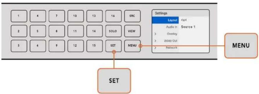
1 Press the 'menu' button on the front control panel to open the settings screen on the LCD.
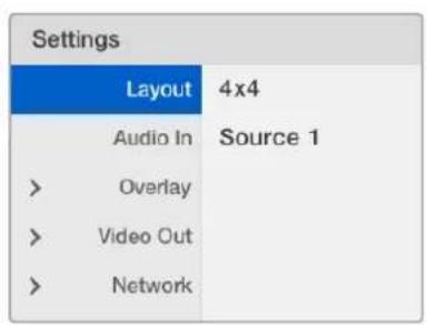
2 Layout is the first setting in the menu, so it is always highlighted when you first enter the settings menu. Press the 'set' button to edit the setting.
3 Select 4x4 from the layout setting by turning the rotary knob on the front control panel. 4x4 lets you see all 16 source views on one screen. Whenever a setting changes, you'll notice the 'set' button and the 'menu' button will start flashing. This means a setting has changed and you can either confirm the setting change by pressing the 'set' button, or cancel by pressing the 'menu' button.
4 Press the set button to confirm your setting.
You can also set the layout using the Blackmagic MultiView 16 setup software using the configure control panel.
flowchart
graph TD
    A["SET"] --> B["1"]
    A --> C["2"]
    A --> D["3"]
    B --> E["4"]
    B --> F["5"]
    B --> G["6"]
    C --> H["7"]
    C --> I["8"]
    C --> J["9"]
    C --> K["10"]
    C --> L["11"]
    C --> M["12"]
    C --> N["13"]
    C --> O["14"]
    C --> P["15"]
    C --> Q["16"]
    C --> R["SRC"]
    C --> S["SOLO"]
    C --> T["VIEW"]
    C --> U["SET"]
    C --> V["MENU"]
    W["Settings"] --> X["Layout 4x4"]
    X --> Y["Audio in Source 1"]
    Y --> Z["Overlay"]
    Y --> AA["Video Out"]
    Y --> AB["Network"]
To set your Blackmagic MultiView 16's view layout, press 'menu', select your layout using the rotary knob, then press 'set'. 4x4 lets you see all 16 views on one monitor
Setting your layout on Blackmagic MultiView 4
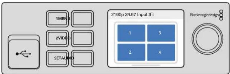
The default view on your Blackmagic Multiview 4 is the 2x2 layout. To change the layout on your Blackmagic MultiView 4 to 'solo', use the control button marked as '1' on your Teranex Mini Smart Panel and press button '2' to change it back to 2x2 display mode.
You can also set the layout using the 'configure' settings in the setup software.
text_image
1MENU 2VIDEO SETAUDIO 2160p 29.97 Input 3 > Blackmagicdesign 1 3 2 4Press '1' for solo view or press '2' for 2x2 view
Setting your layout on Blackmagic MultiView 4 HD
The first time you use your MultiView 4 HD, it defaults to a 2x2 layout with inputs 1 and 3 on the top row and inputs 2 and 4 across the bottom. To change to solo mode, set the built in switch 6 'Solo on' to ON.
| 1 | 3 |
| 2 | 4 |
MultiView 4 HD 2x2 layout of four SDI inputs.
Refer to the 'Switch Settings for Blackmagic MultiView 4 HD' section for more information.
Connecting to a Network
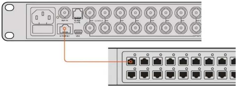
Your Blackmagic MultiView supports the Blackmagic Videohub Ethernet Protocol so if your unit is installed in a rack with limited access, you can easily control it remotely using a Blackmagic Videohub control panel, such as Blackmagic Smart Control and Master Control. Once connected to your network via Ethernet, your Blackmagic MultiView will be visible to other computers and Videohub panels connected to the network. These devices can then control the unit remotely.
To connect Blackmagic MultiView to your network:
1 Power your Blackmagic MultiView
2 Use a standard RJ45 Ethernet cable to connect your Blackmagic MultiView to a network or computer.
Once you have connected to a network, you'll need to make sure your Blackmagic MultiView's IP address is different to the other equipment on your network. On Blackmagic MultiView 16 and when using MultiView 4 with a Teranex Mini Smart Panel installed, you can change the network settings via the control panel's LCD menu. You can also plug your Blackmagic MultiView into a computer via USB and change network settings using Blackmagic MultiView Setup. For more information on changing network settings refer to the 'changing settings' section in this manual.
Connecting Serial Control
Third party router controllers can control Blackmagic MultiView 16 using the RS-422 serial connection. For more information on serial control, see the section 'changing settings using Blackmagic MultiView Setup' in this manual.
Rack Installation
Blackmagic MultiView 16 is 1 rack unit high so fits perfectly into any broadcast rack or road case.
Blackmagic MultiView 4 is much smaller and can be used in mobile productions where you may not be using a broadcast rack. However, even though your MultiView 4 is designed to be small and portable, you can still use it in a rack environment. The Blackmagic Teranex Mini Rack Shelf is designed to let you mount up to three units side by side in a 1 rack unit space so you can easily connect them to each other and build as many source views as you need.
Installing Blackmagic MultiView 4 into a Teranex Mini Rack Shelf is as easy as removing the unit's rubber feet, if installed, and screwing the unit into the base of the shelf using the mounting holes on the bottom. The Teranex Mini Rack Shelf ships with two original blank panels which you can use to cover gaps if you don't need to install additional MultiView 4's.
For more information check the Blackmagic Design website at www.blackmagicdesign.com
When installed in the rack shelf, all connectors are accessed from the rear of the unit as normal.

natural_image
Illustration of a blackmagic MultiView 4 device with ventilation slots and connectors (no text or symbols on the device itself)Using Multiple MultiViews
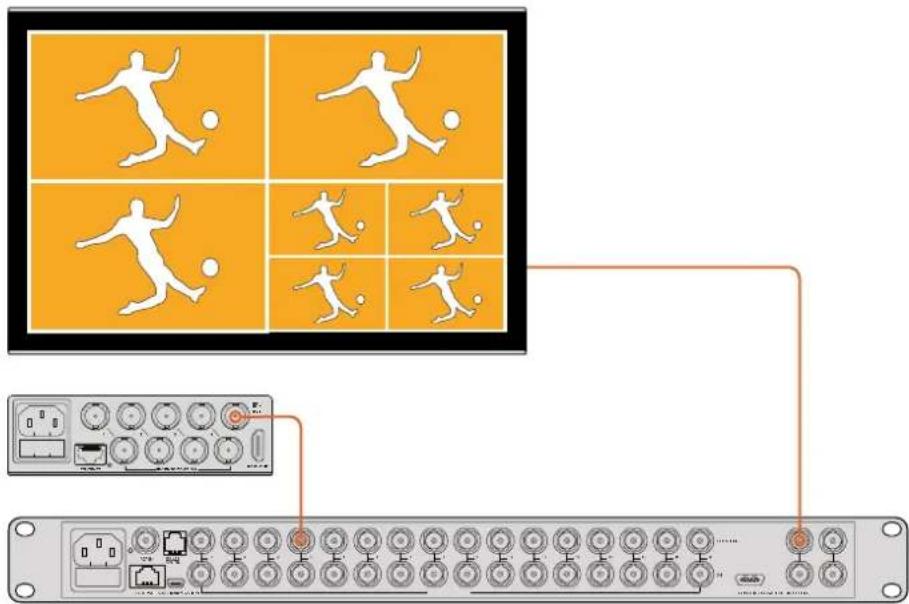
You can use multiple BlackMagic MultiViews in combination to create custom monitoring setups. This is helpful if you need to add more view sources to your multi view output. Simply plug the output from one MultiView into the input of another to add more source views to your multi view output. It is highly recommend that the upstream multi view output is connected to an Ultra HD monitor for maximum clarity.
text_image
Diagram showing a network switch interface with player silhouettes and connected ports, including a control panel with labeled buttons.By routing the output of one MultiView into the input of another, you can add more views to your multi view layout
That's all there is to getting started. Keep reading the next sections of the manual to find more information about how to get the most from your Blackmagic MultiView, such as changing settings, naming your views and more.
Changing Settings
There are several ways you can change settings on your Blackmagic MultiView.
- Front Control Panel – Blackmagic MultiView 16 has a built in control panel and LCD so you can easily change settings from the front of the unit.
- Switches – The small switches on Blackmagic MultiView 4's front panel and Blackmagic MultiView 4 HD's side panel let you change settings instantly using the tip of a pen. To access the switches on Blackmagic MultiView 4, open the rubber dust cover on the front panel. A switch settings legend is printed on the base of these units so you can easily see the settings for each switch.
- Teranex Mini Smart Panel – You can replace the original front panel of Blackmagic MultiView 4 with an optional Teranex Mini Smart Panel so you can use the built in control buttons, rotary knob and LCD. This functions in a very similar way to the front control panel of Blackmagic MultiView 16 and gives you easy and intuitive local control.
- Blackmagic MultiView Setup – The setup software lets you change settings via USB or Ethernet using your computer. Refer to the 'Blackmagic MultiView Setup' section for more information.
- Videohub Control software – When your Blackmagic MultiView 16 or Blackmagic MultiView 4 is connected to a network, you can use Blackmagic Videohub Control software to route sources, change views, and select the audio input source. Refer to the 'Using Videohub Software Control' section for more information.
Blackmagic MultiView 16's Front Control Panel
Blackmagic MultiView 16's front control panel makes it very easy to change any of the settings.
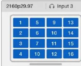
When first powering your Blackmagic MultiView 16 you'll see the 'home' screen displayed on the built in LCD. The home screen is the default display showing a convenient overview of settings, such as:
- Multi view output frame rate – Located in the upper left corner, this displays the selected frame rate for your Ultra HD SDI multi view output.
- Audio input – This information is located next to the multi view output frame rate and displays which SDI input is being used for embedded audio in the HDMI and SDI multi view output signal.
- Multi view layout – This displays your selected multi view layout.
text_image
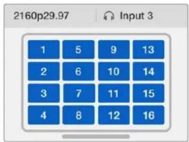
2160p29.97 Input 3 1 5 9 13 2 6 10 14 3 7 11 15 4 10 12 16The 'home' screen is the default display on Blackmagic MultiView 16's control panel LCD. This screen displays your selected multi view layout, the frame rate for the multi view SDI output, and the selected SDI input used to embed audio into the multi view output.
Control Panel Buttons
The illuminated buttons on Blackmagic MultiView 16's control panel make it very easy to adjust settings and set your sources and views.

text_image
1 4 7 10 13 16 SRC 2 5 8 11 14 SOLO VIEW 3 6 9 12 15 SET MENU Blackmagic MultiView 16 BlackmagicdesignBlackmagic MultiView 16's control panel buttons let you easily change settings and switch views from the front of the unit
Solo Button
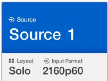
You can monitor a view in full screen by pressing the 'solo' button. Now press any view button on the control panel to monitor that view in full screen mode. Press solo again to return to the multi view layout.
text_image
Source Source 1 Layout Input Format Solo 2160p60The solo feature lets you monitor a view in full screen mode
Menu Button
Press the 'menu' button to open the settings screen. Change a setting using the rotary knob and set button, then press the menu button again to return to the 'home' screen.
Set Button
Press the 'set' button to select a setting to adjust. After changing a setting, press the set button again to confirm the change.
Source and View buttons
These buttons let you select which input source you want to display in a desired view. When navigating settings menus, the source and view buttons can also be used to move up and down through setting options.
Rotary Knob
Use the rotary knob to scroll through settings, or to select menu items on the settings screen. If you're unhappy with a selection, you can return to a previously selected setting by pressing the rotary knob.
Turn the rotary knob clockwise or counter clockwise to select between two options in a menu. Settings can also be turned on or off by pressing the knob.
Setting your Sources and Views on Blackmagic MultiView 16
One of the key features of Blackmagic MultiView 16 is the ability to assign your connected SDI sources to different views. By adjusting these settings you can easily change the arrangement of your views. For example, you may want SDI input 5 to appear on view 1.
To set which source appears on a desired view:
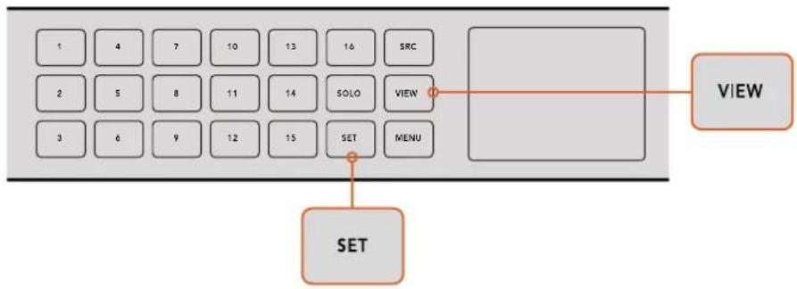
1 Press the 'view' button on the front control panel to open the view selection screen. The view selection will be highlighted with a blue background.
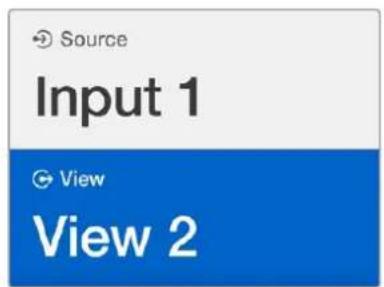
2 Press a numbered view button to select your desired view. Alternatively, you can use the rotary knob to scroll through the views. Confirm your setting by pressing the 'set' button.
3 Press the 'src' button. The source section of the LCD will be highlighted.
4 Press a numbered view button on the control panel to select your desired input. Alternatively, you can use the rotary knob to scroll through your inputs on the LCD.
5 Press the 'set' button to confirm your setting.
flowchart
graph TD
    A["SET"] --> B["VIEW"]
    C["1 4 7 10 13 16 SRC"] --> D["SOLO VIEW"]
    E["2 5 8 11 14"] --> D
    F["3 6 9 12 15"] --> D
    G["SET MENU"] --> D
    H[" "] --> I["VIEW"]
To set a source to a view, press the 'view' button to enter the view setting, make your selection, then press the 'set' button to confirm your setting
Setting your Layout on Blackmagic MultiView 16
On Blackmagic MultiView 16, you can select the number of views that appear on your multi view output. For example, if you have 4 inputs connected, you can easily select the 2x2 layout which displays four views in a vertical x horizontal grid. For optimum monitoring of your inputs, select the view layout to suit the number of inputs connected.
There are four multi view layouts you can choose from:
- 2x2 displays 4 views. If you have an Ultra HD monitor connected, each source will be displayed in native HD resolution.
- 3x3 displays 9 views.
- 4x4 displays all 16 views.
TIP You can also monitor a view in full screen mode by pressing the 'solo' button on Blackmagic MultiView 16's control panel, then selecting a view button. On Blackmagic MultiView 4, press the solo button marked '1' on the Teranex Mini Smart Panel.
text_image
Source Input 1 View View 2Select your view you wish to assign a source to using the rotary knob or view buttons
text_image
Settings Layout 4x4 Audio In Source 1 Overlay Video Out NetworkHighlight the menu item you with to adjust and press "set" to open its settings
text_image
< Overlay Border On Labels On Audio Meters On SDI Tally On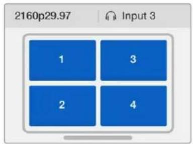
heatmap
| Category | Value | |---|---| | 1 | 2160p29.97 | | 2 | 2160p29.97 | | 3 | 2160p29.97 | | 4 | 2160p29.97 |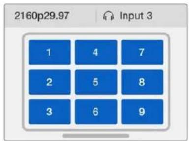
text_image
2160p29.97 Input 3 1 4 7 2 5 8 3 6 9You can choose from 3 different multi view layouts to best suit the number of inputs you have connected
text_image
2160p29.97 Input 3 1 5 9 13 2 6 10 14 3 7 11 15 4 8 12 16Audio In
This setting is used to select the SDI input from which audio will be taken and embedded into the multi view outputs.
Overlay
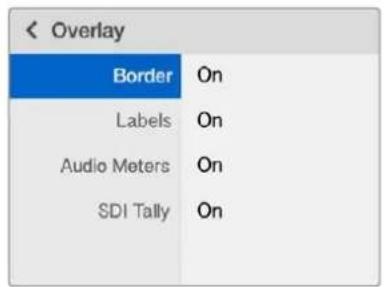
This submenu lets you change the appearance of your multi view by turning overlay features on or off.
Overlay features are:
- Borders – Lets you separate each view in a grid like pattern.
- Labels – Makes 'view' labels visible or hidden. Labels can be changed using Blackmagic MultiView Setup.
- Audio Meters – Turns audio VU meters on or off for all the views. The first 2 channels embedded in each SDI signal are displayed in each view, which means you can monitor audio levels together with the picture.
- SDI Tally – When Blackmagic MultiView 16 has an ATEM switcher's program SDI output connected to input 16, you can view tally borders around a view when its source is switched to air. You can turn this feature on or off using the SDI tally overlay setting.
For tally to work properly, make sure you connect your Blackmagic MultiView 16's inputs so they match the input numbers on your ATEM switcher or tally may be displayed on the wrong view.
Video Out
The 'video out' settings let you control output options on your Blackmagic MultiView 16.
- Video Format – Use this setting to change your Ultra HD multi view output frame rate to 2160p29.97 or 2160p25. The HD multi view output frame rate will conform to the Ultra HD output. Press the rotary knob if you want to cancel the setting change, or return to the previous menu.
- HD Output – Select interlaced or progressive for the HD multi view output. If 2160p29.97 is the selected video format the HD output can be either 1080p29.97 or 1080i59.94. Similarly when 2160p25 is selected the HD output can be either 1080p25 or 1080i50.
Network
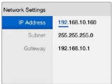
The 'network' settings let you set the IP, Subnet and Gateway addresses for your Blackmagic MultiView 16 when connecting to a network.
To set your Blackmagic MultiView 16's IP address:
1 Press the 'menu' button on the front control panel and use the rotary knob to highlight the 'networking' tab on the LCD menu.
2 Press the 'set' button to enter the network settings screen.
3 Turn the rotary knob to select the "IP address" tab.
4 Press the 'set' button to highlight the first field of the IP address. Use the rotary knob to change values.
5 Press 'set' to confirm the first field, then repeat the above step for the next three fields. If you need to assign the subnet and gateway address, they can be set using the same method.
6 Press the menu button twice to return to the home screen.
text_image
B2P IN 1234567 USB USBConnecting Blackmagic MultiView 16 to an Ethernet network will allow you to control the unit from another location
bar
Network Settings | Category | Value | |---|---| | IP Address | 192.168.10.160 | | Subnet | 255.255.255.0 | | Gateway | 192.168.10.1 |Use the rotary knob or the view buttons on Blackmagic MultiView 16's control panel to assign values to your network settings
Teranex Mini Smart Panel
The Teranex Mini Smart Panel mounts to the front of your Blackmagic MultiView 4 and replaces the original basic panel. You get fast access to your settings using buttons, a rotary knob and built in LCD.
Installing Teranex Mini Smart Panel
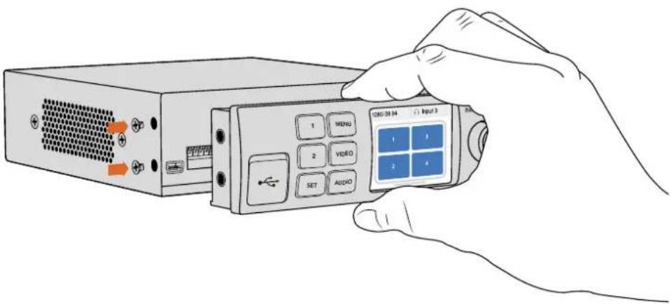
Installing your optional Smart Panel is easy and because the panels are hot swappable you don't even need to turn off your Blackmagic MultiView 4 when installing it.
1 Remove the two M3 screws on each side of your Blackmagic MultiView 4's basic front panel using a Pozidriv 2 screwdriver and gently pull the panel away from the front of the unit.
2 On the inside of the basic panel, you'll notice a small clear plastic tube attached to the bottom corner. This tube directs light from the LED inside the unit to illuminate the status indicator on the basic panel. This tube should stay attached to the basic front panel.
TIP If reattaching the basic front panel, make sure the light pipe for the power indicator is aligned with the slot in the front of the unit.
3 Align the connector on the rear of the Smart Panel with the adjoining connector on the face of your Blackmagic MultiView 4 and gently push the Smart Panel towards the unit until the connectors are firmly seated. The Smart Panel should make a firm connection and fit neatly inside the face of your Blackmagic MultiView 4.
4 Re-insert the M3 screws from the original panel.
If your Blackmagic MultiView 4 is installed in a Teranex Mini Rack Shelf, you will need to remove the unit from the rack shelf to access the front panel screws.
See the 'Rack Installation' section for more information.
Your Blackmagic MultiView 4's USB port is still accessible with the Smart Panel attached. To access the port, simply open the rubber USB dust cover. With the Smart Panel installed, the front panel small switches are covered up and no longer used. This is because all settings can now be changed via the LCD menus.
natural_image
Illustration of a hand holding a remote control device with labeled buttons (MENU, VIDEO, SET, AUDIO) and ports (no text or symbols on the device itself)When installing the Teranex Mini Smart Panel to your Blackmagic MultiView 4, holding the panel with your fingers and thumb aligned with the panel's rear connector will help guide it into place.
TIP The original basic panel is very strong, so if you need to mount your Blackmagic MultiView 4 in the back of a rack system or in areas where there are lots of cables or activity, you can always reinstall the original basic panel.
Teranex Mini Smart Panel Features
The features of the Smart Panel are similar to the MultiView 16's built in control panel. The home screen is the first feature you'll see on the LCD and is the default display showing a convenient overview of settings, such as:
- Multi view output frame rate – Located in the upper left corner, this displays the selected frame rate for your Ultra HD SDI multi view output.
- Audio input – This information is located next to the multi view output frame rate and displays which SDI input is being used for embedded audio in the HDMI and SDI multi view output signal.
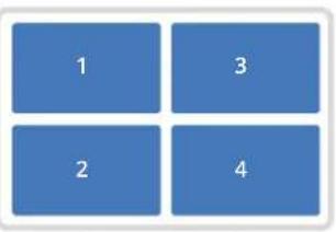
- Multi view layout – This displays the 2x2 multi view layout.
2160p 29.97 Input 3
text_image
1 3 2 4The 'home' screen is the default display on Teranex Mini Smart Panel's LCD
Control Buttons and Rotary Knob
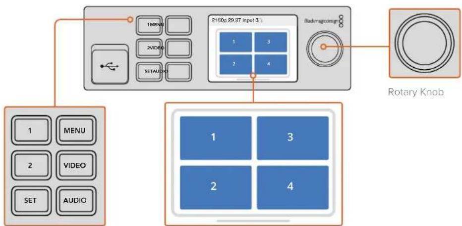
Your Teranex Mini Smart Panel has a set of buttons and a rotary knob that are used to navigate your Blackmagic MultiView 4's settings menu.
- 1 and 2 buttons – Press these buttons to increase or decrease numeric setting values, or to move up or down through menu settings.
- Set – After changing a setting using the 1 and 2 buttons, press the 'set' button to confirm your setting.
- Menu – Press to enter the settings menu for your Blackmagic MultiView 4. You can also press the menu button to step back through menu items all the way to the home screen.
- Video and Audio Buttons – These buttons are specific to Teranex Mini converters and are not used with Blackmagic MultiView 4.
- Rotary Knob – Turn the rotary knob clockwise or counter clockwise to navigate through the menu settings and adjust numeric setting values.
flowchart
graph TD
    A["2160p 29.97 Input 3."] --> B["1MENU"]
    A --> C["2VIDEO"]
    A --> D["SETAUDIO"]
    A --> E["1"]
    A --> F["2"]
    A --> G["3"]
    A --> H["4"]
    A --> I["1"]
    A --> J["2"]
    A --> K["3"]
    A --> L["4"]
    M["Rotary Knob"] --> N["1"]
    M --> O["2"]
    M --> P["3"]
    M --> Q["4"]
Control Buttons
Video monitor – displays the home screen and is used when changing settings
Changing Settings using Teranex Mini Smart Panel
Changing settings using the Teranex Mini Smart Panel is more convenient and you can immediately confirm your settings visually on the LCD.
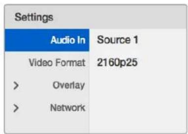
To enter your Blackmagic MultiView 4's setup menu, press the 'menu' soft button on the Teranex Mini Smart Panel. Here you can access the following settings.
text_image
Settings Audio In Source 1 Video Format 2160p25 > Overlay > NetworkHighlight the menu item you wish to adjust and press "set" to select it. Scroll through the settings using the rotary knob
Audio In
This setting is used to select the SDI input from which audio will be taken and embedded into the multi view outputs.
Video Format
Your Blackmagic MultiView 4 can be set to Ultra HD or HD output at either 29.97 or 25 frames per second. Use this setting to cycle through the available resolution and frame rate options.
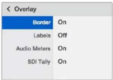
Overlay
The overlay submenu lets you set the appearance of overlay features on or off.
Overlay features are:
- Borders – Lets you separate each view in a grid like pattern.
- Labels – Makes 'view' labels visible or hidden. Labels can be changed using Blackmagic MultiView Setup.
- Audio Meters – Turns audio VU meters on or off for all the views. The first 2 channels embedded in each SDI signal are displayed in each view, which means you can monitor audio levels together with the picture.
text_image
< Overlay Border On Labels Off Audio Meters On SDI Tally OnNetwork
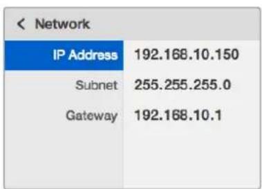
The 'network' settings let you set the IP, Subnet and Gateway addresses for your Blackmagic MultiView 4 when connecting to a network.
To set your Blackmagic MultiView 4's IP address:
1 Press the 'menu' button on the front control panel and use the rotary knob to highlight the 'networking' tab on the LCD menu.
2 Press the 'set' button to enter the network settings screen.
3 Turn the rotary knob to select the "IP address" tab.
4 Press the 'set' button to highlight the first field of the IP address. Use the rotary knob to change values.
5 Press 'set' to confirm the first field, then repeat the above step for the next three fields. If you need to assign the subnet and gateway address, they can be set using the same method.
6 Press the menu button twice to return to the home screen.
text_image
< Network IP Address 192.168.10.150 Subnet 255.255.255.0 Gateway 192.168.10.1Use the rotary knob or the "1" and "2" buttons on Teranex Mini Smart Panel to assign values to your Blackmagic MultiView 4 network settings
Changing Settings using Switches
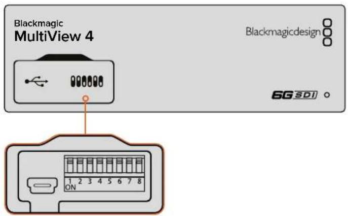
On Blackmagic MultiView 4 and MultiView 4 HD, there are small built in switches to let you change settings. On the Blackmagic MultiView 4, the switches are on the front panel, behind a rubber dust cap.
On Blackmagic MultiView 4 HD, the switches are on the side of the unit.
text_image
Blackmagic MultiView 4 Blackmagicdesign 6G SDI 1 2 3 4 5 6 7 8 ONChange settings by adjusting the switches with a pen

natural_image
Diagram of a rectangular electronic device with two ports and a central connector pinout (no text or symbols)On Blackmagic MultiView 4 HD, the small switches are located on the rear side panel
Built in Switches
You'll find a switch settings diagram printed on the base of the unit. Ensure your switch settings correspond to the legend by observing the switch numbers from 8 to 1, left to right.
TIP Even though switch settings are printed on the base of the unit, new features in later updates can add new settings so it's worth checking the latest version of this manual for the most up to date information. You can download the latest version from the Blackmagic Design support center at www.blackmagicdesign.com/support
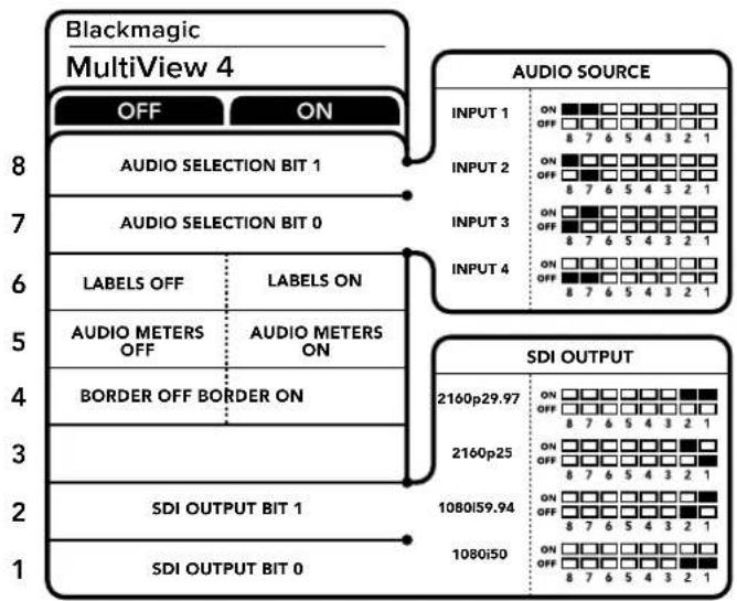
Switch Settings for Blackmagic MultiView 4
text_image
Blackmagic MultiView 4 OFF ON AUDIO SOURCE INPUT 1 ON OFF 8 7 6 5 4 3 2 1 INPUT 2 ON OFF 8 7 6 5 4 3 2 1 INPUT 3 ON OFF 8 7 6 5 4 3 2 1 INPUT 4 ON OFF 8 7 6 5 4 3 2 1 AUDIO SELECTION BIT 1 AUDIO SELECTION BIT 0 LABELS OFF LABELS ON AUDIO METERS OFF AUDIO METERS ON BORDER OFF BORDER ON SDI OUTPUT BIT 1 SDI OUTPUT BIT 0 2160p29.97 ON OFF 8 7 6 5 4 3 2 1 2160p25 ON OFF 8 7 6 5 4 3 2 1 1080i59.94 ON OFF 8 7 6 5 4 3 2 1 1080i50 ON OFF 8 7 6 5 4 3 2 1Switch settings or Blackmagic MultiView 4
Blackmagic MultiView 4's switches let you change the following settings:
Switch 8 and 7 – Audio Selection
Switches 8 and 7 are represented as bits 1 and 0 respectively. This means that by setting various on/off combinations of switches 8 and 7 you can select which SDI input is being used for embedded audio in the HDMI and SDI multi view output signal.
Audio Selection Table
| Audio Source Switch 8 Switch 7 Switch Diagram | ||
| Input 1 ON ON | 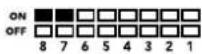 | |
| Input 2 ON OFF | 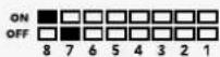 | |
| Input 3 OFF ON | 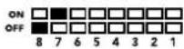 | |
| Input 4 OFF OFF | 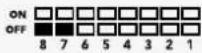 | |
Switch 6 – Labels
Set switch 6 to 'on' to display labels for each window in your multi view output signal. These labels can be set using Blackmagic MultiView setup as detailed later in this manual. Set switch 6 to 'off' to hide labels.
Switch 5 – Audio Meters
Set switch 5 to 'on' to display audio meters for each window in your multi view output signal. Set switch 5 to 'off' to hide audio meters.
Switch 4 – Borders
Set switch 4 to 'on' to display borders between each MultiView window. Set switch 4 to 'off' to hide borders.
Switch 2 and 1
Switches 2 and 1 are represented as bits 1 and 0 respectively. This means that by setting various on/off combinations of switches 2 and 1 you can select the output format of your MultiView 4's SDI signal.
SDI Output Selection Table
| SDI Output Switch 2 Switch 1 Switch Diagram | ||
| 2160p29.97 ON ON | 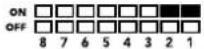 | |
| 2160p25 ON OFF | 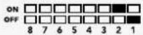 | |
| 1080i59.94 OFF ON | 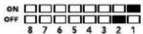 | |
| 1080i50 OFF OFF | 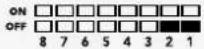 | |
NOTE When using the optional Teranex Mini Smart Panel, the switch settings will be overridden by the Smart Panel settings. Your Blackmagic MultiView 4 will retain its last settings whether applied via switch, Smart Panel or Blackmagic MultiView Setup software. If reverting to switch control after removing the Smart Panel or updating your Blackmagic MultiView 4's settings via software, you may need to toggle individual switches for new settings to take effect.
Switch Settings for Blackmagic MultiView 4 HD
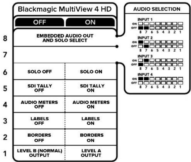
flowchart
graph TD
    A["Blackmagic MultiView 4 HD"] --> B["ABBEDDED AUDIO OUT AND SOLO SELECT"]
    B --> C["SOLO OFF"]
    B --> D["SOLO ON"]
    C --> E["SDI TALLY OFF"]
    C --> F["SDI TALLY ON"]
    E --> G["AUDIO METERS OFF"]
    E --> H["AUDIO METERS ON"]
    F --> I["LABELS OFF"]
    F --> J["LABELS ON"]
    G --> K["BORDERS OFF"]
    G --> L["BORDERS ON"]
    H --> M["LEVEL A OUTPUT"]
    I --> N["LEVEL B (NORMAL) OUTPUT"]
    style A fill:#f9f,stroke:#333
    style B fill:#ccf,stroke:#333
    style C fill:#cfc,stroke:#333
    style D fill:#fcc,stroke:#333
    style E fill:#ffc,stroke:#333
    style F fill:#ffc,stroke:#333
    style G fill:#cfc,stroke:#333
    style H fill:#cfc,stroke:#333
    style I fill:#cfc,stroke:#333
    style J fill:#cfc,stroke:#333
    style K fill:#cfc,stroke:#333
    style L fill:#cfc,stroke:#333
The switch legend on the base of the Blackmagic MultiView 4 HD gives you all the information you need to change settings.
Blackmagic MultiView 4 HD's switches let you change the following settings:
Switch 8 and 7 - SDI Audio Embed and Solo Select
Switches 8 and 7 are grouped together to provide 4 ON/OFF combinations. Having four different combinations allows the audio from any one of the four SDI inputs to be embedded into the multi view output. In solo mode, audio follows video, so you can use these switches to select the view source and audio source.
Audio Selection Table
| Audio Source Switch 8 Switch 7 Switch Diagram | ||
| Input 1 OFF OFF | 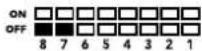 | |
| Input 2 ON OFF |  | |
| Input 3 OFF ON |  | |
| Input 4 ON ON | 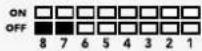 | |
Switch 6 – Solo View
Set switch 6 to ON to display solo view. This lets you monitor a single view full screen. Set switch 6 to OFF to monitor the 2x2 multi view layout.
The audio embedded in the solo view output matches your view source selection automatically. Use switch 7 and 8 to select a combined audio and view source for the solo layout. In 2x2 multi view layout, switch 7 and 8 select the audio input.
Switch 5 – Tally
Set switch 5 to ON to display tally borders on the views. Set to OFF to hide tally borders.
All additional data including ATEM SDI camera control, time code and closed captions pass through unaltered when in solo mode.
TIP The input number for each view can be set using Blackmagic MultiView Setup software. Make sure the view number matches the input number set on your switcher so tally displays correctly. Refer to the 'Tally Configuration' section for more information.
Switch 4 – Audio Meters
Set switch 4 to ON to display audio meters on the views. Set to OFF to hide audio meters.
Switch 3 – View Labels
Set switch 3 to ON to display labels on each view. Set to OFF to turn labels off.
Switch 2 – Borders
Set switch 2 to ON to display the view borders, and to OFF to turn borders off.
Switch 1 – Level A and Level B 3G-SDI
Set switch 1 to OFF to select level B 3G-SDI output, or to ON to select level A 3G-SDI. This lets you change the 3G-SDI output level for compatibility with other SDI equipment.
Using Blackmagic MultiView Setup
Blackmagic MultiView Setup lets you easily configure your Blackmagic MultiView from any Mac or Windows PC, as well as update the unit's internal software. The utility is intuitive and easy to use, plus if you have Blackmagic MultiView 4 connected to a network, you can even change settings via Ethernet so you don't have to plug in via USB.
Installing Blackmagic MultiView Setup
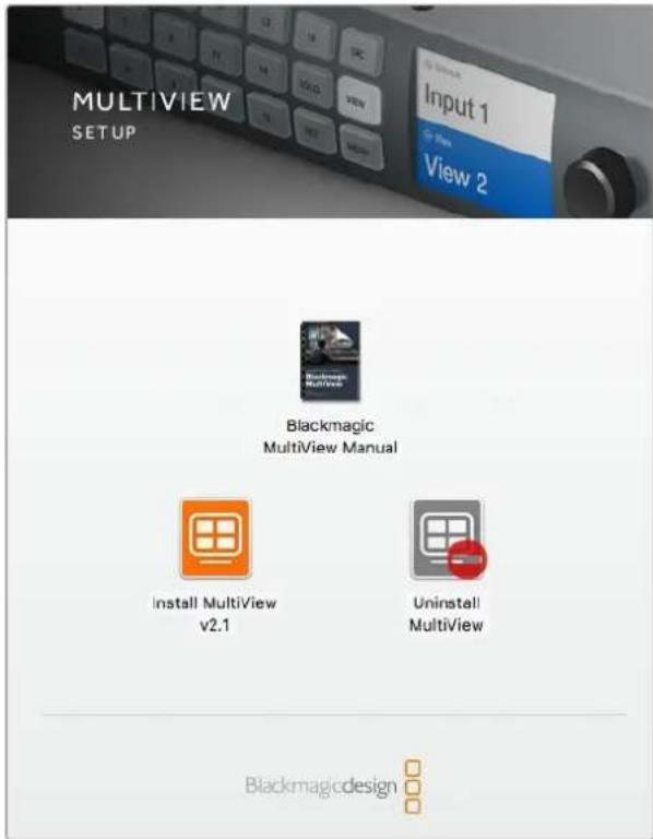
Blackmagic MultiView Setup runs on 64-bit versions of Windows and on the latest Sierra and High Sierra versions of macOS.
text_image
MULTIVIEW SETUP Input 1 View 2 Blackmagic MultiView Manual Install MultiView v2.1 Uninstall MultiView BlackmagicdesignTo install the Blackmagic MultiView setup, double click the installer and follow the prompts
Windows installation
1 Double click the installer file from the supplied media or from your downloads folder if you downloaded the software from the Blackmagic Design website.
2 Follow the install prompts and accept the terms in the license agreement and Windows will automatically install the software.
Click the Windows 'start' button and then All Programs>Blackmagic Design>MultiView. The multi view folder contains the Blackmagic MultiView setup application.
Mac OS X installation
1 Double click the installer file from the supplied media or from your downloads folder if you downloaded the software from the Blackmagic Design website.
2 Follow the install prompts and Mac OS X will automatically install the software.
A folder called "Blackmagic MultiView" will be created within your applications folder, containing the Blackmagic MultiView Setup application.
Blackmagic MultiView Setup Home Page
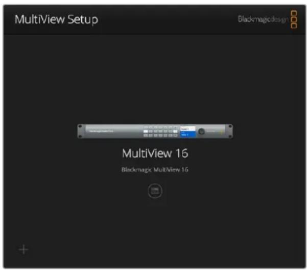
The first thing you will see after launching Blackmagic MultiView Setup is the software home page. If you have multiple Blackmagic MultiView connected to your network, you can select them by clicking on the arrows on the left and right side of the home page.
To access settings for your Blackmagic MultiView, click on the circular settings icon underneath the product image, or you can click on the image itself.
text_image
MultiView Setup Blackmagic design MultiView 16 Blackmagic MultView 16Blackmagic MultiView Setup lets you change your Blackmagic MultiView settings from a computer when connected via Ethernet or USB
Changing Settings using Blackmagic MultiView Setup
Click on the settings icon to open the setup settings for your Blackmagic MultiView. In the settings window you will see three tabs named 'sources', 'views' and 'configure'. On Blackmagic MultiView 4 and MultiView 4 HD, the 'views' setting is not required as views are not adjustable via the Videohub Control software. Blackmagic MultiView 4 HD also has a 'tally' menu for changing tally settings.
TIP Make sure your network settings on the unit matches that on your computer for sources to be displayed.
text_image
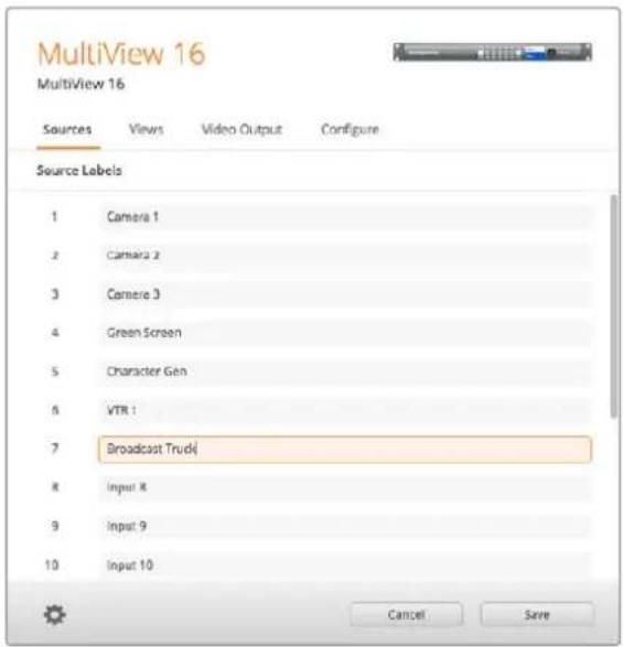
MultiView 16 MultiView 16 Sources Views Video Output Configure Source Labels 1 Camera 1 2 Camera 2 3 Camera 3 4 Green Screen 5 Character Gen 6 VTR 1 7 Broadcast Truck) 8 Input: R 9 Input: 9 10 Input: 10 Cancel SaveUse Blackmagic MultiView Setup to customize input labels so you can quickly identify each source within the multi view layout
- Sources – Lets you customize your input labels. This changes how your sources are labelled on your multi view display.
- Views – This tab is only relevant when controlling Blackmagic MultiView 16 via Videohub Control software. By changing the name of the views, you can make them easier to identify within the destinations panel in the Videohub Control software.
- Video Output – Lets you customize the video format and SD output aspect ratio from Blackmagic MultiView 4 HD.
- Configure – The 'configure' tab gives you control over settings such as device name customization, video output and overlay settings, plus network settings and serial control adjustments.
Sources
Customizing Input Labels
Labeling your sources lets you quickly identify each source within the multi view layout. You can also save and load label sets, so if you regularly use your Blackmagic MultiView for different applications, you can quickly load labels without the need to re-enter them.
Labels are visible in the Videohub Control software and also to networked Videohub control panels.
To customize your input labels:
1 Click on the 'sources' tab.
2 Click the text box for the input source name you want to change and enter a new label name.
3 Click 'save' to confirm your setting.
Views
Customizing View Labels
On Blackmagic MultiView 16, you can change the labels of the views so they are easier to identify as destinations when controlling your MultiView 16 via Videohub Control software.
To customize the view labels:
1 Click on the 'views' tab.
2 In the 'output labels' setting, click the text box for the view you want to change and enter a new label name.
3 Click 'save' to confirm your setting.
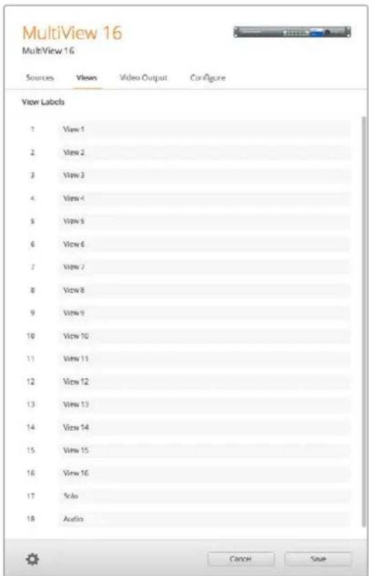
When the 'view' labels are at their default state, you will notice output 17 is labelled 'solo' and output 18 is labelled 'audio'.
Output 17 lets you change the software label for the 'solo' setting which is controlled using your Blackmagic MultiView 16's front panel. This is beneficial when controlling your MultiView 16 using Blackmagic Videohub Control software. Customizing the 'solo' output label in Blackmagic MultiView Setup lets you change how it appears in Blackmagic Videohub Control.
Output 18 relates to the 'audio in' setting in your Blackmagic MultiView 16's LCD menu, which routes the audio you wish to embed in your multi view output. Similar to the 'solo' output label, you can change the view label so you can customize its appearance when controlling Blackmagic MultiView 16 using Blackmagic Videohub Control.
text_image
MultiView 16 MultiView 16 Sources Views Video Output Configure View Labels 1 View 1 2 View 2 3 View 3 4 View 4 5 View 5 6 View 6 7 View 7 8 View 8 9 View 9 10 View 10 11 View 11 12 View 12 13 View 13 14 View 14 15 View 15 16 View 16 17 Solo 18 Audio Cancel SaveThe inclusion of the "solo" and "audio" output labels let you change their names so you can customize how they appear when controlling your Blackmagic MultiView 16 using Blackmagic Videohub Control
Video Output
Video Format and HD Output
Video format settings differ slightly between Blackmagic MultiView models.
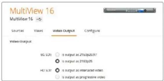
Blackmagic MultiView 16 can output HD and Ultra HD video simultaneously. You can also choose the video frame rate you want to output. For example if you want to output a signal that conforms to the format commonly used in the USA, select 2160p29.97 and the HD output will automatically match the frame rate.
In this example, if 2160p29.97 is selected as the video format, you can set the HD output to 1080p29.97 or 1080i59.94 to suit your video requirements.
text_image
MultiView 16 MultiView 16 → Sources Views Video Output Configure Video Output 6G SDR: Is output as 2160p25/97 Is output as 2160p25 HDI SDR: Is output as interlaced video Is output as progressive videoThe radio buttons in the 'video output' tab for MultiView 16 are used to set the view layout, Ultra HD video format, HD output and SD aspect ratio
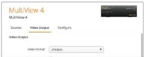
On Blackmagic MultiView 4 you can choose whether to output Ultra HD or HD video via the SDI output, as well as set the frame rate. These settings are available in the 'video format' dropdown menu.
text_image
MultiView 4 MultiView 4 Sources Video Output Configure Video Output Video Format: J160p25The 'video output' tab for Blackmagic MultiView 4 contains a dropdown list of video format options that covers both resolution and frame rate
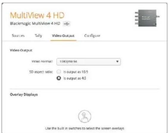
On Blackmagic MultiView 4 HD, you can use the 'video format' menu to select the HD frame rate and whether to output video as interlaced or progressive scan. You can also set the SD aspect ratio for your Blackmagic MultiView 4 HD to 16:9 or 4:3.
text_image
MultiView 4 HD Blackmagic MultiView 4 HD -6- Sources Toily Video Output Configure Video Output Video Format: 1080p58.94 5D aspect ratio: Is output as 15:9 Is output as 4:3 Overlay Displays Use the built in switches to select the screen overlaysThe 'video output' tab for Blackmagic MultiView 4 HD lets you set the output HD resolution and frame rate, plus set it to interlaced or progressive scan
Changing the Multi View Layout
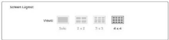
Similar to the 'layout' settings on Blackmagic MultiView 16's control panel LCD menu, you can also change the layout using the setup software. Choose the layout setting you wish to use by clicking on the desired layout icon in the 'details' settings.
text_image
Screen Layout: Views: Solo 2 x 2 3 x 3 4 x 4Set the screen layout for MultiView 16 in the 'video output' tab.
Tally Configuration
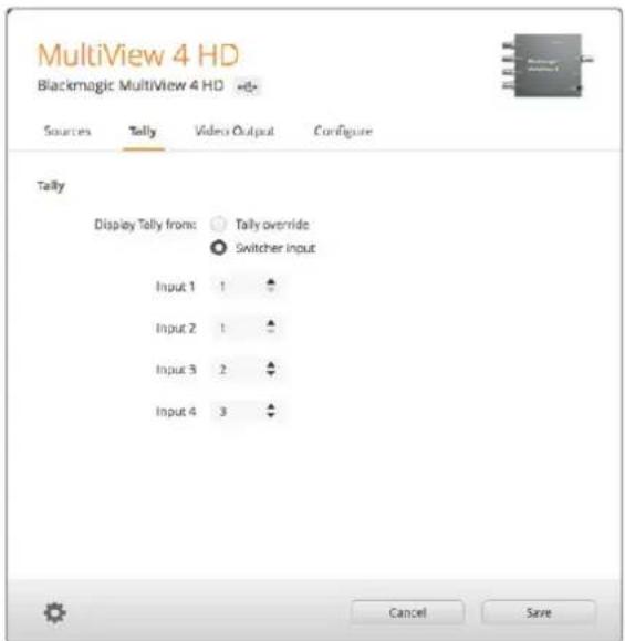
On Blackmagic MultiView 4 HD, you can set the tally configuration to tally override, or flag as sent by a Blackmagic camera, or by camera number when sent from the ATEM switcher to input 4 of the MultiView 4 HD.
text_image
MultiView 4 HD Blackmagic MultiView 4 HD Sources Tally Videos Output Configure Tally Display Tally from: ○ Tally override ● Switcher input Input 1 1 Input 2 1 Input 3 2 Input 4 3 Cancel SaveTally options on the 'Tally' menu of the MultiView setup utility.
When selecting tally to correspond to the switcher input you can enter the camera number from 1 to 99 into the text field for inputs 1 to 4.
Tally Override
Tally signals are generally provided by the program return feed connected to the last SDI input on your MultiView. However, there may be times when you want to have all your cameras connected to all the views.
If you are using Blackmagic Design cameras connected to an ATEM switcher, or to another SDI switcher with a third party tally system, you can enable tally override. With tally override selected, your MultiView 4 HD will now look for tally signals embedded in each SDI input signal. This means all views receive their tally signal independently, rather than a collective tally signal via the program return on the unit's last input.
TIP ‘Tally override’ mode works with Blackmagic URSA Mini, URSA Mini 4K, URSA Mini Pro, and URSA Broadcast cameras that are connected to a Blackmagic ATEM switcher or Blackmagic Camera Fiber Converter. For information on how to connect a third party switcher or third party tally, refer to the Blackmagic 3G-SDI Shield for Arduino manual.
SD Aspect Ratio
If 4:3 SD video is connected to your Blackmagic MultiView, check the 'set to 4:3' checkbox. This ensures your 4:3 video displays using the correct aspect ratio.
If 16:9 SD video is connected, check the 'set to 16:9' checkbox to display the image correctly in its view.
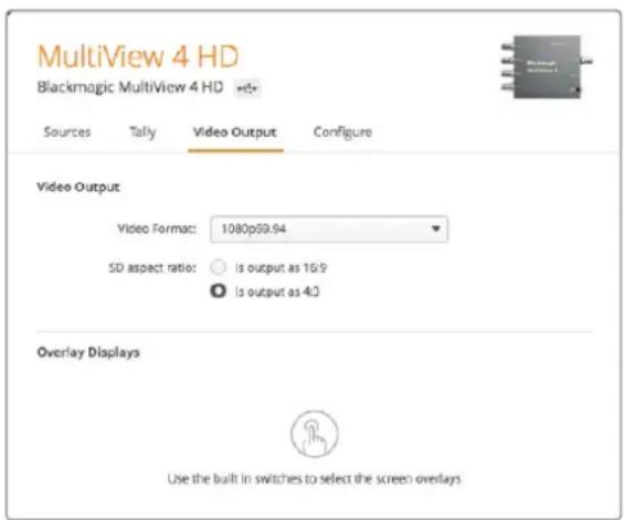
When you input an SD source to Blackmagic MultiView 4 HD, you can switch between a 16:9 and 4:3 output using the setup utility. On the 'Video Output' menu, select an option for the SD aspect ratio.
text_image
MultiView 4 HD Blackmagic MultiView 4 HD Sources Tally Video Output Configure Video Output Video Format: 1080p59.94 SD aspect ratio: Is output as 16:9 Is output as 4:3 Overlay Displays Use the built in switches to select the screen overlaysSD aspect ratio options on the 'Video Output' menu of the MultiView setup utility.
Overlay Display
Blackmagic MultiView 16 and Blackmagic MultiView 4 have checkboxes in the 'overlay' settings to enable each feature on your Blackmagic MultiView.
Overlay features are:
- Borders: Lets you separate each view in a grid like pattern.
- Labels: Makes 'view' labels visible or hidden. Labels can be changed using Blackmagic MultiView Setup.
- Audio Meters: Turns audio VU meters on or off for all the views. The first 2 channels embedded in each SDI signal are displayed in each view, which means you can monitor audio levels together with the picture.
- SDI Tally: When your Blackmagic MultiView has an ATEM switcher's program SDI output connected to input 16 on Blackmagic MultiView 16, or input 4 on Blackmagic MultiView 4 models, you can view tally borders around a view when its source is switched to air. The tally feature can be enabled by selecting the 'turn on SDI tally' checkbox in the overlay settings. Deselect to disable the feature. An input number can be assigned in the setup software utility so tally displays correctly.
Overlay Displays
√ Turn on borders
√ Turn on labels
√ Turn on audio meters
√ Turn on SDI tally
On Blackmagic MultiView 16 and Blackmagic MultiView 4, the overlay settings in the 'configure' tab lets you turn overlay features on or off such as borders, view labels, audio meters, or even SDI tally borders
TIP For tally to work properly, make sure you connect all your Blackmagic MultiView inputs so they match the input numbers on your ATEM switcher or tally may be displayed on the wrong view.
Configure
Naming your Blackmagic MultiView
The 'Configure' tab differs between Blackmagic MultiView models.
The 'Configure' tab for a Blackmagic MultiView 16 or Blackmagic MultiView 4 has groups of settings for 'Details', 'Overlay', and 'Network settings'. For Blackmagic MultiView 4 HD, it shows the label and software version number and has no settings.
To name your Blackmagic MultiView 16 or Blackmagic MultiView 4 so it's easy to identify when used remotely:
1 Click on the 'configure' tab.
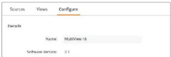
2 In the 'details' setting, click the 'name' text box and enter a new label for your Blackmagic MultiView.
3 Click 'save'.
text_image
Sources Views Configure Details Name: MultiView 16 Software Version: 2.1Use Blackmagic MultiView Setup to name your Blackmagic MultiView 16 so it's easy for network users to identify
Network and Serial Control Settings
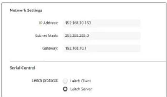
Network and serial control settings can be set using Blackmagic MultiView Setup when your Blackmagic MultiView 16 is connected to your computer via USB. You can also change these settings using the front control panel LCD menu. When configuring Blackmagic MultiView 4, only network settings are available.
To change network settings, simply click in the text box and enter the values with your keyboard, or check the desired checkbox.
text_image
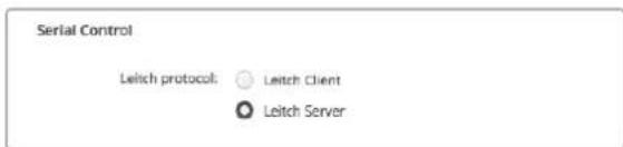
Network Settings IP Address: 192.168.10.160 Subnet Mask: 255.255.255.0 Gateway: 192.168.10.1 Serial Control Leitch protocol: Leitch Client Leitch ServerWhen connecting to a network, you may need to change your MultiView 16's 'network settings' to suit. 'Serial control' settings lets you set your MultiView 16 for Lietch client or server configuration based on your RS-422 remote control setup requirements
To set up serial control, connect Blackmagic MultiView 16 to your computer via USB and follow the steps below:
1 Launch Blackmagic MultiView setup and select your Blackmagic MultiView 16 by clicking on the product image or the settings icon below it.
2 Click on the 'configure' tab and set the "Leitch Protocol" switch to "Leitch Client" if your Blackmagic MultiView 16 is to act as a client of a connected control panel, or "Leitch Server" if your unit is to be controlled from an automation system or third party router control system.
3 Click on the 'save' tab to confirm your setting.
text_image
Serial Control Leitch protocol: ○ Leitch Client ● Leitch ServerSelect either 'client' or 'server' when using RS-422 serial control
Saving and Loading Label Sets
If you are regularly using a set of labels for a recurring project, you can easily save them to a file and load them later.
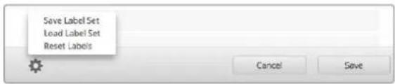
To save your labels, click on the gear icon in Blackmagic MultiView setup to open the 'label set' settings and select "save label set". Choose a location to store the file and click 'save'.
To load your labels, click on the gear icon to open the 'label set' settings and select "load label set". Navigate to your saved label set file and click 'load'.
text_image
Save Label Set Load Label Set Reset Labels Cancel SaveUse Blackmagic MultiView setup to save and load labels
Updating the Internal Software
Occasionally, the internal software in your Blackmagic MultiView will need to be updated. Updates to internal software can provide new features, compatibility with new hardware, and support for new formats.
To update your Blackmagic MultiView internal software:
1 Connect your Blackmagic MultiView to your computer via USB or Ethernet.
2 Launch Blackmagic MultiView setup and it will automatically display any Blackmagic MultiViews that are connected to your network.
3 Select your Blackmagic MultiView by clicking on the product image or the settings icon below the product name.
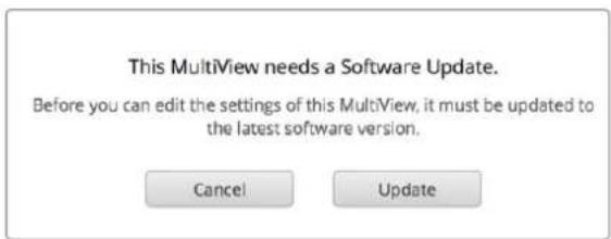
4 Blackmagic MultiView setup will inform you if an update is required.
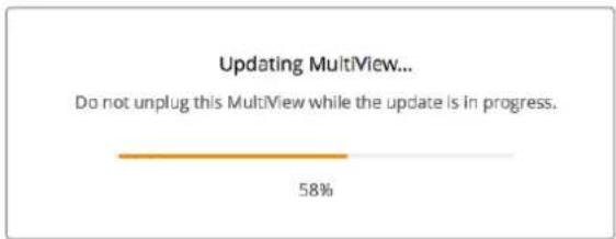
5 If an update is required, click the 'update' button and allow the software to install. Make sure your Blackmagic MultiView is not unplugged while the update is in progress.
6 Click the 'close' button when the update is finished.
text_image
This MultiView needs a Software Update. Before you can edit the settings of this MultiView, it must be updated to the latest software version. Cancel UpdateClick the 'update' button to install new internal software
text_image
Updating MultiView... Do not unplug this MultiView while the update is in progress. 58%Make sure your Blackmagic MultiView is not unplugged while the update is in progress
Using Videohub Control Software
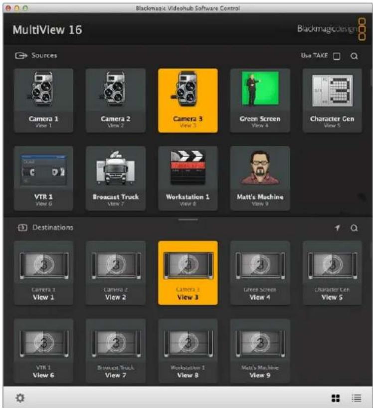
When you have Blackmagic MultiView 16 connected to a network, you can use Blackmagic Videohub Control on a Mac or Windows computer to route Blackmagic MultiView 16's video inputs to different views within your multi view layout. Your Blackmagic MultiView's SDI inputs appear as pushbuttons within the 'sources' panel, while the views appear as pushbuttons within the 'destinations' panel. The Videohub Control application is part of the Videohub software installer which can be downloaded from the Blackmagic Design support center at www.blackmagicdesign.com/support.
NOTE You can use Videohub Control software to route sources to views on Blackmagic MultiView 16, plus other settings such as selecting the view for solo mode, or the audio source for the multi view output. On Blackmagic MultiView 4, you can use Videohub Control software to change the solo source and audio source for the multi view output.
Select your MultiView 16
After launching the Videohub Control software, click on the gear icon to open the 'settings' pop up menu, and choose "select Videohub". Select your Blackmagic MultiView 16's name from the list of connected devices.
If your inputs are labelled, the names you assigned will appear within the Videohub Control software. If they are not labelled they will display as Input 1, Input 2, Input 3, etc.
text_image
Blackmagic Videohub Software Control MultiView 16 Sources Camera 1 View 1 Camera 2 View 2 Camera 3 View 3 Green Screen View 4 Character Gen View 5 VTR 1 View 6 Broadcast Truck View 7 Workstation 1 View 8 Matt's Machine View 9 Destinations Camera 1 View 1 Camera 2 View 2 Camera 3 View 3 Green Screen View 4 Character Gen View 5 VTR 1 View 6 Broadcast Truck View 7 Workstation 1 View 8 Matt's Machine View 9You can use Blackmagic Videohub Control to route Blackmagic MultiView 16's sources to different views
Viewing your Inputs
To see which of your Blackmagic MultiView 16's video inputs is routed to a particular view, click a view pushbutton in the destinations panel. The destination, or view, button will illuminate. In the 'sources' panel, the pushbutton of the routed video input will also illuminate, making it clear which input, or source, is routed to the view.
Routing Inputs to Views
To route a video input to a view, click a view pushbutton from the destination panel, then click an input pushbutton in the sources panel to immediately route that input to the view.
Solo Input
Use the "solo input" pushbutton to determine which input is displayed full screen when the "solo" button is enabled on the Blackmagic MultiView 16's front panel. Simply click on the "solo input" pushbutton in the Videohub Control destinations panel, then click an input pushbutton in the sources panel.
Audio Input
On Blackmagic MultiView 16 and Blackmagic MultiView 4 you can use the “audio input” pushbutton in Videohub Control software to determine which SDI input’s audio is routed to the multi view output. Simply click on the “audio input” pushbutton in the Videohub Control destinations panel, then click an input pushbutton in the sources panel to immediately route that input’s audio to the multi view output.

text_image
Camera 2 Solo Input VTR 1 Audio InputThe "solo input" and "audio input" pushbuttons allow you to change these settings using Videohub Control
Developer Information
Blackmagic Videohub Ethernet Protocol v2.3
Summary
Your Blackmagic MultiView is compatible with the Blackmagic Videohub Ethernet Protocol. It is text based and is accessed by connecting to your Blackmagic MultiView's IP address and TCP port 9990.
NOTE Controlling your MultiView via Ethernet is available on Blackmagic MultiView 16 and Blackmagic MultiView 4, however, most features are relevant to Blackmagic MultiView 16. On Blackmagic MultiView 4, you can change the solo source and audio source for the multi view output.
The multi view sends information in blocks which each have an identifying header in all caps, followed by a full colon. A block spans multiple lines and is terminated by a blank line. Each line in the protocol is terminated by a newline character.
Lines sent to the Blackmagic MultiView 16 can be terminated with line feed, carriage return or both.
Upon connection, the multi view sends a complete dump of the state of the device. After the initial status dump, status updates are sent every time the multi view status changes.
To be resilient to future protocol changes, clients should ignore blocks they do not recognize, up to the trailing blank line. Within existing blocks, clients should ignore lines they do not recognize.
Protocol Preamble
The first block sent by the multi view is always the protocol preamble:
PROTOCOL PREAMBLE:
Version: 2.3
←
The version field indicates the protocol version. When the protocol is changed in a compatible way, the minor version number will be updated. If incompatible changes are made, the major version number will be updated.
Device Information
The next block contains general information about the connected Blackmagic MultiView 16 device. If a device is connected, the multi view will report the attributes of the Blackmagic MultiView 16:
MULTIVIEW DEVICE:
Device present: true
Model name: Blackmagic MultiView 16
Video inputs: 16
Friendly name:
Unique ID:
Video processing units: 0
Video outputs: 16
Video monitoring outputs: 0
Serial P or ts:
This example is for the Blackmagic MultiView 16 which has 16 sources and 18 views including solo which is view 16 and audio which is view 17, referred to here as outputs.
Legend
← line feed
... and so on
Version 2.3 of the Blackmagic Videohub Ethernet Protocol was released with Videohub 4.9.1 software
Initial Status Dump
The next two blocks enumerate the labels assigned to the input and output ports.
INPUT LABELS
0 VTR 1
1 VTR 2
...
OUTPUT LABELS
0 Output feed 1
1 Output feed 2
...
Note: Input and Output labels are always numbered starting at zero in the protocol which matches port one on the chassis.
The next three blocks describe the routing of the view ports.
VIDEO OUTPUT ROUTING←
0 5←
1 3←
...
←
The next block describes the locking status of the views. Each port has a lock status of "O" for ports that are owned by the current client (i.e., locked from the same IP address), "L" for ports that are locked from a different client, or "U" for unlocked.
VIDEO OUTPUT LOCKS:←
0 U←
1 U←
...
←
The last block is the configuration block.
Layout: SOLO or 2x2 or 3x3 or 4x4
Output format: 50i or 50p or 60i or 60p
Solo enabled: True or False
Widescreen SD enable: True or False
Display border: True or False
Display labels: True or False
Display audio meters: True or False
Display SDI tally: True or False
Status Updates
When any route, label, or lock is changed on the multi view by any client, the multi view resends the applicable status block, containing only the items that have changed.
If multiple items are changed, multiple items may be present in the update:
OUTPUT LABELS
7 New output 8 label
10 New output 11 label
Requesting Changes
To update a label, lock or route, the client should send a block of the same form the multi view sends when its status changes. For example, to change the route of output port 8 to input port 3, the client should send the following block:
VIDEO OUTPUT ROUTING
7 2
The block must be terminated by a blank line. On receipt of a blank line, the multi view will either acknowledge the request by responding:
ACK←
or indicate that the request was not understood by responding:
NAK
After a positive response, the client should expect to see a status update from the MultiView showing the status change. This is likely to be the same as the command that was sent, but if the request could not be performed, or other changes were made simultaneously by other clients, there may be more updates in the block, or more blocks. Simultaneous updates could cancel each other out, leading to a response that is different to that expected.
For MultiView 16 the client can change the solo source and the audio source to embed on the output.
Solo mode needs to be enabled either from the front panel or by sending the block:
CONFIGURATION:
Solo enabled: true
Once enabled the following block will change the SOLO source to input 11:
Video Output Routing: ←
16 10←
←
This is not available on MultiView 4.
The following block will send embedded audio from input 1 to the MultiView 16 output:
Video Output Routing: ←
17 ↻
The following block will send embedded audio from input 1 to the MultiView 4 output:
Video Output Routing: ←
5 0←
In the absence of simultaneous updates, the dialog expected for a simple label change is as follows:
OUTPUT LABELS
6 new output label seven
ACK
OUTPUT LABELS
6 new output label seven
The asynchronous nature of the responses means that a client should never rely on the desired update actually occurring and must simply watch for status updates from the MultiView and use only these to update its local representation of the server state.
Requesting a Status Dump
The client may request that the MultiView resend the complete state of any status block by sending the header of the block, followed by a blank line. In the following example, the client requests the MultiView resend the output labels:
OUTPUT LABELS
ACK←
OUTPUT LABELS
0 output label 1←
1 output label 2←
2 output label 3←
...
Checking the Connection
While the connection to the MultiView is established, a client may send a special no-operation command to check that the MultiView is still responding:
PING:
If the MultiView is responding, it will respond with an ACK message as for any other recognized command.
Blackmagic MultiView 16 RS-422 Protocol
General
The RS-422 protocol can be used to control Blackmagic MultiView 16 as a slave device from third party routers and automation systems.
The “Leitch Server” mode implements the router (server) side of the Leitch Serial Pass Through Protocol as specified in section 4 of Leitch document SPR-MAN revision D. In “Leitch Client” mode, the Blackmagic MultiView 16 implements the controller (client) side of the Leitch terminal protocol. Set the desired leitch mode in the ‘configure’ settings in the Blackmagic MultiView Setup software.
This document describes the commands and parameters in the protocol that are relevant and supported by Blackmagic MultiView 16. Other commands and parameters specified in the Leitch protocol are accepted but ignored.
The RS-422 serial port is configured as 9600 N81:
9600 is the line speed, or baud rate, at 9600 bits/sec.
N represents no parity check, or 'none'.
8 is the data length.
1 is for stop bits.
To summarize N81, data without a parity check begins with 1 start bit, includes 8 true data bits, and 1 stop bit. There are 10 bits in total.
The protocol is line oriented, with a maximum length of 250 characters per command. Each command from the client should be terminated with a carriage return ( r ). Each response from the server will be terminated with a carriage return and line feed ( r n ).
Sources, destinations and levels are always specified in base-16, numbered from zero. Levels are always between 0 and 15 ("F"). Blackmagic MultiView 16 only has one valid level – level zero.
On connecting to the serial port, the client should send a carriage return. Blackmagic MultiView 16 will respond with a > character prompt, which is not followed by a carriage return or line feed. Receiving the prompt indicates that a connection has been established. The same prompt will be issued after each command received by the MultiView.
In the following documentation, commands in orange and values in blue must be typed literally, including any spaces. In the following example of an immediate command using destination port 7 and source port 3, @ X:0/destination, source would be entered as: @ X:0/6,2
text_image
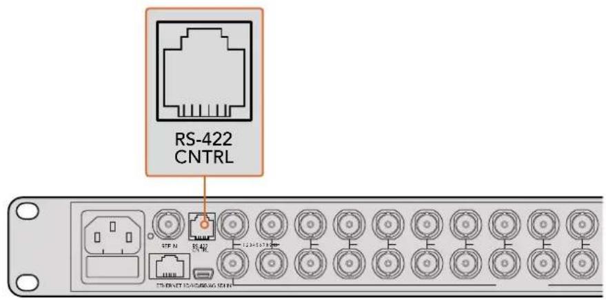
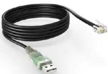
RS-422 CNTRL S1F N 转接 1234578000 STI-PART 60/000000 SEINThe RS-422 serial port lets you control Blackmagic MultiView 16 from third party routers and automation systems. The connector is an RJ11 connector, the same used in many landline telephone connections. By modifying an RS-422 to USB adapter cable terminated with an RJ11 connector, you can control Blackmagic MultiView 16 using external controllers via USB.
natural_image
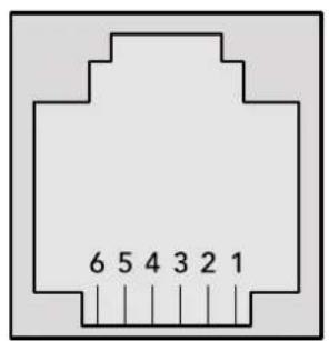
Coiled black USB cable with two Ethernet connectors (no text or symbols visible)An RS-422 to USB adapter cable and RJ11 connector can be purchased from electronics stores such as Digi-Key.com. Refer to the pinout diagram below for help wiring the RJ11 connector to the adapter cable.
| Pin No. Function | |
| Pin 1 | TX + |
| Pin 2 | TX - |
| Pin 3 | GND |
| Pin 4 | GND |
| Pin 5 | RX - |
| Pin 6 | RX + |
text_image
6 5 4 3 2 1Pinout diagram for the RJ11 connector
Notifications
Once connected, if status reporting is enabled, the client will receive a notification message when a route changes on the MultiView. The notifications take one of two forms:
S:0destination,source Routing change
This message indicates that the specified source port is now routed to the specified destination.
V:0destination,source Preset routing notification
This message indicates that the current preset includes a route from the specified source to the specified destination.
Global Commands
All pass through commands are preceded by an Ⓞ symbol and a space.
The following client commands are supported:
@ ! disable status reporting Status reporting is disabled by default.
@ ? enable status reporting Status reporting is enabled.
@ Z: reset routing table
Routing is reset so that the first source is routed to all destinations.
Immediate Commands
@ X:0/destination,source change route
X:0/destination, source/destination-2, source-2... change multiple routes
The specified source ports are routed to the specified destinations.
Any routing changes will trigger S: notifications
@ X?0destination request individual route status
The source routed to the specified destination will be returned as an S: notification.
@ S?0 request all ports route status
Each source and destination port pair will be returned as s: notifications
Salvo Commands
@ P:0/destination,source queue route change
@ P:0/destination, source/destination-2, source-2... queue multiple route changes The specified routing changes are added to the current salvo for later execution.
@ P?0destination request individual port status in salvo If a routing change for the specified destination port is queued, the route will be returned as a V: notification.
@ V?0 request all ports status in salvo Each queued routing change in the salvo is reported as a V: notification.
@ B:C clear salvo
@ B:R clear salvo Any queued changes are discarded and the salvo is reset.
@ B:E execute salvo Any queued changes are executed and each routing change will be returned as an S: notification.
Help
Getting Help
The fastest way to obtain help is to go to the Blackmagic Design online support pages and check the latest support material available for your Blackmagic MultiView.
Blackmagic Design Online Support Pages
The latest manual, software and support notes can be found at the Blackmagic Design support center at www.blackmagicdesign.com/support.
Blackmagic Design Forum
The Blackmagic Design forum on our website is a helpful resource you can visit for more information and creative ideas. This can also be a faster way of getting help as there may already be answers you can find from other experienced users and Blackmagic Design staff which will keep you moving forward. You can visit the forum at https://forum.blackmagicdesign.com
Contacting Blackmagic Design Support
If you can't find the help you need in our support material, or on the forum, please click the "Send us an email" button on the support page to email a support request. Alternatively, click on the "Find your local support team" button and call your nearest Blackmagic Design support office.
Checking the Software Version Currently Installed
To check which version of Blackmagic MultiView software is installed on your computer, open the Blackmagic MultiView application. From the "Blackmagic MultiView" menu, select "About MultiView" and note the version number.
How to get the latest updates
After checking the version of your Blackmagic MultiView on your computer, please visit the Blackmagic Design support center at www.blackmagicdesign.com/support to check for the latest updates. While it is usually a good idea to run the latest updates, it is a wise practice to avoid updating any software if you are in the middle of an important project.
Regulatory Notices and Safety Information
Regulatory Notices
Disposal of waste of electrical and electronic equipment within the European union.

The symbol on the product indicates that this equipment must not be disposed of with other waste materials. In order to dispose of your waste equipment, it must be handed over to a designated collection point for recycling. The separate collection and recycling of your waste equipment at the time of disposal will help conserve natural resources and ensure that it is recycled in a manner that protects human health and the environment. For more information about where you can drop off your waste equipment for recycling, please contact your local city recycling office or the dealer from whom you purchased the product.

This equipment has been tested and found to comply with the limits for a Class A digital device, pursuant to Part 15 of the FCC rules. These limits are designed to provide reasonable protection against harmful interference when the equipment is operated in a commercial environment. This equipment generates, uses, and can radiate radio frequency energy and, if not installed and used in accordance with the instructions, may cause harmful interference to radio communications. Operation of this product in a residential area is likely to cause harmful interference, in which case the user will be required to correct the interference at personal expense.
Operation is subject to the following two conditions:
1 This device may not cause harmful interference.
2 This device must accept any interference received, including interference that may cause undesired operation.
Connection to HDMI interfaces must be made with high quality shielded HDMI cables.
Safety Information
This equipment must be connected to a mains socket outlet with a protective earth connection.
To reduce the risk of electric shock, do not expose this equipment to dripping or splashing.
This equipment is suitable for use in tropical locations with an ambient temperature of up to 40^ C.
Ensure that adequate ventilation is provided around the product and is not restricted.
When rack mounting, ensure the ventilation is not restricted by adjacent equipment.
No operator serviceable parts inside. Refer servicing to your local Blackmagic Design service centre.

Use only at altitudes not more than 2000m above sea level.
Warranty
Limited Warranty
Blackmagic Design warrants that Blackmagic MultiView will be free from defects in materials and workmanship for a period of 36 months from the date of purchase excluding connectors, cables, cooling fans, fiber optic modules, fuses, keyboards and batteries which will be free from defects in materials and workmanship for a period of 12 months from the date of purchase. If a product proves to be defective during this warranty period, Blackmagic Design, at its option, either will repair the defective product without charge for parts and labor, or will provide a replacement in exchange for the defective product.
In order to obtain service under this warranty, you the Customer, must notify Blackmagic Design of the defect before the expiration of the warranty period and make suitable arrangements for the performance of service. The Customer shall be responsible for packaging and shipping the defective product to a designated service center nominated by Blackmagic Design, with shipping charges pre paid. Customer shall be responsible for paying all shipping changes, insurance, duties, taxes, and any other charges for products returned to us for any reason.
This warranty shall not apply to any defect, failure or damage caused by improper use or improper or inadequate maintenance and care. Blackmagic Design shall not be obligated to furnish service under this warranty: a) to repair damage resulting from attempts by personnel other than Blackmagic Design representatives to install, repair or service the product, b) to repair damage resulting from improper use or connection to incompatible equipment, c) to repair any damage or malfunction caused by the use of non Blackmagic Design parts or supplies, or d) to service a product that has been modified or integrated with other products when the effect of such a modification or integration increases the time or difficulty of servicing the product. THIS WARRANTY IS GIVEN BY BLACKMAGIC DESIGN IN LIEU OF ANY OTHER WARRANTIES, EXPRESS OR IMPLIED. BLACKMAGIC DESIGN AND ITS VENDORS DISCLAIM ANY IMPLIED WARRANTIES OF MERCHANTABILITY OR FITNESS FOR A PARTICULAR PURPOSE. BLACKMAGIC DESIGN'S RESPONSIBILITY TO REPAIR OR REPLACE DEFECTIVE PRODUCTS IS THE WHOLE AND EXCLUSIVE REMEDY PROVIDED TO THE CUSTOMER FOR ANY INDIRECT, SPECIAL, INCIDENTAL OR CONSEQUENTIAL DAMAGES IRRESPECTIVE OF WHETHER BLACKMAGIC DESIGN OR THE VENDOR HAS ADVANCE NOTICE OF THE POSSIBILITY OF SUCH DAMAGES. BLACKMAGIC DESIGN IS NOT LIABLE FOR ANY ILLEGAL USE OF EQUIPMENT BY CUSTOMER. BLACKMAGIC IS NOT LIABLE FOR ANY DAMAGES RESULTING FROM USE OF THIS PRODUCT. USER OPERATES THIS PRODUCT AT OWN RISK.
Copyright 2018 Blackmagic Design. All rights reserved. 'Blackmagic Design', 'DeckLink', 'HDLink', 'Workgroup Videohub', 'Multibridge Pro', 'Multibridge Extreme', 'Intensity' and 'Leading the creative video revolution' are registered trademarks in the US and other countries. All other company and product names may be trademarks of their respective companies with which they are associated.