
EXD 2532 - Switch KATHREIN - Free user manual and instructions
Find the device manual for free EXD 2532 KATHREIN in PDF.


| Product Type | Loop-through Multi-Switch (dCSS) |
| Model | EXD 2532 |
| Order Number | 20510105 |
| Number of User Bands | Up to 32 (16+16 or 30+Legacy) |
| Inputs | 1 x terrestrial (5-862 MHz), 4 x Sat (300-2350 MHz) |
| Output Level (Sat AGC) | 94 dBµV |
| Max. Remote Feed Current per Trunk | 1000 mA |
| Power Supply | Optional NCF 18 (100-240 V AC, 18 V DC output) or remote feeding from receiver (12-14 V, 20 mA max without PSU, 450 mA with PSU) |
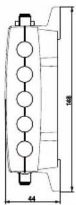
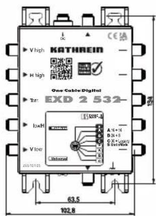
| Dimensions (W x H x D) | 111.5 x 148 x 44 mm |
| Weight | 0.4 kg per unit |
| Protection Class | IP 30 |
| Permissible Ambient Temperature | -20 to +55 °C |
| Installation | Indoor only, wall mounting required |
| Compliance | EN 50494, EN 50607 (SCD2), DiSEqC |
| Special Features | Kathrein Power Saving, PIN code protection, static mode with user band editor, Full-Band Capture, AGC, cascadable up to 8 units |
| LED Indicators | Green (LNB powered), Red (single-cable command received) |
| Maintenance | Wipe with a dry cloth; no liquid cleaners |
| Safety | Must be earthed (Cu, >=4 mm²); unused ports terminated with 75 Ω resistors |
| Spare Parts / Repairability | No user-serviceable parts; professional repair only |
Frequently Asked Questions - EXD 2532 KATHREIN
User questions about EXD 2532 KATHREIN
0 question about this device. Answer the ones you know or ask your own.
Ask a new question about this device
Download the instructions for your Switch in PDF format for free! Find your manual EXD 2532 - KATHREIN and take your electronic device back in hand. On this page are published all the documents necessary for the use of your device. EXD 2532 by KATHREIN.
USER MANUAL EXD 2532 KATHREIN

EXD 1532, BN: 20510104/EXD 2532, BN: 20510105
Sat IF Distribution System (4 x Sat IF) Digital Single-Cable Multi-Switch
About This Guide
This document is part of the product.
▶ Do not install or use the device until you have read and understood this document.
▶ Keep this document for reference throughout the service life of the device. Pass this document on to any new owner or user.
For the most up-to-date version of this document, go to www.kathrein-ds.com.
Features
- Third-generation single-cable multi-switch – digital channel-stacking switch (dCSS) with the newest Full-Band Capture technology
■ Cascadable twin multi-switch. For both outputs, various configurations/numbers of user bands can be selected using the rotary switch
■ 32 user bands (16 + 16) on two outputs for maximal operational reliability and lean distribution
■ Max. 30 user bands on one output, legacy function on the second output
■ Static mode: 27 transponders pre-set with channels, operation without DiSEqC possible
■ User band editor for programming in static mode (download from www.kathrein-ds.com)
■ PIN code: User frequency protection from being accessed by another user. This enables installation across more than one residence

■ EN 50494 single-cable command set and the new, extended EN 50607 (SCD 2) command set are supported
■ Future-proof due to wideband technology (broadband inputs); two satellite positions are possible using two wideband LNBs
■ The integrated AGC (Automatic Gain Control) ensures that the Sat IF signals have a constant output level and more reserve in the distribution
■ Multi-tuner devices can be supplied with a multitude of user bands on one drop cable
■ Up to eight multi-switches can be cascaded
■ Due to the energy-saving concept, the multi-switch consumes no energy from the NCF 18 if all receivers are switched off. If Kathrein Power Saving is active, the power supply for the LNB is also turned off
■ LED as an installation aid and for trouble-shooting
■ For indoor installation
Scope of Delivery Transport and Sto
EXD 1532 • EXD 1532
- NCF 18
- Instructions for Use
EXD 2532 • EXD 2532
- Instructions for Use
EXD 1532
■ Configurable single-cable multi-switch for up to 32 user bands, static mode and external power supply unit for the LNB supply
■ Kathrein Power Saving can be selected and switched off using the rotary switch
NCF 18
■ Highly efficient, short-circuit-proof switched-mode power supply unit
EXD 2532
- Configurable loop-through multi-switch to extend the system by two single-cable connections for up to 32 user bands or static mode
■ Kathrein Power Saving: As soon as there are no longer any receivers active, a signal is generated at the last multi-switch via the vertical low trunk. This signal then switches the LNB power supply off
■ Optional power supply of the multi switch using the NCF 18 (LNB is not supplied!)
e
▶ Transport and store the device in its original packaging.
▶ Make sure there is no water condensation build-up.
Simplified EU Declaration of Conformity
Hereby, KATHREIN Digital Systems GmbH declares that the radio equipment types EXD 1532, order no.: 20510104/EXD 2532, order no.: 20510105
is in compliance with Directive 2014/53/EU. The full text of the EU declaration of conformity is available at the following internet address: www.kathrein-ds.com
Installation Instructions

The devices described are intended solely for the installation in satellite receiver systems and may only be installed by trained specialist personnel.
▶ Any other use, or failure to comply with these instructions, will result in voiding of warranty cover.
The equipments may only be installed in dry indoor areas. Do not install on or against highly combustible materials.
The equipments must be provided with an earthing wire (Cu, at least 4 mm 2 ).
The safety regulations set out in the current EN 60728-11 and EN 62368-1 standards must be complied with.
▶ Fasteners for concrete substrates and masonry: 4 suitable plugs and associated screws with half-round or cylindrical head, outer thread diameter 4.5 - 5 mm, head diameter ≥ 9 mm and a screw length ≥ 30 mm For other types of wall, use the appropriate screws or screw-dowel systems, which offer the same or better fastening
▶ Connector: RF plug 75 Ω (series F) to EN 61169-24.
▶ Unused subscriber ports should be closed off with 75 Ω resistors (e.g. EMK 03).
▶ To meet EMC requirements, the only power supply unit allower to be used is the NCF 18.

Risk of damage to property!
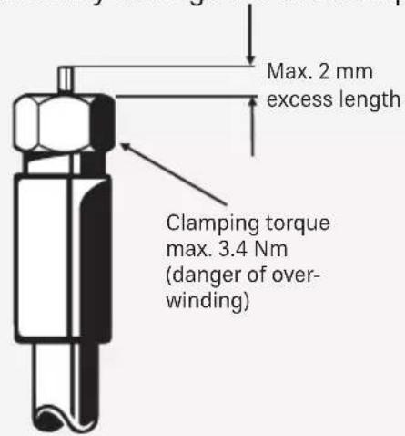
An inner cable conductor with a diameter greater than 1.2 mm, or the presence of burrs may damage the device inputs/outputs beyond repair.

Safety Instructions
Current-carrying device NCF 18

WARNING
Danger to life due to electric shock!
▶ Do not open the unit or tamper with it.
▶ When working on the system, always unplug the power supply unit from the wall socket.
The device is intended only for wall mounting.
All other installation positions are prohibited.
▶ Ensure adequate clearance. Clearance all round must be at least 5 cm.
Risk of overheating! Make sure there is free circulation of air to dissipate the heat from the unit.
▶ Operate the device/power supply unit only in the permissible ambient temperature range of -20 to +55 °C.

CAUTION
▶ No liquid-filled items may be placed on top of the power supply unit.
The power supply unit must not be exposed to dripping or splashing water.
▶ Ensure that the power supply unit is easily accessible and operable.
▶ Disconnect the unit from the mains by pulling the plug of the power supply unit out of the mains socket.
Notes

Only use splitters with no diodes (EBC 110 or EBC 114). The required diode protection is provided by outlets of the ESU series.
It is especially important to make sure that each user band is assigned only once, since otherwise the receivers will generate mutual interference.
The frequencies are assigned on the setting menu of the receiver or TV.
Depending on the type, this assignment may be performed manually or automatically.
It is recommended to assign those outlets with the shorter length connections to the higher frequencies.
By definition, the system is designed so that single-cable devices are supplied with 14 V DC. The power supply is briefly switched to 18 V DC if DiSEqC™ control signals have to be transmitted. Continuous application of 18 V would block the system. For this reason, we recommend the use of the ESU series outlets which are equipped with an electronic switch-off system.
The connected devices with the EN 50494 single-cable standard can use user bands 1 – 8. To be able to exploit all user bands, the receiving device must comply with the new single-cable SCD2 standard according to EN 50607.
Input Frequency Ranges of the Multi-Switch
Depending on the connected LNB, there are two input frequency ranges:
Universal
In case of a universal LNB, the four levels (VL, VH, HL, HH) of the LNB are connected to the inputs of the multi-switch. The LNB supply voltage is provided at the HL input.
Wideband
A wideband LNB has an extended frequency range (300 – 2350 MHz), therefore, only two inputs per satellite are necessary. In combination with two wideband LNBs, the multi-switch can operate two satellite positions. The VL and HL inputs are assigned to position A, the VH and HH inputs to position B. If only one wideband LNB is connected to the multi-switch, it is necessary to use the VL and HL inputs.
In addition, an LNB supply voltage is provided at the HH input in all positions marked in black.
If only one satellite position is used, it is necessary to terminate all the inputs which are not in use with DC-decoupled resistors (e.g. EMK 05).
Rotary Switch
The rotary switch is the central element of the multi-switch. It sets the operation mode and functionality.
The rotary switch is divided into the left and the right half:
If the rotary switch is set to a mode on the left, Kathrein Power Saving is off, i.e. the LNB is powered permanently.
If the rotary switch is set to a mode on the right, Kathrein Power Saving is active and the LNB is switched on only if at least one receiver in the system is active.
In the factory default setting, Kathrein Power Saving is turned off.
![graph TD A["A"] --> D["Red Circle"] B["B"] --> D C["C"] --> D E["A"] --> D F["S"] --> D G["C"] --> D H["B"] --> D I["A"] --> D J["S"] --> D K["A"] --> D L["B"] --> D M["C"] --> D N["A"] --> O["Wideband"] P["B"] --> O Q["C"] --> O R["A 16 + 16"] --> O S["B 24 + 8"] --> O T["C 30 + Legacy"] --> O U["S…](/content/2026/05/812387/images/db1d589d3aaad1ad33694eeddcd7b6d753e8b9400ece49622432e05aa24cd029.jpg)

The settings of the rotary switch are effective only if both subscriber outputs are powered off.
▶ Unscrew both connecting cables to interrupt the power supply.
Changes in the configuration during operation can lead to undesirable configurations and malfunction.
▶ Do not alter the configuration during operation.

Multi-switches without Kathrein Power Saving do not give signalling to the end multi-switch. For permanent powering of the LNB, the rotary switch must be turned to the left side.
SAT IF Splitter
| Type Kathrein Power Saving Switch setting | |||
| VWS 2551 A | Amplifier Unrestrictedly usable ON | ||
| EBX 2520 Two-way splitter | Unrestrictedly usable if each trunk is terminated by the Kathrein Power Saving-capable end multi-switch | ON | |
| EAX 2512 | Two-way splitter | Not Kathrein Power Saving-capable | OFF |
| VWS 2500 | Amplifier | BN 20510098 is Kathrein Power Saving-capable; older models are not | ON/OFF |
Modes of the Rotary Switch
Four different modes can be set:
- A: 2 x 16 UBs: 16 user bands each are available on the two outputs
- B: 1 x 24 UBs and 1 x 8 UBs: eight user bands are available on the top output, 24 on the bottom output
- C: 1 x 30 UBs + legacy: 30 user bands are available on the bottom connection, the top connection is a legacy output (14/18 V - 0/22 kHz), for receivers without the single-cable standard
![graph TD A["POWER Saving OFF"] --> B["C"] A --> C["B"] A --> D["A"] A --> E["S"] A --> F["C"] A --> G["B"] A --> H["A"] A --> I["S"] J["ON POWER Saving"] --> K["A"] J --> L["B"] J --> M["C"] N["A 16 + 16"] --> O["A"] N --> P["B"] N --> Q["C"] R["B 24 + 8"] --> S["A"] R --> T["B"] R --> U["C"] V["C 3…](/content/2026/05/812387/images/0d0aa41b25ae0f1db9ca99c5d0a224630ae6557f7dcaab4661462cc0eb833281.jpg)

If the rotary switch is in C mode, the bandwidth of the user band is 40 MHz. There may be satellites that send transponders with a bandwidth greater than 40 MHz. Reception of such transponders may be disturbed or impossible.
• S (Static Mode): For a detailed description, see s. 8.
PIN Code Protection
To prevent the set user band from being used or disturbed by another subscriber, the multi-switch is protected by a PIN code. The PIN code must be entered in the settings of the receiver or TV (if supported). Each user band is assigned a fixed PIN.
| UB 1 | UB2 | UB3 | UB4 | UB5 | UB6 | UB7 | UB8 | UB9 | UB10 | UB11 | UB12 | UB13 | UB14 | UB15 |
| 151 0 | 52 133 | 124 205 | 196 187 | 178 0 | 99 232 | 198 11 | 190 00 | 2 201 | ||||||
| UB16 | UB17 | UB18 | UB19 | UB20 | UB21 | UB22 | UB23 | UB24 | UB25 | UB26 | UB27 | UB28 | UB29 | UB30 |
| 140 0 | 22 136 | 227 177 | 044 123 | 210 097 | 125 206 | 07 2 248 | 192 003 |
Frequency Assignment of Different User Bands in Modes A, B and C
| 30 UB 24 | UB 16 UB 8 | UB | Location | |||
| Bottom Connec-tion | Top Connection | |||||
| UB 1 970 | MHz 975 M | Hz 975 MHz | 975 MHz | |||
| UB 2 1010 | MHz 1025 | MHz 1025 M | Hz 1025 MHz | |||
| UB 3 1050 | MHz 1075 | MHz 1075 M | Hz 1075 MHz | |||
| UB 4 1090 | MHz 1125 | MHz 1125 MHz | 1125 MHz | |||
| UB 5 1130 | MHz 1175 | MHz 1175 MHz | 1175 MHz | |||
| UB 6 1170 | MHz 1225 | MHz 1225 MHz | 1225 MHz | |||
| UB 7 1210 | MHz 1275 | MHz 1275 MHz | 1275 MHz | |||
| UB 8 1250 | MHz 1325 | MHz 1325 MHz | 1325 MHz | |||
| UB 9* | 1290 MHz | 1375 MHz | 1375 MHz | |||
| UB 10 130 | MHz 1425 | MHz 1425 MHz | ||||
| UB 11 1370 | MHz 1475 | MHz 1475 MHz | ||||
| UB 12 | 1410 MHz | 1525 MHz | 1525 MHz | |||
| UB 13 1450 | MHz 1575 | MHz 1575 MHz | ||||
| UB 14 1490 | MHz 1625 | MHz 1625 MHz | ||||
| UB 15 1530 | MHz 1675 | MHz 1675 MHz | ||||
| UB 16 | 1570 MHz | 1725 MHz | 1725 MHz | |||
| UB 17 | 1610 MHz | 1775 MHz | ||||
| UB 18 1650 | MHz 1825 MHz | |||||
| UB 19 1690 | MHz 1875 MHz | |||||
| UB 20 | 1730 MHz | 1925 MHz | ||||
| UB 21 | 1770 MHz | 1975 MHz | ||||
| UB 22 1810 | MHz 2025 MHz | |||||
| UB 23 | 1850 MHz | 2075 MHz | ||||
| UB 24 | 1890 MHz | 2125 MHz | ||||
| UB 25 | 1930 MHz | |||||
| UB 26 | 1970 MHz | |||||
| UB 27 | 2010 MHz | |||||
| UB 28 | 2050 MHz | |||||
| UB 29 | 2090 MHz | |||||
| UB 30 | 2130 MHz | |||||
* SCD 2 is necessary starting from UB 9
Static Mode
In this mode, up to 32 user bands can be fixedly pre-set with transponders.
As supplied to customer, there are 23 transponders pre-selected that your TV or receiver can find without single-cable control, as these transponders are available at the output in the original frequency range.
Four other, converted, transponders are also available and can be found by running a manual search.
| Frequency in MHz | Polarisation Symbol rate | Error correction |
| 11994 H 27500 3/4 | ||
| 12034 H 22000 2/3 | ||
| 12070 H 27500 3/4 | ||
| 11785 H 22000 3/4 |
The following channels are available to your receiver:
| 1-2-3.tv HD Kabel Eins ProSieben HD* SPORT1 HD* | |||
| 3sat Kabel Eins Doku QVC HD SR HD | |||
| ANIXE HD Kabel Eins Doku HD* QVC ZWEI HD | Super RTL | ||
| ARD alpha HD | Kabel Eins HD* | Radio Bremen HD SWR BW | |
| arte HD | Kabel Eins HD Austria* | rbb | SWR HD |
| AstroTV | KiKA | rbb HD | tagesschau24 HD |
| AstroTV HD MDR RiC | TELE 5 | ||
| Baden TV | MDR HD | RTL 2 | TELE 5 HD* |
| Bloomberg Europe TV | Mei Musi | RTL 2 HD* | TELE 5 HD Austria* |
| BR | NDR | RTL HD* | TOGGO plus |
| BR HD | NDR HD | RTL Television VOX | |
| Comedy Central | Nick/Comedy Central | RTLup VOX HD* | |
| Das Erste | NITRO | RTLup HD* | VOXup HD* |
| Das Erste HD | NITRO Austria | SAT.1 | WDR |
| Disney Channel HD* | ntv SAT.1 Gold | WDR HD | |
| DMAX | ntv Austria SAT.1 HD* | WELT | |
| DMAX HD* ntv HD* | ServusTV Welt der Wunder | ||
| HITRADIO OE3 | ONE HD | ServusTV HD | Welt HD* |
| hr-fernsehen | ORF2E | SIXX HD* ZDF | |
| hr-fernsehen HD | PHOENIX HD | Sky News Intl ZDF HD | |
| HSE Extra HD | Pro7 MAXX | Sonnenklar TV | zdf_neo |
| HSE HD | Pro7 MAXX HD* | Sonnenklar.TV HD | zdf_neo HD |
| Kabel 1 Doku HD Austria* | ProSieben SPORT1 ZDFinfo | ||
The following channels are additionally available by running a manual search:
| 3sat HD KiKA HD RTL Austria VOX Austria | ||
| Euronews NITRO HD* RTL HD Austria* VOX HD Austria* | ||
| Eurosport 1 RTL 2 Austria Super RTL A VOXup | ||
| HSE Extra RTL 2 HD Austria* SUPER RTL HD* ZDFinfo HD |
* You need a valid HD+ subscription for each receiver to receive these channels.
Bear in mind that in static mode your multi-switch behaves similar to a headend and that the transponders can no longer be selected by means of a single-cable command from your TV or receiver.
The transponders/channels are present “statically” at the output. The multi-switch always makes them available without control signals and receiver voltage. This enables a satellite distribution with the same degrees of freedom as a single-cable unit. Depending on the building’s structure, the distribution can be a star-type, tree-type or mixed distribution. The multi-switch does not require remote feeding. Only the distribution losses and level ratios must be observed. As there is no assignment to a user band, a virtually unlimited number of receivers can be connected.

NOTE
For systems with static mode, the receivers must not be in single-cable mode. For reception, set your device to "DiSEqC 1.0" or "simple LNB", for example. If possible and if supported by your device, run a complete search (blind scan). All receivable channels will then be listed.
NOTE
If the EXD 2532 is used in static mode, an NCF 18 must be connected for local power supply!
User Band Editor
If you are not satisfied with the pre-set channel selection, there are optimised channel lists for Austria, Switzerland or Sky, for example.
These channel lists can be installed in the multi-switch using the SWP 50 programming device in connection with the free Kathrein Userband Editor software. For more information on the programming device and the software go to www.kathrein-ds.com.
After programming the multi-switch, it is imperative to run a blind scan on the receiver so that the available channels can be found.
System Example (Symbolic Representation)
![graph TD A["UAS 584/585"] --> B["ExD 2532"] B --> C["ESU 51"] B --> D["ESU 57"] B --> E["ESU 56"] B --> F["ESU 51"] B --> G["ESU 57"] B --> H["ESU 56"] B --> I["ESU 53"] B --> J["ESU 53"] B --> K["ESU 53"] B --> L["ESU 57"] B --> M["ESU 56"] B --> N["ESU 51"] B --> O["ESU 57"] B --> P["ESU 56"] B --…](/content/2026/05/812387/images/41e0bd6bd35242740919469db5aef7a311ea7b5c87ff2aba3f7c734a0b972b4b.jpg)
ESU 5er-Series
The new programmable Single-cable Outlets for apartment across installation.
Further information at
www.kathrein-ds.com/produkte
Technical Data
| Type EXD 1532 EXD 2532 | |||||
| Order no. 20510104 20510105 | |||||
| Subscriber connections Up to 32 Up to 32 | |||||
| Inputs 1 x terr. 4 x Sat 1 x terr. 4 x Sat | |||||
| Frequency range MHz 5 - 862 300 - 2350 | 5 - 862 | 300 - 2350 | |||
| Through loss dB - | 3 | 1.5 | |||
| Connection loss (terrestrial) | dB | 11 | - | 11 | - |
| Sat (AGC) output level | dBμV | - | 94 | - | 94 |
| Horiz./vert. decoupling | dB | - | 30 | - | 30 |
| Trunk decoupling | dB | - | - | - | 40 |
| Sat input level | dBμV | - | 60 - 90 | - | 60 - 90 |
| Subscriber frequency/user band | MHz | see Frequency Assignment of Different User Bands in Modes A, B and C, p. 7 | see Frequency Assignment of Different User Bands in Modes A, B and C, p. 7 | ||
| Permissible supply voltage at the subscriber output | V | 12 - 14 | 12 - 14 | ||
| Max. current consumption at the subscriber connection | mA | 20 | With PSU 20 Without PSU 450 | ||
| Max. permissible voltage at the subscriber connection | V | 19 | 19 | ||
| Max. permissible remote feed current (horiz. low input) | mA | 500(2x 250 for wideband) | - | ||
| Max. permissible remote feed current per trunk | mA | - | 1000 | ||
| Max. supply voltage at DC connection | V | 18.6 | 18.6 (optional) | ||
| Protection class | IP 30 | IP 30 | |||
| Permissible ambient temperature | °C | -20 to +55 | -20 to +55 | ||
| Connections | F connectors | F connectors | |||
| Dimensions | mm | 102.8 x 148 x 44 | 111.5 x 148 x 44 | ||
| Packing unit/weight | pc./kg | 1 (10)/0.51 | 1(10)/0.4 | ||
| Power supply unit NCF 18 | |||||
| Order number | 205500004 | ||||
| Permissible input voltage range | V | 100 - 240 | - | ||
| Nom. input power at 0/150/500 mA load*) | W | 5.4/8.7/15.5 | - | ||
| Secondary voltage (DC) | V | 18 | - | ||
| Protection class | II (double insulated) | ||||
*) All 30 subscriber frequencies/user bands in operation
Possible Causes of Failure and Troubleshooting
There are 2 LEDs near the bottom subscriber connection to be able to narrow down causes of failure:
| LED colour | Signal | Description |
| Green | LED is on | The LNB is powered |
| Red | LED is flashing | The multi-switch has received and understood the single-cable command |
| Problem Possible Cause | Solution | |
| Permanent message: “Poor or no signal” | No voltage from receiver | Make sure there is no short circuit on the receiver - multi-switch connection.The receiver is not in the single-cable mode. |
| Incorrect operation mode | Frequency range, user bands or static mode on the receiver and multi-switch must match. If a setting is changed by means of the rotary switch, briefly disconnect the multi-switch from the mains to apply the new settings after the restart. | |
| Incorrect single-cable command | The receiver is not in the single-cable mode. | |
| Poor DiSEqCTM signal | Use distribution material without diodes to reduce the power consumption.Use the NCF 18 power supply unit with the EXD 2532. | |
| Incorrect PIN code C | Check or deactivate the PIN code. | |
| Incorrect assign-ment | The user band and frequency do not match. Note: SCR address is smaller than the user band number by 1. | |
| No voltage on the LNB (green LED is off) | Connect the NCF 18 power supply unit to the EXD 1532.Make sure there is no short circuit on the multi-switch - LNB connection (if necessary, set Kath-rein Power Saving to “OFF”). | |
| Interconnect DC block EMU 12 (order no. 273281) at the “V low” input of the first loop-through multi-switch. | ||
| Only for UB > 8: “Poor or no signal” | Receiver does not support SCD2 according to EN 50607 | If possible, perform a software update on the receiver or use a lower user band. |
| Short message: “Poor or no signal” or picture stutters at regular intervals. | Another subscriber has accessed the same user band | Check the menu settings of all connected receivers.Make sure that the frequencies are assigned to one receiver only. For a secure installation, use the programmable outlet ESU 5x. |
| Loop-through multi-switches without Kath-rein Power Saving do not function or function only sometimes | Rotary switch is set to Kathrein Power Saving “ON” | Switch off Kathrein Power Saving. Set the rotary switch to “OFF”. |

Electronic equipment
Electronic equipment is not domestic waste – in accordance with directive 2012/19/EU OF THE EUROPEAN PARLIAMENT AND THE COUNCIL dated 4th July 2012 concerning used electrical and electronic appliances, it must be disposed of properly. At the end of its service life, take this unit for disposal at a designated public collection point.
www.kathrein-ds.com | support@kathrein-ds.com
9364964/g/MK/0423/GB | Subject to change.


- SAT IF DISTRIBUTION SYSTEM (4 X SAT IF) DIGITAL SINGLE-CABLE MULTI-SWITCH
- ABOUT THIS GUIDE
- FEATURES
- SCOPE OF DELIVERY TRANSPORT AND STO
- EXD 1532
- NCF 18
- EXD 2532
- E
- SIMPLIFIED EU DECLARATION OF CONFORMITY
- INSTALLATION INSTRUCTIONS
- RISK OF DAMAGE TO PROPERTY
- SAFETY INSTRUCTIONS
- CURRENT-CARRYING DEVICE NCF 18
- WARNING
- DANGER TO LIFE DUE TO ELECTRIC SHOCK
- CAUTION
- NOTES
- UNIVERSAL
- WIDEBAND
- ROTARY SWITCH
- MODES OF THE ROTARY SWITCH
- PIN CODE PROTECTION
- STATIC MODE
- NOTE
- USER BAND EDITOR
- ESU 5ER-SERIES
- ELECTRONIC EQUIPMENT
Brand : KATHREIN
Model : EXD 2532
Category : Switch