
DS-K2800 - Système de contrôle d'accès sécurisé Hikvision - Free user manual and instructions
Find the device manual for free DS-K2800 Hikvision in PDF.


| Product Type | 4-Door Access Controller |
| Brand | Hikvision |
| Model | DS-K2800 |
| Dimensions (W × D × H) | 305 mm × 200 mm × 42 mm |
| Weight | 1.2 kg |
| Power Supply | 12 VDC, 3 A |
| Power Consumption | ≤ 12 W |
| Operating Temperature | -10 °C to 55 °C |
| Operating Humidity | 10% to 90% (non-condensing) |
| Network Interface | 1 × 10/100 Mbps Ethernet |
| Card Capacity | 50,000 cards |
| Event Capacity | 100,000 events |
| Supported Readers | Wiegand (26/34 bit) and RS-485 |
| Door Control | 4 doors (input/output each) |
| Relay Output | 4 × dry contact relays (NC/NO) |
| Tamper Protection | Tamper switch included |
| Protection Level | IP30 |
| Operating System | Embedded Linux |
| Software Compatibility | HikCentral, iVMS-4200, Hik-Connect |
| Mounting | Wall mount or DIN rail |
| Certifications | CE, FCC, RoHS |
| Maintenance | Keep clean and dry; check connections periodically |
| Security Features | Anti-passback, multi-card authentication, tamper alert |
| Spare Parts and Repairability | Power supply, relay board, mainboard available; field replaceable |
Frequently Asked Questions - DS-K2800 Hikvision
User questions about DS-K2800 Hikvision
0 question about this device. Answer the ones you know or ask your own.
Ask a new question about this device
Download the instructions for your Système de contrôle d'accès sécurisé in PDF format for free! Find your manual DS-K2800 - Hikvision and take your electronic device back in hand. On this page are published all the documents necessary for the use of your device. DS-K2800 by Hikvision.
USER MANUAL DS-K2800 Hikvision
DS-K2800 Series Access Controller
User Manual
User Manual
© 2018 Hangzhou Hikvision Digital Technology Co., Ltd.
This manual is applied for access controller.
| Product Name | Serials |
| Access Controller | DS-K2801 Serials Access Controller |
| DS-K2802 Serials Access Controller | |
| DS-K2804 Serials Access Controller |
It includes instrucons on how to use the Product. The soware embodied in the Product is governed by the user license agreement covering that Product.
About this Manual
This Manual is subject to domesc and internaonal copyright protecon. Hangzhou Hikvision Digital Technology Co., Ltd. ("Hikvision") reserves all rights to this manual. This manual cannot be reproduced, changed, translated, or distributed, parally or wholly, by any means, without the prior written permission of Hikvision.
Trademarks
HIKVISION and other Hikvision marks are the property of Hikvision and are registered trademarks or the subject of applicaons for the same by Hikvision and/or its aliases. Other trademarks menoned in this manual are the properes of their respective owners. No right of license is given to use such trademarks without express permission.
Disclaimer
TO THE MAXIMUM EXTENT PERMITTED BY APPLICABLE LAW, HIKVISION MAKES NO WARRANTIES, EXPRESS OR IMPLIED, INCLUDING WITHOUT LIMITATION THE IMPLIED WARRANTIES OF MERCHANTABILITY AND FITNESS FOR A PARTICULAR PURPOSE, REGARDING THIS MANUAL. HIKVISION DOES NOT WARRANT, GUARANTEE, OR MAKE ANY REPRESENTATIONS REGARDING THE USE OF THE MANUAL, OR THE CORRECTNESS, ACCURACY, OR RELIABILITY OF INFORMATION CONTAINED HEREIN. YOUR USE OF THIS MANUAL AND ANY RELIANCE ON THIS MANUAL SHALL BE WHOLLY AT YOUR OWN RISK AND RESPONSIBILITY.
REGARDING TO THE PRODUCT WITH INTERNET ACCESS, THE USE OF PRODUCT SHALL BE WHOLLY AT YOUR OWN RISKS. OUR COMPANY SHALL NOT TAKE ANY RESPONSIBILITIES FOR ABNORMAL OPERATION, PRIVACY LEAKAGE OR OTHER DAMAGES RESULTING FROM CYBER ATTACK, HACKER ATTACK, VIRUS INSPECTION, OR OTHER INTERNET SECURITY RISKS; HOWEVER, OUR COMPANY WILL PROVIDE TIMELY TECHNICAL SUPPORT IF REQUIRED.
SURVEILLANCE LAWS VARY BY JURISDICTION. PLEASE CHECK ALL RELEVANT LAWS IN YOUR JURISDICTION BEFORE USING THIS PRODUCT IN ORDER TO ENSURE THAT YOUR USE CONFORMS THE APPLICABLE LAW. OUR COMPANY SHALL NOT BE LIABLE IN THE EVENT THAT THIS PRODUCT IS USED WITH ILLEGITIMATE PURPOSES.
IN THE EVENT OF ANY CONFLICTS BETWEEN THIS MANUAL AND THE APPLICABLE LAW, THE LATER PREVAILS.
Support
Should you have any quesons, please do not hesitate to contact your local dealer.
Regulatory Informaon
FCC Informaon
Please take aenon that changes or modicaon not expressly approved by the party responsible for compliance could void the user's authority to operate the equipment.
FCC compliance: This equipment has been tested and found to comply with the limits for a Class B digital device, pursuant to part 15 of the FCC Rules. These limits are designed to provide reasonable protecon against harmful interference in a residential installaon. This equipment generates, uses and can radiate radio frequency energy and, if not installed and used in accordance with the instrucons, may cause harmful interference to radio communicaons. However, there is no guarantee that interference will not occur in a parcular installaon. If this equipment does cause harmful interference to radio or television recepon, which can be determined by turning the equipment o and on, the user is encouraged to try to correct the interference by one or more of the following measures:
—Reorient or relocate the receiving antenna.
—Increase the separaon between the equipment and receiver.
—Connect the equipment into an outlet on a circuit dierent from that to which the receiver is connected.
—Consult the dealer or an experienced radio/TV technician for help.
FCC Conditions
This device complies with part 15 of the FCC Rules. Operaon is subject to the following two conditions:
- This device may not cause harmful interference.
- This device must accept any interference received, including interference that may cause undesired operaon.
EU Conformity Statement

This product and - if applicable - the supplied accessories too are marked with "CE" and comply therefore with the applicable harmonized European standards listed under the R&TTE Direcve 1999/5/EC, the EMC Direcve 2014/30/EU, the LVD Direcve 2014/35/EU, the RoHS Direcve 2011/65/EU.

2012/19/EU (WEEE direcve): Products marked with this symbol cannot be disposed of as unsorted municipal waste in the European Union. For proper recycling, return this product to your local supplier upon the purchase of equivalent new equipment, or dispose of it at designated collection points. For more informaon see: www.recyclethis.info.

2006/66/EC (battery directive): This product contains a baery that cannot be disposed of as unsorted municipal waste in the European Union. See the product documentation for specific baery informaon. The baery is marked with this symbol, which may include leering to indicate cadmium (Cd), lead (Pb), or mercury (Hg). For proper recycling, return the battery to your supplier or to a designated
collecon point. For more informaon see: www.recyclethis.info.
Industry Canada ICES-003 Compliance
This device meets the CAN ICES-3 (A)/NMB-3(A) standards requirements.
Prevenve and Cauonary Tips
Before connecng and operang your device, please be advised of the following ps:
- Ensure unit is installed in a well-venlated, dust-free environment.
- Keep all liquids away from the device.
- Ensure environmental conditions meet factory specicaons.
- Ensure unit is properly secured to a rack or shelf. Major shocks or jolts to the unit as a result of dropping it may cause damage to the sensitive electronics within the unit.
- Use the device in conjuncon with an UPS if possible.
• Power down the unit before connecng and disconnectg accessories and peripherals. - A factory recommended HDD should be used for this device.
Improper use or replacement of the baery may result in hazard of explosion. Replace with the same or equivalent type only. Dispose of used baeries according to the instrucons provided by the manufacturer.
Safety Instrucon
These instrucons are intended to ensure that user can use the product correctly to avoid danger or property loss.
The precauon measure is divided into Warnings and Cauons:
Warnings: Neglecng any of the warnings may cause serious injury or death.
Cauons: Neglecng any of the cauons may cause injury or equipment damage.
| Warnings Follow these safeguards to prevent serious injury or death. | Cauons Follow these precautions to prevent potential injury or material damage. |

Warnings
- All the electronic operaon should be strictly compliance with the electrical safety regulaons, re prevenon regulaons and other related regulaons in your local region.
- Please use the power adapter, which is provided by normal company. The power consumption cannot be less than the required value.
- Do not connect several devices to one power adapter as adapter overload may cause over-heat or re hazard.
- Please make sure that the power has been disconnected before you wire, install or dismantle the device.
- When the product is installed on wall or ceiling, the device shall be rmly xed.
- If smoke, odors or noise rise from the device, turn o the power at once and unplug the power cable, and then please contact the service center.
- If the product does not work properly, please contact your dealer or the nearest service center. Never aempt to disassemble the device yourself. (We shall not assume any responsibility for problems caused by unauthorized repair or maintenance.)

Cauons
- Do not drop the device or subject it to physical shock, and do not expose it to high electromagnesm radiaon. Avoid the equipment installaon on vibraons surface or places subject to shock (ignorance can cause equipment damage).
- Do not place the device in extremely hot (refer to the specicaon of the device for the detailed operang temperature), cold, dusty or damp locaons, and do not expose it to high electromagnec radiaon. The appropriate operaon temperature is 0°C to +45°C, and the storage temperature should be -10°C to +55°C.
● The device cover for indoor use shall be kept from rain and moisture. - Exposing the equipment to direct sun light, low venlaon or heat source such as heater or radiator is forbidden (ignorance can cause re danger).
- Do not aim the device at the sun or extra bright places. A blooming or smear may occur otherwise (which is not a malfuncon however), and aecng the endurance of sensor at the same me.
- Please use the provided glove when open up the device cover, avoid direct contact with the device cover, because the acidic sweat of the ngers may erode the surface coang of the device cover.
- Please use a so and dry cloth when clean inside and outside surfaces of the device cover, do not use alkaline detergents.
- Please keep all wrappers aer unpack them for future use. In case of any failure occurred, you need to return the device to the factory with the original wrapper. Transportaon without the original wrapper may result in damage on the device and lead to additional costs.
- Improper use or replacement of the baery may result in hazard of explosion. Replace with the same or equivalent type only. Dispose of used baeries according to the instrucons provided by the baery manufacturer.
Table of Contents
Chapter 1 Product Descripon ....1
1.1 Overview 1
1.2 Main Features .... 1
Chapter 2 Component Descripon ......2
Chapter 3 Terminal Connecon....3
3.1 DS-K2801 Terminal Descripon....3
3.2 DS-K2802Terminal Descripon....5
3.3 DS-K2804 Terminal Descripon....7
Chapter 4 External Device Wiring ....10
4.1 Card Reader Wiring....10
4.1.1 Wiegand Card Reader Wiring 10
4.1.2 DS-K1800 Series Card Reader Wiring....10
4.2 DS-K2801 External Terminals 10
4.2.1 Installaon of Cathode Lock....11
4.2.2 Installaon of Anode Lock....11
4.3 Connecng the External Alarm Device 12
4.4 Door Buon Wiring Diagram 12
4.5 The Connecon of Magnecs Detecon 13
4.6 Connecng Power Supply 13
Chapter 5 Setngs ......14
5.1 Inializing the Hardware....14
5.2 Relay Input NO/NC 14
5.2.1 Lock Relay Output 14
5.2.2 Alarm Relay Output Status....15
Chapter 6 Acvang the Access Control Terminal....17
6.1 Acvang via SADP Soware 17
6.2 Acvang via Client Soware 18
Chapter 7 Client Operaon ....21
7.1 Funcon Module 21
7.2 User Registraon and Login 21
7.3 System Conguration 22
7.4 Access Control Management 23
7.4.1 Adding Access Control Device 24
7.4.2 Viewing Device Status....33
7.4.3 Eding Basic Informaon 33
7.4.4 Remote Conguraon....33
7.5 Person and Card Management 39
7.5.1 Organizaon Management 39
7.5.2 Person Management....40
7.6 Schedule and Template....48
7.6.1 Week Schedule....49
7.6.2 Holiday Group 50
7.6.3 Template....51
7.7 Permission Conguraon....53
7.7.1 Adding Permission....54
7.7.2 Applying Permission....55
7.8 Advanced Funcons....55
7.8.1 Access Control Parameters....56
7.8.2 Card Reader Authencaon....58
7.8.3 Open Door with First Card 59
7.8.4 An-Passing Back 60
7.8.5 Authencaon Password 62
7.8.6 Custom Wiegand....62
7.9 Searching Access Control Event 64
7.10 Access Control Event Conguraon 65
7.10.1 Access Control Event Linkage 65
7.10.2 Access Control Alarm Input Linkage....67
7.10.3 Event Card Linkage 67
7.10.4 Cross-Device Linkage....69
7.11 Door Status Management....70
7.11.1 Access Control Group Management 70
7.11.2 An-control the Access Control Point (Door)....72
7.11.3 Status Duraon Conguraon 73
7.11.4 Real-me Card Swiping Record....75
7.11.5 Real-me Access Control Alarm....75
7.12 Arming Control....76
Appendix A Sound Prompt and Indicator 78
Appendix B Custom Wiegand Rule....79
Chapter 1 Product Description
1.1 Overview
DS-K2800 is a powerful and stable access controller, using the logical architecture design. DS-K2800 is designed with TCP/IP network interface and its signal processed with special encrypon and can be run oine. An-tampering funcon is also supported.
1.2 Main Features
- The access controller is equipped with 32-bit high-speed processor
- Supports TCP/IP network communicaon, with self-adapve network interface. The communicaon data is specially encrypted to relieve the concern of privacy leak
• Supports recognition and storage of card number with maximum length of 20 - The access controller can store 10 thousand legal cards and 50 thousand card swiping records
- Supports rst card open-door and rst card authorizaon funcon, super card and super password funcon, online upgrade funcon and remote control of the doors
- Supports Wiegand interface for accessing card reader. Wiegand interface supports W26/W34 and is seamlessly compatible with third-party card reader with Wiegand interface
- Supports various card types as normal/ disabled/ blacklist/ patrol/ guest/ duress/ super card, etc.
• Supports me synchronizaon via NTP, manual or automac method - Supports record storage funcon when it is oine and insucient storage space storage alarm funcon
- The access controller has watchdog design
- Data can be permanently saved aer the access controller is powered o.
• Supports I/O linkage, and event linkage
• Supports alarm of oine event exceeding 90% - Mulple event upload methods: channel, center group, and listening
- 500 groups of authencaon code
- An-pass-back funcon.
Chapter 2 Component Description
Take DS-K2804 as an example, the component schemac diagram is shown below.
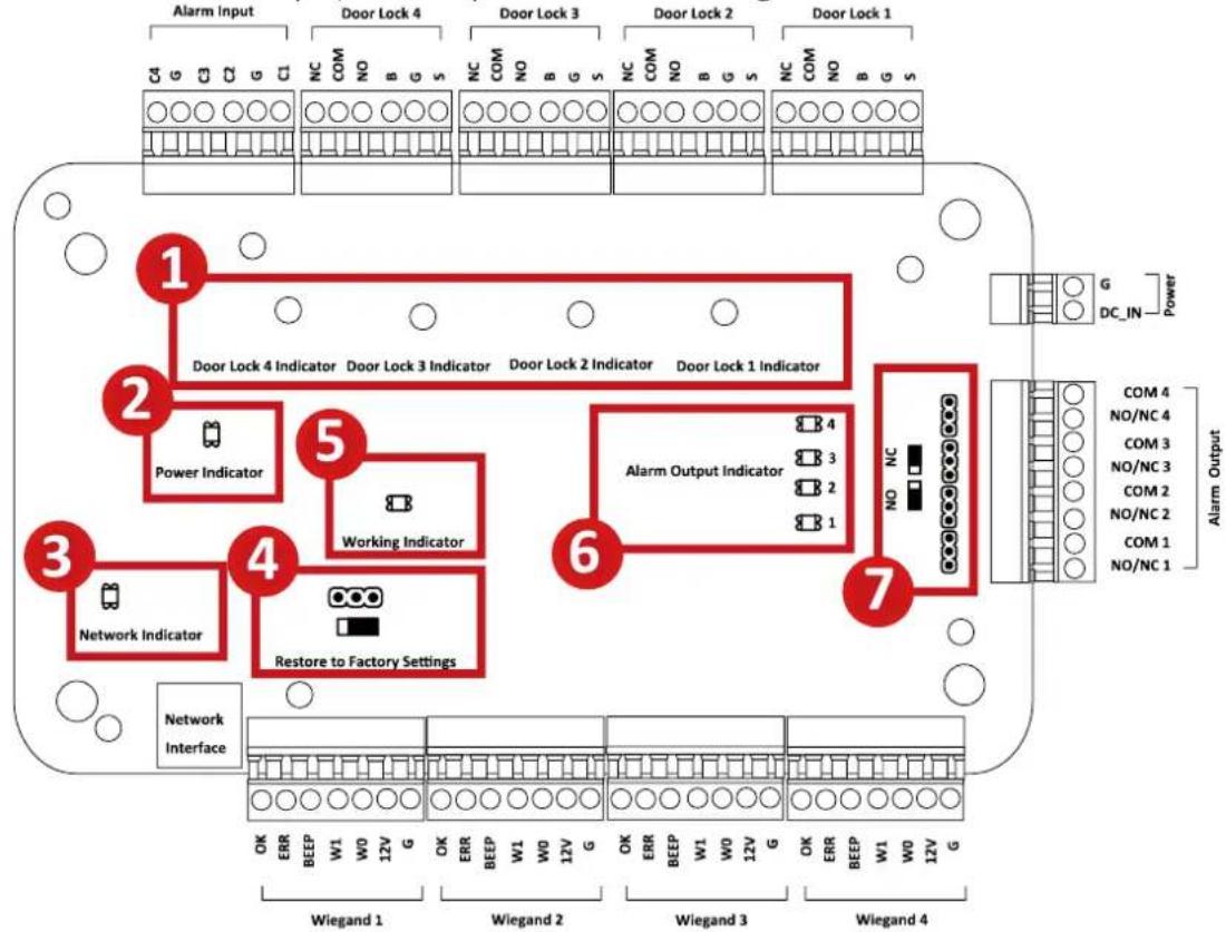
DS-K2800 component descripons are as follows:
| No. | Component Descripon | ||
| DS-K2801 | DS-K2802 | DS-K2804 | |
| 1 | Door Lock 1Indicator | Door Lock 1/2Indicator | Door Lock 1/2/3/4Indicator |
| 2 | Power Indicator | ||
| 3 | Network Indicator | ||
| 4 | Jumper Cap for Restoring Factory Sengs | ||
| 5 | Working Indicator | ||
| 6 | Alarm Output Indicator | ||
| 7 | Alarm Output (NO/NC) Jumper Cap | ||
Chapter 3 Terminal Connection
3.1 DS-K2801 Terminal Description
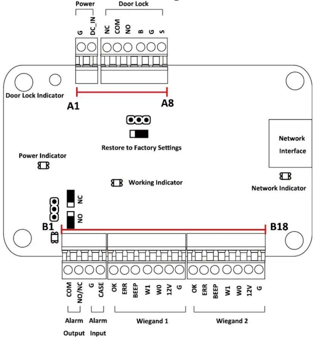
DS-K2801 Terminal descripons are as follows:
| No. | DS-K2801 | ||
| A1 | Power | GND | DC12V Grounding |
| A2 | +12V | DC12V Input | |
| A3 | Door | NC | Door Lock Relay Output |
| A4 | COM | ||
| A5 | NO | ||
| A6 | BUTTON | Door Buon Input | |
| A7 | GND | Grounding | |
| A8 | SENSOR | Door Magnec detector | |
| B1 | Alarm Output | COM | Alarm Relay Output (Dry Contact) |
| B2 | NO/NC | ||
| B3 | Alarm Input | GND | Grounding |
| B4 | IN | Event Input | |
| B5 | Wiegand Card Reader 1 | OK | Indicator of Card Reader Control Output (Valid Card Output) |
| B6 | ERR | Indicator of Card Reader Control Output (Invalid Card Output) | |
| B7 | BZ | Card Reader Buzzer Control Output | |
| B8 | W1 | Wiegand Head Read Data Input Data1 | |
| B9 | W0 | Wiegand Head Read Data Input Data0 | |
| B10 | PWR | Card Reader Power Output | |
| B11 | GND | ||
| B12 | Wiegand Card Reader 2 | OK | Indicator of Card Reader Control Output (Valid Card Output) |
| B13 | ERR | Indicator of Card Reader Control Output (Invalid Card Output) | |
| B14 | BZ | Card Reader Buzzer Control Output | |
| B15 | W1 | Wiegand Head Read Data Input Data1 | |
| B16 | W0 | Wiegand Head Read Data Input Data0 | |
| B17 | PWR | Card Reader Power Output | |
| B18 | GND | ||
3.2 DS-K2802Terminal Description
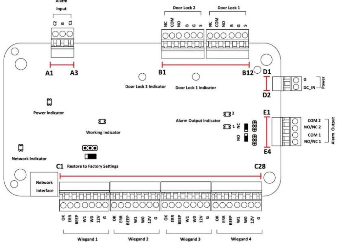
DS-K2802 Terminal descripons are as follows:
| No. | DS-K2802 | ||
| A1 | Alarm Input | IN2 | Event Input 2 |
| A2 | GND | Grounding | |
| A3 | IN1 | Event Input 1 | |
| B1 | Door 2 | NC | Door Lock Relay Output (Dry Contact) |
| B2 | COM | ||
| B3 | NO | ||
| B4 | BUTTON | Door Buon Input | |
| B5 | GND | Grounding | |
| B6 | SENSOR | Door Magnec detector | |
| B7 | Door 1 | NC | Door Lock Relay Output (Dry Contact) |
| B8 | COM | ||
| B9 | NO | ||
| B10 | BUTTON | Door Buon Input | |
| B11 | GND | Grounding | |
| B12 | SENSOR | Door Magnec detector | |
| D1 | Power | GND | DC12V Grounding |
| D2 | +12V | DC12V Input | |
| E1 | Alarm Output 2 | COM2 | Alarm Relay Output 2 (Dry Contact) |
| E2 | NO/NC2 | ||
Access Controller · User Manual
| No. | DS-K2802 | ||
| E3 | Alarm Output 1 | COM1 | Alarm Relay Output 1 (Dry Contact) |
| E4 | NO/NC1 | ||
| C1 | Wiegand Card Reader 1 | OK | Indicator of Card Reader Control Output (Valid Card Output) |
| C2 | ERR | Indicator of Card Reader Control Output (Invalid Card Output) | |
| C3 | BZ | Card Reader Buzzer Control Output | |
| C4 | W1 | Wiegand Head Read Data Input Data1 | |
| C5 | W0 | Wiegand Head Read Data Input Data0 | |
| C6 | PWR | Card Reader Power Output | |
| C7 | GND | ||
| C8 | Wiegand Card Reader 2 | OK | Indicator of Card Reader Control Output (Valid Card Output) |
| C9 | ERR | Indicator of Card Reader Control Output (Invalid Card Output) | |
| C10 | BZ | Card Reader Buzzer Control Output | |
| C11 | W1 | Wiegand Head Read Data Input Data1 | |
| C12 | W0 | Wiegand Head Read Data Input Data0 | |
| C13 | PWR | Card Reader Power Output | |
| C14 | GND | ||
| C15 | Wiegand Card Reader 3 | OK | Indicator of Card Reader Control Output (Valid Card Output) |
| C16 | ERR | Indicator of Card Reader Control Output (Invalid Card Output) | |
| C17 | BZ | Card Reader Buzzer Control Output | |
| C18 | W1 | Wiegand Head Read Data Input Data1 | |
| C19 | W0 | Wiegand Head Read Data Input Data0 | |
| C20 | PWR | Card Reader Power Output | |
| C21 | GND | ||
| C22 | Wiegand Card Reader 4 | OK | Indicator of Card Reader Control Output (Valid Card Output) |
| C23 | ERR | Indicator of Card Reader Control Output (Invalid Card Output) | |
| C24 | BZ | Card Reader Buzzer Control Output | |
| C25 | W1 | Wiegand Head Read Data Input Data1 | |
| C26 | W0 | Wiegand Head Read Data Input Data0 | |
| C27 | PWR | Card Reader Power Output | |
| C28 | GND | ||
3.3 DS-K2804 Terminal Description
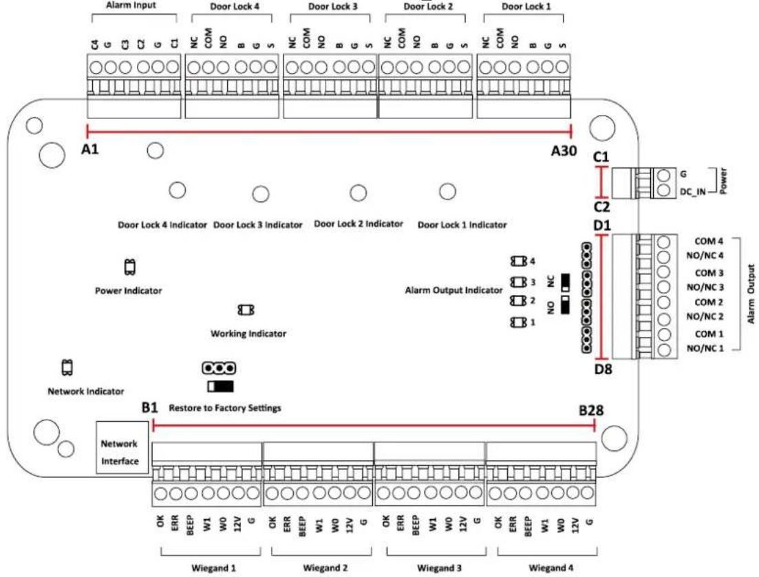
DS-K2804 Terminal descripons are as follows:
| No. | DS-K2804 | ||
| A1 | Alarm Input | IN4 | Event Input 4 |
| A2 | GND | Grounding | |
| A3 | IN3 | Event Input 3 | |
| A4 | IN2 | Event Input 2 | |
| A5 | GND | Grounding | |
| A6 | IN1 | Event Input 1 | |
| A7 | Door 4 | NC | Door Lock Relay Output (Dry Contact) |
| A8 | COM | ||
| A9 | NO | ||
| A10 | BUTTON | Door Buon Input | |
| A11 | GND | Grounding | |
| A12 | SENSOR | Door Magnec detector | |
| A13 | Door 3 | NC | Door Lock Relay Output (Dry Contact) |
| A14 | COM | ||
| A15 | NO | ||
| A16 | BUTTON | Door Buon Input | |
| A17 | GND | Grounding | |
| A18 | SENSOR | Door Magnec detector | |
| A19 | Door 2 | NC | Door Lock Relay Output (Dry Contact) |
| A20 | COM | ||
| A21 | NO | ||
| A22 | BUTTON | Door Buon Input | |
| A23 | GND | Grounding | |
| A24 | SENSOR | Door Magnec detector | |
| A25 | Door 1 | NC | Door Lock Relay Output (Dry Contact) |
| A26 | COM | ||
| A27 | NO | ||
| A28 | BUTTON | Door Buon Input | |
| A29 | GND | Grounding | |
| A30 | SENSOR | Door Magnec detector | |
| B1 | Wiegand Card Reader 1 | OK | Indicator of Card Reader Control Output (Valid Card Output) |
| B2 | ERR | Indicator of Card Reader Control Output (Invalid Card Output) | |
| B3 | BZ | Card Reader Buzzer Control Output | |
| B4 | W1 | Wiegand Head Read Data Input Data1 | |
| B5 | W0 | Wiegand Head Read Data Input Data0 | |
| B6 | PWR | Card Reader Power Output | |
| B7 | GND | ||
| B8 | Wiegand Card Reader 2 | OK | Indicator of Card Reader Control Output (Valid Card Output) |
| B9 | ERR | Indicator of Card Reader Control Output (Invalid Card Output) | |
| B10 | BZ | Card Reader Buzzer Control Output | |
| B11 | W1 | Wiegand Head Read Data Input Data1 | |
| B12 | W0 | Wiegand Head Read Data Input Data0 | |
| B13 | PWR | Card Reader Power Output | |
| B14 | GND | ||
| B15 | Wiegand Card Reader 3 | OK | Indicator of Card Reader Control Output (Valid Card Output) |
| B16 | ERR | Indicator of Card Reader Control Output (Invalid Card Output) | |
| B17 | BZ | Card Reader Buzzer Control Output | |
| B18 | W1 | Wiegand Head Read Data Input Data1 | |
| B19 | W0 | Wiegand Head Read Data Input Data0 | |
| B20 | PWR | Card Reader Power Output | |
| B21 | GND | ||
| B22 | Wiegand Card Reader 4 | OK | Indicator of Card Reader Control Output (Valid Card Output) |
| B23 | ERR | Indicator of Card Reader Control Output (Invalid Card Output) | |
| B24 | BZ | Card Reader Buzzer Control Output | |
| B25 | W1 | Wiegand Head Read Data Input Data1 | |
| B26 | W0 | Wiegand Head Read Data Input Data0 | |
| B27 | PWR | Card Reader Power Output | |
| B28 | GND | ||
| C1 | Power | GND | DC12V Grounding |
| C2 | +12V | DC12V Input | |
| D1 | Alarm Output 4 | COM4 | Alarm Relay Output 4 (Dry Contact) |
| D2 | NO/NC4 | ||
| D3 | Alarm Output 3 | COM3 | Alarm Relay Output 3 (Dry Contact) |
| D4 | NO/NC3 | ||
| D5 | Alarm Output 2 | COM2 | Alarm Relay Output 2 (Dry Contact) |
| D6 | NO/NC2 | ||
| D7 | Alarm Output 1 | COM1 | Alarm Relay Output 1 (Dry Contact) |
| D8 | NO/NC1 | ||
Notes:
- The Alarm input hardware interface is normally open by default. So only the normally open signal is allowed. It can be linked to the buzzer of the card reader and access controller, and the alarm relay output and open door relat output.
- For single-door access controller, the Wiegand card reader 1 and 2 respectively correspond to the entering and exing card readers of door 1. For two-door access controller, the Wiegand card reader 1 and 2 respectively correspond to the entering and exing card readers of door 1, and the Wiegand card reader 3 and 4 respectively correspond to the entering and exing card readers of door 2. For four-door access controller, the Wiegand card reader 1, 2, 3 and 4 respectively correspond to the entering card readers of door 1, 2, 3, and 4.
Chapter 4 External Device Wiring
4.1 Card Reader Wiring
4.1.1 Wiegand Card Reader Wiring
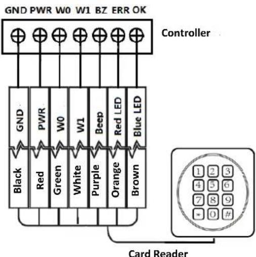
Note: You must connect the OK/ERR/BZ, if using access controller to control the LED and buzzer of the Wiegand card reader.
4.1.2 DS-K1800 Series Card Reader Wiring
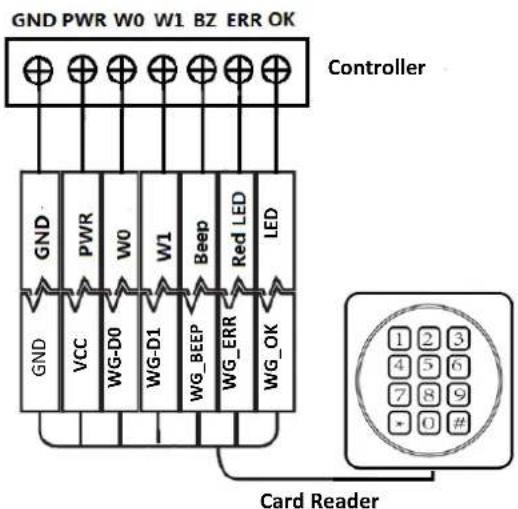
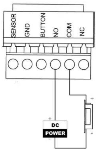
4.2 DS-K2801 External Terminals
4.2.1 Installaon of Cathode Lock
4.2.2 Installaon of Anode Lock
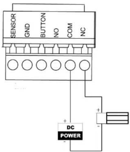
4.3 Connecting the External Alarm Device
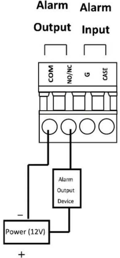
flowchart
graph TD
    A["Power (12V)"] --> B["Alarm Output Device"]
    B --> C["COM NO/NC G CASE"]
    C --> D["+"]
    style A fill:#f9f,stroke:#333
    style B fill:#ccf,stroke:#333
    style C fill:#cfc,stroke:#333
    style D fill:#fcc,stroke:#333
4.4 Door Button Wiring Diagram
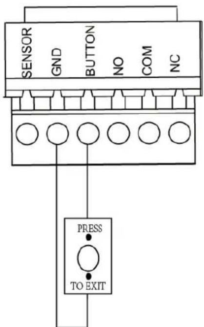
4.5 The Connection of Magnetics Detection
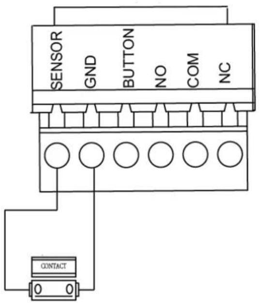
4.6 Connecting Power Supply
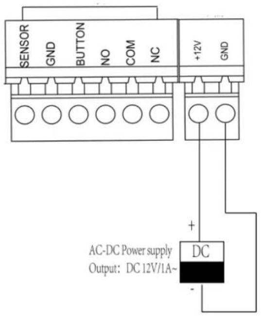
Chapter 5 Settings
5.1 Initializing the Hardware
Opon 1:
Steps:
- Remove the jumper cap from the Normal terminal.
- Disconnect the power and restart the access controller. The controller buzzer buzzes a long beep.
- When the beep stopped, plug the jumper cap back to Normal.
- Disconnect the power and restart the access controller.
Opon 2:
Steps:
- Jump the jumper cap from Normal to Inial.
- Disconnect the power and restart the access controller. The controller buzzer buzzes a long beep.
- When the beep stopped, jump the jumper cap back to Normal.
- Disconnect the power and restart the access controller.

flowchart
graph LR
    A["Normal端"] --> B["●"]
    C["Initial端"] --> D["●"]
    E["JP11"] --> F["◀"]
DS-K2801 Inializaon Dial-up

flowchart
graph LR
    A["Initial端"] --> B["●"]
    B --> C["●"]
    C --> D["●"]
    D --> E["JP11"]
    F["Normal端"] --> B
    G["Normal端"] --> C
    H["Normal端"] --> D
DS-K2802/DS-K2804 Inializaon Dial-up
Note: The inializing of the hardware will restore all the parameters to the default seng and all the device events are wiping out.
5.2 Relay Input NO/NC
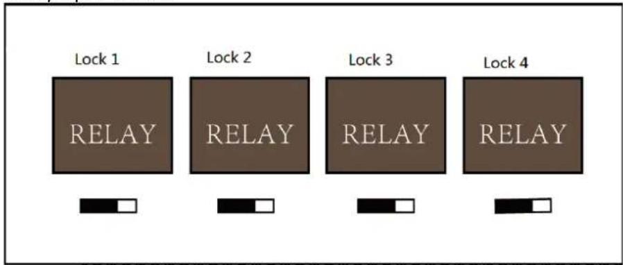
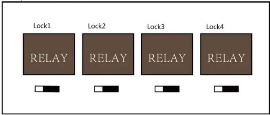
5.2.1 Lock Relay Output
Lock Relay Normally Open Status:
Lock Relay Normally Closed Status:
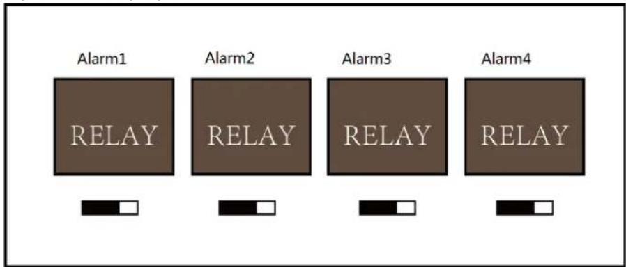
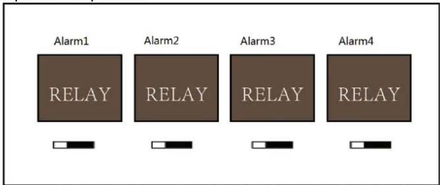
5.2.2 Alarm Relay Output Status
Alarm Relay Output Normally Open:
Alarm Relay Output Normally Closed:
Work Flow of Soware
For detailed informaon, please see the user manual of the client soware.
Refer to the following work ow:
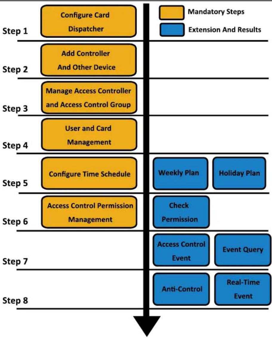
flowchart
graph TD
    A["Configure Card Dispatcher"] --> B["Add Controller And Other Device"]
    B --> C["Manage Access Controller and Access Control Group"]
    C --> D["User and Card Management"]
    D --> E["Configure Time Schedule"]
    E --> F["Access Control Permission Management"]
    F --> G["Check Permission"]
    G --> H["Access Control Event"]
    H --> I["Anti-Control"]
    I --> J["Real-Time Event"]
Chapter 6 Activating the Access Control Terminal
Purpose:
You are required to acvate the terminal rst before using it.
Acvaon via SADP, and Acvaon via client soware are supported.
The default values of the control terminal are as follows.
● The default IP address: 192.0.0.64.
● The default port No.: 8000.
● The default user name: admin.
6.1 Activating via SADP Software
SADP soware is used for detectng the online device, acvang the device, and reseng the password.
Get the SADP soware from the supplied disk, and install the SADP according to the prompts. Follow the steps to acvate the control panel.
Steps:
- Run the SADP soware to search the online devices.
- Check the device status from the device list, and select an inacve device.
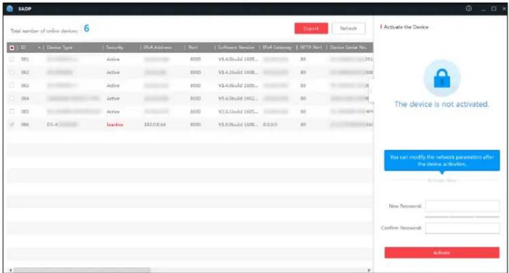
- Create a password and input the password in the password eld, and conrm the password.

STRONG PASSWORD RECOMMENDED— We highly recommend you create a strong password of your own choosing (using a minimum of 8 characters, including upper case leers, lower case leers, numbers, and special characters) in order to increase the security of your product. And we recommend you reset your password regularly, especially in the high security system, reseng the password monthly or weekly can beer protect your product.
- Click Acvate to acvate the device.
- Check the acvated device. You can change the device IP address to the same network
segment with your computer by either modifying the IP address manually or checking the checkbox of Enable DHCP.
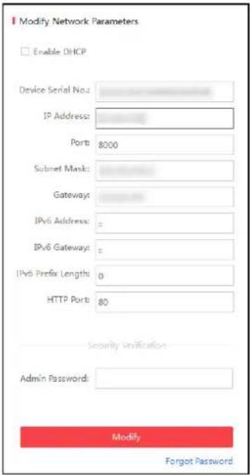
- Input the password and click the Modify buon to acvate your IP address modicaon.
6.2 Activating via Client Software
The client soware is versale video management soware for mulple kinds of devices.
Get the client soware from the supplied disk, and install the soware according to the prompts. Follow the steps to acvate the control panel.
Steps:
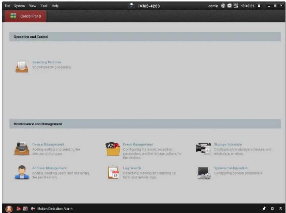
- Run the client soware and the control panel of the soware pops up, as shown in the gure below.
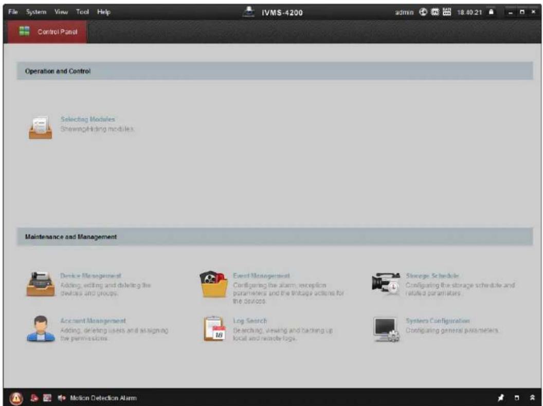
- Click the Device Management to enter the Device Management interface.
- Check the device status from the device list, and select an inactive device.
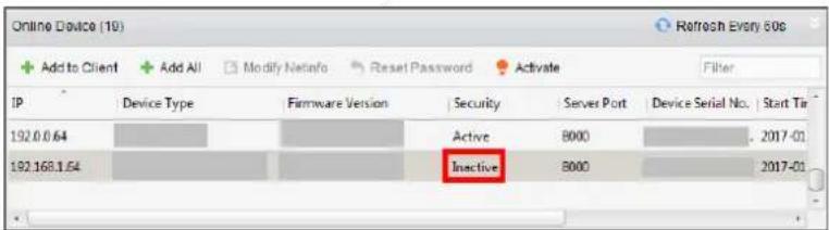
- Click the Acvate buon to pop up the Acvation interface.
- In the pop-up window, create a password in the password eld, and conrm the password.

STRONG PASSWORD RECOMMENDED— We highly recommend you create a strong password of your own choosing (using a minimum of 8 characters, including upper case leers, lower case leers, numbers, and special characters) in order to increase the security of your product. And we recommend you reset your password regularly, especially in the high security system, reseng the password monthly or weekly can beer protect your product.
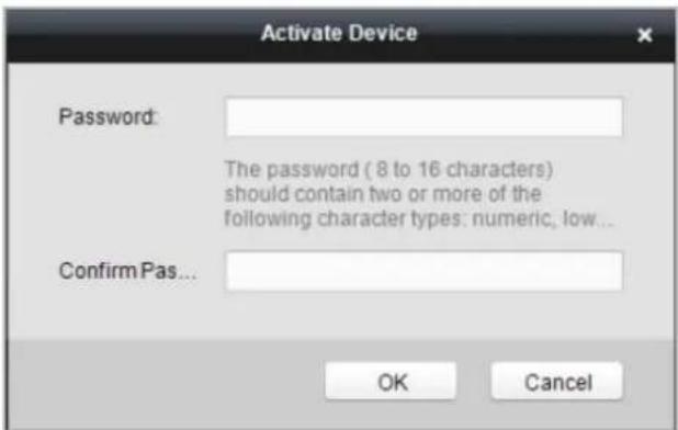
- Click OK buon to start acvaon.
- Click the Modify Nenfor buon to pop up the Network Parameter Modicaon interface.
- Change the device IP address to the same network segment with your computer by either modifying the IP address manually.
- Input the password and click the OK buon to save the sengs.
Chapter 7 Client Operation
You can set and operate the access control devices via the client software. This chapter will introduce the access control device related operaons in the client soware. For integrated operaons, refer to User Manual of iVMS-4200 Client Soware.
7.1 Function Module
Control Panel of iVMS-4200:
7.2 User Registration and Login
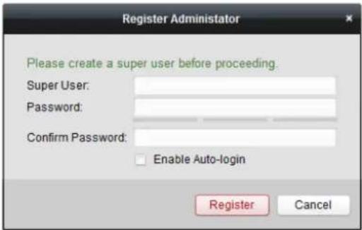
For the rst me to use iVMS-4200 client soware, you need to register a super user for login.
Steps:
- Input the super user name and password. The soware will judge password strength automacally, and we highly recommend you to use a strong password to ensure your data security.
- Conrm the password.
- Oponally, check the checkbox Enable Auto-login to log into the software automacally.
- Click Register. Then, you can log into the soware as the super user.

◆ A user name cannot contain any of the following characters: / \ : * ? " < > |. And the length of the password cannot be less than 6 characters.
For your privacy, we strongly recommend changing the password to something of your own choosing (using a minimum of 8 characters, including upper case leers, lower case leers, numbers, and special characters) in order to increase the security of your product.
◆ Proper conguraon of all passwords and other security sengs is the responsibility of the installer and/or end-user.
When opening iVMS-4200 aer registraon, you can log into the client soware with the registered user name and password.
Steps:
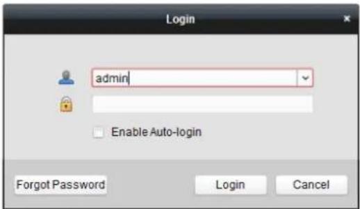
- Input the user name and password you registered.
Note: If you forget your password, please click Forgot Password and remember the encrypted string in the pop-up window. Contact your dealer and send the encrypted string to him to reset your password.
-
Oponally, check the checkbox Enable Auto-login to log into the software automacally.
-
Click Login.
Aer running the client soware, you can open the wizards (including video wizard, video wall wizard, security control panel wizard, access control and video intercom wizard, and aendance wizard), to guide you to add the device and do other setngs and operaons. For detailed conguraon about the wizards, please refer to the Quick Start Guide of iVMS-4200.
7.3 System Configuration
Purpose:
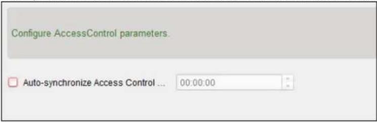
You can synchronize the missed access control events to the client.
Steps:
-
Click Tool – System Conguraon.
-
In the System Conguraon window, check the Auto-synchronize Access Control Event checkbox.
-
Set the synchronizaon me.
The client will auto-synchronize the missed access control event to the client at the set me.
7.4 Access Control Management
Purpose:
The Access Control module is applicable to access control devices and video intercom. It provides multiple funconalies, including person and card management, permission conguraon, access control status management, video intercom, and other advanced funcons.
You can also set the event conguraon for access control and display access control points and zones on E-map.
Note: For the user with access control module permissions, the user can enter the Access Control module and congregate the access control sengs.
Click in the control panel, and check Access Control to add the Access Control module to the control panel.
Click to enter the Access Control module.
Before you start:
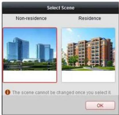
For the rst me opening the Access Control module, the following dialog will pop up and you are required to select the scene according to the actual needs.
You can select the scene as Non-residence and Residence.
Notes:
- Once the scene is congured, you cannot change it later.
- When you select Non-Residence mode, you cannot congregate the Aendance Rule when adding person.
The Access Control module is composed of the following sub modules.
 | Person and Card | Managing the organizaons, persons, and assigning cards to persons. |
 | Schedule and Template | Conguring the week schedule, holiday group, and seng the template. |
 | Permission | Assigning access control permissions to persons and applying to the devices. |
 | Advanced Funcon | Providing advanced funcons including access control parameters sengs, card reader authencaon, opening door with rst card, an-passing back, mul-door interlocking, and authencaon password. |
 | Video Intercom | Video intercom between client and resident, searching the dial log, and releasing noce. |
 | Search | Searching history events of access control; Searching call logs, unlocking logs, and released noces. |
 | Device Management | Managing the access control devices and video intercom devices. |
Note: In this chapter, we only introduce the operaons about access control.
7.4.1 Adding Access Control Device
Click 📋 in the Access Control module to enter the following interface.
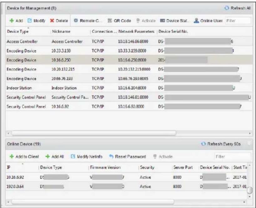
Note: Aer adding the device, you should check the device arming status in Tool – Device Arming Control. If the device is not armed, you should arm it, or you will not receive the events via the client soware. For details about device arming control, refer 7.12 Arming Control.
Creang Password
Purpose:
For some devices, you are required to create the password to acvate them before they can be added to the sware and work properly.
Note: This funcon should be supported by the device.
Steps:
- Enter the Device Management page.
- On the Device for Management or Online Device area, check the device status (shown on Security column) and select an inactive device.
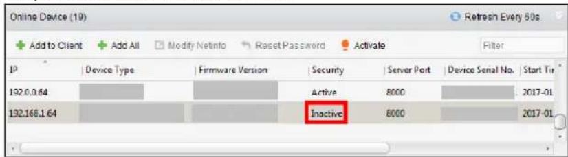
- Click the Acvate buon to pop up the Acvation interface.
- Create a password in the password eld, and conrm the password.

STRONG PASSWORD RECOMMENDED— We highly recommend you create a strong password of your own choosing (using a minimum of 8 characters, including upper case leers, lower case leers, numbers, and special characters) in order to increase the security of your product. And we recommend you reset your password regularly, especially in the high security system,
reseng the password monthly or weekly can beer protect your product.
![Activate User Name: admin Password: Valid password range [0-16]. You can use a combination of numbers, lowercase, uppercase and special character for your password with at least two kinds of them contained. Confirm Password: Enable Hik-Connect OK Cancel](/content/2026/05/812028/images/bf80dfae424894c097b5918b5372f3cdf7a17f2ad1b0c60480951634b58d3e62.jpg)
- (Oponal) Enable Hik-Connect service when acvang the device if the device supports.
1) Check Enable Hik-Connect checkbox to pop up the Note dialog.
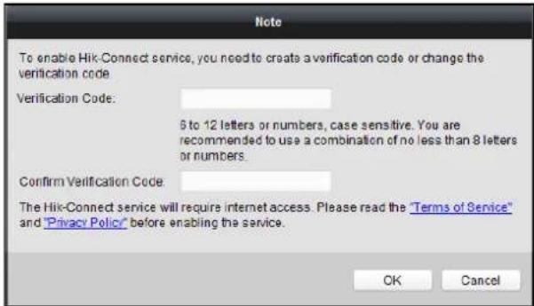
2) Create a vericaon code.
3) Conrm the vericaon code.
4) Click Terms of Service and Privacy Policy to read the requirements.
5) Click OK to enable the Hik-Connect service.
- Click OK to acvate the device.
A "The device is acvated." window pops up when the password is set successfully.
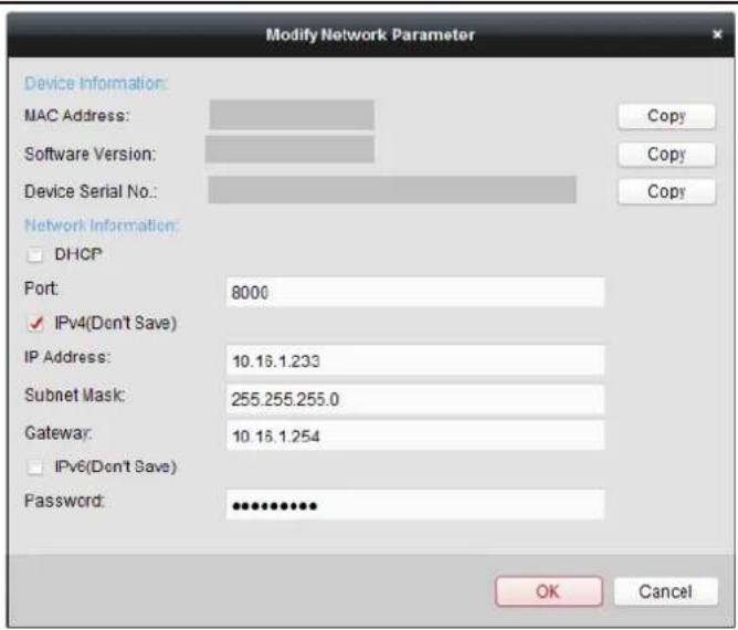
- Click Modify Nenfo to pop up the Modify Network Parameter interface.
Note: This funcon is only available on the Online Device area. You can change the device IP address to the same subnet with your computer if you need to add the device to the soware.
-
Change the device IP address to the same subnet with your computer by either modifying the IP address manually or checking the checkbox of DHCP.
-
Input the password set in step 4 and click OK to complete the network settings.
Adding Online Device
Purpose:
The acve online devices in the same local subnet with the client soware will be displayed on the Online Device area. You can click the Refresh Every 60s buon to refresh the informaon of the online devices.
Note: You can click & to hide the Online Device area.
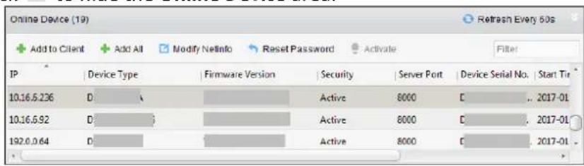
Steps:
- Select the devices to be added from the list.
Note: For the inacve device, you need to create the password for it before you can add the device properly. For detailed steps, please refer to Chapter 6 Acvating the Access Control Terminal.
-
Click Add to Client to open the device adding dialog box.
-
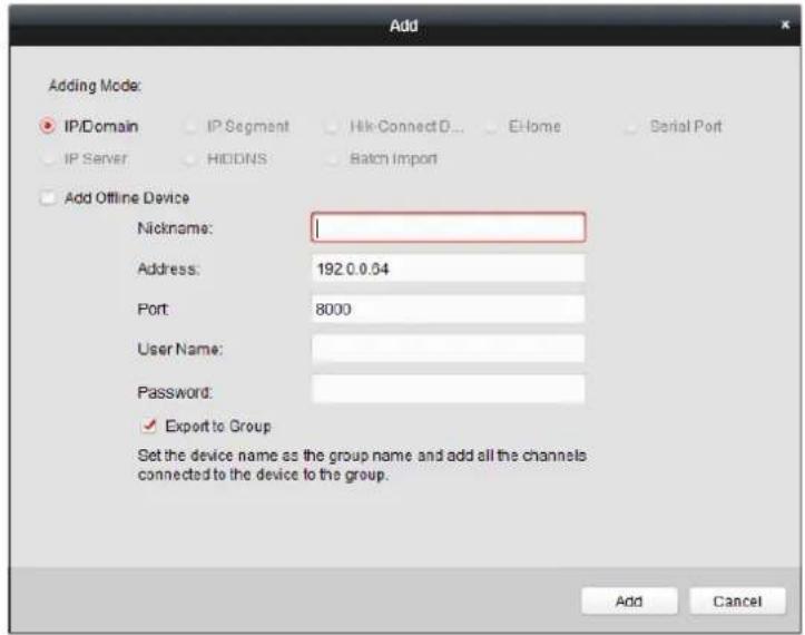
Input the required informaon.
Nickname: Edit a name for the device as you want.
Address: Input the device's IP address. The IP address of the device is obtained automatically in this adding mode.
Port: Input the device port No. The default value is 8000.
User Name: Input the device user name. By default, the user name is admin.
Password: Input the device password.

The password strength of the device can be checked by the soware. For your privacy, we strongly recommend changing the password to something of your own choosing (using a
minimum of 8 characters, including upper case leers, lower case leers, numbers, and special characters) in order to increase the security of your product. And we recommend you reset your password regularly, especially in the high security system, reseng the password monthly or weekly can beer protect your product.
- Oponally, check the Export to Group checkbox to create a group by the device name.
You can import all the channels of the device to the corresponding group by default.
Note: iVMS-4200 also provides a method to add the oine devices.
1) Check the Add Oine Device checkbox.
2) Input the required informaon, including the device channel number and alarm input number.
3) Click Add.
When the oine device comes online, the soware will connect it automacally.
- Click Add to add the device.
Adding Mulple Online Device
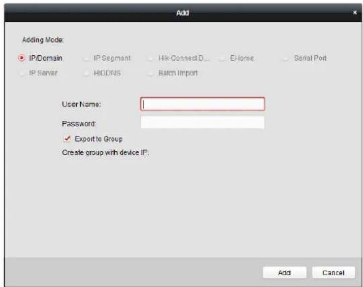
If you want to add mulple online devices to the client soware, click and hold Ctrl key to select mulple devices, and click Add to Client to open the device adding dialog box. In the pop-up message box, enter the user name and password for the devices to be added.
Adding All Online Devices
If you want to add all the online devices to the client soware, click Add All and click OK in the pop-up message box. Then enter the user name and password for the devices to be added.
Adding Devices by IP or Domain Name
Steps:
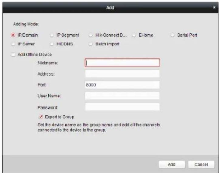
- Click Add to open the device adding dialog box.
- Select IP/Domain as the adding mode.
- Input the required informaon.
Nickname: Edit a name for the device as you want.
Address: Input the device's IP address or domain name.
Port: Input the device port No.. The default value is 8000.
User Name: Input the device user name. By default, the user name is admin.
Password: Input the device password.

The password strength of the device can be checked by the soware. For your privacy, we strongly recommend changing the password to something of your own choosing (using a minimum of 8 characters, including upper case leers, lower case leers, numbers, and special characters) in order to increase the security of your product. And we recommend you reset your password regularly, especially in the high security system, reseng the password monthly or weekly can beer protect your product.
- Oponally, check the Export to Group checkbox to create a group by the device name.
You can import all the channels of the device to the corresponding group by default.
Note: iVMS-4200 also provides a method to add the oine devices.
1) Check the Add Oine Device checkbox.
2) Input the required informaon, including the device channel number and alarm input number.
3) Click Add.
When the oine device comes online, the soware will connect it automacally.
- Click Add to add the device.
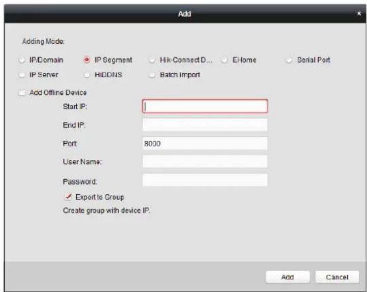
Adding Devices by IP Segment
Steps:
- Click Add to open the device adding dialog box.
- Select IP Segment as the adding mode.
- Input the required informaon.
Start IP: Input a start IP address.
End IP: Input an end IP address in the same network segment with the start IP.
Port: Input the device port No.. The default value is 8000.
User Name: Input the device user name. By default, the user name is admin.
Password: Input the device password.

The password strength of the device can be checked by the soware. For your privacy, we strongly recommend changing the password to something of your own choosing (using a minimum of 8 characters, including upper case leers, lower case leers, numbers, and special characters) in order to increase the security of your product. And we recommend you reset your password regularly, especially in the high security system, reseng the password monthly or weekly can beer protect your product.
- Oponally, check the Export to Group checkbox to create a group by the device name.
You can import all the channels of the device to the corresponding group by default.
Note: iVMS-4200 also provides a method to add the oine devices.
1) Check the Add Oine Device checkbox.
2) Input the required informaon, including the device channel number and alarm input number.
3) Click Add.
When the oine device comes online, the soware will connect it automacally.
- Click Add.
You can add the device which the IP address is between the start IP and end IP to the device
list.
Imporng Devices in Batch
Purpose:
The devices can be added to the soware in batch by inpung the device informaon in the pre-dened CSV le.
Steps:
- Click Add to open the device adding dialog box.
- Select Batch Import as the adding mode.
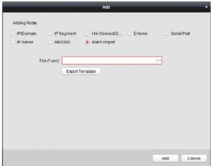
- Click Export Template and save the pre-dened template (CSV le) on your PC.
- Open the exported template le and input the required informaon of the devices to be added on the corresponding column.
Nickname: Edit a name for the device as you want.
Adding Mode: You can input 0, 2, 3, 4, 5, or 6 which indicated dierent adding modes. 0 indicates that the device is added by IP address or domain name; 2 indicates that the device is
added via IP server; 3 indicates that the device is added via HiDDNS; 4 indicates that the device is added via EHome protocol; 5 indicates that the device is added by serial port; 6 indicates that the device is added via Hik-Connect Domain.
Address: Edit the address of the device. If you set 0 as the adding mode, you should input the IP address or domain name of the device; if you set 2 as the adding mode, you should input the IP address of the PC that installs the IP Server; if you set 3 as the adding mode, you should input www.hik-online.com.
Port: Input the device port No.. The default value is 8000.
Device Informaon: If you set 0 as the adding mode, this eld is not required; if you set 2 as the adding mode, input the device ID registered on the IP Server; if you set 3 as the adding mode, input the device domain name registered on HiDDNS server; if you set 4 as the adding mode, input the EHome account; if you set 6 as the adding mode, input the device serial No.
User Name: Input the device user name. By default, the user name is admin.
Password: Input the device password.

The password strength of the device can be checked by the soware. For your privacy, we strongly recommend changing the password to something of your own choosing (using a minimum of 8 characters, including upper case leers, lower case leers, numbers, and special characters) in order to increase the security of your product. And we recommend you reset your password regularly, especially in the high security system, reseng the password monthly or weekly can beer protect your product.
Add Oine Device: You can input 1 to enable adding the oine device, and then the soware will automatically connect it when the oine device comes online. 0 indicates disabling this funcon.
Export to Group: You can input 1 to create a group by the device name (nickname). All the channels of the device will be imported to the corresponding group by default. 0 indicates disabling this funcon.
Channel Number: If you set 1 for Add Oine Device, input the channel number of the device. If you set 0 for Add Oine Device, this eld is not required.
Alarm Input Number: If you set 1 for Add Oine Device, input the alarm input number of the device. If you set 0 for Add Oine Device, this eld is not required.
Serial Port No.: If you set 5 as the adding mode, input the serial port No. for the access control device.
Baud Rate: If you set 5 as the adding mode, input the baud rate of the access control device.
DIP: If you set 5 as the adding mode, input the DIP address of the access control device.
Hik-Connect Account: If you set 6 as the adding mode, input the Hik-Connect account.
Hik-Connect Password: If you set 6 as the adding mode, input the Hik-Connect password.
-
Click and select the template le.
-
Click Add to import the devices.
The devices will be displayed on the device list for management aer added successfully. You can check the resource usage, HDD status, recording status, and other informaon of the added devices on the list.
Click Refresh All to refresh the informaon of all added devices. You can also input the device name in the Iter eld for search.
7.4.2 Viewing Device Status
In the device list, you can select the device and then click Device Status buon to view its status.
Note: The interface may dierent from the picture displayed above. Refer to the actual interface when adopng this funcon.
Door Status: The status of the connected door.
Host Status: The status of the host, including Storage Baery Power Voltage, Device Power Supply Status, Mul-door Interlocking Status, An-passing Back Status, and Host An-Tamper Status.
Card Reader Status: The status of card reader.
Note: If you use the card reader with RS-485 conncon, you can view the status of online or oine. If you use the card reader with Wiegand conncon, you can view the status of oine.
Alarm Output Status: The alarm output status of each port.
Event Sensor Status: The event sensor status of each port.
Arming Status: The status of the device.
7.4.3 Eding Basic Informaon
Purpose:
Aer adding the access control device, you can edit the device basic informaon.
Steps:
- Select the device in the device list.
- Click Modify to pop up the modifying device informaon window.
- Click Basic Informaon tab to enter the Basic Informaon interface.
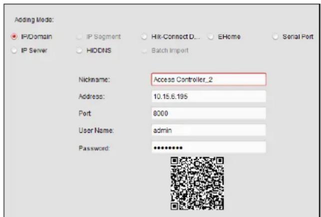
- Edit the device informaon, including the adding mode, the device name, the device IP address, port No., user name, and the password.
7.4.4 Remote Conguraon
Purpose:
In the device list, select the device and click Remote Conguraon button to enter the remote conguraon interface. You can set the detailed parameters of the selected device.
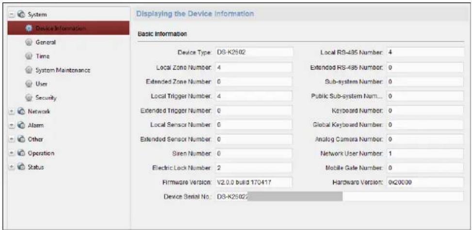
Checking Device Informaon
Steps:
- In the device list, you can click Remote Conguraon to enter the remote conguraon interface.
- Click System -> Device Informaon to check the device basic informaon and the device version informaon.
Eding Device Name
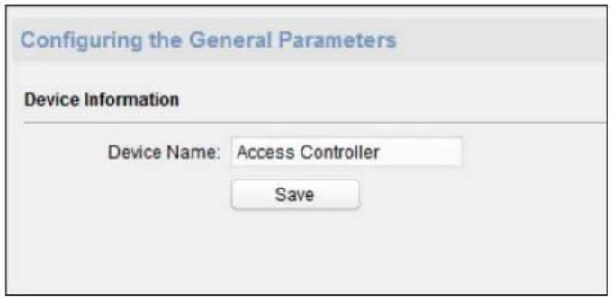
In the Remote Conguraon interface, click System -> General to congregate the device name. Click Save to save the sengs.
Eding Time
Steps:
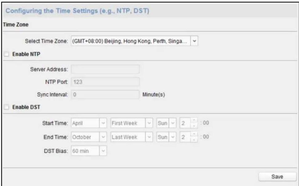
- In the Remote Conguraon interface, click System -> Time to conjure the me zone.
- (Oponal) Check Enable NTP and congregate the NTP server address (or server domain), the NTP port, and the synchronizaon interval.
- (Oponal) Check Enable DST and congregate the DST star me, end me and the bias.
- Click Save to save the sengs.
Seng System Maintenance
Steps:
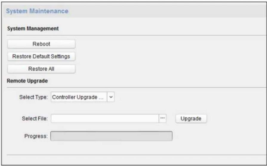
- In the Remote Conguraon interface, click System -> System Maintenance.
- Click Reboot to reboot the device.
Or click Restore Default Sengs to restore the device settings to the default ones, excluding the IP address.
Or click Restore All to restore the device parameters to the default ones. The device should be acvated aer restoring.
Note: The conguraon le contains the device parameters.
- You can also remote upgrade the device.
1) In the Remote Upgrade part, select an upgrade le type in the dropdown list.
You can select Controller Upgrade File or Card Reader Upgrade in the drop-down list.
2) Click to select the upgrade le.
3) Click Upgrade to start upgrading.
Note: Only card readers connected via RS-485 can be upgraded. DS-K2800 series access controller only supports Wiegand card reader.
Managing User
Steps:
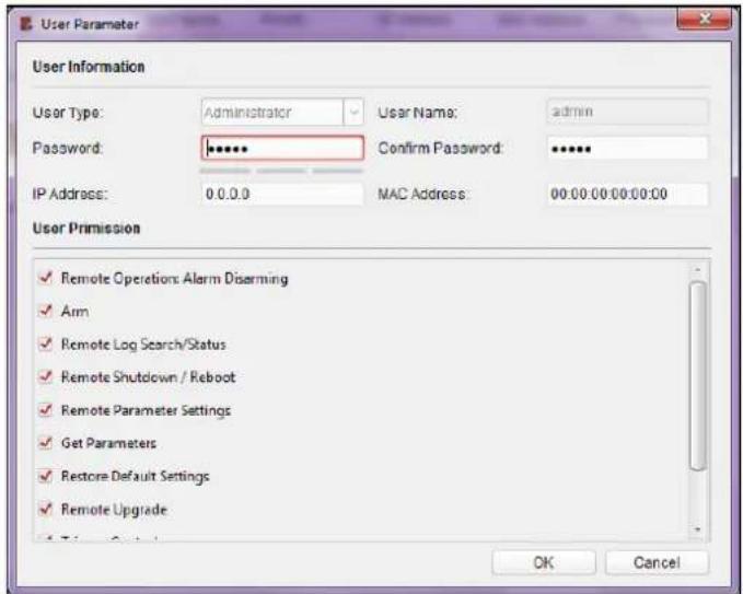
- In the Remote Conguraon interface, click System -> User.
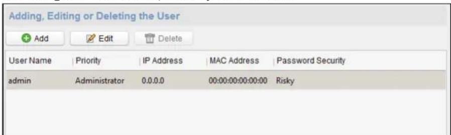
- Click Add to add the user.
Or select a user in the user list and click Edit to edit the user. You are able to edit the user password, the IP address, the MAC address and the user permission. Click OK to conrm eding.
Seng Security
Steps:
1. Click System -> Security.
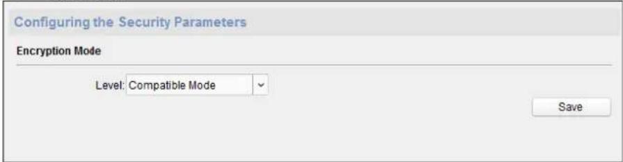
- Select the encrypon mode in the dropdown list.
You can select Compatible Mode or Encrypon Mode. - Click Save to save the sengs.
Conguring Network Parameters
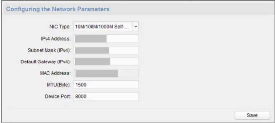
Click Network -> General. You can congregate the NIC type, the IPv4 address, the subnet mask (IPv4), the default gateway (IPv4), MTU address, MTU, and the device port. Click Save to save the sengs.
Conguring Advanced Network
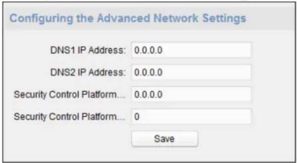
Click Network -> Advanced Sengs. You can congregate the DNS address 1, the DNS address 2, the alarm host IP and the alarm host port. Click Save to save the sengs.
Conguring Relay Parameters
Steps:
- Click Alarm -> Relay.
You can view the relay parameters.
| Configuring Relay Parameters | ||||
| Relay | Name | Output Delay(s) | Zone Linkage | Settings |
| 1 | 0 | None | ✓ | |
| 2 | 0 | None | ✓ | |
| 3 | 0 | None | ✓ | |
| 4 | 0 | None | ✓ | |
- Click the 📋 to pop up the Relay Parameters Sengs window.
- Set the relay name and the output delay.
- Click Save to save the parameters.
Or click Copy to... to copy the relay informaon to other relays.
Conguring Access Control Parameters
Steps:
- In the Remote Conguraon interface, click Other -> Access Control Parameters.
- Select and check the Press Key to Input Card No. checkbox.
- Click Save to save the sengs.
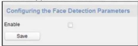
Conguring Face Detecon Parameters
Click Other -> Face Detecon. You can check the Enable checkbox to enable the device face detecon funcon.
Note: Only devices with video funcon support this funcon.
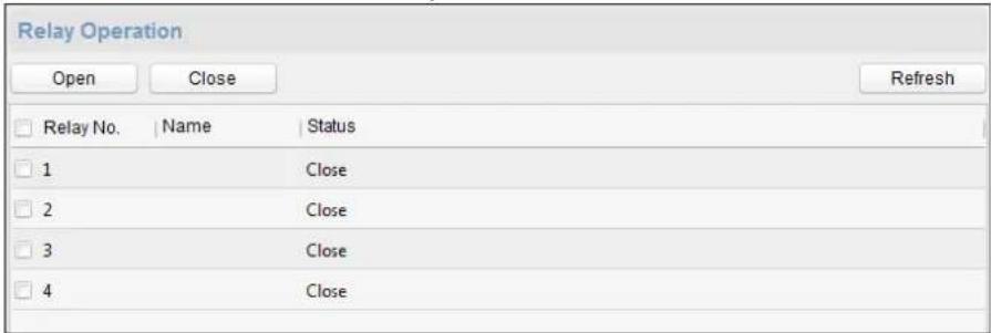
Operang Relay
Steps:
- Click Operaon -> Relay.
You can view the relay status.
- Check the relay checkbox
- Click Open or Close to open/close the relay.
- (Oponal) Click Refresh to refresh the relay status.
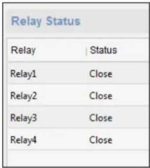
Viewing Relay Status
Click Status -> Relay to view the relay status.
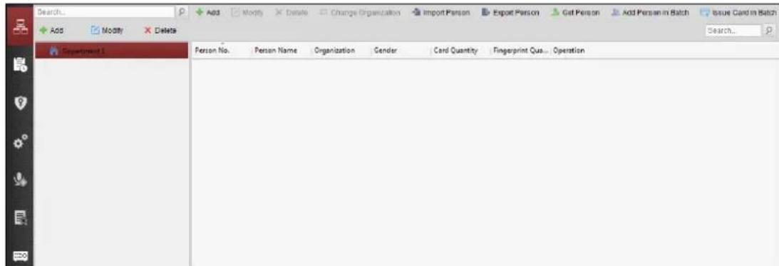
7.5 Person and Card Management
You can add, edit, and delete the organization and person in Person and Card Management module.
Click to enter the Person and Card Management interface.
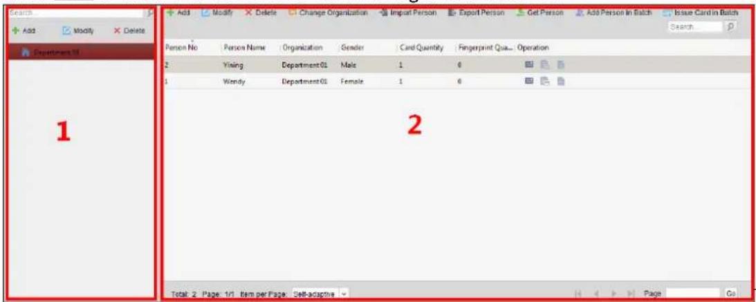
The interface
is divided into two parts: Organizaon Management and Person Management.
| 1 | Organizaon Management | You can add, edit, or delete the organizaon as desired. |
| 2 | Person Management | Aer adding the organizaon, you can add the person to the organizaon and issue card to persons for further management. |
7.5.1 Organizaon Management
Adding Organizaon
Steps:
- In the organizaon list on the le, you should add a top organizaon as the parent organizaon of all organizaons.
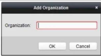
Click Add buon to pop up the adding organizaon interface.
-
Input the Organizaon Name as desired.
-
Click OK to save the adding.
-
You can add mulple levels of organizaons according to the actual needs.
To add sub organizations, select the parent organizaon and click Add.
Repeat Step 2 and 3 to add the sub organizaon.
Then the added organizaon will be the sub-organizaon of the upper-level organizaon.
Note: Up to 10 levels of organizaons can be created.
Modifying and Deleng Organizaon
You can select the added organizaon and click Modify to modify its name.
You can select an organizaon, and click Delete buon to delete it.
Notes:
● The lower-level organizaons will be deleted as well if you delete an organizaon.
● Make sure there is no person added under the organizaon, or the organizaon cannot be deleted.
7.5.2 Person Management
Aer adding the organizaon, you can add person to the organizaon and manage the added person such as issuing cards in batch, imporng and exporng persons informaon in batch, etc.
Note: Up to 10,000 persons or cards can be added.
Adding Person
Adding Person (Basic Informaon)
Steps:
- Select an organizaon in the organizaon list and click Add buon on the Person panel to pop up the adding person dialog.
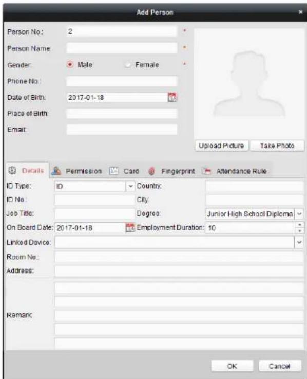
- The Person No. will be generated automacally and is not editable.
- Input the basic information including person name, gender, phone No., birthday details, and email address.
- Click Upload Picture to select the person picture from the local PC to upload it to the client. Note: The picture should be in *.jpg format.
- (Oponal) You can also click Take Phone to take the person's photo with the PC camera.
- Click OK to nish adding.
Adding Person (Detailed Informaon)
Steps:
- In the Add Person interface, click Details tab.
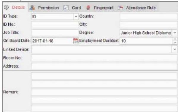
- Input the detailed informaon of the person, including person's ID type, ID No., country, etc., according to actual needs.
- Linked Device: You can bind the indoor staon to the person.
Note: If you select Analog Indoor Staon in the Linked Device, the Door Staon eld will display and you are required to select the door staon to communicate with the analog
indoor staon.
● Room No.: You can input the room No. of the person.
3. Click OK to save the sengs.
Adding Person (Permission)
You can assign the permissions (including operaon permissions of access control device and access control permissions) to the person when adding person.
Note: For seeing the access control permission, refer to Chapter 7.7 Permission Conguraon.
Steps:
- In the Add Person interface, click Permission tab.
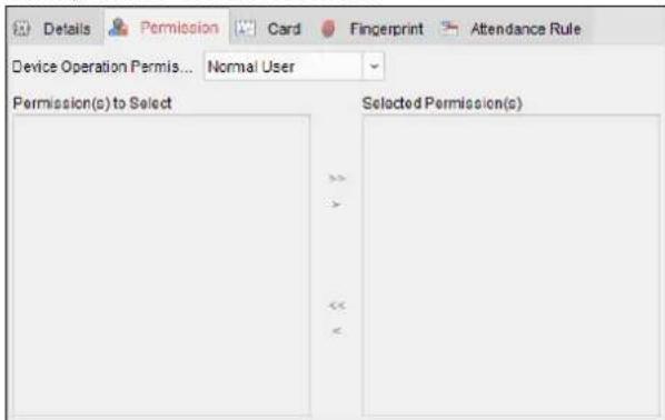
- In the Device Operaon Role field, select the role of operang the access control device.
Normal User: The person has the permission to check-in/out on the device, pass the access control point, etc.
Administrator: The person has the normal user permission, as well as permission to congregate the device, including adding normal user, etc.
- In the Permission(s) to Select list, all the configured permissions display.
Check the permission(s) checkbox(es) and click > to add to the Selected Permission(s) list.
(Oponal) You can click >> to add all the displayed permissions to the Selected Permission(s) list.
(Oponal) In the Selected Permission(s) list, select the selected permission and click < to remove it. You can also click << to remove all the selected permissions.
4. Click OK to save the sengs.
Adding Person (Card)
You can add card and issue the card to the person.
Steps:
- In the Add Person interface, click Card tab.
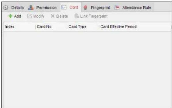
- Click Add to pop up the Add Card dialog.
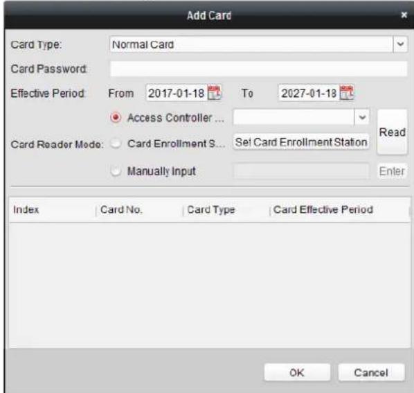
-
Select the card type according to actual needs.
-
Normal Card
- Card for Disabled Person: The door will remain open for the congured me period for the card holder.
- Card in Blacklist: The card swiping acon will be uploaded and the door cannot be opened.
● Patrol Card: The card swiping acon can used for checking the working status of the inspecon sta. The access permission of the inspecon sta is congorable. - Duress Card: The door can open by swiping the duress card when there is duress. At the same me, the client can report the duress event.
● Super Card: The card is valid for all the doors of the controller during the congured schedule. - Visitor Card: The card is assigned for visitors. For the Visitor Card, you can set the Max. Swipe Times.
Notes:
● The Max. Swipe Times should be between 0 and 255. When your swiping card mes is more than the congured mes, card swiping will be invalid.
- When set the mes as 0, it means the card swiping is unlimited.
- Input the password of the card itself in the Card Password eld. The card password should contain 4 to 8 digits.
Note: The password will be required when the card holder swiping the card to get enter to or exit from the door if you enable the card reader authencaon mode as Card and Password, Password and Fingerprint, and Card, Password, and Fingerprint. For details, Chapter 7.8.2 Card Reader Authencaon.
-
Click to set the eective me and expiry me of the card.
-
Select the Card Reader Mode for reading the card No.
- Access Controller Reader: Place the card on the reader of the Access Controller and click Read to get the card No.
- Card Enrollment Staon: Place the card on the Card Enrollment Staon and click Read to get the card No.
Note: The Card Enrollment Staon should connect with the PC running the client. You can click Set Card Enrollment Staon to enter the following dialog.
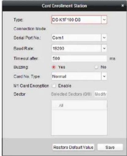
2) Select the Card Enrollment Staon type.
Note: Currently, the supported card reader types include DS-K1F100-D8, DS-K1F100-M, DS-K1F100-D8E, and DS-K1F180-D8E.
3) Set the serial port No., the baud rate, the meout value, the buzzing, or the card No. type.
Note: DS-K2800 series access controller does not support the M1 card encrypon funcon.
4) Click Save buon to save the sengs.
You can click Restore Default Value buon to restore the defaults.
● Manually Input: Input the card No. and click Enter to input the card No.
- Click OK and the card(s) will be issued to the person.
- (Oponal) You can select the added card and click Edit or Delete to edit or delete the card.
- Click OK to save the sengs.
Adding Person (Aendance Rule)
You can set the aendance rule for the person.
Note: This tab page will display when you select Non-Residence mode in the applicaon scene when running the soware for the rst me.
Steps:
- In the Add Person interface, click Aendance Rule tab.
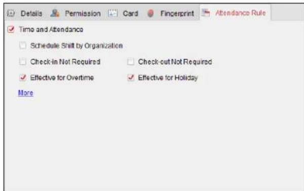
- If the person joins in the me and aendance, check the Time and Aendance checkbox to enable this funcon for the person. Then the person's card swiping records will be recorded and analyzed for me and aendance.
For details about Time and Aendance, click More to go to the Time and Aendance module.
- Click OK to save the sengs.
Imporng and Exporng Person Informaon
The person informaon can be imported and exported in batch.
Steps:
- Exporng Person: You can export the added persons' information in Excel format to the local PC.
1) Aer adding the person, you can click Export Person button in the Person and Card tab to pop up the following dialog.
2) Click ☐ to select the path of saving the exported Excel le.
3) Check the checkboxes to select the person informaon to export.
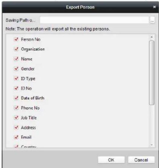
4) Click OK to start exporng.
- Imporng Person: You can import the Excel le with persons informaon in batch from the local PC
1) click Import Person buon in the Person and Card tab.
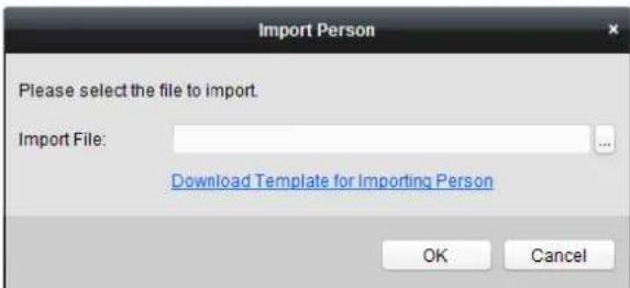
2) You can click Download Template for Imporng Person to download the template rst.
3) Input the person informaon to the downloaded template.
4) Click to select the Excel le with person informaon.
5) Click OK to start imporng.
Geng Person Informaon from Access Control Device
If the added access control device has been congured with person informaon (including person details, ngerprint, issued card informaon), you can get the person informaon from the device and import to the client for further operaon.
Note: This funcon is only supported by the device the conncon method of which is TCP/IP when adding the device.
Steps:
- In the organizaon list on the le, click to select an organizaon to import the persons.
- Click Get Person buon to pop up the following dialog box.
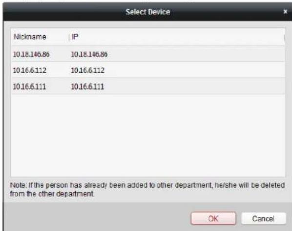
- The added access control device will be displayed.
- Click to select the device and then click OK to start getting the person informaon from the device.
You can also double click the device name to start geng the person informaon.
Notes:
- The person informaon, including person details, person's ngerprint informaon (if congured), and the linked card (if congured), will be imported to the selected organizaon.
- If the person name stored in the device is empty, the person name will be lled with the issued card No. aer imporng to the client.
● The gender of the persons will be Male by default.
● Up to 10000 persons with up to 5 cards each can be imported.
Managing Person
Modifying and Deleng Person
To modify the person informaon and aendance rule, click or in the Operaon column, or select the person and click Modify to open the eding person dialog.
You can click to view the person's card swiping records.
To delete the person, select a person and click Delete to delete it.
Note: If a card is issued to the current person, the linkage will be invalid after the person is deleted.
Changing Person to Other Organizaon
You can move the person to another organizaon if needed.
Steps:
- Select the person in the list and click Change Organizaon buon.
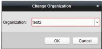
- Select the organizaon to move the person to.
- Click OK to save the sengs.
Issuing Card in Batch
You can issue mulple cards for the person with no card issued in batch.
Steps:
- Click Issue Card in Batch button to enter the following dialog.
All the added person with no card issued will display in the Person(s) with No Card Issued list.
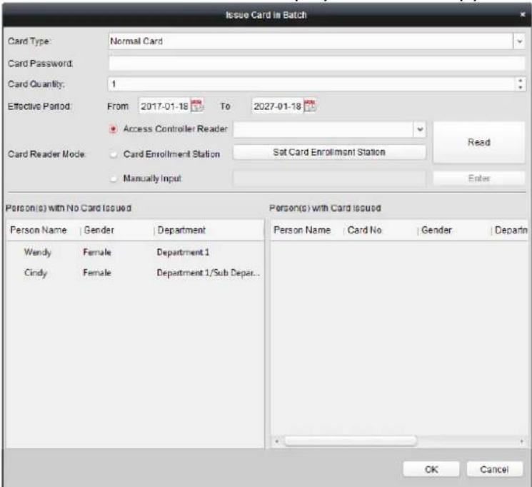
- Select the card type according to actual needs.
Note: For details about the card type, refer to Adding Person.
- Input the password of the card itself in the Card Password eld. The card password should contain 4 to 8 digits.
Note: The password will be required when the card holder swiping the card to get enter to or exit from the door if you enable the card reader authencaon mode as Card and Password, Password and Fingerprint, and Card, Password, and Fingerprint. For details, refer to Chapter 7.8.2 Card Reader Authencaon.
- Input the card quantity issued for each person.
For example, if the Card Quantity is 3, you can read or enter three card No. for each person.
-
Click 📋 to set the eective me and expiry me of the card.
-
Select the Card Reader Mode for reading the card No.
-
Access Controller Reader: Place the card on the reader of the Access Controller and click Read to get the card No.
- Card Enrollment Station: Place the card on the Card Enrollment Staon and click Read to get the card No.
Note: The Card Enrollment Staon should connect with the PC running the client. You can click Set Card Enrollment Staon to enter the following dialog.
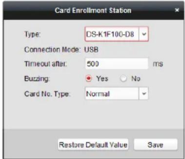
1) Select the Card Enrollment Staon type.
Note: Currently, the supported card reader types include DS-K1F100-D8, DS-K1F100-M, DS-K1F100-D8E, and DS-K1F180-D8E.
2) Set the parameters about the connected card enrollment staon.
3) Click Save buon to save the sengs.
You can click Restore Default Value buon to restore the defaults.
- Manually Input: Input the card No. and click Enter to input the card No.
- Aer issuing the card to the person, the person and card informaon will display in the Person(s) with Card Issued list.
- Click OK to save the sengs.
7.6 Schedule and Template
Purpose:
You can congregate the template including week schedule and holiday schedule. Aer seng the templates, you can adopt the congregate templates to access control permissions when seng the permission, so that the access control permission will take eect in the me duraons of the template.
Click

to enter the schedule and template interface.
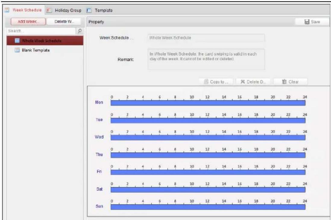
You can manage the schedule of access control permission including Week Schedule, Holiday Schedule, and Template. For permission sengs, please refer to Chapter 7.7 Permission Conguraon.
7.6.1 Week Schedule
Click Week Schedule tab to enter the Week Schedule Management interface.
The client denes two kinds of week plan by default: Whole Week Schedule and Blank Schedule, which cannot be deleted and edited.
● Whole Week Schedule: Card swiping is valid on each day of the week.
- Blank Schedule: Card swiping is invalid on each day of the week.
You can perform the following steps to dene custom schedules on your demand.
Steps:
- Click Add Week Schedule buon to pop up the adding schedule interface.
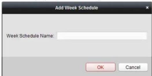
- Input the name of week schedule and click OK buon to add the week schedule.
- Select the added week schedule in the schedule list and you can view its property on the right.
You can edit the week schedule name and input the remark informaon. - On the week schedule, click and drag on a day to draw on the schedule, which means in that
period of me, the congured permission is acvated.
Note: Up to 8 me periods can be set for each day in the schedule.
- When the cursor turns to 📋, you can move the selected me bar you just edited. You can also edit the displayed me point to set the accurate me period.
When the cursor turns to , you can lengthen or shorten the selected me bar.
-
Oponally, you can select the schedule me bar, and then click Delete Duraon to delete the selected me bar, or click Clear to delete all the me bars, or click Copy to Week to copy the me bar sengs to the whole week.
-
Click Save to save the sengs.
7.6.2 Holiday Group
Click Holiday Group tab to enter the Holiday Group Management interface.
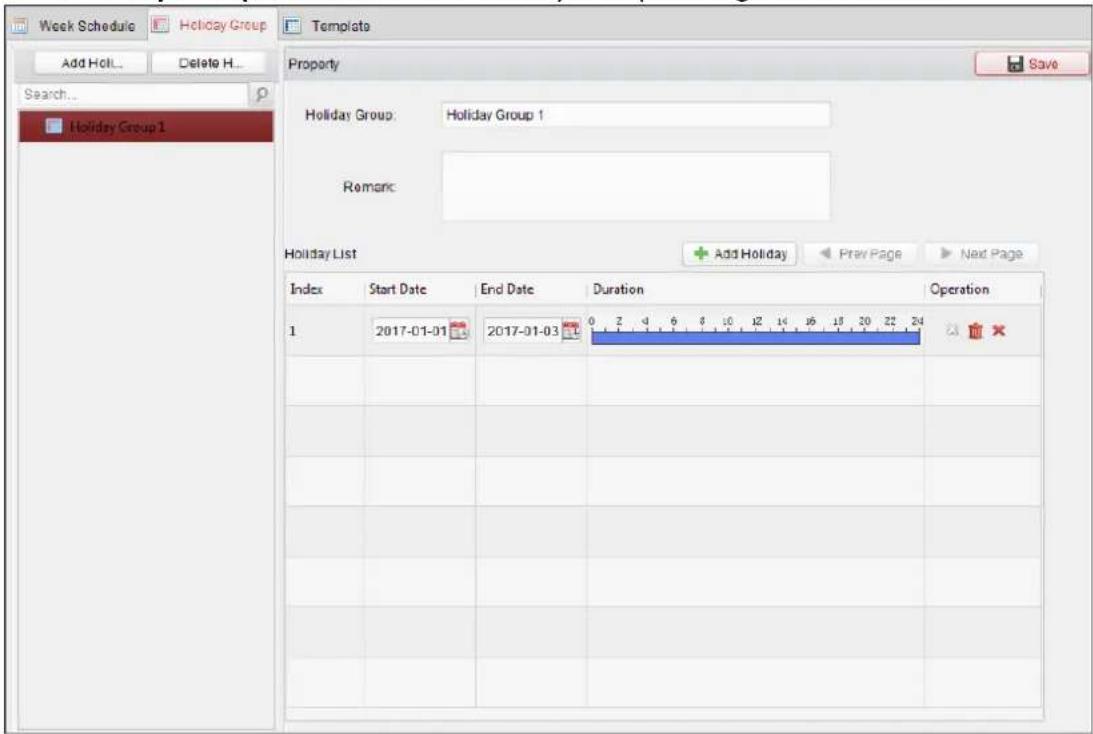
Steps:
- Click Add Holiday Group buon on the le to pop up the adding holiday group interface.
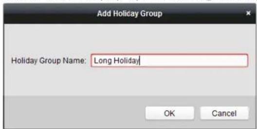
- Input the name of holiday group in the text led and click OK buon to add the holiday group.
- Select the added holiday group and you can edit the holiday group name and input the remark
informaon.
- Click Add Holiday icon on the right to add a holiday period to the holiday list and conjure the duraon of the holiday.
Note: Up to 16 holidays can be added to one holiday group.
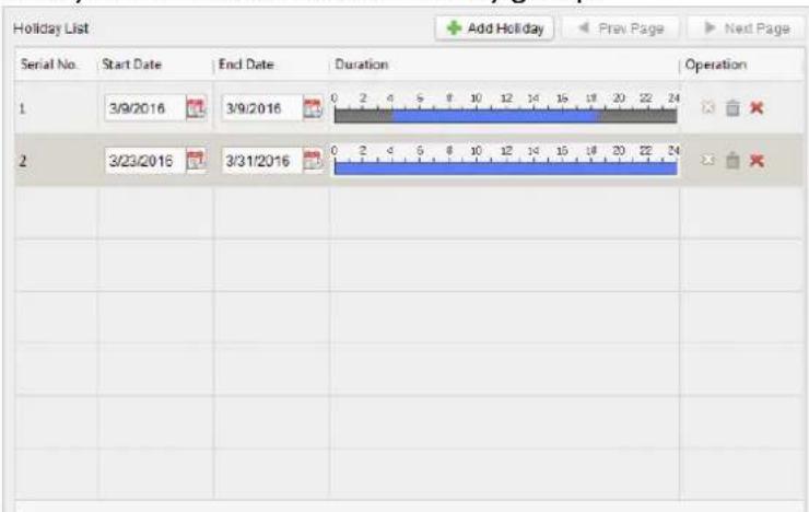
1) On the period schedule, click and drag to draw the period, which means in that period of me, the congured permission is acvated.
Note: Up to 8 me duraons can be set for each period in the schedule.
2) When the cursor turns to 📋, you can move the selected me bar you just edited. You can also edit the displayed me point to set the accurate me period.
3) When the cursor turns to , you can lengthen or shorten the selected me bar.
4) Oponally, you can select the schedule me bar, and then click to delete the selected me bar, or click to delete all the me bars of the holiday, or click to delete the holiday directly.
- Click Save to save the sengs.
Note: The holidays cannot be overlapped with each other.
7.6.3 Template
Aer seng the week schedule and holiday group, you can congregate the template which contains week schedule and holiday group schedule.
Note: The priority of holiday group schedule is higher than the week schedule.
Click Template tab to enter the Template Management interface.
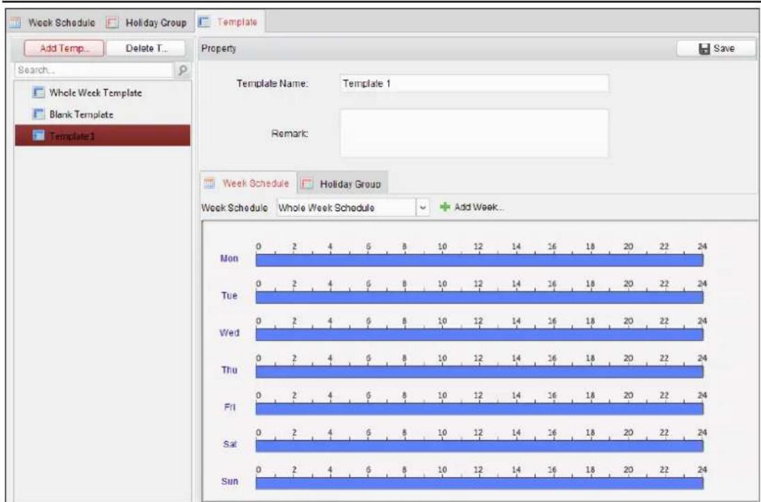
There are two pre-dened templates by default: Whole Week Template and Blank Template, which cannot be deleted and edited.
● Whole Week Template: The card swiping is valid on each day of the week and it has no holiday group schedule.
- Blank Template: The card swiping is invalid on each day of the week and it has no holiday group schedule.
You can dene custom templates on your demand.
Steps:
- Click Add Template to pop up the adding template interface.
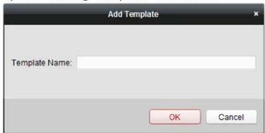
- Input the template name in the text led and click OK button to add the template.
- Select the added template and you can edit its property on the right. You can edit the template name and input the remark informaon.
- Select a week schedule to apply to the schedule.
Click Week Schedule tab and select a schedule in the dropdown list.
You can also click Add Week Schedule to add a new week schedule. For details, refer to Chapter 7.6.1 Week Schedule.
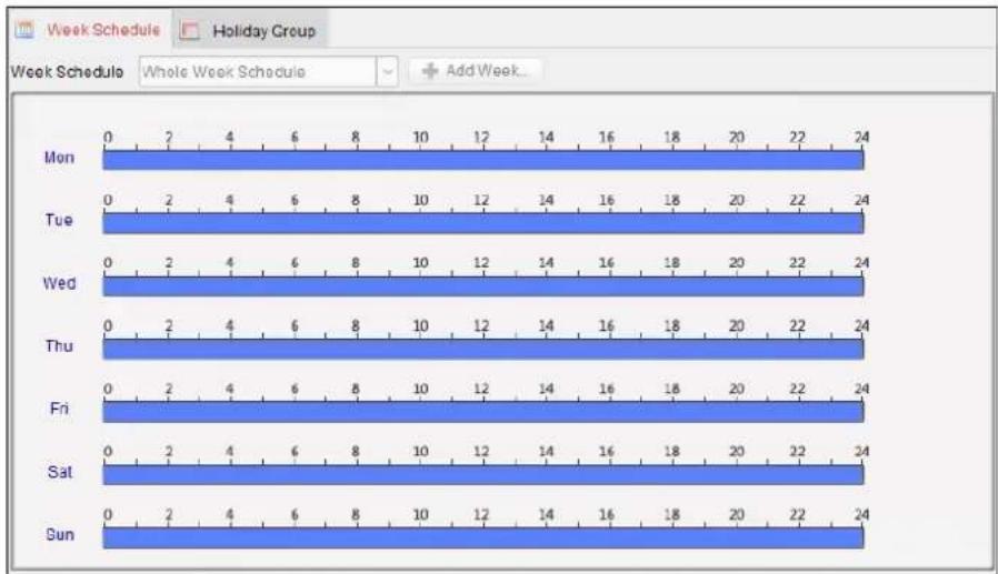
bar
| Day | Week Schedule 0 | Week Schedule 2 | Week Schedule 4 | Week Schedule 6 | Week Schedule 8 | Week Schedule 10 | Week Schedule 12 | Week Schedule 14 | Week Schedule 16 | Week Schedule 18 | Week Schedule 20 | Week Schedule 22 | Week Schedule 24 | |---|---|---|---|---|---|---|---|---|---|---|---|---|---| | Mon | 0 | 2 | 4 | 6 | 8 | 10 | 12 | 14 | 16 | 18 | 20 | 22 | 24 | | Tue | 0 | 2 | 4 | 6 | 8 | 10 | 12 | 14 | 16 | 18 | 20 | 22 | 24 | | Wed | 0 | 2 | 4 | 6 | 8 | 10 | 12 | 14 | 16 | 18 | 20 | 22 | 24 | | Thu | 0 | 2 | 4 | 6 | 8 | 10 | 12 | 14 | 16 | 18 | 20 | 22 | 24 | | Fri | 0 | 2 | 4 | 6 | 8 | 10 | 12 | 14 | 16 | 18 | 20 | 22 | 24 | | Sat | 0 | 2 | 4 | 6 | 8 | 10 | 12 | 14 | 16 | 18 | 20 | 22 | 24 | | Sun | 0 | 2 | 4 | 6 | 8 | 10 | 12 | 14 | 16 | 18 | 20 | 22 | 24 |- Select holiday groups to apply to the schedule.
Note: Up to 4 holiday groups can be added.
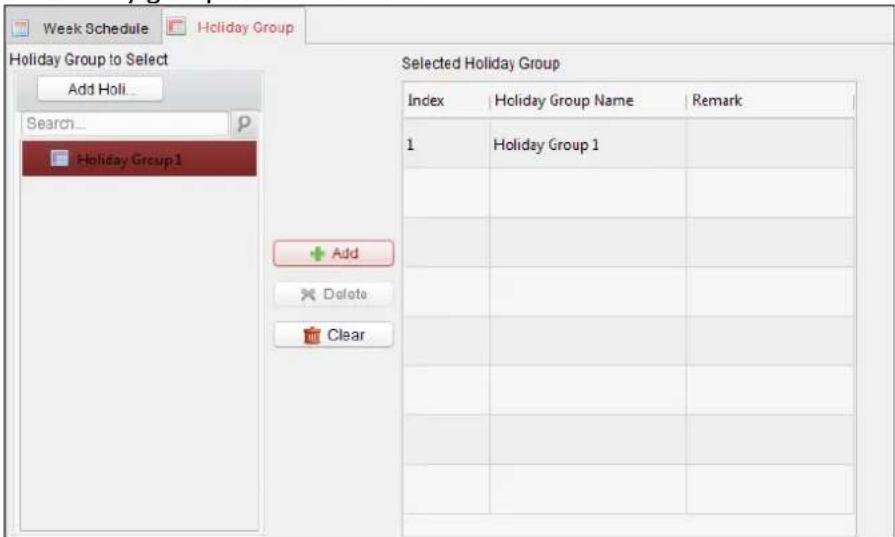
Click to select a holiday group in the list and click Add to add it to the template. You can also click Add Holiday Group to add a new one. For details, refer to Chapter 7.6.2 Holiday Group. You can click to select an added holiday group in the right-side list and click Delete to delete it. You can click Clear to delete all the added holiday groups.
- Click Save buon to save the sengs.
7.7 Permission Configuration
In Permission Conguraon module, you can add, edit, and delete the access control permission, and then apply the permission sengs to the device to take eect.
Click icon to enter the Access Control Permission interface.
7.7.1 Adding Permission
Purpose:
You can assign permission for persons to enter/exist the access control points (doors) in this secon.
Steps:
- Click Add icon to enter following interface.
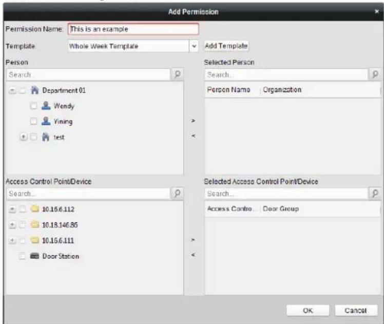
-
In the Permission Name eld, input the name for the permission as desired.
-
Click on the dropdown menu to select a template for the permission.
Note: You should congregate the template before permission sengs. You can click Add Template buon to add the template. Refer to Chapter 7.6 Schedule and Template for details.
- In the Person list, all the added persons display.
Check the checkbox(es) to select person(s) and click > to add to the Selected Person list. (Oponal) You can select the person in Selected Person list and click < to cancel the selecon.
- In the Access Control Point/Device list, all the added access control points (doors) and door staons will display.
Check the checkbox(es) to select door(s) or door staon(s) and click > to add to the selected list.
(Oponal) You can select the door or door staon in the selected list and click < to cancel the selecon.
- Click OK buon to complete the permission adding. The selected person will have the
permission to enter/exit the selected door/door staon with their linked card(s) or ingerprints.
- (Oponal) aer adding the permission, you can click Details to modify it. Or you can select the permission and click Modify to modify.
You can select the added permission in the list and click Delete to delete it.
7.7.2 Applying Permission
Purpose:
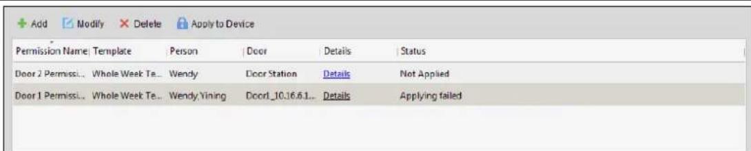
Aer conguring the permissions, you should apply the added permission to the access control device to take eect.
Steps:
- Select the permission(s) to apply to the access control device. To select multiple permissions, you can hold the Ctrl or Shi key and select permissions.
- Click Apply to Device to start applying the selected permission(s) to the access control device or door staon.
- The following window will pop up, indicang the applying permission result.

7.8 Advanced Functions
Purpose:
Aer conguring the person, template, and access control permission, you can congregate the advanced funcons of access control application.
Note: The advanced funcons should be supported by the device.
Click

n to enter the following interface.
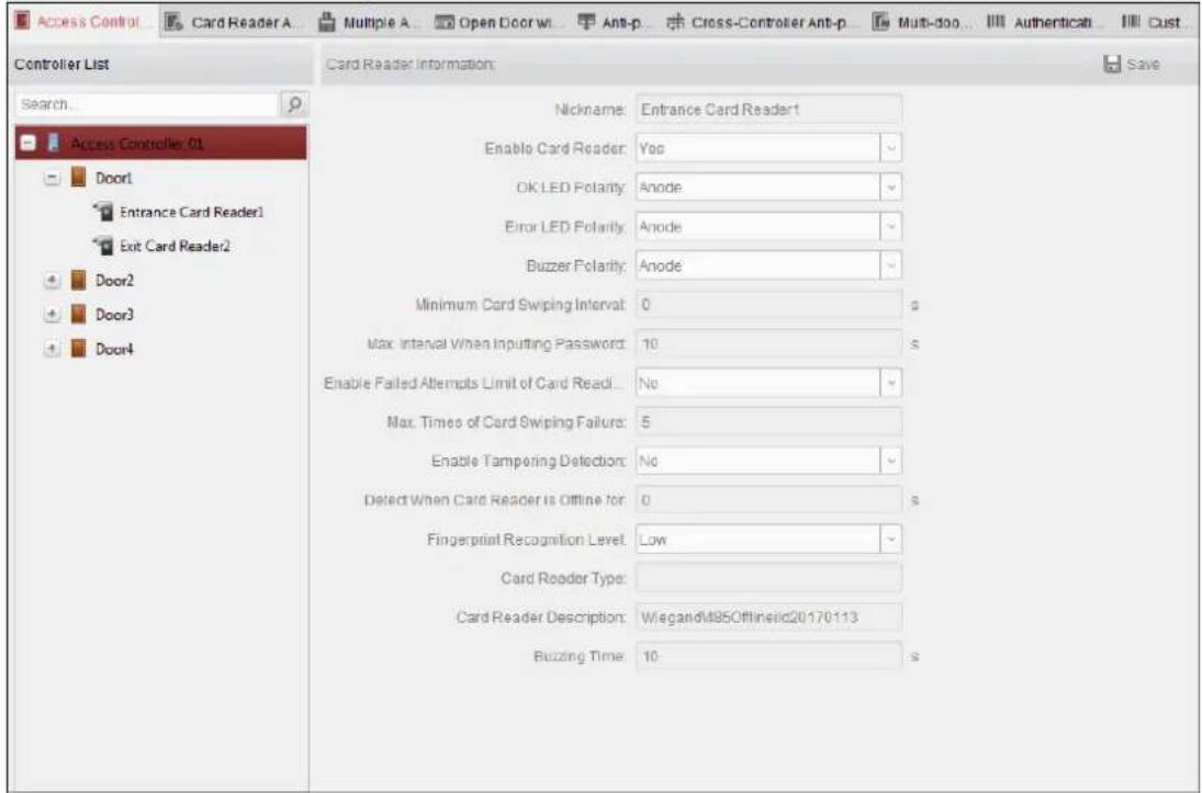
7.8.1 Access Control Parameters
Purpose:
Aer conguring the person, template, and access control permission, you can congregate the advanced funcons of access control applicaon.
Click Access Control Parameters tab to enter the parameters sengs interface.
Door Parameters
Steps:
- In the controller list on the le, click +to expand the access control device, select the door (access control point) and you can edit the informaon of the selected door on the right.
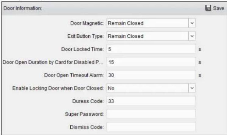
- You can eding the following parameters:
Door Magnec: The Door Magnec is in the status of Remain Closed (excluding special conditions).
Exit Buon Type: The Exit Buon Type is in the status of Remain Open (excluding special conditions).
Door Locked Time: Aer swiping the normal card and relay acon, the mer for locking the door starts working.
Door Open Duraon by Card for Disabled Person: The door magnec can be enabled with appropriate delay aer disabled person swipes the card.
Door Open Timeout Alarm: The alarm can be triggered if the door has not been close
Enable Locking Door when Door Closed (Reserved): The door can be locked once it is closed even if the Door Locked Time is not reached.
Duress Code: The door can open by inpung the duress code when there is duress. At the same me, the client can report the duress event.
Super Password: The specific person can open the door by inpung the super password.
Dismiss Code: Input the dismiss code to stop the buzzer of the card reader.
Notes:
● The duress code, Super password, and dismiss code should be different.
- The duress code, super password, and the dismiss code should be dierent from the authencaon password.
● The duress code, super password, and the dismiss code should contain 4 to 8 numerics.
- Click Save buon to save parameters.
Card Reader Parameters
Steps:
-
In the device list on the le, click +to expand the door, select the card reader name and you can edit the card reader parameters on the right.
-
You can eding the following parameters:
Nickname: Edit the card reader name as desired.
Enable Card Reader: Select Yes to enable the card reader.
OK LED Polarity: Select the OK LED Polarity of the card reader mainboard.
Error LED Polarity: Select the Error LED Polarity of the card reader mainboard.
Buzzer Polarity: Select the Buzzer LED Polarity of the card reader mainboard.
Minimum Card Swiping Interval: If the interval between card swiping of the same card is less than the set value, the card swiping is invalid. You can set it as 0 to 255.
Max. Interval When Inpung Password: When you inpung the password on the card reader, if the interval between pressing two digits is larger than the set value, the digits you pressed before will be cleared automacally.
Enable Failed Aempts Limit of Card Reading: Enable to report alarm when the card reading aempts reach the set value.
Max. Times of Card Swiping Failure: Set the max. failure aempts of reading card.
Enable Tampering Detecon: Enable the anti-tamper detecon for the card reader.
Note: For DS-K2800 series access controller, the funcon is not supported yet.
Detect When Card Reader is Oine for: When the access control device cannot connect with
the card reader for longer than the set me, the card reader will turn oine automacally.
Note: For DS-K2800 series access controller, the funcon is not supported yet.
Buzzing Time: Set the card reader buzzing me. The available me ranges from 0 to 5999s. 0 represents connuous buzzing.
Card Reader Descripon: Read the card reader descripon.
- Click the Save buon to save parameters.
7.8.2 Card Reader Authencaon
Purpose:
You can set the passing rules for the card reader of the access control device.
Steps:
- Click Card Reader Authencaon tab and select a card reader on the le.
- Select a card reader authencaon mode. The available authencaon modes depend on the card reader type:
- Card and Password: The door can open by both inpung the card password and swiping the card.
Note: Here the password refers to the password set when issuing the card to the person. Chapter 7.5.2 Person Management.
- Card or Authencaon Password: The door can open by inputting the authencaon password or swiping the card.
Note: Here the authencaon password refers to the password set to open the door. Refer to Chapter 7.8.5 Authencaon Password.
- Card: The door can open by only swiping the card.
-
Click and drag your mouse on a day to draw a color bar on the schedule, which means in that period of me, the card reader authencaon is valid.
-
Repeat the above step to set other me periods.
Or you can select a congured day and click Copy to Week buon to copy the same sengs to the whole week.
(Oponal) You can click Delete buon to delete the selected time period or click Clear buon to delete all the congured me periods.
- (Oponal) Click Copy to buon to copy the setngs to other card readers.
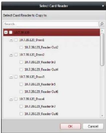
- Click Save buon to save parameters.
7.8.3 Open Door with First Card
Purpose:
You can set mulple rst cards for one access control point. Aer the rst card swiping, it allows mulple persons access the door or other authencaon acons. The rst card mode contains Remain Open with First Card, Disable Remain Open with First Card, and First Card Authorizaon.
Remain Open with First Card: The door remains open for the congured me duraon aer the rst card swiping unl the remain open duraon ends.
First Card Authorizaon: All authencaons, except for the authencaons of super card, duress card, and duress code, are allowed only aer the rst card authorizaon.
Steps:
- Click Open Door with First Card tab to enter the following interface.
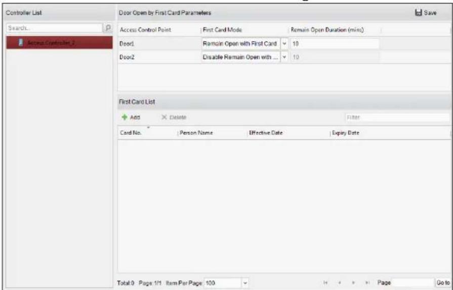
-
Select an access control device from the list on the le.
-
Select the rst card mode in the drop-down list for the access control point.
- (Oponal) If you select Remain Open with First Card, you should set remain open duraon.
Notes:
- The Remain Open Duraon should be between 0 and 1440 minutes. By default, it is 10 minutes.
- In the First Card Authorizaon mode, you can access the door when swiping the super card, the duress card or input the duress code without swiping the rst card.
- You can swipe the rst card again to disable the rst card mode.
-
The rst card authorizaon is effective only on the current day. The authorizaon will be expired aer 24:00 on the current day.
-
In the First Card list, Click Add button to pop up the following dialog box.
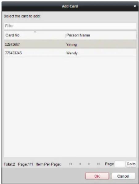
1) Select the cards to add as rst card for the door
Note: Please set the card permission and apply the permission seng to the access control device rst. For details, refer to Chapter 7.7 Permission Conguraon.
2) Click OK buon to save adding the card.
- You can click Delete button to remove the card from the rst card list.
- Click Save to save and take eect of the new setngs.
7.8.4 An-Passing Back
Purpose:
You can set an-passing back for card readers in the same access controller. You should swipe the card according to the congured swiping card route. And only one person could pass the access control point aer swiping the card.
Notes:
- Either the an-passing back or mul-door interlocking funcon can be congured for an access control device at the same me.
- You should enable the an-passing back funcon on the access control device rst.
Seng the Path of Swiping Card (Card Reader Order)
Steps:
- Click An-passing Back tab to enter the following interface.
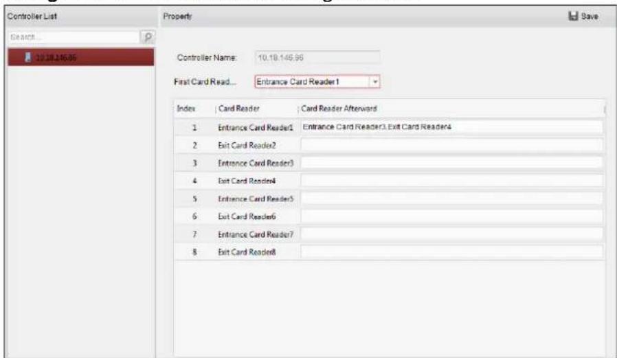
- Select an access control device from the device list on the le.
- In the First Card Reader eld, select the card reader as the beginning of the path.
- In the list, click the text led of Card Reader Aerward and select the linked card readers.
Example: If you select Reader In_01 as the beginning, and select Reader In_02, Reader Out_04 as the linked card readers. Then you can only get through the access control point by swiping the card in the order as Reader In_01, Reader In_02 and Reader Out_04.
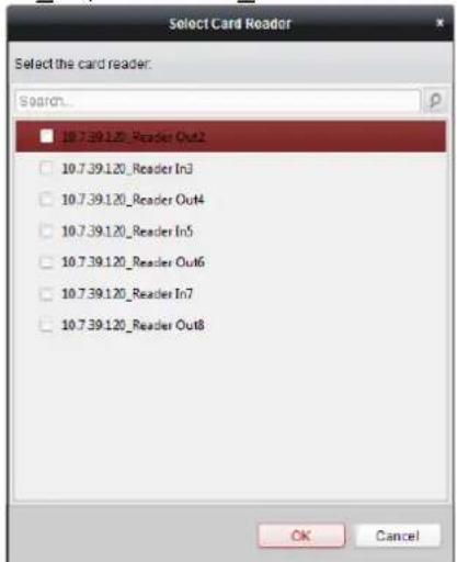
Note: Up to four aerward card readers can be added for one card reader.
- (Oponal) You can enter the Select Card Reader dialog box again to edit its aerward card readers.
- Click Save to save and take eect of the new settings.
7.8.5 Authencaon Password
Purpose:
You can open the door by inpung the authencaon password on the card reader keypad aer nishing the operaon of seng authencaon password.
Notes:
- This authencaon password funcon is only valid during the schedules when the card reader authencaon mode for the access control device is set as Card or Authencaon Password. For details, please refer to Chapter 7.8.2 Card Reader Authenticaon.
● This funcon should be supported by the access control device.
Steps:
- Click Authencaon Password tab and select an access control device from the list.
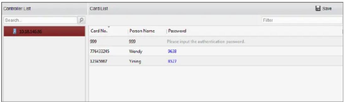
All the cards and persons which have been applied to the device will be displayed.
Note: For seng and applying the permissions to the device, refer to Chapter 7.7 Permission Conguraon.
- Click the Password eld of the card and input the authencaon password for the card.
Note: The authencaon password should contain 4 to 8 digits. - Aer seng the authencaon password, the authencaon password funcon of the card will be enabled by default.
- (Oponal) You can input the keywords of card No., person name, or authencaon password to search.
Notes:
- Up to 500 cards with authencaon password can be added to one access control device.
- The password should be unique and cannot be the same with super password, duress code, and dismiss code in the access control parameters.
7.8.6 Custom Wiegand
Purpose:
Based on the knowledge of uploading rule for the third party wiegand, you can set mulple customized wiegand protocols to communicate between the controller and the third party card readers.
Before you start:
Wire the third party card readers to the controller.
Steps:
- Click Custom Wiegand to enter the Custom Wiegand tab.
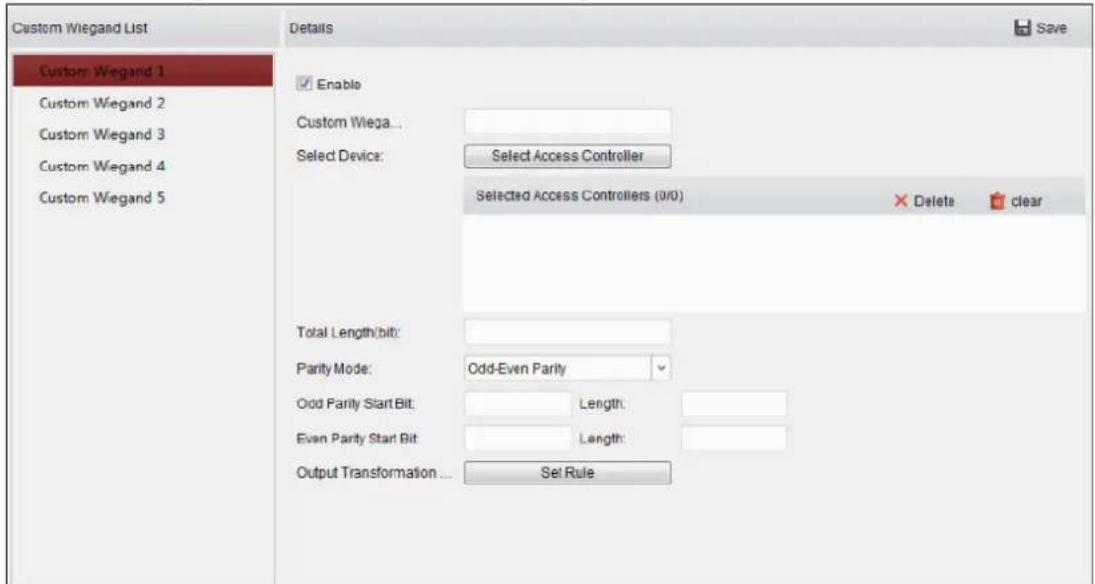
- Select a custom wiegand on the le of the interface.
- Check Enable checkbox to enable the custom wiegand.
- Set the wiegand name.
- Select device.
1) Click Select Device.
2) Select the device need to use custom wiegand.
3) Click OK to save the sengs.
- Input the Total Length and select the parity mode in the drop-down list.
If you select Odd-Even Parity, you should set the odd parity start bit, the odd parity length, the even parity start bit and the even parity length.
If you select XOR Parity, you should set the XOR parity start bit, length per group and total length.
If you select None, you are no need to set the parity mode.
- Set output transformaon rule.
1) Click Set Rule to pop up the Set Output Transformaon Rules window.
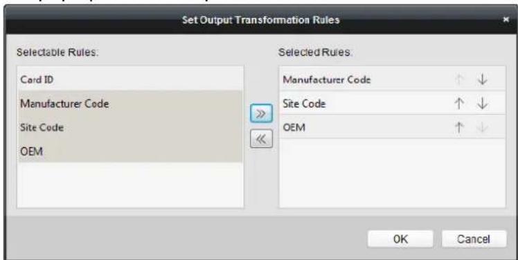
2) Select rules on the le list.
Note: Press the Shi key to select mulple rules.
3) Click to move the selected rules to the right list.
4) (Oponal) Click or to change the rule order.
5) (Oponal) Select the rules in the Selected Rule list and click to remove the rule from the list on the right.
6) Click OK to save the sengs.
7) In the Custom Wiegand tab, set the rule start bit, length, and the decimal digit.
- Click Save at the upper right corner of the interface to save the sengs.
Notes:
- By default, the device disables the custom wiegand funcon.
- If the device enables the custom wiegand funcon, all wiegand interfaces in the device will use the customized wiegand protocol.
- Up to 5 custom wiegands can be set.
- Up to 32 characters are allowed in the custom wiegand name.
- Up to 80 bits are available in the total length.
- The odd parity start bit, the odd parity length, the even parity start bit and the even parity length range from 1 to 80 bit.
- The start bit of the card ID, the manufacturer code, the site code, and the OEM should range from 1 to 80 bit.
- For details about the custom wiegand, see Appendix.
7.9 Searching Access Control Event
Purpose:
You can search the access control history events including device excepon event, door event, alarm input, and card reader event.
Click Icon and click Access Control Event tab to enter the following interface.
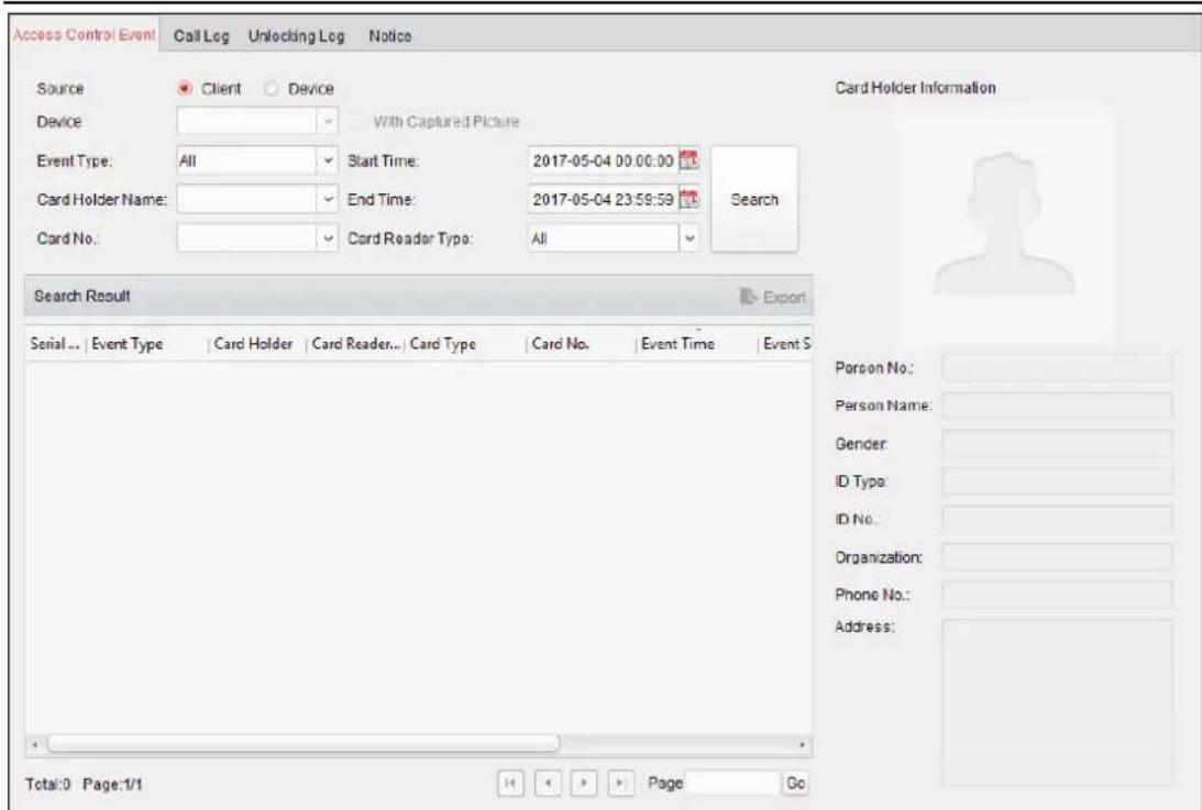
Steps:
- Select the source.
You can select Client or Device. - Enter the search condition (source, event type/card holder name/card No./capture/start & end me).
- Click Search to get the search results.
- View the event informaon in the event list.
- Click an event to view the informaon of the card holder on the Card Holder Informaon panel on the le side of the page.
- You can click Export buon to export the search results to the local PC.
7.10 Access Control Event Configuration
Purpose:
For the added access control device, you can conjure its access control linkage including access control event linkage, access control alarm input linkage, event card linkage, and cross-device linkage.
Click the icon on the control panel, or click Tool->Event Management to open the Event Management page.
7.10.1 Access Control Event Linkage
Purpose:
You can assign linkage acons to the access control event by seng up a rule. For example, when the access control event is detected, an audible warning appears or other linkage acons happen.
Note: The linkage here refers to the linkage of the client soware's own acons.
Steps:
-
Click the Access Control Event tab.
-
The added access control devices will display in the Access Control Device panel on the left. Select the access control device, or alarm input, or access control point (door), or card reader to conjure the event linkage.
-
Select the event type to set the linkage.
-
Select the triggered camera. The image or video from the triggered camera will pop up when the selected event occurs.
To capture the picture of the triggered camera when the selected event occurs, you can also set the capture schedule and the storage in Storage Schedule.
-
Check the checkboxes to acvate the linkage acons. For details, refer to Table 14.1 Linkage Acons for Access Control Event.
-
Click Save to save the sengs.
-
You can click Copy to button to copy the access control event to other access control device, alarm input, access control point, or card reader.
Select the parameters for copy, select the target to copy to, and click OK to conrm.
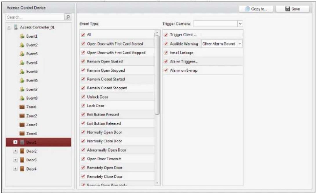
Table 1.1 Linkage Actions for Access Control Event
| Linkage Acons | Descripons |
| Audible Warning | The client soware gives an audible warning when alarm is triggered. You can select the alarm sound for audible warning. |
| Email Linkage | Send an email nocaon of the alarm informaon to one or more receivers. |
| Alarm on E-map | Display the alarm informaon on the E-map.Note: This linkage is only available to access control point an alarm input. |
| Alarm TriggeredPop-up Image | The image with alarm informaon pops up when alarm is triggered. |
7.10.2 Access Control Alarm Input Linkage
Purpose:
The access control alarm inputs can be linked to some acons (e.g., alarm output, host buzzer) when it is triggered.
Note: The linkage here refers to the linkage of the client soware's own acons.
Steps:
- Click Access Control Alarm Input tab to enter the following interface.
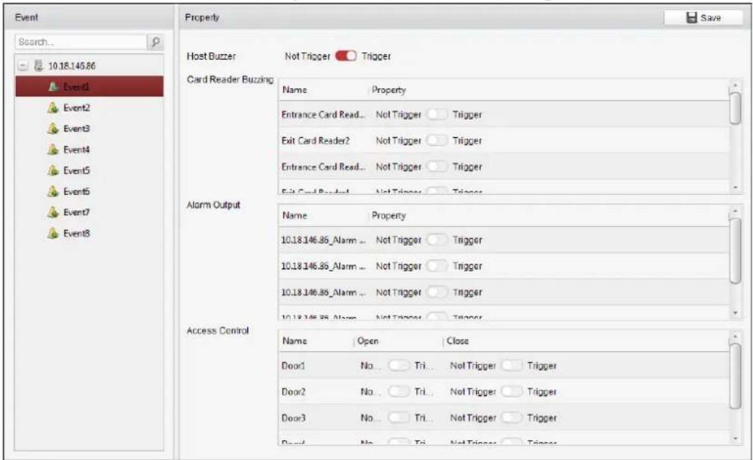
-
In the event list on the le, select an alarm input.
-
Switch the property from to to enable this acon.
Host Buzzer: The audible warning of controller will be triggered.
Card Reader Buzzer: The audible warning of card reader will be triggered.
Alarm Output: The alarm output will be triggered for nocaon.
Access Control Point (Open/Close): The door will be open or closed when the case is triggered.
Note: The Door cannot be congured as open or closed at the same me.
- Click Save buon to save the sengs.
7.10.3 Event Card Linkage
Click Event Card Linkage tab to enter the following interface.
Notes:
● The Event Card Linkage should be supported by the device.
- The linkage here refers to the linkage of the client soware's own acons.
Select the access control device from the list on the le.
Click Add buon to add a new linkage. You can select the event source as Event Linkage or Card Linkage.
Event Linkage
For the event linkage, the alarm event can be divided into four types: device event, alarm input, door event, and card reader event.
Steps:
-
Click to select the linkage type as Event Linkage, and select the event type from the dropdown list.
-
For Device Event, select the detailed event type from the dropdown list.
- For Alarm Input, select the type as alarm or alarm recovery and select the alarm input name from the table.
- For Door Event, select the detailed event type and select the source door from the table.
-
For Card Reader Event, select the detailed event type and select the card reader from the table.
-
Set the linkage target, and switch the property from to to enable this funcon.
-
Host Buzzer: The audible warning of controller will be enabled/disabled.
● Capture: The real-me capture will be enabled. - Card Reader Buzzer: The audible warning of card reader will be enabled/disabled.
● Alarm Output: The alarm output will be enabled/disabled for nocaon. - Access Control Point: The door status of open, close, remain open, and remain closed will be enabled.
Notes:
-
The door status of open, close, remain open, and remain close cannot be triggered at the same me.
● The target door and the source door cannot be the same one. -
Click Save buon to save and take effect of the parameters.
Card Linkage
Steps:
- Click to select the linkage type as Card Linkage.
- Input the card No. or select the card from the dropdown list.
- Select the card reader from the table for triggering.
-
Set the linkage target, and switch the property from to to enable this funcon.
-
Host Buzzer: The audible warning of controller will be enabled/disabled.
● Capture: The real-me capture will be enabled. - Card Reader Buzzer: The audible warning of card reader will be enabled/disabled.
● Alarm Output: The alarm output will be enabled/disabled for nocaon. -
Access Control Point: The door status of open, close, remain open, and remain closed will be enabled.
-
Click Save buon to save and take effect of the parameters.
7.10.4 Cross-Device Linkage
Purpose:
You can assign to trigger other access control device's acon by seng up a rule when the access control event is triggered.
Click Cross-Device Linkage tab to enter the following interface.
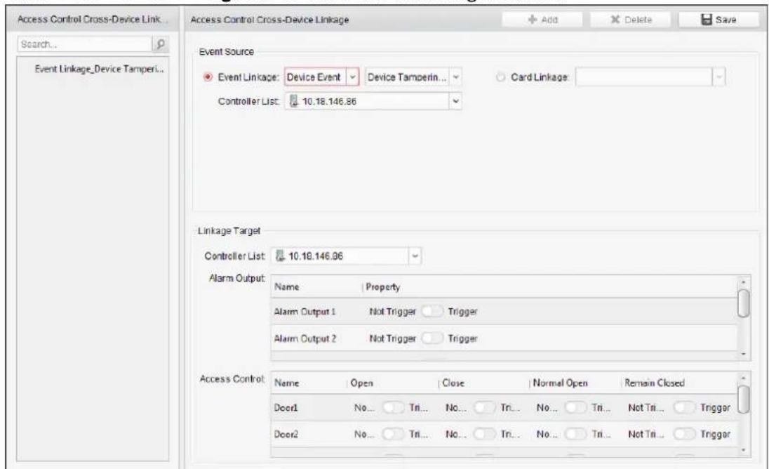
Click Add buon to add a new client linkage. You can select the event source as Event Linkage or Card Linkage.
Event Linkage
For the event linkage, the alarm event can be divided into four types: device event, alarm input, door event, and card reader event.
Steps:
-
Click to select the linkage type as Event Linkage, select the access control device as event source, and select the event type from the dropdown list.
-
For Device Event, select the detailed event type from the dropdown list.
- For Alarm Input, select the type as alarm or alarm recovery and select the alarm input name from the table.
● For Door Event, select the detailed event type and select the door from the table. -
For Card Reader Event, select the detailed event type and select the card reader from the table.
-
Set the linkage target, select the access control device from the dropdown list as the linkage target, and switch the property from to to enable this funcon.
● Alarm Output: The alarm output will be triggered for nocaon.
- Access Control Point: The door status of open, close, remain open, and remain close will be triggered. Note: The door status of open, close, remain open, and remain close cannot be triggered at the same me.
- Click Save buon to save parameters.
Card Linkage
Steps:
- Click to select the linkage type as Card Linkage.
- Select the card from the dropdown list and select the access control device as event source.
- Select the card reader from the table for triggering.
- Set the linkage target, select the access control device from the dropdown list as the linkage target, and switch the property from to to enable this funcon.
Alarm Output: The alarm output will be triggered for nocaon. - Click Save buon to save parameters.
7.11 Door Status Management
Purpose:
The door status of the added access control device will be displayed in real me. You can check the door status and the linked event(s) of the selected door. You can control the status of the door and set the status duraon of the doors as well.
7.11.1 Access Control Group Management
Purpose:
Before controlling the door status and seng the status duraon, you are required to organize it into group for convenient management.
Perform the following steps to create the group for the access control device:
Steps:
- Click on the control panel to open the Device Management page.
- Click Group tab to enter the Group Management interface.
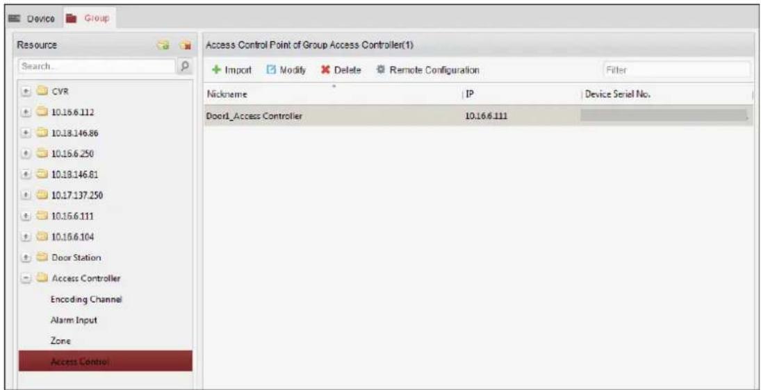
- Perform the following steps to add the group.
1) Click to open the Add Group dialog box.
2) Input a group name as you want.
3) Click OK to add the new group to the group list.
You can also check the checkbox Create Group by Device Name to create the new group by the name of the selected device.
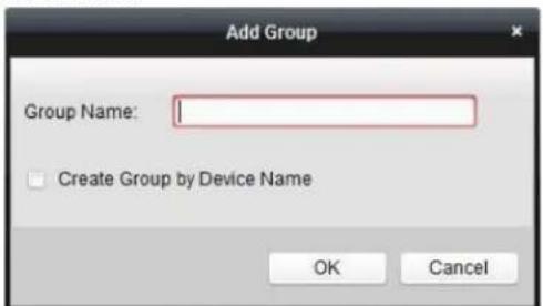
- Perform the following steps to import the access control points to the group:
1) Click Import on Group Management interface, and then click the Access Control tab to open the Import Access Control page.
Notes:
- You can also select Alarm Input tab and import the alarm inputs to group.
- For the Video Access Control Terminal, you can add the cameras as encoding channel to the group.
2) Select the names of the access control points in the list.
3) Select a group from the group list.
4) Click Import to import the selected access control points to the group.
You can also click Import All to import all the access control points to a selected group.
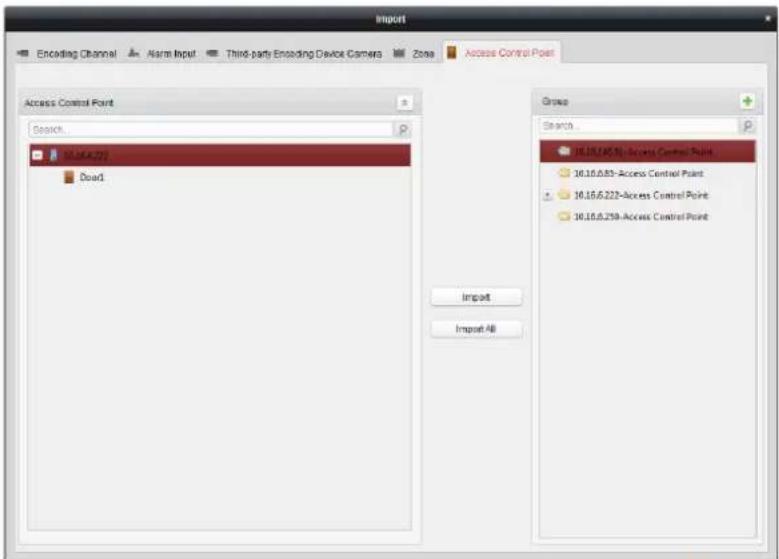
- Aer imporg the access control points to the group, you can click , or double-click the group/access control point name to modify it.
7.11.2 An-control the Access Control Point (Door)
Purpose:
You can control the status for a single access control point (a door), including opening door, closing door, remaining open, and remaining closed.

Click icon on the control panel to enter the Status Monitor interface.
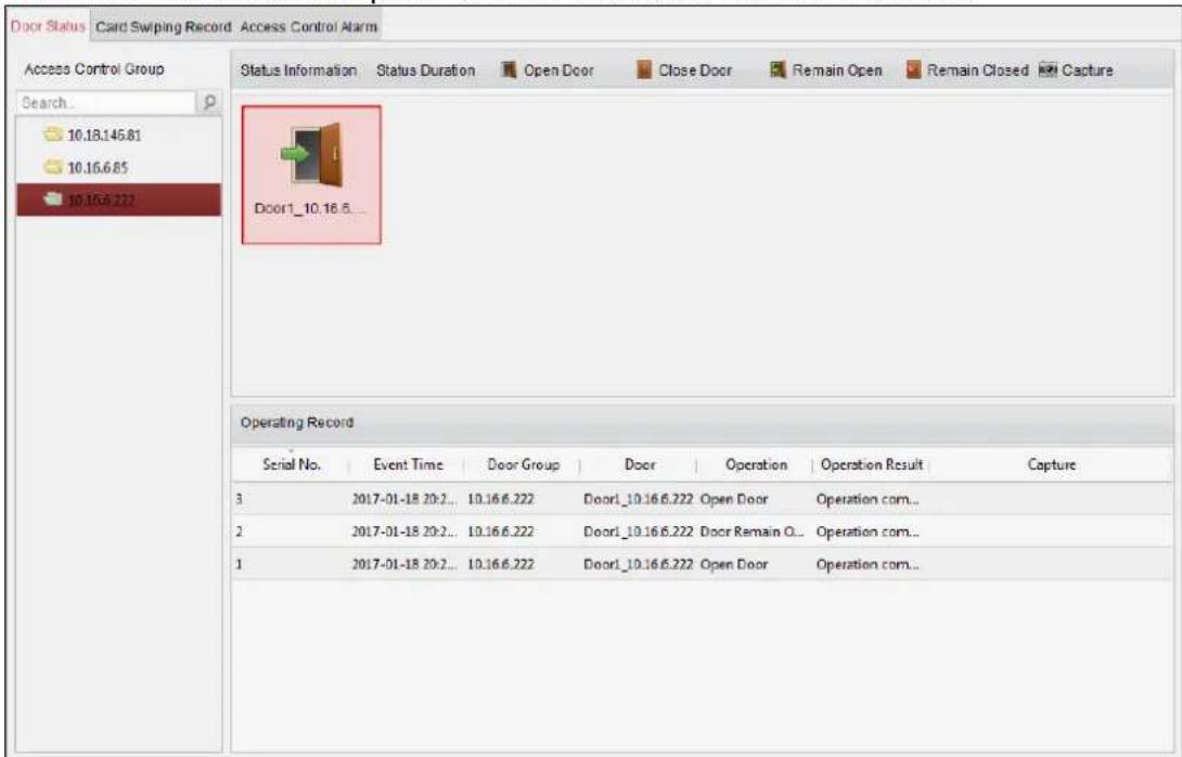
Steps:
- Select an access control group on the le. For managing the access control group, refer to Chapter 7.11.1 Access Control Group Management.
- The access control points of the selected access control group will be displayed on the right.
Click icon on the Status Informaon panel to select a door.
- Click the following buon listed on the Status Informaon panel to control the door.
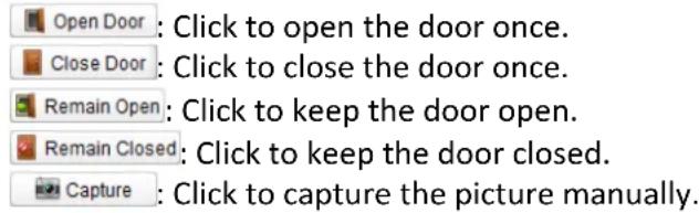
- You can view the an-control operaon result in the Operaon Log panel.
Notes:
- If you select the status as Remain Open/Remain Closed, the door will keep open/closed until a new an-control command being made.
- The Capture buon is available when the device supports capture funcon. And it cannot be realized until the storage server is congured.
- If the door is in remain closed status, only super card can open the door or open door via the client soware.
7.11.3 Status Duraon Conguraon
Purpose:
You can schedule weekly me periods for an access control point (door) to remain open or remain closed.
In the Door Status module, click Status Duraon buon to enter the Status Duraon interface.
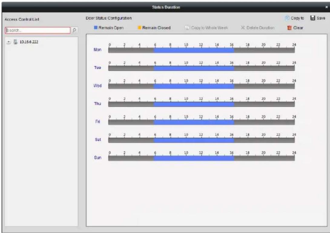
bar_stacked
| Day | Remain Open | Remain Closed | Copy to Whole Week | Delete Duration | Clear | |-------|-------------|---------------|--------------------|-----------------|-------| | Mon | 0 | 0 | 0 | 18 | 24 | | Tue | 0 | 2 | 4 | 10 | 24 | | Wed | 0 | 2 | 4 | 10 | 24 | | Thu | 0 | 2 | 4 | 10 | 24 | | Fri | 0 | 2 | 4 | 10 | 24 | | Sat | 0 | 2 | 4 | 10 | 24 | | Sun | 0 | 2 | 4 | 10 | 24 |Steps:
- Click to select a door from the access control device list on the le.
- On the Door Status Conguraon panel on the right, draw a schedule for the selected door.
1) Select a door status brush as


Remain Open: The door will keep open during the congured me period. The brush is marked as
Remain Closed: The door will keep closed during the congured duration. The brush is marked as
2) Click and drag on the meline to draw a color bar on the schedule to set the duraon.
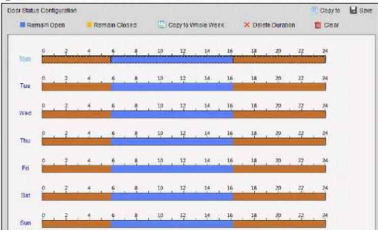
bar_stacked
Door Status Configuration | Day | Remain Open | Remain Closed | Copy to Whole Week | Delete Duration | Clear | |---|---|---|---|---|---| | Mon | 0 | 0 | 0 | 18 | 24 | | Tue | 0 | 2 | 4 | 18 | 24 | | Wed | 0 | 2 | 4 | 18 | 24 | | Thu | 0 | 2 | 4 | 18 | 24 | | Fri | 0 | 2 | 4 | 18 | 24 | | Sat | 0 | 2 | 4 | 18 | 24 | | Sun | 0 | 2 | 4 | 18 | 24 |3) When the cursor turns to 📄, you can move the selected me bar you just edited. You can also edit the displayed me point to set the accurate me period.
When the cursor turns to ↩, you can lengthen or shorten the selected me bar.
- Oponally, you can select the schedule me bar and click Copy to Whole Week to copy the
me bar sengs to the other days in the week.
- You can select the me bar and click Delete Duraon to delete the me period.
Or you can click Clear to clear all congured duraons on the schedule.
- Click Save to save the sengs.
- You can click Copy to buon to copy the schedule to other doors.
7.11.4 Real-me Card Swiping Record
Click Card Swiping Record tab to enter the following interface.
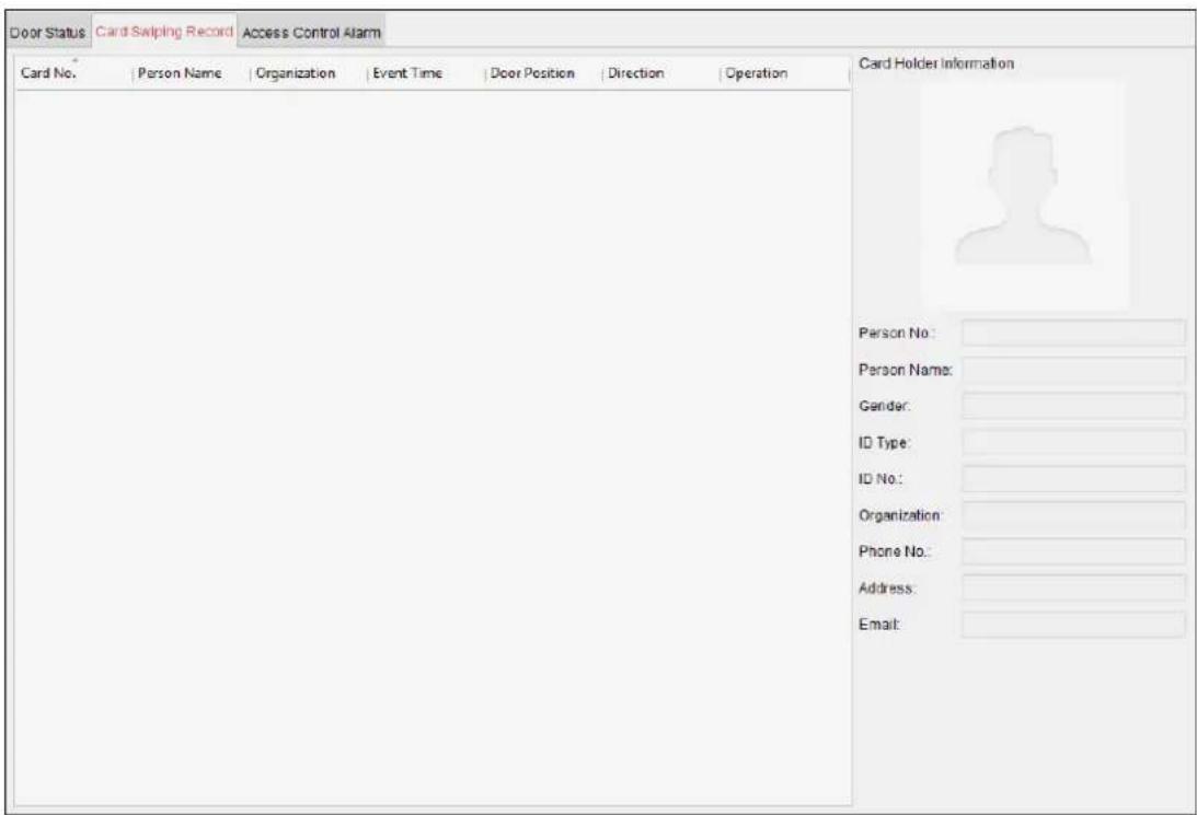
The logs of card swiping records of all access control devices will display in real me. You can view the details of the card swiping event, including card No., person name, organizaon, event me, etc.
You can also click the event to view the card holder details, including person No., person name, organizaon, phone, contact address, etc.
7.11.5 Real-me Access Control Alarm
Purpose:
The logs of access control events will be displayed in real me, including device excepon, door event, card reader event, and alarm input.
Click Access Control Alarm tab to enter the following interface.
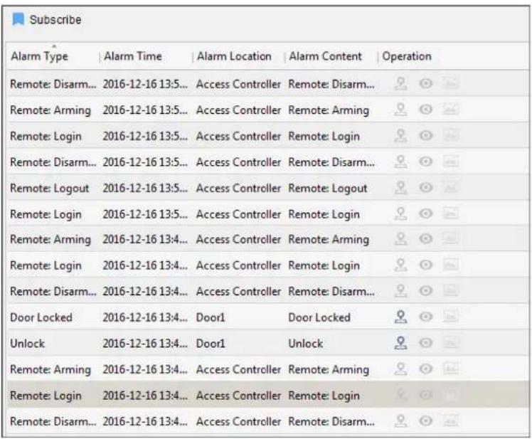
Steps:
- All access control alarms will display in the list in real me.
You can view the alarm type, alarm me, locaon, etc.
-
Click 🔒 to view the alarm on E-map.
-
You can click or to view the live view or the captured picture of the triggered camera when the alarm is triggered.
Note: For seng the triggered camera, refer to Chapter 7.10.1 Access Control Event Linkage.
- Click Subscribe to select the alarm that the client can receive when the alarm is triggered.
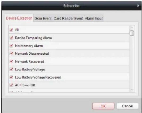
1) Check the checkbox(es) to select the alarm(s), including device excepon alarm, door event alarm, card reader alarm, and alarm input.
2) Click OK to save the sengs.
7.12 Arming Control
Purpose:
You can arm or disarm the device. Aer arming the device, the client can receive the alarm informaon from the device.
Steps:
-
Click Tool->Device Arming Control to pop up the Device Arming Control window.
-
Arm the device by checking the corresponding checkbox.
Then the alarm informaon will be auto uploaded to the client soware when alarm occurs.
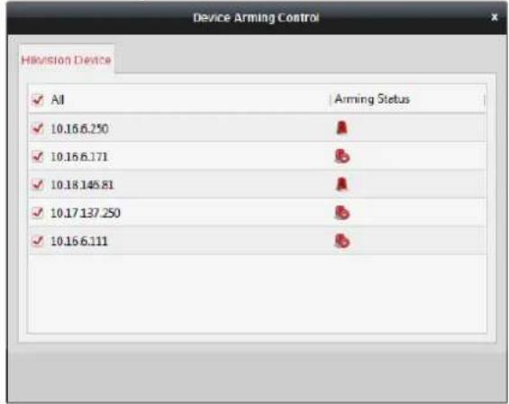
Appendix A Sound Prompt and Indicator
Aer the card reader is powered on, LED status indicator will turn blue and blink for 1 me. Then it will turn red and blink for 3 mes. At last the buzzer will send out a beep sound indicang the starng up process is completed.
During using the card reader, it will send out dierent sounds prompt and the LED indicator on it have different statuses. You can refer to tables below for detailed informaon.
Table 7-1 Descripon of Prompt Sound
| Sound Prompt | Descripon |
| One beep | RS-485 protocol: Pressing keys prompt; Swiping card prompt; Tim out prompt for pressing keys or swiping card.Wiegand protocol: Pressing keys prompt; Swiping card prompt. |
| Two rapid beeps | The operaon of pressing keys or swiping card is valid. |
| Three slow beeps | The operaon of pressing keys or swiping card is invalid. |
| Rapidly connuous beeps | Alarm of tamper-proof. |
| Slowly connuous beeps | The card reader is unencrypted. |
Table 7-2 Descripon of LED Indicator
| LED Indicator Status | Descripon |
| Green and blinking | Card reader is working normally. |
| Solid green | The operaon of pressing keys or swiping card is valid. |
| Solid red | The operaon of pressing keys or swiping card is invalid. |
| Red and blinking | For RS-485 protocol: Registering failed or card reader is oine. Failed to get key les of PSAM card; Failed to detect the PSAM card. |
| Red and Keeping rapidly blinking | Available for reading le mode of CPU card: PSAM is not inserted or undetected. |
Appendix B Custom Wiegand Rule
Take Wiegand 44 as an example, the seng values in the Custom Wiegand tab are as follows:
| Custom Wiegand Name: | Wiegand 44 | |||||
| Total Length | 44 | |||||
| Transformaon Rule (Decimal Digit) | byFormatRule[4]=[1][4][0][0] | |||||
| Parity Mode | XOR Parity | |||||
| Odd Parity Start Bit | Length | |||||
| Even Parity Start Bit | Length | |||||
| XOR Parity Start Bit | 0 | Length per Group | 4 | Total Length | 40 | |
| Card ID Start Bit | 0 | Length | 32 | Decimal Digit | 10 | |
| Site Code Start Bit | Length | Decimal Digit | ||||
| OEM Start Bit | Length | Decimal Digit | ||||
| Manufacturer Code Start Bit | 32 | Length | 8 | Decimal Digit | 3 | |
Wiegand Data = Valid Data + Parity Data
Total Length: Wiegand data length.
Transportation Rule: 4 bytes. Display the combination types of valid data. The example displays the combination of Card ID and Manufacturer Code. The valid data can be single rule, or combinaon of mulple rules.
Parity Mode: Valid parity for wiegand data. You can select either odd parity or even parity.
Odd Parity Start Bit, and Length: If you select Odd Parity, these items are available. If the odd parity start bit is 1, and the length is 12, then the system will start odd parity calculaon from bit 1. It will calculate 12 bits. The result will be in bit 0. (Bit 0 is the rst bit.)
Even Parity Start Bit, and Length: If you select Even Parity, these items are available. If the even parity start bit is 12, and the length is 12, then the system will start even parity calculaon from bit 12. It will calculate 12 bits. The result will be in the last bit.
XOR Parity Start Bit, Length per Group, and Total Length: If you select XOR Parity, these items are available. Depending on the table displayed above, the start bit is 0, the length per group is 4, and the total length is 40. It means that the system will calculate from bit 0, calculate every 4 bit, and calculate 40 bits in total (10 groups in total). The result will be in the last 4 bits. (The result length is the same as the length per group.)
Card ID Start Bit, Length, and Decimal Digit: If you use the transformation rule, these items are available. Depending on the table displayed above, the card ID start bit is 0, the length is 32, and the decimal digit is 10. It represents that from bit 0, there are 32 bits represent the card ID. (The length here is calculated by bit.) And the decimal digit length is 10 bits.
Site Code Start Bit, Length, and Decimal Digit: If you use the transformation rule, these items are available. For detailed informaon, see the explanaon of the card ID.
OEM Start Bit, Length, and Decimal Digit: If you use the transformaon rule, these items are available. For detailed informaon, see the explanaon of the card ID.
Manufacturer Code Start Bit, Length, and Decimal Digit: If you use the transformaon rule, these items are available. Depending on the table displayed above, the manufacturer code start bit is 32, length is 8, and decimal digit is 3. It represents that from bit 32, there are 8 bits are manufacturer code. (The length here is calculated by bit.) And the decimal length is 3.
020000001080620

See Far, Go Further

- DS-K2800 Series Access Controller
- User Manual
- About this Manual
- Trademarks
- Disclaimer
- Support
- Regulatory Informaon
- FCC Informaon
- FCC Conditions
- EU Conformity Statement
- Industry Canada ICES-003 Compliance
- Prevenve and Cauonary Tips
- Safety Instrucon
- Warnings
- Cauons
- Table of Contents
- Chapter 1 Product Descripon ....1
- Chapter 2 Component Descripon ......2
- Chapter 3 Terminal Connecon....3
- Chapter 4 External Device Wiring ....10
- Chapter 5 Setngs ......14
- Chapter 6 Acvang the Access Control Terminal....17
- Chapter 7 Client Operaon ....21
- Person and Card Management 39
- Schedule and Template....48
- Permission Conguraon....53
- Advanced Funcons....55
- Searching Access Control Event 64
- Access Control Event Conguraon 65
- Door Status Management....70
- Arming Control....76
- Appendix A Sound Prompt and Indicator 78
- Appendix B Custom Wiegand Rule....79
- Chapter 1 Product Description
- Overview
- Main Features
- Chapter 2 Component Description
- Chapter 3 Terminal Connection
- DS-K2801 Terminal Description
- Notes:
- Chapter 4 External Device Wiring
- Card Reader Wiring
- Wiegand Card Reader Wiring
- DS-K1800 Series Card Reader Wiring
- DS-K2801 External Terminals
- Installaon of Cathode Lock
- Installaon of Anode Lock
- Connecting the External Alarm Device
- Door Button Wiring Diagram
- The Connection of Magnetics Detection
- Connecting Power Supply
- Chapter 5 Settings
- Initializing the Hardware
- Opon 1:
- Steps:
- Opon 2:
- Relay Input NO/NC
- Lock Relay Output
- Alarm Relay Output Status
- Work Flow of Soware
- Chapter 6 Activating the Access Control Terminal
- Purpose:
- Activating via SADP Software
- Activating via Client Software
- Chapter 7 Client Operation
- Function Module
- Control Panel of iVMS-4200:
- User Registration and Login
- System Configuration
- Access Control Management
- Before you start:
- Adding Access Control Device
- Creang Password
- Adding Online Device
- Adding Mulple Online Device
- Adding All Online Devices
- Adding Devices by IP or Domain Name
- Adding Devices by IP Segment
- Imporng Devices in Batch
- Viewing Device Status
- Eding Basic Informaon
- Remote Conguraon
- Checking Device Informaon
- Eding Device Name
- Eding Time
- Seng System Maintenance
- Managing User
- Seng Security
- Click System -> Security.
- Conguring Network Parameters
- Conguring Advanced Network
- Conguring Relay Parameters
- Conguring Access Control Parameters
- Conguring Face Detecon Parameters
- Operang Relay
- Viewing Relay Status
- Person and Card Management
- Organizaon Management
- Adding Organizaon
- Modifying and Deleng Organizaon
- Person Management
- Adding Person
- Adding Person (Basic Informaon)
- Adding Person (Detailed Informaon)
- Click OK to save the sengs.
- Adding Person (Permission)
- Click OK to save the sengs.
- Adding Person (Card)
- Adding Person (Aendance Rule)
- Imporng and Exporng Person Informaon
- Geng Person Informaon from Access Control Device
- Managing Person
- Modifying and Deleng Person
- Changing Person to Other Organizaon
- Issuing Card in Batch
- Schedule and Template
- Week Schedule
- Holiday Group
- Template
- Permission Configuration
- Adding Permission
- Applying Permission
- Advanced Functions
- Click
- Access Control Parameters
- Door Parameters
- Card Reader Parameters
- Card Reader Authencaon
- Open Door with First Card
- An-Passing Back
- Seng the Path of Swiping Card (Card Reader Order)
- Authencaon Password
- Custom Wiegand
- Searching Access Control Event
- Access Control Event Configuration
- Access Control Event Linkage
- Access Control Alarm Input Linkage
- Event Card Linkage
- Event Linkage
- Card Linkage
- Cross-Device Linkage
- Door Status Management
- Access Control Group Management
- An-control the Access Control Point (Door)
- Status Duraon Conguraon
- Real-me Card Swiping Record
- Real-me Access Control Alarm
- Arming Control
- Appendix A Sound Prompt and Indicator
- Appendix B Custom Wiegand Rule
Brand : Hikvision
Model : DS-K2800
Category : Système de contrôle d'accès sécurisé