VigorLTE 200n - Router Draytek - Free user manual and instructions
Find the device manual for free VigorLTE 200n Draytek in PDF.


User questions about VigorLTE 200n Draytek
0 question about this device. Answer the ones you know or ask your own.
Ask a new question about this device
Download the instructions for your Router in PDF format for free! Find your manual VigorLTE 200n - Draytek and take your electronic device back in hand. On this page are published all the documents necessary for the use of your device. VigorLTE 200n by Draytek.
USER MANUAL VigorLTE 200n Draytek
natural_image
White Vigo/LTE 200s router with two antennas and ventilation slots (no visible text or symbols on body)USER'S GUIDE
V1.2
VigorLTE 200 Series LTE Router
User's Guide
Version: 1.2
(For future update, please visit DrayTek web site)
Date: Dec. 12, 2022
Copyrights
© All rights reserved. This publication contains information that is protected by copyright. No part may be reproduced, transmitted, transcribed, stored in a retrieval system, or translated into any language without written permission from the copyright holders.
Trademarks
The following trademarks are used in this document:
● Microsoft is a registered trademark of Microsoft Corp.
● Windows, Windows 8, 10, 11 and Explorer are trademarks of Microsoft Corp.
● Apple and Mac OS are registered trademarks of Apple Inc.
● Other products may be trademarks or registered trademarks of their respective manufacturers.
Safety Instructions
- Read the installation guide thoroughly before you set up the router.
- The router is a complicated electronic unit that may be repaired only be authorized and qualified personnel. Do not try to open or repair the router yourself.
- Do not place the router in a damp or humid place, e.g. a bathroom.
● The router should be used in a sheltered area, within a temperature range of +5 to +40 Celsius. - Do not expose the router to direct sunlight or other heat sources. The housing and electronic components may be damaged by direct sunlight or heat sources.
- Do not deploy the cable for LAN connection outdoor to prevent electronic shock hazards.
- Keep the package out of reach of children.
- When you want to dispose of the router, please follow local regulations on conservation of the environment.
Warranty
We warrant to the original end user (purchaser) that the router will be free from any defects in workmanship or materials for a period of two (2) years from the date of purchase from the dealer. Please keep your purchase receipt in a safe place as it serves as proof of date of purchase. During the warranty period, and upon proof of purchase, should the product have indications of failure due to faulty workmanship and/or materials, we will, at our discretion, repair or replace the defective products or components, without charge for either parts or labor, to whatever extent we deem necessary tore-store the product to proper operating condition. Any replacement will consist of a new or re-manufactured functionally equivalent product of equal value, and will be offered solely at our discretion. This warranty will not apply if the product is modified, misused, tampered with, damaged by an act of God, or subjected to abnormal working conditions. The warranty does not cover the bundled or licensed software of other vendors. Defects which do not significantly affect the usability of the product will not be covered by the warranty. We reserve the right to revise the manual and online documentation and to make changes from time to time in the contents hereof without obligation to notify any person of such revision or changes.
Be a Registered Owner
Web registration is preferred. You can register your Vigor router via https://myvigor.draytek.com.
Firmware & Tools Updates
Due to the continuous evolution of DrayTek technology, all routers will be regularly upgraded. Please consult the DrayTek web site for more information on newest firmware, tools and documents.
https://www.draytek.com
Table of Contents
Part I Installation....i
I-1 Introduction ...... 1
I-1-1 Indicators and Connectors 2
I-2 Hardware Installation 4
I-2-1 Network Connection via LTE 4
I-2-2 Wall-Mounted Installation 5
I-3 Accessing Web Page 6
I-4 Changing Password....8
I-5 Dashboard....9
I-5-1 Virtual Panel 10
I-5-2 Name with a Link.... 10
I-5-3 Quick Access for Common Used Menu 11
I-5-4 GUI Map 12
I-5-5 Web Console 13
I-5-6 Config Backup 13
I-5-7 Logout.... 14
I-5-8 Online Status 14
I-5-8-1 Physical Connection.... 14
I-5-8-2 Virtual WAN 16
I-6 Quick Start Wizard 17
I-6-1 LTE 18
I-6-2 WAN2 (Ethernet) 20
I-7 Service Activation Wizard 29
I-8 Registering Vigor Router.... 31
Part II Connectivity ....35
II-1 LTE 36
Web User Interface 37
II-1-1 General Settings.... 37
II-1-1-1 SMS Quota....37
II-1-1-2 SMS Inbox Policy....38
II-1-2 SMS Inbox 39
II-1-3 Send SMS 42
II-1-4 SMS Gateway.... 43
II-1-5 Router Commands 47
II-1-6 Status 49
II-2 WAN....51
Web User Interface 52
II-2-1 General Setup 52
II-2-1-1 LTE 53
II-2-1-2 WAN2....53
II-2-2 Internet Access....55
II-2-2-1 Details Page for 3G/4G LTE Modem (DHCP mode) in LTE WAN....56
II-2-2-2 Details Page for PPPoE in WAN2....61
II-2-2-3 Details Page for Static or Dynamic IP in WAN2 63
II-2-2-4 Details Page for PPTP 67
II-2-2-5 Details Page for IPv6 - Offline 69
II-2-2-6 Details Page for IPv6 - PPP 69
II-2-2-7 Details Page for IPv6 - TSPC 70
II-2-2-8 Details Page for IPv6 - AICCU 72
II-2-2-9 Details Page for IPv6 - DHCPv6 Client 73
II-2-2-10 Details Page for IPv6 - Static IPv6 74
II-2-2-11 Details Page for IPv6 - 6in4 Static Tunnel....75
II-2-2-12 Details Page for IPv6 - 6rd ......77
II-2-3 Multi-PVC/VLAN 79
II-2-4 WAN Budget....83
II-2-4-1 General Setup 83
II-2-4-2 Status 85
Application Notes 87
A-1 How to configure IPv6 on WAN interface?......87
II-3 LAN 92
Web User Interface 94
II-3-1 General Setup 94
II-3-1-1 Details Page for LAN1 - Ethernet TCP/IP and DHCP Setup....96
II-3-1-2 Details Page for LAN2....98
II-3-1-3 Details Page for IP Routed Subnet 100
II-3-1-4 Details Page for LAN IPv6 Setup.... 102
II-3-1-5 DHCP Server Options 105
II-3-2 VLAN 107
II-3-3 Bind IP to MAC....110
II-4 NAT 113
Web User Interface 114
II-4-1 Port Redirection.... 114
II-4-2 DMZ Host 118
II-4-3 Open Ports 121
II-4-4 ALG....123
II-5 Applications 125
Web User Interface 126
II-5-1 Dynamic DNS 126
II-5-2 Schedule.... 129
II-5-3 RADIUS 132
II-5-4 UPnP 134
II-5-5 IGMP.... 135
II-5-5-1 General Setting 135
II-5-5-2 Working Group 136
II-5-6 SMS Alert Service 137
Application Notes 138
A-1 How to use DrayDDNS? 138
A-2 How to Configure Customized DDNS? 143
II-6 Routing....147
Web User Interface 148
II-6-1 Static Route 148
II-5-2 Route Policy 153
II-5-3 BGP 162
II-5-3-1 Basic Settings.... 162
II-5-3-2 Static Network 163
Part III Wireless LAN....165
III-1 Wireless LAN 166
Web User Interface 170
III-1-1 Wireless Wizard.... 170
III-1-2 General Setup 173
III-1-3 Security.... 175
III-1-4 Access Control 177
III-1-5 WPS.... 179
III-1-6 WDS 180
III-1-7 Advanced Setting 183
III-1-8 AP Discovery 186
III-1-9 Station List.... 187
Part IV VPN....189
IV-1 VPN and Remote Access 190
Web User Interface 191
IV-1-1 VPN Client Wizard 191
IV-1-2 VPN Server Wizard.... 197
IV-1-3 Remote Access Control 200
IV-1-4 PPP General Setup....202
IV-1-5 IPsec General Setup....204
IV-1-6 IPsec Peer Identity 206
IV-1-7 VPN Matcher Setup 208
IV-1-8 OpenVPN 209
IV-1-8-1 OpenVPN Server Setup 209
IV-1-8-2 Client Config.... 212
IV-1-9 Remote Dial-in User....214
IV-1-10 LAN to LAN 217
IV-1-11 Connection Management.... 227
IV-2 SSL VPN 228
Web User Interface 229
IV-2-1 General Setup.... 229
IV-2-2 User Account.... 230
IV-2-3 SSL Portal Online User 234
IV-3 Certificate Management....235
Web User Interface 236
IV-3-1 Local Certificate 236
IV-3-2 Trusted CA Certificate....240
IV-3-3 Certificate Backup 242
Part V Security 243
V-1 Firewall....244
Web User Interface 246
V-1-1 General Setup....246
V-1-2 Filter Setup.... 251
V-1-3 DoS Defense....261
V-1-3-1 DoS Defense.... 261
V-1-3-2 Spoofing Defense.... 264
Application Notes 265
A-1 How to Configure Certain Computers Accessing to Internet 265
V-2 Central Security Management (CSM).... 269
Web User Interface 270
V-2-1 APP Enforcement Profile 270
V-2-2 URL Content Filter Profile 272
V-2-3 Web Content Filter Profile 276
V-2-4 DNS Filter Profile 280
Application Notes 282
A-1 How to Create an Account for MyVigor 282
A-2 How to Block Facebook Service Accessed by the Users via Web Content Filter / URL
Content Filter 287
Part VI Management ......293
VI-1 System Maintenance 294
Web User Interface 295
VI-1-1 System Status....295
VI-1-2 TR-069 297
VI-1-3 Administrator Password 300
VI-1-4 User Password....301
VI-1-5 Configuration Backup.... 303
VI-1-6 Syslog/Mail Alert 305
VI-1-7 Time and Date....307
VI-1-8 SNMP 308
VI-1-9 Management 310
VI-1-10 Panel Control 314
VI-1-11 Self-Signed Certificate 315
VI-1-12 Reboot System....316
VI-1-13 Firmware Upgrade 317
VI-1-14 Activation....318
VI-2 Bandwidth Management.... 320
Web User Interface 322
VI-2-1 Sessions Limit 322
VI-2-2 Bandwidth Limit 324
VI-2-3 Quality of Service 326
VI-3 Central Management (AP) 331
Web User Interface 332
VI-3-1 Dashboard.... 332
VI-3-2 Status 333
VI-3-3 WLAN Profile.... 334
VI-3-4 AP Maintenance.... 339
VI-3-5 Traffic Graph 340
VI-3-6 Temperature Sensor 341
VI-3-7 Event Log 341
VI-3-8 Total Traffic 342
VI-3-9 Station Number 342
VI-3-10 Load Balance 343
VI-3-11 Function Support List 345
Part VII Others....347
VII-1 Objects Settings.... 348
Web User Interface 349
VII-1-1 IP Object 349
VII-1-2 IP Group 353
VII-1-3 IPv6 Object.... 354
VII-1-4 IPv6 Group 356
VII-1-5 Service Type Object....357
VII-1-6 Service Type Group 359
VII-1-7 Keyword Object.... 361
VII-1-8 Keyword Group 363
VII-1-9 File Extension Object 364
VII-1-10 SMS Service Object 366
VII-1-11 Notification Object 369
VII-1-12 String Object 371
Application Notes 372
A-1 How to Send a Notification to Specified Phone Number via SMS Service in WAN Disconnection 372
Part VIII Troubleshooting ....377
VIII-1 Diagnostics 378
Web User Interface 379
VIII-1-1 Dial-out Triggering....379
VIII-1-2 Routing Table....380
VIII-1-3 ARP Cache Table 381
VIII-1-4 IPv6 Neighbour Table 382
VIII-1-5 DHCP Table 383
VIII-1-6 NAT Sessions Table 384
VIII-1-7 DNS Cache Table 385
VIII-1-8 Ping Diagnosis 386
VIII-1-9 Data Flow Monitor 387
VIII-1-10 Traffic Graph 389
VIII-1-11 Trace Route 390
VIII-1-12 Syslog Explorer 391
VIII-1-13 IPv6 TSPC Status 392
VIII-1-14 DoS Flood Table 393
VIII-2 Checking If the Hardware Status Is OK or Not 394
VIII-3 Checking If the Network Connection Settings on Your Computer Is OK or Not...... 395
VIII-4 Pinging the Router from Your Computer 398
VIII-5 Checking If the ISP Settings are OK or Not 400
VIII-6 Backing to Factory Default Setting If Necessary 401
VIII-7 Contacting DrayTek 402
Part IX Telnet Commands....403
Accessing Telnet of VigorLTE 200....404
Part I Installation

This part will introduce Vigor router and guide to install the device in hardware and software.
I-1 Introduction
This is a generic International version of the user guide. Specification, compatibility and features vary by region. For specific user guides suitable for your region or product, please contact local distributor.
VigorLTE 200 series is a router equipped with an LTE module which allows you to access the Internet via a SIM card.
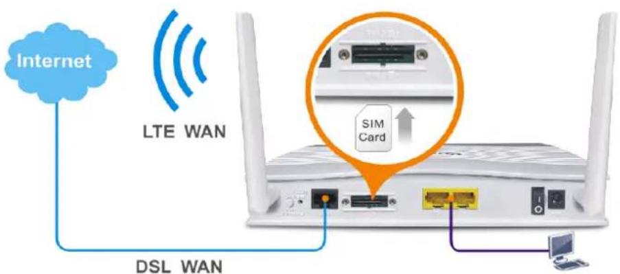
text_image
Internet LTE WAN SIM Card DSL WANIt integrates IP layer QoS, NAT session/ bandwidth management to help users control works well with large bandwidth. By adopting hardware-based VPN platform and hardware encryption of AES/ DES/ 3DES, the router increases the performance of VPN greatly, and offers several protocols (such as IPSec/ PPTP/ L2TP) with VPN tunnels.
The object-based design used in SPI (Stateful Packet Inspection) firewall allows users to set firewall policy with ease. CSM (Content Security Management) provides users control and management in IM (Instant Messenger) and P2P (Peer to Peer) more efficiency than before. By the way, DoS/ DDoS prevention and URL/ Web content filter strengthen the security outside and control inside. Object-based firewall is flexible and allows your network be safe.
On the Wireless-equipped models each of the wireless SSIDs can also be grouped within one of the VLANs.
VigorLTE 200 series provides two-level management to simplify the configuration of network connection. The user mode allows user accessing into WEB interface via simple configuration. However, if users want to have advanced configurations, they can access into WEB interface through admin mode.
I-1-1 Indicators and Connectors
Before you use the Vigor router, please get acquainted with the LED indicators and connectors first.
VigorLTE 200 / VigorLTE 200n

text_image
VigorLTE 200 VigorLTE 200n| LED Status Explanation | ||
| Off The router is powered off. | ||
| Blinking The router is powered on and running normally. | ||
| On The router is ready to access Internet. | ||
| Off The router is not ready to access Internet. | ||
| Blinking Slowly: The DSL connection is ready. Quickly: The DSL connection is establishing. | ||
| On The LAN port is connected. | ||
| Blinking The data is transmitting through the LAN port. | ||
| On LTE device is connected and ready for use. | ||
| Off LTE device is not detected, or has serious problem (e.g., no SIM card, SIM pin error, SIM deactivated, and etc.). | ||
| Blinking Vigor device performs initial access procedure. | ||
| On SIM card is inserted into the slot and detected by Vigor device. | ||
| Blinking No SIM card in detected. | ||
| On Wireless function is enabled. | ||
| Off Wireless function is disabled. | ||
| Blinking The data is transmitting via wireless connection. Blinks with one second cycle for two minutes. The WPS function is active. | ||
VigorLTE 200,
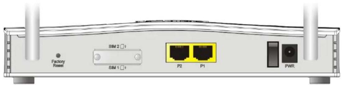
text_image
Factory Reset SIM 2 ? SIM 1 ? P2 P1 PWRVigorLTE 200n,
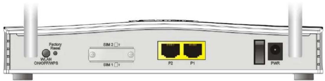
text_image
Factory Reset WLAH ON/OFF/WPS SIM 2 ? SIM 1 ? P2 P1 PWRInterface Description
| Factory Reset | Restore the default settings. Usage: Turn on the router (ACT LED is blinking). Press the hole and keep for more than 5 seconds. When you see the ACT LED begins to blink rapidly than usual, release the button. Then the router will restart with the factory default configuration. |
| SIM2/ SIM1 | SIM card slot(s). |
| P2-P1 | Connecters for local network devices. |
| ON/ OFF | Power Switch. |
| PWR Connector for a power adapter. | |
I-2 Hardware Installation
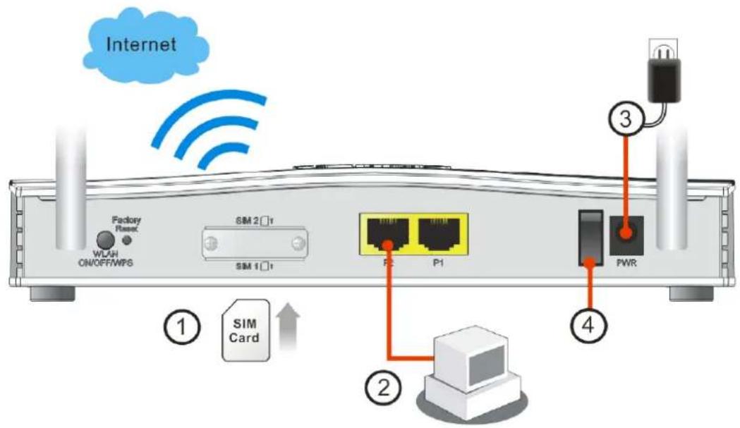
I-2-1 Network Connection via LTE
Before starting to configure the router, you have to connect your devices correctly. In this section, VigorLTE 200 is taken as an example.
- Install the SIM card into the card slot. The back plate of the SIM card slot must be removed first and the direction of card notch must be on the left side.
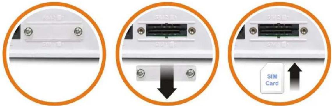
text_image
SIM Card SIM CardAfter installing the SIM card, fasten the back plate again.
- Connect to your computer with a RJ-45 cable.
- Connect one end of the power cord to the power port of this device. Connect the other end to the wall outlet of electricity.
- Power on the router.
- Check the power, LTE and LAN LEDs to assure network connections.
(For the hardware connection, we take "n" model as an example.)
text_image
Internet Factory Reset WLAH ON/OFF/WPS SIM 2 SIM 1 P2 P1 PWR ① SIM Card ② ③ ④I-2-2 Wall-Mounted Installation
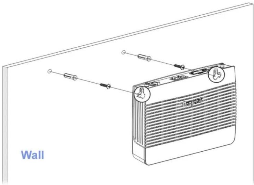
VigorLTE 200 has keyhole type mounting slots on the underside.
- A template is provided on the VigorLTE 200 packaging box to enable you to space the screws correctly on the wall.
- Place the template on the wall and drill the holes according to the recommended instruction.
- Fit screws into the wall using the appropriate type of wall plug.
text_image
Wall
Note
The recommended drill diameter shall be 6.5mm (1/4").
- When you finished about procedure, the router has been mounted on the wall firmly.
I-3 Accessing Web Page
- Make sure your PC connects to the router correctly.
You may either simply set up your computer to get IP dynamically from the router or set up the IP address of the computer to be the same subnet as the default IP address of Vigor router 192.168.1.1. For the detailed information, please refer to the later section - Trouble Shooting of the guide.
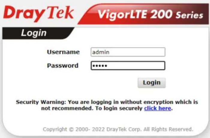
- Open a web browser on your PC and type http://192.168.1.1. The following window will be open to ask for username and password.

text_image
DrayTek VigorLTE 200 Series Login Username admin Password .......... Login Security Warning: You are logging in without encryption which is not recommended. To login securely click here. Copyright © 2000- 2022 DrayTek Corp. All Rights Reserved.- Please type "admin/admin" as the Username/Password and click Login.

Info
If you fail to access to the web configuration, please go to "Trouble Shooting" for detecting and solving your problem.
- Now, the Main Screen will appear. Take VigorLTE 200n as as example.
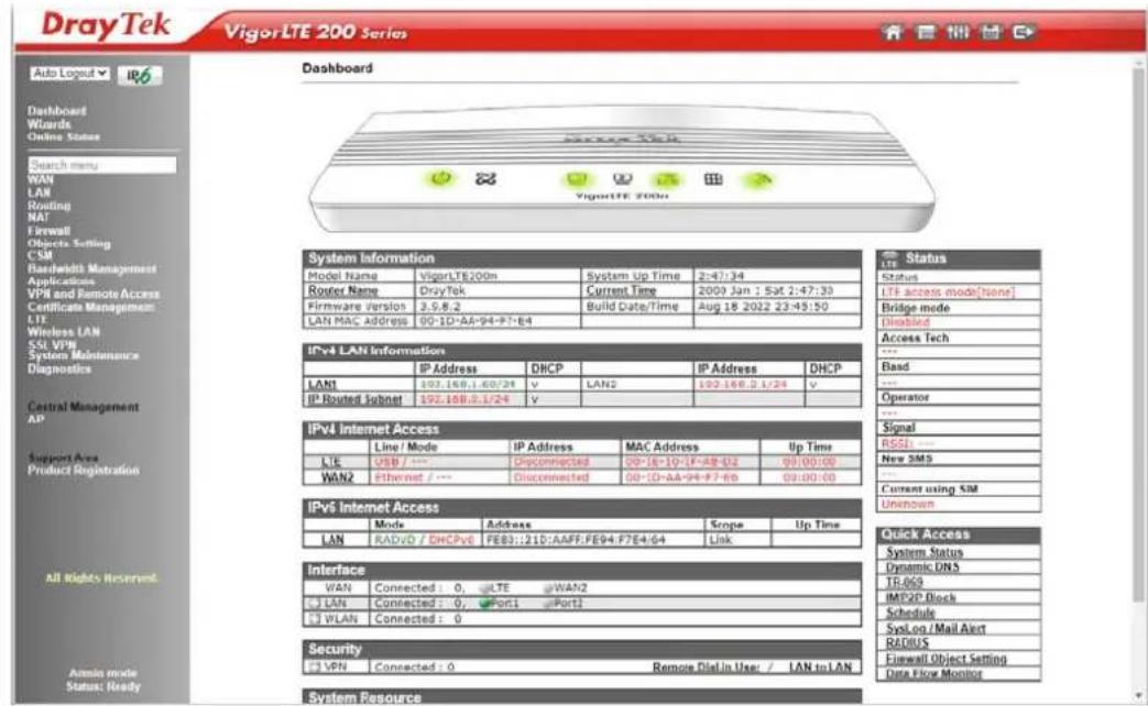
text_image
DrayTek VigorLTE 200 Series Dashboard System Information Model Name VigorLTE200m System Up Time 2:47:34 Router Name DryTek Current Time 2000 Jan 1 Sat 2:47:30 Firmware Version 3.5.8.2 Build Date/Time Aug 18 2022 23:45:50 LAN MAC Address 00-1D-AA-94-F7-E4 IPv4 LAN Information IP Address DHCP IP Address DHCP LAN1 197.16B.1.60/24 V LAN2 192.16B.2.1/24 V IP Routed Subnet 197.16B.3.1/24 V IPv4 Internet Access Line / Mode IP Address MAC Address Up Time USB / --- Disconnected 00-16-10-17-AB-02 00:00:00 WAN2 Ethernet / --- Disconnected 00-1D-AA-94-F7-E6 00:00:00 IPv6 Internet Access Mode Address Scope Up Time LAN RADVO / DHCPv6 FE83::21D:AAFF:FE94:F7E4/64 Link Quick Access System Status Dynamic DNS TR-069 IMP2P Block Schedule SysLog Mail Alert RADIUS Firewall Object Setting Data Flow Monitor System Resource
Info
The home page will be different slightly in accordance with the type of the router you have.
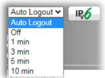
- The web page can be logged out according to the chosen condition. The default setting is Auto Logout, which means the web configuration system will logout after 5 minutes without any operation. Change the setting for your necessity.
text_image
Auto Logout Auto Logout Off 1 min 3 min 5 min 10 minI-4 Changing Password
Please change the password for the original security of the router.
-
Open a web browser on your PC and type http://192.168.1.1. A pop-up window will open to ask for username and password.
-
Please type "admin/admin" as Username/Password for accessing into the web user interface with admin mode.
-
Go to System Maintenance page and choose Administrator Password.
System Maintenance >> Administrator Password Setup
Administrator Password
| Old Password | Max: 23 characters | |
| New Password | (Max. 23 characters allowed) | |
| Confirm Password | (Max. 23 characters allowed) |
Note:
Password can contain only a-z A-Z 0-9, ; :." < > " + = | ? @ # ^ ! ( )
OK
- Enter the login password (the default is "admin") on the field of Old Password. Type New Password and Confirm Password. Then click OK to continue.

Info
The maximum length of the password you can set is 23 characters.
- Now, the password has been changed. Next time, use the new password to access the Web user interface for this router.
text_image
DrayTek VigorLTE 200 Series Login Username admin Password ••••• Login Security Warning: You are logging in without encryption which is not recommended. To login securely click here. Copyright © 2000- 2022 DrayTek Corp. All Rights Reserved.
Info
Even the password is changed, the Username for logging onto the web user interface is still "admin".
I-5 Dashboard
Dashboard shows the connection status including System Information, IPv4 Internet Access, IPv6 Internet Access, Interface (physical connection), Security and Quick Access.
Click Dashboard from the main menu on the left side of the main page.
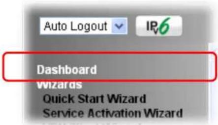
text_image
Auto Logout IP6 Dashboard Wizards Quick Start Wizard Service Activation WizardA web page with default selections will be displayed on the screen. Refer to the following figure:
Dashboard
text_image
ViperLTE VigorLTE 200nSystem Information
| Model Name | VigorLTE200n | System Up Time | 2:47:34 |
| Router Name | DrayTek | Current Time | 2000 Jan 1 Sat 2:47:30 |
| Firmware Version | 3.9.8.2 | Build Date/Time | Aug 18 2022 23:45:50 |
| LAN MAC Address | 00-1D-AA-94-F7-E4 |
IPv4 LAN Information
| IP Address | DHCP | IP Address | DHCP | ||
| LAN1 | 192.168.1.60/24 | v | LAN2 | 192.168.2.1/24 | v |
| IP Routed Subnet | 192.168.0.1/24 | v |
IPv4 Internet Access
| Line / Mode | IP Address | MAC Address | Up Time | |
| LTE | USB / --- | Disconnected | 00-1E-10-1F-AB-D2 | 00:00:00 |
| WAN2 | Ethernet / --- | Disconnected | 00-1D-AA-94-F7-E6 | 00:00:00 |
IPv6 Internet Access
| Mode | Address | Scope | Up Time | |
| LAN | RADVD / DHCPv6 | FE80::21D:AAFF:FE94:F7E4/64 | Link |
Interface
| WAN | Connected : 0, LTE WAN2 |
| LAN | Connected : 0, Port1 Port2 |
| WLAN | Connected : 0 |
Security
| VPN | Connected : 0 | Remote Dial-in User / LAN to LAN |
System Resource
Status
| Status |
| LTE access mode[None] |
| Bridge mode |
| Disabled |
| Access Tech |
| --- |
| Band |
| --- |
| Operator |
| --- |
| Signal |
| RSSI: --- |
| New SMS |
| --- |
| Current using SIM |
| Unknown |
Quick Access
| System Status |
| Dynamic DNS |
| TR-069 |
| IM/P2P Block |
| Schedule |
| SysLog / Mail Alert |
| RADIUS |
| Firewall Object Setting |
| Data Flow Monitor |
I-5-1 Virtual Panel
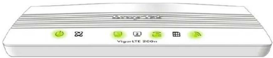
On the top of the Dashboard, a virtual panel (simulating the physical panel of the router) displays the physical interface connection. It will be refreshed every five seconds. When you move and click the mouse cursor on LEDs (except ACT), USB ports, or LAN1 - LAN4, related web setting page will be open for you to configure if required.

text_image
VigorLTE 200n| Port Color | Description | |
| Black It means the router or the function is not working. LED | ||
| Green It means the router or the function is working. | ||
For detailed information about the LED display, refer to I-1-1 LED Indicators and Connectors.
I-5-2 Name with a Link
A name with a link (e.g., Router Name, Current Time, LTE and etc.) below means you can click it to open the configuration page for modification.
| System Information | |||
| Model Name | VigorLTE200n | System-Up Time | 2:49:36 |
| Router Name | DrayTek | Current Time | 2000 Jan 1 Sat 2:49:32 |
| Firmware Version | 3.9.8.2 | Build Date/Time | Aug 18 2022 23:45:50 |
| LAN MAC Address | 00-1D-AA-94-F7-E4 | ||
| IPv4 LAN Information | |||||
| IP Address | DHCP | IP Address | DHCP | ||
| LAN1 | 192.168.1.60/24 | v | LAN2 | 192.168.2.1/24 | v |
| IP Routed Subnet | 192.168.0.1/24 | v | |||
| IPv4 Internet Access | ||||
| Line / Mode | IP Address | MAC Address | Up Time | |
| LTE | USB / --- | Disconnected | 00-1E-10-1F-AB-D2 | 00:00:00 |
| WAN2 | Ethernet / --- | Disconnected | 00-1D-AA-94-F7-E6 | 00:00:00 |
| IPv6 Internet Access | ||||
| Mode | Address | Scope | Up Time | |
| LAN | RADVD / DHCPv6 | FE80::21D:AAFF:FE94:F7E4/64 | Link | |
| Interface | |||
| WAN | Connected : 0, | LTE | WAN2 |
| LAN | Connected : 0, | Port1 | Port2 |
| WLAN | Connected : 0 | ||
| Security | |||
| VPN | Connected : 0 | Remote Dial-in User / LAN to LAN | |
I-5-3 Quick Access for Common Used Menu
All the menu items can be accessed and arranged orderly on the left side of the main page for your request. However, some important and common used menu items which can be accessed in a quick way just for convenience.
Look at the right side of the Dashboard. You will find a group of common used functions grouped under Quick Access.
| Quick Access |
| System Status |
| Dynamic DNS |
| TR-069 |
| IM/P2P Block |
| Schedule |
| SysLog / Mail Alert |
| RADIUS |
| Firewall Object Setting |
| Data Flow Monitor |
The function links of System Status, Dynamic DDNS, TR-069, IM/ P2P Block, Schedule, Syslog/ Mail Alert, RADIUS, Firewall Object Setting and Data Flow Monitor are displayed here. Move your mouse cursor on any one of the links and click on it. The corresponding setting page will be open immediately.
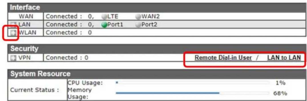
In addition, quick access for VPN security settings such as Remote Dial-in User and LAN to LAN are located on the bottom of this page. Scroll down the page to find them and use them if required.
text_image
Interface WAN Connected : 0, LTE WAN2 LAN Connected : 0, Port1 Port2 WLAN Connected : 0 Security VPN Connected : 0 Remote Dial-in User / LAN to LAN System Resource Current Status : CPU Usage: 1% Memory 68% Usage:Note that there is a plus ( ) icon located on the left side of LAN/ WLAN. Click it to review the LAN/ WLAN connection(s) used presently.
Host connected physically to the router via LAN port(s) will be displayed with green circles in the field of Connected.
All of the hosts (including wireless clients) displayed with Host ID, IP Address and MAC address indicates that the traffic would be transmitted through LAN port(s) and then the WAN port. The purpose is to perform the traffic monitor of the host(s).
I-5-4 GUI Map
text_image
GUI MapAll the functions the router supports are listed with table clearly in this page. Users can click the function link to access into the setting page of the function for detailed configuration. Click the icon on the top of the main screen to display all the functions.
GUI Map
| Wizards | Certificate Management | ||
| Quick Start WizardService Activation WizardVPN Client WizardVPN Server WizardWireless Wizard | LTE | Local CertificateTrusted CA CertificateCertificate Backup | |
| Online Status | General SettingsSMS InboxSend SMSSMS Gateway | ||
| Physical ConnectionVirtual WAN | |||
| WAN | Router CommandsStatus | ||
| General SetupInternet AccessMulti-PVC/VLANWAN budget | Wireless LAN | General SetupSecurityAccess ControlWPSWDSAdvanced SettingAP Discovery | |
| LAN | |||
| General SetupVLANBind IP to MAC | |||
| Routing | Station List | ||
| Static RouteRoute PolicyBGP | SSL VPN | General SetupUser Account | |
| NAT | |||
I-5-5 Web Console
text_image
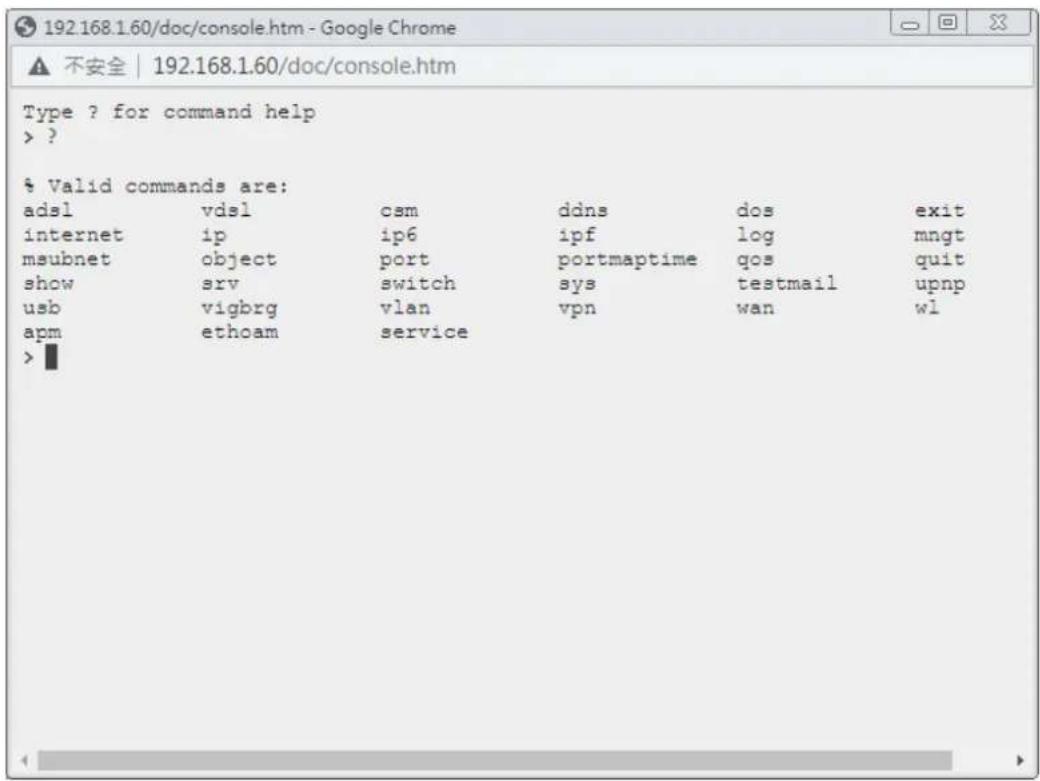
Web ConsoleIt is not necessary to use the telnet command via DOS prompt. The changes made by using web console have the same effects as modified through web user interface. The functions/settings modified under Web Console also can be reviewed on the web user interface.
Click the Web Console icon on the top of the main screen to open the following screen.
text_image
192.168.1.60/doc/console.htm - Google Chrome ▲ 不安全 | 192.168.1.60/doc/console.htm Type ? for command help > ? % Valid commands are: adsl vds1 csm ddns dos exit internet ip ip6 ipf log mngt msubnet object port portmaptime qos quit show srv switch sys testmail upnp usb vigbrg vlan vpn wan wl apm ethoam service >I-5-6 Config Backup
text_image
Config BackupThere is one way to store current used settings quickly by clicking the Config Backup icon. It allows you to backup current settings as a file. Such configuration file can be restored by using System Maintenance>>Configuration Backup.
Simply click the icon on the top of the main screen and a pop up dialog will appear.
Click Save to store the setting.
I-5-7 Logout
text_image
LogoutClick this icon to exit the web user interface.
I-5-8 Online Status
Online Status
Physical Connection
Virtual WAN
I-5-8-1 Physical Connection
Such page displays the physical connection status such as LAN connection status, WAN connection status, ADSL information, and so on.
Physical Connection for IPv4 Protocol
Online Status
| Physical Connection | System Uptime: 0day 3:3:1 | ||||
| IPv4 | IPv6 | ||||
| LAN Status | |||||
| IP Address | TX Packets | RX Packets | Router Primary DNS: | Router Secondary DNS: | |
| 192.168.1.60 | 16,943 | 10,713 | 8.8.8.8 | 8.8.4.4 | |
| LTE Status (Using Unknown) | |||||
| Enable | Line | Name | Mode | Up Time | Signal |
| Yes | USB | --- | 00:00:00 | - | |
| IP | GW IP | TX Packets | TX Rate(bps) | RX Packets | RX Rate(bps) |
| --- | --- | 0 | 0 | 0 | 0 |
| WAN 2 Status | |||||
| Enable | Line | Name | Mode | Up Time | |
| No | Ethernet | --- | 00:00:00 | ||
| IP | GW IP | TX Packets | TX Rate(bps) | RX Packets | RX Rate(bps) |
| --- | --- | 0 | 0 | 0 | 0 |
Physical Connection for IPv6 Protocol
Online Status
| Physical Connection | System Uptime: 0day 3:3:39 | |||
| IPv4 | IPv6 | |||
| LAN Status | ||||
| IP Address | ||||
| FE80::21D:AAFF:FE94:F7E4/64 (Link) | ||||
| TX Packets | RX Packets | TX Bytes | RX Bytes | |
| 53 | 46 | 4,142 | 3,588 | |
| LTE IPv6 Status | ||||
| Enable | Mode | Up Time | ||
| No | Offline | --- | ||
| IP | Gateway IP | |||
| --- | --- | |||
| WAN2 IPv6 Status | ||||
| Enable | Mode | Up Time | ||
| No | Offline | --- | ||
| IP | Gateway IP | |||
| --- | --- | |||
Detailed explanation (for IPv4) is shown below:
| Item | Description |
| LAN Status IP Address-Displays the IP address of the LAN interface.TX Packets-Displays the total transmitted packets at the LAN interface.RX Packets-Displays the total received packets at the LAN interface. | |
| LTE Status / WAN2 Status | Enable - Yes in red means such interface is available but not enabled. Yes in green means such interface is enabled.Line - Displays the physical connection of this interface.Name - Display the name of the router.Mode - Displays the type of WAN connection (e.g., PPPoE).Up Time - Displays the total uptime of the interface.IP - Displays the IP address of the WAN interface.GW IP - Displays the IP address of the default gateway.TX Packets - Displays the total transmitted packets at the WAN interface.TX Rate - Displays the speed of transmitted octets at the WAN interface.RX Packets - Displays the total number of received packets at the WAN interface.RX Rate - Displays the speed of received octets at the WAN interface. |
Detailed explanation (for IPv6) is shown below:
| Item | Description |
| LAN Status | IP Address- Displays the IPv6 address of the LAN interface..TX Packets-Displays the total transmitted packets at the LANinterface.RX Packets-Displays the total received packets at the LAN interface.TX Bytes - Displays the speed of transmitted octets at the LAN interface.RX Bytes - Displays the speed of received octets at the LAN interface. |
| LTE / WAN IPv6 Status Enable - No in red means such interface is available but not enabled. Yes in green means such interface is enabled. No in red means such interface is not available.Mode - Displays the type of WAN connection (e.g., TSPC).Up Time - Displays the total uptime of the interface.IP - Displays the IP address of the WAN interface.Gateway IP - Displays the IP address of the default gateway. | |

Info
The words in green mean that the WAN connection of that interface is ready for accessing Internet; the words in red mean that the WAN connection of that interface is not ready for accessing Internet.
I-5-8-2 Virtual WAN
Such page displays the virtual WAN connection information.
Virtual WAN are used by TR-069 management, and so on.
The field of Application will list the purpose of such WAN connection.
Online Status
| Virtual WAN | System Uptime: 0day 3:4:31 | ||||
| WAN 5 Status | |||||
| Enable | Line | Name | Mode | Up Time | Application |
| No | ADSL | --- | 00:00:00 | ||
| IP | GW IP | TX Packets | TX Rate(bps) | RX Packets | RX Rate(bps) |
| --- | --- | 0 | 0 | 0 | 0 |
| WAN 6 Status | |||||
| Enable | Line | Name | Mode | Up Time | Application |
| No | ADSL | --- | 00:00:00 | ||
| IP | GW IP | TX Packets | TX Rate(bps) | RX Packets | RX Rate(bps) |
| --- | --- | 0 | 0 | 0 | 0 |
| WAN 7 Status | |||||
| Enable | Line | Name | Mode | Up Time | Application |
| No | ADSL | --- | 00:00:00 | ||
| IP | GW IP | TX Packets | TX Rate(bps) | RX Packets | RX Rate(bps) |
| --- | --- | 0 | 0 | 0 | 0 |
I-6 Quick Start Wizard
Quick Start Wizard can help you to deploy and use the router easily and quickly. Go to Wizards>>Quick Start Wizard. The first screen of Quick Start Wizard is entering login password. After typing the password, please click Next.
Quick Start Wizard
Enter login password
Please enter an alpha-numeric string as your Password.
Old Password
New Password
Confirm Password
Max 23 characters
Hint: If you want to keep the password unchanged, leave the password blank and press "Next" button to skip this process.
< Back
Next >
Finish
Cancel
On the next page, please select the WAN interface that you use. If WAN interface is used, please choose WAN1; if USB interface is used, please choose LTE. Then click Next for next step. WAN2 and LTE will bring up different configuration page. Here, we take LTE as an example.
Quick Start Wizard
WAN Interface
WAN Interface:
Display Name:
Physical Mode:
LTE
USB
< Back
Next>
Finish
Cancel
I-6-1 LTE
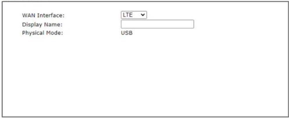
- Choose LTE. Enter a string as Display Name (optional). Click Next.
Quick Start Wizard
WAN Interface
text_image
WAN Interface: Display Name: Physical Mode: LTE USB
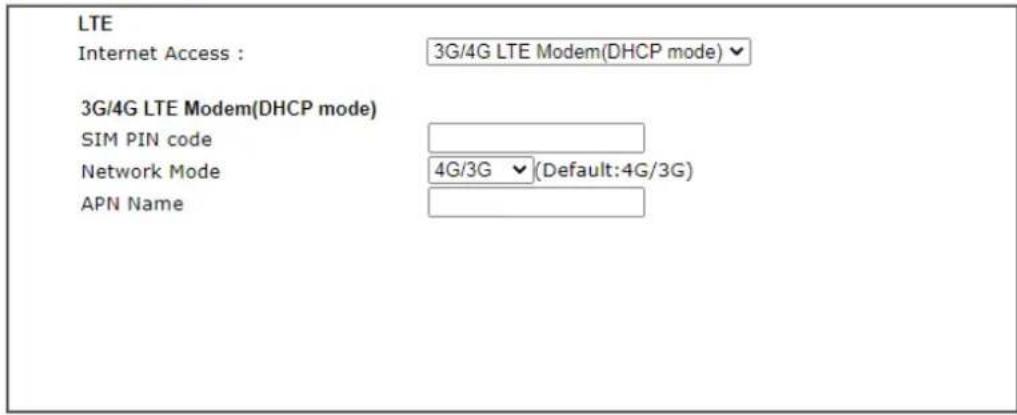
- After clicking Next, you will get the following web page.
Quick Start Wizard
Connect to Internet
text_image
LTE Internet Access : 3G/4G LTE Modem(DHCP mode) 3G/4G LTE Modem(DHCP mode) SIM PIN code Network Mode 4G/3G (Default:4G/3G) APN Name
Available settings are explained as follows:
| Item | Description |
| Internet Access Specify a connection mode from the drop down menu. | |
| SIM PIN code | Enter PIN code of the SIM card that will be used to access Internet. |
| Network Mode | Force Vigor router to connect Internet with the mode specified here. If you choose 4G/ 3G/ 2G as network mode, the router will choose a suitable one according to the actual wireless signal automatically. |
| APN Name APN means | Access Point Name which is provided and required by some ISPs. |
| Back Click it to return | to previous setting page. |
| Next Click it to get into the next setting page. | |
| Cancel Click it to give up the quick start wizard. | |
- Please manually enter the Username/ Password provided by your ISP. Click Next for viewing summary of such connection.
Quick Start Wizard
Please confirm your settings:
WAN Interface:
LTE
Physical Mode:
USB
Internet Access:
DHCP
Click Back to modify changes if necessary. Otherwise, click Finish to save the current settings and restart the Vigor router.

- Click Finish. A page of Quick Start Wizard Setup OK!!! will appear.
Quick Start Wizard Setup OK!
- Now, you can enjoy surfing on the Internet.
I-6-2 WAN2 (Ethernet)
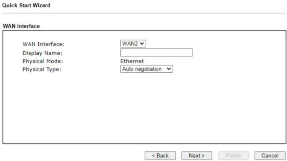
WAN2 can be configured for physical mode of Ethernet. If you choose Ethernet WAN2, please specify a physical type. Then, click Next.
text_image
Quick Start Wizard WAN Interface WAN Interface: WAN2 Display Name: Physical Mode: Ethernet Physical Type: Auto negotiation < Back Next > Finish CancelAvailable settings are explained as follows:
| Item | Description |
| Display Name Type a name for the router. | |
| Physical Mode Display the physical mode of this WAN interface. | |
| Physical Type | This setting is available when Ethernet is selected as Physical Mode. In general, Auto negotiation is suggested. |
PPPoE
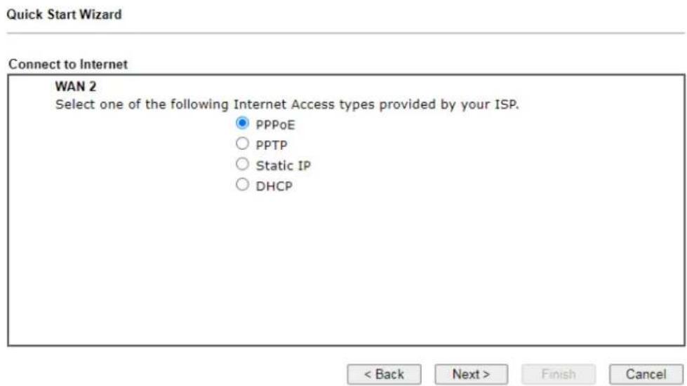
- Choose WAN2 as the WAN Interface and choose Ethernet as the Physical Mode. Click the Next button. The following page will be open for you to specify Internet Access Type.
text_image
Quick Start Wizard Connect to Internet WAN 2 Select one of the following Internet Access types provided by your ISP. ● PPPoE ○ PPTP ○ Static IP ○ DHCP < Back Next > Finish Cancel- Click PPPoE as the Internet Access Type. Then click Next to get the following page.
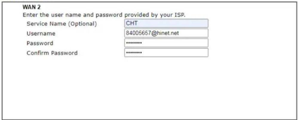
PPPoE Client Mode
text_image
WAN 2 Enter the user name and password provided by your ISP. Service Name (Optional) CHT Username 84005657@hinet.net Password .......... Confirm Password ..........
Available settings are explained as follows:
| Item | Description |
| Service Name(Optional) | Enter the description of the specific network service. |
| Username Assign a sp | specific valid user name provided by the ISP.Note: The maximum length of the user name you can set is 63 characters. |
| Password Assign a val | id password provided by the ISP.Note: The maximum length of the password you can set is 62 characters. |
| Confirm Password Re | Enter the password. |
| Back Click it to return | to previous setting page. |
| Next Click it to get into | to the next setting page. |
| Cancel Click it to give up | the quick start wizard. |
- Please manually enter the Username/ Password provided by your ISP. Click Next for viewing summary of such connection.
Quick Start Wizard
Please confirm your settings:
| WAN Interface: | WAN2 |
| Physical Mode: | Ethernet |
| Physical Type: | Auto negotiation |
| Internet Access: | PPPoE |
Click Back to modify changes if necessary. Otherwise, click Finish to save the current settings and restart the Vigor router.

- Click Finish. A page of Quick Start Wizard Setup OK!!! will appear.
Quick Start Wizard Setup OK!
- Now, you can enjoy surfing on the Internet.
PPTP
- Choose PPTP as the WAN Interface and click the Next button.
Quick Start Wizard
Connect to Internet
WAN 2
Select one of the following Internet Access types provided by your ISP.
- The following page will be open for you to Enter all the information originally provided by your ISP.
Quick Start Wizard
PPTP Client Mode
WAN 2
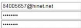
Enter the username, password, WAN IP configuration and PPTP server IP provided by your ISP.
Username
Password
Confirm Password
WAN IP Configuration
○ Obtain an IP address automatically
Specify an IP address
IP Address
Subnet Mask
Gateway
Primary DNS
Second DNS
PPTP Server
| 8.8.8.8 |
| 8.8.4.4 |

Available settings are explained as follows:
| Item | Description |
| Username Assign a specific valid user name provided by the ISP.Note: The maximum length of the user name you can set is 63 characters. | |
| Password Assign a valid password provided by the ISP.Note: The maximum length of the password you can set is 62 characters. | |
| Confirm Password ReEnter the password. | |
| WAN IP Configuration | Obtain an IP address automatically - the router will get anIP address automatically from DHCP server.Specify an IP address - you have to type relational settings manually.IP Address - Enter the IP address.Subnet Mask -Enter the subnet mask.Gateway - Enter the IP address of the gateway.Primary DNS - Enter the primary IP address for the router.Secondary DNS - Enter the secondary IP address for necessity in the future. |
| PPTP Server Enter the IP address of the server. | |
| Back Click it to return to previous setting page. | |
| Next Click it to get into the next setting page. | |
| Cancel Click it to give up the quick start wizard. | |
- Please Enter the IP address/ mask/ gateway information originally provided by your ISP. Then click Next for viewing summary of such connection.
Quick Start Wizard
Please confirm your settings:
WAN Interface:
WAN2
Physical Mode:
Ethernet
Physical Type:
Auto negotiation
Internet Access:
PPTP
Click Back to modify changes if necessary. Otherwise, click Finish to save the current settings and restart the Vigor router.

- Click Finish. A page of Quick Start Wizard Setup OK!!! will appear. Then, the system status of this protocol will be shown.
Quick Start Wizard Setup OK!
- Now, you can enjoy surfing on the Internet.
Static IP
- Click Static IP as the Internet Access type and click the Next button.
Quick Start Wizard
Connect to Internet
WAN 2
Select one of the following Internet Access types provided by your ISP.
○ PPPoE
○ PPTP
Static IP
DHCP

- The following page will be open for you to Enter the IP address information originally provided by your ISP.
Quick Start Wizard
Static IP Client Mode
WAN 2
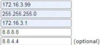
Enter the Static IP configuration provided by your ISP.
WAN IP
Subnet Mask
Gateway
Primary DNS
Secondary DNS
text_image
172.16.3.99 255.255.255.0 172.16.3.1 8.8.8.8 8.8.4.4 (optional)
Available settings are explained as follows:
| Item | Description |
| WAN IP Enter the IP address. | |
| Subnet Mask Enter the subnet mask. | |
| Gateway Enter the IP address of gateway. | |
| Primary DNS Enter the primary IP address for the router. | |
| Secondary DNS Enter secondary IP address for necessity in the future. | |
| Back Click it to return to previous setting page. | |
| Next Click it to get into the next setting page. | |
| Cancel Click it to give up the quick start wizard. | |
- Click Next for next step.
Quick Start Wizard
Please confirm your settings:
WAN Interface:
WAN1
Physical Mode:
Ethernet
Physical Type:
Auto negotiation
Internet Access:
Static IP
Click Back to modify changes if necessary. Otherwise, click Finish to save the current settings and restart the Vigor router.

- Click Finish. A page of Quick Start Wizard Setup OK!!! will appear.
Quick Start Wizard Setup OK!
- Now, you can enjoy surfing on the Internet.
DHCP
- Click DHCP as the Internet Access type and click the Next button.
Quick Start Wizard
Connect to Internet
WAN 2
Select one of the following Internet Access types provided by your ISP.
- The following page will be open for you to Enter the IP address information originally provided by your ISP.
Quick Start Wizard
DHCP Client Mode
WAN 2
If your ISP requires you to enter a specific host name or specific MAC address, please enter it in.
Host Name
MAC


Available settings are explained as follows:
| Item | Description |
| Host Name Enter the name of the host. | Note: The maximum length of the host name you can set is 39 characters. |
| MAC Some Cable service providers specify a specific MAC address for access authentication. In such cases you need to enter the MAC address. | |
| Back Click it to return to previous setting page. | |
| Next Click it to get into the next setting page. | |
| Cancel Click it to give up the quick start wizard. | |
- After finished the settings above, click Next for viewing summary of such connection.
Quick Start Wizard
Please confirm your settings:
WAN Interface:
WAN2
Physical Mode:
Ethernet
Physical Type:
Auto negotiation
Internet Access:
DHCP
Click Back to modify changes if necessary. Otherwise, click Finish to save the current settings and restart the Vigor router.

- Click Finish. A page of Quick Start Wizard Setup OK!!! will appear. Then, the system status of this protocol will be shown.
Quick Start Wizard Setup OK!
- Now, you can enjoy surfing on the Internet.
I-7 Service Activation Wizard
Service Activation Wizard can guide you to activate WCF service (Web Content Filter) with a quick and easy way. For the Service Activation Wizard is only available for admin operation, please type "admin/admin" on Username/Password while Logging into the web user interface.
Service Activation Wizard is a tool which allows you to activate services without accessing into the server (MyVigor) located on http://myvigor.draytek.com.

Info
Such function is available only for Admin Mode.
1. Open Wizards>>Service Activation Wizard.
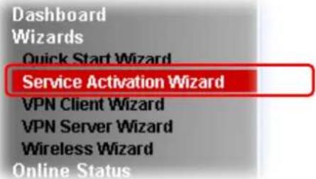
text_image
Dashboard Wizards Quick Start Wizard Service Activation Wizard VPN Client Wizard VPN Server Wizard Wireless Wizard Online Status- In the following page, you can activate the Web content filter services and DNS service at the same time or individually. When you finish the selection, please click Next.
Service Activation Wizard
Select the service type that you want to activate
Activation Date : 2019-02-25
Web Content Filter(WCF) Service :
BPJM
License Agreement
This is a web content filter that is provided by the German government. It is a free service without any guarantee and will expire one year after activation. You may re-activate the service after expiry.
√ Cren 30-Days Free Trial
License Agreement
This is a worldwide web content filter service. The free trail license can only be used once. At the end of the free trail period you may purchase the official one-year Cyren Web Content Filter from an authorized DrayTek reseller.
Dynamic DNS(DDNS) Service :
DT-DDNS
License Agreement
This is a Dynamic Domain Name Service that is provided by DrayTek company. It is a free service will expire 1 year after activation.
You may re-active the service after expiry.
Domain Name: 2017101210301001 .drayddns.com
I have read and accept the above Agreement. (Please check this box).

Info
BPjM is web content filter (WCF) for German Speaking users. It is ideal for your family to provide more Internet security for youngsters.
Cryan 30-day trial is WCF which offers 30-day trial period. After trial, you can purchase DrayTek's prepared Cryan GlobalView WCF package from retailing outlets.
DT-DDNS, developed by DrayTek, offers one year free charge service of dynamic DNS service for internal use.
- Setting confirmation page will be displayed as follows, please click Activate.
Service Activation Wizard
Please confirm your settings
Sevice Type : Trial version
Sevice Activated : Web Content Filter ( Cyren / Commtouch )
Dynamic DNS (2017101210301001.drayddns.com)
Please click Back to re-select service type you to activate.


Info
The service will be activated and applied as the default rule configured in Firewall>>General Setup.
- Now, the web page will display the service that you have activated according to your selection(s). The valid time for the free trial of these services is one month.
Service Activation Wizard
Please confirm your settings
DrayTek Service Activation
| Service Name | Start Date | Expire Date | Status |
| Web Content filter | 2019-02-25 | 2019-03-25 | Cyren |
| DDNS | 2019-02-25 | 2019-03-25 | DT-DDNS |
Please check if the license fits with the service provider of your signature. To ensure normal operation for your router, update your signature again is recommended.
Copyright © DrayTek Corp. All Rights Reserved.

I-8 Registering Vigor Router
You have finished the configuration of Quick Start Wizard and you can surf the Internet at any time. Now it is the time to register your Vigor router to MyVigor website for getting more service. Please follow the steps below to finish the router registration.
1 Please login the web configuration interface of Vigor router by typing "admin/admin" as User Name / Password.
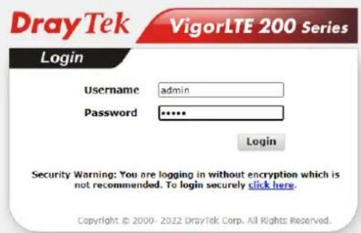
text_image
DrayTek VigorLTE 200 Series Login Username admin Password ***** Login Security Warning: You are logging in without encryption which is not recommended. To login securely click here. Copyright © 2000- 2022 DrayTek Corp. All Rights Reserved.2 Click Support Area>>Production Registration from the home page.
Support Area Product Registration
3 A Login page will be shown on the screen. Please Enter the account and password that you created previously. And click Login.
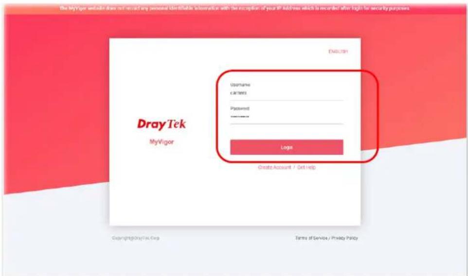
text_image
The MyVigor website does not recall any personal identity information with the exception of your IP address which is recorded when login for security purposes. ENGLISH Username callants Password ****** Login Create Account / Get Help Dray Tek MyVigor Copyright@DrayTek Corp Terms of Service / Privacy Policy
Info
If you haven't an accessing account, please refer to section Creating an Account for MyVigor to create your own one. Please read the articles on the Agreement regarding user rights carefully while creating a user account.
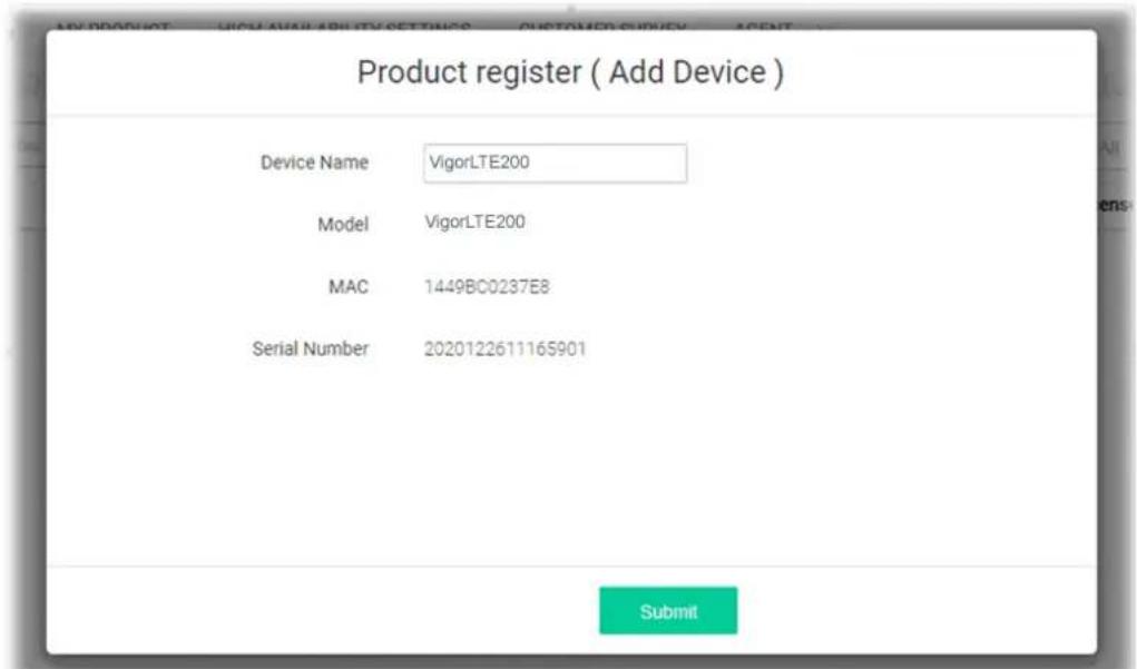
4 The following page will be displayed after you logging in MyVigor. Type a nickname for the router, then click Submit.
text_image
Product register ( Add Device ) Device Name VigorLTE200 Model VigorLTE200 MAC 1449BC0237E8 Serial Number 202012261116S901 Submit5 When the following page appears, your router information has been added to the database. Your router has been registered to myvigor website successfully.
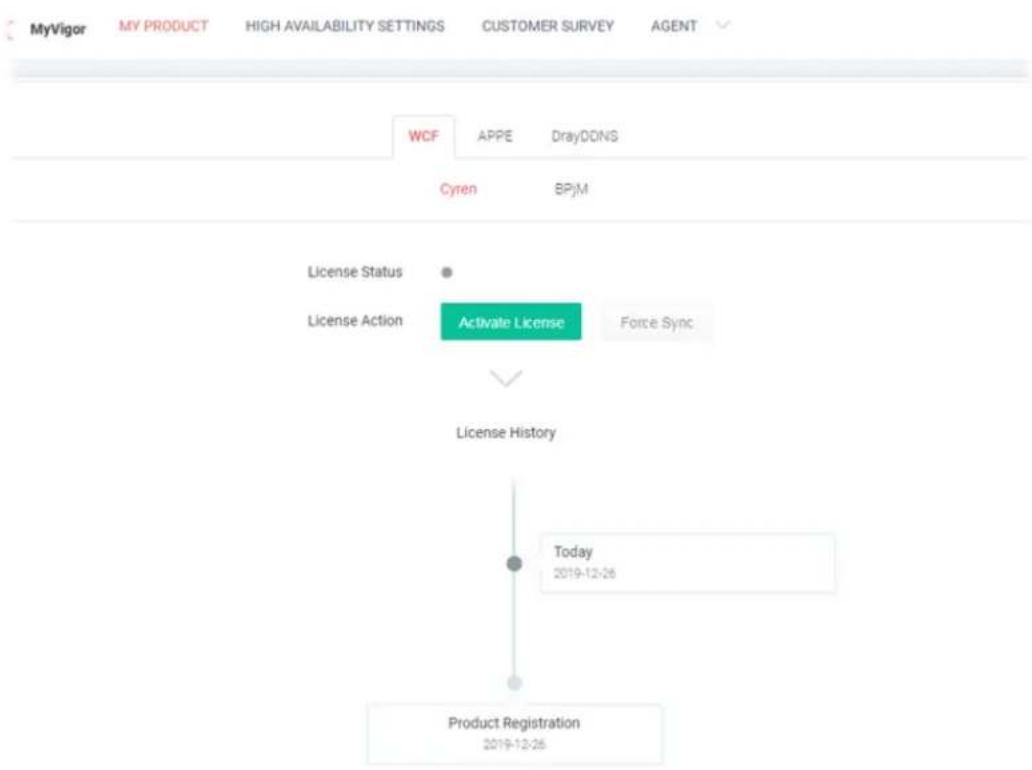
flowchart
graph TD
    A["License Status"] --> B["License Action"]
    B --> C["Activate License"]
    C --> D["Force Sync"]
    D --> E["License History"]
    E --> F["Today 2019-12-26"]
    F --> G["Product Registration 2019-12-26"]
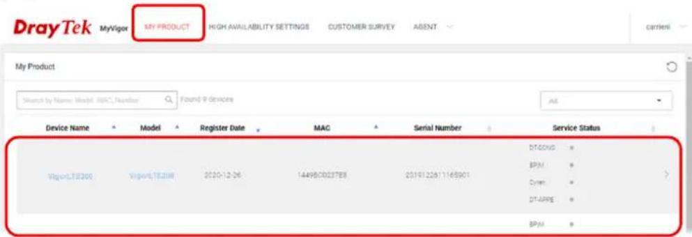
6 Clicking MY PRODUCT for viewing the general information of the registered router on MyVigor website.
text_image
DrayTek MyVigor MY PRODUCT HIGH AVAILABILITY SETTINGS CUSTOMER SURVEY AGENT My Product Search by Name: Model: MRC Number Found P devices Device Name Model Register Date MAC Serial Number Service Status Vigori.TE200 Vigori.TE20M 2020-12-26 1449BC0237EB 2019122811165901 DT-GND BPM Cmm DT-APPE BPMThis page is left blank.
Part II Connectivity

WAN

LAN

NAT

Applications

Routing
It means wide area network. Public IP will be used in WAN.
It means local area network. Private IP will be used in LAN. Local Area Network (LAN) is a group of subnets regulated and ruled by router. The design of network structure is related to what type of public IP addresses coming from your ISP.
When the data flow passing through, the Network Address Translation (NAT) function of the router will dedicate to translate public/private addresses, and the packets will be delivered to the correct host PC in the local area network.
DNS, LAN DNS, IGMP, UPnP, WOL, RADIUS, SMS.
Static Route
II-1 LTE
LTE WAN with SIM card can provide convenient Internet access for Vigor router. However, we can't stop thinking about what can Vigor router utilize this SIM card to provide more useful functions for user? Now, we have developed some useful functions for user, such as sending SMS from a router to report router status, rebooting router remotely via SMS with taking security into consideration, and so on.
This section can guide you to use the SIM card in LTE WAN to perform SMS related operations.
Service Network
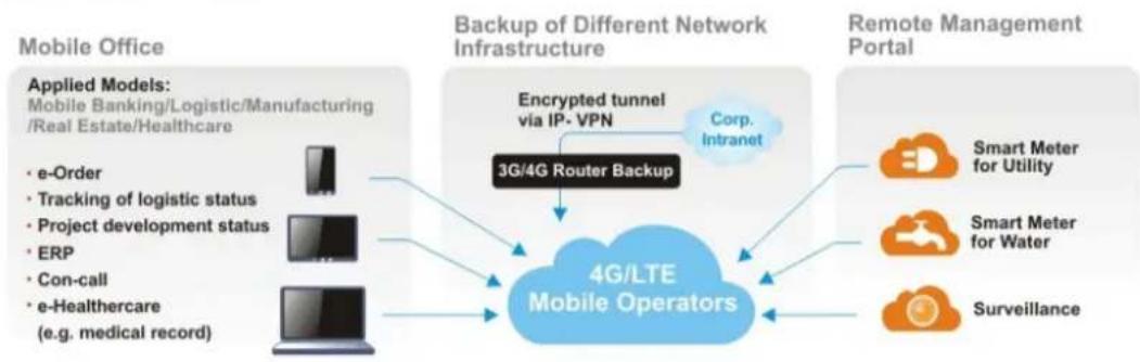
flowchart
graph TD
    A["Applied Models: Mobile Banking/Logistic/Manufacturing /Real Estate/Healthcare"] --> B["• e-Order"]
    A --> C["• Tracking of logistic status"]
    A --> D["• Project development status"]
    A --> E["• ERP"]
    A --> F["• Con-call"]
    A --> G["• e-Healthcare (e.g. medical record)"]
    H["Mobile Office"] --> I["Backup of Different Network Infrastructure"]
    I --> J["3G/4G Router Backup"]
    J --> K["4G/LTE Mobile Operators"]
    K --> L["Encrypted tunnel via IP-VPN"]
    L --> M["Corp. Intranet"]
    K --> N["Remote Management Portal"]
    K --> O["Smart Meter for Utility"]
    K --> P["Smart Meter for Water"]
    K --> Q["Surveillance"]
Web User Interface
LTE
General Settings
SMS Inbox
Send SMS
SMS Gateway
Router Commands
Status
II-1-1 General Settings
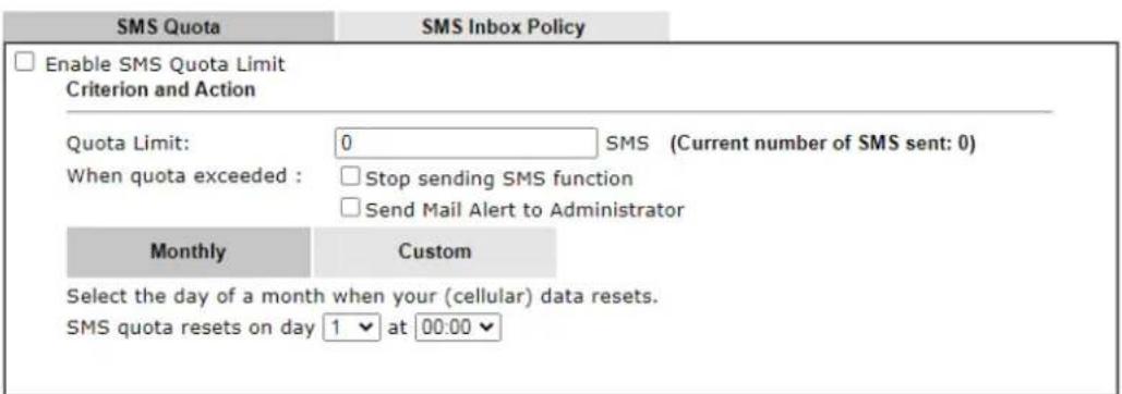
This page allows you to configure general settings for LTE. When SMS Quota Limit is enabled, you can specify the number of SMS quota, actions to perform when quota exceeded, and the period of resetting SMS quota used.
II-1 -1-1 SMS Quota
LTE >> General Settings
text_image
SMS Quota Enable SMS Quota Limit Criterion and Action Quota Limit: 0 SMS (Current number of SMS sent: 0) When quota exceeded : □ Stop sending SMS function □ Send Mail Alert to Administrator Monthly Custom Select the day of a month when your (cellular) data resets. SMS quota resets on day 1 ▼ at 00:00 ▼Note: 1. Please make sure the Time and Date of the router is configured.
- When quota exceeded, user can choose to stop sending sms or send e-mail to administrator.
- After clicking OK, the counter used will be reset.
OK Cancel
Available settings are explained as follows:
| Item | Description |
| Enable SMS Quota Limit Check the box to enable such feature. | |
| Quota Limit Specify the maximum number of sending SMS for LTE. | |
| When quota exceeded There are two actions to be performed when the quota limit is expired.Stop sending SMS – If it is checked, no SMS for LTE will be sent after the quota limit is expired.Send Mail Alert to Administrator – If it is checked, a mail alert will be sent to the administrator when the quota limit is expired. | |
| Monthly This setting is to offer a mechanism of resetting the number of SMS sent record every month. | |
| SMS quota resets on day XX at XX ... -You can determine the starting day in one month. The number of SMS sent will be reset. | |
| Custom | This setting allows the user to define the billing cycle according to his request.The number of SMS sent will be reset with an interval of cycle duration.Custom- Monthly is default setting. If long period or a short period is required, useCustom. The period of reset is between 1 day and 60 days. You can determine the cycle duration by specifying the days and the hours.Cycle duration: Specify the days to reset the number of SMS sent. For example, 7 means the whole cycle is 7 days; 20 means the whole cycle is 20 days. When the time is up, the router will reset the number of SMS sent automatically.Today is day XX in the cycle-Specify the day in the cycle duration as the starting point which Vigor router will reset the number of SMS sent. For example, 3 means the third day of the duration cycle. |
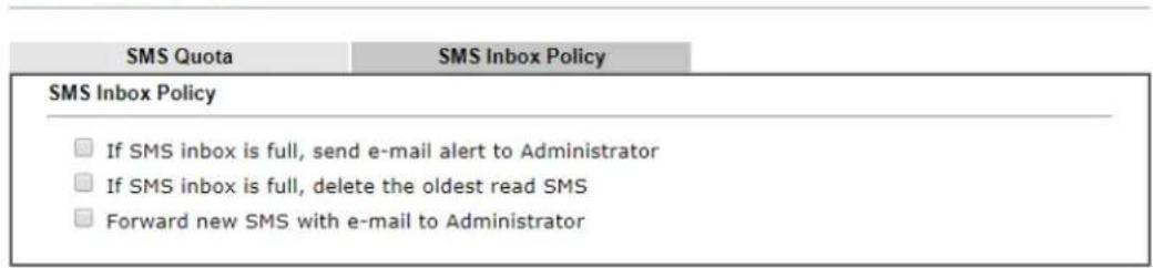
Such page allows you to determine which policy shall be used for SMS inbox/outbox.
LTE >> General Settings
text_image
SMS Quota SMS Inbox Policy SMS Inbox Policy □ If SMS inbox is full, send e-mail alert to Administrator □ If SMS inbox is full, delete the oldest read SMS □ Forward new SMS with e-mail to Administrator
II-1-2 SMS Inbox
This page will list the received SMS messages in the LTE SIM card. The SMS Inbox table shows the received date, the phone number or sender ID where this message was from, and the beginning of the message content.
Since the data size of one SMS is limited, a long message will be sent by multiple SMS. For the convenience of users, we provide two modes. Simple Mode lists SMS messages in order for received time. Advanced Mode lists SMS in order for real index in the SIM card. Different SIM cards have different capacities. In general, it's around 30 to 40 SMS. Please note that the SIM card can not receive new SMS when all SMS indexes are occupied.
Click the Simple Mode link or the Advanced Mode link below to switch between these two modes.
II-1-2-1 Simple Mode
LTE >> SMS Inbox
LTE SMS Inbox
| Details | Mark as Read | Delete | Date | From | Message |
| View | 2015/10/21 12:03:29 | 886911520000 | |||
| View | 2015/10/21 11:31:59 | +886905269930 | 22 | ||
| View | 2015/10/21 11:31:51 | +886905269930 | 11 | ||
| View | 2015/10/21 09:29:39 | +886905269930 | 1 | ||
| View | 2015/10/20 10:15:44 | +886988126053 | remote reboot 000000 | ||
| View | 2015/10/20 10:14:18 | +886988126053 | remote reboot 000000 | ||
| View | 2015/10/20 10:06:49 | +886988126053 | remote reboot iyt | ||
| View | 2015/10/20 10:01:01 | +886905269930 | 41 | ||
| View | 2015/10/16 14:13:29 | +886988126053 | |||
| View | 2015/10/16 14:12:46 | +886988126053 |
Simple Mode: Show SMS messages in order of received dates.
Advanced Mode: Show SMS in order of indexes in SIM card.
OK
Available settings are explained as follows:
| Item | Description |
| Mark as Read Those messages | in "unread" state are showed in bold text. If you want to change messages into "read" state, select them and click the OK button. Checking the checkbox in title will select all "unread" messages in this page. |
| Delete | If you want to delete messages, select them and click the OK button. Checking the checkbox in title will select all messages in this page. |
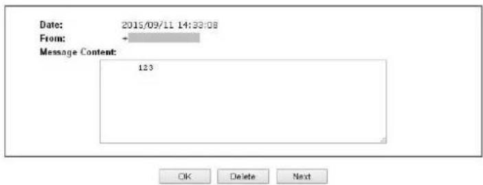
| Details If you want to read the full content of the message, click the View link of that message to open the following page. It will change the message into "read" state. | |
LTE >> SMS Inbox
text_image
Date: 2015/09/11 14:33:08 From: Message Content: 123 OK Delete Next- Message Content - Display the full content of the message.
- OK - Return to previous page.
- Delete - Click it to delete this message and return to previous page.
- Next - Click it to see the content of next message.
II-1-2-1 Advanced Mode
LTE >> SMS Inbox
LTE SMS Inbox
| Index | Mark as Read | Delete | Date | From | Message |
| 1. | 2011/09/08 05:22:56 | + | |||
| 2. | 2015/09/10 13:54:33 | + | |||
| 3. | 2015/09/10 17:27:43 | + | router status 123 | ||
| 4. | 2015/09/10 17:28:37 | + | |||
| 5. | 2015/09/10 18:24:32 | + | router status 123 | ||
| 6. | 2015/09/10 18:25:39 | + | |||
| 7. | 2015/09/10 19:37:44 | + | router status 123 | ||
| 8. | 2015/09/10 19:39:09 | + | 1234567890 | ||
| 9. | 2015/09/10 20:08:46 | + | %^@0%@%&^*$( ) #^! |
Available settings are explained as follows:
| Item | Description |
| Mark as Read Those SMS in " | "unread" state are shown in bold text. If you want to change SMS into "read" state, select them and click the OK button. Checking the checkbox in title will select all "unread" SMS in this page. |
| Delete If you want to delete | SMS, select them and click the OK button. Checking the checkbox in title will select all SMS in this page. |
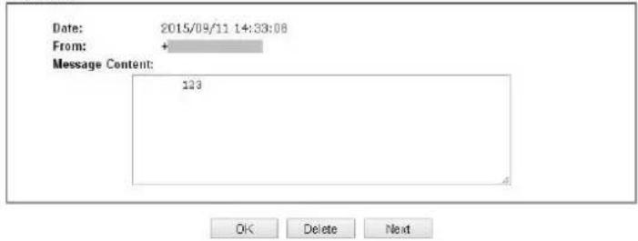
| Index If you want to read the | full content of the message of the SMS, click the index link of that SMS to open the following page. It will change all SMS of the message into "read" state. |
LTE >> SMS Inbox
Index No.17
text_image
Date: 2015/09/11 14:33:08 From: + Message Content: 123 OK Delete NextMessage Content - Display the full content of the message.
OK - Return to previous page.
Delete - Click it to delete all SMS of this message and return to previous page.
Next - Click it to see the content of next SMS index.
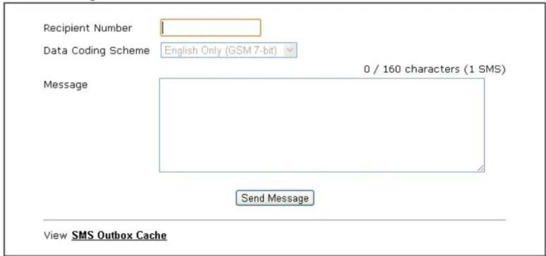
II-1-3 Send SMS
This page is used to send SMS messages by the LTE SIM card. It also displays the number of SMS required to send the message.
LTE >> Send SMS
Send SMS Message
text_image
Recipient Number Data Coding Scheme English Only (GSM 7-bit) Message 0 / 160 characters (1 SMS) Send Message View SMS Outbox CacheAvailable settings are explained as follows:
| Item | Description |
| Recipient Number Type the | phone number of the recipient.The format can be an international phone number(+8869123455678) or a general phone number(0912345678). |
| Data Coding Scheme The router will automatically select a suitable Data Coding Scheme according to the current content in Message. GSM 7-bit and UCS-2 are supported. | |
| Message Type in the message content to send.The total number of characters that you can type in this field is 1024. | |
| Send Message Click it to send this SMS message to the recipient immediately. | |
| View SMS Outbox Cache | Display the record of SMS messages sent from the Router.LTE >> SMS Outbox CacheLTE SMS Outbox CacholDetails Delete Date To MessageView □ 2015/10/05 03:12:06 1234567800 5555555555555555555View □ 2015/10/05 03:12:01 1234567800 9444444444444444View □ 2015/10/05 03:11:56 1234567800 33333333333333333View □ 2015/10/05 03:11:51 1234567800 222222222222View □ 2015/10/05 03:11:46 1234567800 111111View □ 2015/10/05 03:07:55 1234567800 星至科技於1997年成立。View □ 2015/10/05 03:04:38 1234567800 Test Test Nancy 123Note: Records in Outbox Cache are NOT preserved after replacement of newer records or Router reboot.OK |
II-1-4 SMS Gateway
Vigor router can serve as an SMS Gateway for sending alerts via SMS to mobile phones.
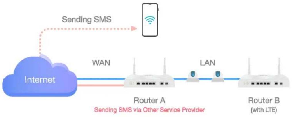
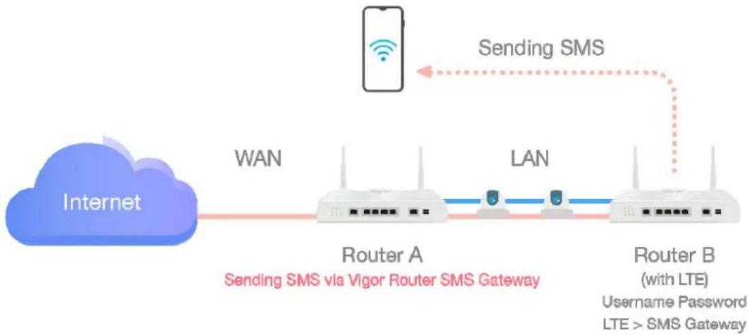
Take a look at the following two pictures.
The IP cameras connect to Router A and Router B via LAN. Where there is something wrong with IP camera, Router A can only send the SMS with alerts/warning message via a specified service provider on Internet.
flowchart
graph LR
    A["Internet"] -->|WAN| B["Router A"]
    B -->|LAN| C["Router B (with LTE)"]
    D["Client"] -->|Sending SMS| E["Mobile Device"]
    style A fill:#800000,stroke:#333
    style B fill:#fff,stroke:#333
    style C fill:#fff,stroke:#333
    style D fill:#fff,stroke:#333
    style E fill:#fff,stroke:#333
With the feature of SMS Gateway on Router B, even Router A is offline, router B could serve as an SMS Gateway that can send SMS (related to alerts or other events) to mobile phones directly.
flowchart
graph LR
    A["Internet"] -->|WAN| B["Router A"]
    B -->|LAN| C["Router B (with LTE)"]
    C -->|Sending SMS| D["Mobile Phone"]
    style A fill:#99CCFF,stroke:#333
    style B fill:#99CCFF,stroke:#333
    style C fill:#99CCFF,stroke:#333
    style D fill:#FF9900,stroke:#333
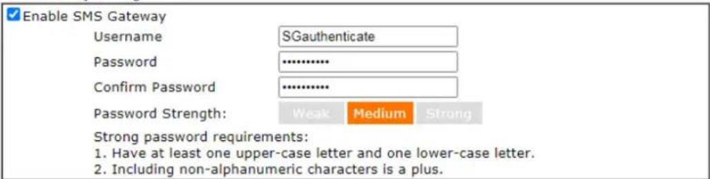
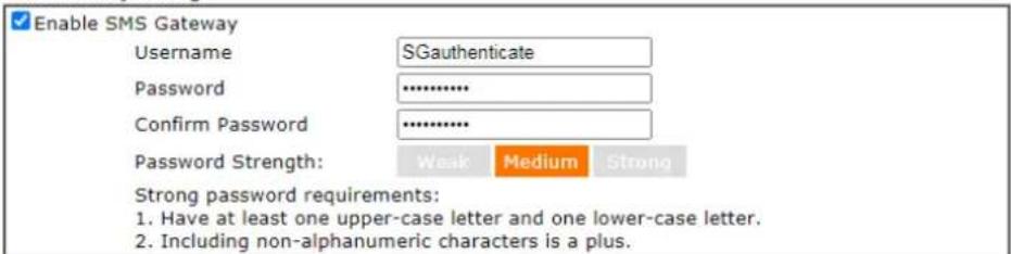
For router B, simply open LTE>>SMS Gateway and set a pair of username and password.
SMS Gateway Setting
text_image
Enable SMS Gateway Username SGauthenticate Password .......... Confirm Password .......... Password Strength: Weak Medium Strong Strong password requirements: 1. Have at least one upper-case letter and one lower-case letter. 2. Including non-alphanumeric characters is a plus.Note:
- Password can contain a-z A-Z 0-9, ; : . " < > " + = | ? @ # ^ ! ( )
- Password can't be all asterisks(*) . For example, '18' or '18:38' is illegal, but '123" or '45' is OK.
- Please enable HTTP or HTTPS server to allow SMS Gateway to work Remotely on System Maintenance >> Management page.
OK
Available settings are explained as follows:
| Item | Description |
| Enable SMS Gateway Check | the box to enable SMS gateway of this router. |
| Username Define a username. | |
| Password Define a password. | |
| Confirm Passowrd Enter the password again. |
Below shows the settings configured on Router A and Router B.
- Connect Router A and Router B (with LTE module).
- On Router B, set a pair of username (e.g., SGauthenticate) and password on LTE>>SMS Gateway.
LTE >> SMS Gateway
SMS Gateway Setting
text_image
Enable SMS Gateway Username: SGauthenticate Password: ********** Confirm Password: ********** Password Strength: Weak Medium Strong Strong password requirements: 1. Have at least one upper-case letter and one lower-case letter. 2. Including non-alphanumeric characters is a plus.Note:
- Password can contain a-z A-Z 0-9, ; :." < > " + = | ? @ # ^ ! ( )
- Password can't be all asterisks(*). For example, ^1 or ^1 is illegal, but '123*' or '45' is OK.
- Please enable HTTP or HTTPS server to allow SMS Gateway to work Remotely on System Maintenance >> Management page.
OK
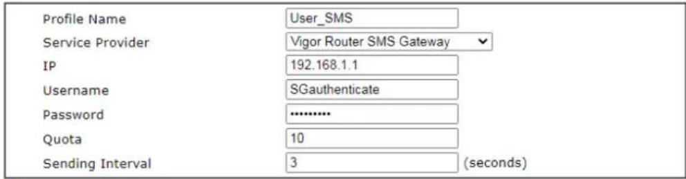
- On Router A, open Object Settings >> SMS Service Object >> Service Provider. Click any index number (e.g., #1 in this case) to open the following page. Select Vigor Router SMS Gateway as the service provider. Set the WAN IP or LAN IP of this router in IP field.
Objects Setting >> SMS Service Object
Profile Index: 1
text_image
Profile Name User_SMS Service Provider Vigor Router SMS Gateway IP 192.168.1.1 Username SGauthenticate Password .......... Quota 10 Sending Interval 3 (seconds)Note:
- Only one message can be sent during the "Sending Interval" time.
- If the "Sending Interval" was set to 0, there will be no limitation.

As for username and password, please enter the same values as configured in Step 2.
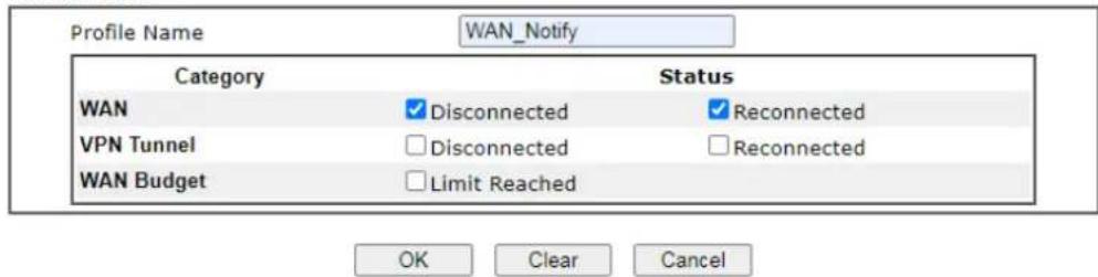
- Next, go to Objects Setting >> Notification Object. Select disconnection or connection of WAN, VPN tunnel and click OK to save the setting on Router A.
Objects Setting >> Notification Object
Profile Index: 1
text_image
Profile Name WAN_Notify Category Status WAN ✓ Disconnected ✓ Reconnected VPN Tunnel □ Disconnected □ Reconnected WAN Budget □ Limit Reached OK Clear Cancel- Once the router A encounters the condition set above, router B (as an SMS gateway) will send out an SMS to the recipient.
For a user who owns a non-DrayTek LTE router, there is one way to send the SMS to mobile phones through the non-DrayTek LTE router and DrayTek router.
-
Make sure the DrayTek router and the non-DrayTek LTE router are connected via LAN.
-
Obtain the exact URL string from non-DrayTek LTE router.
-
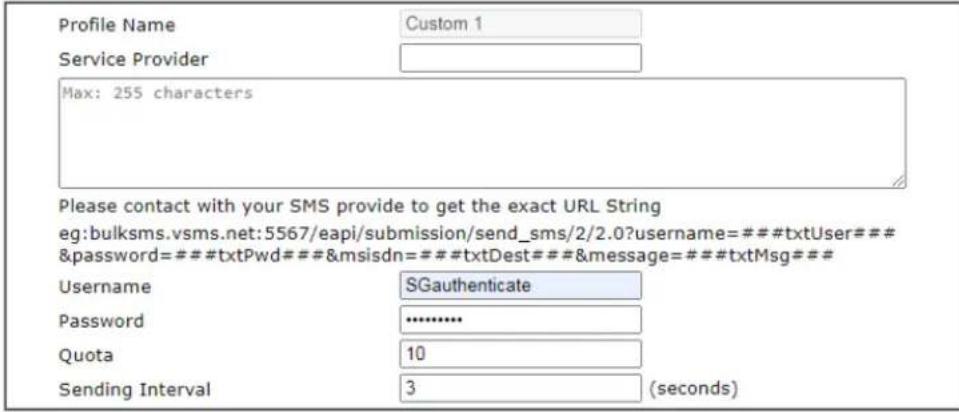
On DrayTek router, open Objects Setting>>SMS Service Object and click the number link #9 or #10 to customize SMS service object.
Objects Setting >> SMS Service Object
Profile Index: 9
text_image
Profile Name Custom 1 Service Provider Max: 255 characters Please contact with your SMS provide to get the exact URL String eg:bulksms.vsms.net:5567/eapi/submission/send_sms/2/2.0?username=###txtUser### &password=###txtPwd###&msisdn=###txtDest###&message=###txtMsg### Username SGauthenticate Password ****** Quota 10 Sending Interval 3 (seconds)Note:
-
Only one message can be sent during the "Sending Interval" time.
-
If the "Sending Interval" was set to 0, there will be no limitation.

Enter the data coming from the non-DrayTek LTE router, e.g., the URL string, the username, password, and warning message on the entry box.
- Click OK to save the settings.
II-1-5 Router Commands
This page allows the user to set function to reboot Vigor router remotely and get the router status via SMS.
Get Router Status or Reboot Router via SMS Message
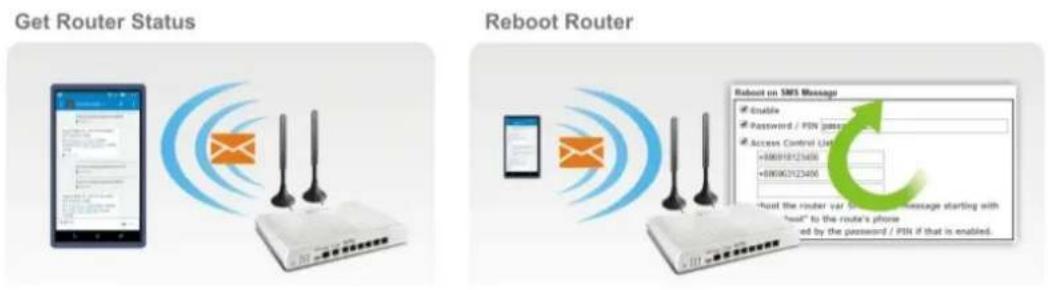
flowchart
graph LR
    A["Get Router Status"] --> B["Router"]
    C["Reboot Router"] --> D["Router"]
    B --> E["Mobile Phone"]
    D --> F["Password / PIN packet"]
    D --> G["Access Control List"]
    D --> H["Password/234M"]
    D --> I["Password/234M"]
    style B fill:#f9f,stroke:#333
    style D fill:#ccf,stroke:#333
Go to LTE>>Router Commands to get the following page.
LTE >> Router Commands
Reboot on SMS Message
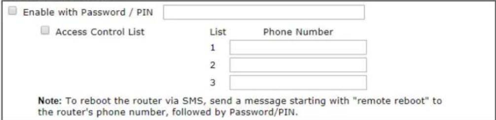
text_image
Enable with Password / PIN Access Control List List Phone Number 1 2 3 Note: To reboot the router via SMS, send a message starting with "remote reboot" to the router's phone number, followed by Password/PIN.Reply with Router Status Message
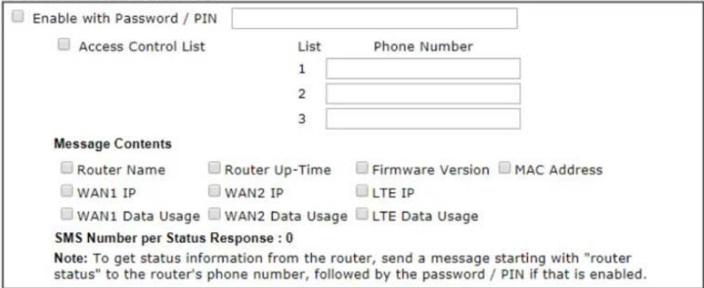
text_image
Enable with Password / PIN Access Control List List Phone Number 1 2 3 Message Contents Router Name Router Up-Time Firmware Version MAC Address WAN1 IP WAN2 IP LTE IP WAN1 Data Usage WAN2 Data Usage LTE Data Usage SMS Number per Status Response : 0 Note: To get status information from the router, send a message starting with "router status" to the router's phone number, followed by the password / PIN if that is enabled.Note: Phone numbers in the Access Control List should be in international format (e.g., +886123456789).
OK
Available settings are explained as follows:
| Item | Description |
| Reboot on SMS Message | |
| Enable with Password / PIN | To reboot Vigor router remotely via SMS, please check such box and type the password/ PIN number (treated asauthentication for any mobile phone).The password shall be composed by letters, numbers and baseline. |
| Access Control List Check the box to type or modify (up to 3) phone numbers.The phone number specified here is capable of sending SMS to reboot such Vigor router remotely.Note: If such option is enabled, only mobile phones specified here are allowed to send SMS to reboot Vigor router if correct password is given. That is, if it isdisabled(unchecked), any mobile phone can send SMS to reboot such Vigor router if correct password is given. | |
| Reply with Router Status Message | |
| Enable with Password / PIN | Users can get the WAN data usage and basic information about Vigor router (e.g., IP address, MAC address) through the mobile phone by entering the password/ PIN specified in this field.The password shall be composed by letters, numbers and baseline. |
| Access Control List Check the box to type or modify (up to 3) phone numbers.The phone number specified here is capable of getting related information about Vigor router remotely.Note: If such option is enabled, only mobile phones specified here are allowed to obtain related information about Vigor router if correct password is given. That is, if it isdisabled(unchecked), any mobile phone can get the data of Vigor router if correct password is given. | |
| Message Contents There are several types of message contents for you to select. Choose and check the required item, then Vigor router will offer the status response about that item via SMS. | |
| SMS messages per status response | Display the total number of the type for status response. Display the total number of SMS required to send the status message which contains the current selected Message Contents. |
II-1-6 Status
Vigor router with LTE function is capable of accessing into Internet and able to send SMS to specified mobile phone.
This page will display basic information about the embedded LTE module and the current LTE connection.
LTE >> Status
| Refresh
| LTE Modem | |
| Status: | Operational |
| IMEI: | 356318040749422 |
| IMSI: | 466924200859808 |
| ICCID: | --- |
| Access Tech: | LTE |
| Band: | E-UTRA Op Band 3 |
| Operator: | Chunghwa |
| Mobile Country Code: | 466 |
| Mobile Network Code: | 92 |
| Location Area Code: | 65534 |
| Cell ID: | 81023501 |
| RSSI Signal: | -61 dBm |
| Active Channel: | 1725 |
| Max Channel TX Rate: | 50 Mbps |
| Max Channel RX Rate: | 100 Mbps |
| LTE SMS | |
| SMS Centre Number: | +886932400821 |
| SMS Service Status: | Ready |
| SMS Loading: | Ready |
| New SMS: | 4 |
Each item is explained as follows:
| Item | Description |
| Status LTE WAN status. | |
| IMEI International Mobile Equipment Identity of the embedded LTE module. | |
| IMSI International Mobile Subscriber Identity of the LTE SIM card. | |
| Access Tech Type of LTE connection(CDMA/ GSM/ WCDMA/ LTE/ TD-SCDMA). | |
| Band Band of LTE connection. | |
| Operator ISP name of LTE connection. | |
| Mobile Country Code / Mobile Network Code / Location Area Code / Cell ID : | Base station information. |
| RSSI Signal Signal strength of LTE connection. | |
| Active Channel Frequency of LTE connection. | |
| Max Channel TX Rate / Maximum TX/ RX link rate of LTE connection. | |
| Max Channel RX Rate | |
| SMS Centre Number The phone number for SMS service of the LTE SIM card. | |
| SMS Service status Whether the SMS service of the LTE SIM card is ready. | |
| SMS Loading Whether the received SMS messages in the LTE SIM card have been loaded to the Router. | |
| New SMS The number of unread SMS in SMS Inbox. | |
II-2 WAN
It allows users to access Internet.
Basics of Internet Protocol (IP) Network
IP means Internet Protocol. Every device in an IP-based Network including routers, print server, and host PCs, needs an IP address to identify its location on the network. To avoid address conflicts, IP addresses are publicly registered with the Network Information Centre (NIC). Having a unique IP address is mandatory for those devices participated in the public network but not in the private TCP/IP local area networks (LANs), such as host PCs under the management of a router since they do not need to be accessed by the public. Hence, the NIC has reserved certain addresses that will never be registered publicly. These are known as private IP addresses, and are listed in the following ranges:
From 10.0.0.0 to 10.255.255.255
From 172.16.0.0 to 172.31.255.255
From 192.168.0.0 to 192.168.255.255
What are Public IP Address and Private IP Address
As the router plays a role to manage and further protect its LAN, it interconnects groups of host PCs. Each of them has a private IP address assigned by the built-in DHCP server of the Vigor router. The router itself will also use the default private IP address: 192.168.1.1 to communicate with the local hosts. Meanwhile, Vigor router will communicate with other network devices through a public IP address. When the data flow passing through, the Network Address Translation (NAT) function of the router will dedicate to translate public/private addresses, and the packets will be delivered to the correct host PC in the local area network. Thus, all the host PCs can share a common Internet connection.
Get Your Public IP Address from ISP
In ADSL deployment, the PPP (Point to Point)-style authentication and authorization is required for bridging customer premises equipment (CPE). Point to Point Protocol over Ethernet (PPPoE) connects a network of hosts via an access device to a remote access concentrator or aggregation concentrator. This implementation provides users with significant ease of use. Meanwhile it provides access control, billing, and type of service according to user requirement.
When a router begins to connect to your ISP, a serial of discovery process will occur to ask for a connection. Then a session will be created. Your user ID and password is authenticated via PAP or CHAP with RADIUS authentication system. And your IP address, DNS server, and other related information will usually be assigned by your ISP.
Web User Interface
WAN
General Setup
Internet Access
Multi-PVC/VLAN
WAN budget
LAN
II-2-1 General Setup
This section will introduce some general settings of Internet and explain the connection modes for LTE/WAN in details.
WAN >> General Setup
| Index | Enable | Physical Mode/Type | Active Mode |
| LTE | USB/- | Always On | |
| WAN2 | Ethernet/Auto negotiation | Failover |
Note:
-
One WAN interface can be active at any one time. Setting either WAN interface to "Always On" will set the other interface to operate as the "Fallover" WAN connection.
-
When WAN2 is enabled, LAN P2 port will be used as WAN2.
OK Cancel
Av
ailable settings are explained as follows:
| Item | Description |
| Index Click the LTE/ WAN interface link under Index to access into the WAN configuration page. | |
| Enable | V means such WAN interface is enabled and ready to be used. |
| Physical Mode / Type Display the physical mode and physical type of such WAN interface. | |
| Active Mode Display whether such WAN interface is Active device or backup device. | |
II-2-1-1 LTE
To use LTE network connection through LTE module, please configure LTE interface.
WAN >> General Setup
LTE

text_image
Enable: Yes Display Name: Physical Mode: USB Active Mode: Always On OK CancelAvailable settings are explained as follows:
| Item | Description |
| Enable | Choose Yes to invoke the settings for this WAN interface.Choose No to disable the settings for this WAN interface. |
| Display Name Enter the description for such WAN interface. | |
| Physical Mode Display the physical mode of this WAN interface. | |
| Active Mode In general, LTE | WAN is main interface and is always on forInternet connection. However, if WAN2 is enabled and set as Always On, the LTE WAN can be treated as backup WAN and allowed to be set as Always On or Failover. Always On - Make the LTE connection being activated always.Failover - Choose it to make the LTE connection as a backup connection. Always On - Make the LTE connection being activated always.Failover - Choose it to make the LTE connection as a backup connection. |
After finished the above settings, click OK to save the settings.
II-2-1-2 WAN2
Click WAN2 link to get the following page:
WAN >> General Setup
WAN 2
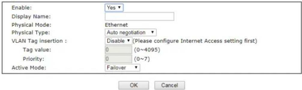
text_image
Enable: Display Name: Physical Mode: Physical Type: VLAN Tag insertion : Tag value: Priority: Active Mode: Yes ▼ Ethernet Auto negotiation ▼ Disable ▼ (Please configure Internet Access setting first) 0 (0~4095) 0 (0~7) Failover ▼ OK CancelAvailable settings are explained as follows:
| Item | Description |
| Enable | Choose Yes to invoke the settings for this WAN interface.Choose No to disable the settings for this WAN interface. |
| Display Name Enter the description for such WAN interface. | |
| Physical Mode Display the physical mode of this WAN interface. | |
| VLAN Tag insertion Enable - | Enable the function of VLAN with tag.The router will add specific VLAN number to all packets on the WAN while sending them out.Please Enter the tag value and specify the priority for the packets sending by WAN interface.Disable - Disable the function of VLAN with tag.Tag value - Enter the value as the VLAN ID number. The range is from 0 to 4095.Priority - Enter the packet priority number for such VLAN. The range is from 0 to 7. |
| Active Mode | Choose Always On to make the WAN connection being activated always.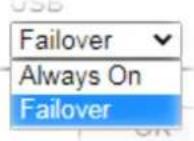 Failover - Choose it to make the WAN connection as a backup connection. Failover - Choose it to make the WAN connection as a backup connection. |
After finished the above settings, click OK to save the settings.
II-2-2 Internet Access
This page allows you to set WAN configuration with different modes.
WAN >> Internet Access
Internet Access
| Index | Display Name | Physical Mode | Access Mode | ||
| LTE | USB | None | Details Page | IPv6 | |
| WAN2 | Ethernet | None | Details Page | IPv6 | |
DHCP Client Option
Available settings are explained as follows:
| Item | Description |
| Index Display the WAN interface. | |
| Display Name It shows the name of the WAN1/ WAN2/ LTE that entered in general setup. | |
| Physical Mode It shows the physical connection for WAN (Ethernet or fiber) according to the real network connection. | |
| Access Mode Use the drop down list to choose a proper access mode. The details page of that mode will be popped up. If not, click Details Page for accessing the page to configure the settings. | |
| Details Page This button will open different web page (based on IPv4) according to the access mode that you choose in WAN interface. | |
| IPv6 | This button will open different web page (based on Physical Mode) to setup IPv6 Internet Access Mode for WAN interface. If IPv6 service is active on this WAN interface, the color of “IPv6” will become green. |
| DHCP Client Option | This button allows you to configure DHCP client options. DHCP packets can be processed by adding option number and data information when such function is enabled and configured.WAN >> Internet Access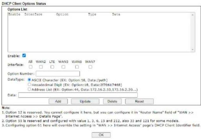 Enable - Check the box to enable the function of DHCPOption. Each DHCP option is composed by an option number with data. For example,Option number:100Data: abcdWhen such function is enabled, the specified values for DHCP option will be seen in DHCP reply packets.Interface - Specify the WAN interface(s) that will be overwritten by such function. WAN5 ~ WAN6 can be located under WAN>>Multi-PVC/VLAN.Option Number - Type a number for such function.Note: If you choose to configure option 61 here, the detailed settings in WAN>>Interface Access will be overwritten. Enable - Check the box to enable the function of DHCPOption. Each DHCP option is composed by an option number with data. For example,Option number:100Data: abcdWhen such function is enabled, the specified values for DHCP option will be seen in DHCP reply packets.Interface - Specify the WAN interface(s) that will be overwritten by such function. WAN5 ~ WAN6 can be located under WAN>>Multi-PVC/VLAN.Option Number - Type a number for such function.Note: If you choose to configure option 61 here, the detailed settings in WAN>>Interface Access will be overwritten. |
| DataType - Choose the type (ASCII or Hex) for the data to be stored.Data - Enter the content of the data to be processed by the function of DHCP option. | |
II-2-2-1 Details Page for 3G/4G LTE Modem (DHCP mode) in LTE WAN
LTE WAN uses the embedded LTE module to access internet.
To use 3G/4G LTE Modem (DHCP mode) as the accessing protocol of the internet, please choose Internet Access from WAN menu. Then, select 3G/4G LTE Modem (DHCP mode) for LTE. The following web page will be shown.
LTE
| 3G/4G LTE Modem(DHCP mode) | IPv6 |
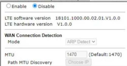 | |
| SIM1 SettingsSIM PIN codeNetwork Mode 4G/3G (Default:4G/3G)APN NameDisable Auto APN |  |
| Keep WAN ConnectionEnable PING to keep alive (Timeout: 10 secs.)PING to the IP 8.8.8.8Connection Latency CheckLatency 800 msLatency Duration 60 seconds | SIM2 SettingsSIM PIN codeNetwork Mode 4G/3G (Default:4G/3G)APN NameDisable Auto APN |
| Authentication PAP or CHAPUsername(Optional)Password(Optional) | Keep WAN ConnectionEnable PING to keep alive (Timeout: 10 secs.)PING to the IP 8.8.8.8Authentication PAP or CHAPUsername(Optional)Password(Optional) |
| SIM1 failoverDial-up timeout 50 (50 ~ 255 secs.)Threshold of fail count 2 (2 ~ 20 times.)Enable Data Budget | SIM2 failoverDial-up timeout 50 (50 ~ 255 secs.)Threshold of fail count 2 (2 ~ 20 times.)Enable Data Budget |
SIM1 Settings
| SIM PIN code | ||
| Network Mode | 4G/3G | (Default:4G/3G) |
| APN Name | ||
| Disable Auto APN | ||
| Keep WAN Connection | ||
| Enable PING to keep alive (Timeout: 10 secs.) | ||
| PING to the IP | 8.8.8.8 | |
| Connection Latency Check | ||
| Latency | 800 | ms |
| Latency Duration | 60 | seconds |
| Authentication | PAP or CHAP | |
| Username | (Optional) | |
| Password | (Optional) | |
| SIM1 failover | ||
| Dial-up timeout | 50 | (50 ~ 255 secs.) |
| Threshold of fail count | 2 | (2 ~ 20 times.) |
| Enable Data Budget | ||
SIM2 Settings
| SIM PIN code | |
| Network Mode | 4G/3G ▼ (Default:4G/3G) |
| APN Name | |
| Disable Auto APN | |
| Keep WAN Connection | |
| Enable PING to keep alive (Timeout: 10 secs.) | |
| PING to the IP | 8.8.8.8 |
| Authentication | PAP or CHAP▼ |
| Username | (Optional) |
| Password | (Optional) |
| SIM2 failover | |
| Dial-up timeout | 50 (50 ~ 255 secs.) |
| Threshold of fail count | 2 (2 ~ 20 times.) |
| Enable Data Budget | |
Note:
1. Only one SIM will be used at the same time.
SIM1 (the lower SIM slot) has a higher priority by default.
2. Preferred LTE band setting will take effect until next LTE connection.

Available settings are explained as follows:
| Item | Description |
| Enable | Click Enable for activating this function. If you click Disable, this function will be closed and all the settings that you adjusted in this page will be invalid. |
| LTE hardware version The | hardware version of the embedded LTE module. |
| WAN Connection Detection | Such function allows you to verify whether network connection is alive or not through ARP Detect or Ping Detect.Mode - Choose ARP Detect or Ping Detect for the system to execute for WAN detection. If you choose Ping Detect as the detection mode, you have to type required settings for the following items.Primary/Secondary Ping IP - If you choose Ping Detect as detection mode, you have to type Primary or Secondary IP address in this field for pinging.Ping Gateway IP - If you choose Ping Detect as detection mode, you also can enable this setting to use current WAN gateway IP address for pinging.With the IP address(es) pinging, Vigor router can check if the WAN connection is on or off.TTL (Time to Live) - Set TTL value of PING operation.Ping Interval - Type the interval for the system to execute the PING operation.Ping Retry - Type the number of times that the system is allowed to execute the PING operation before WAN disconnection is judged. |
| MTU It means Max Transmit | Unit for packet.Path MTU Discovery - It is used to detect the maximum MTU size of a packet not to be segmented in specific transmit path.Click Choose IP to open the following dialog.172.17.11.1/doc/pathmtu.htmPath MTU to: IPv4 HostMTU reduce size by 8DetectNote: You may reduce the Path MTU Size(max 1500) by 1 to 100.Accept CancelPath MTU to - Type the IP address as the specific transmit path.MTU reduce size by - It determines the decreasing size of MTU value. For example, the number specified in this field is “8”. The maximum MTU size is “1500”. After clicking the “detect” button, the system will calculate and get the suitable MTU value such as 1500, 1492, 1484 and etc., automatically.Detect - Click it to detect a suitable MTU value.Accept - After clicking it, the detected value will be displayed in the field of MTU. |
| Preferred LTE Band Click the link to open a pop-up dialog.Different ISPs can offer various LTE bands. Available legal bands will be shown on the screen based on the operational bands offered by YOUR ISP. In default, all the bands are enabled.Choose one or multiple bands if you want to change. If not, keep the default configuration.Enable Bridge Mode (Use LAN Port P1) - DHCP client (a PC or other router) connected to LAN Port P1 is able to get WAN IP to access Internet from LTE WAN interface.Bridge Specific MAC Address - Enter the MAC address of the DHCP client (a PC or a router) manually to get the WAN IP.First priority for dialing up - Select SIM1 or SIM2 as the first priority for dialing up. The default setting is SIM1. | |
| SIM1 Settings | |
| SIM PIN code | Type PIN code of the SIM card that will be used to access Internet.The maximum length of the PIN code you can set is 19characters. |
| Network Mode | Force Vigor router to connect Internet with the mode specified here. If you choose 4G/3G/2G as network mode, the router will choose a suitable one according to the actual wireless signal automatically. |
| APN Name APN means Access | Point Name which is provided and required by some ISPs. Type the name and clickApply.The maximum length of the name you can set is 47 characters. |
| Keep WAN Connection | Normally, this function is designed for Dynamic IP environments because some ISPs will drop connections if there is no traffic within certain periods of time. CheckEnable PING to keep alivebox to activate this function.Enable PING to Keep alive- If you enable the PING function, please specify an IP address for the system to PING it for keeping alive. Vigor system will send a packet per second to the specified IP address. If the system does not receive any reply from that IP within 10 seconds, Vigor system will reboot LTE module until successfully set LTE connection.PING to the IP - Enter an IP address.Connection Latency Check- Enable the latency time setting for packet reply. If it is enabled (checked), Vigor system will wait for the packet reply from the specified IP address.When the time of waiting packet reply reaches the time threshold (defined in Latency) and continues for a period of time (defined in Latency Duration), Vigor system will reboot LTE module until successfully set LTE connection.Latency- Set a time threshold for packet reply. Default value is 800 (unit: micro-second).Latency Duration- Set a time period. Default value is 60 (unit: second).Authentication - Select None or PAP or CHAP.UserName- Enter the username (optional). The maximum length of the name you can set is 47 characters.Password- Enter the password (optional). The maximum length of the password you can set is 62 characters. |
| SIM2 Settings | |
| SIM PIN code | Type PIN code of the SIM card that will be used to access Internet.The maximum length of the PIN code you can set is 19 characters. |
| Network Mode | Force Vigor router to connect Internet with the mode specified here. If you choose 4G/3G/2G as network mode, the router will choose a suitable one according to the actual wireless signal automatically. |
| APN Name APN means Access | Point Name which is provided and required by some ISPs. Type the name and clickApply.The maximum length of the name you can set is 47 characters. |
| Keep WANConnection | Normally, this function is designed for Dynamic IP environments because some ISPs will drop connections if there is no traffic within certain periods of time. CheckEnable PING to keep alivebox to activate this function.Enable PING to Keep alive - If you enable the PING function, please specify an IP address for the system to PING it for keeping alive. Vigor system will send a packet per second to the specified IP address. If the system does not receive any reply from that IP within 10 seconds, Vigor system will reboot LTE module until successfully set LTE connection.PING to the IP - Enter an IP address.Authentication - Select None or PAP or CHAP.UserName - Enter the username (optional). The maximum length of the name you can set is 47 characters.Password - Enter the password (optional). The maximum length of the password you can set is 62 characters. |
| SIM1/SIM2 failover Dial-up | timeout - Set the time out interval (50 to 255 seconds).Threshold of fail count - Set the maximum times (2 to 20) of failed dial-ups. After that, the system will stop dial-up and use another SIM card for dial-up instead.Enable Data Budget - When selected, WAN Budget is enabled for this WAN.Quota Limit - Enter the data traffic quota allowed for such WAN interface. There are two unit (MB and GB) offered for you to specify.When quota exceeded: Shutdown WAN interface - All the outgoing traffics through the WAN interface will be terminated.Send alert SMS to - The system will send out a warning message to a specified mail address when the quota is running out. However, the connection charges will be calculated continuously.Quota resets on day - Some ISP might apply for the network limitation based on the traffic limit per month. This setting is to offer a mechanism for resetting the traffic record every month. You can determine the starting day in one month. |
After finishing all the settings here, please click OK to activate them.
II-2-2-2 Details Page for PPPoE in WAN2
To choose PPPoE as the accessing protocol of the Internet, please select PPPoE from the WAN>>Internet Access >>WAN2 page. The following web page will be shown.
WAN >> Internet Access
WAN 2
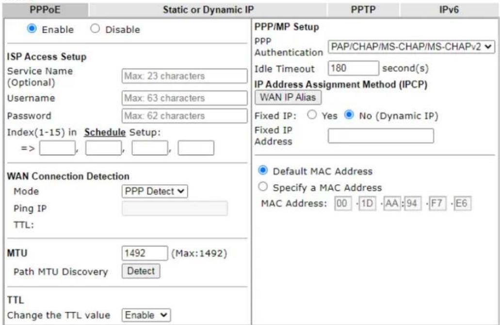
text_image
PPPoE Static or Dynamic IP PPTP IPv6 Enable Disable ISP Access Setup Service Name Max: 23 characters (Optional) Username Max: 63 characters Password Max: 62 characters Index(1-15) in Schedule Setup: => , , , , , WAN Connection Detection Mode PPP Detect Ping IP TTL: MTU 1492 (Max:1492) Path MTU Discovery Detect TTL Change the TTL value Enable PPP/MP Setup PPP PAP/CHAP/MS-CHAP/MS-CHAPv2 Authentication Idle Timeout 180 second(s) IP Address Assignment Method (IPCP) WAN IP Alias Fixed IP: Yes No (Dynamic IP) Fixed IP Address Default MAC Address Specify a MAC Address MAC Address: 00 · 1D · AA : 94 · F7 · E6
Available settings are explained as follows:
| Item | Description |
| Enable/Disable | Click Enable for activating this function. If you click Disable, this function will be closed and all the settings that you adjusted in this page will be invalid. |
| ISP Access Setup Enter your | allocated username, password and authentication parameters according to the information provided by your ISP.Service Name - Enter the description of the specific network service.Usage - Type in the username provided by ISP in this field.The maximum length of the user name you can set is 63 characters.Password - Type in the password provided by ISP in this field.The maximum length of the password you can set is 62 characters.Index (1-15) - You can type in four sets of time schedule for your request. All the schedules can be set previously in Applications >> Schedule web page and you can use the number that you have set in that web page. |
| WAN Connection Detection | Such function allows you to verify whether network connection is alive or not through PPP Detect or Ping Detect.Mode - Choose PPP Detect or Ping Detectfor the system to execute for WAN detection. If you choose Ping Detect as the detection mode, you have to type required settings for the following items.Primary/Secondary Ping IP - If you choose Ping Detectas detection mode, you have to type Primary or Secondary IP address in this field for pinging.Ping Gateway IP - If you choose Ping Detectas detection mode, you also can enable this setting to use current WAN gateway IP address for pinging.With the IP address(es) pinging, Vigor router can check if the WAN connection is on or off.TTL (Time to Live) - Set TTL value of PING operation.Ping Interval - Type the interval for the system to execute the PING operation.Ping Retry - Type the number of times that the system is allowed to execute the PING operation before WAN disconnection is judged. |
| MTU It means Max Transmit | Unit for packet.Path MTU Discovery- It is used to detect the maximum MTU size of a packet not to be segmented in specific transmit path.ClickDetectto open the following dialog.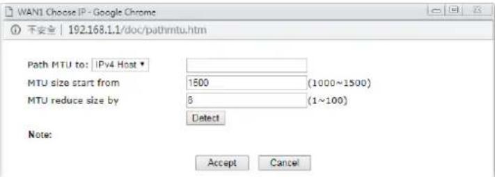 Path MTU to - Type the IP address as the specific transmit path.MTU size start from - Determine the starting point value of the packet. Default setting is 1500.MTU reduce size by - It determines the decreasing size of MTU value. For example, the number specified in this field is “8”. The maximum MTU size is “1500”. After clicking the “detect” button, the system will calculate and get the suitable MTU value such as 1500, 1492, 1484 and etc., automatically.Detect- Click it to detect a suitable MTU valueAccept- After clicking it, the detected value will be displayed in the field of MTU. Path MTU to - Type the IP address as the specific transmit path.MTU size start from - Determine the starting point value of the packet. Default setting is 1500.MTU reduce size by - It determines the decreasing size of MTU value. For example, the number specified in this field is “8”. The maximum MTU size is “1500”. After clicking the “detect” button, the system will calculate and get the suitable MTU value such as 1500, 1492, 1484 and etc., automatically.Detect- Click it to detect a suitable MTU valueAccept- After clicking it, the detected value will be displayed in the field of MTU. |
| TTL Change the TTL value | - Enable or disable the TTL (Time to Live) for a packet transmitted through Vigor router.Enable- TTL value will be reduced (-1) when it passes through Vigor router. It will cause the client, accessing Internet through Vigor router, be blocked by certain ISP when TTL value becomes “0”.Disable- TTL value will not be reduced. Then, when a packet passes through Vigor router, it will not be cancelled. That is, the client who sends out the packet will not be blocked by ISP. |
| PPP/MP Setup | PPP Authentication – Select PAP only or PAP or CHAP for PPP.Idle Timeout- Set the timeout for breaking down the Internet after passing through the time without any action.IP Assignment (IPCP)- Usually ISP dynamically assigns IP address to you each time you connect to it and request. In some case, your ISP provides service to always assign you the same IP address whenever you request. In this case, you can fill in this IP address in the Fixed IP field. Please contact your ISP before you want to use this function.WAN IP Alias - If you have multiple public IP addresses and would like to utilize them on the WAN interface, please use WAN IP Alias. You can set up to 8 public IP addresses other than the current one you are using. Notice that this setting is available for WAN1 only. Type the additional WAN IP address and check the Enable box. Then click OK to exit the dialog.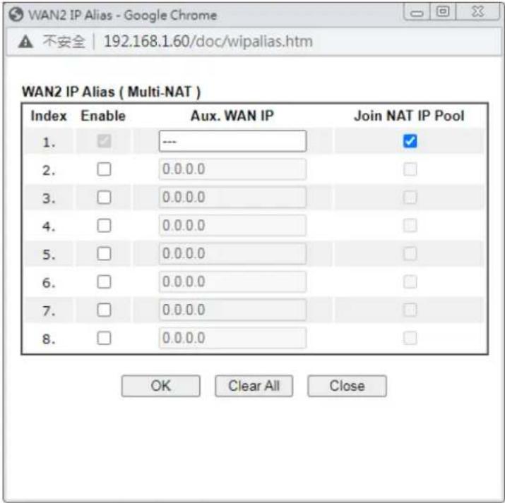 Fixed IP Address - Type in a fixed IP address.Default MAC Address - You can use Default MAC Address or specify another MAC address by typing on the boxes of MAC Address for the router.Specify a MAC Address - Type the MAC address for the router manually. Fixed IP Address - Type in a fixed IP address.Default MAC Address - You can use Default MAC Address or specify another MAC address by typing on the boxes of MAC Address for the router.Specify a MAC Address - Type the MAC address for the router manually. |
After finishing all the settings here, please click OK to activate them.
II-2-2-3 Details Page for Static or Dynamic IP in WAN2
For static IP mode, you usually receive a fixed public IP address or a public subnet, namely multiple public IP addresses from your DSL or Cable ISP service providers. In most cases, a Cable service provider will offer a fixed public IP, while a DSL service provider will offer a public subnet. If you have a public subnet, you could assign an IP address or many IP address to the WAN interface.
To use Static or Dynamic IP as the accessing protocol of the internet, please click the Static or Dynamic IP tab. The following web page will be shown.
WAN 2
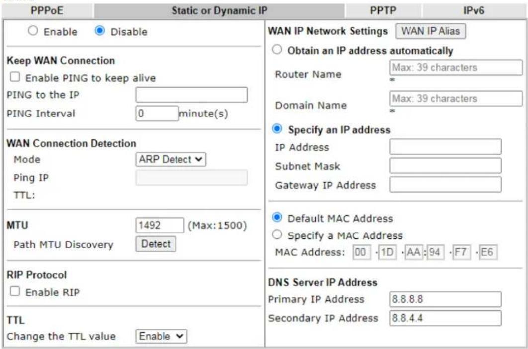
text_image
PPPoE Static or Dynamic IP PPTP IPv6 Enable Disable WAN IP Network Settings WAN IP Alias Obtain an IP address automatically Router Name Max: 39 characters Domain Name Max: 39 characters Specify an IP address IP Address Subnet Mask Gateway IP Address MTU 1492 (Max:1500) Path MTU Discovery Detect Default MAC Address Specify a MAC Address MAC Address: 00 · 1D · AA: 94 · F7 · E6 DNS Server IP Address Primary IP Address 8.8.8.8 Secondary IP Address 8.8.4.4 Keep WAN Connection Enable PING to keep alive PING to the IP PING Interval 0 minute(s) WAN Connection Detection Mode ARP Detect Ping IP TTL: RIP Protocol Enable RIP TTL Change the TTL value Enable*: Required for some ISPs
OK
Cancel
Available settings are explained as follows:
| Item | Description |
| Enable / Disable | Click Enable for activating this function. If you click Disable, this function will be closed and all the settings that you adjusted in this page will be invalid. |
| Keep WAN Connection | Normally, this function is designed for Dynamic IP environments because some ISPs will drop connections if there is no traffic within certain periods of time. Check Enable PING to keep alive box to activate this function.PING to the IP - If you enable the PING function, please specify the IP address for the system to PING it for keeping alive.PING Interval - Enter the interval for the system to execute the PING operation. |
| WAN Connection Detection | Such function allows you to verify whether network connection is alive or not through ARP Detect or Ping Detect.Mode - Choose ARP Detect, Ping Detect or Always On for the system to execute for WAN detection. If you choose Ping Detect as the detection mode, you have to type required settings for the following items.Primary/Secondary Ping IP - If you choose Ping Detect as detection mode, you have to type Primary or Secondary IP address in this field for pinging.Ping Gateway IP - If you choose Ping Detect as detection mode, you also can enable this setting to use current WAN gateway IP address for pinging.With the IP address(es) pinging, Vigor router can check if the WAN connection is on or off.TTL (Time to Live) - Set TTL value of PING operation.Ping Interval - Enter the interval for the system to execute the PING operation.Ping Retry - Enter the number of times that the system is allowed to execute the PING operation before WAN disconnection is judged. |
| MTU It means Max Transmit | Unit for packet.Path MTU Discovery - It is used to detect the maximum MTU size of a packet not to be segmented in specific transmit path.Click Detect to open the following dialog.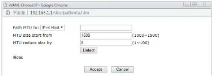 Path MTU to - Choose the destination as the specific transmit path and Enter the IP address.MTU size start from - Determine the starting point value of the packet.MTU reduce size by - It determines the decreasing size of MTU value. For example, the number specified in this field is “8”. The maximum MTU size is “1500”. After clicking the “detect” button, the system will calculate and get the suitable MTU value such as 1500, 1492, 1484 and etc., automatically.Detect - Click it to detect a suitable MTU valueAccept - After clicking it, the detected value will be displayed in the field of MTU. Path MTU to - Choose the destination as the specific transmit path and Enter the IP address.MTU size start from - Determine the starting point value of the packet.MTU reduce size by - It determines the decreasing size of MTU value. For example, the number specified in this field is “8”. The maximum MTU size is “1500”. After clicking the “detect” button, the system will calculate and get the suitable MTU value such as 1500, 1492, 1484 and etc., automatically.Detect - Click it to detect a suitable MTU valueAccept - After clicking it, the detected value will be displayed in the field of MTU. |
| RIP Protocol | Routing Information Protocol is abbreviated as RIP (RFC1058) specifying how routers exchange routing tables information.Click Enable RIP for activating this function. |
| TTL Change the TTL value | - Enable or disable the TTL (Time to Live) for a packet transmitted through Vigor router.Enable - TTL value will be reduced (-1) when it passes through Vigor router. It will cause the client, accessing Internet through Vigor router, be blocked by certain ISP when TTL value becomes “0”.Disable - TTL value will not be reduced. Then, when a packet passes through Vigor router, it will not be cancelled. That is, the client who sends out the packet will not be blocked by ISP. |
| WAN IP Network Settings | This group allows you to obtain an IP address automatically and allows you Enter IP address manually.WAN IP Alias - If you have multiple public IP addresses and would like to utilize them on the WAN interface, please use WAN IP Alias. You can set up to 8 public IP addresses other than the current one you are using.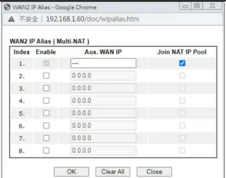 |
| Obtain an IP address automatically - Click this button to obtain the IP address automatically if you want to use Dynamic IP mode.● Router Name: Enter the router name provided by ISP.● Domain Name: Enter the domain name that you have assigned.Specify an IP address - Click this radio button to specify some data if you want to use Static IP mode.● IP Address: Enter the IP address.● Subnet Mask: Enter the subnet mask.● Gateway IP Address: Enter the gateway IP address.Default MAC Address: Click this radio button to use default MAC address for the router.Specify a MAC Address: Some Cable service providers specify a specific MAC address for access authentication. In such cases you need to click the Specify a MAC Address and enter the MAC address in the MAC Address field. | |
| DNS Server IP Address Enter | the primary IP address for the router if you want to use Static IP mode. If necessary, Enter secondary IP address for necessity in the future. |
After finishing all the settings here, please click OK to activate them.
II-2-2-4 Details Page for PPTP
To use PPTP as the accessing protocol of the internet, please click the PPTP tab. The following web page will be shown.
WAN >> Internet Access
WAN 2
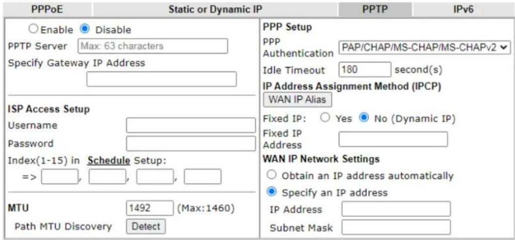
text_image
PPPoE Static or Dynamic IP Enable Disable PPTP Server Max: 63 characters Specify Gateway IP Address ISP Access Setup Username Password Index(1-15) in Schedule Setup: => , , , , , MTU 1492 (Max:1460) Path MTU Discovery Detect PPP Setup PPP Authentication PAP/CHAP/MS-CHAP/MS-CHAPv2 Idle Timeout 180 second(s) IP Address Assignment Method (IPCP) WAN IP Alias Fixed IP: Yes No (Dynamic IP) Fixed IP Address WAN IP Network Settings Obtain an IP address automatically Specify an IP address IP Address Subnet Mask PPP
Available settings are explained as follows:
| Item | Description |
| PPTP | Enable - Click this radio button to enable a PPTP client to establish a tunnel to a DSL modem on the WAN interface.Disable - Click this radio button to close the connection through PPTP.PPTP Server - Specify the IP address of the PPTP server if you enable PPTP client mode.Specify Gateway IP Address - Specify the gateway IP address for DHCP server. |
| ISP Access Setup Username | -Enter the username provided by ISP in this field.The maximum length of the user name you can set is 63 characters.Password -Enter the password provided by ISP in this field.The maximum length of the password you can set is 62 characters.Index (1-15) in Schedule Setup - You can Enter four sets of time schedule for your request. All the schedules can be set previously in Application >> Schedule web page and you can use the number that you have set in that web page. |
| MTU It means Max Transmit | Unit for packet.Path MTU Discovery - It is used to detect the maximum MTU size of a packet not to be segmented in specific transmit path.Click Detect to open the following dialog.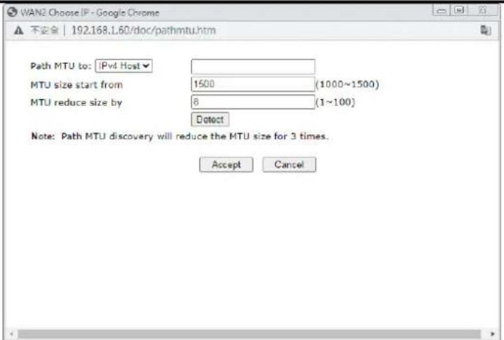 |
| Path MTU to - Choose the destination as the specific transmit path and Enter the IP address.MTU size start from - Determine the starting point value of the packet.MTU reduce size by - It determines the decreasing size of MTU value. For example, the number specified in this field is “8”. The maximum MTU size is “1500”. After clicking the “detect” button, the system will calculate and get the suitable MTU value such as 1500, 1492, 1484 and etc., automatically.Detect - Click it to detect a suitable MTU valueAccept - After clicking it, the detected value will be displayed in the field of MTU. | |
| PPP Setup | PPP Authentication - Select PAP only or PAP or CHAP for PPP.Idle Timeout - Set the timeout for breaking down the Internet after passing through the time without any action. |
| IP Address Assignment Method(IPCP) | WAN IP Alias - If you have multiple public IP addresses and would like to utilize them on the WAN interface, please use WAN IP Alias. You can set up to 8 public IP addresses other than the current one you are using.Fixed IP - Usually ISP dynamically assigns IP address to you each time you connect to it and request. In some case, your ISP provides service to always assign you the same IP address whenever you request. In this case, you can fill in this IP address in the Fixed IP field. Please contact your ISP before you want to use this function. Click Yes to use this function and Enter a fixed IP address in the box.Fixed IP Address -Type a fixed IP address. |
| WAN IP Network Settings | Obtain an IP address automatically - Click this button to obtain the IP address automatically.Specify an IP address - Click this radio button to specify some data.IP Address - Enter the IP address.Subnet Mask - Enter the subnet mask. |
After finishing all the settings here, please click OK to activate them.
II-2-2-5 Details Page for IPv6 – Offline
When Offline is selected, the IPv6 connection will be disabled.
Internet Access >> IPv6
WAN 2

text_image
Internet Access Mode Connection Type OfflineOK
II-2-2-6 Details Page for IPv6 – PPP
During the procedure of IPv4 PPPoE connection, we can get the IPv6 Link Local Address between the gateway and Vigor router through IPv6CP. Later, use DHCPv6 or accept RA to acquire the IPv6 prefix address (such as: 2001:B010:7300:200::/64) offered by the ISP. In addition, PCs under LAN also can have the public IPv6 address for Internet access by means of the generated prefix.
No need to type any other information for PPP mode.
Internet Access >> IPv6
WAN 2
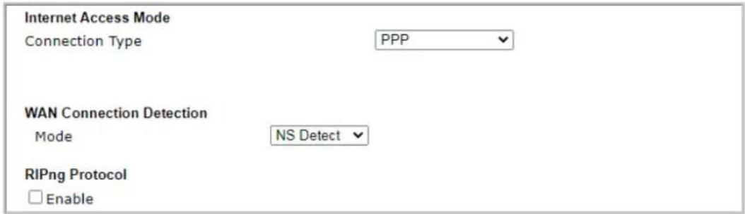
text_image
Internet Access Mode Connection Type PPP WAN Connection Detection Mode NS Detect RIPng Protocol EnableNote:
IPv4 WAN setting should be PPPoE / PPPoA client.
OK
Available settings are explained as follows:
| Item | Description |
| WAN Connection Detection | Such function allows you to verify whether network connection is alive or not through Ping Detect. Mode - Choose NS Detect, Always On or Ping Detect for the system to execute for WAN detection. Always On means no detection will be executed. The network connection will be on always.● Ping IP/Hostname - If you choose Ping Detect as detection mode, you have to type IP address in this field for pinging.● TTL (Time to Live) -If you choose Ping Detect as detection mode, you have to type TTL value. |
RIPng Protocol RIPng (RIP next generation) offers the same functions and benefits as IPv4 RIP v2.
Below shows an example for successful IPv6 connection based on PPP mode.
Online Status
| Physical Connection | System Uptime: 0:2:32 | |||
| IPv4 | IPv6 | |||
| LAN Status | ||||
| IP Address | ||||
| 2001:B010:7300:201:21D:AAFF:FEA6:2568/64 (Global) | ||||
| FE80::21D:AAFF:FEA6:2568/64 (Link) | ||||
| TX Packets | RX Packets | TX Bytes | RX Bytes | |
| 7 | 4 | 690 | 328 | |
| WAN2 IPv6 Status | >> Drop PPP | |||
| Enable | Mode | Up Time | ||
| Yes | PPP | 0:02:08 | ||
| IP | Gateway IP | |||
| 2001:B010:7300:201:21D:AAFF:FEA6:256A/128 (Global) | FE80::90:1A00:242:AD52 | |||
| FE80::1D:AAFF:FEA6:256A/128 (Link) | ||||
| DNS IP | ||||
| 2001:B000:168::1 | ||||
| 2001:B000:168::2 | ||||
| TX Packets | RX Packets | TX Bytes | RX Bytes | |
| 7 | 9 | 544 | 1126 | |

Info
At present, the IPv6 prefix can be acquired via the PPPoE mode connection which is available for the areas such as Taiwan (hinet), the Netherlands, Australia and UK.
II-2-2-7 Details Page for IPv6 – TSPC
Tunnel setup protocol client (TSPC) is an application which could help you to connect to IPv6 network easily.
Please make sure your IPv4 WAN connection is OK and apply one free account from hexago (http://gogonet.gogo6.com/page/freenet6-account) before you try to use TSPC for network connection. TSPC would connect to tunnel broker and requests a tunnel according to the specifications inside the configuration file. It gets a public IPv6 IP address and an IPv6 prefix from the tunnel broker and then monitors the state of the tunnel in background.
After getting the IPv6 prefix and starting router advertisement daemon (RADVD), the PC behind this router can directly connect to IPv6 the Internet.
Internet Access >> IPv6
WAN 2
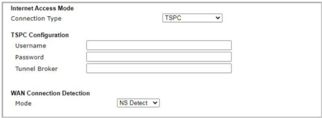
text_image
Internet Access Mode Connection Type TSPC TSPC Configuration Username Password Tunnel Broker WAN Connection Detection Mode NS DetectOK
Available settings are explained as follows:
| Item | Description |
| Username Enter the name obtained from the broker. It is suggested for you to apply another username and password for http://gogonet.gogo6.com/page/freenet6-account.The maximum length of the name you can set is 63 characters. | |
| Password Enter the password assigned with the user name.The maximum length of the name you can set is 19 characters. | |
| Tunnel Broker | Enter the address for the tunnel broker IP, FQDN or an optional port number. |
| WAN Connection Detection | Such function allows you to verify whether network connection is alive or not through Ping Detect.Mode - Choose NS Detect, Always On or Ping Detect for the system to execute for WAN detection. Always On means no detection will be executed. The network connection will be on always.Ping IP/Hostname - If you choose Ping Detect as detection mode, you have to type IP address in this field for pinging.TTL (Time to Live) -If you choose Ping Detect as detection mode, you have to type TTL value. |
After finished the above settings, click OK to save the settings.
II-2-2-8 Details Page for IPv6 – AICCU
Internet Access >> IPv6
WAN 2
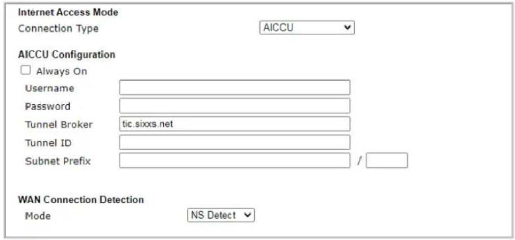
text_image
Internet Access Mode Connection Type AICCU AICCU Configuration □ Always On Username Password Tunnel Broker tic.sixxs.net Tunnel ID Subnet Prefix / WAN Connection Detection Mode NS DetectNote:
If "Always On" is not enabled, AICCU connection would only retry three times.
OK
Available settings are explained as follows:
| Item | Description |
| Always On Check this box to | keep the network connection always. |
| Username Enter the name obtained from the broker. Please apply new account at http://www.sixxs.net/. It is suggested for you to apply another username and password.The maximum length of the name you can set is 19 characters. | |
| Password Enter the password assigned with the user name.The maximum length of the password you can set is 19 characters. | |
| Tunnel Broker It means a server of AICCU. The server can provide IPv6 tunnels to sites or end users over IPv4.Enter the address for the tunnel broker IP, FQDN or an optional port number. | |
| Tunnel ID One user account may have several tunnels. And, each tunnel shall have one specified tunnel ID (e.g., T115394).Enter the ID offered by Tunnel Broker. | |
| Subnet Prefix Enter the subnet prefix address obtained from service provider.The maximum length of the prefix you can set is 128 characters. | |
| WAN Connection Detection Such function allows you to verify whether network connection is alive or not through Ping Detect.Mode - Choose NS Detect, Always On or Ping Detect for the system to execute for WAN detection.Ping IP/Hostname - If you choose Ping Detect as detection mode, you have to type IP address in this field | |
| for pinging.●TTL (Time to Live) -If you choose Ping Detect as detection mode, you have to type TTL value. | |
After finished the above settings, click OK to save the settings.
II-2-2-9 Details Page for IPv6 – DHCPv6 Client
DHCPv6 client mode would use DHCPv6 protocol to obtain IPv6 address from server.
Internet Access >> IPv6
WAN 2
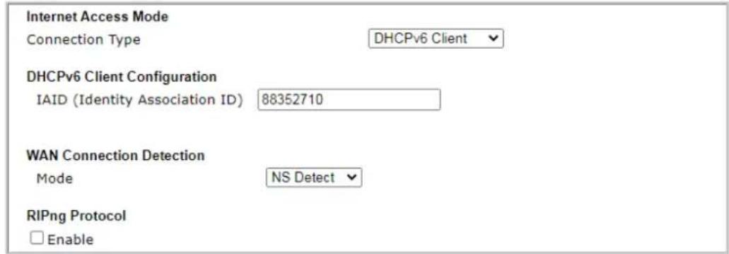
text_image
Internet Access Mode Connection Type DHCPv6 Client DHCPv6 Client Configuration IAID (Identity Association ID) 88352710 WAN Connection Detection Mode NS Detect RIPng Protocol EnableOK
Available settings are explained as follows:
| Item | Description |
| DHCPv6 Client Configuration | IAID - Type a number as IAID. |
| WAN Connection Detection | Such function allows you to verify whether network connection is alive or not through NS Detect or Ping Detect. Mode - Choose Always On, Ping Detect or NS Detect for the system to execute for WAN detection. With NS Detect mode, the system will check if network connection is established or not, like IPv4 ARP Detect. Always On means no detection will be executed. The network connection will be on always.● Ping IP/Hostname - If you choose Ping Detect as detection mode, you have to type IP address in this field for pinging.● TTL (Time to Live) -If you choose Ping Detect as detection mode, you have to type TTL value. |
| RIPng Protocol RIPng (RIP next generation) offers the same functions and benefits as IPv4 RIP v2. | |
After finished the above settings, click OK to save the settings.
II-2-2-10 Details Page for IPv6 – Static IPv6
This type allows you to setup static IPv6 address for WAN interface.
Internet Access >> IPv6
WAN 2
Internet Access Mode
Connection Type
Static IPv6
Static IPv6 Address Configuration
IPv6 Address
/ Prefix Length

Current IPv6 Address Table
text_image
Index IPv6 Address/Prefix Length ScopeStatic IPv6 Gateway Configuration
IPv6 Gateway Address

WAN Connection Detection
Mode
NS Detect
RIPng Protocol
□ Enable
OK
Available settings are explained as follows:
| Item | Description |
| Static IPv6 Address configuration | IPv6 Address - Enter the IPv6 Static IP AddressPrefix Length - Enter the fixed value for prefix length.Add - Click it to add a new entry.Update - Click it to modify an existed entry.Delete - Click it to remove an existed entry. |
| Current IPv6 Address Table | Display current interface IPv6 address. |
| Static IPv6 Gateway Configuration | IPv6 Gateway Address - Type your IPv6 gateway address here. |
| WAN Connection Detection | Such function allows you to verify whether network connection is alive or not through Ping Detect.Mode - Choose NS Detect, Always On or Ping Detect for the system to execute for WAN detection. Always On means no detection will be executed. The network connection will be on always.● Ping IP/Hostname – If you choose Ping Detect as detection mode, you have to type IP address in this field for pinging. ● TTL (Time to Live) -If you choose Ping Detect as detection mode, you have to type TTL value. |
| RIPng Protocol RIPng (RIP next generation) offers the same functions and benefits as IPv4 RIP v2. | |
After finished the above settings, click OK to save the settings.
II-2-2-11 Details Page for IPv6 – 6in4 Static Tunnel
This type allows you to setup 6in4 Static Tunnel for WAN interface.
Such mode allows the router to access IPv6 network through IPv4 network.
However, 6in4 offers a prefix outside of 2002::0/16. So, you can use a fixed endpoint rather than anycast endpoint. The mode has more reliability.
Internet Access >> IPv6
WAN 2
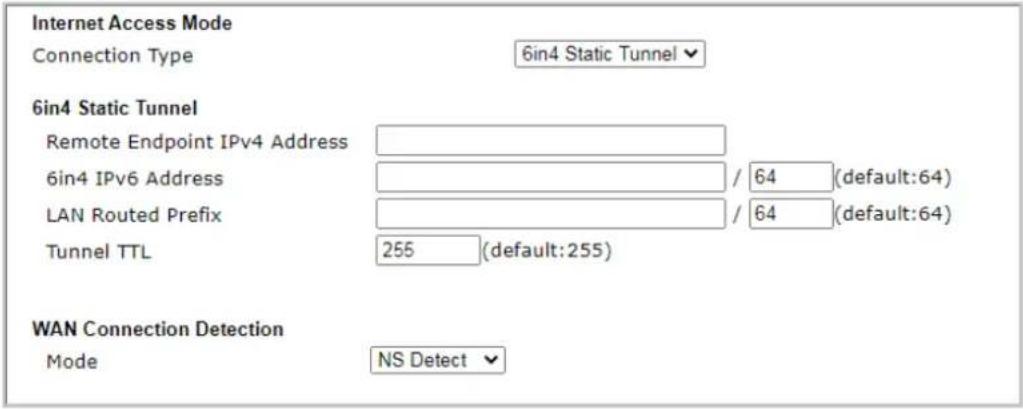
text_image
Internet Access Mode Connection Type 6in4 Static Tunnel 6in4 Static Tunnel Remote Endpoint IPv4 Address 6in4 IPv6 Address LAN Routed Prefix Tunnel TTL 255 (default:255) WAN Connection Detection Mode NS DetectOK
Available settings are explained as follows:
| Item | Description |
| Remote Endpoint IPv4 Address | Enter the static IPv4 address for the remote server. |
| 6in4 IPv6 Address Enter the | static IPv6 address for IPv4 tunnel with the value for prefix length. |
| LAN Routed Prefix Enter the | static IPv6 address for LAN routing with the value for prefix length. |
| Tunnel TTL Enter the number | er for the data lifetime in tunnel. |
| WAN Connection Detection | Such function allows you to verify whether network connection is alive or not through Ping Detect.Mode - Choose NS Detect, Always On or Ping Detect for the system to execute for WAN detection. Always On means no detection will be executed. The network connection will be on always.Ping IP/Hostname - If you choose Ping Detect as detection mode, you have to type IP address in this fieldfor pinging.●TTL (Time to Live) -If you choose Ping Detect as detection mode, you have to type TTL value. |
After finished the above settings, click OK to save the settings.
Below shows an example for successful IPv6 connection based on 6in4 Static Tunnel mode.
Online Status
| Physical Connection | System Uptime: 0day 0:4:16 | |||
| IPv4 | IPv6 | |||
| LAN Status | ||||
| IP Address | ||||
| 2001:4DD0:FF00:83E4:21D:AAFF:FE83:11B4/64 (Global) | ||||
| FE80::21D:AAFF:FE83:11B4/64 (Link) | ||||
| TX Packets | RX Packets | TX Bytes | RX Bytes | |
| 14 | 80 | 1244 | 6815 | |
| WAN1 IPv6 Status | ||||
| Enable | Mode | Up Time | ||
| Yes | 6in4 Static Tunnel | 0:04:07 | ||
| IP | Gateway IP | |||
| 2001:4DD0:FF10:83E4::2131/64 (Global) | --- | |||
| FE80::C0A8:651D/128 (Link) | ||||
| TX Packets | RX Packets | TX Bytes | RX Bytes | |
| 3 | 26 | 211 | 2302 | |
II-2-2-12 Details Page for IPv6 – 6rd
This type allows you to setup 6rd for WAN interface.
Internet Access >> IPv6
WAN 2
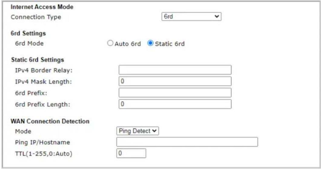
text_image
Internet Access Mode Connection Type 6rd 6rd Settings 6rd Mode Auto 6rd Static 6rd Static 6rd Settings IPv4 Border Relay: IPv4 Mask Length: 0 6rd Prefix: 6rd Prefix Length: 0 WAN Connection Detection Mode Ping Detect Ping IP/Hostname TTL(1-255,0:Auto) 0OK
Available settings are explained as follows:
| Item | Description |
| 6rd Mode Auto 6rd - Retrieve | 6rd prefix automatically from 6rd service provider. The IPv4 WAN must be set as "DHCP". Static 6rd - Set 6rd options manually. |
| IPv4 Border Relay Enter the | IPv4 addresses of the 6rd Border Relay for a given 6rd domain. |
| IPv4 Mask Length | Type a number of high-order bits that are identical across all CE IPv4 addresses within a given 6rd domain. It may be any value between 0 and 32. |
| 6rd Prefix Enter the 6rd IPv6 | address. |
| 6rd Prefix Length Enter the | IPv6 prefix length for the 6rd IPv6 prefix in number of bits. |
| WAN Connection Detection | Such function allows you to verify whether network connection is alive or not through Ping Detect. Mode - Choose NS Detect, Always On or Ping Detect for the system to execute for WAN detection. Always On means no detection will be executed. The network connection will be on always.● Ping IP/Hostname - If you choose Ping Detect as detection mode, you have to type IP address in this field for pinging.● TTL (Time to Live) -If you choose Ping Detect as detection mode, you have to type TTL value. |
After finished the above settings, click OK to save the settings.
Below shows an example for successful IPv6 connection based on 6rd mode.
Online Status
| Physical Connection | System Uptime: 0day 0:9:15 | |||
| IPv4 | IPv6 | |||
| LAN Status | ||||
| IP Address | ||||
| 2001:E41:A865:1D00:21D:AAFF:FE83:11B4/64 (Global) | ||||
| FE80::21D:AAFF:FE83:11B4/64 (Link) | ||||
| TX Packets | RX Packets | TX Bytes | RX Bytes | |
| 15 | 113 | 1354 | 18040 | |
| WAN1 IPv6 Status | ||||
| Enable | Mode | Up Time | ||
| Yes | 6rd | 0:09:06 | ||
| IP | Gateway IP | |||
| 2001:E41:A865:1D01:21D:AAFF:FE83:11B5/128(Global) | --- | |||
| FE80::C0A8:651D/128 (Link) | ||||
| TX Packets | RX Packets | TX Bytes | RX Bytes | |
| 13 | 29 | 967 | 2620 | |
II-2-3 Multi-PVC/VLAN
Multi-VLAN allows users to create profiles for specific WAN interface and bridge connections for user applications that require very high network throughput. Simply go to WAN and select Multi-VLAN.
Channel 2 has the following fixed assignment and cannot be altered.
● Channel 2: Ethernet on WAN2 (based on the model)
Channels 5 through 7 can be configured as virtual WANs (WAN5 through WAN7).
General
This page shows the basic configurations used by every channel.
WAN >> Multi-PVC/VLAN
Multi-PVC/VLAN
| General | Advanced | ||||
| Channel | Enable | WAN Type | VPI/VCI | VLAN Tag | Port-based Bridge |
| 2 | √ | Ethernet(WAN2) | None | ||
| 5. WAN5 | ☐ | Ethernet(WAN2) | None | ☐ Enable ☐ P1 ☐ P2 | |
| 6. WAN6 | ☐ | Ethernet(WAN2) | None | ☐ Enable ☐ P1 ☐ P2 | |
| 7. WAN7 | ☐ | Ethernet(WAN2) | None | ☐ Enable ☐ P1 ☐ P2 | |
Note:
Channel 3 is reserved for LTE WAN.

Available settings are explained as follows:
| Item | Description |
| Channel Display the number | of each channel. Channels 2 is used by the Internet Access web user interface and can not be configured here. Channels 5 ~ 7 are configurable. |
| Enable Display whether the | settings in this channel are enabled (Yes) or not (No). |
| WAN Type | Displays the physical medium that the channel will use. |
| VLAN Tag | Displays the VLAN tag value that will be used for the packets traveling on this channel. |
| Port-based Bridge The network | work traffic flowing on each channel will be identified by the system via their VLAN Tags. Channels using the same WAN type may not configure the same VLAN tag value. Enable - Check this box to enable the port-based bridge function on this channel. P1 ~ P2 - Check the box(es) to build bridge connection on LAN. |
To configure a PVC channel, click its channel number.
WAN links for Channel 5, 6 and 7 are provided for router-borne application such as TR-069. The settings must be applied and obtained from your ISP. For your special request, please contact with your ISP and then click WAN link of Channel 5, 6 and 7 to configure your router.
WAN >> Multi-PVC/VLAN >> Channel 5
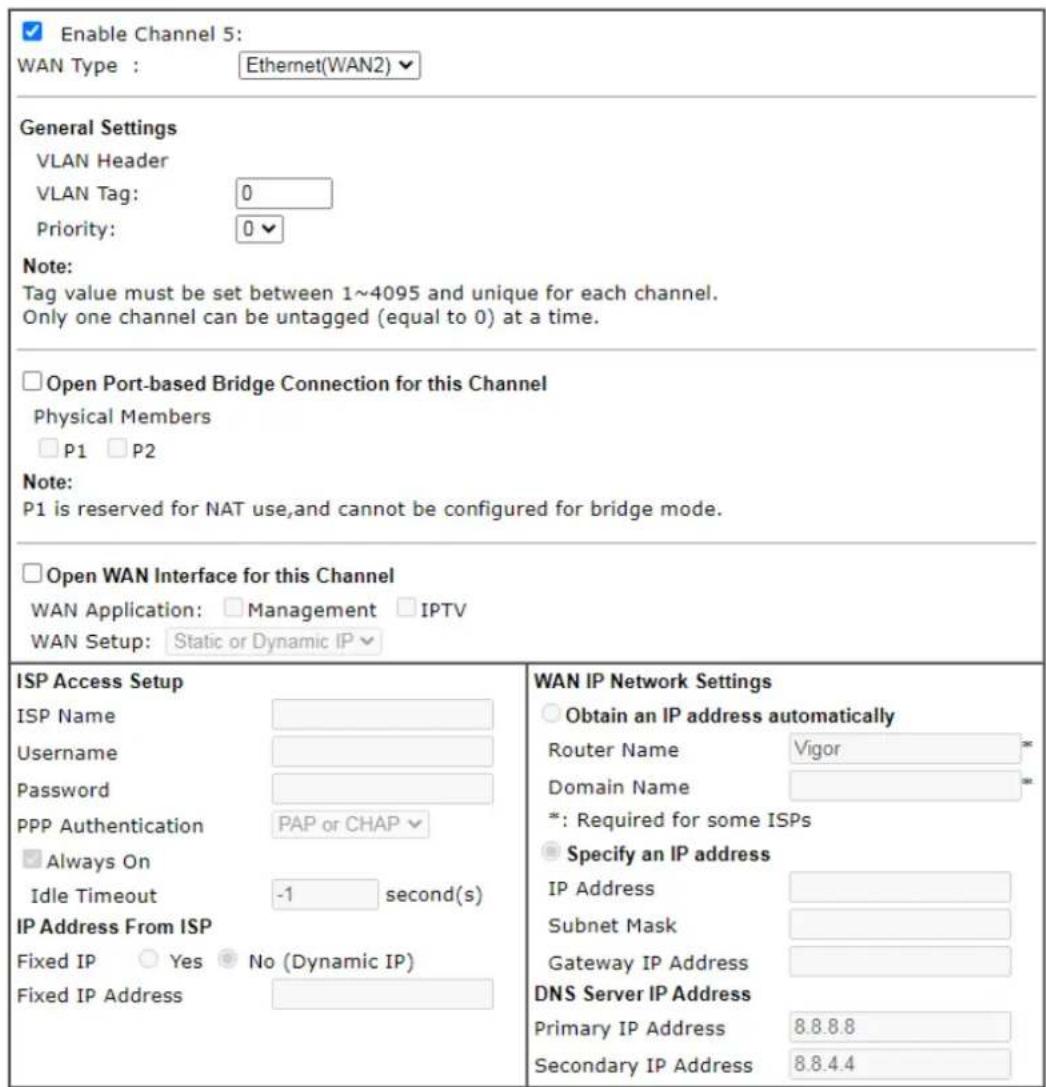
text_image
Enable Channel 5: WAN Type : Ethernet(WAN2) General Settings VLAN Header VLAN Tag: 0 Priority: 0 Note: Tag value must be set between 1~4095 and unique for each channel. Only one channel can be untagged (equal to 0) at a time. Open Port-based Bridge Connection for this Channel Physical Members P1 P2 Note: P1 is reserved for NAT use,and cannot be configured for bridge mode. Open WAN Interface for this Channel WAN Application: Management IPTV WAN Setup: Static or Dynamic IP ISP Access Setup ISP Name Username Password PPP Authentication PAP or CHAP Always On Idle Timeout -1 second(s) IP Address From ISP Fixed IP Yes No (Dynamic IP) Fixed IP Address WAN IP Network Settings Obtain an IP address automatically Router Name Vigor Domain Name *: Required for some ISPs Specify an IP address IP Address Subnet Mask Gateway IP Address DNS Server IP Address Primary IP Address 8.8.8.8 Secondary IP Address 8.8.4.4
Available settings are explained as follows:
| Item | Description |
| Enable Channel 4/5/6 | Enable - Select to enable this channel.Disable - Select to disable this channel. |
| General Settings VLAN Tag | - Enter the value as the VLAN ID number. Valid settings are in the range from 1 to 4095. The network traffic flowing on each channel will be identified by the system via their VLAN Tags. Channels using the same WAN type may not configure the same VLAN tag value.Priority - Choose the number to determine the packet priority for such VLAN. The range is from 0 to 7. |
| Open Port-based Bridge | The settings here will create a bridge between the LAN ports |
| Connection for this Channel | selected and the WAN. The WAN interface of the bridge connection will be built upon the WAN type selected using the VLAN tag configured.Physical Members- Group the physical ports by checking the corresponding check box(es) for applying the port-based bridge connection.Note: LAN port P1 is reserved for NAT use and cannot be selected for bridging. |
| Open WAN Interface for this Channel | Check the box to enable relating function.WAN ApplicationManagement can be specified for general management (Web configuration/ telnet/ TR069). If you choose Management, the configuration for this VLAN will be effective for Web configuration/ telnet/ TR069.IPTV - The IPTV configuration will allow the WAN interface to send IGMP packets to IPTV servers.WAN Setup - Choose PPPoE/PPPoA or Static or Dynamic IP to determine what WAN settings must be configured. |
| ISP Access Setup Enter your | allocated username, password and authentication parameters according to the information provided by your ISP.ISP Name - PPP Service Name. Enter if your ISP requires this setting; otherwise leave blank.Usage - Name provided by the ISP for PPPoE/ PPPoA authentication. Maximum length is 62 characters.Password - Password provided by the ISP for PPPoE/ PPPoA authentication. Maximum length is 62 characters.PPP Authentication -The protocol used for PPP authentication.PAP only- Only PAP (Password Authentication Protocol) is used.PAP or CHAP- Both PAP and CHAP (Challenge-Handshake Authentication Protocol) can be used for PPP authentication. Router negotiates with the PPTP or L2TP server to determine which protocol to use.Always On - If selected, the router will maintain the PPPoE/ PPPoA connection.Idle Timeout - Maximum length of time, in seconds, of idling allowed (no traffic) before the connection is dropped.IP Address From ISP - Specifies how the WAN IP address of the channel configured.Fixed IPYes - IP address entered in the Fixed IP Address field will be used as the IP address of the virtual WAN.No - Virtual WAN IP address will be assigned by the ISP's PPPoE/ PPPoA server. |
| WAN IP Network Settings | Obtain an IP address automatically - Select this option if the router is to receive IP configuration information from a DHCP server.Router Name - Sets the value of DHCP Option 12, which is used by some ISPs.Domain Name - Sets the value of DHCP Option 15,which is used by some ISPs.Specify an IP address - Select this option to manually enter the IP address.IP Address - Type in the IP address.Subnet Mask - Type in the subnet mask.Gateway IP Address - Type in gateway IP address.DNS Server IP Address - Type in the primary IP address for the router if you want to use Static IP mode. If necessary, type in secondary IP address for necessity in the future. |
After finished the above settings, click OK to save the settings and return to previous page.
Advanced
Such configuration is applied to upstream packets. Such information will be provided by ISP. Please contact with your ISP for detailed information.
WAN >> Multi-PVC/VLAN
Multi-PVC/VLAN
General
Advanced
| Channel | ATM QoS | PVC to PVC Binding | |||
| QoS Type | PCR | SCR | MBS | ||
| 1. | UBR ▼ | 0 | 0 | 0 | Disable ▼ |
| 5. | UBR ▼ | 0 | 0 | 0 | Disable ▼ |
| 6. | UBR ▼ | 0 | 0 | 0 | Disable ▼ |
| 7. | UBR ▼ | 0 | 0 | 0 | Disable ▼ |
Note:
- If the parameters in the ATM QoS settings are set to zero, then their default settings will be used. Also, PCR(max)=ADSL Up Speed /53/8.
- Multiple channels may use the same ADSL channel link through the PVC Binding configuration. The PVC Binding configuration is only supported for channels using ADSL, please make sure the channel that you are binding to is using ADSL as its WAN type. The binding will work only under PPPoE and MPoA 1483 Bridge mode.
- Channel 3 is reserved for LTE WAN.
OK
Cancel
Available settings are explained as follows:
| Item | Description |
| QoS Type Select a proper QoS type for the channel according to the information that your ISP provides. | |
| PCR | It represents Peak Cell Rate. The default setting is “0”. |
| SCR It represents Sustainable Cell Rate. The value of SCR must be smaller than PCR. | |
| MBS | It represents Maximum Burst Size. The range of the value is 10 to 50. |
| PVC to PVC Binding It allows the enabled PVC channel to use the same ADSL connection settings of another PVC channel. Please choose the PVC channel via the drop down list. | |
After finished the above settings, click OK to save the settings.
II-2-4 WAN Budget
This function is used to determine the data traffic volume for each WAN interface respectively to prevent overcharges for data transmission by the ISP. Please note that the Quota Limit and Billing cycle day of month settings will need to be configured correctly first in order for some period calculations to be performed correctly.
The WAN Budget feature allows you to conveniently keep track of Internet traffic volume. You can:
- set up calendar cycles to monitor;
- limit your Internet usage according to your ISP's quota;
- set up action(s) to take when the quota is exceeded.
II-2-4-1 General Setup
WAN >> WAN Budget

| General Setup | Status | ||||
| Index | Enable | Quota | When quota exceeded | Time cycle | Duration |
| WAN1 | 0MB/0MB | 0/00/00 00:00~0/00/00 00:00 | |||
| WAN2 | 0MB/0MB | 0/00/00 00:00~0/00/00 00:00 | |||
| LTE | 0MB/0MB | 0/00/00 00:00~0/00/00 00:00 | |||
Note:
-
The budget traffic information provided here is for reference only, please consult your ISP for the actual traffic usage and charges.
-
When hardware acceleration function is used, the monitored WAN traffic of Ethernet WAN interfaces may be slightly inaccurate.

| Item | Description |
| Index The WAN port. | Click to configure WAN Budget for a particular WAN. |
| Enable | v - WAN Budget is enabled on this WAN.x - WAN Budget is disabled on this WAN. |
| Quota | The current cycle's Internet usage is expressed as x/y where x is the cumulative usage and y is the upper limit. For example, 100MB/200MB means the usage thus far in this cycle is 100MB, and the upper limit is 200MB. |
| When quota exceeded Actions to be taken once the quota is reached.Shutdown - WAN will be disabled.Mail Alert - Email will be sent to the administrator. | |
| Time cycle Reset frequency of the usage data.Monthly - The Monthly option in the Criterion and Action tab was used to set up the usage quota.User Defined: The User Defined option in the Criterion and Action tab was used to set up the usage qota. | |
| Duration Start and end timestamps of the current cycle. | |
Click WAN1 (to WAN6) link to open the following web page.
WAN 1
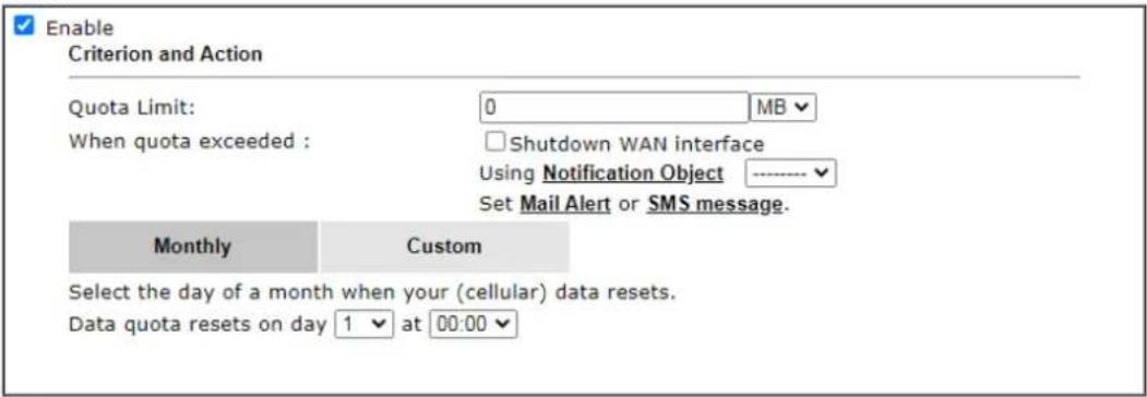
text_image
Enable Criterion and Action Quota Limit: 0 MB When quota exceeded : □ Shutdown WAN interface Using Notification Object ---- Set Mail Alert or SMS message. Monthly Custom Select the day of a month when your (cellular) data resets. Data quota resets on day 1 at 00:00Note:
- Please make sure the Time and Date of the router is configured.
- SMS message and mail will be sent when the usage reaches 95% and 100% of quota.

Available settings are explained as follows:
| Item | Description |
| Enable When selected, WAN | Budget is enabled for this WAN. |
| Quota Limit Enter the data | traffic quota allowed for such WAN interface.There are two unit (MB and GB) offered for you to specify. |
| When quota exceeded Check the box(es) as the condition(s) for the system to perform when the traffic has exceeded the budget limit.Shutdown WAN interface - All the outgoing traffic through such WAN interface will be terminated.Using Notification Object - The system will send out a notification based on the content of the notification object.Set Mail Alert - The system will send out a warning message to the administrator when the quota is running out. However, the connection charges will be calculated continuously.Set SMS message - The system will send out SMS message to the administrator when the quota is running out. | |
| Monthly Some ISP might apply for the network limitation based on the traffic limit per month. This setting is to offer a mechanism of resetting the traffic record every month.Monthly CustomSelect the day of a month when your (cellular) data resets.Data quota resets on day 1 at 00:00Data quota resets on day ... - You can determine the starting day in one month. | |
| Custom | This setting allows the user to define the billing cycle according to his request. The WAN budget will be reset with an interval of billing cycle.Monthly is default setting. If long period or a short period is required, use Custom. The period of cycle duration is between 1 day and 60 days. You can determine the cycle |
duration by specifying the days and the hours. In addition, you can specify which day of today is in a cycle.
Use Cycle in hours -
Monthly
Custom
Use Cycle in hours
○ Use Cycle in days
Usage counter resets at the beginning of each cycle.
Cycle duration : 1 ▼ days and 0 ▼ hours
Today is day 1 ▼ in the cycle.
- Cycle duration: Specify the days and hours to reset the traffic record. For example, 7 means the whole cycle is 7 days; 20 means the whole cycle is 20 days. When the time is up, the router will reset the traffic record automatically.
- Today is day – Specify the day in the cycle as the starting point which Vigor router will reset the traffic record. For example, “3” means the third day of the cycle duration.
Use Cycle in days -
Monthly
Custom
○ Use Cycle in hours
Use Cycle in days
Usage counter resets at the beginning of each cycle.
Cycle duration : 1 √ days.
Today is day 1 ▼ in the cycle and data quota resets at 00:00 ▼
- Cycle duration: Specify the days to reset the traffic record. For example, 7 means the whole cycle is 7 days; 20 means the whole cycle is 20 days. When the time is up, the router will reset the traffic record automatically.
- Today is day - Specify the day and time for data quota rest in the cycle as the starting point which Vigor router will reset the traffic record. For example, "3" means the third day of the cycle duration.
After finished the above settings, click OK to save the settings.
II-2-4-2 Status
The status page displays the status WAN budget, including the duration and the usage.
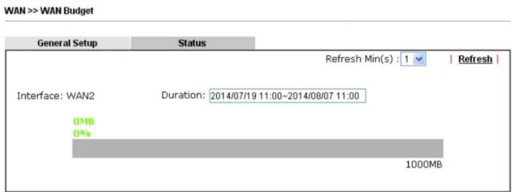
text_image
WAN >> WAN Budget General Setup Status Refresh Min(s) : 1 | Refresh | Interface: WAN2 Duration: 2014/07/19 11:00~2014/08/07 11:00 OMB 0% 1000MBIf the WAN budget is exhausted, a lock will be displayed on the page if Shutdown WAN interface is selected. Which means no data transmission will be carried out. Moreover, the system will send out a warning message to the administrator if Mail Alert is selected. Or, the system will send out SMS message to the administrator if SMS message is selected.
WAN >> WAN Budget
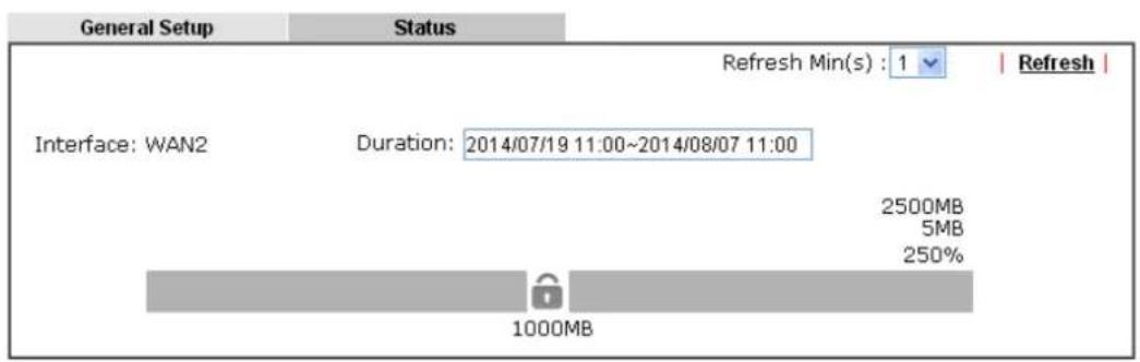
text_image
General Setup Status Refresh Min(s) : 1 | Refresh | Interface: WAN2 Duration: 2014/07/19 11:00~2014/08/07 11:00 2500MB 5MB 250% 1000MBApplication Notes
A-1 How to configure IPv6 on WAN interface?
This document is going to demonstrate how to implement an IPv6 address on Vigor Router's WAN.
- Before configuring IPv6 on WAN, please make sure the router is connected to the IPv4 Internet.
| Physical Connection | System Uptime: 0day 0:3:29 | |||
| IPv4 | IPv6 | |||
| LAN Status Primary DNS: 168.95.1.1 Secondary DNS: 168.95.192.1 | ||||
| IP Address TX Packets RX Packets | ||||
| 192.168.86.1 | 643 | 793 | ||
| WAN 1 Status >> Dial PPPoA | ||||
| Enable Line Name Mode Up Time | ||||
| Yes ADSL PPPoA 00:00:00 | ||||
| IP GW IP TX Packets TX Rate(Bps) RX Packets RX Rate(Bps) | ||||
| --- --- 0 0 0 0 | ||||
| WAN 2 Status >> Drop PPPoE | ||||
| Enable Line Name Mode Up Time | ||||
| Yes Ethernet PPPoE 0:03:20 | ||||
| IP GW IP TX Packets TX Rate(Bps) RX Packets RX Rate(Bps) | ||||
| 118.100.103.153 Tel Wt.Wt.751 79 3 81 9 | ||||
| WAN 2 Status | ||||
- Go to WAN >> Internet Access, click on IPv6 of the WAN interface that you would like to configure an IPv6 address.
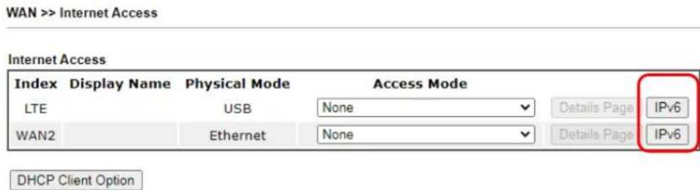
text_image
WAN >> Internet Access Internet Access Index Display Name Physical Mode Access Mode LTE USB None Details Page IPv6 WAN2 Ethernet None Details Page IPv6 DHCP Client Option- Select a Connection Type from the drop-down list, enter the required parameters. Then click OK and reboot the router to apply the settings.
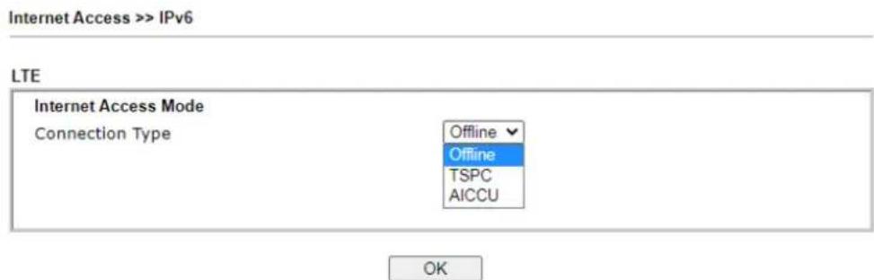
text_image
Internet Access >> IPv6 LTE Internet Access Mode Connection Type Offline Offline TSPC AICCU OK- After accomplishing the configurations, Network Administrator may check the status from the IPv6 tab on Online Status >> Physical Connection page.
| Physical Connection IPv4 | System Uptime: 0day 0:57:49 | ||
| LAN Status | |||
| IP Address | |||
| 2406::P430::F1::G41/123 (Global) | |||
| FE80::P430::F1::G41/123 (Global) | |||
| TX Packets | RX Packets | TX Bytes | RX Bytes |
| 1277 | 3060 | 182180 | 450067 |
| WAN1 IPv6 Status | |||
| Enable | Mode | Up Time | |
| No | Offline | ... | |
| IP | Gateway IP | ||
| ... | ... | ||
| WAN2 IPv6 Status | |||
| Enable | Mode | Up Time | |
| Yes | Static IPv6 | 0:57:43 | |
| IP | Gateway IP | ||
| 2406::P430::F1::G41/123 (Global) | 2406::P430::F1::G41/123 (Global) | ||
| 2406::P430::F1::G41/123 (Global) | |||
| FE80::P430::F1::G41/123 (Link) | |||
| TX Packets | RX Packets | TX Bytes | RX Bytes |
| 5180 | 2612 | 445044 | 224316 |
- Furthermore, Network Administrator may test the connectivity of IPv6 from the router by going to Diagnostics >> Ping Diagnosis and selecting "IPv6".
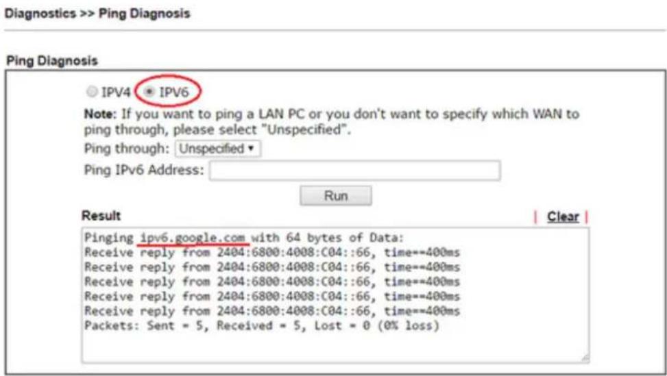
text_image
Diagnostics >> Ping Diagnosis Ping Diagnosis ○ IPv4 ● IPv6 Note: If you want to ping a LAN PC or you don't want to specify which WAN to ping through, please select "Unspecified". Ping through: Unspecified ▼ Ping IPv6 Address: Run Result | Clear | Pinging ipv6.google.com with 64 bytes of Data: Receive reply from 2404:6800:4008:C04::66, time==400ms Receive reply from 2404:6800:4008:C04::66, time==400ms Receive reply from 2404:6800:4008:C04::66, time==400ms Receive reply from 2404:6800:4008:C04::66, time==400ms Receive reply from (2404:6800:4008:C04::66, time==400ms) Packets: Sent = 5, Received = 5, Lost = 0 (0% loss)Below we will provide some examples of configuring IPv6 with different connection types.
PPP (Point-to-Point Protocol)
This applies if the IPv4 access mode is PPPoE, and the IPv4 ISP also provides an IPv6 address. To use IPv6 PPP, you just need to choose the Connection Type to "PPP", no other setting is required.
Internet Access >> IPv6
WAN 2
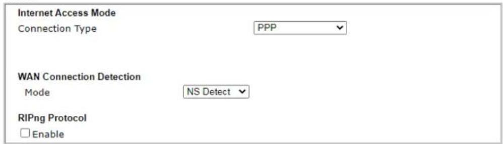
text_image
Internet Access Mode Connection Type PPP WAN Connection Detection Mode NS Detect RIPng Protocol EnableNote:
IPv4 WAN setting should be PPPoE / PPPoA client.
OK
TSPC (Tunnel Setup Protocol Client)
In this mode, the IPv6 connectivity is provided by a tunnel broker on the IPv4 Internet through a tunnel set up by Tunnel Setup Protocol (TSP). To use TSPC, you'll need to sign up for a tunnel broker service and get a username and password first, then, configure the router as follows:
- Set Connection Type to TSPC.
- Enter the Username and Password registered at the TSP server.
- Enter the IP or Domain Name of the TSPC server for Tunnel Broker.
Internet Access >> IPv6
WAN 2
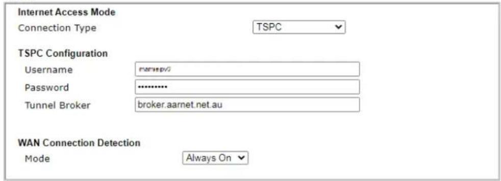
text_image
Internet Access Mode Connection Type TSPC TSPC Configuration Username naspv/ Password ****** Tunnel Broker broker.aarnet.net.au WAN Connection Detection Mode Always OnOK
Static IPv6
If your ISP provides a static IPv6 address for you, you may configure that IPv6 address for WAN by doing the following steps:
- Set Connection Type to Static IPv6.
- Enter the IPv6 address and Prefix Length which provided by the ISP, and click Add.
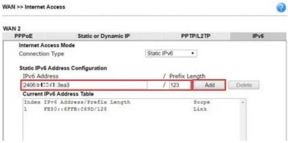
text_image
WAN >> Internet Access WAN 2 PPPoE Static or Dynamic IP PPTP/L2TP IPv6 Internet Access Mode Connection Type Static IPv6 Static IPv6 Address Configuration IPv6 Address / Prefix Length 2406±1.0/1.3ea3 / 123 Add Delete Current IPv6 Address Table Index IPv6 Address/Prefix Length Scope 1 FE80::6FFB:C69D/128 Link- You should see the IPv6 address in Current IPv6 Address Table. Then, specify the IP address of IPv6 Gateway.
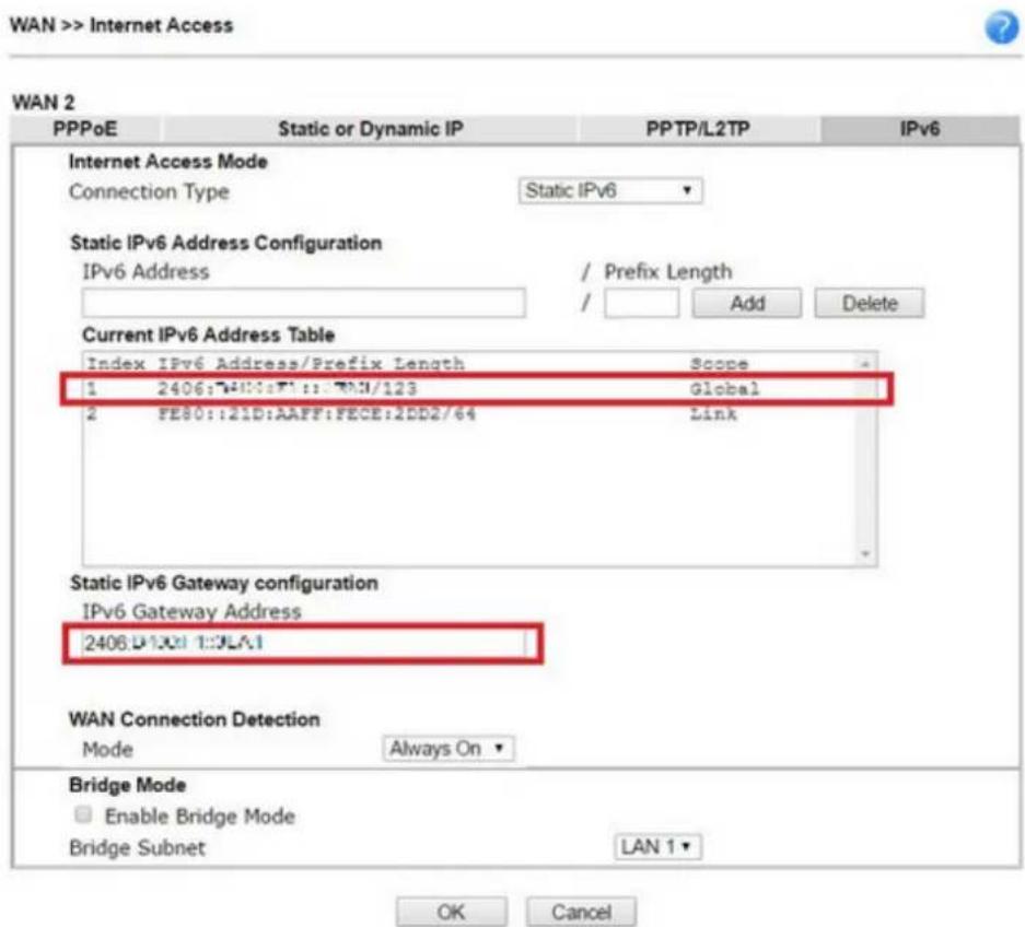
text_image
WAN >> Internet Access WAN 2 PPPoE Static or Dynamic IP PPTP/L2TP IPv6 Internet Access Mode Connection Type Static IPv6 Static IPv6 Address Configuration IPv6 Address / Prefix Length / Add Delete Current IPv6 Address Table Index IPv6 Address/Prefix Length Scope 1 2406:740::F1::750/123 Global 2 FE80::21D:AAFF:FECE:2DD2/64 Link Static IPv6 Gateway configuration IPv6 Gateway Address 2406:D130:1:DLA1 WAN Connection Detection Mode Always On Bridge Mode Enable Bridge Mode Bridge Subnet LAN 1 OK Cancel6in4 Static Tunnel
In this mode, the IPv6 connectivity is provided by a tunnel broker on the IPv4 Internet through a tunnel configured manually. To use 6in4 Static Tunnel, you need sign up for a tunnel broker service and get an IPv6 address and routed IPv6 prefixes first. Then, configure the router as follows:
- Set Connection Type to 6in4 Static Tunnel.
- Enter the tunnel server's IPv4 address in Remote Endpoint IPv4 Address.
- Enter the router's IPv6 address in 6in4 IPv6 Address.
- Enter the routed IPv6 prefix in LAN Routed Prefix.
Internet Access >> IPv6
WAN 2

text_image
Internet Access Mode Connection Type 6in4 Static Tunnel 6in4 Static Tunnel Remote Endpoint IPv4 Address no IPv4 6in4 IPv6 Address no IPv6 / 64 (default:64) LAN Routed Prefix no IPv6 / 64 (default:64) Tunnel TTL 255 (default:255) WAN Connection Detection Mode Always OnOK
II-3 LAN
Local Area Network (LAN) is a group of subnets regulated and ruled by router. The design of network structure is related to what type of public IP addresses coming from your ISP.
The most generic function of Vigor router is NAT. It creates a private subnet of your own. As mentioned previously, the router will talk to other public hosts on the Internet by using public IP address and talking to local hosts by using its private IP address. What NAT does is to translate the packets from public IP address to private IP address to forward the right packets to the right host and vice versa. Besides, Vigor router has a built-in DHCP server that assigns private IP address to each local host. See the following diagram for a briefly understanding.
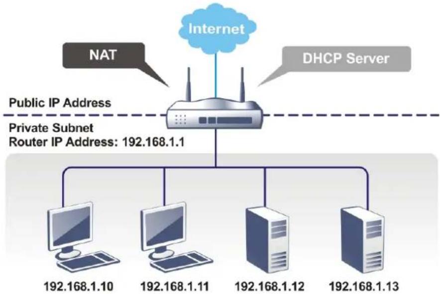
flowchart
graph TD
    A["Internet"] --> B["NAT"]
    A --> C["DHCP Server"]
    B --> D["Public IP Address"]
    C --> E["Private Subnet Router IP Address: 192.168.1.1"]
    D --> F["Computer 192.168.1.10"]
    D --> G["Computer 192.168.1.11"]
    D --> H["Computer 192.168.1.12"]
    D --> I["Computer 192.168.1.13"]
In some special case, you may have a public IP subnet from your ISP such as 220.135.240.0/24. This means that you can set up a public subnet or call second subnet that each host is equipped with a public IP address. As a part of the public subnet, the Vigor router will serve for IP routing to help hosts in the public subnet to communicate with other public hosts or servers outside. Therefore, the router should be set as the gateway for public hosts.
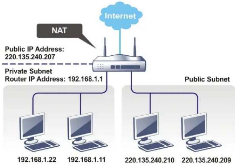
flowchart
graph TD
    A["Internet"] --> B["NAT"]
    B --> C["Router"]
    C --> D["Public Subnet"]
    C --> E["192.168.1.22"]
    C --> F["192.168.1.11"]
    C --> G["220.135.240.210"]
    C --> H["220.135.240.209"]
    I["Public IP Address: 220.135.240.207"] -.-> C
What is Routing Information Protocol (RIP)
Vigor router will exchange routing information with neighboring routers using the RIP to accomplish IP routing. This allows users to change the information of the router such as IP address and the routers will automatically inform for each other.
What is Static Route
When you have several subnets in your LAN, sometimes a more effective and quicker way for connection is the Static routes function rather than other method. You may simply set rules to forward data from one specified subnet to another specified subnet without the presence of RIP.
What are Virtual LANs and Rate Control
You can group local hosts by physical ports and create up to 8 virtual LANs. To manage the communication between different groups, please set up rules in Virtual LAN (VLAN) function and the rate of each.
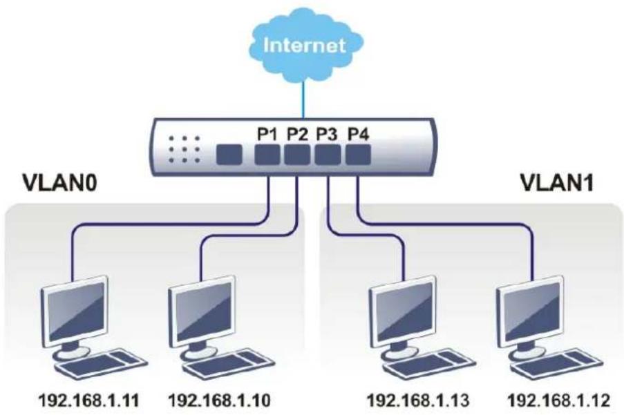
flowchart
graph TD
    A["Internet"] --> B["VLAN0"]
    A --> C["VLAN1"]
    B --> D["192.168.1.11"]
    B --> E["192.168.1.10"]
    C --> F["192.168.1.13"]
    C --> G["192.168.1.12"]
Web User Interface
A LAN comprises a collection of LAN clients, which are networked devices on your premises. A LAN client can be a computer, a printer, a Voice-over-IP (VoIP) phone, a mobile phone, a gaming console, an Internet Protocol Television (IPTV), etc, and can have either a wired (using Ethernet cabling) or wireless (using Wi-Fi) network connection.
LAN clients within the same LAN are normally able to communicate with one another directly, as they are peers to one another, unless measures, such as firewalls or VLANs, have been put in place to restrict such access. Nowadays the most common LAN firewalls are implemented on the LAN client itself. For example, Microsoft Windows since Windows XP and Apple OS X have built-in firewalls that can be configured to restrict traffic coming in and going out of the computer. VLANs, on the other hand, are usually set up using network switches or routers.
To communicate with the hosts outside of the LAN, LAN clients have to go through a network gateway, which in most cases is a router that sits between the LAN and the ISP network, which is the WAN. The router acts as a director to ensure traffic between the LAN and the WAN reach their intended destinations.
H_1(x) = 12
LAN
General Setup
VLAN
Bind IP to MAC
Routing
II-3-1 General Setup
This page provides you the general settings for LAN. Click LAN to open the LAN settings page and choose General Setup.
There are four subnets provided by the router which allow users to divide groups into different subnets (LAN1 - LAN2). In addition, different subnets can link for each other by configuring Inter-LAN Routing. At present, LAN1 setting is fixed with NAT mode only. LAN2 - LAN4 can be operated under NAT or Route mode. IP Routed Subnet can be operated under Route mode.
General Setup
| Index | Enable | DHCP | DHCPv6 | IP Address | ||
| LAN 1 | V | V | V | 192.168.1.60 | Details Page | IPv6 |
| LAN 2 | 192.168.2.1 | Details Page | IPv6 | |||
| IP Routed Subnet | 192.168.0.1 | Details Page | ||||
DHCP Server Option
Note:
Please enable LAN 2 on LAN >> VLAN page before configure them.
☐ Force router to use "DNS server IP address" settings specified in LAN1
Inter-LAN Routing
| Subnet | LAN 1 | LAN 2 |
| LAN 1 | ||
| LAN 2 |
OK
Available settings are explained as follows:
| Item | Description |
| General Setup | Allow to configure settings for each subnet respectively. Index - Display all of the LAN items. Enable- Basically, LAN1 status is enabled in default. LAN2 and IP Routed Subnet can be observed by checking the Enable box. DHCPv6- LAN1 is configured with DHCP in default. If required, please check the DHCP box for each LAN. IP Address - Display the IP address for each LAN item. Such information is set in default and you can not modify it. Details Page - Click it to access into the setting page. Each LAN will have different LAN configuration page. Each LAN must be configured in different subnet. IPv6 - Click it to access into the settings page of IPv6. |
| DHCP Server Option DHCP packets can be processed by adding option number and data information when such function is enabled. For detailed information, refer to later section. | |
| Force router to use “DNS server IP address” ..... | Force Vigor router to use DNS servers configured in LAN1/ LAN2 instead of DNS servers given by the Internet Access server (PPPoE, PPTP or DHCP server). |
| Inter-LAN Routing Check the box to link two or more different subnets (LAN and LAN). Inter-LAN Routing allows different LAN subnets to be interconnected or isolated. It is only available when the VLAN functionality is enabled. Refer to section II-2-2 VLAN on how to set up VLANs. In the Inter-LAN Routing matrix, a selected checkbox means that the 2 intersecting LANs can communicate with each other. | |
When you finish the configuration, please click OK to save and exit this page.
II-3-1-1 Details Page for LAN1 = Ethernet TCP/IP and DHCP Setup
There are two configuration pages for LAN1, Ethernet TCP/IP and DHCP Setup (based on IPv4) and IPv6 Setup. Click the tab for each type and refer to the following explanations for detailed information.
LAN >> General Setup
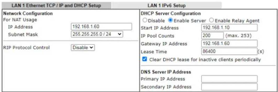
text_image
LAN 1 Ethernet TCP / IP and DHCP Setup LAN 1 IPv6 Setup Network Configuration For NAT Usage IP Address 192.168.1.60 Subnet Mask 255.255.255.0 / 24 RIP Protocol Control Disable DHCP Server Configuration Disable Enable Server Enable Relay Agent Start IP Address 192.168.1.10 IP Pool Counts 200 (max. 253) Gateway IP Address 192.168.1.60 Lease Time 86400 (s) Clear DHCP lease for inactive clients periodically DNS Server IP Address Primary IP Address Secondary IP AddressOK
Available settings are explained as follows:
| Item | Description |
| Network Configuration For | NAT Usage,IP Address- This is the IP address of the router. (Default: 192.168.1.1).Subnet Mask- The subnet mask, together with the IP Address field, indicates the maximum number of clients allowed on the subnet. (Default: 255.255.255.0/ 24).RIP Protocol Control,Enable- When Enabled, the router will attempt to exchange routing information with neighbouring routers using the Routing Information Protocol. |
| DHCP ServerConfiguration | DHCP stands for Dynamic Host Configuration Protocol. The router by factory default acts a DHCP server for your network so it automatically dispatches related IP settings to any local user configured as a DHCP client. It is highly recommended that you leave the router enabled as a DHCP server if you do not have a DHCP server for your network.If you want to use another DHCP server in the network other than the Vigor Router's, you can let Relay Agent help you to redirect the DHCP request to the specified location.Disable- Let you manually assign IP address to every host in the LAN.Enable Server- Let the router assign IP address to every host in the LAN.Start IP Address- The beginning LAN IP address that is given out to LAN DHCP clients.IP Pool Counts- The maximum number of IP addresses to be handed out by DHCP. The default value is 200.Valid range is between 1 and 253. The actual number of IP addresses available for assignment is the IP Pool Counts, or 253 minus the last octet of the Start IP Address, whichever is smaller.Gateway IP Address- The IP address of the gateway, which is the host on the LAN that relays all traffic coming into and going out of the LAN. The gateway is normally the router, and therefore the Gateway IP Address should be identical to the IP Address in the Network Configurationsection above.Lease Time- The maximum duration DHCP-issued IP addresses can be used before they have to be renewed.Clear DHCP lease for inactive clients periodically- If selected, the router sends ARP requests recycles IP addresses previously assigned to inactive DHCP clients to prevent exhaustion of the IP address pool.Note:When Clear DHCP lease for inactive clients periodically is enabled, router will do the following:Check activities of DHCP clients by ARP requests every minute when the available DHCP IP addresses are less than 30Clear DHCP lease when the client is not responding ARP replies.Enable Relay Agent- When selected, all DHCP requests are forwarded to a DHCP server outside of the LAN subnet, and whose address is specified in the DHCP Server IP Address field.DHCP Server IP Address- It is available when Enable Relay Agentis checked. Set the IP address of the DHCP server you are going to use so the Relay Agent can help to forward the DHCP request to the DHCP server. |
| DNS Server IP AddressDNS | stands for Domain Name System. Every Internet host must have a unique IP address, also they may have a human-friendly, easy to remember name such as www.yahoo.com. The DNS server converts the user-friendly name into its equivalent IP address.Primary IP Address-You must specify a DNS server IP address here because your ISP should provide you with usually more than one DNS Server.Secondary IP Address- You can specify secondary DNS server IP address here because your ISP often provides you more than one DNS Server.The default DNS Server IP address can be found via Online Status:Online StatusPhysical ConnectionIPv4IPv6System Uptime: 22:22:45LAN Status Primary DNS: 8.8.8.8 Secondary DNS: 8.8.4.4IP Address TX Packets RX Packets192.168.1.1 0 41533If both the Primary IP and Secondary IP Address fields are left empty, the router will assign its own IP address to local users as a DNS proxy server and maintain a DNS cache.If the IP address of a domain name is already in the DNS cache, the router will resolve the domain name immediately. Otherwise, the router forwards the DNS query packet to the external DNS server by establishing a WAN (e.g. DSL/ Cable)connection. |
When you finish the configuration, please click OK to save and exit this page.
Private IP addresses can be assigned automatically to LAN clients using Dynamic Host Configuration Protocol (DHCP), or manually assigned. The DHCP server can either be the router (the most common case), or a separate server, that hands out IP addresses to DHCP clients.
Alternatively, static IP addresses can be manually configured on LAN clients as part of their network settings. No matter how IP addresses are configured, it is important that no two devices get the same IP address. If both DHCP and static assignment are used on a network, it is important to exclude the static IP addresses from the DHCP IP pool. For example, if your LAN uses the 192.168.1.x subnet and you have 20 DHCP clients and 20 static IP clients, you could configure 192.168.1.10 as the Start IP Address, 50 as the IP Pool Counts (enough for the current number of DHCP clients, plus room for future expansion), and use addresses greater than 192.168.1.100 for static assignment.
II-3-1-2 Details Page for LAN2
LAN >> General Setup
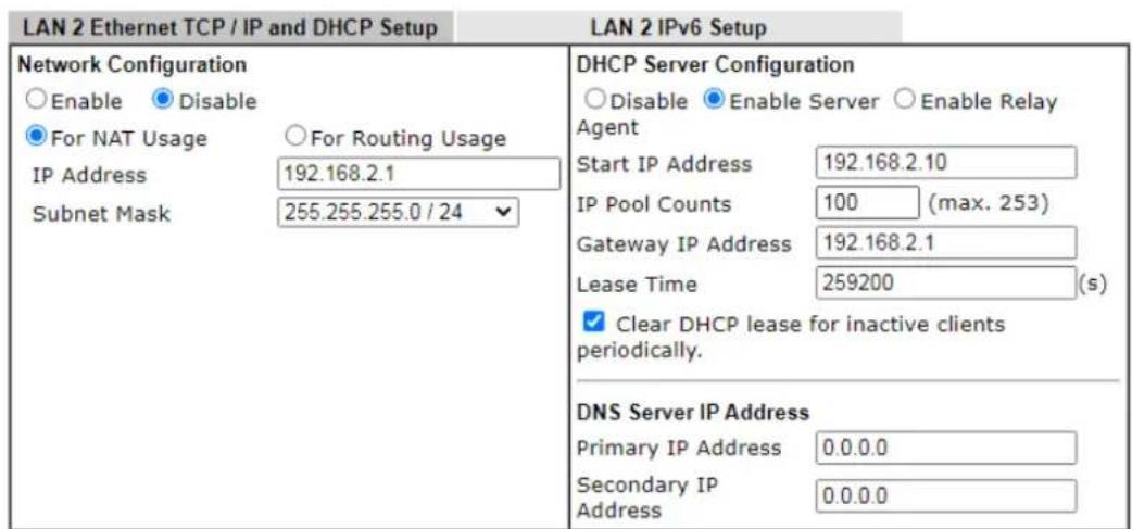
text_image
LAN 2 Ethernet TCP / IP and DHCP Setup LAN 2 IPv6 Setup Network Configuration Enable Disable For NAT Usage For Routing Usage IP Address 192.168.2.1 Subnet Mask 255.255.255.0 / 24 DHCP Server Configuration Disable Enable Server Enable Relay Agent Start IP Address 192.168.2.10 IP Pool Counts 100 (max. 253) Gateway IP Address 192.168.2.1 Lease Time 259200 (s) Clear DHCP lease for inactive clients periodically. DNS Server IP Address Primary IP Address 0.0.0.0 Secondary IP Address 0.0.0.0OK
Available settings are explained as follows:
| Item | Description | ||
| Network Configuration | Enable/Disable - Click Enable to enable such configuration; click Disable to disable such configuration.For NAT Usage - Click this radio button to invoke NAT function.For Routing Usage - Click this radio button to invoke this function.IP Address - This is the IP address of the router. (Default: 192.168.1.1).Subnet Mask - The subnet mask, together with the IP Address field, indicates the maximum number of clients allowed on the subnet. (Default: 255.255.255.0/ 24). | ||
| DHCP Server Configuration | DHCP stands for Dynamic Host Configuration Protocol. The router by factory default acts a DHCP server for your network so it automatically dispatch related IP settings to any local user configured as a DHCP client. It is highly recommendedthat you leave the router enabled as a DHCP server if you do not have a DHCP server for your network.Disable Server - Let you manually assign IP address to every host in the LAN.Enable Server - Let the router assign IP address to every host in the LAN.Start IP Address - The beginning LAN IP address that is given out to LAN DHCP clients.IP Pool Counts - The maximum number of IP addresses to be handed out by DHCP. The default value is 100. Valid range is between 1 and 253. The actual number of IP addresses available for assignment is the IP Pool Counts, or 253 minus the last octet of the Start IP Address, whichever is smaller.Gateway IP Address - The IP address of the gateway, which is the host on the LAN that relays all traffic coming into and going out of the LAN. The gateway is normally the router, and therefore the Gateway IP Address should be identical to the IP Address in the Network Configuration section above.Lease Time - The maximum duration DHCP-issued IP addresses can be used before they have to be renewed.Clear DHCP lease for inactive clients periodically - If selected, the router sends ARP requests recycles IP addresses previously assigned to inactive DHCP clients to prevent exhaustion of the IP address pool.Note: When Clear DHCP lease for inactive clients periodically is enabled, router will do the following:Check activities of DHCP clients by ARP requests every minute when the available DHCP IP addresses are less than 30Clear DHCP lease when the client is not responding ARP replies. Enable Relay Agent - When selected, all DHCP requests are forwarded to a DHCP server outside of the LAN subnet, and whose address is specified in the DHCP Server IP Address field.DHCP Server IP Address - It is available when Enable Relay Agent is checked. Set the IP address of the DHCP server you are going to use so the Relay Agent can help to forward the DHCP request to the DHCP server. | ||
| DNS Server IP Address DNS | stands for Domain Name System. Every Internet host must have a unique IP address, also they may have a human-friendly, easy to remember name such as www.yahoo.com. The DNS server converts the user-friendly name into its equivalent IP address.Primary IP Address -You must specify a DNS server IP address here because your ISP should provide you with usually more than one DNS Server.Secondary IP Address - You can specify secondary DNS server IP address here because your ISP often provides you more than one DNS Server.The default DNS Server IP address can be found via Online Status: | ||
| Online Status | |||
| Physical Connection | System Updime: 22:22:45 | ||
| IPv4 | IPv6 | ||
| LAN Status | Primary DNS: 8.6.8.8 | Secondary DNS: 8.6.4.4 | |
| IP Address | TX Packets | RX Packets | |
| 192 168.1.1 | 0 | 41533 | |
| If both the Primary IP and Secondary IP Address fields are left empty, the router will assign its own IP address to local users as a DNS proxy server and maintain a DNS cache.If the IP address of a domain name is already in the DNS cache, the router will resolve the domain name immediately. Otherwise, the router forwards the DNS query packet to the external DNS server by establishing a WAN (e.g. DSL/ Cable) connection. | |||
When you finish the configuration, please click OK to save and exit this page.
II-3-1-3 Details Page for IP Routed Subnet
LAN >> General Setup
TCP/IP and DHCP Setup for IP Routed Subnet
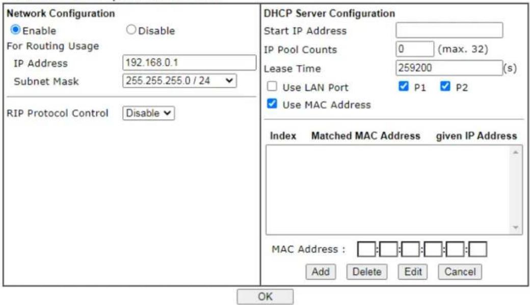
text_image
Network Configuration Enable For Routing Usage IP Address 192.168.0.1 Subnet Mask 255.255.255.0 / 24 RIP Protocol Control Disable DHCP Server Configuration Start IP Address IP Pool Counts 0 (max. 32) Lease Time 259200 (s) Use LAN Port P1 P2 Use MAC Address Index Matched MAC Address given IP Address MAC Address : Add Delete Edit Cancel OKAvailable settings are explained as follows:
| Item | Description |
| Network Configuration | Enable/Disable - Click Enable to enable such configuration; click Disable to disable such configuration.For Routing Usage,IP Address - This is the IP address of the router. (Default: 192.168.1.1).Subnet Mask - The subnet mask, together with the IP Address field, indicates the maximum number of clients allowed on the subnet. (Default: 255.255.255.0/ 24).RIP Protocol Control,Enable - When Enabled, the router will attempt to exchange routing information with neighbouring routers using theRouting Information Protocol. |
| DHCP ServerConfiguration | DHCP stands for Dynamic Host Configuration Protocol. The router by factory default acts a DHCP server for your network so it automatically dispatch related IP settings to any local user configured as a DHCP client. It is highly recommended that you leave the router enabled as a DHCP server if you do not have a DHCP server for your network.If you want to use another DHCP server in the network other than the Vigor Router's, you can let Relay Agent help you to redirect the DHCP request to the specified location.Start IP Address - The beginning LAN IP address that is given out to LAN DHCP clients.IP Pool Counts - The maximum number of IP addresses to be handed out by DHCP. The default value is 100. Valid range is between 1 and 253. The actual number of IP addresses available for assignment is the IP Pool Counts, or 253 minus the last octet of the Start IP Address, whichever is smaller.Lease Time - The maximum duration DHCP-issued IP addresses can be used before they have to be renewed.Use LAN Port - Specify an IP for IP Route Subnet. If it is enabled, DHCP server will assign IP address automatically for the clients coming from P1 and/ or P2. Please check the box of P1 and P2.Use MAC Address - Check such box to specify MAC address.MAC Address: Enter the MAC Address of the host one by one and click Add to create a list of hosts which can be assigned, deleted or edited from above pool. Set a list of MAC Address for 2^nd DHCP server will help router to assign the correct IP address of the correct subnet to the correct host. So those hosts in 2^nd subnet won't get an IP address belonging to 1^st subnet.Add - Enter the MAC address in the boxes and click this button to add.Delete - Click it to delete the selected MAC address.Edit - Click it to edit the selected MAC address.Cancel - Click it to cancel the job of adding, deleting and editing. |
When you finish the configuration, please click OK to save and exit this page.
II-3-1-4 Details Page for LAN IPv6 Setup
There are two configuration pages for each LAN. Click the tab for each type and refer to the following explanations for detailed information. Below shows the settings page for IPv6.
LAN >> General Setup
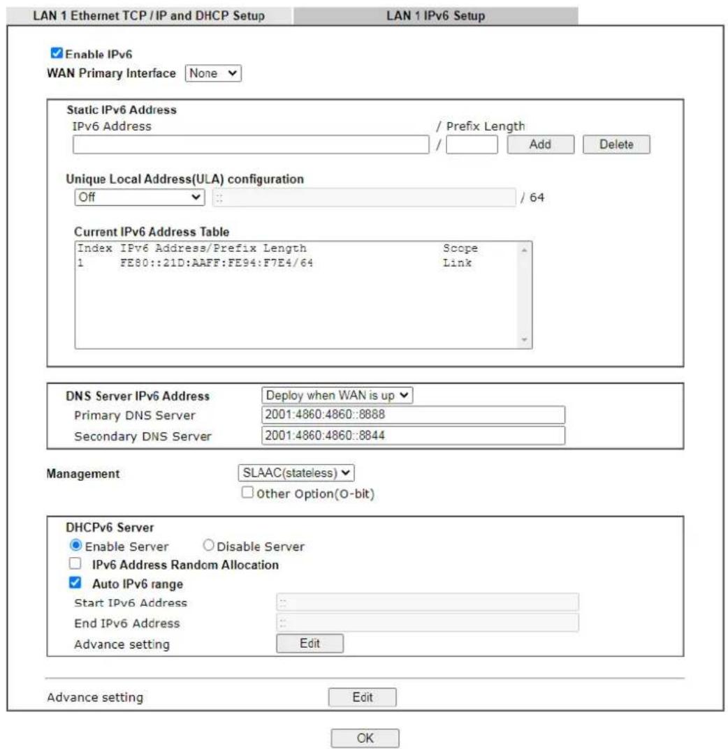
text_image
LAN 1 Ethernet TCP / IP and DHCP Setup LAN 1 IPv6 Setup Enable IPv6 WAN Primary Interface None Static IPv6 Address IPv6 Address / Prefix Length Add Delete Unique Local Address(ULA) configuration Off : : / 64 Current IPv6 Address Table Index IPv6 Address/Prefix Length Scope 1 FE80::21D:AAFF:FE94:F7E4/64 Link DNS Server IPv6 Address Deploy when WAN is up Primary DNS Server 2001:4860:4860::8888 Secondary DNS Server 2001:4860:4860::8844 Management SLAAC(stateless) Other Option(O-bit) DHCPv6 Server Enable Server Disable Server IPv6 Address Random Allocation Auto IPv6 range Start IPv6 Address : End IPv6 Address : Advance setting Edit Advance setting Edit OKIt provides 2 daemons for LAN side IPv6 address configuration. One is SLAAC(stateless) and the other is DHCPv6 (Stateful) server.
Available settings are explained as follows:
| Item | Description |
| Enable IPv6 Check the box to enable the configuration of LAN 1 IPv6 Setup. | |
| WAN Primary Interface | Use the drop down list to specify a WAN interface for IPv6. |
| Static IPv6 Address IPv6 Address -Type static IPv6 address for LANPrefix Length - Enter the fixed value for prefix length.Add - Click it to add a new entry.Delete - Click it to remove an existed entry. | |
| Unique Local Address (ULA) configuration | Unique Local Addresses (ULAs) are private IPv6 addresses assigned to LAN clients.Off - ULA is disabled.Manually ULA Prefix - LAN clients will be assigned ULAs generated based on the prefix manually entered.Auto ULA Prefix - LAN clients will be assigned ULAs using an automatically-determined prefix. |
| Current IPv6 Address Table | Display current used IPv6 addresses. |
| DNS Server IPv6 Address Deploy when WAN is up - The RA (router advertisement) packets will be sent to LAN PC with DNS server information only when network connection by any one of WAN interfaces is up.Enable - The RA (router advertisement) packets will be sent to LAN PC with DNS server information no matter WAN connection is up or not.Primary DNS Sever - Enter the IPv6 address for Primary DNS server.Secondary DNS Server -Type another IPv6 address for DNS server if required.Disable - DNS server will not be used. | |
| Management | Configures the Managed Address Configuration flag (M-bit) in Route Advertisements.Off - No configuration information is sent using Route Advertisements.SLAAC(stateless) - M-bit is unset.DHCPv6(stateful) - M-bit is set, which indicates to LAN clients that they should acquire all IPv6 configuration information from a DHCPv6 server. The DHCPv6 server can either be the one built into the Vigor2860, or a separate DHCPv6 server. |
| Other Option(O-bit) | When selected, the Other Configuration flag is set, which indicates to LAN clients that IPv6 configuration information besides LAN IPv6 addresses is available from a DHCPv6 server.Setting the M-bit (see Management above) has the same effect as implicitly setting the O-bit, as DHCPv6 supplies all IPv6 configuration information, including what is indicated as available when the O-bit is set. |
| DHCPv6 Server Enable Server -Click it to enable DHCPv6 server. DHCPv6Server could assign IPv6 address to PC according to the Start/ End IPv6 address configuration.Disable Server -Click it to disable DHCPv6 server.IPv6 Address Random Allocation -Auto IPv6 range - After check the box, Vigor router will assign the IPv6 range automatically.Start IPv6 Address / End IPv6 Address -Enter the start and end address for IPv6 server.Advance setting - Click the Edit button to configure advanced IPv6 settings for DHCPv6 server. | |
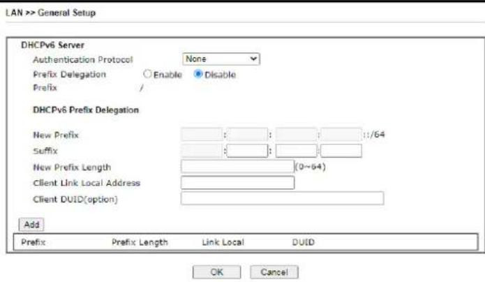
text_image
LAN >> General Setup DHCPv6 Server Authentication Protocol None Prefix Delegation Enable Disable Prefix / DHCPv6 Prefix Delegation New Prefix : : : : : :1/64 Suffix : : : New Prefix Length (0~64) Client Link Local Address Client DUID(option) Add Prefix Prefix Length Link Local DUID OK CancelAdvance setting The Advanced Settings page has additional settings for Router Advertisement and enabling multiple WANs for IPv6 traffic.
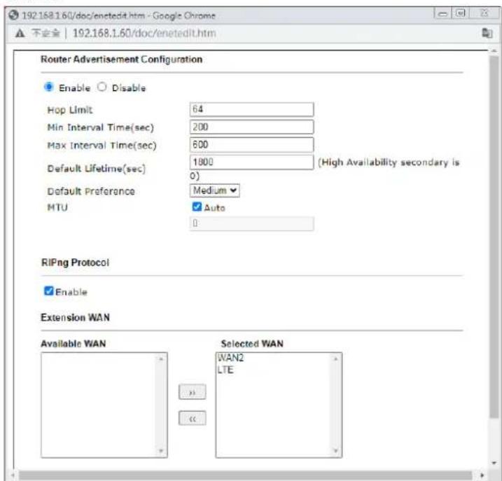
text_image
192.168.1.60/doc/enetedit.htm - Google Chrome 安全 | 192.168.1.60/doc/enetedit.htm Router Advertisement Configuration Enable Disable Hop Limit 64 Min Interval Time(sec) 200 Max Interval Time(sec) 600 Default Lifetime(sec) 1800 (High Availability secondary is 0) Default Preference Medium MTU ✓ Auto 0 RIPng Protocol ✓ Enable Extension WAN Available WAN Selected WAN WAN2 LTERouter Advertisement Configuration - Click Enable to enable router advertisement server. The router advertisement daemon sends Router Advertisement messages, specified by RFC 2461, to a local Ethernet LAN periodically and when requested by a node sending a Router Solicitation message. These messages are required for IPv6 stateless auto-configuration.
Disable - Click it to disable router advertisement server.
Hop Limt - The value is required for the device behind the router when IPv6 is in use.
Min/Max Interval Time (sec) - It defines the interval (between minimum time and maximum time) for sending RA (Router Advertisement) packets.
Default Lifetime (sec) -Within such period of time, VigorLTE 200 can be treated as the default gateway.
Default Preference - It determines the priority of the host behind the router when RA (Router Advertisement) packets are transmitted.
MTU - It means Max Transmit Unit for packet. If Auto is
| selected, the router will determine the MTU value for LAN.RIPng Protocol -RIPng (RIP next generation) offers the same functions and benefits as IPv4 RIP v2.Extension WAN – In addition to the default WAN used for IPv6 traffic specified in the WAN Primary Interface in the LAN IPv6 Setup page, additional WANs can be selected to carry IPv6 traffic by enabling them in the Extension WAN section.Available WAN – Additional WANs available but not currently selected to carry IPv6 traffic.Selected WAN – Additional WANs selected to carry IPv6 traffic. |
After making changes on the Advance setting page, click the OK button to retain the changes and return to the LAN IPv6 Setup page. Be sure to click OK on the LAN IPv6 Setup page or else changes made on the Advance setting page will not be saved.
II-3-1-5 DHCP Server Options
DHCP Options can be configured by clicking the Advanced button on the LAN General Setup screen.
LAN >> General Setup
DHCP Server Customized Status
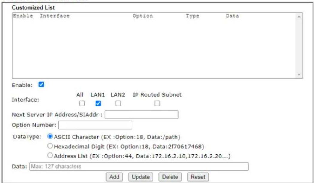
text_image
Customized List Enable Interface Option Type Data Enable: ✓ Interface: All LAN1 LAN2 IP Routed Subnet Next Server IP Address/SIAddr : Option Number: DataType: ASCII Character (EX :Option:18, Data:/path) Hexadecimal Digit (EX: Option:18, Data:2f70617468) Address List (EX :Option:44, Data:172.16.2.10,172.16.2.20...) Data: Max: 127 characters Add Update Delete ResetNote:
-
Configuring options 44, 46 or 66 here will overwrite the settings by telnet command "msubnet".
-
Configuring option 3 here will overwrite the setting in "LAN >> General Setup" Details Page's "Gateway IP Address" field.
-
Configuring option 15 here will overwrite the setting in "WAN >> Internet Access >> Static or Dynamic IP" Detail Page's "Domain Name" field.
OK
Available settings are explained as follows:
| Item | Description |
| Customized List Shows all the DHCP options that have been configured in the system. | |
| Enable If selected, DHCP option entry is enabled.If unselected, DHCP option entry is disabled. | |
| Interface LAN interface(s) to which this entry is applicable. | |
| Next Server IP Address/SIAddr | Overrides the DHCP Next Server IP address (DHCP Option 66) supplied by the DHCP server. |
| Option Number DHCP option number (e.g., 100). | |
| DataType Type of data in the Data field:ASCII Character - A text string. Example: / path.Hexadecimal Digit - A hexadecimal string. Valid characters are from 0 to 9 and from a to f. Example: 2f70617468.Address List - One or more IPv4 addresses, delimited by commas. | |
| Data Data of this DHCP option. | |
To add a DHCP option entry from scratch, clear the data entry fields (Enable, Interface, Option Number, DataType and Data) by clicking Reset. After filling in the values, click Add to create the new entry.
To add a DHCP option entry modeled after an existing entry, click the model entry in Customized List. The data entry fields will be populated with values from the model entry. After making all necessary changes for the new entry, click Add to create it.
To modify an existing DHCP option entry, click on it in Customized List. The data entry fields will be populated with the current values from the entry. After making all necessary changes, click Update to save the changes.
To delete a DHCP option entry, click on it in Customized List, and then click Delete.
II-3-2 VLAN
Virtual Local Area Networks (VLANs) allow you to subdivide your LAN to facilitate management or to improve network security.
Select LAN>>VLAN from the menu bar of the Web UI to bring up the VLAN Configuration page.
Tagged VLAN
The tagged VLANs (802.1q) can mark data with a VLAN identifier. This identifier can be carried through an onward Ethernet switch to specific ports. The specific VLAN clients can also pick up this identifier as it is just passed to the LAN. You can set the priorities for LAN-side QoS. You can assign each of VLANs to each of the different IP subnets that the router may also be operating, to provide even more isolation. The said functionality is tag-based multi-subnet.
Port-Based VLAN
Relative to tag-based VLAN which groups clients with an identifier, port-based VLAN uses physical ports (P1 \~ P2) to separate the clients into different VLAN group.
Virtual LAN function provides you a very convenient way to manage hosts by grouping them based on the physical port. The multi-subnet can let a small businesses have much better isolation for multi-occupancy applications. Go to LAN page and select VLAN. The following page will appear. Click Enable to invoke VLAN function.
Below is an example page in VigorLTE 200Ln:
LAN >> VLAN Configuration
VLAN Configuration
- For each VLAN row, selecting Enable VLAN Tag will apply the associated VID to the selected wired LAN port.
- Wireless LAN traffic is always untagged, but the SSID is still a member of the selected VLAN (group).
- Each VID must be unique.


Info
Settings in this page only applied to LAN port but not WAN port.
Available settings are explained as follows:
| Item | Description |
| Enable Click it to enable VLAN configuration. | |
| LAN P1 - P2- Check the LAN port(s) to group them under the selected VLAN. | |
| Wireless LAN SSID1 - SSID4 - | Check the SSID boxes to group them under the selected VLAN. |
| Subnet Choose one of them | to make the selected VLAN mapping to the specified subnet only. For example, LAN1 is specified for VLAN0. It means that PCs grouped under VLAN0 can get the IP address(es) that specified by the subnet. |
| VLAN Tag | Enable - Check the box to enable the function of VLAN with tag.The router will add specific VLAN number to all packets on the LAN while sending them out.Please Enter the tag value and specify the priority for the packets sending by LAN.VID - Enter the value as the VLAN ID number. The range is form 0 to 4095. VIDs must be unique.Priority - Valid values are from 0 to 7, where 1 has the lowest priority, followed by 0, and finally from 2 to 7 in increasing order of priority. |

Info
Leave one VLAN untagged at least to prevent from not connecting to Vigor router due to unexpected error.
The Vigor router supports up to 8 VLANs. Each VLAN can be set up to use one or more of the Ethernet ports and wireless LAN Service Set Identifiers (SSIDs). Within the grid of VLANs (horizontal rows) and LAN interfaces (vertical columns),
● all hosts within the same VLAN (horizontal row) are visible to one another
- all hosts connected to the same LAN or WLAN interface (vertical column) are visible to one another if
- they belong to the same VLAN, or
- they belong to different VLANs, and inter-LAN routing (LAN>>General Setup) between them is enabled (see below).
☐ Force router to use "DNS server IP address" settings specified in LAN1 Inter-LAN Routing
| Subnet | LAN 1 | LAN 2 |
| LAN 1 | ||
| LAN 2 |
OK
Inter-LAN Routing allows different LAN subnets to be interconnected or isolated. It is only available when the VLAN functionality is enabled. In the Inter-LAN Routing matrix, a selected checkbox means that the 2 intersecting LANs can communicate with each other.
VigorLTE 200 series features a hugely flexible VLAN system. In its simplest form, each of the Gigabit LAN ports can be isolated from each other, for example to feed different companies or departments but keeping their local traffic completely separated.
Configuring port-based VLAN for wireless and non-wireless clients
-
All the wire network clients are categorized to group VLAN0 in subnet 192.168.1.0/24 (LAN1).
-
All the wireless network clients are categorized to group VLAN1 in subnet 192.168.2.0/24 (LAN2).
-
Open LAN>>VLAN. Check the boxes according to the statement in step 1 and Step 2.
LAN >> VLAN Configuration
VLAN Configuration
| ✓ Enable | LAN | Wireless LAN | Subnet | VLAN Tag | ||||||
| P1 | P2 | SSID1 | SSID2 | SSID3 | SSID4 | Enable | VID | Priority | ||
| VLAN0 | ✓ | ☐ | ✓ | ✓ | ☐ | ☐ | LAN 1 ✓ | ☐ | 0 | 0 ✓ |
| VLAN1 | ✓ | ☐ | ✓ | ✓ | ✓ | ✓ | LAN 2 ✓ | ☐ | 0 | 0 ✓ |
| VLAN2 | ☐ | ☐ | ☐ | ☐ | ☐ | ☐ | LAN 1 ✓ | ☐ | 0 | 0 ✓ |
| VLAN3 | ☐ | ☐ | ☐ | ☐ | ☐ | ☐ | LAN 1 ✓ | ☐ | 0 | 0 ✓ |
| VLAN4 | ☐ | ☐ | ☐ | ☐ | ☐ | ☐ | LAN 1 ✓ | ☐ | 0 | 0 ✓ |
| VLAN5 | ☐ | ☐ | ☐ | ☐ | ☐ | ☐ | LAN 1 ✓ | ☐ | 0 | 0 ✓ |
| VLAN6 | ☐ | ☐ | ☐ | ☐ | ☐ | ☐ | LAN 1 ✓ | ☐ | 0 | 0 ✓ |
| VLAN7 | ☐ | ☐ | ☐ | ☐ | ☐ | ☐ | LAN 1 ✓ | ☐ | 0 | 0 ✓ |
Note:
- For each VLAN row, selecting Enable VLAN Tag will apply the associated VID to the selected wired LAN port.
- Wireless LAN traffic is always untagged, but the SSID is still a member of the selected VLAN (group).
- Each VID must be unique.
OK Clear Cancel
- Click OK.
- Open LAN>>General Setup. If you want to let the clients in both groups communicate with each other, simply activate Inter-LAN Routing by checking the box between LAN1 and LAN2.
LAN >> General Setup
General Setup
| Index | Enable | DHCP | DHCPv6 | IP Address | ||
| LAN 1 | V | V | V | 192.168.1.60 | Details Page | IPv6 |
| LAN 2 | □ | ☑ | ☑ | 192.168.2.1 | Details Page | IPv6 |
| IP Routed Subnet | □ | ☑ | 192.168.0.1 | Details Page | ||
DHCP Server Option
Note:
Please enable LAN 2 on LAN >> VLAN page before configure them.
☐ Force router to use "DNS server IP address" settings specified in LAN1 Inter-LAN Routing
| Subnet | LAN 1 | LAN 2 |
| LAN 1 | ||
| LAN 2 |
OK
Vigor router supports up to six private IP subnets on LAN. Each can be independent (isolated) or common (able to communicate with each other). This is ideal for departmental or multi-occupancy applications.

Info
As for the VLAN applications, refer to "Appendix I: VLAN Application on Vigor Router" for more detailed information.
II-3-3 Bind IP to MAC
This function is used to bind the IP and MAC address in LAN to have a strengthening control in network. With the Bind IP to MAC feature you can reserve LAN IP addresses for LAN clients. Each reserved IP address is associated with a Media Access Control (MAC) address.
Click LAN and click Bind IP to MAC to open the setup page.
Bind IP to MAC
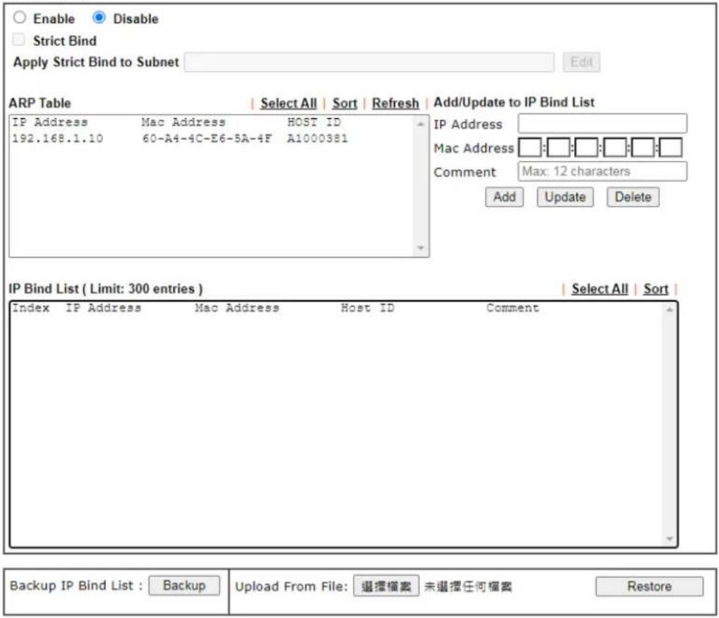
text_image
Enable Disable Strict Bind Apply Strict Bind to Subnet Edit ARP Table Select All | Sort | Refresh | Add/Update to IP Bind List IP Address Mac Address HOST ID 192.168.1.10 60-A4-4C-E6-5A-4F A1000381 IP Address Mac Address Comment Max: 12 characters Add Update Delete IP Bind List ( Limit: 300 entries ) Index IP Address Mac Address Host ID Comment Select All | Sort | Backup IP Bind List : Backup Upload From File: 選擇檔案 未選擇任何檔案 RestoreNote:
- IP-MAC binding presets DHCP Allocations.
- If Strict Bind is enabled, unspecified LAN clients in the selected subnets cannot access the Internet.
- Comment can not contain characters " and '.
OK
Available settings are explained as follows:
| Item | Description |
| Enable | Click this radio button to invoke this function. However, IP/ MAC which is not listed in IP Bind List also can connect to Internet. |
| Disable Click this radio button to disable this function. All the settings on this page will be invalid. | |
| Strict Bind Check the box to block the connection of the IP/ MAC which is not listed in IP Bind List.LAN clients will be assigned IP addresses according to the MAC-to-IP address associations on this page. LAN client whose MAC address has not been bound to an IP address will be denied network access.Note: Before selecting Strict Bind, make sure at least one valid MAC address has been bound to an IP address.Otherwise no LAN clients will have network access, and it will not be possible to connect to the router to make changes to its configuration.Apply Strict Bind to Subnet – Choose the subnet(s) for | |
| applying the rules of Bind IP to MAC.Apply Strict Bind to Subnet:Select All Clear AllSubnet IP AddressLAN1 192.168.1.1LAN2 192.168.2.1IP Routed Subnet 192.168.0.1OK Close | |
| ARP Table This table is the | LAN ARP table of this router. The information for IP and MAC will be displayed in this field. Each pair of IP and MAC address listed in ARP table can be selected and added to IP Bind List by clicking Add below. |
| Select All Select all entries | in the ARP Table for manipulation. |
| Sort Reorder the entry based | on the IP address. |
| Refresh Refresh the ARP table | listed below to obtain the newest ARP table information. |
| Add / Update to IP Bind List | IP Address - Enter the IP address to be associated with a MAC address.Mac Address - Enter the MAC address of the LAN client's network interface.Comment - Type a brief description for the entry.Add - It allows you to add the one you choose from the ARP table or the IP/ MAC address typed in Add and Edit to the table of IP Bind List.Update - It allows you to edit and modify the selected IP address and MAC address that you create before.Delete - You can remove any item listed in IP Bind List. Simply click and select the one, and click Delete. The selected item will be removed from the IP Bind List. |
| IP Bind List | It displays a list for the IP bind to MAC information. |
| Backup IP Bind List | Click Backup and enter a filename to back up IP Bind List to a file. |
| Upload From File | Click Browse... to select an IP Bind List backup file. Click Restore to restore the backup and overwrite the existing list. |

Info
Before you select Strict Bind, you have to bind one set of IP/MAC address for one PC. If not, no one of the PCs can access into Internet. And the web user interface of the router might not be accessed.
When you finish the configuration, click OK to save the settings.
II-4 NAT
Usually, the router serves as an NAT (Network Address Translation) router. NAT is a mechanism that one or more private IP addresses can be mapped into a single public one. Public IP address is usually assigned by your ISP, for which you may get charged. Private IP addresses are recognized only among internal hosts.
When the outgoing packets destined to some public server on the Internet reach the NAT router, the router will change its source address into the public IP address of the router, select the available public port, and then forward it. At the same time, the router shall list an entry in a table to memorize this address/ port-mapping relationship. When the public server response, the incoming traffic, of course, is destined to the router's public IP address and the router will do the inversion based on its table. Therefore, the internal host can communicate with external host smoothly.
The benefit of the NAT includes:
- Save cost on applying public IP address and apply efficient usage of IP address. NAT allows the internal IP addresses of local hosts to be translated into one public IP address, thus you can have only one IP address on behalf of the entire internal hosts.
● Enhance security of the internal network by obscuring the IP address. There are many attacks aiming victims based on the IP address. Since the attacker cannot be aware of any private IP addresses, the NAT function can protect the internal network.

Info
On NAT page, you will see the private IP address defined in RFC-1918. Usually we use the 192.168.1.0/24 subnet for the router. As stated before, the NAT facility can map one or more IP addresses and/or service ports into different specified services. In other words, the NAT function can be achieved by using port mapping methods.
Web User Interface
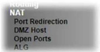
text_image
Routing NAT Port Redirection DMZ Host Open Ports ALGII-4-1 Port Redirection
Port Redirection is usually set up for server related service inside the local network (LAN), such as web servers, FTP servers, E-mail servers etc. Most of the case, you need a public IP address for each server and this public IP address/ domain name are recognized by all users. Since the server is actually located inside the LAN, the network well protected by NAT of the router, and identified by its private IP address/ port, the goal of Port Redirection function is to forward all access request with public IP address from external users to the mapping private IP address/ port of the server.
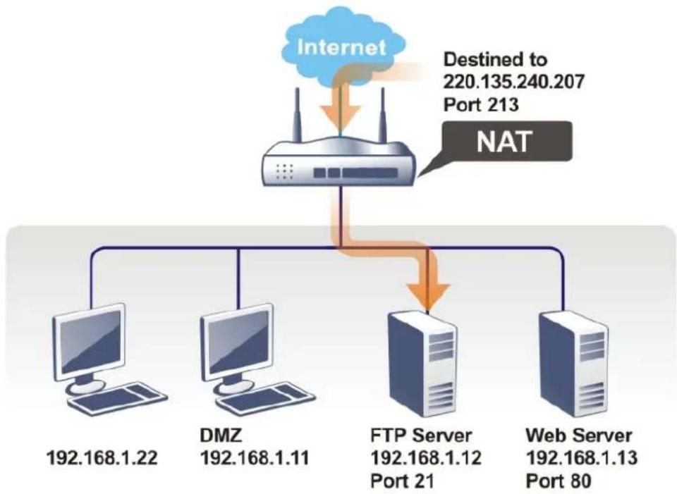
flowchart
graph TD
    A["Internet"] --> B["NAT"]
    B --> C["DMZ 192.168.1.22"]
    B --> D["DMZ 192.168.1.11"]
    B --> E["FTP Server 192.168.1.12 Port 21"]
    B --> F["Web Server 192.168.1.13 Port 80"]
    G["Destined to 220.135.240.207 Port 213"] --> B
The port redirection can only apply to incoming traffic.
To use this function, please go to NAT page and choose Port Redirection web page. The Port Redirection Table provides 40 port-mapping entries for the internal hosts.
Port Redirection
Set to Factory Default
| Index | Enable | Service Name | WAN Interface | Protocol | Public Port | Source IP | Private IP |
| 1. | □ | All | Any | ||||
| 2. | □ | All | Any | ||||
| 3. | □ | All | Any | ||||
| 4. | □ | All | Any | ||||
| 5. | □ | All | Any | ||||
| 6. | □ | All | Any | ||||
| 7. | □ | All | Any | ||||
| 8. | □ | All | Any | ||||
| 9. | □ | All | Any | ||||
| 10. | □ | All | Any |
Note:
The port number values set in this page might be invalid due to the same values configured for Management Port Setup in System Maintenance>>Management, Open VPN and SSL VPN.
Each item is explained as follows:
| Item | Description |
| Index Display the number of the profile. | |
| Enable Check the box to enable the profile. | |
| Service Name Display the description of the specific network service. | |
| WAN Interface Display the WAN IP address used by the profile. | |
| Protocol Display the transport layer protocol (TCP or UDP). | |
| Public Port | Display the port number which will be redirected to the specified Private IP and Port of the internal host. |
| Source IP Display the source IP address or object. | |
| Private IP Display the IP address of the internal host providing the service. | |
Press any number under Index to access into next page for configuring port redirection.
Index No. 1
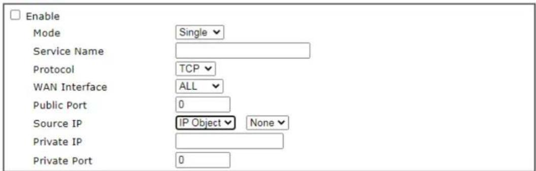
text_image
Enable Mode Single Service Name Protocol TCP WAN Interface ALL Public Port 0 Source IP IP Object None Private IP Private Port 0Note:
In "Range" Mode the End IP will be calculated automatically once the Public Port and Start IP have been entered.

Available settings are explained as follows:
| Item | Description |
| Enable | Check this box to enable such port redirection setting. |
| Mode Two options (Single and Range) are provided here for you to choose. To set a range for the specific service, select Range. In Range mode, if the public port (start port and end port) and the starting IP of private IP had been entered, the system will calculate and display the ending IP of private IP automatically. | |
| Service Name Enter the description of the specific network service. | |
| Protocol Select the transport layer protocol (TCP or UDP). | |
| WAN Interface Select the WAN IP used for port redirection. There are eight WAN IP alias that can be selected and used for port redirection.The default setting is All which means all the incoming data from any port will be redirected to all interfaces. | |
| Public Port | Specify which port can be redirected to the specified Private IP and Port of the internal host. If you choose Range as the port redirection mode, you will see two boxes on this field. Enter the required number on the first box (as the starting port) and the second box (as the ending port). |
| Source IP Use the drop down list to specify an IP object. Or click IP Object link to create a new one for applying. | |
| Private IP Specify the private IP address of the internal host providing the service. If you choose Range as the port redirection mode, you will see two boxes on this field. Type a complete IP address in the first box (as the starting point). The second one will be assigned automatically later. | |
| Private Port Specify the private port number of the service offered by the internal host. | |
After finishing all the settings here, please click OK to save the configuration.
Note that the router has its own built-in services (servers) such as Telnet, HTTP and FTP etc. Since the common port numbers of these services (servers) are all the same, you may need to reset the router in order to avoid confliction.
For example, the built-in web user interface in the router is with default port 80, which may conflict with the web server in the local network, http://192.168.1.13:80. Therefore, you need to change the router's http port to any one other than the default port 80 to avoid conflict, such as 8080. This can be set in the System Maintenance >>Management Setup. You then will access the admin screen of by suffixing the IP address with 8080, e.g., http://192.168.1.1:8080 instead of port 80.
System Maintenance >> Management

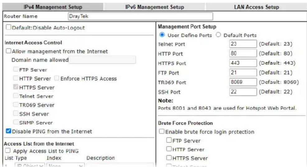
text_image
IPv4 Management Setup IPv6 Management Setup LAN Access Setup Router Name DrayTek □Default:Disable Auto-Logout Internet Access Control □Allow management from the Internet Domain name allowed □FTP Server □HTTP Server □Enforce HTTPS Access □HTTPS Server □Telnet Server □TR069 Server □SSH Server □SNMP Server ✓Disable PING from the Internet Access List from the Internet □Apply Access List to PING List Type Index Description 1 IP Object None Management Port Setup ●User Define Ports ○ Default Ports Telnet Port 23 (Default: 23) HTTP Port 80 (Default: 80) HTTPS Port 443 (Default: 443) FTP Port 21 (Default: 21) TR069 Port 8069 (Default: 8069) SSH Port 22 (Default: 22) Note: Ports 8001 and 8043 are used for Hotspot Web Portal. Brute Force Protection □Enable brute force login protection □FTP Server □HTTP Server □HTTPS Server □Telnet ServerII-4-2 DMZ Host
As mentioned above, Port Redirection can redirect incoming TCP/ UDP or other traffic on particular ports to the specific private IP address/ port of host in the LAN. However, other IP protocols, for example Protocols 50 (ESP) and 51 (AH), do not travel on a fixed port. Vigor router provides a facility DMZ Host that maps ALL unsolicited data on any protocol to a single host in the LAN. Regular web surfing and other such Internet activities from other clients will continue to work without inappropriate interruption. DMZ Host allows a defined internal user to be totally exposed to the Internet, which usually helps some special applications such as Netmeeting or Internet Games etc.
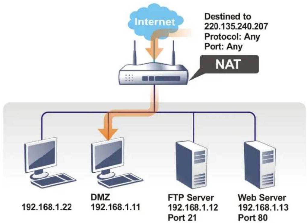
flowchart
graph TD
    A["Internet"] --> B["NAT"]
    B --> C["DMZ 192.168.1.22"]
    B --> D["DMZ 192.168.1.11"]
    B --> E["FTP Server 192.168.1.12 Port 21"]
    B --> F["Web Server 192.168.1.13 Port 80"]
    G["Destined to 220.135.240.207\nProtocol: Any\nPort: Any"] --> A
The security properties of NAT are somewhat bypassed if you set up DMZ host. We suggest you to add additional filter rules or a secondary firewall.
Click DMZ Host to open the following page. You can set different DMZ host for each WAN interface. Click the WAN tab to switch into the configuration page for that WAN.
NAT >> DMZ Host Setup
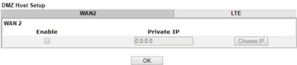
text_image
DMZ Host Setup WAN2 LTE WAN 2 Enable Private IP 0.0.0.0 Choose IP OKAvailable settings are explained as follows:
| Item | Description |
| Enable Check the box to enable the DMZ function. | |
| Private IP Enter the private IP address of the DMZ host, or click Choose IP to select one. | |
| Choose IP | Click this button and then a window will automatically pop up, as depicted below. The window consists of a list of private IP addresses of all hosts in your LAN network. Select one private IP address in the list to be the DMZ host.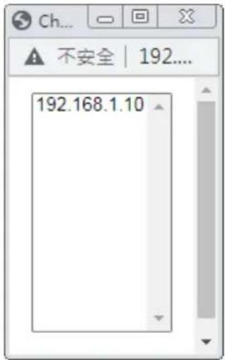 When you have selected one private IP from the above dialog, the IP address will be shown on the screen. Click OK to save the setting. When you have selected one private IP from the above dialog, the IP address will be shown on the screen. Click OK to save the setting. |
If you previously have set up WAN Alias for PPPoE or Static or Dynamic IP mode in WAN interface, you will find them in Aux. WAN IP for your selection.
NAT >> DMZ Host Setup
DMZ Host Setup
| WAN 2 | ||||
| Index | Enable | Aux. WAN IP | Private IP | |
| 1. | ☐ | --- | 0.0.0.0 | Choose IP |
| 2. | ☐ | 192.168.1.89 | 0.0.0.0 | Choose IP |

Available settings are explained as follows:
| Item | Description |
| Enable Check to enable the | DMZ Host function. |
| Private IP Enter the private | IP address of the DMZ host, or click Choose IP to select one. |
| Choose IP | Click this button and then a window will automatically pop up, as depicted below. The window consists of a list of private IP addresses of all hosts in your LAN network. Select one private IP address in the list to be the DMZ host. |
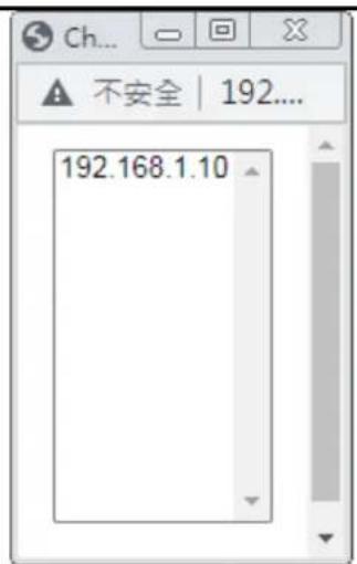
text_image
Ch... ▲ 不安全 | 192.... 192.168.1.10When you have selected one private IP from the above dialog, the IP address will be shown on the screen. Click OK to save the setting.
After finishing all the settings here, please click OK to save the configuration.
II-4-3 Open Ports
Open Ports allows you to open a range of ports for the traffic of special applications.
Common application of Open Ports includes P2P application (e.g., BT, KaZaA, Gnutella, WinMX, eMule and others), Internet Camera etc. Ensure that you keep the application involved up-to-date to avoid falling victim to any security exploits.
Click Open Ports to open the following page:
NAT >> Open Ports
| Index | Enable | Comment | Source IP | Local IP Address |
| 1. | □ | Any | ||
| 2. | □ | Any | ||
| 3. | □ | Any | ||
| 4. | □ | Any | ||
| 5. | □ | Any | ||
| 6. | □ | Any | ||
| 7. | □ | Any | ||
| 8. | □ | Any | ||
| 9. | □ | Any | ||
| 10. | □ | Any |
Note:
The port number values set in this page might be invalid due to the same values configured for Management Port Setup in System Maintenance>>Management, Open VPN and SSL VPN.
Available settings are explained as follows:
| Item | Description |
| Index | Indicate the relative number for the particular entry that you want to offer service in a local host. You should click the appropriate index number to edit or clear the corresponding entry. |
| Enable Check the box to enable the open port profile. | |
| Comment Specify the name | for the defined network service. |
| WAN Interface Display the WAN interface used by such index. | |
| Aux. WAN IP Display the IP | alias setting used by such index. If no IP alias setting exists, such field will not appear. |
| Source IP Display the name | of source IP object. |
| Local IP Address | Display the private IP address of the local host offering the service. |
To add or edit port settings, click one index number on the page. The index entry setup page will pop up. In each index entry, you can specify 10 port ranges for diverse services.
Index No. 1
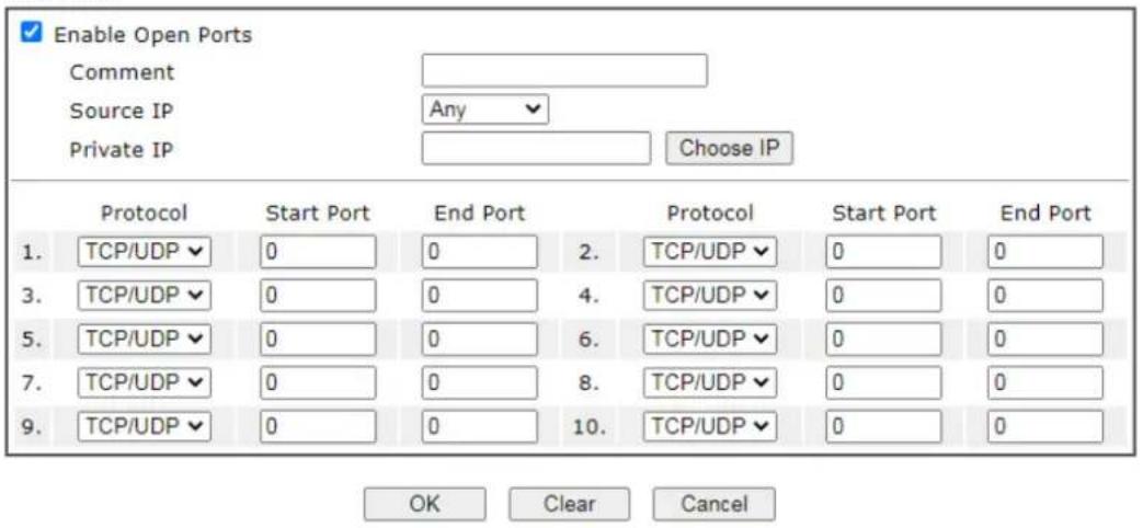
text_image
Enable Open Ports Comment Source IP Any Private IP Choose IP Protocol Start Port End Port Protocol Start Port End Port 1. TCP/UDP 0 0 2. TCP/UDP 0 0 3. TCP/UDP 0 0 4. TCP/UDP 0 0 5. TCP/UDP 0 0 6. TCP/UDP 0 0 7. TCP/UDP 0 0 8. TCP/UDP 0 0 9. TCP/UDP 0 0 10. TCP/UDP 0 0 OK Clear CancelAvailable settings are explained as follows:
| Item | Description |
| Enable Open Ports Check to enable this entry. | |
| Comment Make a name for the defined network application/ service. | |
| Source IP Use the drop down list to specify an IP object. Or click IP Object link to create a new one for applying. | |
| Private IP | Enter the private IP address of the local host or click Choose IP to select one.Choose IP - Click this button and, subsequently, a window having a list of private IP addresses of local hosts will automatically pop up. Select the appropriate IP address of the local host in the list. |
| Protocol | Specify the transport layer protocol. It could be TCP, UDP, or ---- (none) for selection. |
| Start Port Specify the starting port number of the service offered by the local host. | |
| End Port Specify the ending port number of the service offered by the local host. | |
After finishing all the settings here, please click OK to save the configuration.
NAT >> Open Ports
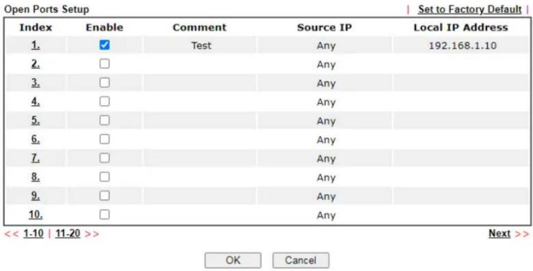
text_image
Open Ports Setup Index Enable Comment Source IP Local IP Address 1. ✓ Test Any 192.168.1.10 2. □ Any 3. □ Any 4. □ Any 5. □ Any 6. □ Any 7. □ Any 8. □ Any 9. □ Any 10. □ Any << 1-10 | 11-20 >> OK Cancel Next >>Note:
The port number values set in this page might be invalid due to the same values configured for Management Port Setup in System Maintenance>>Management, Open VPN and SSL VPN.
II-4-4 ALG
ALG means Application Layer Gateway. There are two methods provided by Vigor router, RTSP (Real Time Streaming Protocol) ALG and SIP (Session Initiation Protocol) ALG, for processing the packets of voice and video.
RTSP ALG makes RTSP message, RTCP message, and RTP packets of voice and video be transmitted and received correctly via NAT by Vigor router.
However, SIP ALG makes SIP message and RTP packets of voice be transmitted and received correctly via NAT by Vigor router.
NAT >> ALG
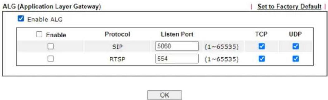
text_image
ALG (Application Layer Gateway) Set to Factory Default Enable ALG Enable Protocol Listen Port TCP UDP SIP 5060 (1~65535) ✓ ✓ RTSP 554 (1~65535) ✓ ✓ OKAvailable settings are explained as follows:
| Item | Description |
| Enable ALG Check to enable such function. | |
| Listen Port Type a port number for SIP or RTSP protocol. | |
| TCP Check the box to make | correspond protocol message packet from TCP transmit and receive via NAT. |
| UDP Check the box to make | correspond protocol message packet from UDP transmit and receive via NAT. |
II-5 Applications
Dynamic DNS
The ISP often provides you with a dynamic IP address when you connect to the Internet via your ISP. It means that the public IP address assigned to your router changes each time you access the Internet. The Dynamic DNS feature lets you assign a domain name to a dynamic WAN IP address. It allows the router to update its online WAN IP address mappings on the specified Dynamic DNS server. Once the router is online, you will be able to use the registered domain name to access the router or internal virtual servers from the Internet. It is particularly helpful if you host a web server, FTP server, or other server behind the router.
Before you use the Dynamic DNS feature, you have to apply for free DDNS service to the DDNS service providers. The router provides up to three accounts from three different DDNS service providers. Basically, Vigor routers are compatible with the DDNS services supplied by most popular DDNS service providers such as www.dyndns.org, www.no-ip.com, www.dtdns.com, www.changeip.com, www.dynamic-nameserver.com. You should visit their websites to register your own domain name for the router.
Schedule
The Vigor router has a built-in clock which can update itself manually or automatically by means of Network Time Protocols (NTP). As a result, you can not only schedule the router to dialup to the Internet at a specified time, but also restrict Internet access to certain hours so that users can connect to the Internet only during certain hours, say, business hours. The schedule is also applicable to other functions.
RADIUS
Remote Authentication Dial-In User Service (RADIUS) is a security authentication client/server protocol that supports authentication, authorization and accounting, which is widely used by Internet service providers. It is the most common method of authenticating and authorizing dial-up and tunneled network users.
The built-in RADIUS client feature enables the router to assist the remote dial-in user or a wireless station and the RADIUS server in performing mutual authentication. It enables centralized remote access authentication for network management.
UPnP
The UPnP (Universal Plug and Play) protocol is supported to bring to network connected devices the ease of installation and configuration which is already available for directly connected PC peripherals with the existing Windows 'Plug and Play' system. For NAT routers, the major feature of UPnP on the router is "NAT Traversal". This enables applications inside the firewall to automatically open the ports that they need to pass through a router.
Web User Interface
Applications
Dynamic DNS
Schedule
RADIUS
UPnP
IGMP
SMS Alert Service
II-5-1 Dynamic DNS
Enable the Function and Add a Dynamic DNS Account
- Assume you have a registered domain name from the DDNS provider, say hostname.dyndns.org, and an account with username: test and password: test.
- Open Applications>>Dynamic DNS.
- In the DDNS setup menu, check Enable Dynamic DNS Setup.
Applications >> Dynamic DNS Setup
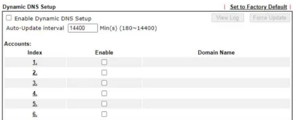
text_image
Dynamic DNS Setup Enable Dynamic DNS Setup Auto-Update interval 14400 Min(s) (180~14400) View Log Force Update Accounts: Index Enable Domain Name 1. □ 2. □ 3. □ 4. □ 5. □ 6. □
Available settings are explained as follows:
| Item | Description |
| Enable Dynamic DNS Setup | Check this box to enable DDNS function. |
| Set to Factory Default | Clear all profiles and recover to factory settings. |
| View Log Display DDNS log status. | |
| Force Update | Force the router updates its information to DDNS server. |
| Auto-Update interval | Set the time for the router to perform auto update for DDNS service. |
| Index Click the number below Index to access into the setting page of DDNS setup to set account(s). | |
| Enable Check the box | to enable this account. |
| Domain Name Display | the domain name that you set on the setting page of DDNS setup. |
- Select Index number 1 to add an account for the router. Check Enable Dynamic DNS Account, and choose correct Service Provider: dyndns.org, Enter the registered hostname: hostname and domain name suffix: dyndns.org in the Domain Name block. The following two blocks should be typed your account Login Name: test and Password: test.
Applications >> Dynamic DNS Setup >> Dynamic DNS Account Setup
Index : 1
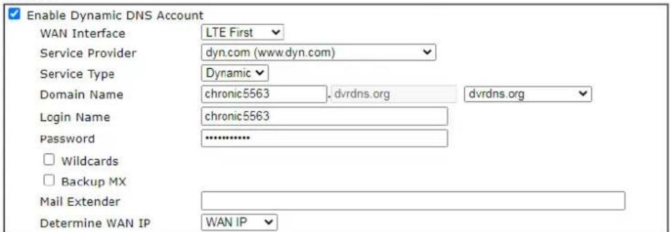
text_image
Enable Dynamic DNS Account WAN Interface LTE First Service Provider dyn.com (www.dyn.com) Service Type Dynamic Domain Name chronic5563 dvrdns.org dvrdns.org Login Name chronic5563 Password ...... □ Wildcards □ Backup MX Mail Extender Determine WAN IP WAN IP
If User-Defined is specified as the service provider, the web page will be changed slightly as follows:
Applications >> Dynamic DNS Setup >> Dynamic DNS Account Setup
Index : 1
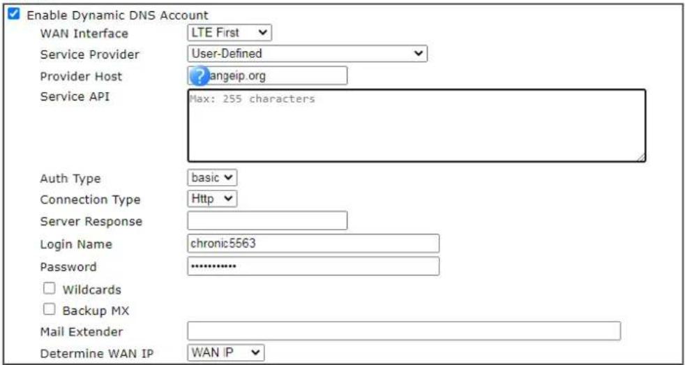
text_image
Enable Dynamic DNS Account WAN Interface LTE First Service Provider User-Defined Provider Host angeip.org Service API Max: 255 characters Auth Type basic Connection Type Http Server Response Login Name chronic5563 Password ............. □ Wildcards □ Backup MX Mail Extender Determine WAN IP WAN IP
Available settings are explained as follows:
| Item | Description |
| Enable Dynamic DNS Account | Check this box to enable the current account. If you did check the box, you will see a check mark appeared on the Active column of the previous web page in step 2). |
| Service Provider Select | ct the service provider for the DDNS account. |
| Provider Host Enter the IP address or the domain name of the host which provides related service. Note that such option is available when Customized is selected as Service Provider. | |
| Service API Enter the | API information obtained from DDNS server. Note that such option is available when Customized is selected as Service Provider. (e.g: / dynamic/ dns/ update.asp?u=jo***&p=jo*********&hostname=j* ***changeip.org&ip=###IP### &cmd=update&offline=0) |
| Auth Type Two types | can be used for authentication. Basic - Username and password defined later can be shown from the packets captured. URL - Username and password defined later can be shown in URL. (e.g., http:// ns1.vigordns.com/ ddns.php?username=xxxx& password=xxxx&domain=xxxx.vigordns.com) Note that such option is available when Customized is selected as Service Provider. |
| Connection Type There are two connection types (HTTP and HTTPS) to be specified. Note that such option is available when Customized is selected as Service Provider. | |
| Server Response Type | any text that you want to receive from the DDNS server. Note that such option is available when Customized is selected as Service Provider. |
| Login Name Enter the | login name that you set for applying domain. |
| Password Enter the p | password that you set for applying domain. |
| Wildcard | The Wildcard feature is not supported for all Dynamic DNS providers. You could get more detailed information from their websites. |
| Mail Extender If the m | mail server is defined with another name, please Enter the name in this area. Such mail server will be used as backup mail exchange. |
| Determine WAN IP | If a Vigor router is installed behind any NAT router, you can enable such function to locate the real WAN IP. When the WAN IP used by Vigor router is private IP, this function can detect the public IP used by the NAT router and use the detected IP address for DDNS update. There are two methods offered for you to choose:WAN IP - If it is selected and the WAN IP of Vigor router is private, DDNS update will take place right away.Internet IP - If it is selected and the WAN IP of Vigor router is private, it will be converted to public IP before DDNS update takes place. |
- Click OK button to activate the settings. You will see your setting has been saved.
Disable the Function and Clear all Dynamic DNS Accounts
Uncheck Enable Dynamic DNS Setup, and click Clear All button to disable the function and clear all accounts from the router.
II-5-2 Schedule
The Vigor router has a built-in clock which can update itself manually or automatically by means of Network Time Protocols (NTP). As a result, you can not only schedule the router to dialup to the Internet at a specified time, but also restrict Internet access to certain hours so that users can connect to the Internet only during certain hours, say, business hours. The schedule is also applicable to other functions.
You have to set your time before set schedule. In System Maintenance>> Time and Date menu, press Inquire Time button to set the Vigor router's clock to current time of your PC. The clock will reset once if you power down or reset the router. There is another way to set up time. You can inquiry an NTP server (a time server) on the Internet to synchronize the router's clock. This method can only be applied when the WAN connection has been built up.
Applications >> Schedule
| Schedule: | Set to Factory Default | ||||
| Index | Enable | Comment | Index | Enable | Comment |
| 1. | 9. | ||||
| 2. | 10. | ||||
| 3. | 11. | ||||
| 4. | 12. | ||||
| 5. | 13. | ||||
| 6. | 14. | ||||
| 7. | 15. | ||||
| 8. | |||||

Available settings are explained as follows:
| Item | Description |
| Set to Factory Default Clear | all profiles and recover to factory settings. |
| Index Click the index number | link to access into the setting page of schedule. |
| Enable Click the box to enable such schedule profile. | |
| Comment Display the name | of the time schedule. |
You can set up to 15 schedules. Then you can apply them to your Internet Access or VPN and Remote Access >> LAN to LAN settings.
To add a schedule:
- Click any index, say Index No. 1.
- The detailed settings of the schedule with index 1 will be shown below.
Index No. 1
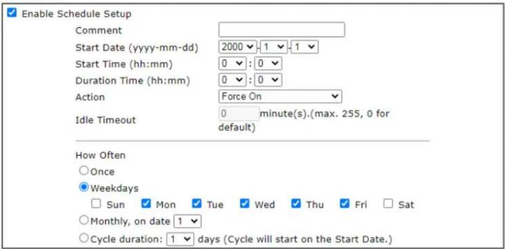
text_image
Enable Schedule Setup Comment Start Date (yyyy-mm-dd) 2000 -1 -1 Start Time (hh:mm) 0 : 0 Duration Time (hh:mm) 0 : 0 Action Force On Idle Timeout 0 minute(s).(max. 255, 0 for default) How Often Once Weekdays Sun Mon Tue Wed Thu Fri Sat Monthly, on date 1 Cycle duration: 1 days (Cycle will start on the Start Date.)Note:
Comment can only contain A-Z a-z 0-9, . { } - _ ( ) ^ \$ ! \~ ` |

Available settings are explained as follows:
| Item | Description |
| Enable Schedule Setup | Check to enable the schedule. |
| Comment Type a short | description for such schedule. |
| Start Date (yyyy-mm-dd) | Specify the starting date of the schedule. |
| Start Time (hh:mm) | Specify the starting time of the schedule. |
| Duration Time (hh:mm) | Specify the duration (or period) for the schedule. |
| Action | Specify which action Call Schedule should apply during the period of the schedule.Force On -Force the connection to be always on.Force Down -Force the connection to be always down.Enable Dial-On-Demand -Specify the connection to be dial-on-demand and the value of idle timeout should be specified in Idle Timeout field.Disable Dial-On-Demand -Specify the connection to be up when it has traffic on the line. Once there is no traffic over idle timeout, the connection will be down and never up again during the schedule. |
| Idle Timeout | Specify the duration (or period) for the schedule. |
| How Often Specify how | often the schedule will be applied.Once -The schedule will be applied just onceWeekdays -Specify which days in one week should perform the schedule.Monthly, on date - The router will only execute the action applied such schedule on the date (1 to 28) of a month.● Cycle duration - Type a number as cycle duration. Then, any action applied such schedule will be executed per several days. For example, “3” is selected as cycle duration. That means, the action applied such schedule will be executed every three days since the date defined on the Start Date. |
3. Click OK button to save the settings.
Example
Suppose you want to control the PPPoE Internet access connection to be always on (Force On) from 9:00 to 18:00 for whole week. Other time the Internet access connection should be disconnected (Force Down).
Office
Hour:
(Force On)


Mon - Sun 9:00 am to 6:00 pm
- Make sure the PPPoE connection and Time Setup is working properly.
- Configure the PPPoE always on from 9:00 to 18:00 for whole week.
- Configure the Force Down from 18:00 to next day 9:00 for whole week.
- Assign these two profiles to the PPPoE Internet access profile. Now, the PPPoE Internet connection will follow the schedule order to perform Force On or Force Down action according to the time plan that has been pre-defined in the schedule profiles.
II-5-3 RADIUS
Remote Authentication Dial-In User Service (RADIUS) is a security authentication client/server protocol that supports authentication, authorization and accounting, which is widely used by Internet service providers. It is the most common method of authenticating and authorizing dial-up and tunneled network users.
The built-in RADIUS client feature enables the router to assist the remote dial-in user or a wireless station and the RADIUS server in performing mutual authentication. It enables centralized remote access authentication for network management.
Vigor router can be operated as a RADIUS client. Therefore, this page is used to configure settings for external RADIUS server. Then LAN user of Vigor router will be authenticated by such server for network application.
Applications >> RADIUS
RADIUS Setup
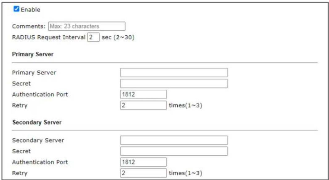
text_image
Enable Comments: Max: 23 characters RADIUS Request Interval 2 sec (2~30) Primary Server Primary Server Secret Authentication Port 1812 Retry 2 times(1~3) Secondary Server Secondary Server Secret Authentication Port 1812 Retry 2 times(1~3)
RADIUS Server Status Log
| Refresh | Clear | |
| _ |
Available settings are explained as follows:
| Item | Description |
| Enable Check to enable RADIUS client feature. | RADIUS Accounting is a network customer billing mechanism for RADIUS server.If enabled, Vigor router will deliver accounting request (e.g., IP address, traffic from the client) to the specified RADIUS server periodically.Comments - Enter a brief description for this profile.RADIUS Request Interval - Set a timeout value for the routerwaiting for a response from the RADIUS server. If no response, Vigor router will send the authentication request again. |
| Primary Server Primary Server | - Enter the IP address of the RADIUS server.Secret - The RADIUS server and client share a secret that is used to authenticate the messages sent between them. Both sides must be configured to use the same shared secret. The maximum length of the shared secret you can set is 36 characters.Authentication Port - The UDP port number that the RADIUS server is using. The default value is 1812, based on RFC 2138.Retry - Set the number of attempts to perform reconnection with RADIUS server. If the connection (with the Primary Server) still fails, stop the connection attempt and begin to make connection with the secondary server. |
| Secondary Server Secondary Server | - Enter the IP address of RADIUS server.Secret - The RADIUS server and client share a secret that is used to authenticate the messages sent between them. Both sides must be configured to use the same shared secret. The maximum length of the shared secret you can set is 36 characters.Authentication Port - The UDP port number that the RADIUS server is using. The default value is 1812, based on RFC 2138.Retry - Set the number of attempts to perform reconnection. If the connection (with the Secondary Server) still fails, stop the connection attempt. The client authentication would be determined as "failed". |
After finished the above settings, click OK button to save the settings.
II-5-4 UPnP
The UPnP (Universal Plug and Play) protocol is supported to bring to network connected devices the ease of installation and configuration which is already available for directly connected PC peripherals with the existing Windows 'Plug and Play' system. For NAT routers, the major feature of UPnP on the router is "NAT Traversal". This enables applications inside the firewall to automatically open the ports that they need to pass through a router.

Info
UPnP is required for some applications such as PPS, Skype, eMule...and etc. If you are not familiar with UPnP, it is suggested to turn off this function for security.
Applications >> UPnP
UPnP
□ Enable UPnP Service
Default WAN ▼
Enable Connection Control Service
Enable Connection Status Service
Note:
To allow NAT pass-through to a UPnP enabled client the connection control service must also be enabled.
OK
Clear
Cancel
Available settings are explained as follows:
| Item | Description |
| Enable UPNP Service | Accordingly, you can enable either the Connection Control Service or Connection Status Service. |
The reminder as regards concern about Firewall and UPnP:
Can't work with Firewall Software
Enabling firewall applications on your PC may cause the UPnP function not working properly. This is because these applications will block the accessing ability of some network ports.
Security Considerations
Activating the UPnP function on your network may incur some security threats. You should consider carefully these risks before activating the UPnP function.
● Some Microsoft operating systems have found out the UPnP weaknesses and hence you need to ensure that you have applied the latest service packs and patches.
● Non-privileged users can control some router functions, including removing and adding port mappings.
The UPnP function dynamically adds port mappings on behalf of some UPnP-aware applications. When the applications terminate abnormally, these mappings may not be removed.
II-5-5 IGMP
IGMP is the abbreviation of Internet Group Management Protocol. It is a communication protocol which is mainly used for managing the membership of Internet Protocol multicast groups.
II-5-5-1 General Setting
Applications >> IGMP
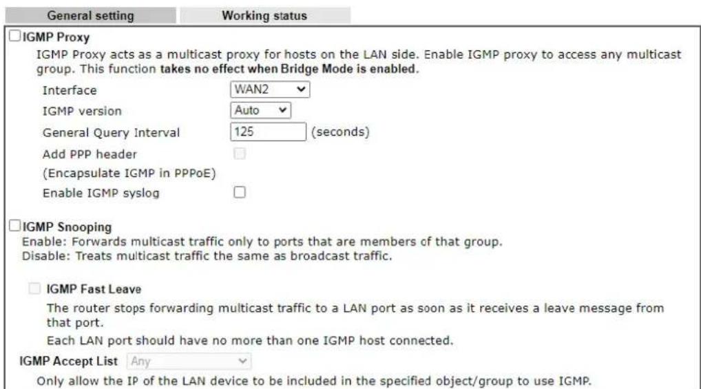
text_image
General setting Working status IGMP Proxy IGMP Proxy acts as a multicast proxy for hosts on the LAN side. Enable IGMP proxy to access any multicast group. This function takes no effect when Bridge Mode is enabled. Interface WAN2 IGMP version Auto General Query Interval 125 (seconds) Add PPP header (Encapsulate IGMP in PPPoE) Enable IGMP syslog IGMP Snooping Enable: Forwards multicast traffic only to ports that are members of that group. Disable: Treats multicast traffic the same as broadcast traffic. IGMP Fast Leave The router stops forwarding multicast traffic to a LAN port as soon as it receives a leave message from that port. Each LAN port should have no more than one IGMP host connected. IGMP Accept List Any Only allow the IP of the LAN device to be included in the specified object/group to use IGMP.
Available settings are explained as follows:
| Item | Description |
| IGMP Proxy Check this box to enable this function. The application of multicast will be executed through WAN / PVC/ VLAN port. In addition, such function is available in NAT mode. Interface - Specify an interface for packets passing through. IGMP version - At present, two versions (v2 and v3) are supported by Vigor router. Choose the correct version based on the IPTV service you subscribe. General Query Interval - Vigor router will periodically check which IP obtaining IPTV service by sending query. It might cause inconvenience for client. Therefore, set a suitable time (unit: second) as the query interval to limit the frequency of query sent by Vigor router. Add PPP header - Check this box if the interface type for IGMP is PPPoE. It depends on the specifications regulated by each ISP. If you have no idea to enable or disable, simply contact your ISP providers. Enable IGMP syslog - Check the box to store the IGMP status onto Syslog. | |
| IGMP Snooping Select to enable IGMP Snooping so that multicast traffic are forwarded to IGMP clients that have joined a multicast group.IGMP Fast Leave - This option is shown only when IGMP Snooping is enabled. Select to enable IGMP Fast Leave. Normally when the router receives a “leave” message from an IGMP host, it will send a last member query message to see if there are still members within the multicast group. When Fast Leave is enabled, multicast for a group is immediately terminated when the last host in that group sends a “leave” message.IGMP Accept List - Only the device with the IP address specified here is able to use IGMP. | |
After finishing all the settings here, please click OK to save the configuration.
II-5-5-2 Working Group
Applications >> IGMP
| General setting | Working status | ||
| Multicast Group Table | |||
| Index | Group ID | P1 | P2 |
IGMP Device Table
| Index | MAC Address | IP Address | Interface | IGMP Version |
Available settings are explained as follows:
| Item | Description |
| Refresh Click this link to renew the working multicast group status. | |
| Group ID | This field displays the ID port for the multicast group. The available range for IGMP starts from 224.0.0.0 to 239.255.255.254. |
| P1 to P2 It indicates the LAN port used for the multicast group. | |
II-5-6 SMS Alert Service
The function of SMS (Short Message Service) Alert is that Vigor router sends a message to user's mobile or e-mail box through specified service provider to assist the user knowing the real-time abnormal situations.
Vigor router allows you to set up to 10 SMS profiles which will be sent out according to different conditions.
This page allows you to specify SMS provider, who will get the SMS, what the content is and when the SMS will be sent.
Applications >> SMS Alert Service
| Index | Enable | SMS Provider | Recipient Number | Notify Profile | Schedule(1-15) | ||
| 1 | 1 - User_SMS | 1 - ??? | None | None | None | ||
| 2 | 1 - User_SMS | 1 - ??? | None | None | None | ||
| 3 | 1 - User_SMS | 1 - ??? | None | None | None | ||
| 4 | 1 - User_SMS | 1 - ??? | None | None | None | ||
| 5 | 1 - User_SMS | 1 - ??? | None | None | None | ||
| 6 | 1 - User_SMS | 1 - ??? | None | None | None | ||
| 7 | 1 - User_SMS | 1 - ??? | None | None | None | ||
| 8 | 1 - User_SMS | 1 - ??? | None | None | None | ||
| 9 | 1 - User_SMS | 1 - ??? | None | None | None | ||
| 10 | 1 - User_SMS | 1 - ??? | None | None | None | ||
Note:
-
All the SMS Alert profiles share the same "Sending Interval" setting if they use the same SMS Provider.
-
If SMS Provider is "LTE Modem", the "Quota" is controlled by LTE >> SMS Quota Limit and the "Sending Interval" is 3 seconds.

Available settings are explained as follows:
| Item | Description |
| Enable Check the box to enable such profile. | |
| SMS Provider | Use the drop down list to choose SMS service provider.You can click SMS Provider link to define the SMS server. |
| Recipient Number Enter the phone number of the one who will receive the SMS. | |
| Notify Profile Use the drop down list to choose a message profile. The recipient will get the content stated in the message profile.You can click the Notify Profile link to define the content of the SMS. | |
| Schedule (1-15) Enter the schedule number that the SMS will be sent out.You can click the Schedule(1-15) link to define the schedule. | |
After finishing all the settings here, please click OK to save the configuration.
Application Notes
A-1 How to use DrayDDNS?
Vigor router supports various DDNS service providers, user can set up user-defined profile to update the DDNS even the service provider is not on the list. Now, DrayTek starts to support our own DDNS service - DrayDDNS. We will provide a domain name for each Vigor Router, this single domain name can record IP addresses of all WAN.
Activate DrayDDNS License
- Go to Wizards >> Service Activation Wizard, wait for the router to connect to MyVigor server, then tick DT-DDNS and I have read and accept the above Agreement, click Next.
Service Activation Wizard
Select the service type that you want to activate
Activation Date : 2019-02-25
Web Content Filter(WCF) Service :
BFJM
License Agreement
This is a web content filter that is provided by the German government. It is a free service without any guarantee and will expire one year after activation. You may re-activate the service after expiry.
Cyren 30-Days Free Trial
License Agreement
This is a worldwide web content filter service. The free trail license can only be used once. At the end of the free trail period you may purchase the official one-year Cyren Web Content Filter from an authorized DrayTek reseller.
Dynamic DNS(DDNS) Service :
DT-DDNS
License Agreement
This is a Dynamic Domain Name Service that is provided by DrayTek company. It is a free service will expire 1 year after activation. You may re-active the service after expiry.
Domain Name: 2017101210301001 .drayddns.com
√ I have read and accept the above Agreement. (Please check this box).
Next > Cancel
- Confirm the information, then click Activate.
Service Activation Wizard
Please confirm your settings
Sevice Type : Trial version
Sevice Activated : Dynamic DNS ( L3W2L1.drayddns.com )
Please click Back to re-select service type you to activate.
< Back Activate Cancel
- MyVigor server will reply with the service activation information.
Service Activation Wizard
Please confirm your settings
DrayTek Service Activation
| Service Name | Start Date | Expire Date | Status |
| Web Content filter | 2019-02-25 | 2019-03-25 | Cyren |
| DDNS | 2019-02-25 | 2019-03-25 | DT-DDNS |
Please check if the license fits with the service provider of your signature. To ensure normal operation for your router, update your signature again is recommended.
Copyright © DrayTek Corp. All Rights Reserved.
< Back
Activate
Cancel
Configure DDNS Profile
- Go to Applications >> Dynamic DNS Setup,
a. Tick Enable Dynamic DNS Setup
b. Click an available profile index
c. Tick Enable Dynamic DNS Account
d. Select DrayTek Global (www.drayddns.com) as Service Provider
e. Select the WAN you would like to upload the IP to DDNS server
f. Click Get domain
g. Click OK on the pop up notification window
Applications >> Dynamic DNS Setup
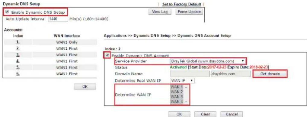
text_image
Dynamic DNS Setup Enable Dynamic DNS Setup Auto-Update Interval 1440 Min(s) (180~14400) Set to Factory Default View Lag Force Update Accounts: Index WAN Interface 1 WAN1 Only 2 WAN1 First 3 WAN1 First 4 WAN1 First 5 WAN1 First 6 WAN1 First OK Applications >> Dynamic DNS Setup >> Dynamic DNS Account Setup Index : 2 Enable Dynamic DNS Account Service Provider DrayTek Global (www.drayddns.com) Status Activated [Start Date:2017-02-23 Expire Date:2018-02-23] Domain Name drayddns.com Get domain Determine Real WAN IP WAN IP Determine WAN IP WAN 1 - WAN 2 WAN 3 WAN 4 - OK Clear Cancel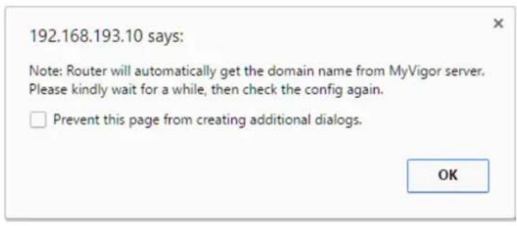
text_image
192.168.193.10 says: Note: Router will automatically get the domain name from MyVigor server. Please kindly wait for a while, then check the config again. □ Prevent this page from creating additional dialogs. OK- Wait few seconds for router to get the domain name, then, we can click the profile to check the information of license and domain name.

text_image
Applications >> Dynamic DNS Setup Dynamic DNS Setup Set to Factory Default Enable Dynamic DNS Setup View Log Force Update Auto-Update interval 1440 Min(s) (180~14400) Accounts: Index WAN Interface Domain Name Active 1 WAN1 Only Customized v 2 WAN 1/2/3/4 ..b:55:581.1e-1 drayddns.com v 3 WAN1 First x 4 WAN1 First 5 WAN1 First 6 WAN1 First Applications >> Dynamic DNS Setup >> Dynamic DNS Account Setup Index : 2 Enable Dynamic DNS Account Service Provider DrayTek Global (www.drayddns.com) Status Activated [Start Date:2017-02-23 Expire Date:2018-02-23] Domain Name 1351735*154 , drayddns.com Edit domain Determine Real WAN IP WAN IP WAN 1 - WAN 2 - WAN 3 - WAN 4 - Determine WAN IP OK Clear CancelModify Domain Name
Currently, only the domain name is allowed to be modified MyVigor website. We will need to register the router to MyVigor server, and log in to MyVigor website to modify it.
- Please visit https://myvigor.draytek.com/ or go to Applications >> Dynamic DNS Setup >> DrayDDNS profile and click Edit domain.
Applications >> Dynamic DNS Setup >> Dynamic DNS Account Setup
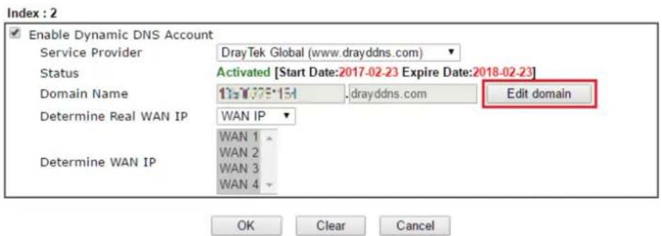
text_image
Index : 2 Enable Dynamic DNS Account Service Provider DrayTek Global (www.drayddns.com) Status Activated [Start Date:2017-02-23 Expire Date:2018-02-23] Domain Name 13:1778*154 .drayddns.com Edit domain Determine Real WAN IP WAN IP WAN 1 WAN 2 WAN 3 WAN 4 Determine WAN IP OK Clear Cancel- Log in to MyVigor Website, choose the profile, then click Edit DDNS settings.
My Information - My Products
Device Information
Device Name: TAT297
Serial Number: 1164550182
Model:Vigor2025 Series
Rename Transfer Back
Device's Service Expired License

text_image
Service WCF BPJM Activate On - - - WCF Cyren Trial On - - - APPE DT-APPE Activate On - - - DDNS DT-DDNS Remove On 2017-02-23 2018-02-23 Edit DDNS settings- Input the desired Domain name (e.g., XXXX25) and click Update.
Edit DDNS Settings
Please note that the DrayDDNS service is currently for internal use only.
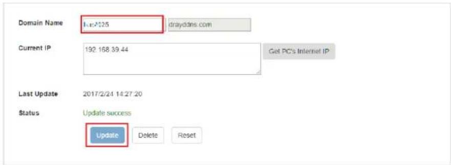
text_image
Domain Name: drayddns.com Current IP: 192.168.39.44 Get PC's Internet IP Last Update: 2017/2/24 14:27:20 Status: Update success Update Delete Reset- Vigor router will get the modified domain name when the it performs next DDNS updating. We can click Sync domain to accelerate this process.
Applications >> Dynamic DNS Setup >> Dynamic DNS Account Setup
Index : 2
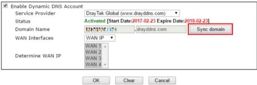
text_image
Enable Dynamic DNS Account Service Provider DrayTek Global (www.drayddns.com) Status Activated [Start Date:2017-02-23 Expire Date:2018-02-23] Domain Name .drayddns.com Sync domain WAN Interfaces WAN IP Determine WAN IP WAN 1 WAN 2 WAN 3 WAN 4 OK Clear CancelAfter few seconds, the router will get the new domain name and print it on the profiles list.
Applications >> Dynamic DNS Setup
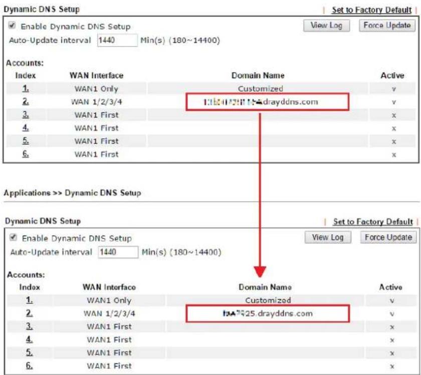
text_image
Dynamic DNS Setup Enable Dynamic DNS Setup Auto-Update interval 1440 Min(s) (180~14400) Set to Factory Default View Log Force Update Accounts: Index WAN Interface Domain Name Active 1. WAN1 Only Customized v 2. WAN 1/2/3/4 trayddns.com v 3. WAN1 First x 4. WAN1 First x 5. WAN1 First x 6. WAN1 First x Applications >> Dynamic DNS Setup Dynamic DNS Setup Set to Factory Default Enable Dynamic DNS Setup View Log Force Update Auto-Update interval 1440 Min(s) (180~14400) Accounts: Index WAN Interface Domain Name Active 1. WAN1 Only Customized v 2. WAN 1/2/3/4 trayddns.com v 3. WAN1 First x 4. WAN1 First x 5. WAN1 First x 6. WAN1 First xA-2 How to Configure Customized DDNS?
This article describes how to configure customized DDNS on Vigor routers to update your IP to the DDNS server. We will take "Changeip.org" and "3322.net" as example. Before setting, please make sure that the WAN connection is up.
Part A: Changeip.org
| Physical Connection | System Uptime: 0day 2:25:59 | ||||
| IPv4 | IPv6 | ||||
| LAN Status | Primary DNS: 168.95.192.1 | Secondary DNS: 168.95.1.1 | |||
| IP Address | TX Packets | RX Packets | |||
| 10.1.7.1 | 2069 | 1036 | |||
| WAN 1 Status | >> Drop PPPoE | ||||
| Enable | Line | Name | Mode | Up Time | |
| Yes | Ethernet | iwiz | PPPoE | 2:25:53 | |
| IP | GW IP | TX Packets | TX Rate(Bps) | RX Packets | RX Rate(Bps) |
| 1.169.185.242 | 168.95.98.254 | 14851 | 9506 | 11281 | 912 |
Note that,
Username: jo***
Password: jo*****
Host name: j****.changeip.org
WAN IP address: 1.169.185.242
Following is the screenshot of editing the HTML script on the browser to update your IP to the DDNS server.
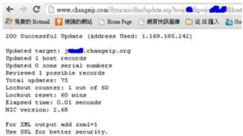
text_image
200 Successful Update (Address Used: 1.169.185.242) Updated target: j...changeip.org Updated 1 host records Updated 0 zone serial numbers Reviewed 1 possible records Total updates: 75 Lockout counter: 1 out of 60 Lockout reset: 60 mins Elapsed time: 0.01 seconds NIC version: 2.68 For XML output add &xml=1 Use SSL for better security.Now we have to configure the router so it can do the same job for us automatically.
- Please go to Applications >> Dynamic DNS to create a profile for user-defined DDNS client.
Applications >> Dynamic DNS Setup >> Dynamic DNS Account Setup
Index : 1
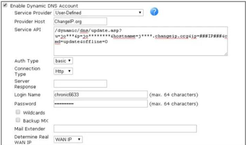
text_image
Enable Dynamic DNS Account Service Provider User-Defined Provider Host ChangelP.org Service API /dynamic/dns/update.asp? u=jo***&p=jo*******&hostname=j****.changeip.org&ip=###IP### md=update&offline=0 Auth Type basic Connection Type Http Server Response Login Name chronic6633 (max. 64 characters) Password ******** (max. 64 characters) Wildcards Backup MX Mail Extender Determine Real WAN IP WAN IP
- Set the Service Provider as User-Defined.
- Set the Service API as:
/ dynamic/ dns/ update.asp?u=j0***&p=j0*******&hostname=j****.changeip.org&ip=###IP
&cmd=update&offline=0
In which, ####IP### is a value which will be replaced with the current interface IP address automatically when DDNS service is running. In this case the IP will be 1.169.185.242.
- After setting, the Customized DDNS service will be up, and our IP will be updated to the DDNS server.
Part B : 3322.net
| WAN 1 | |
| Link Status | : Connected |
| MAC Address | : 00-50-7F-C8-C6-A1 |
| Connection | : PPPoE |
| IP Address | : 111.243.178.53 |
| Default Gateway | : 168.95.98.254 |
| Primary DNS | : 168.95.192.1 |
| Secondary DNS | : 168.95.1.1 |
Username: bi*****
Password: 88*******
Host name: bi*****.3322.org
WAN IP address: 111.243.178.53
To update the IP to the DDNS server via editing the HTML script, we can Enter the following script on the browser:

text_image
members.3322.net/dyndns/update members.3322.net/dyndns/update?hostname=bg3322.org&myip=####P###&wildcard=OFF&mx=mail.exchanger.ext&backmx=NO&offline=NO HTTP/1.1And the result will be :

text_image
members.3322.net/dyndns/update?hostname=b######## 3322.org&myip=#K2JX2JPKX2JX2JX2J&wildcard=OFF&mx=mail.exchanger.ext&backmx=NOSoffline=NOR20HTTP/1.1 members.3322.net /dyndns/update?hostname=b######## 3322.org&myip=#K2JX2JPKX2JX2JX2J&wildcard=OFF&mx=mail.exchanger.ext&backmx=NOSoffline=NOR20HTTP/1.1 good 111.243.178.53"good 111.243.178.53" means our IP has been updated to the server successfully.
Now we have to configure the router so it can do the same job for us automatically.
- Please go to Applications >> Dynamic DNS to create a profile for User-Defined DDNS client.
Applications >> Dynamic DNS Setup >> Dynamic DNS Account Setup
Index : 1
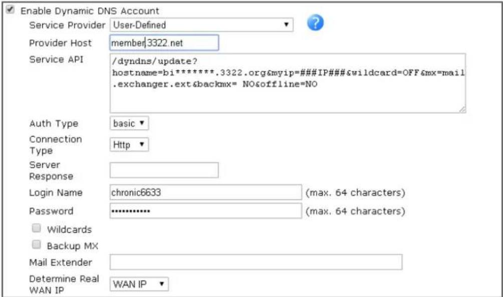
text_image
Enable Dynamic DNS Account Service Provider User-Defined Provider Host member3322.net Service API /dyndns/update? hostname=bi********.3322.org&myip=###IP###&wildcard=OFF&mx=mail .exchanger.ext&backmx= NO&offline=NO Auth Type basic Connection Type Http Server Response Login Name chronic6633 (max. 64 characters) Password ******** (max. 64 characters) Wildcards Backup MX Mail Extender Determine Real WAN IP WAN IP
- Set the Service Provider as User-Defined.
- Set the Provider Host as member.3322.net.
- Set the Service API as: / dyndns/ update?hostname=yourhost.3322.org&myip=###IP###&wildcard=OFF&mx=mail .exchanger.ext&backmx=NO&offline=NO
- Enter your account and password.
- After the setting, the Customized DDNS service will be up, and our IP will be updated to the DDNS server automatically.
Part C : Extend Note
The customized Service Provider is also eligible with the ClouDNS.net.

text_image
ipv4.cloudns.net/api/dynamicURL/?q=MTUzMTE3OJE0NTA1MzA6MDAyODE3MDIiZGQ3ZjNiZmE2M ipv4.cloudns.net api/dynamicURL/?q=MTUzMTE3OJE0NTA1MzA6MDAyODE3MDIiZGQ3ZjNiZmE2M swm.draytek.com/track 2012120610000265 - draytek_swm: DrayTek- DrayTek Vignr2920OK
Applications >> Dynamic DNS Setup >> Dynamic DNS Account Setup
Index : 1
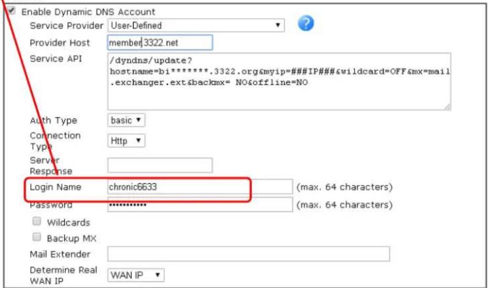
text_image
Enable Dynamic DNS Account Service Provider User-Defined Provider Host member3322.net Service API /dyndns/update? hostname=bi********.3322.org&myip=###IP###&wildcard=OFF&mx=mail .exchanger.ext&backmx= NO&offline=NO Auth Type basic Connection Http Type Server Response Login Name chronic6633 (max. 64 characters) Password ******** (max. 64 characters) Wildcards Backup MX Mail Extender Determine Real WAN IP WAN IP
II-6 Routing
Route Policy (also well known as PBR, policy-based routing) is a feature where you may need to get a strategy for routing. The packets will be directed to the specified interface if they match one of the policies. You can setup route policies in various reasons such as load balance, security, routing decision, and etc.
Through protocol, IP address, port number and interface configuration, Route Policy can be used to configure any routing rules to fit actual request. In general, Route Policy can easily reach the following purposes:
Specify Interface
Through dedicated interface (WAN/ LAN/ VPN), the data can be sent from the source IP to the destination IP.
Address Mapping
Allows you specify the outgoing WAN IP address (es) for an internal private IP address or a range of internal private IP addresses.
Priority
The router will determine which policy will be adopted for transmitting the packet according to the priority of Static Route and Route Policy.
Failover to/Failback
Packets will be sent through another Interface or follow another Policy when the original interface goes down (Failover to). Once the original interface resumes service (Failback), the packets will be returned to it immediately.
Other routing
Specify routing policy to determine the direction of the data transmission.

Info
For more detailed information about using policy route, refer to Support >>FAQ/Application Notes on www.draytek.com.
Web User Interface
Routing
Static Route
Route Policy
BGP
II-6-1 Static Route
Static routing is an alternative to dynamic routing. It is a process that the system network administrator can configure network routers with all the required information for packet forwarding.
Go to Routing >> Static Route. The router offers IPv4 and IPv6 for you to configure the static route. Both protocols bring different web pages.
Static Route for IPv4
Routing >> Static Route Setup
| IPv4 | IPv6 | Set to Factory Default | View Routing Table | ||
| Index | Enable | Destination Address | Index | Enable | Destination Address |
| 1. | □ | ??? | 6. | □ | ??? |
| 2. | □ | ??? | 7. | □ | ??? |
| 3. | □ | ??? | 8. | □ | ??? |
| 4. | □ | ??? | 9. | □ | ??? |
| 5. | □ | ??? | 10. | □ | ??? |

Available settings are explained as follows:
| Item | Description |
| Set to Factory Default Clear | all of the settings and return to factory default settings. |
| Viewing Routing Table Displays the routing table for your reference. | |
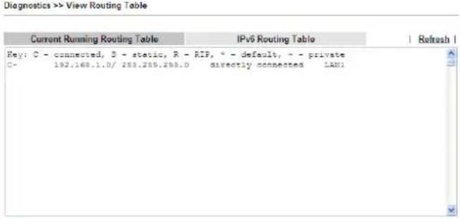 | |
| Index | The number (1 to 30) under Index allows you to open next page to set up static route. |
| Enable Check the box to enable such route. | |
Add Static Routes to Private and Public Networks
Here is an example (based on IPv4) of setting Static Route in Main Router so that user A and B locating in different subnet can talk to each other via the router. Assuming the Internet access has been configured and the router works properly:
- use the Main Router to surf the Internet.
● create a private subnet 192.168.10.0 using an internal Router A (192.168.1.2)
● create a public subnet 211.100.88.0 via an internal Router B (192.168.1.3).
● have set Main Router 192.168.1.1 as the default gateway for the Router A 192.168.1.2.
Before setting Static Route, user A cannot talk to user B for Router A can only forward recognized packets to its default gateway Main Router.
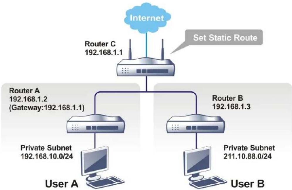
flowchart
graph TD
    A["Internet"] --> B["Router C 192.168.1.1"]
    B --> C["Router A 192.168.1.2 (Gateway:192.168.1.1)"]
    B --> D["Router B 192.168.1.3"]
    C --> E["Private Subnet 192.168.10.0/24"]
    D --> F["Private Subnet 211.10.88.0/24"]
    E --> G["User A"]
    F --> H["User B"]
    I["Set Static Route"] --> B
- Go to LAN page and click General Setup, select 1st Subnet as the RIP Protocol Control. Then click the OK button.

Info
There are two reasons that we have to apply RIP Protocol Control on 1st Subnet. The first is that the LAN interface can exchange RIP packets with the neighboring routers via the 1st subnet (192.168.1.0/24). The second is that those hosts on the internal private subnets (ex. 192.168.10.0/24) can access the Internet via the router, and continuously exchange of IP routing information with different subnets.
- Click the LAN >> Static Route and click on the Index Number 1. Check the Enable box. Please add a static route as shown below, which regulates all packets destined to 192.168.10.0 will be forwarded to 192.168.1.2. Click OK.
Routing >> Static Route Setup
Index No. 1

text_image
Enable Destination IP Address ??? Subnet Mask 255.255.255.255 / 32 Gateway IP Address Network Interface LAN1Note:
WAN5, WAN6, WAN7 are PVCs or VLANs that can be configured on the Multi-PVC/VLAN page.

Available settings are explained as follows:
| Item | Description |
| Enable Click it to enable this profile. | |
| Destination IP Address | Type an IP address as the destination of such static route. |
| Subnet Mask Enter the subnet mask for such static route. | |
| Gateway IP Address Enter the IP address of the gateway. | |
| Network Interface | Use the drop down list to specify an interface for such static route. |
- Return to Static Route Setup page. Click on another Index Number to add another static route as show below, which regulates all packets destined to 211.100.88.0 will be forwarded to 192.168.1.3. Click OK.
Routing >> Static Route Setup
Index No. 1
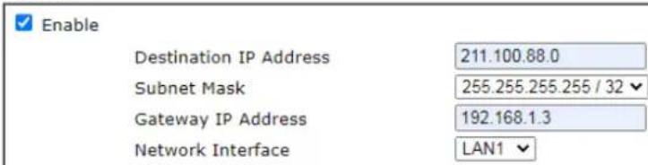
text_image
Enable Destination IP Address 211.100.88.0 Subnet Mask 255.255.255.255 / 32 Gateway IP Address 192.168.1.3 Network Interface LAN1Note:
WAN5, WAN6, WAN7 are PVCs or VLANs that can be configured on the Multi-PVC/VLAN page.

- Go to Diagnostics and choose Routing Table to verify current routing table.
Diagnostics >> View Routing Table
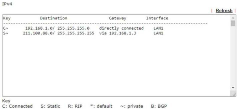
text_image
IPv4 Key Destination Gateway Interface C~ 192.168.1.0/ 255.255.255.0 directly connected LAN1 S~ 211.100.88.0/ 255.255.255.255 via 192.168.1.3 LAN1 Key C: Connected S: Static R: RIP #: default ~: private B: BGPNote: WAN5, WAN6, WAN7 are router-borne WANs.
| Destination | Interface Flags | Metric | Next Hop | |
| FE80::/64 | LAN1 | U | 256 | :: |
| FF00::/8 | LAN1 | U | 256 | :: |
Static Route for IPv6
You can set up to 40 profiles for IPv6 static route. Click the IPv6 tab to open the following page:
Routing >> Static Route Setup
| IPv4 | IPv6 | Set to Factory Default | View IPv6 Routing Table | ||
| Index | Enable | Destination Address | Index | Enable | Destination Address |
| 1. | ☐ | ::/0 | 11. | ☐ | ::/0 |
| 2. | ☐ | ::/0 | 12. | ☐ | ::/0 |
| 3. | ☐ | ::/0 | 13. | ☐ | ::/0 |
| 4. | ☐ | ::/0 | 14. | ☐ | ::/0 |
| 5. | ☐ | ::/0 | 15. | ☐ | ::/0 |
| 6. | ☐ | ::/0 | 16. | ☐ | ::/0 |
| 7. | ☐ | ::/0 | 17. | ☐ | ::/0 |
| 8. | ☐ | ::/0 | 18. | ☐ | ::/0 |
| 9. | ☐ | ::/0 | 19. | ☐ | ::/0 |
| 10. | ☐ | ::/0 | 20. | ☐ | ::/0 |
Available settings are explained as follows:
| Item | Description |
| Set to Factory Default Clear | all of the settings and return to factory default settings. |
| Viewing IPv6 Routing Table | Displays the routing table for your reference. |
| Index | The number (1 to 40) under Index allows you to open next page to set up static route. |
| Enable Check the box to enable such static route. | |
| Destination Address Displays the destination address of the static route. | |
Click any underline of index number to get the following page.
LAN >> Static Route Setup
Index No. 1

text_image
Enable Destination IPv6 Address / Prefix Len : : / 0 Gateway IPv6 Address Network Interface LAN1 ▼
Available settings are explained as follows:
| Item | Description |
| Enable Click it to enable this profile. | |
| Destination IPv6 Address / Prefix Len | Enter the IP address with the prefix length for this entry. |
| Gateway IPv6 Address Enter the gateway address for this entry. | |
| Network Interface | Use the drop down list to specify an interface for this static route. |
When you finish the configuration, please click OK to save and exit this page.
II-5-2 Route Policy
TheRoute Policy feature gives you control over how different types of outbound traffic are routed, through any of the LANs, WANs or VPNs. The policy set in Route Policy always has higher priority than Default Route, and always has lower priority than the Firewall Rules. Administrator may also define a priority to this policy.
To add, delete or modify load balance or route policies, select Routing >> Route Policy from the menu bar.
Routing >> Route Policy

| Route Policy | Set to Factory Default | Diagnose | ||||||||||
| Index | Enable | Protocol | Interface | Priority | Src IP Start | Src IP End | Dest IP Start | Dest IP End | Dest Port Start | Dest Port End | Move Up | Move Down |
| 1 | □ | Any | WAN1 | 200 | Any | Any | Any | Any | Any | Any | Down | |
| 2 | □ | Any | WAN1 | 200 | Any | Any | Any | Any | Any | Any | UP | Down |
| 3 | □ | Any | WAN1 | 200 | Any | Any | Any | Any | Any | Any | UP | Down |
| 4 | □ | Any | WAN1 | 200 | Any | Any | Any | Any | Any | Any | UP | Down |
| 5 | □ | Any | WAN1 | 200 | Any | Any | Any | Any | Any | Any | UP | Down |
| 6 | □ | Any | WAN1 | 200 | Any | Any | Any | Any | Any | Any | UP | Down |
| 7 | □ | Any | WAN1 | 200 | Any | Any | Any | Any | Any | Any | UP | Down |
| 8 | □ | Any | WAN1 | 200 | Any | Any | Any | Any | Any | Any | UP | Down |
| 9 | □ | Any | WAN1 | 200 | Any | Any | Any | Any | Any | Any | UP | Down |
| 10 | □ | Any | WAN1 | 200 | Any | Any | Any | Any | Any | Any | UP | |
○ Wizard Mode: most frequently used settings in three pages
Advance Mode: all settings in one page
OK
Available settings are explained as follows:
| Item | Description |
| Set to Factory Default Clear | the settings of all Load-Balance and Route Policy rules. |
| Index Rule index. Click to bring up the configuration page of the rule. | |
| Enable Select to enable this rule. | |
| Protocol Protocol(s) to which this rule applies. | |
| Interface LAN, IP Routed Subnet, WAN or VPN interface that the traffic described by this rule is to be directed. | |
| Priority The priority of this rule. | |
| Src IP Start The beginning source IP address. | |
| Src IP End The ending source IP address. | |
| Dest IP Start The beginning destination IP address. | |
| Dest IP End The ending destination IP address. | |
| Dest Port Start The beginning destination port number. | |
| Dest Port End The ending destination port number. | |
| Move UP/Move Down Click to shift priority of rule up/ down by one. | |
| Wizard Mode | The setup wizard will present the most-commonly used rule settings in three steps. |
| Advance Mode All the rule settings will be shown on one configuration page. |
If Wizard Mode is selected, you will be guided through the configuration process in three steps. Only the most commonly used settings will be shown.
-
Click the Wizard Mode radio button.
-
Click Index 1. The setting page will appear as follows:
Routing >> Load-Balance/Route Policy
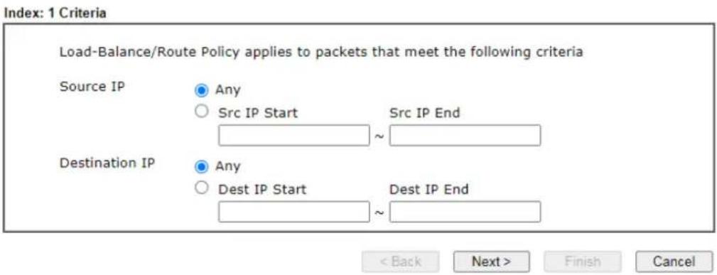
text_image
Index: 1 Criteria Load-Balance/Route Policy applies to packets that meet the following criteria Source IP Any Src IP Start Src IP End Destination IP Any Dest IP Start Dest IP End < Back Next > Finish CancelAvailable settings are explained as follows:
| Item | Description |
| Source IP | Source IP addresses to which this rule is to be applied.Any - This rule applies to all source IP addresses.Src IP Start, Src IP End - This rule applies to the specified range of source IP addresses. If there is only one source IP address, enter the address in both the Start and End fields. |
| Destination IP Destination IP addresses to which this rule is to be applied.Any - This rule applies to all destination IP addresses.Dest IP Start, Dest IP End - This rule applies to the specified range of destination IP addresses. If there is only one destination IP address, enter the address in both the Start and End fields. | |
- Click Next to get the following page.
Routing >> Load-Balance/Route Policy
Index: 1 Interface

text_image
Load-Balance/Route Policy directs the packets to the interface below Interface WAN1
Available settings are explained as follows:
| Item | Description |
| Interface | You can select an interface from one of the following: WAN, LAN, VPN, IP Routed Subnet, and LTE. Packets match with the above criteria will be transferred to the interfacechosen here. Select an interface from the list. |
- Specify an interface and click Next. The following page will appear only if you choose WAN1 \~WAN7 as Interface.
Routing >> Load-Balance/Route Policy
Index: 1 NAT or Routing

text_image
Based on the settings in the previous pages, we guess you want to have: Force NAT The current setting is: ● Force NAT ○ Force Routing
Available settings are explained as follows:
| Item | Description |
| Force NAT /Force Routing | It determines which mechanism that the router will use to forward the packet to WAN. |
- After choosing the mechanism, click Next to get the summary page for reference.
Load-Balance/Route Policy
Index: 1 Configuration Summary
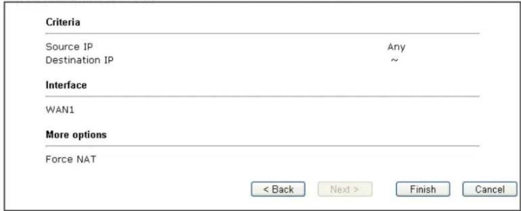
text_image
Criteria Source IP Any Destination IP ~ Interface WAN1 More options Force NAT < Back Next > Finish Cancel- If there is no error, click Finish to complete wizard setting. To make changes, click Back to return to the previous pages. To discard all changes, click Cancel.
If Advance Mode is selected, you will be presented with a single page with all the configurable settings for the rule.
- Click the Advance Mode radio button.
- Click Index 1 to access into the following page.
Routing >> Load-Balance/Route Policy
Index: 1
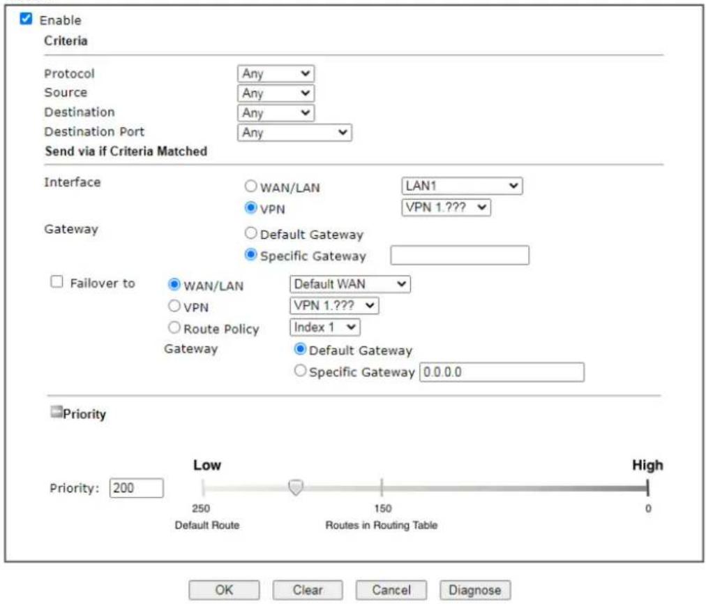
text_image
Enable Criteria Protocol Any Source Any Destination Any Destination Port Any Send via if Criteria Matched Interface WAN/LAN LAN1 VPN VPN 1.??? Gateway Default Gateway Specific Gateway Failover to WAN/LAN Default WAN VPN VPN 1.??? Route Policy Index 1 Gateway Default Gateway Specific Gateway 0.0.0.0 Priority Priority: 200 Low High 250 150 0 Default Route Routes in Routing Table OK Clear Cancel DiagnoseAvailable settings are explained as follows:
| Item | Description |
| Enable Select to enable | rule and unlock all fields for configuration. |
| Criteria | Router examines outgoing LAN traffic to find the first rule whose criteria are satisfied.Protocol - Use the drop-down menu to choose a proper protocol for the WAN interface.Source - Source IP addresses to which this rule is to be applied.Any - This rule applies to all source IP addresses.IP Range -This rule applies to the specified range of source IP addresses.- Start - Enter an address as the starting IP for such profile.- End - Enter an address as the ending IP for such profile.IP Subnet - This rule applies to source IP addresses defined by the specified network IP address and subnet mask.- Network - Enter an IP address here.- Mask - Use the drop down list to choose a suitable mask for the network.● IP Object / IP Group - Use the drop down list to choose a preconfigured IP object/ group.Destination - Destination IP addresses to which this rule is to be applied.● Any - This rule applies to all source IP addresses.● IP Range -This rule applies to the specified range of destination IP addresses.- Start - Enter an address as the starting IP for such profile.- End - Enter an address as the ending IP for such profile.● IP Subnet - This rule applies to destination IP addresses defined by the specified network IP address and subnet mask.- Network - Enter an IP address here.- Mask - Use the drop down list to choose a suitable mask for the network.● Domain Name - Specify a domain name as the destination.- Select - Click it to choose an existing domain name defined in Objects Setting>>String Object.- Delete - Remove current used domain name.- Add - Create a new domain name as the destination.● IP Object / IP Group - Use the drop down list to choose a preconfigured IP object/ group.Destination Port - Destination port numbers to which this rule is to be applied. As only TCP and UDP protocols use port numbers, this setting does not apply to the ICMP protocol.● Any - This rule applies to all destination ports.● Dest Port Range - This rule applies to the specified range of destination ports.- Start - Enter the destination port start for the destination IP.- End - Enter the destination port end for the destination IP. If this field is blank, it means that all the destination ports will be passed through the WAN interface. |
| Send to if criteria matched | If criteria are matched, the traffic will be sent to the designated interface and gateway.Interface - Packets match with the above criteria will be transferred to the interface chosen here. Select an interface from the list (WAN/ LAN: A WAN or LAN interface; VPN: A Virtual Private Network; PVC).Interface Mode - It is available if WAN is selected as the Interface.Gateway - Select a gateway.● Default Gateway - Traffic will be sent to the default gateway address of the specified interface.● Specific Gateway - Traffic will be sent to thespecified gateway address instead of the default gateway address.Failover to - If the interface specified above loses connection, traffic can be forwarded to an alternate interface or be scrutinized by an alternate route policy.WAN/LAN - Use the drop down list to choose an interface as an auto failover interface.VPN - Use the drop down list to choose a VPN tunnel as a failover tunnel.Route Policy - Use the drop down list to choose an existed route policy profile.Gateway - The failed-over traffic can be sent to the Default Gateway of the alternate interface/ route policy, or a Specific Gateway at the specified IP address.Failback- When Failover to option is enabled,Administrator could also enable Failback to clear the existing session on Failover interface and return to the original interface immediately once the original interface resume its service. When Failback is not enabled, the router will only stop sending packets via the Failover interface when the existing sessions are cleared, and this might take a long time because some application will keep sending packet once a while. Therefore, Failback option is recommended if Administrator wants the traffic to go via the primary interface as soon as possible. |
| Priority Specifies the priority of the rule in relation to other rules.Lowering the priority value increases the priority of the rule, and vice versa. Routes in the routing table have a priority value of 150, whereas the default routes have a priority value of 250.The default priority value of Load Balance/ Route Policy rules is 200. To change the priority, move the slider or enter a value. | |
- When you finish the configuration, please click OK to save and exit this page.
Diagnose for Route Policy
The Diagnose function allows you to determine how a specific type of traffic from a host to a destination will be routed, and which routes, route policies and load balance rules match the criteria of the traffic.
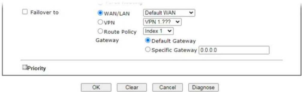
text_image
Failover to WAN/LAN Default WAN VPN VPN 1.??? Route Policy Index 1 Gateway Default Gateway Specific Gateway 0.0.0.0 Priority OK Clear Cancel DiagnoseClick Diagnose.
Analyze a single packet
Select this mode to make Vigor router analyze how a single packet will be sent by a route policy.
Diagnostics >> Route Policy Diagnosis
Test how the packets will be routed

Analyze a single packet
○ Analyze multiple packets by uploading an input file
Packet Information
| Protocol | Any | ✓ |
| Src IP | Specify an IP | 192.168.1.1 |
| Dst IP | Specify an IP | 8.8 8.8 |
| Dst Port | Any Port | ✓ |
Analyze
Available settings are explained as follows:
| Item | Description |
| Packet Information Specify | the nature of the packets to be analyzed by Vigor router.Protocol - Specify a protocol for diagnosis.Src IP - IP address of host where the traffic originates.Specify an IP - One source IP address.Any IP- Source IP address is not specified. Any IP from LAN X/ IP Routed Subnet.Subnet/IP Routed Subnet - Any source IP address on the specified subnet.Dst IP - IP address of the destination host.Specify an IP - One destination IP address.Any IP - Destination IP address is not specified.Dst Port - Number of port to which the traffic is sent. This setting is only applicable to UDP and TCP protocols. Use the drop down list to specify the destination port.Analyze - Click to analyze and display routes, route policies and load balance rules with matching criteria. If required, click export analysis to export the result as a file. |
The following shows an analysis example. The packet matched the criteria of one route policy.
Test how the packets will be routed
Modo ● Analyze a single packet
○ Analyze multiple packets by uploading an input file
Packet Information
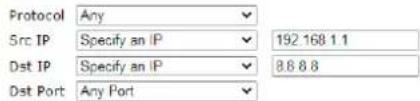
text_image
Protocol Any Src IP Specify an IP 192.168 1.1 Dst IP Specify an IP 8.8 8.8 Dst Port Any PortAnalyze
Analysis
the packet

LAN
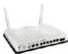
Vigor2865
The packet was dropped because the send-to interface of the matched policy "policy 1" was inactive and there was no fallover setting
Matched Route
| Matched | Priority |
| N/A | N/A |
Matched Policy
| Matched | Priority | failovered |
| Route Policy 1 | 200 | No |
close
Analyze multiple packets by uploading an input file
Diagnostics >> Route Policy Diagnosis

Test how the packets will be routed
Mode ○ Analyze a single packet
Analyze multiple packets by uploading an input file
Input File
選擇檔案 未選擇任何檔案
( download an example input file)
Analyze
Available settings are explained as follows:
| Item | Description |
| Input File Browse - Click to | browse folder structure and select an input file.Download and example input file - Click to download a sample input file (blank “.csv” file). Then, click the Browse button to select that blank “.csv” file for saving the result of analysis. |
| Nodeanalyze how a packet will be sentana下载工作確認 | |
| Input Filediagnose_example_input_file.csv402 BAnalyze儲存至 下載下載後開幕 儲存 取消 | |
| Analyze - After selecting input file, click to start theanalysis process. Click the export button to export the result as a file.Note that the analysis was based on the current "load-balance/ route policy" settings, we do not guarantee it will be 100% the same as the real case. |
The following shows the analysis of the sample input file. The matched routes and policies are highlighted in green. The Final Result column shows the outcome.
Diagnostics >> Route Policy Diagnosis

Test how the packets will be routed
Mode
Analyze a single packet
Analyze multiple packets by uploading an input file
Input Fillo

( download an example input file)
Analyze
Analysis

| Input Packet Information | Matched Route | Matched Policy | Final Result | ||||||||
| Profile | Proto | Src IP | Dst IP | Dst Port | Route | Priority | Policy | Priority | failovered | Interface | Reason |
| LA-branch | ICMP | 192.168.1.10 | 10.10.10.10 | Any | No Match | N/A | No Match | N/A | No | (null) | The packet was dropped because neither "route" or "policy" was matched |
| NY-branch | TCP | 192.168.1.20 | 20.20.20.20 | 5060 | No Match | N/A | No Match | N/A | No | (null) | The packet was dropped because neither "route" or "policy" was matched |
| No Match | The packet was dropped because | ||||||||||
II-5-3 BGP
Border Gateway Protocol (BGP) is a standardized protocol designed to exchange routing and reachability information among autonomous systems (AS) on the Internet.
II-5-3-1 Basic Settings
Set general settings for for local router and neighboring routers.
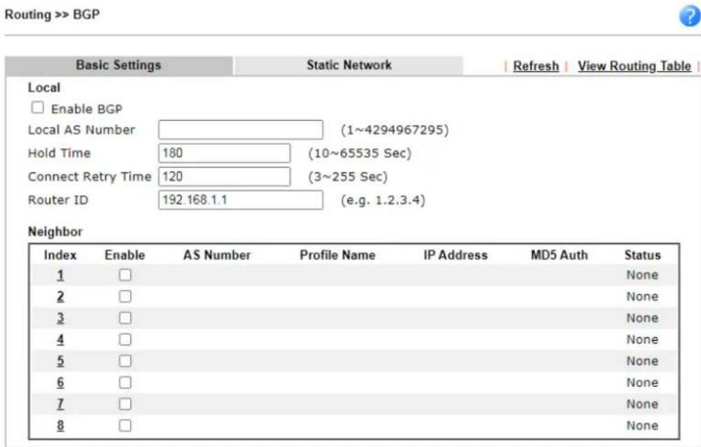
text_image
Routing >> BGP Basic Settings Static Network Refresh View Routing Table Local Enable BGP Local AS Number (1~4294967295) Hold Time 180 (10~65535 Sec) Connect Retry Time 120 (3~255 Sec) Router ID 192.168.1.1 (e.g. 1.2.3.4) Neighbor Index Enable AS Number Profile Name IP Address MD5 Auth Status 1 □ None 2 □ None 3 □ None 4 □ None 5 □ None 6 □ None 7 □ None 8 □ None
Available settings are explained as follows:
| Item | Description |
| Local | |
| Enable BGP Check the box to enable basic BGP function for local router. | |
| Local AS Number Set the AS number for local router. | |
| Hold Time Set the time interval (in seconds) to determine the peer is dead when the router is unable to receive any keepalive message from the peer within the time. | |
| Connect Retry Time | If the router fails to connect to neighboring router, it requires a period of time to reconnect.Set the time interval to do reconnection. |
| Router ID Specify the LAN subnet for the router. | |
| Neighbor | |
| Enable Check the box to enable the basic BGP function for neighboring router. | |
| Index Click the index number link to configure neighbor profile. | |
| AS Number Display the AS N | Number for neighboring router. |
| Profile Name Display the name of the neighboring profile. | |
| IP Address Display the IP address specified for the neighboring profile. | |
| MD5 Auth Display the status (enabled or disabled) of MD5 authentication. | |
| Status | Display the connection status for local router and neighboring router. |
II-5-3-2 Static Network
This page allows you to configure up to eight neighboring routers for exchanging the routing information with the local router.
Routing >> BGP
| Basic Settings | Static Network | | View Routing Table | | |
| Select | Index | IP Address | Subnet Mask |
| □ | 1 | 255.255.255.254 / 31 ▼ | |
| □ | 2 | 255.255.255.254 / 31 ▼ | |
| □ | 3 | 255.255.255.254 / 31 ▼ | |
| □ | 4 | 255.255.255.254 / 31 ▼ | |
| □ | 5 | 255.255.255.254 / 31 ▼ | |
| □ | 6 | 255.255.255.254 / 31 ▼ | |
| □ | 7 | 255.255.255.254 / 31 ▼ | |
| □ | 8 | 255.255.255.254 / 31 ▼ | |
| □ | 9 | 255.255.255.254 / 31 ▼ | |
| □ | 10 | 255.255.255.254 / 31 ▼ | |
| □ | 11 | 255.255.255.254 / 31 ▼ | |
| □ | 12 | 255.255.255.254 / 31 ▼ | |
| □ | 13 | 255.255.255.254 / 31 ▼ | |
| □ | 14 | 255.255.255.254 / 31 ▼ | |
| □ | 15 | 255.255.255.254 / 31 ▼ | |
| □ | 16 | 255.255.255.254 / 31 ▼ | |

Available settings are explained as follows:
| Item | Description |
| Select Check the box to enable the configuration for the selected index entry. | |
| IP Address Enter the IP address for a router. | |
| Subnet Mask Use the drop down list to specify a subnet mask for the IP address. | |
This page is left blank.
Part III Wireless LAN

Wireless
Wireless LAN enables high mobility so WLAN users can simultaneously access all LAN facilities just like on a wired LAN as well as Internet access.
III-1 Wireless LAN
This function is used for "n" model only.
Over recent years, the market for wireless communications has enjoyed tremendous growth. Wireless technology now reaches or is capable of reaching virtually every location on the surface of the earth. Hundreds of millions of people exchange information every day via wireless communication products. The VigorLTE 200 wireless series router (with "n", or "ac" in model name) is designed for maximum flexibility and efficiency of a small office/home. Any authorized staff can bring a built-in WLAN client PDA or notebook into a meeting room for conference without laying a clot of LAN cable or drilling holes everywhere. Wireless LAN enables high mobility so WLAN users can simultaneously access all LAN facilities just like on a wired LAN as well as Internet access.
The Vigor wireless routers are equipped with a wireless LAN interface compliant with the standard IEEE 802.11n draft 2 protocol. To boost its performance further, the Vigor Router is also loaded with advanced wireless technology to lift up data rate up to 300 Mbps*. Hence, you can finally smoothly enjoy stream music and video.
VigorLTE 200 wireless router is a highly integrated wireless local area network (WLAN) for 5 GHz 802.11ac or 2.4/5 GHz 802.11n WLAN applications. It supports channel operations of 20/40 MHz at 2.4 GHz and 20/40/80 MHz at 5 GHz. VigorLTE 200 “ac” series router can support data rates up to 1.3 Gbps in 802.11ac 80 MHz channels. VigorLTE 200 “n” series router supports 802.11n up to 300 Mbps for 40 MHz channel operations.

Info
The actual data throughput will vary according to the network conditions and environmental factors, including volume of network traffic, network overhead and building materials.
In an Infrastructure Mode of wireless network, Vigor wireless router plays a role as an Access Point (AP) connecting to lots of wireless clients or Stations (STA). All the STAs will share the same Internet connection via Vigor wireless router. The General Settings will set up the information of this wireless network, including its SSID as identification, located channel etc.
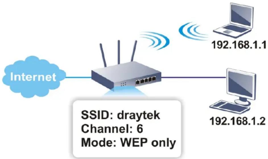
flowchart
graph LR
    A["Internet"] --> B["Router"]
    B --> C["192.168.1.1"]
    B --> D["192.168.1.2"]
    style A fill:#fff,stroke:#333
    style B fill:#ccc,stroke:#333
    style C fill:#fff,stroke:#333
    style D fill:#fff,stroke:#333
    note bottom of B SSID: draytek
        Channel: 6
        Mode: WEP only
Multiple SSIDs
Vigor router supports four SSID settings for wireless connections. Each SSID can be defined with different name and download/upload rate for selecting by stations connected to the router wirelessly.
Real-time Hardware Encryption
Vigor Router is equipped with a hardware AES encryption engine so it can apply the highest protection to your data without influencing user experience.
Complete Security Standard Selection
To ensure the security and privacy of your wireless communication, we provide several prevailing standards on market.
WEP (Wired Equivalent Privacy) is a legacy method to encrypt each frame transmitted via radio using either a 64-bit or 128-bit key. Usually access point will preset a set of four keys and it will communicate with each station using only one out of the four keys.
WPA (Wi-Fi Protected Access), the most dominating security mechanism in industry, is separated into two categories: WPA-personal or called WPA Pre-Share Key (WPA/PSK), and WPA-Enterprise or called WPA/802.1x.
In WPA-Personal, a pre-defined key is used for encryption during data transmission. WPA applies Temporal Key Integrity Protocol (TKIP) for data encryption while WPA2 applies AES. The WPA-Enterprise combines not only encryption but also authentication.
Since WEP has been proved vulnerable, you may consider using WPA for the most secure connection. You should select the appropriate security mechanism according to your needs. No matter which security suite you select, they all will enhance the over-the-air data protection and/or privacy on your wireless network. The Vigor wireless router is very flexible and can support multiple secure connections with both WEP and WPA at the same time.

Info
The password (PSK) of default security mode is provided and stated on the label pasted on the bottom of the router. For the wireless client who wants to access into Internet through such router, please input the default PSK value for connection.
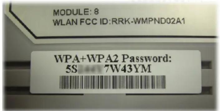
text_image
MODULE: 8 WLAN FCC ID:RRK-WMPND02A1 WPA+WPA2 Password: 5S 7W43YMSeparate the Wireless and the Wired LAN-WLAN Isolation
It enables you to isolate your wireless LAN from wired LAN for either quarantine or limit access reasons. To isolate means neither of the parties can access each other. To elaborate an example for business use, you may set up a wireless LAN for visitors only so they can connect to Internet without hassle of the confidential information leakage. For a more flexible deployment, you may add filters of MAC addresses to isolate users' access from wired LAN.
Manage Wireless Stations - Station List
It will display all the stations in your wireless network and the status of their connection.
WPS
WPS (Wi-Fi Protected Setup) provides easy procedure to make network connection between wireless station and wireless access point (vigor router) with the encryption of WPA and WPA2.
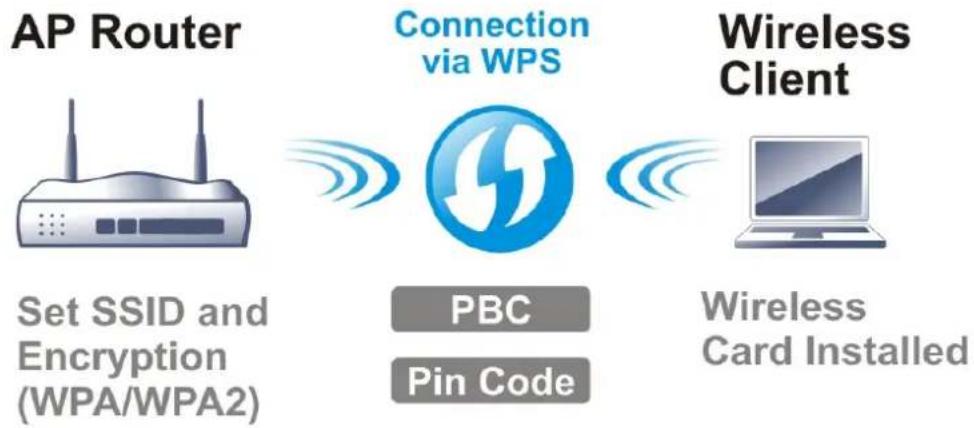
flowchart
graph LR
    A["AP Router"] -->|Set SSID and Encryption (WPA/WPA2)| B["Connection via WPS"]
    B -->|PBC\nPin Code| C["Wireless Client"]
    C -->|Wireless Card Installed| D["Computer"]

Info
WPS is available for the wireless station with WPS supported.
It is the simplest way to build connection between wireless network clients and vigor router. Users do not need to select any encryption mode and type any long encryption passphrase to setup a wireless client every time. He/she only needs to press a button on wireless client, and WPS will connect for client and router automatically.
There are two methods to do network connection through WPS between AP and Stations: pressing the Start PBC button or using PIN Code.
- On the side of VigorLTE 200 series which served as an AP, press WPS button once on the front panel of the router or click Start PBC on web configuration interface. On the side of a station with network card installed, press Start PBC button of network card.
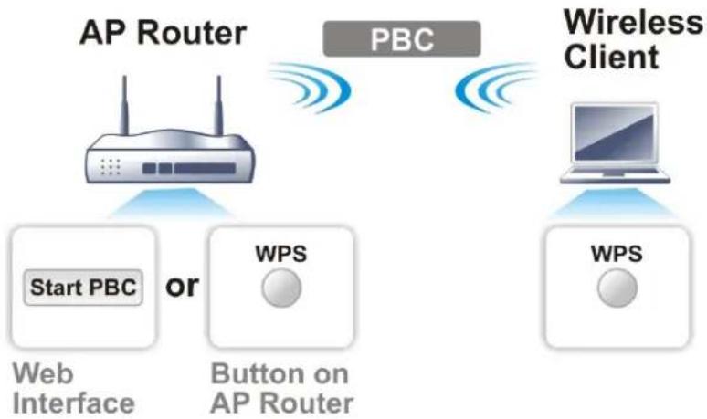
flowchart
graph TD
    A["AP Router"] -->|Start PBC or| B["Web Interface"]
    A -->|Start PBC or| C["Button on AP Router"]
    D["Wireless Client"] -->|WPS| E["WPS"]
    D -->|WPS| F["Computer"]
    style A fill:#f9f,stroke:#333
    style D fill:#ccf,stroke:#333
    style B fill:#cfc,stroke:#333
    style C fill:#fcc,stroke:#333
    style E fill:#cff,stroke:#333
    style F fill:#ffc,stroke:#333
- If you want to use PIN code, you have to know the PIN code specified in wireless client. Then provide the PIN code of the wireless client you wish to connect to the vigor router.
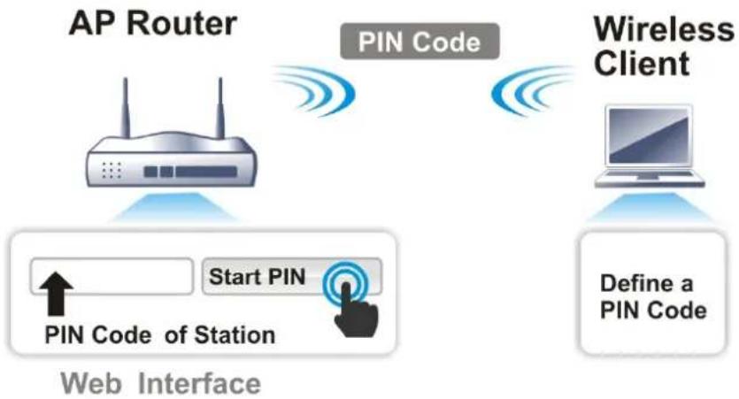
flowchart
graph TD
    A["AP Router"] --> B["PIN Code"]
    B --> C["Wireless Client"]
    C --> D["Define a PIN Code"]
    B --> E["Start PIN"]
    E --> F["PIN Code of Station"]
    F --> G["Web Interface"]
For WPS is supported in WPA-PSK or WPA2-PSK mode, if you do not choose such mode in Wireless LAN>>Security, you will see the following message box.
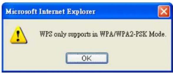
text_image
Microsoft Internet Explorer WPS only supports in WPA/WPA2-PSK Mode. OKPlease click OK and go back Wireless LAN>>Security to choose WPA-PSK or WPA2-PSK mode and access WPS again.
Web User Interface
Wizards
Quick Start Wizard
Service Activation Wizard
VPN Client Wizard
VPN Server Wizard
Wireless Wizard
On Hoo Smith
Wireless LAN
General Setup
Security
Access Control
WPS
WDS
Advanced Setting
AP Discovery
Station List
NOMOTOM
III-1-1 Wireless Wizard
The wireless wizard allows you to configure settings specified for a host AP (for home use or internal use for a company) and specified for a guest AP (for any wireless clients accessing into Internet).
Follow the steps listed below:
-
Open Wizards>>Wireless Wizard.
-
The screen of wireless wizard will be shown as follows. This page will be used for internal users in a company or your home. Besides, the settings will change based on different model of VigorLTE 200 series. In this case, VigorLTE 200Ln is used as an example.
Wireless Wizard
Host AP Configuration
Wireless 2.4GHz Settings
Name:
DrayTek
Mode:
Mixed(11b+11g+11n)
Channel:
Channel 6, 2437MHz
Security Key:
Note:
The host AP configured here will be used for home or internal company use.

Available settings are explained as follows:
| Item | Description |
| Name Enter the SSID name | me of this router for wireless connection.The default name is defined with DrayTek. Change the name if required. |
| Mode At present, the router can connect to 11b Only, 11g Only,11n Only, Mixed (11b+11g), Mixed (11g+11n) and Mixed(11b+11g+11n) stations simultaneously. Simply choose Mixed | |
| (11b+11g+11n) mode. | |
| Mixed(11b+11g+11n)▼11b Only11g Only11n Only (2.4 GHz)Mixed(11b+11g)Mixed(11g+11n)Mixed(11b+11g+11n) | |
| Channel Means the channel of frequency of the wireless LAN. The default channel is 6. You may switch channel if the selected channel is under serious interference. If you have no idea of choosing the frequency, please select Auto to let system determine for you. | |
| Security Key The wireless mode offered by this wizard is WPA2/ PSK.The WPA encrypts each frame transmitted from the radio using the key, which either PSK (Pre-Shared Key) entered manually in this field below or automatically negotiated via 802.1x authentication.Either 8~63 ASCII characters, such as 012345678(or 64 Hexadecimal digits leading by 0x, such as “0x321253abcde...”). | |
| Next Click it to get into the next setting page. | |
| Cancel Exit the wireless wizard without saving any changes. | |
- After typing the required information, click Next. The settings in the page limit the wireless station (guest) accessing into Internet but not being allowed to share the LAN network and VPN connection.
Wireless Wizard
Guest AP Configuration

text_image
Wireless 2.4GHz Settings ○Enable ●Disable SSID: DrayTek_Guest Security Key: Rate Control: □ Enable Upload 30000 kbps Download 30000 kbps Note: The configured guest AP will not be able to access the LAN network, VPN connections, or communicate with wireless devices connecting to the router's other APs. This AP interface shall be used for Internet access only.
Available settings are explained as follows:
| Item | Description |
| Enable/Disable Click it to enable or disable settings in this page. | |
| SSID Enter the SSID name of this router. (SSID1) | |
| Security Key The wireless mode offered by this wizard is WPA2/ PSK.The WPA encrypts each frame transmitted from the radio using the key, which either PSK (Pre-Shared Key) entered | |
| manually in this field below or automatically negotiated via 802.1x authentication.Either 8~63 ASCII characters, such as 012345678(or 64 Hexadecimal digits leading by 0x, such as "0x321253abcde..."). | |
| Rate Control Check the | box to enable the rate control function.Upload / Download - Enter the values as the limits for data upload and data download. |
| Next Click it to get into | the next setting page. |
| Cancel Exit the wireless | wizard without saving any changes. |
-
After typing the required information, click Next.
-
The following page will display the configuration summary for wireless setting.
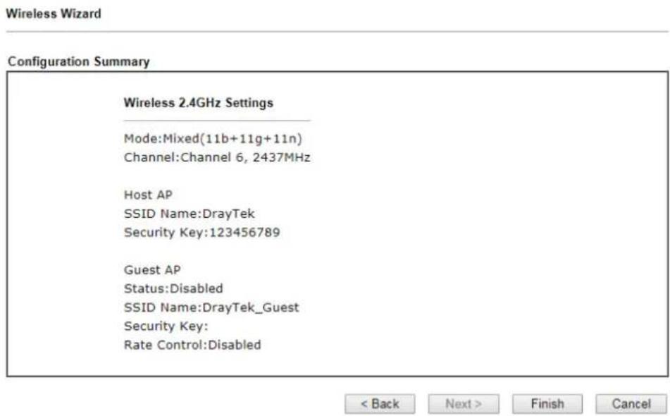
text_image
Wireless Wizard Configuration Summary Wireless 2.4GHz Settings Mode:Mixed(11b+11g+11n) Channel:Channel 6, 2437MHz Host AP SSID Name:DrayTek Security Key:123456789 Guest AP Status:Disabled SSID Name:DrayTek_Guest Security Key: Rate Control:Disabled < Back Next > Finish Cancel- Click Finish to complete the wireless settings configuration.
III-1-2 General Setup
By clicking the Wireless LAN>>General Setup, a new web page will appear so that you could configure the SSID and the wireless channel. Please refer to the following figure for more information.
Wireless LAN >> General Setup
General Setting ( IEEE 802.11 )
Enable Wireless LAN
Radio
Mode Channel
Mixed(11b+11g+11n) Channel 6, 2437MHz
SSID
| Index | Enable | SSID | Hide SSID | Isolate Member | Isolate VPN |
| 1 | DrayTek | ||||
| 2 | DrayTek_Guest | ||||
| 3 | Max: 31 characters | ||||
| 4 | Max: 31 characters |
Rate Control
| SSID | Enable | Upload Limit(kbps) | Download Limit(kbps) |
| 1 | 30000 | 30000 | |
| 2 | 30000 | 30000 | |
| 3 | 30000 | 30000 | |
| 4 | 30000 | 30000 |
Schedule
Schedule 1
Schedule 2
Schedule 3
Schedule 4
Schedule Profile
Available settings are explained as follows:
| Item | Description |
| Enable Wireless LAN Check | the box to enable wireless function. |
| Mode For 2.4GHz: At present | , the router can connect to 11b Only, 11g Only, 11n Only(2.4 GHz), Mixed (11b+11g), Mixed (11g+11n), and Mixed (11b+11g+11n) stations simultaneously. Simply choose Mixed (11b+11g+11n) mode. |
| Channel Means the channel | of frequency of the wireless LAN. The default channel is 6. You may switch channel if the selected channel is under serious interference. If you have no idea of choosing the frequency, please select Auto to let system determine for you. |
| SSID | Means the identification of the wireless LAN. SSID can be any text numbers or various special characters. |
| Hide SSID | Check it to prevent from wireless sniffing and make it harder for unauthorized clients or STAs to join your wireless LAN.Depending on the wireless utility, the user may only see the information except SSID or just cannot see any thing about Vigor wireless router while site surveying. The system allows you to set four sets of SSID for different usage. In default, the first set of SSID will be enabled. You can hide it for your necessity. |
| Isolate | Member -Check this box to make the wireless clients (stations) with the same SSID not accessing for each other.VPN - Check this box to make the wireless clients (stations) with different VPN not accessing for each other. |
| Rate Control Enable - Check | the box to set the rate limit for data transmission in upload and download.It controls the data transmission rate through wireless connection.Upload - Check Enable and enter the transmitting rate for data upload. Default value is 30,000 kbps.Download - Enter the transmitting rate for data download. Default value is 30,000 kbps. |
| Schedule Profile Set the wireless LAN to work at certain time interval only.You may choose up to 4 schedules out of the 15 schedules pre-defined inApplications >> Schedule setup. The default setting of this field is blank and the function will always work. | |
After finishing all the settings here, please click OK to save the configuration.
III-1-3 Security
This page allows you to set security with different modes for SSID 1, 2, 3 and 4 respectively. After configuring the correct settings, please click OK to save and invoke it.
The password (PSK) of default security mode is provided and stated on the label pasted on the bottom of the router. For the wireless client who wants to access into Internet through such router, please input the default PSK value for connection.
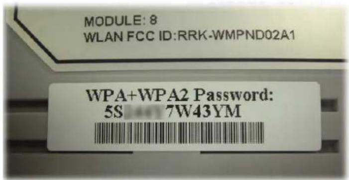
text_image
MODULE: 8 WLAN FCC ID:RRK-WMPND02A1 WPA+WPA2 Password: 5S 7W43YMBy clicking the Wireless LAN>>Security Settings, a new web page will appear so that you could configure the settings of WPA and WEP.
Wireless LAN >> Security Settings
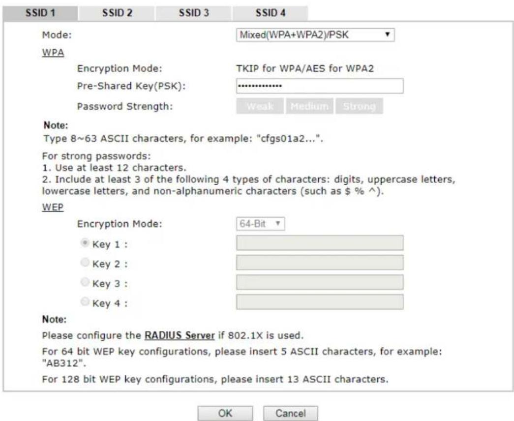
text_image
SSID 1 SSID 2 SSID 3 SSID 4 Mode: Mixed(WPA+WPA2)/PSK WPA Encryption Mode: TKIP for WPA/AES for WPA2 Pre-Shared Key(PSK): .......... Password Strength: Weak Medium Strong Note: Type 8~63 ASCII characters, for example: "cfgs01a2...". For strong passwords: 1. Use at least 12 characters. 2. Include at least 3 of the following 4 types of characters: digits, uppercase letters, lowercase letters, and non-alphanumeric characters (such as $ % ^). WEP Encryption Mode: 64-Bit Key 1 : Key 2 : Key 3 : Key 4 : Note: Please configure the RADIUS Server if 802.1X is used. For 64 bit WEP key configurations, please insert 5 ASCII characters, for example: "AB312". For 128 bit WEP key configurations, please insert 13 ASCII characters. OK CancelAvailable settings are explained as follows:
| Item | Description | |
| Mode | There are several modes provided for you to choose. | |
| Info | You should also set RADIUS Server simultaneously if 802.1x mode is selected. | |
| Disable - Turn off the encryption mechanism.WEP - Accepts only WEP clients and the encryption key should be entered in WEP Key.WEP/802.1x Only - Accepts only WEP clients and the encryption key is obtained dynamically from RADIUS server with 802.1X protocol.WPA/802.1x Only - Accepts only WPA clients and the encryption key is obtained dynamically from RADIUS server with 802.1X protocol.WPA2/802.1x Only - Accepts only WPA2 clients and the encryption key is obtained dynamically from RADIUS server with 802.1X protocol.Mixed (WPA+WPA2/802.1x only) - Accepts WPA and WPA2 clients simultaneously and the encryption key is obtained dynamically from RADIUS server with 802.1X protocol.WPA/PSK - Accepts only WPA clients and the encryption key should be entered in PSK.WPA2/PSK - Accepts only WPA2 clients and the encryption key should be entered in PSK.Mixed (WPA+ WPA2)/PSK - Accepts WPA and WPA2 clients simultaneously and the encryption key should be entered in PSK. | ||
| WPA | The WPA encrypts each frame transmitted from the radio using the key, which either PSK (Pre-Shared Key) entered manually in this field below or automatically negotiated via 802.1x authentication. Either 8~63 ASCII characters, such as 012345678(or 64 Hexadecimal digits leading by 0x, such as "0x321253abcde...").Pre-Shared Key (PSK) - Either 8~63 ASCII characters, such as 012345678..(or 64 Hexadecimal digits leading by 0x, such as "0x321253abcde...").Password Strength - The system will display the password strength (represented with the word of weak, medium or strong) of the PSK specified above. | |
| WEP | 64-Bit - For 64 bits WEP key, either 5 ASCII characters, such as 12345 (or 10 hexadecimal digitals leading by 0x, such as 0x4142434445.)128-Bit - For 128 bits WEP key, either 13 ASCII characters, such as ABCDEFGHIJKLM (or 26 hexadecimal digits leading by 0x, such as 0x4142434445464748494A4B4C4D).All wireless devices must support the same WEP encryption bit size and have the same key.Four keys can be entered here, but only one key can be selected at a time. The keys can be entered in ASCII or Hexadecimal. Check the key you wish to use. | |
After finishing all the settings here, please click OK to save the configuration.
III-1-4 Access Control
In the Access Control, the router may restrict wireless access to certain wireless clients only by locking their MAC address into a black or white list. The user may block wireless clients by inserting their MAC addresses into a black list, or only let them be able to connect by inserting their MAC addresses into a white list.
In the Access Control web page, users may configure the white/black list modes used by each SSID and the MAC addresses applied to their lists.
Wireless LAN >> Access Control
Access Control
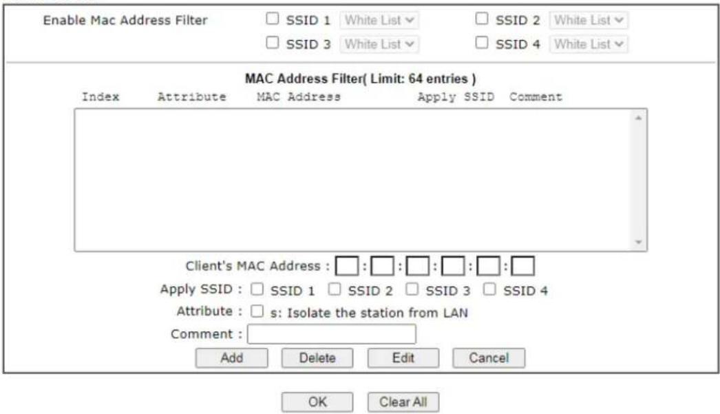
text_image
Enable Mac Address Filter □ SSID 1 White List □ SSID 2 White List □ SSID 3 White List □ SSID 4 White List MAC Address Filter( Limit: 64 entries ) Index Attribute MAC Address Apply SSID Comment Client's MAC Address : □: □: □: □: □: □ Apply SSID : □ SSID 1 □ SSID 2 □ SSID 3 □ SSID 4 Attribute : □ s: Isolate the station from LAN Comment : Add Delete Edit Cancel OK Clear All
Support AP ACL configuration file restoration.
Available settings are explained as follows:
| Item | Description |
| Enable Mac Address Filter | Select to enable the MAC Address filter for wireless LAN identified with SSID 1 to 4 respectively. All the clients (expressed by MAC addresses) listed in the box can be grouped under different wireless LAN. For example, they can be grouped under SSID 1 and SSID 2 at the same time if you check SSID 1 and SSID 2. |
| MAC Address Filter Display | all MAC addresses that are edited before. |
| Client's MAC Address Manually enter the MAC address of wireless client. | |
| Apply SSID After entering the client's MAC address, check the box of the SSIDs desired to insert this MAC address into their access control list. | |
| Attribute s: Isolate the station from LAN - select to isolate the wireless connection of the wireless client of the MAC address from LAN. | |
| Comment Enter a brief description for the specified client's MAC | |
| address. | |
| Add Add a new MAC address | into the list. |
| Delete Delete the selected MAC address in the list. | |
| Edit Edit the selected MAC address in the list. | |
| Cancel Give up the access control set up. | |
| OK Click it to save the access control list. | |
| Clear All Clean all entries in the MAC address list. | |
| Backup Access Control | Settings on this web page can be saved as a file which can be restored in the future by this device or other device. |
| Upload From File Restore wireless access control settings and applied onto this device. | |
After finishing all the settings here, please click OK to save the configuration.
III-1-5 WPS
Below shows Wireless LAN>>WPS web page:
Wireless LAN >> WPS (Wi-Fi Protected Setup)
Enable WPS
Wi-Fi Protected Setup Information
| WPS Status | Configured |
| SSID | DrayTek |
| Authentication Mode | WPA2/PSK |
Device Configure
| Configure via Push Button | Start PBC | |
| Configure via Client PinCode | Start PIN | |
Status: Ready
Note:
WPS can help your wireless client automatically connect to the Access point.
: WPS is Disabled.
Q: WPS is Enabled.
: Waiting for WPS requests from wireless clients.
Available settings are explained as follows:
| Item | Description |
| Enable WPS Check this box to enable WPS setting. | |
| WPS Status | Display related system information for WPS. If the wireless security (encryption) function of the router is properly configured, you can see ‘Configured’ message here. |
| SSID | Display the SSID1 of the router. WPS is supported by SSID1 only. |
| Authentication Mode Display current authentication mode of the router. Only WPA2/ PSK and WPA/ PSK support WPS. | |
| Configure via Push Button | Click Start PBC to invoke Push-Button style WPS setup procedure. The router will wait for WPS requests from wireless clients about two minutes. The WPS LED on the router will blink fast when WPS is in progress. It will return to normal condition after two minutes. (You need to setup WPS within two minutes) |
| Configure via Client PinCode | Please input the PIN code specified in wireless client you wish to connect, and click Start PIN button. The WPS LED on the router will blink fast when WPS is in progress. It will return to normal condition after two minutes. (You need to setup WPS within two minutes) |
III-1-6 WDS
WDS means Wireless Distribution System. It is a protocol for connecting two access points (AP) wirelessly. Usually, it can be used for the following application:
• Provide bridge traffic between two LANs through the air.
- Extend the coverage range of a WLAN.
Refer to the following table:
| WDS Mode | Wireless Signal | Comparisons |
| Bridge | Limited | ● Wireless stations (clients) within the effective range of wireless signal can access into Internet through the router / AP.● Wireless stations (clients) out of the effective range of wireless signal cannot access into Internet through the router / AP with Bridge mode configured.● The packets received from a WDS link will only be forwarded to local wired or wireless hosts. |
| Repeater | Extended | ● Wireless stations (clients) within the effective range of wireless signal can access into Internet through the router / AP.● Wireless stations (clients) out of the effective range of wireless signal can access into Internet through the router / AP with Repeater mode configured.● The packets received from one Vigor router can be repeated to another AP (remotely) through WDS links.● Only Repeater mode can do WDS-to-WDS packet forwarding. |
The WDS - Repeater mode is implemented in Vigor router. The application for the WDS-Repeater mode is depicted as below:
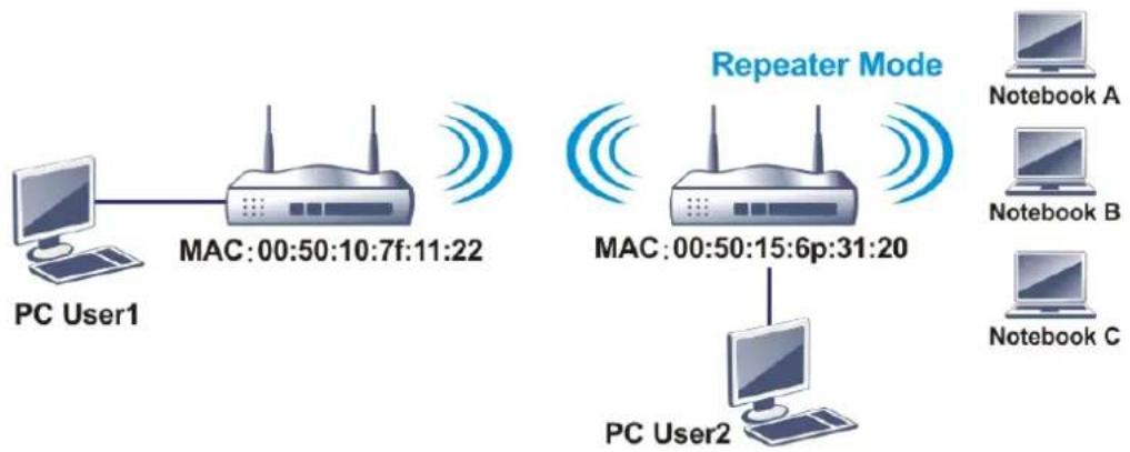
flowchart
graph TD
    PCUser1["PC User1"] --> MAC1["MAC:00:50:10:7f:11:22"]
    MAC1 --> MAC2["Repeater Mode"]
    MAC2 --> PCUser2["PC User2"]
    Notebooks_A["Notebook A"]
    Notebooks_B["Notebook B"]
    Notebooks_C["Notebook C"]
Click WDS from Wireless LAN menu. The following page will be shown.
WDS Settings
Set to Factory Default
| Mode: Disable▼ | BridgeEnable Peer MAC Address□ : □ : □ : □ : □ : □□ : □ : □ : □ : □ : □□ : □ : □ : □ : □ : □□ : □ : □ : □ : □ : □ |
| Security:● Disable ● WEP ● Pre-shared Key | |
| WEP:Use the same WEP key set inSecurity Settings. | |
| Pre-shared Key:Type:○ WPA ● WPA2Key :Max: 66 characters | |
| Note:WPA and WPA2 are not compatible with DrayTekWPA. | |
| Type 8~63 ASCII characters or 64 hexadecimaldigits leading by "0x", for example "cfgs01a2..."or "0x655abcd....". | |
| Note:The status is valid only when the peer alsosupports this function. |

Available settings are explained as follows:
| Item | Description |
| Mode | Choose the mode for WDS setting. Disable mode will not invoke any WDS setting. Repeater mode is for the second one. |
| Security | There are three types for security, Disable, WEP and Pre-shared key. The setting you choose here will make the following WEP or Pre-shared key field valid or not. Choose one of the types for the router. |
| Pre-shared Key | When Pre-Shared Key is selected as Security above, configure the following settings if required.Type - There are some types for you to choose. WPA and WPA2 are used for WDS devices (e.g. 2925n wireless router, you can set the encryption mode as WPA or WPA2 to establish your WDS system between AP and the router.Key - Set the encryption key in this field. Type 8 ~ 63 ASCII characters or 64 hexadecimal digits leading by “0x”. |
| Bridge | If you choose Bridge as the connecting mode, please Enter the peer MAC address in these fields. Four peer MAC addresses are allowed to be entered in this page at one time. Yet please disable the unused link to get betterperformance. If you want to invoke the peer MAC address, remember to check Enable box in the front of the MAC address after typing. |
| Repeater | If you choose Repeater as the connecting mode, please Enter the peer MAC address (of VigorAP/ Vigor router required to make connection with such Vigor router and used to extend the wireless signal) in these fields.Four peer MAC addresses are allowed to be entered in this page at one time. Similarly, if you want to invoke the peer MAC address, remember to check Enable box in the front of the MAC address after typing. |
| Access Point Function | Click Enable to make this router serve as an access point.When Repeater is set as WDS Mode, click Enable to use such function.Click Disable if Bridge is set as WDS Mode. |
| Status | It allows user to send “hello” message to peers. Yet, it is valid only when the peer also supports this function. |
After finishing all the settings here, please click OK to save the configuration.
III-1-7 Advanced Setting
This page allows users to set advanced settings such as operation mode, channel bandwidth, guard interval, and aggregation MSDU for wireless data transmission.
Wireless LAN >> Advanced Setting
HT Physical Mode
| Operation Mode | Mixed Mode ○ Green Field |
| Channel Bandwidth | 20 20/40 40 |
| Guard Interval | long auto |
| Aggregation MSDU(A-MSDU) | Enable Disable |
| Long Preamble | Enable Disable |
| Packet-OVERDRIVETM TX Burst | Enable Disable |
| Tx Power | 100% 80% 60% 30% 20% 10% |
| WMM Capable | Enable Disable |
| APSD Capable | Enable Disable |
| Rate Adaptation Algorithm | New Old |
| Fragment Length (256 - 2346) | 2346 bytes |
| RTS Threshold (1 - 2347) | 2347 bytes |
| Country Code | ( Reference) |
OK
Available settings are explained as follows:
| Item | Description |
| Operation Mode | Mixed Mode - the router can transmit data with the ways supported in both 802.11a/ b/ g and 802.11n standards.However, the entire wireless transmission will be slowed down if 802.11g or 802.11b wireless client is connected.Green Field - to get the highest throughput, please choose such mode. Such mode can make the data transmission happen between 11n systems only. In addition, it does not have protection mechanism to avoid the conflict with neighboring devices of 802.11a/ b/ g. |
| Channel Bandwidth | Vigor router will use 20MHz/ 40MHz/ 80MHz for data transmission and receiving between the AP and the stations.20/40- Vigor Router will scan for nearby wireless AP, and then use 20MHz if the number of AP is more than 10, or use 40MHz if it's not. |
| Guard Interval It is to assure | the safety of propagation delays and reflections for the sensitive digital data. If you choose auto as guard interval, the AP router will choose short guard interval (increasing the wireless performance) or long guard interval for data transmit based on the station capability. |
| Aggregation MSDU | Aggregation MSDU can combine frames with different sizes. It is used for improving MAC layer's performance for some brand's clients. The default setting is Enable. |
| Long Preamble This option | is to define the length of the sync field in an 802.11 packet. Most modern wireless network uses short preamble with 56 bit sync field instead of long preamble with 128 bit sync field. However, some original 11b wireless network devices only support long preamble. Click Enable touse Long Preamble if needed to communicate with this kind of devices. |
| Packet-OVERDRIVE TX Burst | This feature can enhance the performance in data transmission about 40%* more (by checking Tx Burst). It is active only when both sides of Access Point and Station (in wireless client) invoke this function at the same time. That is, the wireless client must support this feature and invoke the function, too.Note: Vigor N61 wireless adapter supports this function. Therefore, you can use and install it into your PC for matching with Packet-OVERDRIVE (refer to the following picture of Vigor N61 wireless utility window, choose Enable for TxBURST on the tab of Option).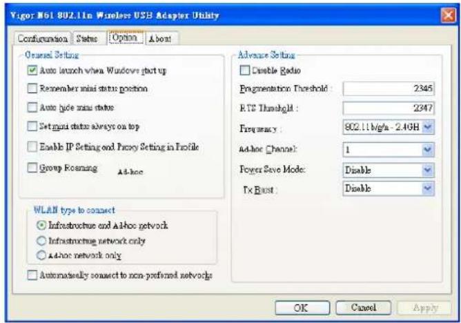 |
| TX Power | Set the power percentage for transmission signal of access point. The greater the value is, the higher intensity of the signal will be. |
| WMM Capable WMM is an ab | breviation of Wi-Fi Multimedia. It defines the priority levels for four access categories derived from 802.1d (prioritization tabs). The categories are designed with specific types of traffic, voice, video, best effort and low priority data. There are four accessing categories - AC_BE , AC_BK, AC_VI and AC_VO for WMM.To apply WMM parameters for wireless data transmission, please click theEnableradio button. |
| APSD Capable | APSD (automatic power-save delivery) is an enhancement over the power-save mechanisms supported by Wi-Fi networks. It allows devices to take more time in sleeping state and consume less power to improve the performance by minimizing transmission latency.The default setting isDisable. |
| Rate Adaptation Algorithm | Wireless transmission rate is adapted dynamically. Usually, performance of “new” algorithm is better than “old”. |
| Fragment Length(256 - 2346) | Set the Fragment threshold. Do not modify default value if you don’t know what it is, default value is 2346. |
| RTS Threshold (1 - 2347) | Minimize the collision (unit is bytes) between hidden stations to improve wireless performance.Set the RTS threshold. Do not modify default value if you don’t know what it is, default value is 2347. |
| Country Code | Vigor router broadcasts country codes by following the 802.11d standard. However, some wireless stations will detect / scan the country code to prevent conflict occurred. If conflict is detected, wireless station will be warned and is unable to make network connection. Therefore, changing the country code to ensure successful network connection will be necessary for some clients. |
After finishing all the settings here, please click OK to save the configuration.
III-1-8 AP Discovery
Vigor router can scan all regulatory channels and find working APs in the neighborhood. Based on the scanning result, users will know which channel is clean for usage. Also, it can be used to facilitate finding an AP for a WDS link. Notice that during the scanning process (about 5 seconds), no client is allowed to connect to Vigor.
This page is used to scan the existence of the APs on the wireless LAN. Yet, only the AP which is in the same channel of this router can be found. Please click Scan to discover all the connected APs.
Wireless LAN >> Access Point Discovery
Access Point List
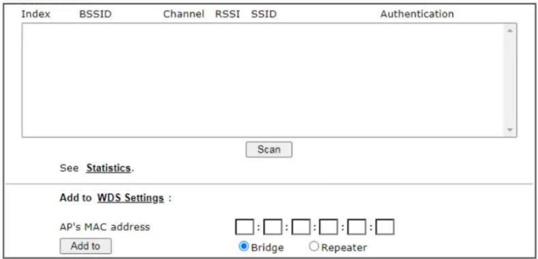
text_image
Index BSSID Channel RSSI SSID Authentication Scan See Statistics. Add to WDS Settings : AP's MAC address : : : : : : : : Add to Bridge RepeaterNote:
- During the scanning process (\~5 seconds), no station is allowed to connect with the router.
- AP Discovery can only support up to 32 APs displayed on the screen.
Available settings are explained as follows:
| Item | Description |
| Scan It is used to discover all | the connected AP. The results will be shown on the box above this button. |
| Statistics | It displays the statistics for the channels used by APs.Wireless LAN >> Site Survey Statistics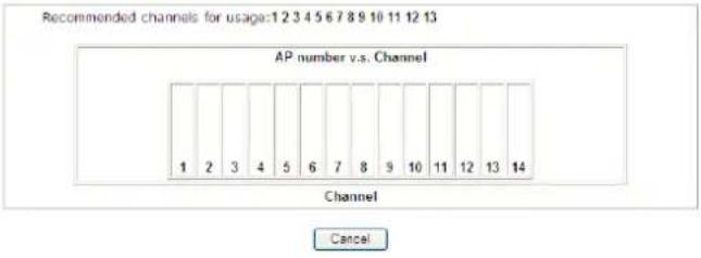 |
| Add to If you want the found | AP applying the WDS settings, pleaseEnter the AP's MAC address on the bottom of the page and click Repeater. Next, click Add to. Later, the MAC address of the AP will be added to Bridge or Repeater field of WDS settings page. |
III-1-9 Station List
Station List provides the knowledge of connecting wireless clients now along with its status code. There is a code summary below for explanation. For convenient Access Control, you can select a WLAN station and click Add to Access Control below.
Wireless LAN >> Station List
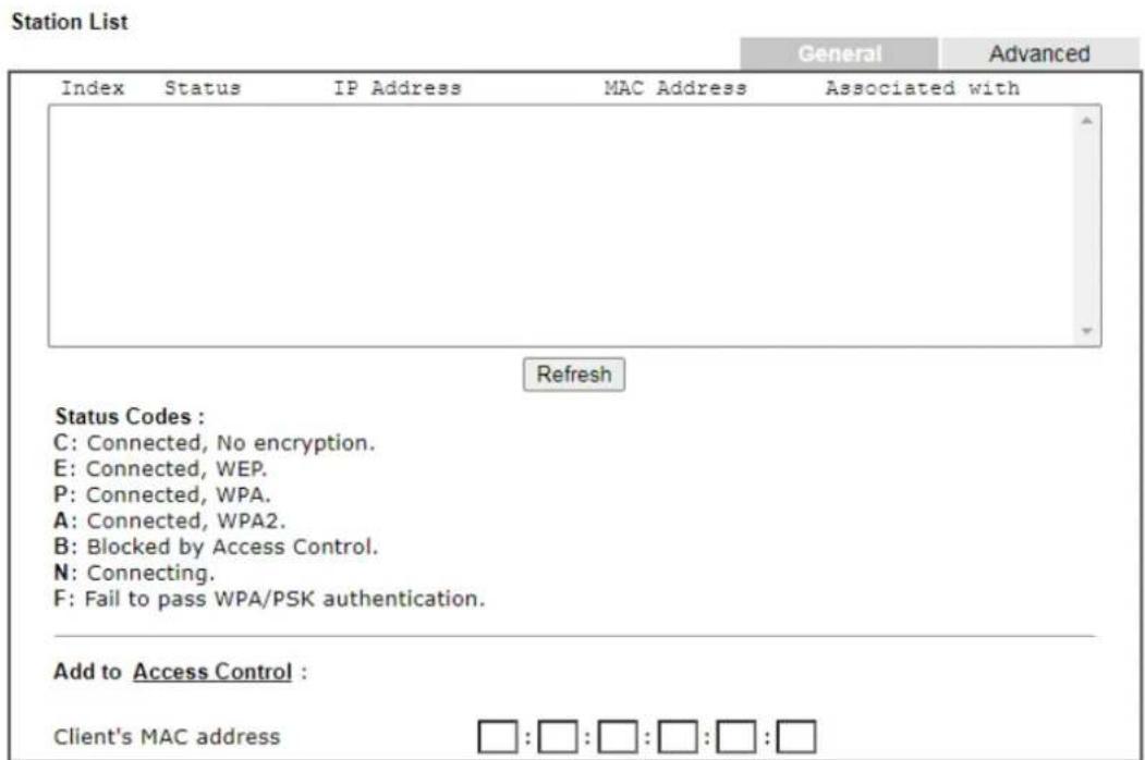
text_image
Station List General Advanced Index Status IP Address MAC Address Associated with Refresh Status Codes : C: Connected, No encryption. E: Connected, WEP. P: Connected, WPA. A: Connected, WPA2. B: Blocked by Access Control. N: Connecting. F: Fail to pass WPA/PSK authentication. Add to Access Control : Client's MAC address : : : : : : : : : :Note:
After a station connects to the router successfully, it may be turned off without notice. In that case, it will still be on the list until the connection expires.
Add
Available settings are explained as follows:
| Item | Description |
| Refresh Click this button to | refresh the status of station list. |
| Add Click this button to add | current typed MAC address into Access Control. |
This page is left blank.
Part IV VPN

VPN
A Virtual Private Network (VPN) is the extension of a private network that encompasses links across shared or public networks like the Internet. In short, by VPN technology, you can send data between two computers across a shared or public network in a manner that emulates the properties of a point-to-point private link.

SSL VPN
It is a form of VPN that can be used with a standard Web browser.

Certificate Management
A digital certificate works as an electronic ID, which is issued by a certification authority (CA). It contains information such as your name, a serial number, expiration dates etc., and the digital signature of the certificate-issuing authority so that a recipient can verify that the certificate is real. Here Vigor router support digital certificates conforming to standard X.509.
IV-1 VPN and Remote Access
A Virtual Private Network (VPN) is the extension of a private network that encompasses links across shared or public networks like the Internet. In short, by VPN technology, you can send data between two computers across a shared or public network in a manner that emulates the properties of a point-to-point private link.
The VPN built is suitable for:
● Communication between home office and customer
- Secure connection between Teleworker, staff on business trip and main office
● Exchange data between remote office and main office
● POS between chain store and headquarters
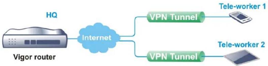
flowchart
graph LR
    A["HQ"] --> B["Internet"]
    B --> C["VPN Tunnel"]
    B --> D["VPN Tunnel"]
    C --> E["Tele-worker 1"]
    D --> F["Tele-worker 2"]
Site-to-Site (LAN-to-LAN)
- A connection between two router's LAN networks.
- Allows employees in branch offices and head office to share the same network resources.

flowchart
graph LR
    A["Local Network 192.168.1.0/24"] --> B["Network"]
    B --> C["Internet"]
    C --> D["Remote Network 172.16.2.0/24"]
    B --> E["VPN Tunnel"]
Remote Access (Remote Dial-in)
- A connection between the remote host and router's LAN network. The host will use an IP address in the local subnet.
- Allows employees to access the company's internal resources when they are traveling.

flowchart
graph LR
    A["Local Network 192.168.1.0/24"] --> B["Internet VPN Tunnel"]
    B --> C["Remote Host 192.168.1.100"]
Web User Interface
Wizards
Quick Start Wizard
Service Activation Wizard
VPN Client Wizard
VPN Server Wizard
Wireless Wizard
VPN and Remote Access
Remote Access Control
PPP General Setup
IPsec General Setup
IPsec Peer Identity
Remote Dial-in User
LAN to LAN
Connection Management
N-1-1 VPN Client Wizard
Such wizard is used to configure VPN settings for VPN client. Such wizard will guide to set the LAN-to-LAN profile for VPN dial out connection (from server to client) step by step.
- Open Wizards>>VPN Client Wizard. The following page will appear.
VPN Client Wizard
Choose VPN Establishment Environment
LAN-to-LAN VPN Client Mode Selection:
Route Mode
Please choose a LAN-to-LAN Profile:
[Index] [Status] [Name]
Note:
- Please use Route Mode for typical LAN-to-LAN tunnels.
- If the remote network is only expecting a single client or IP and is not configured to route the subnet then select NAT Mode.
- If you are unsure of your configuration select Route Mode.
< Back Next > Finish Cancel
Available settings are explained as follows:
| Item | Description |
| LAN-to-LAN Client Mode Selection | Choose the client mode.Route Mode/NAT Mode – If the remote network only allows you to dial in with single IP, please choose NAT mode, otherwise please choose Route Mode. |
| Please choose a LAN-to-LAN Profile | There are 32 VPN profiles for users to set. |
- When you finish the mode and profile selection, please click Next to open the following page.
VPN Client Wizard
VPN Connection Setting
Security Ranking:
Very High
L2TP over IPSec
High
IPSec / SSL
Medium
PPTP (Encryption)
Low
L2TP / PPTP (None Encryption)
Throughput Ranking:
Very High
L2TP / PPTP (None Encryption)
High
IPSec
Medium
L2TP over IPSec / PPTP (Encryption)
Low
SSL
Select VPN Type:
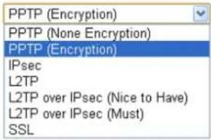
text_image
PPTP (Encryption) PPTP (None Encryption) PPTP (Encryption) IPsec L2TP L2TP over IPsec (Nice to Have) L2TP over IPsec (Must) SSL< Back
Next >
Finish
Cancel
In this page, you have to select suitable VPN type for the VPN client profile. There are six types provided here. Different type will lead to different configuration page. After making the choices for the client profile, please click Next. You will see different configurations based on the selection(s) you made.

Info
The following descriptions for VPN Type are based on the Route Mode specified in LAN-to-LAN Client Mode Selection.
When you choose PPTP (None Encryption) or PPTP (Encryption), you will see the following graphic:
VPN Client Wizard
VPN Client PPTP Encryption Settings
| Profile Name | ??? |
| VPN Dial-Out Through | WAN2 First |
| □ Always on | |
| Server IP/Host Name for VPN(e.g. draytek.com or 123.45.67.89) | |
| Username | ??? |
| Password | |
| Remote Network IP | 0.0.0.0 |
| Remote Network Mask | 255.255.255.0 / 24 |
| Local Network IP | 192.168.1.60 |
| Local Network Mask | 255.255.255.0 / 24 |
When you choose IPsec, you will see the following graphic:
VPN Client Wizard
VPN Client IPsec Settings
| Profile Name | ??? |
| VPN Dial-Out Through | WAN2 First |
| □ Always on | |
| Server IP/Host Name for VPN(e.g. draytek.com or 123.45.67.89) | 123.45.67.89 |
| IKE Authentication Method | |
| ● Pre-Shared Key | |
| Confirm Pre-Shared Key | |
| ○ Digital Signature (X.509) | |
| Peer ID | None |
| Local ID | |
| ● Alternative Subject Name First | |
| ○ Subject Name First | |
| Local Certificate | None |
| IPsec Security Method | |
| ○ Medium (AH) | |
| ● High (ESP) | AES with Authentication |
| Remote Network IP | 0.0.0.0 |
| Remote Network Mask | 255.255.255.0 / 24 |
| Local Network IP | 192.168.1.60 |
| Local Network Mask | 255.255.255.0 / 24 |
When you choose SSL, you will see the following graphic:
VPN Client Wizard
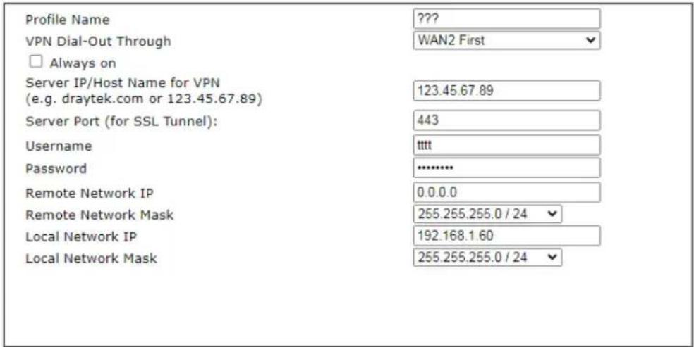
text_image
Profile Name ??? VPN Dial-Out Through WAN2 First □ Always on Server IP/Host Name for VPN 123.45.67.89 (e.g. draytek.com or 123.45.67.89) Server Port (for SSL Tunnel): Username 443 Password **** Remote Network IP 0.0.0.0 Remote Network Mask 255.255.255.0 / 24 Local Network IP 192.168.1.60 Local Network Mask 255.255.255.0 / 24
When you choose L2TP over IPsec (Nice to Have) or L2TP over IPsec (Must), you will see the following graphic:
VPN Client Wizard
VPN Client L2TP over IPsec (Nice to Have) Settings
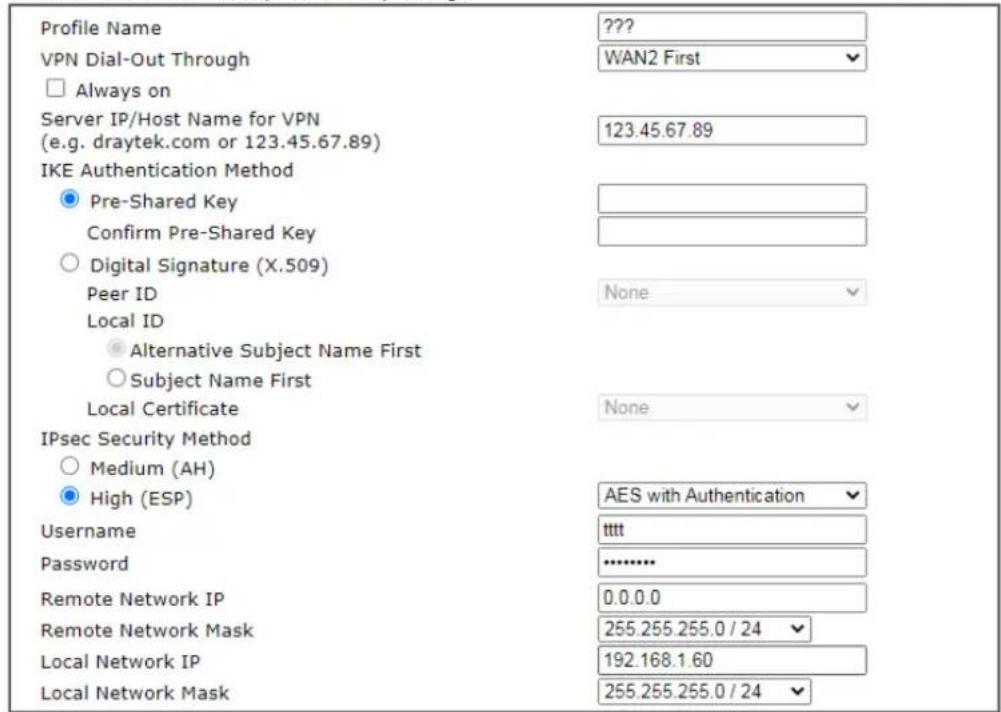
text_image
Profile Name ??? VPN Dial-Out Through WAN2 First □ Always on Server IP/Host Name for VPN (e.g. draytek.com or 123.45.67.89) 123.45.67.89 IKE Authentication Method ● Pre-Shared Key Confirm Pre-Shared Key ○ Digital Signature (X.509) Peer ID None Local ID ● Alternative Subject Name First ○ Subject Name First Local Certificate None IPsec Security Method ○ Medium (AH) ● High (ESP) AES with Authentication Username ttttt Password .......... Remote Network IP 0.0.0.0 Remote Network Mask 255.255.255.0 / 24 Local Network IP 192.168.1.60 Local Network Mask 255.255.255.0 / 24
Available settings are explained as follows:
| Item | Description |
| Profile Name | Type a name for such profile. The length of the file is limitedto 10 characters. |
| Always On | Check to enable router always keep VPN connection. |
| Server IP/Host Name for VPN | Enter the IP address of the server or Enter the host name for such VPN profile. |
| IKE Authentication Method | IKE Authentication Method usually applies to those are remote dial-in user or node (LAN to LAN) which uses dynamic IP address and IPsec-related VPN connections such as L2TP over IPsec and IPsec tunnel.Pre-Shared Key- Specify a key for IKE authentication.Confirm Pre-Shared Key-Confirm the pre-shared key. |
| Digital Signature (X.509) | Click Digital Signature to invoke this function.Peer ID - Choose the peer ID selection from the drop down list.Local ID - Choose Alternative Subject Name First or Subject Name First.Local Certificate - Use the drop down list to choose one of the certificates for using. You have to configure one certificate at least previously in Certificate Management >>Local Certificate. Otherwise, the setting you choose here will not be effective. |
| IPsec Security Method | Medium - Authentication Header (AH) means data will be authenticated, but not be encrypted. By default, this option is active.High - Encapsulating Security Payload (ESP) means payload (data) will be encrypted and authenticated. You may select encryption algorithm from Data Encryption Standard (DES), Triple DES (3DES), and AES. |
| User Name | This field is used to authenticate for connection when you select PPTP or L2TP with or without IPsec policy above.The length of the user name is limited to 11 characters. |
| Password | This field is used to authenticate for connection when you select PPTP or L2TP with or without IPsec policy above.The length of the password is limited to 11 characters. |
| Remote Network IP Please type one LAN IP address (according to the real location of the remote host) for building VPN connection. | |
| Remote Network Mask | Please Enter the network mask (according to the real location of the remote host) for building VPN connection. |
| Local Network IP Enter | the local network IP for TCP / IP configuration. |
| Local Network Mask Enter | the local network mask for TCP / IP configuration. |
- After finishing the configuration, please click Next. The confirmation page will be shown as follows. If there is no problem, you can click one of the radio buttons listed on the page and click Finish to execute the next action.
Please confirm your settings
| LAN-to-LAN Index: | 1 |
| Profile Name: | ??? |
| VPN Connection Type: | L2TP over IPsec (Nice to Have) |
| VPN Dial-Out Through: | WAN2 First |
| Always on: | No |
| Server IP/Host Name: | 123.45.67.89 |
| IKE Authentication Method: | Pre-Shared Key |
| IPsec Security Method: | AES with Authentication |
| Remote Network IP: | 0.0.0.0 |
| Remote Network Mask: | 255.255.255.0 |
| Local Network IP: | 192.168.1.60 |
| Local Network Mask: | 255.255.255.0 |
| < Back | Next > | Finish | Cancel |
Available settings are explained as follows:
| Item | Description |
| Go to the VPN Connection Management | Click this radio button to access VPN and Remote Access>>Connection Management for viewing VPN Connection status. |
| Do another VPN Server Wizard Setup | Click this radio button to set another profile of VPN Server through VPN Server Wizard. |
| View more detailed configuration | Click this radio button to access VPN and Remote Access>>LAN to LAN for viewing detailed configuration. |
IV-1-2 VPN Server Wizard
Such wizard is used to configure VPN settings for VPN server. Such wizard will guide to set the LAN-to-LAN profile for VPN dial in connection (from client to server) step by step.
- Open Wizards>>VPN Server Wizard. The following page will appear.
VPN Server Wizard
Choose VPN Establishment Environment
VPN Server Mode Selection:
Please choose a LAN-to-LAN Profile:
Please choose a Dial-in User Accounts:
Allowed Dial-in Type:
Remote Dial-in User (Teleworker)
[Index] [Status] [Name]
1 x ???
PPTP
IPsec
L2TP with IPsec Policy None
SSL Tunnel

Available settings are explained as follows:
| Item | Description |
| VPN Server Mode Selection | Choose the direction for the VPN server.Site to Site VPN - To set a LAN-to-LAN profile automatically, please choose Site to Site VPN.Remote Dial-in User -You can manage remote access by maintaining a table of remote user profile, so that users can be authenticated to dial-in via VPN connection. |
| Please choose a LAN-to-LAN Profile | This item is available when you choose Site to Site VPN (LAN-to-LAN) as VPN server mode. There are 32 VPN profiles for users to set. |
| Please choose a Dial-in User Accounts | This item is available when you choose Remote Dial-in User (Teleworker) as VPN server mode. There are 32 VPN tunnels for users to set. |
| Allowed Dial-in Type | This item is available after you choose any one of dial-in user account profiles. Next, you have to select suitable dial-in type for the VPN server profile. There are several types provided here (similar to VPN Client Wizard).Different Dial-in Type will lead to different configuration page. In addition, adjustable items for each dial-in type will be changed according to the VPN Server Mode (Site to Site VPN and Remote Dial-in User) selected. |
- After making the choices for the server profile, please click Next. You will see different configurations based on the selection you made. Here we take the examples of choosing Site-to-Site VPN as the VPN Server Mode.
When you check PPTP/SSL, you will see the following graphic:
VPN Server Wizard
VPN Authentication Setting
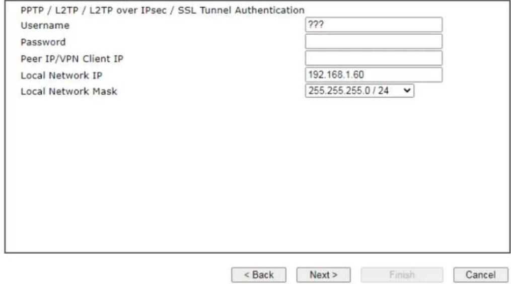
text_image
PPTP / L2TP / L2TP over IPsec / SSL Tunnel Authentication Username ??? Password Peer IP/VPN Client IP Local Network IP 192.168.1.60 Local Network Mask 255.255.255.0 / 24 < Back Next > Finish CancelWhen you check PPTP & IPsec & L2TP (three types) or PPTP & IPsec (two types) or L2TP with Policy (Nice to Have/Must), you will see the following graphic:
VPN Server Wizard
VPN Authentication Setting
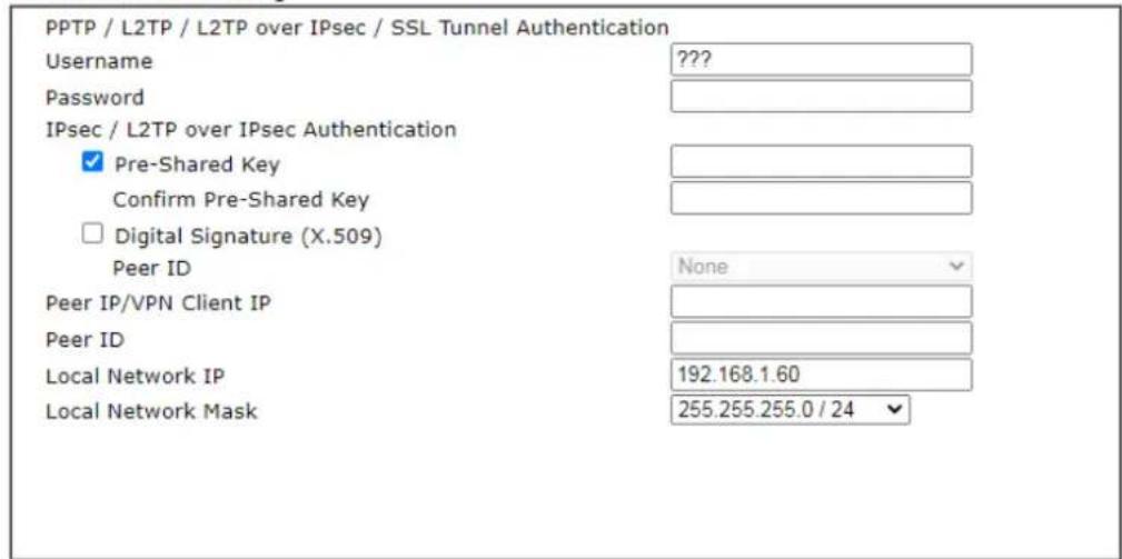
text_image
PPTP / L2TP / L2TP over IPsec / SSL Tunnel Authentication Username ??? Password IPsec / L2TP over IPsec Authentication ✓ Pre-Shared Key Confirm Pre-Shared Key □ Digital Signature (X.509) Peer ID None Peer IP/VPN Client IP Peer ID Local Network IP 192.168.1.60 Local Network Mask 255.255.255.0 / 24
When you check IPsec, you will see the following graphic:
VPN Server Wizard
VPN Authentication Setting
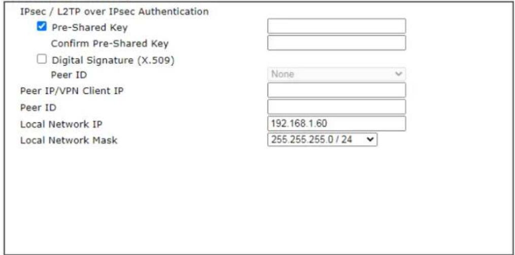
text_image
IPsec / L2TP over IPsec Authentication ✓ Pre-Shared Key Confirm Pre-Shared Key □ Digital Signature (X.509) Peer ID Peer IP/VPN Client IP Peer ID Local Network IP 192.168.1.60 Local Network Mask None 255.255.255.0 / 24
Available settings are explained as follows:
| Item | Description |
| User Name | This field is used to authenticate for connection when you select PPTP or L2TP with or without IPsec policy above.The length of the name is limited to 11 characters. |
| Password | This field is used to authenticate for connection when you select PPTP or L2TP with or without IPsec policy above.The length of the name is limited to 11 characters. |
| Pre-Shared Key For IPsec/ L2TP IPsec authentication, you have to type a pre-shared key.The length of the name is limited to 64 characters. | |
| Confirm Pre-Shared Key | Enter the pre-shared key again for confirmation. |
| Digital Signature (X.509) | Check the box of Digital Signature to invoke this function.Peer ID - Choose the peer ID selection from the drop down list.Local ID - Choose Alternative Subject Name First or Subject Name First. |
| Peer IP/VPN Client IP Enter the WAN IP address or VPN client IP address for the remote client. | |
| Peer ID Enter the ID name for the remote client.The length of the name is limited to 47 characters. | |
| Remote Network IP | It is available for Site to Site VPN (LAN-to-LAN).Please type one LAN IP address (according to the real location of the remote host) for building VPN connection. |
| Remote Network Mask | It is available for Site to Site VPN (LAN-to-LAN).Please Enter the network mask (according to the reallocation of the remote host) for building VPN connection. |
| Local Network IP Enter | the local network IP for TCP / IP configuration. |
| Local Network Mask Enter | the local network mask for TCP / IP configuration. |
- After finishing the configuration, please click Next. The confirmation page will be shown as follows. If there is no problem, you can click one of the radio buttons listed on the page and click Finish to execute the next action.
VPN Server Wizard
Please Confirm Your Settings
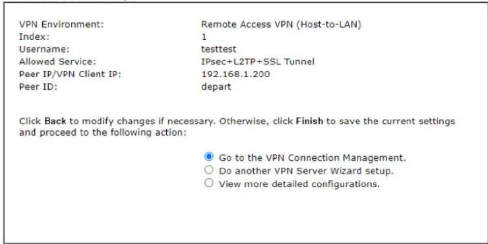
text_image
VPN Environment: Remote Access VPN (Host-to-LAN) Index: 1 Username: testtest Allowed Service: IPsec+L2TP+SSL Tunnel Peer IP/VPN Client IP: 192.168.1.200 Peer ID: depart Click Back to modify changes if necessary. Otherwise, click Finish to save the current settings and proceed to the following action: Go to the VPN Connection Management. Do another VPN Server Wizard setup. View more detailed configurations.
Available settings are explained as follows:
| Item | Description |
| Go to the VPN Connection Management | Click this radio button to access VPN and Remote Access>>Connection Management for viewing VPN Connection status. |
| Do another VPN Server Wizard Setup | Click this radio button to set another profile of VPN Server through VPN Server Wizard. |
| View more detailed configuration | Click this radio button to access VPN and Remote Access>>LAN to LAN for viewing detailed configuration. |
IV-1-3 Remote Access Control
Enable the necessary VPN service as you need. If you intend to run a VPN server inside your LAN, you should disable the VPN service of Vigor Router to allow VPN tunnel pass through, as well as the appropriate NAT settings, such as DMZ or open port.
Open VPN and Remote Access>>Remote Access Control.
Remote Access Control Setup
□ Enable PPTP VPN Service
Enable IPSec VPN Service
Enable L2TP VPN Service
Enable SSL VPN Service
√ Enable OpenVPN Service
Note:
To allow VPN pass-through to a separate VPN server on the LAN, disable any services above that use the same protocol and ensure that NAT Open Ports or Port Redirection is also configured.

After finishing all the settings here, please click OK to save the configuration.
IV-1-4 PPP General Setup
This submenu only applies to PPP-related VPN connections, such as PPTP, L2TP, L2TP over IPsec.
VPN and Remote Access >> PPP General Setup
PPP General Setup
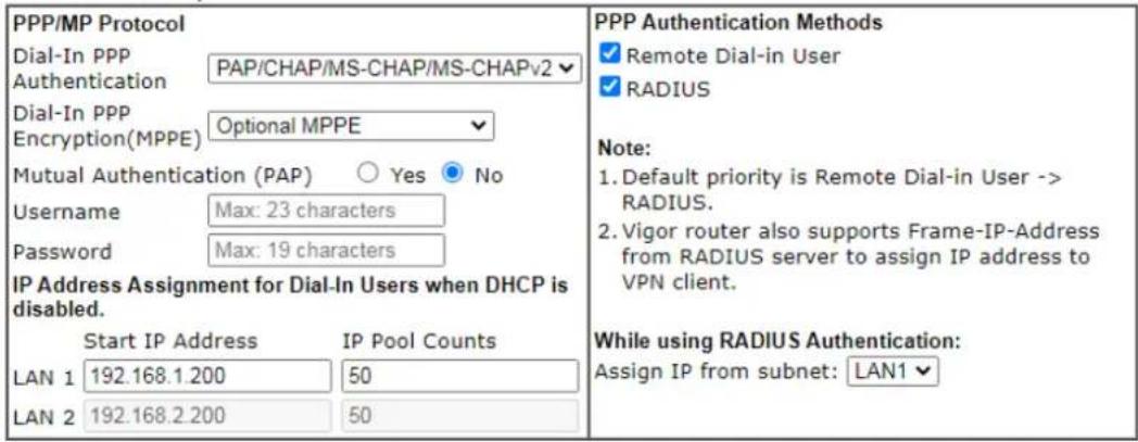
text_image
PPP/MP Protocol Dial-In PPP PAP/CHAP/MS-CHAP/MS-CHAPv2 Authentication Dial-In PPP Optional MPPE Encryption(MPPE) Mutual Authentication (PAP) ○ Yes ● No Username Max: 23 characters Password Max: 19 characters IP Address Assignment for Dial-In Users when DHCP is disabled. Start IP Address IP Pool Counts LAN 1 192.168.1.200 50 LAN 2 192.168.2.200 50 PPP Authentication Methods ✓ Remote Dial-in User ✓ RADIUS Note: 1. Default priority is Remote Dial-in User -> RADIUS. 2. Vigor router also supports Frame-IP-Address from RADIUS server to assign IP address to VPN client. While using RADIUS Authentication: Assign IP from subnet: LAN1 ✓OK
Available settings are explained as follows:
| Item | Description |
| Dial-In PPP Authentication | PAP Only - elect this option to force the router to authenticate dial-in users with the PAP protocol.PAP/CHAP/MS-CHAP/MS-CHAPv2 - Selecting this option means the router will attempt to authenticate dial-in users with the CHAP protocol first. If the dial-in user does not support this protocol, it will fall back to use the PAP protocol for authentication. |
| Dial-In PPP Encryption (MPPE) | Optional MPPE - This option represents that the MPPE encryption method will be optionally employed in the router for the remote dial-in user. If the remote dial-in user does not support the MPPE encryption algorithm, the router will transmit “no MPPE encrypted packets”. Otherwise, the MPPE encryption scheme will be used to encrypt the data.Require MPPE (40/128bits) - Selecting this option will force the router to encrypt packets by using the MPPE encryption algorithm. In addition, the remote dial-in user will use 40-bit to perform encryption prior to using 128-bit for encryption. In other words, if 128-bit MPPE encryption method is not available, then 40-bit encryption scheme will be applied to encrypt the data.Maximum MPPE - This option indicates that the router will use the MPPE encryption scheme with maximum bits (128-bit) to encrypt the data. |
| Mutual Authentication (PAP) | The Mutual Authentication function is mainly used to communicate with other routers or clients who need bi-directional authentication in order to provide stronger security, for example, Cisco routers. So you should enable this function when your peer router requires mutual authentication. You should further specify theUser Nameand Password of the mutual authentication peer.The length of the name/ password is limited to 23/ 19 characters. |
| IP Address Assignment for Dial-In Users | Enter a start IP address for the dial-in PPP connection. You should choose an IP address from the local private network.For example, if the local private network is 192.168.1.0/ 255.255.255.0, you could choose 192.168.1.200 as the Start IP Address.You can configure up to four start IP addresses for LAN1 ~ LAN4. |
| PPP Authentication Methods | Select the method(s) to be used for authentication in PPP connection.PPP Authentication Methods✓ Remote Dial-in User✓ RADIUS |
| While using Radius Authentication | If PPP connection will be authenticated via RADIUS server, it is necessary to specify the LAN profile for the dial-in user to get IP from. |
IV-1-5 IPsec General Setup
In IPsec General Setup, there are two major parts of configuration.
There are two phases of IPsec.
- Phase 1: negotiation of IKE parameters including encryption, hash, Diffie-Hellman parameter values, and lifetime to protect the following IKE exchange, authentication of both peers using either a Pre-Shared Key or Digital Signature (x.509). The peer that starts the negotiation proposes all its policies to the remote peer and then remote peer tries to find a highest-priority match with its policies. Eventually to set up a secure tunnel for IKE Phase 2.
● Phase 2: negotiation IPsec security methods including Authentication Header (AH) or Encapsulating Security Payload (ESP) for the following IKE exchange and mutual examination of the secure tunnel establishment.
There are two encapsulation methods used in IPsec, Transport and Tunnel. The Transport mode will add the AH/ ESP payload and use original IP header to encapsulate the data payload only. It can just apply to local packet, e.g., L2TP over IPsec. The Tunnel mode will not only add the AH/ ESP payload but also use a new IP header (Tunneled IP header) to encapsulate the whole original IP packet.
Authentication Header (AH) provides data authentication and integrity for IP packets passed between VPN peers. This is achieved by a keyed one-way hash function to the packet to create a message digest. This digest will be put in the AH and transmitted along with packets. On the receiving side, the peer will perform the same one-way hash on the packet and compare the value with the one in the AH it receives.
Encapsulating Security Payload (ESP) is a security protocol that provides data confidentiality and protection with optional authentication and replay detection service.
VPN and Remote Access >> IPsec General Setup
VPN IKE/IPsec General Setup
(Dial-in settings for Remote Dial-In users and LAN-to-LAN VPN Client with Dynamic IP.)
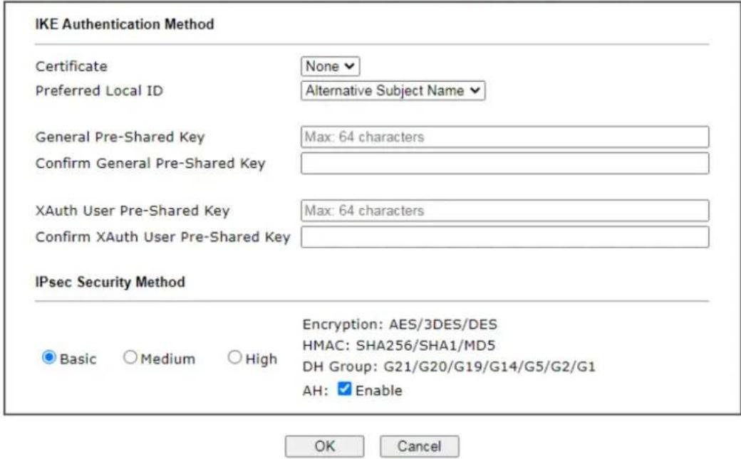
text_image
IKE Authentication Method Certificate None Preferred Local ID Alternative Subject Name General Pre-Shared Key Max: 64 characters Confirm General Pre-Shared Key XAuth User Pre-Shared Key Max: 64 characters Confirm XAuth User Pre-Shared Key IPsec Security Method Basic Medium High Encryption: AES/3DES/DES HMAC: SHA256/SHA1/MD5 DH Group: G21/G20/G19/G14/G5/G2/G1 AH: Enable OK CancelAvailable settings are explained as follows:
| Item | Description |
| IKE Authentication Method | This usually applies to those are remote dial-in user or node (LAN-to-LAN) which uses dynamic IP address and IPsec-related VPN connections such as L2TP over IPsec and IPsec tunnel. There are two methods offered by Vigor router for you to authenticate the incoming data coming from remote dial-in user, Certificate (X.509) and Pre-Shared Key.Certificate - X.509 certificates can be used for IKE authentication. To set up certificates on the router, go to the Certificate Management section.Preferred Local ID - Specify the preferred local ID information (Alternative Subject Name First or Subject Name First) for IPsec authentication while the client is using the general setting (without a specific Peer IP or ID in the VPN profile).General Pre-Shared Key- Define the PSK key for general authentication.Confirm General Pre-Shared Key- Re-enter the characters to confirm the pre-shared key.XAuth User Pre-Shared Key - Define the PSK key for IPsec XAuth authentication.Confirm XAuth User Pre-Shared Key- Re-enter the characters to confirm the pre-shared key for IPsec XAuth authentication.Note: Any packets from the remote dial-in user which does not match the rule defined in VPN and Remote Access>>Remote Dial-In User will be applied with the method specified here. |
| IPsec Security Method | Available methods include Basic, Medium and High. Each method offers different encryption, HMAC and DH Group.Basic - Authentication Header (AH) means data will be authenticated, but not be encrypted. By default, this option is active.Medium - When this option is selected, the Authentication Header (AH) protocol can be used to provide authentication to IPsec traffic.High - When this option is selected, the Encapsulating Security Payload (ESP) protocol can be used to provide authentication and encryption to IPsec traffic. Three encryption standards are supported for ESP: DES, 3DES and AES, in ascending order of security. |
After finishing all the settings here, please click OK to save the configuration.
IV-1-6 IPsec Peer Identity
To use digital certificate for peer authentication in either LAN-to-LAN connection or Remote User Dial-In connection, here you may edit a table of peer certificate for selection. As shown below, the router provides 32 entries of digital certificates for peer dial-in users.
VPN and Remote Access >> IPsec Peer Identity
| X509 Peer ID Accounts: | | Set to Factory Default | | ||||
| Index | Enable | Name | Index | Enable | Name |
| 1. | □ | ??? | 17. | □ | ??? |
| 2. | □ | ??? | 18. | □ | ??? |
| 3. | □ | ??? | 19. | □ | ??? |
| 4. | □ | ??? | 20. | □ | ??? |
| 5. | □ | ??? | 21. | □ | ??? |
| 6. | □ | ??? | 22. | □ | ??? |
| 7. | □ | ??? | 23. | □ | ??? |
| 8. | □ | ??? | 24. | □ | ??? |
| 9. | □ | ??? | 25. | □ | ??? |
| 10. | □ | ??? | 26. | □ | ??? |
| 11. | □ | ??? | 27. | □ | ??? |
| 12. | □ | ??? | 28. | □ | ??? |
| 13. | □ | ??? | 29. | □ | ??? |
| 14. | □ | ??? | 30. | □ | ??? |
| 15. | □ | ??? | 31. | □ | ??? |
| 16. | □ | ??? | 32. | □ | ??? |

Available settings are explained as follows:
| Item | Description |
| Set to Factory Default Click it to clear all indexes. | |
| Index Click the number below Index to access into the setting page of IPsec Peer Identity. | |
| Name Display the profile name of that index. | |
Click each index to edit one peer digital certificate. There are three security levels of digital signature authentication: Fill each necessary field to authenticate the remote peer. The following explanation will guide you to fill all the necessary fields.
Profile Index : 1
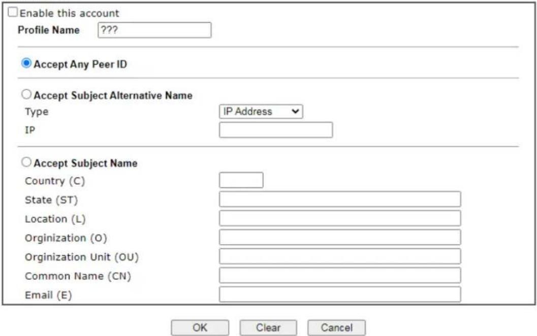
text_image
Enable this account Profile Name ???? Accept Any Peer ID Accept Subject Alternative Name Type IP Address IP Accept Subject Name Country (C) State (ST) Location (L) Organization (O) Organization Unit (OU) Common Name (CN) Email (E) OK Clear CancelAvailable settings are explained as follows:
| Item | Description |
| Profile Name Enter the name of the profile. The maximum length of the name you can set is 32 characters. | |
| Enable this account Check it to enable such account profile. | |
| Accept Any Peer ID Click to accept any peer regardless of its identity. | |
| Accept Subject Alternative Name | Click to check one specific field of digital signature to accept the peer with matching value. The field can be IP Address, Domain, or E-mail. The box under the Type will appear according to the type you select and ask you to fill in corresponding setting. |
| Accept Subject Name | Click to check the specific fields of digital signature to accept the peer with matching value. The field includes Country (C), State (ST), Location (L), Organization (O), Organization Unit (OU), Common Name (CN), and Email (E). |
After finishing all the settings here, please click OK to save the configuration.
IV-1-7 VPN Matcher Setup
Normally, to establish VPN connection, at least one peer must have a public IP address. The VPN Matcher server can help two Draytek routers behind NAT establish a secure VPN tunnel for data transmission between each other. Refer to the following figure.

flowchart
graph TD
    A["Internet"] --> B["NAT"]
    A --> C["NAT"]
    B --> D["LAN: 192.168.1.1"]
    C --> E["LAN: 192.168.2.1"]
    F["VPN Matcher Server"] --> A
    G["VPN Tunnel"] --> A
    H["WAN: 100.64.200.1"] --> B
    I["WAN: 100.64.200.5"] --> C
There is one limitation for the VPN connection. Both routers must be behind a cone NAT, but not symmetric NAT.
Go to VPN and Remote Access>>VPN Matcher Setup to open the following page.
VPN and Remote Access >> VPN Matcher Setup
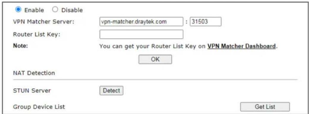
text_image
Enable Disable VPN Matcher Server: vpn-matcher.draytek.com : 31503 Router List Key: Note: You can get your Router List Key on VPN Matcher Dashboard. OK NAT Detection STUN Server Detect Group Device List Get ListAvailable settings are explained as follows:
| Item | Description |
| Enable / Disable | Click to enable / disable the function of VPN Matcher Setup. |
| VPN Matcher Server The IP | address of the DrayTek VPN Matcher server is defined as "vpn-matcher.draytek.com" with the port nubmer "31503". |
| Router List Key | Enter the authentication key for finding a Vigor router with the same group of this device from the VPN matcher server. Then set a VPN link between Vigor routers on both ends viaVPN wizard. |
| OK Click to save the settings. | |
| STUN Server | Detect - Click to check if the NAT used by Vigor router is core NAT or not. If not, no VPN can be established. |
| Group Device List Get List | After entering the Authkey above, click to get available Vigor router which is within the same group as this device. |
IV-1-8 OpenVPN
The OpenVPN protocol utilizes public keys, certificates, and usernames and passwords to authenticate the client. Traffic is carried over secure channels built upon industry-standard SSL/ TLS encryption protocols.
With integrating of OpenVPN, Vigor router can help users to achieve more robust, reliable and secure private connections for business needs.
OpenVPN offers a convenient way for users to build a VPN between the local end and the remote end. There are two advantages of OpenVPN:
- It can be operated on different systems such as Windows, Linux, and MacOS.
- Based on the standard protocol of SSL encryption, OpenVPN can provide you with a scalable client/server mode, permitting multi-client to connect to a single OpenVPN Server process over a single TCP or UDP port.
In terms of credentials, the administrator can choose to let the router generate the certificates, or import certificates issued by third-party certificate authorities (CAs). When the router generates the certificates, it acts as the root CA to issue the trusted CA certificates (stored under Certificate Management >> Trusted CA Certificate), which are used to generate the server and client certificates used by OpenVPN (stored under Certificate Management >> Local Certificate). If, however, a certificate issued by a third-party CA is used, both the CA's certificate and the issued certificate need to be imported to the router in the Trusted CA Certificate and Local Certificate sections, respectively.
IV-1-8-1 Open VPN Server Setup
OpenVPN requires the use of certificates. Before establishing OpenVPN connection, general settings for OpenVPN service shall be configured first.
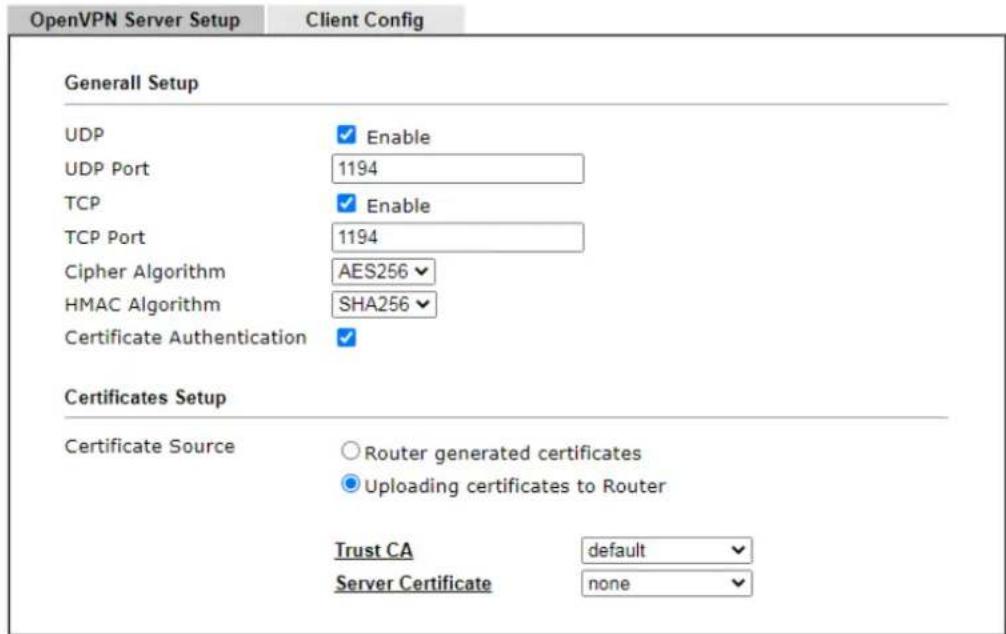
text_image
OpenVPN Server Setup Client Config General Setup UDP UDP Port TCP TCP Port Cipher Algorithm HMAC Algorithm Certificate Authentication Enable Enable AES256 SHA256 Certificates Setup Certificate Source Router generated certificates Uploading certificates to Router Trust CA default Server Certificate noneNote: OpenVPN on vigor only support TUN device interface currently. So please setup corresponding configurations on the client side.
OK
Available settings are explained as follows:
| Item | Description |
| General Setup | |
| UDP | Enable - Select checkboxOpenVPN connections.UDP Port - Enter the UDP port number. |
| TCP | Enable - Select checkboxOpenVPN connections.TCP Port - Enter the TCP port number. |
| Cipher Algorithm Select the desired cipher algorithm. Two encryption algorithms are supported: AES128 and AES256. AES256 is more secure than AES128 but may result in lower performance because it incurs higher computational overhead. | |
| HMAC Algorithm HMAC stands for Hash-based Message Authentication Code. It is used to validate the data integrity and authenticity of the VPN data.Select the desired HMAC hash algorithm. Two hash algorithms, SHA1 and SHA256, are supported. SHA256 is preferred as it is more robust and reliable than SHA1. | |
| Certificate Authentication | Select this checkbox if you would like to validate that the client certificate was issued by a trusted CA. |
| Certificate Setup | |
| Certificate Source Select a source for the certificate to be used for OpenVPN.Router generated certificates - Router-generated | |
| certificates that will be used for OpenVPN.GENERATE- Click to generate a certificate.Delete all certificate- Click to remove all certificates generated by the router. Uploading certificates to Router- Third-party certificates will be used for OpenVPN.Trust CA- Use the dropdown list to select a trusted CA certificate that has already been uploaded to the router. To upload Trusted CA certificates to the router, click the Trust CA label and you will be taken to the Certificate Management >> Trusted CA Certificate page to perform the operation.Server Certificate- Use the dropdown list to select a server certificate that has already been uploaded to the router. To upload server certificates to the router, click the Server Certificate label and you will be taken to the Certificate Management >> Local Certificate page to perform the operation. |
After finishing all the settings here, please click OK to save the configuration.
IV-1-8-2 Client Config
On this page, you can create and export the configuration required for a remote OpenVPN client to connect to the router.
VPN and Remote Access >> OpenVPN

OpenVPN Server Setup
Client Config
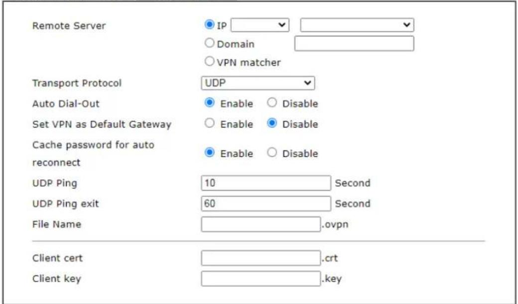
text_image
Remote Server IP Domain VPN matcher Transport Protocol UDP Auto Dial-Out Enable Disable Set VPN as Default Gateway Enable Disable Cache password for auto reconnect Enable Disable UDP Ping 10 Second UDP Ping exit 60 Second File Name .ovpn Client cert .crt Client key .keyNote:
- Please make sure the Client cert and the Client key are located in the same folder with .ovpn file.
- Please make sure that WAN can be used as OpenVPN server.
- Cache password for auto reconnect. Enabled: Cache password in virtual memory for re-authentication to keep VPN always connected. Disabled: Type password manually when re-authentication needed. VPN may disconnect during re-authentication.
Export
Available settings are explained as follows:
| Item | Description |
| Remote Server The OpenVPN | N client will use the IP address or domain name to connect to the router. Select either IP or Domain.IP - The OpenVPN configuration file will use the numeric IP address as the server address.Domain - The OpenVPN configuration file will use the domain as the server address. You need to ensure that the domain resolves to the IP address of a router WAN port.VPN matcher - The OpenVPN configuration file will use the VPN matcher as the server address. |
| Transport Protocol Select UDP or TCP for the protocol to be used by the OpenVPN client to connect to the router. | |
| Auto Dial-Out Enable - If selected, the remote client can auto-dial to this Vigor router to build an OpenVPN tunnel.Disable - Select to disable the function. | |
| Set VPN as Default Enable - | If selected, the Vigor router will be treated as a |
| Gateway "default" gateway | for OpenVPN clients. The OpenVPN client will redirect all the traffic to the Vigor router via the OpenVPN tunnel.Disable - Select to disable the function. |
| Cache password for auto reconnect | Enable - The default setting. Save the config information with the password required for the OpenVPN tunnel connection.Disable - Save the config information without the password information. If it is selected, the user must re-enter the password for authentication while setting the network connection via OpenVPN tunnel. |
| UDP Ping | Ping remote device over the UDP control channel, if no packets have been sent for the number of seconds configured here. |
| UDP Ping exit Let OpenVPN | exit after the seconds set here if no reception of a ping or other packet from the remote device. |
| File Name Enter the filename | of the configuration file to be downloaded from the router. |
| CA cert Enter the certificate | authority (CA) file name obtained from 3rd party provider. |
| Client cert Enter the filename | of the client certificate obtained from 3rd party provider. |
| Client key Enter the filename | of the private key obtained from the 3rd party provider. |
| Export | Click this button to download the settings on this page as a file, which can be imported into a VPN client to establish OpenVPN connections. |
IV-1-9 Remote Dial-in User
You can manage remote access by maintaining a table of remote user profile, so that users can be authenticated to dial-in via VPN connection. You may set parameters including specified connection peer ID, connection type (VPN connection - including PPTP, IPsec Tunnel, and L2TP by itself or over IPsec) and corresponding security methods, etc.
The router provides multiple access accounts for dial-in users. Besides, you can extend the user accounts to the RADIUS server through the built-in RADIUS client function. The following figure shows the summary table.
VPN and Remote Access >> Remote Dial-in User

Remote Access User Accounts:
Set to Factory Default
| Index | Enable | User | Status | Index | Enable | User | Status |
| 1. | ??? | --- | 17. | ??? | --- | ||
| 2. | ??? | --- | 18. | ??? | --- | ||
| 3. | ??? | --- | 19. | ??? | --- | ||
| 4. | ??? | --- | 20. | ??? | --- | ||
| 5. | ??? | --- | 21. | ??? | --- | ||
| 6. | ??? | --- | 22. | ??? | --- | ||
| 7. | ??? | --- | 23. | ??? | --- | ||
| 8. | ??? | --- | 24. | ??? | --- | ||
| 9. | ??? | --- | 25. | ??? | --- | ||
| 10. | ??? | --- | 26. | ??? | --- | ||
| 11. | ??? | --- | 27. | ??? | --- | ||
| 12. | ??? | --- | 28. | ??? | --- | ||
| 13. | ??? | --- | 29. | ??? | --- | ||
| 14. | ??? | --- | 30. | ??? | --- | ||
| 15. | ??? | --- | 31. | ??? | --- | ||
| 16. | ??? | --- | 32. | ??? | --- |

Available settings are explained as follows:
| Item | Description |
| Set to Factory Default Click | to clear all indexes. |
| Index Click the number below | Index to access into the setting page of Remote Dial-in User. |
| Enable Check the box to enable the profile. | |
| User | Display the username for the specific dial-in user of the LAN-to-LAN profile. The symbol ??? represents that the profile is empty. |
| Status Display the access state of the specific dial-in user. The symbol V and X represent the specific dial-in user to be active and inactive, respectively. | |
Click each index to edit one remote user profile. Each Dial-In Type requires you to fill the different corresponding fields on the right. If the fields gray out, it means you may leave it untouched. The following explanation will guide you to fill all the necessary fields.
VPN and Remote Access >> Remote Dial-in User
Index No. 1
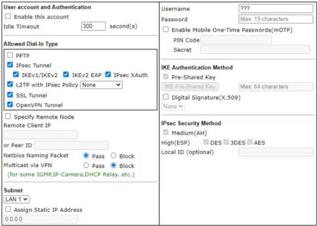
text_image
User account and Authentication Enable this account Idle Timeout 300 second(s) Allowed Dial-In Type PPTP IPsec Tunnel IKEv1/IKEv2 IKEv2 EAP IPsec XAuth L2TP with IPsec Policy None SSL Tunnel OpenVPN Tunnel Specify Remote Node Remote Client IP or Peer ID Netbios Naming Packet Pass Block Multicast via VPN Pass Block (for some IGMP,IP-Camera,DHCP Relay..etc.) Subnet LAN 1 Assign Static IP Address 0.0.0.0 Username ???? Password Max: 19 characters Enable Mobile One-Time Passwords(mOTP) PIN Code: Secret IKE Authentication Method Pre-Shared Key IKE Pre-Shared Key Max: 64 characters Digital Signature(X.509) None IPsec Security Method Medium(AH) High(ESP) DES 3DES AES Local ID (optional)Note:
- Username can not contain characters ' \ " and \ ».
- OpenVPN tunnel does not support mOTP.
- When your are trying to use OpenVPN tunnel and the router is behind NAT, you may have to enable the VPN-Matcher feature to bypass the NAT.
- VPN-Matcher can only be used behind Cone NAT.

Available settings are explained as follows:
| Item | Description |
| User account and Authentication | Enable this account - Check the box to enable this function.Idle Timeout- If the dial-in user is idle over the limitation of the timer, the router will drop this connection. By default, the Idle Timeout is set to 300 seconds. |
| Allowed Dial-In Type | PPTP - Allow the remote dial-in user to make a PPTP VPN connection through the Internet. You should set the User Name and Password of remote dial-in user below.IPsec Tunnel - Allow the remote dial-in user to make an IPsec VPN connection through Internet.L2TP with IPsec Policy - Allow the remote dial-in user to make a L2TP VPN connection through the Internet. You can select to use L2TP alone or with IPsec. Select from below:● None - Do not apply the IPsec policy. Accordingly, the VPN connection employed the L2TP without IPsec policy can be viewed as one pure L2TP connection.● Nice to Have - Apply the IPsec policy first, if it is applicable during negotiation. Otherwise, the dial-in VPN connection becomes one pure L2TP connection.● Must -Specify the IPsec policy to be definitely applied on the L2TP connection.SSL Tunnel - Allow the remote dial-in user to make an SSL VPN connection through Internet.Specify Remote Node -You can specify the IP address of the remote dial-in user, ISDN number or peer ID (used in IKE aggressive mode).Uncheck the checkbox means the connection type you select above will apply the authentication methods and security methods in the general settings.Netbios Naming Packet -● Pass - Click it to have an inquiry for data transmission between the hosts located on both sides of VPN Tunnel while connecting.● Block - When there is conflict occurred between the hosts on both sides of VPN Tunnel in connecting, such function can block data transmission of Netbios Naming Packet inside the tunnel.Multicast via VPN - Some programs might send multicast packets via VPN connection.● Pass - Click this button to let multicast packets pass through the router.● Block - This is default setting. Click this button to let multicast packets be blocked by the router.User Name - This field is applicable when you select PPTP or L2TP with or without IPsec policy above. The length of the name is limited to 23 characters.Password - This field is applicable when you select PPTP or L2TP with or without IPsec policy above. The length of the password is limited to 19 characters.Enable Mobile One-Time Passwords (mOTP) - Check this box to make the authentication with mOTP function.PIN Code - Enter the code for authentication (e.g, 1234).Secret - Use the 32 digit-secret number generated by mOTP in the mobile phone (e.g., e759bb6f0e94c7ab4fe6). |
| Subnet | Chose one of the subnet selections for such VPN profile.Assign Static IP Address - Please type a static IP address for the subnet you specified. |
| IKE Authentication Method | This group of fields is applicable for IPsec Tunnels and L2TP with IPsec Policy when you specify the IP address of the remote node. The only exception is Digital Signature (X.509) can be set when you select IPsec tunnel either with or without specifying the IP address of the remote node.Pre-Shared Key - Check the box of Pre-Shared Key to invoke this function and Enter the required characters (1-63) as the pre-shared key.Digital Signature (X.509) - Check the box of Digital Signature to invoke this function and Select one predefined Profiles set in the VPN and Remote Access >>IPsec Peer Identity. |
| IPsec Security Method | This group of fields is a must for IPsec Tunnels and L2TP withIPsec Policy when you specify the remote node. Check the Medium, DES, 3DES or AES box as the security method.Medium-Authentication Header (AH) means data will be authenticated, but not be encrypted. By default, this option is invoked. You can uncheck it to disable it.High-Encapsulating Security Payload (ESP) means payload (data) will be encrypted and authenticated. You may select encryption algorithm from Data Encryption Standard (DES), Triple DES (3DES), and AES.Local ID (Optional)- Specify a local ID to be used for Dial-in setting in the LAN-to-LAN Profile setup. This item is optional and can be used only in IKE aggressive mode. |
After finishing all the settings here, please click OK to save the configuration.
IV-1-10 LAN to LAN
Here you can manage LAN-to-LAN connections by maintaining a table of connection profiles. You may set parameters including specified connection direction (dial-in or dial-out), connection peer ID, connection type (VPN connection - including PPTP, IPsec Tunnel, and L2TP by itself or over IPsec) and corresponding security methods, etc.
VPN and Remote Access >> LAN to LAN

LAN-to-LAN Profiles:
Set to Factory Default
| Index | Enable | Name | Remote Network | Status | Index | Enable | Name | Remote Network | Status |
| 1. | ??? | --- | 17. | ??? | --- | ||||
| 2. | ??? | --- | 18. | ??? | --- | ||||
| 3. | ??? | --- | 19. | ??? | --- | ||||
| 4. | ??? | --- | 20. | ??? | --- | ||||
| 5. | ??? | --- | 21. | ??? | --- | ||||
| 6. | ??? | --- | 22. | ??? | --- | ||||
| 7. | ??? | --- | 23. | ??? | --- | ||||
| 8. | ??? | --- | 24. | ??? | --- | ||||
| 9. | ??? | --- | 25. | ??? | --- | ||||
| 10. | ??? | --- | 26. | ??? | --- | ||||
| 11. | ??? | --- | 27. | ??? | --- | ||||
| 12. | ??? | --- | 28. | ??? | --- | ||||
| 13. | ??? | --- | 29. | ??? | --- | ||||
| 14. | ??? | --- | 30. | ??? | --- | ||||
| 15. | ??? | --- | 31. | ??? | --- | ||||
| 16. | ??? | --- | 32. | ??? | --- |


text_image
Pass packets from LAN in Routing mode to VPN ✓ Pass Packets to WAN when VPN disconnectsAvailable settings are explained as follows:
| Item | Description |
| Set to Factory Default Click | to clear all indexes. |
| Index Click the number link | to access into the setting page of a VPN profile. |
| Enable Check it to enable such LAN to LAN profile. | |
| Name | Indicate the name of the LAN-to-LAN profile. The symbol ??? represents that the profile is empty. |
| Remote Network Display the | IP address with the netmask of remote network. |
| Status Online - means such | LAN to LAN profile is in use.Offline - means such LAN to LAN profile isn't in use even if the profile has been enabled. |
To edit each profile:
- Click each index to edit each profile and you will get the following page. Each LAN-to-LAN profile includes 4 subgroups. If the fields gray out, it means you may leave it untouched. The following explanations will guide you to fill all the necessary fields.
VPN and Remote Access >> LAN to LAN
Profile Index : 1
- Common Settings
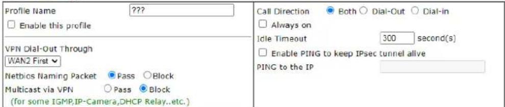
text_image
Profile Name Enable this profile VPN Dial-Out Through WAN2 First Netbios Naming Packet Pass Block Multicast via VPN Pass Block (for some IGMP,IP-Camera,DHCP Relay..etc.) Call Direction Both Dial-Out Dial-in Always on Idle Timeout 300 second(s) Enable PING to keep IPsec tunnel alive PING to the IP- Dial-Out Settings
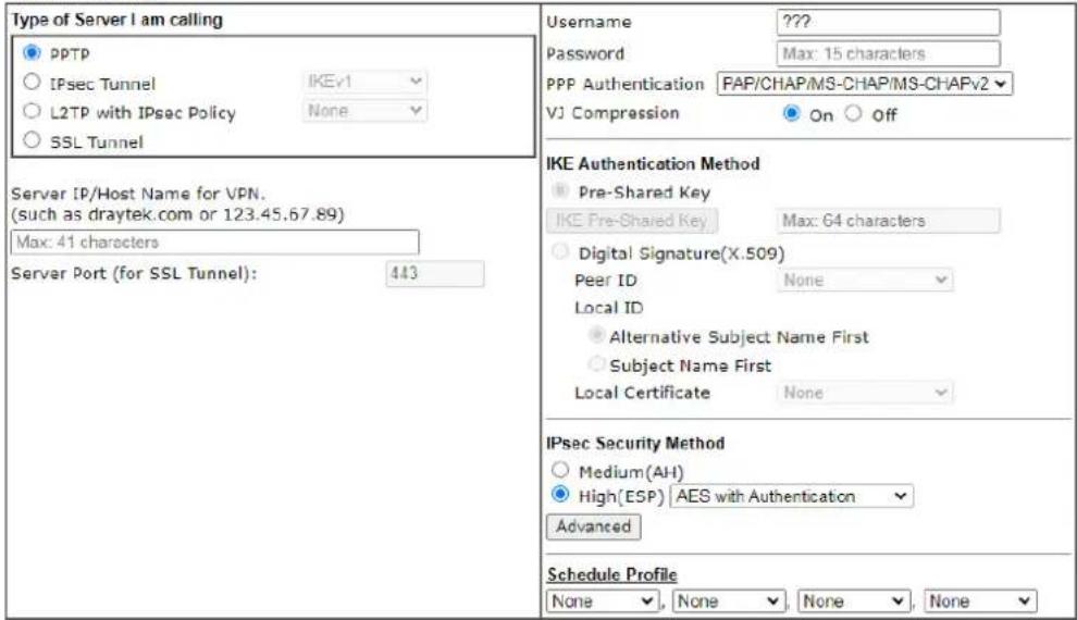
text_image
Type of Server I am calling ● pPTP ○ IPsec Tunnel IKEv1 ○ L2TP with IPsec Policy None ○ SSL Tunnel Server IP/Host Name for VPN. (such as draytek.com or 123.45.67.89) Max: 41 characters Server Port (for SSL Tunnel): 443 Username ???? Password Max: 15 characters PPP Authentication FAP/CHAP/MS-CHAP/MS-CHAPv2 VJ Compression On Off IKE Authentication Method ● Pra-Shared Key Max: 64 characters IKE Pre-Shared Key ○ Digital Signature(X.509) Peer ID None Local ID ● Alternative Subject Name First ○ Subject Name First Local Certificate None IPsec Security Method ○ Medium(AH) ● High(ESP) AES with Authentication Advanced Schedule Profile None None None NoneAvailable settings are explained as follows:
| Item | Description |
| Common Settings Profile | Name - Specify a name for the profile of the LAN-to-LAN connection. |
Enable this profile - Check here to activate this profile.
VPN Dial-Out Through - Use the drop down menu to choose a proper WAN interface for this profile. This setting is useful for dial-out only.
- WAN2 First/ LTE First - While connecting, the router will use WAN2 or LTE as the first channel for VPN connection. If WAN2 or LTE fails, the router will use another WAN interface instead.
- WAN2 Only/ LTE Only - While connecting, the router will use WAN2 or LTE as the only channel for VPN connection.
Netbios Naming Packet
- Pass - click it to have an inquiry for data transmission between the hosts located on both sides of VPN Tunnel while connecting.
- Block – When there is conflict occurred between the hosts on both sides of VPN Tunnel in connecting, such function can block data transmission of Netbios Naming Packet inside the tunnel.
Multicast via VPN - Some programs might send multicast packets via VPN connection.
- Pass - Click this button to let multicast packets pass through the router.
- Block - This is default setting. Click this button to let multicast packets be blocked by the router.
Call Direction - Specify the allowed call direction of this LAN-to-LAN profile.
● Both:-initiator/responder
- Dial-Out- initiator only
- Dial-In- responder only.
Always On-Check to enable router always keep VPN connection.
Idle Timeout: The default value is 300 seconds. If the connection has been idled over the value, the router will drop the connection.
Enable PING to keep IPsec tunnel alive - This function is to help the router to determine the status of IPsec VPN connection, especially useful in the case of abnormal VPN IPsec tunnel disruption. For details, please refer to the note below. Check to enable the transmission of PING packets to a specified IP address.
This function is used to handle abnormal IPsec VPN connection disruption. It will help to provide the state of a VPN connection for router's judgment of redial. Normally, if any one of VPN peers wants to disconnect the connection, it should follow a serial of packet exchange procedure to inform each other. However, if the remote peer disconnects without notice, Vigor router will by no where to know this situation. To resolve this dilemma, by continuously sending PING packets to the remote host, the Vigor router can know the true existence of this VPN connection and react accordingly. This is independent of DPD (dead peer detection).
PING to the IP - Enter the IP address of the remote host that located at the other-end of the VPN tunnel.
| Dial-Out Settings Type | of Server I am calling - PPTP - Build a PPTP VPN connection to the server through the Internet. You should set the identity like User Name and Password below for the authentication of remote server.IPsec Tunnel - Build an IPsec VPN connection to the server through Internet.L2TP with IPsec Policy - Build a L2TP VPN connection through the Internet. You can select to use L2TP alone or with IPsec. Select from below:None: Do not apply the IPsec policy. Accordingly, the VPN connection employed the L2TP without IPsec policy can be viewed as one pure L2TP connection.Nice to Have: Apply the IPsec policy first, if it is applicable during negotiation. Otherwise, the dial-out VPN connection becomes one pure L2TP connection.Must: Specify the IPsec policy to be definitely applied on the L2TP connection.SSL Tunnel - Build an SSL VPN connection to the server through Internet.User Name - This field is applicable when you select, PPTP or L2TP with or without IPsec policy above. The length of the name is limited to 49 characters.Password - This field is applicable when you select PPTP or L2TP with or without IPsec policy above. The length of the password is limited to 15 characters.PPP Authentication - This field is applicable when you select, PPTP or L2TP with or without IPSec policy above. PAP/ CHAP/ MS-CHAP/ MS-CHAPv2 is the most common selection due to compatibility.VJ compression - This field is applicable when you select PPTP or L2TP with or without IPsec policy above. VJ Compression is used for TCP/ IP protocol header compression. Normally set to On to improve bandwidth utilization.IKE Authentication Method - This group of fields is applicable for IPsec Tunnels and L2TP with IPsec Policy.Pre-Shared Key - Input 1-63 characters as pre-shared key.Digital Signature (X.509) - Select one predefined Profiles set in the VPN and Remote Access >>IPsec Peer Identity.Peer ID - Select one of the predefined Profiles set in VPN and Remote Access >>IPsec Peer Identity.Local ID - Specify a local ID (Alternative Subject Name First or Subject Name First) to be used for Dial-in setting in the LAN-to-LAN Profile setup. This item is optional and can be used only in IKE aggressive mode.Local Certificate - Select one of the profiles set in Certificate Management>>Local Certificate.IPsec Security Method - This group of fields is a must for IPsec Tunnels and L2TP with IPsec Policy.M edium AH (Authentication Header) means data will be authenticated, but not be encrypted. By default, this option is active.High (ESP-Encapsulating Security Payload)- means payload (data) will be encrypted and authenticated. |
Select from below:
■ DES without Authentication -Use DES encryption algorithm and not apply any authentication scheme.
■ DES with Authentication-Use DES encryption algorithm and apply MD5 or SHA-1 authentication algorithm.
■ 3DES without Authentication-Use triple DES encryption algorithm and not apply any authentication scheme.
■ 3DES with Authentication-Use triple DES encryption algorithm and apply MD5 or SHA-1 authentication algorithm.
■ AES without Authentication-Use AES encryption algorithm and not apply any authentication scheme.
■ AES with Authentication-Use AES encryption algorithm and apply MD5 or SHA-1 authentication algorithm.
Advanced - Specify mode, proposal and key life of each IKE phase, Gateway, etc.
The window of advance setup is shown as below:
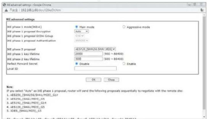
text_image
IKE advanced settings - Google Chrome 不安全 | 192.168.1.60/doc/IDkeDr.htm IKE advanced settings IKE phase 1 mode(IKEv1) IKE phase 1 proposal Encryption IKE phase 1 proposal ECDH Group IKE phase 1 proposal Authentication IKE phase 2 proposal IKE phase 1 key lifetime IKE phase 2 key lifetimes Perfect Forward Secret Local ID Main mode Auto G14 SHA256 AES126_(SHA256,SHA1,MD5) 28000 (900 ~ 86400) 1600 (600 ~ 86400) Disable Enable OK Close Note: If you select "Auto" as IKE phase 1 proposal, router will send the following proposals sequentially to negotiate with the remote site: 1. AES256_(SHA256/SHA1/MD5)_G14 2. AES256_(SHA1/MD5)_G5 3. AES192_(SHA1/MD5)_G14 4. AES126_(SHA1/MD5)_G5 5. IDE5_(SHA1/MD5)_G5IKE phase 1 mode -Select from Main mode and Aggressive mode. The ultimate outcome is to exchange security proposals to create a protected secure channel. Main mode is more secure than Aggressive mode since more exchanges are done in a secure channel to set up the IPsec session. However, the Aggressive mode is faster. The default value in Vigor router is Main mode.
- IKE phase 1 proposal-To propose the local available authentication schemes and encryption algorithms to the VPN peers, and get its feedback to find a match. Two combinations are available for Aggressive mode and nine for Main mode. We suggest you select the combination that covers the most schemes.
- IKE phase 2 proposal-To propose the local available algorithms to the VPN peers, and get its feedback to find a match. Three combinations are available for both modes. We suggest you select the combination that covers the most algorithms.
- IKE phase 1 key lifetime-For security reason, the lifetime of key should be defined. The default value is 28800 seconds. You may specify a value in between 900 and 86400 seconds.
- IKE phase 2 key lifetime-For security reason, the lifetime of key should be defined. The default value is 3600 seconds. You may specify a value in between 600 and 86400 seconds.
● Perfect Forward Secret (PFS)-The IKE Phase 1 key will be reused to avoid the computation complexity in phase 2. The default value is inactive this function.
Local ID-In Aggressive mode, Local ID is on behalf of the IP address while identity authenticating with remote VPN server. The length of the ID is limited to 47 characters.
Schedule Profile - Set the wireless LAN to work at certain time interval only. You may choose up to 4 schedules out of the 15 schedules pre-defined in Applications >> Schedule setup. The default setting of this field is blank and the function will always work.
3. Dial-In Settings
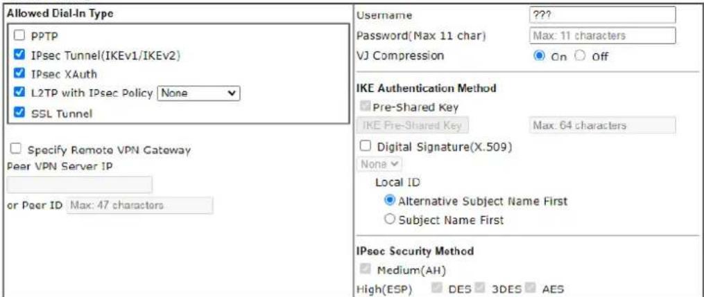
text_image
Allowed Dial-In Type □ PPTP ✓ IPsec Tunnel(IKEv1/IKEv2) ✓ IPsec XAuth ✓ L2TP with IPsec Policy None ✓ SSL Tunnel □ Specify Remote VPN Gateway Peer VPN Server IP or Peer ID Max: 47 characters Username ???? Password(Max 11 char) Max: 11 characters VJ Compression On Off IKE Authentication Method ■ Pre-Shared Key IKE Pre-Shared Key Max: 64 characters □ Digital Signature(X.509) None Local ID ● Alternative Subject Name First ○ Subject Name First IPsec Security Method ■ Medium(AH) High(ESP) DES 3DES AES4. TCP/IP Network Settings
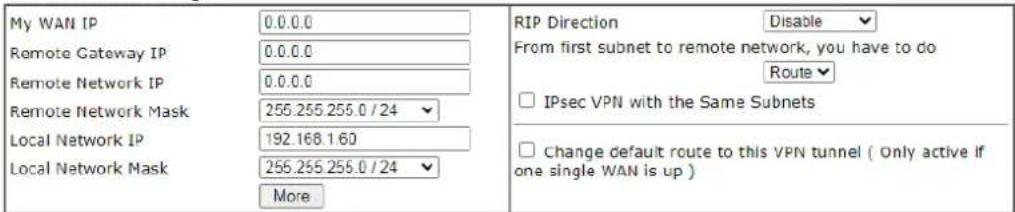
text_image
My WAN IP 0.0.0.0 Remote Gateway IP 0.0.0.0 Remote Network IP 0.0.0.0 Remote Network Mask 255.255.255.0 / 24 Local Network IP 192.168.1.60 Local Network Mask 255.255.255.0 / 24 More RIP Direction Disable From first subnet to remote network, you have to do Route □ IPsec VPN with the Same Subnets □ Change default route to this VPN tunnel ( Only active if one single WAN is up )
Available settings are explained as follows:
| Item | Description |
| Dial-In Settings Allowed | Dial-In Type - Determine the dial-in connection with different types.PPTP - Allow the remote dial-in user to make a PPTP VPN connection through the Internet. You should set the User Name and Password of remote dial-in user below.IPsec Tunnel- Allow the remote dial-in user to trigger an IPsec VPN connection through Internet.L2TP with IPsec Policy - Allow the remote dial-in user to make a L2TP VPN connection through the Internet. You can select to use L2TP alone or with IPsec. Select from below: |
■ None - Do not apply the IPsec policy. Accordingly, the VPN connection employed the L2TP without IPsec policy can be viewed as one pure L2TP connection.
- Nice to Have - Apply the IPsec policy first, if it is applicable during negotiation. Otherwise, the dial-in VPN connection becomes one pure L2TP connection.
■ Must - Specify the IPsec policy to be definitely applied on the L2TP connection.
- SSL Tunnel- Allow the remote dial-in user to trigger an SSL VPN connection through Internet.
Specify Remote VPN Gateway - You can specify the IP address of the remote dial-in user or peer ID (should be the same with the ID setting in dial-in type) by checking the box. Also, you should further specify the corresponding security methods on the right side.
If you uncheck the checkbox, the connection type you select above will apply the authentication methods and security methods in the general settings.
Username - This field is applicable when you select PPTP or L2TP with or without IPsec policy above. The length of the name is limited to 11 characters.
Password - This field is applicable when you select PPTP or L2TP with or without IPsec policy above. The length of the password is limited to 11 characters.
VJ Compression - VJ Compression is used for TCP/IP protocol header compression. This field is applicable when you select PPTP or L2TP with or without IPsec policy above.
IKE Authentication Method - This group of fields is applicable for IPsec Tunnels and L2TP with IPsec Policy when you specify the IP address of the remote node. The only exception is Digital Signature (X.509) can be set when you select IPsec tunnel either with or without specify the IP address of the remote node.
- Pre-Shared Key - Check the box of Pre-Shared Key to invoke this function and Enter the required characters (1-63) as the pre-shared key.
- Digital Signature (X.509) -Check the box of Digital Signature to invoke this function and select one predefined Profiles set in the VPN and Remote Access >>IPsec Peer Identity.
■ Local ID – Specify which one will be inspected first.
■ Alternative Subject Name First – The alternative subject name (configured in Certificate Management>>Local Certificate) will be inspected first.
■ Subject Name First – The subject name (configured in Certificate Management>>Local Certificate) will be inspected first.
IPsec Security Method - This group of fields is a must for IPsec Tunnels and L2TP with IPsec Policy when you specify the remote node.
● Medium- Authentication Header (AH) means data will be authenticated, but not be encrypted. By default,
| this option is active.●High- Encapsulating Security Payload (ESP) means payload (data) will be encrypted and authenticated.You may select encryption algorithm from Data Encryption Standard (DES), Triple DES (3DES), and AES. | |
| TCP/IP Network Settings | My WAN IP -This field is only applicable when you select PPTP or L2TP with or without IPsec policy above. The default value is 0.0.0.0, which means the Vigor router will get a PPP IP address from the remote router during the IPCP negotiation phase. If the PPP IP address is fixed by remote side, specify the fixed IP address here. Do not change the default value if you do not select PPTP or L2TP.Remote Gateway IP - This field is only applicable when you select PPTP or L2TP with or without IPsec policy above. The default value is 0.0.0.0, which means the Vigor router will get a remote Gateway PPP IP address from the remote router during the IPCP negotiation phase. If the PPP IP address is fixed by remote side, specify the fixed IP address here. Do not change the default value if you do not select PPTP or L2TP.Remote Network IP/ Remote Network Mask - Add a static route to direct all traffic destined to this Remote Network IP Address/ Remote Network Mask through the VPN connection. For IPsec, this is the destination clients IDs of phase 2 quick mode.Local Network IP / Local Network Mask - Display the local network IP and mask for TCP / IP configuration. You can modify the settings if required.More - Add a static route to direct all traffic destined to more Remote Network IP Addresses/ Remote Network Masks through the VPN connection. This is usually used when you find there are several subnets behind the remote VPN router.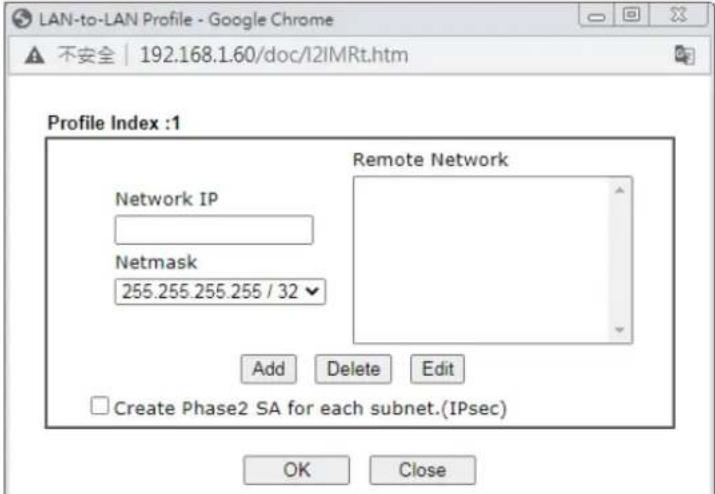 RIP Direction - The option specifies the direction of RIP (Routing Information Protocol) packets. You can enable/ disable one of direction here. Herein, we provide four options: TX/ RX Both, TX Only, RX Only, and Disable.From first subnet to remote network, you have to do - If the remote network only allows you to dial in with single IP, please choose NAT, otherwise choose Route.Change default route to this VPN tunnel - Check this box tochange the default route with this VPN tunnel. RIP Direction - The option specifies the direction of RIP (Routing Information Protocol) packets. You can enable/ disable one of direction here. Herein, we provide four options: TX/ RX Both, TX Only, RX Only, and Disable.From first subnet to remote network, you have to do - If the remote network only allows you to dial in with single IP, please choose NAT, otherwise choose Route.Change default route to this VPN tunnel - Check this box tochange the default route with this VPN tunnel. |
| IPSec VPN with the Same subnet | For both ends (e.g., different sections in a company) are within the same subnet, there is a function which allows you to build Virtual IP mapping between two ends. Thus, when VPN connection established, the router will change the IP address according to the settings configured here and block sessions which are not coming from the IP address defined in the Virtual IP Mapping list.After checking the box of IPSec VPN with the Same subnet, the options under TCP/IP Network Settings will be changed as shown below: Remote Network IP/ Remote Network Mask - Add a static route to direct all traffic destined to this Remote Network IP Address/ Remote Network Mask through the VPN connection. For IPSec, this is the destination clients IDs of phase 2 quick mode.Translated Local Network - This function is enabled in default. Use the drop down list to specify a LAN port as the transferred direction. Then specify an IP address. Click Advanced to configure detailed settings if required.Advanced - Add a static route to direct all traffic destined to more Remote Network IP Addresses/ Remote Network Mask through the VPN connection. This is usually used when you find there are several subnets behind the remote VPN router. Remote Network IP/ Remote Network Mask - Add a static route to direct all traffic destined to this Remote Network IP Address/ Remote Network Mask through the VPN connection. For IPSec, this is the destination clients IDs of phase 2 quick mode.Translated Local Network - This function is enabled in default. Use the drop down list to specify a LAN port as the transferred direction. Then specify an IP address. Click Advanced to configure detailed settings if required.Advanced - Add a static route to direct all traffic destined to more Remote Network IP Addresses/ Remote Network Mask through the VPN connection. This is usually used when you find there are several subnets behind the remote VPN router.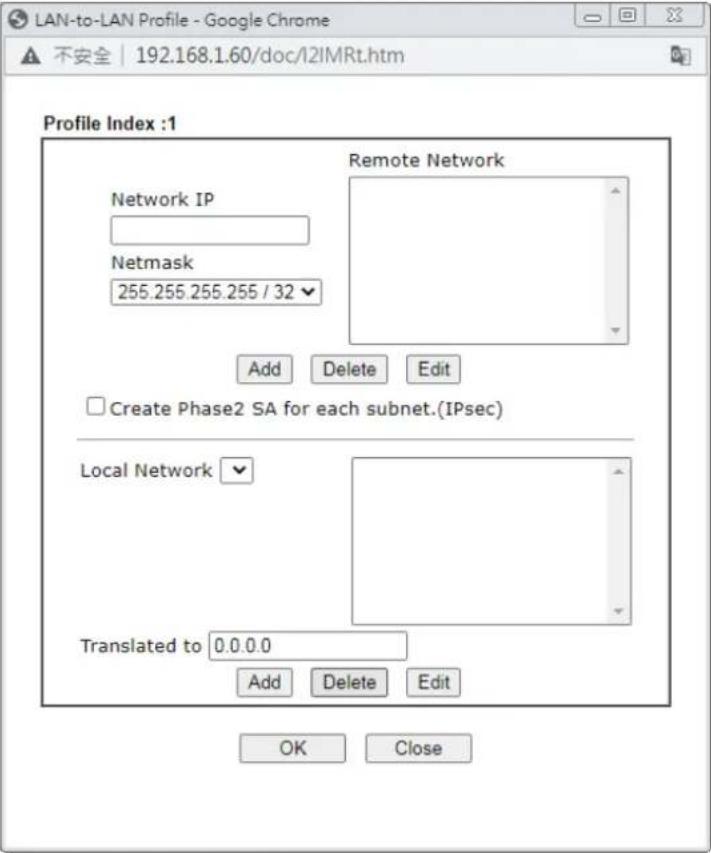 Translated Type - There are two types for you to choose. Translated Type - There are two types for you to choose. |
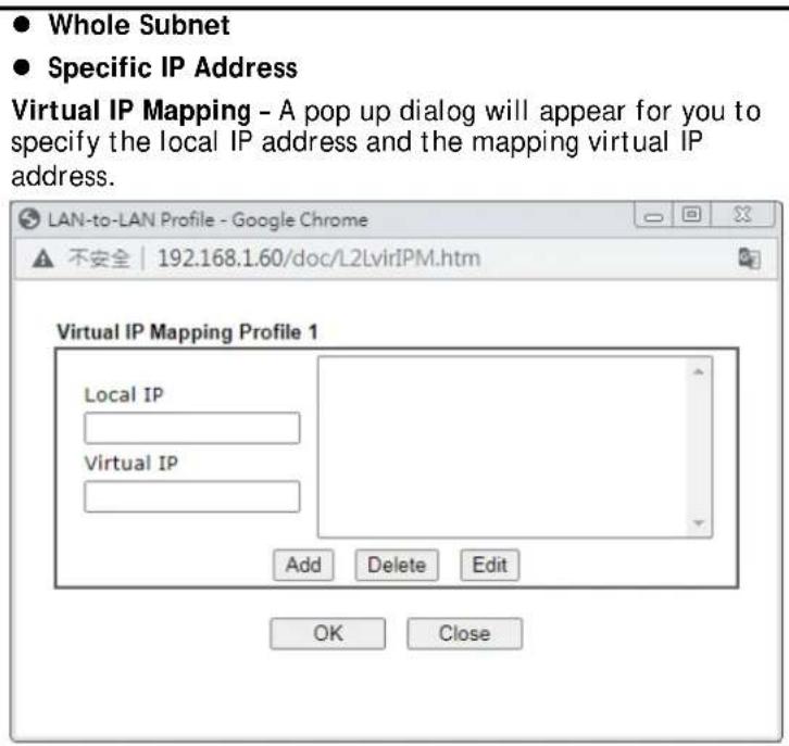
text_image
● Whole Subnet ● Specific IP Address Virtual IP Mapping - A pop up dialog will appear for you to specify the local IP address and the mapping virtual IP address. LAN-to-LAN Profile - Google Chrome ▲ 不安全 | 192.168.1.60/doc/L2LvirIPM.htm Virtual IP Mapping Profile 1 Local IP Virtual IP Add Delete Edit OK Close- After finishing all the settings here, please click OK to save the configuration.
IV-1-11 Connection Management
You can find the summary table of all VPN connections. You may disconnect any VPN connection by clicking Drop button. You may also aggressively Dial-out by using Dial-out Tool and clicking Dial button.
VPN and Remote Access >> Connection Management

text_image
Dial-out Tool Dial | Refresh |VPN Connection Status
| All VPN Status | LAN-to-LAN VPN Status | Remote Dial-in User Status | ||||||
| VPN | Type | Remote IP | Virtual Network | Tx Pkts | Tx Rate(bps) | Rx Pkts | Rx Rate(bps) | UpTime |
xxxxxxxx : Data is encrypted.
xxxxxxxx : Data isn't encrypted.
Available settings are explained as follows:
| Item | Description |
| Dial-out Tool This filed displays the profile configured in LAN-to-LAN (with Index number and VPN Server IP address). The VPN connection built by General Mode does not support VPN backup function.Dial - Click this button to execute dial out function. | |
IV-2 SSL VPN
An SSL VPN (Secure Sockets Layer virtual private network) is a form of VPN that can be used with a standard Web browser.
There are two benefits that SSL VPN provides:
- It is not necessary for users to preinstall VPN client software for executing SSL VPN connection.
- There are less restrictions for the data encrypted through SSL VPN in comparing with traditional VPN.
Web User Interface
SSL VPN
General Setup
User Account
SSL Portal Online User
N-2-1 General Setup
This page determines the general configuration for SSL VPN Server and SSL Tunnel.
SSL VPN >> SSL General Setup
SSL General Setup

text_image
Bind to WAN WAN2 LTE Port 443 (Default: 443) Server Certificate self-signedOK
Cancel
Available settings are explained as follows:
| Item | Description |
| Bind to WAN Choose and check WAN interface(s) for SSL VPN tunnel establishment. | |
| Port | Such port is set for SSL VPN server. It will not affect the HTTPS Port configuration set in System Maintenance>>Management. In general, the default setting is 443. |
| Server Certificate When the client does not set any certificate, default certificate will be used for HTTPS and SSL VPN server. Choose any one of the user-defined certificates from the drop down list if users set several certificates previously. Otherwise, choose Self-signed to use the router's built-in default certificate. The default certificate can be used in SSL VPN server and HTTPS Web Proxy. | |
After finishing all the settings here, please click OK to save the configuration.
IV-2-2 User Account
With SSL VPN, VigorLTE 200 series let teleworkers have convenient and simple remote access to central site VPN. The teleworkers do not need to install any VPN software manually. From regular web browser, you can establish VPN connection back to your main office even in a guest network or web cafe. The SSL technology is the same as the encryption that you use for secure web sites such as your online bank. The SSL VPN can be operated in either full tunnel mode or proxy mode. Now, VigorLTE 200 series allows up to 16 simultaneous incoming users.
For SSL VPN, identity authentication and power management are implemented through deploying user accounts. Therefore, the user account for SSL VPN must be set together with remote dial-in user web page. Such menu item will guide to access into VPN and Remote Access>>Remote Dial-in user.
VPN and Remote Access >> Remote Dial-in User

Remote Access User Accounts:
Set to Factory Default
| Index Enable | User | Status | Index Enable | User | Status | ||
| 1. | ??? | --- | 17. | ??? | --- | ||
| 2. | ??? | --- | 18. | ??? | --- | ||
| 3. | ??? | --- | 19. | ??? | --- | ||
| 4. | ??? | --- | 20. | ??? | --- | ||
| 5. | ??? | --- | 21. | ??? | --- | ||
| 6. | ??? | --- | 22. | ??? | --- | ||
| 7. | ??? | --- | 23. | ??? | --- | ||
| 8. | ??? | --- | 24. | ??? | --- | ||
| 9. | ??? | --- | 25. | ??? | --- | ||
| 10. | ??? | --- | 26. | ??? | --- | ||
| 11. | ??? | --- | 27. | ??? | --- | ||
| 12. | ??? | --- | 28. | ??? | --- | ||
| 13. | ??? | --- | 29. | ??? | --- | ||
| 14. | ??? | --- | 30. | ??? | --- | ||
| 15. | ??? | --- | 31. | ??? | --- | ||
| 16. | ??? | --- | 32. | ??? | --- | ||

Download Smart VPN Client:

Smart VPN Client for Windows

Smart VPN Client for Mobile (Android/iOS)

Smart VPN Client for MacOS
Click each index to edit one remote user profile.
VPN and Remote Access >> Remote Dial-in User
Index No. 1
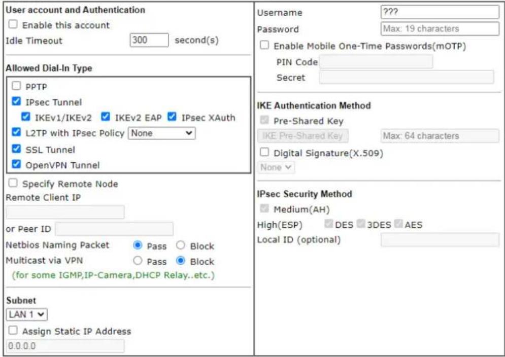
text_image
User account and Authentication Enable this account Idle Timeout 300 second(s) Allowed Dial-In Type PPTP IPsec Tunnel IKEv1/IKEv2 IKEv2 EAP IPsec XAuth L2TP with IPsec Policy None SSL Tunnel OpenVPN Tunnel Specify Remote Node Remote Client IP or Peer ID Netbios Naming Packet Pass Block Multicast via VPN Pass Block (for some IGMP,IP-Camera,DHCP Relay..etc.) Subnet LAN 1 Assign Static IP Address 0.0.0.0 Username ???? Password Max: 19 characters Enable Mobile One-Time Passwords(mOTP) PIN Code Secret IKE Authentication Method Pre-Shared Key IKE Pre-Shared Key Max: 64 characters Digital Signature(X.509) None IPsec Security Method Medium(AH) High(ESP) DES 3DES AES Local ID (optional)Note:
- Username can not contain characters ' \ " and \ ».
- OpenVPN tunnel does not support mOTP.
- When your are trying to use OpenVPN tunnel and the router is behind NAT, you may have to enable the VPN-Matcher feature to bypass the NAT.
- VPN-Matcher can only be used behind Cone NAT.

Available settings are explained as follows:
| Item | Description |
| User account and Authentication | Enable this account - Check the box to enable this function.Idle Timeout- If the dial-in user is idle over the limitation of the timer, the router will drop this connection. By default, the Idle Timeout is set to 300 seconds.Usage - This field is applicable when you select PPTP or L2TP with or without IPsec policy above. The length of the name/ password is limited to 23 characters.Password - This field is applicable when you select PPTP or L2TP with or without IPsec policy above. The length of the name/ password is limited to 19 characters.Enable Mobile One-Time Passwords (mOTP) - Check this box to make the authentication with mOTP function.PIN Code - Enter the code for authentication (e.g, 1234).Secret - Use the 32 digit-secret number generated by mOTP in the mobile phone (e.g., e759bb6f0e94c7ab4fe6). |
| Allowed Dial-In Type | PPTP - Allow the remote dial-in user to make a PPTP VPN connection through the Internet. You should set the User Name and Password of remote dial-in user below.IPSec Tunnel - Allow the remote dial-in user to make an IPSecVPN connection through Internet.L2TP with IPSec Policy - Allow the remote dial-in user to make a L2TP VPN connection through the Internet. You can select to use L2TP alone or with IPSec. Select from below:None- Do not apply the IPSec policy. Accordingly, the VPN connection employed the L2TP without IPSec policy can be viewed as one pure L2TP connection.Nice to Have- Apply the IPSec policy first, if it is applicable during negotiation. Otherwise, the dial-in VPN connection becomes one pure L2TP connection.Must-Specify the IPSec policy to be definitely applied on the L2TP connection.SSL Tunnel - It allows the remote dial-in user to make an SSL VPN Tunnel connection through Internet, suitable for the application through network accessing (e.g., PPTP / L2TP / IPSec).If you check this box, the function of SSL Tunnel for this account will be activated immediately.IPsec XAuth- Allow the remote dial-in user to make an IPsec VPN connection through XAuth server in Internet.Specify Remote Node- Check the checkbox to specify the IP address of the remote dial-in user, ISDN number or peer ID (used in IKE aggressive mode). If you uncheck the checkbox, the connection type you select above will apply the authentication methods and security methods in thegeneralsettings.Netbios Naming PacketPass- Click it to have an inquiry for data transmission between the hosts located on both sides of VPN Tunnel while connecting.Block- When there is conflict occurred between the hosts on both sides of VPN Tunnel in connecting, such function can block data transmission of Netbios Naming Packet inside the tunnel.Multicast via VPN- Some programs might send multicast packets via VPN connection.Pass- Click this button to let multicast packets pass through the router.Block- This is default setting. Click this button to let multicast packets be blocked by the router. |
| Subnet | Chose one of the subnet selections for such VPN profile.Assign Static IP Address- Please type a static IP address for the subnet you specified. |
| IKE Authentication Method | This group of fields is applicable for IPSec Tunnels and L2TP with IPSec Policy when you specify the IP address of the remote node. The only exception is Digital Signature (X.509) can be set when you select IPSec tunnel either with or without specify the IP address of the remote node.Pre-Shared Key- Check the box of Pre-Shared Key to invoke this function and Enter the required characters (1-63) as the pre-shared key.Digital Signature (X.509)- Check the box of Digital Signature to invoke this function and Select one predefined Profiles setin the VPN and Remote Access >>IPSec Peer Identity. |
| IPSec Security Method | This group of fields is a must for IPSec Tunnels and L2TP with IPSec Policy when you specify the remote node. Check the Medium, DES, 3DES or AES box as the security method.Medium-Authentication Header (AH) means data will be authenticated, but not be encrypted. By default, this option is invoked. You can uncheck it to disable it.High(ESP-Encapsulating Security Payload) means payload (data) will be encrypted and authenticated. You may select encryption algorithm from Data Encryption Standard (DES), Triple DES (3DES), and AES.Local ID - Specify a local ID to be used for Dial-in setting in the LAN-to-LAN Profile setup. This item is optional and can be used only in IKE aggressive mode. |
After finishing all the settings here, please click OK to save the configuration.
IV-2-3 SSL Portal Online User
If you have finished the configuration of SSL Web Proxy (server), users can find out corresponding settings when they access into DrayTek SSL VPN portal interface.
DrayTek
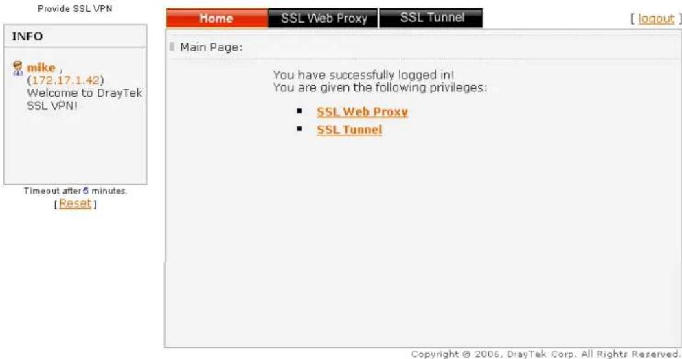
text_image
Provide SSL VPN INFO mike, (172.17.1.42) Welcome to DrayTek SSL VPN! Timeout after 5 minutes. [Reset] Home SSL Web Proxy SSL Tunnel Main Page: You have successfully logged in! You are given the following privileges: ■ SSL Web Proxy ■ SSL Tunnel Copyright © 2006, DrayTek Corp. All Rights Reserved.Next, users can open SSL VPN>> Online Status to view logging status of SSL VPN.
SSL VPN >> Online User Status
| Refresh Seconds : 5 refresh | |||
| Active User | Host IP | Time out(seconds) | Action |
| Kate | 192.168.30.14 | 299 | Drop |
Available settings are explained as follows:
| Item | Description |
| Active User | Display current user who visits SSL VPN server. |
| Host IP Display the IP address for the host. | |
| Time out Display the time | remaining for logging out. |
| Action | You can click Drop to drop certain login user from the router's SSL Portal UI. |
IV-3 Certificate Management
A digital certificate works as an electronic ID, which is issued by a certification authority (CA). It contains information such as your name, a serial number, expiration dates etc., and the digital signature of the certificate-issuing authority so that a recipient can verify that the certificate is real. Here Vigor router support digital certificates conforming to standard X.509.
Any entity wants to utilize digital certificates should first request a certificate issued by a CA server. It should also retrieve certificates of other trusted CA servers so it can authenticate the peer with certificates issued by those trusted CA servers.
Here you can manage generate and manage the local digital certificates, and set trusted CA certificates. Remember to adjust the time of Vigor router before using the certificate so that you can get the correct valid period of certificate.
Below shows the menu items for Certificate Management.
Web User Interface
Certificate Management
Local Certificate
Trusted CA Certificate
Certificate Backup
IV-3-1 Local Certificate
Certificate Management >> Local Certificate
X509 Local Certificate Configuration
| Name | Subject | Status | Modify | |
| --- | --- | --- | View | Delete |
| --- | --- | --- | View | Delete |
| --- | --- | --- | View | Delete |
Note:
- Please setup the "System Maintenance >> Time and Date" correctly before signing the local certificate.
- The Time Zone MUST be setup correctly!!
GENERATE IMPORT REFRESH
Available settings are explained as follows:
| Item | Description |
| Generate | Click this button to open Generate Certificate Request window.Enter all the information that the window requests. Then click Generate again. |
| Import Click this button to | import a saved file as the certification information. |
| Refresh Click this button to | to refresh the information listed below. |
| View Click this button to view the detailed settings for certificate request. | |
| Delete Click this button to | delete selected name with certification information. |
GENERATE
Click this button to open Generate Certificate Signing Request window. Enter all the information that the window request such as certificate name (used for identifying different certificate), subject alternative name type and relational settings for subject name. Then click GENERATE again.
Certificate Management >> Local Certificate
Generate Certificate Signing Request
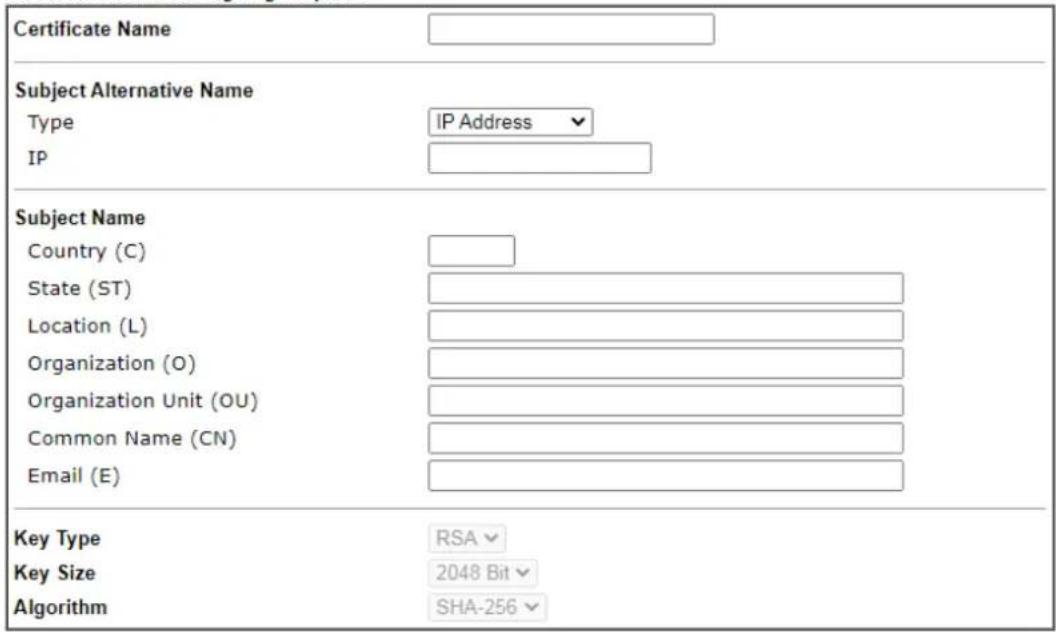
text_image
Certificate Name Subject Alternative Name Type IP Address IP Subject Name Country (C) State (ST) Location (L) Organization (O) Organization Unit (OU) Common Name (CN) Email (E) Key Type RSA Key Size 2048 Bit Algorithm SHA-256Generate

Info
Please be noted that "Common Name" must be configured with router's WAN IP or domain name.
After clicking GENERATE, the generated information will be displayed on the window below:
Certificate Management >> Local Certificate
X509 Local Certificate Configuration
| Name | Subject | Status | Modify | |
| server | /C=TW/ST=Hsinchu/L=Hsinchu/O... | Requesting | View Delete | |
| --- | --- | --- | View Delete | |
| --- | --- | --- | View Delete | |
GENERATE IMPORT REFRESH
IMPORT
Vigor router allows you to generate a certificate request and submit it the CA server, then import it as "Local Certificate". If you have already gotten a certificate from a third party, you may import it directly. The supported types are PKCS12 Certificate and Certificate with a private key.
Click this button to import a saved file as the certification information. There are three types of local certificate supported by Vigor router.
Import X509 Local Certificate
Upload Local Certificate
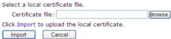
text_image
Select a local certificate file. Certificate file: Browse. Click Import to upload the local certificate. Import CancelUpload PKCS12 Certificate
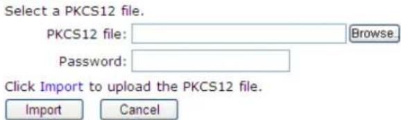
text_image
Select a PKCS12 file. PKCS12 file: Browse... Password: Click Import to upload the PKCS12 file. Import CancelUpload Certificate and Private Key
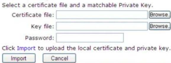
text_image
Select a certificate file and a matchable Private Key. Certificate file: Browse.. Key file: Browse.. Password: Click Import to upload the local certificate and private key. Import CancelAvailable settings are explained as follows:
| Item | Description |
| Upload Local Certificate | It allows users to import the certificate which is generated by Vigor router and signed by CA server.If you have done well in certificate generation, the Status of the certificate will be shown as “OK”.Import X509 Local Certificate X509 Local Certificate Configuration X509 Local Certificate Configuration GENERATE IMPORT REFRESH GENERATE IMPORT REFRESH |
| Upload PKCS12 Certificate | It allows users to import the certificate whose extensions are usually .pfx or .p12. And these certificates usually need passwords.Note that PKCS12 is a standard for storing private keys and certificates securely. It is used in (among other things) Netscape and Microsoft Internet Explorer with their import and export options. |
| Upload Certificate and Private Key | It is useful when users have separated certificates and private keys. And the password is needed if the private key is encrypted. |
REFRESH
Click this button to refresh the information listed below.
View
Click this button to view the detailed settings for certificate request.
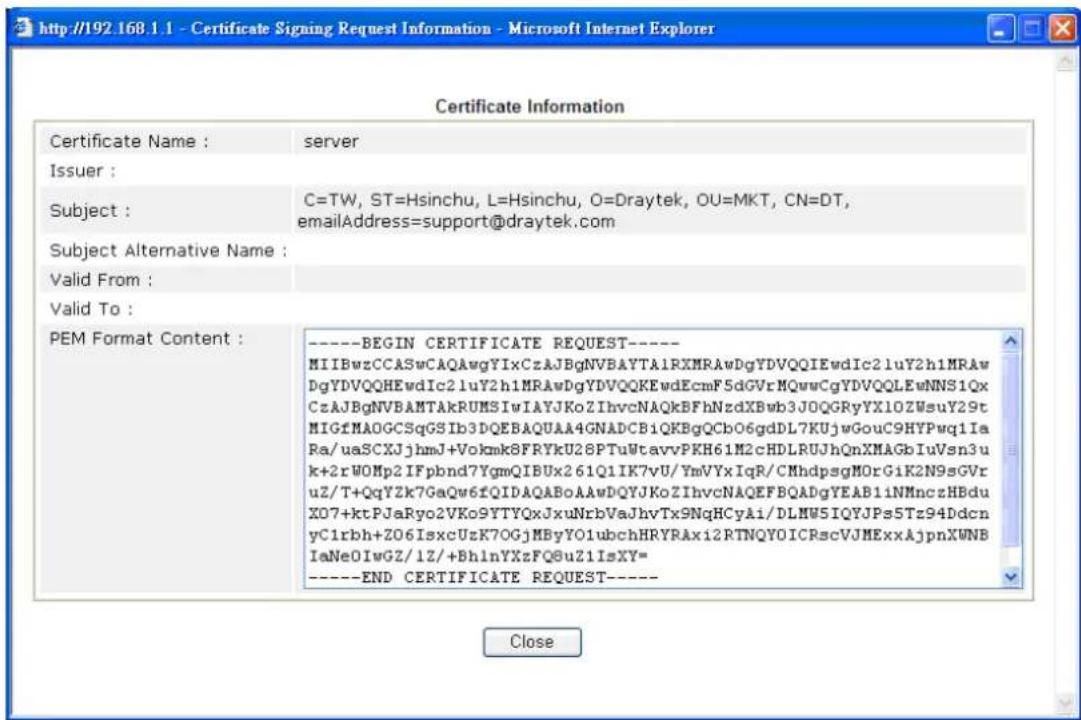
text_image
Certificate Information Certificate Name : server Issuer : Subject : C=TW, ST=Hsinchu, L=Hsinchu, O=Draytek, OU=MKT, CN=DT, emailAddress=support@draytek.com Subject Alternative Name : Valid From : Valid To : PEM Format Content : ----BEGIN CERTIFICATE REQUEST---- MIIBwzCCASwCAQAwgYIxCzAJBgNVBAYTA1RXMRAwDgYDVQQIEwdIc21uY2h1MRAw DgYDVQQHEwdIc21uY2h1MRAwDgYDVQQKEwdEcmF5dGVrMQwwCgYDVQQLEwNNS1Qx CzAJBgNVBAMTAkRUMSIwIAYJKoZIhvcNAQkBFhNzdXBwb3J0QGRyYX10ZWsuY29t MIGfMAOGCSqGSIb3DQEBAQUAA4GNADCB1QKBgQCbO6gdDL7KUjwGouC9HYPwq1Ia Ra/uaSCXJjhmJ+Vokmk8FRYkU28PTuWtavvPKH61M2cHDLRUJhQnXMAGbIuVsn3u k+2rWOMp2IFpbnd7YgmQIBUx261Q1IK7vU/YmVYxIqR/CMhdpsgMOrGiK2N9sGVr uZ/T+QqYZk7GaQw6fQIDAQABoAAwDQYJKoZIhvcNAQEFBQADgYEAB1iNMnczHBdu X07+ktPJaRyo2VKo9YTYQxJxuNrbVaJhvTx9NqHCyAi/DLMW5IQYJPs5Tz94Ddcn yC1rbh+Z06IsxcUzK70GjMByYO1ubchHRYRAxi2RTNQYOICRscVJMExxAjpnXWNB IaNe0IwGZ/1Z/+BhInYXzFQ8uZ1IsXY= ----END CERTIFICATE REQUEST---- Close
Info
You have to copy the certificate request information from above window. Next, access your CA server and enter the page of certificate request, copy the information into it and submit a request. A new certificate will be issued to you by the CA server. You can save it.
Delete
Click this button to remove the selected certificate.
IV-3-2 Trusted CA Certificate
Trusted CA certificate lists three sets of trusted CA certificate. In addition, you can build a RootCA certificate if required.
When the local client and remote client are required to make certificate authentication (e.g., IPsec X.509) for data passing through SSL tunnel and avoiding the attack of MITM, a trusted root certificate authority (Root CA) will be used to authenticate the digital certificates offered by both ends.
However, the procedure of applying digital certificate from a trusted root certificate authority is complicated and time-consuming. Therefore, Vigor router offers a mechanism which allows you to generate root CA to save time and provide convenience for general user. Later, such root CA generated by DrayTek server can perform the issuing of local certificate.

Info
Root CA can be deleted but not edited. If you want to modify the settings for a Root CA, please delete the one and create another one by clicking Create Root CA.
Certificate Management >> Trusted CA Certificate
X509 Trusted CA Certificate Configuration
| Name | Subject | Status | Modify | |
| Root CA | --- | --- | Create | |
| Trusted CA-1 | --- | --- | View | Delete |
| Trusted CA-2 | --- | --- | View | Delete |
| Trusted CA-3 | --- | --- | View | Delete |
Note:
- Please setup the "System Maintenance >> Time and Date" correctly before you try to generate a RootCA!!
- The Time Zone MUST be setup correctly!!
IMPORT REFRESH
Creating a Root CA
Click Create to open the following page. Enter all the information that the window request such as certificate name (used for identifying different certificate), subject alternative name type and relational settings for subject name. Then click Generate again.
Generate Root CA
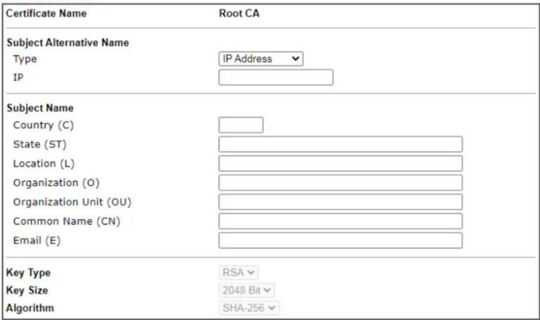
text_image
Certificate Name Root CA Subject Alternative Name Type IP Address IP Subject Name Country (C) State (ST) Location (L) Organization (O) Organization Unit (OU) Common Name (CN) Email (E) Key Type RSA Key Size 2048 Bit Algorithm SHA-256Generate
Importing a Trusted CA
To import a pre-saved trusted CA certificate, please click IMPORT to open the following window. Use Browse... to find out the saved text file. Then click Import. The one you imported will be listed on the Trusted CA Certificate window.
Certificate Management >> Trusted CA Certificate
Import X509 Trusted CA Certificate

text_image
Select a trusted CA certificate file. Browse Click Import to upload the certification. Import CancelFor viewing each trusted CA certificate, click View to open the certificate detail information window. If you want to delete a CA certificate, choose the one and click Delete to remove all the certificate information.
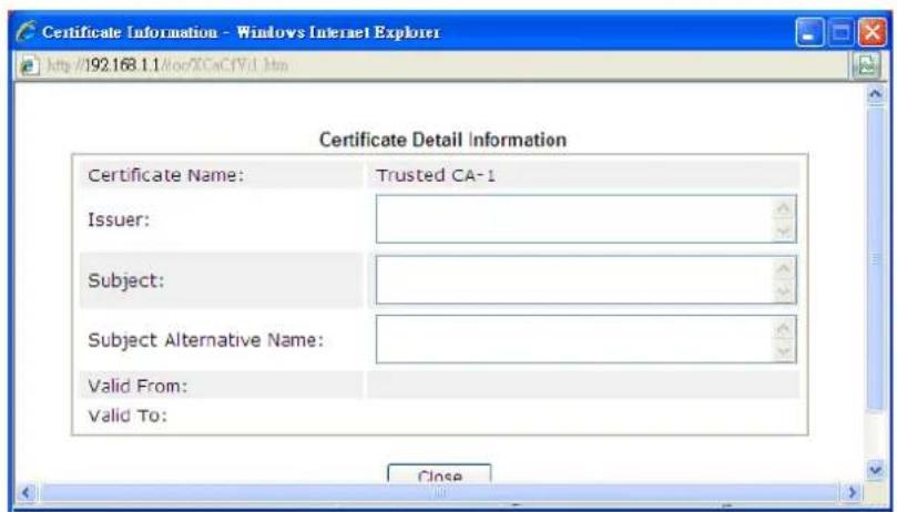
text_image
Certificate Information - Windows Internet Explorer http://192.168.1.1/doc/XXaCfV3.htm Certificate Detail Information Certificate Name: Trusted CA-1 Issuer: Subject: Subject Alternative Name: Valid From: Valid To:IV-3-3 Certificate Backup
Local certificate and Trusted CA certificate for this router can be saved within one file. Please click Backup on the following screen to save them. If you want to set encryption password for these certificates, please type characters in both fields of Encrypt password and Confirm password.
Also, you can use Restore to retrieve these two settings to the router whenever you want.
Certificate Management >> Certificate Backup
Certificate Backup / Restoration
Backup

text_image
Encrypt password: Confirm password: Click Backup to download certificates to your local PC as a file.Restoration
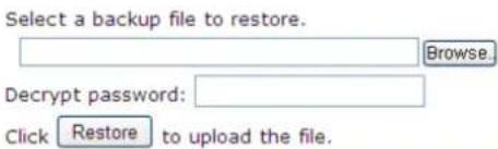
text_image
Select a backup file to restore. Browse... Decrypt password: Click Restore to upload the file.Available settings are explained as follows:
| Item | Description |
| Backup | |
| Encrypt password/Confirm password | Enter the password with which you wish to encrypt the certificate. |
| Backup Click to download | the certificate. |
| Restoration | |
| Select a backup file to restore | Click Browse to select the backup file you wish to restore. |
| Decrypt password Enter the password that was used to encrypt the certificates. | |
| Restore Click to retrieve the certificate. | |
Part V Security

Firewall
While the broadband users demand more bandwidth for multimedia, interactive applications, or distance learning, security has been always the most concerned. The firewall of the Vigor router helps to protect your local network against attack from unauthorized outsiders. It also restricts users in the local network from accessing the Internet.

CSM
CSM is an abbreviation of Central Security Management which is used to control IM/ P2P usage, filter the web content and URL content to reach a goal of security management.
V-1 Firewall
While the broadband users demand more bandwidth for multimedia, interactive applications, or distance learning, security has been always the most concerned. The firewall of the Vigor router helps to protect your local network against attack from unauthorized outsiders. It also restricts users in the local network from accessing the Internet. Furthermore, it can filter out specific packets that trigger the router to build an unwanted outgoing connection.
Firewall Facilities
The users on the LAN are provided with secured protection by the following firewall facilities:
- User-configurable IP filter (Call Filter/ Data Filter).
● Stateful Packet Inspection (SPI): tracks packets and denies unsolicited incoming data - Selectable Denial of Service (DoS) / Distributed DoS (DDoS) attacks protection
IP Filters
Depending on whether there is an existing Internet connection, or in other words "the WAN link status is up or down", the IP filter architecture categorizes traffic into two: Call Filter and Data Filter.
- Call Filter - When there is no existing Internet connection, Call Filter is applied to all traffic, all of which should be outgoing. It will check packets according to the filter rules. If legal, the packet will pass. Then the router shall "initiate a call" to build the Internet connection and send the packet to Internet.
- Data Filter - When there is an existing Internet connection, Data Filter is applied to incoming and outgoing traffic. It will check packets according to the filter rules. If legal, the packet will pass the router.
The following illustrations are flow charts explaining how router will treat incoming traffic and outgoing traffic respectively.
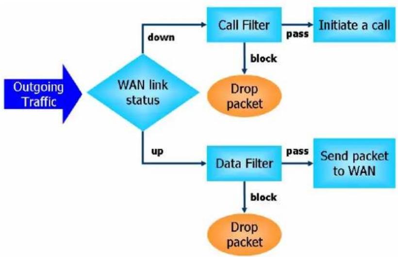
flowchart
graph TD
    A["Outgoing Traffic"] --> B{WAN link status}
    B -->|down| C["Call Filter"]
    B -->|up| D["Data Filter"]
    C -->|pass| E["Initiate a call"]
    C -->|block| F["Drop packet"]
    D -->|pass| G["Send packet to WAN"]
    D -->|block| H["Drop packet"]
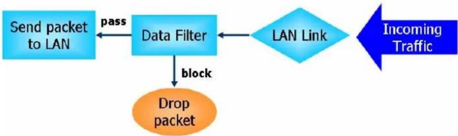
flowchart
graph TD
    A["Send packet to LAN"] -->|pass| B["Data Filter"]
    B -->|block| C["Drop packet"]
    C --> D["LAN Link"]
    D --> E["Incoming Traffic"]
Stateful Packet Inspection (SPI)
Stateful inspection is a firewall architecture that works at the network layer. Unlike legacy static packet filtering, which examines a packet based on the information in its header, stateful inspection builds up a state machine to track each connection traversing all interfaces of the firewall and makes sure they are valid. The stateful firewall of Vigor router not only examines the header information also monitors the state of the connection.
Denial of Service (DoS) Defense
The DoS Defense functionality helps you to detect and mitigate the DoS attack. The attacks are usually categorized into two types, the flooding-type attacks and the vulnerability attacks. The flooding-type attacks will attempt to exhaust all your system's resource while the vulnerability attacks will try to paralyze the system by offending the vulnerabilities of the protocol or operation system.
The DoS Defense function enables the Vigor router to inspect every incoming packet based on the attack signature database. Any malicious packet that might duplicate itself to paralyze the host in the secure LAN will be strictly blocked and a Syslog message will be sent as warning, if you set up Syslog server.
Also the Vigor router monitors the traffic. Any abnormal traffic flow violating the pre-defined parameter, such as the number of thresholds, is identified as an attack and the Vigor router will activate its defense mechanism to mitigate in a real-time manner.
The below shows the attack types that DoS/ DDoS defense function can detect:
- SYN flood attack
- UDP flood attack
- ICMP flood attack
- Port Scan attack
- IP options
- Land attack
- Smurf attack
-
Trace route
-
SYN fragment
-
Fraggle attack
-
TCP flag scan
-
Tear drop attack
-
Ping of Death attack
-
ICMP fragment
-
Unassigned Numbers
Web User Interface
Below shows the menu items for Firewall.
Firewall
General Setup
Filter Setup
Defense Setup
V-1-1 General Setup
General Setup allows you to adjust settings of IP Filter and common options. Here you can enable or disable the Call Filter or Data Filter. Under some circumstance, your filter set can be linked to work in a serial manner. So here you assign the Start Filter Set only. Also you can configure the Log Flag settings, Apply IP filter to VPN incoming packets, and Accept incoming fragmented UDP packets.
Click Firewall and click General Setup to open the general setup page.
General Setup Page
Such page allows you to enable / disable Call Filter and Data Filter, determine general rule for filtering the incoming and outgoing data.
Firewall >> General Setup
General Setup
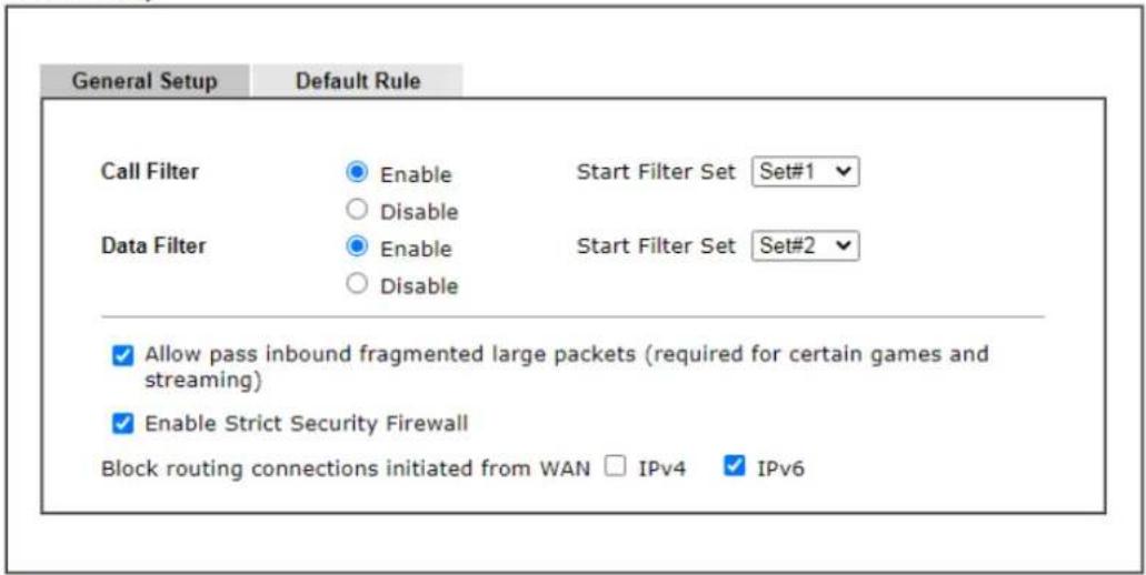
text_image
General Setup Default Rule Call Filter Enable Start Filter Set Set#1 Data Filter Enable Start Filter Set Set#2 Allow pass inbound fragmented large packets (required for certain games and streaming) Enable Strict Security Firewall Block routing connections initiated from WAN □ IPv4 ✓ IPv6Note:
Packets are filtered by firewall functions in the following order:
- Data Filter Sets and Rules 2. Block routing connections initiated from WAN 3. Default Rule

This will not backup the detail setting of Quality of Service and Schedule.
Available settings are explained as follows:
| Item | Description |
| Call Filter | Check Enable to activate the Call Filter function. Assign a start filter set for the Call Filter. |
| Data Filter | Check Enable to activate the Data Filter function. Assign a start filter set for the Data Filter. |
| Always pass inbound fragmented large packets... | Some on-line games (for example: Half Life) will use lots of fragmented UDP packets to transfer game data. Instinctively as a secure firewall, Vigor router will reject these fragmented packets to prevent attack unless you enable “Always pass inbound fragmented large packets...”. By checking this box, you can play these kinds of on-line games. If security concern is in higher priority, you cannot enable “Always pass inbound fragmented large packets...”. |
| Enable Strict Security Firewall | For the sake of security, the router will execute strict security checking for data transmission.Such feature is enabled in default. All the packets, while transmitting through Vigor router, will be filtered by firewall. If the firewall system (e.g., content filter server) does not make any response (pass or block) for these packets, then the router’s firewall will block the packets directly. |
| Block routing connections initiated from WAN | Usually, IPv6 network sessions/ traffic from WAN to LAN will be accepted by IPv6 firewall in default.IPv6 - To prevent remote client accessing into the PCs on LAN, check the box to make the packets (routed from WAN to LAN) via IPv6 being blocked by such router. It is effective only for the packets routed but not for packets translated by NAT.IPv4 - To prevent remote client accessing into the PCs on LAN, check the box to make the incoming packets via IPv4 being blocked by such router. It is effective only for the packets routed but not for packets translated by NAT. |
| Backup Firewall | Click Backup to save the firewall configuration. |
| Restore Firewall | Click Select to choose a firewall configuration file. Then click Restore to apply the file. |
Default Rule Page
Such page allows you to choose filtering profiles including QoS, Load-Balance policy, WCF, APP Enforcement, URL Content Filter, for data transmission via Vigor router.
Firewall >> General Setup
General Setup
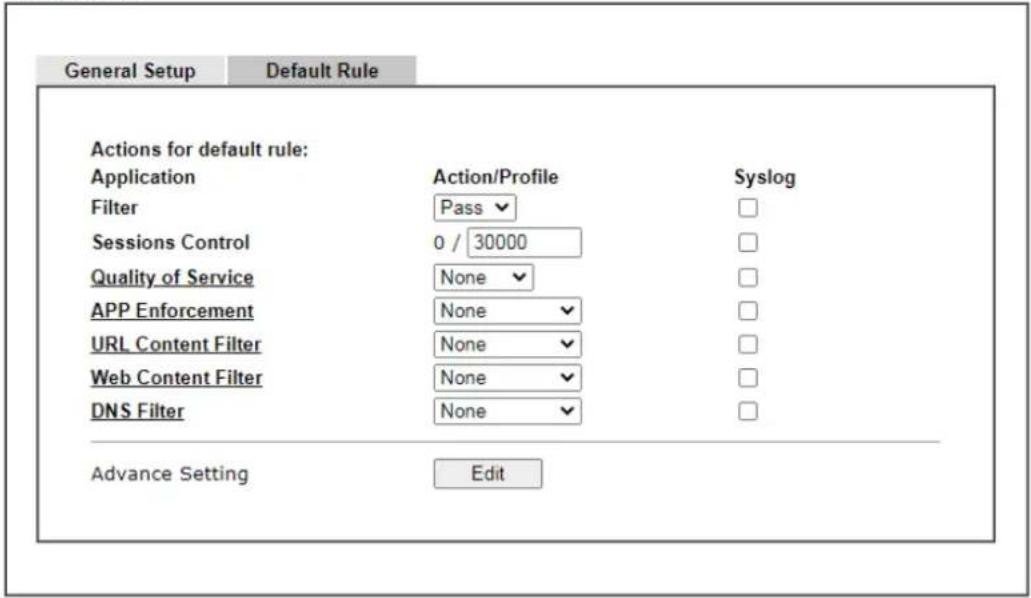
text_image
General Setup Default Rule Actions for default rule: Application Action/Profile Syslog Filter Pass Sessions Control 0 / 30000 Quality of Service None APP Enforcement None URL Content Filter None Web Content Filter None DNS Filter None Advance Setting Edit
This will not backup the detail setting of Quality of Service and Schedule.
Available settings are explained as follows:
| Item | Description |
| Filter | Select Pass or Block for the packets that do not match with the filter rules. |
| Sessions Control The number | er typed here is the total sessions of the packets that do not match the filter rule configured in this page. The default setting is 60000. |
| Quality of Service Choose | one of the QoS rules to be applied as firewall rule.For detailed information of setting QoS, please refer to the related section later. |
| APP Enforcement | Select an APP Enforcement profile for global IM/ P2P application blocking. If there is no profile for you to select, please choose [Create New] from the drop down list in this page to create a new profile. All the hosts in LAN must follow the standard configured in the APP Enforcement profile selected here. For detailed information, refer to the section of APP Enforcement profile setup. For troubleshooting needs, you can specify to record information for IM/ P2P by checking the Log box. It will be sent to Syslog server. Please refer to section Syslog/Mail Alert for more detailedinformation. |
| URL Content Filter | Select one of the URL Content Filter profile settings (created in CSM>> URL Content Filter) for applying with this router. Please set at least one profile for choosing in CSM>> URL Content Filter web page first. Or choose [Create New] from the drop down list in this page to create a new profile. For troubleshooting needs, you can specify to record information for URL Content Filter by checking the Log box. It will be sent to Syslog server. Please refer to section Syslog/Mail Alert for more detailed information. |
| Web Content Filter | Select one of the Web Content Filter profile settings (created in CSM>> Web Content Filter) for applying with this router. Please set at least one profile for anti-virus in CSM>> Web Content Filter web page first. Or choose [Create New] from the drop down list in this page to create a new profile. For troubleshooting needs, you can specify to record information for Web Content Filter by checking the Log box. It will be sent to Syslog server. Please refer to section Syslog/Mail Alert for more detailed information. |
| DNS Filter | Select the DNS Filter profile to be used, or None to disable DNS Filter for the Default Rule. Select [Create New] from the dropdown list to create a new profile.Syslog - Select to allow DNS Filter to log messages in Syslog. Logging action is configured at the profile level in the DNS Filter Profile Table section in CSM>>DNS Filter Profile, SysLog. |
| Advance Setting | Click Edit to open the following window. However, it is strongly recommended to use the default settings here.Firewall >> General Setup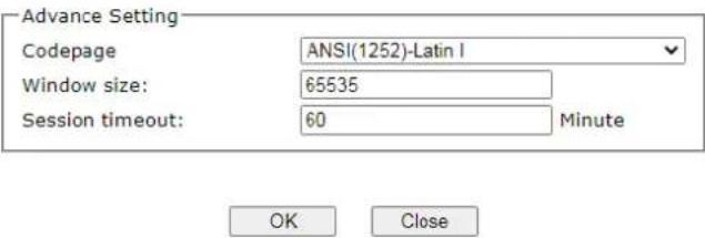 Codepage - This function is used to compare the characters among different languages. Choose correct codepage can help the system obtain correct ASCII after decoding data from URL and enhance the correctness of URL Content Filter. The default value for this setting is ANSI 1252 Latin I. If you do not choose any codepage, no decoding job of URL will be processed. Please use the drop-down list to choose a codepage.If you do not have any idea of choosing suitable codepage, please open Syslog. From Codepage Information of Setup dialog, you will see the recommended codepage listed on the dialog box. Codepage - This function is used to compare the characters among different languages. Choose correct codepage can help the system obtain correct ASCII after decoding data from URL and enhance the correctness of URL Content Filter. The default value for this setting is ANSI 1252 Latin I. If you do not choose any codepage, no decoding job of URL will be processed. Please use the drop-down list to choose a codepage.If you do not have any idea of choosing suitable codepage, please open Syslog. From Codepage Information of Setup dialog, you will see the recommended codepage listed on the dialog box.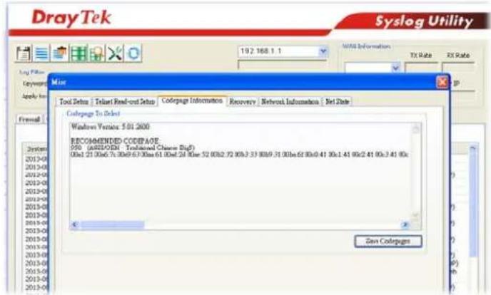 |
| Window size - It determines the size of TCP protocol (0~65535). The more the value is, the better the performance will be. However, if the network is not stable, small value will be proper.Session timeout - Setting timeout for sessions can make the best utilization of network resources. | |
| Backup Firewall | Click Backup to save the firewall configuration. |
| Restore Firewall | Click Select to choose a firewall configuration file. Then click Restore to apply the file. |
After finishing all the settings here, please click OK to save the configuration.
V-1-2 Filter Setup
Click Firewall and click Filter Setup to open the setup page.
Firewall >> Filter Setup
| Filter Setup | Set to Factory Default | ||
| Set | Comments | Set | Comments |
| 1. | Default Call Filter | 7. | |
| 2. | Default Data Filter | 8. | |
| 3. | 9. | ||
| 4. | 10. | ||
| 5. | 11. | ||
| 6. | 12. | ||
To edit or add a filter, click on the set number to edit the individual set. The following page will be shown. Each filter set contains up to 7 rules. Click on the rule number button to edit each rule. Check Active to enable the rule.
Firewall >> Filter Setup >> Edit Filter Set
Filter Set 1
Comments: Default Call Filter
| Rule | Enable | Comments | Direction | Src IP | Dst IP | Service Type | Action | CSM | Move Up | Move Down |
| 1 | Block NetBios | LAN/RT/VPN->WAN | Any | Any | TCP/UDP, Port: from 137~139 to any | Block Immediately | Down | |||
| 2 | LAN/RT/VPN->WAN | Any | Any | Any | Pass Immediately | UP | Down | |||
| 3 | LAN/RT/VPN->WAN | Any | Any | Any | Pass Immediately | UP | Down | |||
| 4 | LAN/RT/VPN->WAN | Any | Any | Any | Pass Immediately | UP | Down | |||
| 5 | LAN/RT/VPN->WAN | Any | Any | Any | Pass Immediately | UP | Down | |||
| 6 | LAN/RT/VPN->WAN | Any | Any | Any | Pass Immediately | UP | Down | |||
| 7 | LAN/RT/VPN->WAN | Any | Any | Any | Pass Immediately | UP |
Filter Set 1 2 3 4 5 6 7 8 9 10 11 12
Next Filter Set None
○ Wizard Mode: most frequently used settings in three pages
Advance Mode: all settings in one page
OK Clear Cancel
Available settings are explained as follows:
| Item | Description |
| Rule Click a button numbered (1 ~ 7) to edit the filter rule. Click the button will open Edit Filter Rule web page. For the detailed information, refer to the following page. | |
| Enable Check the box to enable the filter rule. | |
| Comments | Enter filter set comments/ description. Maximum length is 23-character long. |
| Direction Display the direction of packet. | |
| Src IP / Dst IP Display the IP address of source / destination. | |
| Service Type Display the type and port number of the packet. | |
| Action Display the packets to be passed / blocked. | |
| CSM Display the content security managed | |
| Move Up/Down | Use Up or Down link to move the order of the filter rules. |
| Next Filter Set Set the link to the next filter set to be executed after the current filter run. Do not make a loop with many filter sets. | |
| Wizard Mode | Allow to configure frequently used settings for filter rule via several setting pages. |
| Advance Mode | Allow to configure detailed settings of filter rule. |
To use Wizard Mode, simple do the following steps:
-
Click the Wizard Mode radio button.
-
Click Index 1. The setting page will appear as follows:
Firewall >> Edit Filter Set >> Edit Filter Rule Wizard
Filter Set 1 Rule 1
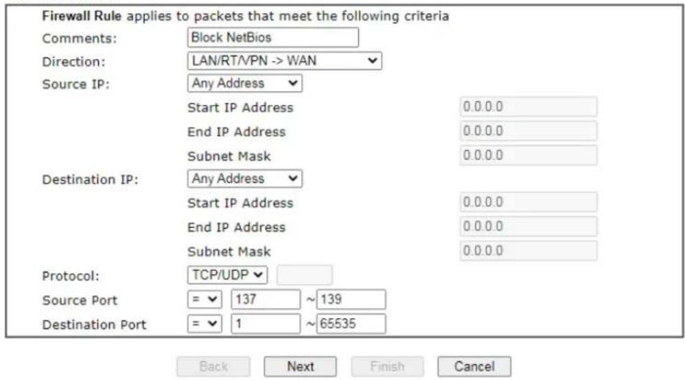
text_image
Firewall Rule applies to packets that meet the following criteria Comments: Block NetBios Direction: LAN/RT/VPN -> WAN Source IP: Any Address Start IP Address 0.0.0.0 End IP Address 0.0.0.0 Subnet Mask 0.0.0.0 Destination IP: Any Address Start IP Address 0.0.0.0 End IP Address 0.0.0.0 Subnet Mask 0.0.0.0 Protocol: TCP/UDP Source Port = 137 ~ 139 Destination Port = 1 ~ 65535 Back Next Finish CancelAvailable settings are explained as follows:
| Item | Description |
| Comments | Enter filter set comments/ description. Maximum length is 14- character long. |
| Direction | Set the direction of packet flow. It is for Data Filter only. For the Call Filter, this setting is not available since Call Filter is only applied to outgoing traffic.Note: RT means routing domain for 2nd subnet or other LAN. |
| Source/Destination IP | To set the IP address manually, please choose Any Address/Single Address/Range Address/Subnet Address as the Address Type and Enter them in this dialog. |
| Protocol | Specify the protocol(s) which this filter rule will apply to. |
| Source Port / Destination Port | (=) - when the first and last value are the same, it indicates one port; when the first and last values are different, it indicates a range for the port and available for this service type.(!=) - when the first and last value are the same, it indicates all the ports except the port defined here; when the first and last values are different, it indicates that all the ports except the range defined here are available for this service type.(>) - the port number greater than this value is available. (<) - the port number less than this value is available for this profile. |
3. Click Next to get the following page.
Firewall >> Edit Filter Set >> Edit Filter Rule Wizard
Filter Set 1 Rule 1
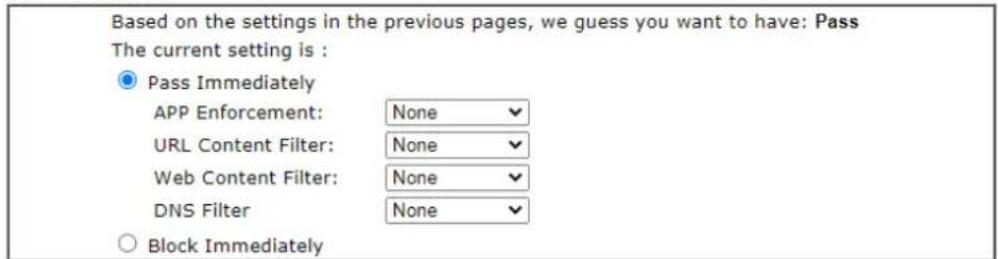
text_image
Based on the settings in the previous pages, we guess you want to have: Pass The current setting is : ● Pass Immediately APP Enforcement: None ✓ URL Content Filter: None ✓ Web Content Filter: None ✓ DNS Filter None ✓ ○ Block Immediately
Available settings are explained as follows:
| Item | Description |
| Pass Immediately Packets matching the rule will be passed immediately.APP Enforcement - Select an APP Enforcement profile for application blocking, or None to disable APP Enforcement for the Default Rule. Select [Create New] from the dropdown list to create a new profile. Refer to the chapter on APP Enforcement for more details on the feature.URL Content Filter - Select a URL Content Filter profile to be used, or None to disable URL Content Filter for the Default Rule. Select [Create New] from the dropdown list to create a new profile. Refer to the chapter on URL Content Filter for more details on the feature.Web Content Filter - Select a Web Content Filter profile to be used, or None to disable Web Content Filter for the Default Rule. Select [Create New] from the dropdown list to create a new profile.DNS Filter - Select the DNS Filter profile to be used, or None to disable DNS Filter for the Default Rule. Select [Create New] from the dropdown list to create a new profile. | |
| Block Immediately Packets matching the rule will be dropped immediately. |
- After choosing the mechanism, click Next to get the summary page for reference.
Firewall >> Edit Filter Set >> Edit Filter Rule Wizard
Filter Set 1 Rule 1 Configuration Summary
| Comments : | Block NetBios | |
| Direction | ||
| LAN/RT/VPN -> WAN | ||
| Criteria | ||
| Source IP | Any | |
| Destination IP | Any | |
| Protocol | TCP/UDP, Port: from 137 ~ 139 to any | |
| More options | ||
| Pass Immediately | ||
| APP Enforcement : None | ||
| URL Content Filter : None | ||
| Web Content Filter : None | ||
| DNS Filter : None | ||

- If there is no error, click Finish to complete wizard setting.
To use Advance Mode, do the following steps:
-
Click the Advance Mode radio button.
-
Click Index 1 to access into the following page.
Firewall >> Edit Filter Set >> Edit Filter Rule
Filter Set 1 Rule 1
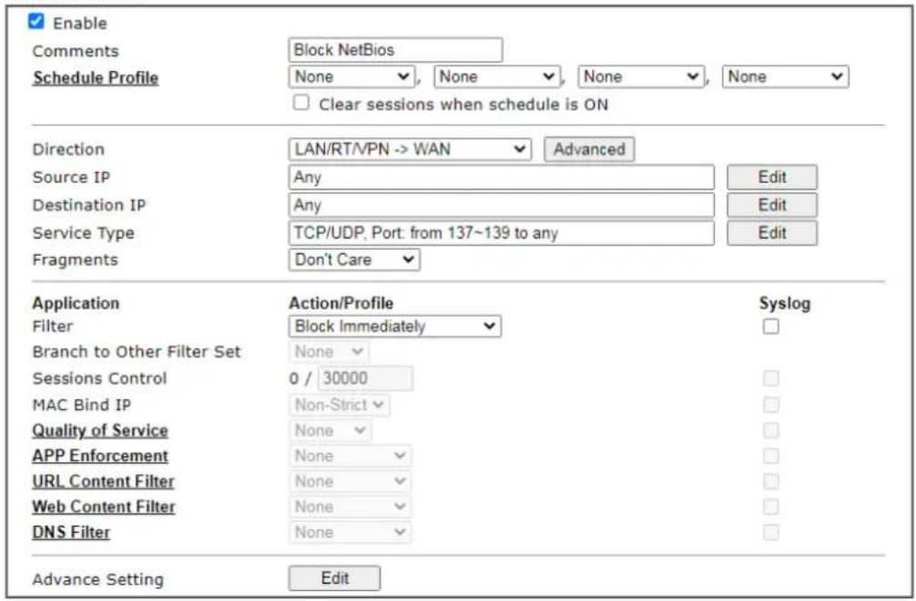
text_image
Enable Comments Block NetBios Schedule Profile None , None , None , None Clear sessions when schedule is ON Direction LAN/RT/VPN -> WAN Advanced Source IP Any Edit Destination IP Any Edit Service Type TCP/UDP, Port: from 137~139 to any Edit Fragments Don't Care Application Action/Profile Syslog Filter Block Immediately Branch to Other Filter Set None Sessions Control 0 / 30000 MAC Bind IP Non-Strict Quality of Service None APP Enforcement None URL Content Filter None Web Content Filter None DNS Filter None Advance Setting Edit
Available settings are explained as follows:
| Item | Description |
| Enable Check this box to enable the filter rule. | |
| Comments | Enter filter set comments/ description. Maximum length is 14- character long. |
| Schedule Profile Set PCs on LAN to work at certain time interval only. You may choose up to 4 schedules out of the 15 schedules pre-defined in Applications >> Schedule setup. The default setting of this field is blank and the function will always work. | |
| Clear sessions when schedule ON | Check this box to clear the sessions when the above schedule profiles are applied. |
| Direction | Set the direction of packet flow. It is for Data Filter only. For the Call Filter, this setting is not available since Call Filter is only applied to outgoing traffic.LAN/RT/VPN -> WANLAN/RT/VPN -> WANWAN -> LAN/RT/VPNLAN/RT/VPN -> LAN/RT/VPNNote: RT means routing domain for 2nd subnet or other LAN.Advanced - After choosing the direction, click theAdvanced button to specify interfaces for traffic flow.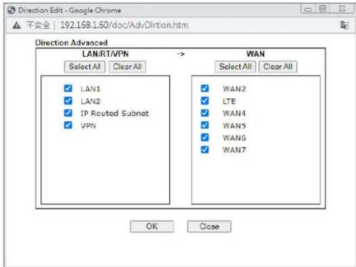 |
| Source/Destination IP | Click Edit to access into the following dialog to choose the source/destination IP or IP ranges.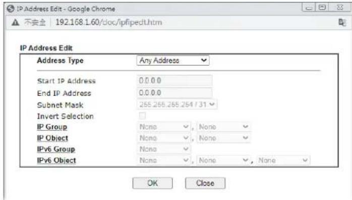 To set the IP address manually, please choose Any Address/Single Address/Range Address/Subnet Address as the Address Type and type them in this dialog. In addition, if you want to use the IP range from defined groups or objects, please choose Group and Objects as the Address Type.Group and ObjectsAny AddressSingle AddressRange AddressSubnet AddressGroup and ObjectsFrom the IP Group drop down list, choose the one that you want to apply. Or use the IP Object drop down list to choose the object that you want. To set the IP address manually, please choose Any Address/Single Address/Range Address/Subnet Address as the Address Type and type them in this dialog. In addition, if you want to use the IP range from defined groups or objects, please choose Group and Objects as the Address Type.Group and ObjectsAny AddressSingle AddressRange AddressSubnet AddressGroup and ObjectsFrom the IP Group drop down list, choose the one that you want to apply. Or use the IP Object drop down list to choose the object that you want. |
| Service Type | Click Edit to access into the following dialog to choose a suitable service type.[W A2 K]To set the service type manually, please chooseUser definedas the Service Type and type them in this dialog. In addition, if you want to use the service type from defined groups or objects, please chooseGroup and Objectsas the Service Type.User definedUser definedGroup and ObjectsProtocol - Specify the protocol(s) which this filter rule will apply to.Source/Destination Port -(=)- when the first and last value are the same, it indicates one port; when the first and last values are different, it indicates a range for the port and available for this service type.(!=)- when the first and last value are the same, it indicates all the ports except the port defined here; when the first and last values are different, it indicates that all the ports except the range defined here are available for this service type.(>)- the port number greater than this value is available.(<)- the port number less than this value is available for this profile.Service Group/Object - Use the drop down list to choose the one that you want. |
| Fragments Specify the action for fragmented packets. And it is used forData Filter only.Don't care-No action will be taken towards fragmented packets.Unfragmented -Apply the rule to unfragmented packets.Fragmented - Apply the rule to fragmented packets.Too Short - Apply the rule only to packets that are too short to contain a complete header. | |
| Filter Specifies the action to be taken when packets match the rule.Block Immediately - Packets matching the rule will be dropped immediately.Pass Immediately - Packets matching the rule will be passed immediately.Block If No Further Match - A packet matching the rule, and that does not match further rules, will be dropped.Pass If No Further Match - A packet matching the rule, and that does not match further rules, will be passed through. | |
| Branch to other Filter Set | If the packet matches the filter rule, the next filter rule will branch to the specified filter set. Select next filter rule to branch from the drop-down menu. Be aware that the router will apply the specified filter rule for ever and will not return to previous filter rule any more. |
| Sessions Control The number typed here is the total sessions of the packets that do not match the filter rule configured in this page. The default setting is 60000. | |
| MAC Bind IP | Strict - Make the MAC address and IP address settings configured in IP Object for Source IP and Destination IP are bound for applying such filter rule.No-Strict - no limitation. |
Quality of Service Choose one of the QoS rules to be applied as firewall rule. For detailed information of setting QoS, please refer to the related section later.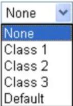 | |
| APP Enforcement | Select an APP Enforcement profile for global IM/ P2P application blocking. If there is no profile for you to select, please choose [Create New] from the drop down list in this page to create a new profile. All the hosts in LAN must follow the standard configured in the APP Enforcement profile selected here. For detailed information, refer to the section of APP Enforcement profile setup. For troubleshooting needs, you can specify to record information for IM/ P2P by checking the Log box. It will be sent to Syslog server. Please refer to section Syslog/Mail Alert for more detailed information. |
| URL Content Filter | Select one of the URL Content Filter profile settings (created in CSM>> URL Content Filter) for applying with this router. Please set at least one profile for choosing in CSM>> URL Content Filter web page first. Or choose [Create New] from the drop down list in this page to create a new profile. For troubleshooting needs, you can specify to record information for URL Content Filter by checking the Log box. It will be sent to Syslog server. Please refer to section Syslog/Mail Alert for more detailed information. |
| Web Content Filter | Select one of the Web Content Filter profile settings (created in CSM>> Web Content Filter) for applying with this router. Please set at least one profile for anti-virus in CSM>> Web Content Filter web page first. Or choose [Create New] from the drop down list in this page to create a new profile. For troubleshooting needs, you can specify to record information for Web Content Filter by checking the Log box. It will be sent to Syslog server. Please refer to section Syslog/Mail Alert for more detailed information. |
| DNS Filter | Select the DNS Filter profile to be used, or None to disable DNS Filter for the Default Rule. Select [Create New] from the dropdown list to create a new profile.Syslog - Select to allow DNS Filter to log messages in Syslog. Logging action is configured at the profile level in the DNSFilter Profile Table section in CSM>>DNS Filter Profile, SysLog. |
| Advance Setting | Click Edit to open the following window. However, it is strongly recommended to use the default settings here.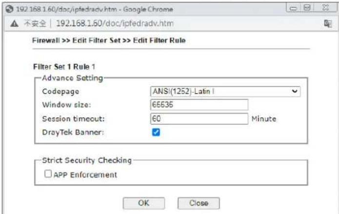 Codepage- This function is used to compare the characters among different languages. Choose correct codepage can help the system obtaining correct ASCII after decoding data from URL and enhance the correctness of URL Content Filter. The default value for this setting is ANSI 1252 Latin I. If you do not choose any codepage, no decoding job of URL will be processed. Please use the drop-down list to choose a codepage.If you do not have any idea of choosing suitable codepage, please open Syslog. From Codepage Information of Setup dialog, you will see the recommended codepage listed on the dialog box. Codepage- This function is used to compare the characters among different languages. Choose correct codepage can help the system obtaining correct ASCII after decoding data from URL and enhance the correctness of URL Content Filter. The default value for this setting is ANSI 1252 Latin I. If you do not choose any codepage, no decoding job of URL will be processed. Please use the drop-down list to choose a codepage.If you do not have any idea of choosing suitable codepage, please open Syslog. From Codepage Information of Setup dialog, you will see the recommended codepage listed on the dialog box.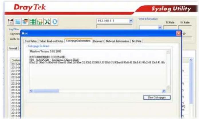 Window size- It determines the size of TCP protocol (0~65535). The more the value is, the better the performance will be. However, if the network is not stable, small value will be proper.Session timeout-Setting timeout for sessions can make the best utilization of network resources. However, Queue timeout is configured for TCP protocol only; session timeout is configured for the data flow which matched with the firewall rule.DrayTek Banner- Please uncheck this box and the following screen will not be shown for the unreachable web page. The default setting is Enabled. Window size- It determines the size of TCP protocol (0~65535). The more the value is, the better the performance will be. However, if the network is not stable, small value will be proper.Session timeout-Setting timeout for sessions can make the best utilization of network resources. However, Queue timeout is configured for TCP protocol only; session timeout is configured for the data flow which matched with the firewall rule.DrayTek Banner- Please uncheck this box and the following screen will not be shown for the unreachable web page. The default setting is Enabled. |
The requested Web page has been blocked by Web Content Filter.
Please contact your system administrator for further information.
[Powered by Draytek]
Strict Security Checking - All the packets, while transmitting through Vigor router, will be filtered by firewall settings configured by Vigor router. When the resource is inadequate, the packets will be blocked if Strict Security Checking is enabled. If Strict Security Checking is not enabled, then the packets will pass through the router.
- When you finish the configuration, please click OK to save and exit this page.
V-1-3 DoS Defense
As a sub-functionality of IP Filter/ Firewall, there are 15 types of detect/ defense function in the DoS Defense setup. The DoS Defense functionality is disabled for default.
V-1-3-1 DoS Defense
Click Firewall and click DoS Defense to open the setup page.
Firewall >> Defense Setup
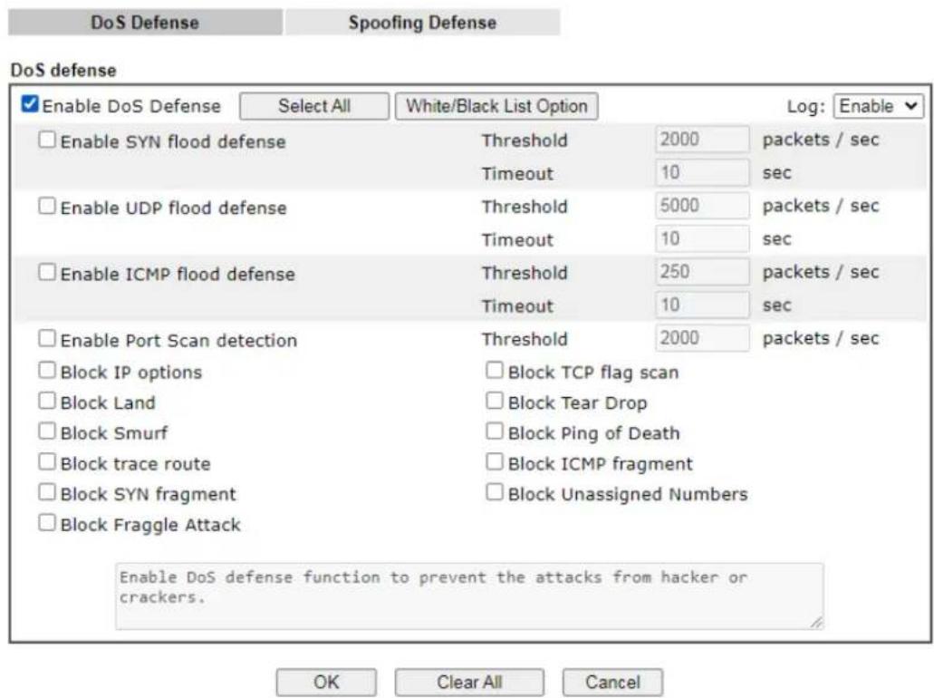
text_image
DoS Defense Spoofing Defense DoS defense Enable DoS Defense Select All White/Black List Option Log: Enable Enable SYN flood defense Threshold 2000 packets / sec Timeout 10 sec Enable UDP flood defense Threshold 5000 packets / sec Timeout 10 sec Enable ICMP flood defense Threshold 250 packets / sec Timeout 10 sec Enable Port Scan detection Threshold 2000 packets / sec Block IP options Block TCP flag scan Block Land Block Tear Drop Block Smurf Block Ping of Death Block trace route Block ICMP fragment Block SYN fragment Block Unassigned Numbers Block Fraggle Attack Enable DoS defense function to prevent the attacks from hacker or crackers. OK Clear All CancelAvailable settings are explained as follows:
| Item | Description |
| Enable Dos Defense Check the box to activate the DoS Defense Functionality.Select All - Click this button to select all the items listed below.White/Black List Option - Set white/ black list of IPv4/ IPv6 address. | |
| Enable SYN flood defense Check the box to activate the SYN flood defense function.Once detecting the Threshold of the TCP SYN packets from the Internet has exceeded the defined value, the Vigor router will start to randomly discard the subsequent TCP SYN packets for a period defined in Timeout. The goal for this is prevent the TCP SYN packets' attempt to exhaust the limited-resource of Vigor router.By default, the threshold and timeout values are set to 2000 packets per second and 10 seconds, respectively. That means, when 2000 packets per second received, they will be regarded as “attack event” and the session will be | |
| paused for 10 seconds. | |
| Enable UDP flood defense | Check the box to activate the UDP flood defense function.Once detecting the Threshold of the UDP packets from the Internet has exceeded the defined value, the Vigor router will start to randomly discard the subsequent UDP packets for a period defined in Timeout.The default setting for threshold and timeout are 2000 packets per second and 10 seconds, respectively. That means, when 2000 packets per second received, they will be regarded as “attack event” and the session will be paused for 10 seconds. |
| Enable ICMP flood defense | Check the box to activate the ICMP flood defense function.Similar to the UDP flood defense function, once if the Threshold of ICMP packets from Internet has exceeded the defined value, the router will discard the ICMP echo requests coming from the Internet.The default setting for threshold and timeout are 250 packets per second and 10 seconds, respectively. That means, when 250 packets per second received, they will be regarded as “attack event” and the session will be paused for 10 seconds. |
| Enable Port Scan detection | Port Scan attacks the Vigor router by sending lots of packets to many ports in an attempt to find ignorant services would respond. Check the box to activate the Port Scan detection. Whenever detecting this malicious exploration behavior by monitoring the port-scanning Threshold rate, the Vigor router will send out a warning.By default, the Vigor router sets the threshold as 2000 packets per second. That means, when 2000 packets per second received, they will be regarded as “attack event”. |
| Block IP options Check the | box to activate the Block IP options function.The Vigor router will ignore any IP packets with IP option field in the datagram header. The reason for limitation is IP option appears to be a vulnerability of the security for the LAN because it will carry significant information, such as security, TCC (closed user group) parameters, a series of Internet addresses, routing messages...etc. An eavesdropper outside might learn the details of your private networks. |
| Block Land | Check the box to enforce the Vigor router to defense the Land attacks. The Land attack combines the SYN attack technology with IP spoofing. A Land attack occurs when an attacker sends spoofed SYN packets with the identical source and destination addresses, as well as the port number to victims. |
| Block Smurf Check the box | to activate the Block Smurf function. The Vigor router will ignore any broadcasting ICMP echo request. |
| Block trace route | Check the box to enforce the Vigor router not to forward any trace route packets. |
| Block SYN fragment Check | the box to activate the Block SYN fragment function.The Vigor router will drop any packets having SYN flag and more fragment bit set. |
| Block Fraggle Attack | Check the box to activate the Block fraggle Attack function.Any broadcast UDP packets received from the Internet isblocked.Activating the DoS/ DDoS defense functionality might block some legal packets. For example, when you activate the fragile attack defense, all broadcast UDP packets coming from the Internet are blocked. Therefore, the RIP packets from the Internet might be dropped. |
| Block TCP flag scan Check the | the box to activate the Block TCP flag scan function.Any TCP packet with anomaly flag setting is dropped. Those scanning activities include no flag scan, FIN without ACK scan, SYN FINscan, Xmas scan and full Xmas scan. |
| Block Tear Drop Check the | box to activate the Block Tear Drop function.Many machines may crash when receiving ICMP datagrams (packets) that exceed the maximum length. To avoid this type of attack, the Vigor router is designed to be capable of discarding any fragmented ICMP packets with a length greater than 1024 octets. |
| Block Ping of Death Check the | the box to activate the Block Ping of Death function.This attack involves the perpetrator sending overlapping packets to the target hosts so that those target hosts will hang once they re-construct the packets. The Vigor routers will block any packets realizing this attacking activity. |
| Block ICMP Fragment Check | the box to activate the Block ICMP fragment function. Any ICMP packets with more fragment bit set are dropped. |
| Block Unassigned Numbers | Check the box to activate the Block Unknown Protocol function. Individual IP packet has a protocol field in the datagram header to indicate the protocol type running over the upper layer. However, the protocol types greater than 100 are reserved and undefined at this time. Therefore, the router should have ability to detect and reject this kind of packets. |
| Warning Messages We provide | Syslog function for user to retrieve message from Vigor router. The user, as a Syslog Server, shall receive the report sending from Vigor router which is a Syslog Client.All the warning messages related to DoS Defense will be sent to user and user can review it through Syslog daemon. Look for the keyword DoS in the message, followed by a name to indicate what kind of attacks is detected.System Maintenance >> SysLog / Mail Alert Setup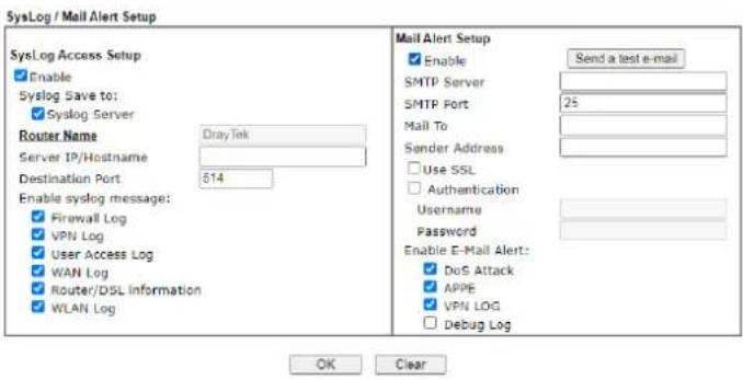 |
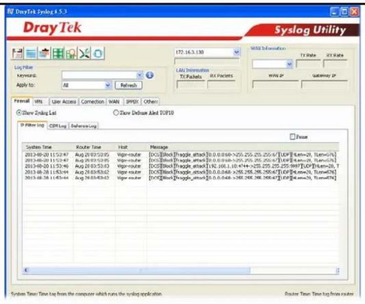
text_image
DrayTek Syslog 4.5.3 Syslog Utility Log Filter Keywords: Apply to: All Refresh 172.16.3.130 LAN Information TX Packets RX Packets WASI Information TX Rate RX Rate WWW IP Gateway IP Formal VRL User Access Connection WAN BPIX Other Show Debug List Show Default Linked TCP10 IP Filter log CSM Log DefenseLog System Time Router Time Host Message 2013-08-20 11:52:47 Aug 28 03:53:05 Vager-router [0CS][Block] [truggle_attack] [0.0.0.0.68->255.255.255.67] [UCF] [Len=20, Len=676] 2013-08-20 11:53:47 Aug 28 03:53:45 Vager-router [0CS][Block] [truggle_attack] [0.0.0.0.68->255.255.255.67] [UCF] [Len=20, Len=676] 2013-08-20 11:53:46 Aug 28 03:53:43 Vager-router [0CS][Block] [truggle_attack] [192, 168, 1, 10, 44++->255.255.255.255.997] [UCF] [Len=20, T] 2013-08-28 11:53:44 Aug 28 03:53:42 Vager-router [0CS][Block] [truggle_attack] [0.0.0.0.68->255.255.255.67] [UCF] [Len=20, Len=676] 2013-08-28 11:45:44 Aug 28 03:53:43 Vager-router [0CS][Block] [truggle_attack] [0.0.0.0.68->255.255.255.67] [UCF] [Len=20, Len=676] System Time: Time tag from the computer which runs the syslog application. Router Time: Time tag from routesAfter finishing all the settings here, please click OK to save the configuration.
V-1-3-2 Spoofing Defense
Click the Spoofing Defense tab to open the setup page.
Firewall >> Defense Setup
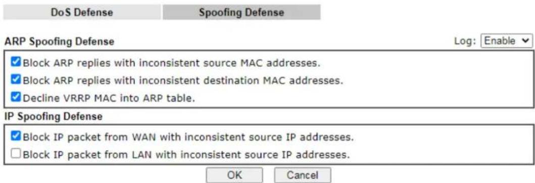
text_image
DoS Defense Spoofing Defense ARP Spoofing Defense Log: Enable ✓ Block ARP replies with inconsistent source MAC addresses. ✓ Block ARP replies with inconsistent destination MAC addresses. ✓ Decline VRRP MAC into ARP table. IP Spoofing Defense ✓ Block IP packet from WAN with inconsistent source IP addresses. □ Block IP packet from LAN with inconsistent source IP addresses. OK CancelApplication Notes
A-1 How to Configure Certain Computers Accessing to Internet
We can specify certain computers (e.g., 192.168.1.10 \~ 192.168.1.20) accessing to Internet through Vigor router. Others (e.g., 192.168.1.31 and 192.168.1.32) outside the range can get the source from LAN only.
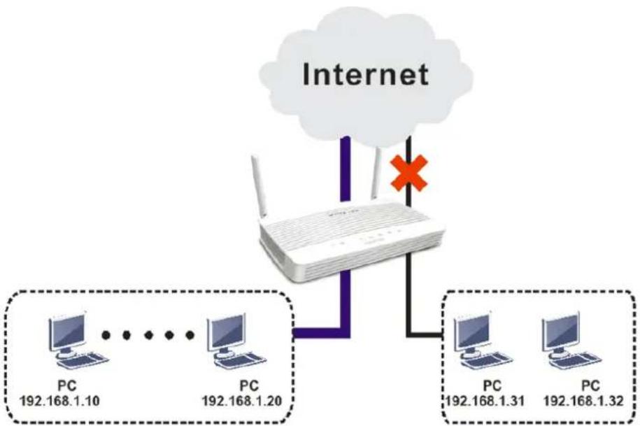
flowchart
graph TD
    A["Router"] -->|Internet| B["PC 192.168.1.10"]
    A -->|Internet| C["PC 192.168.1.20"]
    A -->|Internet| D["PC 192.168.1.31"]
    A -->|Internet| E["PC 192.168.1.32"]
The way we can use is to set two rules under Firewall. For Rule 1 of Set 2 under Firewall>>Filter Setup is used as the default setting, we have to create a new rule starting from Filter Rule 2 of Set 2.
- Access into the web user interface of Vigor router.
- Open Firewall>>Filter Setup. Click the Set 2 link, choose Advance Mode and choose the Filter Rule 2 button.
Firewall >> Filter Setup
| Set | Comments | Set | Comments |
| 1. | Default Call Filter | 7. | |
| 2. | Default Data Filter | 8. | |
| 9. | |||
| 10. | |||
| 11. | |||
| 6 | 12. |
flowchart
graph TD
    A["X"] --> B["Box"]
- Check the box of Check to enable the Filter Rule. Enter the comments (e.g., block_all). Choose Block If No Further Match for the Filter setting. Then, click OK.
Filter Set 2 Rule 2
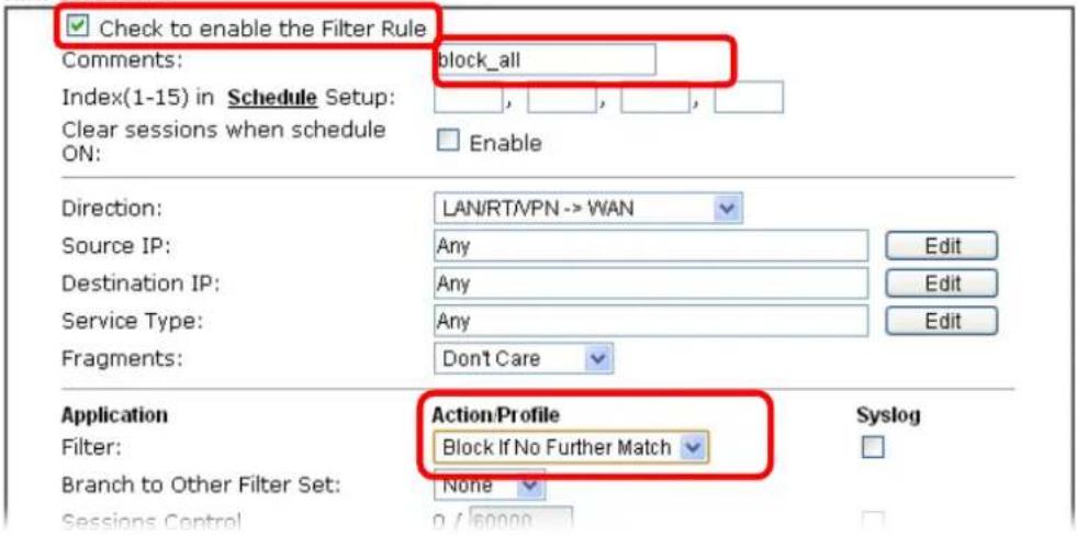
text_image
Check to enable the Filter Rule Comments: block_all Index(1-15) in Schedule Setup: Clear sessions when schedule ON: Enable Direction: LAN/RT/VPN -> WAN Source IP: Any Edit Destination IP: Any Edit Service Type: Any Edit Fragments: Don't Care Application Action Profile Filter: Block If No Further Match Branch to Other Filter Set: None Syslog Sessions Control 0 / 60000
Info
In default, the router will check the packets starting with Set 2, Filter Rule 2 to Filter Rule 7. If Block If No Further Match for is selected for Filter, the firewall of the router would check the packets with the rules starting from Rule 3 to Rule 7. The packets not matching with the rules will be processed according to Rule 2.
- Next, set another rule. Just open Firewall>>Filter Setup. Click the Set 2 link and choose the Filter Rule 3 button.
- Check the box of Check to enable the Filter Rule. Enter the comments (e.g., open_ip). Click the Edit button for Source IP.
Firewall >> Edit Filter Set >> Edit Filter Rule
Filter Set 2 Rule 3
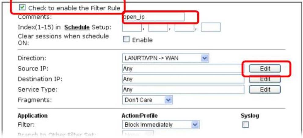
text_image
Check to enable the Filter Rule Comments: open_ip Index(1-15) in Schedule Setup: Clear sessions when schedule ON: Enable Direction: LAN/RT/VPN -> WAN Source IP: Any Edit Destination IP: Any Edit Service Type: Any Edit Fragments: Don't Care Application Action/Profile Syslog Filter: Block Immediately Branch to Other Filter Set:- A dialog box will be popped up. Choose Range Address as Address Type by using the drop down list. Type 192.168.1.10 in the field of Start IP, and type 192.168.1.20 in the field of End IP. Then, click OK to save the settings. The computers within the range can access into the Internet.
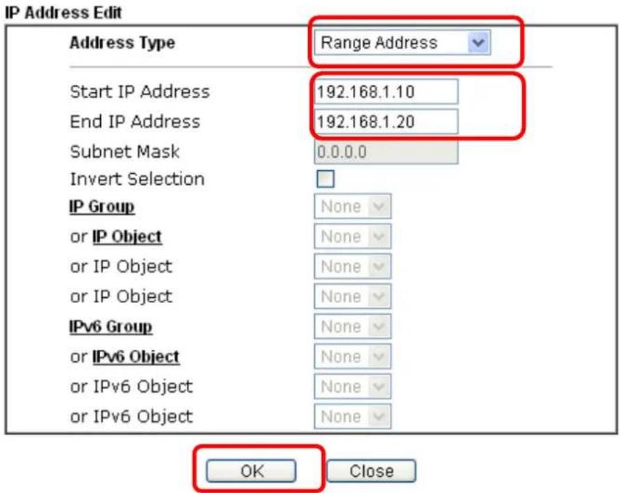
text_image
IP Address Edit Address Type Range Address Start IP Address 192.168.1.10 End IP Address 192.168.1.20 Subnet Mask 0.0.0.0 Invert Selection IP Group None or IP Object None or IP Object None or IP Object None IPv6 Group None or IPv6 Object None or IPv6 Object None or IPv6 Object None OK Close- Now, check the content of Source IP is correct or not. The action for Filter shall be set with Pass Immediately. Then, click OK to save the settings.
Firewall >> Edit Filter Set >> Edit Filter Rule
Filter Set 2 Rule 3
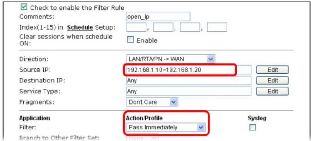
text_image
Check to enable the Filter Rule Comments: open_ip Index(1-15) in Schedule Setup: , , , , Clear sessions when schedule ON: Enable Direction: LAN/RT/PN -> WAN Source IP: 192.168.1.10~192.168.1.20 Edit Destination IP: Any Edit Service Type: Any Edit Fragments: Don't Care Application Action Profile Syslog Filter: Pass Immediately Branch to Other Filter Set: None8. Both filter rules have been created. Click OK.
Firewall >> Filter Setup >> Edit Filter Set
Filter Set 2
Comments
Default Data Filter
| Rule Enable | Comments | Direction | Src IP | Dst IP | Service Type | Action | CSM | Move Up | Move Down | |
| 1 | xNetBios -> DNS | LAN/RT/VPN -> WAN | Any | Any | TCP/UDP, Port: from 137~139 to 53 | Block Immediately | Down | |||
| 2 | block_all | LAN/RT/VPN -> WAN | Any | Any | [ CMP ] | Pass Immediately | UP | Down | ||
| 3 | open_ip | WAN -> LAN/RT/VPN | Any | Any | Any | Pass Immediately | UP | Down | ||
| 4 | LAN/RT/VPN -> WAN | Any | Any | Any | Pass Immediately | UP | Down | |||
| 5 | LAN/RT/VPN -> WAN | Any | Any | Any | Pass Immediately | UP | Down | |||
| 6 | LAN/RT/VPN -> WAN | Any | Any | Any | Pass Immediately | UP | Down | |||
| 7 | LAN/RT/VPN -> WAN | Any | Any | Any | Pass Immediately | UP | ||||
Filter Set 1 2 3 4 5 6 7 8 9 10 11 12
Next Filter Set None
○ Wizard Mode: most frequently used settings in three pages
- Advance Mode: all settings in one page
OK
Clear
Cancel
Now, all the settings are configured well. Only the computers with the IP addresses within 192.168.1.10 \~ 192.168.1.20 can access to Internet.
V-2 Central Security Management (CSM)
CSM is an abbreviation of Central Security Management which is used to control IM/ P2P usage, filter the web content and URL content to reach a goal of security management.
APP Enforcement Filter
As the popularity of all kinds of instant messenger application arises, communication cannot become much easier. Nevertheless, while some industry may leverage this as a great tool to connect with their customers, some industry may take reserved attitude in order to reduce employee misuse during office hour or prevent unknown security leak. It is similar situation for corporation towards peer-to-peer applications since file-sharing can be convenient but insecure at the same time. To address these needs, we provide CSM functionality.
URL Content Filter
To provide an appropriate cyberspace to users, Vigor router equips with URL Content Filter not only to limit illegal traffic from/ to the inappropriate web sites but also prohibit other web feature where malicious code may conceal.
Once a user Enter or click on an URL with objectionable keywords, URL keyword blocking facility will decline the HTTP request to that web page thus can limit user's access to the website. You may imagine URL Content Filter as a well-trained convenience-store clerk who won't sell adult magazines to teenagers. At office, URL Content Filter can also provide a job-related only environment hence to increase the employee work efficiency. How can URL Content Filter work better than traditional firewall in the field of filtering? Because it checks the URL strings or some of HTTP data hiding in the payload of TCP packets while legacy firewall inspects packets based on the fields of TCP/IP headers only.
On the other hand, Vigor router can prevent user from accidentally downloading malicious codes from web pages. It's very common that malicious codes conceal in the executable objects, such as ActiveX, Java Applet, compressed files, and other executable files. Once downloading these types of files from websites, you may risk bringing threat to your system. For example, an ActiveX control object is usually used for providing interactive web feature. If malicious code hides inside, it may occupy user's system.
Web Content Filter
We all know that the content on the Internet just like other types of media may be inappropriate sometimes. As a responsible parent or employer, you should protect those in your trust against the hazards. With Web filtering service of the Vigor router, you can protect your business from common primary threats, such as productivity, legal liability, network and security threats. For parents, you can protect your children from viewing adult websites or chat rooms.
Once you have activated your Web Filtering service in Vigor router and chosen the categories of website you wish to restrict, each URL address requested (e.g.www.bbc.co.uk) will be checked against our server database. This database is updated as frequent as daily by a global team of Internet researchers. The server will look up the URL and return a category to your router. Your Vigor router will then decide whether to allow access to this site according to the categories you have selected. Please note that this action will not introduce any delay in your Web surfing because each of multiple load balanced database servers can handle millions of requests for categorization.

Info
The priority of URL Content Filter is higher than Web Content Filter.
Web User Interface
CSM
APP Enforcement Profile
URL Content Filter Profile
Web Content Filter Profile
DNS Filter Profile
V-2-1 APP Enforcement Profile
You can define policy profiles for IM (Instant Messenger)/ P2P (Peer to Peer)/ Protocol/ Misc application. This page allows you to set 32 profiles for different requirements. The APP Enforcement Profile will be applied in Default Rule of Firewall>>General Setup for filtering.
CSM >> APP Enforcement Profile
| APP Enforcement Profile Table: | Set to Factory Default | ||
| Profile | Name | Profile | Name |
| 1. | 17. | ||
| 2. | 18. | ||
| 3. | 19. | ||
| 4. | 20. | ||
| 5. | 21. | ||
| 6. | 22. | ||
| 7. | 23. | ||
| 8. | 24. | ||
| 9. | 25. | ||
| 10. | 26. | ||
| 11. | 27. | ||
| 12. | 28. | ||
| 13. | 29. | ||
| 14. | 30. | ||
| 15. | 31. | ||
| 16. | 32. | ||
Available settings are explained as follows:
| Item | Description |
| Set to Factory Default Clear | all profiles. |
| Profile | Display the number of the profile which allows you to click to set different policy. |
| Name | Display the name of the APP Enforcement Profile. |
Click the number under Index column for settings in detail.
CSM >> APP Enforcement Profile
Profile Index : 1
Profile Name:
Clone Profile
| Category | Application | ||
| Instant Message | AIM Login | AliWW | Ares |
| BaiduHi | Facebook/Instagram | Fetion | |
| Select All | GaduGadu Protocol | ICQ | iSpQ |
| KC | LINE | ||
| Paltalk | PocoCall | Qnext | |
| Clear All | Signal | Slack | Snapchat |
| Telegram | Tencent QQ | UC | |
| WebIM URLs | |||
| VoIP | |||
| Select All | RC Voice | Skype | TeamSpeak |
| Clear All | TelTel | ||
| P2P | Ares | BitTorrent | ClubBox |
Available settings are explained as follows:
| Item | Description |
| Profile Name Type a name for the CSM profile. The maximum length of the name you can set is 15 characters. | |
| Select All Click it to choose all of the items in this page. | |
| Clear All Uncheck all the selected boxes. | |
| Enable Check the box to select the APP to be blocked by Vigor router. | |
The profiles configured here can be applied in the Firewall>>General Setup and Firewall>>Filter Setup pages as the standard for the host(s) to follow.
V-2-2 URL Content Filter Profile
To provide an appropriate cyberspace to users, Vigor router equips with URL Content Filter not only to limit illegal traffic from/ to the inappropriate web sites but also prohibit other web feature where malicious code may conceal.
Once a user Enter or click on an URL with objectionable keywords, URL keyword blocking facility will decline the HTTP request to that web page thus can limit user's access to the website. You may imagine URL Content Filter as a well-trained convenience-store clerk who won't sell adult magazines to teenagers. At office, URL Content Filter can also provide a job-related only environment hence to increase the employee work efficiency. How can URL Content Filter work better than traditional firewall in the field of filtering? Because it checks the URL strings or some of HTTP data hiding in the payload of TCP packets while legacy firewall inspects packets based on the fields of TCP/IP headers only.
On the other hand, Vigor router can prevent user from accidentally downloading malicious codes from web pages. It's very common that malicious codes conceal in the executable objects, such as ActiveX, Java Applet, compressed files, and other executable files. Once downloading these types of files from websites, you may risk bringing threat to your system. For example, an ActiveX control object is usually used for providing interactive web feature. If malicious code hides inside, it may occupy user's system.
For example, if you add key words such as "sex", Vigor router will limit web access to web sites or web pages such as "www.sex.com", "www.backdoor.net/images/sex/p_386.html". Or you may simply specify the full or partial URL such as "www.sex.com" or "sex.com".
Also the Vigor router will discard any request that tries to retrieve the malicious code.
Click CSM and click URL Content Filter Profile to open the profile setting page.
CSM >> URL Content Filter Profile

URL Content Filter Profile Table:
| Profile | Name | Profile | Name |
| 1. | 5. | ||
| 2. | 6. | ||
| 3. | 7. | ||
| 4. | 8. |
Note:
To make URL Content Filter profile effective, please go to Firewall >> Filter Setup page to create a firewall rule and select the desired profile.
The requested Web page has been blocked by URL Content Filter.
Please contact your system administrator for further information.
Administration Message (Max 255 characters)
Default Message
OK
Each item is explained as follows:
| Item | Description |
| Set to Factory Default Clear all profiles. | |
| Profile | Display the number of the profile which allows you to click to set different policy. |
| Name | Display the name of the URL Content Filter Profile. |
| Administration Message | You can Enter the message manually for your necessity.Default Message - You can Enter the message manually for your necessity or click this button to get the default message which will be displayed on the field of Administration Message. |
You can set eight profiles as URL content filter. Simply click the index number under Profile to open the following web page.
CSM >> URL Content Filter Profile
Profile Index: 1
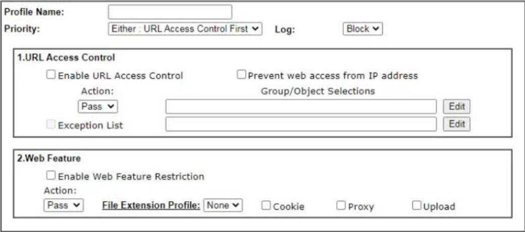
text_image
Profile Name: Priority: Either : URL Access Control First Log: Block 1.URL Access Control Enable URL Access Control Prevent web access from IP address Action: Group/Object Selections Pass Edit Exception List Edit 2.Web Feature Enable Web Feature Restriction Action: Pass File Extension Profile: None Cookie Proxy Upload
Available settings are explained as follows:
| Item | Description |
| Profile Name Type a name for the CSM profile. The maximum length of the name you can set is 15 characters. | |
| Priority It determines the action that this router will apply.Both: Pass - The router will let all the packages that match with the conditions specified in URL Access Control and Web Feature below passing through. When you choose this setting, both configuration set in this page for URL Access Control and Web Feature will be inactive.Both:Block -The router will block all the packages that match with the conditions specified in URL Access Control and Web Feature below. When you choose this setting, both configuration set in this page for URL Access Control and Web Feature will be inactive.Either: URL Access Control First - When all the packages matching with the conditions specified in URL Access Control and Web Feature below, such function can determine the priority for the actions executed. For this one, the router will process the packages with the conditions set below for URL first, then Web feature second.Either: Web Feature First -When all the packages matching with the conditions specified in URL Access Control and Web Feature below, such function can determine the priority for the actions executed. For this one, the router will process the packages with the conditions set below for web feature first, then URL second. | |
| Both : PassBoth : PassBoth : BlockEither : URL Access Control FirstEither : Web Feature First | ||
| Log | Pass - Only the log about Pass will be recorded in Syslog.Block - Only the log about Block will be recorded in Syslog.All - All the actions (Pass and Block) will be recorded in Syslog. | |
| URL Access Control Enable | URL Access Control - Check the box to activate URL Access Control. Note that the priority forURL Access Control is higher thanRestrict Web Feature. If the web content match the setting set in URL Access Control, the router will execute the action specified in this field and ignore the action specified under Restrict Web Feature.Prevent web access from IP address- Check the box to deny any web surfing activity using IP address, such as http://202.6.3.2. The reason for this is to prevent someone dodges the URL Access Control. You must clear your browser cache first so that the URL content filtering facility operates properly on a web page that you visited before.Action- This setting is available only whenEither : URL Access Control First orEither : Web Feature Firstis selected.Pass- Allow accessing into the corresponding webpage with the keywords listed on the box below.Block- Restrict accessing into the corresponding webpage with the keywords listed on the box below. If the web pages do not match with the keyword set here, it will be processed with reverse action.Exception List- Specify the object profile(s) as the exception list which will be processed in an opposite manner to the action selected above.Group/Object Selections- The Vigor router provides several frames for users to define keywords and each frame supports multiple keywords. The keyword could be a noun, a partial noun, or a complete URL string. Multiple keywords within a frame are separated by space, comma, or semicolon. In addition, the maximal length of each frame is 32-character long. After specifying keywords, the Vigor router will decline the connection request to the website whose URL string matched to any user-defined keyword. It should be noticed that the more simplified the blocking keyword list is, the more efficiently the Vigor router performs. | |
| Group/Object Edit - Google Chrome 不安全 | 192.168.1.60/doc/cfkwgob.htm | ||
| Object/Group Edit | ||
| Keyword Object | None None None None None None None None None None None None None None None None None None None None None None None None None None None None None None None None None None None None None None None None None None None None None None None None None None None, OK Close | |
| Web Feature Enable Web | Feature Restriction- Check this box to make the keyword being blocked or passed. Action - This setting is available only when Either: URL Access Control First or Either: Web Feature First is selected. Pass - Allow accessing into the corresponding webpage with the keywords listed on the box below. Block - Restrict accessing into the corresponding webpage with the keywords listed on the box below. If the web pages do not match with the specified feature set here, it will be processed with reverse action. File Extension Profile - Choose one of the profiles that you configured in Object Setting>> File Extension Objects previously for passing or blocking the file downloading. File Extension Profile: None None 1-image Cookie - Check the box to filter out the cookie transmission from inside to outside world to protect the local user's privacy. Proxy - Check the box to reject any proxy transmission. To control efficiently the limited-bandwidth usage, it will be of great value to provide the blocking mechanism that filters out the multimedia files downloading from web pages. Upload - Check the box to block the file upload by way of web page. | |
After finishing all the settings, please click OK to save the configuration.
V-2-3 Web Content Filter Profile
There are three ways to activate WCF on vigor router, using Service Activation Wizard, by means of CSM>>Web Content Filter Profile or via System Maintenance>>Activation.
Service Activation Wizard allows you to use trial version of WCF directly without accessing into the server (MyVigor) located on http://myvigor.draytek.com.
However, if you use the Web Content Filter Profile page to activate WCF feature, it is necessary for you to access into the server (MyVigor) located on http://myvigor.draytek.com. Therefore, you need to register an account on http://myvigor.draytek.com for using corresponding service. Please refer to section of creating MyVigor account.
WCF adopts the mechanism developed and offered by certain service provider (e.g., DrayTek). No matter activating WCF feature or getting a new license for web content filter, you have to click Activate to satisfy your request. Be aware that service provider matching with Vigor router currently offers a period of time for trial version for users to experiment. If you want to purchase a formal edition, simply contact with the channel partner or your dealer.
Click CSM and click Web Content Filter Profile to open the profile setting page. The default setting for Setup Query Server / Setup Test Server is auto-selected. You can choose another server for your necessity by clicking Find more to open http://myvigor.draytek.com for searching another qualified and suitable one.

Info 1
| Web Content Filter (WCF) is not a built-in service of Vigor router but a service powered by Commtouch. If you want to use such service (trial or formal edition), you have to perform the procedure of activation first. For the service of formal edition, please contact with your dealer/distributor for detailed information. |
Info 2
| Commtouch is merged by Cyren, and GlobalView services will be continued to deliver powerful cloud-based information security solutions! Refer to: http://www.prnewswire.com/news-releases/commtouch-is-now-cyren-239025151.html |
Web-Filter License
Activate
[Status:Not Activated]
| Setup Query Server | auto-selected | Find more |
| Setup Test Server | auto-selected | Find more |
Web Content Filter Profile Table:
Cache : L1 + L2 Cache ▼ | Set to Factory Default
| Profile | Name | Profile | Name |
| 1. | Default | 5. | |
| 2. | 6. | ||
| 3. | 7. | ||
| 4. | 8. |
Note:
To make Web Content Filter profile effective, please go to Firewall >> Filter Setup page to create a firewall rule and select the desired profile.
Administration Message (Max 255 characters)
Default Message
The requested Web page
from %SIP%
to %URL%
that is categorized with %CL%
has been blocked by %RNAME% Web Content Filter.
Please contact your system administrator for further information.
Legend:
%SIP% - Source IP, %DIP% - Destination IP, %URL% - URL %CL% - Category, %RNAME% - Router Name
OK
Available settings are explained as follows:
| Item | Description |
| Activate | Click it to access into MyVigor for activating WCF service. |
| Setup Query Server | It is recommended for you to use the default setting, auto-selected. You need to specify a server for categorize searching when you type URL in browser based on the web content filter profile.Find more - Click it to open http://myvigor.draytek.com for searching another qualified and suitable server. |
| Setup Test Server | It is recommended for you to use the default setting, auto-selected.Find more - Click it to open http://myvigor.draytek.com for searching another qualified and suitable server. |
| Cache | None - the router will check the URL that the user wants to access via WCF precisely, however, the processing rate is normal. Such item can provide the most accurate URL matching.L1 - the router will check the URL that the user wants to access via WCF. If the URL has been accessed previously, it will be stored in the router to be accessed quickly if required. Such item can provide accurate URL matching with faster rate.L2 - the router will check the URL that the user wants to access via WCF. If the data has been accessed previously, the IP addresses of source and destination IDs will be memorizedfor a short time (about 1 second) in the router. When the user tries to access the same destination ID, the router will check it by comparing the record stored. If it matches, the page will be retrieved quickly. Such item can provide URL matching with the fastest rate.L1+L2 Cache - the router will check the URL with fast processing rate combining the feature of L1 and L2. |
| Set to Factory Default Click | this link to retrieve the factory settings. |
| Administration Message | You can Enter the message manually for your necessity or click Default Message button to get the default text displayed on the field of Administration Message. |
Eight profiles are provided here as Web content filters. Simply click the index number under Profile to open the following web page. The items listed in Categories will be changed according to the different service providers. If you have and activate another web content filter license, the items will be changed simultaneously. All of the configuration made for web content filter will be deleted automatically. Therefore, please backup your data before you change the web content filter license.
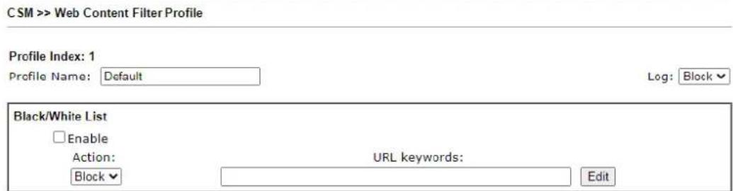
text_image
CSM >> Web Content Filter Profile Profile Index: 1 Profile Name: Default Log: Block Black/White List Enable Action: Block URL keywords: Edit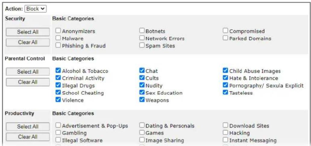
text_image
Action: Block Security Select All Clear All Basic Categories Anonymizers Malware Phishing & Fraud Botnets Network Errors Spam Sites Compromised Parked Domains Parental Control Basic Categories Select All Clear All ✓ Alcohol & Tobacco ✓ Criminal Activity ✓ Illegal Drugs ✓ School Cheating ✓ Violence ✓ Chat ✓ Cults ✓ Nudity ✓ Sex Education ✓ Weapons ✓ Child Abuse Images ✓ Hate & Intolerance ✓ Pornography/ Sexula Explicit ✓ Tasteless Productivity Basic Categories Select All Clear All ✓ Advertisement & Pop-Ups ✓ Gambling ✓ Illegal Software ✓ Dating & Personals ✓ Games ✓ Image Sharing ✓ Download Sites ✓ Hacking ✓ Instant MessagingAvailable settings are explained as follows:
| Item | Description |
| Profile Name Type a name for the CSM profile. The maximum length of the name you can set is 15 characters. | |
| Log | Pass - Only the log about Pass will be recorded in Syslog.Block - Only the log about Block will be recorded in Syslog.All - All the actions (Pass and Block) will be recorded in Syslog. |
| Black/White List | Enable - Activate white/ black list function for such profile.URL keywords - Click Edit to choose the group or object profile as the content of white/ black list. |
| Pass - allow accessing into the corresponding webpage with the characters listed on Group/Object Selections. If the web pages do not match with the specified feature set here, they will be processed with the categories listed on the box below.Block - restrict accessing into the corresponding webpage with the characters listed on Group/Object Selections.If the web pages do not match with the specified feature set here, they will be processed with the categories listed on the box below. | |
| Action | Pass - allow accessing into the corresponding webpage the categories listed on the box below.Block - restrict accessing into the corresponding webpage with the categories listed on the box below.If the web pages do not match with the specified feature set here, it will be processed with reverse action. |
After finishing all the settings, please click OK to save the configuration.
V-2-4 DNS Filter Profile
DNS Filter blocks or allows traffic to the WAN by intercepting DNS queries, and applying UCF and WCF rules to hostnames. DNS filtering is especially useful when you wish to restrict access of protocols other than HTTP, such as HTTPS. Note that a WCF license must have already been activated before WCF rules could be used.
To configure DNS Filter Profiles, select CSM >> Web Content Filter Profile from the main menu.
CSM >> DNS Filter
DNS Filter Profile Table
Set to Factory Default
| Profile | Name | Profile | Name |
| 1. | 5. | ||
| 2. | 6. | ||
| 3. | 7. | ||
| 4. | 8. |
Note:
To make DNS Filter profile effective, please go to Firewall >> Filter Setup page to create a firewall rule and select the desired profile.
DNS Filter Local Setting
| DNS Filter | Enable | |
| Web Content Filter | None | |
| URL Content Filter | None | |
| Syslog | None | |
| Black/White List | Enable | Blacklist |
| Address Type | Any Address | |
| Start IP Address | 0.0.0.0 | |
| End IP Address | 0.0.0.0 | |
| Subnet Mask | 0.0.0.0 | |
| IP Group | None | |
| or IP Group | None | |
| or IP Object | None | |
| or IP Object | None |
Administration Message (Max 255 characters)
Default Message
The requested Web page
from %SIP%
to %URL%
that is categorized with %CL%
has been blocked by %RNAME% DNS Filter.
Please contact your system administrator for further information.
Legend:
% SIP% - Source IP, %URL% - URL %CL% - Category, %RNAME% - Router Name

Available settings are explained as follows:
| Item | Description |
| DNS Filter Profile Table | DNS Filter Profiles take effect when DNS servers on the WAN are used for DNS queries. The router intercepts all outgoing DNS queries on UDP port 53 and applies WCF and UCF ruleson the domain names before passing the queries to the DNS servers. IP addresses of the domains are then blocked or allowed as per applicable WCF and UCF rules.DNS Filter Profiles can be applied by selecting from Firewall filter rules.Profile - Index number of the profile. Click to bring up the configuration page for the profile entry.Name - Name that identifies the profile. |
| Set to Factory Default Clear | all DNS Filter profile settings. |
| DNS Filter Local Setting By | setting the IP address of the DNS lookup server to the router's address, the router serves as a DNS lookup proxy server. When DNS Filter Local Setting is enabled, all DNS queries sent to the router will have WCF and UCF rules applied to the hostnames, and access to the resolved IP addresses will be allowed or blocked as configured in the rules.DNS Filter - Select to enable DNS Filter Local Setting.Web Content Filter - Select a WCF profile.URL Content Filter - Select a UCF profile.Syslog - The filtering result can be recorded according to the setting selected for Syslog.None - No log file will be created for this profile.Pass - Only passed access attempts will be recorded in Syslog.Block - Only blocked access attempts will be recorded in Syslog.Both - Both passed and blocked access attempts will be recorded in Syslog.Black/White List - Specify IP address, subnet mask, IP object, or IP group as a black list or white list for DNS packets passing through or blocked by Vigor router. |
| Administration Message The | message to be displayed in the browser when access to a website has been blocked. A custom message can be entered with HTML formatting in the text box.You can embed the following variables in the message:%SIP% - The source IP address that attempted the HTTP access.%DIP% - The destination IP address to which access was attempted.%URL% - The URL of the destination website.%CL% - The category to which the URL belongs.%RNAME% - The name of the router.Default Message - Click to reset the administration message to the factory default. |
To save changes on the page, click OK. To discard changes, click Cancel.
Application Notes
A-1 How to Create an Account for MyVigor
The website of MyVigor (a server located on http://myvigor.draytek.com) provides several useful services (such as Anti-Spam, Web Content Filter, Anti-Intrusion, and etc.) to filtering the web pages for the sake of protecting your system.
To access into MyVigor for getting more information, please create an account for MyVigor.
Create an Account via Vigor Router
- Click CSM>> Web Content Filter Profile. The following page will appear.
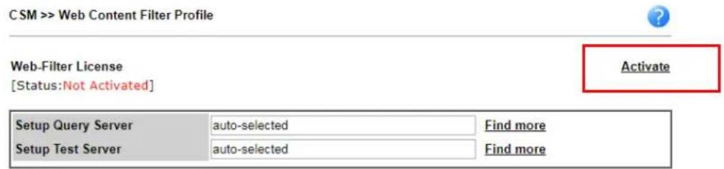
text_image
CSM >> Web Content Filter Profile Web-Filter License [Status:Not Activated] Activate Setup Query Server auto-selected Find more Setup Test Server auto-selected Find more| Web Content Filter Profile Table: Cache : L1 + L2 Cache ▼ | Set to Factory Default | | |||
| Profile | Name | Profile | Name |
| 1. | Default | 5. | |
| 2. | 6. | ||
| 3. | 7. | ||
| 4. | 8. | ||
Note:
To make Web Content Filter profile effective, please go to Firewall >> Filter Setup page to create a firewall rule and select the desired profile.

Or
Click System Maintenance>>Activation to open the following page.
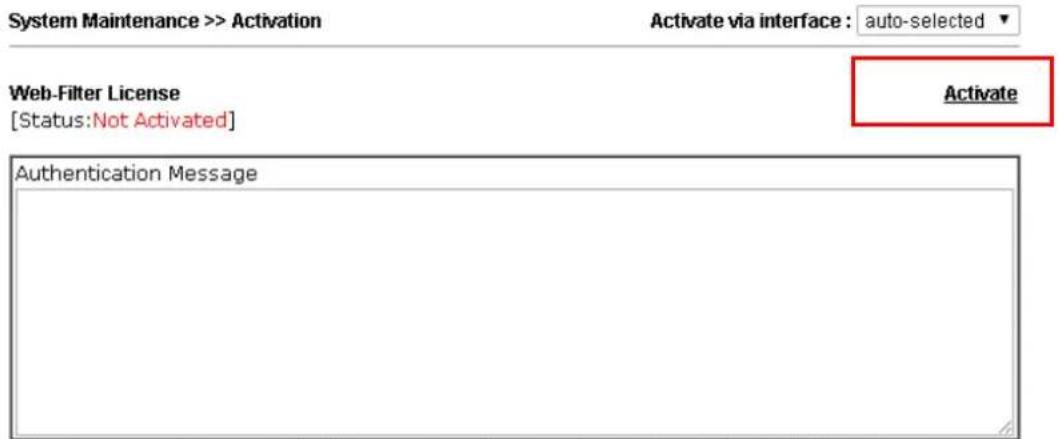
text_image
System Maintenance >> Activation Activate via interface : auto-selected ▼ Web-Filter License [Status:Not Activated] Activate Authentication MessageNote: If you want to use email alert or syslog, please configure the Sys1 on Mail Alert Setup page.
- Click the Activate link. A login page for MyVigor web site will pop up automatically.
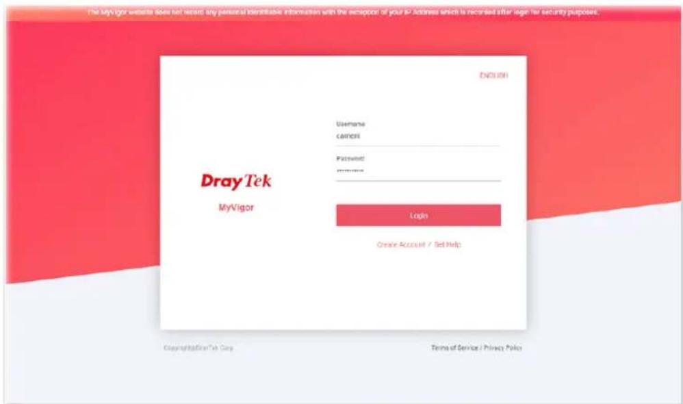
text_image
The MyVigor website does not record any personal identifiable information with the exception of your IP Address which is recorded after login for security purposes. DRay Tek MyVigor Username camers Password: ****** Login Create Account / Set Help ENGLISH Copyright@DrayTek Corp Terms of Service / Privacy Policy- Click the link of Create an account now.
- The system will ask if you are 16 years old or over.
■ If yes, click I am 16 or over.
text_image
Terms of Service / Privacy Policy Agreement DrayTek provides MyVigor (myvigor.draytek.com) service according to this agreement. When you use MyVigor service, it means that you have read, understood and agreed to accept the items listed in this agreement. DrayTek reserves the right to update the Terms of Use at any time without notice you. It is suggested for you to notice the modifications or changes at any time. If you still use MyVigor service after knowing the modifications and changes of this service, it means you have read, understood and agreed to accept the modifications and changes. If you do not agree the contents of this agreement, please stop using MyVigor service. Registration To use this service, you have to agree the following conditions: About Us DrayTek Corporation Address: No. 26, Fushing Rd., Hukou, Hsinchu Industrial Park, Hsinchu, 303, Taiwan Tel: +886 3 5972727 Fax: +886 3 5972121 Personal Data Related Issue: privacy@draytek.com Data Protection Officer: dpo@draytek.com DrayTek Corp. Version: V3.5 Date: 21 May, 2018 I am under 16 years old I am 16 or overIf not, click I am under 16 years old to get the following page. Then, click I and my legal guardian agree.
text_image
this section 8. About Us DrayTek Corporation Address: No. 26, Fushing Rd., Hukou, Hsinchu Industrial Park, Hsinchu, 303, Taiwan Tel: + 886 3 5972727 Fax: + 886 3 5972121 Personal Data Related Issue: privacy@draytek.com Data Protection Officer: dpo@draytek.com DrayTek Corp. Version: V3.5 Date: 21 May, 2018 I and my legal guardian agree Disagree- After reading the terms of service/privacy policy, click Agree.

text_image
About Us DrayTek Corporation Address: No. 26, Fushing Rd., Hukou, Hsinchu Industrial Park, Hsinchu, 303, Taiwan Tel: +886 3 5972727 Fax: +886 3 5972121 Personal Data Related Issue: privacy@draytek.com Data Protection Officer: dpo@draytek.com DrayTek Corp. Version: V3.5 Date: 21 May, 2018 Agree Disagree- In the following page, enter your personal information in this page and then click Continue.
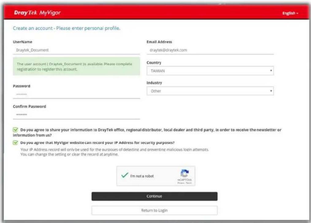
text_image
DrayTek MyVigor Create an account - Please enter personal profile. Username Draytek_Document The user account ( Draytek_Document ) is available. Please complete registration to register this account. Password ****** Confirm Password ****** Email Address draytek@draytek.com Country TAIWAN Industry Other ✓ Do you agree to share your information to DrayTek office, regional distributor, local dealer and third party, in order to receive the newsletter or information from us? ✓ Do you agree that MyVigor website can record your IP Address for security purposes? Your IP Address record will only be used for the purposes of detecting and preventing malicious login attempts. You can change the setting or clear the record at anytime. ✓ I'm not a robot mCAPTORA Private: Tenter Continue Return to Login- Choose proper selection for your computer and click Continue.
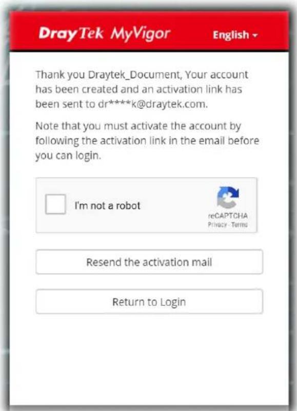
text_image
DrayTek MyVigor English Thank you Draytek_Document, Your account has been created and an activation link has been sent to dr****k@draytek.com. Note that you must activate the account by following the activation link in the email before you can login. I'm not a robot reCAPTCHA Privacy Terms Resend the activation mail Return to Login- Now you have created an account successfully.
- Check to see the confirmation email with the title of New Account Confirmation Letter from myvigor.draytek.com.
***** This is an automated message from myvigor.draytek.com. *****
Thank you (Mary) for creating an account.
Please click on the activation link below to activate your account
Link : Activate my Account
- Click the Activate my Account link to enable the account that you created. The following screen will be shown to verify the register process is finished. Please click Login.
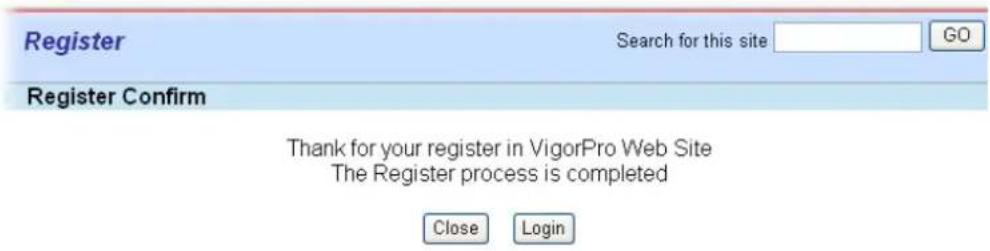
text_image
Register Search for this site GO Register Confirm Thank for your register in VigorPro Web Site The Register process is completed Close Login- When you see the following page, please type in the account and password (that you just created) in the fields of UserName and Password.
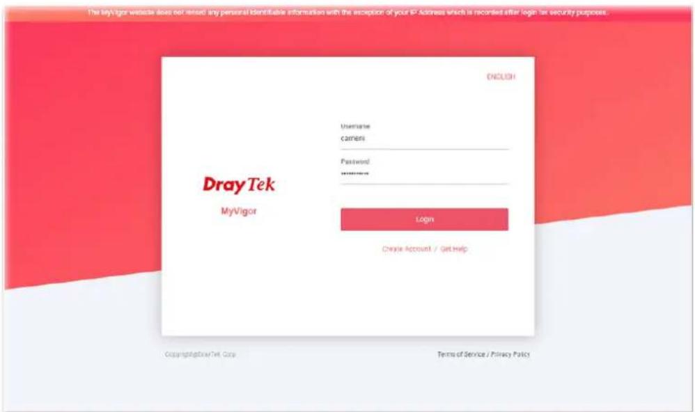
text_image
The key login website does not reuse any personal identifiable information with the exception of your IP Address which is recorded after login at security purposes. DRay Tek MyVigor UNIVERSARY CAMERA Password: ****** Login Create Account / Get Help ENGLISH Copyright@DrayTek, Copy Terms of Service / Privacy Policy- Now, click Login. Your account has been activated. You can access into MyVigor server to activate the service (e.g., WCF) that you want.
A-2 How to Block Facebook Service Accessed by the Users via Web Content Filter / URL Content Filter
There are two ways to block the facebook service, Web Content Filter and URL Content Filter.
Web Content Filter,
Benefits: Easily and quickly implement the category/website that you want to block.
Note: License is required.
URL Content Filter,
Benefits: Free, flexible for customize webpage.
Note: Manual setting (e.g., one keyword for one website.)
I. Via Web Content Filter
- Make sure the Web Content Filter (powered by Commtouch) license is valid.
CSM >> Web Content Filter Profile

text_image
Web-Filter License [Status: Commtouch] [Start Date:2012-12-31 Expire Date:2013-01-08] Setup Query Server auto-selected Find more Setup Test Server auto-selected Find more Activate| Web Content Filter Profile Table: | Set to Factory Default | ||
| Profile | Name | Profile | Name |
| 1. | Default | 5. | |
| 2. | 6. | ||
| 3. | 7. | ||
| 4. | 8. | ||

text_image
The requested Web page
from %SIP%
to %URL%
that is categorized with %CL%
has been blocked by %RNAME% Web Content Filter.
Please contact your system administrator for further information.
- Open CSM >> Web Content Filter Profile to create a WCF profile. Check Social Networking with Action, Block.
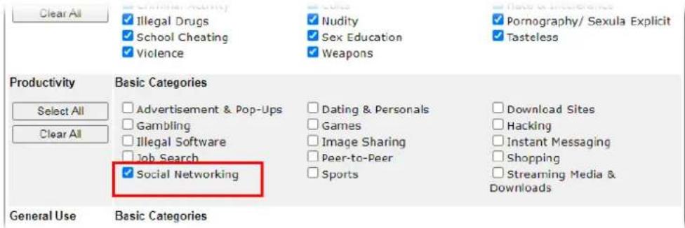
text_image
Clear All ✓ Illegal Drugs ✓ School Cheating ✓ Violence ✓ Nudity ✓ Sex Education ✓ Weapons ✓ Pornography/ Sexula Explicit ✓ Tasteless Productivity Select All Clear All Basic Categories ✓ Advertisement & Pop-Ups ✓ Gambling ✓ Illegal Software ✓ Job Search ✓ Social Networking ✓ Dating & Personals ✓ Games ✓ Image Sharing ✓ Peer-to-Peer ✓ Sports ✓ Download Sites ✓ Hacking ✓ Instant Messaging ✓ Shopping ✓ Streaming Media & Downloads General Use Basic Categories- Enable this profile in Firewall>>General Setup>>Default Rule.
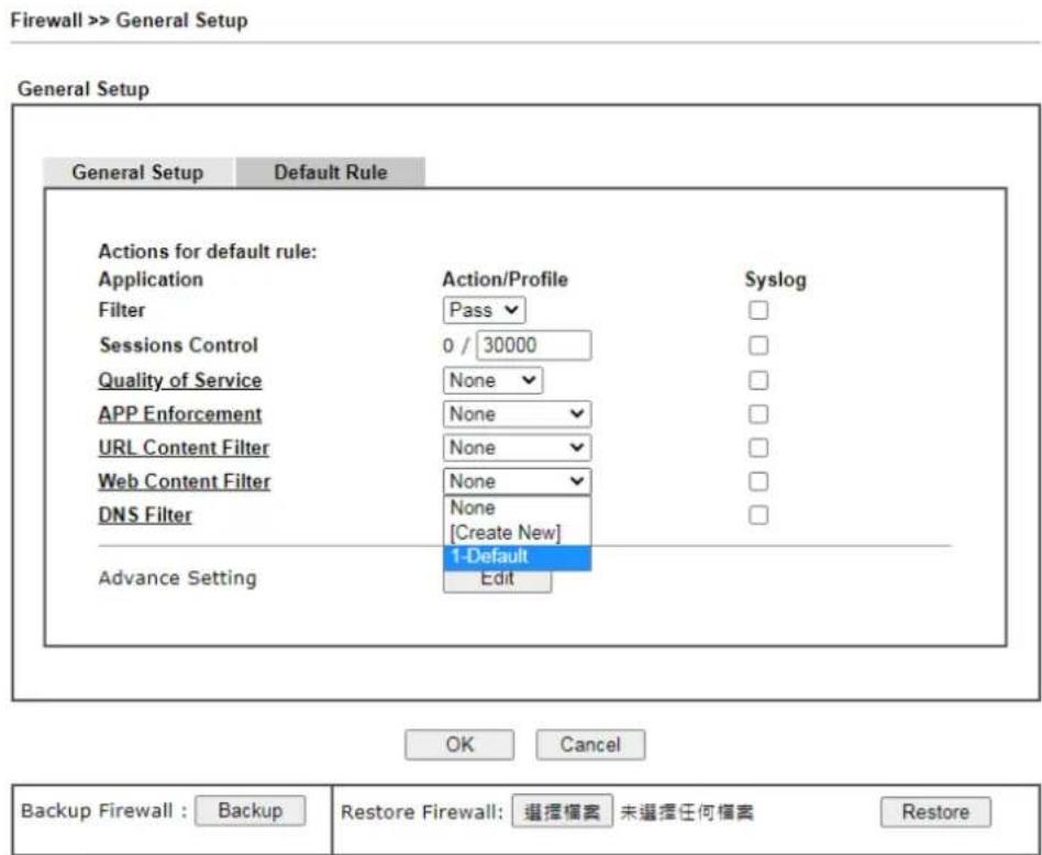
text_image
Firewall >> General Setup General Setup General Setup Default Rule Actions for default rule: Application Action/Profile Syslog Filter Pass Sessions Control 0 / 30000 Quality of Service None APP Enforcement None URL Content Filter None Web Content Filter None DNS Filter None [Create New] Advance Setting 1-Default Edit OK Cancel Backup Firewall : Backup Restore Firewall: 选择檔案 未選擇任何檔案 RestoreNote: This will not backup the detail setting of Quality of Service and Schedule.
- Next time when someone accesses facebook via this router, the web page would be blocked and the following message would be displayed instead.
The requested Web page from 192.168.2.114 to www.facebook.com/ that is categorized with [Social Networking] has been blocked by Web Content Filter.
Please contact your system administrator for further information.
[Powered by DrayTek]
II. Via URL Content Filter
A. Block the web page containing the word of "Facebook"
- Open Object Settings>>Keyword Object. Click an index number to open the setting page.
- In the field of Contents, please type facebook. Configure the settings as the following figure.
Objects Setting >> Keyword Object Setup
Profile Index : 1
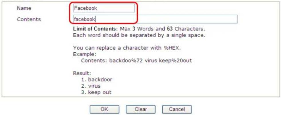
text_image
Name Facebook Contents facebook Limit of Contents: Max 3 Words and 63 Characters. Each word should be separated by a single space. You can replace a character with %HEX. Example: Contents: backdoo%72 virus keep%20out Result: 1. backdoor 2. virus 3. keep out OK Clear Cancel- Open CSM>>URL Content Filter Profile. Click an index number to open the setting page.
- Configure the settings as the following figure.
CSM >> URL Content Filter Profile
Profile Index: 1
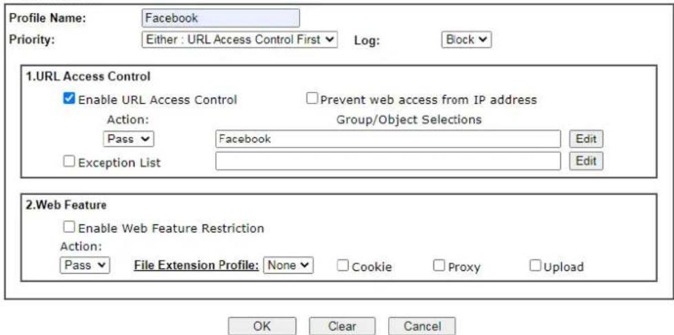
text_image
Profile Name: Facebook Priority: Either : URL Access Control First Log: Block 1.URL Access Control Enable URL Access Control Prevent web access from IP address Action: Group/Object Selections Pass ✓ Facebook Edit Exception List Edit 2.Web Feature Enable Web Feature Restriction Action: Pass ✓ File Extension Profile: None ✓ Cookie Proxy Upload OK Clear Cancel-
When you finished the above steps, click OK. Then, open Firewall>>General Setup.
-
Click the Default Rule tab. Choose the profile just configured from the drop down list in the field of URL Content Filter. Now, users cannot open any web page with the word "facebook" inside.
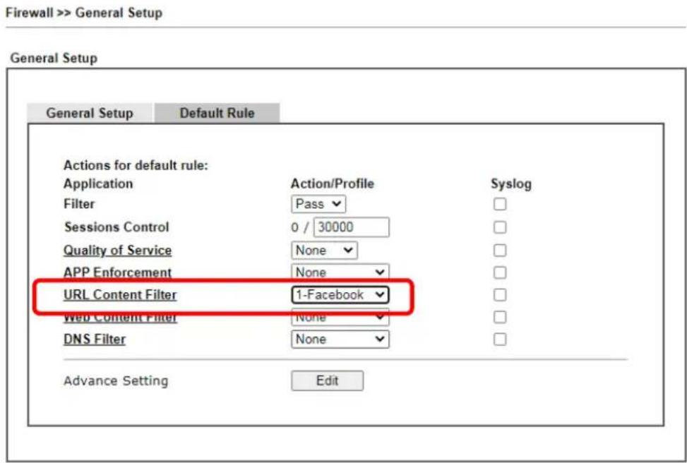
text_image
Firewall >> General Setup General Setup General Setup Default Rule Actions for default rule: Application Action/Profile Syslog Filter Pass Sessions Control 0 / 30000 Quality of Service None APP Enforcement None URL Content Filter 1-Facebook Web Content Filter None DNS Filter None Advance Setting EditB. Disallow users to play games on Facebook
- Open Object Settings>>Keyword Object. Click an index number to open the setting page.
- In the field of Contents, please type apps.facebook. Configure the settings as the following figure.
Objects Setting >> Keyword Object Setup
Profile Index : 2
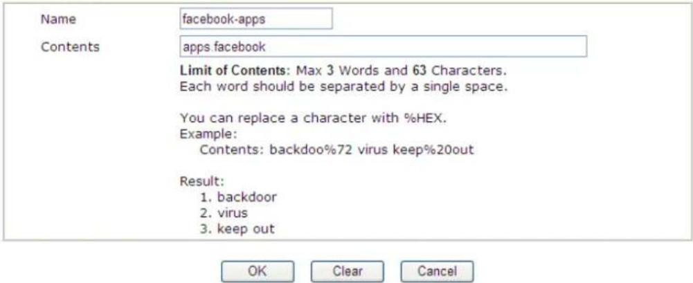
text_image
Name facebook-apps Contents apps facebook Limit of Contents: Max 3 Words and 63 Characters. Each word should be separated by a single space. You can replace a character with %HEX. Example: Contents: backdoo%72 virus keep%20out Result: 1. backdoor 2. virus 3. keep out OK Clear Cancel- Open CSM>>URL Content Filter Profile. Click an index number to open the setting page.
- Configure the settings as the following figure.
CSM >> URL Content Filter Profile
Profile Index: 2
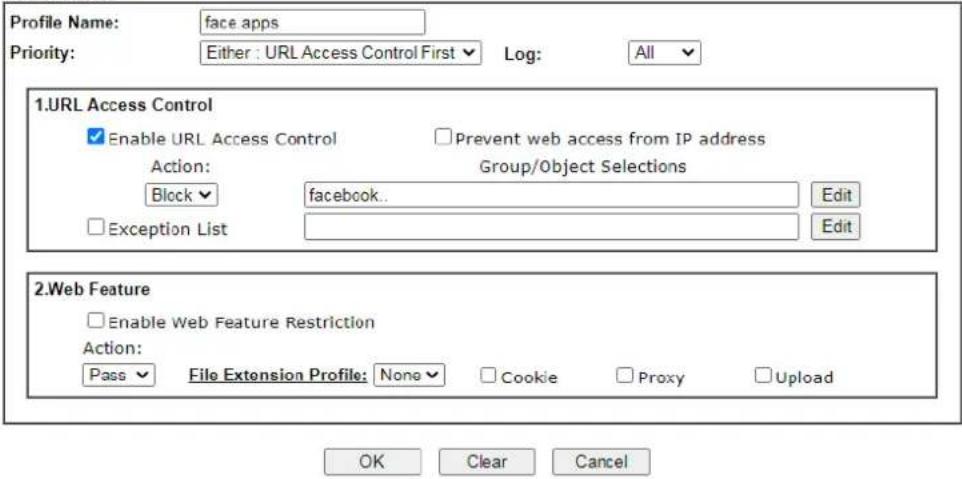
text_image
Profile Name: face apps Priority: Either : URL Access Control First Log: All 1.URL Access Control Enable URL Access Control Prevent web access from IP address Action: Group/Object Selections Block facebook.. Edit Exception List Edit 2.Web Feature Enable Web Feature Restriction Action: Pass File Extension Profile: None Cookie Proxy Upload OK Clear Cancel- When you finished the above steps, please open Firewall>>General Setup.
- Click the Default Rule tab. Choose the profile just configured from the drop down list in the field of URL Content Filter. Now, users cannot open any web page with the word "facebook" inside.
Firewall >> General Setup
General Setup
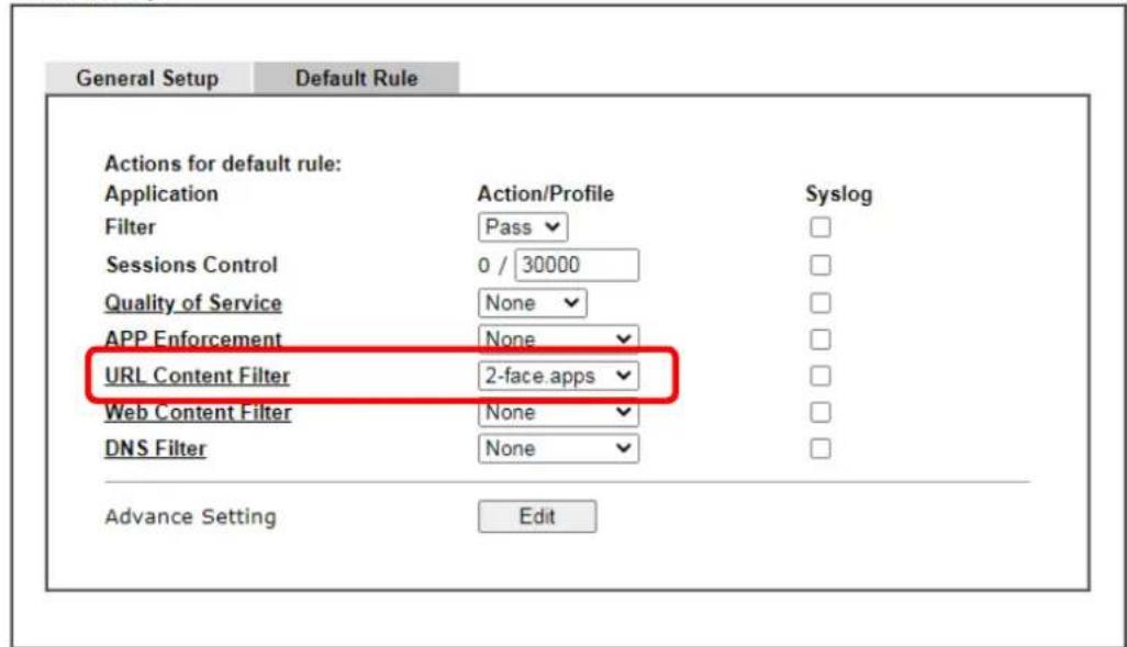
text_image
General Setup Default Rule Actions for default rule: Application Action/Profile Syslog Filter Pass Sessions Control 0 / 30000 Quality of Service None APP Enforcement None URL Content Filter 2-face.apps Web Content Filter None DNS Filter None Advance Setting EditThis page is left blank.
Part VI Management

System Maintenance
There are several items offered for the Vigor router system setup: System Status, TR-069, Administrator Password, User Password, Configuration Backup, Syslog / Mail Alert, Time and Date, SNMP, Management, Panel Control, Self-Signed Certificate, Reboot System, Firmware Upgrade, and Activation.

Bandwidth Management
It is used to control the bandwidth of data transmission through configuration of Sessions Limit, Bandwidth Limit, and Quality of Servie (QoS).
VI-1 System Maintenance
For the system setup, there are several items that you have to know the way of configuration: System Status, TR-069, Administrator Password, User Password, Configuration Backup, Syslog / Mail Alert, Time and Date, SNMP, Management, Panel Control, Self-Signed Certificate, Reboot System, Firmware Upgrade and Activation.
Below shows the menu items for System Maintenance.
035174
System Maintenance
System Status
TR-069
Administrator Password
User Password
Configuration Backup
SysLog / Mail Alert
Time and Date
SNMP
Management
Panel Control
Self-Signed Certificate
Reboot System
Firmware Upgrade
Activation
V
Web User Interface
VI-1-1 System Status
The System Status provides basic network settings of Vigor router. It includes LAN and WAN interface information. Also, you could get the current running firmware version or firmware related information from this presentation.
System Status
| Model Name | : VigorLTE200n |
| Firmware Version | : 3.9.8.2 |
| Build Date/Time | : Aug 18 2022 23:45:50 |
| LAN | |||||
| MAC Address | IP Address | Subnet Mask | DHCP Server | DNS | |
| LAN1 | 00-1D-AA-94-F7-E4 | 192.168.1.60 | 255.255.255.0 | ON | 8.8.8.8 |
| LAN2 | 00-1D-AA-94-F7-E4 | 192.168.2.1 | 255.255.255.0 | ON | 8.8.8.8 |
| IP Routed Subnet | 00-1D-AA-94-F7-E4 | 192.168.0.1 | 255.255.255.0 | ON | 8.8.8.8 |
| Wireless LAN | |||
| MAC Address00-1D-AA-94-F7-E4 | Frequency DomainEurope | Firmware Version4.0.1.0rev2.P1 | SSIDDrayTek |
| WAN | |||||
| Link Status | MAC Address | Connection | IP Address | Default Gateway | |
| WAN2 | Disconnected | 00-1D-AA-94-F7-E6 | --- | --- | --- |
| LTE | Disconnected | 00-1E-10-1F-AB-D2 | --- | --- | --- |
| IPv6 | |||
| Address | Scope | Internet Access Mode | |
| LAN | FE80::21D:AAFF:FE94:F7E4/64 | Link | --- |
User Mode is OFF now.
Available settings are explained as follows:
| Item | Description |
| Model Name Display the model name of the router. | |
| Firmware Version | Display the firmware version of the router. |
| Build Date/Time Display the date and time of the current firmware build. | |
| LAN | MAC Address- Display the MAC address of the LAN Interface.IP Address- Display the IP address of the LAN interface.Subnet Mask- Display the subnet mask address of the LAN interface.DHCP Server- Display the current status of DHCP server of the LAN interface.DNS- Display the assigned IP address of the primary DNS. |
| WAN | Link Status- Display current connection status. |
| MAC Address- Display the MAC address of the WAN Interface.Connection- Display the connection type.IP Address- Display the IP address of the WAN interface.Default Gateway- Display the assigned IP address of the default gateway. | |
| IPv6 | Address - Display the IPvScope - Display the scope of IPv6 address. For example, IPv6 Link Local could only be used for direct IPv6 link. It can't be used for IPv6 internet.Internet Access Mode - Display the connection mode chosen for accessing into Internet. |
VI-1-2 TR-069
This device supports TR-069 standard. It is very convenient for an administrator to manage a TR-069 device through an Auto Configuration Server, e.g., VigorACS.
System Maintenance >> TR-069 Setting
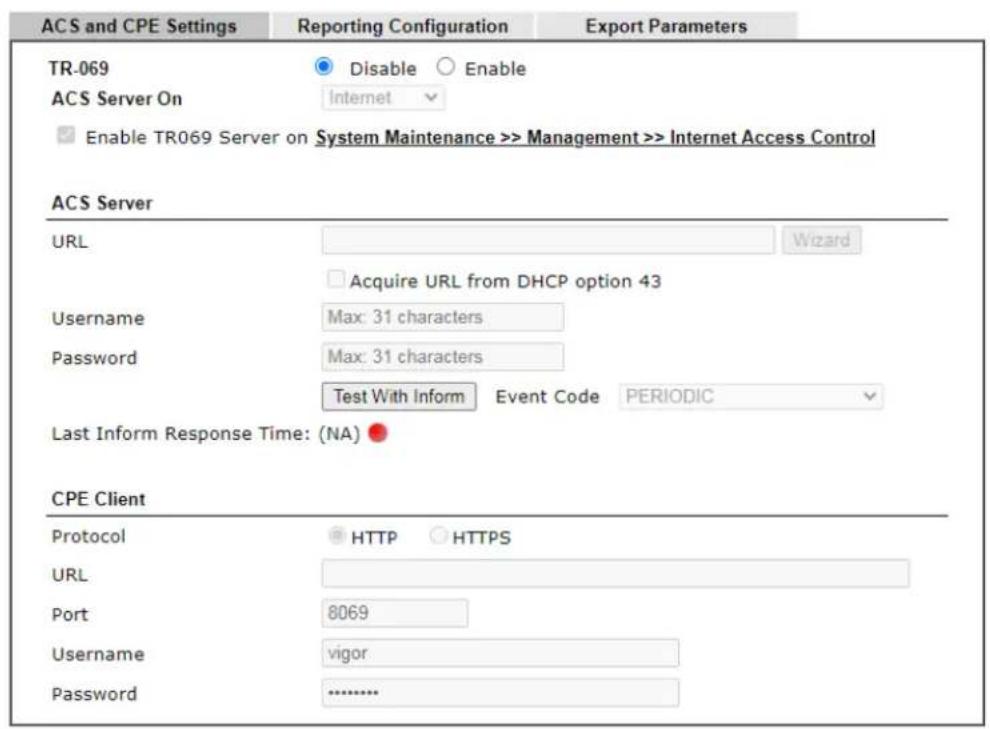
text_image
ACS and CPE Settings Reporting Configuration Export Parameters TR-069 Disable Enable ACS Server On Internet Enable TR069 Server on System Maintenance >> Management >> Internet Access Control ACS Server URL Acquire URL from DHCP option 43 Username Max: 31 characters Password Max: 31 characters Test With Inform Event Code PERIODIC Last Inform Response Time: (NA) CPE Client Protocol HTTP HTTPS URL Port 8069 Username vigor Password ............Periodic Inform Settings

text_image
Enable Disable Time Interval 900 second(s)STUN Settings
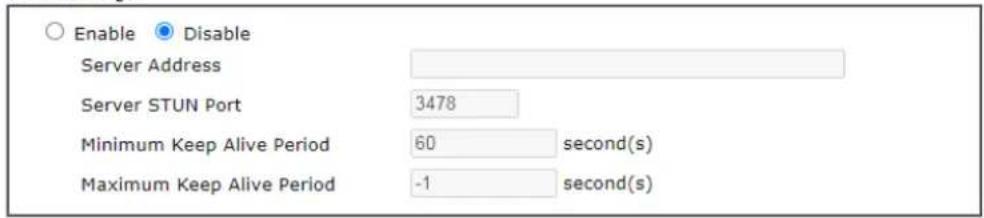
text_image
Enable Disable Server Address Server STUN Port 3478 Minimum Keep Alive Period 60 second(s) Maximum Keep Alive Period -1 second(s)Apply Settings to APs

text_image
Enable Disable AP Password Specify STUN Settings for APs OK ClearAvailable settings are explained as follows:
| Item | Description |
| TR-069 | Click Enable to activate the settings on this page. |
| ACS Server On | Choose the interface for the router connecting to ACS server. |
| Enable TR069 Server on ... | Enable TR069 Server on SystemMaintenance>>Management>>Internet Access Control - If enable, a user will be allowed to access into TR-069 from WAN. |
| ACS Server | URL/Username/Password - Such data must be typed according to the ACS (Auto Configuration Server) you want to link. Please refer to Auto Configuration Server user's manual for detailed information.Wizard - Click it to enter the IP address of VigorACS server, port number and the handler.Test With Inform - Click it to send a message based on the event code selection to test if such CPE is able to communicate with VigorACS SI server.Event Code - Use the drop down menu to specify an event to perform the test.Last Inform Response Time - Display the time that VigorACS server made a response while receiving Inform message from CPE last time. |
| CPE Client | Such information is useful for Auto Configuration Server.Enable/Disable - Allow/ Deny the CPE Client to connect with Auto Configuration Server.Port - Sometimes, port conflict might be occurred. To solve such problem, you might change port number for CPE.Usage and Password - Enter the username and password that VigorACS can use to access into such CPE. |
| Periodic Inform Settings | The default setting is Enable. Please set interval time or schedule time for the router to send notification to CPE. Or click Disable to close the mechanism of notification. |
| STUN Settings | The default is Disable. If you click Enable, please Enter the relational settings listed below:Server Address - Enter the IP address of the STUN server.Server Port - Enter the port number of the STUN server.Minimum Keep Alive Period - If STUN is enabled, the CPE must send binding request to the server for the purpose of maintaining the binding in the Gateway. Please type a number as the minimum period. The default setting is “60 seconds”.Maximum Keep Alive Period - If STUN is enabled, the CPE must send binding request to the server for the purpose of maintaining the binding in the Gateway. Please type a number as the maximum period. A value of “-1” indicates that no maximum period is specified. |
| Apply Settings to APs This feature is able to apply TR-069 settings (including STUN and ACS server settings) to all of APs managed by VigorLTE 200 at the same time.Disable - Related settings will not be applied to VigorAP.Enable - Above STUN settings will be applied to VigorAP after clicking OK. If such feature is enabled, you have to Enter the password for accessing VigorAP.AP Password - Enter the password of the VigorAP that you want to apply VigorLTE 200's TR-069 settings.Specific STUN Settings to APs - After clicking the Enable | |
| radio button forApply Settings to APs, if you want to apply specific STUN settings (not the STUN Settings configured for VigorLTE 200) to VigorAPs to meet specific requirements, simply check this box. Then, Enter the server IP address, server port, minimum keep alive period and maximum keep alive period respectively. | |
After finishing all the settings here, please click OK to save the configuration.
VI-1-3 Administrator Password
This page allows you to set new password.
System Maintenance >> Administrator Password Setup
Administrator Password
| Old Password | Max: 23 characters | |
| New Password | (Max. 23 characters allowed) | |
| Confirm Password | (Max. 23 characters allowed) |
Note:
Password can contain only a-z A-Z 0-9, ; :." <> * + = | ? @ # ^ ! ( )
OK
Available settings are explained as follows:
| Item | Description |
| Administrator Password Old | Password - Enter the old password. The factory default setting for password is “admin”.New Password -Enter new password in this field. The length of the password is limited to 23 characters.Confirm Password -Enter the new password again. |
When you click OK, the login window will appear. Please use the new password to access into the web user interface again.
VI-1-4 User Password
This page allows you to set new password for user operation.
System Maintenance >> User Password
√ Enable User Mode for simple web configuration
User Password

text_image
Password ...... Confirm Password ...... Password Strength: Weak Medium Strong Strong password requirements: 1. Have at least one upper-case letter and one lower-case letter. 2. Including non-alphanumeric characters is a plus.Note:
- Password can contain a-z A-Z 0-9, ; :." < > * + = | ? @ # ^ ! ( )
- Password can't be all asterisks("). For example, '*' or '*****' is illegal, but '123**' or '*'45' is OK.
OK
Available settings are explained as follows:
| Item | Description |
| Enable User Mode for simple web configuration | After checking this box, you can access into the web user interface with the password typed here for simple web configuration.The settings on simple web user interface will be different with full web user interface accessed by using the administrator password. |
| Password Enter new password | in this field. The length of the password is limited to 31 characters. |
| Confirm Password Enter the new password again. | |
| Password Strength Display the security strength of the password specified above. | |
| Set to Factory Default Click to return to the factory default setting. | |
When you click OK, the login window will appear. Please use the new password to access into the web user interface again. Below shows an example for accessing into User Operation with User Password.
- Open System Maintenance>>User Password.
- Check the box of Enable User Mode for simple web configuration to enable user mode operation. Type a new password in the field of New Password and click OK.
System Maintenance >> User Password
√ Enable User Mode for simple web configuration
User Password

text_image
Password ...... Confirm Password ...... Password Strength: Weak Medium Strang Strong password requirements: 1. Have at least one upper-case letter and one lower-case letter. 2. Including non-alphanumeric characters is a plus.- The following screen will appear. Simply click OK.
System Maintenance >> User Password
Active Configuration
Password

- Log out Vigor router web user interface by clicking the Logout button.

text_image
Logout- The following window will be open to ask for username and password. Enter the new user password in the filed of Password and click Login.
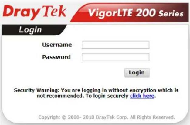
text_image
DrayTek VigorLTE 200 Series Login Username Password Login Security Warning: You are logging in without encryption which is not recommended. To login securely click here. Copyright © 2000- 2018 DrayTek Corp. All Rights Reserved.- The main screen with User Mode will be shown on the web page.
Settings to be configured in User Mode will be less than settings in Admin Mode. Only basic configuration settings will be available in User Mode.

Info
Setting in User Mode can be configured as same as in Admin Mode.
VI-1-5 Configuration Backup
Such function can be used to apply the router settings configured by other Vigor router to VigorLTE 200.
Backup the Configuration
Follow the steps below to backup your configuration.
- Go to System Maintenance >> Configuration Backup. The following page will be popped-up, as shown below.
System Maintenance >> Configuration Backup
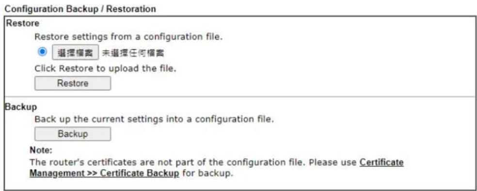
text_image
Configuration Backup / Restoration Restore Restore settings from a configuration file. ● 选择档案 未选择任何档案 Click Restore to upload the file. Restore Backup Back up the current settings into a configuration file. Backup Note: The router's certificates are not part of the configuration file. Please use Certificate Management >> Certificate Backup for backup.Available settings are explained as follows:
| Item | Description |
| Restore | Choose File - Click it to specify a file to be restored.Restore - Restore the configuration. If the file is encrypted, the system will ask you to Enter the password to decrypt the configuration file. |
| Backup Click it to perform the configuration backup of this router. | |
- Click Backup button to get into the following dialog. Click Save button to open another dialog for saving configuration as a file.
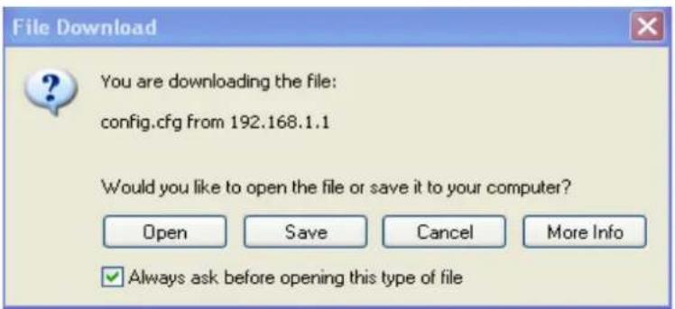
text_image
File Download You are downloading the file: config.cfg from 192.168.1.1 Would you like to open the file or save it to your computer? Open Save Cancel More Info ✓ Always ask before opening this type of file- In Save As dialog, the default filename is config.cfg. You could give it another name by yourself.
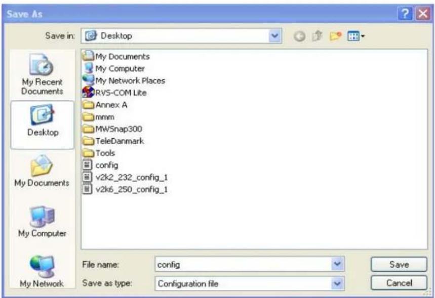
text_image
Save As Save in: Desktop My Documents My Computer My Network Places RVS-COM Lite Annex A mmm MWSnap300 TeleDanmark Tools config v2k2_232_config_1 v2k6_250_config_1 File name: config Save as type: Configuration file My Recent Documents Desktop My Documents My Computer My Network- Click Save button, the configuration will download automatically to your computer as a file named config.cfg.
The above example is using Windows platform for demonstrating examples. The Mac or Linux platform will appear different windows, but the backup function is still available.

Info
Backup for Certification must be done independently. The Configuration Backup does not include information of Certificate.
Restore Configuration
- Go to System Maintenance >> Configuration Backup. The following windows will be popped-up, as shown below.
System Maintenance >> Configuration Backup
Configuration Backup / Restoration
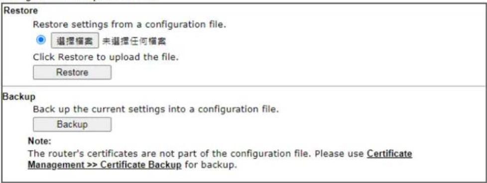
text_image
Restore Restore settings from a configuration file. ● 选择档案 未选择任何档案 Click Restore to upload the file. Restore Backup Back up the current settings into a configuration file. Backup Note: The router's certificates are not part of the configuration file. Please use Certificate Management >> Certificate Backup for backup.- Click Choose File button to choose the correct configuration file for uploading to the router.
- Click Restore button and wait for few seconds, the following picture will tell you that the restoration procedure is successful.
VI-1-6 Syslog/Mail Alert
SysLog function is provided for users to monitor router.
System Maintenance >> SysLog / Mail Alert Setup
SysLog / Mail Alert Setup
| SysLog Access Setup □Enable Syslog Save to: ■Syslog Server Router Name DrayTek Server IP/Hostname Destination Port 514 Enable syslog message: ■Firewall Log ■VPN Log ■User Access Log ■WAN Log ■Router/DSL information ■WLAN Log | Mail Alert Setup □Enable Send a test e-mail SMTP Server SMTP Port 25 Mail To Sender Address □Use SSL □Authentication Username Password Enable E-Mail Alert: ■DoS Attack ■APPE ■VPN LOG □Debug Log |
OK Clear
Available settings are explained as follows:
| Item | Description |
| SysLog Access Setup | Enable - Check Enable to activate function of syslog.Syslog Save to - Check Syslog Server to save the log to Syslog server. |
| Router Name | Display the name for such router configured in System Maintenance>>Management.If there is no name here, simply lick the link to access into System Maintenance>>Management to set the router name.Server IP /Hostname -The IP address of the Syslog server.Destination Port - Assign a port for the Syslog protocol.Enable syslog message - Check the box listed on this web page to send the corresponding message of firewall, VPN, User Access, WAN, Router/ DSL information and WLAN to Syslog. |
| Mail Alert Setup | Check Enable to activate function of mail alert.Send a test e-mail - Make a simple test for the e-mail address specified in this page. Please assign the mail address first and click this button to execute a test for verify the mail address is available or not.SMTP Server/SMTP Port - The IP address/ Port number of the SMTP server.Mail To - Assign a mail address for sending mails out.Sender Address - Assign a path for receiving the mail from outside.Use SSL - Check this box to use port 465 for SMTP server forsome e-mail server uses https as the transmission method. Authentication - Check this box to activate this function while using e-mail application.User Name - Enter the user name for authentication.Password - Enter the password for authentication.Enable E-mail Alert - Check the box to send alert message to the e-mail box while the router detecting the item(s) you specify here. |
Click OK to save these settings.
For viewing the Syslog, please do the following:
-
Just set your monitor PC's IP address in the field of Server IP Address
-
Install the Router Tools in the Utility within provided CD. After installation, click on the Router Tools>>Syslog from program menu.
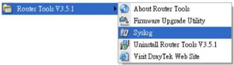
text_image
Router Tools V3.5.1 About Router Tools Firmware Upgrade Utility Syslog Uninstall Router Tools V3.5.1 Visit DrayTek Web Site- From the Syslog screen, select the router you want to monitor. Be reminded that in Network Information, select the network adapter used to connect to the router. Otherwise, you won't succeed in retrieving information from the router.

text_image
DrayTek Syslog 4.5.3 Syslog Utility 172.16.3.130 WAN Information TX Rate RX Rate Log Filter Keyword Apply to: Firevol Misc Tool Setup Telnet Read-out Setup Codopass Information Recovery Network Information NetState Host Name carrie-0c7cb251 NIC Description Athorcs AR8121/AR8113/AR8114 PCI-E Ethernet Controller - Packet Schedul NIC Information NAC Address E0-CB-4E DA-40-79 IP Address 192.168.1.10 Subnet Mask 255.255.255.0 DNS Servers 8.8.4.4 8.8.6.8 Default Getaway 192.168.1.5 DHCP Server 192.168.1.5 Lease Obtained Tue Aug 27 00:04:10 2013 Lease Expires Fri Aug 30 00:04:10 2013 On Line Routers IP Address Mask MAC 192.168.1.5 255.255.25... 00-50-7F-CD-0... Refresh OK CancelVI-1-7 Time and Date
It allows you to specify where the time of the router should be inquired from.
System Maintenance >> Time and Date
Time Information

text_image
Current System Time 2000 Jan 2 Sun 5 : 35 : 35 Inquire TimeTime Setup
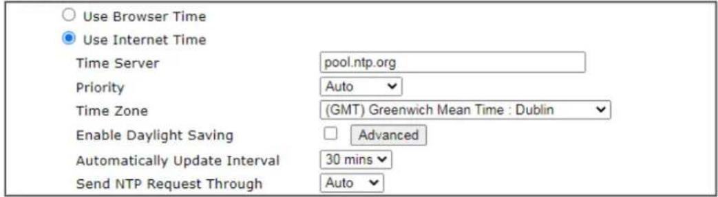
text_image
Use Browser Time Use Internet Time Time Server pool.ntp.org Priority Auto Time Zone (GMT) Greenwich Mean Time : Dublin Enable Daylight Saving □ Advanced Automatically Update Interval 30 mins Send NTP Request Through Auto
Available settings are explained as follows:
| Item | Description |
| Current System Time | ClickInquire Timeto get the current time. |
| Use Browser TimeSelect this option to use the browser time from the remote administrator PC host as router's system time. | |
| Use Internet TimeSelect to inquire time information from Time Server on the Internet using assigned protocol. | |
| Time ServerEnter the website of the time server. | |
| Priority | ChooseAutoorIPv6Firstas the priority. |
| Time ZoneSelect the time zone where the router is located. | |
| Enable Daylight Saving Check the box to enable the daylight saving. Such feature is available for certain area.Advanced- Click it to open a pop up dialog.Daylight Saving AdvancedDefaultStart: Last Sunday in MarchEnd: Last Sunday in OctoberCustomized: By DateStart: Month Day 00:00End: Month Day 00:00Customized: By WeekdayStart: January First Sunday 00:00End: January First Sunday 00:00OK CloseUse the default time setting or set user defined time for your requirement. | |
| Automatically Update Interval | Select a time interval for updating from the NTP server. |
| Send NTP Request Through | Specify a WAN interface to send NTP request for time synchronization. |
Click OK to save these settings.
VI-1-8 SNMP
This page allows you to configure settings for SNMP and SNMPV3 services.
The SNMPv3 is more secure than SNMP through the encryption method (support AES and DES) and authentication method (support MD5 and SHA) for the management needs.
System Maintenance >> SNMP
SNMP Setup
Enable SNMP Agent
Enable SNMPV1 Agent
Enable SNMPV2C Agent
Get Community
Set Community
Manager Host IP(IPv4)
public
private
IP
Subnet Mask
1
2
3
|
F
□
□
□
□
□
[Non-Text]
-
|
|
|
|
|
public
public
IP
IP
|
|
□
□
□
□
□
[Non-Text]
[Non-Text]
[Non-Text]
[Non-Text]
[Non-Text]
[Non-Text]
[Non-Text]
[Non-Text]
[Non-Text]
[Non-Text]
[Non-Text]
[Non-Text]
[Non-Text]
[Non-Text]
[Non-Text]
[Non-Text]
[Non-Text]
| Please Enter IPv4 address to specify certain host. | |
| Manager Host IP (IPv6) | Set one host as the manager to execute SNMP function.Please Enter IPv6 address to specify certain host. |
| Trap Community | Set trap community by typing a proper name. The default setting is public.The maximum length of the text is limited to 23 characters. |
| Notification Host IP (IPv4) | Set the IPv4 address of the host that will receive the trap community. |
| Notification Host IP (IPv6) | Set the IPv6 address of the host that will receive the trap community. |
| Trap Timeout The default setting is 10 seconds. | |
| Enable SNMPV3 Agent Check to enable SNMPV3 function.USM User - USM means user-based security mode.Enter the username to be used for authentication. The maximum allowed length is 23 characters.Auth Algorithm - Choose one of the hashing methods to be used with the authentication algorithm.Auth Password - Enter a password for authentication. The maximum allowed length is 23 characters.Privacy Algorithm - Choose an encryption method as the privacy algorithm.Privacy Password - Enter a password for privacy. The maximum allowed length is 23 characters. | |
Click OK to save these settings.
VI-1-9 Management
This page allows you to manage the settings for Internet/ LAN Access Control, Access List from Internet, Management Port Setup, TLS/ SSL Encryption Setup, CVM Access Control and Device Management.
The management pages for IPv4 and IPv6 protocols are different.
For IPv4
System Maintenance >> Management

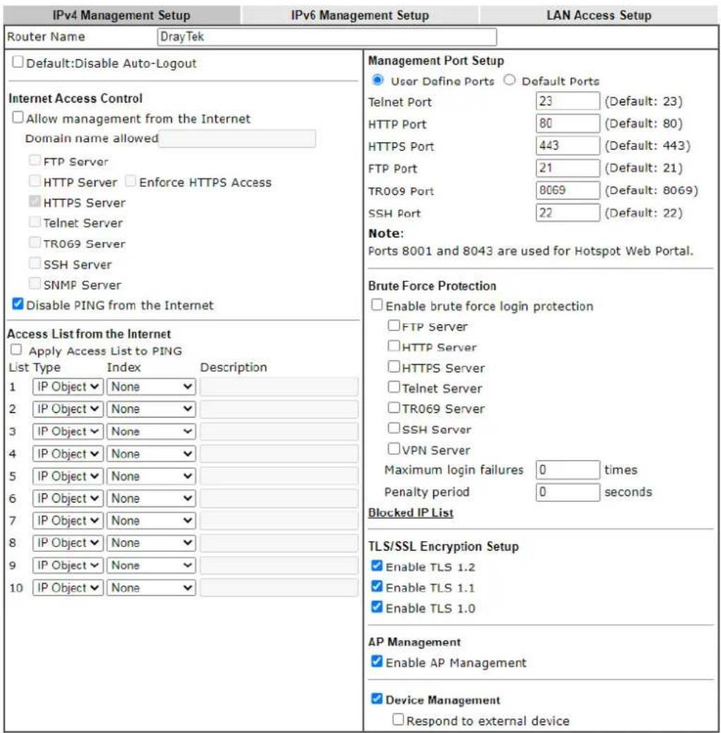
text_image
IPv4 Management Setup IPv6 Management Setup LAN Access Setup Router Name DrayTek Default:Disable Auto-Logout Internet Access Control Allow management from the Internet Domain name allowed FTP Server HTTP Server Enforce HTTPS Access HTTPS Server Telnet Server TR069 Server SSH Server SNMP Server Disable PING from the Internet Access List from the Internet Apply Access List to PING List Type Index Description 1 IP Object None 2 IP Object None 3 IP Object None 4 IP Object None 5 IP Object None 6 IP Object None 7 IP Object None 8 IP Object None 9 IP Object None 10 IP Object None Management Port Setup User Define Ports Default Ports Telnet Port 23 (Default: 23) HTTP Port 80 (Default: 80) HTTPS Port 443 (Default: 443) FTP Port 21 (Default: 21) TR069 Port 8069 (Default: 8069) SSH Port 22 (Default: 22) Note: Ports 8001 and 8043 are used for Hotspot Web Portal. Brute Force Protection Enable brute force login protection FTP Server HTTP Server HTTPS Server Telnet Server TR069 Server SSH Server VPN Server Maximum login failures 0 times Penalty period 0 seconds Blocked IP List TLS/SSL Encryption Setup Enable TLS 1.2 Enable TLS 1.1 Enable TLS 1.0 AP Management Enable AP Management Device Management Respond to external deviceOK
Available settings are explained as follows:
| Item | Description |
| Router Name Enter the router name provided by ISP. | |
| Default: Disable Auto-Logout | If it is enabled, the function of auto-logout for web user interface will be disabled. The web user interface will be open until you click the Logout icon manually. The web user interface will be open until you click the Logout icon manually. |
| Internet Access Control Allow management from the Internet - Enable the checkbox to allow system administrators to login from the Internet. There are several servers provided by the system to allow you managing the router from Internet. Check the box(es) to specify.Disable PING from the Internet - Check the checkbox to reject all PING packets from the Internet. For security issue, this function is enabled by default. | |
| Access List from the Internet | The ability of system administrators to log into the router can be restricted to up to 10 specific hosts or networks.Apply Access List to PING - When this option is checked and Disable PING from the Internet is unchecked, pings originating from the Internet will be accepted only if they are from one of the IP addresses and/or subnet masks specified below. This option has no effect if Disable PING from the Internet is checked, which blocks all pings from the Internet.Type - Select IP Object, Hostname or IP Group.Index - Select the index number of a configured IP object, keyword object or IP group object.Description - Shows a brief comment for the selected IP object (with subnet mask). |
| Management Port Setup User Define Ports - Check to specify user-defined port numbers for the Telnet, HTTP, HTTPS, FTP, TR-069 and SSH servers.Default Ports - Check to use standard port numbers for the Telnet and HTTP servers. | |
| Brute Force Protection | Any client trying to access into Internet via Vigor router will be asked for passing through user authentication. Such feature can prevent Vigor router from attacks when a hacker tries every possible combination of letters, numbers and symbols until find out the correct combination of password.Enable brute force login protection - Enable the protection mechanism.Maximum login failure - Specify the maximum number of wrong password that client can try for logging to Vigor router.Penalty period - Set a period of time to block the IP address which is used (by user or hacker) for passing through the user authentication again and again but failed always. When the time is up, Vigor system will unblock that IP and allow it toaccess into Vigor router again.Blocked IP List- Open another web page which displays current blocked IPs. |
| TLS/SSL Encryption Setup | Enable TLS 1.0/1.1/1.2 - Check the box to enable the function of TLS 1.0/1.1/1.2 if required.Due to security consideration, the built-in HTTPS and SSL VPN server of the router had upgraded to TLS1.x protocol. If you are using old browser(eg. IE6.0) or old SmartVPN Client, you may still need to enable SSL 3.0 to make sure you can connect, however, it's not recommended. |
| AP Management | Enable AP Management - Check it to enable the function of Central Management>>AP. If unchecked, menu items related to Central Management>>AP will be hidden. |
| Device Management Check | the box to enable the device management function for VigorLTE 200.Respond to external device - If it is enabled, VigorLTE 200 will be regarded as slave device. When the external device (master device) sends request packet to VigorLTE 200, VigorLTE 200 would send back information to respond the request coming from the external device which is able to manage VigorLTE 200. |
After finished the above settings, click OK to save the configuration.
For IPv6
System Maintenance >> Management

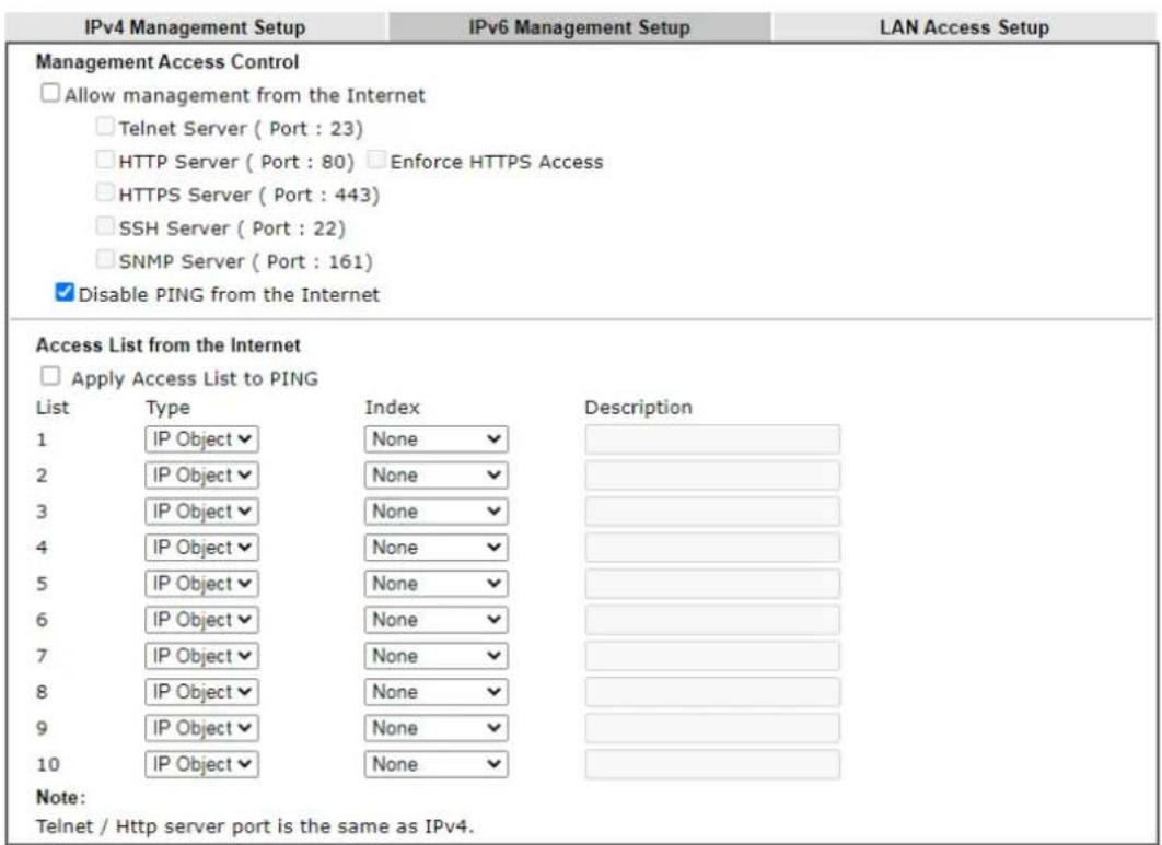
text_image
IPv4 Management Setup IPv6 Management Setup LAN Access Setup Management Access Control □ Allow management from the Internet □ Telnet Server ( Port : 23) □ HTTP Server ( Port : 80) □ Enforce HTTPS Access □ HTTPS Server ( Port : 443) □ SSH Server ( Port : 22) □ SNMP Server ( Port : 161) ✓ Disable PING from the Internet Access List from the Internet □ Apply Access List to PING List Type Index Description 1 IP Object None 2 IP Object None 3 IP Object None 4 IP Object None 5 IP Object None 6 IP Object None 7 IP Object None 8 IP Object None 9 IP Object None 10 IP Object None Note: Telnet / Http server port is the same as IPv4.OK
Available settings are explained as follows:
| Item | Description |
| Management Access Control | Allow management from the Internet - Enable the checkbox to allow system administrators to login from the Internet. There are several servers provided by the system to allow you managing the router from Internet. Check the box(es) to specify.Disable PING from the Internet - Check the checkbox to disable all PING packets from the Internet. For security issue, this function is enabled by default. |
| Access List from the Inernet | You could specify that the system administrator can only login from a specific host or network defined in the list. A maximum of three IPs/ subnet masks is allowed.Apply Access List to PING - When this option is checked and Disable PING from the Internet is unchecked, pings originating from the Internet will be accepted only if they are from one of the IP addresses and/or subnet masks specified below. This option has no effect if Disable PING from the Internet is checked, which blocks all pings from the Internet.Type - Select IP Object/Group or Hostname.Index - Select the index number of a configured IPv6 object. |
After finished the above settings, click OK to save the configuration.
LAN Access Setup
System Maintenance >> Management

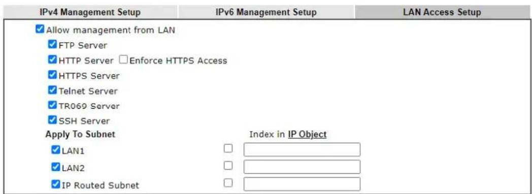
text_image
IPv4 Management Setup IPv6 Management Setup LAN Access Setup ✓ Allow management from LAN ✓ FTP Server ✓ HTTP Server □Enforce HTTPS Access ✓ HTTPS Server ✓ Telnet Server ✓ TR069 Server ✓ SSH Server Apply To Subnet Index in IP Object ✓ LAN1 □ ✓ LAN2 □ ✓ IP Routed Subnet □Note:
If an IP Object is specified in a LAN Subnet, the setting will be applied to the selected IP only.
OK
Available settings are explained as follows:
| Item | Description |
| Allow management from LAN | Enable the checkbox to allow system administrators to login from LAN interface. There are several servers provided by the system which allow you to manage the router from LAN interface. Check the box(es) to specify. |
| Apply To Subnet | Check the LAN interface for the administrator to use for accessing into web user interface of Vigor router. Index in IP Object- Enter the index number of the IP objectprofile. Related IP address will appear automatically. |
Select OK to save changes on the page.
VI-1-10 Panel Control
The behavior of the buttons on the front panel of the Vigor router can be customized as desired.
For Button
The Factory Reset and Wireless ON/OFF/WPS buttons on the front panel are enabled by default and can be enabled or disabled if required. Disabling the Factory Reset button will prevent tampering by unauthorized parties, or to avoid accidental triggering of a router reset when being used wake up LEDs. Disabling the wireless button will prevent changing the wireless setting when LED Sleep Mode is enabled, and the buttons are primarily used to turn the LEDs on and off.
Click the Button tab to get the following page.
System Maintenance >> Panel Control
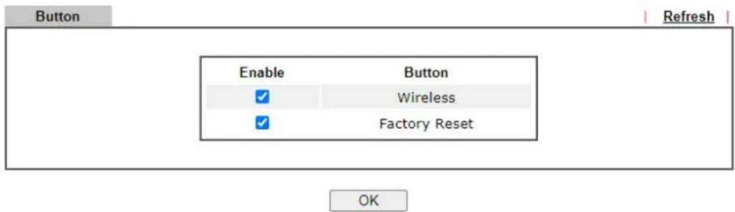
text_image
Button Enable Button ✓ Wireless ✓ Factory Reset OK RefreshAvailable settings are explained as follows:
| Item | Description |
| Refresh | Click to refresh the page to display the latest information. |
| Enable Wireless Button | The default value is Enabled.Deselect to disable the ability of the Wireless button to control WLAN and WPS functions.Disabling the wireless button only prevents it from being used to control WLAN functions. It can still be used to wake up the LEDs when LED sleep mode is enabled. |
| Enable Factory Reset Button | The default value is Enabled.Deselect to disable the reset function of the factory reset button.Disabling the Factory Reset button only prevents it from being used to reboot Vigor router with default settings. It can still be used to wake up the LEDs when LED sleep mode is enabled. |
After finished the above settings, click OK to save the configuration.
VI-1-11 Self-Signed Certificate
A self-signed certificate is a unique identification for the device (e.g., Vigor router) which generates the certificate by itself to ensure the router security. Such self-signed certificate is signed with its own private key.
The self-signed certificate will be applied in SSL VPN, HTTPS, and so on. In addition, it can be created for free by using a wide variety of tools.
System Maintenance >> Self-Signed Certificate
Self-Signed Certificate Information
| Certificate Name : | self-signed |
| Issuer : | C=TW, ST=HsinChu, L=HuKou, O=DrayTek Corp., OU=DrayTek Support, CN=Vigor Router |
| Subject : | C=TW, ST=HsinChu, L=HuKou, O=DrayTek Corp., OU=DrayTek Support, CN=Vigor Router |
| Subject Alternative Name : | |
| Valid From : | Feb 11 12:29:49 2019 GMT |
| Valid To : | Feb 10 12:29:49 2049 GMT |
| PEM Format Content : | ----BEGIN CERTIFICATE----MIIDijCCAnKgAwIBAgIJAJKZi/STtveRMA0GCSqGSIb3DQEBCwUAMHgxCzAJBgNV BAYTAIRXMRAwDgYDVQQIDAdIc2luQ2h1MQ4wDAYDVQQHDADIdUtvdTEWMBQGA1UE CgwNRHJheVRlayBDb3JwLjEYMBYGA1UECwwPRHJheVRlayBTdXBwb3JJOMRUwEwYD VQQDDAxWawdvcIBSb3V0ZXlWhhcmNfTkwMjExMTIyOTQ5WhcNNDkwMjEwMTIyOTQ5 Wjb4MQswCQYDVQQGEwJUVzEQMA4GA1UECAwHSHNpbkNodTEOMAwGA1UEBwwFSHV L b3UxFjAUBgNVBAoMDURyYXlUZWsgQ29ycC4xGDAWBgNVBAsMD0RyYXlUZWsgU3Vw cG9ydDEVMBMGA1UEAwwMVmlnb3IgUm91dGVyMIIBIjanBgkqhkiG9w0BAQEFAAO CAQ8AMIIBCgKCQEA0ytga60wzf3htgFPMDT2JIrRMsu02yviXPSkck/jj03phNf8 7EgIj3QutBhiD+DGXvBv3M+EbsbMZXPL0HVepF1sDZRZOZvedfE1kh4rRZ09boug 56QqLxUglzGR+jWzoEn8SCcpvJ8r5LWq78JQwn+XXFe9kth3W8MVP0Z7Tip1uaN VX7lIAcZqjwNQwyEw+7NHcrcLH/xGj0nZ3rdbJyDHHiu62wgxnA203Zq2A2fzwI rBB8NlweISDDZyk/wOMln6JuWz0Tz3Wj5kzpynUIkHo0Qoas2Ybxolm3DRNiT0b4 AMxthJ2PakRAq648d4KAmwbZxgChw3DyGXaFUQIDAQBoxcwFTATBGnvHSUEDDAK Bggr8gEFBQcDATANBgkqhkiG9w0BAQsFAAOCAQEAnA+05/kppOxKpv8K766tKwXd s25b1ypQGFfqxHXbX0dhkAsBceHp4TeCnfuuuc88UCxsrs6vw6kQfio+08rLVTzp1 PqKr8tOpcbADn9LLwzLk5UKI7eoLnfZvTiktSKpz68SYZYDxTDIZjGAJny21t6 l8z14/sioMDCZZIU2nmmRdkRVG9Q6xe5gY/TfJw5+vI8LfcNU52PJNeH4XM0AnmG kaDQzdpm2rsep9t57shl53xRXPuYrJZkL6Z/zMZA6FQJpE1kraVTlOCYNiYQRzB MHo7pC0gJdw4hB6gEWku3J/RnnFNpvudRRhHJBK9i6kMEFbjGyHdT31BdvsDEw== ----END CERTIFICATE---- |
Note:
- Please setup the System Maintenance >> Time and Date correctly before you try to regenerate a self-signed certificate!!
- The Time Zone MUST be setup correctly!!
Regenerate
Click Regeneration to open Regenerate Self-Signed Certificate window. Enter all the information that the window request such as certificate name (used for identifying different certificate), subject alternative name type and relational settings for subject name. Then click GENERATE.
System Maintenance >> Regenerate Self-Signed Certificate
Regenerate Self-Signed Certificate
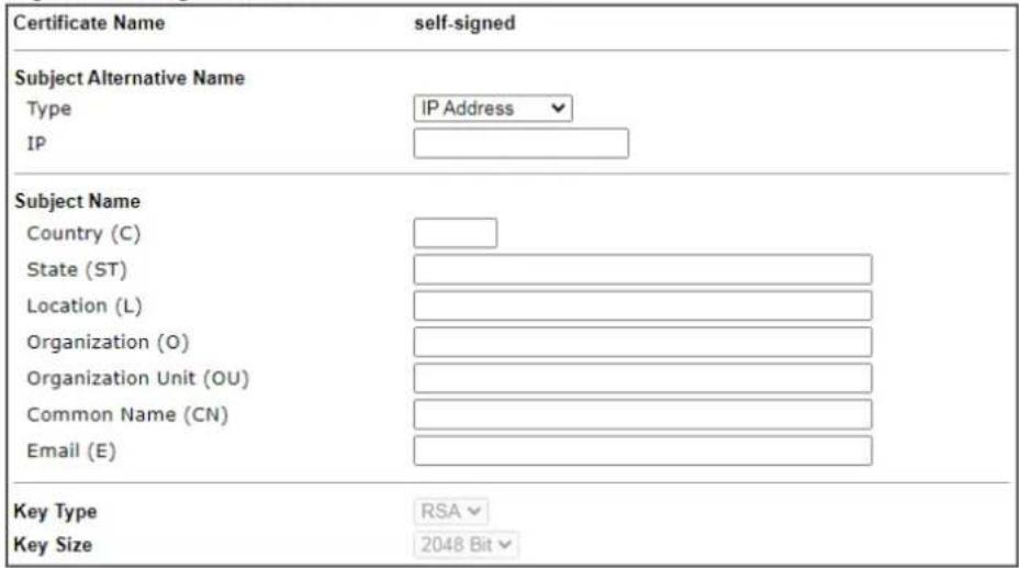
text_image
Certificate Name self-signed Subject Alternative Name Type IP Address IP Subject Name Country (C) State (ST) Location (L) Organization (O) Organization Unit (OU) Common Name (CN) Email (E) Key Type RSA Key Size 2048 BitGenerate
VI-1-12 Reboot System
The Web user interface may be used to restart your router. Click Reboot System from System Maintenance to open the following page.
System Maintenance >> Reboot System
Reboot System
Do you want to reboot your router?
Using current configuration
○ Using factory default configuration
Reboot Now
Auto Reboot Time Schedule
Schedule Profile : None ▼, None ▼, None ▼, None ▼
Note: Action and Duration Time settings will be ignored.
OK Cancel
Schedule Profile - You can Enter four sets of time schedule for performing system reboot. All the schedules can be set previously in Applications >> Schedule web page and you can use the number that you have set in that web page.
If you want to reboot the router using the current configuration, check Using current configuration and click Reboot Now. To reset the router settings to default values, check Using factory default configuration and click Reboot Now. The router will take 5 seconds to reboot the system.

Info
When the system pops up Reboot System web page after you configure web settings, please click Reboot Now to reboot your router for ensuring normal operation and preventing unexpected errors of the router in the future.
VI-1-13 Firmware Upgrade
Click System Maintenance>> Firmware Upgrade to proceed to firmware upgrade.
System Maintenance >> Firmware Upgrade

Download Link: https://www.draytek.com/support/latest-firmwares/
Web Firmware Upgrade
Select a firmware file.
選擇檔案 未選擇任何檔案
Click Upgrade to upload the file.
Upgrade
Preview
Note:
Upgrade using the ALL file will retain existing router configuration, whereas using the RST file will reset the configuration to factory defaults.
Click Select to specify the one you just download. After choosing the file you want, click Upgrade. The system will upgrade the firmware of the router automatically.
VI-1-14 Activation
There are three ways to activate WCF on vigor router, using Service Activation Wizard, by means of CSM>>Web Content Filter Profile or via System Maintenance>>Activation.
After you have finished the setting profiles for WCF (refer to Web Content Filter Profile), it is the time to activate the mechanism for your computer.
Click System Maintenance>>Activation to open the following page for accessing http://myvigor.draytek.com.
System Maintenance >> Activation Activate via interface : auto-selected
Web-Filter License
[Status: Not Activated]
Activate
Authentication Message
Note:
- If you want to use email alert or syslog, please configure the SysLog/Mail Alert Setup page.
- If you change the service provider, the configuration of the function will be reset.
OK
Cancel
Available settings are explained as follows:
| Item | Description |
| Activate via Interface Choose WAN interface used by such device for activating Web Content Filter. | |
| Activate | The Activate link brings you accessing into www.vigorpro.com to finish the activation of the account and the router. |
| Authentication Message | As for authentication information of web filter, the process of authenticating will be displayed on this field for your reference. |
Below shows the successful activation of Web Content Filter:
System Maintenance >> Activation
Activate via interface : auto-selected
Web-Filter License
Activate
[Status: [Start Date:2021-03-28 Expire Date:2021-04-27]
Authentication Message
OK
Cancel
VI-2 Bandwidth Management
Sessions Limit
A PC with private IP address can access to the Internet via NAT router. The router will generate the records of NAT sessions for such connection. The P2P (Peer to Peer) applications (e.g., BitTorrent) always need many sessions for procession and also they will occupy over resources which might result in important accesses impacted. To solve the problem, you can use limit session to limit the session procession for specified Hosts.
Bandwidth Limit
The downstream or upstream from FTP, HTTP or some P2P applications will occupy large of bandwidth and affect the applications for other programs. Please use Limit Bandwidth to make the bandwidth usage more efficient.
Quality of Service (QoS)
Deploying QoS (Quality of Service) management to guarantee that all applications receive the service levels required and sufficient bandwidth to meet performance expectations is indeed one important aspect of modern enterprise network.
One reason for QoS is that numerous TCP-based applications tend to continually increase their transmission rate and consume all available bandwidth, which is called TCP slow start. If other applications are not protected by QoS, it will detract much from their performance in the overcrowded network. This is especially essential to those are low tolerant of loss, delay or jitter (delay variation).
Another reason is due to congestions at network intersections where speeds of interconnected circuits mismatch or traffic aggregates, packets will queue up and traffic can be throttled back to a lower speed. If there's no defined priority to specify which packets should be discarded (or in another term "dropped") from an overflowing queue, packets of sensitive applications mentioned above might be the ones to drop off. How this will affect application performance?
There are two components within Primary configuration of QoS deployment:
- Classification: Identifying low-latency or crucial applications and marking them for high-priority service level enforcement throughout the network.
- Scheduling: Based on classification of service level to assign packets to queues and associated service types
The basic QoS implementation in Vigor routers is to classify and schedule packets based on the service Enterformation in the IP header. For instance, to ensure the connection with the headquarter, a teleworker may enforce an index of QoS Control to reserve bandwidth for HTTPS connection while using lots of application at the same time.
One more larger-scale implementation of QoS network is to apply DSCP (Differentiated Service Code Point) and IP Precedence disciplines at Layer 3. Compared with legacy IP Precedence that uses Type of Service (ToS) field in the IP header to define 8 service classes, DSCP is a successor creating 64 classes possible with backward IP Precedence compatibility. In a QoS-enabled network, or Differentiated Service (DiffServ or DS) framework, a DS domain owner should sign a Service License Agreement (SLA) with other DS domain owners to define the service level provided toward traffic from different domains. Then each DS node in these domains will perform the priority treatment. This is called per-hop-behavior (PHB). The definition of PHB includes Expedited Forwarding (EF), Assured Forwarding (AF), and Best Effort (BE). AF defines the four classes of delivery (or forwarding) classes and three levels of drop precedence in each class.
Vigor routers as edge routers of DS domain shall check the marked DSCP value in the IP header of bypassing traffic, to allocate certain amount of resource execute appropriate policing, classification or scheduling. The core routers in the backbone will do the same checking before executing treatments in order to ensure service-level consistency throughout the whole QoS-enabled network.
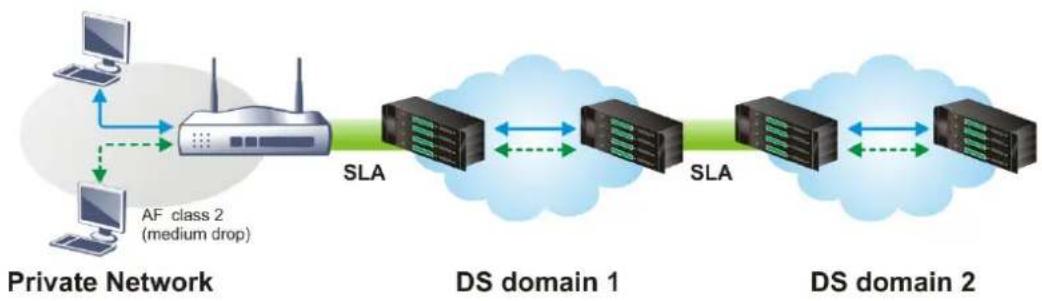
flowchart
graph LR
    A["Private Network"] -->|AF class 2 (medium drop)| B["SLA"]
    B --> C["DS domain 1"]
    C <--> D["SLA"]
    D <--> E["DS domain 2"]
    E --> F["SLA"]
    F <--> G["DS domain 1"]
    G <--> H["SLA"]
However, each node may take different attitude toward packets with high priority marking since it may bind with the business deal of SLA among different DS domain owners. It's not easy to achieve deterministic and consistent high-priority QoS traffic throughout the whole network with merely Vigor router's effort.
Web User Interface
Below shows the menu items for Bandwidth Management.
Bandwidth Management
Sessions Limit
Bandwidth Limit
Quality of Service
Applications
VI-2-1 Sessions Limit
In the Bandwidth Management menu, click Sessions Limit to open the web page.
Bandwidth Management >> Sessions Limit
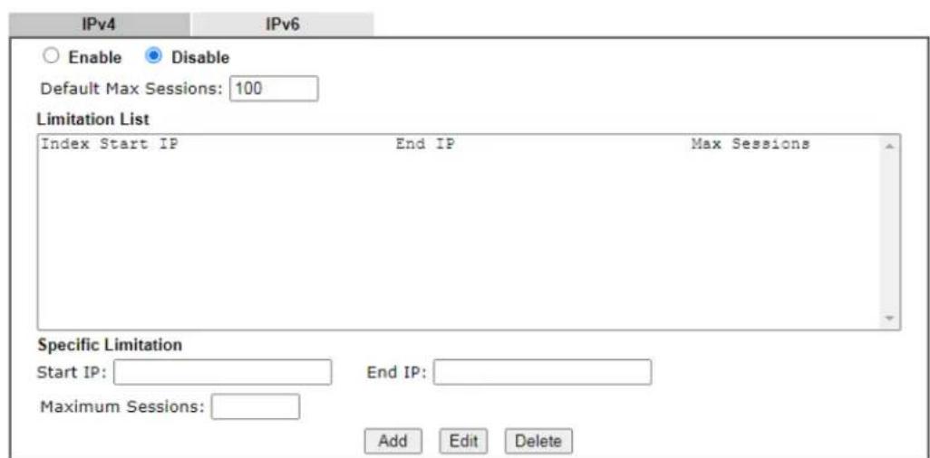
text_image
IPv4 IPv6 Enable Disable Default Max Sessions: 100 Limitation List Index Start IP End IP Max Sessions Specific Limitation Start IP: End IP: Maximum Sessions: Add Edit Delete
text_image
Administration Message (Max 255 characters) Default Message You have reached the maximum number of permitted Internet sessions.Please close one or more applications to allow further Internet access.
Contact your system administrator for further information.

text_image
Time Schedule Schedule Profile : None ▼, None ▼, None ▼, None ▼ Note: Action and Idle Timeout settings will be ignored.OK
To activate the function of limit session for IPv4 and/or IPv6, simply click Enable and set the default session limit.
Available settings are explained as follows:
| Item | Description |
| Session Limit Enable - Click | this button to activate the function of limit session. |
| Disable - Click this button to close the function of limit session. | |
| Default Max Sessions - Defines the default session number | |
| used for each computer in LAN. | |
| Limitation List Displays a list of specific limitations that you set on this web page. | |
| Specific Limitation Start IP- | Defines the start IP address for limit session.End IP - Defines the end IP address for limit session.Maximum Sessions - Defines the available session number for each host in the specific range of IP addresses. If you do not set the session number in this field, the system will use the default session limit for the specific limitation you set for each index.Add - Adds the specific session limitation onto the list above.Edit - Allows you to edit the settings for the selected limitation.Delete - Remove the selected settings existing on the limitation list. |
| Administration Message Enter the words which will be displayed when reaches the maximum number of Internet sessions permitted.Default Message - Click this button to apply the default message offered by the router. | |
| Time Schedule Schedule Profile - You can Enter four sets of time schedule for your request. All the schedules can be set previously in Application >> Schedule web page and you can use the number that you have set in that web page. | |
After finishing all the settings, please click OK to save the configuration.
VI-2-2 Bandwidth Limit
In the Bandwidth Management menu, click Bandwidth Limit to open the web page.
Bandwidth Management >> Bandwidth Limit
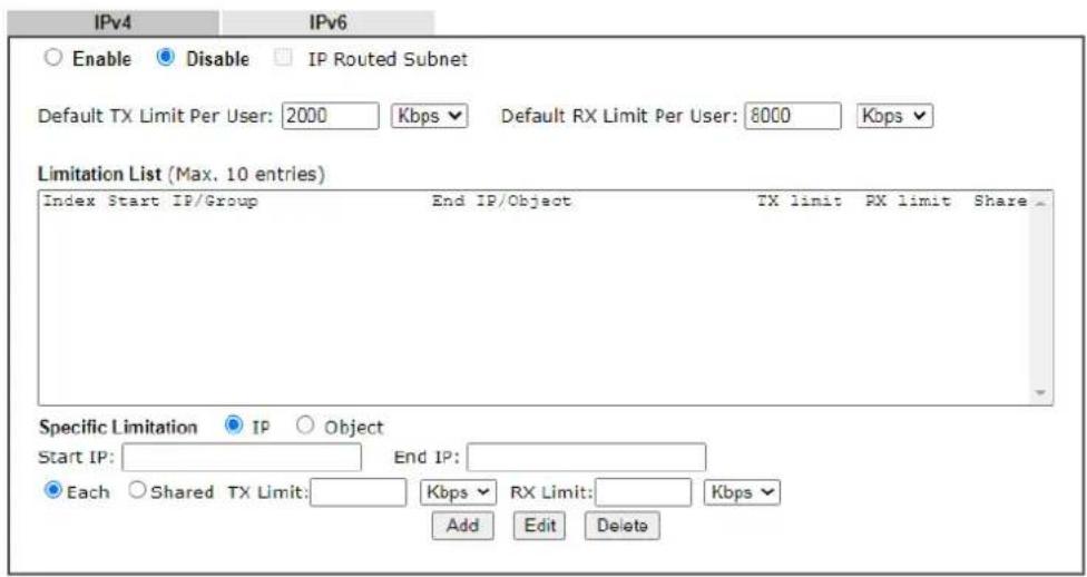
text_image
IPv4 IPv6 Enable Disable IP Routed Subnet Default TX Limit Per User: 2000 Kbps Default RX Limit Per User: 8000 Kbps Limitation List (Max. 10 entries) Index Start IP/Group End IP/Object TX limit PX limit Share Specific Limitation IP Object Start IP: End IP: Each Shared TX Limit: Kbps RX Limit: Kbps Add Edit Delete
text_image
Auto-Adjustment Allow auto adjustment to assign available bandwidth equally to active user. Smart Bandwidth Limit For any LAN IP Not in Limitation List, whose session number exceeds 1000 TX Limit : 200 Kbps RX Limit : 800 KbpsNote:
For TX/RX, a setting of "0" means unlimited bandwidth.

text_image
Time Schedule Index(1-15) in Schedule Setup: Note: Action and Idle Timeout settings will be ignored.
To activate the function of limit bandwidth for IPv4 and / or IPv6, simply click Enable and set the default upstream and downstream limit.
Available settings are explained as follows:
| Item | Description |
| Bandwidth Limit Enable - Click this button to activate the function of limit bandwidth.IP Routed Subnet - Check this box to apply the bandwidth limit to the second subnet specified in LAN>>General Setup. It is available for IPv4 settings only.Disable - Click this button to close the function of limit bandwidth.Default TX limit Per User- Define the default speed of the upstream for each computer in LAN.Default RX limit Per User- Define the default speed of the downstream for each computer in LAN. | |
| Limitation List Display a list of specific limitations that you set on this web page. | |
| Specific Limitation Start IP - Define the start IP address for limit bandwidth. | |
| End IP - Define the end IP address for limit bandwidth.Each /Shared - Select Each to make each IP within the range of Start IP and End IP having the same speed defined in TX limit and RX limit fields; select Shared to make all the IPs within the range of Start IP and End IP share the speed defined in TX limit and RX limit fields.TX limit - Define the limitation for the speed of the upstream. If you do not set the limit in this field, the system will use the default speed for the specific limitation you set for each index.RX limit - Define the limitation for the speed of the downstream. If you do not set the limit in this field, the system will use the default speed for the specific limitation you set for each index.Add - Add the specific speed limitation onto the list above.Edit - Allow you to edit the settings for the selected limitation.Delete - Remove the selected settings existing on the limitation list. | |
| Allow auto adjustment... | Check this box to make the best utilization of available bandwidth. |
| Smart Bandwidth Limit Check this box to have the bandwidth limit determined by the system automatically.TX limit - Define the limitation for the speed of the upstream. If you do not set the limit in this field, the system will use the default speed for the specific limitation you set for each index.RX limit - Define the limitation for the speed of the downstream. If you do not set the limit in this field, the system will use the default speed for the specific limitation you set for each index. | |
| Time Schedule Schedule Profile - You can Enter four sets of time schedule for your request. All the schedules can be set previously in Applications >> Schedule web page and you can use the number that you have set in that web page. | |
VI-2-3 Quality of Service
In the Bandwidth Management menu, click Quality of Service to open the web page.
Bandwidth Management >> Quality of Service
| General Setup | Set to Factory Default | ||||||||||||
| Index | Enable | Direction | Inbound/ Outbound Bandwidth | Class 1 | Class 2 | Class 3 | Others | Status | |||||
| WAN2 | BOTH | 100 | Mbps / | 100 | Mbps | 25 | % | 25 | % | 25 | % | Status | |
| LTE | BOTH | 100 | Mbps / | 100 | Mbps | 25 | % | 25 | % | 25 | % | Status | |
Note:
QoS may not work properly if the bandwidth entered is not correct. Before enable QoS, you may run speed test (from e.g., http://speedtest.net) or contact your ISP for the accurate bandwidth.
Class Rule
| Index | Enable | QoS Class | Local Address | Remote Address | DSCP | Service Type |
| Add |
Note:
- The packets that don't match any class rules above will be classified into 'Others'
- Go to User Defined Service Type to edit/delete user-defined service type profiles.
VoIP Prioritization
| Enable the First Priority for VoIP SIP/RTP: | |
| SIP UDP Port: 5060 (Default: 5060) |
Tag Outbound Traffic
| Class 1 | Add DSCP or Precedence Value | Default |
| Class 2 | Add DSCP or Precedence Value | Default |
| Class 3 | Add DSCP or Precedence Value | Default |

Available settings are explained as follows:
| Item | Description |
| General Setup | Index - Display the WAN interface number link that you can edit.Enable - Check the box to enable the QoS function for WAN interface. If it is enabled, you can configure general QoS setting for each WAN interface.Direction - Define which traffic the QoS Control settings will apply to.IN- apply to incoming traffic only.OUT-apply to outgoing traffic only.BOTH- apply to both incoming and outgoing traffic.Inbound/Outbound Bandwidth - Set the connecting rate of data input/output for other WAN. For example, if your ADSL supports 1M of downstream and 256K upstream, please set 1000kbps for this box. The default value is 10000kbps.Class 1 ~ 3 / Others - Define the ratio of bandwidth to upstream speed and bandwidth to downstream speed. There are four queues allowed for QoS control. The first three (Class 1 to Class 3) class rules can be adjusted for your necessity. In which, the “Others” field is used for the packets which are not suitable for the three class rules.Status - Display the online statistics of WAN interface. |
| Class Rule Define and list | the Class rules.Index - Displays the class number that you can edit.Enable - Displays the status of this class rule.QoS Class - Displays the QoS class level.Local Address - Displays the local IP address for the rule.Remote Address - Displays the remote IP address for the rule.DSCP - Displays the levels of the data for processing with QoS control.Service Type - Displays detailed settings for the service type.Add - Click it to create a class rule for QoS. |
| VoIP Prioritization | Enable the First Priority for VoIP SIP/RTP - Select to allow VoIP traffic to receive the highest priority.SIP UDP Port - Port number to be monitored for SIP traffic. - Click this icon to display the VoIP QoS Status. - Click this icon to display the VoIP QoS Status. |
| Tag Outbound Traffic | Tag the outgoing traffic with the DSCP or Precedence value.Add DSCP or Precedence Value for Class 1 to Class 3 - Check to apply the DSCP or precedence value for each class. |
To save changes, click OK; to discard changes, click Cancel.
Click the WAN2/LTE link to access into next page for the general setup of WAN interface. As to class rule, simply click the Edit link to access into next for configuration.
You can configure general setup for the WAN interface, edit the Class Rule, and edit the Service Type for the Class Rule for your request.
Online Statistics
Click the WAN2/LTE link to access into next page for the general setup of WAN interface. As to class rule, simply click the Edit link to access into next for configuration.
Bandwidth Management >> Quality of Service
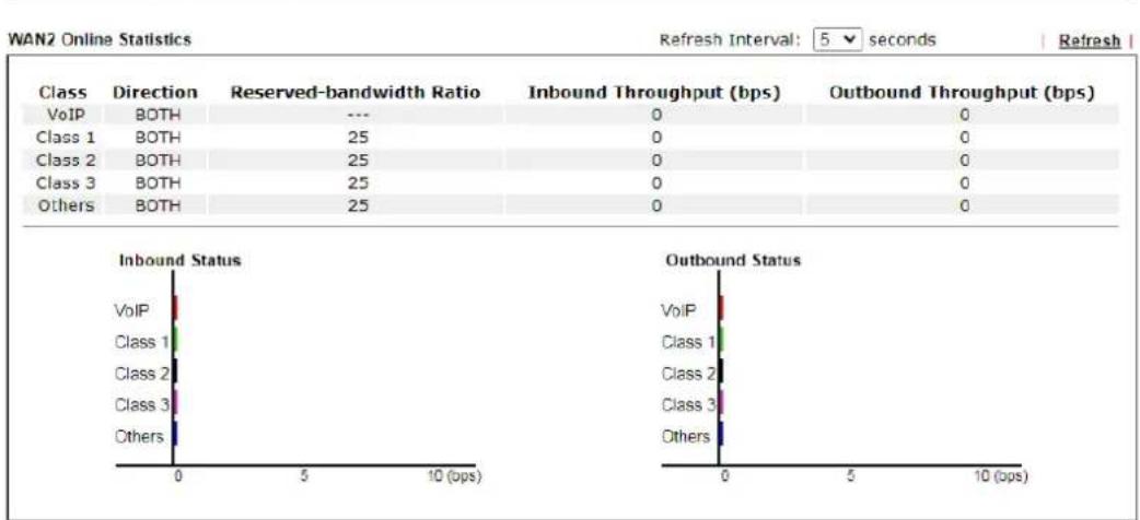
Cancel
General Setup for WAN Interface
Click WAN interface number link to configure the limited bandwidth ratio for QoS of the WAN interface.
Bandwidth Management >> Quality of Service >> WAN2
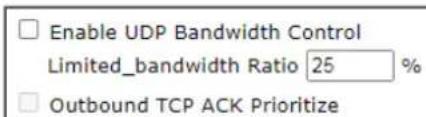
text_image
Enable UDP Bandwidth Control Limited_bandwidth Ratio 25 % Outbound TCP ACK Prioritize
Available settings are explained as follows:
| Item | Description |
| Enable UDP Bandwidth Control | Set the limited bandwidth ratio. This is a protection of TCP application traffic since UDP application traffic such as streaming video will exhaust lots of bandwidth.Limited_bandwidth Ratio - The ratio typed here is reserved for limited bandwidth of UDP application. |
| Outbound TCP ACK Prioritize | The difference in bandwidth between download and upload are great in ADSL2+ environment. For the download speed might be impacted by the uploading TCP ACK, you can check this box to push ACK of upload faster to speed the network traffic. |

Info
The rate of outbound/inbound must be smaller than the real bandwidth to ensure correct calculation of QoS. It is suggested to set the bandwidth value for inbound/outbound as 80% - 85% of physical network speed provided by ISP to maximize the QoS performance.
Edit the Class Rule for QoS
- To add a rule, click Add to bring up the configuration page. To edit an existing rule, select the rule by clicking the radio button in front of the rule, and then click Edit to bring up the configuration page.
Class Rule
| Index | Enable | Qos Class | Local Address | Remote Address | DSCP | Service Type |
| Add | ||||||
| Note:1. The packets that don't match any class rules above will be classified into 'Others'2. Go toUser Defined Service Typeto edit/delete user-defined service type profiles3. Hardware Acceleration will not work on wired WAN interfaces with QoS enabled. | ||||||
VoIP PrioritizationEnable the First Priority for VoIP SIP/RTP:SIP UDP Port:5060(Default 5060)  | ||||||
| Tag Outbound TrafficClass 1Add DSCP or Precedence ValueDefaultClass 2Add DSCP or Precedence ValueDefaultClass 3Add DSCP or Precedence ValueDefaultOK Cancel | ||||||
- For adding a new rule, click Add to open the following page.
Bandwidth Management >> Quality of Service
Rule 1
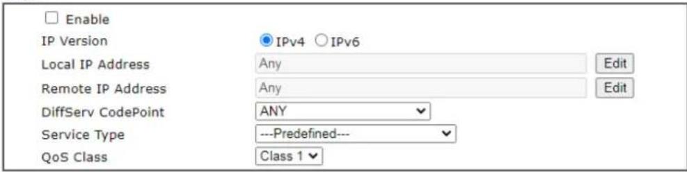
text_image
Enable IP Version Local IP Address Remote IP Address DiffServ CodePoint Service Type QoS Class IPv4 IPv6 Any Any ANY ---Predefined--- Class 1 Edit Edit
Available settings are explained as follows:
| Item | Description |
| Enable Check this box to invoke these settings. | |
| Ethernet Type Please specify which protocol (IPv4 or IPv6) will be used for this rule. | |
| Local Address | Click the Edit button to set the local IP address (on LAN) for the rule. |
| Remote Address | Click the Edit button to set the remote IP address (on LAN/WAN) for the rule.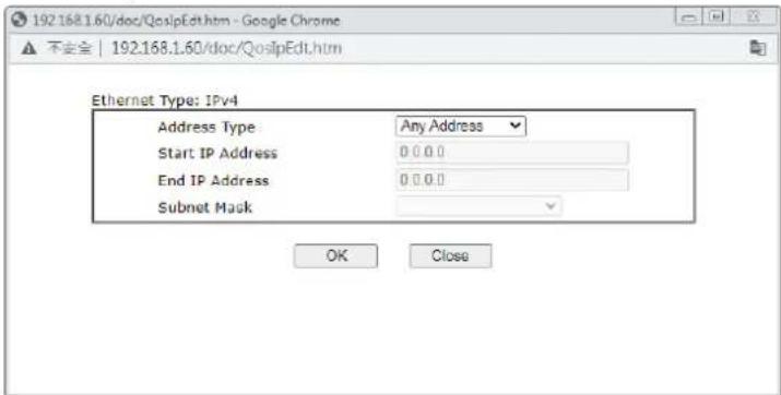 Address Type - Determine the address type for the source address.For Single Address, you have to fill in Start IP address.For Range Address, you have to fill in Start IP address and End IP address.For Subnet Address, you have to fill in Start IP address and Subnet Mask. Address Type - Determine the address type for the source address.For Single Address, you have to fill in Start IP address.For Range Address, you have to fill in Start IP address and End IP address.For Subnet Address, you have to fill in Start IP address and Subnet Mask. |
| DiffServ CodePoint All | the packets of data will be divided with different levels and will be processed according to the level type by the system. Please assign one of the levels of the data for processing with QoS control. |
| Service Type It determines the service type of the data for processing with QoS control. It can also be edited. You can choose the predefined service type from the Service Type drop down list. Those types are predefined in factory. Simply choose the one that you want for using by current QoS. | |
- After finishing all the settings here, please click OK to save the configuration.
By the way, you can set up to 20 rules for one Class. If you want to edit an existed rule, please select the radio button of that one and click Edit to open the rule edit page for modification.
Class Rule
| Index | Enable | QoS Class | Local Address | Remote Address | DSCP | Service Type |
| 1 | Class1 | Any | Any | ANY | ANY | |
| Add |
Note:
-
The packets that don't match any class rules above will be classified into 'Others'
-
Go to User Defined Service Type to edit/delete user-defined service type profiles.
VoIP Prioritization
| Enable the First Priority for VoIP SIP/RTP:SIP UDP Port:5060 (Default:5060) |  |
VI-3 Central Management (AP)
VigorLTE 200 can manage the access points supporting AP management via Central AP Management.
AP Map
AP Map is helpful to determine the best location for VigorAP in a room. A floor plan of a room is required to be uploaded first. By dragging and dropping available VigorAP icon from the list to the floor plan, the placement with the best wireless coverage will be clearly indicated through simulated signal strength
AP Maintenance
Vigor router can execute configuration backup, configuration restoration, firmware upgrade and remote reboot for the APs managed by the router. It is very convenient for the administrator to process maintenance without accessing into the web user interface of the access point.
Load Balance for AP
The parameters configured for Load Balance can help to distribute the traffic for all of the access points registered to Vigor router. Thus, the bandwidth will not be occupied by certain access points.
AP Load Balance (Traffic overload)
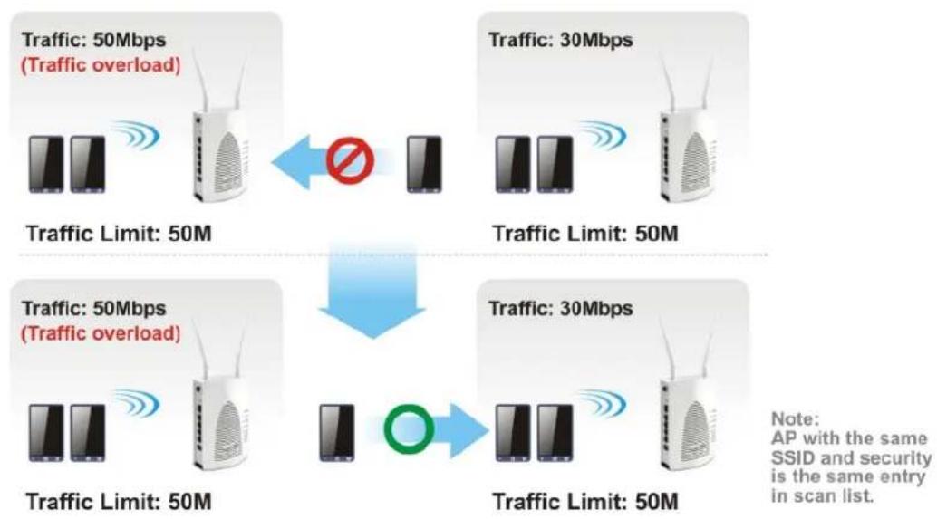
flowchart
graph TD
    A["Wireless Device 1"] -->|Traffic: 50Mbps (Traffic overload)| B["Stop/Stop icon"]
    C["Wireless Device 2"] -->|Traffic: 30Mbps| D["Stop/Stop icon"]
    E["Wireless Device 3"] -->|Traffic: 50Mbps| F["Stop/Stop icon"]
    G["Wireless Device 4"] -->|Traffic: 50Mbps| H["Stop/Stop icon"]
    I["Wireless Device 5"] -->|Traffic: 50Mbps| J["Stop/Stop icon"]
    K["Wireless Device 6"] -->|Traffic: 30Mbps| L["Stop/Stop icon"]
    M["Wireless Device 7"] -->|Traffic: 50Mbps| N["Stop/Stop icon"]
    O["Wireless Device 8"] -->|Traffic: 50Mbps| P["Stop/Stop icon"]
    Q["Wireless Device 9"] -->|Traffic: 50Mbps| R["Stop/Stop icon"]
    S["Wireless Device 10"] -->|Traffic: 50Mbps| T["Stop/Stop icon"]
    U["Wireless Device 11"] -->|Traffic: 50Mbps| V["Stop/Stop icon"]
    W["Wireless Device 12"] -->|Traffic: 50Mbps| X["Stop/Stop icon"]
    Y["Wireless Device 13"] -->|Traffic: 50Mbps| Z["Stop/Stop icon"]
    AA["Wireless Device 14"] -->|Traffic: 50Mbps| AB["Stop/Stop icon"]
    AC["Wireless Device 15"] -->|Traffic: 50Mbps| AD["Stop/Stop icon"]
    AE["Wireless Device 16"] -->|Traffic: 50Mbps| AF["Stop/Stop icon"]
    AG["Wireless Device 17"] -->|Traffic: 50Mbps| AH["Stop/Stop icon"]
    AI["Wireless Device 18"] -->|Traffic: 50Mbps| AJ["Stop/Stop icon"]
    AK["Wireless Device 19"] -->|Traffic: 50Mbps| AL["Stop/Stop icon"]
    AM["Wireless Device 20"] -->|Traffic: 50Mbps| AN["Stop/Stop icon"]
    AO["Wireless Device 21"] -->|Traffic: 50Mbps| AP["Stop/Stop icon"]
    AQ["Wireless Device 22"] -->|Traffic: 50Mbps| AR["Stop/Stop icon"]
    AS["Wireless Device 23"] -->|Traffic: 50Mbps| AT["Stop/Stop icon"]
    AU["Wireless Device 24"] -->|Traffic: 50Mbps| AV["Stop/Stop icon"]
    AW["Wireless Device 25"] -->|Traffic: 50Mbps| AX["Stop/Stop icon"]
    AY["Wireless Device 26"] -->|Traffic: 50Mbps| AZ["Stop/Stop icon"]
    BA["Wireless Device 27"] -->|Traffic: 50Mbps| BB["Stop/Stop icon"]
    BC["Wireless Device 28"] -->|Traffic: 50Mbps| BD["Stop/Stop icon"]
    BE["Wireless Device 29"] -->|Traffic: 50Mbps| BF["Stop/Stop icon"]
    BG["Wireless Device 30"] -->|Traffic: 50Mbps| BH["Stop/Stop icon"]
    BI["Wireless Device 31"] -->|Traffic: 50Mbps| BJ["Stop/Stop icon"]
    BK["Wireless Device 32"] -->|Traffic: 50Mbps| BKB["Open circle"]
    BL["Wireless Device 33"] -->|Traffic: 50Mbps| BLB["Open circle"]
    BM["Wireless Device 34"] -->|Traffic: 50Mbps| BN["Open circle"]
    BO["Wireless Device 35"] -->|Traffic: 50Mbps| BNB["Open circle"]
    BP["Wireless Device 36"] -->|Traffic: 50Mbps| BPB["Open circle"]
    BPB --> BA["Note: AP with the same SSID and security is the same entry in scan list."]
Web User Interface
Central Management AP
Dashboard
Status
WLAN Profile
AP Maintenance
Traffic Graph
Temperature Sensor
Event Log
Total Traffic
Station Number
Load Balance
Function Support List
VI-3-1 Dashboard
This page shows VigorAP's information about Status, Event Log, Total Traffic or Station Number by displaying VigorAP icon, text and histogram. Just move and click your mouse cursor on Status, Event Log, Total Traffic or Station Number. Corresponding web pages will be open immediately.
Central AP Management >> Dashboard
Status
Event Log
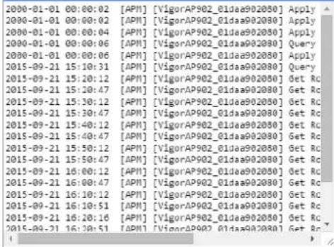
text_image
2000-01-01 00:00:02 [API] [VigorAP902_01dae902050] Apply 2000-01-01 00:00:02 [API] [VigorAP902_01dae902050] Apply 2000-01-01 00:00:04 [API] [VigorAP902_01dae902050] Apply 2000-01-01 00:00:06 [API] [VigorAP902_01dae902050] Query 2000-01-01 00:00:06 [API] [VigorAP902_01dae902050] Apply 2015-09-21 15:10:31 [API] [VigorAP902_01dae902050] Query 2015-09-21 15:20:12 [API] [VigorAP902_01dae902050] Get Rc 2015-09-21 15:20:47 [API] [VigorAP902_01dae902050] Get Rc 2015-09-21 15:30:12 [API] [VigorAP902_01dae902050] Get Rc 2015-09-21 15:30:47 [API] [VigorAP902_01dae902050] Get Rc 2015-09-21 15:40:12 [API] [VigorAP902_01dae902050] Get Rc 2015-09-21 15:40:47 [API] [VigorAP902_01dae902050] Get Rc 2015-09-21 15:50:12 [API] [VigorAP902_01dae902050] Get Rc 2015-09-21 15:50:47 [API] [VigorAP902_01dae902050] Get Rc 2015-09-21 16:00:12 [API] [VigorAP902_01dae902050] Get Rc 2015-09-21 16:00:47 [API] [VigorAP902_01dae902050] Get Rc 2015-09-21 16:10:12 [API] [VigorAP902_01dae902050] Get Rc 2015-09-21 16:10:51 [API] [VigorAP902_01dae902050] Get Rc 2015-09-21 16:20:16 [API] [VigorAP902_01dae902050] Get Rc 2015-09-21 16:30:51 [API] [VigorAP902_01dae902050] Get RcTotal Traffic
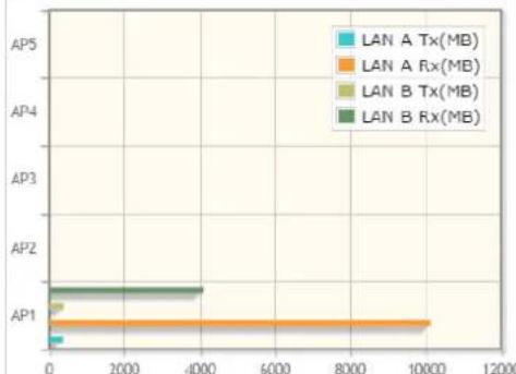
bar
| Category | LAN A Tx(MB) | LAN A Rx(MB) | LAN B Tx(MB) | LAN B Rx(MB) | |---|---|---|---|---| | AP1 | 200 | 10000 | 300 | 4000 | | AP2 | 0 | 0 | 0 | 0 | | AP3 | 0 | 0 | 0 | 0 | | AP4 | 0 | 0 | 0 | 0 | | AP5 | 0 | 0 | 0 | 0 |Station Number
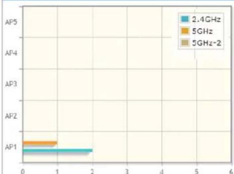
bar
| Category | 2.4GHz | 5GHz | 5GHz-2 | |---|---|---|---| | AP1 | 0.8 | 0.9 | 0.9 | | AP2 | 0.0 | 0.0 | 0.0 | | AP3 | 0.0 | 0.0 | 0.0 | | AP4 | 0.0 | 0.0 | 0.0 | | AP5 | 0.0 | 0.0 | 0.0 |AP1-- IP:172.17.3.114 Device Name:VigorAP902
Note: Only browser supporting HTML5 can display dashboard correctly.
AP1-- IP:172.17.3.114 Device Name:VigorAP902
To access into the web user interface of VigorAP, simply move your mouse cursor on the VigorAP icon and click it. The system will guide you to access into the web user interface of VigorAP.
VI-3-2 Status
This page displays current status (online, offline or SSID hidden, IP address, encryption, channel, version, password and etc.) of the access points managed by Vigor router. Please open Central AP Management>>Function Support List to check what AP Models are supported.
Central Management >> AP >> Status

text_image
Index Device Name IP Address SSID Ch. STA List AP List Uptime Ver. Password Information Clear RefreshNote:

: Online

Offline

: Hidden SSID
Maximum support 2 APs.
When AP Devices connect via an intermediary switch, please ensure that UDP:4944 port and the HTTP port of AP Devices are not blocked so that the AP status can be retrieved.
Available settings are explained as follows:
| Item | Description |
| Index Click the index number | per link for viewing the settings summary of the access point. |
| Device Name The name of | the AP managed by Vigor router will be displayed here. |
| IP Address Display the true | IP address of the access point. |
| SSID | Display the SSID configured for the access point(s) connected to VigorLTE 200. |
| Ch. Display the channel used by the access point. | |
| STA List Display the number of wireless clients (stations) connecting to the access point.In which, 0/64 means that up to 64 clients are allowed to connect to the access point. But, now no one connects to the access point.The number displayed on the left side means 2.4GHz; and the number displayed on the right side means 5GHz. | |
| AP List Display the number of the AP around the device. | |
| Uptime Display the duration of the AP powered up. | |
| Version | Display the firmware version used by the access point. |
| Password VigorLTE 200 can get related information of the access point by accessing into the web user interface of the access point.This button is used to modify the logging password of the connected access point. | |
| Information | Click Details to open a window of detailed information related to the selected VigorAP. |
VI-3-3 WLAN Profile
WLAN profile is used to apply to a selected access point. It is very convenient for the administrator to configure the setting for access point without opening the web user interface of the access point.
Central Management >> AP >> WLAN Profile
Set to Factory Default
| Profile | Name | Main SSID | Security | Multi-SSID | WLAN ACL | Rate Ctrl | Clone | To AP | To Local |
| 1 | Default | DrayTek-LAN-A | WPA+WPA2/PSK | Enable | None | None | |||
| 2 | --- | --- | --- | --- | --- | --- | --- | --- | --- |
| 3 | --- | --- | --- | --- | --- | --- | --- | --- | --- |
| 4 | --- | --- | --- | --- | --- | --- | --- | --- | --- |
| 5 | --- | --- | --- | --- | --- | --- | --- | --- | --- |
Click the number link of the selected profile to modify the content of the profile. Available settings are explained as follows:
| Item | Description |
| Profile There are five WLAN | N profiles offered to be configured. Simply click the index number link to open the modification page. |
| Name Display the name of | the profile.The default profile cannot be renamed. |
| Main SSID | Display the SSID configured by such wireless profile. |
| Security | Display the security mode selected by such wireless profile. |
| Multi-SSID Enable means | multiple SSIDs (more than one) are active.Disable means only SSID1 is active. |
| WLAN ACL Display the name | of the access control list. |
| Rate Ctrl Display the upload and/or download transmission rate. | |
| Clone | It can copy settings from an existing WLAN profile to another WLAN profile.First, you have to check the box of the existing profile as the original profile. Second, click Clone. The following dialog will appear.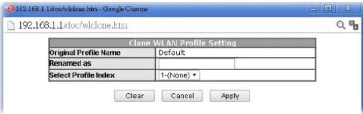 Third, choose the profile index to accept the settings from the original profile. Forth, type a new name in the field of Renamed as. Last, click Apply to save the settings on this dialog.The new profile has been created with the settings coming from the original profile. Third, choose the profile index to accept the settings from the original profile. Forth, type a new name in the field of Renamed as. Last, click Apply to save the settings on this dialog.The new profile has been created with the settings coming from the original profile. |
| To AP Click it to apply the | selected wireless profile to the specified Access Point.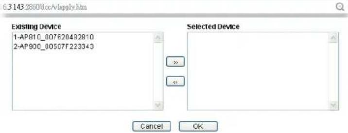 Simply choose the device you want from Existing Device field.Click >> to move the device to Selected Device field. Then,click OK.The selected WLAN profile will be applied to the selectedaccess point immediately. Later the access point will reboot. Simply choose the device you want from Existing Device field.Click >> to move the device to Selected Device field. Then,click OK.The selected WLAN profile will be applied to the selectedaccess point immediately. Later the access point will reboot. |
| To Local WLAN Profile configured in this page is specified for VigorAPconnected to Vigor router.If required, these settings also can be applied to Vigor router.Select and check one of wireless profiles and click this buttonto apply the settings onto the WI-Fi wireless settingsconfigured for such Vigor router. | |
How to edit the wireless LAN profile?
- Select the WLAN profile (index number 1 to 5) you want to edit.
- Click the index number link to display the following page.
Central Management >> AP >> WLAN Profile
WLAN Profile Edit
| Device Settings | ||
| Profile Name | Default | Auto Provision |
| Administrator | admin | |
| Password | ...... | |
| 2nd Subnet | Enable Disable | |
| Management VLAN | Enable Management VLAN:LAN-A VLAN ID 0 (0 ~ 4095)LAN-B VLAN ID 0 (0 ~ 4095) | |
WLAN General Setting
| 2.4GHz | 5GHz | 5GHz-2 | |
| Wireless LAN | ● Enable ○ Disable | ||
| Limit Client | □ Enable 64 (3 ~ 128, default: 64) | ||
| Operation Mode | AP √ | ||
| 2.4G Mode | Mixed(11b+11g+11n) √ | ||
| 2.4G Channel | 2462MHz (Channel 11) √ | ||
| Airtime Fairness | □ Enable Airtime Fairness:Triggering Client Number 2 (2 ~ 128, default: 2) | ||
| Band Steering | □ Enable Band Steering:Check Time for WLAN Client 5G Cap. 15 seconds (1 ~ 60, default: 15) | ||
| □ Minimum Basic Rate 1 √ Mbps | |||

Info
The function of Auto Provision is available for the default WLAN profile.
- After finished the general settings configuration, click Next to open the following page for 2.4G wireless security settings.
Central Management >> AP >> WLAN Profile
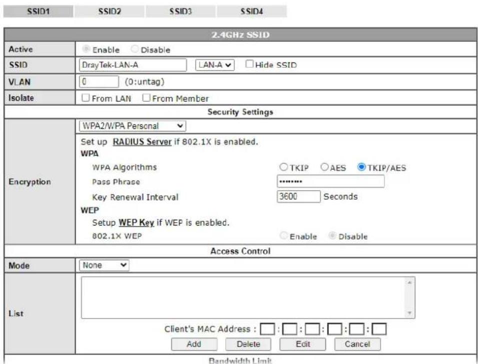
text_image
SSID1 SSID2 SSID3 SSID4 2.4GHz SSID Active Enable Disable SSID DrayTek-LAN-A LAN-A ▼ Hide SSID VLAN 0 (0:untag) Isolate From LAN From Member Security Settings Encryption WPA2/WPA Personal Set up RADIUS Server if 802.1X is enabled. WPA WPA Algorithms ○TKIP ○AES ●TKIP/AES Pass Phrase --------------------- Key Renewal Interval 3600 Seconds WEP Setup WEP Key if WEP is enabled. 802.1X WEP Enable ●Disable Access Control Mode None List Client's MAC Address : □:□:□:□:□: Add Delete Edit Cancel Bandwidth Limit- After finished the above web page configuration, click Next to open the following page for 5G wireless security settings.
Central Management >> AP >> WLAN Profile
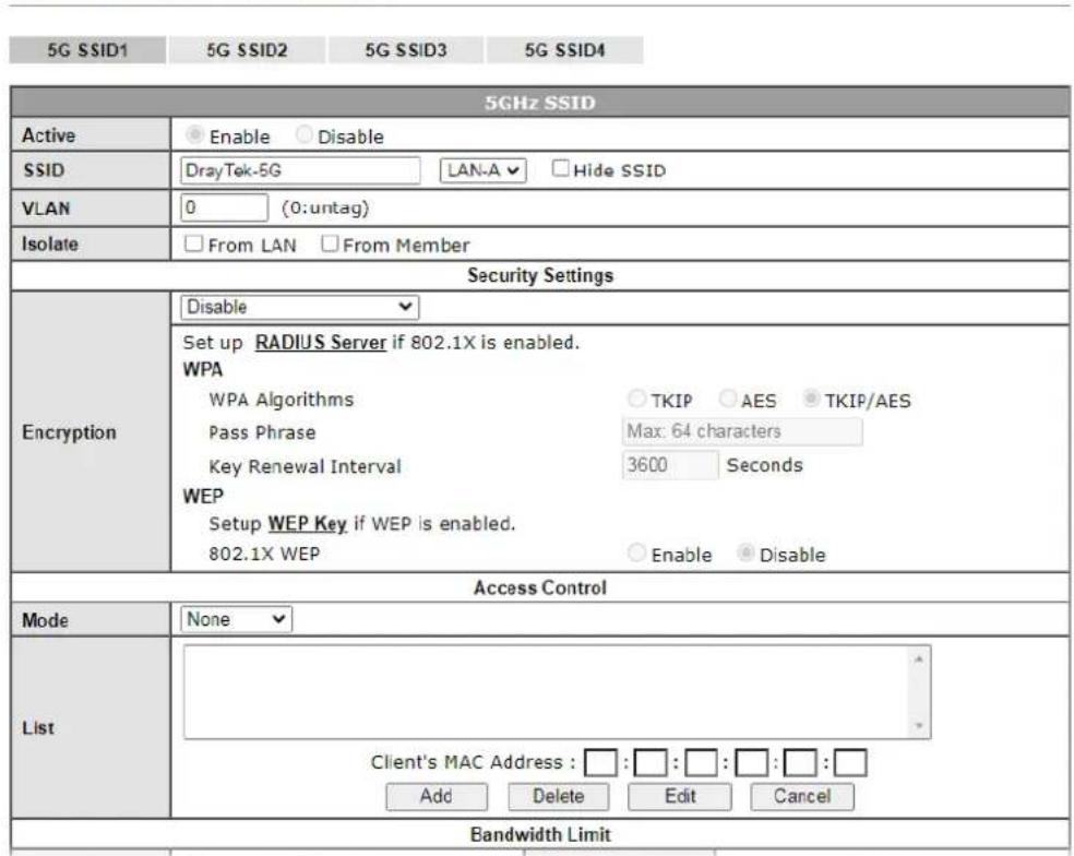
text_image
5G SSID1 5G SSID2 5G SSID3 5G SSID4 5GHz SSID Active Enable Disable SSID DrayTek-5G LAN-A ▼ Hide SSID VLAN 0 (0:untag) Isolate From LAN From Member Security Settings Encryption Disable Set up RADIUS Server if 802.1X is enabled. WPA WPA Algorithms ○ TKIP ○ AES ● TKIP/AES Pass Phrase Max: 64 characters Key Renewal Interval 3600 Seconds WEP Setup WEP Key if WEP is enabled. 802.1X WEP ○ Enable ● Disable Access Control Mode None List Client's MAC Address : □:□:□:□:□:□ Add Delete Edit Cancel Bandwidth Limit- When you finished the above web page configuration, click Finish to exit and return to the first page. The modified WLAN profile will be shown on the web page.
Central Management >> AP >> WLAN Profile
Set to Factory Default
| Profile | Name | Main SSID | Security | Multi-SSID | WLAN ACL | Rate Ctrl | Clone | To AP | To Local |
| 1 | Default | DrayTek-LAN-A | WPA+WPA2/PSK | Enable | None | None | |||
| 2 | 123 | DrayTek | Disable | Disable | None | None | x | ||
| 3 | --- | --- | --- | --- | --- | --- | --- | --- | - |
| 4 | --- | --- | --- | --- | --- | --- | --- | --- | - |
| 5 | --- | --- | --- | --- | --- | --- | --- | --- | - |
VI-3-4 AP Maintenance
Vigor router can execute configuration backup, configuration restoration, firmware upgrade and remote reboot for the APs managed by the router. It is very convenient for the administrator to process maintenance without accessing into the web user interface of the access point.

Info
Config Backup can be performed to one AP at one time. Others functions (e.g., Config Restore, Firmware Upgrade, Remote Reboot can be performed to more than one AP at one time by using VigorLTE 200.
Central Management >> AP >> AP Maintenance
AP Maintenance
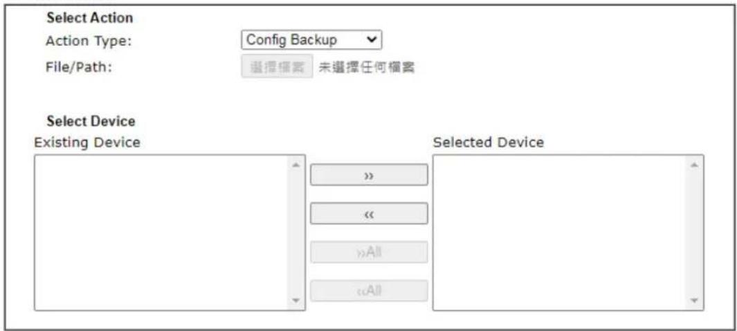
text_image
Select Action Action Type: Config Backup File/Path: 选择搜索 未选择任何搜索 Select Device Existing Device Selected Device
Available settings are explained as follows:
| Item | Description |
| Action There are four actions provided by Vigor router to manage the access points. | 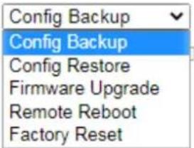 Vigor router can backup the configuration of the selected AP, restore the configuration for the selected AP, perform the firmware upgrade of the selected AP, reboot the selected AP remotely and perform the factory reset for the selected AP. Vigor router can backup the configuration of the selected AP, restore the configuration for the selected AP, perform the firmware upgrade of the selected AP, reboot the selected AP remotely and perform the factory reset for the selected AP. |
| File/Path | Specify the file and the path which will be used to perform Config Restore or Firmware Upgrade. |
| Select Device | Display all the available access points managed by Vigorrouter. Simply click << or >> to move the device(s) between Select Device and Selected Device areas. |
| Selected Device | Display the access points that will be applied by such function after clicking OK. |
After finishing all the settings here, please click OK to perform the action.
VI-3-5 Traffic Graph
Click Traffic Graph to open the web page. Choose one of the managed Access Points, LAN-A or LAN-B, daily or weekly for viewing data transmission chart. Click Refresh to renew the graph at any time.
Central Management >> AP >> Traffic Graph
Enable
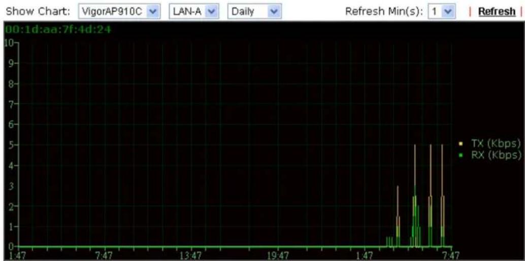
bar
| Time | TX (Kbps) | RX (Kbps) | |--------|-----------|-----------| | 1:47 | 0 | 0 | | 7:47 | 0 | 0 | | 13:47 | 0 | 0 | | 19:47 | 0 | 0 | | 1:47 | 0 | 0 | | 7:47 | 2.5 | 2.0 |Note:
Enabling/Disabling AP Traffic Graph will also Enable/Disable the External Devices Function.
The horizontal axis represents time; the vertical axis represents the transmission rate (in kbps).

Info
Enabling/ Disabling such function will also enable/ disable the External Devices function.
VI-3-6 Temperature Sensor
Many VigorAPs and Vigor routers can be installed with temperature sensor. If VigorAP (e.g., VigorAP 910C) is managed under Vigor router, then Vigor router can obtain the temperature change graph of the USB temperature sensor installed onto VigorAP.
This page displays data including current temperature, maximum temperature, minimum temperature and average temperature.
Central Management >> AP >> Temperature Sensor
text_image
Temperature Unit Celsius Fahrenheit | Refresh | Current AverageNote:
Only browser supporting HTML5 can display temperature sensor correctly.
VI-3-7 Event Log
Time and event log for all of the APs managed by Vigor router will be shown on this page. It is useful for troubleshooting if required.
Central AP Management >> Event Log

text_image
All Event Log Clear | Refresh | Time APM Event Log 2000-01-01 00:00:24 [APM] [VigorAP900_01daa9e2b38] Apply Rogue AP Detection settings 2000-01-01 00:00:24 [APM] [VigorAP900_01daa9e2b38] Apply Load Balance settings 2000-01-01 00:00:26 [APM] [VigorAP900_01daa9e2b38] Apply Rogue AP Detection settings S 2000-01-01 00:00:29 [APM] [VigorAP900_01daa9e2b38] Query AP status 2000-01-01 00:00:29 [APM] [VigorAP900_01daa9e2b38] Apply Load Balance settings success 2000-01-01 00:00:35 [APM] [VigorAP900_01daa9e2b38] Query AP statusVI-3-8 Total Traffic
Such page will display the total traffic of data receiving and data transmitting for VigorAPs managed by Vigor router.
Central AP Management >> Total Traffic
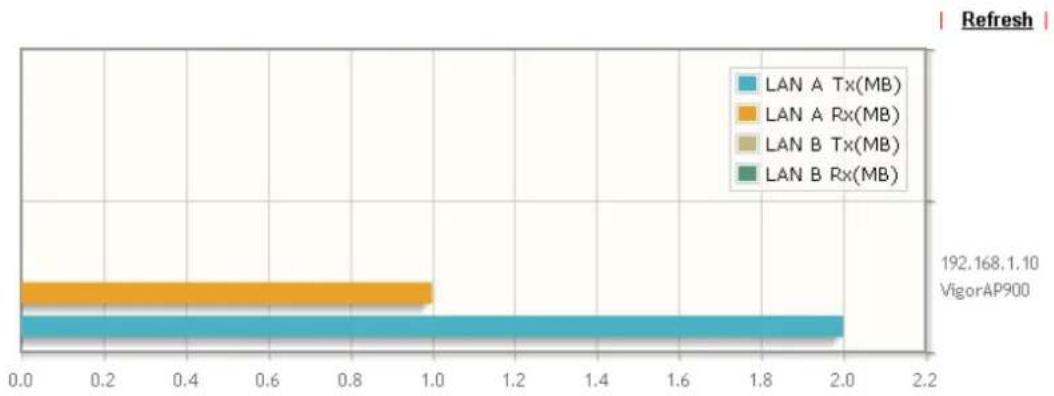
bar
| Category | Value | | :--- | :--- | | LAN A Tx(MB) | 2.0 | | LAN A Rx(MB) | 1.0 | | LAN B Tx(MB) | 0.0 | | LAN B Rx(MB) | 0.0 | | Total | 192.168 | | VigorAP900 | 1.10 |Note: Only browser supporting HTML5 can display Total Traffic correctly.
VI-3-9 Station Number
The total number of the wireless clients will be shown on this page.
Central Management >> AP >> Station Number
Hourly Records(2 Hours)
Station Number
line
| Time | Value | |---|---| | 23:00 | 1.0 | | 23:04 | 1.0 | | 23:11 | 1.0 | | 23:16 | 1.0 | | 23:23 | 1.0 | | 23:28 | 1.0 | | 23:34 | 1.0 | | 23:40 | 1.0 | | 23:46 | 1.0 | | 23:52 | 1.0 | | 23:58 | 1.0 | | 00:00 | 1.0 | | 00:06 | 1.0 | | 00:12 | 1.0 | | 00:18 | 1.0 | | 00:24 | 1.0 | | 00:30 | 1.0 | | 00:36 | 1.0 | | 00:42 | 1.0 | | 00:48 | 1.0 | | 00:54 | 1.0 | | 00:60 | 1.0 | | 00:66 | 1.0 | | 5:00 | 1.0 | | 5:06 | 1.0 | | 5:12 | 1.0 | | 5:18 | 1.0 | | 5:24 | 1.0 | | 5:30 | 1.0 | | 5:36 | 1.0 | | 5:42 | 1.0 | | 5:48 | 1.0 | | 5:54 | 1.0 | | 5:60 | 1.0 | | 5:66 | 1.0 | | 5:72 | 1.0 | | 5:78 | 1.0 | | 5:84 | 1.0 | | 5:90 | 1.0 | | 5:96 | 1.0 | | 6:02 | 1.0 | | 6:08 | 1.0 | | 6:14 | 1.0 | | 6:20 | 1.0 | | 6:26 | 1.0 | | 6:32 | 1.0 | | 6:38 | 1.0 | | 6:44 | 1.0 | | 6:50 | 1.0 | | 6:56 | 1.0 | The chart displays a single data series with values ranging from approximately -1.0 to +1.0, but specific numerical labels are not provided in the image.Refresh
Time
Note:
Only browser supporting HTML5 can display Station Number correctly.
VI-3-10 Load Balance
The parameters configured for Load Balance can help to distribute the traffic for all of the access points registered to Vigor router. Thus, the bandwidth will not be occupied by certain access points.
Central Management >> AP >> Load Balance
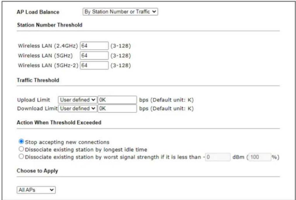
text_image
AP Load Balance By Station Number or Traffic Station Number Threshold Wireless LAN (2.4GHz) 64 (3-128) Wireless LAN (5GHz) 64 (3-128) Wireless LAN (5GHz-2) 64 (3-128) Traffic Threshold Upload Limit User defined √ 0K bps (Default unit: K) Download Limit User defined √ 0K bps (Default unit: K) Action When Threshold Exceeded Stop accepting new connections Dissociate existing station by longest idle time Dissociate existing station by worst signal strength if it is less than -0 dBm (100 %) Choose to Apply All APsNote:
The maximum station number of Wireless LAN (2.4GHz) will be applied to both Wireless LAN (2.4GHz) and Wireless LAN (5GHz) if the firmware version of AP900 is less than or equal to 1.1.4.1.

Available settings are explained as follows:
| Item | Description |
| AP Load Balance It is used | to determine the operation mode when the system detects overload between access points.Disable - Disable the function of AP load balance.By Station Number -The operation of load balance will be executed based on the station number configured in this page. It is used to limit the allowed number for the station connecting to the access point. The purpose is to prevent lots of stations connecting to access point at the same time and causing traffic unbalanced. Please define the required station number for WLAN (2.4GHz) and WLAN (5GHz) separately.By Traffic - The operation of load balance will executed according to the traffic configuration in this page.By Station Number or Traffic - The operation of load balance will be executed based on the station number or the traffic configuration. |
| Station Number Threshold | Set the number of stations as a threshold to activate AP load balance. |
| Traffic Threshold Upload | Limit -Use the drop down list to specify the trafficlimit for uploading.Download Limit - Use the drop down list to specify the traffic limit for downloading. |
| Action When Threshold Exceeded | Stop accepting new connections - When the number of stations or the traffic reaches the threshold defined in this web page, Vigor router will stop any new connection asked by other access point.Dissociate existing station by longest idel time - When the access point is overload (e.g., reaching the limit of station number or limit of network traffic), it will terminate the network connection of the client's station which is idle for a longest time.Dissociate existing station by worst signal strength if it is less than - When the access point is overload (e.g., reaching the limit of station number or limit of network traffic), it will terminate the network connection of the client's station with the weakest signal. |
Choose to Apply The settings configured for Load Balance can be applied to all of AP devices or selected AP devices.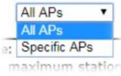 | |
After finishing all the settings here, please click OK to save the configuration.
VI-3-11 Function Support List
Central AP Management >> Function Support List
| Model Name | AP710 | AP800 | AP810 | AP900 | AP902 | AP910C |
| FW Version | 1.2.0 | 1.1.6 | 1.1.6.1 | 1.1.7 | 1.1.7 | 1.1.6 |
| Register | ||||||
| DHCP | ● | ● | ● | ● | ● | ● |
| Static IP | ● | ● | ● | ● | ● | ● |
| Profile | ||||||
| 2.4GHz | ● | ● | ● | ● | ● | ● |
| 5GHz | (with N65) | ● | ● | ● | ||
| AP Mode | ● | ● | ● | ● | ● | ● |
| Auto Provision | ● | ● | ● | ● | ● | ● |
| WLAN Enable/Disable | ● | ● | ● | ● | ● | ● |
| Limit Client | ● | ● | ● | ● | ● | |
| Airtime Fairness | ● | ● | ● | ● | ● | |
| Band Steering | ● | ● | ● | |||
| Fast Roaming | ● | ● | ● | ● | ● | |
| Access Control List | ● | ● | ● | ● | ● | ● |
| Bandwidth Limit | ● | ● | ● | ● | ● | ● |
| Centralized AP Management | ||||||
| AP Maintenance | ● | ● | ● | ● | ● | |
| Traffic Graph | ● | ● | ● | ● | ● | ● |
| Event Log | ● | ● | ● | ● | ● | |
| Total Traffic | ● | ● | ● | ● | ● | |
| Station Number | ● | ● | ● | ● | ● | |
| Load Balance | ● | ● | ● | ● | ● | |
This page is left blank.
Part VII Others

Objects Settings
Define objects such as IP address, service type, keyword, file extension and others. These pre-defined objects can be applied in CSM.
VII-1 Objects Settings
Define objects such as IP address, service type, keyword, file extension and others. These pre-defined objects can be applied in CSM.
Web User Interface
Objects Setting
IP Object
IP Group
IPv6 Object
IPv6 Group
Service Type Object
Service Type Group
Keyword Object
Keyword Group
File Extension Object
SMS/Mail Service Object
Notification Object
String Object
VII-1-1 IP Object
For IPs in a range and service ports in a limited range usually will be applied in configuring router's settings, therefore we can define them with objects and bind them with groups for using conveniently. Later, we can select that object/group that can apply it. For example, all the IPs in the same department can be defined with an IP object (a range of IP address).
You can set up to 192 sets of IP Objects with different conditions.
Create from ARP Table
Create from Routing Table
IP Object Profiles:
Note:
For better compatibility, it's suggested to edit IP Objets with the provided default CSV template.
Available settings are explained as follows:
| Item | Description |
| View Use the drop down list | to choose a type (Single Address,Range Address, Subnet Address, Mac Address or all) that IP object with the selected type will be shown on this page. |
| Set to Factory Default Clear | all profiles. |
| Search Type a string of the | IP object that you want to search. |
| Index Display the profile number that you can configure. | |
| Name Display the name of the object profile. | |
| Address Display the IP address configured for the object profile. | |
| Export IP Object Usually, the | IP objects can be created one by one throughthe web page of Objects>>IP Object. However, to a userwho wants to save more time in bulk creating IP objects, aquick method is offered by Vigor router to modify the IPobjects with a single file, a CSV file.All of the IP objects (or the template) can be exported as afile by clicking Download. Then the user can open the CSVfile through Microsoft Excel and modify all the IP objects atthe same time.Backup the current IP Objects with a CSV file - Click it tobackup current IP objecsts as a CSV file. Such file can berestored for future use.Download the default CSV template to edit - After clicking it, press Download to store the default CSM template (a table without any input data) to your hard disk.Download - Download the CSV file from Vigor router and store in your hard disk. |
| Restore IP Object | Select - Click it to specify a predefined CSV file.Restore - Import the selected CSV file onto Vigor router. |
To set a new profile, please do the steps listed below:
-
Click the number (e.g., #1) under Index column for configuration in details.
-
The configuration page will be shown as follows:
Objects Setting >> IP Object
Profile Index : 1
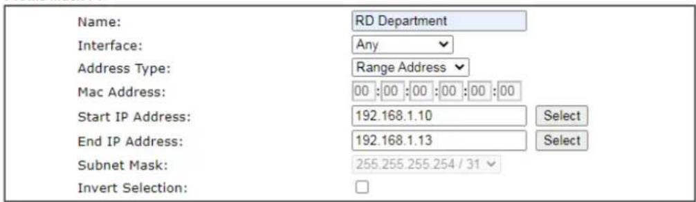
text_image
Name: RD Department Interface: Any Address Type: Range Address Mac Address: 00 :00 :00 :00 :00 :00 Start IP Address: 192.168.1.10 Select End IP Address: 192.168.1.13 Select Subnet Mask: 255.255.255.254 / 31 Invert Selection: □Next >>

Available settings are explained as follows:
| Item | Description |
| Name Type a name for | this profile. Maximum 15 characters are allowed. |
| Interface Choose a proper interface. | |
| Address Type Determine the address type for the IP address.Select Single Address if this object contains one IP address only.Select Range Address if this object contains several IPs within a range.Select Subnet Address if this object contains one subnet for IP address.Select Any Address if this object contains any IP address.Select Mac Address if this object contains Mac address. | |
| MAC Address Enter the MAC address of the network card which will be controlled. | |
| Start IP Address Enter the start IP address for Single Address type. | |
| End IP Address Enter the end IP address if the Range Address type is selected. | |
| Subnet Mask Enter the subnet mask if the Subnet Address type is selected. | |
| Invert Selection If it is checked, all the IP addresses except the ones listed above will be applied later while it is chosen. | |
- After finishing all the settings here, please click OK to save the configuration. Below is an example of IP objects settings.
Objects Setting >> IP Object
IP Object Profiles:
| Index | Name | Index |
| 1. | RD Department | 17. |
| 2. | Financial Dept | 18. |
| 3. | HR Department | 19. |
| 4. | 20. | |
| 5. | 21. | |
| 6. | 22. |
VII-1-2 IP Group
This page allows you to bind several IP objects into one IP group.
Objects Setting >> IP Group
Available settings are explained as follows:
| Item | Description |
| Set to Factory Default Clear all profiles. | |
| Index Display the profile number that you can configure. | |
| Name Display the name of the group profile. | |
To set a new profile, please do the steps listed below:
- Click the number (e.g., #1) under Index column for configuration in details.
- The configuration page will be shown as follows:
Objects Setting >> IP Group
Profile Index : 1
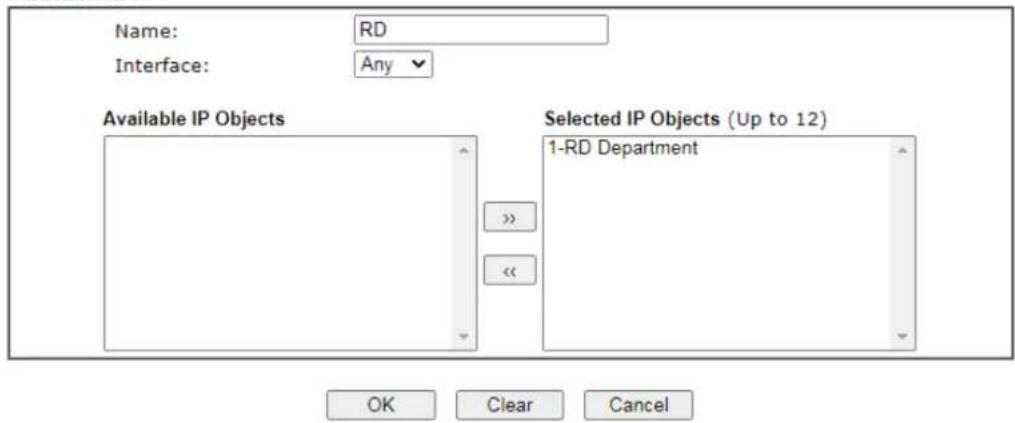
text_image
Name: RD Interface: Any Available IP Objects Selected IP Objects (Up to 12) 1-RD Department OK Clear CancelAvailable settings are explained as follows:
| Item | Description |
| Name Type a name for | this profile. Maximum 15 characters are allowed. |
| Interface Choose WAN, | LAN or Any to display all the available IP objects with the specified interface. |
| Available IP Objects All | the available IP objects with the specified interface chosen above will be shown in this box. |
| Selected IP Objects | Click >> button to add the selected IP objects in this box. |
- After finishing all the settings here, please click OK to save the configuration.
VII-1-3 IPv6 Object
You can set up to 64 sets of IPv6 Objects with different conditions.
Objects Setting >> IPv6 Object
Available settings are explained as follows:
| Item | Description |
| Set to Factory Default Clear all profiles. | |
| Index Display the profile number that you can configure. | |
| Name Display the name of the object profile. | |
To set a new profile, please do the steps listed below:
-
Click the number (e.g., #1) under Index column for configuration in details.
-
The configuration page will be shown as follows:
Objects Setting >> IPv6 Object
Profile Index : 1
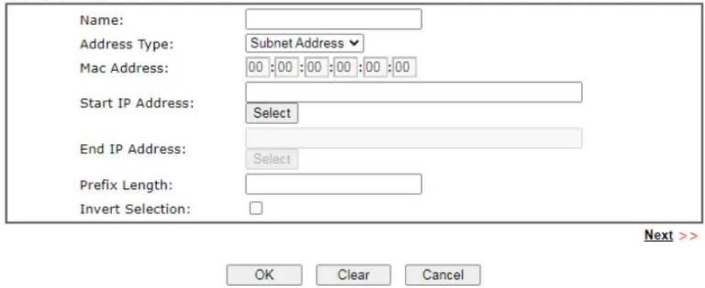
text_image
Name: Address Type: Subnet Address Mac Address: 00:00:00:00:00:00 Start IP Address: Select End IP Address: Select Prefix Length: Invert Selection: OK Clear Cancel Next >>Available settings are explained as follows:
| Item | Description |
| Name Type a name for | this profile. Maximum 15 characters are allowed. |
| Address Type Determine | the address type for the IPv6 address.Select Single Address if this object contains one IPv6 address only.Select Range Address if this object contains several IPv6s within a range.Select Subnet Address if this object contains one subnet for IPv6 address.Select Any Address if this object contains any IPv6 address.Select Mac Address if this object contains Mac address. |
| Mac Address Enter the | MAC address of the network card which will be controlled. |
| Start IP Address Enter | the start IP address for Single Address type. |
| End IP Address Enter the | the end IP address if the Range Address type is selected. |
| Prefix Length | Enter the number (e.g., 64) for the prefix length of IPv6 address. |
| Invert Selection If it is | checked, all the IPv6 addresses except the ones listed above will be applied later while it is chosen. |
- After finishing all the settings, please click OK to save the configuration.
VII-1-4 IPv6 Group
This page allows you to bind several IPv6 objects into one IPv6 group.
Objects Setting >> IPv6 Group
Available settings are explained as follows:
| Item | Description |
| Set to Factory Default Clear all profiles. | |
| Index Display the profile number that you can configure. | |
| Name Display the name of the group profile. | |
To set a new profile, please do the steps listed below:
- Click the number (e.g., #1) under Index column for configuration in details.
- The configuration page will be shown as follows:
Objects Setting >> IPv6 Group
Profile Index : 1
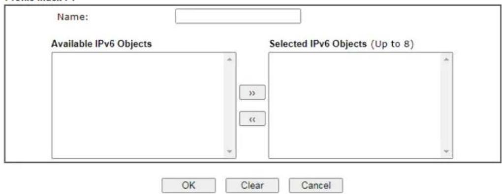
text_image
Name: Available IPv6 Objects Selected IPv6 Objects (Up to 8) OK Clear CancelAvailable settings are explained as follows:
| Item | Description |
| Name Type a name for | this profile. Maximum 15 characters are allowed. |
| Available IPv6 Objects | All the available IPv6 objects with the specified interface chosen above will be shown in this box. |
| Selected IPv6 Objects | Click >> button to add the selected IPv6 objects in this box. |
- After finishing all the settings, please click OK to save the configuration.
VII-1-5 Service Type Object
You can set up to 96 sets of Service Type Objects with different conditions.
Objects Setting >> Service Type Object
Available settings are explained as follows:
| Item | Description |
| Set to Factory Default Clear | all profiles. |
| Index | Display the profile number that you can configure. |
| Name Display the name of the object profile. | |
To set a new profile, please do the steps listed below:
-
Click the number (e.g., #1) under Index column for configuration in details.
-
The configuration page will be shown as follows:
Objects Setting >> Service Type Object Setup
Profile Index : 1
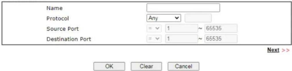
text_image
Name Protocol Any Source Port = 1 ~ 65535 Destination Port = 1 ~ 65535 Next >> OK Clear CancelAvailable settings are explained as follows:
| Item | Description |
| Name Type a name for | this profile. Maximum 15 characters are allowed. |
| Protocol Specify the protocol(s) which this profile will apply to. | 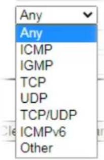 |
| Source/Destination Port | Source Port and the Destination Port columns are available for TCP/UDP protocol. It can be ignored for other protocols. The filter rule will filter out any port number.(=)- when the first and last value are the same, it indicates one port; when the first and last values are different, it indicates a range for the port and available for this profile.(!=)- when the first and last value are the same, it indicates all the ports except the port defined here; when the first and last values are different, it indicates that all the ports except the range defined here are available for this service type.(>) - the port number greater than this value is available.(<)- the port number less than this value is available for this profile. |
- After finishing all the settings, please click OK to save the configuration.
Objects Setting >> Service Type Object
Service Type Object Profiles:
| Index | Name | Inde |
| 1. | www | 17 |
| 2. | SIP | 18 |
| 3. | 19 | |
| 4. | 20 |
VII-1-6 Service Type Group
This page allows you to bind several service types into one group.
Objects Setting >> Service Type Group
Available settings are explained as follows:
| Item | Description |
| Set to Factory Default Clear all profiles. | |
| Index Display the profile number that you can configure. | |
| Name Display the name of the group profile. | |
To set a new profile, please do the steps listed below:
-
Click the number (e.g., #1) under Group column for configuration in details.
-
The configuration page will be shown as follows:
Objects Setting >> Service Type Group Setup
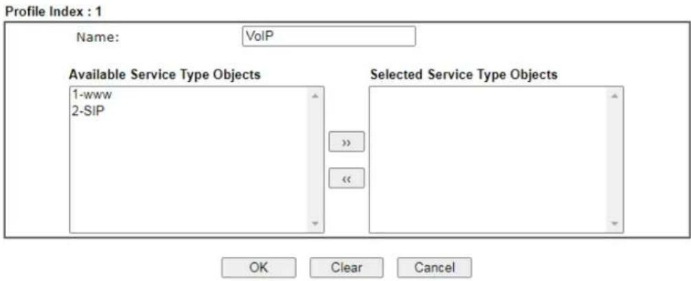
text_image
Profile Index : 1 Name: VoIP Available Service Type Objects 1-www 2-SIP Selected Service Type Objects OK Clear CancelAvailable settings are explained as follows:
| Item | Description |
| Name Type a name for | this profile. Maximum 15 characters are allowed. |
| Available Service Type Objects | All the available service objects that you have added on Objects Setting>>Service Type Object will be shown in this box. |
| Selected Service Type Objects | Click >> button to add the selected IP objects in this box. |
- After finishing all the settings, please click OK to save the configuration.
VII-1-7 Keyword Object
You can set 200 keyword object profiles for choosing as black / white list in CSM >>URL Web Content Filter Profile.
Objects Setting >> Keyword Object
Available settings are explained as follows:
| Item | Description |
| Set to Factory Default Clear all profiles. | |
| Index Display the profile number that you can configure. | |
| Name Display the name of the object profile. | |
To set a new profile, please do the steps listed below:
-
Click the number (e.g., #1) under Index column for configuration in details.
-
The configuration page will be shown as follows:
Objects Setting >> Keyword Object Setup
Profile Index : 1
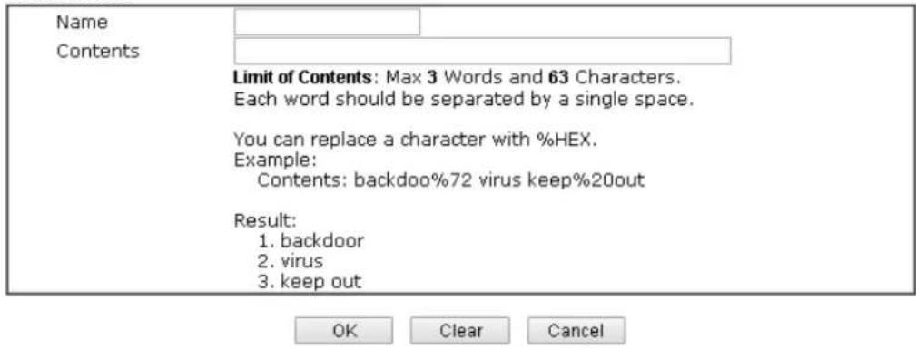
text_image
Name Contents Limit of Contents: Max 3 Words and 63 Characters. Each word should be separated by a single space. You can replace a character with %HEX. Example: Contents: backdoo%72 virus keep%20out Result: 1. backdoor 2. virus 3. keep out OK Clear CancelAvailable settings are explained as follows:
| Item | Description |
| Name Type a name for | this profile, e.g., game. Maximum 15 characters are allowed. |
| Contents Enter the content for such profile. For example, type gambling as Contents. When you browse the webpage, the page with gambling information will be watched out and be passed/ blocked based on the configuration on Firewall settings. | |
- After finishing all the settings, please click OK to save the configuration.
VII-1-8 Keyword Group
This page allows you to bind several keyword objects into one group. The keyword groups set here will be chosen as black / white list in CSM >>URL / Web Content Filter Profile.
Objects Setting >> Keyword Group
Available settings are explained as follows:
| Item | Description |
| Set to Factory Default Clear all profiles. | |
| Index Display the profile number that you can configure. | |
| Name Display the name of the group profile. | |
To set a new profile, please do the steps listed below:
-
Click the number (e.g., #1) under Index column for configuration in details.
-
The configuration page will be shown as follows:
Objects Setting >> Keyword Group Setup
Profile Index : 1
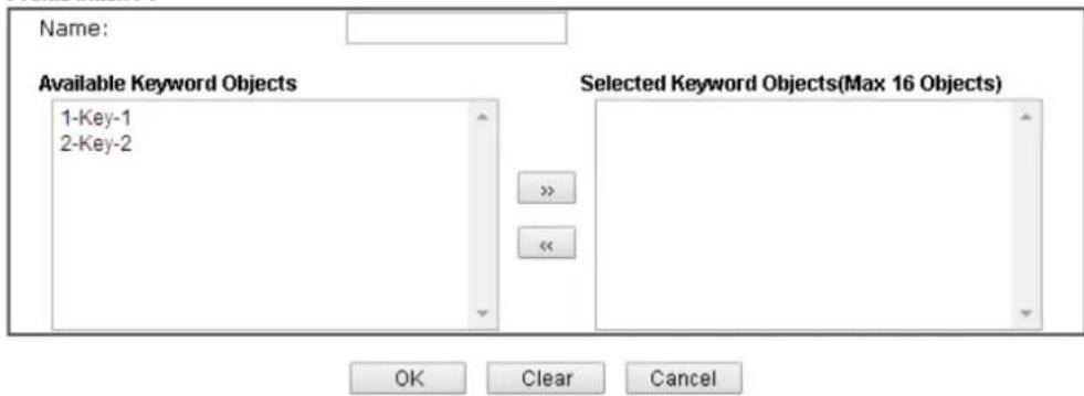
text_image
Name: Available Keyword Objects 1-Key-1 2-Key-2 Selected Keyword Objects(Max 16 Objects) OK Clear CancelAvailable settings are explained as follows:
| Item | Description |
| Name Type a name for this group. Maximum 15 characters are allowed. | |
| Available Keyword Objects | You can gather keyword objects from Keyword Object page within one keyword group. All the available Keyword objects that you have created will be shown in this box. |
| Selected Keyword Objects | Click >> button to add the selected Keyword objects in this box. |
- After finishing all the settings, please click OK to save the configuration.
VII-1-9 File Extension Object
This page allows you to set eight profiles which will be applied in CSM>>URL Content Filter. All the files with the extension names specified in these profiles will be processed according to the chosen action.
Objects Setting >> File Extension Object
| Profile | Name | Profile | Name |
| 1. | 5. | ||
| 2. | 6. | ||
| 3. | 7. | ||
| 4. | 8. |
Available settings are explained as follows:
| Item | Description |
| Set to Factory Default Clear | all profiles. |
| Profile | Display the profile number that you can configure. |
| Name Display the name of the object profile. | |
To set a new profile, please do the steps listed below:
- Click the number (e.g., #1) under Profile column for configuration in details.
- The configuration page will be shown as follows:
Objects Setting >> File Extension Object Setup
| Categories | File Extensions | ||||||
| Image Select All Clear All | . bmp .dib .gif .jpeg .jpg .jpg2 .jp2 .pct .pcx .pic .pict .png .tif .tiff | ||||||
| Video Select All Clear All | .asf .avi .mov .mpe .mpeg .mpg .mp4 .qt .rm .wmv .3gp .3gpp .3gpp2 .3g2 .flv .swf | ||||||
| Audio Select All Clear All | .aac .aiff .au .mp3 .m4a .m4p .agg .ra .ram .vox .wav .wma | ||||||
| Java Select All Clear All | .class .jad .jar .jav .java .jcm .js .jse .jsp .jtk | ||||||
Available settings are explained as follows:
| Item | Description |
| Profile Name Type a name for this profile. The maximum length of the name you can set is 7 characters. | |
- Type a name for such profile and check all the items of file extension that will be processed in the router. Finally, click OK to save this profile.
VII-1-10 SMS Service Object
This page allows you to set ten profiles which will be applied in Application>>SMS Service Object.
Objects Setting >> SMS Service Object
| SMS Provider | Set to Factory Default | |
| Index | Profile Name | SMS Provider |
| 1. | ||
| 2. | ||
| 3. | ||
| 4. | ||
| 5. | ||
| 6. | ||
| 7. | ||
| 8. | ||
| 9. | Custom 1 | |
| 10. | Custom 2 | |
Each item is explained as follows:
| Item | Description |
| Set to Factory Default Clear | all of the settings and return to factory default settings. |
| Index Display the profile number that you can configure. | |
| Profile Name Display the name for such SMS profile. | |
| SMS Provider Display the service provider which offers SMS service. | |
To set a new profile, please do the steps listed below:
-
Click the number (e.g., #1) under Index column for configuration in details.
-
The configuration page will be shown as follows:
Objects Setting >> SMS Service Object
Profile Index: 1
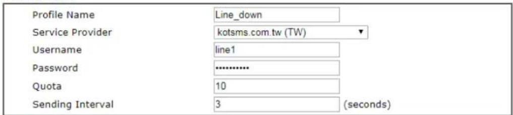
text_image
Profile Name Service Provider Username Password Quota Sending Interval Line_down kotsms.com.tw (TW) line1 .......... 10 3 (seconds)Note:
- Only one message can be sent during the "Sending Interval" time.
- If the "Sending Interval" was set to 0, there will be no limitation.

Available settings are explained as follows:
| Item | Description |
| Profile Name Type a name for such SMS profile. The maximum length of the name you can set is 31 characters. | |
| Service Provider | Use the drop down list to specify the service provider which offers SMS service.kotsms.com.tw (TW)kotsms.com.tw (TW)textmarketer.co.uk (UK)messagemedia.co.uk (UK)bulksms.com (INT)bulksms.co.uk (UK)bulksms.2way.co.za (ZA)bulksms.com.es (ES)usa.bulksms.com (US)bulksms.de (DE)www.pswin.com (EU)www.messagebird.com (EU)www.lusosms.com (EU)www.vibeactivemedia.com (UK)www.sms.sg (SG)rest.esms.vnVigor Router SMS GatewayLocal SMS Service (LTE) |
| Username | Type a user name that the sender can use to register to selected SMS provider.The maximum length of the name you can set is 31 characters. |
| Password Type a password that the sender can use to register to selected SMS provider.The maximum length of the password you can set is 31 characters. | |
| Quota Enter the number of the credit that you purchase from the service provider chosen above.Note that one credit equals to one SMS text message on the standard route. | |
| Sending Interval To avoid quota being exhausted soon, type time interval for sending the SMS. | |
- After finishing all the settings here, please click OK to save the configuration.
Objects Setting >> SMS Service Object
| SMS Provider | Set to Factory_Default | |
| Index | Profile Name | SMS Provider |
| 1. | Line_down | kotsms.com.tw (TW) |
| 2. | ||
| 3. | ||
| 4. | ||
| 5. | ||
| 6. | ||
| 7. | ||
| 8. | ||
| 9. | Custom 1 | |
| 10. | Custom 2 | |
Customized SMS Service
Vigor router offers several SMS service provider to offer the SMS service. However, if your service provider cannot be found from the service provider list, simply use Index 9 and Index 10 to make customized SMS service. The profile name for Index 9 and Index 10 are fixed.
Objects Setting >> SMS Service Object
| SMS Provider | Set to Factory Default | |
| Index | Profile Name | SMS Provider |
| 1. | ||
| 2. | ||
| 3. | ||
| 4. | ||
| 5. | ||
| 6. | ||
| 7. | ||
| 8. | ||
| 9. | Custom 1 | |
| 10. | Custom 2 | |
You can click the number (e.g., #9) under Index column for configuration in details.
Objects Setting >> SMS Service Object
Profile Index: 9
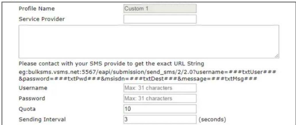
text_image
Profile Name Custom 1 Service Provider Please contact with your SMS provide to get the exact URL String eg:bulksms.vsms.net:5567/eapi/submission/send_sms/2/2.0?username=###txtUser### &password=###txtPwd###&msisdn=###txtDest###&message=###txtMsg### Username Max: 31 characters Password Max: 31 characters Quota 10 Sending Interval 3 (seconds)Note:
- Only one message can be sent during the "Sending Interval" time.
- If the "Sending Interval" was set to 0, there will be no limitation.
OK Clear Cancel
Available settings are explained as follows:
| Item | Description |
| Profile Name Display the name of this profile. It cannot be modified. | |
| Service Provider Enter the website of the service provider.Enter the URL string in the box under the filed of Service Provider. You have to contact your SMS provider to obtain the exact URL string. | |
| Username | Type a user name that the sender can use to register to selected SMS provider.The maximum length of the name you can set is 31characters. |
| Password Type a password that the sender can use to register to selected SMS provider.The maximum length of the password you can set is 31 characters. | |
| Quota | Enter the total number of the messages that the router will send out. |
| Sending Interval Enter the shortest time interval for the system to send SMS. | |
After finishing all the settings here, please click OK to save the configuration.
VII-1-11 Notification Object
This page allows you to set ten profiles which will be applied in Application>>SMS Alert Service.
You can set an object with different monitoring situation.
Object Settings >> Notification Object
| Index | Profile Name | Settings |
| 1. | ||
| 2. | ||
| 3. | ||
| 4. | ||
| 5. | ||
| 6. | ||
| 7. | ||
| 8. |
To set a new profile, please do the steps listed below:
- Open Object Setting>>Notification Object, and click the number (e.g., #1) under Index column for configuration in details.
Object Settings >> Notification Object
| Index | Profile Name |
| 1. | |
| 2. | |
| 3. | |
| 4. |
- The configuration page will be shown as follows:
Objects Setting >> Notification Object
Profile Index: 1
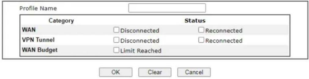
text_image
Profile Name Category Status WAN □ Disconnected □ Reconnected VPN Tunnel □ Disconnected □ Reconnected WAN Budget □ Limit Reached OK Clear CancelAvailable settings are explained as follows:
| Item | Description |
| Profile Name Type a name for such notification profile. The maximum length of the name you can set is 15 characters. | |
| Category Display the types that will be monitored. | |
| Status Display the status for the category. You can check the box to be monitored. | |
- After finishing all the settings here, please click OK to save the configuration.
Object Settings >> Notification Object
| Index | Profile Name | Settings |
| 1. | Notify_attack | WAN VPN |
| 2. | ||
| 3. |
VII-1-12 String Object
This page allows you to set string profiles which will be applied in route policy (domain name selection for destination) and etc.
Objects Setting >> String Object

text_image
10 strings per page | Set to Factory Default | AddAvailable settings are explained as follows:
| Item | Description |
| Add Click it to open the following page for adding a new string object. | 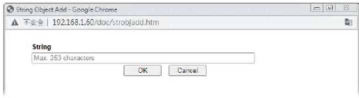 |
| Set to Factory Default Click it to clear all of the settings in this page. | |
| Index | Display the number link of the string profile. |
| String Display the string defined. | |
| Clear Choose the string that you want to remove. Then click this check box to delete the selected string. | |
Application Notes
A-1 How to Send a Notification to Specified Phone Number via SMS Service in WAN Disconnection
Follow the steps listed below:
-
Log into the web user interface of Vigor router.
-
Configure relational objects first. Open Object Settings>>SMS Server Object to get the following page.
Objects Setting >> SMS Service Object
| Index | Profile Name | SMS Provider |
| 1. | kotsms.com.tw (TW) | |
| 2. | ||
| 3. | ||
| 4. | ||
| 5. | ||
| 6. | ||
| 7. | ||
| 8. | ||
| 9. | Custom 1 | |
| 10. | Custom 2 |
Index 1 to Index 8 allows you to choose the built-in SMS service provider. If the SMS service provider is not on the list, you can configure Index 9 and Index 10 to add the new service provider to Vigor router.
- Choose any index number (e.g., Index 1 in this case) to configure the SMS Provider setting. In the following page, Enter the username and password and set the quota that the router can send the message out.
Objects Setting >> SMS Service Object
Profile Index: 1
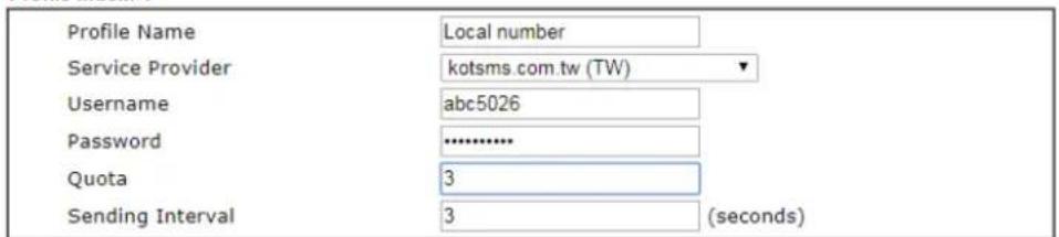
text_image
Profile Name Local number Service Provider kotsms.com.tw (TW) Username abc5026 Password ***** Quota 3 Sending Interval 3 (seconds)Note:
- Only one message can be sent during the "Sending Interval" time.
- If the "Sending Interval" was set to 0, there will be no limitation.

- After finished the settings, click OK to return to previous page. Now you have finished the configuration of the SMS Provider profile setting.
Objects Setting >> SMS Service Object
| Index | Profile Name | SMS Provider |
| 1. | Local number | kotsms.com.tw (TW) |
| 2. | ||
| 3. | ||
| 4. | ||
| 5. | ||
| 6. | ||
| 7. | ||
| 8. | ||
| 9. | Custom 1 | |
| 10. | Custom 2 |
- Open Object Settings>>Notification Object to configure the event conditions of the notification.
Object Settings >> Notification Object
| Index | Profile Name | Settings |
| 1. | ||
| 2. | ||
| 3. | ||
| 4. | ||
| 5. | ||
| 6. | ||
| 7. | ||
| 8. |
- Choose any index number (e.g., Index 1 in this case) to configure conditions for sending the SMS. In the following page, Enter the name of the profile and check the Disconnected and Reconnected boxes for WAN to work in concert with the topic of this paper.
Objects Setting >> Notification Object
Profile Index: 1

text_image
Profile Name WAN_Notify Category Status WAN ✓ Disconnected ✓ Reconnected VPN Tunnel □ Disconnected □ Reconnected WAN Budget □ Limit Reached
- After finished the settings, click OK to return to previous page. You have finished the configuration of the notification object profile setting.
Object Settings >> Notification Object
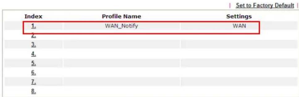
text_image
Set to Factory Default Index Profile Name Settings 1. WAN_Notify WAN 2. 3. 4. 5. 6. 7. 8.- Now, open Applications >> SMS Alert Service. Use the drop down list to choose SMS Provider and the Notify Profile (specify the time of sending SMS). Then, Enter the phone number in the field of Recipient Number (the one who will receive the SMS).
Applications >> SMS Alert Service
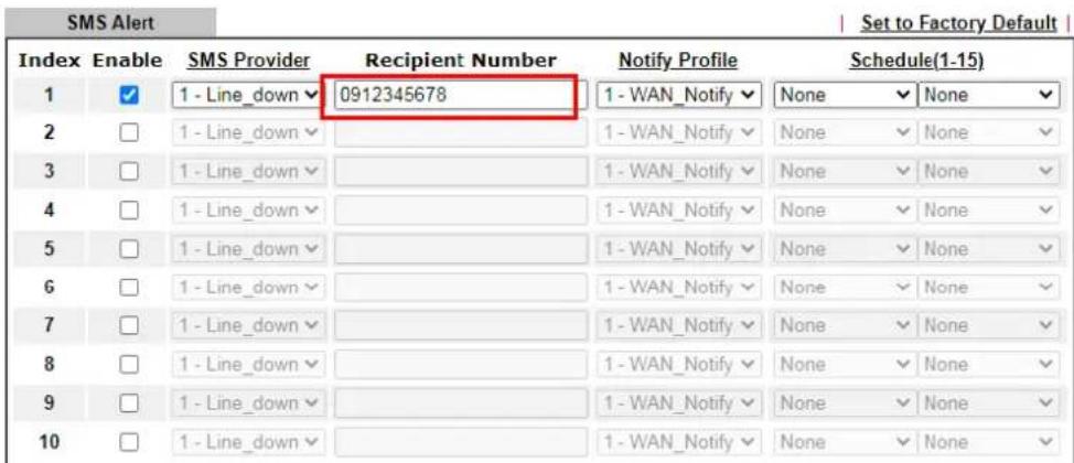
text_image
SMS Alert Set to Factory Default Index Enable SMS Provider Recipient Number Notify Profile Schedule(1-15) 1 ✓ 1 - Line_down ✓ 0912345678 1 - WAN_Notify ✓ None ✓ None ✓ 2 ☐ 1 - Line_down ✓ 1 - WAN_Notify ✓ None ✓ None ✓ 3 ☐ 1 - Line_down ✓ 1 - WAN_Notify ✓ None ✓ None ✓ 4 ☐ 1 - Line_down ✓ 1 - WAN_Notify ✓ None ✓ None ✓ 5 ☐ 1 - Line_down ✓ 1 - WAN_Notify ✓ None ✓ None ✓ 6 ☐ 1 - Line_down ✓ 1 - WAN_Notify ✓ None ✓ None ✓ 7 ☐ 1 - Line_down ✓ 1 - WAN_Notify ✓ None ✓ None ✓ 8 ☐ 1 - Line_down ✓ 1 - WAN_Notify ✓ None ✓ None ✓ 9 ☐ 1 - Line_down ✓ 1 - WAN_Notify ✓ None ✓ None ✓ 10 ☐ 1 - Line_down ✓ 1 - WAN_Notify ✓ None ✓ None ✓Note:
- All the SMS Alert profiles share the same "Sending Interval" setting if they use the same SMS Provider.
- If SMS Provider is "LTE Modem", the "Quota" is controlled by LTE >> SMS Quota Limit and the "Sending Interval" is 3 seconds.
OK Cancel
- Click OK to save the settings. Later, if one of the WAN connections fails in your router, the system will send out SMS to the phone number specified. If the router has only one WAN interface, the system will send out SMS to the phone number while reconnecting the WAN interface successfully.
Remark: How the customize the SMS Provider
Choose one of the Index numbers (9 or 10) allowing you to customize the SMS Provider. In the web page, Enter the URL string of the SMS provider and Enter the username and password. After clicking OK, the new added SMS provider will be added and will be available for you to specify for sending SMS out.
Objects Setting >> SMS / Mail Service Object
Profile Index: 9
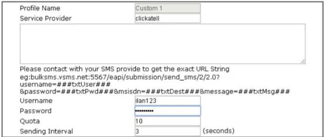
text_image
Profile Name Custom 1 Service Provider clickatell Please contact with your SMS provide to get the exact URL String eg:bulksms.vsms.net:5567/eapi/submission/send_sms/2/2.0? username=### txtUser### &password=### txtPwd### &msisdn=### txtDest### &message=### txtMsg### Username ilan123 Password ****** Quota 10 Sending Interval 3 (seconds)Note:
- Only one message can be sent during the "Sending Interval" time.
- If the "Sending Interval" was set to 0, there will be no limitation.

This page is left blank.
Part VIII Troubleshooting

Troubleshooting
This part will guide you to solve abnormal situations if you cannot access into the Internet after installing the router and finishing the web configuration.
VIII-1 Diagnostics
This section will guide you to solve abnormal situations if you cannot access into the Internet after installing the router and finishing the web configuration. Please follow sections below to check your basic installation status stage by stage.
- Checking if the hardware status is OK or not.
- Checking if the network connection settings on your computer are OK or not.
- Pinging the router from your computer.
- Checking if the ISP settings are OK or not.
- Backing to factory default setting if necessary.
If all above stages are done and the router still cannot run normally, it is the time for you to contact your dealer or DrayTek technical support for advanced help.
Web User Interface
Fisrt, take a look at the menu items under Diagnostics. Diagnostic Tools provide a useful way to view or diagnose the status of your Vigor router.
Diagnostics
Dial-out Triggering
Routing Table
ARP Cache Table
IPv6 Neighbour Table
DHCP Table
NAT Sessions Table
DNS Cache Table
Ping Diagnosis
Data Flow Monitor
Traffic Graph
Trace Route
Syslog Explorer
IPv6 TSPC Status
DoS Flood Table
VII-1-1 Dial-out Triggering
Click Diagnostics and click Dial-out Triggering to open the web page. The internet connection (e.g., PPPoE) is triggered by a package sending from the source IP address.
Diagnostics >> Dial-out Triggering
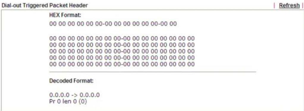
text_image
Dial-out Triggered Packet Header HEX Format: 00 00 00 00 00 00-00 00 00 00 00 00-00 00 00 00 00 00 00 00 00 00-00 00 00 00 00 00 00 00 00 00 00 00 00 00 00 00-00 00 00 00 00 00 00 00 00 00 00 00 00 00 00 00-00 00 00 00 00 00 00 18 00 18 18 18 18 18 18 18 18 18 Decoded Format: 0.0.0.0 -> 1.2.3.3.3. Pr 1 len 1 (1)Available settings are explained as follows:
| Item | Description |
| Decoded Format It shows the source IP address (local), destination IP (remote) address, the protocol and length of the package. | |
| Refresh Click it to reload the page. | |
VIII-1-2 Routing Table
Click Diagnostics and click Routing Table to open the web page.
Diagnostics >> View Routing Table
IPv4
| Key | Destination | Gateway | Interface |
| C~ | 192.168.1.0/ 255.255.255.0 | directly connected | LAN1 |
Key
C: Connected S: Static R: RIP *: default \~: private
Note:
WAN5, WAN6, WAN7 are router-borne WANs.
IPv6
| Destination | Interface Flags | Metric | Next Hop | |
| FE80::/64 | LAN1 | U | 256 | :: |
| FE80::/64 | LAN2 | U | 256 | :: |
| FE80::/64 | DMZ | U | 256 | :: |
| FF00::/8 | LAN1 | U | 256 | :: |
| FF00::/8 | LAN2 | U | 256 | :: |
| FF00::/8 | DMZ | U | 256 | :: |

Show Detail
Available settings are explained as follows:
| Item | Description |
| Refresh Click it to reload the page. | |
VIII-1-3 ARP Cache Table
Click Diagnostics and click ARP Cache Table to view the content of the ARP (Address Resolution Protocol) cache held in the router. The table shows a mapping between an Ethernet hardware address (MAC Address) and an IP address.
Diagnostics >> View ARP Cache Table
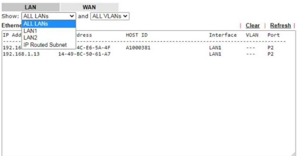
text_image
LAN Show: ALL LANs and ALL VLANs Etherne ALL LANs LAN1 LAN2 IP Routed Subnet dress HOST ID Interface VLAN Port 192.16 4C-E6-5A-4F A1000381 LAN1 --- P2 192.168.1.13 14-49-BC-50-61-A7 LAN1 --- P2□ Show Comment
Available settings are explained as follows:
| Item | Description |
| Show Specify LAN and VLAN | to display related information.In default, this page will display all of the information about LAN and VLAN. |
| Refresh Click it to reload the page. | |
VIII-1-4 IPv6 Neighbour Table
The table shows a mapping between an Ethernet hardware address (MAC Address) and an IPv6 address. This information is helpful in diagnosing network problems, such as IP address conflicts, etc.
Click Diagnostics and click IPv6 Neighbour Table to open the web page.
Diagnostics >> View IPv6 Neighbour Table
| IPv6 Neighbour Table | | Refresh | | ||
| IPv6 Address | Mac Address | Interface | State |
| FF02::1:3 | 33-33-00-01-00-03 | LAN1 | CONNECTED |
Available settings are explained as follows:
| Item | Description |
| Refresh Click it to reload the page. | |
VIII-1-5 DHCP Table
The facility provides information on IP address assignments. This information is helpful in diagnosing network problems, such as IP address conflicts, etc.
Click Diagnostics and click DHCP Table to open the web page.
Diagnostics >> View DHCP Assigned IP Addresses
IPv4 Address Assignment Table
Show : ALL LANs
| DHCP IP Assignment Table | Other IP Assignment Table | □ Show Comment | Refresh | | ||
| Index | IP Address | MAC Address | Leased Time | HOST ID |
| [LAN1 | : DHCP Server On | IP Pool: 192.168.1.10 ~ 192.168.1.209] | ||
IPv6 Address Assignment Table
| Index | IPv6 Address | IAID | Link-layer Address | Leased Time |
Available settings are explained as follows:
| Item | Description |
| Index It displays the connection item number. | |
| IP Address It displays the IP address assigned by this router for specified PC. | |
| MAC Address | It displays the MAC address for the specified PC that DHCP assigned IP address for it. |
| Leased Time It displays the leased time of the specified PC. | |
| HOST ID | It displays the host ID name of the specified PC. |
| Refresh Click it to reload the page. | |
VIII-1-6 NAT Sessions Table
Click Diagnostics and click NAT Sessions Table to open the list page.
Diagnostics >> NAT Sessions Table
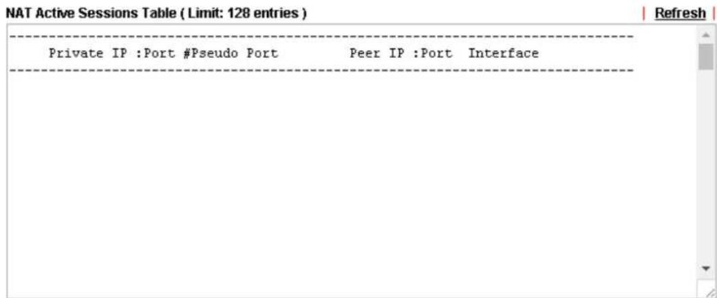
text_image
NAT Active Sessions Table ( Limit: 128 entries ) Private IP :Port #Pseudo Port Peer IP :Port Interface RefreshAvailable settings are explained as follows:
| Item | Description |
| Private IP:Port It indicates the source IP address and port of local PC. | |
| #Pseudo Port It indicates the temporary port of the router used for NAT. | |
| Peer IP:Port It indicates the destination IP address and port of remote host. | |
| Interface It displays the representing number for different interface. | |
| Refresh Click it to reload the page. | |
VIII-1-7 DNS Cache Table
Click Diagnostics and click DNS Cache Table to open the web page.
The record of domain Name and the mapping IP address for answering the DNS query from LAN will be stored on Vigor router's Cache temporarily and displayed on Diagnostics >> DNS Cache Table.
Diagnostics >> DNS Cache Table
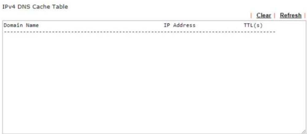
text_image
IPv4 DNS Cache Table | Clear | Refresh | Domain Name IP Address TTL(s)| IPv6 DNS Cache Table | ||
| Clear Refresh | ||
| Domain Name | IP Address | TTL(s) |
| - - - - - - - - - - - - - - - - - - - - - - - - - - - - - - - - - - - - - - - - - - - - - - - - - - - - - - - - - - - - - - - - - - - - - - - - - - - - - - - - - - - - - - - - - - - - - - - - - - - - - | ||
☐ When an entry's TTL is larger than 0 s, this entry will be deleted from the table.
OK
Available settings are explained as follows:
| Item | Description |
| Clear Click this link to remove the result on the window. | |
| Refresh Click it to reload the page. | |
| When an entry's TTL is larger than.... | Check the box the Enter the value of TTL (time to live) for each entry. Click OK to enable such function.It means when the TTL value of each DNS query reaches the threshold of the value specified here, the corresponding record will be deleted from router's Cache automatically. |
VIII-1-8 Ping Diagnosis
Click Diagnostics and click Ping Diagnosis to open the web page.
Diagnostics >> Ping Diagnosis
Ping Diagnosis
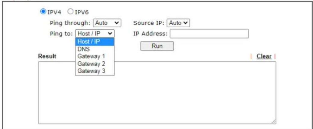
text_image
IPV4 IPV6 Ping through: Auto Source IP: Auto Ping to: Host / IP Host / IP DNS Gateway 1 Gateway 2 Gateway 3 Source IP: Auto IP Address: Run Result ClearNote:
- If you want to ping a LAN PC or you don't want to specify which WAN to ping through, please select "Auto" in Ping Through.
- If you select "Auto" in Source IP, we will fill Source IP according to the interface you ping through.
or
Diagnostics >> Ping Diagnosis
Ping Diagnosis
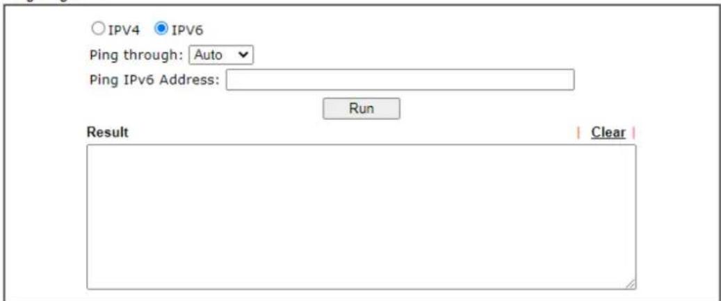
text_image
IPV4 IPV6 Ping through: Auto Ping IPv6 Address: Run Result ClearNote:
- If you want to ping a LAN PC or you don't want to specify which WAN to ping through, please select "Auto" in Ping Through.
- If you select "Auto" in Source IP, we will fill Source IP according to the interface you ping through.
Available settings are explained as follows:
| Item | Description |
| IPV4 /IPV6 Choose the interface for such function. | |
| Ping through Use the drop down list to choose the WAN interface that you want to ping through or chooseAuto to be determined by the router automatically. | |
| Ping to Use the drop down list to choose the destination that you want to ping. | |
| IP Address | Enter the IP address of the Host/IP that you want to ping. |
| Ping IPv6 Address Enter the IPv6 address that you want to ping. | |
| Run | Click this button to start the ping work. The result will be displayed on the screen. |
| Clear Click this link to remove the result on the window. | |
VIII-1-9 Data Flow Monitor
This page displays the running procedure for the IP address monitored and refreshes the data in an interval of several seconds. The IP address listed here is configured in Bandwidth Management. You have to enable IP bandwidth limit and IP session limit before invoking Data Flow Monitor. If not, a notification dialog box will appear to remind you enabling it.
Bandwidth Management >> Sessions Limit
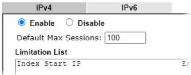
text_image
IPv4 IPv6 Enable ○ Disable Default Max Sessions: 100 Limitation List Index Start IP EnClick Diagnostics and click Data Flow Monitor to open the web page. You can click IP Address, TX rate, RX rate or Session link for arranging the data display.
Diagnostics >> Data Flow Monitor
| Index | IP Address | TX rate(Kbps) | RX rate(Kbps) | Sessions | Action |
| Current / Peak / Speed | Current / Peak / Speed | Current / Peak | |||
| WAN2 | --- | 0 / 0 / Auto | 0 / 0 / Auto | 0 | |
| LTE | --- | 0 / 0 / Auto | 0 / 0 / Auto | 0 | |
| Total | 0 / 0 / Auto | 0 / 0 / Auto | 0 / 0 |
Note:
-
Click "Block" to prevent specified PC from surfing Internet for 5 minutes.
-
The IP blocked by the router will be shown in red, and the session column will display the remaining time that the specified IP will be blocked.
3.(Kbps): shared bandwidth
+ : residual bandwidth used
Current/Peak are average.
Available settings are explained as follows:
| Item | Description |
| Enable Data Flow Monitor | Check this box to enable this function. |
| Refresh Seconds Use the drop down list to choose the time interval of refreshing data flow that will be done by the system automatically. | |
| Refresh Click this link to refresh this page manually. | |
| Index Display the number of the data flow. | |
| IP Address Display the IP address of the monitored device. | |
| TX rate (kbps) | Display the transmission speed of the monitored device. |
| RX rate (kbps) Display the receiving speed of the monitored device. | |
| Sessions Display the session number that you specified in Limit Session web page. | |
| Action | Block - can prevent specified PC accessing into Internet within 5 minutes.Unblock -The device with the IP address will be blocked for five minutes. The remaining time will be shown on the session column. Click it to cancel the IP address blocking. |
| Current /Peak/Speed Current means current transmission rate and receiving rate for WAN interface.Peak means the highest peak value detected by the router in data transmission.Speed means line speed specified in WAN>>General Setup. If you do not specify any rate at that page, here will display Auto for instead. | |
VIII-1-10 Traffic Graph
Click Diagnostics and click Traffic Graph to open the web page. Choose WAN2/LTE Bandwidth, Sessions, Ping Detect, daily or weekly for viewing different traffic graph. Click Reset to zero the accumulated RX/TX (received and transmitted) data of WAN. Click Refresh to renew the graph at any time.
Diagnostics >> Traffic Graph

line
| Bandwidth | Session Type | | --------- | ------------ | | 0 | RX (Kbps) | | 0 | TX (Kbps) |The horizontal axis represents time. Yet the vertical axis has different meanings. For WAN2/ LTE Bandwidth chart, the numbers displayed on vertical axis represent the numbers of the transmitted and received packets in the past.
For Sessions chart, the numbers displayed on vertical axis represent the numbers of the NAT sessions during the past.
VIII-1-11 Trace Route
Click Diagnostics and click Trace Route to open the web page. This page allows you to trace the routes from router to the host. Simply Enter the IP address of the host in the box and click Run. The result of route trace will be shown on the screen.
Diagnostics >> Trace Route
Trace Route
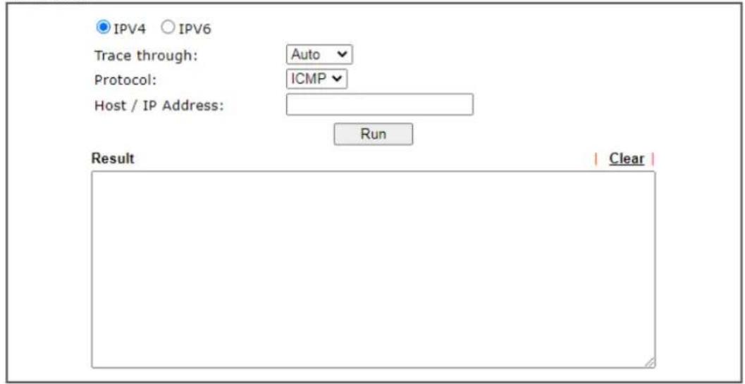
text_image
IPV4 IPV6 Trace through: Auto Protocol: ICMP Host / IP Address: Run Result Clearor
Diagnostics >> Trace Route
Trace Route
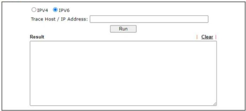
text_image
○ IPv4 ○ IPv6 Trace Host / IP Address: Run Result | Clear |Available settings are explained as follows:
| Item | Description |
| IPv4 / IPv6 Click one of them to display corresponding information for it. | |
| Trace through | Use the drop down list to choose the interface that you want to ping through. |
| Protocol Use the drop down | list to choose the protocol that you want to ping through. |
| Host/IP Address It indicates | the IP address of the host. |
| Trace Host/IP Address It indicates the IPv6 address of the host. | |
| Run Click this button to start route tracing work. | |
| Clear Click this link to remove the result on the window. | |
VIII-1-12 Syslog Explorer
Such page provides real-time syslog and displays the information on the screen.
For Web Syslog
This page displays the time and message for User/ Firewall/ call/ WAN/ VPN settings. You can check Enable Web Syslog, specify the type of Syslog and choose the display mode you want. Later, the event of Syslog with specified type will be shown for your reference.
Diagnostics >> Syslog Explorer

text_image
Web Syslog Enable Web Syslog Syslog Type All ▼ Display Mode Export | Refresh | Clear | Stop record when fulls Time MessageAvailable settings are explained as follows:
| Item | Description |
| Enable Web Syslog Check this box to enable the function of Web Syslog. | |
| Syslog Type Use the drop down list to specify a type of Syslog to be displayed. | 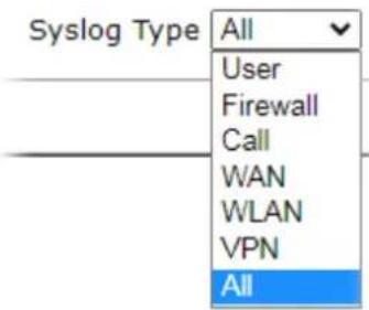 |
| Export Click this link to save the data as a file. | |
| Refresh Click this link to refresh this page manually. | |
| Clear Click this link to clear information on this page. | |
| Display Mode There are two modes for you to choose. | |
| Stop record when fullsStop record when fullsAlways record the new event | |
| Stop record when fulls - When the capacity of syslog is full, the system will stop recording.Always record the new event - only the newest events will be recorded by the system. | |
| Time Display the time of the event occurred. | |
| Message Display the information for each event. | |
VIII-1-13 IPv6 TSPC Status
IPv6 TSPC status web page could help you to diagnose the connection status of TSPC.
If TSPC has configured properly, the router will display the following page when the user connects to tunnel broker successfully.
Diagnostics >> IPv6 TSPC Status
| WAN1 | WAN2 | LTE | | Refresh | |
| TSPC Disabled | |||
Available settings are explained as follows:
| Item | Description |
| Refresh Click this link to refresh this page manually. | |
VIII-1-14 DoS Flood Table
This page can display content of IP connection detected by DoS Flooding Defense mechanism. It is useful and convenient for network engineers (e.g., MIS engineer) to inspect the network environment to find out if there is any abnormal connection.
Information of IP traced and destination port used for SYN Flood, UDP Flood and ICMP Flood attacks will be detected and shown respectively on different pages.
Moreover, IP address detected and suspected to attack the network system can be blocked shortly by clicking the Block button shown on pages of SYN Flood, UDP Flood and ICMP Flood.
Diagnostics >> DoS Flood Table
IPv4
| SYN Flood | UDP Flood | ICMP Flood | | Refresh | |
| Tracing IP Destination Port | |||
| 192.168.1.22 | 80 | Block | |
| 192.168.1.205 | 40005(○) | Block | |
IPv6

text_image
SYN Flood UDP Flood ICMP Flood | Refresh | Tracing IP Destination Port --------
Info
The icon - (✗) - means there is something wrong (e.g., attacking the system) with that IP address.
VIII-2 Checking If the Hardware Status Is OK or Not
Follow the steps below to verify the hardware status.
- Check the power line and WLAN/LAN cable connections.
Refer to "I-2 Hardware Installation" for details.
- Turn on the router. Make sure the Activity LED blink once per second and the correspondent LAN LED is bright.

text_image
VigorLTE 200n- If not, it means that there is something wrong with the hardware status. Simply back to "I-2 Hardware Installation" to execute the hardware installation again. And then, try again.
VIII-3 Checking If the Network Connection Settings on Your
Computer Is OK or Not
Sometimes the link failure occurs due to the wrong network connection settings. After trying the above section, if the link is stilled failed, please do the steps listed below to make sure the network connection settings is OK.
For Windows

Info
The example is based on Windows 7. As to the examples for other operation systems, please refer to the similar steps or find support notes in www.DrayTek.com.
- Open All Programs>>Getting Started>>Control Panel. Click Network and Sharing Center.





- In the following window, click Change adapter settings.
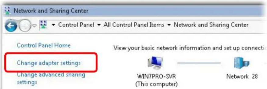
text_image
Network and Sharing Center Control Panel Home Change adapter settings Change advanced sharing settings View your basic network information and set up connection WIN7PRO-SVR (This computer) Network 28- Icons of network connection will be shown on the window. Right-click on Local Area Connection and click on Properties.
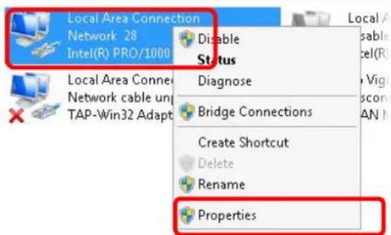
text_image
Local Area Connection Network 28 Intel(R) PRO/1000 Disable Status Diagnose Bridge Connections Create Shortcut Delete Rename Properties- Select Internet Protocol Version 4 (TCP/IP) and then click Properties.
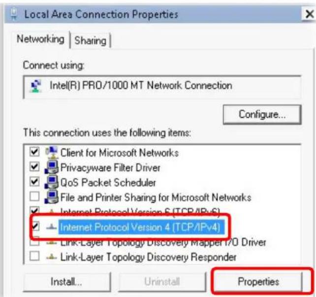
text_image
Local Area Connection Properties Networking | Sharing | Connect using: Intel(R) PRO/1000 MT Network Connection Configure... This connection uses the following items: Client for Microsoft Networks Privacyware Filter Driver QoS Packet Scheduler File and Printer Sharing for Microsoft Networks Internet Protocol Version 6 (TCP/IPv6) Internet Protocol Version 4 (TCP/IPv4) Link-Layer Topology Discovery Mapper I/O Driver Link-Layer Topology Discovery Responder Install... Uninstall Properties- Select Obtain an IP address automatically and Obtain DNS server address automatically. Finally, click OK.
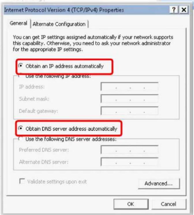
text_image
Internet Protocol Version 4 (TCP/IPv4) Properties General | Alternate Configuration | You can get IP settings assigned automatically if your network supports this capability. Otherwise, you need to ask your network administrator for the appropriate IP settings. Obtain an IP address automatically Use the following IP address: IP address: .... Subnet mask: .... Default gateway: .... Obtain DNS server address automatically Use the following DNS server addresses: Preferred DNS server: .... Alternate DNS server: .... Validate settings upon exit Advanced... OK CancelFor Mac OS
- Double click on the current used Mac OS on the desktop.
- Open the Application folder and get into Network.
- On the Network screen, select Using DHCP from the drop down list of Configure IPv4.
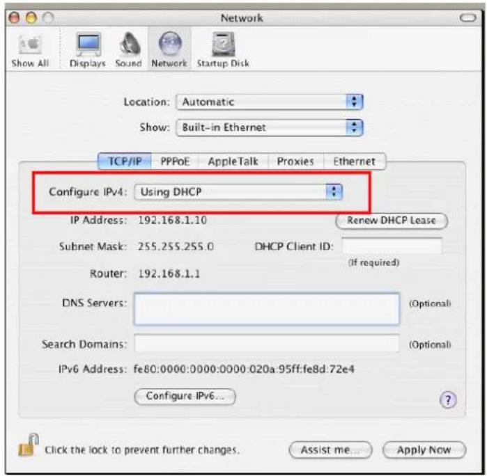
text_image
Network Show All Displays Sound Network Startup Disk Location: Automatic Show: Built-in Ethernet TCP/IP PPPoE AppleTalk Proxies Ethernet Configure IPv4: Using DHCP IP Address: 192.168.1.10 Renew DHCP Lease Subnet Mask: 255.255.255.0 DHCP Client ID: Router: 192.168.1.1 (If required) DNS Servers: Search Domains: IPv6 Address: fe80:0000:0000:0000:020a:95ff:fe8d:72e4 Configure IPv6... Click the lock to prevent further changes. Assist me... Apply NowVIII-4 Pinging the Router from Your Computer
The default gateway IP address of the router is 192.168.1.1. For some reason, you might need to use "ping" command to check the link status of the router. The most important thing is that the computer will receive a reply from 192.168.1.1. If not, please check the IP address of your computer. We suggest you setting the network connection as get IP automatically.
Please follow the steps below to ping the router correctly.
For Windows
- Open the Command Prompt window (from Start menu> Run).
- Type command (for Windows 95/98/ME) or cmd. The DOS command dialog will appear.
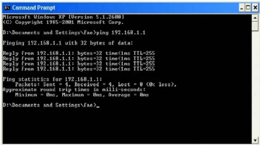
text_image
Microsoft Windows XP [Version 5.1.2600] (C) Copyright 1985-2001 Microsoft Corp. D:\Documents and Settings\fae>ping 192.168.1.1 Pinging 192.168.1.1 with 32 bytes of data: Reply from 192.168.1.1: bytes=32 time<1ms TTL=255 Reply from 192.168.1.1: bytes=32 time<1ms TTL=255 Reply from 192.168.1.1: bytes=32 time<1ms TTL=255 Reply from 192.168.1.1: bytes=32 time<1ms TTL=255 Ping statistics for 192.168.1.1: Packets: Sent = 4, Received = 4, Lost = 0 (0% loss), Approximate round trip times in milli-seconds: Minimum = 0ms, Maximum = 0ms, Average = 0ms D:\Documents and Settings\fae>-
Type ping 192.168.1.1 and press [Enter]. If the link is OK, the line of "Reply from 192.168.1.1:bytes=32 time<1ms TTL=255" will appear.
-
If the line does not appear, please check the IP address setting of your computer.
For Mac OS (Terminal)
- Double click on the current used MacOs on the desktop.
- Open the Application folder and get into Utilities.
- Double click Terminal. The Terminal window will appear.
- Type ping 192.168.1.1 and press [Enter]. If the link is OK, the line of "64 bytes from 192.168.1.1: icmp_seq=0 ttl=255 time=xxxx ms" will appear.
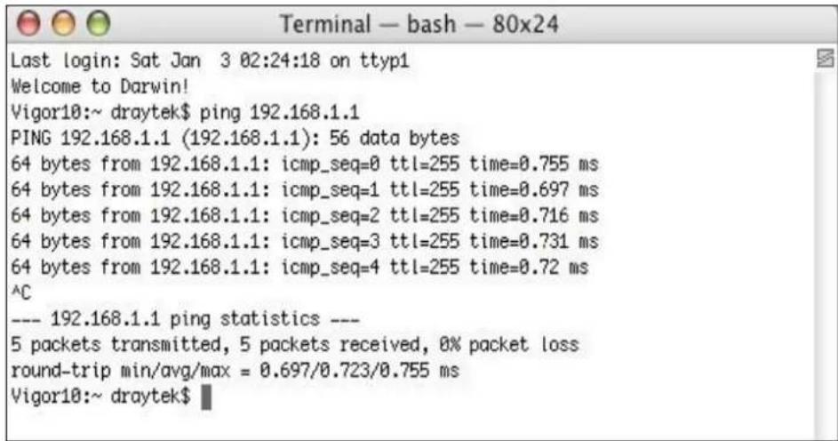
text_image
Terminal — bash — 80x24 Last login: Sat Jan 3 02:24:18 on ttyp1 Welcome to Darwin! Vigor10:~ draytek$ ping 192.168.1.1 PING 192.168.1.1 (192.168.1.1): 56 data bytes 64 bytes from 192.168.1.1: icmp_seq=0 ttl=255 time=0.755 ms 64 bytes from 192.168.1.1: icmp_seq=1 ttl=255 time=0.697 ms 64 bytes from 192.168.1.1: icmp_seq=2 ttl=255 time=0.716 ms 64 bytes from 192.168.1.1: icmp_seq=3 ttl=255 time=0.731 ms 64 bytes from 192.168.1.1: icmp_seq=4 ttl=255 time=0.72 ms ^C --- 192.168.1.1 ping statistics --- 5 packets transmitted, 5 packets received, 0% packet loss round-trip min/avg/max = 0.697/0.723/0.755 ms Vigor10:~ draytek$VIII-5 Checking If the ISP Settings are OK or Not
If WAN connection cannot be up, check if the LEDs (according to the LED explanations listed on section 1-2) are correct or not. If the LEDs are off, please:
- Change the Physical Type from Auto negotiation to other values (e.g., 100M full duplex).
● Next, check if the LEDs on Vigor router are on or not. - If not, please install an additional switch for connecting both Vigor router and the modem offered by ISP. Then, check if the LEDs on Vigor router are on or not.
- If the problem of LEDs cannot be solved by the above measures, please contact with the nearest reseller, or send an e-mail to DrayTek FAE for technical support.
- Check if the settings offered by ISP are configured well or not.
When the LEDs are on and correct, yet the WAN connection still cannot be up, please:
- Open WAN >> Internet Access page and then check whether the ISP settings are set correctly. Click Details Page of WAN1 to review the settings that you configured previously.
VIII-6 Backing to Factory Default Setting If Necessary
Sometimes, a wrong connection can be improved by returning to the default settings. Try to reset the router by software or hardware. Such function is available in Admin Mode only.

Info
After pressing factory default setting, you will loose all settings you did before. Make sure you have recorded all useful settings before you pressing. The password of factory default is null.
Software Reset
You can reset the router to factory default via Web page. Such function is available in Admin Mode only.
Go to System Maintenance and choose Reboot System on the web page. The following screen will appear. Choose Using factory default configuration and click Reboot Now. After few seconds, the router will return all the settings to the factory settings.
System Maintenance >> Reboot System
Reboot System
Do you want to reboot your router?

Using current configuration

Using factory default configuration
Reboot Now
Auto Reboot Time Schedule
Schedule Profile
None

None

3
None
Note:
Action and Duration Time settings will be ignored.
OK
Cancel
Hardware Reset
While the router is running (ACT LED blinking), press the Factory Reset button and hold for more than 5 seconds. When you see the ACT LED blinks rapidly, please release the button. Then, the router will restart with the default configuration.
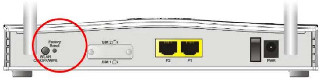
text_image
Factory Reset WLAN C/OFF/WPS SIM 2 □ SIM 1 □ P2 P1 PWRAfter restore the factory default setting, you can configure the settings for the router again to fit your personal request.
VIII-7 Contacting DrayTek
If the router still cannot work correctly after trying many efforts, please contact your dealer for further help right away. For any questions, please feel free to send e-mail to support@DrayTek.com.
Part IX Telnet Commands
Accessing Telnet of VigorLTE 200
This chapter also gives you a general description for accessing telnet and describes the firmware versions for the routers explained in this manual.

Info
For Windows 7 user, please make sure the Windows Features of Telnet Client has been turned on under Control Panel>>Programs.
Type cmd and press Enter. The Telnet terminal will be open later.

text_image
Programs (1) cmd See more results cmdIn the following window, type Telnet 192.168.1.1 as below and press Enter. Note that the IP address in the example is the default address of the router. If you have changed the default, enter the current IP address of the router.
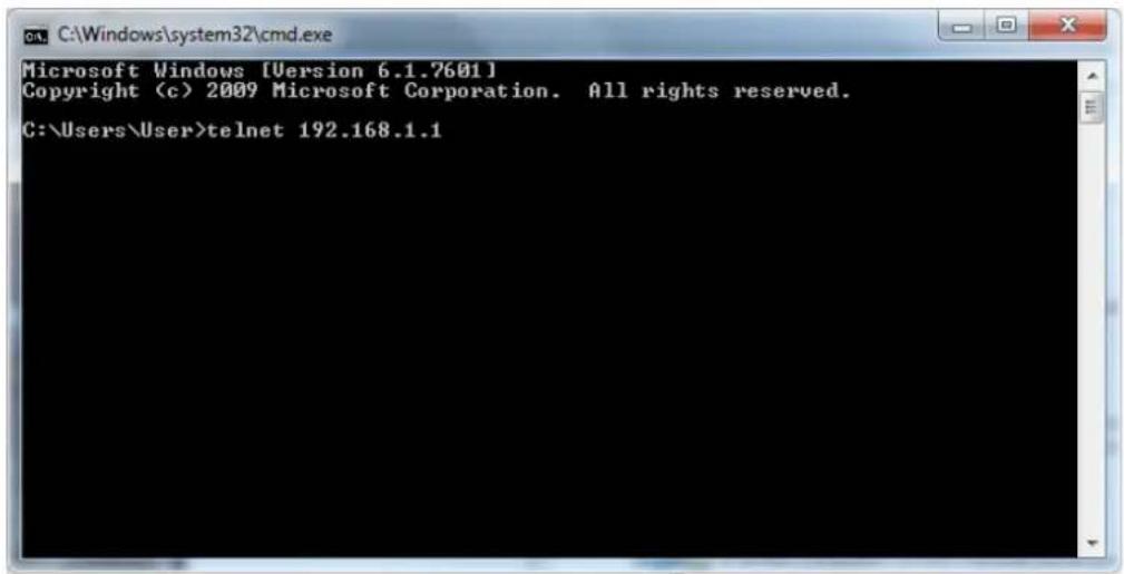
text_image
Microsoft Windows [Version 6.1.7601] Copyright (c) 2009 Microsoft Corporation. All rights reserved. C:\Users\User>telnet 192.168.1.1Next, type admin/ admin for Account/ Password. Then, type ?. You will see a list of valid/ common commands depending on the router that your use.
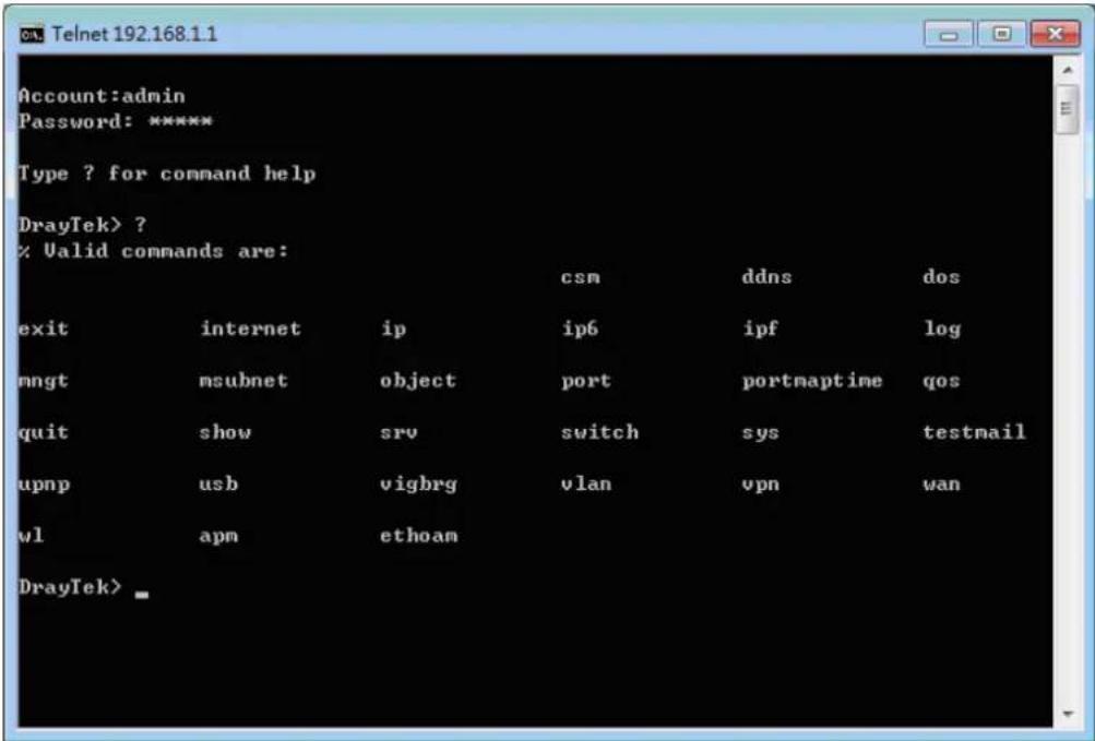
text_image
Account:admin Password: ***** Type ? for command help DrayTek> ? % Valid commands are: csm ddns dos exit internet ip ip6 ipf log mngt msubnet object port portmaptime qos quit show srv switch sys testmail upnp usb vigbrg vlan vpn wan wl apm ethoam DrayTek>Telnet Command: csm appe prof
Commands under CSM allow you to set CSM profile to define policy profiles for different policy of IM (Instant Messenger)/ P2P (Peer to Peer) application.
“ csm appe prof “ is used to configure the APP Enforcement Profile name. Such profile will be applied in Default Rule of Firewall>>General Setup for filtering.
Syntax
csm appe prof -i
csm appe prof -i
csm appe prof -i
Syntax Description
| Parameter | Description |
| It means to specify the index number of CSM profile. INDEX= 1~32. | |
| - v It means to view the configuration of the CSM profile. | |
| - nIt means to set | a name for the CSM profile.: Specify a name for the CSM profile, less then 15 characters. |
| setdefault Reset to default | settings. |
Example
> csm appe prof -i 1 -n game
The name of APPE Profile 1 was setted.
> csm appe prof -i 1 setdefault
APPE Profile 1 was reseted.
Telnet Command:csm appe set
It is used to configure group settings for IM/ P2P/ Protocol and Others in APP Enforcement Profile.
csm appe set -i INDEX -v
csm appe set -i INDEX -e
csm appe set -i INDEX -d
Syntax Description
| Parameter | Description |
| It means to specify the index number of CSM profile. INDEX= 1~32. | |
| - vView the IM/ P | P2P/ Protocol or Others configuration of the CSM profile.= IM, P2P, Protocol,or Others. |
| -e Enable to block specific | application. |
| -d Disable to block specific | application. |
<AP_IDX> Specify the index number of the application here.
AP_IDX=1~119
Example
> csm appe set -i 1 -e 1
Profile 1 - : AIM is enabled.
> csm appe set -i 32 -e 90
Profile 32 - : PPTV is enabled.
Telnet Command: csm appe show
It is used to display group (IM/ P2P/ Protocol and Others) information APP Enforcement Profile. csm appe show <-a/-i/-p/-t/-m>
Syntax Description
| Parameter | Description |
| -a View the configuration status for All groups. | |
| -i View the configuration status of IM group. | |
| -p View the configuration status of P2P group. | |
| -t View the configuration status of protocol group. | |
| -m View the configuration status of Others group. | |
Example
| > csm appe show -t | ||||
| Type | Index | Name | Version | Advance |
| Advanced Option: (M) essayage, (F) ile Transfer, (G) ame, (C) onference, and (O)ther Activities | ||||
| PROTOCOL | 52 | DB2 | ||
| PROTOCOL | 53 | DNS | ||
| PROTOCOL | 54 | FTP | ||
| PROTOCOL | 55 | HTTP | 1.1 | |
| PROTOCOL | 56 | IMAP | 4.1 | |
| PROTOCOL | 57 | IMAP STARTTLS | 4.1 | |
| PROTOCOL | 58 | IRC | 2.4.0 | ...... |
Telnet Command: csm appe config
It is used to display the configuration status (enabled or disabled) for IM/ P2P/ Protocol/ Other applications.
csm appe config -v
Syntax Description
| Parameter | Description |
| It means to specify the index number of CSM profile. INDEX= 1~32. | |
| -i View the configuration status of IM group. | |
| -p View the configuration status of P2P group. | |
| -t View the configuration status of protocol group. | |
| -m View the configuration status of Others group. | |
Example
| > csm appe config -v 1 -m | |||||
| Group | Type | Index | Name | Enable | A |
| vance Enable | |||||
| Advance abbreviation: Message, File Transfer, Game, Conference, and Other Advance abbreviation: : M, F, G, C, and O | |||||
| OTHERS | TUNNEL | 75 | DNSCrypt | Disable | |
| OTHERS | TUNNEL | 76 | DynaPass | Disable | |
| OTHERS | TUNNEL | 77 | FreeU | Disable | |
| OTHERS | TUNNEL | 78 | HTTP Proxy | Disable | |
| OTHERS | TUNNEL | 79 | HTTP Tunnel | Disable | |
| OTHERS | TUNNEL | 80 | Hamachi | Disable | |
| OTHERS | TUNNEL | 81 | Hotspot Shield | Disable | |
| OTHERS | TUNNEL | 82 | MS Teredo | Disable | |
| OTHERS | TUNNEL | 83 | PGPNet | Disable | |
| OTHERS | TUNNEL | 84 | Ping Tunnel | Disable | |
| . | |||||
| . | |||||
| . | |||||
| Total 66 APPs | |||||
| > | |||||
Telnet Command: csm ucf
It is used to configure settings for URL control filter profile.
Syntax
csm ucf show
csm ucf setdefault
csm ucf msg MSG
csm ucf obj csm ucf obj csm ucf obj csm ucf obj csm ucf obj csm ucf obj Syntax Description It means to configure the settings regarding to URL Access Control (uac). It means to configure the settings regarding to Web Feature (wf). Syntax Description It means to configure the settings regarding to web control filter (wcf). csm wcf show csm wcf look csm wcf cache csm wcf server WCF_SERVER csm wcf msg MSG csm wcf setdefault csm wcf obj csm wcf obj csm wcf obj csm wcf obj csm wcf obj csm wcf obj csm wcf obj csm wcf obj csm wcf obj Syntax Description Example Displays the DDNS log. Example Enables or disables the DDNS function. ddns enable <0/1> Syntax Description Example This command allows users to set Dynamica DNS account. ddns set option Syntax Description Sets and displays the DDNS time. ddns time This command will update DDNS automatically. This command will return DDS with factory default settings. This command allows users to check the content of selected DDNS account. ddns show -i This command allows users to configure the settings for DoS defense system. Syntax Description Type this command will leave telnet window. This command allows you to configure detailed settings for WAN connection. internet - Syntax Description This command allows users to enable or disable the public subnet for your router. ip pubsubnet This command allows to set the IP routed subnet for the router. ip pubaddr ? ip pubaddr This command allows users to set the mask for IP routed subnet of your router. ip pubmask? ip pubmask Syntax Description This command is used for configuring WAN IP Alias. ip aux add ip aux remove Syntax Description This command allows users to set/ add a specified LAN IP your router. ip addr Syntax Description When the LAN IP address is changed, the start IP address of DHCP server are still the same. To make the IP assignment of the DHCP server being consistent with this new IP address (they should be in the same network segment), the IP address of the PC must be fixed with the same LAN IP address (network segment) set by this command for accessing into the web user interface of the router. Later, modify the start addresses for the DHCP server. This command allows users to set/ add a specified netmask for your router. ip nmask Syntax Description ARP displays the matching condition for IP and MAC address. ip arp accept <0/1/2/3/4/5/status> ip arp setCacheLife In which, arp add allows users to add a new IP address into the ARP table; arp del allows users to remove an IP address; arp flush allows users to clear arp cache; arp status allows users to review current status for the arp table; arp accept allows to accept or reject the source / destination MAC address; arp setCacheLife allows users to configure the duration in which ARP caches can be stored on the system. If ip arp setCacheLife is set with "60", it means you have an ARP cache at 0 second. Sixty seconds later without any ARP messages received, the system will think such ARP cache is expired. The system will issue a few ARP request to see if this cache is still valid. Syntax Description This command is available for WAN DHCP. ip dhcpc option ip dhcp option -l ip dhcp option -d ip dhcpc option -e <1 or 0> -w ip dhcpc option -e <1 or 0> -w ip dhcpc option -e <1 or 0> -w ip dhcpc option -u ip dhcpc release ip dhcpc renew ip dhcp status Syntax Description This command allows users to ping IP address of WAN1/ WAN2/ PVC3/ PVC4/ PVC5 for verifying if the WAN connection is OK or not. ip ping Syntax Description This command allows users to trace the routes from the router to the host. ip tracert Syntax Description Example This command allows users to access specified device by telnet. ip telnet Syntax Description Example This command allows users to set the RIP (routing information protocol) of IP. ip rip <0/1/2> Syntax Description This command allows users to set the RIP (routing information protocol) of WAN IP. ip wanrip Syntax Description This command allows users to set static route. Syntax Description This command allows users to enable/ disable igmp proxy server. ip igmp_proxy set ip igmp_proxy reset ip igmp_proxy wan <1\~4> ip igmp_proxy query ip igmp_proxy ppp <0/1> ip igmp_proxy status ip igmp_proxy version Syntax Description This command allows users to enable or disable IGMP snoop function. ip igmp_snoop enable ip igmp_snoop disable ip igmp_snoop status ip igmp_snoop txquery ip igmp_snoop chkleave ip igmp_snoop separate Syntax Description This command allows users to enable or disable IGMP Fast Leave function. Syntax Description Specify MAC address of certain device as the DMZ host. Syntax Description This command allows users to set DMZ mode. ip dmzswitch active_trueip Syntax Description Example This command allows users to set maximum session limit number for the specified IP; set message for exceeding session limit and set how many seconds the IP session block works. ip session on ip session off ip session default ip session defaultp2p ip session status ip session show ip session timer ip session ip session Syntax Description This command allows users to set maximum bandwidth limit number for the specified IP. This command allows users to set IP-MAC binding for LAN host. ip bindmac on ip bindmac off ip bindmac ip bindmac add ip bindmac del ip bindmac subnet ip bindmac show Syntax Description This command is used to set the maximum number of NAT users. ip maxnatuser Syntax Description This command is used to enable/ disable the IP Spoofing Defense. ip spoofdef Syntax Description This command allows users to set the IPv6 address for your router. ip6 addr -s ip6 addr -d ip6 addr -a ip6 addr -v ip6 addr -t ip6 addr -o <1/2> ip6 addr -o 3 ip6 addr -l ip6 addr <-p/-b> ip6 addr -x ip6 addr -c ip6 addr -e Syntax Description This command is used to configure option-request settings for DHCPv6 client. ip6 dhcp req_opt This command allows you to use DHCPv6 protocol to obtain IPv6 address from server. ip6 dhcp client This command allows you to configure DHCPv6 server. ip6 dhcp server -< Syntax Description This command allows you to configure settings for accessing Internet. ip6 internet <- This command allows you to set a IPv6 neighbour table. Syntax Description Example This command allows you to add a proxy neighbour. Syntax Description This command allows you to set route for IPv6 connection. Syntax Description Example This command allows you to pin an IPv6 address or a host. ip6 ping Syntax Description Example This command allows you to trace the routes from the router to the host. ip6 tracert Syntax Description Example This command allows you to display TSPC status. ip6 tspc Syntax Description This command allows you to enable or disable RADVD server. Ip6 radvd Syntax Description This command allows you to manage the settings for access list. ip6 mngt /ist ip6 mngt list add ip6 mngt list remove ip6 mngt list flush ip6 mngt status ip6 mngt Syntax Description This command allows you to check the online status of IPv6 WAN/USB. ip6 online This command allows you to set IPv6 settings for WAN interface with connection type of AICCU. ip6 aiccu -i ip6 aiccu -i This command allows you to set IPv6 settings for NTP (Network Time Protocols) server. ip6 ntp -h ip6 ntp -v ip6 ntp -p <0/1> Syntax Description Example This command allows you to set IPv6 settings for LAN interface. ip6 lan -l n <- Syntax Description Example This command allows you to set sessions limit for IPv6 address. ip6 session on ip6 session off ip6 session default ip6 session status ip6 session show ip6 session add ip6 session del Syntax Description This command allows you to set IPv6 settings Example IPF users to view the version of the IP filter, to view/ set the log flag, to view the running IP filter rules. ipf view <-command/...> Syntax Description Example This command is used to set and view flowtrack sessions. ipf flowtrack set -r ipf flowtrack set -e ipf flowtrack view -f ipf flowtrack view -b ipf flowtrack view -i Syntax Description Example This command allows users to view log for WAN interface such as call log, IP filter log, flush log buffer, etc. Syntax Description This command allows users to set FTP port for management. mngt ftpport This command allows users to set HTTP port for management. mngt httpport This command allows users to set HTTPS port for management. mngt httpsport This command allows users to set telnet port for management. mngt telnetport This command allows users to set SSH port for management. mngt sshport This command is used to pass or block Ping from LAN PC to the internet. mngt noping on mngt noping off mngt noping viewlog mngt noping clearlog Syntax Description This command can block specified port for passing through the router. mngt defenseworm on mngt defenseworm off mngt defenseworm add mngt defenseworm del mngt defenseworm viewlog mngt defenseworm clearlog Syntax Description This command can allow the system administrators to login from the Internet. By default, it is not allowed. mngt rmtcfg status mngt rmtcfg enable mngt rmtcfg disable mngt rmtcfg This command allows users to manage accessing into Vigor router through LAN port. Syntax Description This command allows users to reject or accept PING packets from the Internet. mngt echoicmp enable mngt echoicmp disable Syntax Description This command allows you to specify that the system administrator can login from a specific host or network. A maximum of three IPs/ subnet masks is allowed. mngt accesslist list mngt accesslist add mngt accesslist remove mngt accesslist flush Syntax Description This command allows you to configure SNMP for management. mngt snmp - Syntax Description This command is used to configure multi-subnet. msubnet switch <2> Syntax Description This command is used to configure IP address for the specified LAN interface. msubnet addr <2> Syntax Description This command is used to configure net mask address for the specified LAN interface. msubnet nmask <2> Syntax Description This command is used to display current status of subnet. msubnet status <2> This command allows you to enable or disable DHCP server for the subnet. msubnet dhcp <2> This command is used to configure the subnet for NAT or Routing usage. msubnet nat <2> Syntax Description This command is used to configure an IP address as the gateway used for subnet. msubnet gateway <2> Syntax Description This command is used to defined the total number allowed for each LAN interface. msubnet ipcnt <2> This command is used to establish a route between two LAN interfaces. msubnet talk <1/2> <1/2> This command is used to configure a starting IP address for DCHP. msubnet startip <2> Syntax Description Example This command is used to configure a starting IP address for PPP connection. msubnet pppip <2> Syntax Description Example This command is used to specify the type for node which is required by DHCP option. msubnet nodetype <2> Syntax Description Example This command is used to configure primary WINS server. msubnet primWINS <2> Syntax Description Example This command is used to configure secondary WINS server. msubnet secWINS <2> Syntax Description This command is used to set TFTP server for multi-subnet. msubnet tftp <2> Syntax Description This command allows you to configure MTU value for LAN/DMZ/IP Routed Subnet. msubnet mtu Syntax Description Example This command allows you to configure lease time for LAN interface. msubnet leasetime <1/2> Syntax Description Example This command is used to create an IP object profile. object ip obj setdefault object ip obj INDEX -v object ip obj INDEX -n NAME object ip obj INDEX -i INTERFACE object ip obj INDEX -s INVERT object ip obj INDEX -a TYPE Syntax Description Example This command is used to integrate several IP objects under an IP group profile. object ip grp setdefault object ip grp INDEX -v object ip grp INDEX -n NAME object ip grp INDEX -i INTERFACE object ip grp INDEX -a IP_OBJ_INDEX Syntax Description Example This comman is used to create an IPv6 object profile. object ipv6 obj setdefault object ipv6 obj INDEX -v object ipv6 obj INDEX -n NAME object ipv6 obj INDEX -s INVERT object ipv6 obj INDEX -e MATCH_TYPE object ipv6 obj INDEX -a TYPE Syntax Description This command is used to integrate several IPv6 objects under an IPv6 group profile. object ipv6 grp setdefault object ipv6 grp INDEX -v object ipv6 grp INDEX -n NAME object ipv6 grp INDEX -a IP_OBJ_INDEX Syntax Description This command is used to create service object profile. object service obj setdefault object service obj INDEX -v object service obj INDEX -n NAME object service obj INDEX -p PROTOCOL object service obj INDEX -s CHK object service obj INDEX -d CHK Syntax Description This command is used to integrate several service objects under a service group profile. object service grp setdefault object service grp INDEX -v object service grp INDEX -n NAME object service grp INDEX -a SER_OBJ_INDEX Syntax Description This command is used to create keyword profile. object kw obj setdefault object kw obj show object kw obj show PAGE object kw obj INDEX -v object kw obj INDEX -n NAME object kw obj INDEX -a CONTENTS object kw obj INDEX -c Syntax Description This command is used to create File Extension Object profile. object fe show object fe setdefault object fe obj INDEX -v object fe obj INDEX -n NAME object fe obj INDEX -e CATEGORY/ FILE EXTENSION object fe obj INDEX -d CATEGORY/ FILE EXTENSION Syntax Description Image category: Video category: Audio category: Java category: ActiveX category: Compression category: Executation category: This command is used to create short message object profile. object sms show object sms setdefault object sms obj INDEX -v object sms obj INDEX -n NAME object sms obj INDEX -s Service Provider object sms obj INDEX -u Username object sms obj INDEX -p Password object sms obj INDEX -q Quota object sms obj INDEX -i Interval object sms obj INDEX -I URL Syntax Description This command is used to create mail object profile. object mail show object mail setdefault object mail obj INDEX -v object mail obj INDEX -n Profile Name object mail obj INDEX -s SMTP Server object mail obj INDEX -I Use SSL object mail obj INDEX -m SMTP Port object mail obj INDEX -a Sender Address object mail obj INDEX -t Authentication object mail obj INDEX -u Username object mail obj INDEX -p Password object mail obj INDEX -i Sending Interval Syntax Description This command is used to create notification object profile. object noti show object noti setdefault object noti obj INDEX -v object noti obj INDEX -n Profile Name object mail obj INDEX -e Category Status object mail obj INDEX -d Category Status Syntax Description Example This command is used to create schedule object profile. object schedule set object schedule view object schedule setdefault Syntax Description This command allows users to set the speed for specific port of the router. port <1, 2, all> port port status port wanfc Syntax Description This command allows you to set a time of keeping the session connection for specified protocol. portmaptime - This command allows user to set general settings for QoS. qos setup - This command allows user to set QoS class. qos class -c This command allows user to configure protocol type and port number for QoS. qos type -a Syntax Description This command allows user to recover the default settings for QoS. qos setdefault This command can exit the telnet command screen. This command displays current status of LAN IP address settings. This command displays current status of DMZ host. This command displays current status of DNS setting. This command displays current status of open port setting. This command displays current status of NAT. This command displays the table of NAT Active Sessions. This command displays the reuse time of NAT session. Level0: It is the default setting. Level1: It will be applied when the NAT sessions are smaller than 25% of the default setting. Level2: It will be applied when the NAT sessions are smaller than the eighth of the default setting. This command displays current status of current session. This command displays current status of LAN and WAN connections. This command displays current status of ADSL. This comman can display traffic graph for WAN1, transmitted bytes, received bytes and sessions. show traffic show traffic session This command displays statistics for WAN interface. show statistic show statistic reset [interface] This command is used to enable DCHP2 server. srv dhcp dhcp2 - Syntax Description This command allows users to configure DHCP server for second subnet. srv dhcp public start srv dhcp public cnt srv dhcp public status srv dhcp public add srv dhcp public del srv dhcp public del all/ALL Syntax Description This command allows users to set Primary IP Address for DNS Server in LAN. srv dhcp dns1 This command allows users to set Secondary IP Address for DNS Server in LAN. srv dhcp dns2 Syntax Description This command can force the router to invoke DNS Server IP address. srv dhcp frcdnsmanl Syntax Description This command allows users to specify gateway address for DHCP server. srv dhcp gateway Syntax Description This command allows users to specify IP counts for DHCP server. srv dhcp ipcnt Syntax Description This function allows users to turn off DHCP server. It needs rebooting router, please type "sys reboot" command to reboot router. This function allows users to turn on DHCP server. It needs rebooting router, please type "sys reboot" command to reboot router. This command allows users to set DHCP relay setting. srv dhcp relay servip srv dhcp relay subnet Syntax Description srv dhcp startip Syntax Description This command can display general information for the DHCP server, such as IP address, MAC address, leased time, host ID and so on. This command can set the lease time for the DHCP server. srv dhcp leasetime Syntax Description This command can set the node type for the DHCP server. srv dhcp nodetype Syntax Description This command can set the primary IP address for the DHCP server. srv dhcp primWINS srv dhcp primWINS clear Syntax Description This command can set the secondary IP address for the DHCP server. srv dhcp secWINS srv dhcp secWINS clear Syntax Description This command can set the time to check if the IP address can be assigned again by DHCP server or not. srv dhcp expRecycleIP Syntax Description This command can set the TFTP server as the DHCP server. srv dhcp tftp Syntax Description This command can remove the name defined for the TFTP server. srv dhcp tftpdel This command allows users to set DMZ host. Before using this command, please set WAN IP Alias first. srv nat dmz n m -e <1/0> -i srv nat dmz -r srv nat dmz -v Syntax Description This command allows users to enable or disable IPSec ESP tunnel passthrough and IKE source port (500) preservation. srv nat ipsecpass on srv nat ipsecpass off srv nat ipsecpass status Syntax Description This command allows users to set open port settings for NAT server. srv nat openport n m - Syntax Description This command allows users to set port redirection table for NAT server. srv nat portmap add srv nat portmap del srv nat portmap disable srv nat portmap enable srv nat portmap flush srv nat portmap table This command allows users to view NAT Port Redirection Running Table. This command allows users to view a summary of NAT port redirection setting, open port and DMZ settings. This command is used for RD engineer to access into test mode of Vigor router. This command is used to disable/ enable the function of default or wireless LAN button. sys board button This command reset the router with factory default settings. When a user types this command, all the configuration will be reset to default setting. sys cfg default sys cfg status This command displays the history of the commands that you have typed. This command displays current status of FTP server. sys ftpd Syntax Description Example This command can set and remove the domain name of the system when DHCP mode is selected for WAN. sys domainname sys domainname Syntax Description Example This command displays the current interface connection status (UP or Down) with IP address, MAC address and Netmask for the router. Example This command can set and remove the name for the router when DHCP mode is selected for WAN. sys name sys name Syntax Description Note: Such name can be used to recognize router's identification in SysLog dialog. This command allows users to set password for the administrator. sys passwd Syntax Description This command allows users to restart the router immediately. This command allows users to restart the router automatically within a certain time. sys autoreboot [on/off/hour(s)] Syntax Description This command allows users to save current settings to FLASH. Usually, current settings will be saved in SRAM. Yet, this command will save the file to FLASH. This command can turn on TFTP server for upgrading the firmware. This command can display current version for the system. This command can display the system memory status and leakage list. This command can turn on or turn off polling buffer for the router. sys pollbuf Syntax Description This command can improve triple play quality. sys britask Syntax Description This command can set CPE settings for applying in VigorACS. sys tr069 get int. sys tr069 get sys tr069 set sys tr069 getnoti sys tr069 setnoti sys tr069 log sys tr069 debug sys tr069 save sys tr069 clear sys tr069 inform sys tr069 port sys tr069 cert_auth Syntax Description This command can turn on/off ALG (Application Layer Gateway) for traversal. sys alg <1/0> Syntax Description Example This command can turn on/off ALG (Application Layer Gateway) for SIP. sys sip_alg -e <1/0> sys sip_alg -p sys sip_alg -u <1/0> sys sip_alg -t <1/0> Syntax Description This command can turn on/off SIP ALG (Application Layer Gateway) for RTSP sys rtsp_alg -e <1/0> sys rtsp_alg -p sys rtsp_alg -u <1/0> sys rtsp_alg -t <1/0> sys rtsp_alg -v Syntax Description This command can process the system license. Note that DO NOT use the commands for system administrator only (for example, sys license licmsg, sys license licauth, and etc). sys license reset_regser sys license licifno sys license lic_trigger <-e/ -d/ -s> Syntax Description This command is used to configure daylight save setting. sys daylightsave [- Syntax Description This command is used to configure TTL settings which will be displayed in DNS Cache table. sys dnsCacheTbl Syntax Description This command is used to enable / disable syslog. sys syslog -a Syntax Description This command is used to configure settings for mail alert function. sys mailalert Syntax Description This command is used to configure system time and date. sys time server sys time inquire sys time show sys time wan sys time zone Example This command is used to display or hidden the information displayed on the dashboard. sys dashboard show sys dashboard - Syntax Description This command is used to display current settings for sending test mail. This command can close UPnP function. This command can enable UPnP function. This command can display IGD NAT status. This command can display the information of the UPnP service. UPnP service must be enabled first. This command can show all UPnP services subscribed. This command can display current status of temp Virtual Server of your router. Example This command is used to specify WAN interface to apply UPnP. upnp wan Syntax Description use wan1 now. This command is to configure specified WAN as bridge mode. vigbrg set -v This command can close Vigor Bridge Function. This command can show whether the Vigor Bridge Function is enabled or disabled. This command allows users to transfer a bridge modem into ADSL router by accessing into and adjusting specified IP address. Users can access into Web UI of the router to manage the router through the IP address configured here. vigbrg cfgip Syntax Description This command allows you to set VLAN group. You can set four VLAN groups. Please run vlan restart command after you change any settings. vlan group id Syntax Description This command allows you to disable VLAN function. vlan off This command allows you to enable VLAN function. vlan on This command is used to define the priority for each VLAN profile setting. vlan pri n pri_no This command can make VLAN settings restarted with newest configuration. vlan restart This command display current status for VLAN. vlan status Example This command is used to configure the LAN interface used by the VLAN group. vlan subnet group_id <1/2> Syntax Description Example This command changes the VLAN encapsulation mechanisms in the LAN driver. vlan submode Syntax Description This command is used to enable or disable the incoming of untagged packets. vlan tagged vlan tagged unlimited vlan tagged p1_untag Syntax Description This command is used to configure VID number for each VLAN channel. vlan vid n vid_no Syntax Description This command is used to modify and show the scope (reserved 78) of the VLAN IDs used internally by the system. vlan sysvid show/ Syntax Description This command allows users to set advanced parameters for LAN to LAN function. vpn l2lset vpn l2lset vpn l2lset vpn l2lset vpn l2lset vpn l2lset vpn l2lset vpn l2lset Syntax Description vpn l2lset 1 peerid test This command allows users to configure setting for remote dial-in VPN profile. vpn dinset Syntax Description This command allows users to specify a subnet selection for the specified remote dial-in VPN profile. vpn subnet Syntax Description This command allows users to setup VPN for different types. Command of PPTP Dial-Out vpn setup Command of IPSec Dial-Out vpn setup vpn setup vpn setup Syntax Description Example This command allows users to configure settings for LAN to LAN profile. vpn option Commands of Common Settings vpn optoin Commands of Dial-Out Settings vpn optoin Commands of Dial-In Settings vpn optoin Commands of TCP/IP Network Settings vpn optoin Syntax Description For Dial-Out Settings Example This command allows users to list, add or delete static routes for a certain LAN to LAN VPN profile. vpn mroute vpn mroute vpn mroute Syntax Description This command allows users to view LAN to LAN VPN profiles. vpn list vpn list vpn list vpn list vpn list Syntax Description This command allows users to enable or disable PPTP/IPSec/L2TP VPN service. vpn remote Syntax Description This command allows users to enable second subnet IP as VPN server IP. vpn 2ndsubnet Syntax Description This command allows users to enable or disable NetBios for Remote Access User Accounts or LAN-to-LAN Profile. vpn NetBios set Syntax Description This command allows users to configure the maximum segment size (MSS) for different TCP types. vpn mss show vpn mss default vpn mss set Syntax Description This command is used to display IKE memory status and leakage list. vpn ike -q vpn ike -s vpn ike v2 vpn ike v2 debug Syntax Description Example This command allows users to pass or block the multi-cast packet via VPN. vpn Multicast set Syntax Description Example This command allows users to determine if the packets coming from the second subnet passing through current used VPN tunnel. vpn pass2nd Syntax Description This command allows users to determine if the packets passing through by NAT or not when the VPN tunnel disconnects. vpn pass2nat This command allows users to build VPN between clients via virtual subnet. vpn sameSubnet -l vpn sameSubnet -E <0/1> vpn sameSubnet -e vpn sameSubnet -I vpn sameSubnet -o vpn sameSubnet -V Syntax Description This command allows users to adjust the size of PPP LCP MRU. It is used for specific network. wan ppp_mru Syntax Description Example This command allows users to adjust the size of MTU for WAN1. wan mtu Syntax Description Example This command allows you to configure the DNS server. wan dns Syntax Description This command allows you to enable or disable the function of DF (Don't fragment) wan DF_check This command allows you to disable WAN connection. This command allows you to disable wan connection. This command allows you to enable or disable the function of WAN forwarding. The packets are allowed to be transmitted between different WANs. wan forward This command allows you to display the status of WAN connection, including connection mode, TX/RX packets, DNS settings and IP address. This command allows you to configure WAN connection detection. When Ping Detection is enabled (for Static IP or PPPoE mode), Router pings specified IP addresses to detect the WAN connection. Syntax Description This command allows you to configure multi-VLAN for WAN and LAN. It supports pure bridge mode (modem mode) between Ethernet WAN and LAN port 2\~4. wan mvlan wan mvlan keeptag This command allows you to specify a channel (in Multi-PVC/ VLAN) to make bridge connection to a specified WAN interface. wan multifno wan multifno status This command allows you to configure the VLAN tag of WAN1. wan vlan wan <#> tag wan vlan wan <#> wan vlan wan <#> pri wan vlan stat Syntax Description Example This command allows you to run a WAN MTU Discovery. The user can specify an IPv4 target to ping and find the suitable MTU size of the WAN interface. wan detect_mtu -i Syntax Description Example This command allows you to run a WAN MTU Discovery. The user can specify an IPv6 target to ping and find the suitable MTU size of the WAN interface. wan detect_mtu6 -i Syntax Description This command allows the user to configure wireless access control settings. wl acl enable wl acl disable wl acl add wl acl del wl acl mode wl acl show wl acl showmode wl acl clear Syntax Description Example This command allows users to configure general settings and security settings for wireless connection. Syntax Description Example This command allows users to configure basic wireless settings. wl set wl set txburst Syntax Description wl set MKT 2 on This command allows users to activate wireless settings. Syntax Description This command allows users to activate the function of VPN isolation. wl iso_vpn Syntax Description This command allows users to set WMM for wireless connection. It defines the priority levels for four access categories derived from 802.1d (prioritization tabs). wl wmm ap Queldx Aifsn Cwmin Cwmax Txop ACM wl wmm bss Queldx Aifsn Cwmin Cwmax Txop ACM wl wmm ack Que0_Ack Que1_Ack Que2_Ack Que3_Ack wl wmm enable SSID0 SSID1 SSID2 SSID3 wl wmm apsd value wl wmm show Syntax Description This command allows you to configure wireless settings. wl ht bw value wl ht gi value wl ht badecline value wl ht autoba value wl ht rdg value wl ht msdu value wl ht tpxower value wl ht antenna value wl ht greenfield value Syntax Description This command allows you to restart wireless setting. This command allows you to configure WDS settings. Syntax Description This command allows you to enable or disable wireless button control. wl btnctl Syntax Description These commands are reserved for RD debug. Do not use them. This command is used to configure parameters related to wireless RF hardware. At present, it is not allowed for end user to operate. This command is used to display the wireless station which accessing Internet via Vigor router. wl stalist show wl statlist num Syntax Description The apm command(s) is use to display, remove, discover or query the information of VigorAP registered to VigorLTE 200. apm enable amp disable apm show apm clear apm discover apm query Syntax Description This command allows to configure wireless profiles to be used in Central AP Management. apm profile clone apm profile del apm profile reset apm profile summary apm profile show apm profile apply Syntax Description This command is used to display or remove the information of registered VigorAP, including MAC address, name, and authentication. Up to 30 entries of registered information can be stored and displayed. apm cache show apm cache clear Syntax Description clear It means to remove the information related to VigorAP registered VigorLTE 200. This command allows to set parameters related to AP management control. apm Ibcfg apm lbcfg Example This command is used to display the AP syslog data coming form VigorAP. apm apsyslog Syntax Description Example This command is used to display related syslog data from central AP management. apm syslog This command is used to display the total number of the wireless clients, no matter what mode of wireless connection (2.4G WLAN or 5G WLAN) used by wireless clients to access into Internet through VigorAP. apm stanum This command is used to display information about Myvigor service. In addition, it allows to transfer MyVigor service from the original account to other account. Syntax Description Example Parameter Description show It means to display all of the profiles. setdefault It means to return to default settings for all of the profile. msg MSG It means de set the administration message. obj It means to specify the object for the profile. <INDEX> It means to specify the index number of CSM profile. INDEX= 1~8. -n <PROFILE_NAME> It means to set the profile name. PROFILE_NAME: Enter the name of the profile (less than 16 characters). -pSet the priority (defined by the number specified in VALUE)for the profile. Number 0 to 3 represent different conditions.VALUE=0: It means Bundle: Pass.VALUE=1: It means Bundle: Block.VALUE=2: It means Either: URL Access Control First.VALUE=3: It means Either: Web Feature First. -lIt means the log type of the profile. They are:P: Pass,B: Block,A: All uac It means to set URL Access Control part. wf It means to set Web Feature part. Example
> csm ucf obj 1 -n game -l B
Profile Index: 1 Profile Name:[game]
Telnet Command: csm ucf obj INDEX uac
Syntax
csm ucf obj <INDEX> uac -v
csm ucf obj <INDEX> uac -e
csm ucf obj <INDEX> uac -d
csm ucf obj <INDEX> uac -a <P/B>
csm ucf obj <INDEX> uac -i <E/D>
csm ucf obj <INDEX> uac -o <KEY_WORD_Object_Index>
csm ucf obj <INDEX> uac -g <KEY_WORD_Group_Index>
Syntax Description
Parameter Description It means to specify the index number of CSM profile. INDEX= 1~8. -v It means to view the protocol configuration of the CSM profile. -e It means to enable the function of URL Access Control. -d It means to disable the function of URL Access Control. -a Set the action of specific application, P or B.B: Block. The web access meets the URL Access Control will be blocked.P: Pass. The web access meets the URL Access Control will be passed. -i Prevent the web access from any IP address.E: Enable the function. The Internet access from any IP address will be blocked.D: Disable the function. -o < KEY_WORD_Object_Index> Set the keyword object.KEY_WORD_Object_Index: Specify the index number of the object profile. -g < KEY_WORD_Group_Index> Set the keyword group.KEY_WORD_Group_Index: Specify the index number of the group profile. Example
> csm ucf obj 1 uac -i E
Log:[none]
Priority Select : [Bundle : Pass]

URL Access Control
[ ]Enable URL Access Control Action:[pass]
[v]Prevent web access from IP address.
No Obj NO. Object Name

No Grp NO. Group Name

> csm ucf obj 1 uac -a B
Log:[none]
Priority Select : [Bundle : Pass]

URL Access Control
[ ]Enable URL Access Control Action:[block]
[v]Prevent web access from IP address.
No Obj NO. Object Name

No Grp NO. Group Name
Telnet Command: csm ucf obj INDEX wf
Syntax
csm ucf obj <INDEX> wf -v
csm ucf obj <INDEX> wf -e
csm ucf obj <INDEX> wf -d
csm ucf obj <INDEX> wf -a <P/B>
csm ucf obj <INDEX> wf -s <WEB_FEATURE>
csm ucf obj <INDEX> wf -u <WEB_FEATURE>
csm ucf obj <INDEX> wf -f <File_Extension_Object_index>
Parameter Description It means to specify the index number of CSM profile. INDEX= 1~8. -v It means to view the protocol configuration of the CSM profile. -e It means to enable the restriction of web feature. -d It means to disable the restriction of web feature. -a Set the action of web feature, P or B.B: Block. The web access meets the web feature will be blocked.P: Pass. The web access meets the web feature will be passed. -s It means to enable the the Web Feature configuration. Features available for configuration are:=c: Cookie=p: Proxy=u: Upload -u It means to cancel the web feature configuration. -f It means to set the file extension object index number. File_Extension_Object_index=1 to 8 Example
> csm ucf obj 1 wf -s c
Web Feature
[ ]Enable Restrict Web Feature Action:[pass]
File Extension Object Index : [0] Profile Name : []
[V] Cookie [ ] Proxy [ ] Upload
Telnet Command: csm wcf
Syntax
Parameter Description show It means to display the web content filter profiles. Look It means to display the license information of WCF. cache It means to set the cache level for the profile. server WCF_SERVER It means to set web content filter server. msg MSG It means de set the administration message. setdefault It means to return to default settings for all of the profile. obj It means to specify the object profile. It means to specify the index number of CSM profile. INDEX= 1~8. -v It means to view the web content filter profile. -a Set the action of web content filter profile, P or B. -n It means to set the profile name.PROFILE_NAME: Enter the name of the profile (less than 16 characters) -l It means the log type of the profile. They are: P: Pass, B: Block, A: All, N: None -o Set the keyword object. = Specify the index number of the object profile. -g Set the keyword group. = Specify the index number of the group profile. -w It means to set the action for the black and white list. E:Enable, D:Disable, P:Pass, B:Block -s It means to select the items under CATEGORY or WEB_GROUP.: Includes"Child Protection Group", "Leisure Group", "Business Group", "Chating Group", "Computer Internet Group", "Other Group": Includes"Advertisement & Pop-Ups", "Alcohol & Tobacco", "Anonymizers", "Arts", "Business", "Transportation", "Chat", "Forums & Newsgroups", "Compromised", "Computers & Technology", "Criminal & Activity", "Dating & Personals", "Down sites", "Education", "Entertainment", "Finance", "Gambling", "Games", "Government", "Hate & Intolerance", "Health & Medicine", "Illegal Drug", "Job Search", "Streaming Media & Downloads", "News", "Non-profits & NGOs", "Nudity", "Personal Sites", "Phishing & Fraud", "Politics", "Pornography & Sexually explicit", "Real Estate", "Religion", "Restaurants & Dining", "Search engines & Portals", "Shopping", "Social Networking", "Spam sites", "Sports", "Malware", "Translators", "Travel", "Violence", "Weapons", "Web-Based Email", "General", "Leisure & Recreation", "Botnets", "Cults", "Fashion & Beauty", "Greeting Cards", "Hacking", "Illegal Softwares", "Image Sharing", "Information Security", "Instant Messaging", "Network Errors", "Parked Domains", "Peer-to-Peer", "Private IP Address", "School Cheating", "Sex Education", "Tasteless", "Child Abuse Images", "Uncategorised Sites" -u It means to discard items under CATEGORY or WEB_GROUP.: Includes"Child Protection Group", "Leisure Group", "Business Group", "Chating Group", "Computer Internet Group", "Other Group": Includes"Advertisement & Pop-Ups", "Alcohol & Tobacco", "Anonymizers", "Arts", "Business", "Transportation", "Chat", "Forums & Newsgroups", "Compromised", "Computers & Technology", "Criminal & Activity", "Dating & Personals)", "Down sites", "Education", "Entertainment", "Finance", "Gambling", "Games", "Government", "Hate & Intolerance", "Health & Medicine", "Illegal Drug", "Job Search", "Streaming Media & Downloads", "News", "Non-profits & NGOs", "Nudity", "Personal Sites", "Phishing & Fraud", "Politics", "Pornography & Sexually explicit", "Real Estate", "Religion", "Restaurants & Dining”, "Search engines & Portals", "Shopping", "Social Networking", "Spam sites", "Sports", "Malware", "Translators", "Travel", "Violence", "Weapons", "Web-Based Email", "General", "Leisure & Recreation", "Botnets", "Cults", "Fashion & Beauty", "Greeting Cards", "Hacking", "Illegal Softwares", "Image Sharing", "Information Security", "Instant Messaging", "Network Errors", “Parked Domains", "Peer-to-Peer", "Private IP Address", "School Cheating", "Sex Education", "Tasteless", "Child Abuse Images", "Uncategorised Sites" > csm wcf obj 1 -n test_wcf
Profile Index: 1
Profile Name:[test_wcf]
[]White/Black list
Action:[block]
No Obj NO. Object Name
--- ----
No Grp NO. Group Name
--- ----
Action:[block]
Log:[block]
child Protection Group:
[v]Alcohol & Tobacco [v]Criminal & Activity [v]Gambling
[v]Hate & Intolerance [v]Illegal Drug [v]Nudity
[v]Pornography & Sexually explicit [v]Violence [v]Weapons
[v]School Cheating [v]Sex Education [v]Tasteless
[v]Child Abuse Images
leisure Group:
[ ]Entertainment [ ]Games [ ]Sports
[ ]Travel [ ]Leisure & Recreation [ ]Fashion & Beauty
.
.
>
>
Telnet Command: ddns log
>ddns log
>
Telnet Command: ddns enable
Syntax
Parameter Description <0/1> 0 - Disable the DDNS function. 1 - Enable the DDNS function. >ddns enable 1 >Enable Dynamic DNS Setup Telnet Command: ddns set
Syntax
Parameter Description -i It means index number of Dynamic DNS Account.=1~6 -EIt means to enable / disable Dynamic DNS Account.=0~10: Disable1: Enable -WIt means to specify WAN Interface.=1~41: WAN1 First2: WAN1 Only3: WAN2 First4: WAN2 Onlyexample: To set WAN Interface: WAN1 First -LIt means to type Login Name.[value]: limit up to 64 characters -PIt means to type Password.[value]: limit up to 24 characters -CIt means to enable / disable Wildcards.=0~10: Disable1: Enable -BIt means to enable / disable Backup MX.=0~10: Disable1: Enable -MIt means to type Mail Extender.[value]: limit up to 60 characters -RIt means to type Determine Real WAN IP.=0~10: WAN IP,1: Internet IP -SIt means to specify Servive Provider.If user want to set User-Defined page, value must select 1.=1~191: User-Defined2:3322 DDNS (www.3322.org)3: ChangeIP.com (www.changeip.com)4:ddns.com.cn (www.ddns.com.cn)5: DtDNS (www.dtdns.com)6: dyn.com (www.dyn.com)7: DynAccess (www.dynaccess.com)8: dynami.co.za (www.dynami.co.za)9: freedns.afraid.org (freedns.afraid.org)10: NO-IP.COM Free (www.no-ip.com)11: opendns.com (www.opendns.com)12: OVH (www.ovh.com)13: Strato (www.strato.eu)14: TwoDNS (www.twodns.de)15: TZO (www.tzo.com)16: ubddns.org (ubddns.org) 17: Viettel DDNS (vddns.vn)18: vigorddns.com (www.vigorddns.com)19: ZoneEdit DDNS (dynamic.zoneedit.com) TIt means to type Servive Type.= 1~31: Dynamic2: Custom3: Static -DIt means to type Domain Name.i.e: Account index 1 setting Domain Name for Dynamic Service Type>> ddns set -i 1 -T 1 -D "host ddns.com.cn"i.e: Account index 2 setting Domain Name for Custom Service Type>> ddns set -i 2 -T 2 -D "domain name"i.e: Account index 3 setting Domain Name for Static Service Type>> ddns set -i 3 -T 3 -D "domain name" -HIt means to type User-Defined Provider Host.= limit up to 64 characters -AIt means to type User-Defined Service API.= limit up to 256 characters -aIt means to type User-Defined Auth Type.=0~10: basic1: URL -NIt means to type User-Defined Connection Type.=0~10: Http1: Https -OIt means to type User-Defined Server Response.: limit up to 32 characters Example
>ddns set -i 1 -S 6 -T 1 -D "hostname dnsalias.net" -L user1 -P pwd1
> Save OK
Telnet Command: ddns time
Syntax
Syntax Description
Parameter Description update in minutes Enter the value as DDNS time.=1 ~ 14400. Example
> ddns time
ddns time <update in minutes>
Valid: 1 ~ 1440
%Now: 1440
> ddns time 1000
ddns time <update in minutes>
Valid: 1 ~ 1440
%Now: 1000
Telnet Command: ddns forceupdate
Example
>ddns forceupdate
Now updating DDNS ...
Please check result by using command "ddns log"
Telnet Command: ddns setdefault
Example
>ddns setdefault
>Set to Factory Default.
Telnet Command: ddns show
Syntax
Syntax Description
Parameter Description -i Display the content of selected DDNS account by entering the index number of the account.=1~6 Example
> ddns show -i 1
Index: 1
[ ] Enable Dynamic DNS Account
WAN Interface: WAN1 First
Service Provider: dyn.com (www.dyn.com)
Service Type: Dynamic
Domain Name: [].[]
Login Name:
[ ] Wildcards
[ ] Backup MX
Mail Extender:
Determine Real WAN IP: WAN IP
DrayTek>
Telnet Command: dos
Syntax
dos <-V / D / A>
dos -s <ATTACK_F> <THRESHOLD> <TIMEOUT>
dos <-a / -e> <ATTACK_F> <ATTACK_0>
dos -d <ATTACK_F> <ATTACK_0>
dos -o <LOG_TYPE> -p<LOG_TYPE> -I <LOG_TYPE>
dos <-P/ -B> add4 <ipv4_addr>
dos <-P/ -B> remove4 <ipv4_addr/all>
dos <-P/ -B> add6 <ipv6_addr>
dos <-P/ -B> remove6 <ipv6_addr/all>
dos <-P/ -B> show
Parameter Description -V It means to view the configuration of DoS defense system. -D It means to deactivate the DoS defense system. -A It means to activate the DoS defense system. -s: It means to enable the defense function for a specific attack and set its parameter(s).Specify the name of flooding attack(s) or portscan, e.g., synflood, udpfloud, icmpfloud, or postscan.: It means the packet rate (packet/second) that a flooding attack will be detected. Set a value larger than 20.: It means the time (seconds) that a flooding attack will be blocked. Set a value larger than 5. -a: It means to enable the defense function for all attacks listed in ATTACK_0.: Specify the name of flooding attack(s) or portscan, e.g., synflood, udpfloud, icmpfloud, or postscan.: Specify a name of the following attacks: ip_option, tcp_flag, land, teardrop, smurf, pingofdeath, traceroute, icmp_frag, syn_frag, unknown_proto, fraggle. -e: It means to enable defense function for a specific attack(s): Specify the name of flooding attack(s) or portscan, e.g., synflood, udpfloud, icmpfloud, or postscan.: Specify a name of the following attacks: ip_option, tcp_flag, land, teardrop, smurf, pingofdeath, traceroute, icmp_frag, syn_frag, unknown_proto, fraggle. -d: It means to disable the defense function for a specific attack(s): Specify the name of flooding attack(s) or portscan, e.g., synflood, udpfloud, icmpfloud, or postscan.: Specify a name of the following attacks: ip_option, tcp_flag, land, teardrop, smurf, pingofdeath, traceroute, icmp_frag, syn_frag, unknown_proto, fraggle. -o It means to enable/ disable DOS defense log.= 0~10:Disable1:Enable -p It means to enable/ disable spoofing defense log.= 0~10:Disable1:Enable -l It means to enable/ disable black and white list log.= 0~30:None1:WhiteList2:BlackList3:All <-P/-B>add4 It means to set Passing List or Blocking List.= Enter an IPv4 address. <-P/-B>remove4 It means to remove IPv4 address in Passing List or Blocking List.= Enter an IPv4 address or enter all. <-P/-B>add6 It means to add an IPv6 address to Passing List or Blocking List.= Enter an IPv6 address. <-P/-B>remove6 It means to remove IPv6 address in Passing List or Blocking List.= Enter an IPv6 address or enter all. <-P/-B>show It means to show the Passing List or Blocking List. Example
>dos -A
The Dos Defense system is Activated
>dos -s synflood 50 10
Synflood is enabled! Threshold=50 <pke/sec> timeout=10 <pke/sec>
DrayTek> dos -P add4 192.168.1.59
Add IP in Passing IP List success.
Telnet Command: exit
Telnet Command: Internet
Syntax
Parameter Description The available commands with parameters are listed below. [...] means that you can Enter several commands in one line. -M M means to set Internet Access Mode (Mandatory) and n means different modes (represented by 0 - 3)n=0: Offlinen=1: PPPoEn=2: Dynamic IPn=3: Static IPn=A: 3G/ 4G USB Modem(PPP mode)n=B: 3G/ 4G USB Modem(DHCP mode -S It means to set ISP Name (max. 23 characters). -P It means to enable PPPoE Service. -u It means to set username (max. 49 characters) for Internet accessing. -p It means to set password (max. 49 characters) for Internet accessing. -a It means to set PPP Authentication Type and n means different types (represented by 0-1).n=0: PAP/ CHAP (this is default setting)n=1: PAP Only -t It means to set connection duration and n means different conditions.n=1~999: Idle time for offline (default 180 seconds)n=-1: Always-on -i It means to assign WAN IP address for such connection.Please type an IP address here for WAN port. -n It means to assign netmask for WAN connection. You have to type 255.255.255.xxx (x is changeable) as the netmask for WAN port. -g It means to assign gateway IP for such WAN connection. -A Set to Always On mode, andas backup WAN#. -B Set to Backup mode;0: When any WAN disconnect; 1: When all WAN disconnect. -V It means to view Internet Access profile. -C Set SIM PIN code (max. 15 characters) for USB PPP mode. -O Set Modem Initial String (max. 47 characters) for USB PPP mode. -T Set Modem Initial String2 (max. 47 characters) for USB PPP mode. -DSet Modem Dial String (max. 31 characters) for USB PPP mode. -v Set Service Name (max. 23 characters) for USB PPP mode. -mSet PPP Username (max. 63 characters) for USB PPP mode. -o Set PPP Password (max. 62 characters) for USB PPP mode. -eSet PPP Authentication Type for USB PPP mode.n=0: PAP/ CHAP (default)1: PAP Only -qSet the first schedule for USB PPP mode.n=1~15 -xSet the second schedule for USB PPP mode.n=1~15 -ySet the third schedule for USB PPP mode.n=1~15 -zSet the fourth schedule for USB PPP mode.n=1~15 -QSet (PPP mode or DHCP mode) WAN Connection Detection Mode.0: ARP Detect;1: Ping Detect -ISet (PPP mode or DHCP mode) WAN Connection Detection Ping IP for USB DHCP or PPP mode.= ppp.qqq.rrr.sss: WAN Connection Detection Ping IP -LSet WAN Connection Detection TTL (1-255) value for USB PPP mode.N=1~255 -ESet SIM PIN code (max. 19 characters) for USB DHCP mode. -GSet Network Mode for USB DHCP mode.0: 4G/ 3G/ 2G;1: 4G Only;2: 3G Only;3: 2G Only -N Set APN Name (max. 47 characters) for USB DHCP mode. -U Set MTU(1000-1440) for USB DHCP mode.n=1000~1440 -f Set DSL Mode.n=0: Auto,n=1: ADSL Only,n=2: VDSL Only -j Separate Account for ADSL.on: enable.off: disable. -k Set ADSL account Username (max. 49 characters) when Separate Account is enabled. -l Set ADSL account Password (max. 49 characters) when Separate Account is enabled. Example
>internet -M 1 -S tcom -u username -p password -a 0 -t -l -i 0.0.0.0
WAN1 Internet Mode set to PPPoE/PPPoA
WAN1 ISP Name set to tcom
WAN1 Username set to username
WAN1 Password set successful
WAN1 PPP Authentication Type set to PAP/CHAP
WAN1 Idle timeout set to always-on
WAN1 Gateway IP set to 0.0.0.0
> internet -V
WAN1 Internet Mode: PPPoE
ISP Name: tcom
Username: username
Authentication: PAP/CHAP
Idle Timeout: -l
WAN IP: Dynamic IP
> internet -M 1 -u link1 -p link1 -a 0
WAN1 Internet Mode set to PPPoE/PPPoA
WAN1 Username set to link1
WAN1 Password set successful
WAN1 PPP Authentication Type set to PAP/CHAP
Telnet Command: ip pubsubnet
Syntax
Syntax Description
Parameter Description Enable or disable the function. Example
> ip pubsubnet enable public subnet enabled!
Telnet Command: ip pubaddr
Syntax
Syntax Description
Parameter Description ? Display current IP address which allows users set as the public subnet IP address. Specify an IP address. The system will set the one that you specified as the public subnet IP address. Example
> ip pubaddr ?
% ip addr <public subnet IP address>
% Now: 192.168.0.1
> ip pubaddr 192.168.2.5
% Set public subnet IP address done !!!
Telnet Command: ip pubmask
Syntax
Parameter Description ? Display current IP address which allows users set as the public subnet mask. Specify a subnet mask. The system will set the one that you specified as the public subnet mask. Example
> ip pubmask ?
% ip pubmask <public subnet mask>
% Now: 255.255.255.0
> ip pubmask 255.255.0.0
% Set public subnet mask done !!!
Telnet Command: ip aux
Syntax
Parameter Description add It means to create a new WAN IP address.=Enter an IP address as the auxiliary WAN IP address.=0~1, 0 (disable) or 1 (enable). removeIt means to delete an existed WAN IP address.= Enter the index number of the table displayed on your screen. Example
> ip aux add 192.168.1.65 1
% 192.168.1.65 has added in index 2.

DrayTek> ip aux ?
%% ip aux add [IP] [Join to NAT Pool]
%% ip aux remove [Index]

%% Where IP = Auxiliary WAN IP Address.
%% Join to NAT Pool = 0 or 1.
%% Index = The Index number of table.

Now auxiliary WAN1 IP Address table:
Index no. Status IP address NAT IP pool

1 Disable 0.0.0.0 Yes
2 Enable 192.168.1.65 Yes
Telnet Command: ip addr
Syntax
Parameter Description It means the LAN IP address. =Enter an IPv4 address. Example
>ip addr 192.168.50.1
% Set IP address OK !!!

Info
Telnet Command: ip nmask
Syntax
Parameter Description It means the netmask of LAN IP.=Enter the netmask. Example
> ip nmask 255.255.0.0
% Set IP netmask OK !!!
Telnet Command: ip a rp
Syntax
ip arp add <IP address> <MAC address> <LAN / WAN>
ip arp del <IP address> <LAN / WAN>
ip arp flush
ip arp status
Parameter Description add: Enter an IP address.: Enter the MAC address of your router.:It indicates the direction for the arp function. It means to add one LAN IP address with subnet mask on selected interface.: Enter an IP address.: Enter the MAC address of your router.:It indicates the direction for the arp function. del: It means to delete one LAN IP address on selected interface.: Enter an IP address.:It indicates the direction for the arp function It means to delete one LAN IP address on selected interface.: Enter an IP address.:It indicates the direction for the arp function accept<0/1/2/3/4/5/status> 0: disable to accept illegal source mac address1: enable to accept illegal source mac address2: disable to accept illegal dest mac address3: enable to accept illegal dest mac address4: Decline VRRP mac into arp table5: Accept VRRP mac into arp tablestatus: display the setting status. setCacheLifeAvailable settings will be 10, 20, 30,....2550 seconds. Example
> ip arp accept status
Accept illegal source mac arp: disable

Accept illegal dest mac arp: disable

Accept VRRP mac into arp table: disable
> ip arp status
[ARP Table]

Index IP Address MAC Address Netbios Name
1 192.168.1.113 00-05-5D-E4-D8-EE A1000351
Telnet Command: ip dhcpc
Syntax
Parameter Description option It is an optional setting for DHCP server.-h: display usage-l: list all custom set DHCP options-d: delete custom dhcp client option by index number-e: enable/ disable option feature, 1:enable, 0:disable-w: set WAN number (e.g., 1=WAN1)-c: set option number: 0~255-v: set option value by string-x: set option value by raw byte (hex)-u: update by index number release It means to release current WAN IP address. renew It means to renew the WAN IP address and obtain another new one. status It displays current status of DHCP client. Example
> ip dhcpc option -e 1 -w 1/2 -c 18 -v /path1
>
Telnet Command: ip ping
Syntax
Parameter Description It means the WAN IP address. It means the WAN port / PVC that the above IP address passes through. Enter the IP address. Example
> ip ping 192.168.1.1 AUTO
Pinging 192.168.1.1 with 64 bytes of Data through LAN
Receive reply from 192.168.1.1, time<1ms
Receive reply from 192.168.1.1, time<1ms
Receive reply from 192.168.1.1, time<1ms
Receive reply from 192.168.1.1, time<1msReceive reply from 192.168.1.1, time<1ms
Packets: Sent = 5, Received = 5, Lost = 0 (0% loss)
Telnet Command: ip tracert
Syntax
Parameter Description < IP address> It means the target IP address. It means the WAN port that the above IP address passes through. It means the UDP or ICMP. >ip tracert 22.128.2.62 WAN1 Traceroute to 22.128.2.62, 30 hops max 1 172.16.3.7 10ms 2 172.16.1.2 10ms 3 Request Time out. 4 168.95.90.66 50ms 5 211.22.38.134 50ms 6 220.128.2.62 50ms Trace complete Telnet Command: ip telnet
Syntax
Parameter Description Enter the WAN or LAN IP address of the remote device. Type a port number (e.g., 23).Available settings: 0 ~65535. >ip telnet 172.17.3.252 23 > Telnet Command: ip rip
Syntax
Parameter Description <0/1/2> 0 means disable; 1 means first subnet and 2 means second subnet. Example
> ip rip 1
%% Set RIP LAN1.
Telnet Command: ip wanrip
Syntax
Parameter Description It means the connection interface.1: WAN1, 2:WAN2, 3: PVC3,4: PVC4,5: PVC5Note: PVC3 ~PVC5 are virtual WANs. -e <0/1> It means to disable or enable RIP setting for specified WAN interface.1: Enable the function of setting RIP of WAN IP.0: Disable the function. Example
> ip wanrip ?
Valid ex:ip wanrip <ifno> -e <0/1>
<ifno> 1: WAN1, 2:WAN2
3: PVC3,4: PVC4,5: PVC5
-e <0/1> 0: disable, 1: enable
Now status:
WAN[1] Rip Protocol disable
WAN[2] Rip Protocol disable
WAN[3] Rip Protocol disable
WAN[4] Rip Protocol disable
WAN[5] Rip Protocol disable
WAN[6] Rip Protocol enable
WAN[7] Rip Protocol enable
> ip wanrip 5 -e 1
> ip wanrip ?
Valid ex:ip wanrip <ifno> -e <0/1>
<ifno> 1: WAN1
3: PVC3,4: PVC4,5: PVC5
-e <0/1> 0: disable, 1: enable
Now status:
WAN[1] Rip Protocol disable
WAN[2] Rip Protocol disable
WAN[3] Rip Protocol disable
WAN[4] Rip Protocol disable
WAN[5] Rip Protocol enable
WAN[6] Rip Protocol enable
WAN[7] Rip Protocol enable
Telnet Command: ip route
Syntax
ip route add <dst> <netmask> <gateway> <ifno> <rtype>
ip route del <dst> <netmask> <rtype>
ip route status
ip route cnc
ip route default off
ip route clean <1/0>
Parameter Description add It means to add an IP address as static route. : Enter the IP address of the destination. : Enter the netmask of the specified IP address. : Enter the gateway of the connected router. : Specify the connection interface. 3=WAN1 4=WAN2 7=WAN5,8=WAN6,9=WAN7 : Enter the type (default or static) of the route. del It means to delete specified IP address. : Enter the IP address of the destination. : Enter the netmask of the specified IP address. : Enter the type (default or static) of the route. status It means current status of static route. cnc It means current IP range for CNC Network. default off It is available e for NAT subnet only. Set the default route as off. clean <1/0> Clean all of the route settings. 1: Enable the function. 0: Disable the function. Example
> ip route add 172.16.2.0 255.255.255.0 172.16.2.4 3 static
> ip route status
Codes: C - connected, S - static, R - RIP, * - default, ~ - private
C~ 192.168.1.0/ 255.255.255.0 is directly connected, LAN1
S 172.16.2.0/ 255.255.255.0 via 172.16.2.4, WAN1
Telnet Command: ip igmp\_proxy
Syntax
Parameter Description set It means to enable proxy server. reset It means to disable proxy server. wan <1~4> It means to specify WAN interface for IGMP service. t_home It means to specify t_home proxy server for using. on/off/show/help It means to turn on/off/display or get more information of the T_home service. queryIt means to set IGMP general query interval.: Enter a number. The default value is 125000 ms. ppp <0/1> It means to enable or disable the function.0: No need to set IGMP with PPP header.1: Set IGMP with PPP header. status It means to display current status for proxy server. version It means to change or display current version of IGMP proxy server.v2: version v2v3: version v3auto: version used will be detected automatically show: Disply current version used. Example
> ip igmp_proxy query 130000
This command is for setting IGMP General Query Interval
The default value is 125000 ms
Current Setting is:130000 ms
> DrayTek> ip igmp_proxy version show
igmp version rule: auto
wan ver: v2
lan ver: v3
Telnet Command: ip igmp\_snoop
Syntax
Parameter Description enable It means to enable igmp snoop function disable It means to disable igmp snoop function. status It means to display current igmp configuration. txquery It means to send out IGMP QUERY to LAN periodically.On: enableOff: disablev2: version v2v3: version v3 chkleaveIt means to check the leave status.On: enable the IGMP snoop leave checking function.Off: it will drop LEAVE if still clients on the same group. separateIt means to set IGMP packets being separated by NAT/ Bridge.On: The packets will be separated.Off: The packets will not be separated by NAT/ Bridge. Example
> ip igmp_snoop enable
%% ip igmp snooping [enable|disable|status], IGMP Snooping is Enabled.
> ip igmp_snoop disable
%% ip igmp snooping [enable|disable|status], IGMP Snooping is Disabled.
> ip igmp_snoop separate ?
% ip igmp separate [on/off]
igmp snoop seprate is ON now.
igmp packets will be separated by NAT/Bridge.
Telnet Command: ip igmp\_fl
Syntax
ip igmp_fl enable
ip igmp_fl disable
ip igmp_fl status
Parameter Description enable It means to enable IGMP Fast Leave function disable It means to disable IGMP Fast Leave function. status It means to display current IGMP Fast Leave configuration. Example
> ip igmp_fl enable ?
    If you want to use IGMP fast leave, you "MUST" enable IGMP snooping.
> ip igmp_snoop enable
% ip igmp snooping [enable|disable|status], IGMP Snooping is Enabled.
> ip igmp_fl enable
%% ip igmp_fl [enable|disable|status], IGMP Fast Leave is Enabled.
Telnet Command: ip dmz
Syntax
ip dmz <mac>
Parameter Description It means the MAC address of the device that you want to specify Example
>ip dmz ?
% ip dmz <mac>, now : 00-00-00-00-00-00
> ip dmz 11-22-33-44-55-66
> ip dmz ?
% ip dmz <mac>, now : 11-22-33-44-55-66
>
Telnet Command: ip dmzswitch
ip dmzswitch off
ip dmzswitch private
Parameter Description off It means to turn off DMZ function. private It means to set DMZ with private IP. active_trueip It means to set the DMZ with active true IP. >ip dmzswitch off > Telnet Command: ip session
Syntax
Parameter Description on It means to turn on session limit for each IP. off It means to turn off session limit for each IP. defaultIt means to set the default number of session num limit. defaultIp2pIt means to set the default number of session num limit for p2p. status It means to display the current settings. show It means to display all session limit settings in the IP range. timerIt means to set when the IP session block works.The unit is second. It means to block/ unblock the specified IP address.Block: The IP cannot access Internet through the router.Unblock: The specified IP can access Internet through the router. It means to add / delete the session limits in an IP range.: It means the range of IP address specified for thiscommand.: It means the number of the session limits, e.g., 100.: It means the number of the session limits, e.g., 50 for P2P. Example
> ip session default 100
> ip session add 192.168.1.5-192.168.1.100 100 50
> ip session on
> ip session status
IP range:
192.168.1.5 - 192.168.1.100 : 100
Current ip session limit is turn on
Current default session number is 100
Telnet Command: ip bandwidth
Syntax
ip bandwidth on
ip bandwidth off
ip bandwidth default <tx_rate><rx_rate>
ip bandwidth status
ip bandwidth show
ip bandwidth <add/del><IP1-IP2><tx><rx><shared>
Syntax Description
Parameter Description on It means to turn on the IP bandwidth limit. off It means to turn off the IP bandwidth limit. default: It means to set default tx and rx rate of bandwidth limit. The range is from 0 - 65535 Kpbs. status It means to display the current settings. show It means to display all the bandwidth limits settings within the IP range. It means to add / delete the bandwidth within the IP range.: It means the range of IP address specified for this command.: It means to set transmission rate for bandwidth limit.: It means to set receiving rate for bandwidth limit.: It means that the bandwidth will be shared for the IP range. Example
> ip bandwidth default 200 800
> ip bandwidth add 192.168.1.50-192.168.1.100 10 60
> ip bandwidth status
IP range:
192.168.1.50 - 192.168.1.100 : Tx:10K Rx:60K
Current ip Bandwidth limit is turn off
Auto adjustment is off
>
Telnet Command: ip bindmac
Syntax
Parameter Description on It means to turn on IP bandmac policy. Even the IP is not in the policy table, it can still access into network. off It means to turn off all the bindmac policy. It means that only those IP address in IP bindmac policy table can / can not access into network. add It means to add one ip bindmac.: It means to enter the IP address for binding with specified MAC address.: It means to Enter the MAC address for binding with the IP address specified.: It means to type words as a brief description. del/It means to delete one ip bindmac.: It means to enter the IP address for binding with specified MAC address.: It means to delete all the IP bindmac settings. subnet It means to set LAN subnet to bind strict mode.: It means to set all the LAN subnet to bind the strict mode.: It means to specify the index number (1~4) of LAN subnet to enable the subnet setting.: It means to specify the index number (1~4) of LAN subnet to disable the subnet setting.: Remove the subnet settings.: Display the subnet settings. show It means to display the IP address and MAC address of the pair of binded one. Example
> ip bindmac add 192.168.1.46 00:50:7f:22:33:55 just for test
> ip bindmac show
ip bind mac function is turned OFF
ip bind mac function is STRICT OFF
Show all IP Bind MAC entries.
IP : 192.168.1.46 bind MAC : 00-50-7f-22-33-55 HOST ID : (null)
Comment : just
> ip bindmac subnet set 2
Set LAN 1 is OK.
> ip bindmac subnet show
LAN 2
>
Telnet Command: ip maxnatuser
Syntax
Parameter Description A number specifi ed here means the total NAT users that Vigor router supports.0 - It means no limitation. Example
> ip maxnatuser 100
% Max NAT user = 100
Telnet Command: ip spoof def
Syntax
Parameter Description It means to block IP packet from WAN/LAN with inconsistent source IP address. <0/1> 0: Disable the function.1: Enable the function. Example
> ip spoofdef WAN 1
Setting saved:
>
Telnet Command: ip6 addr
Syntax
Parameter Description -s: It means to add a static ipv6 address. It means to add a static ipv6 address. : It means to enter the prefix number of IPv6 address. : It means to enter a fixed value as the length of the prefix. : It means to specify LAN/WAN/USB/VPN interface for such address. -d: It means to delete an ipv6 address. It means to delete an ipv6 address. : It means to enter the prefix number of IPv6 address. : It means to enter a fixed value as the length of the prefix. : It means to specify LAN/WAN/USB/VPN interface for such address. -a: It means to show current address(es) status. It means to show current address(es) status. : It means to specify LAN/WAN/USB/VPN interface. : It means to show unicast address only. -V: It means to show prefix list status. It means to show prefix list status. -t: It means to update WAN static IPv6 address table. It means to update WAN static IPv6 address table. : It means to enter the prefix number of IPv6 address. : It means to enter a fixed value as the length of the prefix. : It means to enter the prefix number of IPv6 address. : It means to enter a fixed value as the length of the prefix. : It means to specify LAN/WAN/USB/VPN interface for such address. -o <1/2> <1>: It means to show old prefix list. show old prefix list. <2>: It means to send old prefix option by RA. -o <3> <3>: It means to set old prefix. : It means to enter the prefix number of IPv6 address. : It means to enter a fixed value as the length of the prefix. : It means to specify a WAN/USB interface for such address. -l: It means to add a ULA.: It means to enter the prefix number of IPv6 address.: It means to enter a fixed value as the length of the prefix.: It means to specify a LAN interface for such address. It means to add a ULA.: It means to enter the prefix number of IPv6 address.: It means to enter a fixed value as the length of the prefix.: It means to specify a LAN interface for such address. -p/-b: It means to add/ delete an prefix to/ from prefix list.: p: Add a prefix to a prefix list.: b: Delete a prefix from a prefix list.: It means to enter the prefix number of IPv6 address.: It means to enter a fixed value as the length of the prefix.: It means to specify a WAN/ USB1/ USB2: It means to specify a LAN/ USB interface for such address. It means to add/ delete an prefix to/ from prefix list.: p: Add a prefix to a prefix list.: b: Delete a prefix from a prefix list.: It means to enter the prefix number of IPv6 address.: It means to enter a fixed value as the length of the prefix.: It means to specify a LAN/ USB1/ LAN2: It means to specify a LAN/ USB interface for such address. -x: It means to generate a ULA automatically.: It means to specify a LAN interface. It means to generate a ULA automatically.: It means to specify a LAN interface. -c: It means to delete a ULA.: It means to specify a LAN interface. It means to delete a ULA.: It means to specify a LAN interface. -e: It means to set ULA type.: 0, disable; 1, static; 2, auto.: It means to specify a LAN interface. It means to set ULA type.: 0, disable; 1, static; 2, auto.: It means to specify a LAN interface. Example
> ip6 addr -a
LAN
Unicast Address:
FE80::250:7FFF:FE00:0/64 (Link)
Multicast Address:
FF02::2
FF02::1:FF00:0
FF02::1
> ip6 addr -o 3 2001:: 64 WAN2
% set WAN2 2001::/64 ok
Telnet Command: ip6 dhcp req\_opt
Syntax
Syntax Description
Parameter Description req_opt It means option-request. It means to specify LAN or WAN or USB interface for such address. [<command>|...] The available commands with parameters are listed below. [...] means that you can Enter several commands in one line. -a It means to show current DHCPv6 status. -s It means to ask the SIP. -S It means to ask the SIP name. -d It means to ask the DNS setting. -D It means to ask the DNS name. -n It means to ask NTP. -i It means to ask NIS. -l It means to ask NIS name. -p It means to ask NISP. -P It means to ask NISP name. -b It means to ask BCMCS. -B It means to ask BCMCS name. -r It means to ask refresh time. Parameter 1: the parameter related to the request will be displayed.0: the parameter related to the request will not be displayed. Example
> ip6 dhcp req_opt WAN2 -S 1
> ip6 dhcp req_opt WAN2 -r 1
> ip6 dhcp req_opt WAN2 -a
% Interface WAN2 is set to request following DHCPv6 options:
% sip name
>
Telnet Command: ip6 dhcp client
Syntax
Syntax Description
Parameter Description client It means the dhcp client settings. The available commands with parameters are listed below.[...] means that you can Enter several commands in one line. -r It means to send a RELEASE message. -a It means to show current DHCPv6 status. -p It means to request identity association ID for Prefix Delegation. -n It means to request identity association ID forNon-temporary Address. -tIt means to set so icit interval.: 0 ~ 7 seconds (default value is 0). -cIt means to send rapid commit to server.1: Enable0: Disable -iIt means to send information request to server.1: Enable0: Disable -eIt means to enable or disable the DHCPv6 client.1: Enable0: Disable -mIt means to enable/ disable server DUID set by Link layer and time.1: Enable0: Disable -d It means to display the cl ent DUID. -AIt means to set authentication protocol.0: Undefine2: delayed protocol -RIt means to set realm value (max: 31 characters) in delayed protocol.: Enter a string. -SIt means to set shared secret (max: 31 characters) in delayed protocol.: Enter a string. -KIt means to set key ID (1~65535) in delayed protocol.: Enter a number. Example
> ip6 dhcp client WAN2 -p 2008::1
> ip6 dhcp client WAN2 -a
Interface WAN2 has following DHCPv6 client settings:
DHCPv6 client enabled
request IA_PD whose IAID equals to 2008
> ip6 dhcp client WAN2 -n 1023456
> ip6 dhcp client WAN2 -a
Interface WAN2 has following DHCPv6 client settings:
DHCPv6 client enabled
request IA_NA whose IAID equals to 2008
> system reboot
Telnet Command : ip6 dhcp server
Syntax
Parameter Description server It means the dhcp server settings. The available commands with parameters are listed below. <...> means that you can Enter several commands in one line. -a It means to show current DHCPv6 status. -b It means to show current DHCPv6 IP Assignment Table. -nIt means to set a profile name.: Enter a string as profile name. -cIt means to send rapid commit to server.: Enter 1 or 0.1: Enable0: Disable -eIt means to enable or disable the DHCPv6 server.: Enter 1 or 0.1: Enable0: Disable -tIt means to set prefer lifetime.: Enter a value. -yIt means to set valid lifetime.: Enter a value. -uIt means to set T1 time.: Enter a value. -oIt means to set T2 time.: Enter a value. -iIt means to set the start IPv6 address of the address pool.: Enter an IPv6 address. -xIt means to set the end IPv6 address of the address pool.: Enter an IPv6 address. -RIt means to send reconfigure packet to a client. -r <1/0> It means to enable (1) or disable (0) auto_range. -N <1/0> It means to enable (1) or disable (0) random address allocation. -dIt means to set the first DNS IPv6 address.: Enter an IPv6 address. -DIt means to set the second DNS IPv6 address.: Enter an IPv6 address. -m <1/0> It means to enable(1) or disable (0) the server DUID set by Link Layter and Time. -qIt means to set DNS domain search list.: Enter a name. -z<1/0> It means enable (1) or disable (0) the DHCP PD. pdadd It means to add PD node. pddelIt means to delete PD node.: Enter a number. -AIt means to set authentication protocol.: Enter 0, 2 or 3.0: Undefine2: delayed protocol3: Reconfigure key -MIt means to set realm value (max: 31 characters) in delayed protocol.: Enter a string. -SIt means to set shared secret (max: 31 characters) in delayed protocol.: Enter a string. -KIt means to set key ID (1~65535) in delayed protocol.: Enter a number. Example
> ip6 dhcp server -d FF02::1
> ip6 dhcp server -i ff02::1
> ip6 dhcp server -x ff02::3
> ip6 dhcp server -a
% Interface LAN has following DHCPv6 server settings:
% DHCPv6 server disabled
% maximum address of the pool: FF02::3
% minimum address of the pool: FF02::1
% 1st DNS IPv6 Addr: FF02::1
Telnet Command: ip6 internet
Syntax
Syntax Description
Parameter Description The available commands with parameters are listed below. <...> means that you can Enter several commands in one line. -W W means to set WAN interface and n means different selections. Default is WAN1.n=1: WAN1n=2: WAN2n=3: WAN3..n=X: WANx -M M means to set Internet Access Mode (Mandatory) and n means different modes (represented by 0 - 5)n=0: Offline,n=1: PPP,n=2: TSPC, n=3: AICCU,n=4: DHCPv6,n=5: Staticn=6: 6in4-Staticn=7: 6rd -m n It means to set IPv6 MTU.n = any value (0 means “unspecified”). 6rd -CIt means to set 6rd connection mode.n=0: Auton=1: Static -sIt means to set 6rd IPv4 Border Relay.: Enter a string. -mIt means to set 6rd IPv4 address mask length.: Enter a number. -pIt means to set IPv6 prefix for 6rd connection.: Enter a prefix number of IPv6 address. -lIt means to set the prefix length for 6rd connection.: It means to enter a fixed value as the length of the prefix. 6in4 -sIt means to set 6in4 remote endpoint IPv4 address. -lIt means to set the IPv6 address for 6in4 connection. -PIt means to set IPv6 WAN prefix length for 6in4 connection. -pIt means to set 6in4 LAN Routed Prefix. -lIt means to set 6in4 LAN Routed Prefix length. -TIt means to set 6in4 Tunnel TTL. TSPC/AICCU -uIt means to set username (max. 63 characters): Enter a string. -PIt means to set Password (max. 63 characters): Enter a password. -sIt means to set Tunnel Server IP.: Enter an IPv4 Address or URL (max. 63 characters) AICCU -pIt means to set Subnet Prefix (AICCU).: Enter a prefix number of IPv6 address. -lIt means to set Subnet Prefix length (AICCU).: Enter a number. -o <1/0> It means to set AICCU always on.1: on0: off -f It means to set AICCU tunnel ID. Static -wIt means to set Default Gateway.: Enter an IPv6 address. Others -dIt means to set 1st DNS Server IP.: Enter an IPv6 address. -DIt means to set 2nd DNS Server IP.: Enter an IPv6 address. -tIt means to set ipv6 PPP WAN test mode for DHCP or RA.: Enter dhcp, ra or none. -VIt means to view IPv6 Internet Access Profile. -kIt means to dial the Tunnel on the WAN. -jIt means to drop the Tunnel on the WAN. -r nIt means to set Prefix State Machine RA timeout. -c nIt means to set Prefix State Machine DHCPv6 Client timeout. -q <0/1/2> It means to set WAN detection mode. 0:NS Detect1: Ping Detect2: Always On -zIt means to set Ping Detect TTL (0-255).: Enter 0~255. -x It means to set Ping Detect Host (hostname or IPv6 address).: Enter a hostname or an IPv6 address. -iIt means to set ipv6 connection interval.: Enter a number (1500-60000 (unit:10ms)). -b <0/1> It means to enable DNSv6 based on DHCPv6.1 = on0 = off -R <0/1> It means to Enable RIPng.1 = on0 = off Example
> ip6 internet -W 2 -M 2 -u 88886666 -p draytek123456 -s amsterdam.freenet6.net
This setting will take effect after rebooting.
Please use "sys reboot" command to reboot the router.
> system reboot
Telnet Command: ip6 neigh
Syntax
ip6 neigh -s <inet6_addr> <eth_addr> <LAN1/LAN2/WAN1/WAN2/USB1/USB2>
ip6 neigh -d <inet6_addr> <LAN1/LAN2/WAN1/WAN2/USB1/USB2>
ip6 neigh -a <inet6_addr> <-N LAN1/LAN2/WAN1/WAN2/USB1/USB2>
Parameter Description -s It means to add a neighbour.: Enter an IPv6 address.: Enter a submask address.: Specify an interface for the neighbor. -d It means to delete a neighbour.: Enter an IPv6 address.: Specify an interface for the neighbor. -a-N It means to show neighbour status.: Enter an IPv6 address.: Specify an interface for the neighbor. > ip6 neigh -s 2001:2222:3333::1111 00:50:7F:11:ac:22:WAN1Neighbour 2001:2222:3333::1111 successfully added!> ip6 neigh -a I/F ADDR MAC STATE LAN1 2001:2222:3333::1111 IN_TIMER LAN4 :: NONE LAN3 :: NONE LAN1 :: NONE LAN2 :: NONE DMZ :: NONE > Telnet Command: ip6 pneigh
Syntax
ip6 pneigh -s <inet6_addr> <LAN1/LAN2/WAN1/WAN2/USB1/USB2>
ip6 pneigh -d <inet6_addr> <LAN1/LAN2/WAN1/WAN2/USB1/USB2>
ip6 pneigh -a <inet6_addr> <-N LAN1/LAN2/WAN1/WAN2/USB1/USB2>
Parameter Description -s It means to add a proxy neighbour.: Enter an IPv6 address.: Enter a submask address.: Specify an interface for the proxy neighbor. -d It means to delete a proxy neighbour.: Enter an IPv6 address.: Specify an interface for the proxy neighbor. -a-N It means to show proxy neighbour status.: Enter an IPv6 address.: Specify an interface for the proxy neighbor. Example
> ip6 neigh -s FE80::250:7FFF:FE12:300 LAN1
% Neighbour FE80::250:7FFF:FE12:300 successfully added!
Telnet Command:ip6 route
Syntax
ip6 route -s <prefix> <prefix-length> <gateway> <LAN1/LAN2/WAN1/WAN2/USB1/USB2/VPN1~VPN32> <-D>
ip6 route -d <prefix> <prefix-length>
ip6 route -a <LAN1/LAN2/WAN1/WAN2/USB1/USB2/VPN1~VPN32>
ip6 route -l
Parameter Description -s: It means to add a route:It means to enter the prefix number of IPv6 address.: It means to enter a fixed value as the length of the prefix.: It means to enter the gateway of the router.: It means to specify LAN or WAN or VPN interface for such address.: It means that such route will be treated as the It means to add a route.: It means to enter the prefix number of IPv6 address.: It means to enter a fixed value as the length of the prefix.: It means to enter the gateway of the router.: It means to specify LAN or WAN or VPN interface for such address.: It means that such route will be treated as thedefault route. -d It means to delete a route.: It means to enter the prefix number of IPv6 address.: It means to enter a fixed value as the length of the prefix. -a It means to show the route status.: It means to specify LAN or WAN or VPN interface for such address. -1 It means to clear the routing table. > ip6 route -s FE80::250:7FFF:FE12:500 16 FE80::250:7FFF:FE12:100 LAN1
% Route FE80::250:7FFF:FE12:500/16 successfully added!
> ip6 route -a LAN1
PREFIX/PREFIX-LEN I/F METRIC FLAG NEXT-HOP
::0.0.0.1/128 LAN1 0 U ::
FE80::/128 LAN1 0 U ::
FE80::21D:AAFF:FE00:0/128 LAN1 0 U ::
FE80::/64 LAN1 256 U ::
FE80::/16 LAN1 1024 UGS
FE80::250:7FFF:FE12:100
FF00::/8 LAN1 256 U ::
Telnet Command: ip6 ping
Syntax
Parameter Description It means to specify the IPv6 address or host for ping. It means to specify LAN or WAN interface for such address. It means to set the request number of ping. Default number is 5. It means to set the data size (1 to 1452).: Enter a value. > ip6 ping 2001:4860:4860::8888 WAN1
Pinging 2001:4860:4860::8888 with 64 bytes of Data:
Receive reply from 2001:4860:4860::8888, time=330ms
Receive reply from 2001:4860:4860::8888, time=330ms
Receive reply from 2001:4860:4860::8888, time=330ms
Receive reply from 2001:4860:4860::8888, time=330ms
Receive reply from 2001:4860:4860::8888, time=330ms

Packets: Sent = 5, Received = 5, Lost = 0 <% loss>
Telnet Command: ip6 tracert
Syntax
Parameter Description It means to specify the IPv6 address or host for ping. It means to specify LAN or WAN interface for such address. > ip6 tracert 2001:4860:4860::8888 traceroute to 2001:4860:4860::8888, 30 hops max through protocol ICMP 1 2001:5C0:1400:B::10B8 340 ms 2 2001:4DE0:1000:A22::1 330 ms 3 2001:4DE0:A::1 330 ms 4 2001:4DE0:1000:34::1 340 ms 5 2001:7F8:1::A501:5169:1 330 ms 6 2001:4860::1:0:4B3 350 ms 7 2001:4860::8:0:2DAF 330 ms 8 2001:4860::2:0:66 ^E 340 ms 9 Request timed out. * 10 2001:4860:4860::8888 350 ms Trace complete. > Telnet Command: ip6 tspc
Syntax
Parameter Description It means the connection interface. Ifno=1 (means WAN1) Ifno=2 (means WAN2) Example
> ip6 tspc 1
Local Endpoint v4 Address : 111.243.177.223
Local Endpoint v6 Address : 2001:05c0:1400:000b:0000:0000:0000:10b9
Router DNS name : 8886666.broker.freenet6.net
Remote Endpoint v4 Address :81.171.72.11
Remote Endpoint v6 Address : 2001:05c0:1400:000b:0000:0000:0000:10b8
Tspc Prefixlen : 56
Tunnel Broker: Amsterdam.freenet.net
Status: Connected
>
Telnet Command: ip6 radvd
Syntax
Parameter Description The available commands with parameters are listed below. means that you can Enter several commands in one line. -s <0/ 1> It means to enable or disable the default lifetime of the RADVD server.1: Enable the RADVD server.0: Disable the RADVD server. -D <0/ 1/2> It means to set RDNSS Disable/ Enable/ Deploy (0/ 1/2) when WAN is up. -dIt means to set RA default lifetime. -iIt means to set RA min interval time(sec). -lIt means to set RA MAX interval time(sec). -hIt means to set RA hop limit. -mIt means to set RA MTU, 1280-1500.mtu: auto - auto select MTU from WAN, -eIt means to set reachable time. -aIt means to set retransmit timer / infinity. -p <0/ 1/2> It means to set radvd default preference Low/ Medium/ High.0-low1-medium2-high -v It means to view radvd configuration. -V It means to view setting in RA. -LIt means to set prefix valid lifetime. -PIt means to set prefix preferred lifetime. -rIt means to set RA test for item.: 0, 121, 1240: default,121: logo 121,124: logo 124.. -R It means to reload Config and send RA for subnets. -u It means to view MTU on all interfaces. Example
> ip6 radvd LAN1 -V
% [LAN1] setting !
% Default Lifetime : 0 seconds
% min interval time : 200 seconds
% MAX interval time : 600 seconds
% Hop limit : 64
% MTU : 0
% Reachable time : 0
% Retransmit time : 0
% Preference : Medium
Telnet Command: ip6 mngt
Syntax
Parameter Description list It means to show the setting information of the access list. status It means to show the status of IPv6 management. add It means to add an IPv6 address which can be used to execute management through Internet.: It means the number (1, 2 and 3) allowed to be configured for IPv6 management.: It means to enter the prefix number of IPv6 address.: It means to enter a fixed value as the length of the prefix. remove It means to remove (delete) the specified index number with IPv6 settings.: It means the number (1, 2 and 3) allowed to be configured for IPv6 management. flush It means to clear the status It means to dispaly IPv6 access table. current status of IPv6 access list. These protocols are used for accessing Internet. It means to enable (on) or disable (off) the Internet accessing through http/ telnet/ ping. Example
> ip6 mngt list add 1 2607:f0d0:1002:51::4 64
> ip6 mngt status
% IPv6 Remote Management :
internet access : off, telnet : off, http : off, https : off, ssh :
off, ping : off, enforce_https : off
> ip6 mngt list
% IPv6 Access List :
Index IPv6 Prefix Prefix Length
====================
1 2607:F0D0:1002:51::4 64
Telnet Command: ip6 online
Syntax
Syntax Description
Parameter Description It means the connection interface. Example
> ip6 online WAN1
% WAN1 online status :
% IPv6 WAN1 Disabled
% Default Gateway : ::
% Interface : DOWN
% UpTime : 0:00:00
% IPv6 DNS Server: :: Static
% IPv6 DNS Server: :: Static
% IPv6 DNS Server: :: Static
% Tx packets = 0, Tx bytes = 0, Rx packets = 0, Rx bytes = 0
% MTU Onlink: 1280, Config MTU : 0
Telnet Command: ip6 aiccu
Syntax
Syntax Description
Parameter Description It means the connection interface.1=WAN12=WAN2 -r It means to remove (delete) the specified index number with IPv6 settings. -s It means to display the AICCU status. Example
> ip6 aiccu -i 1 -s
Status: Idle
Telnet Command: ip6 ntp
Syntax
Parameter Description -h It is used to display the usage of such command. -v It is used to show the NTP state. -p <0/1> It is used to specify NTP server for IPv6.0 - Auto1 - First Query IPv6 NTP Server. > ip6 ntp -p 1% Set NTP Priority: IPv6 First Telnet Command: ip6 lan
Syntax
Parameter Description -h It is used to display the usage of such command. -lIt means to select LAN interface to be set.n= 1: LAN1n= 2: LAN2, ... x: LANx. Default is LAN1 -wIt means to select WAN interface to be primary interface.n= 0: None,n=1: WAN1 ,n=2: WAN2, ... x: WANx. -dIt means to set 1st DNS Server IP.: Enter the IPv6 Address. -DIt means to set 2nd DNS Server IP.: Enter the IPv6 Address. -mIt means to set ipv6 LAN management.n=0:OFFn=1:SLAAC. Default is SLAACn=2:DHCPv6 -oIt means to enable Other option(O-bit) flag. (O-bit is redundant when management is DHCPv6)n=0: Disablen=1: Enable. -eIt means to add an extension WAN.n: 1: WAN1, 2: WAN2, ... x: WANx. -EIt means to delete an extension WAN.n: 1: WAN1 ,2: WAN2, ... x: WANx. -bIt means to set bit map(decimal) for extension WAN.: 0: WAN1; 1: WAN2, ... n: WAN(n+1). -fIt means to disable IPv6.n=1: Disable IPv6,n=0: Enable IPv6. -RIt means to enable / disable RIPng.n=1: Enable RIPng,n=0: Disable RIPng. -sIt means to show IPv6 LAN setting.n=0:show all. Default is show all. n=1: LAN1n=2: LAN2,n=3: DMZ. > ip6 lan -l 1 -w 1 -d 2001:4860:4860::8888 -o 1 -f 0 -s 2
% Set primary WAN1!
% Set 1st DNS server 2001:4860:4860::8888
% Set Other Option Enable!
% [LAN1] support ipv6!
This setting will take effect after reboot.
Please use "sys reboot" command to reboot the router.
% [LAN2] setting:
% Primary WAN : WAN1
% Management : SLAAC
% Other Option : Disable
% WAN Exten : None
% Subnet ID : 2
% Static IP(0) : ::/0
% [ifno: 0, enable: 0]
% Static IP(1) : ::/0
% [ifno: 0, enable: 0]
% Static IP(2) : ::/0
% [ifno: 0, enable: 0]
% Static IP(3) : ::/0
% [ifno: 0, enable: 0]
% DNS1 : 2001:4860:4860::8888
% DNS2 : 2001:4860:4860::8844
% ULA Type : OFF
% RIPng : Enable
Telnet Command: ip6 session
Syntax
Parameter Description on It means to turn on session limit for each IP. off It means to turn off session limit for each IP. defaultIt means to set the default number of session num limit.: Enter a number. status It means to display the current settings. show It means to display all IP range session limit settings. add: It means to add the session limit for an IPv6 range. : Specify a range for IPv6 addresses. : Enter a number. del/all : It means to delete the session limit for an IPv6 range. : Specify the first IPv6 address within the IPv6 range. all: Delete all the session limits. Example
> ip6 session on
> ip6 session add 2100:ABCD::2-2100:ABCD::10 100
> ip6 session status
IPv6 range:
2100:ABCD::2 - 2100:ABCD::10 : 100
Current ip6 session limit is turn on
Current default session number is 100
Telnet Command: ip6 bandwidth
Syntax
ip6 bandwidth on
ip6 bandwidth off
ip6 bandwidth default <tx_rate> <rx_rate>
ip6 bandwidth status
ip6 bandwidth show
ip6 bandwidth add <IP1-IP2> <tx><rx><shared>
ip6 bandwidth del <IP1> / all
Syntax Description
Parameter Description on It means to turn on bandwidth limit for each IP. off It means to turn off bandwidth limit for each IP. defaultIt means to set the default transmission (tx), receiving (rx) rate of bandwidth limit (0-30000 Kbps/ Mbps).: Enter a number.: Enter a number. status It means to display the current settings. show It means to display all IP range bandwidth limit settings. add: It means to add the bandwidth limit for an IPv6 range.: It means to delete the bandwidth limit for an IPv6 range by first IP (IP1) or 'del all'.- Specify a range for IPv6 addresses.: It means the bandwidth limit for transmission and receivign rate.: It means the bandwidth will be shared for the IPv6 range. del / all It means to delete the bandwidth limit for an IPv6 range by first IP (IP1) or 'del all'.- Specify a range for IPv6 addresses.all: Delete all the bandwidth limits. > ip6 bandwidth on
> ip6 bandwidth add 2001:ABCD::2-2001:ABCD::10 512 5M shared
> ip6 bandwidth status
IPv6 range:
2001:ABCD::2 - 2001:ABCD::10 : Tx:512K Rx:5M shared
Current ip6 Bandwidth limit is turn on
Current default ip6 Bandwidth rate is Tx:2000K Rx:8000K bps
> ip6 bandwidth del 2001:ABCD::2
>
Telnet Command: ipf view
Syntax
Parameter Description -V It means to show the version of this IP filter. -c It means to show the running call filter rules. -d It means to show the running data filter rules. -h It means to show the hit-number of the filter rules. -r It means to show the running call and data filter rules. -t It means to display all the information at one time. -z It means to clear a filter rule's statistics. -Z It means to clear IP filter's gross statistics. > ipf view -V -c -d
ipf: IP Filter: v3.3.1 (1824)
Kernel: IP Filter: v3.3.1
Running: yes
Log Flags: 0x80947278 = nonip
Default: pass all, Logging: available
Telnet Command: ipfflowtrack
Syntax
Parameter Description -r It means to refresh the flowtrack. -e It means to enable or disable the flowtrack. -f It means to show the sessions state of flowtrack. If you do not specify any IP address, then all the session state of flowtrack will be displayed. -b It means to show all of IP sessions state. view -iIt means to show sessions state of flowtrack by specifying IP address (e.g., -i 192.168.2.55).-p-t: Enter an IP address.-t:-f: Enter a number (0 ~ 65535).-f: Enter tcp, udp or icmp. >ipf flowtrack set -r
Refresh the flowstate ok
> ipf flowtrack view -f
Start to show the flowtrack sessions state:
ORIGIN>> 192.168.1.11:59939 -> 8.8.8.8: 53, ifno=0
REPLY >> 8.8.8.8: 53 -> 192.168.1.11:59939, ifno=3
proto=17, age=93023180(3920), flag=203
ORIGIN>> 192.168.1.11:15073 -> 8.8.8.8: 53, ifno=0
REPLY >> 8.8.8.8: 53 -> 192.168.1.11:15073, ifno=3
proto=17, age=93025100(2000), flag=203
ORIGIN>> 192.168.1.11: 7247 -> 8.8.8.8: 53, ifno=0
REPLY >> 8.8.8.8: 53 -> 192.168.1.11: 7247, ifno=3
proto=17, age=93020100(7000), flag=203
End to show the flowtrack sessions state
> ipf flowtrack set -e
Current flow_enable=0
> ipf flowtrack set -e
Curretn flow_enable=1
Telnet Command: Log
Syntax
Parameter Description -c It means to show the latest call log. -f It means to show the IP filter log. -h It means to show this usage help. -p It means to show PPP/MP log. -t It means to show all logs saved in the log buffer. -w It means to show WAN log. -x It means to show packet body hex dump. -FIt means to show the flush log buffer.a: flush all logsc: flush the call logf: flush the IP filter logw: flush the WAN log Example
> log -w
0:00:05 DSL: DSL Channel = 0
0:00:05 DSL: VPI/VCI = 0/33
0:00:05 DSL: Mode = 1[PPPoE]
0:00:05 DSL: Encapsulation type = 1[LLC]
0:00:05 DSL: Modulation type = 4[MULTI]
Telnet Command: mngt ftpport
Syntax
Syntax Description
Parameter Description : Enter the number of FTP port. The default setting is 21. Example
> mngt ftpport 21
% Set FTP server port to 21 done.
Telnet Command: mngt httpport
Syntax
Syntax Description
Parameter Description Enter the number of HTTP port. The default setting is 80. Example
> mngt httpport 80
% Set web server port to 80 done.
Telnet Command: mngt httpsport
Syntax
Syntax Description
Parameter Description Enter the number for HTTPS port. The default setting is 443. Example
> mngt httpsport 443
% Set web server port to 443 done.
Telnet Command: mngt telnet port
Syntax
Syntax Description
Parameter Description : Enter the number for telnet port. The default setting is 23. Example
> mngt telnetport 23
% Set Telnet server port to 23 done.
Telnet Command: mngt sshport
Syntax
Syntax Description
Parameter Description the number for SSH port. The default setting is 22. Example
> mngt sshport 23
% Set ssh port to 23 done.
Telnet Command: mngt noping
Syntax
Parameter Description on All PING packets will be forwarded from LAN PC to Internet. off All PING packets will be blocked from LAN PC to Internet. viewlog It means to display a log of ping action, including source MAC and source IP. clearlog It means to clear the log of ping action. Example
> mngt noping off
No Ping Packet Out is OFF!!
Telnet Command: mngt defenseworm
Syntax
Parameter Description on It means to activate the function of defense worm packet out. off It means to inactivate the function of defense worm packet out. add <port> It means to add a new TCP port for block.: Enter a port number. del <port> It means to delete a TCP port for block.: Enter a port number. viewlog It means to display a log of defense worm packet, including source MAC and source IP. clearlog It means to remove the log of defense worm packet. Example
> mngt defenseworm add 21
Add TCP port 21
Block TCP port list: 135, 137, 138, 139, 445, 21
> mngt defenseworm del 21
Delete TCP port 21
Block TCP port list: 135, 137, 138, 139, 445
Telnet Command: mngt rmtcfg
Syntax
Syntax Description
Parameter Description status It means to display current setting for your reference. enable It means to allow the system administrators to login from the Internet. disable It means to deny the system administrators to login from the Internet. It means to specify one of the servers/ protocols for enabling or disabling.- enable the function.- disable the function. Example
> mngt rmtcfg ftp on
Enable server fail
Remote configure function has been disabled
please enable by enter mngt rmtcfg enable
> mngt rmtcfg enable
%% Remote configure function has been enabled.
> mngt rmtcfg ftp on
%% FTP server has been enabled.
Telnet Command: mngt lanaccess
Syntax
mngt lanaccess -e <0/1> -s <value>-i <value>
mngt lanaccess -f
mngt lanaccess -d
mngt lanaccess -v
mngt lanaccess -h
Parameter Description -e <0/ 1> -s -i -e: It means to enable/ disable the function.<0/ 1>: Enter 0 or 1. 0, disable the function; 1, enable the function.-s : It means to specify service offered. Enter FTP, HTTP, HTTPS, TELNET, SSH, None, or All.-i : It means the interface which is allowed to access.Enter LAN2~LAN4, IP Routed Subnet, None, or AllNote: LAN1 is always allowed for accessing into the router. -f It means to flush all of the settings. -d It means to restore the factory default settings. -v It means to view current settings. -h It means to get the usage of such command. Example
> mngt lanaccess -e 1
> mngt lanaccess -s FTP, TELNET
> mngt lanaccess -i LAN3
> mngt lanaccess -v
Current LAN Access Control Setting:
* Enable: Yes
* Service:
    - FTP: Yes
    - HTTP: No
    - HTTPS: No
    - TELNET: Yes
    - SSH: No
    - TR069: No
    - Enforce HTTPS: No
* Subnet:
    - LAN 1: enabled
    - Specific IP(IP object: 0) is disabled
    - LAN 2: enabled
    - Specific IP(IP object: 0) is disabled
    - IP Routed Subnet: enabled
    - Specific IP(IP object: 0) is disabled
Telnet Command: mngt echoicmp
Syntax
Parameter Description enable It means to accept the echo ICMP packet. disable It means to drop the the echo ICMP packet. Example
> mngt echoicmp enable
%% Echo ICMP packet enabled.
Telnet Command: mngt accesslist
Syntax
Parameter Description list It can display current setting for your reference. add: Enter an index number of the entry. It means adding a new entry.: Enter an index number of the entry.: Enter an IP address.: Enter the mask address. remove It means to delete the selected item.: Enter an index number of the entry. flush It means to remove all the settings in the access list. Example
DrayTek> mngt accesslist add 2 192.168.2.76 255.255.255.0
%% Set OK.
> mngt accesslist list
DrayTek> mngt accesslist list
%% Access list :
Index IP address Subnet mask
====================-
2 192.168.2.76 255.255.255.0
>
Telnet Command: mngt snmp
Syntax
Parameter Description The available commands with parameters are listed below.[...] means that you can Enter several commands in one line. -e <1/2> 1: Enable the SNMP function.2: Disable the SNMP function. -gIt means to set the name for getting community by typing a proper character. (max. 23 characters): Enter a string. -sIt means to set community by typing a proper name. (max. 23 characters): Enter a string. -mIt means to set one host as the manager to execute SNMP function. Please Enter IPv4 address to specify certain host.: Enter an IP address, or IP address with subnet, or manager host IP. Three IP addresses can be entered and separated by ','. -tIt means to set trap community by typing a proper name.(max. 23 characters): Enter a string. -nIt means to set the IPv4 address of the host that will receive the trap community.: Enter an IP address, or IP address with subnet, or manager host IP. Two IP addresses can be entered and separated by ','. -TIt means to set the trap timeout.: Enter a value (0~999) -V It means to list SNMP setting. Example
> mngt snmp -e 1 -g draytek -s DK -m
192.168.1.20,192.168.5.192/26,10.20.3.40/24 -t trapcom -n
192.168.1.20,10.20.3.40 -T 88
SNMP Agent Turn on!!!
Get Community set to draytek
Set Community set to DK
Manager Host IP set to 192.168.1.20,192.168.5.192/26,10.20.3.40/24
Trap Community set to trapcom
Notification Host IP set to 192.168.1.20,10.20.3.40
Trap Timeout set to 88 seconds
>
Telnet Command: msubnet switch
Syntax
Parameter Description <2> It means LAN interface. 2=LAN2 On means turning on the subnet for the specified LAN interface.Off means turning off the subnet. Example
> msubnet switch 2 On
% LAN2 Subnet On!
This setting will take effect after rebooting.
Please use "sys reboot" command to reboot the router.
Telnet Command: msubnet addr
Syntax
Parameter Description <2> It means LAN interface. Example
> msubnet addr 2 192.168.5.1
% Set LAN2 subnet IP address done !!!
This setting will take effect after rebooting.
Please use "sys reboot" command to reboot the router.
Telnet Command: msubnet nmask
Syntax
Parameter Description <2> It means LAN interface. Enter the subnet mask address for the specified LAN interface. Example
> msubnet nmask 2 255.255.0.0
% Set LAN2 subnet mask done !!!
This setting will take effect after rebooting.
Please use "sys reboot" command to reboot the router.
Telnet Command: msubnet status
Syntax
Syntax Description
Parameter Description <2> It means LAN interface. Example
>msubnet status 2
% LAN2 Off: 0.0.0.0/0.0.0.0, PPP Start IP: 0.0.0.60
% DHCP server: Off
% Dhcp Gateway: 0.0.0.0, Start IP: 0.0.0.10, Pool Count: 50
Telnet Command: msubnet dhcps
Syntax
Syntax Description
Parameter Description <2> It means LAN interface. On means enabling the DHCP server for the specified LAN interface.Off means disabling the DHCP server. Example
> msubnet dhcps 3 off
% LAN3 Subnet DHCP Server disabled!
This setting will take effect after rebooting.
Please use "sys reboot" command to reboot the router.
Telnet Command: msubnet nat
Syntax
Parameter Description <2> It means LAN interface. On - It means the subnet will be configured for NAT usage.Off - It means the subnet will be configured for Routing usage. Example
>> msubnet nat 2 off
% LAN2 Subnet is for Routing usage!
%Note: If you have multiple WAN connections, please be reminded to setup a Load-Balance policy so that packets from this subnet will be forwarded to the right WAN interface!
This setting will take effect after rebooting.
Please use "sys reboot" command to reboot the router.
Telnet Command: msubnet gateway
Syntax
Parameter Description <2> It means LAN interface. Example
> msubnet gateway 2 192.168.1.13
% Set LAN2 Dhcp Gateway IP done !!!
This setting will take effect after rebooting.
Please use "sys reboot" command to reboot the router.
Telnet Command: msubnet ipcnt
Syntax
Syntax Description
Parameter Description <2> It means LAN interface. number of IP address allowed for each LAN interface.The available range is from 0 to 220. Example
> msubnet ipcnt 2 15
This setting will take effect after rebooting.
Please use "sys reboot" command to reboot the router.
Telnet Command: msubnet talk
Syntax
Syntax Description
Parameter Description <1/2><1/2> It means LAN interface. 1: LAN12: LAN2 On: It means to establish a route. Off: It means Not to establish a route. Example
> msubnet talk 1 2 on
> msubnet talk 1 2 on
% Enable routing between LAN1 and LAN2!
This setting will take effect after rebooting.
Please use "sys reboot" command to reboot the router.
> msubnet talk
% msubnet talk <1/2> <1/2> <On/Off>
% where 1:LAN1, 2:LAN2
% Now:
%    LAN1 LAN2
% LAN1 V
% LAN2 V V
DrayTek>
>
Telnet Command: msubnet startup
Syntax
Parameter Description <2> It means LAN interface. 2: LAN2 Type an IP address as the starting IP address for a subnet. >msubnet startip 2 192.168.2.90%Set LAN2 Dhcp Start IP done !!! This setting will take effect after rebooting.Please use "sys reboot" command to reboot the router. >msubnet startip?%msubnet startip <2/3/4><Gateway IP>%Now: LAN2 192.168.2.90; LAN3 192.168.3.10; LAN4 192.168.4.10; LAN5 192.168.5.10; LAN6 192.168.6.10 Telnet Command: msubnet pppip
Syntax
Parameter Description <2> It means LAN interface. 2: LAN2 Type an IP address as the starting IP address for PPP connection. > msubnet pppip 2 192.168.2.250% Set LAN2 PPP(IPCP) Start IP done !!! This setting will take effect after rebooting.Please use "sys reboot" command to reboot the router > msubnet pppip% msubnet pppip <2> <Start IP>% Now: LAN2 192.168.2.250 > Telnet Command: msubnet nodetype
Syntax
Parameter Description <2> It means LAN interface. 2=LAN2 Choose the following number for specifying different node type.1: B-node2: P-node4: M-node8: H-node0: Not specify any type for node. > msubnet nodetype 2 1
% Set LAN2 Dhcp Node Type done !!!
> msubnet nodetype
% msubnet nodetype <2> <count>
% Now: LAN2 1
% count: 1. B-node 2. P-node 4. M-node 8. H-node
Telnet Command: msubnet primWINS
Syntax
Parameter Description <2> It means LAN interface. 2:LAN2 Enter the IP address as the WINS IP. > msubnet primWINS ?
% msubnet primWINS <2> <WINS IP>
% Now: LAN2 0.0.0.0
> msubnet primWINS 2 192.168.3.5
% Set LAN2 Dhcp Primary WINS IP done !!!
> msubnet primWINS
% msubnet primWINS <2> <WINS IP>
% Now: LAN2 192.168.3.5
Telnet Command: msubnet secWINS
Syntax
Parameter Description <2> It means LAN interface. 2:LAN2 Enter the IP address as the WINS IP. Example
> msubnet secWINS 2 192.168.3.89
% Set LAN2 Dhcp Secondary WINS IP done !!!
> msubnet secWINS
% msubnet secWINS <2> <WINS IP>
% Now: LAN2 192.168.3.89
Telnet Command: msubnet tftp
Syntax
Parameter Description <2> It means LAN interface. 2:LAN2 Type a name to indicate the TFTP server. Example
> msubnet tftp ?
% msubnet tftp <2> <TFTP server name>
% Now: LAN2

> msubnet tftp 2 publish
% Set LAN2 TFTP Server Name done !!!

> msubnet tftp
% msubnet tftp <2> <TFTP server name>
% Now: LAN2 publish
Telnet Command: msubnet mtu
Syntax
Parameter Description Available settings include LAN1~LAN2, IP_Routed_Subnet. : Enter a number (1000 ~ 1500(Bytes)). Default value is 1500. > msubnet mtu LAN1 1492
Set LAN1 subnet mtu as 1492
> msubnet mtu
Usage:
>msubnet mtu <interface> <value>
<interface>: LAN1~LAN2, IP_Routed_Subnet, <value>: 1000 ~ 1500 (Bytes), de
fault: 1500 (Bytes)
e.x: >msubnet mtu LAN1 1492
Current Settings:
LAN1 MTU: 1492 (Bytes)
LAN2 MTU: 1500 (Bytes)
IP Routed Subnet MTU: 1500 (Bytes)
Telnet Command: msubnet leasetime
Syntax
Parameter Description <1/2> Available settings include 1: LAN12: LAN2 : Enter a number (10 ~ 2592000).Default value is 86400. > msubnet leasetime 1 3000000
% Invalid lease time input (Valid: 10 to 2592000) !!!
% Now: 86400
> msubnet leasetime 1 92000
% Set LAN1 lease time: 92000
Telnet Command: object ip obj
Syntax
Parameter Description setdefault It means to return to default settings for all profiles. INDEX -v It means to view the information of the specified object profile.INDEX: Enter the index number of the specified group profile.Example: object ip obj 1 -v INDEX -n NAME It means to define a name for the IP object.INDEX: Enter the index number of the specified group profile.NAME: Enter a name with less than 15 characters.Example: object ip obj 9 -n bruce INDEX -i INTERFACE It means to define an interface for the IP object.INDEX: Enter the index number of the specified group profile.INTERFACE: Enter 0, 1, 30, means any1, means LAN3, means WANExample: object ip obj 8 -i 0 INDEX -s INVERT It means to set invert selection for the object profile.INDEX: Enter the index number of the specified group profile.INVERT: Enter 0, 10, means disabling the function.1, means enabling the function.Example: object ip obj 3 -s 1 INDEX -a TYPE: It means to set the address type and IP for the IP object profile.INDEX: Enter the index number of the specified group profile.TYPE: Enter 0, 1, 2, 3 or 40, means Mask1, means Single2, means Any3, means Rang4, means MacExample: object ip obj 3 -a 2: When the TYPE is set with 2, you have to type an IP address as a starting point and another IP address as end point.: Enter an IP address (different with START_IP) as the end IP address. > object ip obj 1 -n marketing
OK.
> object ip obj 1 -a 1 192.168.1.45
OK.
> object ip obj 1 -v
IP Object Profile 1
Name : [marketing]
Interface: [Any]
Address type: [single]
Start ip address: [192.168.1.45]
End/Mask ip address: [0.0.0.0]
MAC Address: [00:00:00:00:00:00]
Invert Selection: [0]
Telnet Command: object ip grp
Syntax
Parameter Description setdefault It means to return to default settings for all profiles. INDEX -v It means to view the information of the specified group profile.INDEX: Enter the index number of the specified group profile.Example: object ip grp 1 -v INDEX -n NAME It means to define a name for the IP group.INDEX: Enter the index number of the specified group profile.NAME: Type a name with less than 15 characters.Example: object ip grp 8 -n bruce INDEX -i INTERFACE It means to define an interface for the IP group.INDEX: Enter the index number of the specified group profile.INTERFACE: Enter 0, 1 or 30, means any1, means LAN3, means WANExample: object ip grp 3 -i 0 INDEX -a IP_OBJ_INDEX It means to specify IP object profiles for the group profile.INDEX: Enter the index number of the specified groupprofile.IP_OBJ_INDEX: Enter the index number of object profiles.Example: :object ip grp 3 -a 1 2 3 4 5The IP object profiles with index number 1,2,3,4 and 5 will be group under such profile. > object ip grp 2 -n First
IP Group Profile 2
Name : [First]
Interface: [Any]
Included ip object index:
[0:] [0]
[1:] [0]
[2:] [0]
[3:] [0]
[4:] [0]
[5:] [0]
[6:] [0]
[7:] [0]
[8:] [0]
[9:] [0]
[10:] [0]
[11:] [0]
> object ip grp 2 -a 1 2
IP Group Profile 2
Name : [First]
Interface: [Lan]
Included ip object index:
[0:] [0]
[1:] [0]
[2:] [0]
[3:] [0]
[4:] [0]
[5:] [0]
[6:] [0]
[7:] [0]
[8:] [0]
[9:] [0]
[10:] [0]
[11:] [0]
Set ok!
Telnet Command: object ipv6 obj
Syntax
Parameter Description setdefault It means to return to default settings for all profiles. INDEX -v It means to view the information of the specified object profile.INDEX: Enter the index number of the specified object profile.Example: object ipv6 obj 1 -v INDEX -n NAME It means to define a name for the IPv6 object.NAME: Type a name with less than 15 characters.Example: object ipv6 obj 9 -n bruce INDEX -s INVERT It means to set invert selection for the object profile.INVERT: Enter 0 or 1.0, means disabling the function.1, means enabling the function.Example: object ipv6 obj 3 -s 1 INDEX -e MATCH_TYPE It means to set the match type of ipv6 object profile.MATCH_TYPE: Enter 0 or 1.0:128 Bits,1:Suffix 64 Bits Interface ID INDEX -a TYPE/ It means to set the address type for the IPv6 object profile.TYPE: Enter 0, 1, 2, 3, or 40, means Mask1, means Single2, means Any3, means Rang4, means MacExample: object ipv6 obj 3 -a 2: When the TYPE is set with 2, you have to type an IPv6 address as a starting point and another IP address as end point.Enter an IPv6 address as the starting point./ : Enter an IPv6 address (different with START_IP) as the end IPv6 address or the prefix length of the IPv6 address. Example
> object ipv6 obj 9 -n bruce
Setting saved.
> object ipv6 obj 3 -s 1
Setting saved.
> object ipv6 obj 3 -e 1
You can not set 64 bits Interface ID for Subnet type.

Setting saved.

> object ipv6 obj 3 -a 3 2607:f0d0:1002:51::4 2607:f0d0:1002:51::4
Setting saved.

> object ipv6 obj 3 -v
IPv6 Object Profile 3
Name :[]
Address Type:[range]
Start IPv6 Address:[2607:F0D0:1002:51::4]
End IPv6 Address:[2607:F0D0:1002:51::4]
Prefix Length:[0]
MAC Address:[00:00:00:00:00:00]
Invert Selection:[0]
Match Type:[0]
Telnet Command: object ipv6 grp
Syntax
Parameter Description setdefault It means to return to default settings for all profiles. INDEX -v It means to view the information of the specified group profile.INDEX: Enter the index number of the specified group profile.Example: object ipv6 grp 1 -v INDEX -n NAME It means to define a name for the IPv6 group.INDEX: Enter the index number of the specified group profile.NAME: Type a name with less than 15 characters.Example: object ipv6 grp 8 -n bruce INDEX -a IP_OBJ_INDEX It means to specify IPv6 object profiles for the group profile.INDEX: Enter the index number of the specified group profile.IP_OBJ_INDEX: Enter the index number of object profiles.Example: :object ipv6 grp 3 -a 1 2 3 4 5The IPv6 object profiles with index number 1,2,3,4 and 5 will be group under such profile. Example
> object ipv6 grp 8 -n bruce
IPv6 Group Profile 8
Name : [bruce]
Included ip object index:
[0:] [0]
[1:] [0]
[2:] [0]
[3:] [0]
[4:] [0]
[5:] [0]
[6:] [0]
[7:] [0]
> object ipv6 grp 8 -a 1 2 3 4 5
IPv6 Group Profile 8
Name : [bruce]
Included ip object index:
[0:] [1]
[1:] [2]
[2:] [3]
[3:] [4]
[4:] [5]
[5:] [0]
[6:] [0]
[7:] [0]
Telnet Command: object service obj
Syntax
Parameter Description setdefault It means to return to default settings for all profiles. INDEX -v It means to view the information of the specified service object profile.INDEX: Enter the index number of the specified service object profile.Example: object service obj 1 -v INDEX -n NAME It means to define a name for the IP object.INDEX: Enter the index number of the specified service object profile.NAME: Type a name with less than 15 characters.Example: object service obj 9 -n bruce INDEX -p PROTOCOL It means to define a PROTOCOL for the service object profile.INDEX: Enter the index number of the specified service object profile.PROTOCOL: Enter 0, 1, 2, 6, 17, 58, 255, others0, means any1, means ICMP2, means IGMP6, means TCP17, means UDP58, means ICMPv6255, means TCP/ UDPOther values mean other protocols.Example: object service obj 8 -p 1 INDEX -s CHK It means to set source port check and configure port range (1~65565) for TCP/ UDP.INDEX: Enter the index number of the specified service object profile.CHK: Enter 0, 1, 2, or 30, means equal(=), when the starting port and ending port values are the same, it indicates one port; when the starting port and ending port values are different, it indicates a range for the port and available for this service type.1, means not equal(!=), when the starting port and ending port values are the same, it indicates all the ports except the port defined here; when the starting port and ending port values are different, it indicates that all the ports except the range defined here are available for this service type.2, means larger(>), the port number greater than this value is available.3, means less(<), the port number less than this value is available for this profile.: Enter a number as starting port number.: Enter a port number as the eding port number.Example: object service obj 3 -s 0 100 200 INDEX -d CHK It means to set destination port check and configure port range (1~65565) for TCP/ UDP.INDEX: Enter the index number of the specified service object profile.CHK: Enter 0, 1, 2, or 30, means equal(=), when the starting port and ending port values are the same, it indicates one port; when the starting port and ending port values are different, it indicates a range for the port and available for this service type.1, measures not equal(!=), when the starting port and ending port values are the same, it indicates all the ports except the port defined here; when the starting port and ending port values are different, it indicates that all the ports except the range defined here are available for this service type.2, means larger(>), the port number greater than this value is available.3, means less(<), the port number less than this value is available for this profile.: Enter a number as starting portnumber.: Enter a port number as the eding port number.Example: object service obj 3 -d 1 100 200 Example
> object service obj 1 -n limit
> object service obj 1 -p 255
> object service obj 1 -s 1 120 240
> object service obj 1 -d 1 200 220
> object service obj 1 -v
Service Object Profile 1
Name :[limit]
Protocol: [TCP/UDP]
Source port check action: [!=]
Source port range: [120~240]
Destination port check action: [!=]
Destination port range: [200~220]
Telnet Command: object service grp
Syntax
Parameter Description setdefault It means to return to default settings for all profiles. INDEX -v It means to view the information of the specified service group profile.INDEX: Enter the index number of the specified group profile.Example: object service grp 1 -v INDEX -n NAME It means to define a name for the service group.INDEX: Enter the index number of the specified service group profile.NAME: Type a name with less than 15 characters.Example: object service grp 8 -n bruce INDEX -a SER_OBJ_INDEX It means to specify service object profiles for the group profile.INDEX: Enter the index number of the specified service group profile.SER_OBJ_INDEX: Enter the index number of the service object profile.Example: :object service grp 3 -a 1 2 3 4 5The service object profiles with index number 1,2,3,4 and 5 will be group under such profile. Example
>object service grp 1 -n group_1
Service Group Profile 1
Name :[group_1]
Included service object index:
[0:][0]
[1:][0]
[2:][0]
[3:][0]
[4:][0]
[5:][0]
[6:][0]
[7:][0]
>object service grp 1 -a 1 2
Service Group Profile 1
Name : [Grope_1]
Included service object index:
[0:] [1]
[1:] [2]
[2:] [0]
[3:] [0]
[4:] [0]
[5:] [0]
[6:] [0]
[7:] [0]
Telnet Command: object kw
Syntax
Parameter Description setdefault It means to return to default settings for all profiles. show It means to show the contents for all of the profiles. show PAGE It means to show the contents of the specified profile.PAGE: Enter the page number. INDEX -v It means to view the information of the specified keyword profile.INDEX: Enter the index number of the specified keyword profile. INDEX -n NAME It means to define a name for the keyword profile.INDEX: Enter the index number of the specified keyword profile.NAME: Enter a name with less than 15 characters as the keyword profile. INDEX -a CONTENTS It means to set the contents for the keyword profile.INDEX: Enter the index number of the specified keyword profile.CONTENTS: Enter a string as the content of the keyword profile.Example: object kw obj 40 -a test INDEX -c It means to clear the contents of keyword object profile.INDEX: Enter the index number of the specified keyword profile. Example
> object kw obj 1 -n children
Profile 1
Name : [children]
Content: []
> object kw obj 1 -a gambling
Profile 1
Name :[children]
Content:[gambling]

> object kw obj 1 -v
Profile 1
Name :[children]
Content:[gambling]
Telnet Command: object fe
Syntax
Parameter Description show It means to show the contents for all of the profiles. setdefault It means to return to default settings for all profiles. INDEX -v It means to view the information of the specified file extension object profile.INDEX: Enter the index number (from 1 to 8) of the specified file extension object profile. INDEX -n NAME It means to define a name for the file extension object profile.INDEX: Enter the index number (from 1 to 8) of the specified file extension object profile.NAME: Type a name with less than 15 characters. INDEX -e CATEGORY/ FILE_EXTENSION It means to enable the specific CATEGORY or FILE_EXTENSION.INDEX: Enter the index number (from 1 to 8) of the specified file extension object profile.CATEGORY:Image, Video, Audio, Java, ActiveX, Compression, ExecutionExample: object fe obj 1 -e ImageFILE EXTENSION:".bmp", ".dib", ".gif", ".jpeg", ".jpg", ".jpg2", ".jp2", ".pct", ".pcx", ".pic", ".pict", ".png", ".tif", ".tiff", ".asf", ".avi", ".mov", ".mpe", ".mpeg", ".mpg", ".mp4", ".qt", ".rm", ".wmv", ".3gp", ".3gpp", ".3gpp2", ".3g2", ".flv", ".swf", ".aac", ".aiff", ".au", ".mp3", ".m4a", ".m4p", ".ogg", ".ra", ".ram", ".vox", ".wav", ".wma", ".class", ".jad", ".jar", ".jav", ".java", ".jcm", ".js", ".jse", ".jsp", ".jtk", ".alx", ".apb", ".axs", ".ocx", ".olb", ".ole", ".tlb", ".viv", ".vrm", ".ace", ".arj", ".bzip2", ".bz2", ".cab", ".gz", ".gzip", ".rar", ".sit", ".zip", ".bas", ".bat", ".com", ".exe", ".inf", ".pif", ".reg", ".scr", ".torrent"Example: object fe obj 1 -e .bmp INDEX -d It means to disable the specific CATEGORY or CATEGORY/ FILE_EXTENSION FILE EXTENSION.INDEX: Enter the index number (from 1 to 8) of the specified file extension object profile.CATEGORY:Image, Video, Audio, Java, ActiveX, Compression, ExecutionExample: object fe obj 1 -e ImageFILE EXTENSION:.bmp", ".dib", ".gif", ".jpeg", ".jpg", ".jpg2", ".jp2", ".pct", ".pcx", ".pic", ".pict", ".png", ".tif", ".tiff", ".asf", ".avi", ".mov", ".mpe", ".mpeg", ".mpg", ".mp4", ".qt", ".rm", ".wmv", ".3gp", ".3gpp", ".3gpp2", ".3g2", ".flv", ".swf", ".aac", ".aiff" ".au", ".mp3", ".m4a", ".m4p", ".ogg", ".ra", ".ram", ".vox", ".wav", ".wma", ".class", ".jad", ".jar", ".jav", ".java", ".jcm", ".js", ".jse", ".jsp", ".jtk", ".alx", ".apb", ".axs", ".ocx", ".olb", ".ole", ".tlb", ".viv", ".vrm", ".ace", ".arj", ".bzip2", ".bz2", ".cab", ".gz", ".gzip", ".rar", ".sit", ".zip", ".bas", ".bat", ".com", ".exe", ".inf", ".pif", ".reg", ".scr", ".torrent"Example: object fe obj 1 -e .bmp Example
> object fe obj 1 -n music
> object fe obj 1 -e Audio
> object fe obj 1 -v
Profile Index: 1
Profile Name: [music]
[ ].bmp    [ ].dib    [ ].gif    [ ].jpeg    [ ].jpg    [ ].jpg2    [ ].jp2    [ ].pct
[ ].pcx    [ ].pic    [ ].pict    [ ].png    [ ].tif    [ ].tiff
[ ].asf    [ ].avi    [ ].mov    [ ].mpe    [ ].mpeg    [ ].mpg    [v].mp4    [ ].qt
[ ].rm    [v].wmv    [ ].3gp    [ ].3gpp    [ ].3gpp2    [ ].3g2
[v].aac [v].aiff [v].au [v].mp3 [v].m4a [v].m4p [v].ogg [v].ra
[v].ram [v].vox [v].wav [v].wma
[ ].class [ ].jad    [ ].jar    [ ].jav    [ ].java    [ ].jcm    [ ].js    [ ].jse
[ ].jsp    [ ].jtk
[ ].alx    [ ].apb    [ ].axs    [ ].ocx    [ ].olb    [ ].ole    [ ].tlb    [ ].viv
[ ].vrm
[ ].ace [ ].arj [ ].bzip2 [ ].bz2 [ ].cab [ ].gz [ ].gzip [ ].rar
[ ].sit [ ].zip
[ ].bas [ ].bat [ ].com [ ].exe [ ].inf [ ].pif [ ].reg [ ].scr
Telnet Command: object sms
Syntax
Parameter Description show It means to show the contents for all of the profiles. setdefault It means to return to default settings for all profiles. INDEX -v It means to view the information of the specified SMS object profile.INDEX: Enter the index number (from 1 to 10) of the specified SMS object profile. INDEX -n NAME It means to define a name for the SMS object profile.INDEX: Enter the index number (from 1 to 10) of the specified SMS object profile.NAME: Enter a name with less than 15 characters as SMS object profile name. INDEX -s Service Provider It means to specify the number of the service provider which offers the service of SMS. Different numbers represent different service provider.INDEX: Enter the index number (from 1 to 10) of the specified SMS object profile.Service Provider: Enter 0, 2, 4, 5, 6, 7, 8, 9,10, 11, 12, 13 or 140 : kotsms.com.tw (TW)2 : textmarketer.co.uk (UK)4 : messagemedia.co.uk (UK)5 : bulksms.com (INT)6 : bulksms.co.uk (UK)7 : bulksms.2way.co.za (ZA)8 : bulksms.com.es (ES)9 : usa.bulksms.com (US)10 : bulksms.de (DE)11 : www.pswin.com (EU)12 : www.messagebird.com (EU)13 : www.lusosms.com (EU)14 : www.vibeactivemedia.com (UK) INDEX -u Username It means to define a user name for the SMS object profile.INDEX: Enter the index number (from 1 to 10) of the specified SMS object profile.Usage: Enter a user name that the sender can use to register to selected SMS provider. INDEX -p Password It means to define a password for the SMS object profile.INDEX: Enter the index number (from 1 to 10) of the specified SMS object profile.Password: Enter a password that the sender can use to register to selected SMS provider. INDEX -q Quota Enter the number of the credit that you purchase from the service provider.INDEX: Enter the index number (from 1 to 10) of the specified SMS object profile.Quota: Enter a number. Note that one credit equals to one SMS text message on the standard route. INDEX -I Interval It means to set the sending interval for the SMS to be delivered.INDEX: Enter the index number (from 1 to 10) of the specified SMS object profile.Interval: Enter the shortest time interval for the system to send SMS. INDEX -I URL It means to set the URL of SMS object profile 9 and 10.INDEX: Enter the index number (from 1 to 10) of the specified SMS object profile.URL: Enter the URL of SMS object. Example
> object sms obj 1 -n CTC
> object sms obj 1 -n CTC
> object sms obj 1 -s 0
> object sms obj 1 -u carrie
> object sms obj 1 -p 19971125cm
> object sms obj 1 -q 2
> object sms obj 1 -i 50
> object sms obj 1 -v
Profile Index: 1
Profile Name:[CTC]
SMS Provider:[kotsms.com.tw (TW)]
Username:[carrie]
Password:[******]
Quota:[2]
Sending Interval:[50(seconds)]
Telnet Command: object mail
Syntax
Parameter Description show It means to show the contents for all of the profiles. setdefault It means to return to default settings for all profiles. INDEX -v It means to view the information of the specified mail object profile.INDEX: Enter the index number (from 1 to 10) of the specified mail object profile. INDEX -n Profile Name It means to define a name for the mail object profile.INDEX: Enter the index number (from 1 to 10) of the specified mail object profile.Profile Name: Enter a name with less than 15 characters. INDEX -s SMTP Server It means to set the IP address of the mail server.INDEX: Enter the index number (from 1 to 10) of the specified mail object profile.SMTP Server: Enter the name or the IP address of the SMTP server. INDEX -l Use SSL It to use port 465 for SMTP server for some e-mail server uses https as the transmission method.INDEX: Enter the index number (from 1 to 10) of the specified mail object profile.Use SSL: Enter 0 or 1.0 - disable1 - enable to use the port number. INDEX -m SMTP Port It means to set the port number for SMTP server.INDEX: Enter the index number (from 1 to 10) of the specified mail object profile.SMTP Port: Enter a port number. INDEX -a Sender Address It means to set the e-mail address of the sender.INDEX: Enter the index number (from 1 to 10) of the specified mail object profile.Sender Address: Enter the e-mail address (e.g.,johnwash@abc.com.tw). INDEX -t Authentication The mail server must be authenticated with the correct username and password to have the right of sending message out.INDEX: Enter the index number (from 1 to 10) of the specified mail object profile.Authentication: Enter 0 or 1.0 - disable1 - enable to use the port number. INDEX -u Username Type a name for authentication. The maximum length of the name you can set is 31 characters.INDEX: Enter the index number (from 1 to 10) of the specified mail object profile.Usage: Enter a string as a username. INDEX -p Password Type a password for authentication. The maximum length of the password you can set is 31 characters.INDEX: Enter the index number (from 1 to 10) of the specified mail object profile.Password: Enter a password. INDEX -i Sending Interval Define the interval for the system to send the SMS out. The unit is second.INDEX: Enter the index number (from 1 to 10) of the specified mail object profile.Sending Interval: Enter a value (seconds). Example
> object mail obj 1 -n buyer
> object mail obj 1 -s 192.168.1.98
> object mail obj 1 -m 25
> object mail obj 1 -t 1
> object mail obj 1 -u john
> object mail obj 1 -p happy123456
> object mail obj 1 -i 25
> object mail obj 1 -v
Profile Index: 1
Profile Name:[buyer]
SMTP Server:[192.168.1.98]
SMTP Port:[25]
Sender Address:[]
Use SSL:[disable]
Authentication:[enable]
Username:[john]
Password:[*****]
Sending Interval:[25(seconds)]
>
Telnet Command: object noti
Syntax
Parameter Description show It means to show the contents for all of the profiles. setdefault It means to return to default settings for all profiles. INDEX -v It means to view t the information of the specified notification object profile.INDEX: Enter the index number (from 1 to 8) of the specified notification object profile. INDEX -n Profile Name It m means to define a name for the notification object profile.INDEX: Enter the index number (from 1 to 8) of the specified notification object profile.Profile Name: Type a name with less than 15 characters. INDEX-e Category Status It means to enable the status of specified category.INDEX: Enter the index number (from 1 to 8) of the specified notification object profile.Category: Enter 1, 2, 3, 4 or 5.1: WAN; 2: VPN Tunnel; 3: Temperature Alert;4: WAN Budget; 5: CVMStatus: Enter 1, 2, 3, 4, or 5For WAN -1: Disconnected; 2: Reconnected.For VPN Tunnel -1: Disconnected; 2: Reconnected.For Temperature Alert -1: Out of Range.For WAN Budget1: Limit Reached.For CVM1: CPE Offline; 2: Backup Fail; 3: Restore Fail;4: FW Update Fail; 5: VPN Profile Setup Fail. INDEX -d Category Status It means to disable the status of specified category.INDEX: Enter the index number (from 1 to 8) of the specified notification object profile.Category: Enter 1, 2, 3, 4 or 5.1: WAN; 2: VPN Tunnel; 3: Temperature Alert;Status: Enter 1, 2For WAN -1: Disconnected; 2: Reconnected.For VPN Tunnel -1: Disconnected; 2: Reconnected.For Temperature Alert -1: Out of Range. > object noti obj 1 -n marketing
> object noti obj 1 -e 1 1
> object noti obj 1 -e 2 1
> object noti obj 1 -e 5 3
> object noti obj 1 -v
DrayTek> object noti obj 1 -v
Profile Index: 1
Profile Name:[marketing]
Category Status
WAN [v]Disconnected [ ]Reconnected
VPN Tunnel [v]Disconnected [ ]Reconnected
Temperature Alert [v]Out of Range
Telnet Command: object schedule
Syntax
Parameter Description set It means to set the schedule profile. It means the index number (from 1 to 15) of the specified object profile. Available options for schedule includes: -e, -c, -D, -T, -d, -a, -i, -h - eIt means to enable the schedule setup.: Enter the index number (from 1 to 15) of the specified schedule object.: Enter 0 or 1.0, disable1, enable -c It means to set brief description for the specified profile.: Enter the index number (from 1 to 15) of thespecified schedule object.: Enter a brief description (1 ~ 32 characters). It means to set the starting date of the profile.: Enter the index number (from 1 to 15) of the specified schedule object.- Must be between 2000-2049.- Must be between 1-12.- Must be between 1-31.For example: To set Start Date 2015/ 10/ 6, type >object schedule set 1 -D "2015 10 6" It means to set the starting time of the profile.: Enter the index number (from 1 to 15) of the specified schedule object.: Must be between 0-23.: Must be between 0-59.For example: To set Start Time 10:20, type >object schedule set 1 -T "10 20" It means to set the duration time of the profile.: Enter the index number (from 1 to 15) of the specified schedule object.: Must be between 0-23.: Must be between 0-59.For example: To set Duration Time 3:30, type >object schedule set 1 -d "3 30" It means to set the action used for the profile.: Enter the index number (from 1 to 15) of the specified schedule object.: Enter 0, 1, 2, or 30:Force On, 1:Force Down, 2:Enable Dial-On-Demand, 3:Disable Dial-On-Demand It means to set idle time.: Enter the index number (from 1 to 15) of the specified schedule object.: Must be between 0-255(minute). The default is 0. Set how often the schedule will be applied.: Enter the index number (from 1 to 15) of the specified schedule object.: Enter 0, 1, 2 or 30: Once, 1: Weekdays, 2:Monthly, 3:Cycle days: Enter Sun, Mon, Tue, Wed, Thu, Fri, SatIf theset Weekdays, then must select which days of Week.example: To select Sunday, Monday, Thursday, type: Enter 1-28.: Enter 1-30.If theset cycle days, then must select which days to do cycle scheduleexample: To select cycle 10 days:>object schedule set 1 -h 3 10" view It means to show the content of the profile.: Enter the index number (from 1 to 15) of the specified schedule object. setdefault It means to return to default settings for all profiles. Example
> object schedule set 1 -e 1
> object schedule set 1 -c Working
> object schedule set 1 -D "2017 4 18"
> object schedule set 1 -T "8 1"
> object schedule set 1 -d "2 30"
> object schedule set 1 -a 0
> object schedule set 1 -h "1 Mon Wed"
> object schedule view 1
Index No.1

[v] Enable Schedule Setup
    Comment [ Working ]
    Start Date (yyyy-mm-dd) [ 2017 ]-[ 4 ]-[ 18 ]
    Start Time (hh:mm) [ 8 ]:[ 1 ]
    Duration Time (hh:mm) [ 2 ]:[ 30 ]
    Action [ Force On ]
    Idle Timeout [ 0 ] minute(s).(max. 255, 0 for default)

How Often
    [v] Weekdays
    [ ]Sun [v]Mon [ ]Tue [v]Wed [ ]Thu [ ]Fri [ ]Sat
>
Telnet Command: port
Syntax
Parameter Description <1, 2, all> <1, 2, all>: Enter 1, 2 or all to specify the number of LAN port.: It means the physical type for the specific port.AN: auto-negotiate.100F: 100M Full Duplex.100H: 100M Half Duplex.10F: 10M Full Duplex.10H: 10M Half Duplex. It means the WAN2 interface.: It means the physical type for the specific port.AN: auto-negotiate.1000F: 1000M Full Duplex.100F: 100M Full Duplex.100H: 100M Half Duplex.10F: 10M Full Duplex.10H: 10M Half Duplex. status It means to view the Ethernet port status. wanfc It means to set WAN flow control. Example
> port 1 100F
%Set Port 1 Force speed 100 Full duplex OK !!!
Telnet Command: portmaptime
Syntax
Syntax Description
Parameter Description The available commands with parameters are listed below. means that you can Enter several commands in one line. -tIt means “TCP” protocol. : Type a number to set the TCP session timeout. -uIt means “UDP” protocol. : Type a number to set the UDP session timeout. -iIt means “IGMP” protocol. : Type a number to set the IGMP session timeout. -wIt means “TCP WWW” protocol. : Type a number to set the TCP WWW session timeout. -sIt means “TCP SYN” protocol. : Type a number to set the TCP SYN session timeout. -f It means to flush all portmaps (useful for diagnostics). -lList all settings. Example
> portmaptime -t 86400 -u 300 -i 10
> portmaptime -l
---- Current setting ----
TCP Timeout : 86400 sec.
UDP Timeout : 300 sec.
IGMP Timeout : 10 sec.
TCP WWW Timeout: 60 sec.
TCP SYN Timeout: 60 sec.
Telnet Command: qos setup
Syntax
Syntax Description
Parameter Description The available commands with parameters are listed below. <...> means that you can Enter several commands in one line. -h Enter it to display the usage of this command. -W <1~3> It means to specify WAN interface. <1~3>: Enter 1, 2, 3. Default is 1 (WAN1). -mIt means to define which traffic the QoS control settings will apply to and eable QoS control.: Enter 0, 1, 2, or 3. Default is 2.0: disable.1: in, apply to incoming traffic only.2: out, apply to outgoing traffic only.3: both, apply to both incoming and outgoing traffic. -iIt means to set inbound bandwidth in kbps (Ethernet WAN only): Enter the value (1 to 100000). -oIt means to set outbound bandwidth in kbps (Ethernet WAN only): Enter the value (1 to 100000). -rIt means to set ratio for class index, in%.: Enter a value with ratio (e.g., -r 3:20). -uIt means to enable bandwidth control for UDP.: Enter 0 or 1. Default is disable.0: disable1: enable -pIt means to enable bandwidth limit ratio for UDP.: Enter the value. -tIt means to enable/ disable Outbound TCP ACK Prioritize.: Enter 0 or 1. Default is disable.0: disable1: enable -V Show all the settings. -D Set all to factory default (for all WANs). [...] It means that you can Enter several commands in one line. Example
> qos setup -m 3 -i 9500 -o 8500 -r 3:20 -u 1 -p 50 -t 1
WAN1 QOS mode is both
Wan 1 is XDSL model ,don,t need to set up
Wan 1 is XDSL model ,don,t need to set up
WAN1 class 3 ratio set to 20
WAN1 udp bandwidth control set to enable
WAN1 udp bandwidth limit ratio set to 50
WAN1 Outbound TCP ACK Prioritize1 set to enable
QoS WAN1 set complete; restart QoS
>
Telnet Command: qos class
Syntax
Syntax Description
Parameter Description The available commands with parameters are listed below. means that you can Enter several commands in one line. -h Type it to display the usage of this command. -c Specify the inde number for the class. : Enter 1, 2 or 3. The default setting is class 1. -n It means to type a name for the class. : Enter a name. -a It means to add rule for specified class. : Enter the index number for the rule. -e It means to edit specified rule. : Enter the index number for the rule. -d It means to delete specified rule. : Enter the index number for the rule. -m It means to enable or disable the specified rule. : Enter 0 or 1.0: disable,1: enable -l Set the local address. : Enter, , , or any.- It means Single address. Please specify the IP address directly, for example, "-I 172.16.3.9".- It means Range address. Please specify the IP addresses, for example, "-I 172.16.3.9: 172.16.3.50."- It means the subnet address with start IP address. Please Enter the subnet and the IP address, for example, "-I 172.16.3.9:255.255.0.0".0- It means Any address. Simple type "-/” to specify any address for this command. -r Set the remote address. : Enter, , , or any.- It means Single address. Please specify the IP address directly, for example, "-I 172.16.3.9".- It means Range address. Please specify the IP addresses, for example, "-I 172.16.3.9: 172.16.3.50."- It means the subnet address with start IP address. Please Enter the subnet and the LP address, for example, "-I 172.16.3.9:255.255.0.0".0- It means Any address. Simple type "-/” to specify any address for this command. -p Specify the ID. : Enter the ID. -s Specify the service type by typing the number. : Enter 1, 2, 3, 4, 5, 6, 7, 8, 9, 10, 11, 12, 13, 14, 15, 16, 17, 18, 19, 20, 21, 22, 23, 24, 25, 26, 27, 28, 29 or 30.1:ANY 2:DNS 3:FTP 4:GRE 5:H.3236:HTTP 7:HTTPS 8:IKE 9:IPSEC-AH 10:IPSEC-ESP11:IRC 12:L2TP 13:NEWS 14:NFS 15:NNTP16:PING 17:POP3 18:PPTP 19:REAL-AUDIO 20:RTSP21:SFTP 22:SIP 23:SMTP 24:SNMP 25:SNMP-TRAPS26:SQL-NET 27:SSH 28:SYSLOG 29:TELNET 30:TFTP -S Show the content for specified DSCP ID/ Service type. : Enter d or s. -V <1/2/3> Show the rule in the specified class.<1/2/3>: Enter 1, 2 or 3. [...] It means that you can Enter several commands in one line. Example
> qos class -c 2 -n draytek -a -m 1 -l 192.168.1.50:192.168.1.80
Following setting will set in the class2
class 2 name set to draytek
Add a rule in class2
Class2 the 1 rule enabled
Set local address type to Range, 192.168.1.50:192.168.1.80
Telnet Command: qos type
Syntax
Parameter Description -aIt means to add rule.: Enter a name for a rule. -eIt means to edit user defined service type.: Enter 1 ~ 40 (index number of the service type). -dIt means to delete user defined service type.: Enter 1 ~ 40 (index number of the service type). -nIt means the name of the service.: Enter a name of the service. -t: It means protocol type. Enter 6, 17, 0 or other number.6: tcp(default)17: udp0: tcp/udp<1~254>: other -pIt means service port.: Enter the port number. The typing format must be [start:end] (ex., 510:330). -l List user defined types. “no” means the index number.Available numbers are 1~40. Example
> qos type -a draytek -t 6 -p 510:1330
service name set to draytek
service type set to 6:TCP
Port type set to Range
Service Port set to 510 ~ 1330
>
Telnet Command: qos set default
Syntax
Example
> qos setdefault
Setdefault!
>
Telnet Command: quit
Telnet Command: show Ian
Example
> show lan
The LAN settings:
Status IP Mask DHCP Start IP Pool Gateway
[V]LAN1 192.168.1.1 255.255.255.0 V 192.168.1.10 200 192.168.1.1
[X]LAN2 192.168.5.1 255.255.255.0 V 192.168.2.10 100 192.168.2.1
[X]Route 192.168.0.1 255.255.255.0 V 0.0.0.0 0 192.168.0.1
Telnet Command: show dmz
Example
> show dmz
% WAN1 DMZ mapping status:
Index Status WAN1 aux IP Private IP
1 Disable 0.0.0.0
% WAN2 DMZ mapping status:
Index Status WAN2 aux IP Private IP
1 Disable 0.0.0.0
% WAN3 DMZ mapping status:
Index Status WAN3 aux IP Private IP
1 Disable 0.0.0.0
Telnet Command: show dns
Example
> show dns
%% Domain name server settings:
% LAN1 Primary DNS: [Not set]
% LAN1 Secondary DNS: [Not set]

% LAN2 Primary DNS: [Not set]
% LAN2 Secondary DNS: [Not set]
Telnet Command: show openport
Example
> show openport
Index Status Comment Local IP Address
**************************
1. Enable TEST 192.168.1.110
Total 1 items listed.
Telnet Command: show nat
Example
> show nat
Port Redirection Running Table:
Index Protocol Public Port Private IP Private Port
1 0 0 0.0.0.0 0
2 0 0 0.0.0.0 0
3 0 0 0.0.0.0 0
4 0 0 0.0.0.0 0
5 0 0 0.0.0.0 0
6 0 0 0.0.0.0 0
7 0 0 0.0.0.0 0
8 0 0 0.0.0.0 0
9 0 0 0.0.0.0 0
10 0 0 0.0.0.0 0
11 0 0 0.0.0.0 0
12 0 0 0.0.0.0 0
13 0 0 0.0.0.0 0
14 0 0 0.0.0.0 0
15 0 0 0.0.0.0 0
16 0 0 0.0.0.0 0
17 0 0 0.0.0.0 0
18 0 0 0.0.0.0 0
19 0 0 0.0.0.0 0
20 0 0 0.0.0.0 0
— MORE — ['q': Quit, 'Enter': New Lines, 'Space Bar': Next Page]
Telnet Command: show portmap
Example
> show portmap
Private_IP:Port Pseudo_IP:Port Peer_IP:Port [Index/Protocol/Flag]
Total Portmap Session:0
Telnet Command: show pmtime
Example
> show pmtime
Level0 TCP=86400001 UDP=300001 ICMP=10001
Level1 TCP=600000 UDP=90000 ICMP=7000
Telnet Command: show session
Example
> show session
% Maximum Session Number: 30000
% Maximum Session Usage: 0
% Current Session Usage: 0
% Current Session Used(include waiting for free): 0
% WAN1 Current Session Usage: 0
% WAN2 Current Session Usage: 0
% WAN3 Current Session Usage: 0
Telnet Command: show status
Example
> show status
System Uptime:25:40:53
LAN Status
Primary DNS:8.8.8.8 Secondary DNS:8.8.4.4
IP Address:192.168.1.1 Tx Rate:21417 Rx Rate:15413

WAN 1 Status: Disconnected
Enable:Yes Line:Fiber Name:
Mode:PPPoE Up Time:0:00:00 IP:--- GW IP:---
TX Packets:0 TX Rate(bps):0 RX Packets:0 RX Rate(bps):0

WAN 2 Status: Disconnected
Enable:Yes Line:Ethernet Name:
Mode:DHCP Client Up Time:0:00:00 IP:--- GW IP:---
TX Packets:0 TX Rate(bps):0 RX Packets:0 RX Rate(bps):0
Telnet Command: show adsl
Example
> show status
---- ATU-R Info (hw: annex A, f/w: annex A/B/C) ----
Running Mode : State : TRAINING
DS Actual Rate : 0 bps US Actual Rate : 0 bps
DS Attainable Rate : 0 bps US Attainable Rate : 0 bps
DS Path Mode : Fast US Path Mode : Fast
DS Interleave Depth : 0 US Interleave Depth : 0
NE Current Attenuation : 0 dB Cur SNR Margin : 0 dB
DS actual PSD : 0.0 dB US actual PSD : 0.0 dB
NE CRC Count : 0 FE CRC Count : 0
NE ES Count : 0 FE ES Count : 0
Xdsl Reset Times : 0 Xdsl Link Times : 0
ITU Version[0] : b5004946 ITU Version[1] : 544e0000
VDSL Firmware Version : 05-07-06-0D-01-07 [with Vectoring support]
Power Management Mode : DSL_G997_PMS_NA
Test Mode : DISABLE
---- ATU-C Info ----
Far Current Attenuation : 0 dB Far SNR Margin : 0 dB
CO ITU Version[0] : 00000000 CO ITU Version[1] : 00000000
DSLAM CHIPSET VENDOR : < ---- >
>
Telnet Command: show traffic
Syntax
Example
> show traffic session weekly0 ,0 ,0 ,0 ,0 ,0 ,0 ,0 ,0 ,0 ,0 ,0 ,0 ,0 ,0 ,0 ,0 ,0 ,0 ,0 ,0 ,0 ,0 ,0 ,0 ,0 ,0 ,0 ,0 ,0 ,0 ,0 ,0 ,0 ,0 ,0 ,0 ,0 ,0 ,0 ,0 ,0 ,0 ,0 ,0 ,0 ,0 ,0 ,0 ,0 ,0 0, 0, 0, 0, 0, 0, 0, 0, 0, 0, 0, 0, 0, 0, 0, 0, 0, 0, 0, 0, 0, 0, 0, 0, 0, 0, 0, 0, 0, 0, 0, 0, 1,3, 0, 0, 0, 0, 2, 15,5,4,1, 0, 0,
> show traffic wan1 tx weekly0 ,0 ,0 ,0 ,0 ,0 ,0 ,0 ,0 ,0 ,0 ,0 ,0 ,0 ,0 ,0 ,0 ,0 ,0 ,0 ,0 ,0 ,0 ,0 ,0 ,0 ,0 ,0 ,0 ,0 ,0 ,0 ,0
;
Telnet Command: show statistic
Syntax
Syntax Description
Parameter Description reset It means to reset the transmitted/ received bytes to Zero. interface It means to specify WAN1 interface for displaying related statistics. Example
> DrayTek> show statistic
WAN1 total TX: 0 Bytes, RX: 0 Bytes
WAN2 total TX: 0 Bytes, RX: 0 Bytes
WAN3 total TX: 0 Bytes, RX: 0 Bytes
WAN4 total TX: 0 Bytes, RX: 0 Bytes
WAN5 total TX: 0 Bytes, RX: 0 Bytes
WAN6 total TX: 0 Bytes, RX: 0 Bytes
WAN7 total TX: 0 Bytes, RX: 0 Bytes
Telnet Command: srv dhcp dhcp2
Syntax
Parameter Description The available commands with parameters are listed below.[...] means that you can Enter several commands in one line. -1It menas to enable the LAN port to public DHCP.: Enter 0 or 1.0: Disenable1: Enable -mIt menas to enable MAC address to public DHCP.: Enter 0 or 1.0: Disenable1: Enable -eIt menas to turn on the flag of LAN port 1/2.: Enter 1 or 2. -dIt menas to turn off the flag of LAN port 1/2.: Enter 1 or 2. -v It menas to view current status. Example
> srv dhcp dhcp2 -l 1 -e 1
> srv dhcp dhcp2 -v
2nd DHCP server flag status --
Server works on specified MAC address: ON
Server works on specified LAN port: ON
Port 1 flag: ON
Port 2 flag: ON
Telnet Command:srv dhcp public
Syntax
Parameter Description startIt means the starting point of the IP address pool for the DHCP server.: Enter an IP address as the starting point in the IP address pool. cntIt means the IP count number.: Specify the number of IP addresses in the pool. The maximum is 10. status It means the execution result of this command. add It means creating a list of hosts to be assigned.: Enter the MAC Address of the host. del It means removing the selected MAC address.: Enter the MAC Address of the host. del all/ALL It means removing all of the MAC addresses. Example
> ip route add 192.168.1.56 255.255.255.0 192.168.1.12 3 default
> srv dhcp public status
Index MAC Address
Telnet Command: srv dhcp dns1
Syntax
Syntax Description
Parameter Description It means to specify the LAN interface.: Enter LAN1 or LAN2. It means the IP address that you want to use as DNS1.: Enter the IP address that you want to use as DNS1 (primary DNS).Note: The IP Routed Subnet DNS must be the same as NAT Subnet DNS). Example
>srv dhcp dns1 lan1 168.95.1.1
% srv dhcp dns1 lan1 <DNS IP address>
% Now: 168.95.1.1
Telnet Command: srv dhcp dns2
Syntax
Parameter Description It means to specify the LAN interface. It means the IP address that you want to use as DNS2.: Enter the IP address that you want to use as DNS1 (secondary DNS).Note: The IP Routed Subnet DNS must be the same as NAT Subnet DNS). Example
> srv dhcp dns2 lan1 168.95.1.1
% srv dhcp dns2 lan1 <DNS IP address>
% Now: 168.95.1.1
Telnet Command: srv dhcp frcdnsmanl
Syntax
Parameter Description on It means to use manual setting for DNS setting. Off It means to use auto settings acquired from ISP. Example
> srv dhcp frcdnsmanl on
% Domain name server now is using manual settings!
> srv dhcp frcdnsmanl off
% Domain name server now is using auto settings!
Telnet Command: srv dhcp gateway
Syntax
Parameter Description It means to specify a gateway address used for DHCP server.: Enter an IP address. Example
> srv dhcp gateway 192.168.2.1
This setting will take effect after rebooting.
Please use "sys reboot" command to reboot the router.
Telnet Command:srv dhcp ipcnt
Syntax
Parameter Description <IP counts> It means the number that you have to specify for the DHCP server. : Enter a value (0~256). Example
> srv dhcp ipcnt ?
% srv dhcp ipcnt <IP counts>
% Now: 150
Telnet Command:srv dhcp off
Telnet Command: srv dhcp on
Telnet Command: srv dhcp relay
Syntax
Parameter Description It means the IP address that you want to used as DHCP server.: Enter an IP address. The router will invoke this function according to the subnet 1 or 2 specified here.: Enter 1 or 2. Example
> srv dhcp relay servip 192.168.1.46
> srv dhcp relay subnet 2
>srv dhcp relay servip ?
% srv dhcp relay servip <server ip>
% Now: 192.168.1.46
Telnet Command: srv dhcp startip
Syntax
Parameter Description It means the IP address that you can specify for the DHCP server as the starting point.: Enter an IP address. Example
> srv dhcp startup 192.168.1.53
This setting will take effect after rebooting.
Please use "sys reboot" command to reboot the router.
Telnet Command: srv dhcp status
Example
> srv dhcp status
LAN1 : DHCP Server On IP Pool: 192.168.1.10 ~ 192.168.1.209
Default Gateway: 192.168.1.1
Index IP Address MAC Address Leased Time HOST ID LAN1
Telnet Command: srv dhcp leasetime
Syntax
Parameter Description It means the lease time that DHCP server can use. The unit is second.: Enter a value. Example
> srv dhcp leasetime ?
% srv dhcp leasetime <Lease Time (sec.)>
% Now: 92000
>
Telnet Command: srv dhcp nodetype
Syntax
Parameter Description It means to specify a type for node.: Enter 1, 2, 4 or 8.1. B-node2. P-node4. M-node8. H-node Example
> srv dhcp nodetype 1
> srv dhcp nodetype ?
%% srv dhcp nodetype <count>
%% 1. B-node 2. P-node 4. M-node 8. H-node
% Now: 1
Telnet Command: srv dhcp primWINS
Syntax
Parameter Description It means the IP address of primary WINS server.: Enter an IP address. clear It means to remove the IP address settings of primary WINS server. Example
> srv dhcp primWINS 192.168.1.88
> srv dhcp primWINS ?
%% srv dhcp primWINS <WINS IP address>
%% srv dhcp primWINS clear
% Now: 192.168.1.88
Telnet Command:srv dhcp secWINS
Syntax
Parameter Description It means the IP address of secondary WINS server. : Enter an IP address. clear It means to remove the IP address settings of second WINS server. Example
> srv dhcp secWINS 192.168.1.180
> srv dhcp secWINS ?
%% srv dhcp secWINS <WINS IP address>
%% srv dhcp secWINS clear
% Now: 192.168.1.180
Telnet Command: srv dhcp expRecycleIP
Syntax
Parameter Description It means to set the time (5~300 seconds) for checking if the IP can be assigned again or not.: Enter a value. Example
> srv dhcp expRecycleIP 250
% DHCP expRecycleIP = 250
Telnet Command: srv dhcp tftp
Syntax
Parameter Description It means to Enter the name of TFTP server.: Enter a name. Example
> srv dhcp tftp TF123
> srv dhcp tftp ?
%% srv dhcp tftp <TFTP server name>
% Now: TF123
Telnet Command: srv dhcp tftpdel
Syntax
Example
> srv dhcp tftp TF123
> srv dhcp tftp ?
%% srv dhcp tftp <TFTP server name>
% Now: TF123
> srv dhcp tftpdel
% The TFTP Server Name had been deleted !!!
Telnet Command: srv nat dmz
Syntax
Parameter Description n It means to map selected WAN IP to certain host.1: wan1 m It means the index number ber of the DMZ host.m: Enter 1 ~ 8.Default setting is “1” (WAN 1). It is only available for Static IP mode. If you use other mode, you can set in this field. If WAN IP alias has been configured, then the number of DMZ host can be added more. -e <1/0> It means to enable e/ disable such feature.<1/0>: Enter 1 or 0.1:enable0:disable -iIt means to specify the private IP address of the DMZ host.: Enter an IP address. -r It means to remove DMZ host setting. -v It means to display current status. Example
> srv nat dmz 1 1 -i 192.168.1.96 -e 1
> srv nat dmz -v
% WAN1 DMZ mapping status:
Index Status WAN1 aux IP Private IP
1 Enable 0.0.0.0 192.168.1.96
% WAN2 DMZ mapping status:
Index Status WAN2 aux IP Private IP
1 Disable 0.0.0.0
% WAN3 DMZ mapping status:
Index Status WAN3 aux IP Private IP
1 Disable 0.0.0.0
Telnet Command: srv nat ipsecpass
Syntax
Parameter Description [options] The available commands with parameters are listed below. on It means to enable IPSec ESP tunnel passthrough and IKE source port (500) preservation. off It means to disable IPSec ESP tunnel passthrough and IKE source port (500) preservation. status It means to display current status for checking. Example
>srv nat ipsecpass status
%% Status: IPsec ESP pass-thru and IKE src_port:500 preservation is OFF.
Telnet Command:srv nat openport
Syntax
Parameter Description n It means the index number for the profiles.N: Enter 1 ~20. m It means to specify the sub-item number for this profile.m: Enter 1 ~10. [<command>|...] The available commands with parameters are listed below.[...] means that you can Enter several commands in one line. -aIt means to enable or disable the open port rule profile.: Enter 1 or 0.0: disable1: enable -cIt means to Enter the description (less than 23 characters)for the defined network service.: Enter a description. -iIt means to set the IP address for local computer.: Enter an IP address. -wIt means to specify the public IP.- Enter 1, 2, 255 (means the WAN interface)1: WAN1 (Default)2: WAN1 Alias 1255: all WANs.- Enter 1 ~ 32 for Alias IPs. -pSpecify the transport layer protocol.: Enter TCP, UDP, or ALL. -sIt means to specify the starting port number of the service offered by the local host.: Enter a value (0 to 65535). -eIt means to specify the ending port number of the service offered by the local host.: Enter a value (0 to 65535). -v It means to display current settings. -r It means to delete the specified open port setting. -f It means to return to factory settings for all the open ports profiles. Example
> srv nat openport 1 1 -a 1 -c games -i 192.168.1.56 -w 1 1 -p TCP -s 23 -e
83

> Set WAN Port ok!!
> srv nat openport 1 1 -v
%% Status: Enable
%% Comment: games
%% WAN Interface: WAN1
%% Private IP address: 192.168.1.56
Index    Protocol    Start Port    End Port
**************************
1.    TCP    23    83

> srv nat openport 1 1 -r
> srv nat openport 1 1 -f
>
Telnet Command: srv nat portmap
Syntax
Syntax Description
Parameter Description add It means to add a new port redirection table with an index number. : Enter an index number (1 to 20).<serv name>: Enter a name as service name.: Specify TCP or UDP or All as the protocol.: Enter a value (0~65535).: Enter an index number of source IP object profile.: Specify the private IP address of the internal host providing the service.: Enter a value (0~65535).: Specify WAN interface for the port redirection.: Enter the index number (1~32) of alias IP. idel It means to remove the selected port redirection setting.: Enter an index number (1 to 20). disable It means to inactivate the selected port redirection setting.: Enter an index number (1 to 20). enable It means to activate the selected port redirection setting.: Enter an index number (1 to 20).: Specify TCP or UDP or All as the protocol. flush It means to clear all the port mapping settings. table It means to display Port Redirection Configuration Table. Example
>srv nat portmap add 1 name tcp 100 0 192.168.1.10 200 wan1 1 >srv nat portmap table NAT Port Redirection Configuration Table: Index Service Name Protocol Public Port Private IP Private Port ifno 1 name TCP 100 192.168.1.10 200 -1 2 Disabled 0 0 -2 3 Disabled 0 0 -2 4 Disabled 0 0 -2 5 Disabled 0 0 -2 6 Disabled 0 0 -2 ... Telnet Command: srv nat status
Example
> srv nat statusNAT Port Redirection Running Table: Index Protocol Public Port Private IP Private Port 1 6 100 192.168.1.11 200 2 0 0 0.0.0.0 0 3 0 0 0.0.0.0 0 4 0 0 0.0.0.0 0 5 0 0 0.0.0.0 0 6 0 0 0.0.0.0 0 7 0 0 0.0.0.0 0 8 0 0 0.0.0.0 0 9 0 0 0.0.0.0 0 10 0 0 0.0.0.0 0 11 0 0 0.0.0.0 0 12 0 0 0.0.0.0 0 13 0 0 0.0.0.0 0 14 0 0 0.0.0.0 0 15 0 0 0.0.0.0 0 16 0 0 0.0.0.0 0 17 0 0 0.0.0.0 0 18 0 0 0.0.0.0 0 19 0 0 0.0.0.0 0 20 0 0 0.0.0.0 0 Telnet Command: srv nat showall
Example
> srv nat showall Index Proto WAN IP:Port Private IP:Port Act ********** R01 TCP 0.0.0.0:100 192.168.1.10:200 Y D01 All 0.0.0.0 192.168.1.96 Y Telnet Command: sys admin
Telnet Command: sys board
Syntax
Syntax Description
Parameter Description It means to set default usage of the button. : Enter def (for factory default setting). : Enter wlan (for wireless button). : Enter on or off. It is used to disable/ enable the function of the button.On - enable the button function.Off - disable the button function. Example
> sys board button def on
> default button is on now.
Telnet Command: sys cfg
Syntax
Syntax Description
Parameter Description default It means to reset current settings with default values. status It means to display current profile version and status. Example
> sys cfg status
Profile version: 3.0.0 Status: 1 (0x4845af2c)
> sys cfg default
>
Telnet Command: sys cmdlog
Example
> sys cmdlog
[1] ?
[2] sys ?
[3] sys adminuser ?
[4] sys board ?
[5] sys board button ?
[6] sys board button def on
[7] sys cfg ?
[8] sys cfg status
[9] sys /
[10] sys cmdlog ?
[11] sys cmdlog
Telnet Command: sys ftpd
Syntax
Parameter Description : Turn on the FTP server of the system. : Turn off the FTP server of the system. >sys ftpd on% sys ftpd turn on !!! Telnet Command: sys domainname
Syntax
Parameter Description : Specify WAN interface for assigning a name for it.: Enter a name. It means the name for the domain of the system. The maximum number of characters that you can set is 39. clear : Specify WAN interface for assigning a name for it.: Remove the domain name of the system. > sys domainname wan1 clever > sys domainname wan2 intellegent > sys domainname ? % sys domainname <wan1/wan2> <Domain Name Suffix (max. 39 characters)> % sys domainname <wan1/wan2> clear % Now: wan1 == clever, wan2 ==intellegent > Telnet Command: sys iface
>sys iface Interface 0 Ethernet: Status: UP IP Address: 192.168.1.1 Netmask: 0xFFFFFFF00 (Private) IP Address: 0.0.0.0 Netmask: 0xFFFFFFFF MAC: 00-50-7F-00-00-00 Interface 4 Ethernet:
Status: DOWN
IP Address: 0.0.0.0 Netmask: 0x00000000
MAC: 00-50-7F-00-00-02
Interface 5 Ethernet:
Status: DOWN
IP Address: 0.0.0.0 Netmask: 0x00000000
MAC: 00-50-7F-00-00-03
Interface 6 Ethernet:
Status: DOWN
IP Address: 0.0.0.0 Netmask: 0x00000000
MAC: 00-50-7F-00-00-04
Interface 7 Ethernet:
Status: DOWN
IP Address: 0.0.0.0 Netmask: 0x00000000
MAC: 00-50-7F-00-00-05
Interface 8 Ethernet:
Status: DOWN
IP Address: 0.0.0.0 Netmask: 0x00000000
MAC: 00-50-7F-00-00-06
--- MORE --- ['q': Quit, 'Enter': New Lines, 'Space Bar': Next Page] ---
>
Telnet Command: sys name
Syntax
Parameter Description It means to specify WAN interface for assigning a name for it.: Specify WAN interface for assigning a name for it.: Enter a string. The maximum number of characters that you can set is 39. clear It means the name for router.: Specify WAN interface for assigning a name for it.: Remove the name of the system. Example
> sys name wan1 drayrouter
> sys name ?
% sys name <wan1/wan2> <ASCII string (max. 39 characters)>
% sys name <wan1/wan2> clear
% Now: wan1 == drayrouter, wan2 ==
Telnet Command: sys passwd
Parameter Description : Enter the old password for administrator. : Enter the the password for administrator. The maximum number of characters that you can set is 23. Example
> sys passwd admin admin123
> Password change successful !!!
> sys passwd admin123 admin
Telnet Command: sys reboot
Example
> sys reboot
>
Telnet Command: sys autoreboot
Syntax
Parameter Description on/off On - It means to enable the function of auto-reboot.Off - It means to disable the function of auto-reboot. hours It means to set the time schedule for router reboot.For example, if you type “2” in this field, the router will reboot with an interval of two hours. Example
> sys autoreboot on
autoreboot is ON
> sys autoreboot 2
autoreboot is ON
autoreboot time is 2 hour(s)
Telnet Command: sys commit
Example
> sys commit
>
Telnet Command: sys tftpd
Example
> sys tftpd
% TFTP server enabled !!!
Telnet Command: sys version
Example
DrayTek> sys version
Router Model: VigorLTE200n Version: 3.8.12_RC2 English
Profile version: 3.0.0 Status: 1 (0x4844488c)
Router IP: 192.168.1.1 Netmask: 255.255.255.0
Firmware Build Date/Time: Apr 17 2019 19:00:48
Router Name: DrayTek
Revision: 81388 V388_2620L
Telnet Command: sys qrybuf
Example
> sys qrybuf
System Memory Status and Leakage List

Buf sk_buff (200B), used#: 1968, cached#: 21
Buf KMC5112 (5112B), used#: 257, cached#: 49
Buf KMC4088 (4088B), used#: 1, cached#: 7
Buf KMC2552 (2552B), used#: 1810, cached#: 434
Buf KMC1016 (1016B), used#: 17, cached#: 7
Buf KMC504 (504B), used#: 17, cached#: 31
Buf KMC248 (248B), used#: 87, cached#: 41
Buf KMC120 (120B), used#: 302, cached#: 402
Buf KMC56 (56B), used#: 139, cached#: 117
Buf KMC24 (24B), used#: 0, cached#: 0
Dynamic memory: 39321600B; 6458816B used; 1520192B/0B in level 1/2 cache.

FLOWTRACK Memory Status
<h1 id="of-free-30000">of free = 30000</h1>
<h1 id="of-maximum-0">of maximum = 0</h1>
<h1 id="of-flowstate-30000">of flowstate = 30000</h1>
<h1 id="of-lost-by-signature-0">of lost by signature = 0</h1>
<h1 id="of-lost-by-list-0">of lost by list = 0</h1>
Telnet Command: sys pollbuf
Syntax
Parameter Description : Turn on pulling buffer. : Turn off pulling buffer. Example
> sys pollbuf on
% Buffer polling is on!
> sys pollbuf off
% Buffer polling is off!
Telnet Command: sys britask
Syntax
Parameter Description : Turn on the bridge task for improving the triple play quality.: Turn off the bridge task. Example
> sys britask on
% bridge task is ON, now
Telnet Command: sys tr069
Syntax
Parameter Description get int. It means to get all of the parameters for TR-069. get It means to get configured value for the specified parameter.: Enter the abbreviation/ full name of the parameter. For example, "Int." means Internet. "Man." means Management Server.Int.Man. = Internet GatewayDevice.ManagementServer.: Get the information of the next level for specified parameter (e.g., sys tr069 get Int.Man. nextlevel). set It means to configure TR-069 parameters settings. Available parameters can be seen by using "get Int.".: Enter the abbreviation of the parameter.: Enter the number, address, string, or name for the selected parameter. getnoti It means to get notification value for the specified parameter.: Enter the abbreviation of the parameter. setnoti It means to configure notification value for TR-069 parameters.: Enter the abbreviation of the parameter.: Enter the value for the selected parameter. log It means to display the TR-069 log. debug : Enter on or off.on: turn on the function of sending debug message to syslog.off: turn off the function of sending debug message to syslog. save It means to save the parameters to the flash memory of the router. informIt means to inform parameters for tr069 with different event codes.: Enter 0, 1, 2, 3, 4, 5, 6, 7, 8, 90, BOOTSTRAP1, 1 BOOT2, PERIODIC3, SCHEDULED4, VALUE CHANGE5, KICKED6, CONNECTION REQUEST7, TRANSFER COMPLETE8, DIAGNOSTICS COMPLETE9, M Reboot portIt means to change tr069 listen port number.: Enter a port number (1~65535). cert_auth: Enter on or off.on: turn on certificate-based authentication.off: turn off certificate-based authentication. Example
> sys tr069 get Int. nextlevel
Total number of parameter is 24
Total content length of parameter is 915
InternetGatewayDevice.LANDeviceNumberOfEntries
InternetGatewayDevice.WANDeviceNumberOfEntries
InternetGatewayDevice.DeviceInfo.
InternetGatewayDevice.ManagementServer.
InternetGatewayDevice.Time.
InternetGatewayDevice.Layer3Forwarding.
InternetGatewayDevice.LANDevice.
InternetGatewayDevice.WANDevice.
InternetGatewayDevice.Services.
InternetGatewayDevice.X_00507F_InternetAcc.
InternetGatewayDevice.X_00507F_LAN.
InternetGatewayDevice.X_00507F_NAT.
InternetGatewayDevice.X_00507F_Firewall.
InternetGatewayDevice.X_00507F_Bandwidth.
InternetGatewayDevice.X_00507F_Applications.
InternetGatewayDevice.X_00507F_VPN.
InternetGatewayDevice.X_00507F_VoIP.
InternetGatewayDevice.X_00507F_WirelessLAN.
InternetGatewayDevice.X_00507F_System.
InternetGatewayDevice.X_00507F_Status.
InternetGatewayDevice.X_00507F_Diagnostics.
--- MORE --- ['q': Quit, 'Enter': New Lines, 'Space Bar': Next Page] ---
Telnet Command: sys alg
Syntax
Parameter Description <1/0> <1/0>: Enter 1 or 0. 1, means to turn on ALG.0, means to turn off ALG. > sys sip_alg ?
Usage: sys alg <command> <parameter>
-e: enable ALG (0:disable, 1:enable)
Current ALG status
-ALG Master Switch: Disabled
> sys alg -e 0
Disable ALG
Telnet Command: sys sip\_alg
Syntax
Parameter Description -e <1/0> <1/0>: Enter 1 or 0. Enable (1) or disable (0) the SIP ALG function. -p Set the listening port for SIP ALG.: Enter a port number (1~65535). -u <1/0> <1/0>: Enter 1 or 0. Enable (1) or disable (0) the listening along UDP path. -t <1/0> <1/0>: Enter 1 or 0. Enable (1) or disable (0) the listening along TCP path. Example
> sys sip_alg -p 65535
Current listening port: 65535
Telnet Command: sys rtsp\_alg
Syntax
Parameter Description -e <1/0> Enable (1) or disable (0) the function of RTSP ALG. -p Set the listening port for RTSP ALG.: Enter a port number (1~65535). -u <1/0> <1/0>: Enter 1 or 0. Enable (1) or disable (0) the listening along UDP path. -t <1/0> <1/0>: Enter 1 or 0. Enable (1) or disable (0) the listening along TCP path. -v Display RTP and RTCP portmap information of RTSP ALG. Example
> sys rtsp_alg -e 1
Auto enable ALG Master Switch
Enable RTSP ALG
> sys rtsp_alg -p 85
Current listening RTSP Port: 85
> sys rtsp_alg ?
Usage: sys rtsp_alg <command> <parameter>
-e: enable RTSP ALG (0:disable, 1:enable)
-p: set your listening port for RTSP ALG
-u: enable listen along UDP path (0:disable, 1:enable)
-t: enable listen along TCP path (0:disable, 1:enable)
-v: show rtp and rtcp portmap information of RTSP ALG
Current RTSP ALG status
-ALG Master Switch: Enabled
-RTSP ALG: Enabled
-Listen along UDP path: Yes
-Listen along TCP path: Yes
-Listening Port: 85
-Max RTSP session num: 256
-Remain RTSP session num: 256
Telnet Command: sys license
Syntax
Parameter Description reset_regser It means to reset the server as default setting, http://auth.draytek.com. licera It means to erase license setting. licifnoIt means license and signature download interface setting.: Enter AUTO or WAN1, WAN2, etc. lic_trigger <-e/-d/-s> It means to trigger the license automatically to update on boot time.-e : Enable the license trigger to update.-d : Disable the license trigger to update.-s : Display license status. Example
> sys license licifno
License and Signature download interface setting:
licifno [AUTO/WAN#]
Ex: licifno wan1
Download interface is "auto-selected" now.
> sys license lic_trigger -e
Trigger the license to update, value=1
> sys license lic_trigger -d
Don't trigger the license to update, value=0
> sys license lic_trigger -s
License update state=0 (0:disable, 1:enable)
Telnet Command: sys daylightsave
Syntax
Parameter Description The available commands with parameters are listed below. [...] means that you can Enter several commands in one line. -v Display the daylight saving settings. -r Set to factory default setting. -e: Enter 1 or 0. Enable (1) / disable (0) daylight saving. -t Specify the saving type for daylight setting. : Enter 0, 1 or 2. 0 - Default 1 - Time range 2 - Yearly -sSet the detailed settings of the starting day for time range type. : Enter the year. : Enter 1 ~ 12. : Enter 1 ~ 31. : Enter 0 ~ 23. e.g., sys daylightsave -s 2014 3 10 12 -dSet the detailed settings of the ending day for time range type. : Enter the year. : Enter 1 ~ 12. : Enter 1 ~ 31. : Enter 0 ~ 23. e.g., sys daylightsave -d 2014 9 10 12 -ySet the detailed settings of the starting day for yearly type. : Enter 1 ~ 12. : Enter 1 ~ 5, 9: last week : Enter 0 ~6. 0:Sun, 1:Mon, 2:Tue, 3:Wed, 4:Thu, 5: Fri, 6:Sat : Enter 0 ~ 23. e.g, sys daylightsave -y 9 1 0 14 -zSet the detailed settings of the ending day for yearly type. : Enter 1 ~ 12. : Enter 1 ~ 5, 9: last week : Enter 0 ~6. 0:Sun, 1:Mon, 2:Tue, 3:Wed, 4:Thu, 5: Fri, 6:Sat : Enter 0 ~ 23. e.g, sys daylightsave -z 3 1 6 14 Example
> sys daylightsave -y 9 1 0 14
% Start: Yearly on Sep 1th Sun 14:00
Telnet Command: sys dnsCacheTbl
Syntax
Parameter Description [<command><parameter>/...] The available commands with parameters are listed below. [...] means that you can Enter several commands in one line. -l Display DNS IPv4 entry in the DNS cache table. -s Display DNS IPv6 entry in the DNS cache table. -v Display the TTL limit value in the DNS cache table. -t <ttl> Set the TTL limit value (seconds) in the DNS cache table.: Enter 0 ~5. (0, no limit) -c Clear the DNS cache table. Example
> sys dnsCacheTbl -1
%DNS Cache Table List
> sys dnsCacheTbl -t 65
% Set TTL limit: 65 seconds.
% When TTL larger than 65s, delete the DNS entry in the router's DNS cache table
e.
>
Telnet Command: sys syslog
Syntax
Parameter Description The available commands with parameters are listed below. [...] means that you can Enter several commands in one line. - aEnable (1) or disable (0) Syslog Access Setup.: Enter 1 or 0. -sEnable (1) or disable (0) Syslog Save to Syslog Server.: Enter 1 or 0. -iDefine the IP address of the Syslog server.: Enter the IP address (e.g., 192.168.5.66) -dDefine the port number as the destination port.: Enter a port value (1~65535). -uEnable (1) or disable (0) Syslog Save to USB Disk.: Enter 1 or 0. -mEnable (1) or disable (0) Mail Syslog.: Enter 1 or 0. -fEnable (1) or disable (0) Filewall Log. : Enter 1 or 0. -vEnable (1) or disable (0) VPN Log.: Enter 1 or 0. -eEnable (1) or disable (0) User Access Log.: Enter 1 or 0. -cEnable (1) or disable (0) Call Log.: Enter 1 or 0. -wEnable (1) or disable (0) WAN Log.: Enter 1 or 0. -rEnable (1) or disable (0) Router/ DSL Information.: Enter 1 or 0. -tEnable (1) or disable (0) AlertLog Setup.: Enter 1 or 0. -oDefine the port number for AlertLog.: Enter a port value (1~65535). -p Update the IP address of the server. -W Define the action (1 for overwriting the oldest logs or 0 for stopping the logs) of syslog.: Enter 1 or 0. -USet the unit (1 for MB or 0 for GB) of Syslog storing on a USB disk.: Enter 1 or 0. -SDefine the folder capacity of a USB disk.: Enter 1~16GB or 1~1024MB. Example
> sys syslog -a 1 -s 1 -i 192.168.1.25 -d 514
> sys syslog -p
> Updating server IP address..
Telnet Command: sys mailalert
Syntax
Parameter Description The available commands with parameters are listed below. [...] means that you can Enter several commands in one line. - e <0/ 1> Enable (1) or disable (0) the mail alert function.<0/ 1>: Enter 0 or 1. -i Set the SMTP sever IP address.: Enter an IP address. -o Set the port number for SMTP server.: Enter a number (1~65535). -a Set Alert Mail Reciver E-mail Address.: Enter a mail address. -r Set Mail Return E-mail Address.: Enter a mail address. -s <0/ 1> Enable/ Disable Use SSL.<0/ 1>: Enter 0 or 1. -h <0/ 1> Enable/ Disable SMTP Authentication.<0/ 1>: Enter 0 or 1. -u Set Username for SMTP Authentication.: Enter a string as username. -p <Password> Set Password d for SMTP Authentication.: Enter a password. -l <type> <0/1>: Enter 0, 1, 2 6.0, Mail Alert of the DoS Attack.1, Mail Alert of the APPE.2, Mail Alert of the VPN Log.6, Mail Alert of the Reboot Debug Log.<0/1>: Enter 0 (disable) or 1 (enable). -f Reset Mail Alert Setting to factory default. -v Show Current Mail Alert Setting. -R <0/1> Set Mail Alert Reboot Debug Log Mode.<0/1>: Enter 0 or 1.0, Limited Mode1, Unlimited Mode Example
> sys mailalert -e 1
Set Enable Mail Alert.
> sys mailalert -i 172.16.3.168
> sys mailalert -o 886
Set SMTP Server Port as 886
> sys mailalert -a john@draytek.com
Set Alert Mail Reciver E-mail Address as john@draytek.com
> sys mailalert -v
---- Current setting for Mail Alert ----
Mail Alert: Enable
SMTP Server IP Address: 172.16.3.168
SMTP Server Port: 886
Alert Mail Reciver E-mail Address: john@draytek.com
Mail Return E-mail Address:
Use SSL: Disable
SMTP Authentication: Disable
Username for SMTP Authentication:
Password for SMTP Authentication:
Mail Alert for DoS Attack: Enable.
Mail Alert for APPE: Enable.
Mail Alert for VPN Log: Enable.
Mail Alert for Reboot Debug Log: Disable, Mode: Limited.
----
>
Telnet Command: sys time
Syntax
Syntax Description
Parameter Description serverSet the domain name of the time server.: Enter a string. The maximum length is 39 characters. show Display the time server setting. wanSelect WANinterface for applying the time server.: Enter 0, 1, 2, 3 or 4.0, Auto1, WAN12, WAN23, WAN34, WAN4 zoneDifferent number means different time zone.1 - GMT-12:00 Eniwetok, Kwajalein2 - GMT-11:00 Midway Island, Samoa3 - GMT-10:00 Hawaii4 - GMT-09:00 Alaska5 - GMT-08:00 Pacific Time (US & Canada)6 - GMT-08:00 Tijuana7 - GMT-07:00 Mountain Time (US & Canada)8 - GMT-07:00 Arizona9 - GMT-06:00 Central Time (US & Canada)10 - GMT-06:00 Saskatchewan11 - GMT-06:00 Mexico City, Tegucigalpa12 - GMT-05:00 Eastern Time (US & Canada)13 - GMT-05:00 Indiana (East)14 - GMT-05:00 Bogota, Lima, Quito15 - GMT-04:00 Atlantic Time (Canada)16 - GMT-04:00 Caracas, La Paz17 - GMT-04:00 Santiago18 - GMT-03:30 Newfoundland19 - GMT-03:00 Brasilia20 - GMT-03:00 Buenos Aires, Georgetown21 - GMT-02:00 Mid-Atlantic22 - GMT-01:00 Azores, Cape Verde Is.23 - GMT Greenwich Mean Time : Dublin24 - GMT Edinburgh, Lisbon, London25 - GMT Casablanca, Monrovia26 - GMT+01:00 Belgrade, Bratislava27 - GMT+01:00 Budapest, Ljubljana, Prague28 - GMT+01:00 Sarajevo, Skopje, Sofija29 - GMT+01:00 Warsaw, Zagreb30 - GMT+01:00 Brussels, Copenhagen31 - GMT+01:00 Madrid, Paris, Vilnius32 - GMT+01:00 Amsterdam, Berlin, Bern33 - GMT+01:00 Rome, Stockholm, Vienna34 - GMT+02:00 Bucharest35 - GMT+02:00 Cairo36 - GMT+02:00 Helsinki, Riga, Tallinn37 - GMT+02:00 Athens, Istanbul, Minsk38 - GMT+02:00 Jerusalem39 - GMT+02:00 Harare, Pretoria40 - GMT+03:00 Volgograd41 - GMT+03:00 Baghdad, Kuwait, Riyadh42 - GMT+03:00 Nairobi43 - GMT+03:00 Moscow, St. Petersburg44 - GMT+03:30 Tehran45 - GMT+04:00 Abu Dhabi, Muscat46 - GMT+04:00 Baku, Tbilisi47 - GMT+04:30 Kabul48 - GMT+05:00 Ekaterinburg49 - GMT+05:00 Islamabad, Karachi, Tashkent 50 - GMT+05:30 Bombay, Calcutta51 - GMT+05:30 Madras, New Delhi52 - GMT+06:00 Astana, Almaty, Dhaka53 - GMT+06:00 Colombo54 - GMT+07:00 Bangkok, Hanoi, Jakarta55 - GMT+08:00 Beijing, Chongqing56 - GMT+08:00 Hong Kong, Urumqi57 - GMT+08:00 Singapore58 - GMT+08:00 Taipei59 - GMT+08:00 Perth60 - GMT+09:00 Seoul61 - GMT+09:00 Osaka, Sapporo, Tokyo62 - GMT+09:00 Yakutsk63 - GMT+09:30 Darwin64 - GMT+09:30 Adelaide65 - GMT+10:00 Canberra, Melbourne, Sydney66 - GMT+10:00 Brisbane67 - GMT+10:00 Hobart68 - GMT+10:00 Vladivostok69 - GMT+10:00 Guam, Port Moresby70 - GMT+11:00 Magadan, Solomon Is.71 - GMT+11:00 New Caledonia72 - GMT+12:00 Fiji, Kamchatka, Marshall Is.73 - GMT+12:00 Auckland, Wellington > sys time zone 8
Set Time Zone OK
> sys time show
************************** System Time **************************
Current System Time: [2000 Jan 03 Mon 06:11:12]
Time Server: [pool.ntp.org]
Time Zone Index: [8]. GMT-07:00
Send NTP Request Through: Auto
**************************
Telnet Command: sys dashboard
Syntax
Parameter Description The available commands with parameters are listed below. means that you can Enter several commands in one line. - : Enter 0, 1, 2, 3,4, 5, 6, 7, 8, 9 adn a0, Front Panel1, System Information2, IPv4 LAN Information3, IPv4 Internet Access 4, IPv6 Internet Access5, Interface6, Security7, System Resource8, LTE Status9, Quick Accessa, VoIP: Enter 1 or 0.1, Enable0, Disable Example
> sys dashboard -1 1 -2 0
System Information enabled
IPv4 LAN Information disabled
Telnet Command: test mail
Example
> testmail
Send out test mail
Mail Alert: [Disable]
SMTP_Server: [0.0.0.0]
Mail to: []
Return-Path: []
Telnet Command: upnp off
Example
>upnp off
UPNP say bye-bye
Telnet Command: upnp on
Example
>upnp on
UPNP start.
Telnet Command: upnp nat
Example
> upnp nat ?
****************************** IGD NAT Status ******************************
((0))
InternalClient >>192.168.1.10<<, RemoteHost >>0.0.0.0<<
InternalPort >>21<<, ExternalPort >>21<<
PortMapProtocol >>TCP<<
The tmpvirtual server index >>0<<
PortMapLeaseDuration >>0<<, PortMapEnabled >>0<<
Ftp Example [MICROSOFT]
((1))
InternalClient >>0.0.0.0<<, RemoteHost >>0.0.0.0<<
InternalPort >>0<<, ExternalPort >>0<<
PortMapProtocol >>>NULL><>
The tmpvirtual server index >>0<<
PortMapLeaseDuration >>0<<, PortMapEnabled >>0<<
PortMapProtocol >>>NULL><>
The tmpvirtual server index >>0<<
PortMapLeaseDuration >>0<<, PortMapEnabled >>0<<
0<<
--- MORE --- ['q': Quit, 'Enter': New Lines, 'Space Bar': Next Page] ---
Telnet Command: upnp service
Example
> upnp on
UPNP start.
> upnp service
>>> SERVICE TABLE1 <<<<<
serviceType urn:schemas-microsoft-com:service:OSInfo:1
serviceId urn:microsoft-com:serviceId:OSInfo1
SCPDURL /upnp/OSInfo.xml
controlURL /OSInfo1
eventURL /OSInfoEvent1
UDN uuid:774e9bbe-7386-4128-b627-001daa843464
>>> SERVICE TABLE2 <<<<<
serviceType urn:schemas-upnp-org:service:WANCommonInterfaceConfig:1
serviceId urn:upnp-org:serviceId:WANCommonIFC1
SCPDURL /upnp/WComIFCX.xml
controlURL /upnp?control=WANCommonIFC1
eventURL /upnp?event=WANCommonIFC1
UDN uuid:2608d902-03e2-46a5-9968-4a54ca499148
.
Telnet Command: upnp subscribe
Example
> upnp on
UPNP start.
> upnp subscribe
>>> (1) serviceType urn:schemas-microsoft-com:service:OSInfo:1
>>> (2) serviceType
urn:schemas-upnp-org:service:WANCommonInterfaceConfig:1
>>> (3) serviceType urn:schemas-upnp-org:service:WANPOTSLinkConfig:1
>>> (4) serviceType urn:schemas-upnp-org:service:WANPPPConnection:1
>>> (5) serviceType urn:schemas-upnp-org:service:WANIPConnection:1
Telnet Command: upnp tmpvs
Vigor> upnp tmpvs
****************************** Temp virtual server status ***************************
((0))
real_addr >>192.168.1.10<<, pseudo_addr >>172.16.3.229<<
real_port >>0<<, pseudo_port >>0<<
hit_portmap_index >>0<<
The protocol >>TCP<<
time >>0<<
((1))
real_addr >>0.0.0.0<<, pseudo_addr >>0.0.0.0<<
real_port >>0<<, pseudo_port >>0<<
hit_portmap_index >>0<<
The protocol >>0<<
time >>0<<
--- MORE --- ['q': Quit, 'Enter': New Lines, 'Space Bar': Next Page] ---
Telnet Command: upnp wan
Syntax
Parameter Description It means to specify WAN interface to apply UPnP.: Enter 0 ~3.0, auto-select WAN interface.1, WAN12, WAN23, WAN3 Example
> upnp wan 1
Telnet Command: vigbrg set
Syntax Description
Syntax Description
Parameter Description -v-w-l-e <0/1>-f <0/1> -v: Enter 4 or 6. Indicate the IP version for the IP address.4, IPv4.6, IPv6.-w: Enter 1. Indicate the WAN interface.1, WAN1-l:-I: Enter 1, or 2. Indicate the LAN interface.1, LAN12, LAN2-e <0/1>: Enter 0 or 1 to enable/ disable the Vigor Bridge for WAN or/ and LAN.-f <0/1>: Enter 0 or 1 to enable/ disable the firewall functions.0, disable1, enable Example
> vigbrg set -v 4 -w 1 -l 1 -e 1
[WAN1] IPv4 bridge is enable. Set subnet[LAN1]
Telnet Command: vigbrg closeall
Example
>vigbrg closeall? Close all bridge and bridge firewall [WAN1] IPv4 firewall is disable.
Telnet Command: vigbrg status
Example
>vigbrg status
Show gConfig setting of bridge mode [WAN1] IPv4 bridge is enable [LAN1].
Telnet Command: vigbrg cfgip
Syntax
Parameter Description It means to type an IP address for users to manage the router.: Enter an IP address. Example
>vigbrg cfgip 192.168.1.15
>vigbrg cfgip?
%Vigor Bridge Config IP,
%Now:192.168.1.15
Telnet Command: v lan group
Syntax
Parameter Description id Id: Enter 0 ~ 7. It means the group 0 to 7 for VLAN.: Enter set or set_ex to let the selected port number joining a VLAN group. In which, "set" indicates each port can join more than one VLAN group. "set_ex" indicates each port can join one VLAN group.: Enter p1, p2, p3, p4, s1, s2, s3 or s4.In which, p1, p2, p3 and p4 mean LAN port 1 to LAN port 4. To group LAN1, LAN2, LAN3 and/ or LAN4 under one VLAN group, please enter the port number(s) you want.S1, s2, s3 and s4 are configured for WLAN function. Example
> vlan group 3 set p1 s3 s4
VLAN p1 p2 p3 p4 s1 s2 s3 s4
3 V V
>
Telnet Command: vlan off
Syntax
Example
> vlan off
VLAN is Disable!
Force subnet LAN2 to be disabled!!
Telnet Command: vlan on
Syntax
Example
> vlan on
VLAN is Enable!
Telnet Command: vlan pri
Syntax
Syntax Description
Parameter Description n pri_no n: Enter 0 ~ 7. It means VLAN ID number.pri_no: Enter 0 ~ 7 (from none to highest priority). It means the priority of VLAN profile. Example
> vlan pri 1 2
VLAN1: Priority=2
Telnet Command: vlan restart
Syntax
Example
> vlan restart ?
VLAN restarts!!!
Telnet Command: vlan status
Syntax
> vlan status
VLAN is Enable:
VLAN Enable VID Pri p1 p2 p3 p4 s1 s2 s3 s4 subnet
0 OFF 0 0 1:LAN1
1 OFF 0 2 1:LAN1
2 OFF 0 0 1:LAN1
3 OFF 0 0 V V 1:LAN1
4 OFF 0 0 1:LAN1
5 OFF 0 0 1:LAN1
6 OFF 0 0 1:LAN1
7 OFF 0 0 1:LAN1
Note: they are only untag for s1/s2/s3/s4, but they can join tag vlan with lan ports.
Permit untagged device in P1 to access router: ON.
Telnet Command: vlan subnet
Syntax
Parameter Description
<1/2> <1/2>: Enter 1 or 2.
1, LAN1
2, LAN2
> vlan subnet group_id 2
% Vlan Group-0 using LAN2 !
This setting will take effect after rebooting.
Please use "sys reboot" command to reboot the router.
drayrouter> vlan subnet
%% vlan subnet group_id <1/2>
% Now
% VLAN0: 2 (LAN2)
% VLAN1: 1 (LAN1)
% VLAN2: 1 (LAN1)
% VLAN3: 1 (LAN1)
% VLAN4: 1 (LAN1)
% VLAN5: 1 (LAN1)
% VLAN6: 1 (LAN1)
% VLAN7: 1 (LAN1)
>
Telnet Command: vlan submode
Syntax
Parameter Description : Enter on, off or status to enable, disable or display the submode status.on, means to enable the promiscuous mode.off, means to disable the promiscuous mode.status, means to display if submode is normal mode or promiscuous mode. Example
> vlan submode status
% vlan subnet mode : normal mode
> vlan submode on
% vlan subnet mode modified to promiscuous mode.
> vlan submode status
% vlan subnet mode : promiscuous mode
Telnet Command: vlan tagged
Syntax
Parameter Description to 7. It means VLAN channel.: Enter on or off to enable/ disable the tagged VLAN.on, enableoff, disable unlimited unlimited Allow/ forbid the incoming of untagged packets even all VLAN are tagged.on, allowoff, forbid p1_untag p1_untag : Allow/ forbid the incoming of untagged packets form LAN port 1.on, allowoff, forbid Example
> vlan tagged unlimited on unlimited mode is ON
Telnet Command: vlan vid
Syntax
Parameter Description n vid_no n: Enter 0 ~ 7. It means VLAN channel.Vid_no: Enter 0 ~ 4095. It means the value of VLAN ID. Enter the value as the VLAN ID number. Example
> vlan vid 1 4095
VLAN1, vid=4095
Telnet Command: vlan sysvid
Syntax
Parameter Description show It means to show the scope of VLAN ID used internally. It means the value to be set as VLAN ID. Example
> vlan sysvid 100
You have set system VLAN ID to range: 100 ~ 177,
We recommend that you reboot the system now.
> vlan sysvid 200
You have set system VLAN ID to range: 200 ~ 263,
We recommend that you reboot the system now.
> vlan sysvid show
The system VLAN ID is in range: 200 ~ 263
Telnet Command: vpn l2lset
Syntax
peerid
localid
main
aggressive
pfs
phase1
phase2
x509localid <0/1>
Parameter Description : Enter the index number of L2L (LAN to LAN) profile.: Enter the peer identity for aggressive mode. : Enter the index number of L2L (LAN to LAN) profile.: Enter the local identity for aggressive mode. It means to choose proposal for main mode.: Enter the index number of L2L (LAN to LAN) profile.: Enter auto or proposal index number to choose the default proposal or specified proposal. It means the chosen DH group for aggressive mode.: Enter the index number of L2L (LAN to LAN) profile.: Enter desg1, desg2, aesg1 or aesg2. It means “perfect forward secrete”.: Enter the index number of L2L (LAN to LAN) profile.: Enter or or off to turn on/ off the PSF configuration. It means to set the lifetime value for phase 1 of IKE.: Enter the index number of L2L (LAN to LAN) profile.: Enter a value. It means to set the lifetime value for phase 2 of IKE.: Enter the index number of L2L (LAN to LAN) profile.: Enter a value. It means the local identity for X509 server.: Enter the index number of L2L (LAN to LAN) profile.: Enter 1 or 0 to enable or disable the local identity configuration of X509 server. Example
Telnet Command: vpn dinset
Syntax
vpn dinset
username
password
motp
pin_secret
timeout <0\~9999>
vpn dinset
dintype
subnet <0\~2>
vpn dinset
assignip
srnode
remoteip
peer
naming
multicastvpn
prekey
assignkey
digsig
ipsec
localid
Parameter Description Enter the index number of L2L (LAN to LAN) profile. It means to enable or disable the profile.: Enter the index number of L2L (LAN to LAN) profile.: Enter on or off.On, Enable.Off, Disable. It means to set a username for dial-in VPN profile.: Enter the index number of L2L (LAN to LAN) profile.: Enter a string. It means to set a password for dial-in VPN profile.: Enter the index number of L2L (LAN to LAN) profile.: Enter a password. It means to enable or disable the authentication with mOTP function.: Enter the index number of L2L (LAN to LAN) profile.: Enter on or off.On, Enable.Off, Disable. It means to set a username for dial-in VPN profile.: Enter the index number of L2L (LAN to LAN) profile.: Enter a string. pin_secret : Enter the index number of L2L (LAN to LAN) profile.: Enter the code for authentication (e.g, 1234).: Use the 32 digit-secret number generated by mOTP in the mobile phone (e.g., e759bb6f0e94c7ab4fe6) It means to set the time out for dial-in VPN profile.: Enter the index number of L2L (LAN to LAN) profile.<0~9999>: Enter a number. The default is 300 seconds. It means to set dial-in type for creating VPN connection.: Enter the index number of L2L (LAN to LAN) profile.: 0:PPTP,1:IPsec Tunnel,2:L2TP with IPsec Policy,3:SSL Tunnel: Enter on or off.On, Enable.Off, Disable. It means to set the LAN subnet for the VPN profile.: Enter the index number of L2L (LAN to LAN) profile.<0~2>: Enter 0, 1 or 2.0:LAN11:LAN22:LAN3 It means to enable the assignment for static IP address.: Enter the index number of L2L (LAN to LAN) profile.: Enter on or off.On, Enable.Off, Disable. It means to enable the function of Specify Remote Node.: Enter the index number of L2L (LAN to LAN) profile.: Enter on or off.On, Enable.Off, Disable. It means to assign the IP address for the remote client.: Enter the index number of L2L (LAN to LAN) profile.: Enter the peer ID. It means to assign the peer ID for such profile.: Enter the index number of L2L (LAN to LAN) profile.: Enter the peer ID. : Enter the index number of L2L (LAN to LAN) profile.: Enter pass or block.Pass, have an inquiry for data transmission between the hosts located on both sides of VPN Tunnel while connecting.Block, when there is conflict occurred between the hosts on both sides of VPN Tunnel in connecting, it can block data transmission of Netbios Naming Packet inside the tunnel. : Enter the index number of L2L (LAN to LAN) profile.: Enter pass or block.Pass -Let multicast packets pass through the router.Block - This is default setting. It can let multicast packets be blocked by the router. It means to enable/ disable the pre-shared key for IKE authentication method.: Enter the index number of L2L (LAN to LAN) profile.: Enter on or off.On, Enable.Off, Disable. Assign the pre-shared key.: Enter the index number of L2L (LAN to LAN) profile.: Enter a string. Enable / disable the function of Digital Signature (X.509) for IKE authentication method. Set the IPsec security medthod for the specified VPN profile.: Enter the index number of L2L (LAN to LAN) profile.: Enter 0, 1, 2 or 3.0, Medium(AH) High(ESP)1, DES2, 3DES3, AES: Enter on or off.On, Enable.Off, Disable.. Assign a local ID to be used for Dial-in setting in the LAN-to-LAN Profile setup.: Enter the index number of L2L (LAN to LAN) profile.: Enter a string. Example
> vpn dinset 1
Dial-in profile index 1
Profile Name: ????
Status: Deactive
Mobile OTP: Disabled
Password:
Idle Timeout: 300 sec
> vpn dinset 1 on
% set profile active
> vpn dinset 1 motp on
% Enable Mobile OTP mode!>
> vpn dinset 1 pin_secret 1234 e759bb6f0e94c7ab4fe6
> vpn dinset 1
Dial-in profile index 1
Profile Name: ????
Status: Active
Mobile OTP: Enabled
PIN: 1234
Secret: e759bb6f0e94c7ab4fe6
Idle Timeout: 300 sec
Telnet Command: vpn subnet
Syntax
Parameter Description It means the index number of the VPN profile.: Enter the index number of L2L (LAN to LAN) profile.: Enter 1 or 2.1, LAN12, LAN2 Example
> vpn subnet 1 2
>
Telnet Command: vpn setup
Syntax
Command of L2Tp Dial-Out
Command of Dial-In
Parameter Description For PPTP Dial-Out : Enter the index number of L2L (LAN to LAN) profile.: Enter the name of the profile.: Enter the IP address to dial to.: Enter the user name for the PPTP connection.: Enter the password required for the PPPT connection.: Enter the remote network IP address.: Enter the mask for the remote network IP.e.g.,vpn setup 1 name1 pptp_out 1.2.3.4 vigor 1234 192.168.1.0 255.255.255.0 For IPsec Dial-Out : Enter the index number of L2L (LAN to LAN) profile.: Enter the name of the profile.: Enter the IP address to dial to.: Enter the value of IPsec Pre-Shared Key.: Enter the remote network IP address.: Enter the mask for the remote network IP.e.g.,vpn setup 1 name1 ipsec_out 1.2.3.4 1234 192.168.1.0 255.255.255.0 For L2TP Dial-Out : Enter the index number of L2L (LAN to LAN) profile.: Enter the name of the profile.: Enter the IP address to dial to.: Enter the user name for the PPTP connection.: Enter the password required for the PPPT connection.: Enter the remote network IP address.: Enter the mask for the remote network IP.e.g.,vpn setup 1 name1 l2tp_out 1.2.3.4 vigor 1234 192.168.1.0 255.255.255.0 For Dial-In : Enter the index number of L2L (LAN to LAN) profile.: Enter the name of the profile.: Enter the IP address to dial to. : Enter the user name for the PPTP connection.: Enter the password required for the PPPT connection.: Enter the value of IPsec Pre-Shared Key.: Enter the remote network IP address.: Enter the mask for the remote network IP.e.g.,vpn setup 1 name1 dialin 1.2.3.4 vigor 1234 abc 192.168.1.0255.255.255.0 > vpn setup 1 namel dialin 1.2.3.4 vigor 1234 abc 192.168.1.0 255.255.255.0
% Profile Change Log ...
% Profile Index : 1
% Profile Name : namel
% Username : vigor
% Password : 1234
% Pre-share Key : abc
% Call Direction : Dial-In
% Type of Server : ISDN PPTP IPSec L2TP
% Dial from : 1.2.3.4
% Remote NETwork IP : 192.168.1.0
% Remote NETwork Mask : 255.255.255.0
>
Telnet Command: vpn option
Syntax
Parameter Description For Common Settings : Enter the index number of L2L (LAN to LAN) profile. : Enter pname=the name of the profile (e.g.,pname=testname). : Enter ena=on or ena=off. In which, on means Enable, off means disable.: Enter nnpkt=on or nnpkt=off to pass or block the NetBios Naming Packet. In which, on means pass, off means block.: Enter dir=b, dir=o or dir=i to determine the call direction. In which, b means Both, o means Dial-Out and i means Dial-In.: Enter idle=-1, idle=0 or idle=other value. In which, -1 means always on for dial-out, 0 means always on for dial-in. Other numbers (e.g., idle=200, idle=300, idle=500) mean the router will be idle after the interval (seconds) configured here.: Enter palive=-1, or palive=IP address for PING to keep alive. In which, -1 means to disable the function. If an IP address is specified here, it means to enable PING to the IP address. : Enter the index number of L2L (LAN to LAN) profile.: Enter ctype=t, ctype=s, ctype=l, ctype=l1 or ctype=l2 to set “Type of Server I am calling”.t, PPTPs, IPSec.l, L2TP(IPSec Policy None).l1, L2TP(IPSec Policy Nice to Have).l2, L2TP(IPSec Policy Must).: Enter dialto=IP address or dialto=Host Name for VPN (such as dialto=draytek.com or dialto=123.45.67.89).: Enter ltype=0, ltype=1, ltype=2 or ltype=3 to specify Link Type.0, disable1, 64kbps2, 128kbps3, BOD: Enter oname=dial-out username (e.g., oname=admin).: Enter opwd=dial-out password (e.g., opwd=1234).: Enter pauth=pc or pauth=p to set PPP authentication. In which, pc means PAP&CHAP, p means AP Only.: Enter ovj=on or ovj=off to enable/ disable VJ Compression.: Enter okey=IKE Pre-Shared Key to set the PSK (e.g., okey=abcd).: see belowEnter ometh=ah a/ m/ s/ S(means AH Auto, AH MD5, AH SHA1, or AH SHA2).Enter ometh=espd a/ m/ s/ S or ometh=espda a/ m/ s/ S(means ESP DES without or with Authentication Auto/ MD5/ SHA1/ SHA2).Enter ometh=esp3 or ometh=esp3a a/ m/ s/ S(means ESP 3DES without or with Authentication Auto /MD5/ SHA1/ SHA2).Enter ometh=espa 1/ 9/ 2 or ometh=espaa a/ m/ s/ S 1/ 9/ 2.(means ESP AES 128/ 192/ 256 without or withAuthentication Auto/ MD5/ SHA1/ SHA2 (AES128/ 192/ 256): Enter sch=1 ~ 15 to select schedule 1 ~ 15. (e.g.,sch=1,3,5,7 Set schedule 1->3->5->7): Enter ikemode=m or ikemode=a to set IKE phase 1 mode as Main or Aggressive mode.: Enter ikeid=local ID to set IKE local ID (e.g.,ikeid=vigor). For Dial-In Settings : Enter the index number of L2L (LAN to LAN) profile.: see belowEnter itype=t (for PPTP)Enter itype=s (for IPsec)Enter itype=l (for L2TP(IPsec Policy None)Enter itype=l1 (for L2TP(IPsec Policy Nice to Have)Enter itype=l2 (for L2TP(IPsec Policy Must)Enter itype=c (for SSL Tunnel): Enter peer=off or peer=IP address. In which, “ off” means any remote IP is allowed to dial in. "IP address" means to allow VPN dial-in with a specified IP address (e.g.,203.12.23.48).: Enter peerid=ID name as the peer ID for remote VPN gateway. For example, peerid=draytek means the word "draytek" is used as the local ID.: Enter iname=name as the dial-in username. For example, iname=admin means the word "admin" is used as the username.: Enter ipwd=password as the dial-in password. For example, ipwd=1234 means the word "1234" is used as the password.: Enter ivj=on or ivj=off to enable or diable the function of VJ Compression.: Enter ikey=ikey as the IKE Pre-Shared Key. For example, ikey=abcd means the word "abcd" is used as the IKE PSK.: Enter imeth=h, d, 3, a to specify the IPsec security method.d, Allow AHd, Allow DES3, Allow 3DESa, Allow AES For TCP/IP Settings : Enter the index number of L2L (LAN to LAN) profile.: Enter mywip=IP address to set MY WAN IP. For example, mywip=1.2.3.4 means the IP address "1.2.3.4" is used as My WAN IP.: Enter rgip= IP address to set the Remote Gateway IP. For example, rgip=2.3.4.5 means the IP address "2.3.4.5" is used as the Remote Gateway IP.: Enter rnip= IP address to set the Remote Network IP. For example, rnip=4.5.6.7 means the IP address "4.5.6.7" is used as the Remote Network IP.: Enter rnmask=mask address to set the Remote Network Mask. For example, rnmask=255.255.255.0 means the mask address "255.255.255.0" is used as the Remote Network Mask.: Enter Inip=IP address to set the Local Netowrk IP. For example, Inip=1.2.3.4 means the IP address "1.2.3.4" is used as the Local Netowrk IP.: Enter Inmask=mask address to set the Local Network Mask. For example, Inmask=255.255.255.200 means the mask address "255.255.255.00" is used as the Local Network Mask.: Enter rip=d, t, r or b to set RIP Direction.d, Disablet, TXr, Rxb, Both: Enter mode=r or mode=n.mode=r means to set Route mode for the option of “From first subnet to remote network, you have to do”.mode=n means to set NAT mode for the option of “From first subnet to remote network, you have to do”.: Enter droute=off or droute=on for the option of "Change default route to this VPN tunnel ( Only single WAN supports this)".droute=on means to enable the fuction.droute=off means to disable the function. > vpn option 1 idle=250
% Change Log..
% Idle Timeout = 250
> vpn option 1 itype=t,s,12 peer=192.168.1.54 peerid=mary iname=usercarrie ipwd=12345678 ivj=on ikey=abcd imeth=h
% Change Log..
% Allowed Dial-In Type : PPTP IPsec L2TP(Must)
% Allow dial from (IP) : 192.168.1.54
% Allow dial from (peer id): mary
% Dial-in Username = usercarrie
% Password : 12345678
% VJ Compression (dial-in) = on
% Pre-share Key (dial-in): abcd
% Dial-in IPsec Security Method: AH
>
Telnet Command: vpn mroute
Syntax
Parameter Description It means to display the route settings. : Enter an index number (1 ~ 32) of the VPN profile. It means to add a new route. : Enter an index number (1 ~ 32) of the VPN profile. : Enter the IP address with the network mask address (e.g., 192.168.3.5/ 24). It means to delete specified route. : Enter an index number (1 ~ 32) of the VPN profile. : Enter the IP address with the network mask address (e.g., 192.168.3.5/ 24). Example
> vpn mroute 1 add 192.168.5.0/24
% 192.168.5.0/24
% Add new route 192.168.5.0/24 to profile 1
Telnet Command: v pn list
Syntax
Parameter Description all It means to list configuration of the specified profile.: Enter an index number (1 ~ 32) of the VPN profile. com It means to list common settings of the specified profile.: Enter an index number (1 ~ 32) of the VPN profile. out It means to list dial-out settings of the specified profile.: Enter an index number (1 ~ 32) of the VPN profile. in It means to list dial-in settings of the specified profile.: Enter an index number (1 ~ 32) of the VPN profile. net It means to list Network Settings of the specified profile.: Enter an index number (1 ~ 32) of the VPN profile. Example
> rayrouter> vpn list 1 all
Common Settings
Profile Name : namel
Profile Status : Enable
VPN Connection Through : WAN1 First
Dialout WAN IP Alias Index : None
Netbios Naming Packet : Pass
Call Direction : Dial-In
Idle Timeout : 300
PING to keep alive : off
Dial-out Settings
Type of Server : ISDN
Link Type: : 64k bps
Username : ????
Password :
PPP Authentication : PAP/CHAP
VJ Compression : on
Pre-Shared Key :
IPsec Security Method : AH
Schedule : 0,0,0,0
Remote Callback : off
Provide ISDN Number : off
IKE phase 1 mode : Main mode
IKE Local ID :
Dial-In Settings
...
Telnet Command: vpn remote
Syntax
Parameter Description : There are four types to be selected. Enter PPTP, IPsec, L2TP or SSLVPN.: Enter on or off.on - enable VPN remote setting.off - disable VPN remote setting. Example
>vpn remote PPTP on Set PPTP VPN Service : On Please restart the router!!
Telnet Command: vpn 2ndsubnet
Syntax
Parameter Description or off.on: enable or disable second subnet.off: disable the second subnet. Example
> vpn 2ndsubnet on
%Enable second subnet IP as VPN server IP!
Telnet Command: vpn NetBios
Syntax
Parameter Description : Enter H2l or L2L. Specify which one will be applied by NetBios.H2l, means Remote Access User Accounts.L2l, means LAN-to-LAN Profile.: Enter an index number of the profile.: Enter Pass or Block.Pass – Have an inquiry for data transmission between the hosts located on both sides of VPN Tunnel while connecting.Block – When there is conflict occurred between the hosts on both sides of VPN Tunnel in connecting, set it block data transmission of Netbios Naming Packet inside the tunnel. Example
> vpn NetBios set H21 1 Pass
% Remote Dial In Profile Index [1] :
% NetBios Block/Pass: [PASS]
Telnet Command: vpn mss
Syntax
Parameter Description show It means to display current setting status. default TCP maximum segment size for all the VPN connection will be set as 1360 bytes. set Use it to specify the connection type and value of MSS. : Enter 1, 2, 3, 4 or 5.1, PPTP2, L2TP3, IPSec4, L2TP over IPSec5, SSL Tunnel: Enter a value. Each type has different segment size range.PPTP, 1 ~ 1412L2TP, 1 ~ 1408IPSec, 1 ~ 1381L2TP over IPSec, 1 ~ 1361SSL Tunnel, 1 ~ 1360 Example
> vpn mss set 1 1400
% VPN TCP maximum segment size (MSS) :
PPTP = 1400
L2TP = 1360
IPsec = 1360
L2TP over IPsec = 1360
SSL Tunnel = Not yet setting!
Telnet Command: vpn ike
Syntax
Parameter Description -q Display IKE memory status an dleakage list. -s Display IPsec state list. V2 debugIt is used for RD debug. >vpn ike -q
IKE Memory Status and Leakage List
<h1 id="of-free-l-buffer95-minimum94-leak1">of free L-Buffer=95, minimum=94, leak=1</h1>
<h1 id="of-free-m-buffer529-minimum529-leak3">of free M-Buffer=529, minimum=529 leak=3</h1>
<h1 id="of-free-s-buffer1199-minimum1198-leak1">of free S-Buffer=1199, minimum=1198, leak=1</h1>
<h1 id="of-free-msgid-buffer1024-minimum1024">of free Msgid-Buffer=1024, minimum=1024</h1>
Telnet Command: v pn Multicast
Syntax
Parameter Description : Enter H2L or L2L. Specify which one will be applied for multi-cast packets.H2L, means Host to LAN (Remote Access User Accounts).L2L, means LAN-to-LAN Profile.: Enter an index number of the profile.: Enter Pass or Block the Multicast Packets.. > vpn Multicast set L2L 1 Pass
% Lan to Lan Profile Index [1] :
% Status Block/Pass: [PASS]
Telnet Command: v pn pass2 nd
Syntax
Parameter Description : Enter on or off. on - the second subnet is allowed to pass VPN tunnel.off -the second subnet is not allowed to pass VPN tunnel. Example
> vpn pass2nd on
% 2nd subnet is allowed to pass VPN tunnel!
Telnet Command: vpn pass2nat
Syntax
Syntax Description
Parameter Description on or off.on - the packets can pass through NAT.off - the packets cannot pass through NAT. Example
> vpn pass2nat on
% Packets would go through by NAT when VPN disconnect!!
Telnet Command: vpn sameSubnet
Parameter Description -I It means to specify the index number of VPN profile.: Enter the index number of the VPN profile. -E <0/1> It means to enable / disable the lpsecWithSameSubnet.<0/1>: Enter 0 or 1.0: Disable1: Enable. -e It means to translate LAN subnet to virtual subnet.: Enter 1, 21: LAN12: LAN2 -ISet the IP address as the virtual subnet. -o Specify the operation to be performed.: Enter add or del. -v View the current settings. However, only the enabled profile will be viewed. Example
> vpn sameS -i 1 -e 1 -E 1 -e 1 -I 10.10.10.0 -o add
> vpn sameS -v
IPsec with the same subnet:
VPN profile 1 enable,
% translated LAN1 to Virtual subnet: 10.10.10.0
Telnet Command: wan ppp\_mru
Syntax
Parameter Description : Enter a number (1 ~5) to represent the physical interface. (1 means WAN1, 2 means WAN2, ...) : Enter a value (1400 ~ 1600) to set the number of PPP LCP MRU. >wan ppp_mru 1 ?
% Now: 1492
> wan ppp_mru 1 1490
>
> wan ppp_mru 1 ?
% Now: 1490
> wan ppp_mru 1 1492
> wan ppp_mru 1 ?
% Now: 1492
Telnet Command: wan mtu
Syntax
Parameter Description It means the number of MTU for PPP. The available range is from 1000 to 1500.For Static IP/ DHCP, the maximum number will be 1500.For PPPoE, the maximum number will be 1492.For PPTP/ L2TP, the maximum number will be 1460. > wan mtu 1100
> wan mtu ?
Static IP/DHCP (Max MSS: 1500)
PPPoE(Max MSS: 1492)
PPTP/L2TP(Max MSS: 1460)
% wan ppp_mss <MSS size: 1000 ~ 1500>
% Now: 1100
Telnet Command: wan dns
Syntax
Parameter Description : Enter 1 or 2. It means to indicate the WAN interface.1, WAN12, WAN2: Enter pri or sec. pri, primary DNSsec, secondary DNS: Enter the IPv4 address for the DNS server. Example
> wan dns 1 pri 192.168.1.126
% Set WAN1 primary DNS done.
% Now: 192.168.1.126
Telnet Command: wan DF\_check
Syntax
Syntax Description
Parameter Description : Enter on or off.on, enable DF.off, disable DF. Example
> wan DF_check on
%DF bit check enable!
> wan DF_check off
%DF bit check disable (reset DF bit)!
Telnet Command: wan disable
Example
> wan disable WAN
%WAN disabled.
Telnet Command: wan enable
Example
> wan enable WAN
%WAN1 enabled.
Telnet Command: wan forward
Syntax
Syntax Description
Parameter Description : Enter on or off.on, enable WAN forward.off, disable WAN forward. Example
> wan forward ?
%WAN forwarding is Disable!
> wan forward on
%WAN forwarding is enable!
Telnet Command: wan status
Example
> wan status
WAN1: Offline, stall=Y
Mode: ---, Up Time=00:00:00
IP=---, GW IP=---
TX Packets=0, TX Rate(bps)=0, RX Packets=0, RX Rate(bps)=0
Primary DNS=0.0.0.0, Secondary DNS=0.0.0.0
WAN2: Offline, stall=N
Mode: ---, Up Time=00:00:00
IP=---, GW IP=---
TX Packets=0, TX Rate(bps)=0, RX Packets=0, RX Rate(bps)=0
Primary DNS=0.0.0.0, Secondary DNS=0.0.0.0
PVC_WAN3: Offline, stall=N
Mode: ---, Up Time=00:00:00
IP=---, GW IP=---
TX Packets=0, TX Rate(bps)=0, RX Packets=0, RX Rate(bps)=0
Primary DNS=0.0.0.0, Secondary DNS=0.0.0.0
PVC_WAN4: Offline, stall=N
Mode: ---, Up Time=00:00:00
IP=---, GW IP=---
TX Packets=0, TX Rate(bps)=0, RX Packets=0, RX Rate(bps)=0
Primary DNS=0.0.0.0, Secondary DNS=0.0.0.0
PVC_WAN5: Offline, stall=N
Mode: ---, Up Time=00:00:00
IP=---, GW IP=---
TX Packets=0, TX Rate(bps)=0, RX Packets=0, RX Rate(bps)=0
PVC_WAN6: Offline, stall=N
Mode: ---, Up Time=00:00:00
IP=---, GW IP=---
TX Packets=0, TX Rate(bps)=0, RX Packets=0, RX Rate(bps)=0
PVC_WAN7: Offline, stall=N
Mode: ---, Up Time=00:00:00
IP=---, GW IP=---
TX Packets=0, TX Rate(bps)=0, RX Packets=0, RX Rate(bps)=0
Telnet Command: wan detect
Syntax
wan detect <wan1> <on/off/always_on>
wan detect <wan1> <off> -t <time>
wan detect <wan1> <off> -i <Interval>
wan detect <wan1> target <ip addr>
wan detect <wan1> ttl <1-255>
wan detect <wan1> target2 <ip addr>
wan detect <wan1> target_gw <1/0>
wan detect <wan1> interval <interval>
wan detect <wan1> retry <retry>
wan detect status
Parameter Description : Enter wan1 to specify WAN1. : Enter on, off, or always_on. On, enable ping detection. Off, enable the ARP detection. Always_on, disable the link detection. The connection is always on. : Enter wan1 to specify WAN1. : Enter off. : Enter a time value. The default value is “30” and the range shall be 1 to 255. : Enter wan1 to specify WAN1. : Enter off. : Enter a value. It is the interval for the system to execute the PING operation. The default value is “5” and it shall be smaller than time setting. : Enter wan1 to specify WAN1. : Enter an IP address as the ping target. : Enter wan1 to specify WAN1. <1-255>: It means to set the ping TTL value (work as trace route) If you do not set any value for ttl here or just type 0 here, the system will use default setting (255) as the ttl value. : Enter wan1 to specify WAN1. : Enter an IP address as the the secondary ping target. : Enter wan1 to specify WAN1. <1/0>: Enter 1 or 0 to set whether to use gateway as ping target.(1, yes; 0, no) Note that USB WAN (PPP mode) cannot support PING gateway : Enter wan1 to specify WAN1. : Enter a value to set the interval between each ping operation. Available setting is between 1 and 3600. The unit is second. : Enter wan1 to specify WAN1. : Enter a number to set how many ping operations are retried before the Router judges that the WAN connection is disconnected. Available setting is between 1 and 255. The unit is times. status It means to show the current status. Example
> wan detect status
WAN1: off, send time=30, Interval = 5
WAN2: off, send time=30, Interval = 5
WAN3: off, send time=30, Interval = 5
WAN4: off, send time=30, Interval = 5
WAN5: off, send time=30, Interval = 5
WAN6: off, send time=30, Interval = 5>
Telnet Command: wan mvlan
Syntax
Syntax Description
Parameter Description : see below,: Enter the index number of PVC. It means index number of PVC. There are 8 PVC, 0(Channel-1) to 7(Channel-8) allowed to be configured.However, bridge mode can be set on PVC number 2 to 7.: Enter status to display the whole Bridge status.: Enter save to save the configuration into flash of Vigor router.: Enter enable for enabling the Multi-VLAN function.: Enter disable for disabling the Multi-VLAN function.: see below.: Enter on to turn on bridge mode for the specific channel.: Enter off to turn off bridge mode for the specificchannel.: Enter clear to clear the port setting.: Enter a tag number (-1, 1~4095) for VLAN (e.g, tag -1, tag 100, and etc.): Enter 0 or 1 (for service type, 0 for Normal, 1 for IGMP), or enter a value (0~7) for VLAN priority.: Enter 2, 3 or 4. It means LAN port. Available setting number is from 2 to 4. Port number 1 is locked for NAT usage. keeptag It means Multi-VLAN packets will keep their VLAN headers to LAN. Example
> wan mvlan 7 on p2
PVC Bridge p1 p2 Service Type Tag Priority
7 OFF 0 0 Normal 0 (OFF) 0
>
Telnet Command: wan multifno
Syntax
Syntax Description
Parameter Description : Enter channel 5, channel 6, channel 7 or channel 8. : Enter 1 or 2 to indicate the WAN interface. 1, WAN1 2, WAN2 status It means to display current bridge status. Example
> wan multifno 5 1
% Configured channel 5 uplink to WAN1
> wan multifno status
% Channel 5 uplink ifno: 3
% Channel 6 uplink ifno: 3
% Channel 7 uplink ifno: 3
>
Telnet Command: wan vlan
Syntax
Parameter Description wan <#> tagSpecify which WAN interface will be tagged.<#: Enter 1 for WAN1.tag: Type a number for tagging on WAN interface.: Enter a number. wan <#><enable/disable><#> : Enter 1 for WAN1.: Enter enable or disable.Enable: Specified WAN interface will be tagged.Disable: Disable the function of tagging on WAN interface. wan <#> priIt means the priority for such VLAN.<#: Enter 1 for WAN1.: Enter 0 ~ 7. stat Display current VLAN status. > wan vlan stat Interface Pri Tag Enabled WAN1 (ADSL) 0 0 Telnet Command: wan detect\_mtu
Syntax
Parameter Description -i -s- d -w <1> -c <1-10> -i: Enter the IP address/ domain name of the target to detect.-s: Enter a value (1000 ~ 1500) as the MTU size you want to start to decrease.-d: Enter a value (1 ~ 100) as the MTU size to decrease between detections.-w <1>: Enter 1 to specify WAN1.-c <1~10>: Enter a value (1~10) to set the times to send the ping packets out. Default value is 3. > wan detect_mtu -w 1 -i 8.8.8.8 -s 1500 -d 30 -c 10 detecting mtu size:1500!!! mtu size:1470!!! Telnet Command: wan detect\_mtu6
Syntax
Parameter Description -i -s-w <1> -i: Enter the IPv6 address/ domain name of the target to detect.-s: Enter a value (1280 ~ 1500) as the MTU size you want to start to decrease.-w <1>: Enter 1 to specify WAN1. Example
> wan detect_mtu6 -w 2 -i 2404:6800:4008:c06::5e -s 1500
>
Telnet Command: wl acl
Syntax
Parameter Description enable: Enter ssid1, ssid2, ssid3, or ssid4 to enable the settings for SSID1, SSID2, SSID3 or SSID4. disable: Enter ssid1, ssid2, ssid3, or ssid4 to disable the settings for SSID1, SSID2, SSID3 or SSID4. addIt means to associate a MAC address to certain SSID interfaces' access control settings. The isolate setting will limit the wireless client's network capabilities to accessing the wireless LAN only.[MAC] format: xx-xx-xx-xx-xx-xxor xx:xx:xx:xx:xx:xxor xx.xx.xx.xx.xx.xx: Enter a MAC address. It means to associate a MAC address to certain SSID interfaces' access control settings. The isolate setting will limit the wireless client's network capabilities to accessing the wireless LAN only.[MAC] format: xx-xx-xx-xx-xx-xxor xx:xx:xx:xx:xx:xxor xx.xx.xx.xx.xx.xx: Enter a MAC address. : Enter ssid1, ssid2, ssid3, or ssid4 to select SSID1, SSID2, SSID3 or SSID4.: Enter a brief decription.: Enter isolate. delIt means to delete a MAC address entry defined in the access control list.: Enter a MAC address. mode It means to set white/ black list for each SSID.: Enter ssid1, ssid2, ssid3, or ssid4 to select SSID1, SSID2, SSID3 or SSID4.: Enter white or black. wl acl show It means to show access control status. wl acl showmode It means to show the mode for each SSID. wl acl clean It means to clean all access control setting. > wl acl add 00-1D-AA-93-9F-3C ssid1 test isolate
Set Done !!
> wl acl show
----Mac Address Filter Status----
SSID1: Disable
SSID2: Disable
SSID3: Disable
SSID4: Disable
----MAC Address List----
Index Attribute MAC Address Associated SSIDs Comment
1 s 00:1d:aa:93:9f:3c SSID1 test
s: Isolate the station from LAN
> wl acl showmode
SSID1: None
SSID2: None
SSID3: None
SSID4: None
>
Telnet Command: wl config
Syntax
wl config mode <value>
wl config mode show
wl config channel <number>
wl config preamble <enable>
wl config txburst <enable>
wl config ssid <ssid_num><enable> <ssid_name> <hidden_ssid>
wl config security <SSID_NUMBER> <mode>
wl config ratectl <ssid_num><enable> <upload download>
wl config isolate <ssid_num> <lan member>
wl config dtim <value>
wl config beaconperiod <value>
wl config radio <enable>
wl config frag <value>
wl config rts <value>
wl config rate_alg <value>
wl config country <value>
Parameter Description mode It means to select connection mode for wireless connection.: Enter 11bg, 11gn, 11bgn, 11n, 11g or 11b to set connection mode for wireless connection. mode show It means to display what the current wireless mode is. channelIt means the channel of frequency of the wireless LAN.: Enter 0,1,2,3,4,5,6,7,8,9,10,11,12 or 13.number=0, means Auto number=1, means Channel 1....number=13, means Channel 13. preamble It means to define the length of the sync field in an 802.11 packet.Most modern wireless network uses short preamble with 56 bit sync field instead of long preamble with 128 bit sync field. However, some original 11b wireless network devices only support long preamble.: Enter 0 or 1.0, disable to use long preamble.1, enable to use long preamble. txburst It means to enhance the performance in data transmission about 40%* more (by enabling Tx Burst). It is active only when both sides of Access Point and Station (in wireless client) invoke this function at the same time.: Enter 0 or 1.0, disable the function.1, enable the function. ssid:Enter 0 or 1.: Enter 1 or 0.1, enable; 0, disable.: Enter a name for the specified SSID.: Enter 0 to hide the SSID or 1 to display the SSID It means to set the name of the SSID, hide the SSID if required.: Enter 1, 2, 3 or 4 to specify SSID1, SSID2, SSID3 or SSID4.: Enter 1 or 0.1, enable; 0, disable.: Enter a name for the specified SSID.: Enter 0 to hide the SSID or 1 to display the SSID security It means to configure security settings for the wirelessssconnection. : Enter 1, 2, 3 or 4 to specify SSID1, SSID2, SSID3 or SSID4. : Available settings are: disable: No security.wpa1x: WPA/802.1x Onlywpa21x: WPA2/802.1x Onlywpamix1x: Mixed (WPA+WPA2/802.1x only)wep1x: WEP/802.1x Onlywpapsk: WPA/PSKwpa2psk: WPA2/PSKwpamixpsk: Mixed (WPA+WPA2)/PSKwep: WEP: Enter a string. You have to add keys for wpapsk, wpa2psk, wpamixpsk and wep, and specify index number of schedule profiles to be followed by the wireless connection.WEP keys must be in 5/13 ASCII text string or 10/26 Hexadecimal digit format; WPA keys must be in 8~63 ASCII text string or 64 Hexadecimal digit format.: Enter an index number. ratectl It means to set the rate control for the specified SSID.: Enter 1, 2, 3 or 4 to specify SSID1, SSID2, SSID3 or SSID4.: Enter 0 or 1. It means to enable the function of the rate control for the specified SSID. 0: disable and 1:enable.: Enter a value. It means to configure the rate control for data upload. The unit is kbps.: Enter a value. It means to configure the rate control for data download. The unit is kbps. Isolate It means to isolate the wireless connection for LAN and/or Member.: Enter 1, 2, 3 or 4 to specify SSID1, SSID2, SSID3 or SSID4.- It can make the wireless clients (stations) with remote-dial and LAN to LAN users not accessing for each other. Enter 1 to enable, or 0 to disable.- It can make the wireless clients (stations) with the same SSID not accessing for each other. Enter 1 to enable, or 0 to disable. dtim : Enter a number (1 ~255) to set DTIM. beaconperiod : Enter a number (20 ~1023, unit in milli-seconds) as beacon period. radio : Enter 1 or 0 to enable or disable the wireless radio. frag : Enter a number (256 ~2346) to set fragment threshold. rts : Enter a number (1 ~2347) to set RTS threshold. rate_alg country : Enter 0, or 1 to set the version of rate algorithm.0, old algorithm1, new algorithm > wl config mode 11bgn
Current mode is 11bgn
% <Note> Please restart wireless after you set the channel
> wl config channel 13
Current channel is 13
% <Note> Please restart wireless after you set the channel.
> wl config preamble 1
Long preamble is enabled
% <Note> Please restart wireless after you set the parameters.
> wl config ssid 1 enable dray
SSID Enable Hide_SSID Name
1 1 0 dray
% <Note> Please restart wireless after you set the parameters.
> wl config security 1 wpalx
%% Configured Wlan Security Setting:
% SSID1
%% Mode: wpalx
%% Wireless card must be reset for configurations to take effect
%% (Telnet Command: wl restart)
> wl config isolate 1 1 1
Telnet Command: wl set
Syntax
Parameter Description : Enter a SSID for the router. The maximum character that you can use is 32.: Enter a number (1~13) for selecting a channel.: Enter on or off.on, enable the function.off, disable the function. txburst It means to enhance the performance in data transmission about 40%* more (by enabling Tx Burst). It is active only when both sides of Access Point and Station (in wireless client) invoke this function at the same time.: Enter 0 or 1.0: disable the function.1: enable the function. Example
% New Wlan Setting is:
% SSID=MKT
% Chan=2
% Wl is Enable
Telnet Command: wl act
Syntax
wl act <En>
Parameter Description disable the function of VPN isolation.: Enter 0 or 1.0: diable1: enable Example
> wl act on
% Set Wlan to Enable.
Telnet Command: wl iso\_vpn
Syntax
Parameter Description : Enter 1, 2, 3 or 4 to specify each SSID.1, SSID12, SSID23, SSID34, SSID4: Enter 1 or 0 to enable or disable the function of VPN isolation.0, disable1, enable Example
> wl iso_vpn 1 on
% ssid: 1 isolate vpn on :1
Telnet Command: wl wmm
Syntax
Parameter Description ap Queldx Aifsn Cwmin Cwmax Txop ACM It means to set WMM for access point.Queldx means the number of the queue which the WMM settings will be applied to. There are four queues, best effort, background, voice, and video.Aifsn controls how long the client waits for each data transmission.CWMin means contention Window-Min and CWMax means contention Window-Max. Specify the value ranging from 1 to 15.Txop means transmission opportunity. Specify the value ranging from 0 to 65535.· ACM can restrict stations from using specific category class if it is enabled.Example:wl wmm ap 0 3 4 6 0 0 bss Queldx Aifsn Cwmin Cwmax Txop ACM It means to set WMM for wireless clients.· Queldx means the number of the queue which the WMM settings will be applied to. There are four queues, best effort, background, voice, and video.· Aifsn controls how long the client waits for each data transmission.· CWMin means contention Window-Min and CWMax means contention Window-Max. Specify the value ranging from 1 to 15.· Txop means transmission opportunity. Specify the value ranging from 0 to 65535.· ACM can restrict stations from using specific category class if it is enabled.Example:wl wmm bss 0 3 4 10 0 0 ack Que0_Ack Que1_Ack Que2_Ack Que3_Ack It means to map to the Ack policy settings of AP WMM.Example:wl wmm ack 0 0 0 0 enable SSID0 SSID1 SSID2 SSID3 It means to enable the WMM for each SSID.0: disable1: enableExample:wl wmm enable 1 1 1 1 Apsd [value] It means to enable / disable the ASPD(automatic power-save delivery) function.0: disable1: enableExample:wl wmm apsd 1 show It displays current status of WMM. Example
> wl wmm ap 0 3 4 6 0 0
QueIdx=0: APAifsn=3, APCwmin=4, APCwmax=6, APTxop=0, APACM=0
> wl wmm show
Enable WMM: SSID0 =1, SSID1 =1, SSID2 =1, SSID3 =1
APSD=0
QueIdx=0: APAifsn=3, APCwmin=4, APCwmax=6, APTxop=0, APACM=0
QueIdx=1: APAifsn=7, APCwmin=4, APCwmax=10, APTxop=0, APACM=0
QueIdx=2: APAifsn=1, APCwmin=3, APCwmax=4, APTxop=94, APACM=0
QueIdx=3: APAifsn=1, APCwmin=2, APCwmax=3, APTxop=47, APACM=0
QueIdx=0: BSSAifsn=3, BSSCwmin=4, BSSCwmax=10, BSSTxop=0, BSSACM=0
QueIdx=1: BSSAifsn=7, BSSCwmin=4, BSSCwmax=10, BSSTxop=0, BSSACM=0
QueIdx=2: BSSAifsn=2, BSSCwmin=3, BSSCwmax=4, BSSTxop=94, BSSACM=0
QueIdx=3: BSSAifsn=2, BSSCwmin=2, BSSCwmax=3, BSSTxop=47, BSSACM=0
AckPolicy[0]=0: AckPolicy[1]=0, AckPolicy[2]=0, AckPolicy[3]=0
Telnet Command: wl ht
Syntax
Parameter Description bw value: Enter 0 or 1.0 (for BW_20) and 1 (for BW_40). gi value: Enter 0 or 1. 0 (for GI_800) and 1 (for GI_4001) badecline value: Enter 0 or 1. 0 (for disabling) and 1 (for enabling). autoba value: Enter 0 or 1. 0 (for disabling) and 1 (for enabling). rdg value: Enter 0 or 1.0 (for disabling) and 1 (for enabling). msdu value: Enter 0 or 1.0 (for disabling) and 1 (for enabling). txpower value: Enter 1 ~ 6 (level). antenna value: Enter 0,1,2 or3. 0, 2T3R1, 2T2R2, 1T2R3, 1T1R greenfield value: Enter 0 or 1. 0 (for mixed mode) and 1 (for green field). Example
> wl ht bw value 1
BW=0
<Note> Please restart wireless after you set new parameters.
> wl restart
Wireless restart......
Telnet Command: wl restart
Example
> wl restart
Wireless restart......
Telnet Command: wl wds
Syntax
wl wds mode <value>
wl wds security <value>
wl wds ap <value>
wl wds hello <value>
wl wds status
wl wds show
wl wds mac add <index addr>
wl wds mac <clear/ disable/ enable> <index/all>
wl wds flush
Parameter Description mode It means to specify connection mode for WDS.: Enter d, b or or.d, Disableb, Bridger, Repeater securityap <value> It means to enable It means to configure security mode with encrypted keys for WDS.: Available settings are:disable: No security.w e p : W E Pwpapsk: WPA/ PSKwpa2psk: WPA2/ PSKkey: Moreover, you have to add keys for wpapsk, wpa2psk, and wep, and specify index number of schedule profiles to be followed by the wireless connection.WEP keys must be in 5/13 ASCII text string or 10/26 Hexadecimal digit format; WPA keys must be in 8~63 ASCII text string or 64 Hexadecimal digit format.e.g.,wl dual wds security disablewl dual wds security wep 12345wl dual wds security wpa2psk 12345678or disable the AP function.: Enter 1 or 0.1,- enable the function.0, disable the function. hello <value> It means to send hello message to remote end (peer).: Enter 1 or 0.1, enable the function.0, disable the function. status It means to display WDS link status for 2.4GHz connection. show It means to display current WDS settings. mac add <index addr> add <index addr>-Enter the index number and the MAC address.Add the peer MAC entry in Repeater/ Bridge WDS MAC table.e.g.;wl wds mac add 1 00:1D:AA:93:9F:3C mac <clear/ disable/ enable><index/ all> clear/ disable/ enable <index/all>- Clear, disable, enable the specified or all MAC entries in Repeater/ Bridge WDS MAC table.e.g.,wl dual wds mac enable 1 flush It means to reset all WDS setting. Example
> wl wds status
Please enable WDS hello function first.
> wl wds hello 1
% <Note> Please restart router after you set the parameters.
> wl wds status
Telnet Command: wl btnctl
Syntax
Parameter Description : Enter 0 or 1.0, disable1, enable Example
> wl btnctl 1
Enable wireless botton control
Current wireless botton control is on
>
Telnet Command: wl iwpriv and wl ce\_cert
Telnet Command: wl efuse
Telnet Command: wl stalist
Syntax
Parameter Description show Display the station list. num Display the number of wireless station. Example
> wl stalist show
2.4G Wireless Station List :
Index Status IP Address MAC Address Associated with
Status Codes :
C: Connected, No encryption.
E: Connected, WEP.
P: Connected, WPA.
A: Connected, WPA2.
B: Blocked by Access Control.
N: Connecting.
F: Fail to pass WPA/PSK authentication.
Telnet Command: apm enable / disable / show /clear/discover/query
Syntax
Parameter Description enable Enable the APM function. disable Disable the APM function. show It displays current information of APM profile. clear It is used to remove all of the APM profile. discover It is used to search VigorAP on LAN. query It is used to query any VigorAP which has been registered to APM (Central AP Management) in VigorLTE 200. Information related to the registered AP will be send back to VigorLTE 200 for updating the web page of Central AP Management. Example
> apm clear ?
Clear all clients ... done
Telnet Command: apm profile
Syntax
Parameter Description clone It is used to copy the same parameters settings from one profile to another APM profile.: Enter the index number of the profile. It is the original APM profile to be cloned to other APM profile.: Enter an index number. It is the target profile which will clone the parameters settings from an existed APM profile.: Enter a name for a new APM profile. del It is used to delete a specified APM profile. The default (index #1) should not be deleted.: Enter the index number of existed profile. reset It is used to reset to factory settings for WLAN profile. summary It is used to list all of the APM profiles with required information. showIt is used to display specified APM profile.: Enter the index number of existed profile. apply: It is used to apply the selected APM profile onto specified VigorAP.: Enter the index number of existed profile.: Enter the index number of the selected APM profil to the specified VigorAP. Example
> apm profile clone 1 2 forcarrie
(Done)
> apm profile summary
<h1 id="name-ssid-security-acl-ratectrl-ud">Name SSID Security ACL RateCtrl (U/D)</h1>
0 Default DrayTek-LAN-A WPA+WPA2/PSK x - / -
DrayTek-LAN-B WPA+WPA2/PSK x - / -
1 - - - - - - - - - - - - - - - - - - - - - - - - - - - - - - - - - - - - - - - - - - - - - - - - - - - - - - - - - - - - - - - - - - - - - - - - - - - - - - -
Telnet Command: apm cache
Syntax
Parameter Description show It means to display the information related to VigorAP registered VigorLTE 200. Example
> apm cache show
MAC Name Auth
>
Telnet Command: apm Ibcfg
Syntax
Syntax Description
Parameter Description It means to set the load balance configuration file for APM.: Enter 1 ~ 11.: Enter 1 (enable) or 0 (disable).Each number represents different setting value.[1] - The first number means the load balance function.1 - enable load balance,0 - disable load balance.[2] - The second number means the station limit function.1 - enable station limit,0 - disable station limit.[3] - The third number means the traffic limit function.1 - enable traffic limit,0 - disable traffic limit.[4] - The forth number means the limit num of station.Available range is 3~64.[5] - The fifth number means the upload limit function.1 - enable upload limit,0 - disable upload limit.[6] - The sixth number means the download limit function.1 - enable download limit,0 - disable download limit.[7] - The seventh number means disassociation by idle time.1 - enable disassociation,0 - disable disassociation.[8] - The eighth number means to enable or disable disassociation by signal strength.1 - enable disassociation,0 - disable disassociation.[9] - The ninth number means to determine the unit of trafficlimit (for upload)1 - Mbps0 - kbps[10] - The tenth number means to determine the unit of traffic limit (for download)1 - Mbps0 - kbps[11] - Define the RSSI threshold (-200 ~ -50 dbm) show It shows the configuration value. > apm lbcfg set 1 1 1 32 100 200 1 1 1 0 -200
> apm lbcfg show
apm LoadBalance Config :
1. Enable LoadBalance : 1
2. Enable station limit : 1
3. Enable traffic limit : 1
4. Limit Number : 32
5. Upload limit : 100
6. Download limit : 200
7. Enable disassociation by idle time : 1
8. Enable disassociation by Signal strength : 1
9. Traffic limit unit (upload) : 1
10. Traffic limit unit (download) : 0
11.RSSI threshold : -200
flag : 31
Telnet Command: apm apsyslog
Syntax
Parameter Description Specify the index number which represents VigorAP. > apm apsyslog 1
8d 02:46:09 syslog: [APM] Send Rogue AP Detection data.
8d 02:53:04 syslog: [APM] Run AP Detection / Discovery.
8d 02:56:09 syslog: [APM] Send Rogue AP Detection data.
8d 03:00:42 kernel: 60:fa:cd:55:f5:ea had disassociated.
8d 03:03:12 syslog: [APM] Run AP Detection / Discovery.
8d 03:06:09 syslog: [APM] Send Rogue AP Detection data.
8d 03:13:21 syslog: [APM] Run AP Detection / Discovery.
8d 03:16:10 syslog: [APM] Send Rogue AP Detection data.
8d 03:16:41 kernel: 60:fa:cd:55:f5:ea had associated successfully
8d 03:16:55 kernel: 60:fa:cd:55:f5:ea had disassociated.
Telnet Command: apm syslog
Syntax
Example
> apm syslog
"2015-11-04 12:24:21", "[APM] [VigorAP900_01daa900280] Get Rogue AP Detection Data from AP"
2015-11-04 12:24:56", "[APM] [VigorAP900_01daa902080] Get Rogue AP Detection Data from AP Success"
2015-11-04 12:34:21", "[APM] [VigorAP900_01daa902080] Get Rogue AP Detection Data from AP"
2015-11-04 12:34:57", "[APM] [VigorAP900_01daa902080] Get Rogue AP Detection Data from AP Success"
Telnet Command: apm stanum
Syntax
Syntax Description
Parameter Description Specify the index number which represents VigorAP. Example
> apm stanum
% Show the APM AP Station Number data.
% apm stanum AP_Index.
% ex : apm stanum 1
% Idx Nearby(2.4/5G) Conn(2.4/5G)
% 1 2 5 0 0
% 2 2 5 1 0
% 3 2 5 1 0
Telnet Command: service
Syntax
service -s
service -r
service -l <account><password>
service -i <new_owner><new_owner_email>
service -t <yes>/<no>
service -c
Parameter Description -s Display the service status. -r Refresh the service status -l Login to MyVigor server. Enter the account and password registered to MyVigor serveraccount - Enter the name of the account.Password - Enter the password of the account. -i Enter the name and the e-mail address of the new owner for service transfer.New_owner - Enter the account name of the new owner.New_owner_email - Enter the e-mail address of the new owner. -t Transfer this Vigor device to a new owner. -c Clear current owner's account information. > service -l carrieni ttt0016ttt5
Login Account:carrieni, Pw:ttt0016ttt5
Login Success! Please check Service Status again!
> service -s
Show service status.
Now state is [SS_STATE_REG_ACC_VALID]
Service Status:
Model Name : VigorLTE 200
Serial Number: 2019053108580701
MAC Address : 00:1D:AA:73:4A:78
Owner Account: carrieni
E-mail : ca*****i@draytek.com
Device service support status:
Service WCF, ID = [1]
Service Provider [Cyren]
Licese Start_date [2019-09-26]
Licese Exp_date [2019-10-26]
Service APPE, ID=[4]
Service Provider [Not Activated]
Licese Start_date []
Licese Exp_date []
Service DDNS, ID=[6]
Service Provider [Not Activated]
Licese Start_date []
Licese Exp_date []