Ki Pro Ultra 12G - Video recorder AJA - Free user manual and instructions
Find the device manual for free Ki Pro Ultra 12G AJA in PDF.


| Product Type | Video Recorder/Player |
| Brand | AJA |
| Model | Ki Pro Ultra 12G |
| Dimensions (W x D x H) | 8.64 x 9.34 x 3.31 in (219.46 x 237.24 x 84.08 mm) |
| Weight | 5.6 lbs (2.6 kg) |
| Power Supply | Dual redundant; 100-240 VAC 50/60 Hz adapter; 12-18 VDC via 4-pin XLR; 35W typical, 65W max |
| Video Inputs | 1x 12G-SDI BNC, 3x 3G-SDI BNC, 1x HDMI 2.0, optional fiber (SFP) |
| Video Outputs | 1x 12G-SDI BNC, 3x 3G-SDI BNC, 1x HDMI 2.0, 1x SDI monitor BNC, optional fiber (SFP) |
| Audio Inputs | 16-ch SDI embedded, 8-ch AES/EBU (DB-25), 8-ch analog balanced (DB-25), HDMI embedded, LTC (BNC) |
| Audio Outputs | 16-ch SDI embedded, 8-ch AES/EBU (DB-25), 8-ch analog balanced (DB-25), stereo RCA, headphone (3.5mm) |
| Supported Codecs | Apple ProRes 4444 XQ, 4444, 422 HQ, 422, 422 LT, 422 Proxy; Avid DNxHR HQX, SQ, LB; Avid DNxHD HQX, SQ, LB |
| Recording Modes | Single-channel 4K/UltraHD/2K/HD; Multi-channel up to 4 HD (simultaneous) |
| Max Recording Resolution | 4096x2160p 60 (4K) via 12G-SDI or HDMI |
| Media Type | AJA Pak SSD (Pak 256, 512, 1000, 2000) – HFS+ or exFAT |
| Network Interface | 1x RJ-45 10/100/1000 Ethernet; embedded web server for remote control & file transfer |
| Serial Control | 1x RS-422 (DB9) Sony 9-pin protocol |
| Genlock | Reference loop (2x BNC); supports tri-level sync and black burst |
| Display | 1280x720 TFT LCD with video confidence monitoring and menu overlays |
| Special Features | Ki Protect data integrity; rollover recording; infinite record; closed captioning (CEA-708); playlists; gang recording |
| Operating Temperature | 0 to 40°C (32 to 104°F) |
| Storage Temperature | -40 to 60°C (-40 to 140°F) |
| Included Accessories | AC adapter, line cord, handle installation kit |
Frequently Asked Questions - Ki Pro Ultra 12G AJA
User questions about Ki Pro Ultra 12G AJA
0 question about this device. Answer the ones you know or ask your own.
Ask a new question about this device
Download the instructions for your Video recorder in PDF format for free! Find your manual Ki Pro Ultra 12G - AJA and take your electronic device back in hand. On this page are published all the documents necessary for the use of your device. Ki Pro Ultra 12G by AJA.
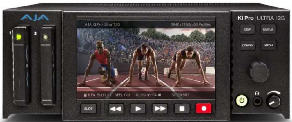
USER MANUAL Ki Pro Ultra 12G AJA
File Based Recorder/Player
text_image
AJA 1 2 67% SLOT SI REEL 001 01:09:05:04 ■ SCITK697 SILOT Ki Pro | ULTRA 12G DISP STATUS CONFIG MEDIA ΩInstallation and Operation Guide
Trademarks
AJA^® and Because it matters. are registered trademarks of AJA Video Systems, Inc. for use with most AJA products. AJA^TM is a trademark of AJA Video Systems, Inc. for use with recorder, router, software and camera products. Because it matters. is a trademark of AJA Video Systems, Inc. for use with camera products.
Corvid Ultra ^® , Io ^® , Ki Pro ^® , KONA ^® , KUMO ^® , ROI ^® and T-Tap ^® are registered trademarks of AJA Video Systems, Inc.
AJA Control Room™, KiStor™, Science of the Beautiful™, TruScale™, V2Analog™ and V2Digital™ are trademarks of AJA Video Systems, Inc.
All other trademarks are the property of their respective owners.
Copyright
Copyright © 2020 AJA Video Systems, Inc. All rights reserved. All information in this manual is subject to change without notice. No part of the document may be reproduced or transmitted in any form, or by any means, electronic or mechanical, including photocopying or recording, without the express written permission of AJA Video Systems, Inc.
Contacting AJA Support
When calling for support, have all information at hand prior to calling. To contact AJA for sales or support, use any of the following methods:
Telephone +1.530.271.3190
FAX +1.530.271.3140
Web https://www.aja.com
Support Email support@aja.com
Sales Email sales@aja.com
Contents
Notices 2
Trademarks 2
Copyright 2
Contacting AJA Support 2
Chapter 1 – Introduction .....5
Overview....5
Features 5
12G/6G SDI 5
Multi-Channel HD Recording 6
Ki Protect 6
Hardware....6
Software 7
Media Formatting Requirements 7
Ki Pro Ultra 12G Options 7
AJA Pak Media....7
AJA Pak Dock 8
AJA Fiber Modules 8
KPU-Shelf....8
Apple ProRes 422 and Apple ProRes 444 Advantages ....8
Avid DNxHD/HR Advantages 9
In This Manual 9
Chapter 2 – Ki Pro Ultra 12G at a Glance....10
Front Panel Controls. 10
Front Panel 10
Rear Panel Connectors 13
Connections 14
Power Connector 16
Storage 17
Formatting Media 17
Using Pak Media with Final Cut Pro and Premier Pro 17
Using Ki Pro Ultra 12G Media with Avid Media Composer ..... 18
Closed Captioning Support 18
Chapter 3 – Ki Pro Ultra 12G Installation. . . . . . . . . . . . . . . . . . . . . . . . . . . . . . . . . . . . . . . . . . . . . . . . . . . . . . . . . . . . . 19
Overview....19
What's In The Box? 19
Applying Power.... 19
Remote Network Control 20
Network Connections....20
TCP/IP Information You'll Need 21
Networking via DHCP 21
Networking Ki Pro Ultra 12G using a Static IP Address. . . . . . . . . . . . . . . 21
Networking Ki Pro Ultra 12G Using the Factory Default IP ..... 23
Controlling Ki Pro Ultra 12G From a Web Browser ..... 23
Installing Optional SFP I/O Modules. 23
Chapter 4 – Front Panel Operation ..... 25
Overview....25
Control Panel Operation 25
User Control Knob Functions 25
Overlay Display Content 26
Transport Mode (default) 28
Automatic 12G Signal Detection and Configuration....29
Recording a Clip. 29
Playing Back a Clip 31
Deleting Clips 32
Status Menus 32
Media Menus 35
Media Menu Parameters 35
Custom Clip Naming....42
Config Menus 44
Config Menu Parameters 44
Signal Routing Examples. 61
Chapter 5 – Browser Remote Control .....64
Overview. 64
Operations Unique to the Web UI 68
Playing, Jogging and Selecting Clips 68
Playlists 69
Gang Recording. 70
Data Transfer via LAN 72
Presets. 73
Updating Firmware. 75
Chapter 6 – Ki Pro Ultra 12G Accessories .....77
Overview. 77
Ki Pro Ultra 12G Handle. 77
KPU-Shelf 78
SFP Modules. 78
Appendix A – Specifications .....79
Ki Pro Ultra 12G Tech Specs 79
Dimensions 83
Appendix B – Safety and Compliance .....86
Warranty and Liability Information....95
Limited Warranty on Hardware. 95
Limitation of Liability 95
Governing Law and Language; Your Rights 95
Index. 97
Chapter 1 – Introduction
text_image
AIA AIA 50% Pro (20) 100% Pro (100% 100% 100% 100% 100% 100% 100% 100% 100% 100% 100% 100% 100% 100% 100% 100% 100% 100% 100% 100% 100% 100% 100% 100% 100% 100 100% 100% 100% 100% 100% 100% 100% 100% 100% 100% 100% 100% 100% 100% 100% 100% 100% 100% 100% 100% 100% 100% 100% 100% 100% Pro (1.77%) 123 OK Cancel OK OK OK OK OK OK OK OK OK OK OK OK OK OK OK OK OK OK OK OK OK OK OK OK OK OK OK OK OK OK OK OK OK OK OK OK OK OK OK OK OK OK OK OK OK OK OK OK OK OK AK AK AK AK AK AK AK AK AK AK AK AK AK AK AK AK AK AK AK AK AK AK AK AK AK AK AK AK AK AK AK AK AK AK AK AK AK AK AK AK AK AK AK AK AK AK AK AK AK AK ALK ALKOverview
Ki Pro Ultra 12G is a Multi-Channel Apple ProRes recorder offering up to 4-Channels of simultaneous HD recording, or in Single-Channel mode a 4K/UltraHD/2K/HD Apple ProRes® or Avid DNxHD® MXF recorder and player. Ki Pro Ultra 12G supports the latest connectivity, as well as large raster high frame rate workflows, including 4K 60p.
12G, 6G, 3G, 1.5G-SDI and fiber and full HDMI 2.0 digital video connectivity and a wealth of analog and digital audio connectivity answers any project's demand for efficient, powerful and flexible workflows.
Designed to be either portable or rack-mountable with half rack wide 2RU high dimensions, it's well suited for use in studio/truck environments in addition to on-set and even digital signage applications. The Ki Pro Ultra 12G is designed to meet the growing demand for 4K and UltraHD capable recorder products with full support for current HD projects.
Ki Pro Ultra 12G enables manageable large raster workflows with the efficiencies of Apple ProRes, supporting a broad range of video formats and frame rates recorded directly to AJA's proven and reliable Pak Media, offering the lowest cost per GB available today.
Next generation pristine UltraHD 60p and 4K 60p recording in Apple ProRes HQ is offered utilizing Pak 2000, Pak 1000, Pak 512 and Pak 256 SSD media, complete with full rollover capabilities from drive to drive. This ensures long recording times for the most demanding projects.
Remote playback can be obtained easily with full control via the RS-422 serial connection or through the simple and intuitive on unit menu system and through the Ki Pro Ultra 12G web interface.
Menus and images are beautifully rendered on a new high resolution LCD display enabling detailed playback and monitoring in all environments.
Features
12G/6G SDI
The Ki Pro Ultra 12G BNC 1 input and output connectors each support up to 12G SDI on a single link. The SDI Fiber 1 input and outputs also support 12G SDI video. When configured for a Single Encode Channel and selecting one of these video inputs or outputs, Ki Pro Ultra 12G becomes able to record and playback single-link 6G and 12G signals.
Multi-Channel HD Recording
Record 1, 2, 3 or 4-Channels of beautiful HD up to 1080p 50/60 in Apple ProRes simultaneously with Ki Pro Ultra 12G. Simplify your multi-camera productions by running up to four cameras per Ki Pro Ultra 12G and save power, space, time and effort on set, in the studio and when setting up OB trucks.
IMPORTANT: The Ki Pro Ultra 12G recording inputs must be genlocked together, or multi-channel recording and monitoring failures may occur.
Ki Pro Ultra 12G even allows independent profile support per channel in Multi-Channel mode; for example, select high resolution Apple ProRes HQ for high quality finishing and use a second input to record Apple ProRes (Proxy) for an efficient editing pipeline.
Starting with input 1, add channels as needed in order when utilizing like raster size and frame rate, and record your HD Apple ProRes files on the same AJA Pak Media. Ki Pro Ultra 12G even allows rollover to a second Pak Media for hours of uninterrupted multi-channel recording.
IMPORTANT: Multi-channel recording is only supported on Pak 2000, Pak 1000 (all versions), and on Pak 512 and Pak 256 (R1 or later).
Ki Protect
Ki Pro Ultra 12G includes Ki Protect, a feature that helps to ensure ProRes data integrity if a media drive is accidentally removed or loses power during recording. The Ki Protect feature automatically pre-allocates recording space on the media drive for video, audio and timecode when the record button is pressed. Whilst recording, the file header is then continuously updated every time new data is written. That way, the only loss that should be incurred is the last few frames that were in transit to the media drive to be recorded when the operation was interrupted. Frames that are already recorded will be preserved and are recoverable, providing greater piece-of-mind on set and in the studio.
Hardware
- Supports 12G, 6G, 3G and 1.5G-SDI BNC and Fiber input and output (Single Channel mode)
- Up to 4-Channels of simultaneous HD recording
- Apple ProRes 444 (XQ), Apple ProRes 444, Apple ProRes 422, Apple ProRes 422 (HQ), Apple ProRes 422 (LT), and Apple ProRes 422 (Proxy) implemented in hardware
- Avid DNxHR HQX, Avid DNxHR SQ, and Avid DNxHR LB—implemented in hardware
- Avid DNxHD HQX, Avid DNxHD SQ, and Avid DNxHD LB—implemented in hardware
- MXF with OP1A support for DNxHD encoded files, bringing true Avid MXF compatibility
• 12G-SDI input (1x BNC connector)
• 3G-SDI input (3x BNC connectors)
• 12G-SDI output (1x BNC connector)
• 3G-SDI output (3x BNC connectors)
• 12G-SDI Fiber or HD-BNC input (1x connector, optional SFP module)
• 3G-SDI Fiber or HD-BNC input (3x connectors, optional SFP modules)
• 12G-SDI Fiber or HD-BNC output (1x connector, optional SFP module)
• 3G-SDI Fiber or HD-BNC output (3x connectors, optional SFP modules)
• HD-SDI monitor output (1x BNC connector)
• HDMI v2.0 Input and Output
• 8-ch AES Audio Input (1/2x DB-25 TASCAM pinout)
• 8-ch AES Audio Output (1/2x DB-25 TASCAM pinout)
• 8-ch Analog Audio Input (1x DB-25 TASCAM pinout)
• 8-ch Analog Audio Output (1x DB-25 TASCAM pinout)
• LTC Input (1x BNC connector)
• LTC Output (1x BNC connector)
• Reference Loop (2x BNC connectors)
• RCA Audio output (2x mono RCA connectors)
• Headphone jack (1x 3.5mm Jack)
• 10/100/1000 Ethernet LAN (1x RJ-45 connector)
• RS-422 Machine control (1x DB9)
- 1280 x 720p TFT LCD display (for UI information and confidence monitoring)
- Dual 12 Volt AC/DC power converter included (2x 4-pin XLR connectors)
Software
- Internal web server for remote control configuration via LAN
- Both HFS+ and exFAT file systems supported
- Continuous rollover record only limited by the size of your media
- Capture and playback of CEA 708 Closed Captioning data as QuickTime movie tracks
- Download and upload of files via LAN
- 20 Preset registers for storing and recalling system preset configurations
- Alarms to alert users to conditions that may need attention
Media Formatting Requirements
The Ki Pro Ultra 12G records and plays Apple QuickTime ProRes 444, Apple ProRes 422 and DNxHD files to/from SSD media.
Files can be stored on the media using the HFS+ file system. This makes the media readable on any Mac OS computer natively (using the associated media reader) and PCs using 3rd-party software that can read HFS+ formatted drives (MediaFour's MacDrive for example).
Ki Pro Ultra 12G can also store files on media using the ExFAT file system, for native macOS and PC operation.
Ki Pro Ultra 12G Options
AJA Pak Media
Ki Pro Ultra 12G lets you record edit-friendly 4K, 2K, or HD files directly to removable AJA Pak Media. Once removed from the Ki Pro Ultra 12G, the Pak Media can be inserted in the AJA Pak Dock which connects directly to your computer via Thunderbolt or USB 3.0, allowing you to rapidly transfer ProRes or DNxHD files that are ready for use immediately in your non-linear editing system.
NOTE: When you order your Pak Media you can choose the formatting, either HFS+ or ExFAT.
AJA Pak Options
The Pak 256, Pak 512, Pak 1000, and Pak 2000 options are high-capacity Solid State Drives encased in a protective housing with rugged connection engineered to handle the rigors of repeated use in the field.
NOTE: The newer Pak 256 and Pak 512 (R1 and above), and the Pak 1000 and Pak 2000 media support recording all formats and frame rates up to and including 4K/UltraHD 50, 59.94,60 at ProRes 422 (HQ). Legacy Pak 256 (R0) and Pak 512 (R0) media have slightly lower capabilities, and are able to record up to 4K/UltraHD 30.
AJA Pak Dock
The AJA Pak Dock option is an external media reader with Thunderbolt™ and USB 3.0 connections for fast transfer of media to a host computer.
AJA Fiber Modules
Fully integrated fiber inputs and outputs means Ki Pro Ultra 12G can be integrated directly to a dedicated fiber network alongside many other fiber products.
See https://www.aja.com/software/configurator for an online tool you can use to select compatible SFP modules.
KPU-Shelf
Ki Pro Ultra 12G can be mounted side by side using the optional KPU-Shelf for rackmount applications. Using the four channel HD recording capability and front panel quad display, two rack mounted Ki Pro Ultra 12G units can record and monitor eight HD signals in only two rack units of space.
Apple ProRes 422 and Apple ProRes 444 Advantages
Captured media using Apple ProRes 422 or Apple ProRes 444 is virtually indistinguishable from uncompressed HD/2K/4K sources. Better yet, Apple ProRes maintains the quality during editing, surviving multiple encoding/decoding generations without degradation. It was designed by Apple specifically for editing. Some of the advantages include:
- Resolution support for 4096-by-2160 (4K), 3840-by-2160 (UltraHD), 2048-by-1080 (2K), 1920-by-1080 (HD), and 1280-by-720 (HD).
- 4:2:2 or 4:4:4 chroma sampling. Provides precise compositing and blending at sharp saturated-color boundaries.
- 10/12-bit sample depth. Preserves subtle gradients of 10/12-bit sources (perfect for green-screen compositing, graphics or color correction) with no visible banding artifacts.
- Intra-frame encoding. Ensures consistent quality in every frame and no artifacts from complex motion.
- Variable bit-rate (VBR) encoding. "Smart" encoding analyzes the image and allocates more bits to complex frames.
- Low data rate requirements make for more storage options and require less drive space to store high quality video.
Avid DNxHD/HR Advantages
Quality using Avid DNxHD and DNxHR is excellent— high quality encoding without high bandwidth requirements. Avid DNxHD and DNxHR were designed for non-linear post-production and broadcast to withstand multi-generational processing.
• Full-size 4K, UltraHD, 1920-by-1080 and 1280-by-720 resolutions.
• 4:2:2 chroma sampling.
- 10-bit sample depth (DNxHR HQX or DNxHD HQX), or 8-bit.
NOTE: Ki Pro Ultra 12G can accept 12-bit inputs but processes and encodes at 10-bit.
- Every frame of encoding is independent.
- Constant bit-rate (CBR) encoding.
- Low data rate requirements.
Table 1. Data Rates (Mb/sec) for DNxHR and DNxHD Formats
| Codec | Format | 23.98 | 24 | 25 | 29.97 | 50 | 59.94 | |
| DNxHR | HQX | 4K | 711 | 711 | 741 | 880 | ||
| UHD | 666 | 666 | 695 | 833 | ||||
| SQ | 4K | 470 | 470 | 490 | 587 | |||
| UHD | 441 | 441 | 459 | 551 | ||||
| LB | 4K | 146 | 146 | 152 | 183 | |||
| UHD | 137 | 137 | 143 | 171 | ||||
| DNxHD | HQX | 1080p | 175 | 175 | 185 | 220 | 365 | 440 |
| 1080i | 185 | 220 | ||||||
| 720p | 175 | 220 | ||||||
| SQ | 1080p | 115 | 115 | 120 | 145 | 240 | 290 | |
| 1080i | 120 | 145 | ||||||
| 720p | 115 | 145 | ||||||
| LB | 1080p | 36 | 36 | 36 | 45 | 75 | 90 | |
NOTE: Blank format/frame rate combinations are not currently supported.
NOTE: 4K, UltraHD, and SD video encoding using Avid DNxHD is not currently supported.
In This Manual
Chapter 1 provides an overview of hardware and software features and options.
Chapter 2 gets you started with Ki Pro Ultra 12G, introducing the front panel controls and rear connector features.
Chapter 3 gives detailed installation information.
Chapter 4 provides complete instructions for operating the Ki Pro Ultra 12G from the front-panel controls and LCD display.
Chapter 5 discusses remote web browser control of Ki Pro Ultra 12G via Ethernet.
Chapter 6 provides details of AJA accessories available.
Appendix A lists specifications.
Appendix B provides safety and compliance information.
Warranty Information & Index complete the manual.
Chapter 2 – Ki Pro Ultra 12G at a Glance
Front Panel Controls
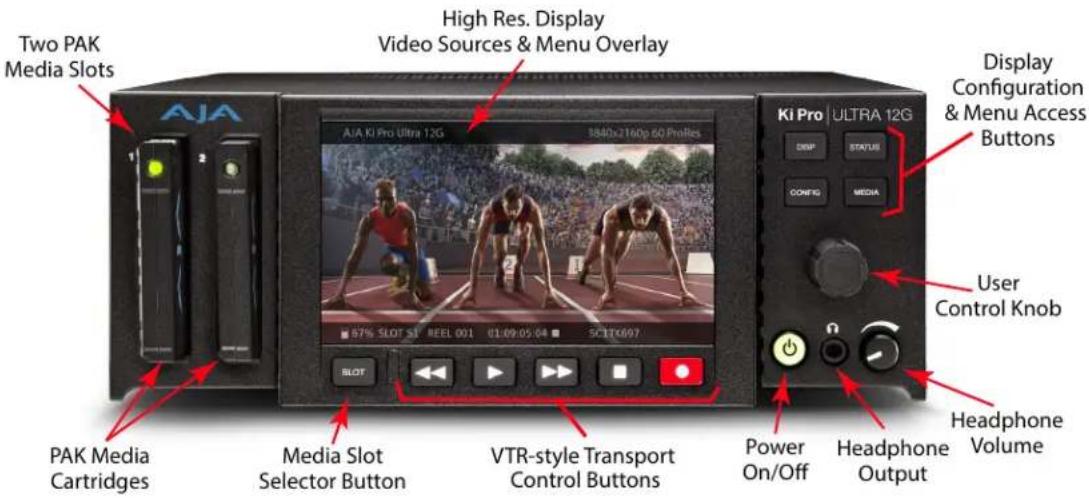
Figure 1. Ki Pro Ultra 12G Operator Side Controls
text_image
Two PAK Media Slots High Res. Display Video Sources & Menu Overlay AJA KI Pro Ultra 12G 3840x2160p 60 ProRes Display Configuration & Menu Access Buttons Ki Pro ULTRA 12G User Control Knob PAK Media Cartridges Media Slot Selector Button VTR-style Transport Control Buttons Power On/Off Headphone Output Headphone Volume
Caution! The AJA Ki Pro Ultra 12G contains a lithium battery soldered in place permanently (it is not user replaceable). If you ever dispose of the Ki Pro Ultra 12G, ensure you follow local regulations for safe disposal. The lithium battery shall not be exposed to excessive heat, such as sunlight or fire.
Front Panel
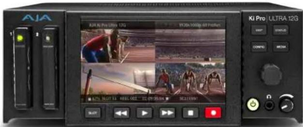
The Ki Pro Ultra 12G front panel includes:
- Power button
- Two Pak Media slots and a Slot Selector button
- Transport controls
- Menu selection buttons
• Headphone volume control and headphone jack - Multi-purpose User Control Knob for jog and selection functions
- Large 1280 x 720 TFT LCD display with Video Monitor and Menu/Status Overlays
Power ON/OFF Button
Controls system power ON/OFF and shows when power is ON (when illuminated) or OFF.
NOTE: When power is first applied to Ki Pro Ultra 12G, the unit powers up immediately (without pressing the button). This facilitates a quick return to operation if there is a power interruption.
NOTE: Upon power up with both slots populated, Slot 1 is the initial storage system accessed by Ki Pro Ultra 12G.
In normal operation to turn power on, press the button once. It isn't necessary to press hard—it's a "soft" button sensed by the processor inside. Pressing the button will begin power-up and display start-up progress on the alphanumeric display.
To power down, press and hold the power button down for 3 seconds while the display counts down. This process prevents accidental power-off during normal operation. You can abort the power-down process by simply removing your finger from the power button before the 3 seconds have elapsed.
SLOT Button
The SLOT button serves two purposes. It selects which media slot is accessed by the system (either Slot 1 or 2) and is used to unmount the currently selected media. When the Pak card LED is extinguished, it is unmounted and can be removed.

Caution! Always use the SLOT button to unmount media or it may be damaged when removed.

Caution! Pushing the slot button cycles between unmounting media and selecting media. This function is only active when in transport STOP mode. If it is not highlighted, press the stop button. After you select a slot, the system returns to the last selected clip and timecode for that slot. If the media has been changed since the slot was last selected (media physically removed or replaced), the "first" clip on the media will be "cued" to its start point. If inserted media has any issues, additional prompts may be displayed as appropriate such as: "Warning: Backup and Reformat" or "Warning: Media Unformatted.

Caution! Removing media with the Slot LED highlighted, or while flashing, can result in corrupted media or potential damage to the media.
Transport Control Buttons
The transport buttons are always active.
STOP - The square symbol STOP button has a dual function. When playing back a clip (PLAY, FFWD, or REV) the first push of STOP acts as a "pause" mode: the playback is paused, the current point of the clip is displayed, and the STOP button flashes. A second push of STOP completely stops the playback and directs Ki Pro Ultra 12G outputs into an "idle" mode (the currently selected inputs are passed to the outputs). To determine at a glance if the STOP button is in a "pause" mode, note that the stop button will flash if media playback is paused. The STOP button is fully illuminated in "stop" mode.
PLAY > - Press PLAY to begin forward playback of the current clip at normal speed.
RECORD- Press the round red RECORD button to begin recording. Once in RECORD mode, all other transport buttons are locked-out except the STOP button.
FFWD >> - Press FFWD to begin fast playback of the current clip at 2x speed. Successive pushes increase the speed to 4x, 8x, and 16x. (Pushing the button after 16x speed is reached has no further effect.) When fast-forwarding, audio is muted.
REV << - Press REV when not highlighted to begin playback of the current clip in reverse at 1x speed. Successive pushes increase the speed to 2x, 4x, 8x, and 16x. (Pushing the button after 16x speed is reached has no further effect.) When playing in reverse, audio is muted for all speeds.
DISP Button
Use the display button to toggle video overlay display modes. Sequential presses of the button step through these display modes:
- No overlay – display is video monitor only
- Top and bottom status overlay
- In Multi Channel mode only, smaller audio meter overlays for all current record channels are shown, along with the top and bottom status overlay
- A larger headphone audio VU meter overly is shown, along with the top and bottom status overlay and, if in Multi Channel mode, the smaller record channel audio meters.
The display button can be used to hide the Config or Status overlay if it is active.
User Control Knob
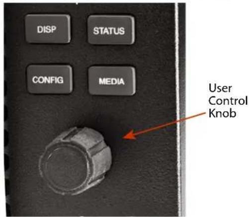
The User Control Knob on the right side of the Ki Pro Ultra 12G front panel is used to scroll through and select menu items. After scrolling to, and highlighting a menu item of interest, push the knob to select. To pop out of a selected menu item, use the rotator knob to highlight EXIT and push the knob to return to the top level.
When not in a configuration mode and media is mounted with clips available, you can use the selection knob to scroll through the clips. Press the knob once to enable JOG mode to step through the clip a frame at a time.
STATUS Button
When it is not highlighted, you can press the STATUS button to display the status overlay. Status includes video input, format, record format, and audio setup information. Once selected, the selector knob can be rotated to display either the Status or ALARM tab. If any ALARMS or WARNINGS are active, they will be displayed under the ALARMS tab.
When it is highlighted, pressing the STATUS button hides the Status overlay.
A blinking Status button indicates Alarms are present. Press the STATUS button to immediately display the ALARM tab.
NOTE: When necessary, you can initiate a "safeboot" of the Ki Pro Ultra 12G by holding in the STATUS button while powering up.
CONFIG Button
When it is not highlighted, you can press CONFIG to access the Ki Pro Ultra 12G configuration menu overlay. If the transport is active—video is playing or being recorded—you will be prompted to stop the transport before entering configuration mode. Use the User Control Knob to respond to system prompts by rotating and pushing to select. Once in configuration mode the User Control Knob can be rotated to scroll the menu system. Push the User Control Knob to enter a selected menu, scroll through the selections, push to select a setting. To leave a menu, scroll to Exit and press the knob.
MEDIA Button
When it is not highlighted, you can press the MEDIA button to enter the Media menu. Pressing MEDIA when it is highlighted will turn Off the Media menu (returning to the default Transport menu). The Media menu can only be entered from the transport STOP mode. The Media menu remembers which parameter it is set to when exited and will return to that same parameter when the menu is re-entered.
Headphone Volume Knob
To adjust headphone listening level, press the knob inward and the knob will then pop out for easy adjustment.
Displays and Indicators
Alphanumeric and Graphics LCD Display
This display shows menus, status, alerts and other information. Some words in the menus may be truncated to fit the display limits. The LCD displays not only UI information, but also a scaled version of the incoming signal or playback of recordings. When the monitoring outputs are set to crop a signal to 1920x1080, a graticule is applied to the scaled image on the LCD to alert the user.
VU Meters
A video overlay is provided on the LCD to display audio VU meters. Meters are color-coded to report signal strength:
- Green - audio source signal level is in the "safe" area (no clipping). Vertically, the green LEDs also show the signal strength, so you can see if the signal level is low. Generally, it's preferred to have the signal near the top of the green or even occasionally peaking into the yellow LEDs.
- Yellow - audio source signal levels are at the peak edge of the safe area before clipping will occur.
- Red - audio source amplitude is too hot and the signal is clipping at its signal peaks. You should reduce the input gain at its source (camera, mixer or source equipment supplying the signal).
Slot LED Status Indicator
These LED 1 and 2 states indicate the status of the media slots, S1 and S2:
• LED highlighted/on: selected media
- LED not highlighted/off: inactive media, okay to eject or no media inserted
• LED flashing: recording in progress
Headphone Jack
1/8" (3.5mm) miniature stereo TRS connection for standard stereo headphones.
Rear Panel Connectors
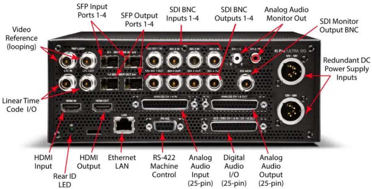
The functions of Ki Pro Ultra 12G inputs and outputs depend on the operational mode. Ki Pro Ultra 12G active input (the one to be recorded) is selected by front panel or web browser control. Ki Pro Ultra 12G outputs are active all the time.
Figure 2. Ki Pro Ultra 12G Connectors
text_image
Video Reference (looping) Linear Time Code I/O HDMI Input Rear ID LED SFP Input Ports 1-4 SFP Output Ports 1-4 SDI BNC Inputs 1-4 SDI BNC Outputs 1-4 Analog Audio Monitor Out SDI Monitor Output BNC Redundant DC Power Supply Inputs HDMI IN LTC IN LTC OUT 1-2 SDI 800 OUT 3-4 12G SDI 1 IN SDI 2 IN SDI 3 IN SDI 4 IN CH 1 / L CH 2 / P KI PRO ULTRA 12G 12V - 18V ANALOG CH 1.8 IN ANALOG CH 1.8 OUT RS-422 AES / EBU CH 1.8 IN / CH 1.8 OUT Analog Audio Input (25-pin) Digital Audio I/O (25-pin) Analog Audio Output (25-pin)Connections
- Reference video loop for connection to genlock video or sync
• LTC Input and Output (2x BNC) - HDMI v2.0 compatible input and output up to 4K/UltraHD 50/59.94/60 4:2:2 YCbCr or 4:4:4 RGB with up to 8-channel embedded audio
• 10/100/1000 Ethernet LAN - Dual-channel Fiber Inputs 1-4/Outputs 1-4, with 12G SDI support on the first input and output port
- SDI Input and Output BNCs, with up to 16-channel embedded audio (8x BNC), with 12G SDI support on the first input and output BNC
• HD-SDI Monitor Output (1 BNC) with embedded audio.
• Balanced 8-channel Analog Audio Input via one DB-25 TASCAM pinout
• Balanced 8-channel Analog Audio Output via one DB-25 TASCAM pinout - AES EBU 8-channel Audio Input and Output via one DB-25 TASCAM pinout
• RS-422 DB-9 Machine Control Interface (Sony 9 Pin protocol)
• Dual Mono Analog Audio Output via 2 RCA Connectors
Ref Loop
The Reference Loop BNCs accept an output timing reference signal. The reference can be analog SD blackburst or HD tri-level sync. Examples of permissible reference video input signals:
- 525 Color Black
• 625 Color Black
• 1080i Tri-level Sync - 720p Tri-level Sync
The 2 BNCs are a passive loop: one BNC is for the Input, and the remaining BNC can be connected to another piece of equipment in the reference chain or terminated.
NOTE: For proper operation the input reference signal must be stable and properly terminated using a 75-ohm terminator on either the unused loop connector or the last piece of downstream equipment to which the reference video is connected.
LTC Timecode I/O
Two BNCs provide connections to the house LTC timecode generator or source. Connections are high impedance. One BNC is for input and the other for output.
SFP In/Out (optional)
Four dual SFP cages (two input, two output) accept optional SFP modules. The first ports support 12G SDI input and output. All four SFP I/O ports also support 3G SDI operation and embedded 24-bit digital audio.
NOTE: Which audio channels are embedded to the SDI Outputs is determined by the audio embedding settings being used for the Ki Pro Ultra 12G audio input, or the audio channels of the clip being played back.
SDI Inputs and Outputs
Eight BNC connectors (four inputs and four outputs) are provided. The first BNC input and output pair supports 12G-SDI video. All eight BNCs also support 3G SDI operation and embedded 24-bit digital audio.
IMPORTANT: During recording, an SDI BNC output signal is not a pass-through E-to-E signal of the input.
SDI Monitor Out
One SDI Monitor Out connector provides for monitoring compatible video and multi-channel embedded audio.
Analog Audio Monitor Output
Two RCA connectors provide line level analog audio output, carrying the same signal sent to the front panel headphone output.
HDMI Input and Output
Two HDMI connectors (one input and one output) support HDMI video and multi-channel embedded audio, and use standard HDMI cables. HDCP is not supported on the input or output.
NOTE: Which audio channels are embedded to the HDMI Output is determined by the audio embedding settings being used for the Ki Pro Ultra 12G audio input, or the audio channels of the clip being played back.
HDMI formats supported
• 720p 50, 59.94, 60
• 1080i 25, 29.97, 30
• 1080p 23.98, 24, 25, 29.97, 30, 50, 59.94, 60
• 2Kx1080p 23.98, 24, 25, 29.97, 30, 50, 59.94, 60
• Ultra HD (3840x2160p) 23.98, 24, 25, 29.97, 30, 50, 59.94, 60
• 4K (4096x2160p) 23.98, 24, 25, 29.97, 30, 50, 59.94, 60
NOTE: When using the Ki Pro Ultra 12G HDMI connection and attaching it to any HDMI audio or video accessory, you must use a ferrite-beaded HDMI cable, HH-28F-06, between the HDMI output port of the Ki Pro Ultra 12G and the HDMI accessory to maintain regulatory compliance.
Ethernet
An RJ-45 connector provides a 10/100/1000 Ethernet port for connecting Ki Pro Ultra 12G directly to a computer or Ethernet hub or switch for connecting to a LAN. Ki Pro Ultra 12G is compatible with CAT-5 straight-through or cross-over Ethernet cables, automatically detecting which is used. Once connected and properly configured, Ki Pro Ultra 12G can then be controlled by a web browser on the LAN.
8-Channel Balanced Analog Audio I/O
Two DB-25 TASCAM pinout, one input and one output, provide 8-channel balanced audio. Audio is high-quality 24-bit A/D input and D/A output at 48kHz. Level adjustments are made via software. Software level adjustments for analog audio (parameter 4.1) apply to balanced audio.
AES Digital Audio I/O
AES digital audio connections consist of one DB-25 TASCAM pinout for 8 channels of input and 8 channels of output.
RS-422 Connector
Ki Pro Ultra 12G offers a 9-pin serial port that may be used with compatible RS-422 devices.
IMPORTANT: Not all RS-422 devices have been tested with Ki Pro Ultra 12G, so AJA cannot definitively say which devices may or may not communicate as expected with Ki Pro Ultra 12G when operated under RS-422 remote control.
For details on using RS-422 machine control setup, see "35.2 Remote Control" on page 55.
Power Connector
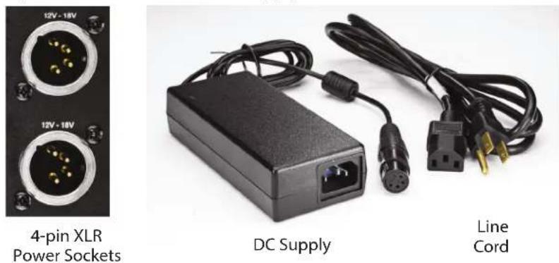
On the back of Ki Pro Ultra 12G are two standard 4-pin male XLR connectors for supplying 12-Volt DC power to the unit. You can use either the supplied AC Adapter or furnish your own battery source. Since the connector is an industry standard pinout, choices are varied and flexible. Many 3rd party vendors offer products using this standardized power connector.
• Pin 1:
- Pin 4: +
- Pins 2 and 3: not used

Caution! Ki Pro Ultra 12G has no user-serviceable parts. To remove power from the unit, remove the 4-pin XLR power connector to ensure disconnection. Refer all servicing to qualified service personnel. Servicing is required when the device has been damaged in any way, such as power-supply cord or plug is damaged, liquid has been spilled or objects have fallen into the device, the device has been exposed to rain or moisture, does not operate normally, or has been dropped
Ki Pro Ultra 12G can record to Pak Media, a form of removable SSD media. The media is formatted either as HFS+ (native to the Mac OS file system,) or ExFAT (suitable for PCs. Using the Pak Dock, Pak Media with the correct formatting can be directly mounted on a Mac or PC for immediate editing and file access.

Caution! Failure to properly mount or dismount media, or an unexpected loss of power while recording, can result in an unrecoverable data loss.
Formatting Media
Pak Media is provided preformatted. However, you may want to format media that has already been used, or name media and format it during your shoot. To format Pak Media, the media must be inserted into a Media Slot. Once the media is mounted:
- Press the MEDIA button.
- Rotate the User Interface Control Knob until you see the menu parameter 16.0 File System Formatting:
- Push in the User Interface Control Knob.
- Rotate the User Interface Control Knob to choose the type of file system formatting (HFS+ or ExFAT).
- Push in the User Interface Control Knob.
- Rotate the User Interface Control Knob until you see the menu parameter 16.2 Format Media:
- Push in the User Interface Control Knob.
- Rotate the User Interface Control Knob until "OK" appears. Push in on the User Interface Control Knob.
- Press and hold in the User Interface Control Knob and formatting will begin.
You may select any other key to abort the format operation should you inadvertently enter this menu parameter. The confirmation process used for formatting media helps you avoid accidentally formatting media.
WARNING: Once you have formatted media, you will not be able to recover recordings that were previously made on the media. Always be sure that any media you format has been properly backed up prior to formatting
Ki Pro Ultra 12G will display formatting progress and will display a completion confirmation when done. Press any key to clear the completion prompt.
Using Pak Media with Final Cut Pro and Premier Pro
When Ki Pro Ultra 12G media is removed and connected to a computer via the AJA Pak Dock, the media will mount as a normal HFS+ or ExFAT file system. The Reel NAME parameter is the name of the media that will appear when the media is mounted.
Once the media is mounted, each clip recorded by Ki Pro Ultra 12G will be a file on its file system, which (depending on the file type) can be opened directly in non-linear editors such as Final Cut Pro, Adobe Premiere Pro, etc. Compatible clips will be instantly ready to edit because they were recorded as ProRes or DNxHD QuickTime files, or as native DNxHD files.
Using Ki Pro Ultra 12G Media with Avid Media Composer
Ki Pro Ultra 12G can create native DNxHD and DNxHR files, and can also create DNxHD QuickTime wrapper files. Native DNxHD files on Pak Media can be accessed, opened and edited directly in Avid Media Composer without transcoding.
To use the Avid DNxHD QuickTime files produced by Ki Pro Ultra 12G in Avid Media Composer, AJA recommends using the "Link to AMA File(s)" feature provided in Avid Media Composer.
NOTE: While Ki Pro Ultra 12G QuickTime files can be directly accessed from Avid Media Composer via AMA for editorial, AJA advises transferring/copying media to a local drive or disk array for editing.
NOTE: Avid DNxHD QuickTime files produced on the Ki Pro Ultra 12G are designed for use with Avid Media Composer. While these QuickTime files can be read in a variety of other non-linear edit systems (when the appropriate Avid QuickTime codec package has been installed), AJA cannot verify the behavior or performance of DNxHD QuickTime files in these other non-linear edit systems.
Closed Captioning Support
With ProRes files, Ki Pro Ultra 12G operating in Single Channel mode supports the capture and playback of CEA-708 Closed Captioning data as QuickTime movie tracks. Ki Pro Ultra 12G extracts CEA-708 (including 608 within 708) packets contained in the vertical ANC data which is embedded in the SDI input (BNC or Fiber) signal. The packets are processed and inserted into a QuickTime track (CLCP) as part of the recorded QuickTime container. This track is created automatically if the CEA-708 packets are present in the VANC of the input SDI signal. No user configuration is required.
On playback, Ki Pro Ultra 12G will process the QuickTime container file, process the CLCP track if present and insert/embed closed captioning data on the SDI 1 output (BNC or Fiber) VANC.
When in Idle or Record mode, the Ki Pro Ultra 12G Status display indicates when closed captioning data is present on the input signal. In playback mode, the Status display indicates if CC data is being inserted.
Closed captioning is not supported on the Ki Pro Ultra 12G HDMI inputs/outputs, or the SDI monitor output, or when operating in Multi Channel mode.
Chapter 3 – Ki Pro Ultra 12G Installation
Overview
This section describes set up and installation of Ki Pro Ultra 12G. Choices you will make include how Ki Pro Ultra 12G will be controlled (front panel or Ethernet and web-browser) and the physical system requirements for your application.

Caution! Do not install near any heat sources such as radiators, heat registers, stoves, or other apparatus (including amplifiers) that produce heat

Caution! Do not block any ventilation openings. Install in accordance with the manufacturer's instructions.
What's In The Box?
When you unpack your Ki Pro Ultra 12G, you'll find the following components:
• Ki Pro Ultra 12G Recorder
- AC Adapter 110/220 with industry standard 4-pin XLR connector for powering the Ki Pro Ultra 12G. A standard North American line cord with 3-prong plug is included.
- Handle Installation Kit
Please save all packaging for shipping the Ki Pro Ultra 12G should you need to do so.
Applying Power
The following Warnings are provided as good practices and should always be considered when Ki Pro Ultra 12G is used in a desktop application.

Caution! Do not defeat the safety purpose of the polarized or grounding-type plug. A polarized plug has two blades with one wider than the other. A grounding type plug has two blades and a third grounding prong. The wide blade or the third prong are provided for your safety. If the provided plug does not fit into your outlet, consult an electrician for replacement of the obsolete outlet.

Caution! Since the Mains plug is used as the disconnection for the device, it must remain readily accessible and operable.

Caution! Protect the power cord from being walked on or pinched particularly at plugs, convenience receptacles, and the point where they exit from the device..

Caution! Unplug this device during lightning storms or when unused for long periods of time.
Using AC Power
To begin using Ki Pro Ultra 12G, plug the 4-pin XLR on the supplied AC adapter into the XLR power socket on the rear of Ki Pro Ultra 12G. Then plug the AC adapter line cord into 110 VAC or 230 VAC (the supply is auto sensing). Two power supplies can be used for redundancy.
NOTE: When connected to power, Ki Pro Ultra 12G will immediately begin the power-up procedure. This automatic start-up allows the unit to return to operation as soon as an unexpected power interruption is corrected.
Figure 3. Ki Pro Ultra 12G Power Supply Connections
text_image
12V - 18V 12V - 18V 4-pin XLR Power Sockets DC Supply Line CordUsing DC Power
To run Ki Pro Ultra 12G on DC power, plug a 3rd-party industry standard 12 Volt battery pack with a 4-pin female XLR connector into the power connector on rear of the Ki Pro Ultra 12G. The battery should be capable of supplying a sustained max current as supplied by the AC Adapter provided. See "Appendix A Specifications" for more information.
NOTE: To operate Ki Pro Ultra 12G properly, batteries should not have voltage lower than 12 volts and should not have voltage that exceeds 18 volts.
Ki Pro Ultra 12G is a low-wattage device so many batteries can power it for several hours at a time. Ki Pro Ultra 12G displays a "Near undervolt" warning prompt to help you stop recording before battery failure. We also recommend the use of batteries with metering or remaining power indications. When possible, for very long recordings, use the supplied AC power supply instead of battery power. Two power supplies can be used for redundancy
Remote Network Control
Network Connections
Ki Pro Ultra 12G can be networked to a computer using a single CAT-5 Ethernet cable (straight or cross-over) or using an Ethernet 10/100/1000 local area network (LAN) connection to the Ethernet RJ-45 connector.
If connecting via a LAN, connect the Ki Pro Ultra 12G Ethernet connector to a LAN hub or switch. A LAN is a shared network that includes other Ethernet devices all attached via a hub or digital switch. LANs may be divided into zones, and devices on a LAN may have fixed or dynamically assigned (DHCP) IP addresses. Before connecting Ki Pro Ultra 12G to the LAN, talk to your network administrator to find out how they want it connected (static IP or DHCP).
TCP/IP Information You'll Need
If your LAN has a DHCP server that assigns IP addresses dynamically, you don't have to configure anything (Ki Pro Ultra 12G defaults to DHCP). If your IT administrator prefers an assigned IP address that is fixed (called a "static IP"), get the IP address and you will enter it in the "IP Config parameter." If your LAN requires static IP addresses, also ask your IT administrator for the Subnet Mask and default gateway IP address (your LAN's Internet router). DHCP or via a static IP addressing are discussed in the following two topics.
Networking via DHCP
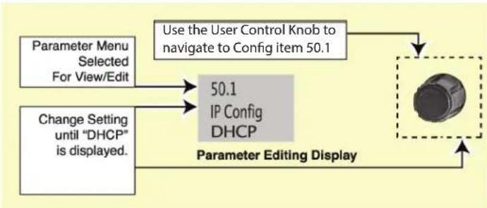
The default configuration (from the factory) automatically looks for a DHCP server to issue an IP address. As long as your network has a DHCP server (usually part of your router), you need to do nothing other than plug the Ki Pro Ultra 12G into the net. If you need to manually select DHCP, use the User Control Knob to navigate to the parameter50.1 IP Config, press the knob to activate the menu list, scroll to DHCP and press the knob again to select it.
flowchart
graph TD
    A["Parameter Menu Selected For View/Edit"] --> B["50.1"]
    C["Change Setting until "DHCP" is displayed."] --> B
    B --> D["IP Config DHCP"]
    D --> E["Parameter Editing Display"]
    E --> F["Use the User Control Knob to navigate to Config item 50.1"]
Here are the steps to communicate with Ki Pro Ultra 12G after choosing the DHCP selection:
- Use the User Control Knob to navigate to parameter 50.2. Make note of the DHCP supplied IP address shown to enter in your browser (Step 2).
- With your laptop or desktop computer DHCP enabled and connected to the same LAN, type the IP address from step 1 into the browser address bar. You should now see Ki Pro Ultra 12G browser status screen.
If Ki Pro Ultra 12G cannot get an address from the DHCP server, it will automatically drop back to a preset factory IP address of 192.168.0.2. If this happens, you can follow the steps below:
- Set the computer's Ethernet IP address to 192.168.0.n (where n is not 2).
- Set the computer's Subnet mask to 255.255.255.0 (most computers default to the proper netmask when the address is set).
- Run a browser on the computer and type 192.168.0.2 (the factory fallback IP address). You should now see Ki Pro Ultra 12G browser status screen.
NOTE: If Ki Pro Ultra 12G fails to find a DHCP server via its network connection, it will fall back to using the factory default static IP of 192.168.0.2—or whatever IP address you've previously defined. AJA recommends you define a Static IP address with parameter 50.2 so you'll be prepared in the event your DHCP server fails.
Networking Ki Pro Ultra 12G using a Static IP Address
To set a static IP address for Ki Pro Ultra 12G, you'll have to make some simple Parameter menu selections. The illustration below shows the four menu selections you need to make, while entering the information provided to you by your IT administrator (as discussed earlier).
Figure 4. Configuring Ki Pro Ultra 12G with a Static IP Address
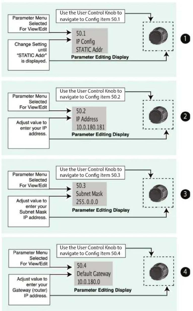
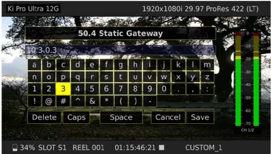
NOTE: For parameters 50.2, 50.3, and 50.4, you will be setting IP addresses using the User Control Knob and the Alphanumeric Keypad. Then you will click on SAVE to keep your entries.
Figure 5. Ki Pro Ultra 12G User Interface Alphanumeric Keypad
text_image
Ki Pro Ultra 12G 1920x1080i 29.97 ProRes 422 (LT) 50.4 Static Gateway 10.3.0.3 a b c d e f g h i j k l m n o p q r s t u v w x y z 1 2 3 4 5 6 7 8 9 0 . , : : ! @ # ^ & * ( ) - Delete Caps Space Cancel Save 34% SLOT S1 REEL 001 01:15:46:21 CUSTOM_1Networking Ki Pro Ultra 12G Using the Factory Default IP
If you don't want to use DHCP to network Ki Pro Ultra 12G and also don't want to set your own static IP address, you can simply use a Default setting to use a factory setting of 10.65.74.65. This is useful for quickly connecting directly to a laptop or computer. Here are the steps to set this up:
- Use the User Control Knob to navigate to parameter "50.1 IP Config", push the knob to enter the menu, then scroll to select "Default".
- Set your laptop or desktop computer Ethernet IP address to 10.m.n.m (where m is not 65 and n is not 74).
- Also on the computer, set the Subnet mask to 255.0.0.0 (most PCs default to the proper netmask when the address is set—so you may not have to change it).
- Run a browser on the computer and type 10.65.74.65 (the Default factory IP address). You should now see Ki Pro Ultra 12G' browser status screen.
Controlling Ki Pro Ultra 12G From a Web Browser
To control Ki Pro Ultra 12G from a web browser on a network attached computer, you must enter Ki Pro Ultra 12G's IP address as a URL in the browser. For example, if Ki Pro Ultra 12G's IP address were 10.0.6.31, you would then type into the web browser: http://10.0.6.31
This topic is explained in greater detail in "Chapter 5 Browser Remote Control" on page 64
Installing Optional SFP I/O Modules
The optional AJA SFP I/O modules are purchased separately from the Ki Pro Ultra 12G. Install the optional SFP I/O modules by inserting them into the rectangular cages on the back panel with the electrical connectors facing downward. Press gently but firmly until the modules seat in the inside connectors.
You must remove any connected fiber or coaxial cables from the SFP modules before you remove the modules from the Ki Pro Ultra 12G. Pull down the SFP lever to free the module before you withdraw the module from the cage.
For additional installation and operation details, see the instructions provided with the SFP modules.
Chapter 4 – Front Panel Operation
text_image
AIA KIA Ki Pro Ultra 12G 10.25m 10000p 60 PaRhet Ki Pro ULTRA 12G SHIFT CHANGE COMPO MOMA S/375 SLOT 51 REEL-002 - IZ 09:05:04 M SE211897 SLATY OKOverview
There are two ways to control Ki Pro Ultra 12G—from the front panel or remotely from a web browser connected via the Ethernet RJ-45 connector. This chapter discusses controlling Ki Pro Ultra 12G from its front panel. See "Chapter 5 Browser Remote Control" on page 64 for information about web browser operation.
Control Panel Operation
There are two basic front panel modes:
- Transport (default mode) - PLAY, STOP, FFWD, REV, REC. These functions are active at all times. By default the unit starts in a "record standby" or "transport idle" state.
-
Display - when you press the display button, an overlay is placed on the LCD screen. When you push one of the remaining menu buttons (Status, Config, or Media) Ki Pro Ultra 12G will display:
-
Status/Alarm reports
- Configuration menus
• Media formatting operations
Display Button Sequence
Press the Display button twice to bring up audio VU meters. Pressing a third time brings up the last menu selected. Press again to turn the overlay off.
User Control Knob Functions
Transport Mode Operations
Transport mode is the default mode—it controls basic functions of PLAY, STOP, FFWD, REV, etc. In the Transport mode, you can turn the User Control Knob to cycle through the clips in the currently selected storage slot and push the knob in once to enter JOG mode which allows single-stepping through frames of the clip forward or backward.
Display Mode Operations
In Status, Config, and Media modes, you use the User Control Knob to scroll through menu items (rotating) and make selections (pressing the knob).
Figure 6. Ki Pro Ultra 12G User Control Knob
text_image
DISP STATUS CONFIG MEDIA User Control KnobOverlay Display Content
Initial Overlay
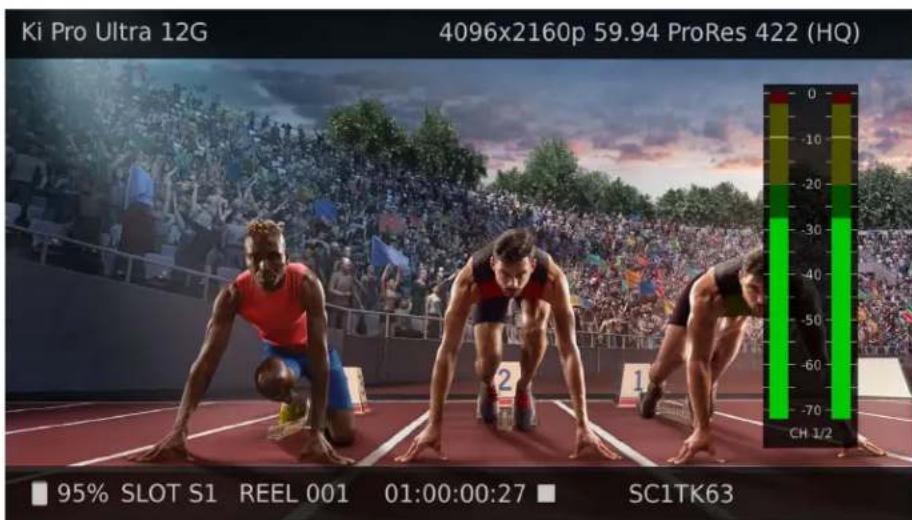
The figure below shows an overlay display with video content behind.
Figure 7. Display Overlay with Clip Shown
text_image
Ki Pro Ultra 12G 4096x2160p 59.94 ProRes 422 (HQ) 95% SLOT S1 REEL 001 01:00:00:27 SC1TK63Top Line
Displays the current clip format information.
Bottom Line
Displays:
• Percentage of media capacity available
• Current media Slot number
- Current reel number
• Timecode for the clip being recorded or played
- Current clip name
The three Display modes accessed via the STATUS, CONFIG, and MEDIA buttons are described below.
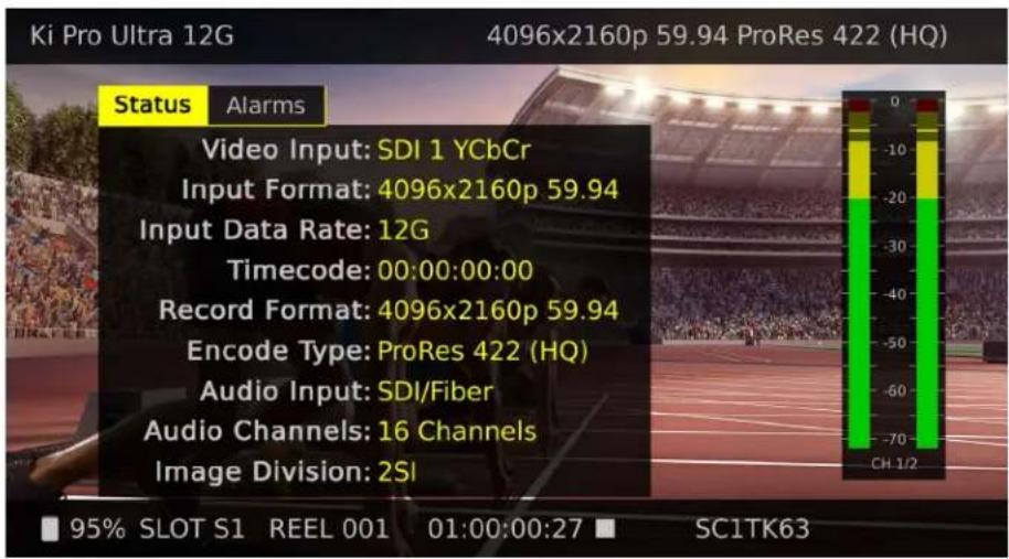
Status Display
In the Status menu, the User Control Knob will toggle between the two tabs: Status and Alarms. These are Read-Only displays.
The Status page shows the status of recording or playing including:
- Input type and format
- Timecode settings for recording (set in Config parameter 8.0)
- Recording Format and Encoding type
• Audio Input and number of Channels
The following figure shows an example display for the Status menu. Note that the Display button has been pressed twice to include the VU meters.
Figure 8. Status Overlay Display
text_image
Ki Pro Ultra 12G 4096x2160p 59.94 ProRes 422 (HQ) Status Alarms Video Input: SDI 1 YCbCr Input Format: 4096x2160p 59.94 Input Data Rate: 12G Timecode: 00:00:00:00 Record Format: 4096x2160p 59.94 Encode Type: ProRes 422 (HQ) Audio Input: SDI/Fiber Audio Channels: 16 Channels Image Division: 2SI 95% SLOT S1 REEL 001 01:00:00:27 SC1TK63Config and Media Displays
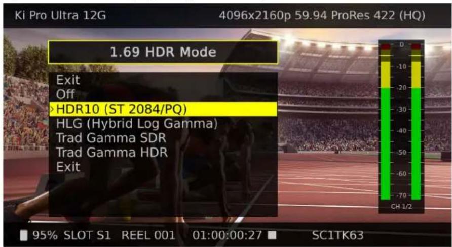
In the Config and Media menus, the User Control Knob scrolls through various adjustable parameters, and pressing the knob activates menu field for scrolling through the choices (yellow outline indicates the field is active). When entering a menu, the system remembers and returns to the last selected parameter. The following figure shows an example of a display of a Config menu. Media menus are similarly organized.
Figure 9. Front Panel Display Config Menu Example
text_image
Ki Pro Ultra 12G 4096x2160p 59.94 ProRes 422 (HQ) 1.69 HDR Mode Exit Off HDR10 (ST 2084/PQ) HLG (Hybrid Log Gamma) Trad Gamma SDR Trad Gamma HDR Exit 95% SLOT S1 REEL 001 01:00:00:27 SC1TK63Audio Meters
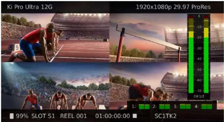
A large audio VU meter is available to display the level for the Ki Pro Ultra 12G's headphone audio. This meter can be shown or hidden by pressing the front panel Display button. You can select which audio channel pair to display, from the up to 16 channels supported, which is indicated by the CH numbers shown below the meter.
In Multi Channel mode you can also display smaller audio meters for the first two channels of each recording channel, by pressing the front panel Display button.
Figure 10. Audio Meters Front Panel Display Example
text_image
Ki Pro Ultra 12G 1920x1080p 29.97 ProRes 99% SLOT S1 REEL 001 01:00:00:00 SC1TK2Transport Mode (default)
Transport mode is the default mode for Ki Pro Ultra 12G. Transport functions are always functional except during some basic configuration operations as noted below. When you power up Ki Pro Ultra 12G, the first level overlay display will provide information for any clip that previously was recorded and it can be played.
The display shows settings you've made in the Media menus. You'll always know you are in Transport mode when the MENU buttons (STATUS, CONFIG, or MEDIA) are not highlighted — if one is highlighted, then you are in that menu.
When in the Idle mode (not playing or recording), you can access the Config and Media set-up menus to adjust various parameters that determine Ki Pro Ultra 12G operation.
Note that you must be in STOP, not PAUSE (Stop button flashing) to access these menus—if you try to access these menus without first having stopped playback, a "PRESS STOP" prompt will appear on the LCD display.
There are certain times when transport controls are locked out. For example, when ejecting media, or entering an IP address, the transport controls are locked out until the operation is completed. Most other menu functions do not lock out the transport controls.
At any time you only need to hit any transport button to exit (or "exit" a Status, Config, or Media menu by pushing its button). Pressing a transport button sends the display into the Transport default menu.
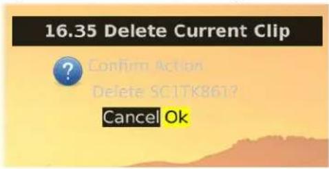
To protect from inadvertent actions, several operations (for example, Format Media) may result in a "CONFIRM ACTION" display. This ensures that accidental button presses don't cause problems. When you answer OK to a prompt, the display then changes to an "in progress display", and automatically returns to the menu when the operation is complete.
Figure 11. Confirm Action Dialog
text_image
16.35 Delete Current Clip ? Confirm Action Delete SC1TK861? Cancel OkCertain parameters are stored in non-volatile memory so that the parameter is remembered between power cycles, for example: system name and date/time.
Automatic 12G Signal Detection and Configuration
When set for a Single Encode Channel (Single Channel Mode) and the Ki Pro Ultra 12G is receiving a 12G signal on the SDI 1 or Fiber 1 input, the unit automatically configures itself to record and playback 6G and 12G signals.
Recording a Clip
There is more than one way to record a clip since you can control Ki Pro Ultra 12G in various ways. Here is an example of just how simple a recording can be:
- Press the STATUS button. You'll see the currently selected input and input format and the chosen recording format and audio input.
- If these settings are acceptable, then push the red RECORD button below the display.
- The green LED slot indicator (and the green LED on the Pak Media) will begin blinking indicating a recording is in progress. You will also see the timecode changing on the UI display.
- When you've finished recording, press the STOP button.
You can, of course, customize your configuration via the Config and Media menu parameters.
To change the Encoder Type (Apple ProRes, DNxHD) prior to recording, Press MEDIA, and then using the Control Knob, scroll until you see 14.1 Encode Type. Then press the knob to enter the menu. Scroll to the desired setting and press the knob again to select it, and press MEDIA or STOP to exit the menu.
IMPORTANT: To insure successful recording with the Ki Pro Ultra 12G it is good practice to use new, high-quality media that has been freshly formatted in the device. For best results, use qualified, AJA Pak Media only.
To select a different video input, press CONFIG, then scroll with the User Control Knob to 2.1 Video Input—then press the knob and scroll to a desired video input connector and press the knob to select. To select a different audio input, use the knob to access 2.2 Audio Input. Repeat the selection procedure to chose a desired audio input connector.
Ki Protect Recording Integrity
The Ki Protect feature helps to ensure ProRes data integrity if a media drive is accidentally removed or loses power during recording. If a recording is interrupted, the only data loss should be the last few frames that were in transit to the media drive to be recorded. Frames that are already recorded will be preserved and are recoverable.
Recording Notes
Ki Pro Ultra 12G alerts you when the media is nearly full with a "Media Low" prompt at 15% of the remaining capacity. At 10% of the total capacity of the media, the "Media Full" prompt will appear. Any recordings that have been started will stop once 10% is reached and no further recordings can be performed using this media until it is formatted again or a MEDIA>Delete Clips>DELETE ALL has been performed. Deleting clips to produce more than 10% free space will allow recording to resume.
Rollover Recording
Ki Pro Ultra 12G lets you record long duration material on two Pak Media drives, with automatic or manually initiated rollover across the drives. Set the Media Menu 12.2 Rollover parameter to ON, insert two Pak Media modules, ensuring the second one is formatted but empty, and initiate your recording. When the first Pak Media reaches 90% capacity, recording will automatically continue onto the next drive with no lost frames.
To force a change over before the first drive is filled during a rollover recording, simply press and hold the Ki Pro Ultra 12G front panel SLOT button for two seconds.
NOTE: Initiating rollover through the Ki Pro Ultra 12G web UI is not supported.
Infinite Record
The Infinite Record feature lets you use Ki Pro Ultra 12G as an always running backup recorder. When operating in this mode, clips are recorded to Pak Media in one slot, and when that media capacity is near filled, Ki Pro Ultra 12G automatically formats the other slot's Pak Media and switches the recording over to it, alternating back and forth indefinitely.
CAUTION: During Infinite Record, Ki Pro Ultra 12G automatically formats the next Pak Media to be used, so data loss will occur without user intervention.
Recording Multiple Clips
Ki Pro Ultra 12G can record up to four HD clips simultaneously, after it has been set to Multi Channel Mode.
IMPORTANT: The Ki Pro Ultra 12G recording inputs must be genlocked together, or multi-channel recording and monitoring failures may occur.
IMPORTANT: Multi-channel recording is only supported on Pak 2000 and Pak 1000 media, and on R1 and later versions of Pak 512 Pak 256 media.
-
Press the CONFIG button if necessary to display the configuration menus.
-
Go to menu 1.10 and select Multi Channel. The front panel display will go blank momentarily, and then the unit will return to operation in Multi Channel Mode.
-
Go to 1.11 Channels To Record and select 2, 3 or 4 channels. The numbered SDI input connectors are mapped 1 to 1 to the numbered record channels.
- You can set different encoding for each channel by pressing the MEDIA button, going to menus 14.2, 14.3, or 14.4 Channel Encode Type and selecting the encoding for that channel.
- You can now push the red RECORD button below the display to initiate recording on all the channels.
- When you've finished recording, press the STOP button.
Multiple recorded clips have "_n" appended to their clip names, with "n" being the 1-4 number of that recording.
Playing Back a Clip
To playback recorded media, select a clip and press PLAY. If the clip you wish to playback is not currently selected, use the User Control Knob to scroll until the clip name appears on the bottom right of the display. Like recording, there is more than one way to initiate playback (front panel or web browser). From the front panel these are the basic steps:
- Press the STOP button to get to the Transport mode (if not already there). Find the clip name in the display (it shows the current Slot, Reel, and Clip name).
- Turn the User Control Knob until you find the clip you are looking for.
- Press the PLAY (>) button.
- When playing back a clip (PLAY, FFWD, or REV) the first push of STOP acts as a "Pause" mode: the playback is paused, the current point of the clip is displayed, and the STOP button will flash. A second push of STOP will completely stop the playback and Ki Pro Ultra 12G outputs will go into an "idle" mode (the currently selected inputs are passed to the outputs). When a playback reaches the end of a clip, it will automatically pause on the last frame of the clip.
Transport Buttons
During playback you can use the FFWD, REV, SELECT, or User Control Knob as follows:
FFWD >>
Press button to begin fast playback of the current clip at 2x speed. Successive pushes increase the speed to 4x, 8x, and 16x. (Pushing the button after 16x speed is reached has no further effect.) When fast-forwarding, audio is muted.
REV <<
Pressing REV when not highlighted, begins playback of the current clip in reverse at 1x speed. Successive pushes increase the speed to 2x, 4x, 8x, and 16x. (Pushing the button after 16x speed is reached has no further effect.) When playing in reverse, audio is muted for all speeds.
User Control Knob
While in Transport mode, the User Control Knob will scroll through the clips in the active media. When a clip is selected it is "cued" to the beginning of the clip. Note that ordering and playback of clips is based on timestamp order, not clip name.
JOG Mode
While in Transport mode, pressing in the Control Knob toggles to Jog mode. (JOG is displayed in the overlay display). In this mode, turning the Control Knob will "single step" the current clip one frame forward or backward per scroll-click.
Deleting Clips
To delete a previously recorded clip:
- In Transport mode, use the User Control Knob to browse through the clips on the current media. When a clip is on another media you will press SLOT until it's selected.
- When you find a clip you want to delete, press the Media button, scroll to 16.25 to delete the current clip and press the knob.
- Ki Pro Ultra 12G asks, "CONFIRM ACTION." Choose OK and press the User Control Knob to confirm deletion. Pressing any other button, will abort the deletion.
NOTE: When deleting large clips, Ki Pro Ultra 12G will display a progress status window on the front panel and the WEB UI. Large clips can take up to 30 seconds to delete. To remove all clips on a drive, it is faster to format the drive.
Status Menus
The Status menus display I/O status and Alarm information. The Status menu can be accessed almost anytime and will not change any active transport modes. Use the User Control Knob to toggle between the tabs for Status display and ALARMS display. Press the STATUS button or any transport button to return to Transport mode, where an action could still be occurring (like playback or even recording).
Record Mode
As mentioned earlier in this chapter transport display provides the following:
Top Line
Displays the current clip Format information.
Bottom Line
Displays:
• Percentage of media capacity available
- Current media Slot number
- Current reel number
- Timecode for the clip being recorded or played
- Current clip name
- If closed captioning is present [CC]
Alarm Status
The Alarm menu displays warnings and alarms. Some alarms will automatically be shown on the top bar of the display. Others will be indicated by the STATUS button flashing.
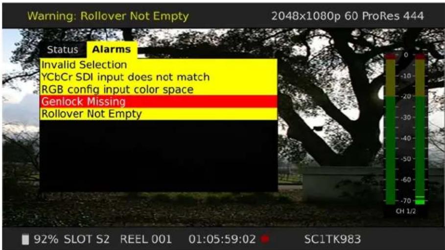
Examples of ALARM displays are shown below.
Figure 12. Warning Examples
text_image
Warning: Rollover Not Empty 2048x1080p 60 ProRes 444 Status Alarms Invalid Selection YCbCr SDI input does not match RGB config input color space Genlock Missing Rollover Not Empty 92% SLOT S2 REEL 001 01:05:59:02 SC1TK983Once there is a Ki Pro Ultra 12G alarm active, the STATUS button light will blink for as long as the alarm is present. This alerts you so you'll know the reasons for the alarm condition are still active—you can then check the ALARMS display by pressing the STATUS button and using the User Control Knob to scroll to the ALARMS tab.
If you enter the Config or Media menus after an alarm notification, the alarm display will go away. Pushing any button always returns Ki Pro Ultra 12G to its pre-alarm state—however, if you are unable to correct the alarm condition after this initial button push, when you leave these menus, the alarm notification will reappear on the display.
Ki Pro Ultra 12G features a variety of alarms to help you diagnose the condition of the unit, possible configuration issues, or possible signal issues.
Warning: Input Format Changed- This prompt appears if a recording is started and the signal is lost or changed. If this occurs, Ki Pro Ultra 12G stops the recording that is in progress (unless the Loss of Video Config menu parameter is set to continue recording.)
Warning: No Video Input - May appear if there is no video input to Ki Pro Ultra 12G. No recording will be performed in this state.
Warning: Input Error - May appear if a format or frame rate that is not supported is supplied to the Ki Pro Ultra 12G or a link of a multi-link signal (dual link or quad link) is missing; no recordings will be produced if this alarm appears.
Warning: Dropped Frames - May appear if media is under-performing and cannot keep up with the data rate required to make a recording or perform a playback. If you see this prompt during recording, recordings will stop. If this prompt appears, you might consider backing up your current recordings and formatting the media. For playback, you might simply re-attempt playback.
Warning: Media Low - Appears when the media only has 15% of capacity remaining. Media must be switched out when it reaches 10% of capacity. With 10% of media remaining, the "Warning: Media Full" prompt will appear.
Warning: Media in Use - May appear if you try to use media while another operation is still taking place. Wait for the operation to finish and then try again or press STOP.
Warning: Media Not Present - May appear if media has been physically removed and the user hits the slot button.
Warning: Media Unformatted - May appear if Ki Pro Ultra 12G does not recognize the file system on the SSD media or the media has never been formatted.
Warning: Storage Removed - Appears if the media is removed without first hitting the SLOT button to properly unmount it. In the event this happens, media immediately re-inserted into the Ki Pro Ultra 12G may show clips as "N/A" and subsequent recordings may not be possible. To resolve this issue, mount the media on an Apple computer under macOS, then remove and re-insert the media into your Ki Pro Ultra 12G. If the media does not read properly, you will need to format it. Additionally, this alarm will lead to the "Please Reboot" prompt.
Warning: Please Reboot - Appears if media was removed without the use of the slot button and the Ki Pro cannot continue operating and must be rebooted.
Warning: Backup and Reformat - May appear if the media has issues being mounted by the Ki Pro Ultra 12G. As the prompt indicates, it is best to back up the media by copying it to another hard drive or disk array and then reformat the media. Some signs that the media is in a read-only state: even though clips have been recorded to the media, "N/A" appears in the clip area of the UI, "Loading" appears in the clip area of the UI but does not eventually load a clip, or hitting the record button with all settings correctly configured for the Ki Pro Ultra 12G does not result in a recording.
Warning: Rollover Not Empty - Appears if media for a rollover is not empty and contains existing recordings; the rollover feature requires empty media to operate.
Warning: Rollover Media Unformatted - Appears if media for a rollover is not formatted or recognized.
Warning: Name in Use - Appears if the clip name specified in the naming parameters already exists on the media; this happens when take 999 is reached and no more take numbers are available. Ki Pro Ultra 12G will refuse to overwrite the clip; you will have to delete the clip or select a new name.
Warning: No Clip Name - Appears if you attempt to record in gang mode using a non-existent custom clip name.
Warning: Genlock Missing - Appears if you choose "Input" or "Ref In" for 6.1 Genlock and you attempt to play a clip and no genlock is detected on the selected input.
Warning: 2 Channel Format - Appears if the number of channels selected in 2.3 Audio Channels is eight, but the selected audio input only supports two channels.
Warning: Invalid Selection - May appear if unsupported menu selections are made for video input, record type, encode type, captions (not available for MXF) etc.
Warning: Media does not support A/V format - This appears when the media cannot reliably sustain the configured video format, frame rate and number of audio channels currently configured (perhaps due to legacy Pak Media).
Warning: Rollover media does not support A/V format - Same as above but for the current rollover media (perhaps due to legacy Pak Media)..
IMPORTANT: After rollover media has been inserted and scanned, if A/V settings are subsequently changed to values that are not supported, Ki Pro Ultra 12G may not identify the misconfiguration until the time of rollover, at which time the recording will stop.
Warning: Interval Record Enabled - This alarm informs the user that the Interval Record feature is enabled.
Warning: Invalid Multi Channel Record Format - Some combinations of video format, frame rate, encode type and number of audio channels are not supported in Multi Channel Mode. 2K formats are prohibited and 444, 422HQ and 422 encodings have restrictions. The alarm detail describes the settings that triggered the alarm.
Warning: Record Inhibited - Appears if combinations of video format, frame rate, encode type and number or audio channels are not supported and result in a "Record Inhibited" alarm. This warning usually becomes an Error when the record button is pressed (the system refuses to start recording).
Warning : Infinite Record Enabled - Infinite Record will format second drive prior to rolling over.
Media Menus
The Media menu parameters affect media storage and the type of encoding to be used. Menus are also available for naming reels, clips and takes.
Media Menu Parameters
12.1 Media State
This parameter applies to using the Ki Pro Ultra 12G to transfer data.
| Record-Play (default)Data-LAN | Use media to record and play video.LAN data may be uploaded/downloaded to/from Ki Pro Ultra 12G. |
For normal video operation, select Record-Play. For data transfer using an Ethernet LAN, choose Data-LAN. The Data Media State allows valid media to be copied to or from the Ki Pro Ultra 12G.
Valid Transfer Files
Valid media files must have Ki Pro Ultra 12G. supported video formats and frame rates, be full raster, and must use 24-bit 48kHz audio, if audio is included. Files copied to Ki Pro Ultra 12G that do not meet these criteria may not appear in the web UI or front panel UI when you review clips.
Ki Pro Ultra 12G files are only transferred to and from the "AJA" folder on Pak Media. Files located elsewhere on that Pak Media, even if they are valid, will not appear in the Ki Pro Ultra 12G web UI or front panel UI.
Media State Modal Operation
If the state is designated as Data, the Transport functions are locked; in other words, media cannot be recorded or played back as video. You can still access Media menu parameters, however, so you can reset the parameter. If the you attempt to playback or record while in the Data mode, a "CHANGE MEDIA STATE" prompt alerts you that you cannot use the transport functions. Additionally, the front panel UI states that the unit is in a "DATA MEDIA STATE" in an obvious way as opposed to presenting the typical clip, reel, timecode, etc. usually seen on the front panel.
After you select the Data state, you can connect the Ki Pro Ultra 12G to a host computer via the Ethernet connection. The Ki Pro Ultra 12G will allow access to the selected media designated by the highlighted LED. In other words, if the #2 media module is selected on the Ki Pro Ultra 12G, that would be the volume mounted by the host computer operating system.
The DATA MEDIA STATE does not survive reboots or power cycles of the device. After such an event, it returns to the default Record-Play mode.
IMPORTANT: When the Ki Pro Ultra 12G is in the Media State and the Data - LAN selection is used, only the web UI for control and configuration of the Ki Pro Ultra 12G may be used for data transfer. The web UI will present "Upload+" and "Download+" buttons in the All Clips portion of the UI. If the Data-LAN state is not active, these buttons do not appear in the web UI.
122 Rollover
This parameter determines whether the Ki Pro Ultra 12G is configured to support recordings that continue when the selected Pak Media becomes full.
| OFF (default)ON | The Ki Pro Ultra 12G performs recordings normally and do not continue onto additional media.When a Ki Pro Ultra 12G recording reaches the 10% of capacity “Media Full” point, “appended” files on additional Pak Media are created for rollover recording. |
NOTE: Rollover recording is automatically enabled when the Ki Pro Ultra 12G Infinite Record feature is initiated.
Example
A recording is begun on the first piece of Pak Media, S1, and is called "SC1ATK1". When this piece of Pak Media reaches capacity, the second piece of Pak Media (S2) is seamlessly engaged and begins an appended recording, "SC1ATK1+1". This can continue until this piece of media reaches capacity.
IMPORTANT: If a piece of media is inserted for a rollover and it does not meet the following criteria, rollover recordings will not be possible:
- The rollover media needs to have already been formatted in the Ki Pro Ultra 12G
- The rollover media needs to be completely empty; no clips can already be on the media
If the Rollover parameter is set to ON and rollover media does not meet the criteria noted, warning alarms may appear such as:
• Warning: Media Unformatted
• Warning: Rollover Media Not Empty
NOTE: Pressing the Ki Pro Ultra 12G front panel SLOT button during a rollover recording forces a change-over to the other Pak Media.
123 Record Minutes (max)
This parameter specifies the maximum record length of clips. The range is 5 minutes to 240 minutes (4 hrs).
When the max clip time is reached Ki Pro Ultra 12G automatically continues to record and creates a new clip. The clip naming convention is the same as Rollover record (appending +n to the file name). During playback, Ki Pro Ultra 12G will play the clips as if they are one continuous recording. When these clips are imported into a NLE, they can be seamlessly combined into a single clip without audio or video drop out.
| 5 to 240 (default = 240) | Press Control Knob and scroll up or down to change the Record Minutes (max) value. |
12.6 Infinite Record
Ki Pro Ultra 12G can operate as an always running backup recorder.
NOTE: When Infinite Record is initiated, the Ki Pro Ultra 12G Rollover recording feature is automatically enabled
When Infinite Record is ON, Ki Pro Ultra 12G will continuously record to its first Pak Media. When that media approaches its capacity (15% remaining), Ki Pro Ultra 12G automatically formats and erases its second Pak Media. When the first Pak Media reaches 10% remaining, Ki Pro Ultra 12G automatically switches the recording over to the second Pak Media. When that second Pak Media reaches 15% capacity, Ki Pro Ultra 12G formats the first Pak Media, and at 10% remaining capacity switches recording back to it. Alternatively recording back and forth between the Pak Media allows indefinitely long recordings, and at least 85% of the material recorded onto one Pak Media drive will always be available for use.
CAUTION: During Infinite Record, Ki Pro Ultra 12G automatically formats the next Pak Media to be used, so data loss will occur without user intervention. To prevent loss of data, remove filled Pak Media from its slot (when the green light is off), and replace it with another Pak Media that can be safely formatted.
| OFF (default)ON | No Infinite Recording occurs.Recordings will automatically alternate between the two slots indefinitely. |
14.1 Encode Type
(Single Channel Mode only) This parameter defines the encoding method to be used for recording.
| ProRes 444 (XQ) | Record media as Apple ProRes 444 XQ files. |
| ProRes 444 (default) | Record media as Apple ProRes 444 files. |
| ProRes 422 HQ | Record media as Apple ProRes 422 HQ files. |
| ProRes 422 | Record media as Apple ProRes 422 files. |
| ProRes 422 LT | Record media as Apple ProRes 422 LT files. |
| ProRes 422 PX | Record media as Apple ProRes 422 PX files. |
| DNxHD HQX (220x) | Record media as Avid DNxHD HQX (220x) files. |
| DNxHD SQ (145) | Record media as Avid DNxHD SQ (145) files. |
| DNxHD LB (36) | Record media as Avid DNxHD LB (36) files. |
| DNxHR HQX | Record media as Avid DNxHR HQX files. |
| DNxHR SQ | Record media as Avid DNxHR SQ files. |
| DNxHR LB | Record media as Avid DNxHR LB files |
14.2 Channel 1 Encode Type
(Multi Channel Mode only.) This parameter defines the Apple ProRes encoding method to be used for channel 1.
| ProRes 444 (default) | Record media as Apple ProRes 444 files. |
| ProRes 422 HQ | Record media as Apple ProRes 422 HQ files. |
| ProRes 422 | Record media as Apple ProRes 422 files. |
| ProRes 422 LT | Record media as Apple ProRes 422 LT files. |
| ProRes 422 PX | Record media as Apple ProRes 422 PX files. |
14.3-14.5 Channel 2-4 Encode Type
(Multi Channel Mode only.) This parameter defines the Apple ProRes encoding method to be used for channels 2, 3, and 4 (see above).
14.6 File Format
(Single Channel Mode only) This parameter defines the encoding file format. The MXF format becomes available when a DNx encode type is selected above.
| MOVMXF | Record media as MOV.Record media as MXF. |
NOTE: DNxHR is only supported with MXF file types.
15.1 Play Media
This parameter determines behavior during playback.
| One (default)AllPlaylist | Plays one clip and then stops playbackAll/Playlist—Plays the current clip and then continues playing the next clip on the Ki Pro Ultra 12G media or the playlist. Note that with this setting, Ki Pro Ultra 12G will play all clips back regardless of format or frame rate—but you may notice the video monitor reset for format/frame rate changes. If all clips are the same format and frame rate or conversion is applied to the output for clips with the same Hz, then clips play out smoothly one after another. |
152 Loop Play
This parameter turns looped playback on and off.
| OFF (default)ON | Play clip(s) and then stop playback when completePlay clip(s) and then loop back and repeat playback |
15.3 Playlist
This parameter displays the name of the selected playlist.
| variable The name of the selected playlist appears. If no playlist is selected via the web UI controls, then no name appears. The user cannot select or create playlists from the front panel UI; these tasks are handled using the web UI. |
15.4 Dropped Frames
This parameter determines how playback handles dropped frames.
| CONTINUE STOP | In the unlikely event that the playback of a clip(s) begins to drop frames, this parameter allows users to define whether the playback continues or stops. |
16.0 File System Formatting
This parameter is used to select the type of file system for formatting the media.
| HFS+ (default)ExFAT | Select HFS+ formatting (macOS only)Select ExFAT (PC or macOS) |
16.2 Format Media
This parameter is used to format the currently selected media using the file system type selected in the previous menu.
| CANCEL (default)Format Media | No action (do not format the media selected)Format the selected media: press Control Knob and CONFIRM ACTION to Format the media) |
16.3 Delete Clips
This parameter can be used to delete all of the clips in the AJA folder on the media.
| KEEP CLIPS (default)DELETE CLIPS | No action (do not delete clips)Press Control Knob and CONFIRM ACTION to Delete all clips on the storage device |
NOTE: Ki Pro Ultra 12G media can be used to hold any data file. If other files are saved to the media, placing them outside of the "AJA" folder will prevent them from being deleted if a MEDIA>Delete Clips>DELETE ALL is performed.
16.35 Delete Current Clip
This parameter can be used to delete the currently selected clip on the media (see the bottom display for clip name).
| KEEP CLIPS (default)DELETE SELECTED CLIP | No action (do not delete the selected clip)Press Control Knob and CONFIRM ACTION to Delete this clip from the storage device |
17.0 Preset Reel Name
This parameter determines the reel name associated with all clips generated while using this setting.
| 001 to 999 (default = 001) | Press Control Knob and scroll up or down to change the Reel Name value from 001 to 999. |
The reel name is a number between 001 and 999. It is historically linked to the naming conventions used for film and tape-based media. The Reel Name is an incrementing three digit value that works with EDLs. For this reason, the parameter does not have a "NONE" selection—all clips will be associated with a Reel Name. The Reel Name parameter determines the name that the media will have if it is formatted and will appear when the media is mounted on a computer.
17.1 Unit Designation
This parameter defines a letter designation for recordings when using the 17.7 Combined Name menu parameter.
- A to Z – Selects a value between A and Z
NOTE: The Unit name is not part of a clip name unless the 17.7 Combined Name menu parameter is enabled.
| SELECT A USER DESIGNATION LETTER | Press Control Knob and scroll to the desire alphabetic letter (A – Z) your unit designation. Press the knob again to select. |
17.2 Clip Name
This parameter determines the clip name associated with all clips generated while using this setting. The clip name is either "Clip" or "SC".
| SC (default) Clip | Clips generated will have filenames beginning with “SC” Clips generated will have filenames beginning with “Clip” |
NOTE: In Multi Channel Mode, multiple clips have "_n" appended to their names, with "n" being the 1-4 channel number of that clip.
Clip Naming—Two Examples
The following two examples show how clip names are generated. Each example is based on the collective settings for these parameters:
- Reel Name
- Clip Name
- Clip Number
- Clip Number Append
- Alpha Append Value
In both examples that follow, "TK" is a default append to the naming convention just prior to the auto-incrementing TK value (which can be manually overridden via parameter 17.8 Take).
Example 1
Using the factory default AJA parameter settings:
| Reel Name 001 | |
| Clip Name SC | |
| Clip Number 1 | |
| Clip Append Alpha | |
| Alpha Append A | |
| Take 1 |
The resulting clip would be named and displayed as: "SC1ATK1". The media would be named "001" if mounted on the OS X desktop as a volume.
Example 2
Using customized settings:
| Reel Name 002 | |
| Clip Name Clip | |
| Clip Number 12 | |
| Clip Append NONE | |
| Alpha Append B | |
| Take 1 |
The resulting clip would have the following naming convention: "Clip12TK1". The media would be named "002" if mounted on a desktop as a volume.
173 Clip Number
This parameter determines the clip number, from 1 to 999, that follows the Clip Name, and is associated with all clips generated while using this setting.
| 1 to 999 (default = 1) | Press Control Knob and scroll up or down to change the Clip Number value from 1 to 999. |
174 Clip Append
This parameter is used with parameter 17.5 Alpha Append to append a text value after the Clip Number or have no text appended.
| Alpha (default)NONE | The text value entered in Alpha Append is appended to the Clip Name and Clip NumberNo text is appended to the Clip Name and Clip Number |
175 Alpha Append
This parameter is present when parameter 17.4 Clip Append is used to append a text value after the Clip Number.
| A to Z (default = A) | Press Control Knob and scroll up or down to change the Alpha Append value from A to Z. Alphabetic values increment with A and Z wrapping around. |
17.6 Take
This parameter determines the Take number, from 1 to 999, that follows the Clip Name and Clip Number, followed by any Alpha Append (if selected), generated for all clips while using this setting.
| 1 to 999 (default = 1) | Ki Pro Ultra 12G automatically generates a Take number. Press Control Knob and scroll up or down to change the Take value from 1 to 999, if you want a value other than the automatically generated value. |
Ki Pro Ultra 12G follows these Clip and Take rules when using standard naming conventions:
- Ki Pro Ultra 12G will not overwrite an existing clip.
- The Take number will auto-increment past existing numbers for the "prefix" as defined by the Reel Name, Clip Name, Clip Number, Clip Append, Alpha Append, and Take settings.
- If the number is at "999", Ki Pro Ultra 12G will record a clip with take 999, but then cannot auto advance so the second attempt to record will generate a "Name In Use" alarm. This prompts you to select a new Clip Name, Clip Number, Clip Append, Alpha Append, and/or Take settings so that a new unique "prefix" is created. This action ensures files are unique and understandable, and that clips are never overwritten.
17.7 Combined Name
This parameter combines the Unit Designation, the Reel Name, Clip Name, Clip Number, Clip Append, Alpha Append and Take into a single file name.
| OFF (default)ON | The combined clip name is not enabled.The combined clip name is enabled |
Example: A001SC1ATK1
Custom Clip Naming
Users can elect to give their clips names other than the standard criteria provided by AJA.
IMPORTANT: Certain characters may not be allowed or supported if entered for a clip name. Examples include: punctuation marks (other than internal spaces or periods), special characters (like @ and _), and non-ASCII UTF-8 characters are rejected outright. Non-UTF-8 characters appear in some languages, like Chinese and Japanese are not supported.
Custom clip names can be created via the front panel UI menu parameters (19.1, 19.2, and 19.4) with the User Control Knob. Users may find that the more efficient method to perform custom clip naming is via the web UI entry fields.
NOTE: In Multi Channel Mode, by default multiple clips have "_n" appended to their names, with "n" being the 1-4 channel number of that clip. You can use 19.5 Channel Clip Identifiers add a name to each channel as you wish.
19.1 Use Custom Clip Name
This parameter enables or disables whether a custom clip name can be used via menu parameters 19.1, 19.2, and 19.4, or via the web UI.
| OFF (default)ON | Enable defining of custom clip nameDisable defining of custom clip name |
192 Custom Clip Name
This parameter defines a custom clip name. The custom name is defined via the front panel User Control Knob or the web UI. The default is "CUSTOM".
| variable When entering characters for a custom clip name on the front panel, you must press the User Control Knob to bring up alpha-numeric keypad. Use the Control Knob to scroll and press to select the characters you want. Save or Cancel when finished.Default: CUSTOM |
19.4 Custom Take
This parameter defines a custom take. The custom take number is defined via the front panel User Control Knob.
| 1 to 999 (default = 1) | Press the Control Knob and scroll to change the Take value from 1 to 999, if a value other than the automatically generated value is desired. |
195 Use Channel Clip Identifiers
(Multi Channel Mode only.) This parameter activates appending a channel identifier to the file name.
| OFF (default)ON | Channel clip identifier not added.Channel clip identifier is appended to the file name. |
This feature is useful if you wish to use a camera position instead of the default channel number. For example:
Use Channel Clip Identifier OFF, Use Custom Clip Name OFF
- SC1TK1_1.mov
- SC1TK1_2.mov
- SC1TK1_3.mov
- SC1TK1_4.mov
Use Channel Clip Identifier ON, Use Custom Clip Name OFF
• SC1TK1_1-presenter-camera.mov
• SC1TK1_2-guest-camera.mov
• SC1TK1_3-audience-camera.mov
• SC1TK1_4-backstage-camera.mov
Use Channel Clip Identifier ON, Use Custom Clip Name ON
- GuestInterview_1_1-presenter-camera.mov
- GuestInterview_1_2-guest-camera.mov
• GuestInterview_1_3-audience-camera.mov
• GuestInterview_1_4-backstage-camera.mov
19.6-19.9 Ch 1-4 Clip Identifier
(Multi Channel Mode only.) This parameter lets you edit the channel clip identifier text. Clip identifier text is defined via the front panel User Control Knob or the web UI.
| variable When entering characters for a custom clip identifier on the front panel, you must press the User Control Knob to bring up alphanumeric keypad. Use the Control Knob to scroll and press to select the characters you want. Save or Cancel when finished. Default: Ch.1-4, depending on record channel. |
22.1 Gang Clip Name
This parameter is used when performing gang recording via multiple Ki Pros (refer to Controlling Multiple Ki Pros later in this manual). If the desire is to have clips named the same across all Ki Pro ganged units' recordings, then use the "Master Name" selection in this parameter. If the desire is to have clips named independently on Ki Pro units, then "Subordinate Name" should be selected. Selecting "Subordinate Name" means that the recording will take its name from the individual Ki Pro's parameters and not accept the value pushed to the Subordinate by the Master Ki Pro.
| Master Name (default)Subordinate Name | Enable clips to be named the same across all Ki Pro ganged unitsName clips independently on Ki Pro units |
NOTE: Most gang controls are only available in the web user interface.
22.4 Captions
This parameter is used to capture of CEA-708 Closed Captioning data as QuickTime movie tracks.
On recording, Ki Pro Ultra 12G extracts CEA-708 (including 608 within 708) packets contained in the vertical ANC data embedded in the SDI input (BNC or Fiber) signal. The packets are processed and inserted into a QuickTime track (CLCP) as part of the recorded QuickTime container.
| Disabled (default) Enabled | No caption track will be created nor will any arriving captions be written to the clip.Writes any captioning data that arrives during the recording into a QuickTime track (CLCP). |
On playback, Ki Pro Ultra 12G will process the QuickTime container file, process the CLCP track if present and insert/embed closed captioning data on the main SDI outputs (BNC or Fiber) VANC. No user configuration is required for caption playback.
NOTE: Closed captioning is not supported on HDMI inputs/outputs or the SDI monitor output.
Config Menus
As in the Media menus already presented, pressing the User Control Knob and scrolling changes the current Config parameter's value to a new one from the Ki Pro Ultra 12G list of choices—repeating the list if you continue to scroll—or adjusting a numerical value up or down.
The exact choices displayed will vary depending on the parameter. Most adjustment choices made with the Control Knob take effect immediately and will be subsequently stored into the Ki Pro Ultra 12G non-volatile memory if they remain unchanged for 3 seconds.
The Config menu is for system set-up and configuration. Each parameter is numbered, in the same manner as the Media menus.
Config Menu Parameters
Many of the Config menu parameters are used together to configure the type of Ki Pro Ultra 12G recording and associated conversion formats used on the input or output for a particular workflow.
1.1 Record Type
This parameter defines the frame recording method. Record Type can be configured to record the incoming video signal in a "NORMAL" manner (a standard format) or "PsF" progressive format.
| NORMAL (default) | Record standard format as input |
| PsF | Record progressive segmented frame |
NOTE: A 23.98Hz source is automatically treated as PsF, regardless of this setting. For 29.97 Hz or 25 Hz, "NORMAL" means encode as interlaced and "PsF" means encode as progressive. This only applies to 1080 formats. The following details clarify each case:
- 1080PsF 23.98 incoming video > Normal selected > 1080p 23.98 recorded to disk.
- 1080i 25 incoming video > PsF selected > 1080p 25 recorded to disk.
- 1080i 29.97 incoming video > PsF selected > 1080p 29.97 recorded to disk.
- 1080PsF signal is recorded to disk as progressive; progressive material on disk may be played back as PsF or progressive on the video outputs; this selection can be made in parameter 1.3 Progressive Playback.
1.10 Encode Channels
This parameter determines whether a single clip will be recorded (Single Channel Mode), or multiple clips will be simultaneously recorded (Multi Channel Mode).
Single Channel (default) Multi Channel
Record one clip. 4K UltraHD is supported. Record up to four clips. HD only.
IMPORTANT: The Ki Pro Ultra 12G recording inputs must be genlocked together, or multi-channel recording and monitoring failures may occur.
1.11 Channels to Record
(Multi Channel Mode only.) This parameter determines the number of multiple clips (2-4) will be recorded in Multi Channel mode. The numbered SDI input connectors are mapped 1 to 1 to the numbered record channels.
NOTE: In Multi Channel Mode, multiple clips have "_n" appended to their names, with "n" being the 1-4 channel number of that clip.
2 channels 3 channels 4 channels (default)
Record two clips simultaneously. Record three clips simultaneously. Record four clips simultaneously.
1.15 SDI Monitor Channel
(Multi Channel Mode only.) Controls which channels are displayed by the SDI Monitor output.
Channel 1 Channel 2 Channel 3 Channel 4 All Channels (default)
Display only channel 1 (clip_1) Display only channel 2 (clip_2) Display only channel 3 (clip_3) Display only channel 4 (clip_4) Display all four channels in quadrants.
1.16 HDMI Monitor Channel
(Multi Channel Mode only.) Controls which channels are displayed by the HDMI output (see above).
1.3 Progressive Playback
This parameter defines the format applied when progressive media is played from storage.
Progressive (default) PsF
Playback as standard progressive frame Playback as progressive segmented frame (regardless of what was recorded when input)
NOTE: HDMI output of progressive material requires the use of 1080p Playback set to Progressive; HDMI only tends to support true progressive or interlace video, not PsF.
1.4 In Convert
(Single Channel Mode only.) This parameter sets input conversion to one of the available selections.
| None (default)4K Crop to UltraHD4K/UltraHD to 2K/1080 | The input is not convertedConverts and crops 4K input to UltraHDConverts 4K input to 2K or UltraHD input to HD |
Note that the 4K Crop to UltraHD selection and the 4K /UltraHD to 2K/1080 selections have no impact if 2K or 1080 video is input. By default, the Ki Pro Ultra 12G will output 2K on the SDI monitor and HDMI monitor outputs if the incoming signal is 4K (4096x2160) or 2K (2048x1080) and no "In Convert" is applied. Also by default, if the incoming signal is UltraHD (3840x2160) or HD 1920x1080P, the Ki Pro Ultra 12G outputs 1080 HD on the SDI and HDMI Monitor outputs.
Also, if the 4K Crop to UltraHD "In Convert" selection is used, the Ki Pro Ultra 12G will output 1080 HD on the SDI and HDMI Monitor outputs.
1.5 Out Convert
This parameter sets output conversion to one of the available selections.
| None (default) | The output is not converted |
| 2K Crop to 1080 | Converts and crops 2K output to 1080 HD |
| 4K Crop to UltraHD | Converts and crops 4K output to UltraHD |
NOTE: The 4K Crop to UltraHD selection has no impact if a 2K or 1080 video source is used. Also, the 2K Crop to 1080 has no impact if a UltraHD or 1080 video source is used.
The SDI Monitor output always decimates the frame size when the input source is either UltraHD or 4K. Additionally, the user may select the Monitor Output's Out Convert option, which will mirror the selection made in the Out Convert menu, 1.5. In other words, if the input format is 2K, the user can choose "2K Crop to 1080" option in menu 1.5 and the "Out Convert" option in menu 1.8 to yield a 1080 output for downstream monitors that cannot accept a 2K signal.
1.6 SDI Out
(Single Channel Mode only.) This parameter sets the SDI output format. These are the options:
| SDI 1 RGB | Enables 12G signal output operation, and sets SDI 1 to RGB |
| SDI 1 YCbCr (default) | Enables 12G signal output operation, and sets SDI 1 to YCbCr |
| SDI 1-2 RGB | Sets SDI 1-2 outputs to RGB (supports up to 2K 29.97fps) |
| SDI 1-2 YCbCr | Sets SDI 1-2 outputs to YCbCr (supports up to 2K 59.94fps) |
| SDI 1-4 RGB | Sets SDI 1-4 outputs to RGB (supports up to 4K 29.97fps) |
| SDI 1-4 YCbCr | Sets SDI 1-4 outputs to YCbCr (supports up to 4K 59.94fps) |
NOTE: If the output format is UltraHD or 4K and SDI 1 RGB or YCbCr is selected, the output will be configured for 6G or 12G depending on video format. In this case, SDI and Fiber Outputs 2-4 will be disabled.
NOTE: SDI 1 RGB and SDI 1 YCbCr high frame rates (in excess of 29.97fps) are supported by 3G-SDI. Be sure to connect the AJA Ki Pro Ultra 12G to a 3G-SDI capable device in these cases. If a 3G-SDI capable device is not available, RGB and high frame rate YCbCr may be output via SDI 1 and SDI 2 as "dual link" 1.485Gbps."
1.63 SDI Playback Bit Depth
(Single Channel Mode only.) This parameter sets the SDI video output playback bit depth.
| Auto10-bit | Automatically selects 10 or 12-bit video output.10-bit video is output. |
NOTE: Bit depth changes only during playback, not in idle mode.
1.64 3G SDI Level
This parameter allows the 3G SDI output to be configured for either Level A or Level B. While many 3G SDI devices will support both Level A and Level B, some devices may need a specific 3G SDI selection to operate as expected.
| Level B (default)Level A | For use with devices that accept or require Level B.For use with devices that accept or require Level A. |
1.65 Playback Image Division
This parameter is used to select between Square Division or Two Sample Interleave output format (4K and UltraHD signals only). Menu options are:
| Auto (default) Square 2SI | In Idle mode, follow the input signal image division format. In Playback mode, follow the input signal format configuration. Forces the output to use Square Division. Forces the output to use Two Sample Interleave. |
NOTE: For ProRes recorded files, there is no way to record image division format information (VPID data is not recorded).
NOTE: If Menu 1.6 "SDI Out" has one of the following SDI outputs selected, playback is automatically selected and the "Playback Image Division" parameter setting has no effect.
- SDI 1 RGB
• SDI 1 YCbCr
1.66 HDMI Out
(Single Channel Mode only.) This parameter determines whether cropped, scaled or full raster video will be output.
NOTE: Full Raster output disables the Super Out feature; superimposed timecode and transport state is not possible with a 4K or UltraHD HDMI output.
| Crop | If the raster is 4K the HDMI Out is cropped to UltraHD. If 2K the HDMI Out is cropped to 1080. Other rasters are unchanged. |
| Crop and Scaled | HDMI Out is cropped and scaled where applicable. If the raster is 2K/UltraHD/4K cropping and scaling is applied so the output is 1080. |
| Scaled (Default) | If the raster is 4K the HDMI Out is scaled to 2K. If the raster is UltraHD the HDMI Out is scaled to 1080. |
| Full Raster | No cropping or scaling is applied. The HDMI Out raster is 1:1 and may be 4K or UltraHD. |
Helpful HDMI configuration guidelines:
- Determine your video source format and frame rate.
- Decide whether you want a Full Raster or Scaled output.
- Determine whether your connected device can support 4096x2160 or 3840x2160.
- Remember that the Progressive Playback menu parameter needs to be configured for Progressive for HDMI output.
1.68 HDMI/EDID Override
This parameter determines whether the HDMI Output is auto-negotiated with the receiving device via EDID (extended display identification data) or via a specified output type.
These are the options:
- Auto (default) – The HDMI output is negotiated automatically with the receiving device via EDID
- 8-bit RGB – Configures the HDMI output for 8-bit RGB
• 4K 4:2:0 (High FR)
NOTE: Typically, you will want to simply leave the selection configured for Auto so that the negotiation between the devices is handled automatically.
About High Dynamic Range and Wide Color Gamut
High Dynamic Range (HDR) and Wide Color Gamut (WCG) are relatively new ways to present video programming that gives brighter highlights, more detailed shadows, and additional colors with smoother gradients and increased saturation. HDR and WCG are display oriented features, dependent on the capabilities of the device presenting the video material.
When HDR Mode is On, the selected HDR metadata is added to the Ki Pro Ultra 12G's ProRes recordings, overwriting any HDR metadata that may already be present on the incoming signal.
The HDR related settings do NOT affect the output signals on the Ki Pro Ultra 12G's SDI BNC connectors (including Monitor BNC). No info frame data is included on any of those BNC outputs.
HDR parameter settings do not change any actual video image data. These settings are only used to add HDR identifying information (metadata) to the signal. HDR capable HDMI displays use this information to identify and properly process the signal to match the display's capabilities, optimizing the HDR video shown on that specific HDMI device. The HDR information is placed in an HDMI Dynamic Range and Mastering Infoframe and contains the static metadata descriptors as defined in CTA-861.3 and HDMI v2.0a.
NOTE: The built-in Ki Pro Ultra 12G front panel monitor supports Standard Dynamic Range. HDR menu settings or incoming HDMI metadata will not change the Ki Pro Ultra 12G's built-in monitor display characteristics.
To successfully use the Ki Pro Ultra 12G HDR menus you will need to know the HDR information associated with that specific video material:
- HDR Mode
- Color Gamut
• Mastering Display information - Program Luminance Levels
You then select the HDR operating mode and adjust the associated HDR menu parameters to match the information to be included in the HDMI output signal.
1.69 HDR Mode
The HDR Mode menu is used to indicate a High Dynamic Range (HDR) mode and gamma curve.
| Off (default)HDR-10 (SD 2084/PQ)HLG (Hybrid Log Gamma)Trad Gamma SDRTrad Gamma HDR | High Dynamic Range output mode is disabled.HDR-10 mode is indicated.HLG mode is indicated.HDR is indicated with an SDR gamma curve (BT. 709).HDR is indicated with an HDR gamma curve (BT. 2020. |
NOTE: When enabled, the associated HDR menus listed below become available.
1.70 HDR Color Gamut and White Point
Identifies the video color gamut and white point. Color gamut defines the locations for the three vertices of the color primaries, as well as the white point within the x-y plane of the CIE 1931 color space and, for HDR, the SMPTE ST 2086 color volume.
| DCI-P3 D65 (default)BT.2020 | Presets a DCI-P3 cinema color gamut and D65 white point.Presets an ITU BT.2020 color gamut and white point. |
1.71 HDR Mastering Luminance Min
Identifies the minimum luminance of the mastering display used on the video material.
- Use the slider to select from 0 to 0.4000 cd/m2 (default 0.0050 nits).
1.72 HDR Mastering Luminance Max
Identifies the maximum luminance of the mastering display used on the video material.
- Use the slider to select from 0 to 4000 cd/m2 (default 1000 nits).
1.73 HDR Content Light Level Max
Identifies the highest luminance level encountered anywhere in the video material.
- Use the slider to select from 0 to 4000 cd/m2 (default 1000 nits).
1.74 Frame Average Light Level Max
Identifies the average of the luminance levels of all the frames of the video material, similar to the HDR Content Light Level Max described above.
- Use the slider to select from 0 to 4000 cd/m2 (default 1000 nits).
1.8 SDI Monitor Output
(Single Channel Mode only.) Sets the format of the SDI Monitor outputs.
| Normal (default)Out Convert | No conversion is applied to the monitoring outputScaled video is additionally cropped to 1080 (if the source is not already 1080) |
1.90 Super Out
This parameter provides an overlay of timecode and transport state (Record, Pause, etc.) onto the SDI monitor output. Note that Super Out applies only to the 2K/1080 SDI monitor output, not the 4x 3G-SDI or HDMI outputs. These outputs are always "clean".
| Off (default) | Superimposition is disabled |
| SDI Monitor | Superimposition is enabled for the SDI output |
1.924 Super Out Opacity
This parameter adjusts the opacity of the Super Out timecode and transport state information. Choose from:
• 100%
- 75% (default)
- 50%
• 25%
1.92.5 Time Code Size
This parameter adjusts the size of the Super Out time code displayed. Choose from:
- Normal TC Size
- Large TC Size
1.93 LCD Overlay Opacity
This parameter adjusts the opacity of the Display Overlays.
• 100%
• 75%
- 50%
• 25%
2.0 Video Input
(Multi Channel Mode only.) This parameter selects a video input source from the video inputs that are available. This selection impacts the type of video that can be recorded and/or passed through.
| SDI YCbCr | Sets SDI to YCbCr input |
| SDI RGB | Sets SDI to RGB input |
| Fiber YCbCr | Sets Fiber to YCbCr input |
| Fiber RGB | Sets Fiber RGB input |
2.1 Video Input
(Single Channel Mode only.) This parameter selects a video input source from the video input connectors that are available. This selection impacts the type of video that can be recorded and/or passed through.
IMPORTANT: If in Single Channel Mode a 6G or 12G signal is present on the Ki Pro Ultra 12G's SDI 1 or Fiber 1 input, Ki Pro Ultra 12G will automatically configure itself to support the 6G/12G input signal. In this case SDI/Fiber inputs 2-4 will be disabled, and user settings made in this menu will be ignored.
| SDI 1 YCbCr (default) | Sets SDI 1 to YCbCr input |
| SDI 1 RGB | Sets SDI 1 to RGB input |
| SDI 1-2 YCbCr | Sets SDI 1-2 to YCbCr input |
| SDI 1-2 RGB | Sets SDI 1-2 to RGB input |
| SDI 1-4 YCbCr | Sets SDI 1-4 to YCbCr input |
| SDI 1-4 RGB | Sets SDI 1-4 to RGB input |
| Fiber 1 YCbCr | Enables 12G signal input and sets Fiber 1 to YCbCr input |
| Fiber 1 RGB | Enables 12G signal input and sets Fiber 1 to RGB input |
| Fiber 1-2 YCbCr | Sets Fiber 1-2 to YCbCr input |
| Fiber 1-2 RGB | Sets Fiber 1-2 to RGB input |
| Fiber 1-4 YCbCr | Sets Fiber 1-4 to YCbCr input |
| Fiber 1-4 RGB | Sets Fiber 1-4 to RGB input |
| HDMI | Sets input to HDMI connector |
NOTE: If SDI is selected and a 6G or 12G signal is present on SDI 1, or if Fiber is selected and a 6G or 12G signal is present on Fiber 1, the system will be configured to support the 6G/12G signal. In this case SDI/Fiber inputs 2-4 will be disabled.
NOTE: Choosing the correct video input is a key component of successfully using the AJA Ki Pro Ultra 12G. Be sure to determine the correct signal type being provided by your camera or video source before configuring the 2.1 Video Input selection; if an incorrect selection is made, unexpected or undesirable recordings may result. If you are unsure of your signal type, you may use the built-in confidence monitor and the Status menu to help determine the correct selection.
2.10 Audio Input 1
(Multi Channel Mode only.) This parameter selects an audio input source for Channel 1 from the audio input connections available, including embedded SDI audio (which requires an SDI video source), AES, or analog audio (via the DB-25 connections).
| AES (1-8) | Selects all eight AES digital audio input pairs from the DB-25 AES input connector |
| SDI/Fiber (default) | Selects all SDI embedded audio from the SDI or Fiber input connector (if SDI video input is selected) |
| Analog 1-8 | Selects all eight analog audio inputs from the DB-25 analog input connector |
| AES (1/2 thru 7/8) | Selects this AES input audio input pair |
| Analog (1/2 thru 7/8) | Selects this analog input audio pair |
2.11- 2.13 Audio Input 2-4
(Multi Channel Mode only.) Selects the audio input for channels 2-4 (see above).
215 3G Image Division Input
(Single Channel Mode only.) This parameter is used to select between Square Division or Two Sample Interleave input format (4K and UltraHD signals only). Ki Pro Ultra 12G can be set to use VPID to determine the input format. However, external equipment does not always report the correct VPID. Therefore, it may be necessary to force the input to Square Division or 2SI. Menu options are:
NOTE: When configured for a 12G or 6G signal, this menu is hidden and Ki Pro Ultra 12G runs as 2SI.
| Auto (default) | Attempts to use VPID to determine the input format. If there is a signal/format mismatch a warning/alarm is raised. |
| Square 2SI | Forces the input to Square Image Division. Force the input to 2SI image division. |
NOTE: If Menu 2.1, "Video Input" is one of the formats below, input is automatically selected and the "Image Division Input" parameter setting has no effect.
• SDI 1 YCbCr
- SDI 1 RGB
- Fiber 1 YCbCr
- Fiber 1 RGB
• HDMI
2.2 Audio Input
(Single Channel Mode only.) This parameter selects an audio input source from the audio input connections available, including embedded SDI audio (which requires an SDI video source) or analog audio (via the DB-25 connections).
| AESHDMISDI/Fiber (default)Analog | Selects AES digital audio input from the DB-25 input connectorSelects embedded audio from the HDMI inputSelects SDI embedded audio from the SDI or Fiber input connector (if SDI video input is selected)Selects Analog audio input from the DB-25 input connector |
2.3 Audio Channels
This parameter selects the use of either two, eight, or 16 audio channels. Generally, when working with camera sources, there are only one or two audio tracks being produced, and therefore 2-channel would be the appropriate selection. In post production use, there are often more channels of audio required, so 8- or 16-channel audio may be the appropriate choice in such situations.
NOTE: Not all devices support 8- or 16-channel audio, and Ki Pro Ultra 12G does not provide a mixdown to 2-channel audio option. Be sure to match the number of audio channels to the capabilities of the downstream devices.
| 2 Channels (default)8 Channels16 Channels | Selects recording of 2 audio channelsSelects 8 audio channelsSelects 16 audio channels (valid for SDI embedded audio only) |
NOTE: This setting can affect which audio channels are embedded to the live SDI and HDMI Outputs during recording.
2.4 Headphone Audio
This parameter allows you to select one of four audio pairs to monitor through the headphone port. This setting also affects the rear RCA audio monitor jacks and the front panel VU meters. The options are:
- Channels 1 & 2
- Channels 3 & 4
- Channels 5 & 6
- Channels 7 & 8
-
Channels 9 & 10
-
Channels 11 & 12
- Channels 13 & 14
- Channels 15 & 16
2.5 16 Ch - 8 Ch Audio Map
This parameter allows you to select the input channel mapping for 8 channel Audio destinations (HDMI, AES, and Analog Audio). There are two options:
Lower (Chs 1-8) (default) Upper (Chs 9-16)
Selects input channels 1-8. Selects input channels 9-16
For 8 Channel Audio Inputs (AES, Analog Audio and HDMI), the 8 channels are always mapped to the lower 8 channels on SDI (BNC and Fiber) outputs. You cannot map the 8 channels of input to the upper 8 channels (9-16) of your SDI destination.
For Ki Pro Ultra 12G encoding, you cannot route the upper 8 channels (9-16) to your encoded clip unless 16 Channel audio is selected in 2.3 Audio Channels.
2.7 Headphone Audio Channel
(Multi Channel Mode only.) Selects which channel's audio is routed to the headphone output.
Channel 1 (default) Channel 2 Channel 3 Channel 4
Selects channel 1 audio Selects channel 2 audio Selects channel 3 audio Selects channel 4 audio
4.1 Analog Audio
This parameter configures the analog audio signal levels for input and output.
+24dBu (default) +18dBu +15dBu +12dBu
Selects pro-level USA signal levels of +24dBu Selects pro-level Europe signal levels of +18dBu Selects pro-level German signal levels of +15dBu Selects consumer signal levels of +12dBu NOTE: Maximum amplitude (0 dBFS)
Professional audio equipment has much higher levels than consumer equipment: a 0 VU reading corresponds to +4 dBu. Connecting a professional +4 dBu device to a consumer audio input -10dBV (-7.8 dBu) may cause overloading, whereas the output of a consumer device probably does not have sufficient power to drive a professional audio input. With consumer and semi-professional audio equipment, a VU reading of 0 dB is typically referenced to -10 dBV. 0 dBu = 0.775 VRMS.
6.1 Genlock
This parameter selects the source of reference to genlock to during playback.
NOTE: Ki Pro Ultra 12G always genlocks to the selected video input during capture; genlock may only be needed during some playback configurations (such as in a facility with a variety of other equipment).
For general monitoring purposes, genlock is not required.
Input Freerun (default) Ref In
Use the currently selected input as the Genlock source Free run mode: Ki Pro Ultra 12G syncs to its own timebase and is not locked to an external source Use the Ref Input as the Genlock source
8.0 TC In
This parameter selects the source of timecode from those available.
| TC Value (default)SDI RP188LTCTIME OF DAY | Uses the value specified in parameter 8.1 TC ValueUses the value from the SDI inputUses the value from the LTC inputSets timecode to the device clock value (55.6 Time Set) |
8.1 TC Value
This parameter selects an hour value from which timecode begins incrementing.
| 00:00:00:00 to 23:00:00:00(Default: 01:00:00:00) | Use the User Control Knob to select a timecode hour.For example: 01:00:00:00, 02:00:00:00, etc. |
8.2 TC Type
This parameter selects drop frame or non-drop frame timecode.
| NDF (default)DF | Selects Non-drop Frame timecodeSelects Drop Frame timecode |
NOTE: If the menu parameter 8.0 TC In is set to SDI RP188 or LTC, the TC Type selection does not apply. TC Type only applies to the TC Value or the Time of Day value generated by the Ki Pro Ultra 12G.
8.3 Arm Recording
This parameter selects how recording may be initiated, either by pressing the physical record button (or the web "record" button), or via timecode.
| REC KEY (default)TC/REC KEY | Start when Record button is pressedStart on Time Code or Record button |
If arm recording on timecode, parameters 8.0, 8.1, and 8.2 must be set to a qualified source and type of timecode. You should use timecode that starts and stops, like that produced by record run timecode; freerun timecode is not viable for this feature since it does not produce start and stop values.
9.0 Interval Record
The Ki Pro Ultra 12G can be used to create time-lapse recordings via the 9.0 Interval Record, 9.1 Interval Frames and 9.2 Interval Time selections.
| OFF (default)ON | Normal recordings are produced.Time-lapse recordings are produced. |
Example of time-lapse recording selections:
The incoming video signal is 1080i 29.97 fps, the record button is depressed, and the recording is then stopped 90 seconds later with the following settings:
• 9.0 Interval Record > On
• 9.1 Interval Frames > 1
• 9.2 Interval Time > Second
The resulting recording would be 90 frames in duration, would have a frame rate of 29.97 fps, and would appear to be "under cranked" or "sped up" when compared to a normally created recording.
NOTE: Selecting an interval frame number that exceeds the incoming video frames per second will result in normal video. "Over cranking" or "slow mo" is not supported by the interval recording feature.
9.1 Interval Frames
Determines how many frames from the incoming video will be used for the recording.
Incrementing Value Sets number of frames to use for the recording.
9.2 Interval Time
Determines the time period from which the interval frames are selected.
| Second Minute Hour | The second from which interval frames are selected. The minute from which interval frames are selected. The hour from which the interval frames are selected. |
32.0 Loss of Video
This parameter selects whether recording continues when valid video is not present.
| Stop Rec (default)Cont Rec | Recording stops when video is lostRecording continues when video is lost |
NOTE: If CONT Rec is selected, and a loss of video is encountered, a graphic with the text "LOSS OF VIDEO" superimposed over color bars will appear. Be sure to check your source and video connections if you are experiencing a loss of video.
35.2 Remote Control
This parameter is for setup of remote RS-422 machine control.
| Local Only (default)RS-422 Only | Enables local control only. RS-422 is disabled.Enables RS-422 control |
Control from RS-422
To control the Ki Pro Ultra 12G via the RS-422 port, this Configuration option must be set to RS-422 Only. If this option is not set, the device will look to the controller as if the tape is ejected. Once a clip is selected, frame accurate playback control of the current clip is immediately possible. The timecode format delivered via RS-422 will be dependent upon the current clip. Note that the device will allow you to shuttle to anywhere in the full 24-hour timecode, but the current clip will exist at the clip's own timecode. Playlists are supported as long as the clips are of the same format and frame rate.
Capture Control from RS-422
To perform an edit-to-tape function, the selected clip must be in the format, rate, and timecode you want to capture. If you don't yet have a clip in your input format, you can create one by manually capturing a short clip of the input you'll be editing. Once this clip is selected, you can then shuttle to any point in the 24-hour timecode. Your edit can take place anywhere in the 24-hour timecode. The device does not differentiate between insert or assemble, nor does it support video, audio or timecode only edits. Each edit operation will produce a new clip
at the edit in point with a duration equal to the edit. The clip will contain all video and audio fed to the device. You will not be able to insert into an existing clip. Be aware that you should set your pre-roll to five (5) seconds or greater to allow the device sufficient time to lock to the video input.
35.6 RS-442 ID
This parameter allows using the same RS-422 ID as a Sony deck (default), or select from two alternate Ki Pro device RS-422 IDs.
| SRW-5500 (default)KiPro RackKiPro Ultra | Use Sony deck ID.Use Ki Pro Rack ID.Use Ki Pro Ultra ID (for all Ki Pro Ultra models). |
41.1 Video SG Frmt
This parameter determines the video format output from Ki Pro Ultra 12G's internal test signal generator. This parameter is used with parameter 41.2 to determine the type of video test signal output by Ki Pro Ultra 12G.
NOTE: While the Ki Pro Ultra 12G may be configured for a YCbCr or RGB signal generator, the output is ultimately determined by the selection made in the 1.6 SDI Out menu parameter.
Example
The 41.1 Video SG Frmt is set to 1080p 23.98 RGB and the 1.6 SDI Out is set to SDI 1 RGB, then the output will be RGB. If the 41.1 Video SG Frmt is set to 1080p 23.98 RGB and the 1.6 SDI Out is set to SDI 1 YCbCr, then the output will be YCbCr even though the signal generator was configured for RGB.
Select the video format desired for the test signal output:
| 720p 50 | 2K p23.98 | UltraHD p23.98 |
| 720p 59.94 | 2K p23.98 RGB | UltraHD p23.98 RGB |
| 720p 60 | 2K p24 | UltraHD p24 |
| 1080i 25 | 2K p24 RGB | UltraHD p24 RGB |
| 1080i 29.97 | 2K p25 | UltraHD p25 |
| 1080i 30 | 2K p25 RGB | UltraHD p25 RGB |
| 1080PsF 23.98 | 2K p29.97 | UltraHD p29.97 |
| 1080PsF 24 | 2K p29.97 RGB | UltraHD p29.97 RGB |
| 1080PsF 25 | 2K p50 | UltraHD p50 |
| 1080PsF 29.97 | 2K p59.94 | UltraHD p59.94 |
| 1080p 23.98 | 2K p60 | UltraHD p60 |
| 1080p 24 | 2K PsF 23.98 | 4K p23.98 |
| 1080p 25 | 2K PsF 23.98 RGB | 4K p23.98 RGB |
| 1080p 29.97 | 2K PsF24 | 4K p24 |
| 1080p 23.98 RGB | 2K PsF24 RGB | 4K p24 RGB |
| 1080p 24 RGB | 2K PsF25 | 4K p25 |
| 1080p 25 RGB | 2K PsF25 RGB | 4K p25 RGB |
| 1080p 29.97 RGB | 2K PsF29.97 | 4K p29.97 |
| 1080p 30 RGB | 2K PsF29.97 RGB | 4K p29.97 RGB |
| 1080PsF 23.98 RGB | 4K p50 | |
| 1080PsF 24 RGB | 4K p59.94 | |
| 1080PsF 25 RGB | 4K p60 | |
| 1080PsF 29.97 RGB | ||
| 1080p 30 | ||
| 1080p 50 | ||
| 1080p 59.94 | ||
| 1080p 60 |
41.2 Video SG
This parameter determines the video signal output from Ki Pro Ultra 12G's internal test signal generator. This parameter is used with parameter 41.1 to determine the type of video test signal output by Ki Pro Ultra 12G.
| OFF (default)Black75% Bars100% Bars | Turn test signal output OFF.Video test signal output is color black.Video test signal output is 75% color bars. This 75% amplitude,100% saturation test signal is useful to check low frequency response and video tilt as well as the performance of video clamping.Video test signal output is 100% color bars. This 100% white full-field bars test signal is helpful to check chroma amplitude versus overall video level. |
NOTE: The signal generator acts as a "substitute" for the video input. Because of this, if the Video SG is configured for Black, 75% Bars or 100% Bars, you may record these signal generators as a file. Additionally, if the 41.1 Video SG Frmt parameter is configured for an RGB format, then the 1.6 SDI Out menu parameter should be set up for an RGB output if RGB is desired. Note that it is also possible to configure the SDI Out for YCbCr when the Video SG Frmt is configured for RGB, but a color space conversion will be applied to the video output.
41.3 Audio SG
This parameter determines the audio signal output from Ki Pro Ultra 12G's internal test signal generator.
| OFF (default)Silence1 kHz | Turn audio test signal output OFF.Output an audio test signal containing silence only.Output a standard 1 kHz test signal tone. |
50.1 IP Config
This parameter determines the type of TCP/IP network configuration used by Ki Pro Ultra 12G.
| Static ADDRDEFAULT ADDRDHCP (default) | Assign a static IP address manually (parameters 50.2, 50.3, and 50.4 will have to be entered to accomplish this).Use the factory default static IP address: 10.65.74.65Select automatic IP address assignment from DHCP server on LAN.NOTE: if Ki Pro Ultra 12G cannot find a DHCP server to communicate with, it will select the default factory IP address of 192.168.0.2. |
NOTE: With parameters 50.1, 50.2 and 50.3, there is no timeout when editing—changes made while in these menus will be saved and activated when the menu is exited.
50.2 IP Address
This parameter determines the static IP address used by Ki Pro Ultra 12G for TCP/IP networking.
| variable Using the User Control | Knob, enter an IP address compatible with your LAN (if you have one). If direct connecting to a computer, enter a legal IP address that you'll also enter in the computer's web browser. This is only needed for Static IP configurations.NOTE: If 50.1 is set to DHCP and there is a DHCP failure, then the default IP address is: 192.168.0.2NOTE: If 50.1 is set to Default Addr, the default static IP address is: 10.65.74.65 |
NOTE: For parameters 50.2, 50.3, and 50.4, you will be setting IP addresses that consist of "octets" separated by a period (i.e., 10.0.181.0). To edit these, press the User Control Knob to access the alpha-numeric keyboard to enter the desired IP Address. When complete click the SAVE function.
50.3 Subnet Mask
This parameter determines the subnet mask used by Ki Pro Ultra 12G for TCP/IP networking.
| variable Using the User Control | Knob, enter a subnet mask compatible with your LAN (if you have one). This is only needed for Static IP configurations. |
| NOTE: If 50.1 is set to DHCP, the default Subnet Mask will be assigned by the DHCP server | |
| NOTE: If 50.1 is set to Default Addr, the default Subnet Mask is: 255.0.0.0 |
Please read the "Note" about editing IP addresses in parameter 50.2 as it also applies to parameters 50.3 and 50.4.
50.4 Static Gateway
This parameter determines the gateway or router used by Ki Pro Ultra 12G on your LAN for TCP/IP networking.
| variable Using the Adjust buttons, enter a gateway compatible with your LAN (if you have one). This is only needed for Static IP configurations.NOTE: If 50.1 is set to DHCP, the default gateway will be assigned by the DHCP server.NOTE: If 50.1 is set to Default Addr, the default gateway is: 10.0.0.1. |
NOTE: Without a properly configured default gateway (whether you have a router/gateway or not), Ki Pro Ultra 12G will be unable to see other Ki Pros on the network, although you may still be able to control the Ki Pro Ultra 12G via a web browser. Also, without a proper gateway defined, the discovery feature "Available Ki Pros—Click to Refresh" on the Network web page will not work correctly and list other Ki Pros or FS1s on the network.
50.5 System Name
This parameter defines a name for Ki Pro Ultra 12G and gives it a unique identifier. This same name is used both when displaying systems via the web interface.
| variable Using the User Control Knob, enter a name for Ki Pro Ultra 12G.Using the User Control Knob, select the characters for each of the up to 20-character name. The character set allowed is: 0 through 9, ‘-’, ‘’, A through Z (uppercase) and a through z (lowercase). Default: Ki Pro Ultra 12G |
50.6 MAC Address
This parameter is an read-only field showing the MAC address of the Ki Pro Ultra 12G's Ethernet adapter.
| Information only display Selecting this parameter allows you to view Ki Pro Ultra 12G's Ethernet MAC address. The MAC address is a unique value associated with the internal Ethernet network adapter. MAC addresses are also known as hardware addresses or physical addresses. MAC addresses uniquely identify an Ethernet adapter on a LAN.MAC address format: MM:MM:MM:SS:SS:SS. The value is 12-digit hexadecimal, where the first half identifies the manufacturer and the second half identifies the unique serial number. |
50.9 User Authentication
This parameter enables or disables an authentication login requirement when using the web UI. By default this parameter is set to Disabled.
If you select Login via the front panel interface and then attempt to use the web UI interface, you will be asked for a login password. The web browser will present the login screen requesting that a password be entered before you can access any other parameter or configuration screen.
The password is initially set to the default value: password.
If you select Login for the User Authentication parameter via the web UI, you may enter a user selected password. As long as the menu parameter is not changed to Disabled, the password requirement will remain in effect. Any time the web UI is accessed, the login password will be requested before additional access to any other web UI parameter or configuration screen will be granted. If you enter a user selected password, be aware that this password will be retained and you will need to remember the password.
55.4 Date/Time
This parameter manually sets the calendar date of the internal Ki Pro Ultra 12G clock. The value is defined as month/day/year/hour/minute.
| variable Using the User Control Knob, enter a calendar date for Ki Pro Ultra 12G. Scroll and click the for each element (M/D/Y/ HR/D). When finished, the scroll to SAVE and press of the knob. |
55.7 Time Zone
This parameter manually selects the time zone for the internal Ki Pro Ultra 12G clock.
Table 2. Ki Pro Ultra 12G Time Zone Options
| GRASS VALLEY (default) | AZORES | KUWAIT | BEIJING |
| LOS ANGELES LISBON JEDDA MANILA | |||
| DENVER LONDON (GMT) MOSCOW TAIPEI | |||
| MEXICO CITY | MADRID | TEHRAN | SEOUL |
| DALLAS | PARIS | ABU DHABI | TOKYO |
| CHICAGO | AMSTERDAM | KABUL | GUAM |
| DETROIT | ROME | NEW DELHI | SYDNEY |
| WASH DC | BERLIN | COLOMBO | AUCKLAND |
| NEW YORK | VIENNA | DHAKA | HONOLULU |
| MONTREAL | ATHENS | BANGKOK | ANCHORAGE |
| BOSTON | HELSINKI | HANOI | SEATTLE |
| CARACAS | CAIRO | SINGAPORE | |
| BUENOS AIRES | TEL AVIV | JAKARTA | |
| RIO DE JANEIRO | BEIRUT | HONG KONG | |
55.71 Daylight Savings
This parameter manually sets the internal Ki Pro Ultra 12G clock for either Daylight Savings or Standard Time. The options are:
- Daylight Savings ON
- Daylight Savings OFF
70.10 Screen Saver Timeout
This parameter sets the number of minutes before Screen Saver dims the Ki Pro Ultra 12G LCD display.
| variable from 1 to 60 minutes | Push the User Control Knob to enter the time scale and scroll to choose the setting. Press the knob to exit. |
70.2 Display Intensity
This parameter determines the brightness of the alphanumeric LCD display and front panel back-lit buttons. A dimmer display uses less power.
| variable | Push the User Control Knob to enter the intensity scale. You can scroll to dim or brighten the alphanumeric display and activity indicator LEDs in steps from 1 (dim) to 8 (brightest) Default: 6Push the knob to exit. |
80.1 Serial Number
This parameter displays this Ki Pro Ultra 12G's unique serial number (Read-only).
80.2 SW Version
This parameter displays Ki Pro Ultra 12G's software version level (Read-only).
91.1 Recall Preset
This parameter recalls the Ki Pro Ultra 12G to a previously saved preset configuration stored using parameter 92.1. Push the User Control Knob to enter the Preset Recall scale and scroll to choose the Preset (1 to 20). Press the knob to select and confirm action by scrolling and clicking on OK or Cancel.
92.1 Store Preset
This parameter saves a preset configuration to the selected storage register. Use the User Control Knob to scroll to the number of the Preset register. To store, press the knob, and then select and press OK. The message [COMPLETE] is displayed after a successful store.
99.1 Factory Reset
Selecting this parameter and then pressing the User Control Knob brings up the Confirm Action screen. Press on OK to recall Ki Pro Ultra 12G's factory default settings.

Caution! Selecting this parameter and recalling factory defaults overwrites the current settings.
Recalling factory defaults does not affect these settings:
| Encode Mode IP Config System Name | |
| Encode Type IP Address Date and Time | |
| Subnet Mask |
Signal Routing Examples
Since the Ki Pro Ultra 12G can receive a variety of signals via quad, dual or single link SDI, what follows are examples of how the In Convert, Out Convert, SDI Output and Video Input work in combination with each other.
Example 1: 12G Signal Flow (Single Channel Mode only)
The source device is outputting a 12G-SDI 4K YCbCr 59.94 signal over a single link BNC that is connected to the Ki Pro Ultra 12G's SDI 1 input. The user wants to encode the input as Apple ProRes 422 HQ at a 4K raster size, and simultaneously convert it to an UltraHD 12G signal.
For this example, an optional SFP is installed in Ki Pro Ultra 12G's Fiber 1 Output port, allowing single link 12G transport over long distances. This output is in addition to the 12G output always supported by its SDI 1 BNC output connector when operating in Single Channel Mode.
CONFIG Menu Settings
| 1.10 Encode Channels Single Channel | ||
| 1.4 In Convert None | ||
| 1.5 Out Convert 4K Crop to Quad HD | ||
| 1.6 SDI Out SDI 1 YCbCr | ||
| 1.8 SDI Monitor Output Out Convert | ||
| 2.1 | Video Input | SDI 1 YCbCr (suggested for consistency). This setting is actually ignored when the Ki Pro Ultra 12G is receiving a 12G input signal in Single Channel Mode. |
MEDIA Menu Settings
14.1 Encode Type Apple ProRes 422 (HQ)
In Convert has been set to None, so the signal recorded on the Ki Pro Ultra 12G media has a 4K raster size. Out Convert and SDI Monitor Output conversions have been selected, so the Ki Pro Ultra 12G's SDI 1 and Fiber 1 outputs are cropped to UltraHD, and the Monitor output is cropped and downconverted to 1920x1080p 59.94. The SDI Out is set to SDI1 YCbCr and the incoming signal is converted to UltraHD and passed to both the SDI 1 and Fiber 1 outputs. The Media Menu is used to select the Apple ProRes 422 HQ encoding format.
Example 2: 4K Multi-Link Recording (Single Channel Mode only)
The source device is outputting quad link 3G-SDI at up to 29.97fps, and 4x 3G-SDI connections are made between the source and the Ki Pro Ultra 12G. The user wants to encode the incoming material as Apple ProRes 422 HQ at a 4K raster size. The incoming signal will be encoded to an Apple ProRes 422 HQ file on the Ki Pro Ultra 12G recording media.
These example menu parameters and settings would do it:
CONFIG Menu Settings
| 1.10 Encode Channels Single Channel | |
| 1.4 In Convert None | |
| 1.5 Out Convert 2K Crop to 1080 | |
| 1.6 SDI Out SDI 1-4 YCbCr | |
| 1.8 SDI Monitor Output Out Convert | |
| 2.1 Video Input SDI 1-4 YCbCr |
MEDIA Menu Settings
14.1 Encode Type Apple ProRes 422 (HQ)
No In Convert has been selected, so the signal that is recorded on the Ki Pro Ultra 12G media is at a 4K raster size. An Out Convert selection has been made, so the SDI Monitor output and the HDMI Monitor output are cropped to 1080. The SDI output is set to SDI 1-4 YCbCr so that the incoming signal is passed back out of the Ki Pro Ultra 12G as quad link SDI with YCbCr values.
The Video Input is set to SDI 1-4 YCbCr and the Media Menu is used to select the Apple ProRes 422 HQ encoding format.
The source device is outputting single link 3G SDI that is 4:2:2 1080p 59.94. A 1x 3G SDI connection is made between the source and the Ki Pro Ultra 12G. The user wants to encode the incoming material as Apple ProRes 422.
| CONFIG Menu Settings | ||
| 1.10 Encode Channels Single Channel | ||
| 1.4 In Convert None | ||
| 1.5 Out Convert None | ||
| 1.6 SDI Out SDI 1 YCbCr | ||
| 1.8 SDI Output None | ||
| 2.1 Video Input SDI 1 YCbCr | ||
| MEDIA Menu Settings | ||
| 14.1 Encode Type Apple ProRes 422 | ||
No In Convert has been selected so the signal that is recorded on the Ki Pro Ultra 12G media is the same as what is output by the camera. An Out Convert selection has also not been made because the parameter does not allow conversion if the incoming video signal is 1080; if a conversion were selected, the output signal would not be affected. The SDI output is set to SDI 1 YCbCr. The only valid output selections would be SDI 1 YCbCr operating at 3G or SDI 1-2 YCbCr operating at dual link 1.485Gbps. The Media Menu is used to select the type of encoding to be used for the recording.
Example 4 (Multi Channel Mode only)
Three different source devices are outputting single link 3G SDI that is 4:2:2 1080p 59.94. The first two sources are connected to the Ki Pro Ultra 12G SDI input connectors 1 and 2 respectively. The third source is sending two identical signals that are connected to SDI input connectors 3 and 4. All three sources must be the same format and frame rate. The user wants to encode the incoming material as Apple ProRes 422 HQ onto Ki Pro Ultra 12G channels 1, 2, and 3, and also encode an Apple ProRes Proxy copy of the third device's signal onto channel 4.
| CONFIG Menu Settings | ||
| 1.10 Encode Channels Multi Channel | ||
| 2.0 Video Input SDI YCbCr | ||
| MEDIA Menu Settings | ||
| 14.2 | Channel 1 Encode Type | ProRes 422 (HQ) |
| 14.3 | Channel 2 Encode Type | ProRes 422 (HQ) |
| 14.4 | Channel 3 Encode Type | ProRes 422 (HQ) |
| 14.5 | Channel 4 Encode Type | ProRes 422 (Proxy) |
After selecting Multi Channel Mode and the input, he Media Menu is used to select the type of encoding to be used for each record channel.
Chapter 5 – Browser Remote Control
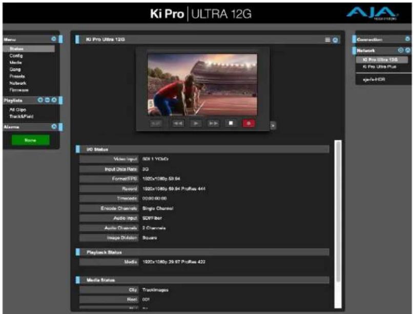
text_image
Ki Pro | ULTRA 12G KC Pro Ultra 12G UO Status Video Input 800.1 Vdcu Input Data Ret: 3G Format/TPD 1920x1086p 59.94 Record 1920x1086p 59.94 ProRes 444 Timecode 00:00:00:00 Encode Channels Single Channel Audio Input SUIFiber Audio Channels 3 Channels Image Dividers Squares Playback Status Media 1920x1086p 29.97 ProRes 422 Media Status Cig TrackImages Reel 001Overview
An optimized web server running on Ki Pro Ultra 12G allows you to remotely monitor and adjust parameter settings via a browser client running on a network wired computer. The network can be a closed local area network, a straight computer-to-Ki Pro Ultra 12G cable connection, or even exposed through a firewall to a broadband WAN.
NOTE: Exposing Ki Pro Ultra 12G on a broadband WAN is not generally recommended since anyone on the Internet could potentially access Ki Pro Ultra 12G.
The LAN connection on Ki Pro Ultra 12G uses a standard RJ-45 connector, but internally it's intelligent and communicates via standard "straight-through" CAT 5 Ethernet cables or null-modem (cross-over) cables without any configuration or strapping required.
Preferred web browsers for Ki Pro Ultra 12G control include:
Mac OS
- Chrome
- Safari
- Firefox
Windows OS
- Chrome
- Firefox
NOTE: Other web browsers may work, but AJA cannot guarantee consistent operation for all web browsers or web browser versions. If you do experience an unexpected behavior when using a particular web browser or web browser version to interact with Ki Pro Ultra 12G, consider using an alternate web browser and report any issues experienced to AJA Technical Support.
To control Ki Pro Ultra 12G remotely, connect a computer to the Ki Pro Ultra 12G LAN connector, an RJ-45 socket, via a CAT5 Ethernet cable.
To access Ki Pro Ultra 12G, enter its URL in the web browser. The URL will be the IP address defined in Ki Pro Ultra 12G Network parameter menus (Note that Config menu parameters 50.1 through 50.4 must all be configured correctly to access Ki Pro Ultra 12G on your network). If Ki Pro Ultra 12G is using DHCP (the default), the IP address can be found by going to parameter 50.2 and reading it there. When Ki Pro Ultra 12G is shipped from the AJA factory, it defaults to DHCP operation. The DHCP selection is most useful in studio settings where the camera or cameras may be connected to an existing IT infrastructure.
If 50.1 is set to DHCP, and the DHCP server on the network fails to grant an IP address, then Ki Pro Ultra 12G 50.2 DHCP Address menu parameter will display 0.0.0.0. No connection to the device can be made with this address. Check with your network administrator if you experience issues connecting to the device over a DHCP network.
If 50.1 is set to Default Addr, the factory default static IP address 10.65.74.65 is used. So, if 50.1 is set to Default Addr, to see Ki Pro Ultra 12G web interface, you would type the following in the web browser:
http://10.65.74.65
NOTE: Your computer or network must be configured to access this IP address. You may need to make changes to your network settings on your host computer to access this IP address.
Figure 13. Default IP Address Configuration

text_image
Network Show All Location: Automatic Thund...thernet Connected AJA Mi...nverter Not Configured Display...ernet 2 Not Connected USB Ethernet 2 Not Connected Thund...FireWire Not Connected Wi-Fi Off Bluetooth PAN Not Connected Thund...t Bridge Not Connected Status: Connected Thunderbolt Ethernet is currently active and has the IP address 10.65.74.64. Configure IPv4: Manually IP Address: 10.65.74.64 Subnet Mask: 255.255.255.0 Router: DNS Server: Search Domains: Advanced... Assist me... Revert ApplyFor direct connections between a computer and Ki Pro Ultra 12G, you may elect to use the Static Addr selection. This allows you to select an IP address for Ki Pro Ultra 12G and apply it. For example, you could enter 192.168.0.2 as an IP address. Then, to see Ki Pro Ultra 12G web interface, you would type the following in the web browser:
http://192.168.0.2
NOTE: Your computer or network must be configured to access this IP address. You may need to make changes to your network settings on your host computer to access this IP address.
NOTE: If you change the Static IP address of the Ki Pro Ultra 12G camera, you may need to power cycle the Ki Pro Ultra 12G so that the host computer correctly identifies the new IP address.
Figure 14. Static IP Address Configuration
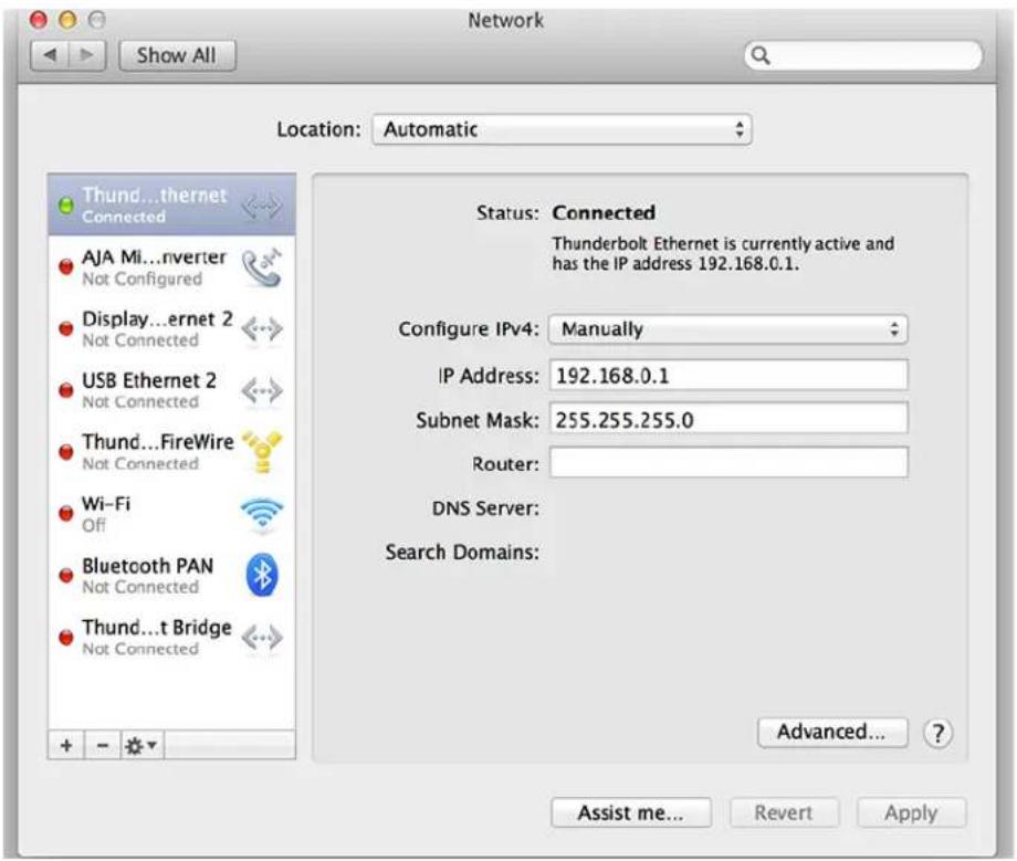
text_image
Network Show All Location: Automatic Thund...thernet Connected AJA Mi...nverter Not Configured Display...ernet 2 Not Connected USB Ethernet 2 Not Connected Thund...FireWire Not Connected Wi-Fi Off Bluetooth PAN Not Connected Thund...t Bridge Not Connected Status: Connected Thunderbolt Ethernet is currently active and has the IP address 192.168.0.1. Configure IPv4: Manually IP Address: 192.168.0.1 Subnet Mask: 255.255.255.0 Router: DNS Server: Search Domains: Advanced... Assist me... Revert ApplyAll Ki Pro Ultra 12G web screens have certain areas in common. On the left of each screen is a Menu panel listing all the available Ki Pro Ultra 12G screen choices. Click any of these items to jump to that screen. On the right side of each screen you'll also find a Connection panel. This area shows the connection status and Ki Pro Ultra 12G serial number and software version. This latter information is useful if you ever have to call AJA Technical Support to discuss a problem or get help.
Figure 15. Ki Pro Ultra 12G Web UI Config Screen, Single Channel Mode
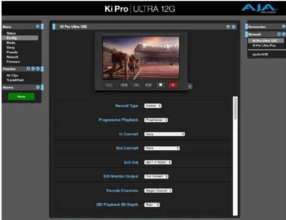
text_image
Ki Pro | ULTRA 12G KI Pro Ultra 12G Record Type Normal $ Progressive Playback Progressive $ In Convert None $ Out Convert None $ SDI Out SDI 1.4 VCDOR $ SDI Monitor Output Cut Convert $ Encode Channels Single Channel $ SDI Playback Bit Depth Auto $ Connection Network Ki Pro Ultra 12G Ki Pro Ultra Plus ag-fit-HCR Memo Status Config Media Gang Proceeds Network Firmware Playlists All Clips Track&Field Alarms NoneBelow the Connection panel, the Network panel shows the Ki Pro Ultra 12G systems on the network and allows you to switch control between systems. See "Gang Recording" on page 70 for additional information.
In the middle of each screen are menu choices and information pertaining to the subject matter of that screen. At the top of each screen is an emulation of the Ki Pro Ultra 12G user interface.
Ki Pro Ultra 12G web screens closely mirror the parameter menus displayed on its front panel.
If you are unsure about the operation of a menu parameter, hovering your mouse over the parameter name will bring up a tooltip for that parameter. Additionally, a pulldown menu above the emulation of the Ki Pro Ultra 12G user interface area allows you to turn on tooltips for the buttons in this area.
The buttons in this area can also be used to access the menu parameters in the same way that the menu bar on the left hand side of the UI may be used. The transport buttons in this area may be used for clip playback operation. The UI Control Knob emulation in this area may be clicked to toggle from navigating clips to a jog playback mode. To navigate or jog, use a scroll wheel-based mouse or swipe up or down on a trackpad.
Figure 16. Ki Pro Ultra 12G Web UI Config Screen, Multi Channel Mode
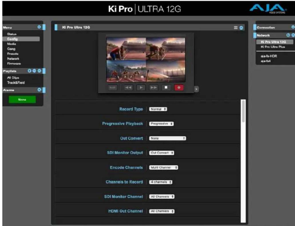
text_image
Ki Pro | ULTRA 12G Ki Pro Ultra 12G Record Type Normal $ Progressive Playback Progressive $ Out Convert None $ SDI Monitor Output Out Convert $ Encode Channels Multi Channel $ Channels to Record 4 channels $ SDI Monitor Channel All Channels $ HDMI Out Channel All Channels $ Connection Network Ki Pro Ultra 12G Ki Pro Ultra Plus aia-fs-HDR aja-fst Menu Status Config Media Gang Projects Network Firmware Playlists All Clips Track&Field Alarme NoneThe Single Channel and Multi Channel mode Config screens have different parameters, as described in "Chapter 4 Front Panel Operation" on page 25.
Operations Unique to the Web UI
Playing, Jogging and Selecting Clips
Clicking on the blue arrow icon on the top right of the screen opens and closes a Transport pane. A graphical representation of the Ki Pro Ultra 12G front panel is shown, with operational transport buttons. Simply click on a button to rewind, play, fast forward, stop, or a loaded clip, or record a new clip.
Clicking on the small gray arrow on the lower right opens a JOG/Clips control. Clicking on that control toggles between JOG and Clips operation.
Figure 17. JOG Control
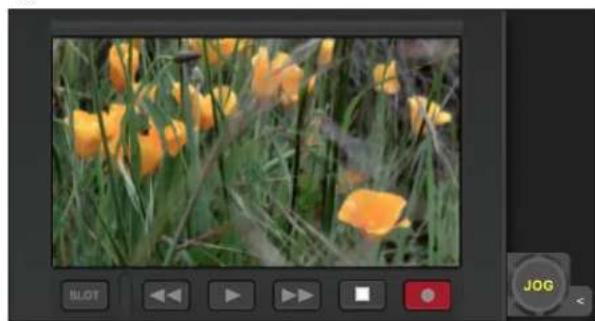
natural_image
Photo of yellow tulips in a grassy field, captured within a video player interface (no text or symbols on the image itself)With JOG selected (Figure 17), hovering the cursor over the icon allows jogging the currently loaded clip forwards and backwards one frame at a time using the scroll wheel on your mouse (if so equipped).
Figure 18. Clips Control
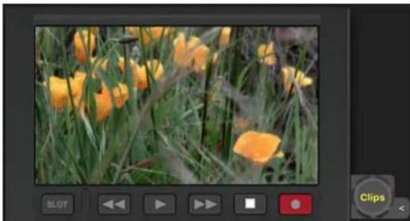
natural_image
Photo of yellow tulips in a grassy field, captured within a video player interface (no text or symbols on the image itself)With Clips selected (Figure 18), hovering the cursor over the icon allows you to scroll through the clips currently available using the mouse's scroll wheel.
Playlists
AJA provides tools for reviewing clips and creating playlists of clips. These clip playlists can be managed on the web browser Playlists screen, which includes a default All Clips playlist showing all clips on the Ki Pro Ultra 12G unit.
Figure 19. All Clips Playlist Screen
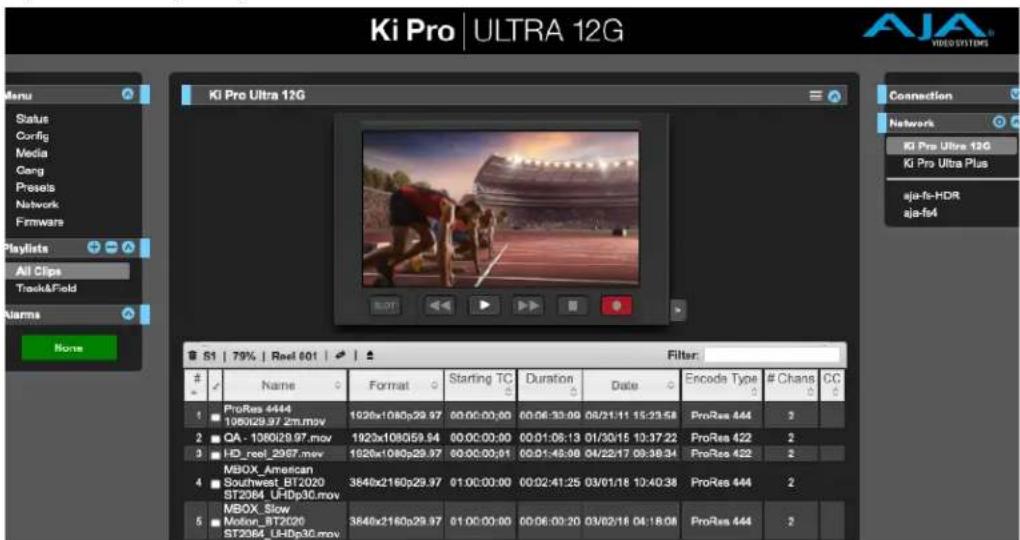
text_image
Ki Pro | ULTRA 12G KI Pro Ultra 12G Menu Status Config Media Carg Preseis Network Firmware Playlists All Clips Track&Field Alarms None Connection Network Ki Pro Ultra 12G Ki Pro Ultra Plus aja-fs-HDR aja-fs4 S1 | 79% | Reel 601 | Filter:Name Format Starting TC Duration Date Encode Type # Chans CC
1 ProRes 444 108029.97 zm.mov 1020x1080p29.97 00:00:00:00 00:06:33:09 08/21/11 15:23:58 ProRes 444 2 2 QA - 108029.97.mov 1920x1080p59.94 00:00:00:00 00:01:06:13 01/30/15 10:37:22 ProRes 422 2 3 HD_reel_2987.mov 1620x1080p29.97 00:00:00:01 00:01:45:36 04/22/17 09:38:34 ProRes 422 2 4 MBOX_American Southwest_BT2020 ST2064_UFIDp3C.mov 3840x2160p29.97 01:00:00:00 00:02:41:25 03/01/16 12:40:38 ProRes 444 2 5 MBOX_Slow Motion_BT2020 ST2064_UFIDp3C.mov 3840x2160p29.97 01:00:00:00 00:06:00:20 03/02/16 04:18:08 ProRes 444 2The default state of the Playlists is to list All Clips available. All Clips represents all of the recordings made on the Ki Pro Ultra 12G or valid files transferred to the Ki Pro Ultra 12G.
Quick Cueing
You can cue up a clip quickly for review by simply double-clicking the clip in the list. Note that once you've double-clicked a clip to select it, it will be highlighted in blue in the list and the first frame of video from that clip will appear on the output of the Ki Pro Ultra 12G. To play back the clip, simply open the Transport page of the web UI and begin playback with the Play button. Or you can use the "mini-player" from within the playlist. You can also quickly scan material by setting the Media>Play Media>All selection so that as you highlight clips for review, they will continue playing out of the Ki Pro Ultra 12G outputs.
Creating Playlists
In the Playlists portion of the web UI, there is a "+" symbol and a "-" symbol above the lists. The "+" symbol can be used to add a playlist. Simply click on this symbol and, when prompted, enter a name for the playlist you wish to create. To add clips to a playlist, select a blue highlighted clip from the All Clips list and click and drag the clip onto the name of the playlist you created.
NOTE: When you select a clip and click and drag it, a filmstrip icon will appear. If you do not see this icon, then you have not selected a clip.
You can tell that a clip will be added to a playlist because the list you drag the clip to will be highlighted in green and the filmstrip icon will appear with a "+" symbol on the left side. When you release the mouse, the clip will be added to the playlist. You may select additional clips using the same method and add them to the playlist.
To move a number of clips to a playlist at once, use the column with the checkmark and tick the checkboxes of the clips prior to performing the click and drag to the list.
To review your playlist, click on the list in the Playlists area of the web UI.
Change the Order of Clips
To reorder clips within a list, just click and drag them. You will notice that the clip is selected because the filmstrip icon will appear and you will know that a reorder is happening when you see the green highlight appear.
A clip cannot be moved to the last position of the playlist. To move a clip to the last position in the playlist, move it to the next to last position in the list and move the last clip in the list above it.
You may create multiple playlists. Playlists are stored as a simple file on the Ki Pro Ultra 12G media alongside the clips.
If you want to play a playlist you have created, first select Play Media>Playlist in the Media menu parameters.
NOTE: Depending on whether you have been reviewing clips, you may first be prompted to "Press Stop" prior to entering the Media page to make Playlist selections; if this prompt appears, you will be led to the Transport page where you can depress stop and then enter the Media page.
Select a playlist from the Playlist parameter in the Media menu. Once a playlist is selected, you will notice that a double arrow indication will appear next to the selected list in the Playlists portion of the web UI. If you go to the Transport portion of the web UI, you will now notice that the playlist is cued up, ready for playback of the first clip in the list. If you want to navigate within your list, you may use the fast forward and rewind buttons or the select up/down buttons. You can loop playback of a list using the Media menu parameters as well.
Management of the playlists is made possible via the web UI; creation and management of playlists from the front panel is not supported. An indication of a selected playlist is presented on the front panel UI via menu parameter 15.3 Playlist. The selection of a playlist does not survive reboots of the unit, but the playlists that are created do survive reboots.
Gang Recording
At-a-glance you can see all of the Ki Pro Ultra 12G systems that are present on the same local LAN in the Connection section of the web UI. Their system names are shown in the Network panel on the right side of the screen.
Figure 20. Gang Recording Screen
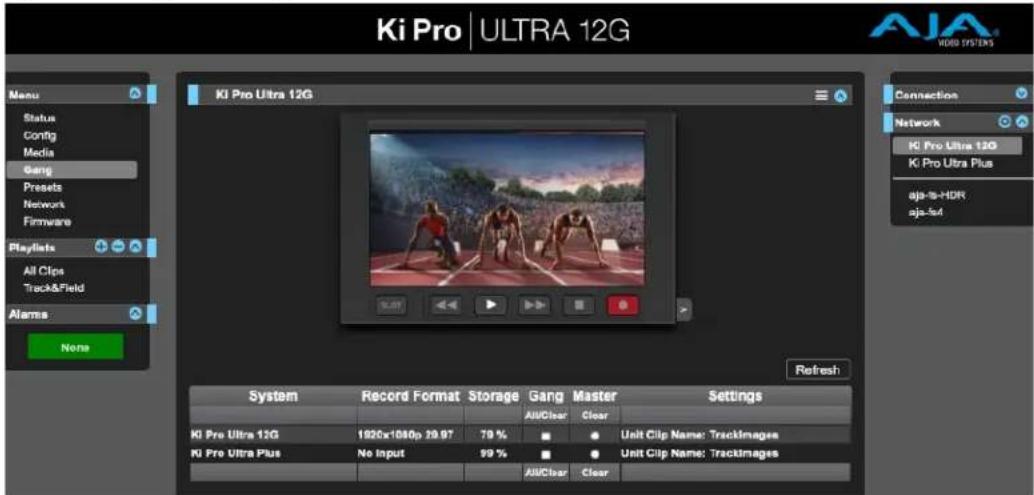
text_image
Ki Pro | ULTRA 12G KI Pro Ultra 12G System Record Format Storage Gang Master Settings AllClear Clear Ki Pro Ultra 12G 1920x1080p 39.97 79 % Ki Pro Ultra Plus No Input 99 % AllClear Clear Connection Network Ki Pro Ultra 12G Ki Pro Ultra Plus ajs-Is-HDR aja-Is4 Alarms None Refresh AuClear ClearClick a system name to switch the browser to that particular Ki Pro Ultra 12G system.
NOTE: You must have a properly configured default gateway to see the Ki Pro Ultra 12Gs. If the Default Gateway (parameter 50.4) is not configured properly, other Ki Pro Ultra 12Gs will not be listed.
Multiple Ki Pro Ultra 12G units can be used in unison to produce recordings via the Gang Control feature. This feature is only available via the web UI when Ki Pro Ultra 12G units have IP addresses configured under a common network and subnet mask and are connected via their LAN connections to an Ethernet switch or hub to a host computer. AJA recommends that all Ki Pro Ultra 12G units in a gang use the same firmware version.
Example
You have a Ki Pro Ultra 12G "Master" a Ki Pro Ultra 12G "Subordinate" both attached on a network where their static IP addresses are 192.168.0.2 and 192.168.0.3, both with a subnet mask value of 255.255.255.0. They are connected to a host computer with IP address 192.168.0.1 and subnet mask 255.255.255.0. The host computer uses a web browser, like Apple's Safari, to access the "Master" Ki Pro Ultra 12G by entering 192.168.0.2 in the URL field of the browser. The Ki Pro Ultra 12G "Master" unit web UI should appear. Locate the Gang Controls area in the user interface.
Parameters for each available Ki Pro Ultra 12G will appear in the Gang Controls area. These include:
- System – displays Ki Pro Ultra 12G units that may be added to a gang
- Record Format – type of video format/frame rate each system is configured to record
- Free Storage – at-a-glance view of the capacity of the media in each unit
- Gang – units can be added or removed from the gang
- Master – allows the promotion of a Ki Pro Ultra 12G unit to the controlling role
- Settings – allows for the configuration of clip names on the Master and Subordinate Ki Pro Ultra 12G units
To add a Ki Pro Ultra 12G to a gang, simply select the check box for the unit in the Gang column. As a shortcut, if all available Ki Pro Ultra 12G units are desired for a gang, select the All item below Gang. If you want to clear units from a gang, deselect them or use the Clear option.
There can be only one Master in a gang; typically, the IP address for the Ki Pro Ultra 12G unit you entered and are viewing the web UI on is the one which should be promoted to the controlling role. If the unit with the IP address that is currently being viewed via the web UI is selected, a red capitalized MASTER text will appear on the web page above the columns.
A Master Ki Pro Ultra 12G unit can send three items to the subordinate Ki Pro Ultra 12G units within a gang; a record start command, a stop command, and clip naming.
The Settings area is where the Ki Pro Ultra 12G clip name for each unit is decided. By default, Ki Pro Ultra 12G is configured to use the standard clip naming conventions, not the custom clip naming conventions. The first user selection is Use Custom Clip Name; if you want to use the standard clip naming convention, leave this set to OFF, but if you want to create a custom clip name, mouse click on the OFF to reveal a pulldown for OFF/ON selection then click OK. If OFF was selected, the next parameter would be Clip Name, again, clicking on the SC or Clip presented brings up the pulldown and the OK box. Clip Number must be entered manually with a valid value for Ki Pro Ultra 12G of 1 through 999 and then the enter/return key must be hit. If the enter/return key is not entered after the selection, the value will revert to whatever was previously shown.
Clicking on the value next to Clip Append and Alpha Append both bring up a pulldown and an OK button. Take operates like the Clip Number, where a valid value of 1 to 999 can be entered and the enter/return key needs to be hit for confirmation of the value. For custom clip naming considerations, see "Custom Clip Naming" on page 42.
Note that for Subordinate Ki Pro Ultra 12G units, the Settings column provides a selection of either Use: Master Name or Subordinate Name. Clicking on the default value of Master Name pulls up a pulldown selection of Master Name or Subordinate Name with an OK confirmation button. If the desire is to have clips named the same across all Ki Pro Ultra 12G units' recordings, then select Use: Master Name. If the desire is to have clips named independently on Ki Pro Ultra 12G units, then select Subordinate Name. Selecting Subordinate Name means that the recording will take it's name from the individual Ki Pro Ultra 12G's parameters and not accept the value pushed to the Subordinate by the Master Ki Pro Ultra 12G.
NOTE: Ki Pro Ultra 12G can initiate recordings among units quickly, but not all units will begin or end recordings precisely at the same time or the same frame. This is not an issue if matching timecode via LTC or RP188.
NOTE: Ki Pro Ultra 12G does not provide simultaneous playback of media; only record start and stop functions are available.
Data Transfer via LAN
There are two ways to access Data Transfer mode:
- Use the Ki Pro Ultra 12G front panel UI to set Media State to Data-LAN (see Figure 21 on page 73 and "12.1 Media State" on page 35).
- Access the Playlist web page and the All Clips mode then click on the media state toggle icon.
Appropriately encoded files may be uploaded to the Ki Pro Ultra 12G or downloaded from the Ki Pro Ultra 12G.
Figure 21. Data LAN Screen
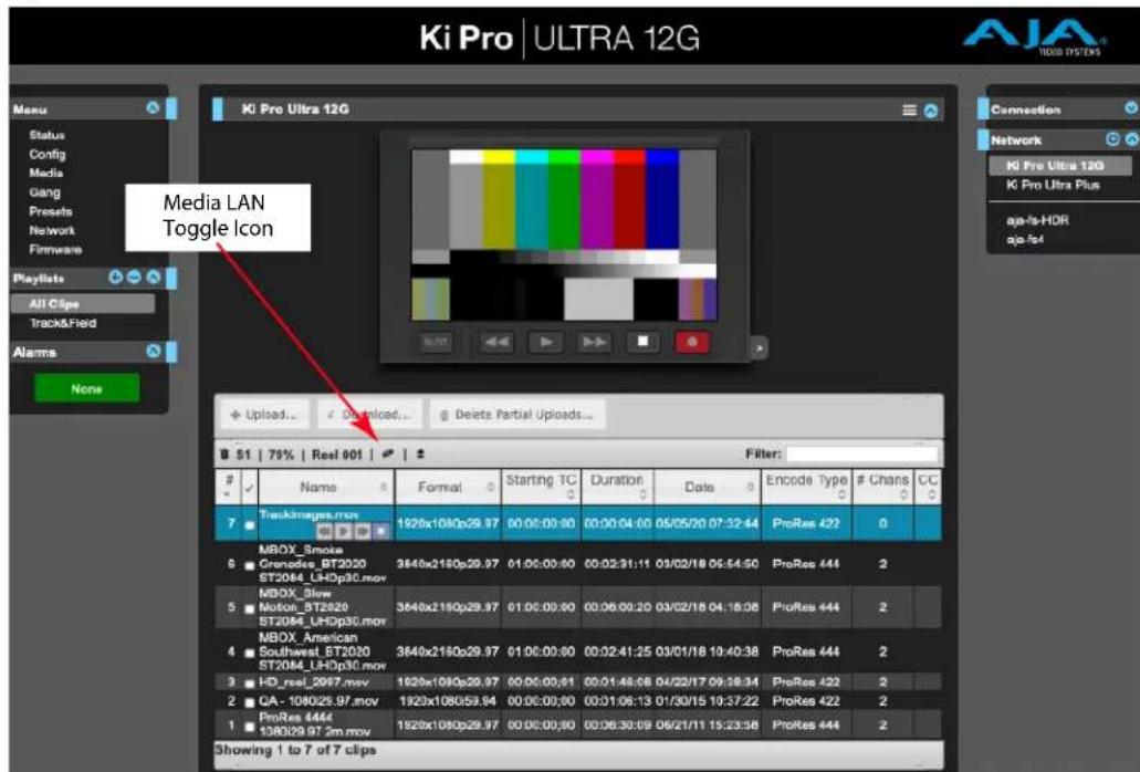
text_image
Ki Pro | ULTRA 12G Media LAN Toggle Icon Hi Pro Ultra 12G B 51 | 75% | Reel 001 | Filter:Name Format Starting TC Duration Date Encode Type # Chans CC
7 TrackImages.mov 1920x108p29.97 00:00:00:00 00:00:04:00 05/05/20 07:32:44 ProRes 422 0 MBOX Smoke Cronodes_BT2020 3840x218p29.97 01:00:00:00 00:02:31:11 03/02/18 05:54:50 ProRes 444 2 ST2084_LHDp3c.mov MBOX Slow Motor_BT2820 3840x218p29.97 01:00:00:00 00:06:00:20 03/02/18 04:18:08 ProRes 444 2 ST2084_LHDp3c.mov MBOX_American Southwest_BT2020 3840x218p29.97 01:00:00:00 00:02:41:25 03/01/18 10:40:38 ProRes 444 2 ST2084_LHDp3c.mov HD_real_2997.mov 1920x108p29.97 00:00:00:01 00:01:48:58 04/22/17 09:38:34 ProRes 422 2 QA-108028.97.mov 1920x108p59.94 00:00:00:00 00:01:06:13 01/30/15 10:37:22 ProRes 422 2 ProRes 444 108028.97 2m.mov 1920x108p29.97 00:00:00:00 00:06:30:09 06/21/11 15:23:58 ProRes 444 2 Showing 1 to 7 of 7 clipsDuring an upload, useful information about the upload is given: the name of the file being uploaded, the size of the file being uploaded, a progress bar and a Cancel button. Additionally transfer speed information, remaining time to transfer and percentage of data transferred are shown.
NOTE: If an upload is canceled or interrupted for any reason, the transfer may be resumed by selecting the clip that was transferring again and re-starting the transfer. If you have canceled some uploads, you may regain the space that these partial uploads may occupy on them media by choosing the Delete Partial Uploads option.
To download a clip, select the Download option. Note that the file will be downloaded to the particular web browser's selected download location.
See "Appendix A Specifications" on page 79 for a complete list valid media files that can be copied to Ki Pro Ultra 12G. Files copied to Ki Pro Ultra 12G that do not meet these criteria may not appear in the web UI or front panel UI when you review clips.
NOTE: Not all combinations of formats, frame rates and codecs are supported.
Presets
The Presets screen allows you to save Preset Configurations into 20 separate memory registers and recall the presets whenever needed.
Figure 22. Presets Screen
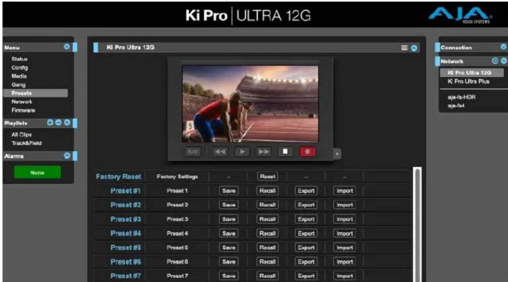
text_image
Ki Pro | ULTRA 12G Ki Pro Ultra 12G Factory Reset Factory Settings - Reset - - Preset #1 Preset 1 Save Recall Export Import Preset #2 Preset 2 Save Recall Export Import Preset #3 Preset 3 Save Recall Export Import Preset #4 Preset 4 Save Recall Export Import Preset #5 Preset 5 Save Recall Export Import Preset #6 Preset 6 Save Recall Export Import Preset #7 Preset 7 Save Recall Export ImportThis screen also includes Export and Import functions that allow exporting one or all presets to your computer as files and importing exported preset files from your computer. A displayed message indicates successful or failed saves, recalls, exports, and imports.
Save Buttons
The Save buttons let you save the current configuration into the preset register with the associated name and number. A preset is a set of system parameters as they were set at the time the preset was stored. Only editable parameters are saved in the presets. Non- editable parameters are not saved.
To change a preset name, click in the name's text field and type a new name. Then press Enter.
When you recall a Preset Configuration, the recalled preset immediately replaces the system's existing configuration. All previous settings are lost unless you have previously stored them in another preset configuration or an exported file.
Import Buttons
The Import buttons let you browse for and import a preset file on your computer into the preset register associated with the selected button. A dialog box warns you that the operation will overwrite the current preset contents with the contents stored in the file.
Import Presets 1-20 lets you browse for and import a previously exported "all. presets" file from your computer. A dialog box warns you that the operation will overwrite all 20 current preset contents with the contents stored in the file.
Export Buttons
The Export buttons save the associated preset contents to a file on your computer. The file gets exported to the default download location specified in your browser options. The file name is the same as the preset name with the suffix .presets. If you export multiple files for the same preset, a number gets appended to ensure a unique file name. The file size is small, usually less than 10 kilobytes.
Export Presets 1-20 lets you save the contents of all presets to a file on your computer. The file gets exported to the default download location specified in your browser options with the name "all.presets". If you export multiple files, a number gets appended to ensure a unique file name.
Recall Factory Preset
Recall Factory Preset recalls all editable video and audio parameters to their factory default settings. Individual presets, user preferences, and Network settings, such as the IP Address, are not affected.
Updating Firmware
The Update Firmware screen allows you to update your Ki Pro Ultra 12G to later versions of software as they are issued by AJA and posted on the website. When software updates are released, they often contain new features, improvements, and bulletins that may be very useful. We suggest checking the website when you have time.
Figure 23. Update Firmware Screen
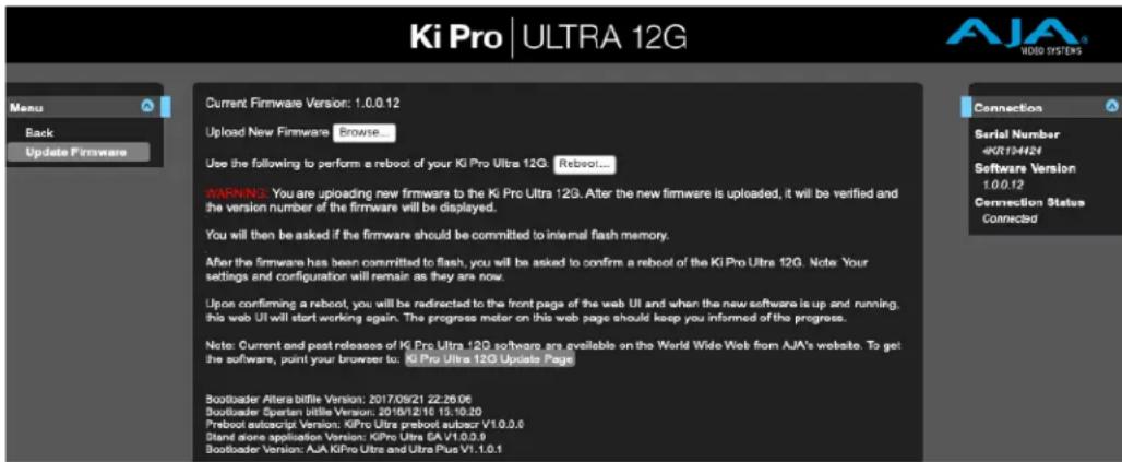
text_image
Ki Pro | ULTRA 12G AJA® VIDEO SYSTEMS Menu Back Update Firmware Current Firmware Version: 1.0.0.12 Upload New Firmware Browse Use the following to perform a reboot of your Ki Pro Ultra 12G Reboot... WARNING: You are uploading new firmware to the Ki Pro Ultra 12G. After the new firmware is uploaded, it will be verified and the version number of the firmware will be displayed. You will then be asked if the firmware should be committed to internal flash memory. After the firmware has been committed to flash, you will be asked to confirm a reboot of the Ki Pro Ultra 12G. Note: Your settings and configuration will remain as they are now. Upon confirming a reboot, you will be redirected to the front page of the web UI and when the new software is up and running, this web UI will start working again. The progress meter on this web page should keep you informed of the progress. Note: Current and past releases of Ki Pro Ultra 12G software are available on the World Wide Web from AJA's website. To get the software, point your browser to: Ki Pro Ultra 12G Update Page Bootbader Altera bittle Version: 2017/09/21 22:26:06 Bootbader Speran bittle Version: 2018/12/16 15:10:20 Preboot autascript Version: KIPro Ultra preboot autscr V1.0.0.0 Stand alone application Version: KIPro Ultra SA V1.0.0.0 Bootbader Version: AJA KIPro Ultra and Ultra Plus V1.1.0.1 Connection Serial Number 4KR134424 Software Version 1.0.0.12 Connection Status ConnectedAlthough Ki Pro Ultra 12G comes from the factory pre-installed with software, it may not be as up-to-date as the software currently posted on the AJA website. This topic describes the steps required to upgrade the software in your Ki Pro Ultra 12G.
NOTE: AJA recommends a Factory Reset under the Config menu prior to updating firmware.
- Download the Latest Ki Pro Ultra 12G firmware.
Current and past releases of Ki Pro Ultra 12G firmware are available from AJA's website. To get the firmware, point your browser to:
https://www.aja.com
Access the support page and once you're at the update page, select the Ki Pro Ultra 12G firmware files for Mac or PC for download.
- Unpack the Software
Ki Pro Ultra 12G software update files are "ZIP" files, which you can open with a number of standard and third-party applications. In some cases, these files may "decompress" automatically, such as when using Safari and Mac OS X. The firmware image that you'll install on Ki Pro Ultra 12G is a file with a name like KiProUltra12G_1.0.0.100.bin or similar.
Depending on your PC or Mac operating system settings, the ".bin" extension may not be visible to you in a file directory.
Uploading and installing the firmware update only requires a PC or Mac that can "see" the Ki Pro Ultra 12G via its Ethernet connection. To install the firmware:
-
Be sure that you have configured your IP address information so that you can see Ki Pro Ultra 12G with your web browser.
-
Once you have entered Ki Pro Ultra 12G's IP address, choose the "Update Firmware" page link on the left side of any Ki Pro Ultra 12G web page.
-
Click the "Browse..." button to select the file you previously downloaded. For example: Ki ProUltra_1.0.0.153.bin file.
-
When you have selected a valid Ki Pro Ultra 12G .bin image file, click the "Upload" button in the web browser.
The file you select will upload to Ki Pro Ultra 12G and be tested for validity. Incomplete, corrupted, or non-Ki Pro Ultra 12G firmware files will be rejected.
- Agree to the steps and confirmation prompts as they are presented. Wait for the procedure to complete—it will take only a few minutes.
When done, Ki Pro Ultra 12G will prompt you to restart your machine. After restart, Ki Pro Ultra 12G will be running the new software. Progress is shown on the front panel.
-
Once these steps are complete, Ki Pro Ultra 12G will be running the firmware you just uploaded until the next time you upgrade it.
-
AJA strongly recommends performing a factory reset after updating Ki Pro Ultra 12G firmware.
NOTE: You may ensure the new software is running by bringing up the Ki Pro Ultra 12G web page again. The software version is displayed at the top of all web screens. If for some rare reason it didn't update, you can then run through the update steps again.
NOTE: On some browsers, the Retry page may appear even though the firmware upgrade was successful. If this occurs, before clicking on retry, refresh the web page and check the version number. If the new version number appears at the top of the page, the firmware upgrade was successful. If the old version appears, click Retry.
If there is a power outage or glitch during the firmware download, Ki Pro Ultra 12G will boot the older software version and the upgrade process can then be re-started. This happens because Ki Pro Ultra 12G has been designed with a safety feature where an internal "safe" copy of the previous software is retained in the event the updating process fails.
CAUTION: AJA recommends you only update the Ki Pro Ultra 12G when on mains power, or with a fully charged battery.
Chapter 6 – Ki Pro Ultra 12G Accessories
Overview
Ki Pro Ultra 12G's design allows a variety of accessories to be used with the device. AJA provides some of these accessories as optional items that may be purchased separately. The Ki Pro Ultra 12G's handle and desktop feet are included with the unit and, if wanted, are easily installed.
Ki Pro Ultra 12G Handle
For units that will be moved often, AJA offers the sturdy handle option.
Figure 24. Ki Pro Ultra 12G with Handle
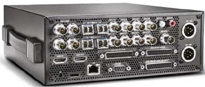
natural_image
Front view of a black electronic device chassis with ports, connectors, and ventilation grilles (no visible text or labels)Figure 25. Ki Pro Ultra 12G Handle Assembly
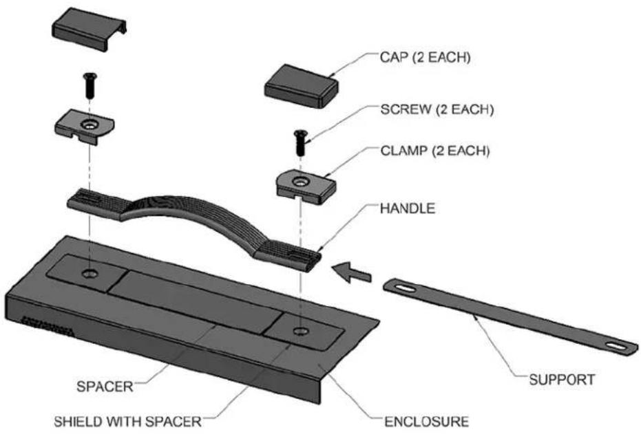
text_image
CAP (2 EACH) SCREW (2 EACH) CLAMP (2 EACH) HANDLE SPACER SHIELD WITH SPACER ENCLOSURE SUPPORT-
Remove the two screws from the right side of the enclosure and keep for reuse.
-
Place the Shield with Spacer (temporary) on top of the Enclosure, aligning the holes.
- Slide the Support into the Handle.
- Place the Handle on top of the Shield, aligning the holes.
- Place the Clamps on top of the Handle, aligning the holes.
- Insert the two screws through the Clamps, Handle, Support, and Shield and into the enclosure.
- Snap the Caps over the Clamps and tear away the Spacer from the Shield.
KPU-Shelf
AJA offers this rackmount shelf accepting two Ki Pro units in a 2RU footprint.
Figure 26. Ki Pro Ultra 12G in Rackmount Shelf

text_image
AIA AIA K Pro Ultra 12G Simpia 300000 Buffers Ki Pro ULTRA 12G AIA 15-2 Cusipas City Name 15-2 CUSIPAS City Name Ki Pro ULTRA Plus AIA K Pro Ultra 12G Simpia 300000 Buffers Ki Pro ULTRA Plus AIA K Pro Ultra 12G Simpia 300000 Buffers Ki Pro ULTRA Plus AIA K Pro Ultra 12G Simpia 300000 Buffers Ki Pro ULTRA Plus AIA K Pro Ultra 12G Simpia 300000 Buffers Ki Pro ULTRA Plus AIA K Pro Ultra12G Simpia 300000 Buffers Ki Pro ULTRA Plus AIA K Pro Ultra12G Simpia 300000 Buffers Ki Pro ULTRA Plus AIA K Pro Ultra12G Simpia 300000 Buffers Ki Pro ULTRA Plus AIA K Pro Ultra12G Simpia 300000 Buffusers Ki Pro ULTRA Plus AIA K Pro Ultra12G Simpia 300000 Buffusers Ki Pro ULTRA Plus AIA K Pro Ultra12G Simpia 300000 Buffusers Ki Pro ULTRA Plus AIA K Pro Ultra12G Simpia 300000 Buffusers Ki Pro ULTRA Plus AIA K Pro Ultra12GSFP Modules
See https://www.aja.com/software/configurator for an online tool you can use to select compatible SFP modules.
Ki Pro Ultra 12G Tech Specs
Video Formats
- Single Channel Mode:
• (4K) 4096 x 2160p 23.98, 24, 25, 29.97, 30, 50, 59.94, 60
• (4K) 4096 x 2160PsF 23.98, 24, 25, 29.97*
• (UltraHD) 3840 x 2160p 23.98, 24, 25, 29.97, 30, 50, 59.94, 60
• (UltraHD) 3840 x 2160PsF 23.98, 24, 25, 29.97*
• (2K) 2048 x 1080p 23.98, 24, 25, 29.97, 30, 50, 59.94, 60
• (HD) 1080p 23.98, 24, 25, 29.97, 30, 50, 59.94, 60
• (HD) 1080i 25, 29.97, 30
• (HD) 1080PsF 23.98, 24, 25**, 29.97**
• (HD) 720p 50, 59.94, 60
- Multi-Channel Mode:
• (HD) 1080p 23.98, 24, 25, 29.97, 30, 50, 59.94, 60
• (HD) 1080i 25, 29.97, 30
• (HD) 1080PsF 23.98, 24, 25**, 29.97**
• (HD) 720p 50, 59.94, 60
*Only 4x 1.5G-SDI, 10-bit 4:2:2 YCbCr, Square Division
**25 and 29.97 requires Record Type>PsF selection
Codec Support
- Single Channel Mode:
• Apple ProRes 4444 XQ, up to 2K/60 fps
• Apple ProRes 4444, up to 30 fps
• Apple ProRes 422 (HQ) - Apple ProRes 422
• Apple ProRes 422 (LT)
• Apple ProRes 422 (Proxy)
• Avid DNxHD HQX (220x)*
• Avid DNxHD SQ (145)*
• Avid DNxHD LB (36)**
• Avid DNxHR HQX up to 4K/29.97 fps
• Avid DNxHR SQ up to 4K/29.97 fps
• Avid DNxHR LB up to 4K/29.97 fps
- Multi-Channel Mode:
• Apple ProRes 4444, up to 30 fps
• Apple ProRes 422 (HQ)
- Apple ProRes 422
• Apple ProRes 422 (LT)
• Apple ProRes 422 (Proxy)
*Avid DNxHD only supported for 1080 and 720 resolutions
**Avid DNxHD 36 only supported for 1080p
Codec Container
- Apple ProRes .MOV
• AVID DNX .MXF or .MOV
Removable Storage
• 2x slots, AJA SSD media Pak 2000, Pak 1000, Pak 512, Pak 256
File System Support
- HFS+, exFAT
Video Input Digital
• 1x 12G-SDI, SMPTE-292/372/424/2081/2082
• 3x 3G-SDI, SMPTE-292/372/424
• 1x Fiber or HD-BNC 12G-SDI, SMPTE-297 (optional SFP modules)
- 3x Fiber or HD-BNC, 3G-SDI, SMPTE-297 (optional SFP modules)
• 4K/UltraHD 4:2:2 10bit & 4:4:4 10/12bit (BNC or Fiber)
• Dual Link 4:2:2 10bit & 4:4:4 10/12bit (BNC or Fiber)
- Single Link 4:2:2 10bit & 4:4:4 10/12bit (BNC or Fiber)
- 1x HDMI standard type A connector
- HDMI v2.0
• 4:4:4 RGB 8/10/12-bit (deep color)
• 4:2:2 YCbCr 8/10/12-bit
• 4:2:0 YCbCr 8-bit
Video Output Digital
• 1x 12G-SDI, SMPTE-292/372/424/2081/2082
• 3x 3G-SDI, SMPTE-292/372/424
• 1x Fiber or HD-BNC 12G-SDI, SMPTE-297 (optional SFP modules)
• 3x Fiber or HD-BNC, 3G-SDI, SMPTE-297 (optional SFP modules)
• 4K/UltraHD 4:2:2 10bit & 4:4:4 10/12bit (BNC or Fiber)
• Dual Link 4:2:2 10bit & 4:4:4 10/12bit (BNC or Fiber)
- Single Link 4:2:2 10bit & 4:4:4 10/12bit (BNC or Fiber)
- 1x HDMI standard type A connector
- HDMI v2.0
• 4:4:4 RGB 8/10/12-bit (deep color)
• 4:2:2 YCbCr 8/10/12-bit
• 4:2:0 YCbCr 8-bit
Audio Input Digital
- 16-channel, 24-bit SDI/Fiber embedded audio, 48 kHz sample rate, synchronous
- 8-channel, 24-bit HDMI embedded audio, 48 kHz sample rate, synchronous
• 8-channel, AES/EBU via (1/2x DB-25 TASCAM pinout)
Figure 27. Digital Audio Connector Pinout
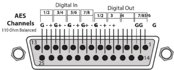
text_image
AES Channels 110 Ohm Balanced Digital In 1/2 3/4 5/6 7/8 G - + G+ - G - + G+ - G - + - + 13 25 Digital Out 1/2 3 4 7/85 6 GG GAudio Input Analog
- 8-channel, mappable, 24-bit A/D analog audio, 48 kHz sample rate (1x DB-25 TASCAM Pinout)
• +24 dBu full scale digital
• +/- 0.2 dB 20 Hz to 20 kHz frequency response
Figure 28. Analog Audio Connector Pinout
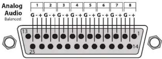
text_image
Analog Audio Balanced 1 2 3 4 5 6 7 8 G - + G - + G - + G - + G - + G - + 13 1 25 14Audio Output Digital
- 16-channel, 24-bit SDI/Fiber embedded audio, 48 kHz sample rate, synchronous
• 8-channel, 24-bit HDMI embedded audio, 48 kHz sample rate, synchronous
• 8-channel, AES/EBU via (1/2x DB-25 TASCAM pinout)
Audio Output Analog
- Stereo unbalanced headphone jack (1x 3.5mm jack) with volume control
- 8-channel, 24-bit D/A analog audio, 48 kHz sample rate (1x DB-25 TASCAM pinout)
• 2-channel unbalanced 2x RCA connectors
Recording Mode
- Multi-channel HD Apple ProRes recording (Pak 2000, Pak 1000, Pak 512 (R1 and above), Pak 256 (R1 and above))
• Single channel 4K/UltraHD/2K/HD recording
Playback Mode
• One channel of 4K/UltraHD/2K/HD at a time
Timecode
• SDI RP188/SMPTE 12M via SDI BNC
- LTC input (1x BNC)
- LTC output (1x BNC)
- TC Super Out
Reference Input
- External, 2x BNC
- Looping, nonterminating
- Input reference formats:
• (HD) Tri-level sync
• 720p 59.94
• 720p 50
• 1080i 59.94
• 1080i 50
• 1080p 23.98
• 1080PsF 23.98
• 1080p 24
• 1080PsF 24
• 1080p 25
• 1080PsF 25
• 1080p 29.97
• 1080PsF 29.97
• (SD) Analog composite
• 525i 59.94
• 625i 50
Network Interface
- 1x LAN connector (RJ-45 connector, 10/100/1000)
- Embedded web server for remote control
- Configuration and Transport Control via WEB Interface
• Video Confidence Monitor via Web Interface - Clip upload/download via Web Interface in DATA-LAN mode
- Remote control via REST
Machine Control
• RS-422, 1x DE-9 female connector, Sony 9-pin protocol
- 9-pin D-connector pinout is as follows:
1 GND
2 TX-
3 RX+
4 GND
5 No Connection
6 GND
7 TX+
8 RX-
9 GND
Shell GND
User Interface
- Rotary selector knob
• Dedicated, backlit transport controls and menu buttons - Large 1280x720 TFT LCD display with Video Monitor and Menu/Status Overlays
Closed Captioning Support
- CEA-708, CEA-608
Size (w x d x h)
- 8.64" x 9.34" x 3.31" (219.46 x 237.24 x 84.08 mm)
Weight
- 5.6 lbs (2.6 kg)
Power
• Dual, redundant, 5.4A max, 35W-60W typical-65W Max
• 100-240 VAC 50/60 Hz (adapter)
• 12-18Vdc 4-pin XLR (chassis)
Environment
- Safe Operating Temperature: 0 to 40 C (32 to 104 F)
- Safe Storage Temperature (Power OFF): -40 to 60 C (-40 to 140 F)
- Operating Relative Humidity: 10-90% noncondensing
- Operating Altitude: <3,000 meters (<10,000 feet)
Dimensions
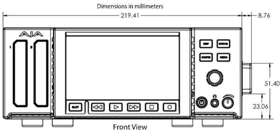
text_image
Dimensions in millimeters 219.41 8.76 51.40 23.06 Front View
text_image
219.41 84.13 Rear View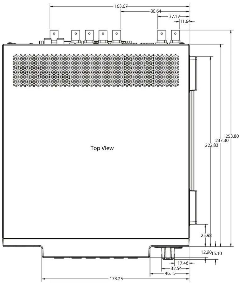
text_image
163.67 80.64 37.17 11.64 253.80 237.30 222.83 Top View 25.98 12.90 15.10 17.46 32.54 46.15 173.25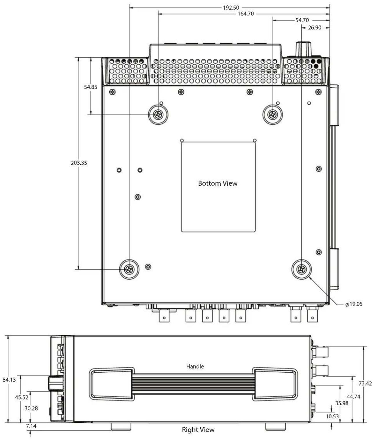
text_image
192.50 164.70 54.70 26.90 54.85 203.35 Bottom View Ø19.05 Handle 73.42 44.74 35.98 10.53 Right View 84.13 45.52 30.28 7.14Appendix B – Safety and Compliance
Federal Communications Commission (FCC) Compliance Notices
Class A Interference Statement
This equipment has been tested and found to comply with the limits for a Class A digital device, pursuant to Part 15, Subpart B of the FCC Rules. These limits are designed to provide reasonable protection against harmful interference in a commercial installation. This equipment generates, uses, and can radiate radio frequency energy and, if not installed and used in accordance with the instructions, may cause harmful interference to radio communications. However, there is no guarantee that interference will not occur in a particular installation. Operation of this equipment in a residential area is likely to cause harmful interference in which case the user will be required to correct the interference at his own expense. If this equipment does cause harmful interference to radio or television reception, which can be determined by turning the equipment off and on, the user is encouraged to try to correct the interference by one or more of the following measures:
- Reorient or relocate the receiving antenna.
- Increase the separation between the equipment and receiver.
- Connect the equipment into an outlet on a circuit different from that to which the receiver is connected.
- Consult the dealer or an experienced radio/TV technician for help.
FCC Caution
This device complies with Part 15 of the FCC Rules. Operation is subject to the following two conditions: (1) This device may not cause harmful interference, and (2) this device must accept any interference received, including interference that may cause undesired operation.
Canadian ICES Statement
Canadian Department of Communications Radio Interference Regulations
This digital apparatus does not exceed the Class A limits for radio-noise emissions from a digital apparatus as set out in the Radio Interference Regulations of the Canadian Department of Communications. This Class A digital apparatus complies with Canadian ICES-003.
European Union and European Free Trade Association (EFTA) Regulatory Compliance
This equipment may be operated in the countries that comprise the member countries of the European Union and the European Free Trade Association. These countries, listed in the following paragraph, are referred to as The European Community throughout this document:
AUSTRIA, BELGIUM, BULGARIA, CYPRUS, CZECH REPUBLIC, DENMARK, ESTONIA, FINLAND, FRANCE, GERMANY, GREECE, HUNGARY, IRELAND, ITALY, LATVIA, LITHUANIA, LUXEMBOURG, MALTA, NETHERLANDS, POLAND, PORTUGAL, ROMANIA, SLOVAKIA, SLOVENIA, SPAIN, SWEDEN, UNITED KINGDOM, ICELAND, LICHTENSTEIN, NORWAY, SWITZERLAND
Marking by this symbol indicates compliance with the Essential Requirements of the EMC Directive of the European Union 2014/30/EU.

This equipment meets the following conformance standards:
Safety
EN 60065: 2014 (T-Mark License)
IEC 60065: 2014 (CB Scheme Report/Certificate)
Additional licenses issued for specific countries available on request.
Emissions
EN 55032: 2012 + AC: 2013, CISPR 32: 2015,
EN 61000-3-2: 2014, EN 61000-3-3: 2013
Immunity
EN 55103-2: 2009, EN 61000-4-2:2009,
EN 61000-4-3:2006 + A1:2008 + A2:2010, EN 61000-4-4:2004 + A1:2010,
EN 61000-4-5:2006, EN 61000-4-6:2009, EN 61000-4-11:2004
Environments: E2, E3 and E4
The product is also licensed for additional country specific standards as required for the International Marketplace.

Warning! This is a Class A product. In a domestic environment, this product may cause radio interference, in which case, the user may be required to take appropriate measures.
This symbol on the product or its packaging indicates that this product must not be disposed of with your other household waste. Instead, it is your responsibility to dispose of your waste equipment by handing it over to a designated collection point for the recycling of waste electrical and electronic equipment. The separate collection and recycling of your waste equipment at the time of disposal will help conserve natural resources and ensure that it is recycled in a manner that protects human health and the environment. For more information about where you can drop off your waste for recycling, please contact your local authority, or where you purchased your product.
Korea KCC Compliance Statement
사용자안내문
Taiwan Compliance Statement
警告使用者:
This is a Class A product based on the standard of the Bureau of Standards, Metrology and Inspection (BSMI) CNS 13438, Class A. In a domestic environment this product may cause radio interference in which case the user may be required to take adequate measures.
Japan Compliance Statement
This is a Class A product based on the standard of the VCCI Council (VCCI 32: 2016). If this equipment is used in a domestic environment, radio interference may occur, in which case, the user may be required to take corrective actions.
China Compliance Statement
This product has been tested to the following Chinese standards:
GB13837-2012, GB8898-2011, and GB17625.1-2012
This product meets the requirements of implementation rules for compulsory certification (REF NO. CNCA-C08-01:2014) under certificate number 2016010805842057.
Translated Warning and Caution Messages
The following caution statements, warning conventions, and warning messages apply to this product and manual.

Warning Symbol

Hazard Symbol

Caution Symbol
Before Operation Please Read These Instructions

Warning! Read and follow all warning notices and instructions marked on the product or included in the documentation.
Warning! Do not use this device near water and clean only with a dry cloth.
Warning! Do not block any ventilation openings. Install in accordance with the manufacturer's instructions.
Warning! Do not install near any heat sources such as radiators, heat registers, stoves, or other apparatus (including amplifiers) that produce heat.
Warning! Unplug this device during lightning storms or when unused for long periods of time.
Warning! Do not open the chassis. There are no user-serviceable parts inside. Opening the chassis will void the warranty unless performed by an AJA service center or licensed facility.
Warning! Only use attachments and accessories specified and/or sold by the manufacturer.
Warning! Refer all servicing to qualified service personnel. Servicing is required when the device has been damaged in any way, such as power-supply cord or plug is damaged, liquid has been spilled or objects have fallen into the device, the device has been exposed to rain or moisture, does not operate normally, or has been dropped.
Warning! Do not defeat the safety purpose of the polarized or grounding-type plug. A polarized plug has two blades with one wider than the other. A grounding type plug has two blades and a third grounding prong. The wide blade or the third prong are provided for your safety. If the provided plug does not fit into your outlet, consult an electrician for replacement of the obsolete outlet.
Warning! Since the Mains plug is used as the disconnection for the device, it must remain readily accessible and operable.
Warning! Protect the power cord from being walked on or pinched particularly at plugs, convenience receptacles, and the point where they exit from the device.
Warning! Disconnect the external AC power supply line cord(s) from the mains power before moving the unit.
Caution! The AJA Ki Pro Ultra 12G contains a lithium battery soldered in place permanently (it is not user replaceable). If you ever dispose of the Ki Pro Ultra 12G, ensure you follow local regulations for safe disposal. The lithium battery shall not be exposed to excessive heat, such as sunshine or fire.
Warning! Ki Pro Ultra 12G has no user-serviceable parts. To remove power from the unit, remove the 4-pin XLR power connector to ensure disconnection. Refer all servicing to qualified service personnel. Servicing is required when the device has been damaged in any way, such as power-supply cord or plug is damaged, liquid has been spilled or objects have fallen into the device, the device has been exposed to rain or moisture, does not operate normally, or has been dropped.
Warranty and Liability Information
Limited Warranty on Hardware
AJA Video Systems, Inc. (AJA Video) warrants that the hardware product, not including storage modules or software components, will be free from defects in materials and workmanship for a period of three years from the date of purchase. AJA Video warrants that the storage modules provided as part of the hardware product will be free from defects in materials and workmanship for a period of one year from the date of purchase. AJA Video provides a separate software warranty as part of the license agreement applicable to software components.
If the Customer brings a valid claim under this limited warranty for a hardware product or storage module (hereafter, a "product") during the applicable warranty period, AJA Video will, at its sole option and as the Customer's sole remedy for breach of the above warranty, provide one of the following remedies:
- Repair or facilitate the repair the product within a reasonable period of time, free of charge for parts and labor.
- Replace the product with a direct replacement or with a product that performs substantially the same function as the original product.
- Issue a refund of the original purchase price less depreciation to be determined based on the age of the product at the time remedy is sought under this limited warranty.
To obtain service under this warranty, the Customer must notify AJA Video of the defect before expiration of the warranty period and make suitable arrangements for the performance of service by contacting AJA Video support through the channels set forth on the support contacts web page at https://www.aja.com/support. Except as stated, the Customer shall bear all shipping, packing, insurance and other costs, excluding parts and labor, to effectuate repair. Customer shall pack and ship the defective product to a service center designated by AJA Video, with shipping charges prepaid. AJA Video shall pay to return the product to Customer, but only if to a location within the country in which the AJA Video service center is located. SOME JURISDICTIONS DO NOT ALLOW THE EXCLUSION OF IMPLIED WARRANTIES OR LIMITATIONS ON APPLICABLE STATUTORY RIGHTS OF A CONSUMER, SO SOME OR ALL OF THE TERMS OF THIS PARAGRAPH MAY NOT APPLY TO YOU.
Limitation of Liability
Under no circumstances shall AJA video BE LIABLE IN ANY WAY FOR ANY LOST, CORRUPTED OR DESTROYED DATA, FOOTAGE OR WORK, OR FOR ANY OTHER INDIRECT, SPECIAL, INCIDENTAL OR CONSEQUENTIAL DAMAGES OR LOST PROFITS, OR FOR ANY THIRD PARTY CLAIM, IN CONNECTION WITH THE PRODUCT, WHETHER RESULTING FROM DEFECTS IN THE PRODUCT, SOFTWARE OR HARDWARE FAILURE, OR ANY OTHER CAUSE WHATSOEVER, EVEN IF AJA VIDEO HAS BEEN ADVISED OF THE POSSIBILITY OF SUCH DAMAGES. AJA VIDEO'S LIABILITY IN CONNECTION WITH THE PRODUCT SHALL UNDER NO CIRCUMSTANCES EXCEED THE PURCHASE PRICE PAID FOR THE PRODUCT. The foregoing limitations apply even if any remedy set forth in this LIMITED WARRANTY fails of its essential purpose. SOME JURISDICTIONS DO NOT ALLOW THE LIMITATION OF LIABILITY FOR PERSONAL INJURY, OR OF INCIDENTAL OR CONSEQUENTIAL DAMAGES, SO SOME OR ALL OF THE TERMS OF THIS PARAGRAPH MAY NOT APPLY TO YOU.
Governing Law and Language; Your Rights
This limited warranty is the only warranty provided by AJA Video on the hardware product. It supersedes all prior or contemporaneous understandings regarding such subject matter. No amendment to or modification of this warranty will be binding unless in writing and signed by AJA Video. The laws of the State of California, USA will govern this warranty and any dispute arising from it. Any translation of this
Agreement is intended for convenience and to meet local requirements and in the event of a dispute between the English and any non-English versions, the English version of this warranty will govern. This limited warranty gives you specific legal rights and you may have other rights that vary from jurisdiction to jurisdiction, some of which are noted above.
Symbols
3G Image Division Input 51
3G SDI Level 47
6G Signal 5
12G Signal 5
12G Signal Detection 29
A
AJA Pak Media 17
AJA Pak Media. 7
AJA Support 2
Alarm Menu 32
Alarm Messages 33
Alpha Append 41
Analog Audio 53
Analog Audio Connector Pinout 81
Analog Audio I/O 16
Analog Audio Monitor Output 15
Arm Recording 54
Audio Channels 52
Audio Connector Pinout
Analog 81
Digital 80
Audio Input 52
Audio Input 1-4 51
Audio Map 53
Audio Meter 13
Audio SG 57
Automatic 12G Signal Detection 29
Avid Media Composer 18
B
BNC
Ref Loop 14
C
Captions 43
CAT 5 Cable 64
CBR Encoding 9
Ch 1-4 Clip Identifier 43
Channel Encode Type 37
Channels to Record 45
Clip
Reordering 70
Clip Append 41
Clip Name 40
Examples 40
Clip Naming
Custom 42
Clip Number 41
Clip Playback 31
Clip Playlist 69
Clip Recording 29
Clip Selection
Web UI (Mouse Wheel) 69
Closed Captioning 18
Combined Name 41
Config Button 12
Constant Bit-Rate Encoding 9
Create Clip Playlist 69
Creating Playlists 70
Cue Clip 69
Custom Clip Name 42
Custom Clip Naming 42
Custom Take 42
D
Data Transfer via LAN 72
Date/Time 59
Daylight Savings 60
DC Power 20
Delete Clips 39
Delete Current Clip 39
Digital Audio Connector Pinout 80
Digital Audio I/O 16
Display Intensity 60
Display Mode 26
Dropped Frames 38
E
Encode Channels 45
Encode Type 37
Ethernet 16
Ethernet Connector 16
Ethernet Hub 16
Ethernet Switch 16
F
Factory Fefault
Settings Not Affected 61
Factory Reset 61
Features 5
FFWD Button 11
Fiber Modules 8
File Format 38
File System Formatting 38
Final Cut Pro 17
Firmware Update 75
Format Media 39
Formatting File System 38
Formatting Media 7,17
Frame Average Light Level Max 49
Front Panel Controls 10
G
Gang Clip Name 43
Gang Recording 70
Genlock 53
H
HDMI
Formats Supported 15
HDMI/EDID Override 48
HDMI Input 15
HDMI Monitor Channel 45
HDMI Out 47
HDR Color Gamut and White Point 49
HDR Content Light Level Max 49
HDR Mastering Luminance Max 49
HDR Mastering Luminance Min 49
HDR Mode 49
Headphone Audio 52
Headphone Audio Channel 53
Headphone Jack 13
Headphone Volume Knob 13
High Dynamic Range 48
|
Import Preset 74
In Convert 46
Infinite Record 30
Interval Frames 55
Interval Record 54
Interval Time 55
IP Address 58
IP Config 57
J
Jogging Clip
Multi-Channel HD Recording 6
Multiple Clip Recording 30
N
Network Connections 20
O
Options 7
Out Convert 46
Overlay Display 26
P
Packing Contents 19
Pak Dock 8
Pak Media 7, 17
Playback
Clip 31
Playback Image Division 47
PLAY Button 11
Playing Clip
Playlist of Clips 69
Play Media 38
Power
AC 20
DC 20
Power Connector 16
Power Connector Pinouts 16
Power ON/OFF Button 10
Power Up 19
Premier Pro 17
Preset
Import 74
Recall 61
Recall Factory Setting 75
Save 74
Preset Import 74
Preset Reel Name 39
Presets Screen 73
Progressive Playback 45
R
Rear Panel Connectors 13
Recall Preset 61
RECORD Button 11
Recording
Gang 70
Infinite 30
Recording a Clip 29
Recording Multiple Clips 30
Record Minutes (max) 36
Record Type 44
Ref Loop 14
Remote Control 55
Reorder Clips 70
REV Button 11
RJ-45 Connector 64
Rollover 36
Rollover Recording 30
Forced 30
RS-422 Connector 16
RS-422 Machine Control 55
RS-442 ID 56
S
Safeboot 12
Save Preset 74
Screen Saver Timeout 60
SDI Input 15
SDI Monitor Channel 45
SDI Monitor Out 15
SDI Monitor Output 49
SDI Out 46
SDI Output 15
SDI Playback Bit Depth 47
Selecting Clip
Signal Routing Examples 61
SLOT Button 11
Slot Status LED 13
Square Division 47, 51
Static Gateway 58
Status Button 12
Status Menu 32
STOP Button 11
Storage 17
Store Preset 61
Subnet Mask 58
Super Out 50
Super Out Opacity 50
SW Version 60
System Name 59
T
Take 41
TC In 54
TC Type 54
TC Value 54
Technical Support 2
Time Code Size 50
Time Zone 59
Transport Buttons 31
Transport Control Buttons 11
Transport Mode 25, 28
Two Sample Interleave 51
U
Unit Designation 39
Update Firmware 75
Use Channel Clip Identifier 42
Use Custom Clip Name 42
User Authentication 59
V
Valid Transfer Files 35
Variable Bit-Rate Encoding 8
VBR Encoding 8
Video Input 50
Video SG 57
Video SG Frmt 56
VU Meter 13
W
Warning Messages 33
Web Browser
Recommended 64
Web Server 64
Wide Color Gamut 48