HD10AVA - Audio/video converter AJA - Free user manual and instructions
Find the device manual for free HD10AVA AJA in PDF.


User questions about HD10AVA AJA
0 question about this device. Answer the ones you know or ask your own.
Ask a new question about this device
Download the instructions for your Audio/video converter in PDF format for free! Find your manual HD10AVA - AJA and take your electronic device back in hand. On this page are published all the documents necessary for the use of your device. HD10AVA by AJA.
USER MANUAL HD10AVA AJA
SD/HD Analog Composite or Component Video and 4 Ch Analog to SD/HD-SDI w/Embedded Audio
Published: 1/3/11
Installation and Operation Guide
Because it matters.

text_image
AJA® VIDEO SYSTEMSTrademarks
AJA^® , KONA®, Ki Pro® and XENA® are registered trademarks of AJA Video, Inc. Io HD™ and Io™ are trademarks of AJA Video, Inc. HDMI, the HDMI logo and High-Definition Multimedia Interface are trademarks or registered trademarks of HDMI Licensing LLC. DVI is a registered trademark of DDWG. All other trademarks are the property of their respective holders.
Notice
Copyright © 2011 AJA Video, Inc. All rights reserved. All information in this manual is subject to change without notice. No part of the document may be reproduced or transmitted in any form, or by any means, electronic or mechanical, including photocopying or recording, without the express written permission of AJA Inc.
FCC Emission Information
This equipment has been tested and found to comply with the limits for a Class A digital device, pursuant to Part 15 of the FCC Rules. These limits are designed to provide reasonable protection against harmful interference when the equipment is operated in a commercial environment. This equipment generates, uses and can radiate radio frequency energy and, if not installed and used in accordance with the instruction manual, may cause harmful interference to radio communications. Operation of this equipment in a residential area is likely to cause harmful interference in which case the user will be required to correct the interference at his own expense. Changes or modifications not expressly approved by AJA Video can effect emission compliance and could void the user's authority to operate this equipment.
Contacting Support
To contact AJA Video for sales or support, use any of the following methods:
180 Litton Drive, Grass Valley, CA. 95945 USA
Telephone: +1.800.251.4224 or +1.530.274.2048
Fax: +1.530.274.9442
Web: http://www.aja.com
Support Email: support@aja.com
Sales Email: sales@aja.com
When calling for support, have all information on the product (serial number etc.) at hand prior to calling.
Limited Warranty
AJA Video warrants that this product will be free from defects in materials and workmanship for a period of five years from the date of purchase. If a product proves to be defective during this warranty period, AJA Video, at its option, will either repair the defective product without charge for parts and labor, or will provide a replacement in exchange for the defective product.
In order to obtain service under this warranty, you the Customer, must notify AJA Video of the defect before the expiration of the warranty period and make suitable arrangements for the performance of service. The Customer shall be responsible for packaging and shipping the defective product to a designated service center nominated by AJA Video, with shipping charges prepaid. AJA Video shall pay for the return of the product to the Customer if the shipment is to a location within the country in which the AJA Video service center is located. Customer shall be responsible for paying all shipping charges, insurance, duties, taxes, and any other charges for products returned to any other locations.
This warranty shall not apply to any defect, failure or damage caused by improper use or improper or inadequate maintenance and care. AJA Video shall not be obligated to furnish service under this warranty a) to repair damage resulting from attempts by personnel other than AJA Video representatives to install, repair or service the product, b) to repair damage resulting from improper use or connection to incompatible equipment, c) to repair any damage or malfunction caused by the use of non-AJA Video parts or supplies, or d) to service a product that has been modified or integrated with other products when the effect of such a modification or integration increases the time or difficulty of servicing the product.
THIS WARRANTY IS GIVEN BY AJA VIDEO IN LIEU OF ANY OTHER WARRANTIES, EXPRESS OR IMPLIED. AJA VIDEO AND ITS VENDORS DISCLAIM ANY IMPLIED WARRANTIES OF MERCHANTABILITY OR FITNESS FOR A PARTICULAR PURPOSE. AJA VIDEO'S RESPONSIBILITY TO REPAIR OR REPLACE DEFECTIVE PRODUCTS IS THE WHOLE AND EXCLUSIVE REMEDY PROVIDED TO THE CUSTOMER FOR ANY INDIRECT, SPECIAL, INCIDENTAL OR CONSEQUENTIAL DAMAGES IRRESPECTIVE OF WHETHER AJA VIDEO OR THE VENDOR HAS ADVANCE NOTICE OF THE POSSIBILITY OF SUCH DAMAGES.
Introduction
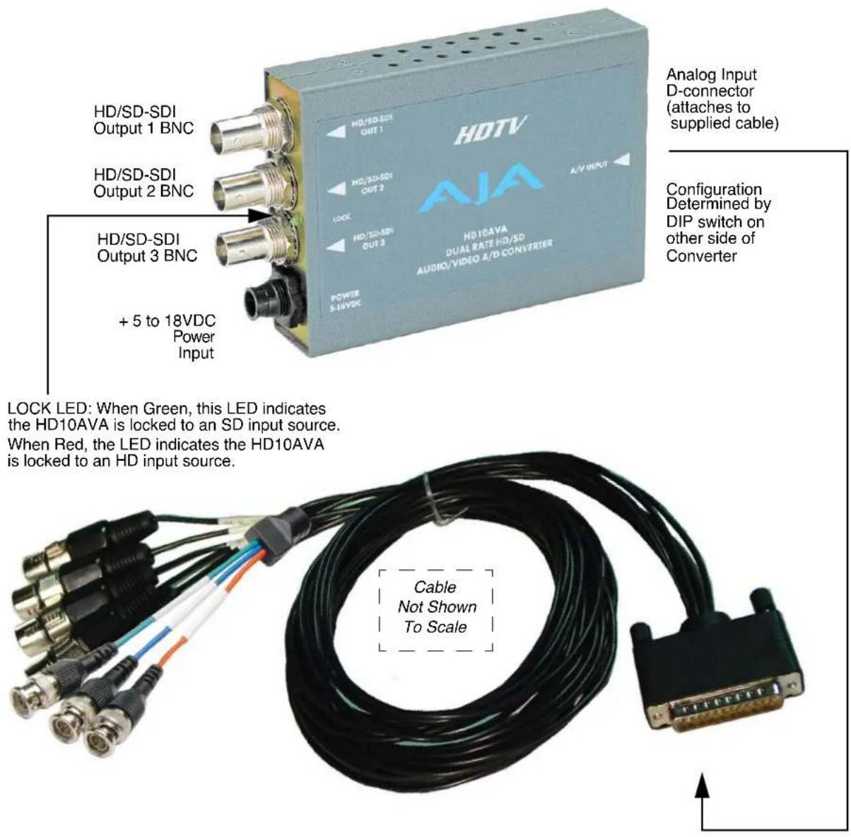
The HD10AVA is a miniature, high-quality, audio/video, HD/SD A/D converter. The HD10AVA automatically detects the video input format and embeds the audio inputs in the SDI/HD-SDI outputs. The HD10AVA is useful for adding an SDI/HD-SDI audio/video output to tape decks or any professional video equipment with analog outputs. The HD10AVA is especially useful for adding HD-SDI outputs to most HDV cameras or decks by using the component outputs of such devices. The HD10AVA uses a breakout cable for audio/video inputs and provides 3 SDI-HD-SDI on BNCs.
Features
• High-Quality SD/HD Audio/Video A/D Converter
• SD Component, Composite or Y/C Video Input
• HD Analog Component Video Input
• Four Channel Balanced Analog Audio Input
• 3 SDI/HD-SDI w/embedded Audio Outputs
• 12 Bit Video, 24 Bit Audio A/Ds
• Automatic Multi-Standard
• External Dip Switch Configuration
- LOCK LED indicates type of input source (SD-Green or HD-Red)
- 5-18V Power
Video SD Input Modes Supported
• 525i 29.97 and 625i 25
HD Input Modes Supported
• 1080p component 23.98psf/24psf
• 1080i component 50/59.94/60
• 720p component 50/59.94/60
Audio
The HD10AVA supports 4 analog audio input channels (2 stereo pairs) at 48 KHz. These inputs are connected via a supplied cable that attaches to a D-connector on the converter. Connections are made via high quality XLRs.
Block Diagram

flowchart
graph TD
    A["Audio in1"] --> B["Audio ADC Channel 1&2"]
    C["Audio in2"] --> B
    D["Audio in3"] --> E["Audio ADC Channel 3&4"]
    F["Audio in4"] --> E
    G["Composite, S-Video, Component"] --> H["Video ADC"]
    H --> I["Dejitter"]
    I --> J["Embed Audio"]
    J --> K["Serializer"]
    K --> L["Line Drivers"]
    M["Embedder Control"] --> N["Audio Process"]
    O["Analog Input Connectors"] --> H
    P["SDI_out1"] --> J
    Q["SDI_out2"] --> J
    R["SDI_out3"] --> J
I/O Connections
text_image
HD/SD-SDI Output 1 BNC HD/SD-SDI Output 2 BNC HD/SD-SDI Output 3 BNC + 5 to 18VDC Power S-18VDC HDTV AJA HDTVAVA DUAL RATE HD/SD AUDIO/VIDEO A/D CONVERTER Analog Input D-connector (attaches to supplied cable) Configuration Determined by DIP switch on other side of Converter LOCK LED: When Green, this LED indicates the HD10AVA is locked to an SD input source. When Red, the LED indicates the HD10AVA is locked to an HD input source. Cable Not Shown To ScaleHD10AVA and Cable, Side View
User Controls
DIP Switch Setting
LEFT RIGHT
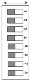
COMP SD VIDEO CMPST
OFF S VIDEO ON
ON PEDESTAL OFF
PRO AUDIO LVL CSMR
HI AUDIO LVL LOW
ON AUDIO EMBD OFF
OFF AUX ON
OFF AUX
MODEL HD10AVA

USA
Tel 530-274-2048
www.aja.com
The user interface for the HD10AVA is an 8-switch DIP accessible through a cut-out in the bottom of the unit. Use the DIP switches to configure functions, formats and levels.
Note: The combination of switch settings determines the overall operation of the HD10AVA.
The exact purpose of each DIP switch and what it controls is described on the following pages.
Switch 1 (SD VIDEO)—Selects Component or Composite Analog Input for Standard Definition
| LEFT (COMP) RIGHT (CMPST) | |
| Selects SD Component Analog Input | Selects SD Composite Input |
Switch 2 (S VIDEO)—Selects S-Video Input (Switch 1 must be in "CMPST" position to select "S-Video")
| LEFT (OFF) RIGHT (ON) | |
| Input BNC 1 (Green) is Composite | Input BNC 1 (Green) is S-Video “Y”, BNC 2 (Blue) is S-Video “C” |
Switch 3 (PEDESTAL)—Configures Pedestal Processing (Also Configures SD Component for SMPTE/BETA)
| LEFT (ON) RIGHT (OFF) | |
| Pedestal is present in input video; also configures SD component for BETA | Pedestal is not present in input video; also configures SD component for SMPTE |
Note: Switches 1 through 3 do not affect HD. HD inputs must be YPbPr.
Format Selection Matrix For Switches 1, 2, 3 and 7
The following table shows the combinations of DIP switch settings required to configure various formats.
| Format DIP Switch #1COMP-CMPST | DIP Switch #2S-VIDEO | DIP Switch #3PEDESTAL | DIP Switch #7NTSC-J | |
| SD NTSC Composite | RIGHT LEFT LEFT LEFT | |||
| SD NTSC S-Video | RIGHT RIGHT LEFT LEFT | |||
| SD NTSC/PAL/NTSC-J Component-SMPTE/N10 | LEFT n/a RIGHT LEFT | |||
| SD NTSC Component-BETA | LEFT n/a LEFT LEFT | |||
| SD PAL Composite | RIGHT LEFT n/a n/a | |||
| SD PAL S-Video | RIGHT RIGHT n/a n/a | |||
| SD NTSC-J Composite | RIGHT LEFT n/a RIGHT | |||
| SD NTSC-J S-Video | RIGHT RIGHT n/a RIGHT | |||
| SD NTSC-J Component - BETA | LEFT n/a | n/a RIGHT | ||
Note: HD formats are auto-detected and configured for YPbPr component.
Switch 4 (AUDIO LVL)—Selects Whether Audio Input Levels are Professional Or Consumer. Affects all 4 Inputs.
| LEFT (PRO) | RIGHT (CSMR) |
| Professional Levels.(See Level Selection Matrix Table) | Consumer Levels.(See Level Selection Matrix Table) |
Note: Professional audio equipment uses much higher levels than consumer equipment: nominal professional levels are +4/-6dBu, consumer levels are -8/-14dBu.
Switch 5 (AUDIO LVL)—Control Whether Audio Levels are High or Low. Affects all 4 Inputs.
| LEFT (HIGH) | RIGHT (LOW) |
| High Level(See Level Selection Matrix Table) | Low Level(See Level Selection Matrix Table) |
Input Level Selection Matrix For Switches 4 and 5
The following table shows the combinations of DIP switch settings required to configure the audio input levels shown.
| Input Level Range Full Scale(0dBFS) | DIP Switch#4 | DIP Switch#5 | |
| Professional US | +24dBu LEFT | LEFT | |
| Professional European | +18dBu LEFT | RIGHT | |
| Consumer High (IHF) | +12dBu RIGHT | LEFT | |
| Consumer Low | +15dBu RIGHT | RIGHT | |
Switch 6 (AUDIO EMBED)—Turns SDI audio embedding ON or OFF.
| LEFT (ON) RIGHT (OFF) | |
| ON converts and embeds the input audio into the digital SDI outputs | OFF turns audio embedding off; input audio is not supplied with the SDI outputs. |
Switch 7 (AUX)—Switches Input Levels to NTSC-J
| LEFT (OFF) RIGHT (ON) | |
| Normal operation (NTSC levels) | NTSC-J levels for Composite, S-Video, and BETA inputs |
Switch 8 (AUX)—Controls Wide/Narrow blanking for SD formats; it does not apply to HD formats
The operation of switch 8 is independent of all other switches. It affects the output of SD video during vertical blanking lines.
| LEFT (OFF) RIGHT (ON) | |
| All data during vertical blanking is replaced with black (Y = 0x40, C = 0x200)Only active lines are digitized. | If input video is NTSC, HD10AVA also digitizes the luminance data present on lines 10-20 and lines 272-283, in addition to normal active video lines.If input video is PAL, HD10AVA also digitizes the luminance data present on lines 6-22 and lines 318-335 in addition to normal active video lines. |
Installation
Typically, HD10AVA installation consists of the following:
- configure the DIP switch for the desired equipment configuration and video/audio formats—power to the converter may be on or off when this is done (the converter will respond to DIP switch changes at the time they are made so power cycling is not necessary)
- ensure video/audio equipment is properly connected to the converter—check all converter BNC and XLR connections
- ensure the converter has a proper power supply source: +5 to +18VDC power (we recommend AJA power supply model DWP)
Specifications
| Item Specification | |
| Formats 1080i 50/59.94/60 Hz | 1080psf 23.98/24 Hz1035i 50/59.94/60 Hz720p 50/59.94/60 Hz |
| Video Inputs HD component YPbPr, (SMPTE-274), 3 BNCSD component/composite/YC (S Video), 3 BNC | |
| Video Outputs SDI, HD-SDI, SMPTE-259/292/296, 3 BNC | |
| Audio Inputs 4 Channel Balanced, 4 XLR | |
| Video A/D 12 bits | |
| Audio A/D 24 Bits, 48Khz | |
| Audio levels +12dBu, +15dBu, +18dBu, +24dBu, Full Scale Digital | |
| User Controls External Dipswitch: | Component/Composite (SD)Composite/YC (SD)Pedestal Present (on/off) (SD)Audio Input LevelEmbed Audio on/off |
| Size 5.8" x 3.1" x 1 (147 x 79 x 25mm) | |
| Power 5-18V, 5 watts. Requires power supply. | |