
GLXD24R - Uncategorized SHURE - Free user manual and instructions
Find the device manual for free GLXD24R SHURE in PDF.


| Product Type | Advanced Digital Wireless Receiver |
| Model | GLXD4R (GLXD24R variant) |
| Brand | Shure |
| Dimensions (H x W x D) | 42 x 197 x 163 mm (1.7 x 7.8 x 6.4 in) |
| Weight | 907.2 g (32 oz) without batteries |
| Power Supply | 14 to 18 V DC, 550 mA (included power supply) |
| Audio Outputs | XLR (balanced) and 1/4" TRS (impedance balanced) |
| Frequency Range | 2400-2483.5 MHz (2.4 GHz ISM band) |
| Working Range | Up to 30 m (100 ft) indoors, up to 60 m (200 ft) outdoors |
| Audio Frequency Response | 20 Hz - 20 kHz |
| Dynamic Range | 120 dB, A-weighted |
| Total Harmonic Distortion | 0.2% typical |
| Battery Life (Transmitter) | Up to 16 hours with SB902 Li-Ion battery |
| Charging Time | From AC: 3 hours for full charge; from USB: longer |
| Gain Adjustment Range | -18 to +42 dB in 1 dB steps |
| Antenna Type | 1/2 wave sleeve dipole (two per receiver) |
| Operating Temperature | -18°C to 57°C (0°F to 135°F) |
| Storage Temperature | -29°C to 74°C (-20°F to 165°F) |
| Housing Material | Steel (receiver), cast metal or plastic (transmitters) |
| Maintenance | Clean with dry cloth only; avoid moisture and heat |
| Safety Compliance | FCC Part 15, IC RSS-247/RSS-GEN, CE, RoHS, WEEE |
| Accessories Included | Power supply, antennas, rack-mount kit, battery, USB cable |
Frequently Asked Questions - GLXD24R SHURE
User questions about GLXD24R SHURE
0 question about this device. Answer the ones you know or ask your own.
Ask a new question about this device
Download the instructions for your Uncategorized in PDF format for free! Find your manual GLXD24R - SHURE and take your electronic device back in hand. On this page are published all the documents necessary for the use of your device. GLXD24R by SHURE.
USER MANUAL GLXD24R SHURE
IMPORTANT SAFETY INSTRUCTIONS
-
READ these instructions.
-
KEEP these instructions.
-
HEED all warnings.
-
FOLLOW all instructions.
-
DO NOT use this apparatus near water.
-
CLEAN ONLY with dry cloth.
-
DO NOT block any ventilation openings. Allow sufficient distances for adequate ventilation and install in accordance with the manufacturer's instructions.
- Do not reduce the risk of fire or electric shock, do not expose to rain or moisture.
-
Do not attempt to modify this product. Doing so could result in the use of the product that fails to
-
DO NOT install near any heat sources such as open flames, radiators, heat registers, stoves, or other apparatus (including amplifiers) that produce heat. Do not place any open flame sources on the product.
-
DO NOT defeat the safety purpose of the polarized or grounding type plug. A polarized plug has two blades with one wider than the other. Caution: risk of electric shock grounding type plug has two blades and a third grounding prong. The wider blade or the third prong are provided for your safety. If the provided plug does not fit into your outlet, consult an electrician for replacement. Caution: risk of danger (See note.) of the obsolete outlet.
-
PROTECT the power cord from being walked on or pinched, particularly at plugs, convenience receptacles, and the point where they exit from Alternating current the apparatus. On (Supply)
-
ONLY USE attachments/accessories specified by the manufacturer.
-
USE only with a cart, stand, tripod, bracket, or table specified manufacturer, or sold with the apparatus. When a cart is used, when moving the cart/apparatus combination to avoid injury from

-
DO NOT expose the apparatus to dripping and splashing. DO objects filled with liquids, such as vases, on the apparatus.
-
The MAINS plug or an appliance coupler shall remain readily
-
The airborne noise of the Apparatus does not exceed 70dB (
-
Apparatus with CLASS I construction shall be connected to a socket outlet with a protective earthing connection.
-
To reduce the risk of fire or electric shock, do not expose to rain or moisture.
-
Do not attempt to modify this product. Doing so could result in injury and/or product failure.
-
pro Operate this product within its specified operating temperature r uct.
Explanation of Symbols
e other. Caution: risk of electric shock ng. 7 The the provided placement Caution: risk of danger (See note.)
Direct current particularly from Alternating cu
On (Supply)
Use cell Equipment protected throughout by DOUBLE INSULATION or reinforced REINFORCED INSULATION
Equipment should not be disposed of in the normal waste
-
UNPLUG this apparatus during lightning storms or when unused for long periods of time.
-
REFER all servicing to qualified service personnel. Servicing is WARNING: Voltages in this equipment are hazardous to life. No use when the apparatus has been damaged in any way, such as possible parts inside. Refer all servicing to qualified service personnel supply cord or plug is damaged, liquid has been spilled or objects have fallen into the apparatus, the apparatus has been exposed to the factory setting. moisture, does not operate normally, or has been dropped.
WARNING: Battery packs shall not be exposed to excessive heat such. Does not charge or use battery packs with other than specified \$ sunshine, fire, or the like. products
WARNING: Danger of explosion if incorrect battery replaced. Operate only dispose of battery packs properly. Check with local vendor for with AA batteries. disposal of used battery packs
WARNING: This product contains a chemical known to the State of California to cause cancer and birth defects or other reproductive harm. Note:
WARNING
- Battery packs may explode or release toxic materials. Risk of fire burns. Do not open, crush, modify, disassemble, heat above 140° (60°C), or incinerate
• Follow instructions from manufacturer
- Never put batteries in mouth. If swallowed, contact your physician of local changes or modifications not expressly approved by Shure Incorporation control center poison control center could void your authority to operate this equipment.
- Do not short circuit; may cause burns or catch fire
California Note:
• This equipment is intended to be used in professional audio app
- EMC conformance is based on the use of supplied and recommend cable types. The use of other cable types may degrade EMC maintenance.
Use this battery charger only with the Shure charging modules and packs for which it is designed. Use with other than the specif and battery packs may increase the risk of fire or explosion.
Changes or modifications not expressly approved by Shure Incorpor could void your authority to operate this equipment.
Note: Use only with the included power supply or a Shure-approved equivalent.
System Overview
GLX-D Advanced Digital Wireless Systems combine Automatic Frequency Operates in globally unlicensed 2.4 GHz spectrum Management technology with a rack mountable metal receiver, rechargeable lithium-ion batteries, world-renowned microphones, and unparalleled design and construction. New GLX-D Advanced Frequency Managers (available separately) connect multiple GLXD4R receiver systems for increased channel half-rack size and metal chassis count and improved RF reliability, consolidating RF to one pair of antennas. New antenna accessories help improve reception by letting you mount an lifetime as closer to transmitters, with directional reception for improved performance. Available in a variety of bodypack and handheld configurations, GLX-D Advanced Digital Wireless sets the standard for ease of operation and automatically moves away from interference without audio interruption.
Features
• Exceptional digital audio clarity
Furnished Accessories
| 95A32436Reverse | SMA Bullead in AcperswithlockG1XD24, out G12XD24 systems. | |
| UA802-RSMA0.6 m (2 ft.) Reverse SMA Cable (2) | ||
| PS43Power Supply | ||
| 95B13528UA8-2.4 | GHz 1/2 Wave Antenna (2) | |
| 90AZ8100Rack-mounting hardware kit | ||
| SB902Shure Lithium-Ion Rechargeable Battery* | ||
| 95A21651USB Cable, Type A to Micro-B* | ||
Optional Accessories
| UA846Z2-LCGLX-D Frequency Manager | UA806-RSMA1.8 m (6 | |||
| PA805Z2-RSMAPassive | 7.6 m (25 ft.) Reverse SMA Cable Directional Antenna 2.4 GHz | UA825-RSMA | ||
| Reverse SMA Passive Antenna Splitter (900 MHz ISM, DECT, 2.4 GHz) | UA221-RSMA | 15.2 m (50 ft.) Reverse SMA Cable | UA850-RSMA | |
| 30.4 m (100 ft.) Reverse SMA Cable | UA8100-RSMA | |||
| UA505-RSMAWall Mount for PA805Z2-RSMA Burkhead Adapters | 95A32436 | |||
| UA8-2.4GHZ1/2 Wave m (2 | Antenna, 45 deg. (2.4 GHz) | SBC10-902Stand Alone | ||
| UA802-RSMA0.6 | ft.) Reverse SMA Cable Charger | SBC-CAR | ||
Quick Start for Single Receiver
To reduce set-up time, the transmitter and receiver automatically link to form an audio channel the first time they are powered on and never have to be linked again.
Step ①
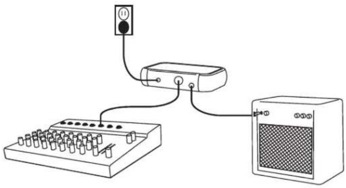
Connect power supply to the receiver and plug cord into an AC power source. Connect the audio output to an amplifier or mixer.
natural_image
Simple line drawing of an audio equipment setup with a switch, power outlet, and speaker (no text or symbols)Step ②
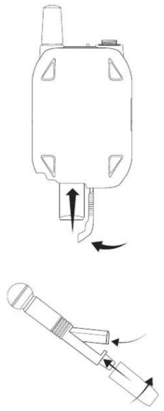
Install charged transmitter batteries.
natural_image
Technical line drawing of a mechanical component with directional arrows indicating motion (no text or symbols)Step ③
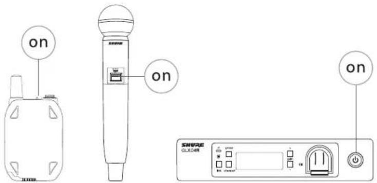
Turn on the transmitter and receiver. The blue rf LED will flash while the transmitter and receiver form a link. The rf LED turns solid blue when the link has successfully formed.
Note: The transmitter and receiver will remain linked for future usage. At power-up, the blue rf LED and transmitter LED will illuminate, skipping the linking step.
Step ④
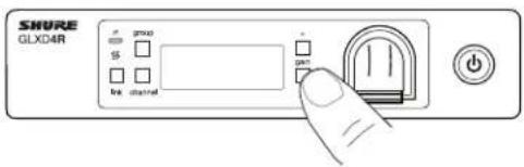
Check the audio and adjust the gain if necessary.
Receiver Controls and Connectors
Front Panel
Rear Panel
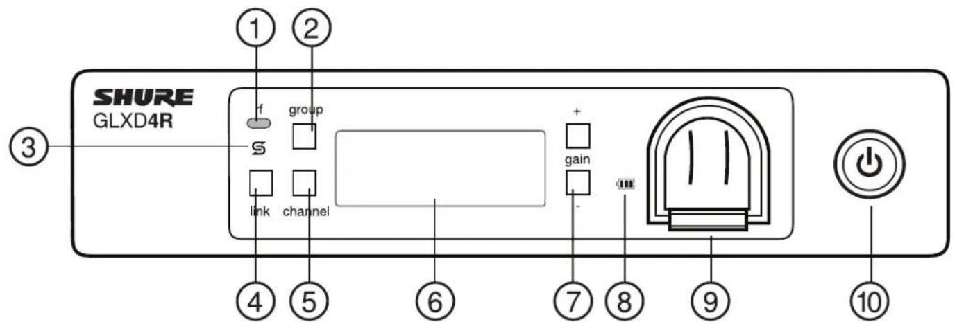
① RF Status LED
• ON = Linked transmitter is on.
- Flashing = Searching for transmitter.
• OFF = Linked transmitter off or transmitter unlinked.
② Group Button
Press and hold for two seconds to enable manual group edit.
③ Data Sync LED
- ON = Data sync is on (receiver connected to GLX-D Frequency Manager).
- Flashing = Searching for frequencies.
• OFF = Data sync is off (receiver not connected to GLX-D Frequency Manager).
④ Link Button
Press to manually link receiver to a transmitter or to activate the remote ID function.
⑤ Channel
- Press to start a channel scan.
- Press and hold for two seconds to enable manual channel edit.
⑥ LCD Screen
Displays receiver and transmitter status.
⑦ Gain Buttons
Press to increase or decrease transmitter gain in 1 dB increments.
⑧ Battery Charging Indicator
Illuminates when battery is in charging bay:
• Red = Battery charging.
• Green Flashing = Battery charge at 90%.
• Green = Battery charged.
- Amber Flashing = Charging error, replace battery.
⑨ Battery Charging Bay
Charges transmitter battery if receiver is plugged in to power outlet.
⑩ Power Button
Powers the unit on and off.
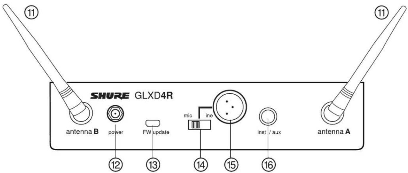
⑪ Antenna
Two antennas per receiver. Antennas pick up the signal from the transmitter.
⑫ Power Supply Jack
Connect the supplied 15 V DC external power supply.
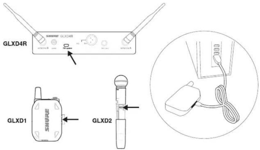
⑬ Firmware Update
Connect to computer to download firmware updates.
⑭ Mic/Line Switch
Sets XLR output level to microphone or line level.
⑮ XLR Audio Output
Supplies microphone-level or line-level audio output.
⑯ Inst/Aux Out
TRS 1/4" (6.35mm) audio output. Connect to mixers, recorders, and amplifiers.
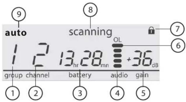
Receiver Screen
① Group
Displays the selected group.
② Channel
Displays the selected channel.
③ Transmitter Battery Runtime
Displays remaining battery life in hours and minutes.
Alternatively displays the following battery status:
• CALC = battery life calculation
• Lo = battery life less than 15 minutes
- Err = replace battery
④ Audio Meter
Indicates audio signal level and peaks.
⑤ Gain
Displays transmitter gain settings (dB).
⑥ OL Indicator
Indicates audio overload, reduce gain.
⑦ Transmitter Locked
Displayed when linked transmitter controls are locked.
⑧ Scanning
Indicates a scan is in progress.
⑨ Auto
Indicates that the selected group has backup channels available.
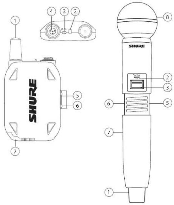
Transmitters
① Antenna
Carries wireless signal.
② Status LED
LED color and state indicate transmitter status.
③ Power Switch
Turns the transmitter on/off.
④ TA4M Input Jack
Connects to a 4-Pin mini connector (TA4F) microphone or instrument for cablest results, the belt should be pressed against the base of
⑤ Micro USB Charging Port
Connect to USB battery charger.
⑥ Link Button
- Press and hold within 5 seconds of power-on to manually link with receiver - Press momentarily to activate Remote ID function
⑦ Battery Compartment
Holds 1 Shure rechargeable battery.
⑧ Microphone Cartridge
GLXD-2 transmitter models are available with the following cartridge types: SM58, Beta 58, SM86, Beta 87A.
Transmitter Status LED
LED is green during normal operation.
LED color or flashing indicates a change in transmitter status as shown in the following table:
| StatusStateColor | ||
| Green | transmitter attempting relink with receiverFlas | |
| unlinked transmitter searching for receiverFlas | ||
| Flashes 3 times | indicates locked transmitter when power switch is pressed | |
| Red | battery life < 1 hourOn | |
| battery life < 30 minutesFlashing | ||
| remote ID activeFlashingRed/Green | ||
| battery error, replaser batteryFlashing |
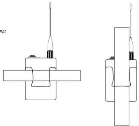
Wearing the Bodypack Transmitter
Clip the transmitter to a belt or slide a guitar strap through the as shown.
natural_image
Technical line drawings of two mechanical components with no visible text or symbolsWearing the Headworn Microphone
- Position the headworn microphone 13 mm (1/2 in.) from the cor your mouth.
- Position lavalier and headworn microphones so that clothing, jewel other items do not bump or rub against the microphone.
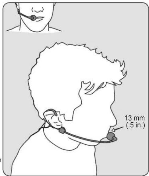
Correct (slow) Microphone Placement
ceiverFlashHood (fast) microphone within 12 inches from the sound source.
- For a warmer sound with increased bass presence, move the mi closer to the sound source.
- Do not cover grille with hand.
Batteries and Charging
GLX-D transmitters are powered by Shure SB902 lithium-ion rechargeable batteries. Advanced battery chemistry maximizes runtimes with zero mChargi
effects, eliminating the need to discharge batteries prior to charging.1. Plug the
When not in use, recommended battery storage temperature is 10^ C. (500°F) the to 25^ C (77°F).
Note: The transmitter will not pass RF or audio signals when connected to the charging cable.
The following battery charging options are available:
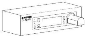
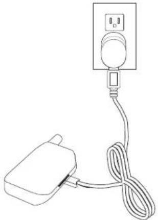
Receiver Charging Bay
The receiver's built-in charging bay will charge transmitter batteries when receiver is plugged in to power outlet.
- Insert the battery into the charging bay.
- Monitor the battery charging indicator on the front panel.
natural_image
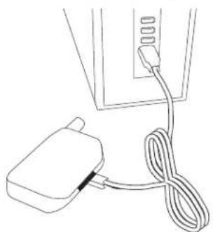
Line drawing of a plug connected to a power outlet with coiled cable (no text or symbols)Charging from a USB Port
- Plug the USB charging cable into the charging port on the tra
- Plug the cable into a standard USB port.
natural_image
Line drawing of a plug connected to a cable with a connector (no text or symbols)LED Status During Charging
The following LED states indicate battery status when the transmitter connected to a charger:
er iGreen = charging complete
- Green Flashing = battery charge > 90%
• Red = battery charging - Amber Flashing = battery error, replace battery
Installing Transmitter Batteries
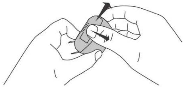
Bodypack Transmitter
- Move the locking lever to the open position and slide the battery door open.
- Place the battery into the transmitter.
- Close the battery door and slide the latch to lock.
natural_image
Illustration of two hands holding a small object with an arrow indicating direction (no text or symbols)Handheld Transmitter
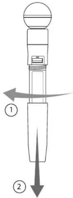
- Unscrew and remove the battery cover.
- Place the battery into the transmitter.
- Replace and tighten the battery cover.
Charging Times and Transmitter Runtimes
Use the following table to determine approximate battery runtime the duration of charging time. Times shown are in hours and m D transmitters automatically power-off after approximately 1 hour to battery life if the signal from a linked receiver is not detected.
| Receiver Bay or ACUSB Connection Power Source Charging Charging | Transmitter | Runtime | |
| up to 1:300:300:15 | |||
| up to 3:001:000:30 | |||
| up to 6:002:001:00 | |||
| up to 16:00*4:003:00 | |||
*Storage time or excessive heat will reduce maximum runtime.
Note: If receiver is powered off and remains plugged in, battery will continue charging.
Important Tips for Care and Storage of Shure Rechargeable Batteries
Proper care and storage of Shure batteries results in reliable performedally, batteries should be charged to approximately 40% of cap and ensures a long lifetime. for long-term storage
• Always store batteries and transmitters at room temperature
- During storage, check batteries every 6 months and recharge to capacity as needed
2.4 GHz Spectrum Overview
GLX-D operates within the 2.4GHz ISM band which is utilized by Wi-Fi.
Bluetooth, and other wireless devices. The benefit of 2.4GHz is
global band that can be used anywhere in the world, license
Overcoming the Challenges of 2.4 GHz
free. The challenge of 2.4 GHz is that Wi-Fi traffic can be unpredictable meets these challenges in the following ways:
- Prioritizes and transmits on the best three frequencies per channel (choosing from a pool of six frequencies across the 2.4 GHz
- Seamlessly moves away from interference to backup frequencies audio interruption
- Optional GLX-D Frequency Manager improves RF reliability for with more than two receivers
- Continuously scans during usage to rank all frequencies (both and backup frequencies)
- Antenna mounting accessories and directional antennas (available arately) help reduce transmitter-to-antenna distance and connect tenna splitter
Coexisting with Wi-Fi
If you plan to use Wi-Fi during a performance, turn on Wi-Fi devices prior to turning on GLX-D and scanning for the best channel. GLX-D detects and avoids other Wi-Fi traffic by scanning the entire 2.4 GHz environment and selecting the three best frequencies to transmit on. This method avoids with a strong Wi-Fi presence
Fi signals and results in reliable performance for your GLX-D wireless 24 GHz systems from other manufacturers in use
"Bursting" Wi-Fi is harder to detect as it is periodic; however, because GLX-
D only repeats the most important information, even bursts at very high levels. Unlike analog TV band wireless system which typically uses type of transmissions across manufacturers, all 2.4 GHz wireless copper on the market use different variations of wireless transmission. These encences make it more difficult to mix and match 2.4 GHz systems manufacturers, as can be done with TV band wireless solutions.
with Challenging Wireless Environments
Some environments are more difficult than others for 2.4 GHz wireless systems performance. Additionally, body absorption has a greater impact in t GHz spectrum compared to the UHF spectrum. The simplest solution current is to reduce transmitter-to-receiver distance by placing receiver the stage with a clear line of sight. You can also mount antenna using Shure directional antennas to reduce transmitter-to-antenna distance to an challenging environments include:
- Areas with few reflective surfaces such as:
- Outdoors
Buildings with very high ceilings
s prior to three or
and of more GL
Frequency Manager
AreWi- with a strong Wi-Fi presence
system GHz systems from other manufacturers in use
Tips to Improve Wireless System Performance
If you encounter interference or dropouts, try the following suggestions:
-
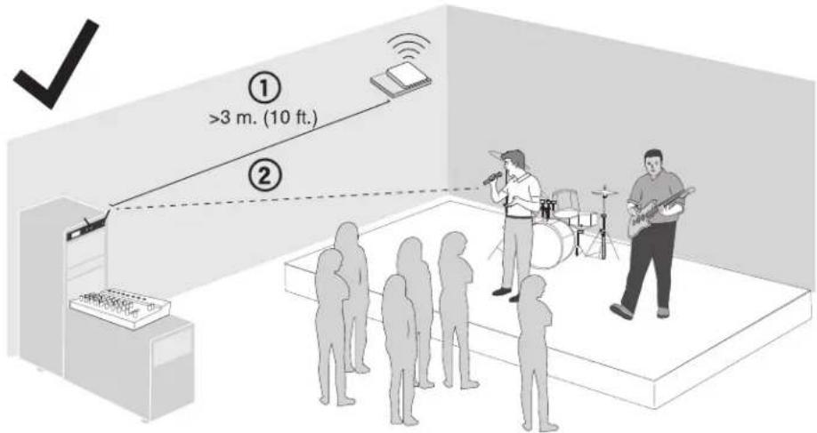
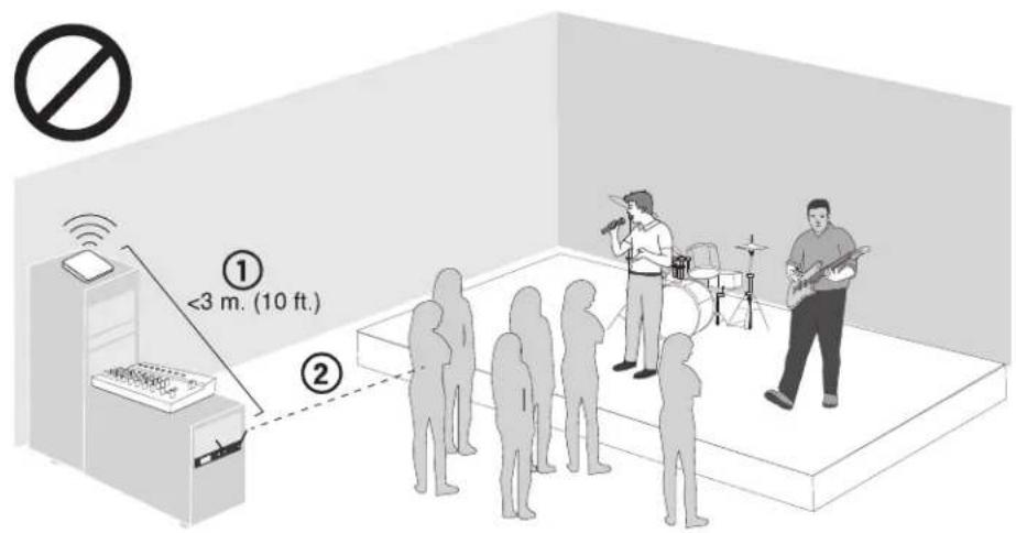
Place receiver at least 3 meters (10 feet) away from Wi-Fi access points, computers, or other active 2.4 GHz sources.
-
Avoid heavy Wi-Fi traffic activities such as downloading large files or viewing a movie.
-
Turn on any Wi-Fi prior to turning on GLX-D and scanning for the best channel.
-
Reduce transmitter-to-receiver distance by placing receivers on stage or above the audience with a clear line of sight to the transmitter.
-
Move receiver to the top of the equipment rack for a clear line of sight.
- Mount antennas remotely to place closer to transmitters and improve RF reliability if receivers cannot be moved closer.
- Make sure people do not block the line of sight between receiver and transmitter.
Additional Tips
- Do not place competitive 2.4 GHz receivers near GLXD4R receivers.
- Connect more than two GLXD4R receivers to a GLX-D Frequency Manager to improve RF reliability.
- Scan for the best available channel by pressing the channel button.
- Keep transmitters more than 2 meters (6 feet) apart. This is less critical with shorter receiver-to-transmitter distances or if receivers are connected to a GLX-D Frequency Manager.
Note: If transmitters are within 6 inches of non-GLX-D transmitters or microphone cartridges, audible noise is possible.
- Move transmitter and receiver away from metal or other dense materials.
- During sound check, mark trouble spots and ask performers to avoid those areas.
-
If there is a strong source of Wi-Fi and you specifically want to use frequencies within that Wi-Fi channel, use the following Group/Channel combinations (best option listed first):
-
Wi-Fi 1: Group 3/Channel 8, Group 3/Channel 4
- Wi-Fi 6: Group 3/Channel 7, Group 3/Channel 5
- Wi-Fi 11: Group 3/Channel 2, Group 3/Channel 1
Remote Antenna Placement
Follow these guidelines when mounting antennas remotely:
- Reduce distance between transmitter and antenna.
- Mount antennas farther from each other to improve performance.
- Position antennas so there is nothing obstructing the line of sight transmitter, including the audience.
-
Keep antennas away from metal objects and any other antennas.
-
Use only low-loss reverse SMA cable to avoid poor RF signal.
- Consult cable's specifications and calculate signal loss for desirable cable run.
Use one continuous length of cable from the antenna to the re to the increase signal reliability.
Always perform a walk-around test to verify coverage before using wireless system during a speech or performance. Experiment with na placement to find the optimum location. If necessary, mark a spots and ask presenters or performers to avoid those areas.
Multiple Receiver Systems
To run more than two receivers at the same time, the GLX-D Frequency Manager is recommended to improve RF reliability.
However, you can run multiple receivers without the frequency manager. Select the group by determining the total number of receivers in your system (channel count). All receivers in the system must be set to the same group.
| Group | Channel Count (Number Receivers) | of Number of Backup Frequencies Per Channel | Notes |
| Initial factory setting.3Up to 41 | |||
| 3Up to 5*2 | Best multi-channel group if you experience interference. | ||
| 0Up to 8*3 | Only use Group 3 in controlled Wi-Fi environments because there frequencies to avoid interference. | ||
| 4 | 1 | 27 | Best single-channel group if you experience interference. |
*Environmentally dependent, 4 systems typical
See "Tips to Improve Wireless System Performance" section for additional information. For information about receiver groups when connected to the GLX-D Frequency Manager, see the UA846 user guide.
Setting Up Receivers and Transmitters
Note: Before beginning, turn off all receivers and transmitters. Turn on and set up each receiver/transmitter pair individually to prevent cross-linking.
- Turn on the first receiver.
- Press and hold the group button to select a group (if necessary) or if the group is already set, press the channel button to scan for the best available channel.
- Turn on the first transmitter. The rf LED turns solid blue when a link is established.
Repeat steps 1-3 for each additional receiver and transmitter. Remember to set each receiver to the same group.
See GLX-D Frequency Manager guide for setting up receivers and transmitters when connected to the frequency manager.
Note: Dashes appearing on the group and channel display during a channel scan indicate that frequencies are not available in the selected group. Choose a group that supports more receivers and repeat set-up steps.
Manually Linking a Transmitter to a Receiver
Use the manual linking option to change the transmitter linked to a receiver and hold the link button on the receiver: The blue rf LED will flash. A common use for manual linking is changing the linked transmitter from then remain on when the link has been established. bodypack type to a handheld type. 3. Test the audio to verify the link and adjust the gain if
-
Turn on the transmitter: Within 5 seconds, press and hold the LINK button until the transmitter LED begins to flash green.
-
Test the audio to verify the link and adjust the gain if neces
Combo Systems
A combo system is created by linking two transmitters to a single1.receiver. the group button to select a group. The receiver automatic Only one transmitter can be active at a time to prevent cross interference. the selected group to find the best available channel. Gain settings for each transmitter can be independently set and stored when the transmitter is active. 2. Turn on transmitter 1 and link it to the receiver. Adjust the gain
Important! Do not turn on and operate both linked transmitters at any time.
Turn off both transmitters before beginning.
- Turn on transmitter 2 and link it to the receiver. Adjust the g turn off the transmitter.
Note: A transmitter can only link to one GLX-D receiver at a time
Operation
Gain Adjustment
Use the gain buttons on the receiver to increase or decrease the linked transmitter:
- Turn on the linked transmitter and momentarily press the gain buttons to adjust the gain in 1 dB increments
- For faster gain adjustments, press and hold the gain buttons
- To replicate the output level of a guitar, unity gain is -18 dB output
Tip: Monitor the audio and observe the receiver audio meter level while adjusting the gain to prevent signal overload.

for the 14 " Locking and Unlocking the Controls
The controls of the receiver and transmitter can be locked to prev tal or unauthorized changes to settings.
Note: Locks are not affected by power cycles.
Locking the Receiver Controls
Simultaneously press and hold the group and channel buttons until pears on the LCD. Repeat to unlock.
- LK is displayed if a locked control is pressed
- UN is displayed momentarily to confirm the unlock command
Locking the Transmitter Power Switch
Starting with the transmitter set to off, press and hold the LINK button while turning on the transmitter. Continue to hold the link button until appears on the receiver LCD. Repeat sequence to unlock.
- To exit Remote ID mode, momentarily press the link button or allow the function to timeout. LK ap-
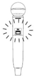
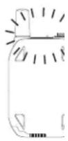

Optionally, the transmitter power switch can be remotely locked ceiver front panel:
Simultaneously press and hold the group and link buttons for approximately 2 seconds until the flashing lock icon appears on the receiver sequence to unlock.
Identifying Linked Transmitters and Receivers Remote ID
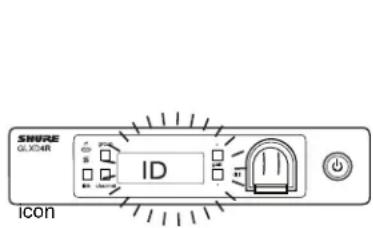
Use the Remote ID feature to identify linked transmitter and receive in multiple receiver systems. When Remote ID is active, the receive will blink and display ID. The status LED of the corresponding to alternately flash red and green for approximately 45 seconds.
To activate Remote ID:
- Momentarily press the link button on the transmitter or receiver.
- The LCD of the linked receiver will blink and display ID and the status LED on the linked transmitter will flash red/green.
Manually Selecting a Group and Channel
Specific groups and channels can be assigned to the receiver instead of the automatic scan function.
Note: Group 3 should only be used in controlled Wi-Fi environments to prevent interference from unexpected Wi-Fi devices.
Selecting a Group
LCD. Repeat
- Press and hold the group button for 2 seconds until the group display flashes.
- Press the group button to scroll through the available groups.
- The receiver will automatically save the selected group.
eiver pairs eiver LCD Selecting a Channel
transmPress and hold the channel button for 2 seconds until the channel display flashes.
- Press the channel button to scroll through the available channels.
- The receiver will automatically save the selected channel.
Note: A double dash symbol -- displayed on the receiver screen during a channel scan indicates that there are no available channels within the group. Choose a group with more channels and repeat set up ste
Firmware
Firmware is embedded software in each component that controls functionality. Periodically, new versions of firmware are developed to incorporate additional features and enhancements. To take advantage of design improvements, new versions of the firmware can be downloaded and installed using the Shure Update Utility tool.
Software is available for download from http://www.shure.com/update-utility.
Connect to the Computer
Connect the device to your computer using the USB to Micro USB cable supplied with your GLX-D system.
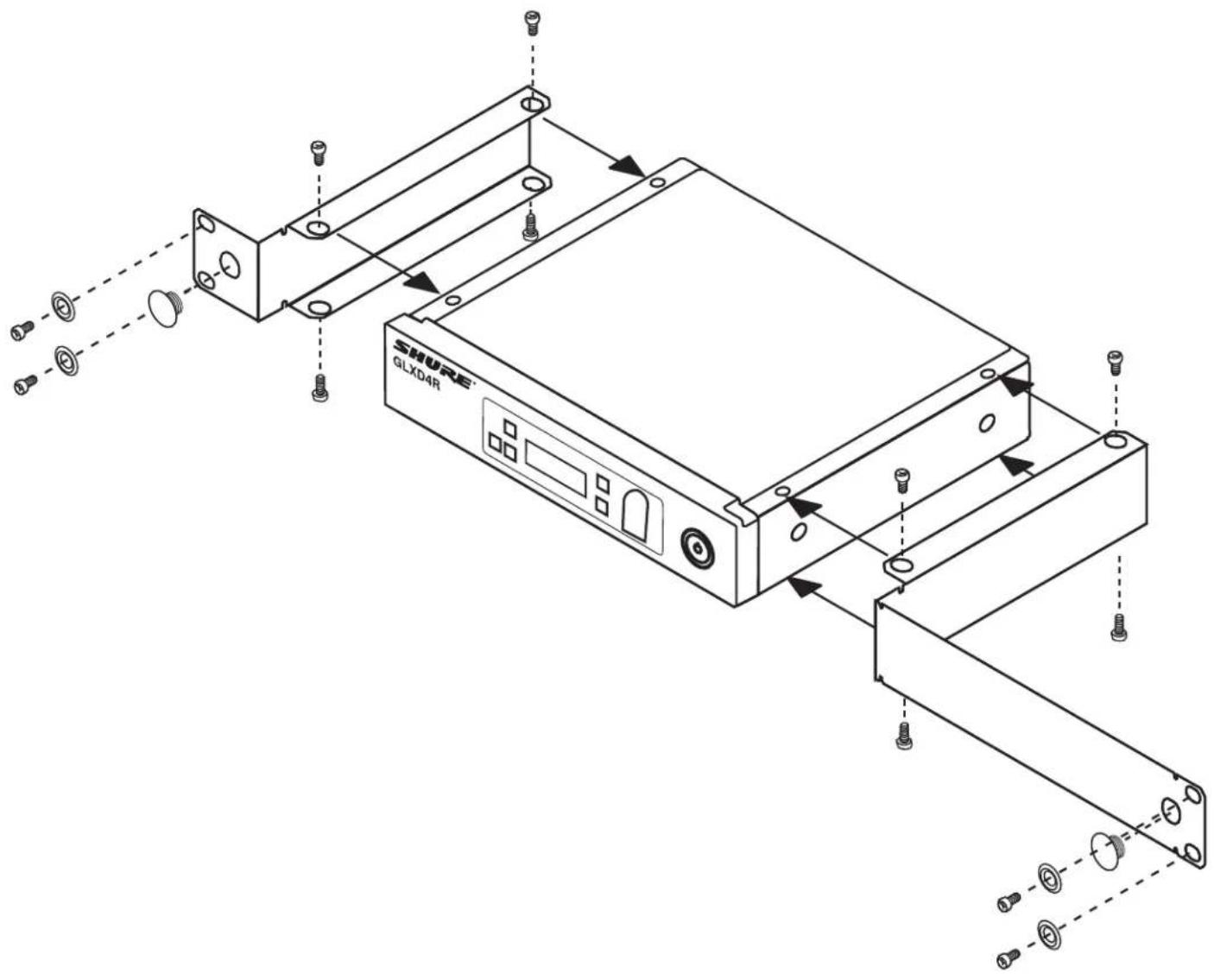
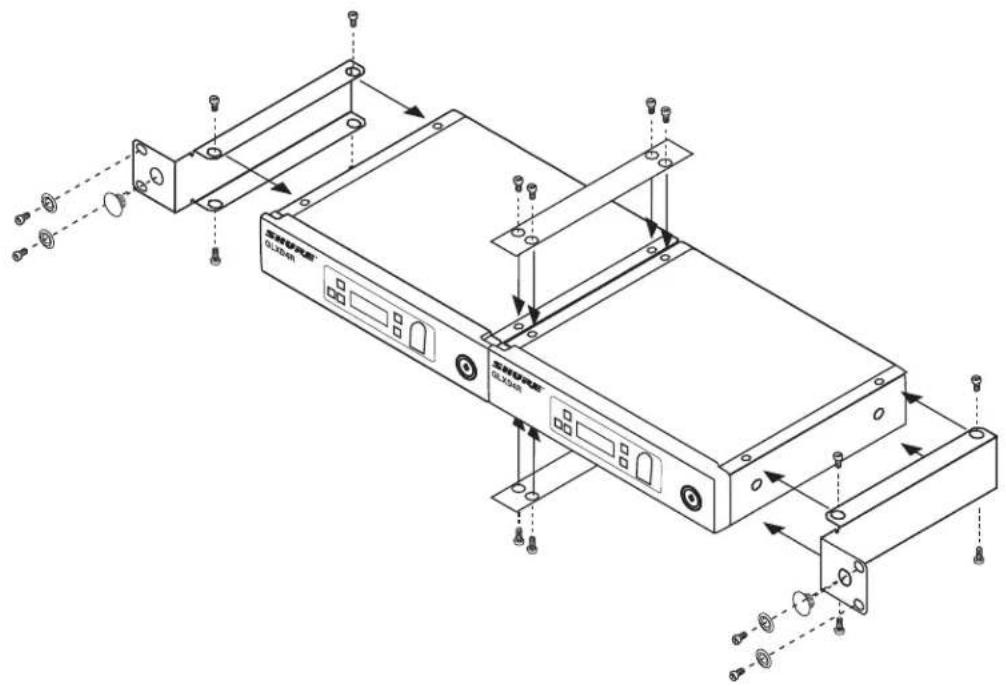
Rack-Mounting Instructions
Use the supplied mounting hardware to install the receiver in a standard 19 inch audio equipment rack.
Troubleshooting
| SolutionIndicator StatusIssue | ||
| No sound or faint sound | Receiver RF LED on | Verify all sound system connections oVerify that the receiver is connected |
| Receiver RF LED off | Turn on transmitter.Make sure the batteries are installedLink transmitter and receiver (see LinCharge or change transmitter battery. | |
| Receiver LCD screen off | Make sure AC adapter is securely pMake sure receiver is powered on. | |
| Transmitter indicator LED flashing red | Charge or change transmitter battery. | |
| Transmitter plugged into charger. | Disconnect transmitter from charger. | |
| Audio artifacts or dropouts | RF LED flickering or off | Change receiver and transmitter to aIdentify nearby sources of interferencecessor, etc.) and shut down or remove source.Charge or change transmitter battery.Ensure that receiver and transmitter aSystem must be set up within recommended range and receiver kept away frommetallic surfaces.Transmitter must be used in line of sight from receiver for optimal sound. |
| Distortion | OL indicator appears on receiver LCD | Reduce transmitter gain (see Gain Adjustment). |
| Transmitter and receiver link unsuccessful | Transmitter and receiver LEDs flash indicate that linking started, but the link fails | Update both components to firmware version 2.0 or greater. Download the Shure Update Utility application and follow the instructions. |
| Sound level variations when switching to different sources | Adjust transmitter gain as necessary (see Gain Adjustment).N/A | |
| Receiver/transmitter won't turn off | Transmitter LED flashing rapidly | Controls locked. See Locking and Unlocking Controls. |
| Check transmitter. Transmitter must be on to enable gain changes.N/A | ||
| Receiver controls cannot be adjusted | LK shown on receiver display when buttons are pressed | Controls locked. See Locking and Unlocking Controls. |
| Transmitter ID function does not respond to response times | Transmitter LED flashes green three times | Controls locked. See Locking and Unlocking Controls. |
| Transmitter information does not appear on the Receiver LCD | Linked transmitter is off or the receiver is not linked to a transmitte | |
| Transmitter powers off after one hour | Transmitter status LED off | LED-LX-D transmitters automatically turn off after one hour to conserve battery signal from a linked receiver is not detected. Make sure that linked receiver |
| Second frequency manager does not RF signal to receivers | send Data sync LED off | Verify that antenna A and antenna B ports on second frequency manager are connected to cascade A and cascade B ports on first frequency manager. |
| RF interference while connected to frequent manager | Receive screen flashes -- -- | Move system away from other 2.4 GHz sources such as Wi-Fi access If using directional antennas, place interference sources behind antennas minimize interference. Place receivers or directional antennas closer to |
Resetting Components
Use the reset function if it is necessary to restore the transmitter to their factory settings.
Resetting the Receiver
Restores the receiver to the following factory settings:
- Gain level = default
- Controls = unlocked
Press and hold the link button while turning on the receiver power until the LCD displays RE.
Note: We are reset is complete, the receiver will automatically initiate linking to search for a transmitter. Press and hold the transmitter link but five seconds of powering-on to complete the link.
Resetting the Transmitter
Restores the transmitter to the following factory settings:
- Controls = unlocked
Press and hold the transmitter link button while turning on the tra until power LED goes off.
When the link button is released, the transmitter will automatically linking to find an available receiver. Press the link button on an ceiver to relink.
Specifications
Tuning Bandwidth
2400-2483.5 MHz
Working Range
| Indoor | Up to 30 m (100 ft) Up to 60 m (200 ft) |
| Outdoor | Up to 20 m (65 ft) to 50 m (165 ft) max |
Transmit Mode
Shure GLX-D proprietary digital
Audio Frequency Response
20 Hz - 20 kHz
Dynamic Range
120 dB, A-weighted
RF Sensitivity
-88 dBm, typical
Total Harmonic Distortion
0.2%, typical
RF Output Power
10 mW E.I.R.P. max
Operating Temperature Range
-18°C (0°F) to 57°C (135°F)
2
Storage Temperature Range
-29°C (-20°F) to 74°C (165°F)
Polarity
Positive pressure on microphone diaphragm (or positive voltage applied to tip of WA302 phone plug) produces positive voltage on pin 2 (with respect to pin 3 of low-impedance output) and the tip of the high impedance 1/4-inch output.
Battery Life
Up to 16 hours
Channel Count
9 typical, 11 maximum
GLXD1
Dimensions
90 x 65 x 23 mm (3.56 x 2.54 x 0.90 in.), H x W x D (with
Weight
132 g (4.7 oz.) without batteries
Power Requirements
3.7 V Rechargeable Li-Ion
Housing
Cast Metal, Black Powdercoat
Input Impedance
900 kΩ
RF Output Power
10 mW E.I.R.P. max
Transmitter Input
Connector
4-Pin male mini connector (TA4M)
Configuration
Unbalanced
Maximum Input Level
1 kHz at 1% THD
+8.4 dBV (7.5 Vp-p)
Antenna Type
Internal Monopole
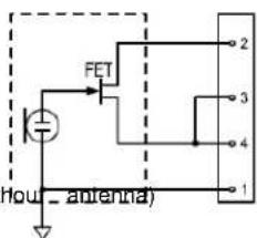
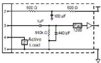
Pin Assignments
TA4M
| ground (cable shield)1 | |
| + 5 V Bias2 | |
| audio3 | |
| 4 | Tied through active load to ground (On instrument adapter cable, pin 4 floats) |
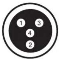
TA4M Connector

GLXD2
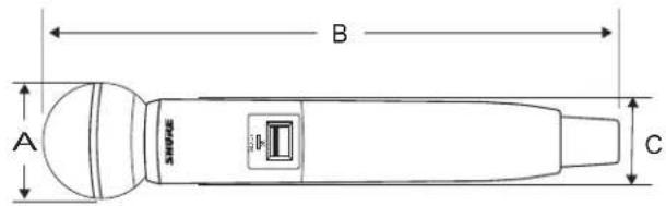
| CBAModel | |||
| 37 mm, (1.5 in.)252 | |||
| 37 mm, (1.5 in.)252 | |||
| 37 mm, (1.5 in.)252 | |||
| 37 mm, (1.5 in.)252 |
Weight
| SM58 | 267 g (9.4 oz.) without batteries |
| BETA 58 | 221 g (7.8 oz.) without batteries |
| SM86 | 275 g (9.1 oz.) without batteries |
| BETA 87A | 264 g (9.3 oz.) without batteries |
Housing
Molded Plastic
Power Requirements
3.7 V Rechargeable Li-Ion
RF Output Power
10 mW E.I.R.P. max
Maximum Input Level
| 146 dB SPLSM58 | |
| 147 dB SPLBETA | |
| 143 dB SPLSM86 | |
| 147 dB SPLBETA |
GLXD4R
Dimensions
42 x 197 x 163 mm (1.7 x 7.8 x 6.4 in.), H x W x D
Weight
907.2 g (32 oz.) without batteries
Housing
steel
Power Requirements
14 to 18 V DC (Tip positive with respect to ring), 550 mA
Spurious Rejection
35 dB, typical
Gain Adjustment Range
-18 to 42 dB in 1 dB steps
Phantom Power Protection
Yes
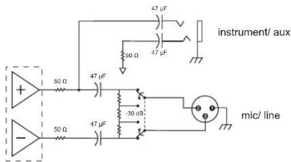
Audio Output
Configuration
| BalancedXLR Output | |
| Impedance balanced6.35 mn |
Impedance
| 100 ΩXLR Output | |
| 100 Ω (50 Ω, Unbalanced)6. |
Full Scale Output
| +12 dBV1/4" (6.35 mr | |
| XLR | LINE setting= +18 dBV, MIC setting= -12 dBV |
Mic/Line Switch
30 dB pad
Pin Assignments
| 1=ground, 2=hot, 3=coldXLR | |
| 6.35 mm (1/4") connector | Tip=audio, Ring=no audio,Sleeve=ground |
Receiver Antenna Input
Impedance
50 Ω
Antenna Type
12 Wave Sleeve Dipole
Maximum Input Level
-20 dBm
Receiver Output Connectors
Certifications
This device complies with part 15 of the FCC Rules. Operation is This subjectless system operates in the globally available ISM band 2, the following two conditions: (1) This device may not cause harmful input at 248r5 MHz. The operation does not require a user license. ence, and (2) this device must accept any interference received, including
interference that may cause undesired operation.
Certified by IC in Canada under RSS-247 and RSS-GEN.
IC: 616A-GLXD1, 616A-GLXD2, 616A-GLXD4RZ2
Certified under FCC Part 15.
This device complies with Industry Canada licence-exempt RSS stand. Operation of this device is subject to the following two conditions: device may not cause interference, and (2) this device must accept ference, including interference that may cause undesired operation of device.
Meets essential requirements of the following European Directives:
• WEEE Directive 2002/96/EC, as amended by 2008/34/EC
• RoHS Directive 2011/65/EU
Note: Please follow your regional recycling scheme for batteries electronic waste
Hereby, Shure Incorporated declares that the radio equipment is in compliance with Directive 2014/53/EU. The full text of the EU declaration of conformity is available at the following internet address: http://www.shure.com/europe/compliance
Authorized European representative:
Shure Europe GmbH
Headquarters Europe, Middle East & Africa
Department: EMEA Approval
Jakob-Dieffenbacher-Str. 12
75031 Eppingen, Germany
Phone: +49-7262-92 49 0
Fax: +49-7262-92 49 11 4
Email: EMEAsupport@shure.de
Information to the user
This equipment has been tested and found to comply with the limits for a Class B digital device, pursuant to Part 15 of the FCC Rules. These limits are designed to provide reasonable protection against harmful interference in a residential installation. This equipment generates uses and can radiate radio frequency energy and, if not installed and used in accordance with the instructions, may cause harmful interference to radio communications. However, there is no guarantee that interference will not occur in a particular installation. If this equipment does cause harmful interference to radio or television reception, which can be determined by turning the equipment off and on, the user is encouraged to try to correct the interference by one or more of the following measures:
- Reorient or relocate the receiving antenna.
- Increase the separation between the equipment and the receiver.
- Connect the equipment to an outlet on a circuit different from that to which the receiver is connected.
- Consult the dealer or an experienced radio/TV technician for help.
運用に際しての注意

- IMPORTANT SAFETY INSTRUCTIONS
- Explanation of Symbols
- WARNING
- California Note:
- System Overview
- Features
- Quick Start for Single Receiver
- Step ①
- Step ②
- Step ③
- Step ④
- Receiver Controls and Connectors
- Receiver Screen
- Transmitters
- ③ Power Switch
- ④ TA4M Input Jack
- ⑤ Micro USB Charging Port
- ⑥ Link Button
- ⑦ Battery Compartment
- ⑧ Microphone Cartridge
- Transmitter Status LED
- Wearing the Bodypack Transmitter
- Wearing the Headworn Microphone
- Correct (slow) Microphone Placement
- Batteries and Charging
- Receiver Charging Bay
- Charging from a USB Port
- LED Status During Charging
- Installing Transmitter Batteries
- Bodypack Transmitter
- Handheld Transmitter
- Charging Times and Transmitter Runtimes
- Important Tips for Care and Storage of Shure Rechargeable Batteries
- GHz Spectrum Overview
- Overcoming the Challenges of 2.4 GHz
- Coexisting with Wi-Fi
- with Challenging Wireless Environments
- Tips to Improve Wireless System Performance
- Additional Tips
- Remote Antenna Placement
- Multiple Receiver Systems
- Setting Up Receivers and Transmitters
- Manually Linking a Transmitter to a Receiver
- Combo Systems
- Operation
- Gain Adjustment
- for the 14 " Locking and Unlocking the Controls
- Locking the Receiver Controls
- Locking the Transmitter Power Switch
- Identifying Linked Transmitters and Receivers Remote ID
- Manually Selecting a Group and Channel
- Selecting a Group
- Firmware
- Connect to the Computer
- Rack-Mounting Instructions
- Resetting Components
- Resetting the Receiver
- Resetting the Transmitter
- Specifications
- Tuning Bandwidth
- Transmit Mode
- Audio Frequency Response
- Dynamic Range
- RF Sensitivity
- Total Harmonic Distortion
- RF Output Power
- Operating Temperature Range
- Storage Temperature Range
- Polarity
- Battery Life
- Channel Count
- GLXD1
- Dimensions
- Weight
- Power Requirements
- Housing
- Input Impedance
- Transmitter Input
- Connector
- Configuration
- Maximum Input Level
- Antenna Type
- Pin Assignments
- GLXD4R
- Spurious Rejection
- Gain Adjustment Range
- Phantom Power Protection
- Audio Output
- Mic/Line Switch
- Receiver Antenna Input
- Impedance
- Certifications
- Information to the user
- 運用に際しての注意
Brand : SHURE
Model : GLXD24R
Category : Uncategorized