
SCM410 - Blender SHURE - Free user manual and instructions
Find the device manual for free SCM410 SHURE in PDF.


| Product Type | Automatic Microphone Mixer |
| Brand | Shure |
| Model | SCM410 |
| Number of Channels | 4 mic/line channels |
| Power Supply | Mains power 100-240 V AC, 50/60 Hz |
| Dimensions (W x D x H) | 483 x 197 x 44 mm (1U rack format) |
| Weight | 2.5 kg |
| Main Functions | Automatic mixing, gain attenuation, balanced output, priority input |
| Connector Types | Female XLR, 6.35 mm jack, screw terminal |
| Frequency Response | 20 Hz to 20 kHz |
| Signal-to-Noise Ratio | > 90 dB |
| Maintenance and Cleaning | Clean with a soft, dry cloth. Do not use solvents. |
| Safety | Disconnect before cleaning. Use only the provided adapter. |
| Spare Parts and Repairability | Contact Shure support for spare parts. Repair by an authorized technician. |
| General Information | Use in conferencing, professional audio. 2-year warranty. |
Frequently Asked Questions - SCM410 SHURE
User questions about SCM410 SHURE
0 question about this device. Answer the ones you know or ask your own.
Ask a new question about this device
Download the instructions for your Blender in PDF format for free! Find your manual SCM410 - SHURE and take your electronic device back in hand. On this page are published all the documents necessary for the use of your device. SCM410 by SHURE.
USER MANUAL SCM410 SHURE
SCM410/SCM410E
FOUR CHANNEL AUTOMATIC MICROPHONE MIXER
SCM410/SCM410E
MÉLANGEUR AUTOMATIQUE À QUATRE CANAUX
SCM410/SCM410E
AUTOMATISCHER 4-KANAL-MIKROFON-MISCHER
SCM410/SCM410E
TABLE-TOP MOUNTING 6
FIXED MOUNTING 6
SCM410 CONNECTIONS 7
LINKING MULTIPLE MIXERS 7
SUGGESTED LOGIC APPLICATIONS 11

This symbol indicates that dangerous voltage constituting a risk of electric shock is present within this unit.

This symbol indicates that there are important operating and maintenance instructions in the literature accompanying this unit.
WARNING: Voltages in this equipment are hazardous to life. No user-serviceable parts inside. Refer all servicing to qualified service personnel. The safety certifications do not apply when the operating voltage is changed from the factory setting.
! IMPORTANT SAFETY INSTRUCTIONS!
- READ these instructions.
- KEEP these instructions.
- HEED all warnings.
- FOLLOW all instructions.
- DO NOT use this apparatus near water.
- CLEAN ONLY with dry cloth.
- DO NOT block any ventilation openings. Install in accordance with the manufacturer's instructions.
- DO NOT install near any heat sources such as radiators, heat registers, stoves, or other apparatus (including amplifiers) that produce heat.
- DO NOT defeat the safety purpose of the polarized or grounding-type plug. A polarized plug has two blades with one wider than the other. A grounding type plug has two blades and a third grounding prong. The wider blade or the third prong are provided for your safety. If the provided plug does not fit into your outlet, consult an electrician for replacement of the obsolete outlet.
- PROTECT the power cord from being walked on or pinched, particularly at plugs, convenience receptacles, and the point where they exit from the apparatus.
-
ONLY USE attachments/accessories specified by the manufacturer.
-
USE only with a cart, stand, tripod, bracket, or table specified by the manufacturer, or sold with the apparatus. When a cart is used, use caution when moving the cart/apparatus combination to avoid injury from tip-over.
-
UNPLUG this apparatus during lightning storms or when unused for long periods of time.
- REFER all servicing to qualified service personnel. Servicing is required when the apparatus has been damaged in any way, such as power-supply cord or plug is damaged, liquid has been spilled or objects have fallen into the apparatus, the apparatus has been exposed to rain or moisture, does not operate normally, or has been dropped.
- DO NOT expose the apparatus to dripping and splashing. DO NOT put objects filled with liquids, such as vases, on the apparatus.
- The MAINS plug or an appliance coupler shall remain readily operable.
- The airborne noise of the apparatus does not exceed 70dB (A).
- Apparatus with CLASS I construction shall be connected to a MAINS socket outlet with a protective earthing connection.
- To reduce the risk of fire or electric shock, do not expose this apparatus to rain or moisture.
- Do not attempt to modify this product. Doing so could result in personal injury and/or product failure.
WARNING: This product contains a chemical known to the State of California to cause cancer and birth defects or other reproductive harm.
DESCRIPTION
The Shure Model SCM410/E is a four-channel automatic microphone mixer for use in sound reinforcement, audio recording, and broadcast applications. The SCM410 dramatically improves audio quality in any application where multiple microphones are required. Any low-impedance dynamic or condenser microphone (including wireless) can be used with the SCM410. Multiple SCM410 mixers can be linked to other SCM410 mixers, as well as to Shure Models FP410, SCM810, and SCM800.
Each input channel has a two-band equalizer and three logic terminals. The equalizer reduces unwanted low-frequency audio pickup and makes different microphone types-lavaliers, boundary and handheld-sound similar. The logic terminals can be used to control external devices.
The SCM410 operates on 100-120 Vac power and the SCM410E operates on 220-240 Vac power. Each mixer is supplied with a power cord, rack-mounting hardware, and a link cable.
FEATURES
- Fast, noise-free microphone selection, which automatically adjusts to changes in background noise
• Automatic gain adjustment as additional microphones are activated-NOMA (Number of Open Microphones Attenuated)
• Last Mic Lock-On circuit maintains ambient sound
• Fits in half-rack space - Adjustable EQ for each channel
• Active balanced microphone-level XLR inputs and an active balanced Mic/Line level XLR output
• Unbalanced auxiliary-level phono output
• Bi-color channel activation and clipping LEDs
• Peak-responding output limiter with LED indicator
• Peak-responding output level meter
OPERATING PRINCIPLES
The operating concept behind the SCM410 Automatic Mixer is Shure's patented* IntelliMix® circuitry. Intellimix delivers seamless automatic mixing by combining three separate functions:
- Noise Adaptive Threshold. Distinguishes between constant background noise (such as air conditioning) and changing sound (such as speech) for each input channel. It continuously adjusts the activation threshold so that only speech levels louder than the background noise activate a channel.
- MaxBus. Controls the number of channels that may be activated for a single sound source. One talker activates only one channel, even if multiple microphones "hear" that talker.
- Last Mic Lock-On. Keeps the most recently activated microphone open until another microphone is activated. Without Last Mic Lock-On, a long pause in conversation would cause all microphones to turn off, which would sound as if the audio signal had been lost. Last Mic Lock-On ensures that background ambience is always present.
*U.S. Patents 4,658,425 and 5,297,210. IntelliMix is a registered trademark of Shure Incorporated.
FRONT PANEL
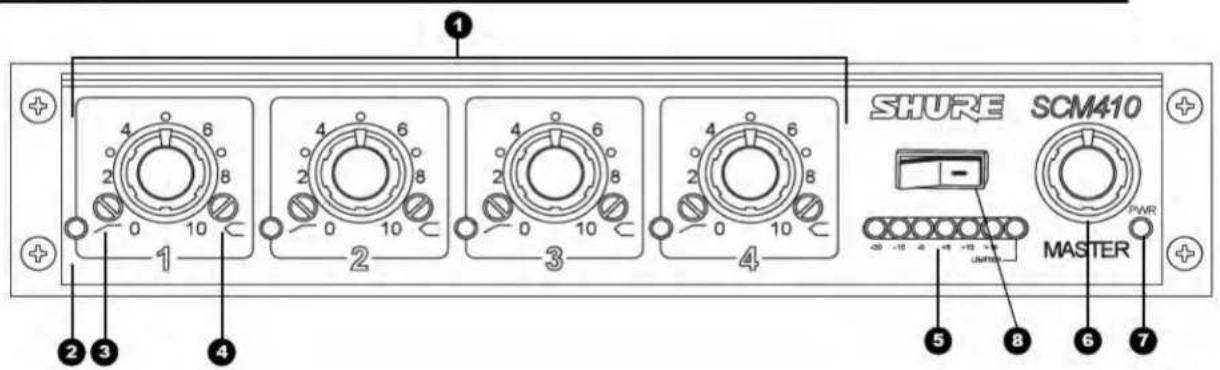
① Microphone Channel Gain Controls 1 - 4: Allows adjustment of microphone gain.
② Input LED 1 - 4: Lights green when channel is active; lights red at 6 dB below clipping level.
3 Low-Cut Filter 1 - 4: Provides adjustable low-frequency rolloff (high pass), reducing presence of undesirable low-frequency signals.
4 High-Frequency Shelving Filter 1 - 4: Provides level boost or cut in mid/high-frequency region for reduced sibilance from vocal microphones, or to compensate for off-axis coloration in lavalier microphones.
5 Output Level Meter: Six-segment LED meter indicates peak output signal level in dBu (0 dBu = 0.775V). The red LED illuminates when the output is 6 dB below clipping. The last LED indicates limiter action.
6 MASTER Level Control: Controls overall output level.
7 POWER LED: Lights green when mixer is plugged into a power source.
8 POWER Switch
Note: Country dependent
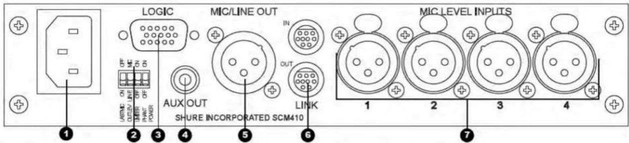
Power Connector: Unit is energized when the power cord is plugged into a 100-120 Vac (SCM410) or 220-240 Vac (SCM410E) power source. NOTE: There is no power On/Off switch on this mixer.
② DIP Switch: The 4-position DIP switch provides additional functions. Refer to the "DIP Switch Functions" section.
3 Microphone Logic Connector: High density DB-15 male connector provides connection to GATE OUT, MUTE IN, and OVERRIDE IN logic terminals on each channel. Refer to the "Advanced Functions" section. NOTE: THIS IS NOT A VGA MONITOR PORT.
4 AUX OUT Phono Connector: Feeds consumer-level audio equipment, such as a tape recorder, VCR, or video camera. Not affected by MIC/LINE switch.
DIP SWITCH FUNCTIONS
The rear panel DIP switches, shown in Figure 1, provide the functions listed in the table below.
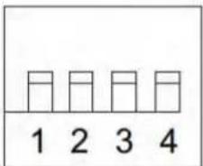
DIP SWITCHES FIGURE 1
| Last Mic Lock-On | XLR Output Level | Limiter | 12V Phantom Power | |
| Switch Number | 1 | 2 | 3 | 4 |
| Switch Up | All mics off after hold time | Mic Level | ON | ON |
| Switch Down | ON* | Line Level* | OFF* | OFF* |
*Factory setting.
⑤ MIC/LINE XLR OUTPUT Connector: Can be set for microphone or line-level output via a DIP switch.
6 LINK IN/OUT Connector: Permits multiple SCM410/E, FP410, SCM810, SCM800, or AMS8100 mixers to be linked, creating additional inputs.
7 MIC LEVEL XLR INPUT Connectors: Active balanced microphone-level XLR inputs. For instructions on how to modify the level of these inputs, refer to the "Internal Modifications" Addendum.
Last Mic Lock-On: Keeps the most recently activated microphone turned on until another microphone is activated. When defeated, microphones turn off after their default hold time.
XLR Output Level: Sets the level of the XLR output to line or microphone level. Make sure the output level matches the input level of the device connected to the SCM410.
NOTE: The output level does not affect the auxiliary output (AUX OUT) level.
Limiter: Activates the output limiter and sets it to a default threshold of +16 dBu (see Internal Modifications Addendum for other threshold settings).
12V Phantom Power: When this switch is in the ON position, the SCM410 provides 12Vdc phantom power to each XLR microphone input. This function is particularly useful when using condenser microphones, since most condenser microphones require phantom power.
NOTE: Phantom power does not affect the operation of balanced dynamic microphones. They can be connected to the SCM410 in combination with condenser microphones that use phantom power. For instructions on how to disable phantom power by channel, refer to the "Internal Modifications" Addendum.
SUPPLIED HARDWARE
- 4 rubber feet
- 1 rackmount bracket, long
- 1 rackmount bracket, short
• 2 straddle brackets
RACK MOUNTING
The SCM410 is supplied with hardware for mounting one or two units to a 19-inch audio equipment rack. The hardware can also be used to rack mount other Shure products, including the SCM268, SCM262, DFR11EQ, and the DP11EQ.
Single Mixer (Half Rack) Installation
- Attach the short and long rackmount brackets to the SCM410/E with eight (8) of the supplied bracket screws.
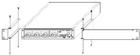
INSTALLING HALF-RACK MOUNTING BRACKETS
- Place the mixer in an equipment rack and secure it with the supplied rackmount screws and plastic washers.
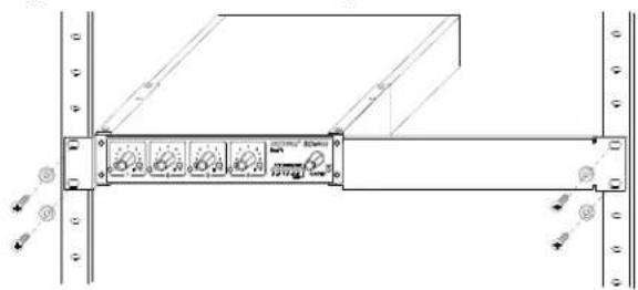
• 10 bracket screws, 6 mm (1/4 in.)
• 4 rackmount screws, 2.54 cm (1 in.)
- 4 plastic washers
• 4 wood screws, 1.25 cm (1/2 in.)
Dual Mixer (Full Rack) Installation
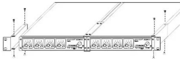
- Place the two mixers side-by-side and connect them with two (2) straddle brackets. The brackets should straddle the recessed edges on the top and bottom of each mixer.

INSTALLING STRADDLE BRACKETS
- Fasten the straddle brackets using eight (8) bracket screws.
- Attach the short rackmount brackets to the outsides of the combined mixers with eight (8) of the bracket screws.
natural_image
Diagram of a rack-mounted server unit with multiple ports and indicator lights (no text or labels visible)INSTALLING FULL-RACK MOUNTING BRACKETS
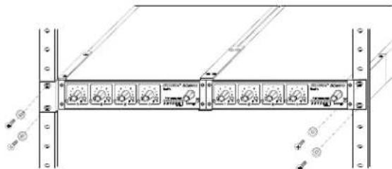
- Place the mixer in an equipment rack, using the supplied rack-mount screws and plastic washers.
Adhere the four (4) supplied rubber feet to the bottom of the mixer at each corner. This will keep it from sliding and protect the table surface.
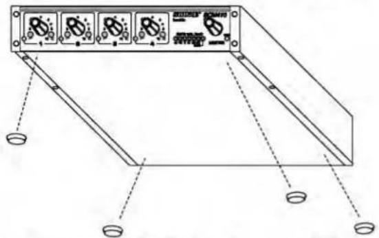
ATTACHING RUBBER FEET FOR TABLE-TOP MOUNTING
FIXED MOUNTING
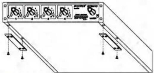
TOP MOUNT
- Fasten the straddle brackets to the recessed edges of the chassis, using four (4) bracket screws.
natural_image
Technical line drawing of a mechanical or electrical component with four ports and mounting brackets (no text or symbols)INSTALLING STRADDLE BRACKETS FOR TOP MOUNTING
- Fasten the straddle brackets to the top of the mounting surface, using the four (4) supplied wood screws.
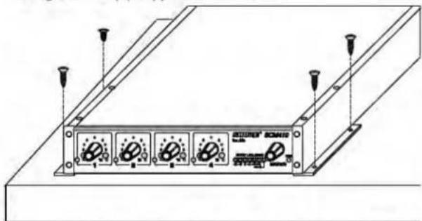
SECURING MIXER TO TOP MOUNTING SURFACE
HANGING MOUNT
Note: The hardware provided is for attachment to wood. Other surfaces require the use of appropriate hardware rated for 15 lbs. or more.
- Fasten the straddle brackets to the top of the mixer.
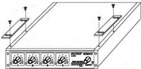
INSTALLING STRADDLE BRACKETS FOR HANG MOUNTING
- Fasten the straddle brackets to the bottom of the mounting surface, using the four (4) supplied wood screws.
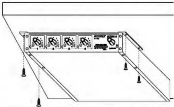
SECURING MIXER TO BOTTOM MOUNTING SURFACE
- Connect microphone signal sources to the Channel Input connectors. Use conventional 2-conductor shielded audio cables.
-
If any condenser microphones are connected, set the +12V phantom power DIP switch to ON.
-
Connect the SCM410 Mic/Line Level Output to the input of mixers, EQs, amplifiers or recorders.
-
Connect the power cord to 100-120 Vac (SCM410) or 220-240 Vac (SCM410E)
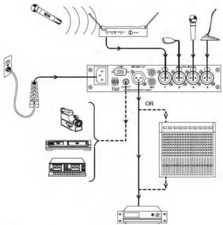
flowchart
graph TD
    A["Radio Cable"] --> B["Switch"]
    C["Radio Station"] --> D["Radio System"]
    E["Audio Receiver"] --> F["Audio Output"]
    G["Audio Module"] --> H["Audio Control System"]
    I["Audio Display"] --> J["Audio System"]
    K["Audio Headset"] --> L["Audio System"]
    M["Audio Signal"] --> N["Audio System"]
    O["Audio Output"] --> P["Audio System"]
    Q["Audio System"] --> R["Audio System"]
    S["Audio System"] --> T["Audio System"]
    U["Audio System"] --> V["Audio System"]
    W["Audio System"] --> X["Audio System"]
    Y["Audio System"] --> Z["Audio System"]
    AA["Audio System"] --> AB["Audio System"]
    AC["Audio System"] --> AD["Audio System"]
    AE["Audio System"] --> AF["Audio System"]
    AG["Audio System"] --> AH["Audio System"]
    AI["Audio System"] --> AJ["Audio System"]
    AK["Audio System"] --> AL["Audio System"]
    AM["Audio System"] --> AN["Audio System"]
    AO["Audio System"] --> AP["Audio System"]
    AQ["Audio System"] --> AR["Audio System"]
    AS["Audio System"] --> AT["Audio System"]
    AU["Audio System"] --> AV["Audio System"]
    AW["Audio System"] --> AX["Audio System"]
    AY["Radio Cable"] --> AZ["Switch"]
    BA["Radio Station"] --> BB["Switch"]
    BC["Audio Receiver"] --> BD["Audio Output"]
    BE["Audio Module"] --> BF["Audio System"]
    BG["Audio Headset"] --> BH["Audio System"]
    BI["Audio Signal"] --> BJ["Audio System"]
    BK["Audio System"] --> BL["Audio System"]
    BM["Audio System"] --> BN["Audio System"]
    BO["Audio System"] --> BP["Audio System"]
    BZ["Audio Output"] --> CA["Audio System"]
    CB["Audio System"] --> CC["Audio System"]
    CD["Audio System"] --> CE["Audio System"]
    CF["Audio System"] --> CG["Audio System"]
    CH["Audio System"] --> CI["Audio System"]
    CJ["Audio System"] --> CK["Audio System"]
LINKING MULTIPLE MIXERS
If more than four inputs are needed, multiple Shure SCM410, FP410, or SCM810 mixers can be linked by connecting the LINK OUT of the first mixer to the LINK IN of the next mixer, and so on. See Figure 2. Leave the LINK IN jack of the first mixer and the LINK OUT jack of the last mixer unconnected.
When properly linked, the mixers will operate as a system. Automatic mixing functions will be shared by all units. All input signals appear at all linked mixer outputs. Each mixer's Master level control only controls its own output. However, actual off-attenuation will increase as more mixers are linked. This reduces excessive noise and reverberation contributed by the increased number of microphones.
IMPORTANT: When using logic terminals on linked mixers, connect the LOGIC GROUND terminals of each unit together.
NOTE: SCM410 link connections are unbalanced. To minimize hum and noise, avoid using longer link cables. Use high quality, shielded cable, and keep them away from sources of magnetic or electrical noise, such as power transformers or
light dimmers. To minimize ground currents, make sure linked mixers are connected to the same AC power mains.
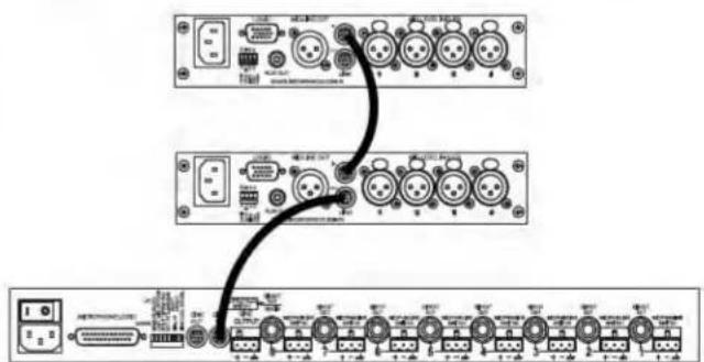
LINKED SCM410 AND SCM810 MIXERS FIGURE 2
- Adjust each channel level so that its Overload LED flickers only during very loud speech or noise.
-
Adjust the Low-Cut and High-Frequency controls adjacent to each Input Gain control so that the microphones sound similar.
-
Adjust the Master level control for the required output level, as indicated by the output peak meter. The SCM410 is now ready for use.
LIMITER
Output limiters prevent distortion during loud program peaks without affecting normal program levels. This keeps the devices connected to the SCM410 output from becoming overloaded. Increasing individual or Master controls on the SCM410 increases average output and, in turn, the amount of limiting.
The limiter may be turned on via the rear panel DIP switch. The default limiter threshold is +16 dBu. As supplied, the limiter is defeated.
NOTE: Limiter thresholds can be changed from their factory settings. Refer to the "Internal Modifications" Addendum.
EQUALIZER FUNCTIONS
Low Cut Filter (High-Pass)
Low-cut filters are used to reduce unwanted low frequency sounds such as footsteps, motorized traffic, and to control proximity effect. The SCM410 has a one-pole, low-cut (high-pass) filter of 6 dB per octave. The low-cut filter allows all frequencies above its cutoff point to pass through unchanged. Frequencies below the cutoff are attenuated (see Figure 3). The cutoff point is defined as the frequency where the signal has dropped 3 dB relative to the flat, or bandpass, region. Below the cutoff point, the filter exhibits increasingly more attenuation as the frequency diminishes.
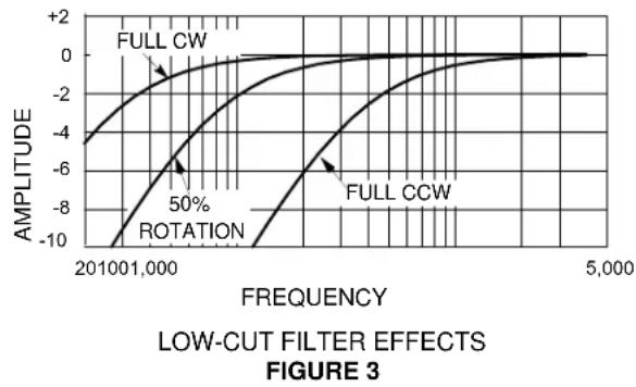
line
| FREQUENCY | AMPLITUDE (FULL CW) | AMPLITUDE (FULL CCW) | | --------- | ------------------- | -------------------- | | 201001,000 | -4.0 | -8.0 | | 5,000 | 0.0 | 0.0 |High-Frequency Shelving
The fixed-frequency equalizer produces a 6 dB boost or cut at 5 kHz and above (see Figure 4). High-frequency shelving is extremely useful for boosting flat frequency response and tempering sibilant vocal microphones or enhancing the sound of off-axis lavalier microphones.
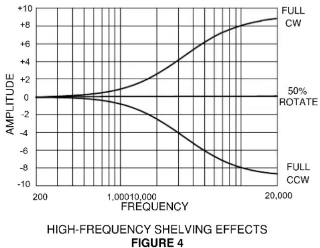
line
| FREQUENCY | FULL CW | FULL CCW | 50% ROTATE | | --------- | ------- | -------- | ---------- | | 200 | 0 | 0 | 0 | | 1,000 | ~2 | ~-2 | 0 | | 10,000 | ~4 | ~-6 | 0 | | 20,000 | ~8 | ~-9 | 0 |Measurement Conditions (unless otherwise specified): Line voltage 120 Vac, 60 Hz (SCM410) or 230 Vac, 50 Hz (SCM410E); full gain; 1 kHz, one channel activated; source impedances: Mic 150Ω; terminations: Line/Mic Aux 10 kΩ
Frequency Response (at 1 kHz, channel controls centered) 50 Hz to 20 kHz ±2 dB; -3 dB corner at 25 Hz
Voltage Gain (typical, controls full clockwise)
| Output | |||
| Input Line Mic Aux | |||
| Low-impedance mic (150 Ω) | 80 dB | 40 dB | 68 dB |
Inputs
| Impedance | |||
| Input | Designed for use with | Actual (typical) | Input Clipping Level |
| Mic | 19-600 Ω | 1.4 kΩ | -14 dBV |
Outputs
| Impedance | |||
| Output | Designed for use with | Actual (typical) | Output Clipping Level |
| Line | ≥5k Ω | 300 Ω | +22 dBV |
| Mic | ≥600 Ω | 3 Ω | -20 dBV |
| Aux | ≥10k Ω | 1.5 k Ω | +12 dBV |
Total Harmonic Distortion
<0.1% at +4 dBu output level, 50 Hz to 20 kHz (through 22 Hz to 22 kHz filter; Input at 12 o'clock and Master at 12 o'clock, all other controls full counterclockwise)
Equivalent Input Noise: (150 Ω source; A-Weighted)
-127 dBV max., -129 dBV typical
Output Noise (channel controls full counterclockwise
A-Weighted):
Master full counterclockwise: -101 dBV
Master full clockwise: -67 dBV
Common Mode Rejection
70 dB at 1 kHz
Polarity
All inputs to all outputs are non-inverting
Input Channel Activation
Attack Time: 4 ms
Hold Time: 0.4 s
Decay Time: 0.5 s
Off-Attenuation
13 dB
Overload and Shorting Protection
Shorting outputs, even for prolonged periods, causes no damage. Microphone inputs are not damaged by signals up to +10 dBV (3V)
Equalization
Low-frequency: 6 dB/octave cut, adjustable corner from 25 to 320 Hz
High-frequency: shelving Filter, ±6 dB at 5 kHz, rising to ±8 dB at 10 kHz,
Limiter
Type: Peak
Threshold: +16 dBu (at output)
Attack Time: 2 ms
Recovery Time: 300 ms
Indicator: Lights red when limiting occurs
Input LEDs
Green on channel activation, red at 6 dB below clipping
Phantom Power
12 Vdc open-circuit through 680 Ω resistors
Operating Voltage
SCM410: 100-120 Vac rated nominal, 50/60 Hz, 100 mA (maximum)
SCM410E; 220-240 Vac rated nominal, 50/60 Hz, 50 mA (maximum)
Mains Inrush Current (230 Vac, SCM410E only)
0.7 A peak
Temperature Range
Operating: -7^ to 49^ C (20° to 120° F)
Storage: -29^ to 74^ C (-20° to 165° F)
Overall Dimensions
44 mm H x 219 mm W x 267 mm D (1 ^-3 / 4 x 8 ^-5 / 8 x 10 ^-1 / _2 in.)
Net Weight
1.75 kg (3.86 lbs)
Certifications
SCM410: UL LISTED to UL 60065 and cUL LISTED to CAN/CSA-C22.2 No. 60065-3 Canada.
SCM410E: Conforms to applicable European Union Directives. Low Voltage Directive, 2006/95/EC: Certified to EN 60065. Eligible to bear CE marking. Conforms to European EMC Directive 2004/108/EC. Meets Harmonized Standards EN55103-1:1996 and EN55103-2:1996 for residential (E1) and light industrial (E2) environments.
Conforms to the relevant requirements of Regulation (EC) No. 1275/2008, as amended.
The CE Declaration of Conformity can be obtained from Shure Incorporated or any of its European representatives. For contact information please visit www.shure.com
The CE Declaration of Conformity can be obtained from: www.shure.com/europe/compliance
Authorized European Representative:
Shure Europe GmbH
Headquarters Europe, Middle East & Africa
Department: EMEA Approval
Jakob-Dieffenbacher-Str. 12
75031 Eppingen, Germany
Phone: +49-7262-92 49 0
Fax: +49-7262-92 49 11 4
Knob, Master (white)....95A8238
Knob, Channel Gain (blue) 95B8238
Line (Power) Cord (SCM410) 95B8389
Line (Power) Cord (SCM410E)....95B8778
Link Cable....95B8889
Fuse, SCM410
(5 x 20 mm, T 125mA L, 250V, time delay)......80AA730
Fuse, SCM410E
(5 x 20 mm, T 50mA L, 250V, time lag) .....80J380
Long Rack Mount Bracket....53A8484
Short Rack Mount Bracket....53E8484
Straddle Bracket 53B8443
Bagged Hardware Kit....90AW8100
Optional Accessories
Line (Power) Cord, 230-240 Vac (UK) .....95A8713
External 50 dB Line Pad.....A15LA
Service Statement
For additional service or parts information, please contact the Shure Service Department at 1-800-516-2525. Outside the United States, please contact your authorized Shure Service Center.
CAUTION: Use of Advanced Functions is recommended only for qualified audio technicians.
LOGIC CONNECTION SPECIFICATIONS
The SCM410 logic functions expand the range of installation and control options. Logic can be used for everything from simple cough switches to elaborate computer-controlled room systems. (Shure's AMS Update publication contains additional applications of advanced logic. This publication is available by contacting the Shure Applications Department.) The following logic functions are available for each channel:
GATE OUT: Follows channel gating and goes to logic "low" (sinks current) when microphone is gated on. 500 mA of current sinking ability is provided (see Figure 5A).
MUTE IN: Applying logic "low" (from GATE OUT or a switch closure to logic ground) gates channel off (see Figure 5B). Channel output drops to -∞.
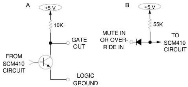
LOGIC EQUIVALENT CIRCUIT DIAGRAM FIGURE 5
OVERRIDE IN: Applying logic "low" (from GATE OUT or a switch closure to logic ground) forces channel on (see Figure 5B). When both Mute and Override are activated, Mute takes precedence (see Internal Modifications Addendum for Override precedence).
LOGIC GROUND: Logic ground is distinct from audio ground. Make all logic ground connections to this pin, including power supply ground of external logic circuitry. To avoid switching clicks, do not connect logic ground to audio, chassis or rack grounds.
Logic controls are accessed through the high density DB-15 multi-pin connector on the rear panel (Figure 6). Pin connections are shown in the following table.
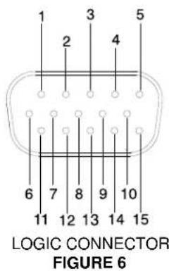
LOGIC CONNECTIONS
| PinNo. | Logic Function Logic | Function Pin | No. |
| 1 OVERRIDE IN 1 GATE OUT 1 | 6 | ||
| 2 OVERRIDE IN 2 GATE OUT 2 | 7 | ||
| 3 OVERRIDE IN 3 GATE OUT 3 | 8 | ||
| 4 GATE OUT 4 GATE OUT 4 4 | |||
| 5 LOGIC GROUND OVERRIDE IN 1 1 | |||
| 6 GATE OUT 1 OVERRIDE IN 2 | 2 | ||
| 7 GATE OUT 2 OVERRIDE IN 3 | 3 | ||
| 8 GATE OUT 3 OVERRIDE IN 4 | 14 | ||
| 9 NO CONNECTION | MUTE IN 1 11 | ||
| 10 | MUTE IN 4 | MUTE IN 2 12 | |
| 11 | MUTE IN 1 | MUTE IN 3 13 | |
| 12 | MUTE IN 2 | MUTE IN 4 10 | |
| 13 | MUTE IN 3 | LOGIC GROUND | 5 |
| 14 | OVERRIDE IN 4 NO CON | NECTION 15 | |
| 15 | NO CONNECTION | NO CONNECTION | 9 |
This section contains suggestions on the uses of the SCM410's logic capabilities. Note that uses of these functions are not limited to the listed applications. The user is limited only by imagination and creativity. For additional suggestions and solutions to installation problems, contact the Shure Applications Department.
COUGH BUTTON
The talker can turn off his or her microphone during coughing or private conversations by installing an SPST pushbutton switch between the MUTE IN and Logic Ground pins for each channel to be modified (see Figure 7). When a channel is muted, no audio is passed. (See Dead Zone on MUTE IN Defeat paragraph in the Internal Modifications Addendum for more information on MUTE IN logic.)
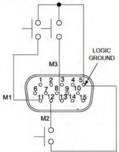
COUGH BUTTONS FIGURE 7
CHAIRPERSON-CONTROLLED MUTING
The chairperson can, by activating a switch, silence all other microphones and be heard without interruption. For operation in this mode, connect all the MUTE IN pins together except that of the chairperson's channel, and wire an SPST pushbutton or toggle switch between those MUTE IN and Logic Ground pins (see Figure 8).
An alternative to a switch is to connect the chairperson's GATE OUT to the MUTE IN of other channels. When the chairperson's microphone activates, all other microphones mute.
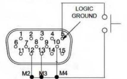
CHAIRPERSON-CONTROLLED MUTING FIGURE 8
REMOTE CHANNEL-ON INDICATORS
Remote indicators can be used to indicate when a talker's microphone is on. Connect the LEDs and a 5-volt supply to the GATE OUT pins (See Figure 9). To avoid switching clicks in the audio output, do not ground the power supply negative terminal in the audio system or rack ground.
IMPORTANT: If a single cable is used for the microphone audio signal and the LED dc power, separate shielded pairs must be used. Failure to carry the dc power on a shielded pair may result in audible clicking due to capacitive coupling between the dc power lines and microphone lines.
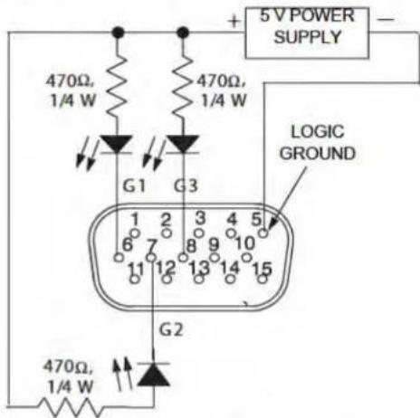
REMOTE CHANNEL-ON INDICATORS FIGURE 9
DISABLING THE GATING FUNCTION (BYPASS)
To keep certain microphones on at all times, wire the desired microphone channel's OVERRIDE IN pins together to the Logic Ground pin. The selected channels now function as they would in a non-automatic mixer (see Figure 10). To perform this modification internally on the mixer, refer to the Shorting Override In to Logic Ground Internally paragraph in the Internal Modifications Addendum.
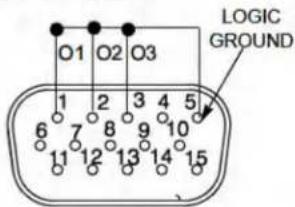
GATING BYPASS FIGURE 10
INHIBITING GATING FOR UNWANTED SOUNDS
MaxBus attempts to activate only one microphone per sound source. Muting a microphone channel prevents its audio from appearing at the mixer's output. However, the muted microphone still communicates with other mic channels via MaxBus. A sound source picked up by a muted microphone will not activate other microphones.
Sound sources that may cause unwanted microphone channel activation include:
• Heating, ventilation, or air conditioning systems
• A noisy fax machine or printer
• A squeaky door
• A paging system loudspeaker
• An audio teleconferencing return signal loudspeaker
The SCM410 can prevent these and similar sounds from activating microphones as follows:
- Place one microphone near the unwanted sound source. Connect that microphone's signal to a channel input, -or- connect the unwanted sound source directly into a channel input.
- Mute that channel using the logic terminal (see Figure 11). To perform this modification internally on the mixer, refer to the Shorting Mute In to Logic Ground Internally paragraph in the Internal Modifications Addendum.
- Adjust the channel gain control just past the level where unwanted sounds do not activate other microphones in the system. If the channel gain is set too high, the other microphones may not be activated by the desired sounds. If set too low, unwanted sounds will continue to activate other microphones.
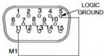
INHIBITING GATING FOR UNWANTED SOUNDS FIGURE 11
LOUDSPEAKER MUTING
Some applications require a loudspeaker to be placed near each talker to provide audio reinforcement, or to permit telephone conversation or conference monitoring. Each loudspeaker can cause feedback unless it is automatically switched off when the talker near it speaks. To provide this function, connect the GATE OUT terminal of each channel to a separate loudspeaker muting relay (See Figure 12). Recommended relays are Radio Shack 275-248, Omron G2R-14-DC12 (Digi-Key number Z745-ND), Potter & Brumfield R10-E1Y2-V185 (Newark number 45F106), or equivalent.
NOTE: A diode across each relay coil is required to suppress inductive voltage spikes which may damage the SCM410.
An existing sound system using 24-volt relays can be used with the SCM410 without modification if the relay coil current draw is under 500 mA.
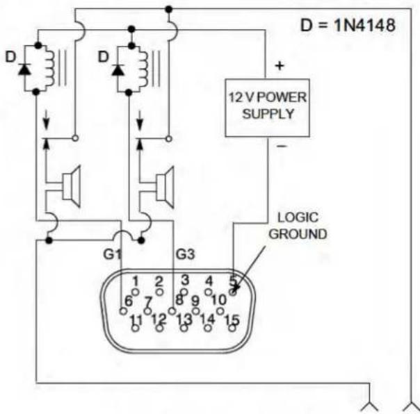
LOUDSPEAKER MUTING FIGURE 12
"FILIBUSTER" MODE
Normally, when several people talk, each microphone gates on so that no speech is missed. In "filibuster" mode, a microphone remains gated on until the talker pauses long enough for that microphone to gate off. No other microphone can gate on until that microphone gates off. This prevents talkers from being interrupted.
To establish filibuster mode, refer to Figure 13 and proceed as follows:
- Perform the Mute to Inhibit modification as presented in the Internal Modifications Addendum.
- Connect all the MUTE IN pins together on the modified channels.
- Connect all the GATE OUT pins together on the modified channels.
- Connect the GATE OUT pin of one modified channel to the MUTE IN pin of another modified channel.
- Turn the Last Mic Lock-On switch to OFF.
NOTE: To prevent high-frequency oscillation, do not wire a GATE OUT pin to a MUTE IN pin on the same channel unless the Mute to Inhibit modification has been made.
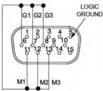
"FILIBUSTER" MODE FIGURE 13
INHIBIT FUNCTION
For information on the inhibit function, refer to the Internal Modifications Addendum.
REMOTE VOLUME CONTROL
The level of the Aux or Master output can be controlled from an external VCA (Voltage Controlled Amplifier) such as the RU-VCA1 from Radio Design Labs (Tel. 1-800-281-2683, or www.rdlnet.com). To connect a VCA to the SCM410, proceed as follows:
- Connect the SCM410 Line output to the VCA line input.
- Connect the VCA line output to the external device.
- For remote Master level control, set the SCM410 Master control to 5.
DIODE ISOLATION OF LOGIC CONTROLS
Two or more control functions that use the same logic pins can be isolated with diodes, as shown in Figure 14. With this modification, a channel can be muted by an overall group mute switch, or by its own cough button.
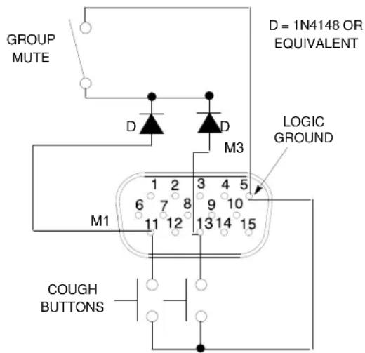
DIODE ISOLATION OF LOGIC TERMINALS FIGURE 14
EXTERNAL LOGIC DEVICES
SCM410 logic levels are directly compatible with TTL and 5V CMOS logic families. Mixer logic may be used with 15V CMOS logic if a pull-up resistor is used with each GATE output. See Figure 15.
NOTE: For information on logic gate use, refer to the TTL Cookbook and CMOS Cookbook, both by D. Lancaster, Howard Sams Publishing Co.
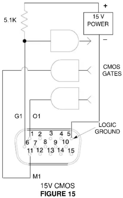
DIGITAL CONTROLS OR MICROCOMPUTERS
The SCM410 logic pins can interface with custom-designed digital control circuitry or microcomputers for unlimited possibilities of system control functions.
TABLE DES MATIÈRES
DESCRIPTION 15
AVANTAGES 15
PRINCIPES DE FONCTIONNEMENT 15
PANNEAU FRONTAL 15
PANNEAU ARRIÈRE 16
PANNEAU ARRIÈRE DU MODÈLE SCM410
FIGURE 2
natural_image
Technical line drawing of a server rack with indicator lights and ports (no text or symbols)MONTAGE DES SUPPORTS D'INSTALLATION EN DEMI-RACK FIGURE 4
INSTALLATION EN RACK D'UN MÉLANGEUR SCM410/E UNIQUE FIGURE 5
MONTAGE DE DEUX MÉLANGEURS (RACK ENTIER)
natural_image
Technical line drawing of a server rack with indicator lights and connectors (no text or symbols)MONTAGE DES SUPPORTS DE JUMELAGE FIGURE 6
MONTAGE DES SUPPORTS DE MONTAGE EN RACK ENTIER FIGURE 7
INSTALLATION EN RACK DE DEUX MÉLANGEURS SCM410/E FIGURE 8
ADHÉSION DES SUPPORTS EN CAOUTCHOUC POUR INSTALLATION SUR TABLE FIGURE 9
INSTALLATION FIXE
INSTALLATION SUR PARTIE SUPÉRIEURE
natural_image
Technical diagram of a mechanical or electrical component with four ports and mounting brackets (no text or symbols)MONTAGE DES SUPPORTS DE JUMELAGE POUR INSTALLATION SUR PARTIE SUPÉRIEURE FIGURE 10
natural_image
Technical line drawing of a server rack with four ports and mounting brackets (no text or symbols)FIXATION DU MÉLANGEUR À UNE SURFACE D'INSTALLATION SUPÉRIEURE FIGURE 11
INSTALLATION SUSPENDUE
natural_image
Technical line drawing of a mechanical assembly with mounting brackets and hanging tassels (no text or symbols)FIXATION DU MÉLANGEUR À UNE SURFACE D'INSTALLATION INFÉRIEURE FIGURE 13
CONNEXIONS SCM410
MÉLANGEURS SCM410 ET SCM810 RELIÉS FIGURE 15
natural_image
Technical line drawing of a server rack with indicator lights and ports, no text or symbols presentnatural_image
Technical line drawing of a server rack with indicator lights and connectors (no text or symbols)natural_image
Technical line drawing of a server rack with four ports and connection points (no text or symbols)PANEL TRASERO DEL MODELO SCM410
FIGURA 2
natural_image
Technical line drawing of a server rack with indicator lights and ports (no text or symbols)INSTALACION DE LAS ESCUADRAS DE MONTAJE EN MEDIA POSICION DE BASTIDOR FIGURA 4
MONTAJE EN BASTIDOR DE UNA CONSOLA MEZCLADORA SCM410/E FIGURA 5
natural_image
Technical line drawing of a server rack with indicator lights and connectors (no text or symbols)INSTALACION DE LAS ESCUADRAS DE EMPALME FIGURA 6
natural_image
Diagram of a rack-mounted server unit with multiple ports and indicator lights (no text or labels)INSTALACION DE LAS ESCUADRAS DE MONTAJE EN UNA POSICION DE BASTIDOR FIGURA 7
MONTAJE EN BASTIDOR DE DOS CONSOLAS MEZCLADORAS SCM410/E FIGURA 8
MONTAJE EN MESA
ADHESION DE LOS PIES DE CAUCHO PARA EL MONTAJE EN MESA FIGURA 9
MONTAJE FIJO
MONTAJE EN SUPERFICIE
natural_image
Technical line drawing of a server rack with four ports and mounting brackets (no text or symbols)INSTALACION DE LAS ESCUADRAS DE EMPALME PARA EL MON- TAJE EN SUPERFICIE FIGURA 10
natural_image
Diagram of a server rack with four ports and mounting brackets (no text or symbols)FIJACION DE LA CONSOLA MEZCLADORA A LA SUPERFICIE DE MONTAJE SUPERIOR FIGURA 11
MONTAJE EN PARTE INFERIOR
natural_image
Technical line drawing of a mechanical or electrical assembly with mounting brackets and hanging components (no text or symbols)FIJACION DE LA CONSOLA MEZCLADORA A LA SUPERFICIE DE MONTAJE INFERIOR FIGURA 13
Fusible, SCM410 (5 x 20 mm, T 125mA L,
Fusible, SCM410E (5 x 20 mm, T 50mA L,
PANNELLO POSTERIORE DEL MODELLO SCM410
FIGURA 2
natural_image
Technical line drawing of a server rack with ports and indicator lights (no text or symbols)INSTALLAZIONE DELLE STAFFE DI MONTAGGIO DA SEMI-RACK FIGURA 4
MONTAGGIO SU RACK DI UN SINGOLO MIXER SCM410/E FIGURA 5
INSTALLAZIONE DI DUE MIXER (RACK INTERO)
natural_image
Technical line drawing of a server rack with indicator lights and connectors (no text or symbols)INSTALLAZIONE DELLE STAFFE DI MONTAGGIO DA RACK INTERO FIGURA 7
MONTAGGIO SU RACK DI DUE MIXER SCM410/E FIGURA 8
FISSAGGIO DEI PIEDINI IN GOMMA PER IL MONTAGGIO SU RIPIANO FIGURA 9
MONTAGGIO FISSO
MONTAGGIO SULLA PARTE SUPERIORE
natural_image
Technical diagram of a server rack with four ports and mounting brackets (no text or symbols)natural_image
Diagram of a server rack with four ports and indicator lights (no text or labels)FISSAGGIO DEL MIXER ALLA SUPERFICIE DI MONTAGGIO SUPERIORE FIGURA 11
MONTAGGIO SULLA PARTE INFERIORE
FISSAGGIO DEL MIXER ALLA SUPERFICIE DI MONTAGGIO INFERIORE FIGURA 13
INIBIZIONE DEL COLLEGAMENTO DI UNA PORTA PER SUO- NI INDESIDERATI FIGURA 24
United States, Canada, Latin
America, Caribbean:
Shure Incorporated
5800 West Touhy Avenue
Niles, IL 60714-4608 USA
Phone: 847-600-2000
Fax: 847-600-1212 (USA)
Fax: 847-600-6446
Email: info@shure.com
Europe, Middle East, Africa:
Shure Europe GmbH
Jakob-Dieffenbacher-Str. 12,
75031 Eppingen, Germany
Phone: 49-7262-92490
Fax: 49-7262-9249114
22/F, 625 King's Road
North Point, Island East
Hong Kong
Phone: 852-2893-4290
Fax: 852-2893-4055
- SUGGESTED LOGIC APPLICATIONS 11
- ! IMPORTANT SAFETY INSTRUCTIONS!
- DESCRIPTION
- FEATURES
- OPERATING PRINCIPLES
- FRONT PANEL
- DIP SWITCH FUNCTIONS
- SUPPLIED HARDWARE
- RACK MOUNTING
- Single Mixer (Half Rack) Installation
- Dual Mixer (Full Rack) Installation
- FIXED MOUNTING
- TOP MOUNT
- HANGING MOUNT
- LINKING MULTIPLE MIXERS
- LIMITER
- EQUALIZER FUNCTIONS
- Low Cut Filter (High-Pass)
- High-Frequency Shelving
- Total Harmonic Distortion
- Equivalent Input Noise: (150 Ω source; A-Weighted)
- Output Noise (channel controls full counterclockwise
- A-Weighted):
- Common Mode Rejection
- Polarity
- Input Channel Activation
- Off-Attenuation
- Overload and Shorting Protection
- Equalization
- Input LEDs
- Phantom Power
- Operating Voltage
- Mains Inrush Current (230 Vac, SCM410E only)
- Temperature Range
- Overall Dimensions
- Net Weight
- Certifications
- Optional Accessories
- Service Statement
- LOGIC CONNECTION SPECIFICATIONS
- COUGH BUTTON
- CHAIRPERSON-CONTROLLED MUTING
- REMOTE CHANNEL-ON INDICATORS
- DISABLING THE GATING FUNCTION (BYPASS)
- INHIBITING GATING FOR UNWANTED SOUNDS
- LOUDSPEAKER MUTING
- "FILIBUSTER" MODE
- INHIBIT FUNCTION
- REMOTE VOLUME CONTROL
- DIODE ISOLATION OF LOGIC CONTROLS
- EXTERNAL LOGIC DEVICES
- DIGITAL CONTROLS OR MICROCOMPUTERS
- TABLE DES MATIÈRES
- DESCRIPTION 15
- MONTAGE DE DEUX MÉLANGEURS (RACK ENTIER)
- INSTALLATION FIXE
- INSTALLATION SUR PARTIE SUPÉRIEURE
- INSTALLATION SUSPENDUE
- CONNEXIONS SCM410
- MONTAJE EN MESA
- MONTAJE FIJO
- MONTAJE EN SUPERFICIE
- MONTAJE EN PARTE INFERIOR
- INSTALLAZIONE DI DUE MIXER (RACK INTERO)
- MONTAGGIO FISSO
- MONTAGGIO SULLA PARTE SUPERIORE
- MONTAGGIO SULLA PARTE INFERIORE
Brand : SHURE
Model : SCM410
Category : Blender