
Apex PA1254 - Hi-Fi System JBL - Free user manual and instructions
Find the device manual for free Apex PA1254 JBL in PDF.

| Product Type | Hi-Fi System |
| Brand | JBL |
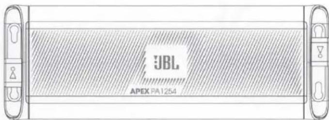
| Model | Apex PA1254 |
| Power Output | 2 x 50 W RMS |
| Frequency Response | 20 Hz - 20 kHz |
| Speaker Configuration | 2-way bass reflex |
| Supported Media | CD, CD-R/RW, MP3 |
| Radio Tuner | FM/AM with RDS |
| Inputs | Aux (3.5 mm), USB, Bluetooth |
| Outputs | Headphone jack, Speaker terminals |
| Dimensions (W x H x D) | 430 x 145 x 320 mm |
| Weight | 5.2 kg |
| Power Supply | AC 230 V, 50 Hz |
| Power Consumption | 60 W (standby <0.5 W) |
| Remote Control | Included |
| Display | LCD with backlight |
| Clock/Timer | Yes |
| Equalizer Presets | Rock, Pop, Jazz, Classic |
| Cleaning Instructions | Use a soft dry cloth; avoid liquids |
| Safety Certifications | CE, RoHS |
Frequently Asked Questions - Apex PA1254 JBL
User questions about Apex PA1254 JBL
0 question about this device. Answer the ones you know or ask your own.
Ask a new question about this device
Download the instructions for your Hi-Fi System in PDF format for free! Find your manual Apex PA1254 - JBL and take your electronic device back in hand. On this page are published all the documents necessary for the use of your device. Apex PA1254 by JBL.
USER MANUAL Apex PA1254 JBL
OWNER'S MANUAL

by HARMAN
THANK YOU FOR YOUR PURCHASE ...
Your product has been designed to provide you the performance and ease of operation you expect from JBL. Take time to read this manual before operating or installing your amplifier. This manual describes general installation guidelines and operation instructions. Please note that proper installation of mobile audio components requires qualified experience with mechanical and electrical procedures. If you do not have the knowledge and tools to perform this installation, we strongly recommend consulting an authorized JBL dealer about your installation options.
JBL APEX
TABLE OF CONTENTS
THANK YOU FOR YOUR PURCHASE ... 1
WHAT'S IN THE BOX 3
INSTALLATION AND WIRING 4
POWER AND GROUND CONNECTIONS 4
Power/Protect indicators 5
SIGNAL INPUT 5
SPEAKER OUTPUT CONNECTIONS 6
SETTING THE SOUND 11
Setting the input level 11
Crossover filters 11
SPECIFICATIONS 13
TROUBLESHOOTING 15
WHAT'S IN THE BOX
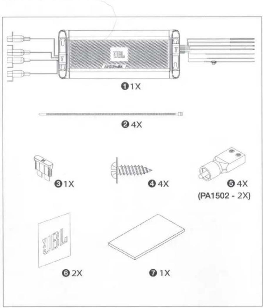
1 amplifier
② tie wraps
③ spare fuse
4 Stainless steel mounting hardware
⑤ high-level input adapters
6 JBL stickers
7 owner's manual
JBL APEX
INSTALLATION AND WIRING
IMPORTANT: Disconnect the vehicle's negative (−) battery terminal before beginning the installation.
- Wear protective eyewear when using tools.
- Choose a safe mounting location. Check clearances on both sides of the location. Be sure that screws will not puncture brake or fuel lines or wiring harnesses, and that wire routing will not interfere with vehicle operation. Use caution when drilling or cutting.
- When making electrical connections, make sure they are secure and properly insulated.
- Do not mount the amplifier with the heat sink facing downward, as this interferes with cooling.
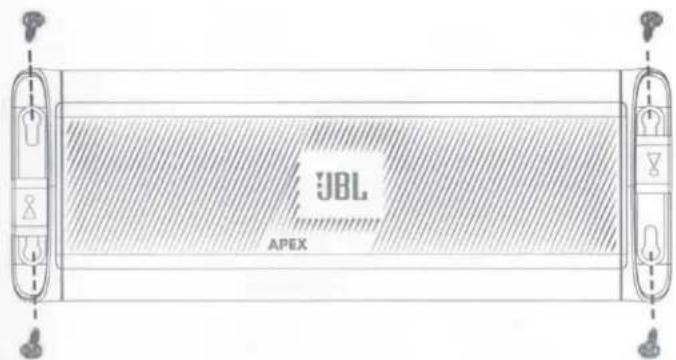
- Using the amplifier as a template, mark the locations of the holes on the mounting surface.
• Drill pilot holes in the mounting surface. - Attach the amplifier to the mounting surface with sheet metal screws (not included).
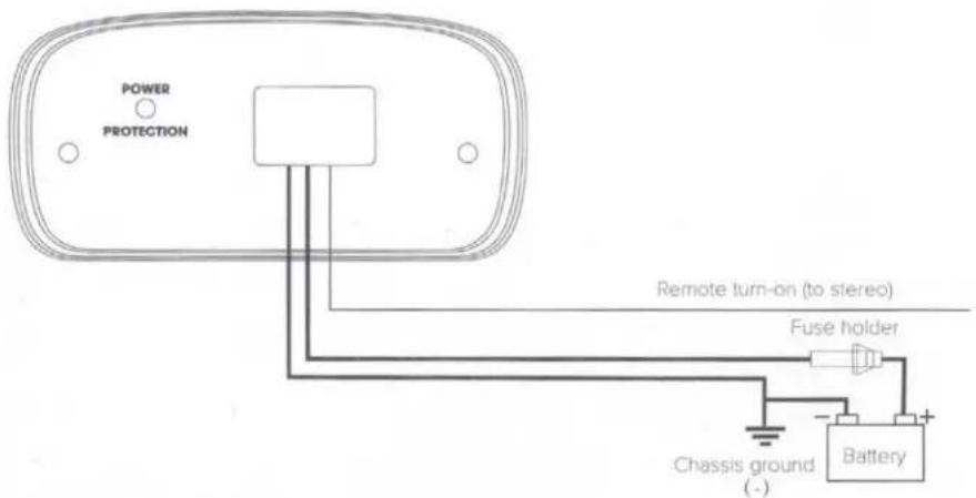
POWER AND GROUND CONNECTIONS
- Power: Connect the +12V power wire to the positive terminal of the vehicle's battery. Make sure the fuse and fuse holder are within 18" (457mm) of the battery.
- Ground: Connect the GND wire to the negative terminal of the vehicle's battery, or to the vehicle's chassis near the battery with a screw. NOTE: If possible, remove any paint from the chassis for best contact. It's recommended to use a star washer below the ring connector for a secure connection.
- Remote: Connect the remote turn-on wire to the "Remote Out" lead of the source unit, if using low-level signal inputs with an aftermarket stereo. NOTE: If you're using high-level signal inputs (your vehicle's speaker wires), the Apex amplifier's 12-volt DC offset feature will turn the amplifier on when it senses audio signal. In this case, you will not have to connect the remote turn-on wire and can tape or cap it off to prevent the introduction of noise.
Power/Protect indicators
The power light will illuminate in green when the amplifier is getting power and playing. The light will illuminate in red if the amp enters protect mode in the event of conditions such as over/under voltage, short circuit, amplifier output circuit failure, or excessive heat.
SIGNAL INPUT
- Line-level inputs: If your source unit offers preamp outputs, connect to the amplifier's L and R preamp inputs using RCA patch cables.
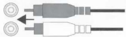
natural_image
Diagram of two connected audio/video cables with circular connectors (no text or symbols)- High-level inputs: If your audio system's source unit does not have line-level outputs, use the supplied high-level input adapters to connect to either the front or the rear speaker output wires of your source unit. Use solder, butt connectors, or your preferred splicing method. The 12-volt DC offset feature will turn the amplifier on when it senses signal.
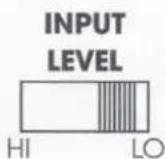
- Input level selection: If you're sending signal to the amplifier using low-level outputs from your source unit, slide the input level selector to "LO." If using high-level outputs from your source unit, slide the selector to "HI."
JBL APEX
SPEAKER OUTPUT CONNECTIONS
Connect your speakers to the amplifier's speaker output wires, observing proper polarity: connect each amplifier's positive (+) lead to the appropriate positive (+) speaker terminal, and negative (-) lead to the appropriate negative (-) speaker terminal. NOTE: Speaker-wire extensions might be necessary.
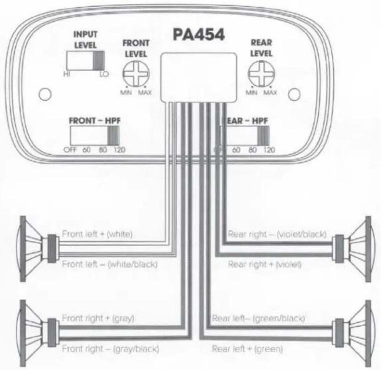
- PA454 4-channel operation: Connect the front left speaker leads (white and white/black) to the front left speaker's + and - terminals, and the front right speaker leads (gray and gray/black) to the front right speaker's + and - terminals. Next, connect the rear left speaker leads (green and green/black) to the rear left speaker's + and - terminals, and the rear right speaker leads (violet and violet/black) to the rear right speaker's + and - terminals.
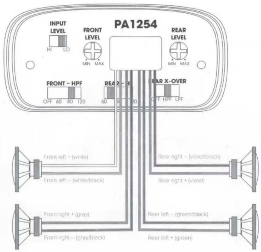
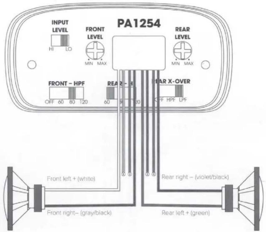
- PA1254 4-channel operation: Connect the front left speaker leads (white and white/black) to the front left speaker's + and - terminals, and the front right speaker leads (gray and gray/black) to the front right speaker's + and - terminals. Next, connect the rear left speaker leads (green and green/black) to the rear left speaker's + and - terminals, and the rear right speaker leads (violet and violet/black) to the rear right speaker's + and - terminals.
JBL APEX
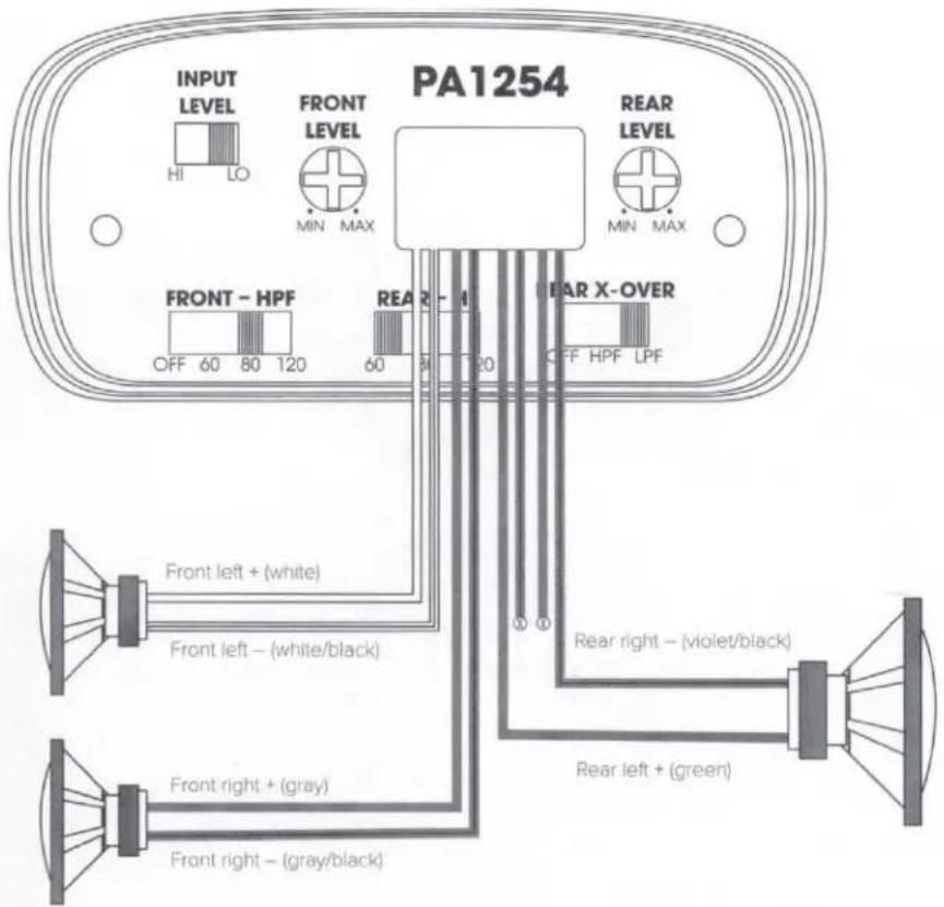
- PA1254 3-channel (bridged) operation: Connect the front left speaker leads (white and white/black) to the front left speaker's + and - terminals, and the front right speaker leads (gray and gray/black) to the front right speaker's + and - terminals. Next, connect the rear left + speaker lead (green) to the single speaker's + terminal, and the rear right - speaker lead (violet /black) to the single speaker's - terminal.
NOTE: To prevent electrical interference or short-circuiting, terminate the unused speaker leads with a wire cap or electrical tape.
- PA1254 2-channel (bridged) operation: Connect the front left + speaker lead (white) to the front single speaker's + terminal, and the front right - speaker lead (gray/black) to the front single speaker's - terminal. Next, connect the rear left + speaker lead (green) to the rear single speaker's + terminal, and the rear right - speaker lead (violet /black) to the rear single speaker's - terminal. NOTE: To prevent electrical interference or short-circuiting, terminate the unused speaker leads with a wire cap or electrical tape.
JBL APEX
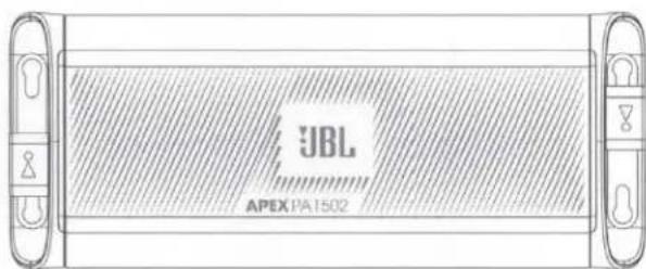
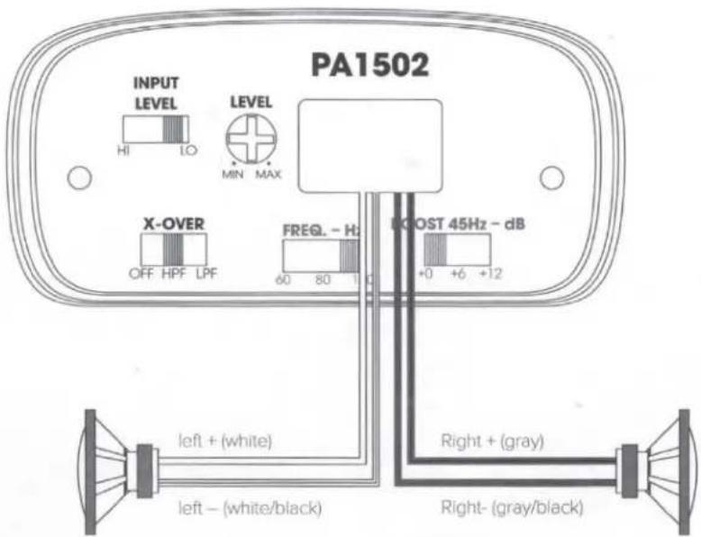
- PA1502 2-channel operation: Connect the left speaker leads (white and white/black) to the left speaker's + and - terminals, and the right speaker leads (gray and gray/black) to the right speaker's + and - terminals.
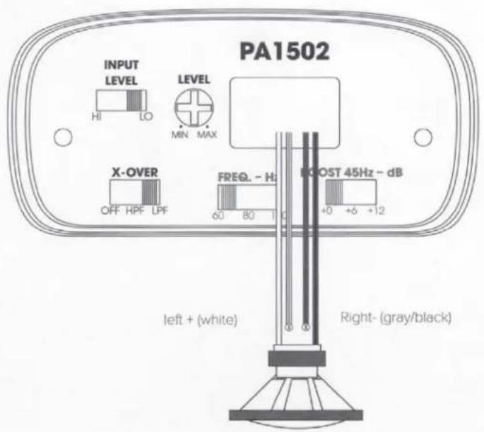
- PA1502 bridged operation: Connect the amplifier's left positive (+) wire (white) to the single speaker's + terminal, and the right negative (-) wire (gray/black) to the speaker's - terminal.
NOTE: To prevent electrical interference or short-circuiting, terminate the unused speaker leads with a wire cap or electrical tape.
SETTING THE SOUND
Setting the input level
To match your amplifier's input sensitivity (gain) to your source unit's output level, we recommend the following procedure:
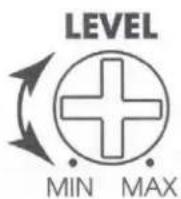
- Turn the input level control counterclockwise to MIN (minimum).
- Play a dynamic music track through your source unit. Turn the source unit's volume control to the 3/4 position.
- Turn the input level control dial clockwise towards MAX until you hear distortion in the music (it's no longer clear), then turn it counterclockwise until the music sounds clear again. Your input sensitivity is now set.
Crossover filters
You can adjust your Apex amplifier's filters to suit your listening preferences and speaker configuration.
The PA454 lets you select no filter (OFF) for a full-range signal, or engage a high-pass filter (HPF) on the front and rear channels, if you're powering speakers and have an independently powered subwoofer in your system. Slide the switch to choose your desired crossover point.
JBL APEX
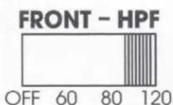
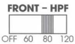
The PA1254 lets you select either no filter (OFF) for a full-range signal, or a high-pass filter (HPF) for your front channels if you're powering a subwoofer with the rear channels. Slide the switch to choose your desired crossover point.
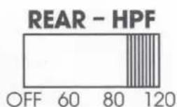
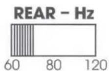
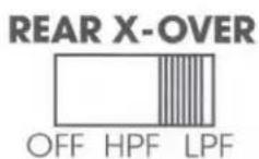
For the rear channels, you can select between no filter (OFF); a high-pass filter (HPF) if you're powering a subwoofer independently, or a low-pass filter (LPF) if you're using the rear channels to power a subwoofer in bridged mode. Slide the REAR – HZ switch to choose your desired crossover point.
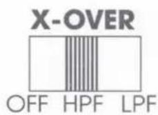
The PA1502 lets you slide the X-OVER switch to select no filter (OFF) for a full-range signal; a high-pass filter (HPF) if you're powering speakers and have an independently powered subwoofer in your system; or a low-pass filter (LPF) if you're powering a subwoofer in bridged mode. Slide the FREQ switch to choose your desired crossover point.
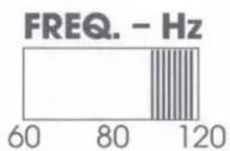
bar
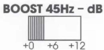
FREQ. - Hz | Frequency (Hz) | Value | | :--- | :--- | | 60 | 60 | | 80 | 80 | | 120 | 120 |The PA1502 also includes a bass boost (BOOST) switch for a +6dB or +12dB boost at 45 Hz.
SPECIFICATIONS
| Model | PA454 |
| Operating voltage: | 9V – 16V |
| RMS power @ 4 ohms: | 45W x 4 |
| RMS power @ 2 ohms: | N/A |
| RMS bridged power @ 4 ohms | N/A |
| Total peak power: | 450W |
| Fuse size: | 15A |
| High input maximum sensitivity: | 500mV – 15V |
| Line input maximum sensitivity: | 200mV – 6V |
| Signal-to-noise ratio (reference to 1 watt): | >75dB |
| THD + N at rated power: | <1% |
| Frequency response: | 20Hz -20KHz |
| Crossover filter | Selectable hi-pass filter: off, 60-, 80-, 120Hz @ 12dB/ octave |
| Bass boost | N/A |
| Amplifier Class | Class D |
| Turn-on Modes | 12V & DC offset |
| Recommended wire gauge | 10 AWG |
| Dimensions (H x W x D): | 8.25" (208.50mm) W x 1.75" (43.00mm) H x 3.3" (83.80mm) D |
| Weight | 2.4lbs (1.1kg) |
JBL APEX
| PA1254 | PA1502 |
| 9V – 16V | 9V – 16V |
| 75W x 4 | 100W x 2 |
| 125W x 4 | 150W x 2 |
| 250W x 2 | 300W x 1 |
| 1250W | 750W |
| 40A | 25A |
| 500mV – 15V | 500mV – 15V |
| 200mV – 6V | 200mV – 6V |
| >75dB | >75dB |
| <1% | <1% |
| 20Hz – 20kHz | 20Hz -20KHz |
| Front selectable hi-pass filter: off, 60-, 80-, 120Hz @ 12dB/octaveRear slectable all-/hi-/lo-pass filter: 60-, 80-, 120Hz @ 12dB/octave | Selectable all-/hi-/lo-pass filter: 60-, 80-, 120Hz @ 12dB/octave |
| N/A | 0, +6dB, +12dB selectable @45Hz (only when LPF is engaged) |
| Class D | Class D |
| 12V & DC offset | 12V & DC offset |
| 10 AWG | 10 AWG |
| 9.4" (238.50mm) W x 1.75" (43.00mm) H x 3.3" (83.80mm) D | 8.25" (208.50mm) W x 1.75" (43.00mm) H x 3.3" (83.80mm) D |
| 2.9lbs (1.3kg) | 2.4lbs (1.1kg) |
TROUBLESHOOTING
| PROBLEM | No audio and POWER INDICATOR is off. |
| CAUSE and SOLUTION | No voltage at BATT+ and/or REM terminals, or bad or no ground connection. Check voltages at amplifier terminals with VOM. |
| PROBLEM | No audio and PROTECT and POWER INDICATORS flash. |
| CAUSE and SOLUTION | Voltage less than 9V on BATT+ connection. Check vehicle charging system. |
| PROBLEM | No audio and PROTECT INDICATOR is on. |
| CAUSE and SOLUTION | Amplifier is overheated. Make sure amplifier cooling is not blocked at mounting location. Verify that speaker-system impedance is within specified limits. Or, there may be voltage greater than 16V (or less than 8.5V) on BATT+ connection. Check vehicle charging system. |
| PROBLEM | Amplifier fuse keeps blowing. |
| CAUSE and SOLUTION | The wiring is connected incorrectly or there is a short circuit. Review installation precautions and procedures. Check wiring connections. |
| PROBLEM | Distorted audio. |
| CAUSE and SOLUTION | Gain is not set properly. Check INPUT LEVEL setting. Check speaker wires for shorts or grounds. Amplifier or source unit may be defective. |
| PROBLEM | Distorted audio and PROTECT INDICATOR flashes. |
| CAUSE and SOLUTION | Short circuit in speaker or wire. Remove speaker leads one at a time to locate shorted speaker or wire, and repair. |
| PROBLEM | Music lacks dynamics or "punch." |
| CAUSE and SOLUTION | Speakers are not connected properly. Check speaker connections for proper polarity. |

HARMAN International Industries, Inc.
8500 Balboa Boulevard, Northridge, CA 91329 USA
www.jbl.com

Brand : JBL
Model : Apex PA1254
Category : Hi-Fi System