
4964110 - Tripod BRESSER - Free user manual and instructions
Find the device manual for free 4964110 BRESSER in PDF.


User questions about 4964110 BRESSER
0 question about this device. Answer the ones you know or ask your own.
Ask a new question about this device
Download the instructions for your Tripod in PDF format for free! Find your manual 4964110 - BRESSER and take your electronic device back in hand. On this page are published all the documents necessary for the use of your device. 4964110 by BRESSER.
USER MANUAL 4964110 BRESSER
Telscope Accessory ·
Photo Mount
EN
Instruction manual

Visit our website via the following QR Code or web link to find further information on this product or the available translations of these instructions.

1 Imprint 4
3 General Product Information.... 4
4 About this Instruction Manual.... 4
5 Intended use 4
6 General safety instructions .... 5
7 Parts overview and scope of delivery 6
8 Setting up the tripod 7
9 Attaching the polar wedge....8
10 Attaching the pole finder scope to the photo mount 8
11 Attaching the mount head to the polar wedge 9
12 Set up power supply for the tracking motor....9
13 Set the latitude (pole height) 9
14 Levelling the tripod 10
15 Attach the mount head onto a photo tripod.... 10
16 Attach the camera on the ball head.... 10
17 Using the pointfinder .... 10
18 Putting the pole finder illumination into operation 11
19 Focussing the Pole finder scope 11
20 Using the hand control 11
21 Finding the celestial pole.... 12
22 Use of the polar finder scope 13
23 First long time exposures.... 16
24 EC Declaration of Conformity 16
25 Warranty 16
26 Technical data.... 16
1 Imprint
Bresser GmbH
Gutenbergstr. 2
46414 Rhede
Germany
If you wish to submit a warranty claim or service request, please refer to the "Warranty" and "Service" information in this document. Please be aware that any requests or submissions sent directly to the manufacturer cannot be processed.
Errors excepted. Subject to technical modifications.
© 2018 Bresser GmbH
All rights reserved.
Reproduction of this document, including extracts, in any form (photocopied, printed etc.) or the use and distribution of this document by electronic means (image file, website etc.) is not permitted without the prior written consent of the manufacturer.
The terms and brand names of the respective companies used in this document are protected by brand, patent or product law in Germany, the European Union and/or other countries.
2 Validation
This document is valid for the products with the following part numbers:
4964110 4964111 4964112
Version of manual: v042018a
Name of manual: Manual_4964110-4964111-4964112_Photo-Mount_en_BRESSER_v042018a
Information is always provided for service requests.
3 General Product Information
The Photo Mount is available in different versions with correspondingly varying scope of delivery. Some sections in this manual may therefore refer to components that are not included in all product variants, but are optionally available.
4 About this Instruction Manual

NOTICE
These operating instructions are to be considered a component of the device.
Please read the safety instructions and the operating instructions carefully before use.
Keep these instructions for renewed use at a later date. When the device is sold or given to someone else, the instruction manual must be provided to the new owner/user of the product.
5 Intended use
- This device is not intended to be used by persons (including children) with limited physical, sensory or mental capabilities or those who lack the relevant experience and/or knowledge, unless they are supervised by a person responsible for their safety or have received instructions from this person as to how the device is used.
• This device is for private use only.
• The device is for indoor use only.
6 General safety instructions

DANGER
Danger of blindness!
Never use this device to look directly at the sun or in the direct proximity of the sun. There is a risk of BLINDNESS!

! DANGER
Risk of suffocation
Improper use of this product can result in suffocation. This is particularly dangerous for children. The following safety information must be observed at all times.
- Keep packaging materials (plastic bags, rubber bands etc.) away from children. They can cause suffocation.
• This product contains small parts that could be swallowed by children. There is a risk of choking!

CAUTION
Fire hazard!
In case of any improper use of this device, there is a risk of fire. Therefore please read the safety instructions below to avoid the initiation of burning.
- Do not place the device, particularly the lenses, in direct sunlight. The concentration of light could cause a fire.

NOTICE
Risk of damage to property
Improper handling can result in damage to the device and/or to the accessories. Always observe the following safety information when using the device.
- Do not disassemble the device. In the event of a defect, please contact the Service Centre in your country (see chapter 'Service').
- Protect the device from severe shocks!
- Do not expose the components to direct sunlight for a longer time.
- Do not expose this device to higher temperatures and protect it from water and high humidity.

NOTICE
Privacy protection
Please heed the privacy of other people. Do not use this device to look into apartments, for example!
7 Parts overview and scope of delivery
text_image
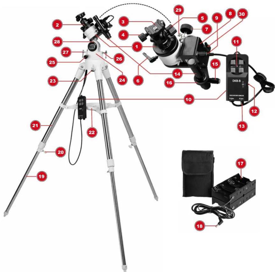
Labeled diagram of a scientific instrument setup with numbered parts for identification and assembly reference.Illustration 1: Photo mount on polar wedge with tripod (Art. No. 4964110)
1 Photo mount 2 Ball head
3 Quick release plate 4 Fixing screw (quick release plate)
5 Fixing screw (ball joint) 6 Clamping lever (RA axis)
7 Rotary knob (RA axis) 8 RA axis motor
9 8-pin socket 10 Manual motion control
11 Speed buttons 12 North/South switch
13 DC connection socket for coaxial/barrel connector 14 Pole finder scope
15 Pole finder illumination 16 Pole finder holder
17 Battery compartment (6V DC) 18 DC coaxial/barrel connector
19 Inner tripod leg 20 Clamping screw (tripod leg)
21 Outer tripod leg 22 Accessory tray
23 Central screw 24 Circular level
25 Fixing screw (pole wedge) 26 Long toggle screw
27 Short toggle screw (polar height) 28 Polar wedge element
29 Coupling (trcking motor) 30 Pointfinder
Depending on the product variant, different accessories are included with the purchase. The image shows the complete delivery content.
Scope of delivery (4964110)
Photo mount; ball-head; tracking motor; controller with connecting cables; pole finder scope with illumination unit; battery pack with connecting cable and storage bag; tripod for photo mount; accessory tray; polar wedge (possibly pre-assembled on the tripod); 2 pcs. toggle screws (polar height); 2 pcs. thumbscrews (azimuth); 1 pc. central screw M10 (polar wedge); 2 pcs. 1/4" photo adapter thread screw; assembling tools
Scope of delivery (4964111)
Photo mount; ball-head; tracking motor; controller with connecting cables; Pole finder scope with illumination unit; battery pack with connecting cable and storage bag; assembling tools
Scope of delivery (4964112)
Tripod for photo mount; accessory tray; polar wedge (possibly pre-assembled on the tripod); 2 pcs. toggle screws (polar height); 2 pcs. thumbscrews (azimuth); 1 pc. central screw M10 (polar wedge); assembling tools
Additionally needed (4964110 + 4964111, not included):
8 pcs. 1.5V D type batteries
NOTICE! The power supply for the mount is 6V. The use of 8 pcs. 1.5V D type batteries only serves for a longer operation time!
8 Setting up the tripod
natural_image
Close-up of a hand adjusting a tripod-mounted camera mount (no visible text or symbols)
natural_image
Close-up of a person's hand using a mechanical device on a tripod (no visible text or symbols)NOTICE! This section covers the photo mount assembly on the specially designed tripod with polar wedge. If the photo mount is to be mounted on an existing tripod, also read the corresponding instructions.
CAUTION! Carefully take the tripod out of the packaging with its legs pointing parallel to the ground. The inner tripod legs are not screwed in and can slip out!
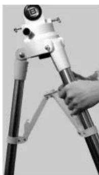
NOTICE! The tripod legs are pre-assembled and already connected to the tripod head and the cross struts.
- After unpacking quickly set up the tripod with the tripod feet facing down.
- Grasp two of the three tripod legs and slowly pull them out until the cross stuts are fully extended. The entire weight of the tripod weighs on the third leg.
- Pull out the tripod legs to the desired height. Make sure that the bubble of the circular level is in the middle of the circle to ensure a horizontal plane stand. If necessary, re-adjust the tripod legs.
- Hand-tighten the clamping screws for the tripod legs.
CAUTION! Do not overtighten the clamping screws to avoid damage!
-
Place the accessory tray on the center of the cross stuts and with its flat side facing down. Tighten it by turning it clockwise at about 60°. The three "noses" of the accessory tray must grip into the retaining clips and lock.
-
Check the stand of the tripod. It has to be straight and level.
9 Attaching the polar wedge
NOTICE! This section covers the photo mount assembly on the specially designed tripod with polar wedge. If the photo mount is to be mounted on an existing tripod, also read the corresponding instructions.
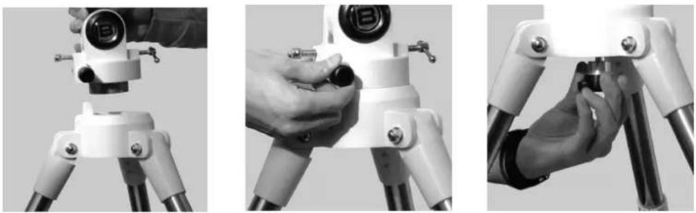
- Screw in the azimuth adjusting screws approx. half way.
- Insert the polar wedge in the tripod head.
NOTICE! Make sure that the 'nose' for the azimuth adjusting screws reaches the polar wedge.
- With the central screw fasten the polar wedge on the tripod head.
- Tighten the azimuth adjusting screws evenly.
- Insert the two toggle screws for the pole height adjustment into the polar wedge.
NOTICE! The short toggle screw will be mounted near the azimuth adjusting screws and the long toggle screw will be mounted opposite.
10 Attaching the pole finder scope to the photo mount
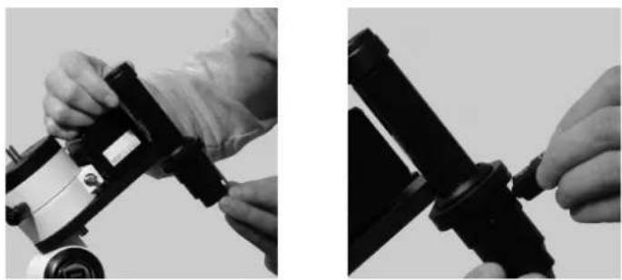
- Remove the three small fixing screws from the pole finder holder.
- Turn the pole finder illumination unit anti-clockwise and remove it completely from the pole finder.
- Use the pole finder holder and the three fixing screws to attach the pole finder scope to the mount's base plate.
- Evenly tighten the three fastening screws so that the pole finder scope can still be turned inside the holder with some resistance.
- Insert the pole finder illumination unit in the pole finder scope.
11 Attaching the mount head to the polar wedge
natural_image
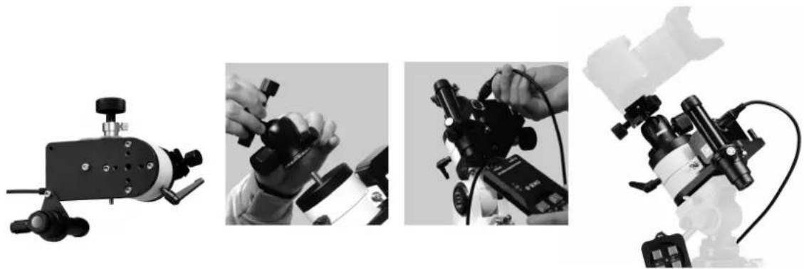
Four-panel black-and-white photo collage showing mechanical devices and control panels (no visible text or symbols)NOTICE! This section covers the photo mount assembly on the specially designed tripod with polar wedge. If the photo mount is to be mounted on an existing tripod, also read the corresponding instructions.
- Attach the mount head onto the polar wedge using the supplied two 14 "screws supplied and the hexagon socket wrench.
NOTICE! Pay attention to the correct orientation of the mount head when attaching it!
- Thighten the supplied ball head with the 3/8" photo thread onto the upright threaded screw.
12 Set up power supply for the tracking motor.
- Insert the batteries into the battery compartment. Ensure that the battery polarity (+/-) is correct.
NOTICE! Instead of using the battery box, the controller can also be operated with a standard power adapter or battery pack. Pay attention to the correct polarity of the connector (indicated on the hand box) and a constant DC voltage of 6V!
-
Put the DC coaxial/barrel connector into the DC socket of the controller.
-
Put the motor connecting cable into the 9-pin socket of the motor.
natural_image
Close-up of a mechanical optical instrument with a dial and adjustable lever (no visible text or symbols)NOTICE! This section covers the photo mount assembly on the specially designed tripod with polar wedge. If the photo mount is to be mounted on an existing tripod, also read the corresponding instructions.
Before attaching the camera and setting the exact orientation on Polaris, it is recommended to set the latitude roughly through the scale of the polar wedge:
- Adjust the polar height by turning the toggle screws until the triangular pointer is above the desired value of the mount's latitude scale.
NOTICE! Determine the latitude of your observation point using the information in the section "Width table", or search the Internet for the appropriate information for your location. Turn the adjusting screws until the pointer indicates the desired latitude. The adjusting screws operate through an adjustment and counter mechanism (that means: before you fix one, loosen the other one).
- As soon as the pointer indicates the desired latitude, tighten the two screws so that they reach the mount.
14 Levelling the tripod
-
Position the tripod so that the tripod leg, which is near the azimuth adjustment screws, points north.
-
Slightly loosen the clamping screws of a tripod leg and adjust the leg until the bubble of the circular level in the tripod head is within the circle mark.
15 Attach the mount head onto a photo tripod
NOTICE! This section covers the photo mount assembly on a normal photo tripod with 1/4" or 3/8" thread screw. If attaching the photo mount on an existing photo tripod, also read the corresponding instructions.
-
Fix the mount head with the appropriate fine thread at the bottom of the mounting plate onto the fine thread screw of the tripod.
-
Thighten the supplied ball head with the 3/8" photo thread onto the upright threaded screw.
16 Attach the camera on the ball head
-
Loosen the fixing screw at the ball-head.
-
Press the locking pin on the tripod head and at the same time push the quick release plate sideways out of the guide.
CAUTION! Always ensure that the quick release plate and the camera are securely mounted in the following steps. Otherwise, the camera could break loose and fall down. The manufacturer is not liable for material damage caused by improper handling.
-
Use the recessed 14 " thread screw to attach the quick release plate to the camera body or to the tube clamp of the lens.
-
Slide the quick release plate with the mounted camera into the guide of the ball-head and tighten the fixing screw again.
CAUTION! Make that the quick-release plate will not jam when inserting it and therefore will jump out of the guide. This could cause damage to the camera as a result.
NOTICE! The manufacturer is not liable for any damage caused by improper handling!
17 Using the pointfinder
A small pointfinder is placed on the opposite to the illuminated pole finder scope.
It serves for a faster, coarse pole alignment. This orientation method is best for shootings with a short exposure time. For long exposures, the more complex alignment by means of the polae finder scope is absolutely necessary.
18 Putting the pole finder illumination into operation
text_image
Diagram of a mechanical assembly with numbered components, likely a valve or connector assembly.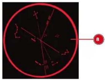
text_image
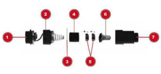
Diagram showing a red circular object with internal lines and a labeled point 'B' pointing to it.Illustration 2: Parts of the pole finder illumination
1 On/Off rotary switch 2 Threaded cap
3 Plastic plate 4 Battery holder
5 Batteries 6 LED
7 Threaded socket 8 Illuminated engraving plate (pole finder)
NOTICE! The pole finder illumination is operated with two type LR41 batteries. Depending on the model, batteries may already be included.
CAUTION! Do not unscrew the on / off rotary switch from the battery compartment cover! Both parts are firmly connected by a cable, which could be damaged when unscrewing it.
First use
- Remove the battery compartment cover, together with the on / off rotary switch.
- Remove the plastic plate (insulation) used to protect against discharging between the battery compartment cover and the batteries.
OR
Battery replacement:
- Remove the battery compartment cover, together with the on / off rotary switch.
- Insert batteries into the battery holder according to the correct polarity.
- Insert the battery holder into the battery compartment.
- Screw in the pole finder illumination into the pole finder scope.
- Switch on or off the illumination via the on/off rotary switch.
19 Focussing the Pole finder scope
NOTICE! The focussing of the pole finder scope can be done before installation.
Look at an observing object at a distance of 100m. If the image is not sharp, turn the eyepiece until the image is sharp.
20 Using the hand control
- Slide the side switch of the hand controller to "N" position for the use in the Northern Hemisphere or switch it to "S" position for the Southern Hemisphere. The RA motor is switched on, the tracking starts automatically.
- If necessary, make corrections to the tracking speed / direction using the direction keys as indicated on the keyboard.
NOTICE! The stepper motor heats up during prolonged operation; this is normal and not a malfunction.
21 Finding the celestial pole
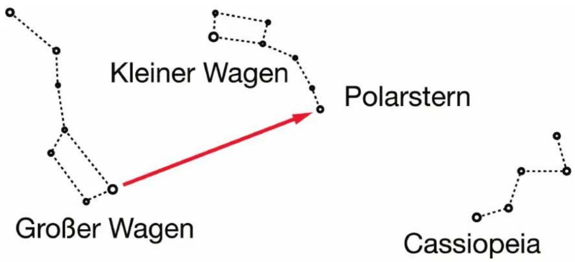
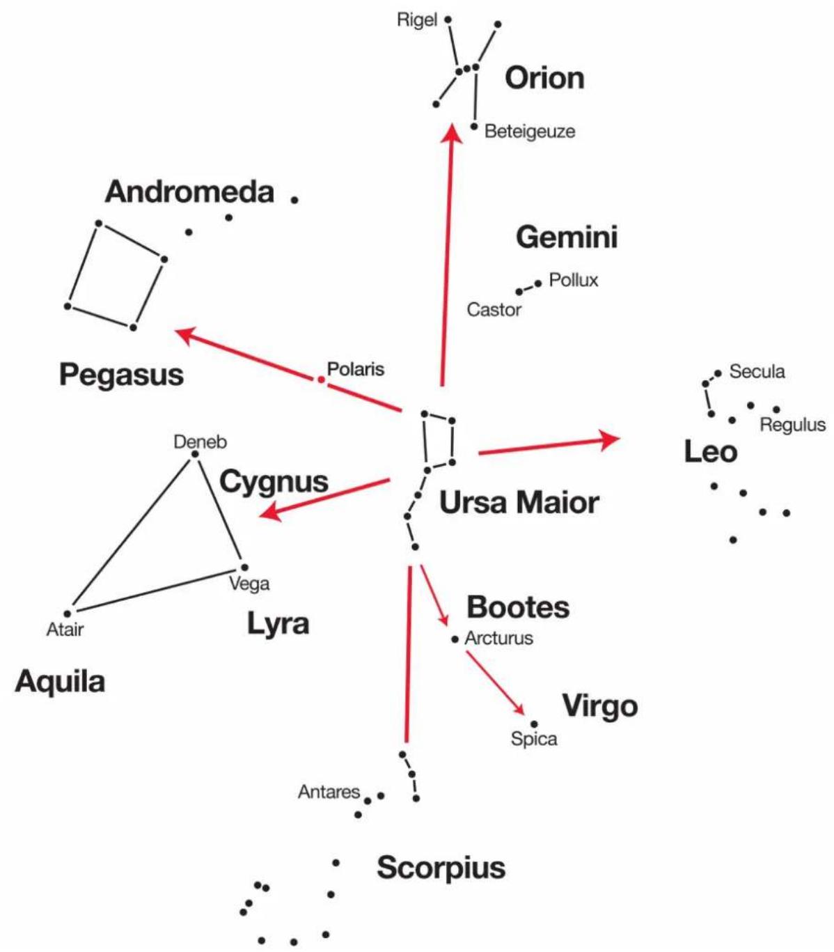
To get a rough idea of where the points of the compass are at an observing place, you should be aware of the directions where the sun rises each day (east) and goes down (west). After it has become dark at your observation point, turn to north - this can be achieved by pointing with your left shoulder to the direction where the sun has just set. To find exactly the pole, you should now locate Polaris - use the Big Dipper as a signpost (see picture). For an exact tracking of astronomical objects, you should aim your telescope at the celestial pole.
Search maps to find Polaris
flowchart
graph TD
    A["Großer Wagen"] --> B["Kleiner Wagen"]
    B --> C["Polarstern"]
    C --> D["Cassiopeia"]
    style A fill:#f9f,stroke:#333
    style B fill:#ccf,stroke:#333
    style C fill:#cfc,stroke:#333
    style D fill:#fcc,stroke:#333
flowchart
graph TD
    A["Andromeda"] --> B["Pegasus"]
    B --> C["Polaris"]
    C --> D["Ursa Maior"]
    D --> E["Gemini"]
    E --> F["Pollux"]
    D --> G["Leo"]
    G --> H["Regulus"]
    D --> I["Aquila"]
    I --> J["Aquila"]
    D --> K["Lyra"]
    K --> L["Cygnus"]
    L --> M["Deneb"]
    M --> N["Vega"]
    N --> O["Antares"]
    O --> P["Scorpius"]
    D --> Q["Bootes"]
    Q --> R["Arcturus"]
    R --> S["Virgo"]
    S --> T["Spica"]
    T --> U["Antares"]
    U --> V["Scorpius"]
    D --> W["Rigel"]
    W --> X["Orion"]
    X --> Y["Beteigeuze"]
22 Use of the polar finder scope
Orient yourself towards the sky. To align your mount to the celestial pole with the help of your polar finder scope, you need unobstructed view towards the northern part of the sky (or to the south, if you are using the telescope in the southern hemisphere, such as Australia).
The following procedure applies to aligning the mount for the use on the northern hemisphere, such as Europe or North America. Look for the constellation „Big Dipper“. The Big Dipper represents a part of the constellation „Big Bear (Ursa Major)“. Depending on the season you can see the constellation at different locations at dusk: in the winter it can be seen just above the northern horizon, in spring halfway up in the north east, in the summer almost directly above in the north, and in the autumn in the north west. The following figure shows the northern part of the sky at dusk at the beginning of January:

text_image
Polaris Dyaco Urse Minor Camelopardalis Capella Uce Major Lynx Canes Vaneboi Léo Minor Geotex Arcturus Come BerenicesIllustration 3: Sky view: Big Dipper in the constellation Big Bear (Ursa Major)
The Big Dipper / Big Bear is located in the north, near the horizon. We can see the three stars of the Big Dipper's handle on the left and the car body with the brightest star Dubhe on the top right. The "rear" stars in the car body are needed to get to the north star (Polaris). We marked them yellow and big. If you extend the connecting line of the two rear stars in the car body, you will come to the brightest star in the constellation Little Dipper (Ursa Minor). This is Polaris.
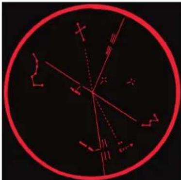
The North Star may be located in the immediate vicinity of the north celestial pole, but it is not located directly at the pole. For this reason it does circle the pole during the day/year like any other stars that circle the celestial pole. We now have to find out on which position on this circle the star is located at this very moment. For this, let us refer to following figure:
natural_image
Circular diagram with red lines and symbols on black background, no readable text or labelsIllustration 4: Polar finder scope engraving plate with Big Dipper (left).
The figure shows the engraving plate of the polar finder scope. You may notice three figures with little circles that are connected with lines. These symbols represent constellations. To align the photo mount onto the north celestial pole we need the constellation in the upper left and the constellation below the middle at the right. You may have recognized the left constellation already – it is the Big Dipper, that we already located successfully.
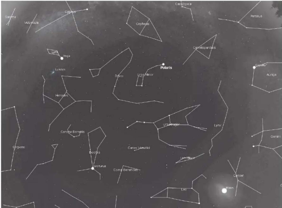
The other constellation is Cassiopeia which we have to locate now. To do this, let us have a look onto the next figure, which is simply showing a bigger part of the sky then the figure above:
text_image
Sacra Vulpaula Cypeta Cephes Casabopela Perseus Lyra Vega Cameloparadis Lynix Polaris Dunco Ursa Minor Hercules Corona Borealis Serpens Boodes Arcturus Coma Beranites Lao Lam Minor Canes Venatibi Lynx Gemini Cancer MoonIllustration 5: Enhanced part of the sky view.
We recognize the Big Dipper at the lower part in the middle of the field of view, the North Star almost in the middle oft he picture and a constellation at the upper end of the picture just slightly to the right of the middle. This constellation looks like a W turned upside down - Cassiopeia. Three stars have been marked in the three constellations which form a line:
- Alkaid - the first star in the Big Dippers handle
- Polaris
- Epsilon Cassiopeia - the star at the lower right in the constellation Cassiopeia
CAUTION! Loosen the coupling of the tracking motor before moving the right ascension axis (RA) manually. Otherwise the tracking motor may be damaged! To do this, turn the small knurled screw on the coupling approximately one turn counterclockwise.
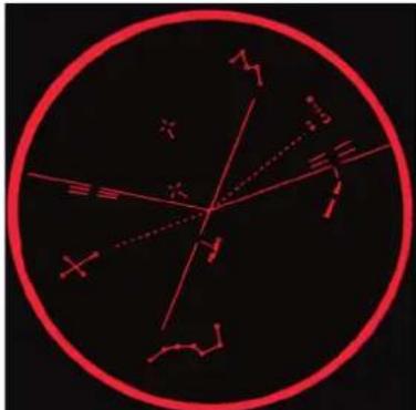
Move the right ascension axis of the photo mount until the line in the recticle aligns with the orientation of the corresponding line at the sky.
text_image
Diagram showing a red circle with intersecting lines and symbols, possibly representing a geometric or physical concept.Illustration 6: Polar finder scope engraving plate with Big Dipper (bottom) and rotated RA axis. Notice the difference to the image of the engraving plate before:
The position oft he constellation symbols in the recticle now aligns with the orientation of the real constellations at the sky. Lock the RA-axis.
Now move the mount with the adjustment knobs for azimut and altitude until Polaris is positioned at the right place in the line in the recticle – we have already marked this position for you with a white dot star. Your mount is now aligned to the Northern Celestial Pole.
Aligning the mount to the Southern Celestial Pole is analogous to the alignment described above. The constellations that help us orient the recticle are the Southern Cross (or, more precisely its brightest star, Acrux) and the brightest star in the constellation Eridanus (Achenar). The star that has to be positioned into the right place in the recticle is Polaris Australis (Sigma Octans).
23 First long time exposures
The photo mount is designed to use a camera with lens of max. 2.5 kg total weight to carry and track. All cameras with 1/4" (6.3mm) tripod connection thread and the settings option Bulb "B" for long time exposure are basically suitable for astrophotography with this mount. Ideal for the beginning are high-speed wide-angle lenses, because with increasing focal length and exposure time the tracking accuracy also increases. With a wide-angle lens, the exposure time can be exposed up to several minutes without any problems and the stars remain punctiform. For example: with an 200mm telephoto lens, a precise polar alignment of the photo mount is needed.
NOTICE! For almost all photos with wide-angle lenses and exposure times of up to 120 seconds, approximate settings of latitude and pole axis are sufficient. Do not spend too much time aligning the photo mount on the celestial pole as perfectly as possible! With increasing focal length and exposure time, however, a precise polar alignment is essential. Otherwise the stars blur to trace tracks.
Typical achievable exposure times with good tracking accuracy:
- 160mm to 35mm wide-angle lens: 10 minutes (600 sec.)
• 200mm telephoto lens: 5 minutes (300 sec.)
24 EC Declaration of Conformity

Bresser GmbH has issued a "Declaration of Conformity" in accordance with applicable guidelines and corresponding standards. This can be viewed any time upon request. http://www.bresser.de • info@bresser.de
25 Warranty
The regular guarantee period is 2 years and begins on the day of purchase. To benefit from an extended voluntary guarantee period as stated on the gift box, registration on our website is required.
You can consult the full guarantee terms as well as information on extending the guarantee period and details of our services at www.bresser.de/warranty_terms.
26 Technical data
| Feature 4964110 | Photo mount with tri-pod and polar wedge | 4964111 Photo mount without tripod and polar wedge | 4964112 Tripod and polar wedge without photo mount |
| Parallactic photo mount included included optional | |||
| Height-adjustable tripod made of stainless steel with polar wedge and circular level | included optional included | ||
| Automatic compensation of the earth's rotation | yes yes -/- | ||
| Hand control with tracking motor (2x/32x) | included included -/- | ||
| Switchable for northern or southern hemisphere | yes yes -/- | ||
| Optical polar finder scope with polar finder illumination | included included -/- | ||
| Ball-head with quick release plate for camera mounting | yes, plate with 1/4" photo thread | yes, plate with 1/4" photo thread | -/- |
| Fixture for ball-head mounting | yes, with 3/8" threaded bolt | yes, with 3/8" threaded bolt | -/- |
| Fixture for tripod mounting | yes, with 1/4" or 3/8" inner thread | yes, with 1/4" or 3/8" inner thread | -/- |
| Stepper motor tracking with worm-gear | yes yes -/. | ||
| Large Tommy screws and thumb screws for an easy use | yes -/- yes | ||
| Battery operation/ Mains operation | Yes, battery compartment ^1 included / optional ^2 | Yes, battery compartment ^1 included / optional ^2 | -/- |
| Operating time in battery mode | up to 50 hours up to 50 hours -/- | ||
| Power supply 6V DC, 5.5 / 2.5 mm socket (positive pole inside) | 6V DC, 5.5 / 2.5 mm socket (positive pole inside) | -/- | |
| Total weight 4.5 kg 1.0 kg 3.5 kg | |||
| Carrying capacity of the photo mount | 2.5 kg 2.5 kg -/- | ||
| Camera working height 140 cm max. -/- 140 cm max. | |||
Table 1: Model variants of the photo mount
1) Batteries not included or depending on model
2) suitable DC power adapter additionally needed (not included)
Service
DE AT CH BE
Please contact the service centre first for any questions regarding the product or claims, preferably by e-mail.
e-mail: service@bresseruk.com
Telephone*: +44 1342 837 098
Bresser UK Ltd
Customer Service Explore Scientific
Unit 1 starborough Farm,
Starborough Road, Nr Marsh Green,
Edenbridge, Kent TN8 5RB
Great Britain
* Number charged at local rates in the UK (the amount you will be charged per phone call will depend on the tariff of your phone provider); calls from abroad will involve higher costs.