
RWM165 - Smoke detector ABUS - Free user manual and instructions
Find the device manual for free RWM165 ABUS in PDF.


| Product type | Interconnected optical smoke detector |
| Brand | ABUS |
| Model | RWM165 |
| Dimensions | Height 36 mm, Diameter 102 mm |
| Power supply | Sealed 3 V lithium battery, service life up to 10 years |
| Detection technology | Photoelectric |
| Sound pressure | Greater than 85 dB(A) at 3 m |
| Coverage area | Up to 40 m² per device |
| Radio range | At least 100 m between detectors |
| Maximum number in network | 12 detectors |
| Operating temperature | 0 °C to 45 °C |
| Relative humidity | 10 % to 90 % (non-condensing) |
| Radio frequency | 868 MHz |
| Maximum transmission power | 10 dBm |
| Standards | EN14604-2005/AC-2008, VdS 3131, VdS 3515 |
| Main functions | Pulsed audible alarm, temporary silence (11 min), alarm memory, self-diagnosis, function test |
| Maintenance and cleaning | Dust removal by vacuuming or blowing, cleaning with a damp cloth (no water inside) |
| Safety | Do not paint, do not open, do not expose to water, storage temperature -10 to 60 °C |
| Spare parts | Non-replaceable integrated battery – no user maintenance |
| Repairability | Not user-repairable – replace the device at end of life |
| Service life | 10 years + 6 months after production date |
| Installation | Ceiling only, at least 50 cm from walls and obstacles |
| Use | Indoor use only, enclosed rooms |
| Warranty | Warranty on material and manufacturing defects (see manual) |
Frequently Asked Questions - RWM165 ABUS
User questions about RWM165 ABUS
0 question about this device. Answer the ones you know or ask your own.
Ask a new question about this device
Download the instructions for your Smoke detector in PDF format for free! Find your manual RWM165 - ABUS and take your electronic device back in hand. On this page are published all the documents necessary for the use of your device. RWM165 by ABUS.
USER MANUAL RWM165 ABUS
Security Tech Germany
natural_image
Line drawing of a circular mechanical component with internal grooves and mounting holes (no text or symbols)natural_image
Diagram of a circular device with ventilation grilles and a labeled component (no text or symbols)
natural_image
Diagram of a circular device with ventilation grilles and a labeled component (no text or symbols)
Wireless smoke alarm device

Security Tech Germany

natural_image
Line drawing of a circular device with ventilation grilles and a lid (no text or symbols)User manual
Wireless smoke alarm device
GB

20165.0786-19-21615 EN:1634-200516-2038

02/2016

Follow the Instructions to ensure proper operation! Smoke detectors help save lives!
Please keep save this instruction for use!
Contents
Introduction 27
Scope of delivery 28
Safety informations 29
Technical data 30
Functions and technical features 31
Emergency procedure when alarm sounds 31
Choosing a location 32
Networking 36
Installation and operation ....38
Test 40
Display and functions 41
Care and maintenance 45
Warranty 46
Disposal 47
Declaration of Performance 47
Declaration of Conformity....47
Notes to accompany user manual
Dear customer,
We are delighted that you have chosen our product and thank you for your trust. You have made a good choice. This smoke alarm device was developed and manufactured with great care in order to help draw your attention to any fire risk in good time. Please read this user manual thoroughly and observe all the instructions provided, as this will enable best use of the device. This manual serves as the fitting and maintenance instructions.
Introduction
Intended use
The device should only be used for its originally intended purpose! The product is not intended for any other use! This device may only be used for the following purpose(s):
- Detecting and raising the alarm of household fires or for similar applications in the living areas
Limitation of liability
Your rights are limited to the repair or replacement of this product in the same condition that it was delivered. ABUS accepts no liability for any special, incidentally arising or consequential damage, including, but not limited to, loss of revenue, loss of profit, restrictions in use of the software, loss or recovery of data, costs for replacement facilities, down times, damage to property and claims by third parties, including those arising from contractual or legal claims for recovery or those arising under damage legislation, notwithstanding other restricted or legally implicit warranty provisions or in cases where the limited warranty is not valid, the scope of liability of ABUS is limited to the purchase price of the product.
Introduction | Scope of delivery

| Item Name Comment | ||
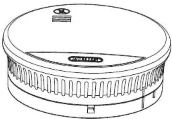
| 1 | Sound outlet opening | |
| 2 | Control light (LED) | The control light is located under the lid and shines through it. |
| 3 | Test/stop button | The test/stop button is activated by pressing the lower segment of the cover. |
| 4 | Detector base with mounting holes | |
| 5 | Smoke inlet opening | |
Packaging

- Remove all packaging before using device.
Scope of delivery
• ABUS smoke alarm device including built-in battery
- Operating instructions
• Installation equipment
Safety information
Safety information
The following symbols are used in this manual and on your device:
| Symbol | Signal word | Meaning | |
 | Danger | Warning message regarding risk of injury or health risk. | |
 | Important | Safety note on possible damage to the device / accessories | |
| [3SYW] | Note | Note regarding important information. | |
 | Danger | Small parts can be swallowed by children! | |
 | Warning | Use hearing protection when testing the wire- less smoke detector! | |
Battery recommendations
This product contains a built-in lithium battery. Built-in batteries may only be replaced or removed by qualified personnel. Do not use the product in environments where there is a risk of explosion, e.g. from flammable liquids, gases or dust. Never burn the product! The battery may explode in the fire. This would also release toxic substances. Do not store or use the product in areas where the temperature may fall below 0°C or exceed +40°C. Do not expose the product to direct sunlight for long periods of time.
Functions
To ensure correct operation of device, please observe the following points:
- Do not cover the device!
- Do not paint or cover device with wallpaper!
- Do not open or attempt to repair the device under any circumstances.
Technical data
Non-observance of the above points will render the guarantee void.
- The device is rendered unsuitable for use once it has been dropped or any other damage has been suffered.
Technical data
| Power supply DC 3 V Lithium Battery (built-in) | |
| Smoke detection photoelectric reflection | |
| Visual operating display LED flashes approx. every 6 minute | |
| Electric consumption 9,8 mA (ø standby) || 80 mA (ø alarm) | |
| Operating temperature 0° to 45°C | |
| Storage temperature -10° to 60°C | |
| Air humidity 10 % to 90 % (non-condensing) | |
| Sound pressure > 85 dB (A)@3 m | |
| Alarm mute mode ca. 11 minutes | |
| Detection range max. 40 m^2 within a single room | |
| Installation location ceiling (Internal rooms only) | |
| Wireless frequency 868 Mhz | |
| Wireless range | at least 100 m |
| Networking | Up to 12 detectors |
| Battery service life | Up to 10 years |
| Dimension | Height 36 mm, Diameter 102 mm |
| Maximum transmission power | 10 dBm |
| Applied standards | EN14604, VdS 3131, VdS 3515 |
Functions and technical features
Emergency procedure when alarm sounds
Functions and technical features
• The smoke alarm does not detect gases, vapours, heat and fire/flames!
- It is possible that people with limited hearing may not hear the alarm! For such cases special alarms with optical signalling are available.
- Especially high electromagnetic radiation may affect unit operation. Therefore, do not install the alarm near devices which emit electromagnetic radiation or close to magnets.
- This smoke alarm works according to the principles of optics (photoelectric reflection) and contains a measuring chamber in which penetrating smoke particles are measured.
- If the alarm threshold is exceeded, a loud, audible alarm will sound.
- The alarm will switch itself off as soon as the measuring chamber becomes smokefree again.
Emergency procedure when alarm sounds

(1) Alert all co-residents.
(2) Offer assistance to children, disabled and elderly people and invalids.
(3) Close all windows and doors behind you.
(4) Leave the building immediately.
(5) Do not use the elevators.
(6) Alert the fire service: tel. 112
Choosing a location
Choosing a location

flowchart
graph TD
    A["Attic"] --> B["Office"]
    A --> C["Bedroom"]
    A --> D["Living room"]
    A --> E["Cellar"]
    B --> F["Work room / workshop"]
    C --> G["Work room"]
    D --> H["Work room"]
    E --> I["Work room"]
    style A fill:#f9f,stroke:#333
    style B fill:#ccf,stroke:#333
    style C fill:#cfc,stroke:#333
    style D fill:#fcc,stroke:#333
    style E fill:#cff,stroke:#333
DG DG EG

Smoke alarms should be regarded as a minimum level of equipment in all sleeping rooms, children's rooms and corridors or passages used as escape routes; one alarm should be fitted in the centre of each room, always on the ceiling (no wall mounting).
Select the highest point in the room for mounting, with a minimum distance of 50 cm from any wall, furniture or lamps. Your installation is optimised by also installing the devices in all other rooms as well as on all landings. Please observe the illustrations in this manual!
Choosing a location
Special case: installation in a hallway with a width of < 3 m
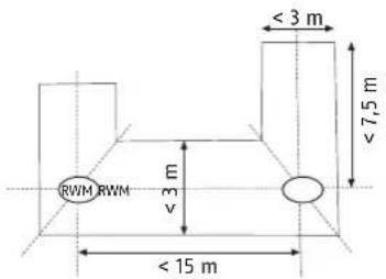
• Maximum distance from the front walls: 7.5 m
• Maximum distance between detectors: 15 m
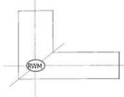
• Installation on the mitre line between intersecting crossings, T-junctions and corner areas
Special case: installation in an L-shaped room
Choosing a location
Special case: ceiling beams


- In the case of ceiling beams measuring > 0.2 m and a total area of < 36 m², detectors should be installed in the centre of the room either on a beam or ceiling panel.
- In the case of ceiling beams measuring > 0.2 m and a total area of > 36 m ^2 , detectors should be installed in the centre of each ceiling panel and not on the beams.
Special case: mezzanines and landings

- In the case of mezzanines and landings with a length and width of >2 m and a total area of >16 m², an additional smoke alarm should be installed in the centre of the surface area.

Choosing a location
Special case: sloped ceilings

- There are no special requirements for ceilings sloped at an angle of < 20^ .
- In the case of ceilings sloped at an angle of >20^ , detectors should be installed 0.5–1 m away from the highest point.
Special case: partially sloped ceilings
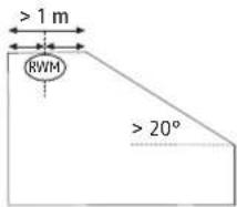
- The instructions for fully sloped ceilings apply for partially sloped ceilings with a horizontal ceiling surface measuring < 1m in width.
- In the case of partially sloped ceilings with a horizontal ceiling surface measuring > 1 m, detectors should be installed in the centre of the horizontal surface.
The smoke alarm should not be installed in the following areas
- outside (use only in internal rooms);
- in areas in which the alarm can be triggered by disturbances (steam, condensation, 'normal' smoke, fumes, dust, dirt or grease);
- next to ventilation or similar air inlets (draughts);
- in areas where temperatures may fall below 0^ C or exceed 45^ C .
Networking
Networking
Up to 12 smoke alarms of type RWM165 can be networked with each other. If a detector detects an alarm, this alarm is indicated optically and acoustically by all networked detectors. Due to the radio connection, a maximum distance of up to 100 metres is possible between the individual detectors in rooms. The range can be negatively influenced by the building construction and structure.
Attention! Do not network wireless smoke detectors of other models with this one. This could lead to malfunctions!
- Switch on the power switch at the bottom of the first smoke detector.
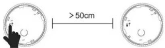
- Press the code button on the bottom of the first smoke detector: the red LED flashes approx. once per second.

Networking
- Switch on the power switch at the bottom of the second smoke detector.

- Press the code button on the bottom of the second smoke detector: the red LED flashes approx. once per second.

- The coding period is approx. 60 seconds. During this time, the two smoke alarms are in coding mode. If both green LEDs of the smoke alarms light up simultaneously, the networking was successful. If they are not successful, the two detectors return to the normal state after 60 seconds.
- Repeat the procedure for all other smoke detectors to be networked. Each additional detector must be networked with a detector that is already networked.
- As soon as you have connected all smoke alarms to each other, press the test / stop button on each smoke alarm and check that the alarm signal is working on all networked smoke alarms. Also check that the red LED only works on the tested smoke detector.
Installation and operation
Installation and operation
In order to mount the alarm on the ceiling, follow the steps in the order listed below:
- Remove smoke alarm from the cover base by turning anti-clockwise.
- Remove the locking pin located in the mounting socket (further use in step 6, is used for unintentional disassembly).
- Mark the holes through the cover base.
- Fit the required dowels into the drill holes and tightly screw in the detector base.


n marking out your drill holes, ensure that no electrical wires cables, pipes or other installation components are located behind the installation point!
- Attach smoke alarm by turning clockwise at the detector base. Small markings are found on the side of the detector base and on the alarm itself which make it easier to fit the alarm onto the base (see illustration on page 40). To be ready for operation, the detector must snap into the socket!
- Insert the locking pin from step 2 into the designated side opening to prevent the alarm from turning (see illustration on page 40).
Installation and operation


Setting up
- If the smoke detector is mounted on the mounting base and the detector is engaged, the detector is supplied with voltage and is activated.
- If the smoke detector is removed from the mounting base, the detector is no longer ready for operation!
Reset to factory setting (radio connection is deactivated)
Press and hold the code button until the red LED flashes (approx. once per second). Approx. 5 seconds later, the red LED will start flashing rapidly (approx. once in 0,5 seconds). Release the button and a short acoustic signal will sound. The smoke alarm has successfully left the network and returned to the factory default settings.
Normal operating mode
The red LED light under the cover will flash approx. every 6 minutes in normal operating mode signalling that the alarm is ready for use.
Installation and operation
Electronic test
Perform regular functional tests on your smoke alarm by holding down the test / stop button (for approx. 5 seconds). The warning tone will sound and the red 'ALARM' LED light will flash. This does not signal that there is smoke in the room but it is confirmation that the smoke alarm is functioning correctly.

natural_image
Diagram of a circular device with ventilation grilles and a labeled component (no text or symbols)
By testing the device electronics, the mute function is automatically activated for 11 minutes, during which time the LED will flash once every 10 seconds. After this 11-minute period, the detector will automatically turn to normal operating mode, in which the LED will again flash once approximately every 6 minutes.

Always test the functioning of the smoke alarm after installation.
ionally, a monthly inspection is recommended.
Display and functions
Audible and visual signals
| Mode Audible Visual | (Red LED) | Visual(Green LED) | |
| Normal operating mode | - | Flashes once approx. every 320 sec. | |
| Alarm mode | Three cycles 0,5 sec. on, 0,5 sec. off, then 1,5 sec. off (repetitive) | Flashes 2x per second | |
| Other networked smoke detectors: Three cycles 0,5 sec. on, 0,5 sec. off, then 1,5 sec. off (repetitive) | Other networked smoke detectors: Off | ||
| Test | Three cycles 0,5 sec. on, 0,5 sec. off, then 1,5 sec. off (repetitive) | Flashes 2x per second | |
| Other networked smoke detectors: Three cycles 0,5 sec. on, 0,5 sec. off, then 1,5 sec. off (repetitive) | Other networked smoke detectors: Off | ||
Display and functions
| Mode Audible Visual | (Red LED) | Visual (Green LED) | |
| Mute Off | Flashes 2x per second | ||
| Smoke chamber error | One audible beep every 40 seconds (separate from the LED) | Flashes once every 40 sec. (separate from the buzzer) | |
| Low battery | Smoke detector with exhausted battery: audible beep once every 40 seconds (synchronous with the LED) | Smoke detector with exhausted battery: flashes once every 40 seconds (synchronous with the buzzer) | |
| Other networked smoke detectors: audible beeps 2x every 4 hours. (synchronous with the LED) | Other networked smoke detectors: flashes 2x every 4 hours. (synchronous with the buzzer) | ||
| Coding running Off | Flashes once every second up to 60 seconds |
Display and functions
| Mode Audible Visual | (Red LED) | Visual(Green LED) | |
| Coding required 1 short beep Off | Lights up for 10 sec. | ||
| Alarm buffer | At any time before the next alarm, press the test button, 3 audible beeps per second. Release of the test button should reset the alarm. | 3x flashes every 40 seconds up to 24 hours. | |
| End of life | 3 audible beeps every 40 seconds | ||
| Factory setting 1 audible beep | 2x flashes per second | ||
Low battery
Whenever the warning signal sounds the alarm must be immediately replaced with a new one! The alarm has a built-in battery that cannot be replaced!

In the moment of the first battery warning, the alarm will still operate all capability for at least another 30 days
Display and functions
Self-test with automatic error message
The smoke alarm will perform a periodic self-test and it is able to recalibrate the sensitivity of the smoke measure chamber automatically in case of contamination. If the alarm's sensitivity trigger fails under the minimum required threshold level (e.g. due to excessive contamination of the smoke measure chamber), the unit will beep once every 40 seconds.

error message does not clear upon cleaning of the alarm, then the alarm should be immediately replaced (see chapter entitled 'Care maintenance')!
Alarm mode
Upon detection of smoke, a loud, pulsating alarm tone will sound and the red LED light will flash simultaneously at short intervals. In this case, proceed as described under the chapter entitled 'Emergency procedure when alarm sounds'.
Alarm mute function
Once the device is in alarm mode, the alarm sound can be deactivated for approx. 11 minutes by pressing the test / stop button.
If the mute function is active, the red LED will flash 2x per second.
If, after this 11-minute mute period, fire smoke is still detected in the smoke measuring chamber, the acoustic alarm will sound again.

natural_image
Diagram of a circular device with ventilation slots and an arrow pointing to a component (no text or symbols)
Only activate the alarm mute function when you are absolutely sure that you can exclude a cause of fire!
$$ - 4 4 - - 4 5 - $$
Care and maintenance
Alarm buffer
This function can be used to identify a smoke detector that has previously triggered an alarm and returned to normal mode.
In this case, the green LED flashes three times every 40 seconds. After triggering, the alarm is displayed for 24 hours. The indicator is then stopped to conserve battery power. If the battery is already low, this indicator is not activated.
The alarm memory function can be stopped prematurely by pressing the test button.
Care and maintenance
What to do in case of false alarm?
Possible causes of false alarm include: Welding and cutting, soldering and other hot work, sawling and grinding, dust created from building work, e.g. cleaning, extreme electromagnetic effects, changes in temperature which lead to condensation in the alarm as well as small insects and pollen.

false alarm is being caused by work close to the device, it should be temporarily covered up or removed. Upon completion of the work, it is imperative, however, that the device be returned to its original operate-state and be checked!
Cleaning
The operation of every installed smoke alarm must be regularly checked and kept safe through maintenance measures in accordance with German DIN 14676 application standards. This includes an inspection at least once every 12 months ± 3 months, including maintenance and checking the performance of the warning signals. The results and measures taken should be documented accordingly.

st covered alarms must be cleaned. Dust deposits in the alarm's air nts can be sucked up or blown out.
st can be removed with a brush if required.
• The surface area can be cleaned with a slightly damp and soapy cloth.
• Take care that no liquids get into the apparatus! Do not clean device in a dishwasher!
- Do not use any sharp, pointed, abrasive or caustic cleaning products, chemicals or hard brushes!
Maintenance
The electronic components of each smoke alarm are subject to ageing. In addition, insect screens and smoke measure chambers will inevitably become contaminated over time.
- Operating life of the device: The smoke alarm must be replaced no later than 10 years + 6 months after the manufacturing date.
Warranty
ABUS products are designed, manufactured and tested in accordance with applicable regulations with great care. The warranty exclusively covers faults that are caused by material or manufacturing defects. If a material or manufacturing defect can be proven, the product will be repaired or replaced at the discretion of the warrantor. In such cases, the warranty ends with the termination of the original warranty period. Any further claims are expressly excluded. ABUS assumes no liability for defects or damage that has been caused by external influences (e.g. transport, external forces), improper use, normal wear and tear or non-compliance with this operating and installation instructions document. If a warranty claim is asserted, the product must be returned with the original receipt with date of purchase and a brief written description of the fault.
Disposal
This product contains valuable raw materials. At the end of its service life, dispose of the product in accordance with the applicable legal requirements. Electrical appliances, rechargeable batteries and batteries must not be disposed of with household waste. Disposal must be carried out in accordance with Directive
2012/19/EU on waste electrical and electronic equipment (WEEE), or Directive 2006/66/EC on batteries and accumulators and waste batteries and accumulators. Batteries must be removed from electrical appliances and disposed of separately before disposal. Dispose of the packaging according to type. Separate the cardboard, foil and plastic elements for recycling. Please contact the local authority responsible for disposal if you have any queries. You can obtain information on collection points for your old appliances, for example, from the local municipal or city administration, the local waste disposal companies, or your specialist dealer.
Declaration of Performance 2019RWM165
This smoke alarm has been tested and certified as a construction product in accordance with EU Regulation 305/2011. It has been manufactured subject to monitoring by regular and independent inspections for continued compliance with legal and normative requirements. The Declaration of Performance can be found at www.lease.comensmoke alarm type (RWM165) in the above right field, then go to downloads. Double-click here to view the Declaration of Performance.
Declaration of Conformity
Hereby, ABUS August Bremicker Söhne KG declares that the radio equipment type RWM165 is in compliance with Directives 2014/53/EU and 2011/65/EU. The full text of the EU declaration of conformity is available at the following internet address: docs.abus.com
The product RWM165 is certified according to VdS guideline 3131 (Q).
Subject to technical alterations. No liability for mistakes and printing errors.
RWM165

Security Tech Germany
natural_image
Line drawing of a circular mechanical component with ventilation slots and a labeled mounting point (no text or symbols)Manuel utilisateur
natural_image
Diagram of a circular device with ventilation grilles and a labeled component (no text or symbols present)
natural_image
Diagram of a circular device with internal components and an arrow pointing to a component (no text or symbols)
natural_image
Line drawing of a circular mechanical component with ventilation slots and a labeled mounting point (no text or symbols beyond the label)natural_image
Technical line drawing of a circular mechanical component with internal grooves and a labeled component (no text or symbols)
natural_image
Top-down diagram of a circular device with ventilation slots and a labeled component (no text or symbols)

Security Tech Germany

natural_image
Line drawing of a circular mechanical component with a flat top and side grooves (no text or symbols)natural_image
Diagram of a circular device with ventilation grilles and a labeled component (no text or symbols present)
natural_image
Diagram of a circular device with ventilation slots and a labeled component (no text or symbols present)
ABUS August Bremicker Söhne KG | D 58292 Wetter | Germany.
Tel.: +49 (0) 23 35 63 40 | w|ww.abus.com info@abus.de
UK-Importer: ABUS (UK) Ltd.
Unit 8 Third Way Corner,
Avonmouth
Bristol BS11 9HL, UK
Tel.: +44 117 204 70 00 | info@abus-uk.com




- Contents
- Notes to accompany user manual
- Intended use
- Limitation of liability
- Packaging
- Scope of delivery
- Safety information
- Battery recommendations
- Functions
- Technical data
- Functions and technical features
- Emergency procedure when alarm sounds
- Special case: ceiling beams
- Special case: mezzanines and landings
- Special case: sloped ceilings
- Special case: partially sloped ceilings
- The smoke alarm should not be installed in the following areas
- Networking
- Installation and operation
- Setting up
- Reset to factory setting (radio connection is deactivated)
- Normal operating mode
- Electronic test
- Low battery
- Self-test with automatic error message
- Alarm mode
- Alarm mute function
- Alarm buffer
- Care and maintenance
- Cleaning
- Maintenance
- Warranty
- Disposal
- Declaration of Performance 2019RWM165
- Declaration of Conformity
- RWM165
Brand : ABUS
Model : RWM165
Category : Smoke detector