
VFG5008WIT - Cooker INVENTUM - Free user manual and instructions
Find the device manual for free VFG5008WIT INVENTUM in PDF.

| Product Type | Gas Cooker |
| Brand | Inventum |
| Model | VFG5008WIT |
| Dimensions (H x W x D) | 850 x 600 x 600 mm |
| Weight | Approximately 55 kg |
| Gas Supply | Natural gas (G20/G25.3) or LPG (G30) after conversion |
| Power Supply | 230 V ~ 50 Hz, single-phase |
| Burners | 1 rapid burner (2.8 kW), 2 normal burners (1.8 kW each), 1 simmer burner (1.0 kW) |
| Oven Type | Multifunction: fan-assisted, grill, natural convection, defrosting, lighting |
| Maximum Oven Temperature | 250 °C |
| Number of Oven Shelves | 3 |
| Safety | Safety thermocouple on each burner, anti-tip protection |
| Cleaning | Removable oven door, removable inner glass, steam cleaning possible |
| Included Accessories | Grid, drip tray, spare injectors for gas conversion |
| Warranty | 2 years full, extension to 5 years upon registration |
| Repairability | Replaceable oven bulb (25W, E14), interchangeable injectors |
Frequently Asked Questions - VFG5008WIT INVENTUM
User questions about VFG5008WIT INVENTUM
0 question about this device. Answer the ones you know or ask your own.
Ask a new question about this device
Download the instructions for your Cooker in PDF format for free! Find your manual VFG5008WIT - INVENTUM and take your electronic device back in hand. On this page are published all the documents necessary for the use of your device. VFG5008WIT by INVENTUM.
USER MANUAL VFG5008WIT INVENTUM
natural_image
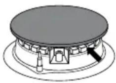
White kitchen stove with four gas stove covers and open top (no visible text or symbols)- safety instructions page 21
- appliance description page 25
- before first use page 26
- installation page 26
- how to use the burners page 30
- operating the convection oven page 31
- baking tips and baking tables page 32
- cleaning and maintenance page 34
- problems and solutions page 36
General terms and conditions of service and warranty page 74
Deutsch
natural_image
Technical line drawings of two rectangular metal components with labeled parts (17 and 18), no text or symbols present.natural_image
Technical line drawing of a mechanical clamp or bracket (no text or symbols)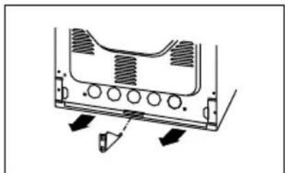
natural_image
Technical diagram of a mechanical component with arrows indicating motion or force direction (no text or symbols)HET FORNUIS AANSLUITEN OP DE GASINSTALLATIE
Opgelet!
natural_image
Pure technical diagram of a circular component with a central arrow pointing to it, no text or symbols present.natural_image
Pure mechanical component diagram without any text, numbers, or symbols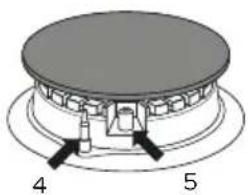
natural_image
Two circular diagrams with arrows indicating rotational or directional movement, no text or symbols presentSLECHT GOED
Opgelet!
natural_image
Diagram showing three stages of a mechanical component with an arrow indicating direction (no text or symbols present)OVENDEUR DEMONTEREN EN MONTEREN
natural_image
Technical line drawing of a mechanical assembly with an inset showing a detail of a component (no text or symbols present)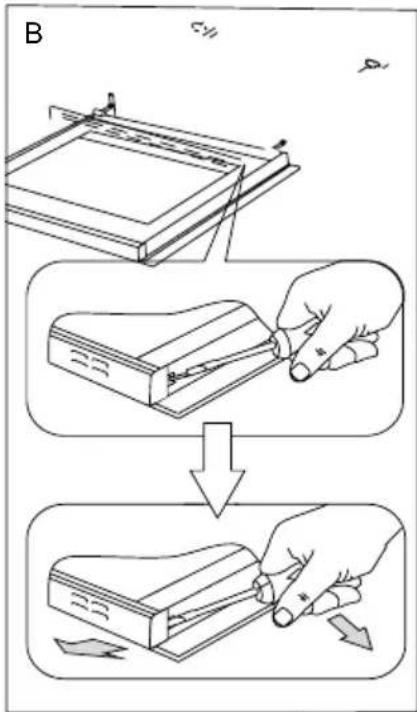
natural_image
Diagram of a mechanical assembly with a rectangular frame and a separate plate, showing no text or symbols.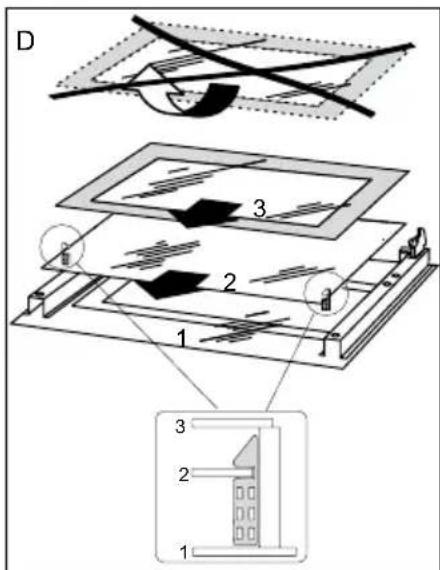
REGELMATIGE CONTROLE
1 safety instructions
- Please read these instructions before operating the appliance and retain for future use.
- The appliance is intended solely for domestic use within the home. Do not use corrosive chemicals or vapors in this appliance. This cooker is especially designed to prepare food. It is not designed for industrial or laboratory use.
- WARNING: this appliance and the accessible parts will become hot during use. Do not touch hot parts. Keep children younger than 8 away from the appliance unless they are under continuous supervision.
- This appliance can be used by children aged 8 years and over, as well as by people with reduced physical, sensory or mental capabilities or lack or experience and knowledge, provided they are supervised and instructed in the safe use of the appliance and understand the hazards involved.
• Children must not play with the appliance. - Cleaning and maintenance shall not be made by children.
- Do not keep objects that children might find interesting in cupboards above or behind the appliance.
- The cooking zones heat up during use and stay hot for a while afterwards. Keep young children away from the stove during and immediately after cooking.
- Warning: Liquids and other foods must not be heated in sealed containers since they are liable to explode.
- In preparing meals containing alcohol, high temperatures may cause the alcohol to evaporate. The vapour can catch fire if it comes into contact with hot parts. Be careful opening the oven door.
- The outside of the cooker may become hot if it is used for a long period of time at high temperatures. If the oven is used at the maximum temperature for a long time, the glass panel in the oven door may become hot. Please be careful if children are around.
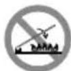
- WARNING: danger of fire: never leave anything on the stove.
WARNING: cooking with fat or oil on a stove without supervision can be dangerous and can lead to fire. NEVER try to extinguish a fire with water. Instead, switch the appliance off and then cover the flames with for example a lid or a fire blanket.
- The cooker should be cleaned regularly and any food deposits should be removed.
- Do not use any abrasive cleaners or metal scrapers to clean the glass door. This will scratch the surface which may cause the glass to break.
- Do not use the appliance as a worktop. The appliance may accidentally be switched on or still be hot or catch fire.
- Never cover the appliance with a cloth or something similar. If the appliance is still hot or is switched on, there is a risk of fire.
- The appliance may not be cleaned with a high-pressure cleaner or a steam cleaner.
- When you see smoke, switch off and unplug the oven. Keep the oven door closed in order to stifle any flames.
- Ensure that the appliance is switched off before replacing the lamp to avoid the possibility of electric shock.
- Do not place accessories on the open oven door.
- Never cover the bottom of the oven with aluminium foil. The foil blocks the heat flow, which may result in inferior cooking results. This can also damage the enamel of the bottom of the oven.
- The cooker has a fan that cools the oven casing. The fan may run for some time after the oven is switched off.
- Ensure that there is adequate ventilation during use.
- Keep all natural ventilation openings open.
- When using the cooker for long periods, extra ventilation is necessary. For example, open a window or install an electric fan.
- Never flambé under a cooker hood. The high flames can cause a fire, even if the cooker hood is switched off.
- The burner components are hot during and immediately after use.
- Do not touch, and avoid contact with non-heat resistant materials.
- Never immerse the hot burner caps and pan supports in cold water. The rapid cooling can damage the enamel.
- The distance between the pan and a knob or non-heat resistant wall should always be greater than two centimetres. In case of smaller distances the high temperature may cause the knobs or
wall to discolour and/or deform.
• Always use the pan supports and suitable cookware.
• Always place the pan on the pan support. Placing the pan directly on the burner cap can result in dangerous situations.
- Aluminium trays or foil are not suitable as cooking utensils. They can burn into the burner caps and pan supports.
- The cooker can only function effectively if the burner components have been assembled using the guide ridges. Ensure that the pan supports lie properly against each other and flat on the drip tray. Only then the pans can be positioned stably.
- Keep oven gloves or oven cloths away from the flame.
• Always raise the glass cover when using the stove.
- The glass cover can break through heating. Ensure that all burners are switched off and have cooled down before closing the cover.
- If there is water on the cover, dry it before opening. If you fail to do so, moisture may enter the cooker.
- Do not use the decorative cover as a cooking surface.
- The appliance should only be connected by a registered installer.
- Faulty parts may only be replaced by original parts. The manufacturer can only guarantee that original parts meet safety requirements.
- If the connecting cable is damaged, it may only be replaced by the manufacturer, the manufacturer's service organisation or equivalently qualified persons, in order to avoid dangerous situations.
- The appliance should not be connected to the network via a multi-plug socket or extension lead, as the safe use of the appliance can then not be guaranteed.
- The appliance must always be earthed.
- The walls and the worktop surrounding the appliance must be heat resistant up to at least 85°C. Even though the appliance itself does not get hot, the heat of a hot pan could discolour or deform the wall.
- Failure to maintain the cooker clean could lead to deterioration of the surface that could adversely affect the life of the appliance and possible result in a hazardous situation.
- Move the appliance with at least two people and wear protective clothing, such as sturdy gloves.
- Do not lift the appliance by the handle of the oven door.
- The appliance is not intended to be operated by means of an external timer or separate remote-control system.

- Before plugging into a socket, check that the voltage in your home corresponds with the voltage printed on the appliance.
- The safety during use can only be guaranteed when the cooker is installed correctly and according to the regulations. The installer is responsible for any damage caused by a faulty installation.
- The gas connection must comply with the national and local safety regulations. The gas connection must be made by qualified installer.
- The electrical connection must be made by a qualified electricien. This person is aware of the national and local regulations the installation must comply with.
- The appliance falls under protection class I and can only be used in combination with a grounding conductor connection. The manufacturer accepts no responsibility for any malfunction or damage caused by incorrect electrical installations.
- The appliance must be connected to a fixed installation and the means of disconnecting it from the fixed installation must be installed according to the installation instructions.
- The connection cable must hang freely. Do not tie the power cable or pass it along sharp edges. It must be positioned so that it does not touch any of the hot parts of the cooker.
- The connection point, the wall socket and/or plug must always be accessible.
- Never immerse the power cord and plug into water or any other liquid to protect yourself against electrical hazards.
- If the appliance is used for other purposes than intended, or is it not handled in accordance with the instruction manual, the full responsibility for any consequences will rest with the user. Any damages to the product or other things are not covered by the warranty.
- Should you decide not to use the appliance anymore, make it inoperative by cutting the power cord after removing the plug from the socket. We also recommend making all potentially dangerous parts of the appliance harmless, particularly for children who might be tempted to play with it.
• Legislation requires that all electrical and electronic equipment must be collected for reuse and recycling. Electrical and electronic equipment marked with the symbol indicating separate collection of such equipment must be returned to a municipal waste collection point.

equipment must be collected for reuse and recycling. Electrical and electronic equipment marked with the symbol indicating separate collection of such equipment must be returned to a municipal waste collection point.
2 appliance description
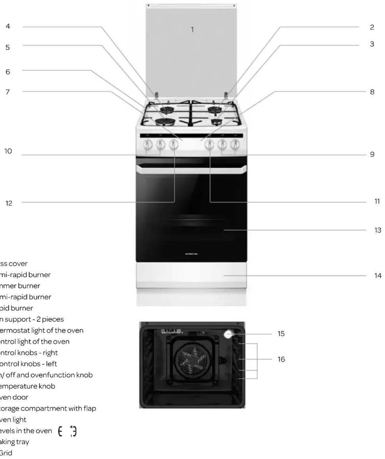
natural_image
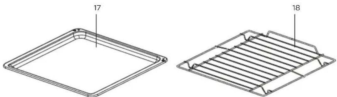
Technical line drawings of two metal frame components, one with a rounded square top and labeled '17', the other with a grid-like structure and labeled '18' (no text or symbols beyond labels)25 • English
3 before first use
Before you use the appliance for the first time, please do as follows: Carefully unpack the appliance and remove all the packaging material. Keep the material (plastic bags and cardboard) out of reach of children. Check the appliance after unpacking for any damage, possible from transportation. Check that the voltage in your home corresponds with the voltage printed on the bottom of the appliance and plug it in a socket. Follow the installation instructions in chapter INSTALLATION for installing the cooker.
Clean the cooker and all the accessories with warm water and a mild cleaning detergent. Rinse well and dry thoroughly. Operate the oven for about 30 minutes at the maximum temperature to burn off all traces of grease which might otherwise create unpleasant smells when preparing food.
4 installation
The following instructions are addressed to the qualified specialist installing the cooker. These instructions aim at ensuring that installation and maintenance activities are performed as professionally as possible.
- Ensure that the local distribution conditions (nature of the gas and gas pressure) and the adjustment of the appliance are compatible before installing the cooker.
• The adjustment conditions are stated on the rating label. - This appliance is not connected to a combustion products evacuation device. It shall be installed and connected in accordance with current installation regulations. Particular attention shall be given to the relevant requirements regarding ventilation.
- Move the appliance with at least two people and wear protective clothing, such as sturdy gloves.
- Do not lift the appliance by the handle of the oven door.
INSTALLING THE COOKER
- The kitchen should be dry and well ventilated and have effective ventilation according to the existing technical provisions.
- The room should be equipped with a ventilation system that pipes away exhaust fumes created during combustion. This system should consist of a ventilation grid or hood. Hoods should be installed according to the manufacturer's instructions. The cooker should be placed so as to ensure free access to all control elements.
- The room should also enable the necessary air supply for proper gas combustion. Air supply should be not less than 2m^3/h per 1 kW of burner heat. The air can be delivered from outside by a duct with a section of at least 100cm^2 , or indirectly from adjoining rooms which are fitted with ventilation ducts leading outside.
- If the appliance is used intensively and for a long time, it may be necessary to open a window in order to improve ventilation.
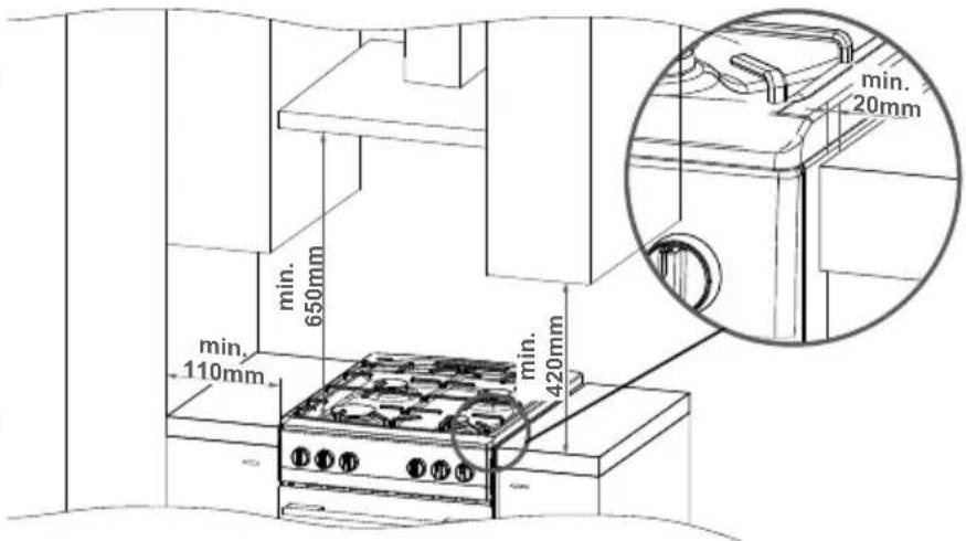
- In terms of protection against the overheating of surrounding surfaces, the gas cooker is an X – class appliance and can be built into furniture only up to the level of the cooking hob, that is around 850 mm above the floor. Raising furniture construction over this level is inadvisable. Coating or veneer used on fitted furniture must be applied with a heat resistant adhesive (100°C). This prevents surface deformation or detachment of the coating. If you are unsure of your furniture's heat resistance, you should leave approximately 2 cm of free space around the cooker. The wall behind the cooker should be resistant to high temperatures. During operation, its back side can warm up to around 50°C above the ambient temperature.
• The cooker should stand on a hard, even floor (do not put it on a base). - Before you start using the cooker it should be leveled, which is particularly important for fat distribution in a frying pan. To this purpose, the adjustable feet are accessible after removal of the drawer. The adjustment range is ± 5 mm.
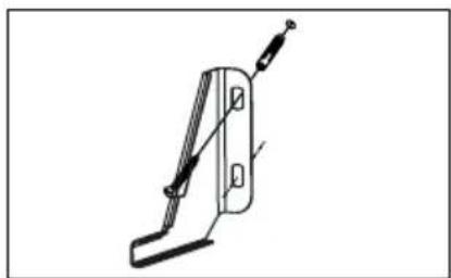
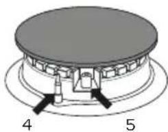
MOUNTING THE OVERTURNING PREVENTION BRACKET
The bracket is mounted to prevent overturning of the cooker. When the overturning prevention bracket is installed, a child who climbs on the oven door will not overturn the appliance.
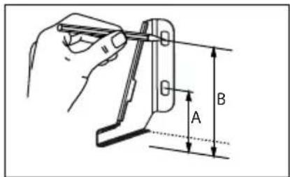
Cooker, height 850 mm
A = 60 mm
B = 103 mm
Cooker, height 900 mm
A=104mm
B=147mm
natural_image
Simple line drawing of a mechanical clamp or bracket (no text or symbols)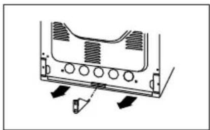
natural_image
Technical diagram of a mechanical component with arrows indicating motion or force direction (no text or symbols)GAS CONNECTION
Caution!
The cooker should be connected to a gas supply of the particular type of gas that the appliance is manufactured to function with. Information about the type of gas that the cooker has been adapted to by the factory is shown on the rating label. The cooker should be connected exclusively by an appropriately authorised fitter and only that person has the right to adapt the cooker to a different type of gas..
Fitting guidelines
A fitter should:
• have a gas fitter's authorisation;
- be acquainted with the information included on the rating label of the cooker about the type of gas to which the cooker is adapted; the information should be compared with the gas supply conditions at the place of installation;
- check:
- airing efficiency, that is efficiency of air exchange in the rooms;
- tightness of gas fitting connections;
- effectiveness of alle functional elements of the cooker;
- if the electricity supply is adapted to function with a safety ground lead (zero).
- check the settings of the control knobs for the burnersde to ensure good functioning of the ingition and the thermocouple.
Caution!
The cooker may only be connected to a liquid gas cylinder of the existing gas supply by an authorised fitter, observing all safety rules.
Connection with a flexible steel hose
If the cooker is connected according to the class 2 specifications, sub-class I, only flexible metal hose can be used which meet the valid national regulations. Gas feeding connector must be G 12 " threaded coupling. Use only pipes and fittings that meet the requirements of the valid standards. Maximum admissible length of the flexible hose is 2000 mm. Make sure the connection is not touching any mobile elements which could damage the hose.
Connection with a stable pipework
The cooker comes with a G 12 " threaded coupling. The connection to gas supply must be done in a manner that excludes stresses in any point of the pipework or parts of the appliance. Make sure you do not exceed the torque when making the connection (maximum torque is 20 Nm). Otherwise, the connection may be faulty or leaks may occur.
The gas hose should not touch metal elements of the cooker back shield.

Important! Each time you replace a reducer, carry out technical inspection of the cooker that covers gas valves and proper operation of the flame failure cut-off device.
Caution! On completion of the cooker installation, the tightness of all connections should be checked, e.g. applying water with soap. Do not use fire to check tightness.
ELECTRICAL CONNECTION
- The cooker is manufactured to work with a one-phase alternating current (230V 1N\~50Hz) and is equipped with a 3 × 1.5 ~mm^2 connection lead of 1.5 ~m length with a plug including a protection contact.
- A connection socket for electricity supply should be equipped with a protection pin and may not be located above the cooker. After the cooker is positioned, it is necessary to make the connection socket accessible to the user.
-
Before connecting the cooker to the socket, check if:
-
the fuse and electricity supply are able to withstand the cooker load,
- the electricity supply is equipped with an efficacious ground system which meets the requirements of current standards and provisions.
- the plug is within easy reach.
ADAPTING THE COOKER TO ANOTHER TYPE OF GAS
This operation may only be carried out by an appropriately authorised fitter.
If the gas the cooker is to be supplied with differs from the gas provided for the cooker by the manufacturer, that is G25.3 / 25 mbar, burner nozzles must be exchanged and the flame needs to be adjusted.
In order to adapt the cooker to burn a different type of gas, you should:
• exchange the nozzles (see the gas tables below);
- adjust the "economical" flame.
Caution! The cookers provided by the manufacturer have burners which are factory-adapted to use the gas specified on their rating labels.
Gas table
| G25.3/25 mbar* G20/20 | mbar G30/30 mbar | SOMIPRESS burners | |||||
| Injector diameter | Injector mark | Injector diameter | Injector mark | Injector diameter | Injector mark | ||
| 1 0.70 mm 71 0.72 mm | 72 0.52 mm 52 1 | Simmer burner | 1.0 kW | ||||
| 2 0.98 mm 98 0.98 mm | 98 0.67 mm 67 | 2 Semi-rapid burners 1.8 kW | |||||
| 3 1.17 mm 116 1.17 mm | 117 0.83 mm 83 1 | Rapid burner | 2.8 kW | ||||
| Burner flame Re-arming from liquid gas to natural gas | Re-arming from natural gas to liquid gas | |
| Full | 1. Exchange a burner nozzle for the appropriate type according to the gas table. | 1. Exchange a burner nozzle for the appropriate type according to the gas table. |
| Economical | 2. Unscrew an adjusting bolt slightly and adjust the flame size. | 2. Screw in an adjusting bolt slightly and check the flame size. |
In order to perform adjusting operations, take off the knobs.
Surface burners applied do not require adjustment of primary air. A correct flame has distinct internal cones of blue and green colour.
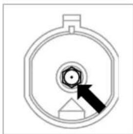
A short, humming flame or long, yellow and smoking one, without clearly outlined cones, shows improper quality of gas in the household piping or a damaged or soiled burner. In order to check a flame, heat a burner for around 10 minutes with a full flame, and next turn the valve knob to the economical flame position. The flame should not go out or jump onto the nozzles.
natural_image
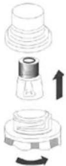
Pure technical diagram of a circular component with a central bolt and arrow, no text or symbols presentExchange of a burner nozzle
Unscrew the nozzle with a special socket spanner No 7 and replace with a new one according to a type of gas (see gas tablel).
Caution! Adapting the appliance to a different type of gas than is indicated by the manufacturer of the cooker on the rating label, or purchasing a cooker for a different type of gas than supplied to the house, is exclusively the responsibility of the user and the fitter.
natural_image
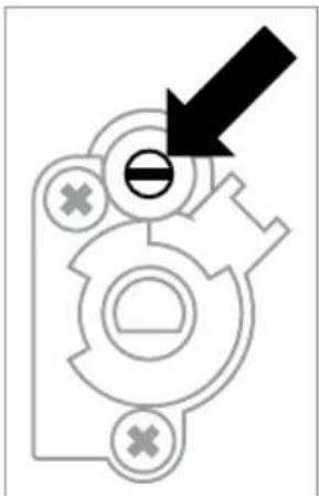
Pure mechanical diagram with no text, numbers, or symbolsIn cookers with a safety device, a knob with a surface burner safety valve is used, fig. Knobs should be adjusted with the burner switched on and set to the economical flame position, using an adjustment screwdriver of the size 2.5 mm.
Caution! After adjustment is completed, place a label indicating the type of gas to which the cooker is now adapted.
5 how to use the burners
CHOICE OF COOKWARE
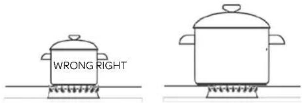
• Always ensure that the flames remain under the pan. When the flames burn around the pan, a lot of energy is lost and the handles from the pan may also become too hot.
- Use cookware that fit the burners in diameter. This reduces the cooking time.
• Use flat bottomed cookware.
• Always use the right amount of liquid for boiling food and use a lid to reduce the cooking time.
• The recommended pan diameter is around 2.5 to 3 times larger than the burner diameter, that is, for:
• for a simmer burner - a pan with a diameter of 90 to 150 mm
• for a semi-rapid burner - a pan with a diameter of 160 to 220 mm
- for a wok burner - a pan with a diameter of 200 to 240 mm and the pan height should not be greater than its diameter.
CONTROL KNOBS FOR THE BURNERS
Before operating the hob please make sure that the burner caps are well positioned.
- burner switched off ●
- large flame
- economical flame
- thermocouple
- ignition
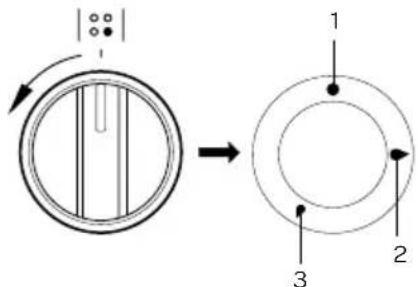

Attention: always open the cover when using the cooker.
Each control knob has an automatic ignition.
- Press the control knob and turn it anticlockwise to the setting "large flame"
- Hold the control knob down fully for at least 3 seconds between the highest and the lowest flame. The integrated ignition ignites the burner and the flame comes on.
- Hold down the control knob for 10 more seconds after the flame is on to activate the thermocouple. Otherwise the flame extinguishes immediately.
- When the burner is not ignited after 15 seconds, wait one minute before trying to ignite it again.
- When the burner accidentally goes out, the thermocouple safety pilot in each burner will close the gas supply (by boiling over, by drafts, no gas supply, etc.). No flame = no gas!
A correctly adjusted burner has a light blue flame with a clearly visible internal cone. Selection of the flame size depends on the position of the control knob of the burner which has been set:
large flame
small flame ("economical flame")
● burner switched off (gas supply is cut off)
Depending on requirements, the flame size can be set in a continuous manner.
natural_image
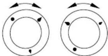
Two identical circular diagrams with arrows indicating rotational or directional movement, no text or symbols present.WRONG RIGHT
Caution!
Do not adjust the flame between the position off ● and the large flame position 🔒.
6
operating the convection oven
The convection oven can be heated up using the bottom and top heating elements and the fan heater.
SWITCHING ON
To switch the oven on, turn the oven function knob to the desired setting and the temperature knob to the right temperature. As soon as the oven has reached the set temperature, the thermostat light goes out.
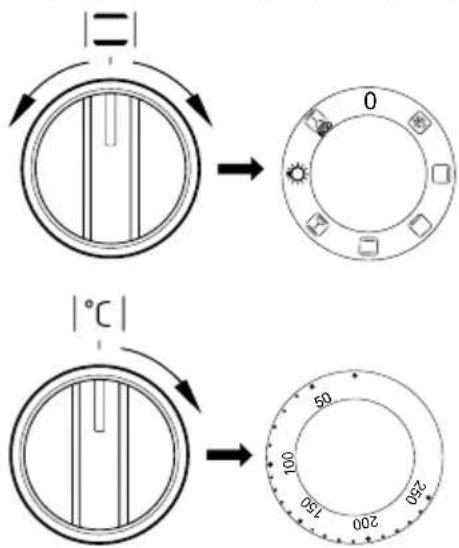
SWITCHING OFF
To switch the oven off, turn both knobs back the off setting [● / 0].
Caution! When selecting any heating function, the oven will only be switched on after the temperature has been set by the temperature knob.
The oven has the following functions:
| Ovenfunction Description | ||
| 0 Off The | oven is turned off. | |
 | Defrosting Only the fan is on and all heating elements are off. | |
 | Bovenste verwarmings-element | With this function only the top heating element is on. Use for final baking from above. |
 | Bottom heating element | With this function only the bottom heating element is on. for baking of cakes from the bottom until done (e.g. moist cakes with fruit stuffing). |
 | Top and bottom heating element | With this function the oven is heated for conventional baking. This setting is ideal for baking cakes, meat, fish, bread and pizza on one level (it is necessary to preheat the oven and use dark coloured baking tins). |
 | Convection: top and bottom heating element with fan | This function is most suitable for baking cakes.When this function is selected but the temperature knob is set to 0 only the fan will be on. This could be helpful for cooling down a dish or the oven chamber. |
 | Oven lighting | The oven light can be switched on independent from the oven. When selecting this function the inside of the oven is lit. |
 | ECO fan assisted heating | This is an optimised heating function designed to save energy when preparing food. The oven lighting is off during use of this function. |
Switching on the oven is indicated by two signal lights, a thermostat light and a control light.
The control light on the right next to the timer turned on, means the oven is working.
When the thermostat light, on the left of the timer, goes out, the oven has reached the set temperature. If a recipe recommends placing the dish in a pre-heated oven, this should not be done before the thermostat light goes out for the first time.
When baking, the thermostat light will temporarily come on and off (to maintain the temperature inside the oven).
The control light can also be on when the oven function knob is set to the function "Oven lighting".
31 • English
7 baking tips and baking tables
BAKING
- Use the supplied baking tray or grid for preparing cakes and pastries.
- It is also possible to bake in cake tins and trays bought elsewhere which should be put on the grid; for baking it is better to use black trays which conduct heat better and shorten the baking time;
- Shapes and trays with bright or shiny surfaces are not recommended when using the conventional heating method (top and bottom heaters), use of such tins can result in undercooking the base of cakes;
- Before the cake is taken out of the oven, check if it is ready using a wooden stick (if the cake is ready the stick should come out dry and clean after being inserted into the cake).
• After switching off the oven it is advisable to leave the cake inside for about 5 minutes. - The baking parameters given in the baking table are approximate and can be corrected based on your own experience and cooking preferences.
- If information given in recipe books is significantly different from the values included in this instruction manual, please apply the instructions from the manual.
ROASTING MEAT
- Cook meat weighing over 1 kg in the oven, but smaller pieces should be cooked on the gas burners.
- Use heatproof ovenware for roasting, with handles that are also resistant to high temperatures.
- When roasting on the drying rack or the grate we recommend that you place a baking tray with a small amount of water on the lowest level of the oven.
- It is advisable to turn the meat over at least once during the roasting time and during roasting you should also baste the meat with its juices or with hot salty water – do not pour cold water over the meat.
ECO FAN HEATER
- This is an optimised heating function designed to save energy when preparing food. The oven lighting is off during use of this function.
- You cannot reduce the cooking time by setting a higher temperature; preheating the oven is not recommended.
- Do not change the temperature setting and do not open the oven door during cooking.
Recommended settings for ECO Fan Heater
| Type of dish Oven function | Temperature - °C | Level (°) | Time in minutes | |
 |  | 180 - 200 2 - 3 50 - 70 | ||
 |  | 180 - 200 250 - 70 | ||
 |  | 190 - 210 2 - 3 45 - 60 | ||
 |  | 200 - 220 290 - 120 | ||
 |  | 200 - 220 290 - 160 | ||
 |  | 180 - 200 280 - 100 | ||
BAKING TABLE when using the other functions
| Type of dish Oven functions | Temperature - °C | Level (°) | Time in minutes | |
 |  | 160 - 200 2 - 3 30 - 50 | ||
 |  | 150 3 25 - 35 | ||
 |  | 160 - 170^1) | 3 25 - 40 | 2) |
 |  | 155 - 170^1) | 3 25 - 40 | 2) |
 |  | 220 - 240^1) | 2 15 - 25 | |
 |  | 210 - 220 2 45 - 60 | ||
 |  | 225 - 250 2 120 - 150 | ||
 |  | 160 - 230 2 90 - 120 | ||
 |  | 160 - 180 2 45 - 60 | ||
 |  | 190 - 210 2 40 - 50 | ||
The times are apply to dish that is placed into a cold oven. For the preheated oven, the times should be reduced by about 5-10 minutes.
^1) Preheat
2) Baking smaller items
Caution! The figures given in the baking table are approximate and can be adapted based on your own experience and cooking preferences.
8
cleaning and maintenance
By ensuring proper cleaning and maintenance of your cooker you can have a significant influence on the continuing fault-free operation of your appliance. Do not clean the cooker with a steam cleaner or hydroblaster.
Before you start cleaning, the cooker must be switched off. Make sure all control knobs are set to the off position [ ● / 0 ].
Do not start cleaning until the cooker has completely cooled.
CLEANING THE GLASS COVER
Clean the glass cover with a glass-cleaning product. For easy cleaning of the cover and the cooking part of the stove, the cover can be removed.
Open the cover and hold it on both sides. Lift the cover straight upwards.
After cleaning replace the cover in reverse order.
CLEANING THE COOKING PART
Clean the cooker after each use to maintain it in good condition. Food residue can create stubborn stains if not removed directly after use. Use a mild cleaning detergent to clean the hob. Burner parts and the pan supports should not be cleaned in the dishwasher. The dishwasher detergent can corrode the materials.
The pan supports, burners and burner caps are removable for easy cleaning of the cooking part.
- First clean the control knobs, burners, burner caps and pan supports.
- Check whether the thermocouple and ignition are clean. If necessary use a toothpick or needle.
- Clean the drip tray.
- Clean everything again with just a damp cloth and dry it thoroughly.
- Refit the burners. Make sure the openings are aligned for the thermocouple and the ignition.
- Refit the burner caps.
- Refit the pan supports. Place them carefully on the drip tray without sliding.
- Close the glass cover.
natural_image
Diagram of a circular mechanical component with a central hub and mounting base (no text or symbols)PERSISTENT STAINS
Persistent stains on the pan supports and burner caps can best be removed with a fluid detergent or a plastic scouring sponge. Never use aggressive cleaning products or sharp objects to clean the hob.
Persistent stains on stainless steel are best removed with a special stainless steel cleaning product. Always wipe in the direction of the grain to prevent damage to the protective layer.
The surface of the stainless steel drip tray can discolour slightly over time.
CLEANING THE OVEN
The oven should be cleaned after every use. When cleaning the oven the lighting should be switched on to enable you to see the surfaces better. The oven chamber should only be washed with warm water and a small amount of washing-up liquid.
The oven can also be cleand with steam:
- Place a bowl with 250 ml (1 glass) of water on a baking tray on the first level from the bottom in the oven.
- Close the oven door.
- Set the temperature knob to 50^ and the oven function knob on the setting .
- Heat the oven chamber for approximately 30 minutes.
- Open the oven door, wipe the chamber inside with a cloth or sponge and wash the oven chamber using warm water with washing-up liquid.
• After cleaning the oven chamber wipe it dry.
- Never use aggressive cleaning products or sharp objects to clean the oven door.
ACCESSORIES
Clean the accessories, such as the baking tray and the grid with warm water and a mild detergent. Dry thoroughly before reusing.
REPLACING THE OVEN LIGHT BULB
In order to avoid the possibility of an electric shock ensure that the appliance is switched off and unplugged before replacing the bulb.
- Unscrew and wash the lamp cover and then wipe it.
- Replace the light bulb with a new equal bulb (25 W, 230V, E14 connection and must be resistant to high temperatures - upto 300^ ).
- Refit the lamp cover.
- Plug the appliance in.
natural_image
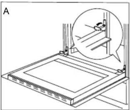
Diagram of a mechanical component with an upward arrow indicating motion or assembly (no text or symbols present)REMOVING AND REPLACING THE OVEN DOOR
The oven door can be removed in order to obtain easier access to the oven chamber for cleaning.
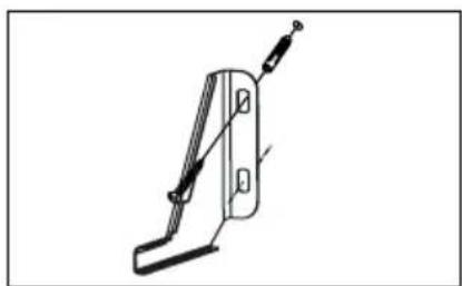
- Open the oven door and tilt the safety catch part of the hinge upwards (fig. A). Close the door a little and lift it up and pull it out towards you in order to remove the door.
• To replace the door, reverse the process. When fitting, ensure that the notch of the hinge is correctly placed on the protrusion of the hinge holder. After the door is fitted to the oven, the safety catch should be carefully lowered down again. If the safety catch is not set it may cause damage to the hinge when closing the door.
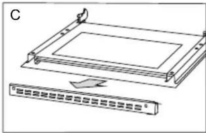
REMOVING AND REPLACING THE INNER GLASS PANEL
To clean the oven door properly, the inner glass panel can be removed.
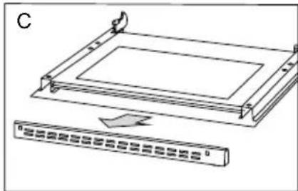
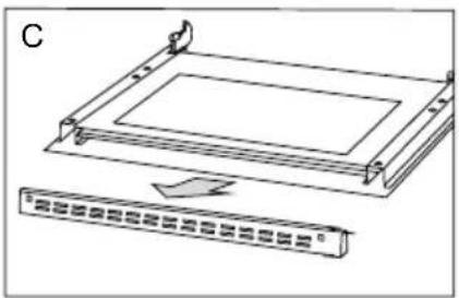
• Using a flat screwdriver unhook the upper door slat, prying it gently on the sides (fig. B).
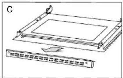
• Pull the upper door slat loose (fig.B, C).
- Carefully pull the inner glass panel from its seat (in the lower section of the door) fig. D.
- Clean the panel with warm water with some washing-up liquid added.
- Carry out the same in the reverse order to reassemble the inner glass panel. Its smooth surface must be pointed upwards.
Important! Do not force the upper strip in on both sides of the door at the same time. In order to correctly fit the top door strip, first put the left end of the strip on the door and then press the right end in until you hear a "click". Then press the left end in until you hear a "click".
natural_image
Technical line drawing of a mechanical assembly with an inset showing a close-up of a component (no text or symbols present)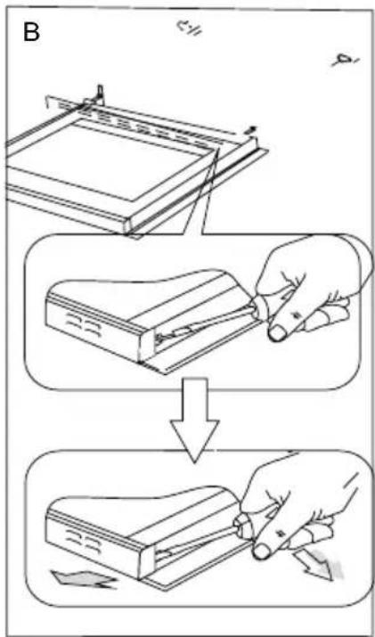
natural_image
Diagram of a rectangular device with a curved arrow pointing to its base, labeled 'C' (no text or symbols on the device itself)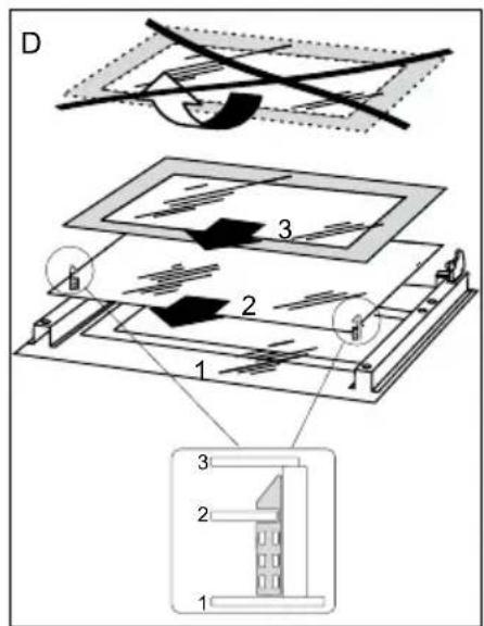
REGULAR INSPECTIONS
Besides keeping the cooker clean, you should also:
- carry out periodic inspections of the control elements and cooking units of the cooker. After the guarantee has expired you should have a technical inspection of the cooker carried out at a service centre at least once every two years;
- fix any operational faults
- carry out periodical maintenance of the cooking units of the cooker.
Caution!
All repairs and regulatory activities should be carried out by the appropriate service center or by an appropriately authorised fitter.
9 problems and solutions
In the event of a problem, you should:
- switch off all working units of the cooker;
- disconnect the mains plug;
- call the service centre;
- some minor faults can be fixed by referring to the instructions given in the table below. Before calling the customer support centre check the following points that are presented in the table.
| Problem Reason Action | ||
| A burner does not light Flame openings | ings are soiled Close the gas with cutting | off valve, close burner knobs, air the room, take out and clean the burner, blow on the flame openings. |
| A gas ignitor does not light Break in | the power supply Check the household | fuse box; if there is a blown fuse, replace it with a new one. |
| Break in the gas supply Open the gas | supply valve. | |
| Soiled (greasy) gas ignitor Clean the gas | ignitor. | |
| Control knob of the burner not pressed in long enough | Hold the control knob pressed in until a full flame appears around the burner crown. | |
| The flame goes out when lighting a burner | Control knob of the burner released too quickly | Hold the control knob down longer at the "large flame" position. |
| The electrical functions do not work | Break in the power supply Check the household fuse box, if there is a blown fuse, replace it with a new one. | |
| The oven lighting does not work The bulb is loose or damaged Tighten up or replace the blown bulb (see the chapter Cleaning and Maintenance). | ||
The appliance was configured for the appliance category K (I2K) and is suitable for the use of G and G+ distribution gases according to the specifications as included in the NTA 8837:2012 Annex D with a Wobbe index of 43.46 – 45.3 MJ/m3 (dry, 0 °C, upper value) or 41.23 – 42.98 (dry, 15 °C, upper value).
This appliance can moreover be converted and/or be calibrated for the appliance category E (I2E).
This therefore implies that the appliance: "is suitable for G+ gas and H gas or is demonstrably suitable for G+ gas and can demonstrably be made suitable for H gas" within the meaning of the "Dutch Decree of 10 May 2016 regarding amendment of the Dutch Gas Appliances Decree...."
natural_image
Technical line drawings of two metal frame components, one with a rounded square top and labeled '17', the other with a grid-like structure and labeled '18' (no text or symbols beyond labels)Herd, Höhe 850 mm
A = 60 mm
B = 103 mm
Herd, Höhe 900 mm
A=104mm
B=147 mm
natural_image
Simple line drawing of a mechanical clamp or bracket (no text or symbols)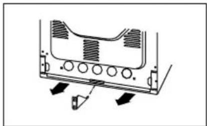
natural_image
Technical diagram of a mechanical component with arrows indicating motion or assembly (no text or symbols)natural_image
Pure technical diagram of a circular component with a central arrow pointing to it, no text or symbols present.natural_image
Pure mechanical component diagram without any text, numbers, or symbols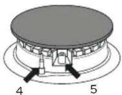
natural_image
Diagram of a mechanical component with labeled parts 4 and 5, showing no readable text or symbols.
natural_image
Two circular diagrams with arrows indicating rotational or directional movement, no text or symbols present.FALSCH RICHTIG
Achtung!
AUSSCHALTEN
natural_image
Diagram showing three stages of a mechanical component with arrows indicating motion (no text or symbols)natural_image
Technical line drawing of a mechanical assembly with an inset showing a close-up of a component (no text or symbols present)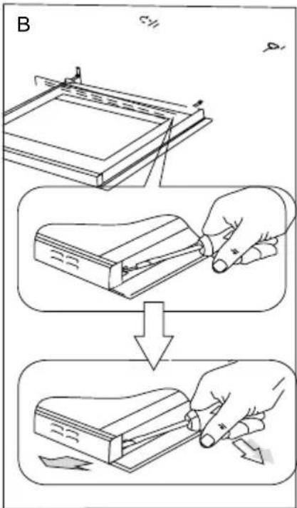
natural_image
Diagram of a device with two rectangular components, one showing a curved arrow and the other a grid-like structure (no text or symbols)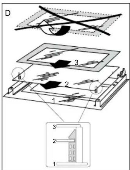
natural_image
Technical line drawings of two rectangular metal components with labeled parts (17 and 18), no text or symbols present.natural_image
Technical line drawing of a mechanical clamp or bracket (no text or symbols)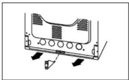
natural_image
Diagram of a mechanical component with arrows indicating motion or force direction (no text or symbols)RACCORDEMENT DE LA CUISINIÈRE SUR L'INSTALLATION DE GAZ
Attention!
natural_image
Pure diagram of a circular mechanical component with a central hub and arrow, no text or symbols present.natural_image
Pure mechanical component diagram without any text, numbers, or symbols
natural_image
Two circular diagrams with arrows indicating rotational direction, no text or symbols presentMAUVAIS BON
Attention!
REEMPLACEMENT DE L'AMPOULE DU FOUR
natural_image
Diagram showing three stages of a mechanical component with arrows indicating motion (no text or symbols)DÉMONTAGE ET MONTAGE DE LA PORTE DU FOUR
natural_image
Technical line drawing of a mechanical assembly with an inset showing a close-up of a component (no text or symbols present)
natural_image
Diagram of a rectangular device with internal components and a separate rack-mounted component (no text or symbols)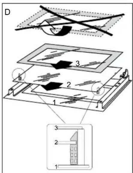
CONTRÔLE RÉGULIER
general terms and conditions of service and warranty
We do not need to remind you of the importance of service. After all, we develop our products to a standard so that you can enjoy them for many years, without any concerns. If, nevertheless, there is a problem, we believe you are entitled to a solution straight away. Hence our products come with an exchange service, on top of the rights and claims you are entitled to by law. By exchanging a product or part, we save you time, effort and costs.
2-year full manufacturer's warranty
- Customers enjoy a 2-year full manufacturer's warranty on all Inventum products. Within this period, a faulty product or part will always be exchanged for a new model, free of charge. In order to claim under the 2-year full manufacturer's warranty, you can either return the product to the shop you bought it from or contact the Inventum costumer service department via the form at www.inventum.eu/service-aanvraag.
- The 2-year warranty period starts from the date the product is bought.
- In order to claim under the warranty, you must produce a copy of the original receipt.
- The warranty applies only to normal domestic use of Inventum products within the Netherlands.
5-year Inventum warranty
- Inventum offers a 5-year warranty on most large domestic appliances and a selection of small domestic appliances. This 5-year Inventum warranty consists of a 2-year full manufacturer's warranty, extended by a further 3-year warranty. The only thing you need to do to qualify for the 3-year extended warranty is to register the product within 45 days of purchase. You can read more about registering the product in the following paragraph.
- In accordance with the 5-year Inventum warranty provisions, a faulty product or part will always be exchanged for a new model during the first 2 years under the warranty. During the 3rd to 5th year under the warranty, you will only pay the costs of exchange. The current costs of exchange are listed at www.inventum.eu/omruilkosten.
- In order to claim under the 5-year Inventum warranty, you can either return the product to the shop you bought it from or contact the Inventum costumer service department via the form at www.inventum.eu/service-aanvraag.
- The 5-year warranty period starts from the date the product is bought.
- In order to claim under the warranty, you must produce a copy of the original receipt.
- The warranty applies only to normal domestic use of Inventum products within the Netherlands.
Product registration
- The 3-year extended warranty is easy to obtain, free of charge, by registering the product within 45 days of purchase, via the website www.inventum.eu/garantie-registratie. If you did not register the product within 45 days of purchase, you can still do so up to 2 years after the purchase date. However, there will be a charge. The one-off registration charge is € 89 for each separate product. Registration is possible only for products that are subject to the 5-year Inventum warranty. Whether the product qualifies for the 5-year Inventum warranty is stated in the product user manual and in the product information sheet, on Inventum's website.
- The warranty period always starts from the date the product is bought. If the product is registered for the extended warranty at a later date, the warranty period still starts from the original date of purchase.
- The 3-year extended warranty can only be applied for if you are in the possession of a copy of the original receipt and the Inventum 5-year warranty certificate.
Large domestic appliances
- Breakdowns or faults in large domestic appliances (separate and built-in white goods) can be registered via the form at www.inventum.eu/service-aanvraag, by calling the Inventum costumer service department or in the store where you bought the device. The telephone number of the costumer service department can be found at www.inventum.eu.
- In the event of breakdowns or faults in large domestic appliances, Inventum will have the option to have a service engineer inspect the faulty device onsite at the customer in the Netherlands and to carry out repairs, there and then. The Inventum customer service department can also decide to have the device exchanged.
- If you suffer a breakdown or fault in a large domestic appliance during the first 2 years from the date of purchase, Inventum will not charge any costs for the exchange, call-out or for parts and labour.
- If you registered the product as described before at www.inventum.eu/garantie-registratie and you subsequently report a breakdown of a large domestic appliance in the 3rd to 5th year of the date of purchase, the 5-year Inventum warranty applies and the device will be repaired or exchanged, free of charge. In the event of a repair or exchange of the device, you only pay the costs of exchange. The current costs of exchange are listed at www.inventum.eu/omruilkosten. If you did not register the product, the 3-year extended warranty does not apply.
- When reporting a breakdown or fault, a service engineer will contact the customer within 1 working day in order to make an appointment. When the report is made in a weekend or during a public holiday, this will be the next working day.
- If you report a breakdown or fault via the form at www.inventum.eu/service-aanvraag, you will be kept informed of the progress via mobile messages and e-mail.
- The warranty period starts from the date the product is bought.
74 • English
- In order to claim under the warranty, you must produce a copy of the original receipt and the Inventum 5-year warranty certificate.
- The warranty applies only to normal domestic use of Inventum products within the Netherlands.
Breakdowns or faults outside the warranty period
- Breakdowns or faults in small or large domestic appliances outside the warranty period, can be reported to the costumer services department via the form at www.inventum.eu/service-aanvraag or by calling the costumer services department.
- The costumer services department may ask you to send the product for inspection or repair. The costs of dispatch will be at your expense.
- The inspection to establish whether repair is possible involves a charge. You need to grant your permission for this, in advance.
- In the event of a large domestic appliance, Inventum, at your request, can send out a service engineer. In that case, you will be charged the call-out costs, as well as parts and labour.
- In the event of an instruction to repair, the repair costs must be paid in advance. In the event of a repair by a service engineer, the costs of the repair must be settled with the engineer onsite, preferably by means of PIN payment.
Warranty exclusions
- The following is excluded from the aforesaid warranties:
• normal wear and tear;
- improper use or misuse;
• insufficient maintenance;
- failure to comply with the operating and maintenance instructions;
- unprofessional installation or repairs by third parties or the customer himself;
• non-original parts used by the customer;
- use for commercial or business purposes;
- removal of the serial number and/or rating label.
-
In addition, the warranty does not apply to normal consumer goods, such as:
-
dough hooks, baking tins, (carbon) filters, etc.;
- batteries, bulbs, carbon filters, fat filters etc.;
• external connection cables; - glass accessories and glass parts such as oven doors;
-
and similar items.
-
Transport damage not caused by Inventum is also excluded. Therefore, inspect your new device before starting to use it. If you detect any damage, you must report this to the store where you purchased the product within 5 working days, or to the Inventum customer service department via the form at www.inventum.eu/service-aanvraag. If transport damage is not reported within this period, Inventum does not accept any liability in this respect.
-
The following are excluded from warranty and/or replacement: faults, loss of and damage to the device as a result of an event that is normally insured under the home contents insurance.
Important to know
- The replacement or repair of a faulty product, or a part thereof, does not lead to an extension of the original warranty period.
- Parts that have been replaced, packaging material and exchanged devices are taken back by the service engineer and become the property of Inventum.
- If a complaint is unfounded, all costs arising from it will be at the customer's expense.
- Following expiry of the warranty period, all costs of repair or replacement, including administration costs, dispatch and call-out charges, will be charged to the customer.
- Inventum cannot be held liable for damage as a result of devices built in incorrectly.
- Inventum cannot be held liable for damage caused by external events, unless this liability arises from mandatory statutory provisions.
- These warranty and service provisions are governed by Dutch law. Disputes will be settled exclusively by the competent Dutch court.
facebook.com/inventum1908
youtube.com/inventum1908


- Deutsch
- HET FORNUIS AANSLUITEN OP DE GASINSTALLATIE
- Opgelet!
- OVENDEUR DEMONTEREN EN MONTEREN
- REGELMATIGE CONTROLE
- safety instructions
- appliance description
- • English
- before first use
- installation
- INSTALLING THE COOKER
- MOUNTING THE OVERTURNING PREVENTION BRACKET
- GAS CONNECTION
- Caution!
- Fitting guidelines
- Connection with a flexible steel hose
- Connection with a stable pipework
- ELECTRICAL CONNECTION
- ADAPTING THE COOKER TO ANOTHER TYPE OF GAS
- Exchange of a burner nozzle
- how to use the burners
- CHOICE OF COOKWARE
- CONTROL KNOBS FOR THE BURNERS
- Attention: always open the cover when using the cooker.
- 6
- operating the convection oven
- SWITCHING ON
- SWITCHING OFF
- • English
- baking tips and baking tables
- BAKING
- ROASTING MEAT
- ECO FAN HEATER
- 8
- cleaning and maintenance
- CLEANING THE GLASS COVER
- CLEANING THE COOKING PART
- PERSISTENT STAINS
- CLEANING THE OVEN
- ACCESSORIES
- REPLACING THE OVEN LIGHT BULB
- REMOVING AND REPLACING THE OVEN DOOR
- REMOVING AND REPLACING THE INNER GLASS PANEL
- REGULAR INSPECTIONS
- problems and solutions
- Achtung!
- AUSSCHALTEN
- RACCORDEMENT DE LA CUISINIÈRE SUR L'INSTALLATION DE GAZ
- Attention!
- REEMPLACEMENT DE L'AMPOULE DU FOUR
- DÉMONTAGE ET MONTAGE DE LA PORTE DU FOUR
- CONTRÔLE RÉGULIER
- general terms and conditions of service and warranty
- 2-year full manufacturer's warranty
- 5-year Inventum warranty
- Product registration
- Large domestic appliances
- • English
- Breakdowns or faults outside the warranty period
- Warranty exclusions
- Important to know
Brand : INVENTUM
Model : VFG5008WIT
Category : Cooker