
Next Evo X - Kettle Ariston Thermo - Free user manual and instructions
Find the device manual for free Next Evo X Ariston Thermo in PDF.


| Product Type | Electric Kettle |
| Brand | Ariston Thermo |
| Model | Next Evo X |
| Capacity | 1.7 Liters |
| Power Rating | 2200 Watts |
| Voltage | 220-240 V ~ 50/60 Hz |
| Dimensions (L x W x H) | 230 x 180 x 250 mm |
| Weight | 1.2 kg |
| Housing Material | Stainless Steel |
| Lid Type | Hinged with one-hand opening |
| Filter | Removable limescale filter |
| Base | 360° swivel cordless base |
| Water Level Indicator | Transparent window with scale |
| Control Type | On/off switch with indicator light |
| Main Functions | Fast boiling, auto shut-off, boil-dry protection |
| Safety Features | Auto shut-off, boil-dry protection, overheat protection |
| Maintenance | Descaling with vinegar or citric acid; clean with damp cloth |
| Spare Parts Availability | Replacement filter and base available |
| Reparability | Fuse and switch replaceable by qualified technician |
| Certifications | CE, RoHS |
Frequently Asked Questions - Next Evo X Ariston Thermo
User questions about Next Evo X Ariston Thermo
0 question about this device. Answer the ones you know or ask your own.
Ask a new question about this device
Download the instructions for your Kettle in PDF format for free! Find your manual Next Evo X - Ariston Thermo and take your electronic device back in hand. On this page are published all the documents necessary for the use of your device. Next Evo X by Ariston Thermo.
USER MANUAL Next Evo X Ariston Thermo
natural_image
Front view of a modern electric water heater with a digital display and control buttons (no text or symbols visible)
ARISTON
NEXT EVO X SFT
USER'S MANUAL INSTALLATION AND SERVICING INSTRUCTIONS
INSTANTANEOUS GAS WATER HEATER
User's manual
CE labelling ....3
General warnings ....4
Safety regulations....5
Control panel....7
Display....7
Ignition procedure....8
Water temperature adjustment 8
ECO mode....9
Switch-off procedure....9
Appliance shut-off conditions....10
Anti-freeze protection 11
Change gas type 11
Maintenance....11
Installation and servicing instructions
(Only for qualified technicians)....12
This product conforms to Directive WEEE 2012/19/EU.
The symbol of the crossed waste paper basket on the appliance indicates that at the end of its working life the product should be disposed of
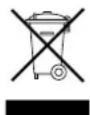
separately from normal domestic household rubbish, it must be disposed of at a waste disposal centre with dedicated facilities for electric and electronic appliances or returned to the retailer when a new replacement product is purchased.
The user is responsible for the disposal of the product at the end of its life at an appropriate waste disposal centre.
The waste disposal centre (which using special treatment and recycling processes effectively dismantles and disposes of the appliance) helps to protect the environment by recycling the material from which the product is made.
For further information about waste disposal systems visit your local waste disposal centre or the retailer from which the product was purchased.
Dear Customer,
Thank you for choosing an ARISTON gas water heater. We guarantee that your instantaneous water heater is a reliable and technically sound product.
This manual provides detailed instructions and recommendations for proper installation, use and maintenance.
Remember to keep this manual in a safe place for future reference i.e. by the gas meter.
Your local ARISTON Servicing Centre is at your complete disposal for all requirements.
WARNING!!

Water with a temperature higher than 50° cause serious burns.
Always verify water temperature before use.
IMPORTANT!

If the unit is installed in areas with the presence of hard water (> 200 mg / l) it is necessary to install a water softener to reduce the precipitation of limestone in the heat exchanger.
The warranty does not cover damage caused by the limestone.
WARNING!!

The device must be activated only in presence of water in the exchanger.
CE labelling
The CE mark guarantees that the appliance conforms to the following directives:
- 2016/426/EU relating to gas appliances
- 2014/30/EU relating to electromagnetic compatibility
- 2014/35/EU relating to electrical safety
- 2009/125/CE - Energy related Products
- 813/2013 - EU Regulation
This book (user's and installation manual) is an integral and essential component of the product.
Must be kept carefully by you and will always accompany the appliance in the event of its sale to another owner or user and / or transfer to another installation.
Carefully read the instructions and warnings contained in this manual as it contains important information about safe installation, operation and maintenance
This appliance is designed to produce hot water for domestic use.
It should be connected to a distribution network for domestic hot water that must be compatible with its performance and power levels.
The use of the appliance for purposes other than those specified is strictly forbidden. The manufacturer cannot be held responsible for any damage caused by improper, incorrect and unreasonable use of the appliance or by the failure to comply with the instructions given in this manual.
Installation, maintenance and all other interventions must be carried out in full conformity with the governing legal regulations and the instructions provided by the manufacturer.
Incorrect installation can harm persons, animals and possessions; the manufacturing company shall not be held responsible for any damage caused as a result.
In the event of a fault and/or malfunction, turn the appliance off, turn off the gas cock and do not attempt to repair it yourself. Contact a qualified professional instead.
Before any maintenance or repair work is performed on the appliance, make sure you have disconnected it from the electricity supply by switching the external bipolar switch to the "OFF" position and removing the fuse.
All repairs, which should only be performed using original spare parts, should be carried out by a qualified professional.
Failure to comply with the above instructions could compromise the safety of the appliance and invalidate all liability on the part of the manufacturer
In the event of any maintenance or other structural work in the immediate vicinity of the ducts or flue gas exhaust devices and their accessories, switch the appliance off by switching the external bipolar switch to the "OFF" position and shutting off the gas control valve.
When the work has been completed, ask a qualified technician to check the efficiency of the ducting and the devices.
If the appliance should be out of use for a prolonged period, it is recommended that the electrical power supply be disconnected and that the external gas cock be closed. If low temperatures are expected, the appliance and system pipe work should be drained in order to prevent frost damage.
When permanently deactivating the appliance, make sure that the operations are carried out by qualified technical professional.
Turn the appliance off and turn the external switch "OFF" to clean the exterior parts of the appliance.
No flammable items should be left or used in the vicinity of the appliance.
Do not allow children or inexperienced persons to use the appliance without supervision.
Safety regulations
Key to symbols:
Failure to comply with this warning implies the risk of personal injury, in some circumstances even fatal.
Failure to comply with this warning implies the risk of damage, in some circumstances even serious, to property, plants or animals.


Do not perform operations which involve opening the appliance.
Electrocution from live components.
Personal injury caused by burns due to overheated components, or wounds caused by sharp edges or protrusions.

Do not perform operations which involve removing the appliance from its installation space.
Electrocution from live components.
Flooding caused by water leaking from disconnected piping.

Explosions, fires or intoxication caused by gas leaking from disconnected piping.

Do not damage the power supply cable.
Electrocution from live uninsulated wires.

Do not leave anything on top of the appliance.
Personal injury caused by an object falling off the appliance as a result of vibrations.

Damage to the appliance or items underneath it caused by the object falling off as a result of vibrations.

Do not climb onto the appliance.
Personal injury caused by the appliance falling.

Damage to the appliance or any objects underneath it caused by the appliance falling away from its installation space.

Do not climb onto chairs, stools, ladders or unstable supports to clean the appliance.
Personal injury caused by falling from a height or cuts (stepladders shutting accidentally).

Do not attempt to clean the appliance without first switching it off and turning the external switch to the off position.
Electrocution from live components.

Do not use insecticides, solvents of aggressive detergents to clean the appliance.

Damage to plastic and painted parts.
Do not use the appliance for any use other than normal domestic use.
Damage to the appliance caused operation overload.

Damage caused to objects treated inappropriately.
Do not allow children or inexperienced individuals to operate the appliance.
Damage to the appliance caused improper use.

If you detect a smell of burning or smoke coming from the appliance, disconnect it from the electricity supply, turn off the main gas valve, open all windows and call for assistance.
Personal injury caused by burns, smoke inhalation, intoxication.

If there is a strong smell of gas, turn off the main gas valve, open all windows and call for assistance.
Explosions, fires or intoxication.

ATTENTION
This appliance can be used by children aged from 8 years and above and person with reduced physical, sensory or mental capabilities or lack of experience and knowledge if they have been given supervision or instruction concerning use of the appliance in a safe way and understand the hazards involved. Children shall not play with the appliance. Cleaning and user maintenance shall not be made by children without supervision.
WARNING
Installation, first ignition and maintenance work must be performed by qualified personnel only, in accordance with the instructions provided. Incorrect installation may harm individuals, animals or property; the manufacturer will not be held responsible for any damage caused as a result.
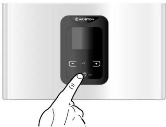
Control Panel
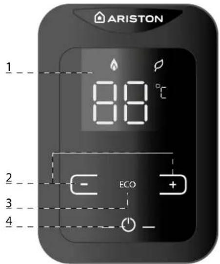
Key:
- Display
- Temperature Buttons
(Used to select hot water delivery temperature). - Energy saving button
- ON/OFF button
Display
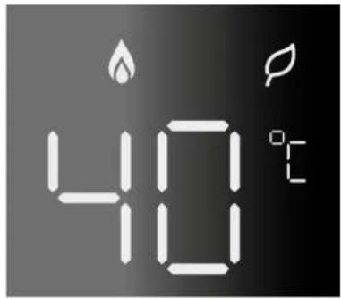
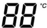
- Water set temperature indication (°C)
- Signal error codes

Flame presence signal

Energy saving signal
Ignition procedure
- ensure that the valve located on the cold water fitting is open
- ensure that the gas valve is open
- ensure that the device powered by electric current.
Press ON/OFF button "4", the display will light up.
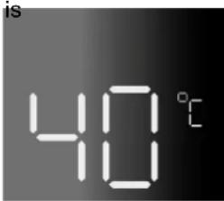
The device is ready to operate
The set temperature is indicated on the display.
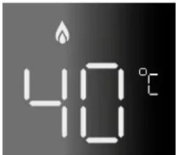
By opening the hot water valve, the device automatically starts operating.
The display shows the set temperature and the flame indicates the burner ignition.
WARNING!!

Water with a temperature higher than 50^ can cause serious burns.
Always verify water temperature before use.
Note: If the device does not operate, ensure that the gas and/or cold water valves are open.
Ensure that the device is electrically powered.
When closing the valve, the device automatically switches off and the flame symbol disappears from the display.
Water temperature adjustment
Press 📄 or 📋 to set the hot water temperature.
The new value will be indicated on the display
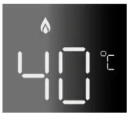
It's possible to increase the temperature up to 65 °C
To set the water temperature from 35 to 48 °C press the + button repeatedly. Pressing and releasing will trigger a rise of 1 degree Celsius.
From 48 to 65 °C see the table.
| T range D T setting | ||
| 35-48°C 1°C | Push + button | |
| 48-50°C 2°C | Push + button for 5 sec | |
| 50-55°C 5°C | C Push “+” button | |
| 55-60°C 5°C | C Switch OFF the machine and then push + button for 5 sec | |
| 60-65°C 5°C | Push + button | |
Child lock function
It's necessary switch OFF the appliance to reset the temperature range. Afterwards the temperature range will revert back to 35-48°C.
ECO mode
To activate the ECO mode press the button 3.
To increase or decrease the temperature press the button 2

When the ECO mode is activated the symbol appear on the dislay.
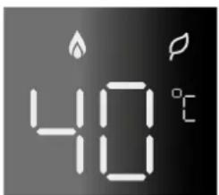
To exit from ECO mode is necessary to push the button 3 when the appliance is in stand-by mode.
Switching off procedure
Press the ON/OFF button, to switch off the appliance.
To switch off the completely, turn the outer electric switch in the off position. Close the gas valve.
Appliance shut-off conditions
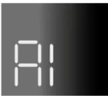
The appliance is protected from malfunctions by means of internal checks performed by the electronic P.C.B., which stops the appliance from operating if necessary. In case of shut-off a code appear on the display – see table below. To restore the system, turn the unit off and back on again.
Error table
| Error code | Description | |
| After pressing the ON / OFF button, the display turns off | - Check that the unit is electrically powered. | |
| A1 | No flame detected Ignition fault | - Check that the gas cock is open- Press the ON / OFF button. |
IF THE APPLIANCE WON'T START AGAIN OR STOPS REPEATEDLY, ONCE YOU'VE CARRIED OUT THE RELEVANT CHECKS, CLOSE THE GAS VALVE, TURN THE OUTER ELECTRIC SWITCH IN THE OFF POSITION AND CONTACT A QUALIFIED TECHNICIAN.
SHOULD THE ERROR NOT BE ELIMINATED, DO NOT ACTIVATE THE APPLIANCE.
Anti-freeze protection
Should the appliance be installed where pipes are subjected to freezing, it is recommended to empty it.
Proceed as indicated below:
- Turn the outer electrical switch to the OFF position
- Close the gas stopcock
- Close the cold water inlet valve
- Open the DHW valves until both the device and pipes are completely emptied.
To fill the device again, open the cold water inlet valve together with DHW valves until the water exits.
Disposal and recycling of the unit.
Our products are designed and manufactured for most of the components to be made of recyclable material.
The unit and its accessories have to be adequately disposed of and the various materials differentiated, where possible.
The packaging used for the transport of the unit must be disposed of by the installer / dealer.
ATTENTION!!
Recycling and disposal of the unit and the accessories must be made as required by regulations.
Change of gas type
Our instantaneous water heaters are designed to function either with Natural Gas (methane) or LPG gas. If you need to change from one gas to the other, one of our Authorised Service Centres must be contacted to convert the appliance.
Maintenance
Schedule an annual maintenance check-up for the appliance with a qualified person.
Correct maintenance always results in savings in the cost of running the system.
Failure to arrange an annual service for the appliance will invalidate the second year of the manufacturers warranty.
Installation and servicing instructions (Only for qualified technicians)
Overview.... 13
Advice for the installer 13
Safety regulations....14
Product description....20
Overall view....20
Overall dimensions....21
Installation....22
Before installing the appliance.... 22
Installation location....23
Minimum clearences.... 23
Gas connection.... 24
Water connection....24
View of hydraulic connections 24
Excessive pressure device....25
Water circuit diagram....26
Flue discharge/Air intake duct connections....27
Table of flue gas exhaust duct lengths 28
Type of air suction/flue gas exhaust ducting.... 28
Electrical connections....29
Electrical diagram....30
Commissioning....31
Ignition procedure....31
Electricity supply....31
Filling the hydraulic circuit 31
Gas supply.... 31
First Ignition....32
Checking the gas settings 33
Supply presure check....33
Checking the maximum/minimum burner pressure....33
Checking slow ignition power 34
Gas settings table....35
Gas conversion 35
Appliance protection devices.... 36
Table summarising error codes 36
Maintenance....37
Instructions for opening the casing and performing an internal inspection.... 37
General comments 38
Operational test 39
Draining procedures 39
Information for the user 39
Symbols used on the data plate 40
Technical data....41
ErP Data 42
Advice for the installer

The installation and first ignition of the appliance must be performed by qualified personnel in compliance with current national regulations regarding installation, and in conformity with any requirements established by local authorities and public health organisations.
This appliance is designed to produce hot water for domestic use.
It should be connected to a distribution network for domestic hot water that must be compatible with its performance and power levels.
The use of the appliance for purposes other than those specified is strictly forbidden. The manufacturer cannot be held responsible for any damage caused by improper, incorrect and unreasonable use of the appliance or by the failure to comply with the instructions given in this manual. Installation, maintenance and all other interventions must be carried out in full conformity with the governing legal regulations and the instructions provided by the manufacturer.
Incorrect installation can harm persons, animals and possessions; the manufacturing company shall not be held responsible for any damage caused as a result.
The appliance is delivered in a cardboard box. Once you have removed all the packaging, make sure the appliance is intact and that no parts are missing. If this is not the case, please contact your supplier.
Keep all packaging material (clips, plastic bags, polystyrene foam, etc.) out of reach of children as it may present a potential hazard.
In the event of a fault and/or malfunction, turn the appliance off, turn off the gas cock and do not attempt to repair it yourself. Contact a qualified professional instead.
Before any maintenance or repair work is performed on the appliance, make sure you have disconnected it from the electricity supply by switching the external bipolar switch to the "OFF" position and removing the fuse.
All repairs, which should only be performed using original spare parts, should be carried out by a qualified professional. Failure to comply with the above instructions could compromise the safety of the appliance and invalidate all liability on the part of the manufacturer.
In the event of any maintenance or other structural work in the immediate vicinity of the ducts or flue gas exhaust devices and their accessories, switch the appliance off by switching the external bipolar switch to the "OFF" position and shutting off the gas control valve.
When the work has been completed, ask a qualified technician to check the efficiency of the ducting and the devices.
Turn the appliance off and turn the external switch "OFF" to clean the exterior parts of the appliance.
Clean using a cloth dampened with soapy water. Do not use aggressive detergents, insecticides or toxic products. If the appliance is used in full compliance with current legislation, it will operate in a safe, environmentally-friendly and cost-efficient manner. If using kits or optional extras, make sure they are authentic.
WARNING!!

Water with a temperature higher than 50° cause serious burns.
Always verify water temperature before use.
WARNING!!
This appliance can be used by children aged 8 years and above and persons with reduced physical, sensory or mental capabilities or lack of experience and knowledge if they have been given supervision or instruction concerning use of the appliance in a safe way and understand the hazards involved. Children shall not play with the appliance. Cleaning and user maintenance shall not be made by children without supervision.
Safety regulations
Key to symbols:
Failure to comply with this warning implies the risk of personal injury, in some circumstances even fatal
Failure to comply with this warning implies the risk of damage, in some circumstances even serious, to property, plants or animals.


Install the appliance on a solid wall which is not subject to vibration.
Noisiness during operation.
When drilling holes in the wall for installation purposes, take care not to damage any electrical wiring or existing piping.
Electrocution caused by contact with live wires. Explosions, fires or asphyxiation

caused by gas leaking from damaged piping. Damage to existing installations.
Flooding caused by water leaking from damaged piping.

Perform all electrical connections using wires which have a suitable section.
Fire caused by overheating due to electrical current passing through undersized cables.

Protect all connection pipes and wires in order to prevent them from being damaged.
Electrocution caused by contact with live wires. Explosions, fires or asphyxiation

caused by gas leaking from damaged piping.

Flooding caused by water leaking from damaged piping.
Make sure the installation site and any systems to which the appliance must be connected comply with the applicable norms in force.
Electrocution caused by contact with live wires which have been installed incorrectly.

Damage to the appliance caused by improper operating conditions.

Use suitable manual tools and equipment (make sure in particular that the tool is not worn out and that its handle is fixed properly); use them correctly and make sure they do not fall from a height. Replace them once you have finished using them.
Personal injury from the falling splinters or fragments, inhalation of dust, shocks, cuts, pricks and abrasion

Damage to the appliance or surrounding objects caused by falling splinters, knocks and incisions.

Make sure any portable ladders are positioned securely, that they are suitably strong and that the steps are intact and not slippery and do not wobble when someone climbs them. Ensure someone provides supervision at all times.
Personal injury caused by falling from a height or cuts (stepladders shutting accidentally).

Make sure any rolling ladders are positioned securely, that they are suitably strong, that the steps are intact and not slippery and that the ladders are fitted with handrails on either side of the ladder and parapets on the landing.
Personal injury caused by falling from a height.

During all work carried out at a certain height (generally with a difference in height of more than two metres), make sure that parapets are used to surround the work area or that individual harnesses are used to prevent falls. The space where any accidental fall may occur should be free from dangerous obstacles, and any impact upon falling should be cushioned by semi-rigid or deformable surfaces.
Personal injury caused by falling from a height.

Make sure the workplace has suitable hygiene and sanitary conditions in terms of lighting, ventilation and solidity of the structures.
Personal injury caused by knocks, stumbling etc.

Protect the appliance and all areas in the vicinity of the work place using suitable material.
Damage to the appliance or surrounding objects caused by falling splinters, knocks and incisions.

Handle the appliance with suitable protection and with care.
Damage to the appliance or surrounding objects from shocks, knocks, incisions and squashing.

During all work procedures, wear individual protective clothing and equipment.
Personal injury caused by

electrocution, falling splinters or
fragments, inhalation of dust, shocks,
cuts, puncture wounds, abrasions, noise and vibration.
Place all debris and equipment in such a way as to make movement easy and safe, avoiding the formation of any piles which could yield or collapse.
Damage to the appliance or

surrounding objects from shocks,
knocks, incisions and squashing.
All operations inside the appliance must be performed with the necessary caution in order to avoid abrupt contact with sharp parts.
Personal injury caused by cuts,

puncture wounds and abrasions.
Reset all the safety and control functions affected by any work performed on the appliance and make sure they operate correctly before restarting the appliance.
Explosions, fires or asphyxiation caused by gas leaks or an incorrect flue gas exhaust.

Damage or shutdown of the appliance

caused by out-of-control operation.
Before handling, empty all components that may contain hot water, carrying out any bleeding if necessary.
Personal injury caused by burns.

Descale the components, in accordance with the instructions provided on the safety data sheet of the product used, airing the room, wearing protective clothing, avoid mixing different products, and protect the appliance and surrounding objects.
Personal injury caused by acidic substances coming into contact with skin or eyes; inhaling or swallowing harmful chemical agents.

Damage to the appliance or surrounding objects due to corrosion caused by acidic substances.

If you detect a smell of burning or smoke, keep clear of the appliance, disconnect it from the electricity supply, open all windows and contact the technician.
Personal injury caused by burns, smoke inhalation, asphyxiation.

Overall view
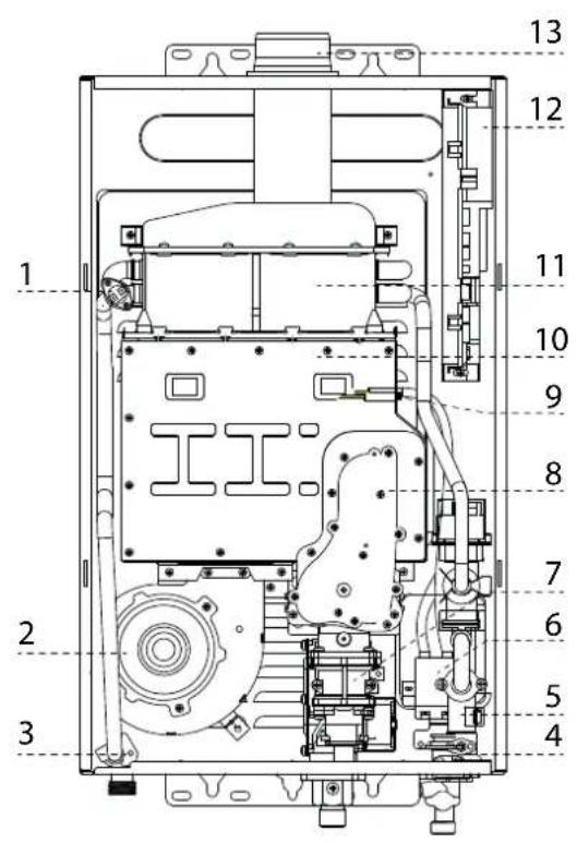
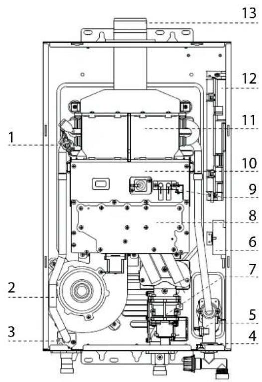
Legend
- Overheat thermostat
- Fan
- Water outlet temperature probe
- Water inlet temperature probe
- Water flow sensor
- Spark generator
- Gas valve
- Gas collector
- Ignition/Detection electrodes
- Combustion chamber
- Heat exchanger
- Control box
- Flue connector
Overall dimensions
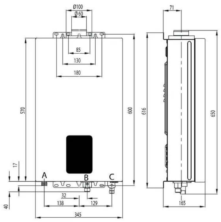
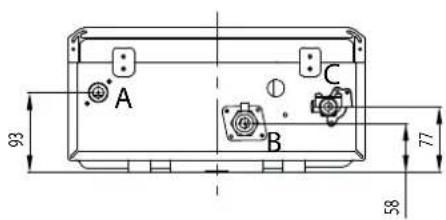
A. Hot water outlier 1/2"
B. Gas Inlet 1/2"
C. Cold water inlet 1/2"
G. Drain valve
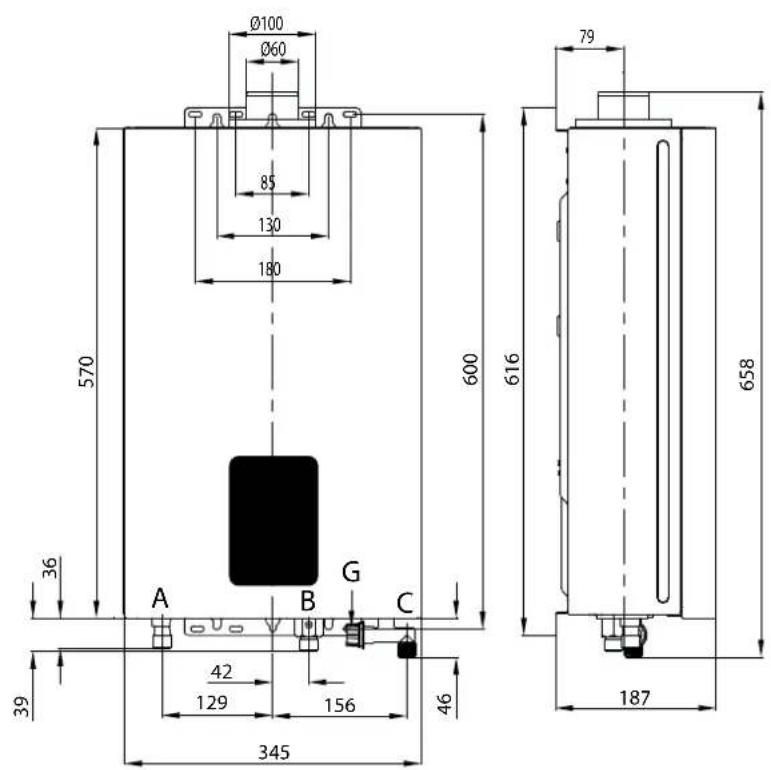
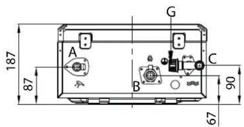
Before installing the appliance
The appliance heats water to a temperature below boiling. It should be connected to a domestic water mains supply. Before connecting the appliance, it is necessary to perform the following operations:
- Carefully wash the system piping in order to remove any screw thread or welding residues, or any dirt which might prevent the appliances from operating correctly.
- Make sure that the appliance is set up for operation with the type of gas available (read the information on the packaging label and on the boiler data plate).
- Make sure that there are no obstacles inside flue exhaust and that it does not contain any discharge from other appliances, unless the flue is meant to serve more than one user (in accordance with current legal requirements).
- Where there is already a connection to existing flue exhausts, check that these exhausts have been perfectly cleaned and are without residues, because any disconnection could obstruct the passage of fumes and create potentially dangerous situations.
- Make sure that, where unsuitable flue exhausts are attached, they have been ducted.
- In areas with particularly hard water, limescale may build up on the components inside the appliance and reduce its overall efficiency.
C-type appliance, with combustion chambers and air supply circuits which are completely sealed from the air outside, do not have any limitations concerning the ventilation and size of the room in which they are installed. So that the normal operation of the appliance is not compromised, the place in which it is installed must be suitable with regard to the operating limit temperature value and the appliance should be protected so that it does not come into direct contact with atmospheric agents.
The appliance must be installed on a solid, non-combustible, permanent wall to prevent access from the rear.
When creating a space for the boiler, the minimum distances (which ensure that various parts of the appliance may be accessed after it has been installed) should be respected.
WARNING

No flammable items should be left in the vicinity of the appliance.
Make sure the installation site and any systems to which the appliance must be connected are fully compliant with the current applicable legislation.
If dust and/or aggressive vapours are present in the room in which it is to be installed, the appliance must operate independently of the air inside the room.
WARNING

The installation and first ignition of the appliance must be performed by qualified personnel in compliance with current national regulations regarding installation, and in conformity with any requirements established by local authorities and public health organisations.
Installation location
Observe the regulations in force, when deciding where to install the device.
The device must not be installed near heat sources. Do not install the device in environments where temperatures may reach 0°C
For installation inside furniture, consider that the maximum temperature of the device jacket is lower than 85^ C and distances required for maintenance must be respected.
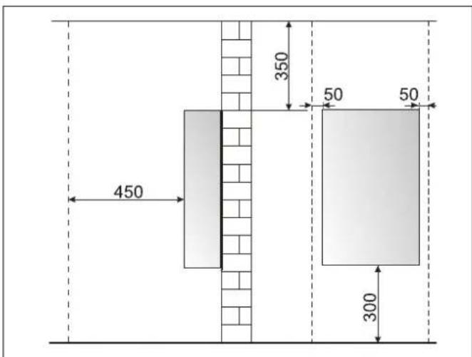
Minimum clearances
In order to allow easy access to the appliance for maintenance operations.
The appliance must be installed in accordance with the clearances stated below.
Gas connection
The appliance was designed to use gases belonging to the categories as shown in the following table.
| COUNTRY | MODEL CATEGORIES | |
| GB | NEXT EVO X 11 SFTNEXT EVO X 16 SFT | I3B/PII2H3P |
Make sure, using the labels on the packaging and the data plate on the appliance itself, that the appliance is in the correct country and that the gas category for which the appliance was designed corresponds to one of the categories available in the country where it will be used.
The gas supply piping must be created and measured out in compliance with specific legal requirements and in accordance with the maximum power of the appliance; you should also make sure that the shut-off valve is the right size and that it is connected correctly.
Before carrying out the installation, it is recommended that the fuel pipes are cleaned thoroughly in order to remove any residues which could prevent the appliance from operating correctly.
Check that the supplied gas corresponds to the type of gas for which the appliance was designed (see the data plate located on the appliance itself).
It is also important to check that the pressure of the gas (methane or LPG) you will be using to feed the appliance is suitable, because if it is insufficient the power of the generator may be reduced, causing inconvenience for the user.
Water connection
The illustration shows the connections for the water and gas attachments of the appliance.
Check that the maximum water mains pressure does not exceed 8 bar; if it does, a pressure reducing valve must be installed.
Ensure that the minimum pressure is not lower than 0,2 bar.
View of the hydraulic Connections
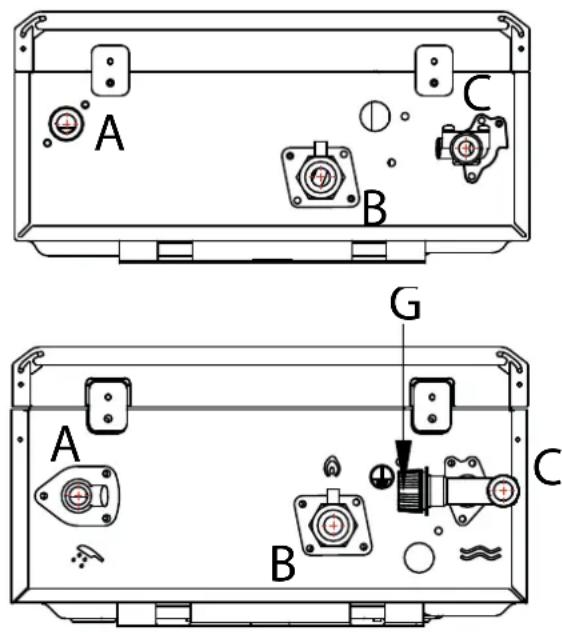
A. Hot water outlier 1/2"
B. Gas inlet 1/2"
C. Cold water inlet 1/2"
G. Drain valve
THE GAS WATER HEATER DOES NOT HAVE PRESSURE RELIEF FUNCTION. AN EXTRA PRESSURE RELIEF DEVICE IS NEEDED IF THIS FUNCTION IS NEEDED.
The device is equipped with a filter “G”, located on the cold water entrance. Periodically clean the hydraulic system, if dirt is present.
IMPORTANT!

DO NOT ACTIVATE THE DEVICE WITHOUT THE FILTER.
IMPORTANT!

IF THE UNIT IS INSTALLED IN AREAS WITH THE PRESENCE OF HARD WATER (> 200 MG / L) IS NECESSARY TO INSTALL A WATER SOFTENER TO REDUCE THE PRECIPITATION OF LIMESTONE IN THE HEAT EXCHANGER.
THE WARRANTY DOES NOT COVER DAMAGE CAUSED BY THE LIMESTONE.
Water circuit diagram
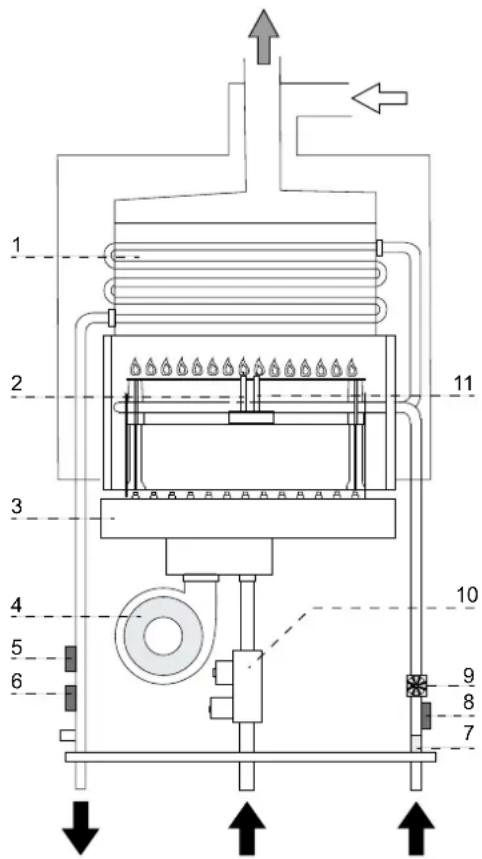
Key
- Heat exchanger
- Detection Electrode
- Burner
- Fan
- Outgoing water temperature sensor
- Overheat thermostat
- Cold water inlet filter
- Inlet water temperature probe
- Water flow switch
- Gas valve
- Ignition electrode
Flue discharge/Air intake duct connections
Intake/discharge flue duct installation must be in compliance with the regulation in force and instructions provided by the manufacturer
The appliance is designed to operate in C mode (by drawing air from outside).
When installing an exhaust system be careful when handling the seals, in order to avoid flue gas leaking into the air circuit.
Horizontally-installed piping must have a downward incline of 3% so as to avoid the build-up of condensate.
When implementing coaxial suction/exhaust systems the use of authentic accessories is obligatory.
The flue gas exhaust ducting must not be in contact with or placed near flammable materials, and must not cross building structures or walls made using flammable material.
The flue gas exhaust ducting joint should be created using a male/female coupling and a seal.
Couplings should always be arranged so that they go against the direction of the condensate flow.
For the calculation method, equivalent length values and installation examples please refer to the gas flue accessories catalogue.
The suction/exhaust ducting connection kits are supplied separately from the appliance, according to different installation solutions. Carefully read the instructions in the kit.
If there is any loss of pressure in the piping, please refer to the gas flue accessories catalogue. Supplementary resistance must be borne in mind during the sizing process mentioned above.
WARNING

MAKE SURE THAT THE FLUE GAS EXHAUST AND VENTILATION DUCTING ARE NOT OBSTRUCTED.
MAKE SURE THAT THERE ARE NO LEAKS ALONG THE FLUE GAS EXHAUST DUCTING.
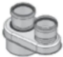
The appliance is set up for connection to a coaxial suction and flue gas exhaust ducting system (60/100).
The appliance is set up for connection to a 60/100 coaxial air intake and flue gas exhaust ducting system.
For split types of suction and exhaust, using the specified adapter.
natural_image
Simple 3D rendered mechanical component with two cylindrical parts mounted on a base (no text or symbols)Table of flue gas exhaust duct lengths
| Type | Maximum Extension Exhaust-air (m) | Pipes diameter (mm) | ||
| NEXT EVO X SFT 11/16 | ||||
| MIN MAX | ||||
| Coaxial system | C13 | 0,6 8 ø 60/100 | ||
| C33 | ||||
| Twin-pipe System | C13 | S1 = S2 | ø 80/80 | |
| C33 | 0,6 = 0,6 8 = 8 | |||
S1 = Air intake S2 = Flue gas exhaust
Type of air suction/flue gas exhaust ducting
| Combustion air intake from outside | ||
| C13 Flue gas exhaust and air suction duct through external wall in the same range of pressure | 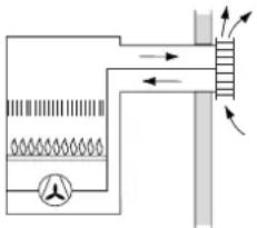 | |
| C33 Flue gas exhaust and air suction duct from outside with roof terminal in the same range of pressure | 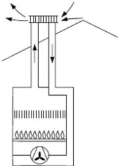 | |
WARNING
Before performing any work on the appliance, first disconnect it from the electrical power supply using the external bipolar switch.
Electrical connections
For increased safety, ask a qualified technician to perform a thorough check of the electrical system.
The manufacturer is not responsible for any damage caused by the lack of a suitable earthing system or by the malfunctioning of the electricity mains supply.
Make sure that the system is able to withstand the maximum power absorbed by the appliance (this is indicated on the appliance data plate).
Check that the section of the wires is suitable and is not less than 0,75 mm ^4
The appliance must be connected to an efficient earthing system if it is to operate correctly.
The power supply cable must be connected to a 230V-50Hz network, where the L-N poles and the earth connection are all respected.
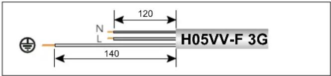
The use of multiplugs, extension leads or adaptors is strictly prohibited.
It is strictly forbidden to use the piping from the hydraulic, heating and gas systems for the appliance earthing connection.
The appliance is not protected against the effects caused by lightning. If the mains fuses need to be replaced, use 3.15A rapid fuses.
Important!
Connection to the electricity mains supply must be performed using a fixed connection (not with a mobile plug) and a bipolar switch with a minimum contact opening of 3mm must be fitted.
Electrical diagram
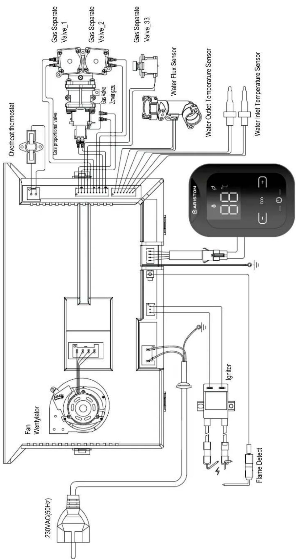
flowchart
graph TD
    A["230VAC(50Hz)"] --> B["Fan Wentylator"]
    B --> C["Overheat thermostat"]
    C --> D["Gas separate Valve_1"]
    C --> E["Gas separate Valve_2"]
    C --> F["Gas separate Valve_33"]
    D --> G["Water Flux Sensor"]
    E --> H["Water Outlet Temperature Sensor"]
    F --> I["Water Inlet Temperature Sensor"]
    J["Flame Detect"] --> K["Igniter"]
    K --> L["End"]
Ignition procedure
Press the ON/OFF key placed on the control panel, to display the set temperature.
For temperature adjustments see the User Manual paragraph.
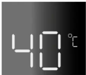
Initial procedures
To guarantee safety and the correct operation of the appliance, the appliance must be prepared for operation by a qualified technician who possesses the skills which are required by law.
Electricity supply
- Check that the voltage and frequency of the electricity supply correspond to the data shown on the appliance data plate;
- Make sure that the earthing connection is efficient.
Filling the hydraulic circuit
Proceed in the following manner:
- Gradually open the valve located on the cold inlet;
- open a D.H.W. tap.
WARNING!!
DO NOT USE THE APPLIANCE WITHOUT WATER.

Gas supply
Proceed in the following manner:
- Make sure that the main gas supply uses the same type of gas as indicated on the appliance data plate;
- Open all doors and windows;
- Make sure there are no sparks or naked flames in the room;
- Make sure that the system does not leak fuel using a cut-off valve inside the appliance itself which should be closed and then opened while the gas valve is disabled. The meter must not show any signs of gas being used for 10 minutes.
First ignition
The first start-up must be carried out by a qualified technician.
-
Make sure that:
-
The gas valve is closed;
- The electrical connection has been properly carried out. Make sure that, in any case, the green/yellow earthing wire is connected to an efficient earthing system;
-
The exhaust duct for combustion products should be suitable and free from any obstructions;
-
Switch on the appliance (by pressing the ON/OFF button)
- Open a D.H.W. tap.
- The appliance indicates the ignition lock failure
- Close the D.H.W. tap.
- To Restore the system, turn the appliance off and on again.
- Open the gas valve and check the connection seals, including the appliance connection seals, making sure that the meter does not detect any passage of gas. Eliminate any leaks.
- Start the appliance by opening a D.H.W. tap.
WARNING!!

Water with a temperature higher than 50^ can cause serious burns.
Always verify water temperature before use.
WARNING!!

Do not use the appliance without water.
Checking the gas settings
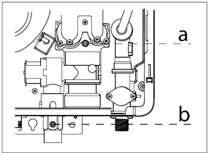
Supply pressure check
- Close the gas valve.
- Loosen screw "b" and insert the pressure gauge connection pipe into the pipe tap.
- Open the gas valve.
- Switch the appliance ON by opening a DHW tap. The supply pressure should correspond to the value established in relation to the type of gas for which the appliance is designed.
WARNING!!

Should the power pressure not correspond to what is indicated on the Gas Summary Table, DO NOT ACTIVATE THE DEVICE.
- Switch the appliance OFF by closing the DHW tap.
- Close the gas valve.
- When the check is over, tighten screw "b" and make sure it is securely in place.
- Open the gas valve and check the tightness of the screw.
Checking the maximum and minimum pressure (see the Gas setting table)
- Close the gas valve.
- Loosen screw "a" and insert the manometer connection pipe into the pipe tap.
- Open the gas valve.
- Press the On/Off button the display will illuminate.
- Open one hot water tap.
Simultaneously press the

and

buttons for
5 seconds. The display shows 26.
- Press the On/Off, appliance forced to maximum power. The display shows a number from "00" to "99".
-
On the manometer verify the pressure and if necessary press the ☐ and ☐(2) buttons to adjust maximum burner pressure as indicated on the gas settings table.
-
Press the On/Off, appliance forced to minimum power. The display shows a number from "00" to "99".
- On the manometer verify the pressure and if necessary press the □ and ▼ buttons to adjust minimum burner pressure as indicated on the gas settings table.
- Press the On/Off button to confirm.
- Close Hot water tap. Switch off the appliance through ON/OFF button.
- Tighten the connector screw tightly and check for leaks using a suitable device
Checking slow ignition power (see the Gas setting table)
- Close the gas valve.
- Loosen screw "a" and insert the manometer connection pipe into the pipe tap.
- Open the gas valve.
- Press the On/Off button the display will illuminate.
- Disconnect and reconnect the power supply.
- Press simultaneously press the ☐ or ☐(2) buttons
for 3 seconds. The display shows L6, plpliance forced to ignition power. Open one hot water tap.
- On the manometer verify the pressure and if necessary press the ☐ or ☐(2) buttons to adjust the slow ignition pressure as indicated on the gas settings table.
- Press the ON/FF button to save the change.
- Close Hot water tap. Switch off the appliance through ON/OFF button.
- Close Hot water tap. Switch off the appliance through ON/OFF button.
- Tighten the connector screw tightly and check for leaks using a suitable device
Gas setting table
| NEXT EVO X SFT 11 NEXT EVO X SFT 16 | ||||||||
| G20 G30 | G31 G20 | G30 G31 | ||||||
| Lower Wobbe index (15°C; 1013 mbares) MJ/m ^3 | 45.67 80.58 | 70.69 45.67 | 80.58 | 70.69 | ||||
| Gas inlet pressure mbar 20 | 28-30 | 37 20 | 28-30 | 37 | ||||
| Gas Burner Pressure MAX | mbar 1 | 2.10 12.60 | 15.90 9.5 | 10.8 | 12.50 | |||
| Gas Burner Pressure MIN | mbar | 3.0 | 3.0 | 3.0 | 2.5 | 2.5 | 2.5 | |
| Slow ignition pressure | mbar | 7.3 | 7.4 | 10.4 | 4.8 | 4.7 | 6.5 | |
| Parameter L - appliance capacity code | 11 | 11 | 11 | 16 | 16 | 16 | ||
| Parameter q - gas type code | 12 | 22 | 19 | 12 | 22 | 19 | ||
| Parameter F - appliance type code | 0 | 0 | 0 | 2 | 2 | 2 | ||
| Main Burner jets | 6X2 | 15x2 | ||||||
| ∅ burner jets | mm | 0.86 - 1.52 | 0.74 - 1.04 | 0.74 - 1.28 | 0.62 - 0.88 | |||
| Max/min consumption(15°C, 1013 mbar)(N.G.= m^3/h ) (LPG kg/h)) | MAX | 2.33 1.85 | 1.81 | 3.17 2.52 | 2.47 | |||
Gas conversion
The appliance may be adjusted so that it may be used with Liquid Gas (G30-G31) instead of methane gas (G20) or vice-versa. The adjustment must be performed by a Qualified Technician using the conversion Kit.
To modify the parameter proceed as follow:
- Switch Off the appliance, press the on/OFF button
- Disconnect and reconnect the power supply.
- Press ☐ and ☐ simultaneously for 3 seconds to access the parameters.
- Use the ON / OFF key to access the parameters, modify the parameters and save the changes made.
The parameters must be set as shown in the following table:
| NEXT EVO X SFT 11 NEXT EVO X SFT 16 | ||||||
| G20 G30 | G31 G20 | G30 G31 | ||||
| Parameter L - appliance capacity code | 11 | 11 | 11 | 16 | 16 | 16 |
| Parameter q - gas type code | 12 | 22 | 19 | 12 | 22 | 19 |
| Parameter F - appliance type code | 0 | 0 | 0 | 2 | 2 | 2 |
Appliance shut-off conditions
The appliance is protected from malfunctions by means of internal checks performed by the electronic P.C.B., which stops the appliance from operating if necessary.
In the event of the appliance being shut off in this manner, a code appears on the display which refers to the type of shut-off and the reason behind it.
Switch off the appliance. Make sure the external electric switch is in the OFF position, shut off the gas valve and contact a qualified technician.
Table summarising error codes
| Error code Description | ||
| A1 | Ignition fails - No flame detectedNo flame after safety time(3 attempts) | - Open the valve and follow the activation procedure- Check the ignition electrode- Check the detection electrodePress the ON/OFF to Reset |
| A2 | Overheating (overheat thermostat/thermo fuse) (95°C) | - A temperature higher than 95°C has been detected.Check the water pressurePress the ON/OFF to Reset |
| A3 | Flue pipe blockage | - Verify the air intake/exhaust fumes ductPress the ON/OFF to Reset |
| A4 | Flame lift (3 Times) during burning Press the | ON/OFF to Reset |
| A6 | Hot water temp. probe circuit open / short circuit | Replace water outlet temperature sensor or repair hardware circuit |
| A7 | Cold water temp. probe circuit open / short circuit | Replace water inlet temperature sensor or repair hardware circuit |
| E6 | Flame detected without gas ignition | Repair feedback needle or repair feedbackhardware circuit |
| E7 | Fan error | Replace the fan or repair the fan drive and speed detection hardware circuit |
| EE | Solar energy function fault protection The water inlet temperature exceeding 65°C | |
| TO | Parameter setting error protection | Error in parameter setting, please contact a qualified technician. |
Instructions for opening the casing and performing an internal inspection
Before performing any work on the appliance, first disconnect it from the electrical power supply using the external bipolar switch and shut off the gas valve.
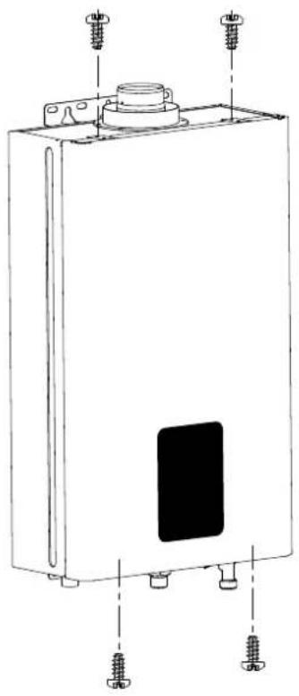
To access the inside of the appliance, the following is necessary:
- loosen the 4 screws,
- pull it forward and remove it.
natural_image
Technical line drawing of a rectangular electronic device with mounting screws and a central panel (no text or symbols)Maintenance is an essential part of the safe and efficient operation of the appliance and ensures its durability. It should be performed according to the instructions given in current legislation. Perform combustion analysis regularly in order to check the operating efficiency of the appliance and to make sure any polluting substances relaxed are within the boundaries set by current legislation.
Before beginning maintenance work:
- Disconnect the appliance from the electricity supply by turning the external bipolar switch to the "OFF" position;
- Close the gas valve and the central heating and domestic hot water system valve.
After the work has been completed the initial settings will be restored.
General comments
It is recommended that the following inspections be carried out on the appliance at least once a year:
- Check the seals in the water part and, if necessary, replace the gaskets and restore the seal to perfect working order.
-
Check the seals in the gas part and, if necessary, replace the gaskets and restore the seal to perfect working order.
-
Visually check the overall condition of the appliance.
-
Visually check the combustion and, if necessary, disassemble and clean the burner.
-
Following the inspection detailed in point "3", disassemble and clean the combustion chamber, if necessary.
-
Following the inspection detailed in point "4", disassemble and clean the burner and injector, if necessary.
-
Cleaning the primary heat exchanger
-
Make sure the following safety devices are operating correctly:
- temperature limit safety device.
- Make sure that the following gas part safety devices are operating correctly:
- absence of gas or flame safety device (ionisation).
-
Checking the efficiency of domestic hot water production (flow rate and temperature).
-
Cleaning the filter in cold water inlet.
WARNING! THE APPLIANCE MUST NOT BE PUT IN FUNCTION WITHOUT FILTER.
-
Perform a general inspection of the appliance operation.
-
Remove oxide from the detection electrode using an emery cloth.
Operational test
After having carried out the maintenance operations, fill the appliance and the water circuit.
- Begin operating the boiler.
- Check the settings and make sure all the command, adjustment and monitoring parts are working correctly.
- Check the seal and that the system for the expulsion of fumes/suction of comburent air is operating correctly.
- Check the settings and make sure all the command, adjustment and monitoring parts are working correctly. - Check the seal and that the system for the expulsion of fumes/suction of comburent air is operating correctly.
Draining procedures
The system must be drained using the following procedure:
- Close the inlet water valve;
- Open the hot and cold water taps;
- Empty the water from the lowest points of the system (where applicable).
- Close the inlet water valve; - Open the hot and cold water taps; - Empty the water from the lowest points of the system (where applicable).
WARNING
Before handling, empty all components which may contain hot water, performing bleeding where necessary.
Descale the components in accordance with the instructions provided on the safety data leaflet supplied with the product used, make sure the room is well ventilated, wear protective clothing, avoid mixing different products, and protect the appliance and surrounding objects.
Seal all openings used to take a gas pressure reading or to make any gas adjustments.
Make sure that the nozzle is compatible with the supplied gas.
If a smell of burning is detected or smoke is seen leaking from the appliance, or there is a smell of gas, disconnect it from the electricity supply, shut off the gas valve, open the windows and call for technical assistance.
Information for the user
Inform the user on how to operate the appliance.
In particular, provide the user with the instruction manuals and inform him/her that these must be stored with the appliance.
Moreover, make sure the user is aware of the following:
- How to set the temperature and adjustment devices for using the appliance correctly and in a more cost-efficient way.
- The system must be serviced regularly in compliance with legislation.
- The settings relating to the supply of combustion air and combustion gas must not in any event be modified.
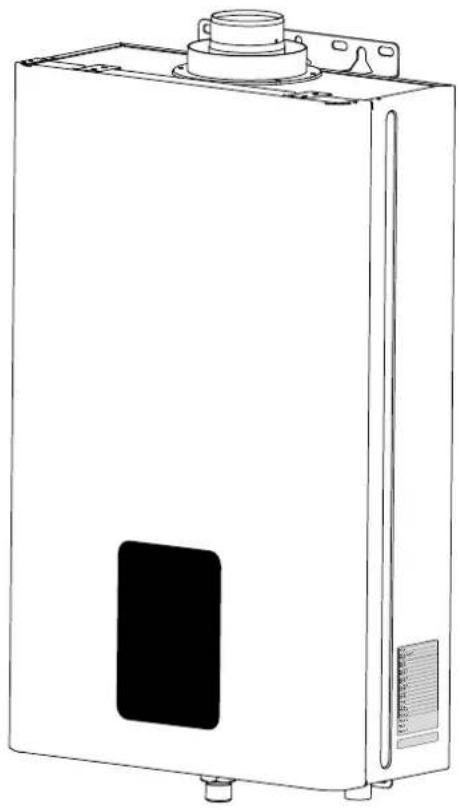
Symbols used on the data plate
| 1 |
| 2 |
| 3 |
| 4 |
| 5 |
| 6 |
| 7 |
| 8 |
| 9 |
| 10 |
| 11 |
| 12 |
| 13 |
| 14 |
| 15 |
| 16 |
| 17 |
| 18 |
| 19 |
| 20 |
Serial number
natural_image
Line drawing of a white rectangular electronic device with a central button and side ports (no text or symbols)Key:
- Brand
- IGWH model
- Commercial reference
- Certification number
- Gas category
- Input rating nominal heating max
- Power output heating max
- Input rating nominal heating min
- Power output heating min
- DHW specific flow rate
- Installation type
- Gases which may be used
- Max domestic hot water pressure
- Min domestic hot water pressure
15/16/17. Electrical data - Institution code
- Destination country
- Manufacturer
| Model name : NEXT EVO X 11 SFT 16 SFT | ||||
| CE Certification (pin) 0063CR7772 | ||||
| Type | C13 - C33 | |||
| Gas category II2H3P - I3B/P | ||||
| Maximum nominal heat input | kW 22.0 30.0 | |||
| Minimum nominal heat input | G20 kW 8.0 9.5 | |||
| G30 kW 8.0 9.5 | ||||
| G31 kW 7.0 8.5 | ||||
| Maximum nominal heat output G20 kW 19.2 27.4 | ||||
| G30 kW 19.2 27.8 | ||||
| G31 kW 19.3 27.8 | ||||
| Minimum nominal heat output G20 kW 7.4 8.7 | ||||
| G30 kW 7.4 8.9 | ||||
| G31 kW 6.4 7.9 | ||||
| Domestic hot water temperature maximum °C 65 65 | ||||
| Domestic hot water temperature minimum | °C 35 35 | |||
| D.H.W. Nominal flow rate | l/min | 11 | 16 | |
| D.H.W. minimum flow rate | l/min | 2.5 2.5 | ||
| Water pressure maximum | bar | 10 10 | ||
| Water pressure minimum | bar | 0.2 0.2 | ||
| Maximum flue gas flow | g/s | 15.77 | 24.02 | |
| Minimum flue gas flow | g/s | 9.68 | 13.95 | |
| Flue fumes temperature at Maximum nominal heat input | °C 158 | 120 | ||
| Flue fumes temperature at Minimum nominal heat input | °C 43 56 | |||
| ∅ Flue outlet & Air intake | 60/100 | 60/100 | ||
| Dimensions | ||||
| Height | mm | 570 | ||
| Width | mm | 345 | ||
| Depth | mm | 165 | 187 | |
| Power supply voltage/frequency | V/Hz | 230/50 | 230/50 | |
| Power consumption | W 29 44 | |||
| Internal fuse | 3.15 | |||
| Electric system grades of protection | IP | X4D | ||
| Minimum operating room temperature | °C | +5 | ||
| Dry weight | Kg | 13 15 | ||
ErP Data - EU 814/2013
| Model NEXT EVO X 11 SFT 16 SFT | |||
| Equivalent models list | see Annex A (*) | ||
| Declared load profile | M | XL | |
| Daily electricity consumption Q_elec | kWh | 0.044 | 0.064 |
| Daily Fuel Consumption Q_fuel | kWh | 7.804 | 24.845 |
| Indoor Sound power level L_WA | dB | 58 | 63 |
| Emission of Nitrogen Oxide NOx mg/kWh | 45 47 | ||
(*) For the list of equivalent models refer to Annex A, that is an integral part of this User's, Installation and Maintenance manual.
| PRODUCT FICHE - EU 812/2013 | |||
| Brand | [62AX] | [283Z] | |
| Model: NEXT EVO X | |||
| 11 SFT 16 | SFT | ||
| Declared load profile | M | XL | |
| Water heating energy efficiency class |  |  | |
| Water heating energy efficiency ηWH % 78.3 80.5 | |||
| Annual electricity consumption AEC kWh 10 14 | |||
| Annual fuel consumption AFC GJ | 6 | 19 | |
| Thermostat temperature setting | °C | 55 55 | |
| Indoor Sound power level LWA | dB | 58 63 | |
IMPORTANT!!
The products, without package label and package fiche for water heaters and solar devices, required by Regulation 812/2013, are not intended for use in these system.
The realisation of these systems is allowed using the kit code 3024085. In the kit are included package label and fiche.

ITALIAN DESIGN
ariston.com/uk


- NEXT EVO X SFT
- User's manual
- This product conforms to Directive WEEE 2012/19/EU.
- WARNING!!
- IMPORTANT!
- CE labelling
- Safety regulations
- Do not perform operations which involve opening the appliance.
- Do not perform operations which involve removing the appliance from its installation space.
- Do not damage the power supply cable.
- Do not leave anything on top of the appliance.
- Do not climb onto the appliance.
- Do not climb onto chairs, stools, ladders or unstable supports to clean the appliance.
- Do not attempt to clean the appliance without first switching it off and turning the external switch to the off position.
- Do not use the appliance for any use other than normal domestic use.
- Do not allow children or inexperienced individuals to operate the appliance.
- If there is a strong smell of gas, turn off the main gas valve, open all windows and call for assistance.
- ATTENTION
- WARNING
- Key:
- Ignition procedure
- Water temperature adjustment
- Child lock function
- ECO mode
- Switching off procedure
- Appliance shut-off conditions
- Anti-freeze protection
- Disposal and recycling of the unit.
- ATTENTION!!
- Change of gas type
- Maintenance
- Installation and servicing instructions (Only for qualified technicians)
- Overview.... 13
- Product description....20
- Installation....22
- Commissioning....31
- Appliance protection devices.... 36
- Maintenance....37
- Technical data....41
- Advice for the installer
- Overall view
- Legend
- Overall dimensions
- Before installing the appliance
- Installation location
- Minimum clearances
- Gas connection
- Water connection
- Water circuit diagram
- Key
- Flue discharge/Air intake duct connections
- Electrical connections
- Electrical diagram
- Initial procedures
- Electricity supply
- Filling the hydraulic circuit
- DO NOT USE THE APPLIANCE WITHOUT WATER.
- Gas supply
- First ignition
- The first start-up must be carried out by a qualified technician.
- Water with a temperature higher than 50° can cause serious burns.
- Always verify water temperature before use.
- Checking the gas settings
- Supply pressure check
- Checking the maximum and minimum pressure (see the Gas setting table)
- Checking slow ignition power (see the Gas setting table)
- Gas conversion
- Instructions for opening the casing and performing an internal inspection
- General comments
- WARNING! THE APPLIANCE MUST NOT BE PUT IN FUNCTION WITHOUT FILTER.
- Operational test
- Draining procedures
- Information for the user
- Symbols used on the data plate
- IMPORTANT!!
Brand : Ariston Thermo
Model : Next Evo X
Category : Kettle