
IM-UGC665 - Grill Napoleon - Free user manual and instructions
Find the device manual for free IM-UGC665 Napoleon in PDF.


| Product type | Built-in gas grill |
| Brand | Napoleon |
| Model | IM-UGC665 |
| Fuel type | Propane gas (LPG) or natural gas (NG) |
| Approximate dimensions (grill head) | Width: 91 cm (36 in), Depth: 61 cm (24 in), Height: 46 cm (18 in) |
| Approximate weight | Approximately 60 kg |
| Main materials | Stainless steel, porcelain-enameled cast iron |
| Tubular burners | 6 stainless steel tubular burners |
| Infrared burner | 1 ceramic infrared burner |
| Ignition | Electronic |
| Warranty | Limited lifetime 10-year president's warranty (see conditions) |
| Installation | Must be installed by a qualified gas installer in a non-combustible enclosure |
| Required ventilation | Minimum 150 mm (6 in) space at the back of the refrigerator |
| Maintenance and cleaning | Regular cleaning with non-abrasive products. Do not use oven cleaner. |
| Safety | Do not block vents; do not place the refrigerator next to the grill |
| Spare parts and repairability | Parts available at Napoleon dealers; requires model and serial number |
| Available accessories | 4 in spacing panel, 2 in end panel, optional propane tank cabinet |
| Color | Stainless steel |
| Standards | Compliant with CAN B149.1 (Canada) and ANSI Z223.1 (USA) standards |
| Usage | Outdoor, normal private use |
Frequently Asked Questions - IM-UGC665 Napoleon
User questions about IM-UGC665 Napoleon
0 question about this device. Answer the ones you know or ask your own.
Ask a new question about this device
Download the instructions for your Grill in PDF format for free! Find your manual IM-UGC665 - Napoleon and take your electronic device back in hand. On this page are published all the documents necessary for the use of your device. IM-UGC665 by Napoleon.
USER MANUAL IM-UGC665 Napoleon

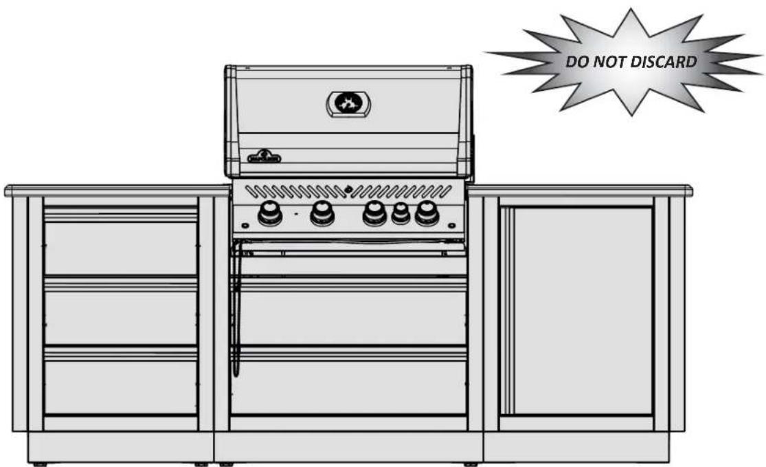
MODULAR CABINET ASSEMBLY INSTRUCTIONS
Use this manual in conjunction with your main manual to properly assemble your built-in grill. Refer to the main manual for operating, cleaning, and maintenance instructions. This grill is designed for NON-COMBUSTIBLE enclosures only, and must be installed and serviced by a qualified installer to local codes.
RETAIN THIS MANUAL FOR FUTURE REFERENCE.
Wolf Steel Ltd.
214 Bayview Drive,
Barrie, Ontario, CANADA L4N 4Y8
grills@napoleonproducts.com
N415-0416 APR 30.20
Wolf Steel Europe BV
Poppenbouwing 29-31, 4191 NZ Geldermalsen,
CCI No. 51509970, THE NETHERLANDS
info@napoleongrills.nl

www.napoleon.com
2
EN
Napoleon President's 10 Year Limited Warranty
NAPOLEON products are designed with superior components and materials, and are assembled by trained craftsmen who take great pride in their work. This product has been thoroughly inspected by a qualified technician before packaging and shipping to ensure that you, the customer, receive the quality product you expect from NAPOLEON.

NAPOLEON warrants that components in your new NAPOLEON product will be free from defects in material and workmanship from the date of purchase, for the following period:
Aluminum castings / stainless steel base 10 years
Stainless steel tube burners 10 years
Ceramic infrared burners (excluding screen) 5 years full coverage, plus 50% off until the 10th year
Stainless steel lid, door and drawer panels 5 years full coverage, plus 50% off until the 10th year
Porcelain-enameled cast iron cooking grids 5 years full coverage, plus 50% off until the 10th year
Stainless steel or porcelain sear plates 5 years full coverage, plus 50% off until the 10th year
Hinges, slides and enclosures 3 years full coverage, plus 50% off until the 10th year
All other parts 2 years
*Conditions and Limitations
This Limited Warranty creates a warranty period as specified in the aforementioned table, for any product purchased through an authorized NAPOLEON dealer, and entitles the original purchaser to the specified coverage in respect of any component replaced within the warranty period, either by NAPOLEON or an authorized NAPOLEON dealer, to replace a component of such product that has failed in normal private use as a result of a manufacturing defect. The "50% off" indicated in the table means the component is made available to the purchaser at a 50% discount off the regular retail price of the component for the period indicated. This Limited Warranty does not cover accessories or bonus items.
For greater certainty, “normal private use” of a product means that the product has been installed by a licensed, authorized service technician or contractor, in accordance with the installation instructions included with the product and all local and national building and fire codes; has been properly maintained; and has not been used as a communal amenity or in a commercial application.
Similarly, “failure” does not include: over-firing, blow outs caused by environmental conditions such as strong winds or inadequate ventilation, scratches, dents, corrosion, deterioration of painted and plated finishes, discoloration caused by heat, abrasive or chemical cleaners or UV exposure, chipping of porcelain enameled parts, or damages caused by misuse, accident, hail, grease fires, lack of maintenance, hostile environments such as salt or chlorine, alterations, abuse, neglect or parts installed from other manufacturers.
Should deterioration of parts occur to the degree of non-performance (rusted through or burnt through) within the duration of the warranted coverage, a replacement part will be provided. The replacement component is the sole responsibility of NAPOLEON defined by this Limited Warranty; in no event will NAPOLEON be responsible for installation, labor or any other costs or expenses related to the re-installation of a warranted part, for any incidental, consequential, or indirect damages or for any transportation charges, labor costs or export duties.
This Limited Warranty is provided in addition to any rights afforded to you by local laws. Accordingly, this Limited Warranty imposes no obligation upon NAPOLEON to keep parts in stock. Based on the availability of parts, NAPOLEON may at its discretion discharge all obligations by providing a customer a prorated credit towards a new product. After the first year, with respect to this Limited Warranty NAPOLEON may, at its discretion, fully discharge all obligations with respect to this warranty by refunding to the original warranted purchaser the wholesale price of any warranted but defective part(s).
The bill of sale or copy will be required together with a serial number and a model number when making any warranty claims from NAPOLEON.
NAPOLEON reserves the right to have its representative inspect any product or part prior to honoring any warranty claim. You must contact NAPOLEON Customer Service or an authorized NAPOLEON dealer to obtain the benefit of the warranty coverage.
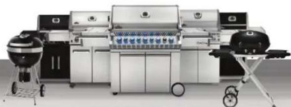
natural_image
Exterior view of a modern electric grill with mounted dishwashers and a portable gridded grill (no visible text or symbols)www.napoleon.com
PLANNING YOUR NAPOLEON MODULAR OUTDOOR ISLAND
With the Napoleon Outdoor Modular Islands, you can transform your backyard into a true barbecue oasis. The versatile modules can be arranged in a way that fits your grilling needs. The modules can be freestanding as an outdoor kitchen or mounted against a non-combustible wall.
The cabinets are designed to be easy to assemble and install by either the home owner or private contractor. Consider the following:
- All cabinets are 35" (889 mm) tall by 24" (610 mm) deep and 24" (610 mm) wide, except for the BUILT-IN grill cabinets whose width correspond to the width of the grill head unit it was designed for.
- The fridge cabinet has a removable panel which allows access to the temperature control located at the back of the fridge. Access to the panel must be ensured when the cabinet is installed.
• Each cabinet has 4 leveling feet for adjustment on even surfaces. - The 2 drawer cabinets are made to fit the Napoleon BUILT-IN series of grills only, which are available in different sizes. Grill head installation and operation instructions are detailed in the Owner's Manual that comes with it.
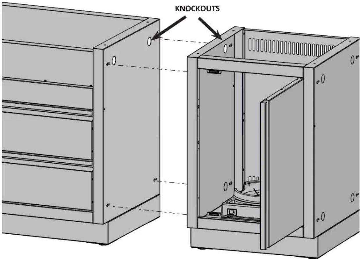
- The BUILT-IN series of grills can be ordered in either propane or natural gas configuration. Knockouts are present in the side and rear panels for easy piping and installation. For those who order a propane grill, a propane tank cabinet is available.
- The cabinets can be installed against a NON-COMBUSTIBLE wall of a house, a masonry or stucco half-wall, or freestanding in an island configuration.
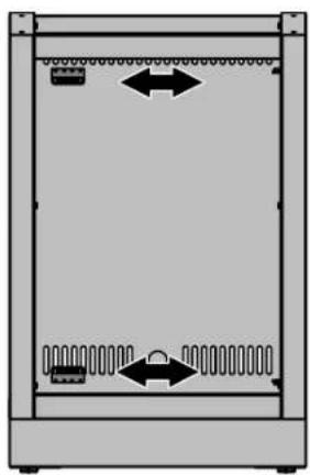
- Ensure there is adequate ventilation behind the fridge cabinet – a minimum gap of 6" (150 mm) is required between the back of the cabinet and adjacent structures.
- An optional 4" (102 mm) spacer panel can be purchased and installed to ensure enough clearance for the grill lid to open when installing against a wall. It also prevents debris or rodents from entering behind the cabinets.
- A powder-coated 2" (51 mm) wide end panel can be purchased to cover the knockouts and mounting holes in the outside panels in a run of cabinets, offering a finished look.
WARNING! All gas modifications and/or installations must be done by a qualified gas installer.
WARNING! Never block the vents located on the back of the fridge cabinet. Failure to do so can result in the fridge overheating.
WARNING! Never place the fridge and fridge cabinet next to the grill head and grill head cabinet.
It is recommended to use the false top-drawer module IM-2DC when:
- Doors and drawers get in the way of each other if placed next to a 450 or 900 transition.
- A drawer, door, or paper towel/garbage module is placed next to the grill and the control panel prevents them from fully opening and possible damages them.
- A side burner kit (optional through your Napoleon Gas Grill dealer), or a sink will be installed. The space behind the false drawer offers enough clearance for the side burner valve and hose routing and for the sink's piping.
Counter top: must be ordered and supplied locally by the homeowner.
- It must be made of NON-COMBUSTIBLE material for a grill to be installed into it.
- It can be ordered in advance by drawing out the cabinet's arrangement floor plan and adding up the width measurements, allowing 1-2 inches (25 mm - 51 mm) of counter top overhang.
TIP! Most counter top manufacturers are willing to come and take measurements after assembling the cabinets to ensure a perfect fit. Granite or Corian are recommended choices of counter top materials.
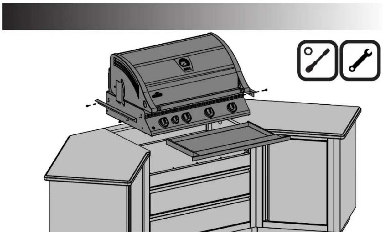
- For the drip pan to slide in and out properly, the grill head must be supported by a counter top with a thickness between 12 " (13 mm) and 112 " (38 mm).
- The built-in grill head comes with stainless steel brackets and hardware that allow the unit to rest on the counter top above the corresponding island cabinet.
Decorative counter tops made of ceramic tile set on top of cement tiling board can be made to match your surrounding backyard furniture colors.

WARNING! This product can expose you to chemicals including nickel, which are known to the State of California to cause cancer, and chemicals including bisphenol A, which are known to the State of California to cause birth defects or other reproductive harm. For more information go to www.P65Warnings.ca.gov.
4

TOOLS REQUIRED FOR ASSEMBLY (tools not included)

natural_image
Three black-and-white icons of wrenches, screwdriver, and plus sign inside rounded square frames (no text or symbols)3/8" (10mm)
GAS AND ELECTRICAL PIPING
The piping up to the gas grill is the responsibility of the installer and piping should be located as shown in the built-in instructions. Do not use hose to connect the unit. It must be connected with either rigid pipe, copper tube or an approved flexible metal connector. The installation must comply with CAN B149.1 Natural Gas and Propane installation code in Canada, or to the National Fuel Gas code, ANSI Z223.1 in the United States. The minimum recommended piping size is NPS 1/2" for rigid pipe, and 1/2" OD for copper tubing (based on a 20 ft run). Longer runs may require larger sizes to conform with CAN B149.1. Propane Gas Installation Code in Canada or to the National Fuel Gas Code, ANSI Z223.1 in the United States. Look to the manual that came with the gas grill for further instructions.
To ease installation and piping, removable knockouts have been provided in the side panels and in the center of each backpanel. The knockouts in the side panels should be removed before the cabinets are bolted in a row. Only remove the knockouts that are required for the piping of any gas, plumbing or electrical lines.
IM-UTC
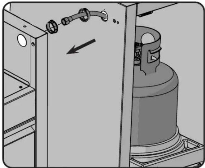
PROPANE SUPPLY HOSE ROUTING

x2
N105-0012
natural_image
Diagram of a gas cylinder inside a storage cabinet with pipe fittings, showing internal components and a directional arrow (no text or symbols)Knockouts have been punched in the sides and back panels to provide easy routing of gas or electrical piping. Once the knockout has been removed a bushing must be installed to prevent the gas or electrical line being cut on the edge of the hole. Gas piping and installation must be done by a qualified gas installer.
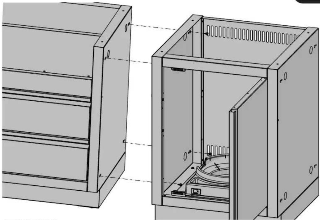
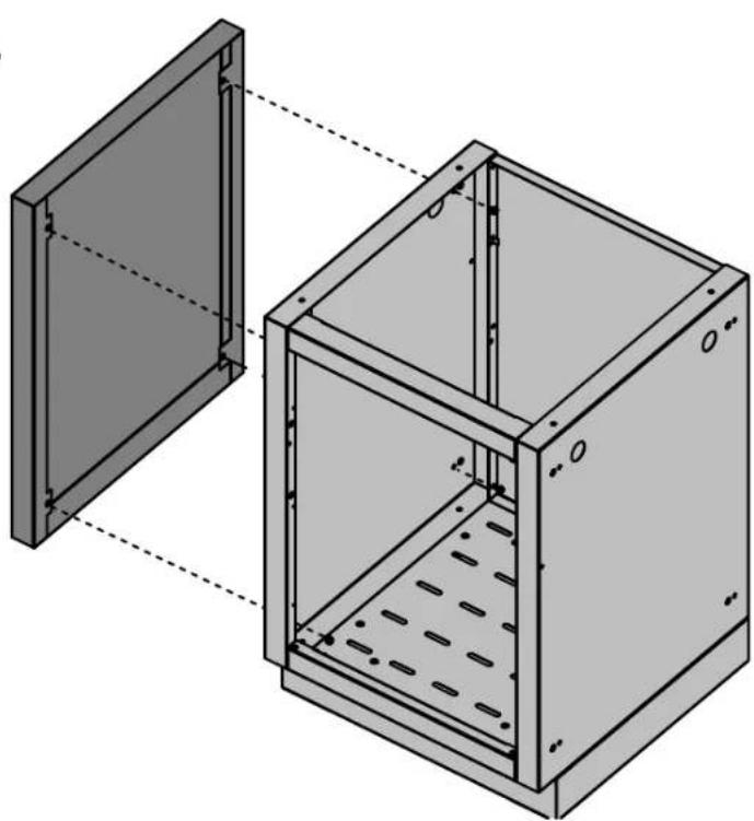
CABINET TO CABINET ASSEMBLY
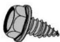
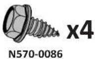
x4
N570-0086


natural_image
Technical line drawing of a mechanical cabinet with internal components and mounting holes (no text or symbols)N415-0416 APR 30.20
www.napoleon.com
EN
6
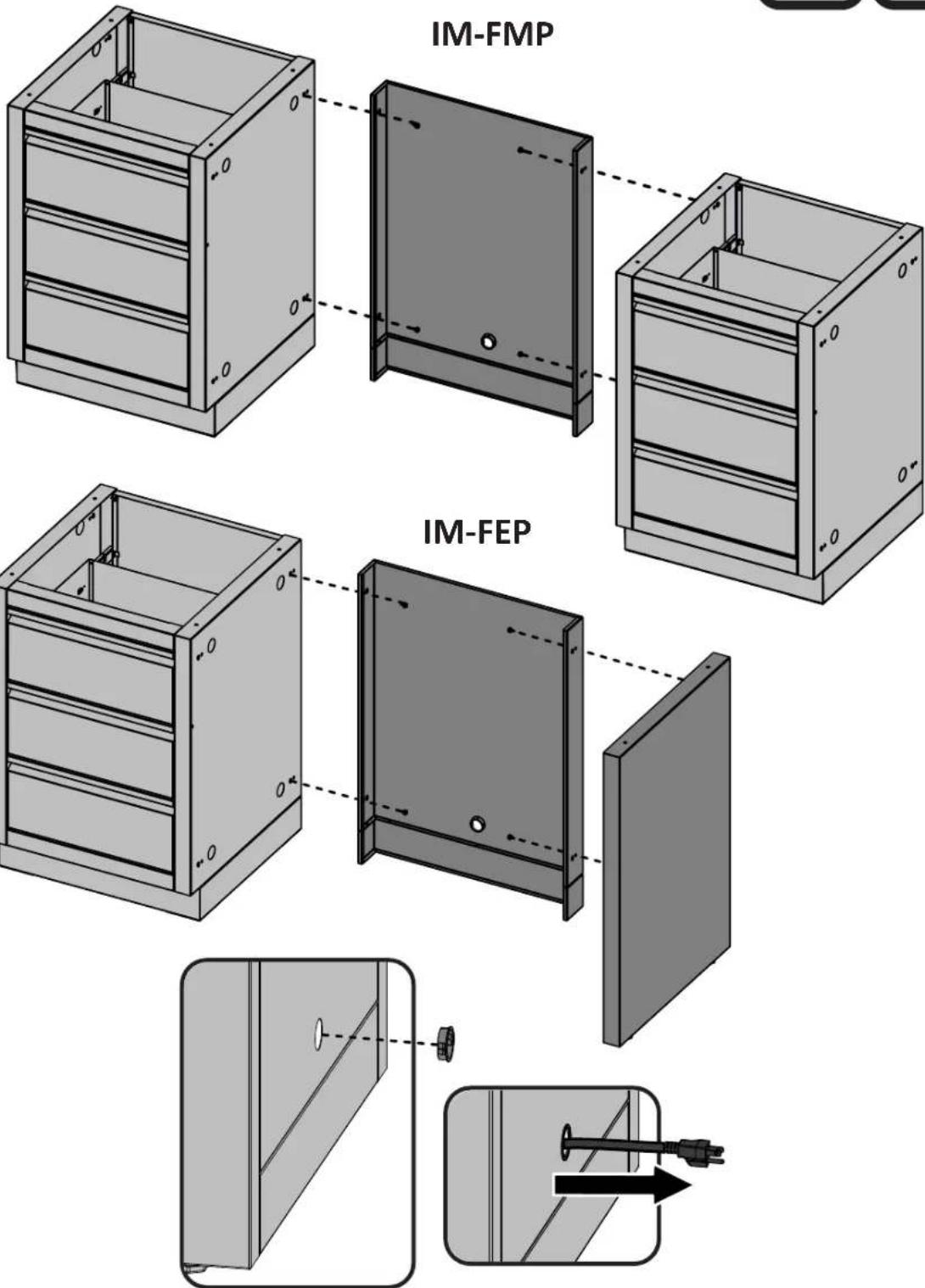
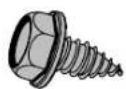
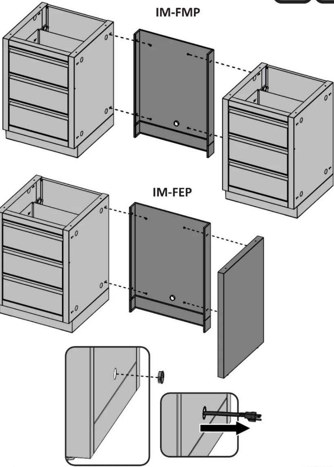
IM-FMP/FEP
FRIDGE PANEL ATTACHMENT
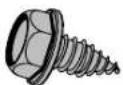
N570-0086
x4

N105-0012
x1


7
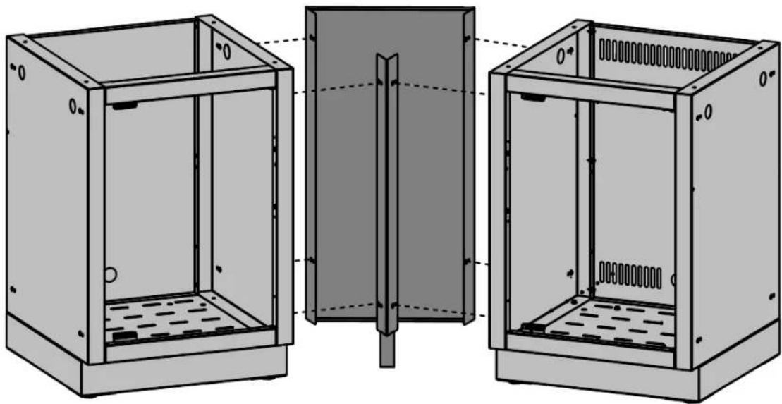
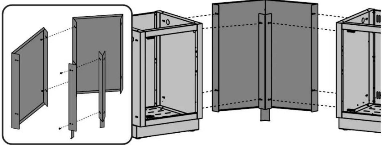
IM-45T CABINET 45 DEGREE CONNECTION
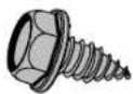
x8
N570-0086

natural_image
Two black square icons: a wrench and a screwdriver, no text or symbols present.EN
natural_image
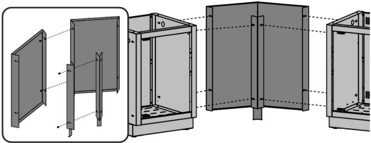
Technical line drawing of three views of a modular electrical enclosure with internal components (no text or symbols)IM-45T X 2 CABINET 90 DEGREE CONNECTION
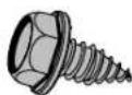
x12
N570-0086

natural_image
Technical diagram showing cross-sectional views of a mechanical assembly with no visible text or symbolsEN
8
IM-CEP
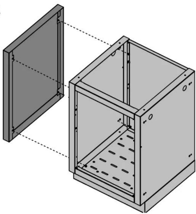
CABINET END PANEL KIT
natural_image
Technical illustration of a two-part mechanical housing with internal components and mounting holes (no text or symbols)
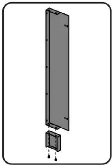
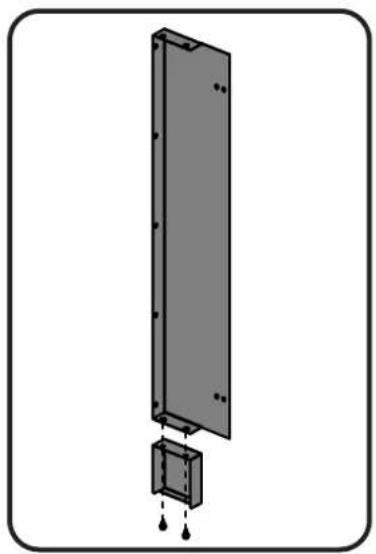
IM-CEP / IM-WSF CABINET END PANEL KIT
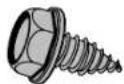
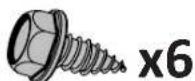
x6
N570-0086
natural_image
Diagram of a vertical panel with a small inset showing internal components (no text or symbols)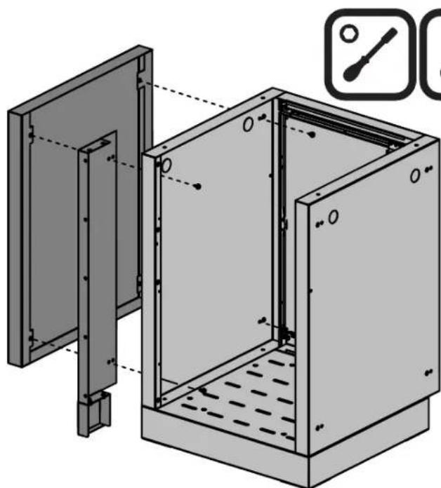
natural_image
Technical illustration of a mechanical assembly with mounting brackets and internal components (no text or symbols)
SHOWN WITH REAR PANEL REMOVED
9
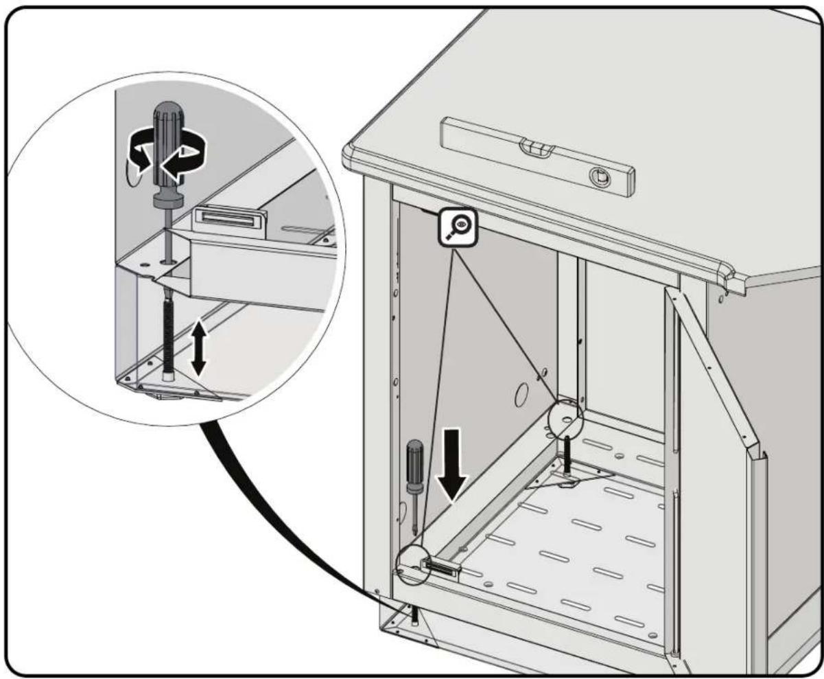
CABINET LEVELING PROCEDURE


natural_image
Technical diagram of a mechanical device with an inset showing a mechanical assembly and a close-up of the component (no text or symbols present)EN
10
natural_image
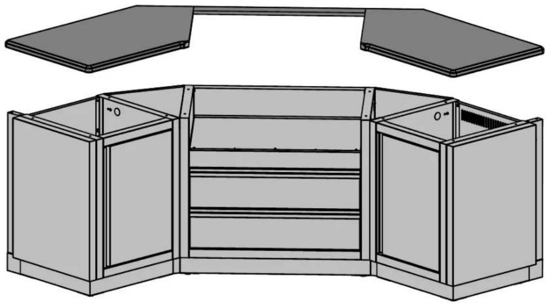
Technical line drawing of a cabinet or enclosure structure with two top panels and internal compartments (no text or symbols)COUNTERTOP TO BE FASTENED AS PER MANUFACTURER'S INSTRUCTIONS. HOLES HAVE BEEN PLACED ON THE TOP FLANGE OF THE SIDE PANELS TO ALLOW FOR FASTENERS.

natural_image
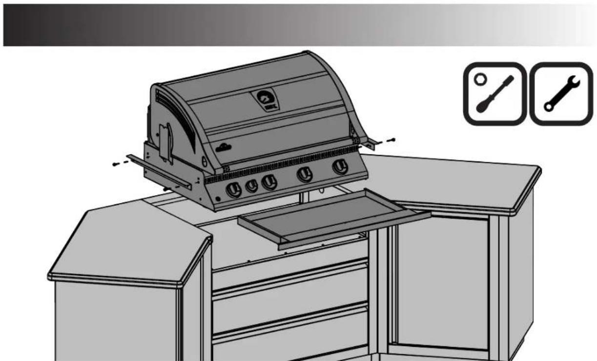
Line drawing of a gas stove with menu and tools, no text or symbols presentREFER TO BUILT-IN MANUAL THAT ACCOMPANIES THE GRILL FOR COMPLETE INSTRUCTIONS. GAS PIPING MUST BE DONE BY A LICENSED GAS INSTALLER.
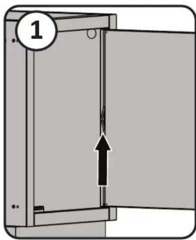
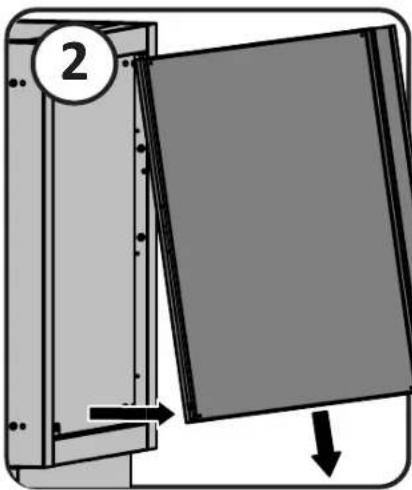
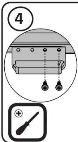
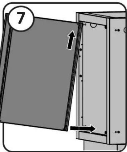
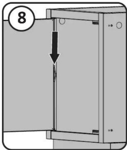
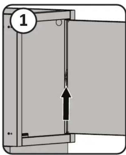
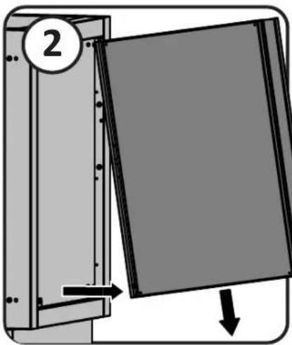
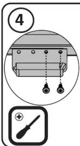
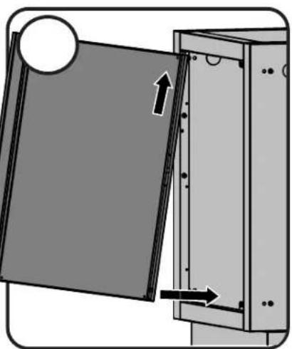
DOOR REVERSAL
natural_image
Diagram of a door mechanism with directional arrows indicating movement (no text or symbols)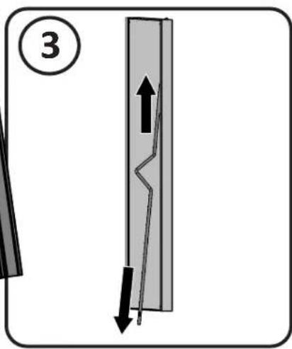
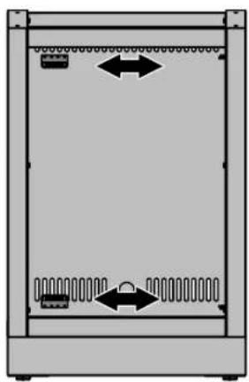
natural_image
Diagram of a server rack with ventilation slots and directional arrows indicating movement (no text or symbols)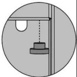
natural_image
Simple circular diagram showing a suspended object with a vertical line and a rectangular base, no text or symbols present.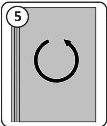
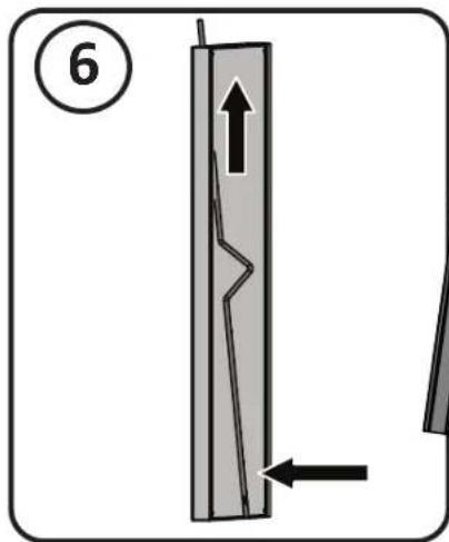
12
EN
Notes
KEEP YOUR RECEIPT AS PROOF OF PURCHASE TO VALIDATE YOUR WARRANTY.
Ordering Replacement Parts
Warranty Information
MODEL:
DATE OF PURCHASE: ____
SERIAL NUMBER:
(Record information here for easy reference)
For replacement parts and warranty claims, contact the Napoleon dealer where the product was purchased.
Before contacting the dealer, check the Napoleon Grills Website for more extensive cleaning, maintenance, troubleshooting and parts replacement instructions at www.napoleon.com.
To process a claim, the following information is required:
- Model and serial number of the unit.
- Part number and description.
- A concise description of the problem ('broken' is not sufficient).
- Proof of purchase (photocopy of the invoice).
In some cases, Napoleon could request to have the parts returned to the factory for inspection before providing replacement parts.
Before contacting Napoleon dealer, please note that the following items are not covered by the warranty:
• Costs for transportation, brokerage or export duties.
- Labour costs for removal and reinstallation.
- Costs for service calls to diagnose problems.
• Discolouration of stainless steel parts.
- Part failure due to lack of cleaning and maintenance, or use of improper cleaners (oven cleaner or other harsh chemicals).


INSTRUCTIONS D'ASSEMBLAGE DES CABINETS MODULAIRES
natural_image
Exterior view of a modern electric grill with two large grilles and a portable stove (no visible text or symbols)www.napoleon.com
PLANIFICATION DE VOTRE ÎLOT MODULAIRE EXTÉRIEUR NAPOLÉON
natural_image
Three black-and-white icons of wrenches, screwdriver, and plus button symbols inside rounded squares (no text or labels)3/8" (10mm)
INSTALLATION DE L'ALIMENTATION ÉLECTRIQUE ET DE LA TUYAUTERIE POUR LE GAZ
natural_image
Technical illustration of a gas cylinder mounted on a cabinet, showing pipe connections and structural components (no text or symbols)natural_image
Technical line drawing of a mechanical housing assembly showing internal components and mounting features (no text or symbols)N415-0416 APR 30.20
www.napoleon.com
18
IM-FMP/FEP PANNEAU D'ATTCHE DE REFRIGERATEUR
FR
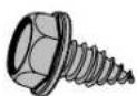
N570-0086
x4

N105-0012
x1


IM-45T RACCORDEMENT DE CABINETS À 45 DEGRÉS
x8
N570-0086

natural_image
Two black square icons: a wrench and a wrench, both without any text or symbols.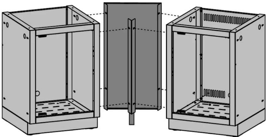
natural_image
Technical line drawing of three views of a cabinet or enclosure with internal components, showing structural details (no text or symbols)FR
IM-45T X 2 RACCORDEMENT DE CABINETS À 90 DEGRÉS
x12
N570-0086

natural_image
Technical diagram showing cross-sectional views of a mechanical or electrical enclosure with no visible text or symbols20
IM-CEP ENSEMBLE DE PANNEAU D'EXTRÉMITÉ
FR
natural_image
Isometric technical drawing of a two-story metal enclosure with internal structure and mounting holes (no text or symbols)
natural_image
Two black-and-white icons of wrenches, one with a circular head and the other with a wrench (no text or symbols)IM-CEP / IM-WSF ENSEMBLE DE PANNEAU D'EXTRÉMITÉ
N570-0086
natural_image
Diagram of a vertical panel with a small inset showing internal components (no text or symbols)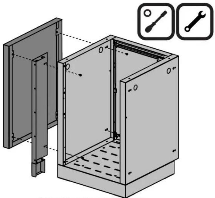
natural_image
Technical illustration of a modular electrical enclosure with two tool icons (扳 and wrench) shown in the corner, no text or symbols present.ILLUSTRÉ SANS LE PANNEAU ARRIÈRE
www.napoleon.com
N415-0416 APR 30.20
MISE DE NIVEAU DU CABINET
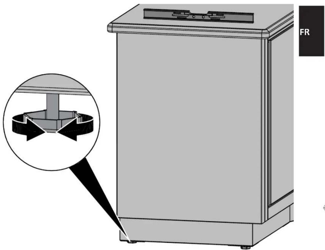
natural_image
Technical illustration of a mechanical device with a magnified inset showing internal components (no text or symbols)22
FR

natural_image
Simple 3D diagram of two rectangular blocks connected by a horizontal line (no text or symbols)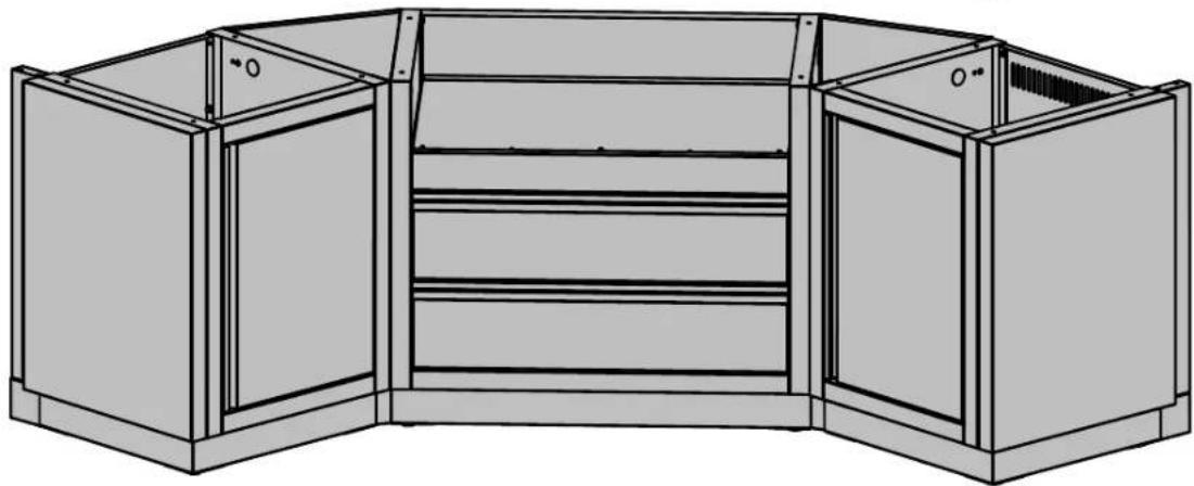
natural_image
Technical line drawing of a cabinet or storage unit with multiple doors and drawers (no text or symbols)FIXEZ LE COMPTOIR EN RESPECTANT LES DIRECTIVES DU FABRICANT. DES TROUS ONT ÉTÉ MÉNAGÉS DANS LE REBORD SUPÉRIEUR DES PANNEAUX LATÉRAUX POUR Y INSÉRER LES PIÈCES DE FIXATION.

natural_image
Illustration of a portable gas stove with menu and storage unit, accompanied by icons for tools (no text or symbols on main diagram)POUR DES DIRECTIVES COMPLÈTES, CONSULTEZ LE MANUEL QUI ACCOMPAGNE LE GRIL ENCASTRÉ.LA TUYAUTERIE POUR LE GAZ DOIT ÊTRE INSTALLÉE PAR UN INSTALLATEUR POUR LE GAZ AUTORISÉ.
PORTE INVERSE
natural_image
Diagram of a door mechanism with labeled component 2 and directional arrows indicating movement (no text or symbols beyond labels)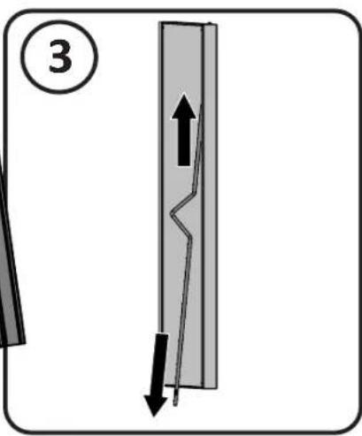
FR
natural_image
Diagram of a server rack with ventilation slots and directional arrows indicating movement (no text or symbols)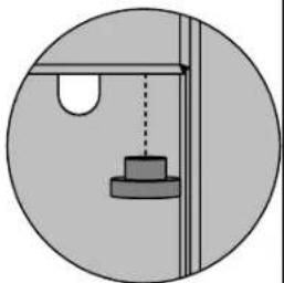
natural_image
Simple circular diagram showing a suspended object with a vertical line and a rectangular base, no text or symbols present.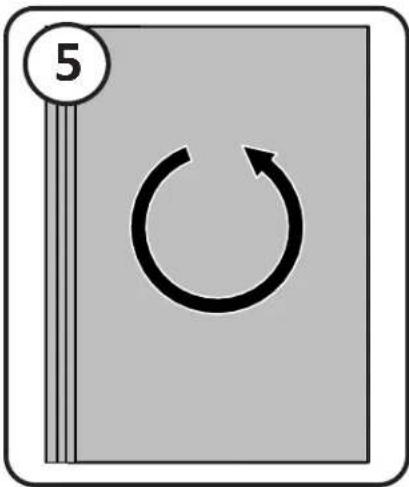
natural_image
Simple diagram with a circular number 5 and a circular arrow symbol inside a square frame (no text or labels)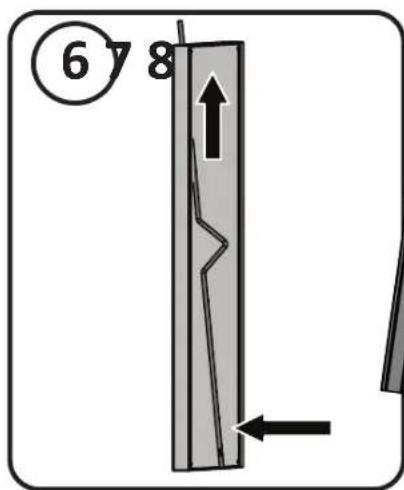
natural_image
Diagram of a mechanical assembly with a circular component and directional arrows indicating movement (no text or symbols)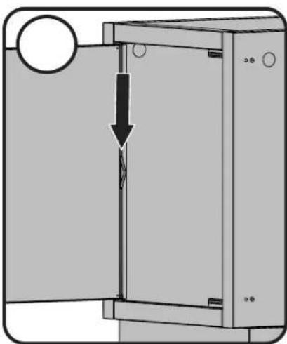
natural_image
Diagram of a mechanical device with a downward arrow indicating a cut or dissection (no text or symbols present)GARDEZ VOTRE REÇU COMME PREUVE D'ACHAT POUR VALIDER VOTRE
| # Part # Description IM-UDC | |||
| 1 N475-0223-CN1HR side panel | panneau avant x | ||
| 2 N475-0224-CN1HR back panel | panneau arrière x | ||
| 3 N570-0086 #14 x 1/2" screw / vis #14 x 1/2" x | |||
| 4 NC10-0575-CN1HR bottom sho | f assembly / ensemble de tablette inférieur x | ||
| 5 N570-0130 leveling foot / mise à niveau du pied x | |||
| 6 N525-0018-CN1HR top/bottom rail / support superior/inférieur x | |||
| 7 N105-0011 door bushing / bagues de porte x | |||
| 8 N555-0023 | door pivot rod / tige-pivot de porte | x | |
| 9 NC10-0590 door assembly / en | semble de porte x | ||
| 10 N430-0002 | magnetic catch / loquet magnétique | x | |
| 11 N080-0232-CN1HR door magnet bracket / support de magnétique x | |||
| 12 N570-0013 #8 x 5/8" screw / vis #8 x 5/8" x | |||
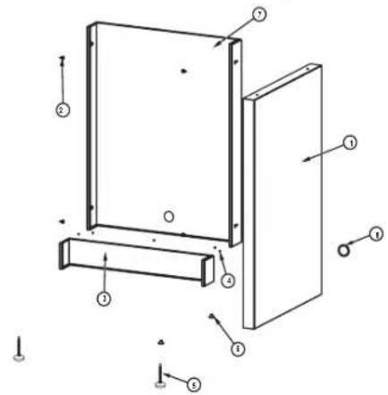
| # | Part # | Description | IM-FMP | IM-FEP |
| 1 | N475-0404-CN1HR | side panel / panneau avant | x | |
| 2 | N570-0086 | #14 x 1/2" screw / vis #14 x 1/2" | x | x |
| 3 | N525-0055-CN1HR | bottom rail / support inférieur | x | x |
| 4 | N545-0005 | rivet / rivet | x | x |
| 5 | N570-0130 | leveling foot / mise à niveau de pied | x | |
| 6 | N450-0046 nut / écrou | x | ||
| 7 | N475-0403-CN1HR | back panel / panneau arrière | x | x |
| 8 | N105-0012 | 1.5" bushing / bagues de porte 1.5" | x | x |
| # | Part # | Description | IM-UTC |
| 1 | N475-0223-CN1HR | side panel / panneau avant | x |
| 2 | N475-0237-CN1HR | back panel / panneau arrêté | x |
| 3 | N570-0086 | screw, #14 x 1/2" / vis #14 x 1/2" | x |
| 4 | N010-0575-CN1HR | assembly bottom shelf / ensemble de tablette inférieur | x |
| 5 | N570-0130 | leveling foot / mise à niveau du pied | x |
| 6 | N525-0018-CN1HR | top/bottom rail / support superior/inférieur | x |
| 7 | N105-0011 | door bushing / bagues de porte | x |
| N105-0012 | 1.5" bushing / bagues de porte 1.5" | x | |
| 8 | N555-0023 | door pivot rod / tige-pivot de porte | x |
| 9 | N010-0590 | door assembly / ensemble de porte | x |
| 10 | N430-0002 | magnetic catch / loquet magnétique | x |
| 11 | N080-0232-CN1HR | door magnet bracket / support de magnétique | x |
| 12 | N570-0013 | #8 x 5/8" screw / vis #8 x 5/8" | x |
| 13 | N010-0938 | tank tray/ plateau de réservoir | x |
| 14 | N010-0095-CN1HR tank tray support / support de bac à réservoir x | ||
N415-0416 APR 30.20
www.napoleon.com
| # | Part # | Description | IM-UTC-CE |
| 1 | N010-0575-CN1HR | assembly, bottom shelf / ensemble de tablette inférieur | x |
| 2 | N010-1154 | assembly tank tray slide / assy plateau rail support | x |
| 3 | N010-1153-CN1HR | tank tray CE grey / plateau du bonbonne CE gris | x |
| 4 | N475-0223-CN1HR | side panel / panneau avant | x |
| 5 | N475-0237-CN1HR | back panel / panneau arrière | x |
| 6 | N525-0018-CN1HR | top/bottom rail / support superior/inférieur | x |
| 7 N570-0086 | screw , #14 x 1/2" / vis #14 x 1/2" | x | |
| 8 N010-0590-CN | door assembly / ensemble de porte | x | |
| 10 | N555-0023 | door pivot rod / tige-pivot de porte | x |
| 11 | N105-0011 | door bushing / bagues de porte | x |
| 12 | N570-0130 | leveling foot / mise à niveau du pied | x |
| 13 | N430-0002 | magnetic catch / loquet magnétique | x |
| 14 | N080-0232-CN1HR | door magnet bracket / support de magnétique | x |
| 15 | N570-0013 | #8 x 5/8" screw / vis #8 x 5/8" | x |
| 16 | N325-0016 | handle / poignée | x |
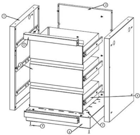
| # Part # Description IM-3DC | ||
| 1 No | 10-0678-CN side panel / panneau avant x | |
| 2 No | 75-0224-CN1HR back panel / panneau arrière x | |
| 3 No | 25-0018-CN1HR top/bottom rail / support superior/inférieur x | |
| 4 No | 70-0130 leveling foot / mise à niveau du pied x | |
| 5 No | 10-0575-CN1HR assembly, bottom shelf / ensemble de tablette inférieur x | |
| 6 No | 10-0677-CN drawer assembly / assemblage du tiroir x | |
| 7 No | 70-0086 #14 x 1/2" screw / vis #14 x 1/2" x | |
| 8 No | 10-0010 drawer slide / glosser, tiroir | x |
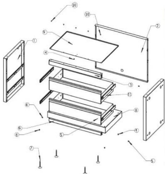
| # | Part # | Description | IM-2DC |
| 1 | N010-0678-CN | side panel / panneau avant | x |
| 2 | N475-0224-CN1HR | back panel / panneau arrêté | x |
| 3 | N525-0018-CN1HR | top/bottom rail / support superior/inférieur | x |
| 4 | N570-0086 | #14 x 1/2" screw / vis #14 x 1/2" | x |
| 5 | N010-0574 | false drawer front / avant faux de tiroir | x |
| 6 | N570-0008 | #8 x 1/2" screw / vis #8 x 1/2" | x |
| 7 N0 | 10-0677-CN | drawer assembly / assemblage du tiroir | x |
| 8 | N010-0575-CN1HR | bottom shelf assembly / ensemble de tablette inférieur | x |
| 9 N5 | 70-0130 | leveling foot / mise à niveau du pied | x |
| 10 | N610-0010 | drawer slide / glisser tiroir | x |
| # | Part # | DescriptionIM-WDC | |
| 1 N0 | 10-0678-CN side panel / panneau avant x | ||
| 2 N4 | 75-0224-CN1HR back panel / panneau arrière x | ||
| 3 N5 | 25-0018-CN1HR top/bottom rail / support superior/inférieur x | ||
| 4 N5 | 70-0086 #14 x 1/2" screw / vis #14 x 1/2" x | ||
| 5 N5 | 55-0032 paper towel rod / tige pour essuie-tout x | ||
| 6 N4 | 85-0012 cotter pin / vis x | ||
| 7 N0 | 10-0576-CN1HR paper towel housing assembly / assemblage de la porte du compartiment à essuie-tout | x | |
| 8 N5 | 70-0008 #8 x 1/2" screw / vis #8 x 1/2" x | ||
| 9 N0 | 10-0578 paper towel door assembly / assemblage de compartiment pour essuie-tout x | ||
| 10 | N555-0031 pivot rod / tige-pivot x | ||
| 11 | N010-0679-CN drawer assembly, trash can / assemblage du tiroir, panier à déchets | x | |
| 12 | N570-0130 leveling foot / mise à niveau du pied | x | |
| 13 | N010-0575-CN1HR assembly, bottom shelf / ensemble de tablette inférieur | x | |
| 14 | N610-0010 drawer slide / glisser tiroir | x | |
| 15 | N080-0228-CN1HR paper towel hoursing bracket / support tiroir de serviette en papier | x | |
| 16 | N080-0230-CN1HR door stop bracket / support caie-porte | x | |
| 17 | N160-0018 paper towel bracket / support de serviette en papier x | ||
| N185-0004 waste bin / poubelle x |

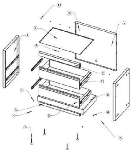
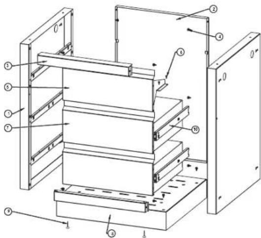
| # | 665 | 730 | Description | |
| 1 | N010-0678-CN | N010-0678-CN | side panel / panneau avant | x |
| 2 | N475-0392-CN1HR | N475-0233-CN1HR | back panel / panneau arrêté | x |
| 3 | N525-0020-CN1HR | N525-0021-CN1HR | top rail / support superior | x |
| 4 | N570-0086 | N570-0086 | #14 x 1/2" screw / vis #14 x 1/2" | x |
| 5 | N010-0682-CN | N010-0683-CN | drawer assembly / assemblage du tiroir | x |
| 6 | N525-0023-CN1HR | N525-0024-CN1HR | bottom rail / support inférieur | x |
| 7 | N570-0130 | N570-0130 | leveling foot / mise à niveau du pied | x |
| 8 | N010-0581-CN1HR | N010-0583-CN1HR | bottom shelf / tablette inférieur | x |
| 9 | N585-0051-CN1HR | N585-0052-CN1HR | drawer dripshield / écran anti-égouttement pour tiroir | x |
| 10 | N570-0013 | N570-0013 | #8 x 5/8" screw / vis #14 x 5/8" | x |
| 11 | N610-0010 | N610-0010 | drawer slide / glisser tiroir | x |
| N105-0012 | N105-0012 | 1.5" bushing / bagues de porte 1.5" | x | |
| N485-0007 | N485-0007 | black plug / bouchon noir | x |
| # | Part # | Description | 825 |
| 1 | N010-0678-CN | side panel left / panneau avant gauche | x |
| 2 | N570-0086 | screw, #14 x 1/2" / vis #14 x 1/2" | x |
| 3 | N010-0677-CN | drawer assembly / assemblage du tiroir | x |
| 4 | N570-0130 | leveling foot / mise à niveau du pied | x |
| 5 | N570-0013 | screw, #8 X 5/8" / vis #8 X 5/8" | x |
| 6 | N475-0260-CN1HR | divider / diviseur | x |
| 7 | N475-0393-CN1HR | back panel / panneau arrêté | x |
| 8 | N010-0839-CN1HR | bottom shelf / tablette inférieur | x |
| 9 | N475-0394 front fascia / fascia avant | x | |
| 10 | N585-0099-CN1HR | drawer drippshield / écran anti-égouttement pour tiroir | x |
| 11 | N525-0061-CN1HR | top rail / support superior | x |
| 12 | N525-0052-CN1HR | bottom rail / support inférieur | x |
| 13 N6 | 10-0010 drawer slide / glisser tiroir | x | |
| N105-0012 1.5" bushing / bagues de porte 1.5" | x |
| # | 245/300 485-1 500 Description | ||||
| 1 N0 | N010-0678-CN N010-0678CN | N N010-0678-CN side panel left / panneau avant gauche x | |||
| 2 N4 | 75-0224-CN1HR N475-0302 | 02-CN1HR N475-0302-CN1HR back panel / panneau arrêtére x | |||
| 3 N5 | 25-0031-CN1HR NS25-0042 | 42-CN1HR NS25-0041-CN1HR top rail / support superior x | |||
| 4 | N570-0086 | N570-0086 | N570-0086 | #14 x 1/2" screw / vis #14 x 1/2" | x |
| 5 | N010-0677CN | N010-0745-CN | N010-0745-CN | drawer assembly / assemblage du tiroir | x |
| 6 | N525-0018-CN1HR | N525-0040-CN1HR | N525-0040-CN1HR | bottom rail / support inférieur | x |
| 7 | N570-0130 | N570-0130 | N570-0130 | leveling foot / mise à niveau du pied | x |
| 8 | N010-0575-CN1HR | N010-0744-CN1HR | N010-0744-CN1HR | bottom shelf / tablette inférieur | x |
| 9 | N585-0062-CN1HR | N585-0085-CN1HR | N585-0084-CN1HR | drawer dripshield / écran anti-égouttement pour tiroir | x |
| 10 | N570-0013 | N570-0013 | N570-0013 | #8 x 1/2" screw / vis #8 x 1/2" | x |
| N610-0010 | N610-0010 | N610-0010 | slide, drawer / glisser, tiroir | x | |
| N485-0007 | N485-0007 | N485-0007 | black plug / bouchon noir | x | |
| N105-0012 | N105-0012 | N105-0012 | 1.5" bushing / bagues de porte 1.5" | x | |
| N710-0066 | dripan, replaces pan included with BI300 / tiroir d'égouttement, remplace le tiroir inclus avec le BI300 | x | |||
| # Part # Description BIB18 | |||
| 1 N0 | L0-1416-CN side panel / panneau avant x | ||
| 2 N4 | 75-0549-CN1HR back panel / panneau arrière x | ||
| 3 N0 | L0-0677-CN drawer assembl y / assemblage du tiroir x | ||
| 4 N6 | L0-0010 drawer slide / gisser tiroir x | ||
| 5 N5 | 25-0018-CN1HR top/botom rail/ support superior/inférieur x | ||
| 6 N5 | 25-0070-CN1HR top rail / support superior x | ||
| 7 N5 | 25-0166-CN1HR drawer shield / bouclier de tiroir x | ||
| 8 N0 | L0-0575-CN1HR bottom shelf / tablette inférieur x | ||
| 9 N5 | 70-0130 leveling foot / mise à niveau du pied x | ||
| 10 | N570-0013 | screw, #8 X 5/8" / vis #8 X 5/8" | x |
| 11 | N570-0086 | screw, #14 x 1/2" / vis #14 x 1/2" | x |
| N105-0012 1.5" bushirg / bagues de porte 1.5" x | |||

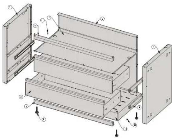
| # | Part # | Description | BIG32 | BIG38 | BIG44 |
| 1 | N010-1416-CN | side panel / panneau avant | x | x | x |
| 2 | N475-0550-CN1HR | back panel / panneau arrière | x | ||
| N475-0551-CN1HR | back panel / panneau arrière | x | |||
| N475-0553-CN1HR | back panel / panneau arrière | x | |||
| 3 | N010-0745-CN | drawer assembly / assemblage du tiroir | x | ||
| N010-1412-CN1HR | drawer assembly / assemblage du tiroir | x | |||
| N010-1414-CN1HR | drawer assembly / assemblage du tiroir | x | |||
| 4 | N610-0010 | drawer slide / glisser tiroir | x | x | x |
| 5 | N525-0040-CN1HR | bottom rail / support inférieur | x | ||
| N525-0073-CN1HR | bottom rail / support inférieur | x | |||
| N525-0075-CN1HR | bottom rail / support inférieur | x | |||
| 6 | N525-0071-CN1HR | top rail / support superior | x | ||
| N525-0072-CN1HR | top rail / support superior | x | |||
| N525-0074-CN1HR | top rail / support superior | x | |||
| 7 | N585-0167-CN1HR | drawer shield / bouclier de tiroir | x | ||
| N585-0164-CN1HR | drawer shield / bouclier de tiroir x | ||||
| N585-0165-CN1HR | drawer shield / bouclier de tiroir | x | |||
| 8 | N010-0744-CN1HR | bottom shelf / tablette inférieur | x | ||
| N010-1411-CN1HR | bottom shelf / tablette inférieur x | ||||
| N010-1413-CN1HR | bottom shelf / tablette inférieur | x | |||
| 9 | N570-0130 | leveling foot / mise à niveau du pied | x | x | x |
| 10 | N570-0013 | screw, #8 X 5/8" / vis #8 X 5/8" | x | x | x |
| 11 | N570-0086 | screw , #14 x 1/2" / vis #14 x 1/2" | x | x | x |
| N105-0012 | 1.5" bushing / bagues de porte 1.5" | x | x | x |

30












32

Napoleon products are protected by one or more U.S. and Canadian and/or foreign patents or patents pending.

- MODULAR CABINET ASSEMBLY INSTRUCTIONS
- RETAIN THIS MANUAL FOR FUTURE REFERENCE.
- EN
- Napoleon President's 10 Year Limited Warranty
- PLANNING YOUR NAPOLEON MODULAR OUTDOOR ISLAND
- TOOLS REQUIRED FOR ASSEMBLY (tools not included)
- GAS AND ELECTRICAL PIPING
- IM-UTC
- PROPANE SUPPLY HOSE ROUTING
- CABINET TO CABINET ASSEMBLY
- IM-FMP/FEP
- FRIDGE PANEL ATTACHMENT
- IM-45T CABINET 45 DEGREE CONNECTION
- IM-45T X 2 CABINET 90 DEGREE CONNECTION
- CABINET END PANEL KIT
- IM-CEP / IM-WSF CABINET END PANEL KIT
- CABINET LEVELING PROCEDURE
- DOOR REVERSAL
- Notes
- KEEP YOUR RECEIPT AS PROOF OF PURCHASE TO VALIDATE YOUR WARRANTY.
- Ordering Replacement Parts
- Warranty Information
- (Record information here for easy reference)
- INSTRUCTIONS D'ASSEMBLAGE DES CABINETS MODULAIRES
- PLANIFICATION DE VOTRE ÎLOT MODULAIRE EXTÉRIEUR NAPOLÉON
- INSTALLATION DE L'ALIMENTATION ÉLECTRIQUE ET DE LA TUYAUTERIE POUR LE GAZ
- IM-FMP/FEP PANNEAU D'ATTCHE DE REFRIGERATEUR
- IM-45T RACCORDEMENT DE CABINETS À 45 DEGRÉS
- IM-45T X 2 RACCORDEMENT DE CABINETS À 90 DEGRÉS
- IM-CEP ENSEMBLE DE PANNEAU D'EXTRÉMITÉ
- IM-CEP / IM-WSF ENSEMBLE DE PANNEAU D'EXTRÉMITÉ
- MISE DE NIVEAU DU CABINET
- PORTE INVERSE
- GARDEZ VOTRE REÇU COMME PREUVE D'ACHAT POUR VALIDER VOTRE
Brand : Napoleon
Model : IM-UGC665
Category : Grill