
Caldaia PK30 - Oven La Nordica - Free user manual and instructions
Find the device manual for free Caldaia PK30 La Nordica in PDF.


User questions about Caldaia PK30 La Nordica
0 question about this device. Answer the ones you know or ask your own.
Ask a new question about this device
Download the instructions for your Oven in PDF format for free! Find your manual Caldaia PK30 - La Nordica and take your electronic device back in hand. On this page are published all the documents necessary for the use of your device. Caldaia PK30 by La Nordica.
USER MANUAL Caldaia PK30 La Nordica
natural_image
Abstract geometric shape with a white square cutout, no text or symbols presentATTENTION


SURFACES CAN BECOME VERY HOT! ALWAYS USE PROTECTIVE GLOVES!
During combustion, thermal energy is released that significantly increases the heat of surfaces, doors, handles, controls, glass, exhaust pipes, and even the front of the appliance. Avoid contact with those elements if not wearing protective clothing (protective gloves included). Make sure children are aware of the danger and keep them away from the stove during operation.
ENGLISH 4
CHARACTERISTICS......4
INTRODUCTION 5
WARNINGS....7
SAfETy 7
ROUTINE MAINTENANCE 9
INSTALLATION....10
PREPARATIONS FOR MAINTENANCE....10
HyDRAULIC SySTEM....12
INSTALLATION AND SAFETY dEvICES....12
ANTI-CONDENSATION DEVICE (MANDATORY) 13
IdentIFICATION OF PR COMPONENTS 14
IdENTIFICATION OF Pk COMPONENTS....15
BULB THERMOSTAT REACTIVATION 16
fFEATURES....16
PELLETS AND LOADING 17
GENERAL WARNINGS....20
FIRST IGNITION SETTINGS....21
dATE-TIME....21
IANGuAGE....21
dEGREES 21
STAND-By - ADDITIONAL THERMOSTAT 23
AdditionAI thermostAt functioning with STANd-By Active....23
AddITIONALThERMOSTAT OPERATION with STAND-By dEACTIvATED 23
AddITIONAL Thermostat Installation....23
CHRONO....24
ENABIING/dISABIING The ChRONO 24
SETTINGS 26
dISPIAy 26
STAND - By 26
FIRST IOAd 26
OutLET AIR....26
CIEANING The COMBuSTION ChAMBER 27
wi-Fi....27
RESET....27
AUX....27
OPTIONAL ADDITIONAL BOARD (STANDARD ON PR20 AND PR30) 27
CLEANING AND MAINTENANCE....28
MAINTENANCE....28
PERIODIC CLEANING uNdER uSER'S RESPONSIBILITY....28
CLEANING AND MAINTENANCE SUMMARY TABLE 31
uSER CLEANING....31
QuAllFIEd TEChNICIAN....31
ROUTINE MAINTENANCE PERFORMED By qQUALIFIED TECHNICIANS 31
ShuT-dOwN (ENd OF SEASON)....31
DISPLAYS 33
ALARMS 33
GUARANTEE TERMS 35
DISPOSAL....36
| CHARACTERISTICS | PK15 PK20 PK30 | |||
| - PR20 PR30 | ||||
| Weight kg 295 295(PK)/310(PR) 310(PK)/325(PR) | ||||
| Height mm 1398 1398 1398 | ||||
| Width mm 822 822 892 | ||||
| Depth mm 745 745 (PK)/817PR) | 745 (PK)/817PR | |||
| Diameter of fume outlet pipe | mm 100 100 120 | |||
| Diameter of fume intake pipe | mm | 60 | 60 | 60 |
| Min global thermal input | kW 4,7 | 6,5 | 9,6 | |
| Min useful thermal input | kW 4,1 | 5,7 | 8,9 | |
| Max global thermal input | kW | 16,2 | 21,7 | 32,5 |
| Max useful thermal input (to water) | kW | 15 | 20 | 30 |
| Min fuel consumption per hour | kg/h | 1,0 | 1,4 | 2,0 |
| Max fuel consumption per hour | kg/h | 3,4 | 4,6 | 6,8 |
| Pellet hopper capacity | kg/L | 75/ 121 | 75/ 121 | 75/ 121 |
| Recommended flue draught | Pa | 3 ÷ 5 3 ÷ 5 3 ÷ 5 | ||
| mbar | 0,03 ÷ 0,05 | 0,03 ÷ 0,05 | 0,03 ÷ 0,05 | |
| Rated electrical power | W | 410 410 410 | ||
| Reduced power electrical consumption | W | 60 | 60 | 70 |
| Rated power electrical consumption | W | 65 | 65 | 85 |
| Power in stand-by | W | 3 | 3 | 3 |
| Rated tension | Vac | 230 230 230 | ||
| Rated frequency | Hz | 50 | 50 | 50 |
| Diameter of water input/output pipe | “ | 1 | 1 | 1 |
| Diameter of automatic exhaust pipe | “ | 1/2 | 1/2 | 1/2 |
| Pump head | m | 6 | 6 | 6 |
| Maximum water operating pressure allowed | bar | 3 | 3 | 3 |
| Minimum water operating pressure allowed | bar | 0.6 | 0.6 | 0.6 |
| Reduced power fume temperature | °C | 63,6 | 62 | 66,5 |
| Rated power fume temperature | °C | 99,8 | 106,6 | 113,8 |
| Reduced power fume flow rate | g/s | 5,1 | 5,8 | 9,1 |
| Rated power fume flow rate | g/s | 8,5 | 10,4 | 15,9 |
| Boiler class | 5 | 5 | 5 | |
| Combustion period | h | 22 | 16 | 11 |
| Water thermostat adjustment field | °C | 65/80 | 65/80 | 65/80 |
| Minimum water return temperature | °C | 55 | 55 | 55 |
| Direct efficiency at rated power | % | 93,0 | 92,4 | 92,4 |
| Condensing unit | NO | NO | NO | |
| Dimensions of the feeding door | mm | 306X400 | 306X400 | 306X400 |
* Value measured in anechoic chamber with the unit running at rated power.
| WATER FLOW(kg/h) | WATER SIDERESISTANCE(mbar) | |||
| PK15 | Temperature jump corresponding | T = 10K 1 | 300 60 | |
| T = 20K 6 | 50 15 | |||
| PK20 | Temperature jump corresponding | T = 10K 1 | 730 106 | |
| PR20 | T = 20K 8 | 65 26 | ||
| PK30 | Temperature jump corresponding | T = 10K 2 | 601 1687 | |
| PR30 | T = 20K 1 | 301 422 | ||
INTRODUCTION
The boilers produced in our factory are built with attention to the individual components so as to protect both the user and the installer from any accidents. It is therefore recommended that after any intervention on the product, the authorised staff pay particular attention to the electric connections, especially the stripped parts of the wires. These must not escape from the terminal board in any situation, thus preventing possible contact with the live parts of the wire.
The instruction manual is an integral part of the product: make sure that it always accompanies the appliance, even if transferred to other owners or user or is transferred to another place. If it is damaged or lost, request another copy from the area technician.
This generator must be intended for the use it has been specifically made for. The manufacturer is exempted from any liability, contractual and extracontractual, for injury/damage caused to persons/animals and objects, due to installation, adjustment and maintenance errors and improper use.
INSTALLATION
Installation of the generator and auxiliary equipment in relation to the heating system must comply with all current Standards and Regulations and to those envisioned by the law. Installation must be carried out by authorised staff, who must provide the buyer with a declaration of conformity for the system and will assume full responsibility for final installation and as a consequence the correct functioning of the installed product.
It is necessary to bear in mind all laws and national, regional, provincial and town council Standards present in the country the appliance has been installed.
The Manufacturer cannot be held responsible for the failure to comply with such precautions. It is recommended to wash all the pipes of the system well before installation to remove any residue that could compromise the correct operation of the appliance. During installation, inform the user regarding:
a. If water leaks, he must close the water supply and promptly inform the after-sales technical service.
b. The system working pressure must be checked periodically. If the generator is not used for a long period of time, it is recommended to contact the after-sales technical service to carry out at least the following operations:
- Set the master switch to position 0.
- Close the water taps of both the heating system and the domestic hot water system.
- Empty the heating system and the domestic hot water system if there is risk of freezing.
COMMISSIONING
After removing the packaging, ensure that the content is intact and complete.
Otherwise, contact the dealer where the appliance was purchased.
When commissioning the product, verify that all safety and control devices the generator consists of work properly. All electrical components that make up the generator must be replaced with original spare parts exclusively by an authorised technical assistance centre, thereby guaranteeing correct operation.
Before leaving the system, the staff in charge of commissioning must monitor the operation of the generator for at least one complete work cycle. The generator must be serviced at least once a year, programming it in advance with the technical assistance centre
STANDARDS
The boilers have been designed and realised in compliance with the following Directives:
♦ UNI EN 303-5 Boilers for central heating. Boilers for solid fuel, with manual and automatic feeding, with a nominal heat output of up to 500 kW
DIRECTIVES
2006/42/EC: directive MD
RED (2014/53/EU)
◆ 2011/65/EU: directive RoHS 2
FOR SAFETY
It is forbidden for the generator to be used by children or unassisted disabled persons.
Do not touch the generator when you are barefoot or when parts of the body are wet or humid.
The safety and adjustment devices must not be modified without the authorisation or indications of the manufacturer.
Do not pull, disconnect, twist electric cables leaving the generator, even if disconnected from the electric power supply mains.
Do not close or reduce the dimensions of the airing vents in the place of installation.
- The airing vents are indispensable for correct combustion.
Do not leave the packaging elements within reach of children or unassisted disabled persons.
- The hearth door must always be closed during normal functioning of the product.
- Avoid direct contact with parts of the appliance that tend to heat up during functioning.
- Check for the presence of any obstructions before switching the appliance on following a prolonged standstill period.
The generator has been designed to function in any climatic condition. In particularly adverse conditions (strong wind, freezing) safety systems may intervene to switch the generator off.
If this occurs, contact the technical after-sales service and always disable the safety system.
If the flue should catch fire, be equipped with suitable systems for suffocating the flames or request help from the fire service.
If the generator should block, indicated by a signal on the display and that is not relative to lack of routine maintenance, contact the technical after-sales centre.

THESE BOILERS MUST BE USED TO HEAT WATER TO A TEMPERATURE THAT DOES NOT EXCEED BOILING POINT IN THE CONDITIONS OF INSTALLATION.
We thank you for having chosen our company; our product is a great heating solution developed from the most advanced technology with top quality machining and modern design, aimed at making you enjoy the fantastic sensation that the heat of a flame gives, in complete safety.
Warnings
This instructions manual is an integral part of the product: make sure that it always accompanies the appliance, even if transferred to another owner or user, or if transferred to another place. If it is damaged or lost, request another copy from the area technician. This product is intended for the use for which it has been expressly designed. The manufacturer is exempt from any liability, contractual and extracontractual, for injury/damage caused to persons/animals and objects, due to installation, adjustment and maintenance errors and improper use.
Installation must be performed by qualified staff, which assumes complete responsibility for the definitive installation and consequent good functioning of the product installed. One must also bear in mind all laws and national, regional, provincial and town council Standards present in the country in which the appliance has been installed, as well as the instructions contained in this manual.
The Manufacturer cannot be held responsible for the failure to comply with such precautions.
After removing the packaging, ensure that the content is intact and complete. Otherwise, contact the dealer where the appliance was purchased.
All electric components that make up the product must be replaced with original spare parts exclusively by an authorised after-sales centre, thus guaranteeing correct functioning.
safety
- THE APPLIANCE MAY BE USED BY CHILDREN 8 YEARS OF AGE OR OLDER AND INDIVIDUALS WITH REDUCED PHYSICAL, SENSORY, OR MENTAL CAPACITIES OR WITHOUT EXPERIENCE OR THE NECESSARY KNOWLEDGE, PROVIDED THAT THEY ARE SUPERVISED OR HAVE RECEIVED INSTRUCTIONS ON SAFE USE OF THE APPLIANCE AND THAT THEY UNDERSTAND THE INHERENT DANGERS.
- THE GENERATOR MUST NOT BE USED BY PERSONS (INCLUDING
CHILDREN) WITH REDUCED PHYSICAL, SENSORY AND MENTAL CAPACITIES OR WHO ARE UNSKILLED PERSONS, UNLESS THEY ARE SUPERVISED AND TRAINED REGARDING USE OF THE APPLIANCE BY A PERSON RESPONSIBLE FOR THEIR SAFETY.
- THE CLEANING AND MAINTENANCE REQUIRED BY THE USER MUST NOT BE PERFORMED BY CHILDREN WITHOUT SUPERVISION.
CHILDREN MUST BE CHECKED TO ENSURE THAT THEY DO NOT PLAY WITH THE APPLIANCE. - DO NOT TOUCH THE GENERATOR WHEN YOU ARE BAREFOOT OR WHEN PARTS OF THE BODY ARE WET OR DAMP.
- THE SAFETY AND ADJUSTMENT DEVICES MUST NOT BE MODIFIED WITHOUT THE AUTHORISATION OR INDICATIONS OF THE MANUFACTURER.
- DO NOT PULL, REMOVE, TWIST THE ELECTRICAL CABLES COMING OUT OF THE PRODUCT EVEN IF IT IS DISCONNECTED FROM THE MAINS. - IT IS ADVISED TO POSITION THE POWER SUPPLY CABLE SO THAT IT DOES NOT COME INTO CONTACT WITH HOT PARTS OF THE APPLIANCE.
- THE POWER SUPPLY PLUG MUST BE ACCESSIBLE AFTER INSTALLATION.
- DO NOT CLOSE OR REDUCE THE DIMENSIONS OF THE AIRING VENTS IN THE PLACE OF INSTALLATION. THE AIRING VENTS ARE ESSENTIAL FOR CORRECT COMBUSTION.
- DO NOT LEAVE THE PACKAGING ELEMENTS WITHIN REACH OF CHILDREN OR UNASSISTED DISABLED PERSONS.
- THE HEARTH DOOR MUST ALWAYS BE CLOSED DURING NORMAL FUNCTIONING OF THE PRODUCT.
- WHEN THE APPLIANCE IS FUNCTIONING AND HOT TO THE TOUCH, ESPECIALLY ALL EXTERNAL SURFACES, ATTENTION MUST BE PAID
- CHECK FOR THE PRESENCE OF ANY OBSTRUCTIONS BEFORE SWITCHING THE APPLIANCE ON FOLLOWING A PROLONGED PERIOD OF INACTIVITY.
- THE GENERATOR HAS BEEN DESIGNED TO FUNCTION IN ANY CLIMATIC CONDITION. IN PARTICULARLY ADVERSE CONDITIONS (STRONG WIND, FREEzING) SAFETY SYSTEMS MAY INTERVENE THAT SWITCH THE GENERATOR OFF. IF THIS OCCURS, CONTACT THE TECHNICAL AFTER-SALES SERVICE AND ALWAYS DISABLE THE SAFETY
SYSTEMS.
IN THE EVENT THE FLUE CATCHES FIRE, USE SUITABLE SYSTEMS FOR SUFFOCATING THE FLAMES OR REQUEST HELP FROM THE FIRE BRIGADE.
- THIS APPLIANCE MUST NOT BE USED TO BURN WASTE
- DO NOT USE ANY FLAMMABLE LIQUIDS FOR IGNITION
◆ DURING THE FILLING PHASE DO NOT PUT THE BAG OF PELLETS TO INTO CONTACT WITH THE PRODUCT
- THE MAJOLICAS ARE TOP QUALITY ARTISAN PRODUCTS AND AS SUCH CAN HAVE MICRO-DOTS, CRACKLES AND CHROMATIC IMPERFECTIONS. THESE FEATURES HIGHLIGHT THEIR VALUABLE NATURE. DUE TO THEIR DIFFERENT DILATION COEFFICIENT, THEY PRODUCE CRACKLING, WHICH DEMONSTRATE THEIR EFFECTIVE AUTHENTICITY. TO CLEAN THE MAJOLICAS, IT IS RECOMMENDED TO USE A SOFT, DRY CLOTH. IF A DETERGENT OR LIQUID IS USED, THE LATTER COULD PENETRATE INSIDE THE CRACKLES, HIGHLIGHTING THEM.
- SINCE THE PRODUCT CAN TURN ON AUTOMATICALLY THANKS TO THE TIMER, OR REMOTELY USING THE DEDICATED APPLICATIONS, IT IS STRICTLY FORBIDDEN TO LEAVE ANY COMBUSTIBLE OBJECT WITHIN THE SAFETY DISTANCES INDICATED ON THE TECHNICAL DATA PLATE.
- INTERNAL COMBUSTION CHAMBER PARTS CAN BE SUBJECT TO EXTETICAL WARN, IT DOESN'T AFFECT THE FUNCTIONALITY
routine Maintenance
Based on Decree 22 January 2008 n°37 art.2, routine maintenance means interventions aimed at reducing degradation due to normal use, as well as dealing with accidental events entailing the need of first interventions, which however do not modify the structure of the system upon which one is intervening or its intended use according to the requirements laid down by the technical standards in force and by the manufacturer's use and maintenance manual.
INSTALLATION
GENERAL
The flue gas exhaust and hydraulic connections must be carried out by qualified personnel who must issue installation conformity documentation compliant with national standards.
The installer must provide the owner or person acting for him, according to the legislation in force, with the declaration of conformity, supplied with:
1) the use and maintenance manual of the appliance and of the system components (such as for example, the smoke ducts, chimney, etc.);
2) photocopy or photograph of the chimney plaque;
3) system booklet (where applicable).
The installer must ask to be issued with a receipt stating that the documentation has been provided, and must keep it with a copy of the technical documentation relating to the installation.
For installation in a condominium, prior approval from the condominium's administrator must be requested.
Where required, check the exhaust gas emissions after installation. Should a sampling point be installed, it must be airtight.
COMPATIBILITY
Do not install in rooms with a fire hazard. It is also forbidden to install it in living areas with the following characteristics:
- where there are liquid fuel appliances with continuous or discontinuous operation that draw the combustion air into the room in which they are installed.
- where there are type B gas appliances intended for heating, with or without domestic hot water production and in adjacent and communicating rooms.
- where the depression measured in situ between the external and internal environment is greater than 4 Pa.
N.B.: Watertight appliances can also be installed in the cases indicated in points 1, 2 and 3 of this paragraph.
INSTALLATIONS IN BATHROOMS, BEDROOMS AND STUDIO FLATS
Installation in bathrooms, bedrooms and studio flats is only allowed for sealed or closed hearth appliances with ducted combustion air taken from the outside.
POSITIONING AND SAFETY DISTANCES
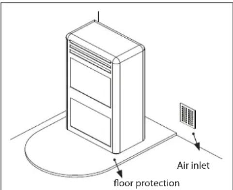
The support surfaces and/or points must have a suitable capacity to bear the overall weight of the appliance, accessories and coverings. If the floor is made of a combustible material, we recommend using a non-combustible material to protect the front part from any burnt material which might fall during routine cleaning operations. The generator must be level to function properly. The side walls, the rear walls and the floor support surface should be made of non-combustible material.
MINIMUM DISTANCES (PELLET STOVES)
Installation next to flammable or heat-sensitive materials is permitted only if the special safety distances specified on the label at the beginning of the manual (pag.2) are observed. If the materials are not flammable, you must keep a side and rear distance of at least 100 mm (without the inserts). For products equipped with rear spacers, wall-mounting installation is permitted exclusively for the rear side.
PREPARATIONS FOR MAINTENANCE
text_image
Air inlet floor protectionOne must also bear in mind all laws and national, regional, provincial and town council regulations in force in the country in which the appliance has been installed, as well as the instructions contained in this manual.
To carry out extraordinary maintenance operations on the product, it may be necessary to move it away from the adjacent walls. This must be done by a technician authorised to disconnect the combustion product evacuation ducts and then reconnect them. For heaters connected to the hydraulic system, the connection between the system itself and the product must be made in such a way that, when an authorised technician is about to carry out extraordinary maintenance operations, it is possible to move the heater at least 1 metre away from the adjacent walls.
INSTALLING INSERTS
When installing inserts, access must be prevented to the internal parts of the appliance and it must not be possible to access live parts during extraction operations.
Any wiring, for example the power cable or room probe, must be positioned so as not to be damaged during movement of the insert and must not come into contact with hot parts. If a cavity made of combustible material is installed, we recommend taking all the safety precautions indicated by the installation standards.
VENTILATION AND AERATION OF INSTALLATION ROOMS
In case of non-airtight heater and/or installation, the ventilation must respect the minimum area indicated below (considering the highest value among those provided):
| Appliance categories Reference standard | Percentage of the net opening section with respect to the appliance fumes outlet section | Minimum net opening value of the ventilation duct |
| Pellet stoves UNI EN 14785 - 80 cm ^2 | ||
| Boilers UNI EN 303-5 50% 100 cm ^2 |
Under any condition, including in the presence of extractor hoods and/or of controlled forced ventilation systems, the pressure difference between the generator installation rooms and the outside must always be equal to or less than 4 Pa.
Extraflame®
In the presence of type B gas appliances with intermittent operation not intended for heating, they must have their own aeration and/or ventilation opening.
The air inlets must meet the following requirements:
◆ they must be protected with grids, metal mesh, etc., but without reducing the net useful section;
◆ they must be made so as to make the maintenance operations possible;
- positioned so that they cannot be obstructed;
The clean and non-contaminated air flow can also be obtained from a room adjacent to that of installation (indirect aeration and ventilation), as long as the flow takes place freely through permanent openings communicating with the outside.
The adjacent room cannot be used as a garage, or to store combustible material or for any other activity with a fire hazard, bathroom, bedroom or common room of the building.
Flue gas eXhaust
The heat generator works in depression and is equipped with an outlet fan for flue gas extraction. There must be a single exhaust system for the generator. Using a flue that is shared with other devices is not allowed.
The components of the flue gas exhaust system must be chosen in relation to the type of appliance to be installed in compliance with:
- UNI/TS 11278 in the event of metal chimneys, with particular attention to that stated in the specification;
♦ UNI EN 13063-1 and UNI EN 13063-2, UNI EN 1457, UNI EN 1806 in the event of non-metallic chimneys.
The length of the horizontal section must be minimal and, in any case, no longer than 3 metres, with a minimum upward slope of 3%
There must not be more than 4 direction changes including the one due to the use of the "T" element.
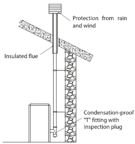
A "T" fitting with a condensation collection cap must be provided at the base of the vertical section.
If the exhaust is not inserted in an existing flue, a vertical section with a windproof end piece is required (UNI 10683).
The vertical duct can be inside or outside the building. If the smoke duct is inserted in an existing flue, it must be certified for solid fuel. - If the smoke duct is outside the building, it must always be insulated.
- The smoke ducts must have at least one airtight inlet for flue gas sampling.
- All the sections of the flue gas duct must be accessible to inspection.
- Inspection openings must be provided for cleaning.
If the generator has a fume temperature lower than 160^ C+ ambient temperature caused by the high yield (contact technicians) it MUST be resistant to humidity.
A flue system that does not respect the previous points or, in general, that does not comply with the regulations, may cause condensation phenomena inside it.
ChIMneY CaP
The chimney caps must meet the following requirements:
◆ they must have a useful outlet section no less than double that of the chimney/ducted system on which it is installed;
◆ they must be adapted in order to prevent the penetration of rain and snow in the chimney/ducted system;
◆ they must be built so that, in the event of winds coming from all directions and from any angle, the expulsion of combustion products is in any case ensured;
ExAMPIEs of coRREcT connEcTion To ThE chiMnEy
text_image
Protection from rain and wind Insulated flue Condensation-proof "T" fitting with inspection plug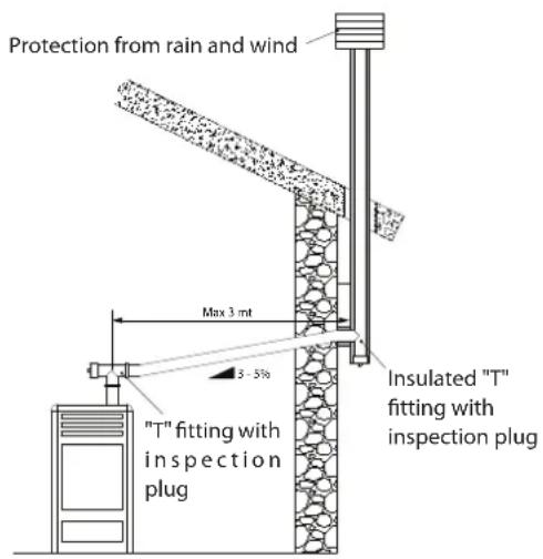
text_image
Protection from rain and wind Max 3 mt Insulated "T" fitting with inspection plug "T" fitting with inspection plugCOnneCtlOn tO the Mains eleCtrlC suPPIY
The generator is supplied with an electric power cable to be plugged into a 230V 50 Hz socket, possibly with a circuit breaker switch. The socket must be easily accessible.
The electrical system must be compliant with standards. The efficiency of the earthing circuit must be checked. Unsuitable earthing of the system can cause malfunctioning for which the manufacturer will not be held liable.
Power supply variations beyond 10% can cause faulty operation of the product.
HYDRAULIC SYSTEM
Certain concepts referring to the Italian UNI 10412-2 Standard are described in this chapter.
As previously described, when installing, all national, regional, provincial and town council Standards in force provided by the country in which the appliance has been installed must be complied with.
When installing the generator, it is MANDATORY to adjust the system with a pressure gauge to display the water pressure.
| TABLE OF SAFETY DEVICES FOR CLOSED VESSEL SYSTEM AND NOT PRESENT IN THE PRODUCT | |
| Safety valve | √ |
| Pump control thermostat (it is managed by the water probe and the board program) | √ |
| Water temperature indicator (display) | √ |
| Pressure transducer with display | X |
| Automatic circuit breaker adjustment switch (managed by board program) | √ |
| Manometer | √ |
| Water overheating automatic circuit breaker switch (block thermostat) | √ |
| Circulation system (pump) | √ |
| Expansion system | √ |
| DSA thermal discharge coil | X |
| DSA valve (Automatic Safety Device) | X |
Pay attention to the correct sizing of the system:
◆ Generator power compared to the thermal requirement
- Possible need for a buffer tank
INSTALLATION AND SAFETY DEVICES
The installation, relative system connections, commissioning and inspection of correct functioning must be carried out perfectly, in full compliance with Standards in force, national, regional and municipal, as well as these instructions. For Italy, installation must be carried out by professionally qualified staff (Ministerial Decree dated 22.01.08 n°37).
Extraflame S.p.A. declines all responsibility for damage to objects and/or persons caused by the system.
TYPE OF SYSTEM
- There are 2 different types of system:
- Open vessel system and closed vessel system.
- The product has been designed and built to work with closed vessel systems.

CHECK THAT THE PRELOAD OF THE EXPANSION VESSEL IS SET TO 1.5 BAR.
SAFETY DEVICES FOR CLOSED VESSEL SYSTEM
According to the UNI 10412-2 Standard in force in Italy, closed systems must feature the following: safety valve, pump control thermostat, temperature indicator, pressure indicator, automatic temperature regulation device, automatic thermal cut-off switch (safety thermostat), pump system, expansion system.
DISTAnCES of SAFETY DEvICES ACCoRDIng To THE LEgISLATlon
The temperature safety sensors must be on the machine at a distance no greater than 30 cm from the flow connection. Whenever the generators lack a device, those missing can be installed on the generator flow pipe, within a distance no greater than 1 m from the machine.
CHECKS wHEn STARTing foR THE FIRST TIME
Before connecting the boiler:
a) Discharge the air from the system using the air vent in the boiler and activating the air discharge cycle from the display
b) wash all system piping thoroughly in order to remove any residues which might compromise the correct operation of certain system components (pumps, valves, etc.).
c) The company recommends installing a magnetic filter in the generator return, to increase the operational life of the boiler, make it easier to remove impurities and increase the overall efficiency of the system.
It is also advisable to perform an inspection using appropriate instruments, to check for any stray currents that may cause corrosion.
d) Check that the flue has adequate draft, is not narrowed and that other appliances do not discharge into the flue. This is to prevent unexpected power increases. Only after this check can the flue fitting be mounted between the boiler and the flue. It is advisable to check the fittings with pre-existing flues.
AnTI-ConDEnSATlon DEvICE (MAnDAToRY)
It is mandatory to create a suitable anti-condensation circuit, which guarantees a return temperature of the unit of at least 55^ C. The anti-condensation valve, for example, is used in solid fuel boilers as it prevents the return of cold water in the exchanger. A high return temperature improves efficiency, reduces the formation of condensation from the fumes and extends the service life of the generator. The manufacturer recommends using the 55^ C model with 1" hydraulic connections.
For products with PWM* pump control, installation is considered equivalent to the creation of a suitable anti-condensation circuit in cases where:
- the heat generator pump is the only one in the system, or
- between the heat generator and the system there is a plate heat exchanger, or
between the heat generator and the system there is a hydraulic compensator or an inertial storage device (buffer)
*Check the technical data sheet on the website.
Valve sold as an accessory (optional)
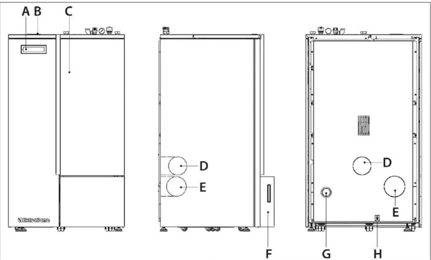
Identification of pr components
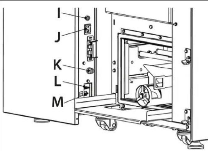
text_image
I J K L M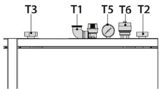
text_image
T3 T1 T5 T6 T2| a Display | K Bulb thermostat reactivation | ||
| B Pellet hopper lid L Serial input | |||
| c Door m TA inlet | |||
| d Combustion fumes exhaust pipe ∅100 (PR20) t1 3 bar safety drain | |||
| e Combustion fumes exhaust pipe ∅120 (PR30) t2 Boiler flow/output | |||
| f Ash extractor t3 Boiler return/input | |||
| G Air intake hose for combustion t5 Manometer | |||
| H Power outlet for electrical cable t6 Air vent | |||
| I | Fuse | ||
| J | ON/OFF | ||
Identification of pK components
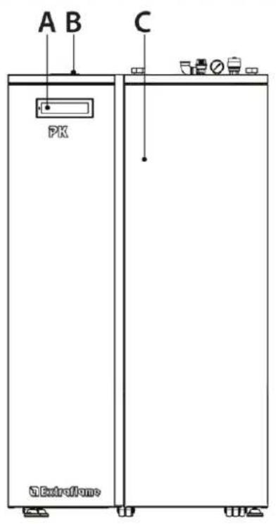
text_image
A B C PK External flares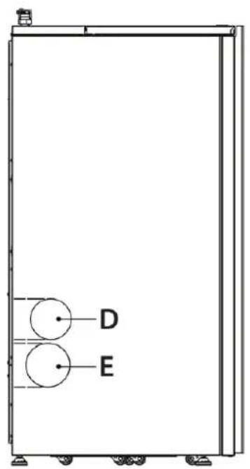
text_image
D E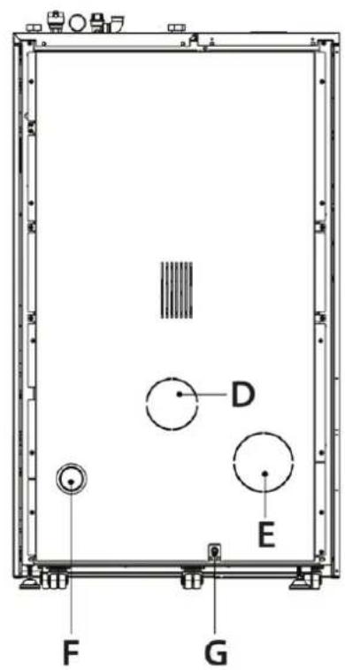
text_image
A D E F G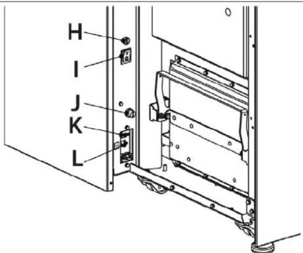
text_image
H I J K L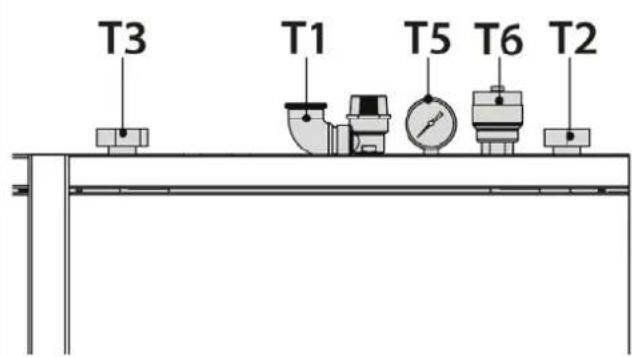
text_image
T3 T1 T5 T6 T2| a Display | J Bulb thermostat reactivation | ||
| B Pellet | hopper lid K Serial input | ||
| c Door L | TA inlet | ||
| d Combustion fumes exhaust pipe ∅100 (PK15-20) t1 3 bar safety drain | |||
| e Combustion fumes exhaust pipe ∅120 (PK30) t2 Boiler flow/output | |||
| f Air intake hose for combustion t3 Boiler return/input | |||
| G Power outlet for electrical cable t5 Manometer | |||
| H Fuse | t6 Air vent | ||
| I | ON/OFF | ||
BULB tHermostat reactivation
The figure below shows the reactivation position. It is recommended to contact the qualified technician if one of the rearms should be triggered, so as to verify the cause.
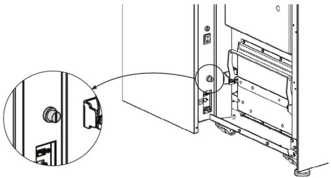
natural_image
Technical line drawing of a door panel assembly with a close-up inset showing internal components (no text or symbols)featUres
| PK 15 PK20 | PK 30 | ||
| PR20 PR30 | |||
| Water content of the thermo-product heat exchanger (I) | 46 46 63 | ||
| Volume of expansion vessel integrated into thermo-product (I) | 8 8 8 | ||
| 3 bar safety valve integrated into the thermo-product | √ √ | √ | |
| Pump integrated into the thermo-product | √ √ | √ | |
| Pump max. head (m) | 6 6 6 |
* Envision any intEgRativE ExPansion vEssEI on thE basis of thE systEm watER contEnt.
The diagram at the side illustrates the behaviour of the pump used on our thermo-products at the speeds that can be set.
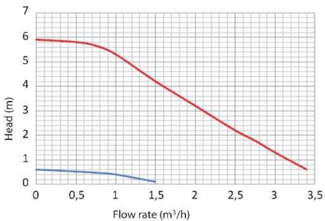
line
| Flow rate (m³/h) | Head (m) - Red Line | Head (m) - Blue Line | | ---------------- | ------------------- | -------------------- | | 0.0 | 6.0 | 0.5 | | 0.5 | 5.8 | 0.4 | | 1.0 | 5.2 | 0.3 | | 1.5 | 4.0 | 0.1 | | 2.0 | 3.0 | - | | 2.5 | 2.0 | - | | 3.0 | 1.0 | - | | 3.5 | 0.5 | - |
for correct Generator operation, tHe HydraULlc system pressUre mUst Be Between 0.6 and 3 Bar.
Pellets and loading
Pellets are made by subjecting wood shavings i.e. the rejects of pure unpainted wood from sawmills, carpentry products and products from other activities connected to wood working and transformation, to very high pressures.
This type of fuel is fully ecological as no glues are used for its compaction. In fact, pellet compactness is guaranteed over time by a natural substance found in wood: lignite.
In addition to being an ecological fuel, making best use of wood residue, pellets also have a series of technical advantages.
While wood has a calorific value of 4.4 kWh/kg (with 15% moisture, therefore after approximately 18 months of curing), that of pellets is 5 kWh/kg.
Pellet density is about 650 kg/m^3 and water content is equal to 8% of its weight. For this reason pellets do not need to be cured to obtain a sufficient heat yield.
The pellets used must comply with the characteristics described by the following standards:
en PIUs, Uni en 14961-2, (Uni en iso 17225-2), Class A1 and
Uni en 303-5 with the following characteristics: water content ≤ 12%, ash content ≤ 0.5% and lower calorific value >17 MJ/kg (in the case of boilers).
The manufacturer always recommended using pellets with a diameter of 6 mm with its products.
Pellet stoRage
In order to ensure problem-free combustion pellets must be stored in a dry place.
Open the tank lid and load the pellets using a scoop.
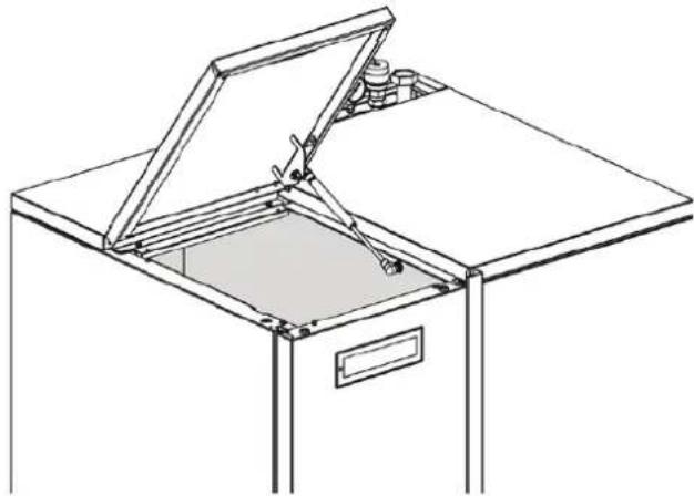
natural_image
Line drawing of an open cabinet with metal frame and door, no text or symbols present
tHe Use of eXPIRed Pellets or anY otHeR MaterRial Will aFFeCt tHe FUnCtionalitY of YoUR geneRatioR and MaY lead to tHe teRMination of f the WaRRantY and Cessation of anY aCCoMPanYing ResPonsiBilitY on tHe PaRt of f the ManUFaCtUReR
The stove is equipped with a modern touch screen display with Wi-Fi technology that allows for the individual functions of the unit to be adjusted by the user in an easy and intuitive manner.
Touch the buttons (icons) on the display to activate the actions. The touch screen display reacts with the touch of your fingers.
CAUTION!
- Do not use screen protectors: the display might not work properly
Do not place the touch screen display in direct or indirect contact with water. The touch screen display may not work properly in the presence of humidity or if it is exposed to water.
To avoid damaging the touch screen display, do not touch it with sharp objects and do not press it too hard with your fingers.
During opening and closure, press only on the outer frame of the Display.
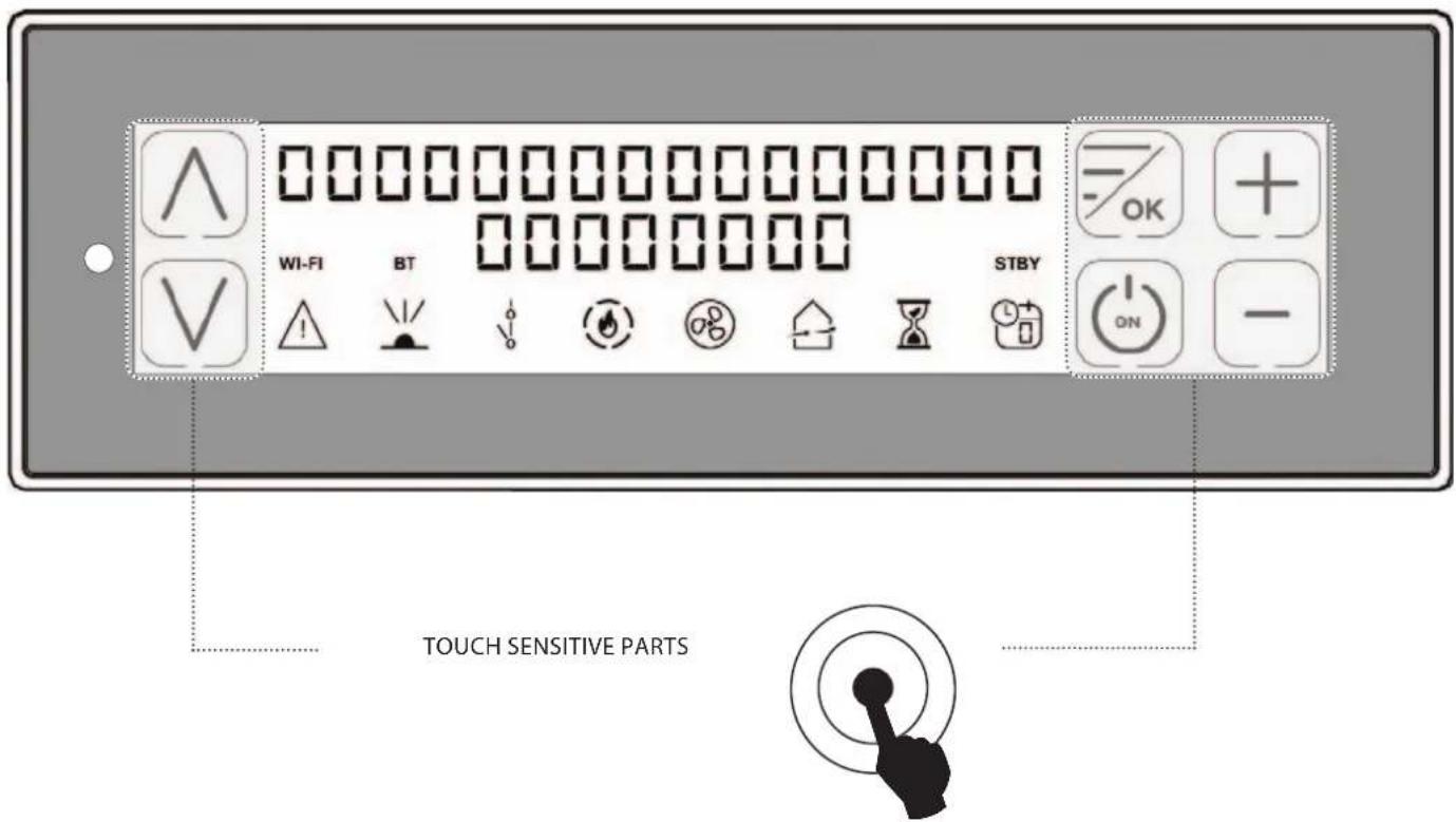
text_image
WI-FI BT STBY TOUCH SENSITIVE PARTS| FREQUENCY BANDS MAXIMUM POWER TRANSMITTED | |
| Wi-Fi 20.0 DBM | |
| BLUETOOTH Class-3 | |
CONTROL BOARD
text_image
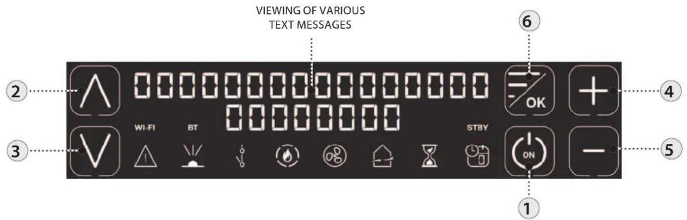
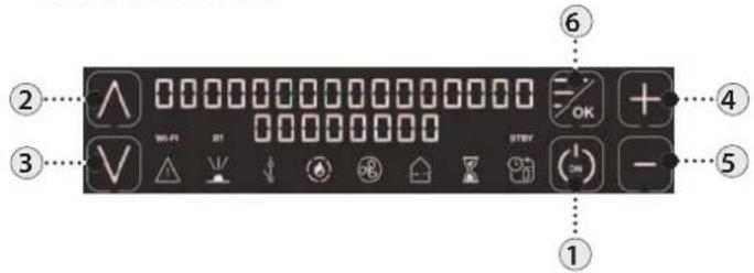
VIEWING OF VARIOUS TEXT MESSAGES ② 3 4 5 6 WI-FI BT STBY ON① On/off stove.
② Increase operating power / scroll through the menus.
3 Decrease operating power / scroll through the menus.
4 Increase operating set thermostat / scroll through the menus.
5 Decrease operating set thermostat / scroll through the menus.
6 To access the menu / confirm key.
| ICON KEY | |||
 | Indicates the presence of an alarm.Off: indicates there are no alarmsOn: indicates the presence of an alarm |  | Delayed switch-off icon.Off: deactivated.On: activated. |
 | Indicates the reception of the IR signalOn = IR command receivedOff = IR communication absent |  | Indicates the weekly programming statusOff: deactivated.On: activated.The number indicates the current reference time frame. |
 | Indicates contact of the external additional thermostatClosed contact: the contact of the external additional thermostat is closed.Open contact: the contact of the external additional thermostat is open. | WI-FI | Wi-Fi iconOff: deactivated.On: activated and connected to the home network.Flashing: activated but not connected to the home network. |
 | Indicates the stove power.Flame on: stable power.Flame flashing: the power is changing.The dashes indicate the actual power of the machine. | STBY | STAND-BY function iconOff: deactivated.On: activated. |
 | It indicates the operation of the tangential fan.Off = ventilation not active.On = ventilation active.Flashing: ventilation at reduced speed for compensation.Not in use |  | It indicates the operation of the pump.Off = pump stopped.On = pump active.Flashing = electronic anti-condensation function active. |
GENERAL mENU
text_image
① ② ⋅ 0 0 0 0 0 0 0 0 0 0 0 0 0 0 0 0 0 0 0 0 0 0 0 0 0 0 0 0 0 0 0 0 0 0 ③ ⋅ V W-01 BT ↓ ↓ → ← → ← → ← → ← → ← → ← → ← → ← → ← → ← → ← → ← → ← → ← → ← → ← → ← → ← → ← → ← → ← → ← → ← → ← → ← → ← → ← → ← → ← → ← → ← → ← → ← → ← → ← → ← → ← → ← → ← → ← → ← → ← → ← → ← → ← → ← → ← → ← → ← → ← → ↑ ⑥ OK + ④ ⑤ —① Go back - exit
② ③ Scroll parameters: next (3); previous (2)
④ ⑤ Modify data settings: increase (4); decrease (5)
6 Confirm - access menu
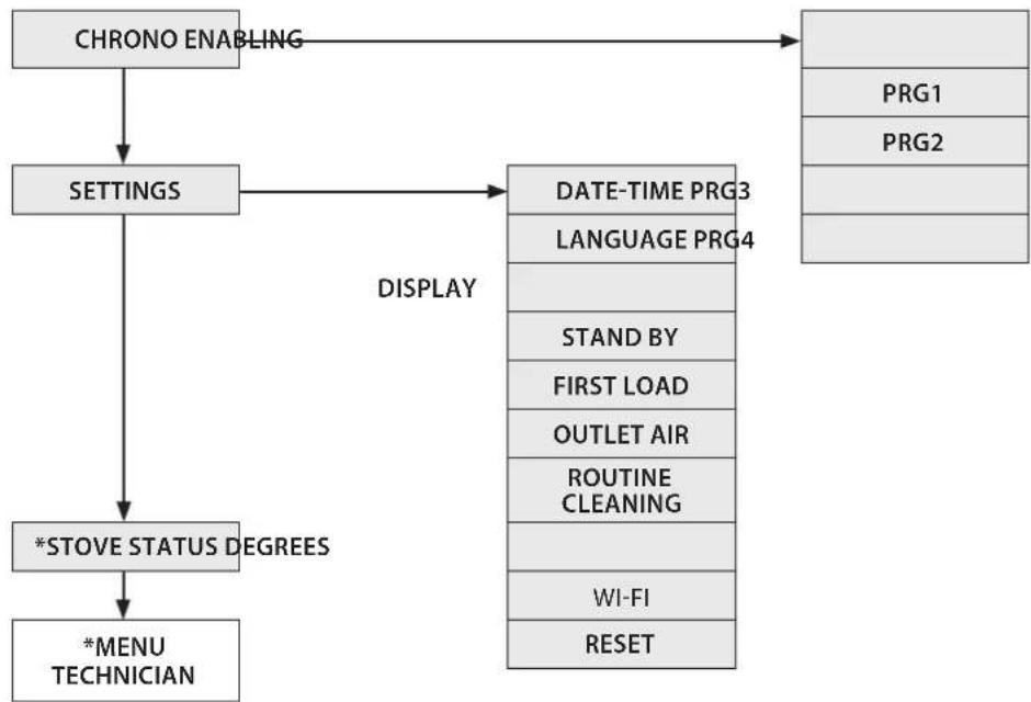
flowchart
graph TD
    A["CHRONO ENABLING"] --> B["SETTINGS"]
    B --> C["*STOVE STATUS DEGREES"]
    C --> D["*MENU TECHNICIAN"]
    E["PRG1"] --> F["DATE-TIME PRG3"]
    G["PRG2"] --> H["LANGUAGE PRG4"]
    I["STAND BY"] --> J["OUTLET AIR"]
    K["FIRST LOAD"] --> L["ROUTINE CLEANING"]
    M["WI-FI"] --> N["RESET"]
    O["DISPLAY"] --> P["DESCRIPTION"]
*TECHNICIANS ONLY
GENERAL wARNINGS
Advice to follow for the first start-ups of the product:
During the first hours of operation, there may be some smoke or odours, but they are due to the normal "thermal break-in" process. During this process, the duration of which changes depending on the product, it is recommended to:
♦ Ventilate the room well
- If present, remove any majolica parts from the top of the product
◆ Activate the product at the maximum power and temperature
- Avoid remaining in the room for a long time
Do not touch the surfaces of the product
Notes:
The process is completed after a few heating/cooling cycles.
Do not use for the combustion of elements or substances other than those indicated in the manual.
Before turning on the product, it is necessary to perform the following checks:
- If it is intended to be connected to a hydraulic system, it must be complete and fully functional and in compliance with the instructions given in the product manual and with the relevant regulations in force.
The pellet hopper must be completed loaded
◆ The combustion chamber and the burn pot must be clean
Make sure that the fire holder, the ash pan and the pellet hopper close hermetically (if present in the hermetic version); they must be closed and there must be no foreign bodies in the sealing elements and gaskets.
- Check that the power cord is properly connected
- The bipolar switch (if present) must be set to position "1".

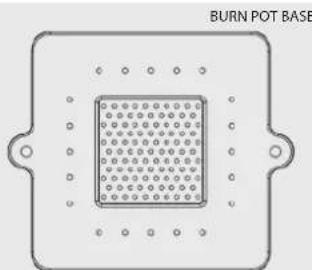
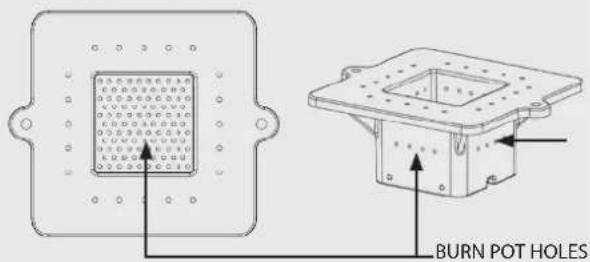
mAe SURE THAT THE BOTTOM OF THE BURN POT IS fREE FROM RESIDUE AND DEPOSITS. THE HOLES AT THE BOTTOM must BE COMPLETELY FREE TO GUARANTEE PROPER COMBUSTION.
natural_image
Pure diagram of a rectangular component with a central grid pattern and mounting holes (no text or symbols)FIRST IGNITION SETTINGS
Once the power cord at the back of the stove has been connected, move the switch, also located on the back, to (I).
The switch at the back of the stove powers the stove board.
The stove remains off and a first screen appears on the panel reading OFF.
DATE-TImE
This menu allows the date and time to be set.
CONTROLS PROCEDURE
- Press key 6.
- Press key 3 until SETTINGS appears and confirm by pressing key 6.
- Confirm DATE-TIME by pressing key 6 and using keys 4 and 5 to set the day.
◆ Continue by pressing key 6.
Use the same procedure with 4 or 5 to choose the setting and 6 to move continue, to set the hour, minutes, date, month and year. - Press key 6 to confirm and key 1 to scroll back through the menus until the initial page.
LANGUAGE
This menu allows the preferred language to be selected.
The available languages are: Italian - English - German - French - Spanish - Portuguese -- Danish - Estonian - Croatian - Slovenian.
CONTROLS PROCEDURE
- Press key 6.
- Press key 3 until SETTINGS appears and confirm by pressing key 6.
- Press key 3 until LANGUAGE appears and confirm by pressing key 6.
- Select the language using keys 4 or 5.
- Press key 6 to confirm and key 1 to scroll back through the menus until the initial page.
DEGREES
This menu allows you to set the unit of measure for the temperature. The value is preset to °C.
CONTROLS PROCEDURE
- Press key 6.
- Press key 3 until SETTINGS appears and confirm by pressing key 6.
- Press key 3 until DEGREES appears and confirm by pressing key 6.
Use keys 4 -5 to select Celsius or Fahrenheit. - Press key 6 to confirm and key 1 to scroll back through the menus until the initial page.

DO NOT USE ANY fLAmMABLE LIQUIDS FOR IGNITION!
DO NOT ALLOW THE BAG OF PELLETS TO COmE INTO CONTACT WITH THE BOILING HOT STOvE DURING THE FILLING PHASE!
IN THE EvENT OF CONTINUED FAILURE TO LIGHT, CONTACT AN AUTHORISED TECHNICIAN.

NO IGNITION
THE APPLIANCE mAY FAIL TO LIGHT BECAUSE THE AUGER IS EmPTY AND NOT ALWAYS ABLE TO LOAD THE BURN POT FAST ENOUGH WITH THE PELLETS NEEDED FOR NORMAL IGNITION. IF THE PROBLEM OCCURS AFTER ONLY A fEw MONTHS OF OPERATION, CHECK THAT THE ROUTINE CLEANING DESCRIBED IN THE STOVE HANDBOOK HAS BEEN CARRIED OUT CORRECTLY
OPERATION AND LOGIC
IGNITION
Once the points listed previously have been checked, press key 1 for three seconds to ignite the stove. 15 minutes are available for the ignition phase. After ignition and having reached the control temperature, the stove interrupts the ignition phase and passes to STARTING.
PREPARATION
During the start-up phase, the stove stabilises combustion, increasing it progressively, to then start ventilation and pass on to WORK.
WORK
During the work phase, the stove reaches the set power set; see following item.
SET POWER
Set the operating power from 1 to 5 (using keys 2 and 3).
Power 1 = minimum level - Power 5 = maximum level.
SET H2O
Set the boiler temperature from 65 to 80^ (using keys 4 and 5).
PUMP OPERATION
The pump is activated when the internal water temperature reaches 60^ C. Since the pump is always in operation above 60^ C, it is advisable to keep a heating area always open so that the product operates in a more homogeneous manner and in order to prevent stoppages due to overtemperature. This area is usually called "safety area".
BURN POT CLEANING
At preset intervals, the generator cleans the burn pot, turning the machine off.
When the cleaning phase is finished, the generator will re-start automatically and continue the working phase, returning to the selected power level.
BLOW
During the working phase, the stove has an internal timer, which after a pre-set period of time cleans the burn pot.
This phase is shown on the display, it lowers the stove power level and increases the flue gas exhaust motor for a programmed period of time. When the cleaning phase is finished, the stove will re-start automatically and continue the working phase, returning to the selected power level.
MODULATION and H-OFF
As the water temperature approaches the set point, the boiler starts to modulate automatically bringing itself to the minimum power. If the temperature increases beyond the set point, it will automatically switch off indicating H-OFF, and will automatically go back on when the temperature drops below the set point.
SWITCH-OFF
Press key 1 for three seconds.
Once this operation has been performed, the appliance automatically enters the switch-off phase, blocking the supply of pellets.
The flue gas exhaust motor and the hot air flow motor will remain on until the stove temperature has dropped below the default parameters.
REIGNITION
The stove can only be re-ignited automatically or manually when the cooling cycle conditions and the preset timer have been satisfied.

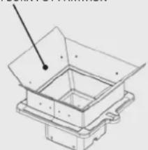
IT IS PROHIBITED TO USE THE APPLIANCE WITHOUT THE PARTITION AND/OR FLAME GUARD (SEE FIGURE ON SIDE). REMOVAL WILL COMPROMISE THE SAFETY OF THE PRODUCT AND RESULT IN THE IMMEDIATE NULLIFICATION OF THE WARRANTY PERIOD. IN THE CASE OF WEAR OR DETERIORATION, REQUEST AFTER-SALES ASSISTANCE TO REPLACE THE PART (REPLACEMENT IS NOT COVERED BY THE WARRANTY AS THE COMPONENT IS SUBJECT TO WEAR).
Upper BURN POT PARTITION
natural_image
Technical line drawing of a mechanical housing or bracket assembly (no text or symbols)STAND-BY - ADDITIONAL THERMOSTAT
N.B.: INSTALLATION MUST BE PERFORMED BY AN AUTHORISED TECHNICIAN
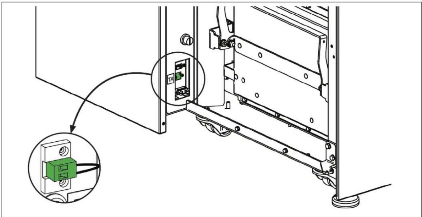
It is possible to control the temperature of a room adjacent to the room where the stove is positioned; simply connect a thermostat following the procedure described in the following section (it is advisable to place the optional mechanical thermostat at a height off the ground equal to 1.50 m). Stove operation with the external thermostat connected in the clamp TA can be different depending on the activation or deactivation of the STAND-BY function.
By factory default, the clamp TA is jumpered, therefore it always has closed contact (on request).
ADDITIONAL THERMOSTAT FUNCTIONING WITHSTAND-BY ACTIVE
When the STAND-BY function is active, the STBY icon will be on. When the contact or external thermostat is not satisfied (open contact / temperature reached), the stove will switch off. As soon as the contact or external thermostat switches to the "not satisfied" status (closed contact / temperature to be reached) it will re-ignite.
NB: stove operation depends on the temperature of the water inside the stove and relative factory setting restrictions. If the stove is in H-OFF (water temperature reached), any additional contact or thermostat request will be ignored.
ADDITIONAL THERMOSTAT OPERATION WITHSTAND-BY DEACTIVATED
When the STAND-BY function is not active, the STBY icon will be off.
When the contact or external thermostat is satisfied (open contact / temperature reached), the stove will go to minimum. As soon as the contact or external thermostat switches to the "not satisfied" status (closed contact / temperature to be reached) the stove will start to work again at the pre-set power.
NB: stove operation depends on the temperature of the water inside the stove and relative factory setting restrictions. If the stove is in H-OFF (water temperature reached), any additional contact or thermostat request will be ignored.
ADDITIONAL THERMOSTAT INSTALLATION
- Switch the appliance off using the master switch positioned on the rear of the stove.
- Remove the plug from the socket.
- Refer to the wiring diagram and connect the two thermostat wires in the relevant terminals located on the back of the stove, one red and one black (clamp TA). In each model, the position or colour of the terminals may be different. The picture is for illustrative purposes only.

TO ACTIVATE STAND-BY, REFER TO THE "SETTINGS" CHAPTER
text_image
Technical diagram showing a mechanical assembly with labeled components and a magnified inset of a green component.CHRONO

This function allows stove ignition and switch-off to be automatically programmed.
The factory setting for CHRONO is off.
The chrono allows the programming of 4 time slots per day, which can be used every day of the week.
For each time slot, it is possible to set ignition and switch-off times, specific days of application, desired temperature and set power.
Current day and time settings are essential for the correct operation of the Chrono.
Recommendations
Before using the chrono function, you must set the current day and time, so check that you have followed the points listed in the sub-chapter "DATE-TIME". To use the chrono function correctly, it must not only be programmed, but also enabled. The 4 time slots can be overlapped using the ignition and switch-off time settings. In this way, it is possible to create a combination of time slots with different temperatures and power levels, without changing the status of the stove.
N.B.: in the case of overlapping time slots, the stove will remain on until the last switch-off time.
ENABLING/DISABLING THE CHRONO
CONTROLS PROCEDURE
- Press key 6.
- Press 3 until CHRONO appears and confirm by pressing key 6.
- Confirm ENABLING by pressing 6.
Use keys 4 -5 to enable (ON) or disable (OFF) - Press key 6 to confirm and key 1 to scroll back through the menus until the initial page.
| CHRONO > ENABLING > PRG1 | On/off Enable/disable PRG 1 | |
| V | PRG2 | On/off Enable/disable PRG 2 |
| V | PRG3 | On/off Enable/disable PRG 3 |
| V | PRG4 | On/off Enable/disable PRG 4 |
| PRG1 > START PRG1 | OFF-00:00 PRG1 ignition time | |
| V | STOP PRG1 | OFF-00:00 PRG1 switch-off time |
| V | MONDAY...SUNDAY | On/off Enable/disable days PRG1 |
| V | SET PRG1 | 65°C - 80°C (149°F - 176°F) SET H2O PRG1 |
| V | POWER PRG1 | 1-5 Set power PRG1 |
| PRG2 > START PRG2 | OFF-00:00 Ignition time PRG2 | |
| V | STOP PRG2 | OFF-00:00 Switch-off time PRG2 |
| V | MONDAY...SUNDAY | On/off Enable/disable days PRG2 |
| V | SET PRG2 | 65°C - 80°C (149°F - 176°F) SET H2O PRG2 |
| V | POWER PRG2 | 1-5 Set power PRG2 |
| PRG3 > START PRG3 | OFF-00:00 Ignition time PRG3 | |
| V | STOP PRG3 | OFF-00:00 Switch-off time PRG3 |
| V | MONDAY...SUNDAY | On/off Enable/disable days PRG3 |
| V | SET PRG3 | 65°C - 80°C (149°F - 176°F) SET H2O PRG3 |
| V | POWER PRG3 | 1-5 Set power PRG3 |
| PRG4 > START PRG4 | OFF-00:00 Ignition time PRG4 | |
| STOP PRG4 | OFF-00:00 Switch-off time PRG4 | |
| MONDAY...SUNDAY | On/off Enable/disable days PRG4 | |
| SET PRG4 | 65°C - 80°C (149°F - 176°F) SET H2O PRG4 | |
| POWER PRG4 | 1-5 Set power PRG4 | |

If wEEkLY PROGRAmmer IS ACTive ON THE Command PANEL, A Small Icon IS DISPLAYED

EXAMPLE OF CHRONO OVERLAPPING TIMES/SLOTS
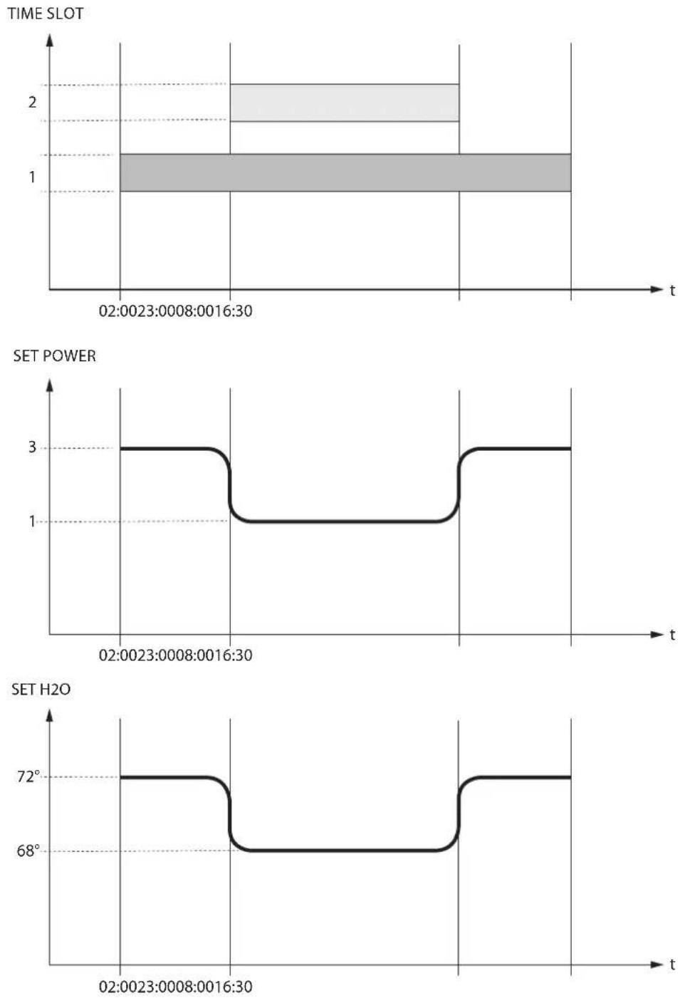
| Time slot 1 | start 02:00stop 23:00 | power 3 - SET H2O 72°C | |
| Time slot 2 | start 08:00stop 16:30 | power 1 - SET H2O 68°C | |
| stove operation | |||
SETTINGS
- DATE-TImE
- LANGUAGE
- SET DEGREES
See chapter: firSt ignition SettingS
DISPLAY
This menu allows you to adjust the brightness of the display. The values range from OFF, 1 to 20. If set to OFF, the display backlighting is set to maximum brightness and turns off after a 60 second delay.
The backlighting can be turned on again by pressing any key or if the stove is in alarm status.
CONTROLS PROCEDURE
- Press key 6.
- Press key 3 until SETTINGS appears and confirm by pressing key 6.
- Keep pressing key 3 until DISPLAY appears and confirm by pressing key 6.
◆ Use keys 4 -5 to set the desired intensity (SET) - Press key 6 to confirm and key 1 to scroll back through the menus until the initial page.
STAND - BY
The STAND-BY function, if enabled, is used when stove switch-off is to be controlled by means of an additional thermostat
CONTROLS PROCEDURE
- Press key 6.
- Press key 3 until SETTINGS appears and confirm by pressing key 6.
- Keep pressing key 3 until STAND-BY appears and confirm by pressing key 6.
◆ Use keys 4-5 to enable (ON) / disable (OFF).
◆ Press 1 several times to confirm and exit the menu
FIRST LOAD
This function allows the auger to be filled, thus facilitating first stove ignition phases, or in the event the pellet hopper is empty.
With the stove cold and "OFF", make sure the pellets have been introduced inside the hopper and activate the FIRST LOAD function, confirming by pressing OK.
To interrupt continuous loading, simply press key 1 for 3 seconds.
CONTROLS PROCEDURE
- Press key 6.
- press key 3 until SETTINGS appears and confirm by pressing key 6.
- Keep pressing key 3 until FIRST LOAD appears and confirm by pressing key 6.
- Press key 1 several times to confirm and exit the menu.
OUTLET AIR
This function allows any air in the stove to be discharged. By activating the pump function, it will be powered alternatively with 30 second work phases and 30" stop for 15 minutes. With the stove cold and in "OFF", activate the OUTLET AIR function, pressing key 6 to confirm. To interrupt, press and hold key 1 for 3 seconds.
CONTROLS PROCEDURE
- Press key 6.
- Press key 3 until SETTINGS appears and confirm by pressing key 6.
- Keep pressing 3 until OUTLET AIR appears and confirm by pressing 6.
- Press key 1 several times to confirm and exit the menu.
CLEANING THE COMBUSTION CHAMBER
This function allows to open the burn pot base, facilitating the combustion chamber cleaning operations.
CONTROLS PROCEDURE:
- Press key 6
- Press 3 until SETTINGS appears and confirm by pressing 6
- Keep pressing 3 until ROUTINE CLEANING appears and confirm by pressing 6
♦ Scrape the walls of the combustion chamber using the special tool supplied and let the residual ash drop into the ash drawer. - Press key 1 to end and wait for the main screen to reappear.
OPEN THE DOOR ONLY WHEN THE OPERATION IS COMPLETE! THE DISPLAY WILL INDICATE THAT THE DOOR HAS BEEN OPENED!
Wi-Fi
The display allows internet connection using Wi-Fi technology.
This allows remote management and control of the stove using the dedicated APP for Smartphones, "TotalControl 2.0" (Apple Store / Play Store).
WI-FI ENABLING CONTROLS PROCEDURE
- Press key 6.
- Press key 3 until SETTINGS appears and confirm by pressing key 6.
- Keep pressing key 3 until Wi-Fi appears and confirm by pressing key 6.
- Press key 6 to access ENABLING.
Use keys 4-5 to select enabling "ON"/ disabling "OFF" and press key 6 to confirm. - Press key 1 several times to exit the menu.
CONTROLS PROCEDURE TO RESET WI-FI CONFIGURATION AND ENABLE ACCESS POINT
- Press key 6.
- Press key 3 until SETTINGS appears and confirm by pressing key 6.
- Press key 3 until Wi-Fi appears and confirm by pressing key 6.
- Press key 3 until RESET appears and the press key 6.
Use keys 4-5 to select start reset "ON" / "OFF" and press key 6 to confirm. - Press key 1 several times to exit the menu.
RESET
Allows the user to reset all editable values to the default values.
CONTROLS PROCEDURE
- Press key 6.
- Press key 3 until SETTINGS appears and confirm by pressing key 6.
- Press key 3 until RESET appears and confirm by pressing key 6.
Use keys 4-5 for enabling "ON" or disabling "OFF" - Press key 1 several times to confirm and exit the menu.
AUX
If the producer's conveyed wave accessories are used, the connection must be made by the qualified technician directly in the board. Contact the dealer for further details.
OPTIONAL ADDITIONAL BOARD (STANDARD ON PR20 AND PR30)
The manufacturer has an optional additional board which allows the boiler to have the following additional system management functions. The table below indicates the various possibilities that the optional can offer.
| DHW Storage Management | √ |
| Buffer Tank management | √ |
| 3 heating areas | √ |
| Instant DHW option | √ |
| Buffer tank pump or 4th heating area management | √ |
| Anti-legionella management for DHW storage | √ |
| DHW storage chrono management | √ |
| Auxiliary output management and control | √ |
to find out where your nearest service centre is, contact your dealer or visit the website: www.lanordica-extraflaMe.coM
CLEANING AND MAINTENANCE
ALWAYS FOLLOW THE INSTRUCTIONS IN COMPLETE SAFETY!
Make sure that the power cord is unplugged because the generator May have been prograMMed to switch on.
◆ that the generator is cold all over.
- that the ashes are coMpletely cold.
- ensure efficient air exchange in the rooM during product cleaning operations.
- poor cleaning will coMproMise correct operation and safety!
MAINTENANCE
For correct operation, the generator must undergo routine maintenance by a qualified technician, at least once a year.
The periodic inspection and maintenance operations must always be performed by specialised, qualified technicians, who operate in accordance with the laws in force and the instructions given in this use and maintenance manual.

EVERY YEAR, HAVE THE FUME EXTRACTION SYSTEM, FLUE PIPES AND "T" FITTINGS, INCLUDING THE INSPECTION CAPS CLEANED. IF PRESENT, ALSO CLEAN THE ELBOWS AND HORIZONTAL SECTIONS!
THE GENERATOR CLEANING FREQUENCY IS INDICATIVE! IT DEPENDS ON THE QUALITY OF THE PELLETS AND FREQUENCY OF USE.
THESE OPERATIONS MAY SOMETIMES NEED TO BE PERFORMED MORE OFTEN
PERIODIC CLEANING UNDER USER'S RESPONSIBILITY
The periodic cleaning operations, as indicated in this use and maintenance manual, must be performed with the utmost care after reading the instructions, procedures and frequency described in this use and maintenance manual.
CLEANING THE SURFACES AND COVERING
Never use abrasive or chemically aggressive detergents for cleaning!
The surfaces must be cleaned when the generator and covering are completely cold. For the maintenance of the surfaces and metal parts, simply use a cloth dampened with water or water and neutral soap.
Failure to comply with these instructions may damage the surfaces of the generator and cause the invalidation of the warranty.
CLEANING THE CERAMIC GLASS
Never use abrasive or chemically aggressive detergents for cleaning!
The ceramic glass must be cleaned when the glass is completely cold.
To clean the ceramic glass, simply use a dry brush and some damp newspaper dipped in ash. If the glass is very dirty, use a specific cleaning agent for ceramic glass. Spray a small amount on a cloth and use it on the ceramic glass. Do not spray the cleaning agent or any other liquid directly on the glass or seals!
Failure to comply with these instructions may damage the surfaces of the ceramic glass and cause the invalidation of the warranty.
CLEANING THE PELLET HOPPER
When the hopper is completely empty, disconnect the power cord of the generator, remove the residue (dust, chippings, etc.) from the empty hopper and then fill it up.

THE PELLET HOPPER GASKETS, BURN POT AND FIRE DOOR GUARANTEE CORRECT STOVE OPERATION. THESE NEED TO BE PERIODICALLY CHECKED BY THE USER. IF THEY ARE WORN OR DAMAGED, IMMEDIATELY REPLACE THEM. THESE OPERATIONS MUST BE CARRIED OUT BY A QUALIFIED TECHNICIAN.

IF THE POWER CORD IS DAMAGED, IT MUST BE REPLACED BY THE SERVICE CENTRE OR BY A SIMILARLY QUALIFIED PERSON, SO AS TO AVOID ALL RISKS.
burn pot and Combustion Chamber
By means of a mechanical system, the burn pot is cleaned automatically at preset intervals. It is however advisable to remove any residues by means of a vacuum cleaner.
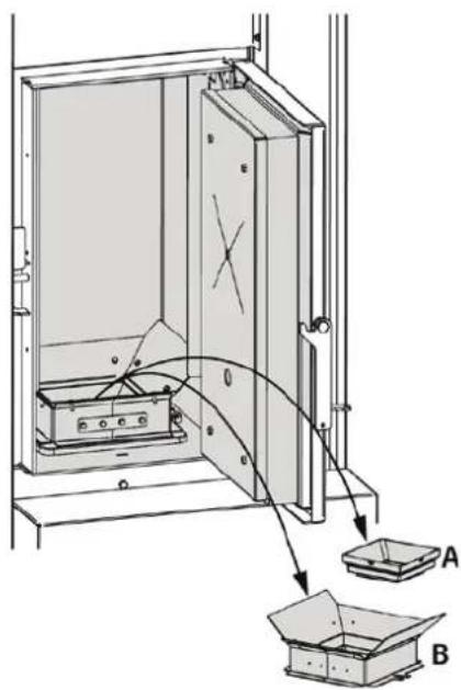
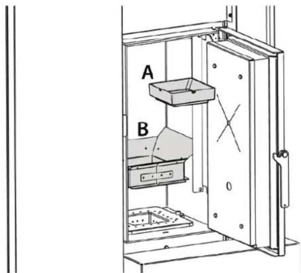
- Remove the assembly made up of the internal cone (A) and the ash conveyor (B).
- Clean the combustion chamber and the bottom of the burn pot completely, using a suitable vacuum cleaner.
text_image
Technical diagram showing a mechanical assembly with labeled components A and B, including a component inside a housing.Cleaning the Combustion Chamber tube bundle
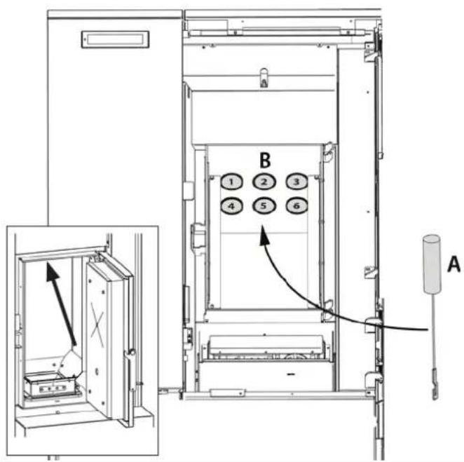
Clean the 6 tube bundles (B) of the combustion chamber using the brush supplied (A).
It is advisable to use a suitable vacuum cleaner during the operation.
text_image
B 1 2 3 4 5 6 Adetails on burn pot Cleaning
To clean the burn pot, simply remove the central cone (A), lift the flame guard (B) and rotate it to remove it completely. Perform the same operation in reverse order to re-assemble. After having re-positioned, always make sure:
- that the cone (A) has been inserted in the correct direction (see figure);
- that the ash conveyor (B) rests on the burn pot correctly, and not on another area of the combustion chamber.
text_image
A B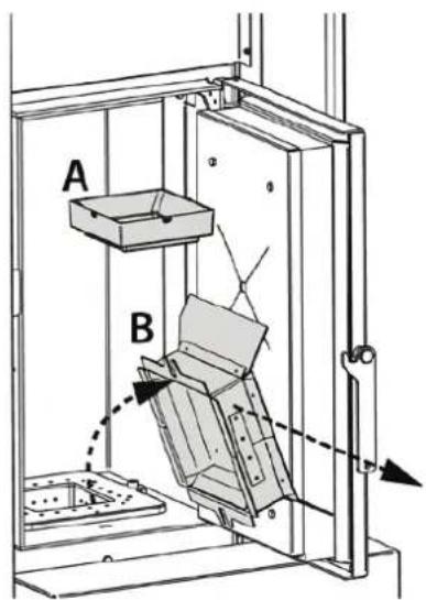
text_image
A B
a Clean burn pot guarantees CorreCt operation!
by keeping the burn pot and its holes Constantly Clean and free of Combustion residue, exCellent Combustion is guaranteed over time, thus preventing any generator malfunCtions that may reQuire teChniCal assistanCe.
BURN POT BASE
text_image
BURN POT HOLESash drawer
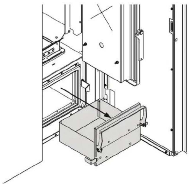
(pk version)
- Turn off the boiler
- Remove the ash drawer and empty it into a suitable container.
natural_image
Technical line drawing of a mechanical assembly with no visible text or symbolsash CompaCtor
(for pr version only)
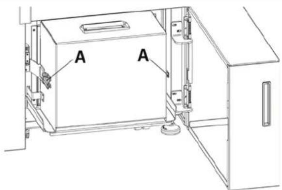
- Turn off the boiler
- Release the compactor from the boiler by means of the two lateral levers (A).
- Close the cap (B) on the auger insertion hole (to prevent ash from falling while it is being moved)
- Release the cap (C) and empty out the ash.
- Close the cap (C).
- Open the hole (B) to insert the auger and insert the compactor.
- Secure the compactor by means of the two lateral levers (A).
text_image
A A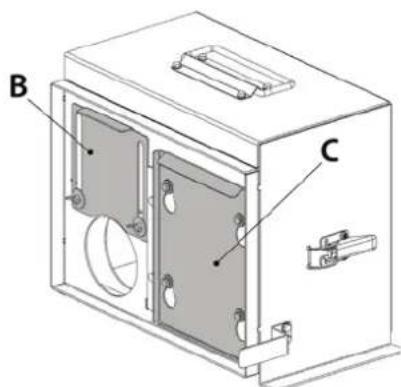
text_image
B CCLEANING AND MAINTENANCE SUMMARY TABLE
| USER CLEANING | FREQUENCY - EVERY X *PALLET CUNSUMED | |
| BURN POT COMBUSTION CHAMBER | PK15 1 | |
| PK20 1 | ||
| PK30 1 | ||
| PR20 2 | ||
| PR30 2 | ||
| ASH DRAWER (PK) | PK15 1 | |
| PK20 1 | ||
| PK30 1 | ||
| **CLEANING THE ASH COMPACTOR (PR) | PR20 2 | |
| PR30 2 | ||
| CLEANING THE COMBUSTION CHAMBER TUBE BUNDLE | PK-PR | 3 |
*1 Pallet = 1050kg
| QUALIFIED TECHNICIAN | FREQUENCY - EVERY XX MONTHS | |
| CLEANING THE EXCHANGER PK-PR 12 | ||
| T-SHAPED FITTING/ FLUE PIPE PK-PR 6 | ||
| GASKETS PK-PR 12 | ||

**COMPACTOR CLEANING: IN CASE OF PROLONGED BOILER INACTIVITY (MORE THAN 60 DAYS) CHECK THAT THE ASH IN THE COMPACTOR HAS NOT BEEN SOLIDIFIED BY MOISTURE.

THE GENERATOR CLEANING FREQUENCY IS INDICATIVE! IT DEPENDS ON THE QUALITY OF THE PELLETS AND FREQUENCY OF USE. THESE OPERATIONS MAY SOMETIMES NEED TO BE PERFORMED MORE OFTEN
ROUTINE MAINTENANCE PERFORMED BY QUALIFIED TECHNICIANS
Routine maintenance must be performed at least once a year.
Given the generator uses pellets as solid fuel, it requires annual routine maintenance, which must be performed by a Qualified technician, using only original spare parts.
Failure to comply may jeopardise safety of the appliance and invalidate the warranty conditions.
By observing the cleaning schedule reserved to the user described in the use and maintenance manual, the generator will be guaranteed correct combustion over time, thus preventing any faults and/or malfunctions which may require subsequent technical assistance. Requests for routine maintenance are not covered by the warranty.
DOOR, ASH DRAWER AND BURN POT GASKETS
The gaskets ensure the proper sealing of the stove and therefore its proper operation.
They must be periodically checked and immediately replaced if worn or damaged.
These operations must be carried out by a qualified technician.
CONNECTION TO THE FLUE
Annually, or in any case each time the flue pipe needs to be vacuumed and cleaned. If there are horizontal sections, the residue must be removed to prevent it from obstructing the flow of fumes.
SHUT-DOWN (END OF SEASON)
At the end of each season, before turning the stove off, it is advisable to completely empty the pellet hopper, removing any pellet residue and dust with a vacuum cleaner.
IT IS ADVISABLE NOT TO DISCONNECT THE HEAT GENERATOR FROM THE ELECTRICAL POWER SUPPLY IN ORDER TO ALLOW THE PUMP TO PERFORM THE NORMAL ANTI-BLOCKING CYCLES.
Routine maintenance must be performed at least once a year.
routine maintenantCe
THE PICTURES ARE FOR ILLUSTRATIVE PURPOSES ONLY.
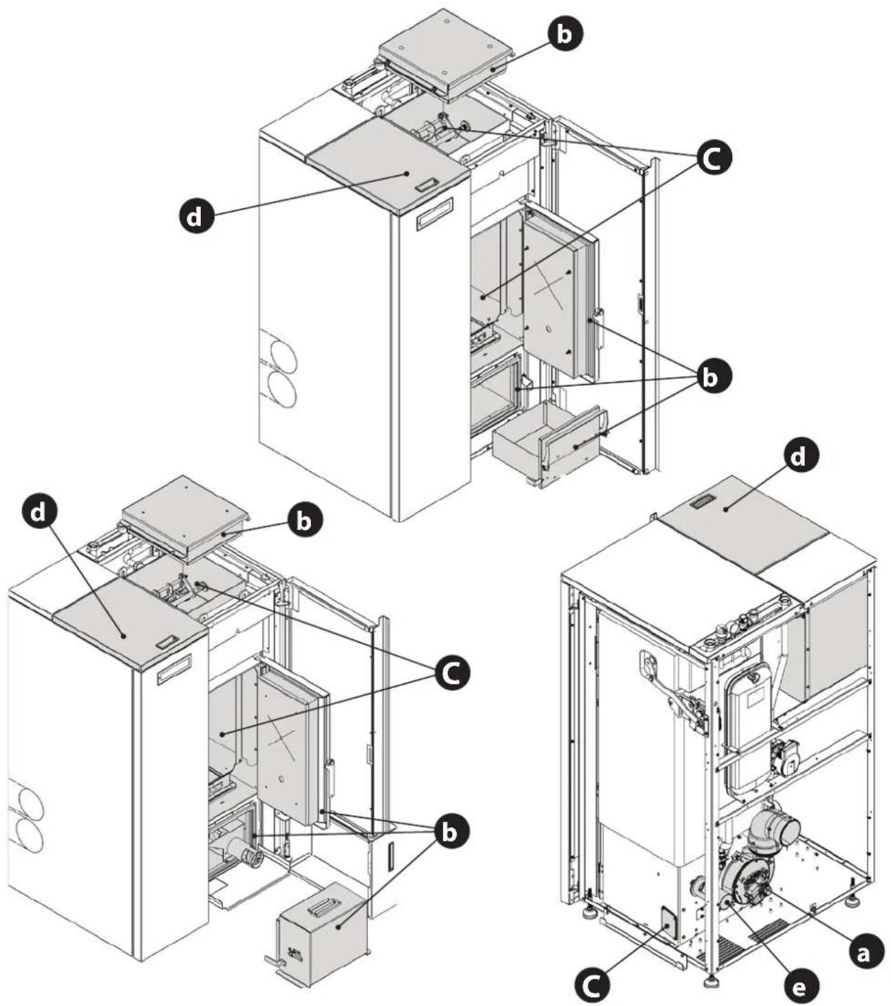
text_image
Technical diagram of an appliance system with labeled components (a-e) for assembly or maintenance reference.| a | Fumes motor (disassembly and cleaning and fumes pipe and "T"), new silicone in the provided points |
| b | Inspections of gaskets, ash drawer and door (replace them and apply silicone where envisioned) |
| C | Combustion chamber and heat exchanger (full cleaning) including ignition plug pipe |
| d | Hopper (complete emptying and cleaning). |
| e | Check air intake pipe and cleaning of the flow sensor |
| DISPLAY | |
| DISPLAY | REASON |
| OFF | Generator off |
| START | The start-up phase is in progress |
| PELLET LOADING | Continuous pellet loading is in progress during the ignition phase |
| IGNITION | The ignition phase is in progress |
| PREPARATION | The preparation phase is in progress. |
| WORK | The normal work phase is in progress. |
| MODULATION | The generator is working at minimum. |
| BLOW | The automatic blow is active. |
| BURN POT CLEANING | The routine cleaning of the burn pot is in progress. |
| FINAL CLEANING | The final cleaning is in progress. |
| STAND-BY | Generator off waiting for re-ignition due to an external thermostat. |
| COOLING WAITING TIME | The generator is required to turn on during the switch-off phase. If activated, the generator will turn on automatically as soon as the safety conditions allow it. |
| H-OFF | Generator off due to water temperature over set. |
| T-OFF | Generator off waiting for re-ignition due to all requests met |
| WAITING BLACK OUT | The generator is cooling after a power cut.Once cooling is completed, it will re-start automatically |
| ANTI-FREEZING | The anti-freezing function is in progress as the H2O temperature is below the factory set threshold the pump is active until the water reaches the pre-set factory parameter +2°C |
| ANTI-BLOCK | The pump anti-block function is in progress (only if the generator has been in an OFF state for at least 96 hours); the pump is activated for the time pre-set by the manufacturer, in order to prevent it from blocking |
| EXCHANGER BLOCKED | The movement of the exchangers is blocked.Switch off the machine and clean the exchangers. If the problem persists, contact the after-sales centre. |
| ASH KIT CHECK | The ash extractor is blocked.Switch off the machine and empty out the ash drawer.If the problem persists, contact the after-sales centre. |
| ALARMS | ||
| DISPLAY | EXPLANATION SOLUTION | |
| Indicates the presence of an alarm. | On: indicates the presence of an alarmFlashing: indicates the deactivation of the depression sensor.The alarm can be reset only if the fumes motor has stopped and 15 minutes have passed since the alarm was displayed, by pressing the key 1/ ⏻ for 3 seconds. | |
| FUMES MOTOR FAULT | Fumes motor fault Contact after-sales centre | |
| FUMES PROBE | Fumes probe fault. Contact after-sales centre | |
| HOT FUMES | High fumes temperature Contact after-sales centre | |
| CHAMBER PROBE | Chamber probe fault. Contact the after-sales centre. | |
TO FIND OUT WHERE YOUR NEAREST SERVICE CENTRE IS, CONTACT YOUR DEALER OR GO TO THE WEBSITE WWW.LANORDICA-EXTRAFLAME.COM
| NO FLAME | The pellet hopper is empty.No pellet feed.The gearmotor does not feed pellets. | Check for the presence of pellets in the hopper.Contact after-sales centre |
| DEPR ALARM | The door is not closed correctly.The ash drawer is not closed correctly.The combustion chamber/ tube bundle is dirty.The fumes exhaust pipe is blocked/dirty | Check hermetic door closure.Check hermetic closure of the ash drawer.Check cleanliness of the fumes pipe and the combustion chamber/ tube bundle. |
| NO IGNITION | The pellet hopper is empty.Pellet feed calibration inadequate Thermostat bulbs tripped. | Check for the presence of pellets in the hopper.Contact after-sales centre.Check the procedures described in the “Ignition” chapter.Check bulb thermostats (see chapter on Resetting) |
| NO IGNITION BLACK OUT | No current during the ignition phase. | Take the stove to OFF conditions using key 1 and repeat the procedure described in the “Ignition” chapter. |
| AUGER COMMAND | Abnormal pellet loading. Contact after-sales centre | |
| AUGER BLOCKED | Abnormal operation of pellet motor Contact after-sales centre | |
| MAX ELECTRICAL CURRENT | The automatic cleaning of the burn pot is blocked. Burn pot dirty or clogged or door not closed properly | Check that the door is closed properlyCheck that the burn pot is free and cleanIf the problem persists, contact the after-sales centre. |
| H2O PROBE | H2O probe fault Contact after-sales centre | |
| * DHW PROBE | Fault in DHW probe. Contact after-sales centre | |
| * BUFFER TANK PROBE | Fault in Buffer tank probe. Contact after-sales centre | |
| CLOSE HOPPER - STOVE DOOR | Pellet hopper open.Stove door open.Air inlet clogged or dirty. | Check that the pellet hopper and the combustion chamber door are closed correctly.Make sure that the compactor is installed correctly.Check air inlet. |
| BLOCKED PWM ALARM | The pump has stopped permanentlyPump blocked. Electronic module damaged | Contact after-sales centre |
| HOT PWM ALARM | The pump is operating but not with good performance. Undervoltage 160-194V.Pump in circuit breaker protection mode. | Contact after-sales centre |
| STOPPED PWM ALARM | The pump has stopped but is still operational.Undervoltage < 160V. Overvoltage.Unexpected external flow. | Contact after-sales centre |
| STOPPED 2 PWM ALARM | The pump has stopped but is still operational.Problem in a component different to the pump.Debris in installation.Positioning in high temperature. | Contact after-sales centre |
| FLOW PWM ALARM | Pump blocked.Liquid with high density.Pipe obstructed.Presence of air in the system. | Contact after-sales centre |
| PWM INTERFACE ALARM | IPWM output interface damaged, in short circuit or not connected | Contact after-sales centre |
| TRAPDOOR BLOCKED | The automatic cleaning of the burn pot is blocked.Burn pot dirty or cloggedThe door is not closed properly. | Make sure that the door is closed properly. Make sure that the burn pot is clear and clean.The automatic cleaning of the burn pot is blocked.If the problem persists, contact the service centre |
| EMPTY HOPPER | The pellet hopper is empty.The door is not closed properly.The ash drawer is not closed properly.The combustion chamber is dirty.The fume exhaust duct is blocked.. | Check for the presence of pellets inside the hopper.Check the hermetic closure of the door.Check the hermetic closure of the ash drawer.Make sure that the fumes duct, the primary air duct sensor and the combustion chamber are clean.Contact customer service |
| FAULT ALARM DELTA-P | Digital pressurestat warn or disconnected. Contact after-sales centre |
* if there is an additional system data-sheet.
TO FIND OUT WHERE YOUR NEAREST SERVICE CENTRE IS, CONTACT YOUR DEALER OR GO TO THE WEBSITE WWW.LANORDICA-EXTRAFLAME.COM
GUARANTEE TERMS
- EXTRAFLAME S.p.A. products are guaranteed, within the European community, for 24 months from the date of purchase.
Purchase has to be proved by means of a valid fiscal document issued by the seller (receipt, invoice or shipment document) identifying the purchased product and its purchase and/or delivery date.
WARNING: This conventional guarantee does not replace the guarantee regulated by the European legislation on consumer rights.
The conventional guarantee is only applicable to the Italian region and to those areas, within the European Community, where the Authorised Technical Assistance Centres are active (see the www.lanordica-extraflame.com website)
It is also limited to the state of residence of the consumer, which must coincide with the premises and/or registered office of the seller of the EXTRAFLAME S.p.A. product
These regulations do not apply if the product is purchased within commercial, entrepreneurial, or professional circumstances. In these cases the product guarantee will be limited to a period of 12 months from the date of purchase.
ITALIAN GUARANTEE
What must be done if there is a product malfunction:
Consult the instructions manual to make sure the malfunction cannot be solved by using the product correctly. Make sure the malfunction is included in those covered by the guarantee; otherwise the cost of the intervention will be borne entirely by the consumer. When requesting the intervention of the Assistance service at the Authorised Assistance Centre, always specify: - type of malfunction - model of the appliance - complete address - phone number
EUROPEAN GUARANTEE
What must be done if there is a product malfunction:
Consult the instructions manual to make sure the malfunction cannot be solved by using the product correctly. Make sure the malfunction is included in those covered by the guarantee; otherwise the cost of the intervention will be borne entirely by the consumer. Request the intervention of the Assistance service or the address of the Authorised Technical Assistance Centre to the seller; always specify: type of malfunction, model of the appliance, complete address and phone number
If the malfunction arises in the first 6 months of the product's life, the consumer has the right to have the product repaired with no expense. From the seventh to the twenty-fourth month, if a malfunction arises, the consumer will bear the cost of the call, while the seller will pay for the manpower and for any spare parts used.
- If the malfunction is linked to external events and/or conditions such as, including but not limited to, insufficient capacity of the systems; wrong installation and/or maintenance by the personnel which hasn't got the skills prescribed by the laws of the country of residence of the consumer; negligence; inability to use the product and wrong maintenance by the consumer, with respect to what is reported and recommended by the instructions manual of the product, which is part of the sales contract, this guarantee will be void.
Damage to the product that cannot be related to manufacturing defects are also not included in this guarantee. Similarly are excluded defects related to incorrect operation of the flue, according to the legislation in force in the country at the moment of purchase. Other exclusions include all product defects due to carelessness, accidental breakdown, tampering and/or damage during transport (scratches, dents, etc.), interventions carried out by unauthorised personnel and further damage caused by incorrect interventions by the consumer trying to arrange the initial malfunction.
The following consumables are excluded by the guarantee: gaskets, ceramic or tempered glasses, cast iron grilles or coatings, refractory materials (e.g. Nordiker or others), painted, chrome-plated or golden parts, majolica ware, handles, the brazier and its related components. For Idro products the heat exchanger is not covered by the guarantee if a suitable condensation-proof circuit is not set up to ensure a return temperature of the device of at least 55^ C. The guarantee excludes all the external components on which the consumer can directly operate during use and/or maintenance or that can be subject to wear and/or rust and stains on steel due to aggressive detergents.
If malfunctions are signalled which are not later confirmed during check by an authorised technician, the cost of the intervention will be borne entirely by the consumer.
-
If it is not possible to restore product conformity by repairing it, the product/component will be replaced, the guarantee expiration date and conditions will remain the same established when the product/component to be replaced has been purchased.
-
EXTRAFLAME S.p.A. cannot be held liable for injury or damage which may - either directly or indirectly - be caused to persons, animals and property ensuing from failure to observe all the instructions provided in the relevant instruction manual and the warnings regarding installation, use and maintenance of the product, that can also be downloaded on the website.
-
Interventions for adjusting and/or regulating the product for the type of fuel or other reasons are excluded by the guarantee.
-
If the product is repaired in one of the Authorised Technical Assistance Centres indicated by EXTRAFLAME S.p.A. and if the product is replaced, transport will be free of charge. If the technician can repair the product at the user's place of residence and they refuse, transport to the workshop and redelivery will be paid by the consumer.
-
After the 24 months of the guarantee have elapsed any repair intervention cost will be completely borne by the consumer.
-
In the case of disputes the only competent court is that of the EXTRAFLAME S.p.A. registered office - (Vicenza-Italy)
Additional warnings
- Only use the fuel recommended by the manufacturer. The product must not be used as an incinerator.
- Do not use the product as a ladder or supporting structure.
Do not place laundry on the product to dry it. Any clothes-horse or similar objects must be kept at due distance from the product. Danger of fire or damage to the coating.
The user is fully liable for any incorrect use of the product. The manufacturer bears no civil or criminal liability for incorrect use. - Unauthorised tampering of any nature or replacement of spare parts of the product with non-original parts may endanger the operator and the manufacturer bears no civil or criminal liability for this.
- Large parts of the surface of the product can get very hot (door, handle, glass, smoke outlet pipes, etc.). Please therefore avoid coming into contact with these parts without wearing suitable protective clothing or using appropriate measures, such as heat protective gloves.
- DO NOT use the product with the door open or if the glass is broken.
- The product must be electrically connected to a system equipped with an operational earthing system.
- Turn off the product in the event of a failure or malfunctioning.
- Unburned pellets that build up in the burner following each failed start-up must be removed before attempting to start up the product again. Make sure that the burner is clean and correctly positioned before starting it up again.
Do not wash the product with water. Water may penetrate into the unit and cause faults in the electrical insulation. This can cause electric shocks. - Installations not complying with the regulations in force, as well as incorrect use and failure to comply with the maintenance scheduled by the manufacturer, will invalidate the guarantee.
DiSpoSAI
INFORmATION FOR mANAGEmENT OF ELEcTRIc AND ELEcTRONIc APPLIANcE wAsTE cCONTAINING bATTERIEs OR AccUmULATORS
text_image
Warning symbol for a trash bin with crossed and unshaded lanes, indicating no waste or discharge.This symbol, which is used on the product, batteries, accumulators or on the packaging or documents, means that at the end of its useful life, this product, the batteries and the accumulators included must not be collected, recycled or disposed of together with domestic waste. Improper management of electric or electronic waste or batteries or accumulators can lead to the leakage of hazardous substances contained in the product. For the purpose of preventing damage to health or the environment, users are kindly asked to separate this equipment and/or batteries or accumulators included from other types of waste and to arrange for disposal by the municipal waste service It is possible to ask your local dealer to collect the waste electric or electronic appliance under the conditions and following the methods provided by national laws transposing the Directive 2012/19/EU.
Separate waste collection and recycling of unused electric and electronic equipment, batteries and accumulators helps to save natural resources and to guarantee that this waste is processed in a manner that is safe for health and the environment.
For more information about how to collect electric and electronic equipment and appliances, batteries and accumulators, please contact your local Council or Public Authority competent to issue the relevant permits.
Extraflame®
Riscaldamento a Pellet
ExtraflamE S.p.a. Via Dell'Artigianato, 12 36030 - MONTECCHIO PRECALCINO (VI) - ITALY
+39.0445.865911 - +39.0445.865912 - info@extraflame.it - www.lanordica-extraflame.com
MADE IN ITALY
design & production
TO FIND THE SERVICE CENTRE NEAREST TO YOU
CONTACT YOUR DEALER OR CONSULT
THE SITE WWW.LANORDICA-EXTRAFLAME.COM
The manufacturer reserves the right to vary the characteristics and the data reported in this pamphlet at any moment and without notice, in order to improve its products.
This manual, therefore, cannot be regarded as a contract towards other parties.