
HCE-RCAM-WRA - Rear Camera ALPINE - Free user manual and instructions
Find the device manual for free HCE-RCAM-WRA ALPINE in PDF.

| Product Type | Rear View Camera |
| Brand | Alpine |
| Model | HCE-RCAM-WRA |
| Compatible Vehicles | Jeep Wrangler JK (2007-2018), Jeep Wrangler Unlimited JK (2007-2018) |
| Camera Type | Color CMOS camera with wide-angle lens |
| Resolution | Approximately 480p (standard definition) |
| Viewing Angle | Approximately 170 degrees |
| Mounting Location | Spare tire bracket (stealth mount) |
| Power Supply | 12V DC (negative ground) |
| Power Consumption | Approximately 2W |
| Video Output | Composite video (RCA connector) |
| Waterproof Rating | IP67 (estimated) |
| Operating Temperature | -30°C to 60°C (estimated) |
| Main Cable Length | 7 meters (23 feet) extension cable included |
| Weight (approx.) | 0.5 kg (camera and bracket) |
| Dimensions (camera head) | Approximately 30x30x40 mm |
| Installation Difficulty | Moderate (professional installation recommended) |
| Key Features | Stealth spare tire mount, easy integration with Alpine head units, includes power & video unit |
| Safety Precautions | Disconnect battery before installation; avoid obstructing driver view |
| Spare Parts Available | Camera bracket, extension cable, retaining clips (contact Alpine) |
| Warranty | 1 year (typical, verify with seller) |
Frequently Asked Questions - HCE-RCAM-WRA ALPINE
User questions about HCE-RCAM-WRA ALPINE
0 question about this device. Answer the ones you know or ask your own.
Ask a new question about this device
Download the instructions for your Rear Camera in PDF format for free! Find your manual HCE-RCAM-WRA - ALPINE and take your electronic device back in hand. On this page are published all the documents necessary for the use of your device. HCE-RCAM-WRA by ALPINE.
USER MANUAL HCE-RCAM-WRA ALPINE
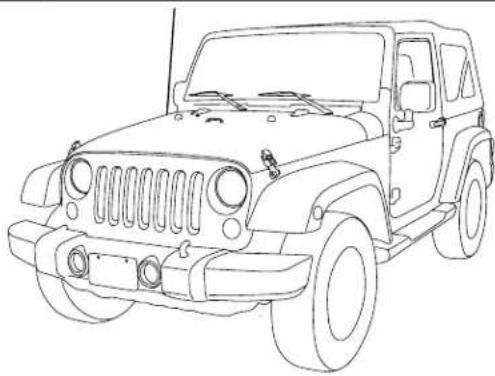
Jeep Wrangler HCE-RCAM-WRA Stealth-Mount Spare Tire Camera Installation Manual
● Model: Wrangler
● Model Year: 2007-2018
natural_image
Line drawing of a classic off-road vehicle (no text or symbols)Jeep
Model Year
Wrangler (JK) 2007-2018
Wrangler Unlimited (JK) 2007-2018
* The specified vehicles have been tested and have met compatibility specs at the time of testing. Compatibility is not guaranteed if the manufacturer has made production changes to the listed vehicles above.
⚠ Warning: Before you begin wiring, remove the ground wire from the negative terminal of the battery. Failing to do so can lead to electric shock, injury or damage to equipment.
Introduction
- Congratulations on purchasing the HCE-RCAM-WRA. This installation manual is designed to take you through the installation of HCE-RCAM-WRA. Please familiarize yourself with the owners manual and if you still have additional questions please call 1-800-TECH-101.
Note
- Design and specifications are subject to change without notice for improvement.
To Ensure Safe Use, Always Follow These Precautions
● The installation of this product requires specialized skills and experience. We recommend that you have the product installed by an Alpine authorized dealer.
- Before you use this product, be sure to carefully read this installation manual and the separate user's manual so that you can use the product correctly. Alpine Electronics bears no responsibility for problems that arise as a result of failure to follow the instructions in the manuals.
- This manual includes a number of symbols that are intended to help you use the product safely, to prevent harm to you and others, and to protect against damage to property. These symbols and their meanings are listed below. Make sure you fully understand these symbols before you begin reading the main text.
Explanations of Injury and Damage That May Result from Incorrect Use
 Warning Warning | Ignoring the content marked by this indication and using the product incorrectly is expected to lead to death or serious injury. |
 Caution Caution | Ignoring the content marked by this indication and using the product incorrectly is only expected to lead to injury or property damage. |
Types of Precautions
 Forbidden Forbidden | Indicates actions that are forbidden (must not be performed) |
 Forbidden Forbidden | Indicates that disassembly is forbidden. |
 Mandatory Mandatory | Indicates actions that are mandatory (must be performed) |
 | Marks content that should receive your full attention. |

Warning
Do not disassemble or modify the product. Doing so could lead to an accident, fire, or electric shock.

Forbidden
Store screws and other small objects where small children cannot reach them. If one of these small objects is swallowed, consult with a doctor immediately.

When replacing fuses, be sure to use fuses with the specified current rating. Failing to do so could lead to an accident or fire.

Forbidden

Mandatory
Only connect the product to a 12 VDC negative ground car. Failing to do so could lead to an accident or fire.

Mandatory
Before you begin wiring, remove the ground wire from the negative terminal of the battery. Failing to do so could lead to electric shock or injury.

Do not cut the insulation on a cord and take power from another device. Doing so could lead to fire or electric shock.

Forbidden
Do not install the product in a location where it will obstruct the driver's forward view; interfere with the operation of the steering wheel, gearshift, or the like; or pose a threat to passengers. Doing so could lead to an accident or injury.

Forbidden
When making a hole in the vehicle body, be careful to avoid damaging pipes, the fuel tank, electrical wiring, and the like. This kind of damage could lead to an accident or fire.

When installing and grounding the product, do not use any of the bolts or nuts of the steering wheel, brakes, fuel tank, or the like. Doing so could make the brakes stop working or lead to fire.

Forbidden
Do not install the product near the passenger-side airbag. Doing so could interfere with the operation of the airbag and lead to an accident or injury.

Forbidden
Bundle cords so that they don't interfere with driving. Wrapping cords around the steering wheel, gearshift, brake pedal, or the like, could lead to an accident or damage equipment.


Caution
Connect the product properly according to the instructions. Failing to do so could lead to fire or an accident.

Forbidden
Do not sandwich cords between the seat railing or allow them to touch protrusions. Resulting breaks or shorts could lead to electric shock or fire.

Do not block vents or heat sinks. Doing so could lead to fire or damage equipment.

Use the accessories according to the instructions, and attach them securely. Failing to do so could lead to an accident or damage equipment.

Forbidden
Do not install the product where it may be exposed to water or in a place with high levels of humidity or dust. Doing so could lead to fire or damage equipment.

Forbidden
The installation and wiring of this product requires specialized skills and experience. Have the product installed by an Alpine authorized dealer.

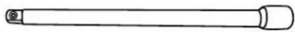
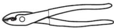
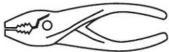
Tools Possibly Required (This Will Vary Depending On The Vehicle)
| Panel Removing Tool Sockets | Phillips Screwdriver | |
 |  | 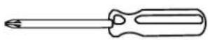 |
| Wire Cutters Extension Ratchet | ||
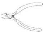 |  |  |
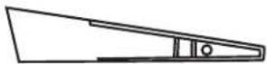
| Crimpers Pliers Torx Screwdriver | ||
 |  | 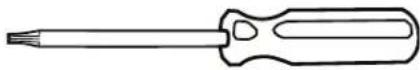 |
Accessory List
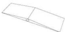
| Camera Bracket With HCE-C1100 Pre-assembled | Camera Extension Cable (7M/23FT) | Spare Tire Bracket |
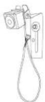 | 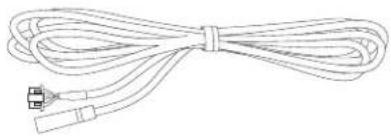 | 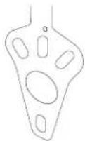 |
| Cable Ties x 5 Waterproofing Pad x 1 Power & Video Unit | ||
 |  | 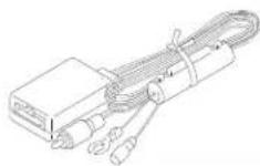 |
| Retaining Clips x 3 Waterproofing Pad Adhesive x 1 Quick Installation Guide x 1 | ||
 |  |  |
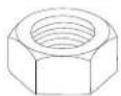
| Torx Screw & Lock Washer M6x8 x 1 | Torx Screw, Lock Washer, & Nut M6x12 x 1 | Nut For M6x12 Screw x 1 (Spare only, not used) |
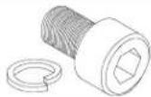 | 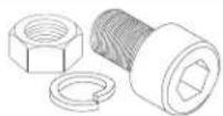 |  |
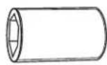
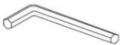
| Heat Shrink Tubing x 1 Allen Wrench x 1 | ||
 |  | |
Factory Unit Disassembly Process (2007-2010 Only)
⚠ Warning: Before you begin wiring, remove the ground wire from the negative terminal of the battery. Failing to do so can lead to electric shock, injury or damage to equipment.
DISCONNECT THE BATTERY BEFORE CONTINUING. FAILURE TO DO SO WILL DISABLE MANY FEATURES.
1 Remove top by releasing 2 rear clips on the back of the top panel and then pull panel forward.
3 Release 2 clips on the top of the bottom panel. This will expose two 7mm screws. Remove using a 7mm socket with ratchet & extension.
natural_image
Interior view of a vehicle dashboard with no visible text or symbols2 Release 2 clips on the top of the bottom panel. This will expose two 7mm screws. Remove those.
4 Use panel removal tool to remove dash panel by releasing 6 clips (3 per side)
natural_image
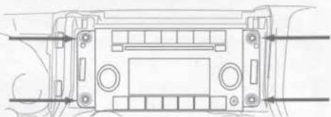
Technical line drawing of a mechanical assembly with no visible text or symbols5 Extract (4) 7 mm screws and remove the factory radio.
natural_image
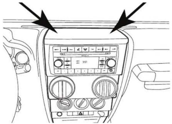
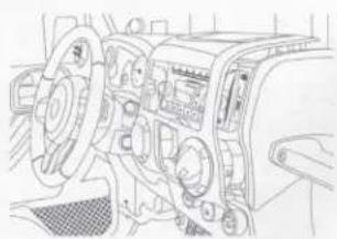
Technical line drawing of a vehicle front panel with directional arrows indicating movement or force (no text or symbols)Factory Unit Disassembly Process (2011-2018 Only)

DISCONNECT THE BATTERY BEFORE CONTINUING. FAILURE TO DO SO WILL DISABLE MANY FEATURES.
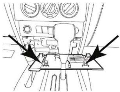
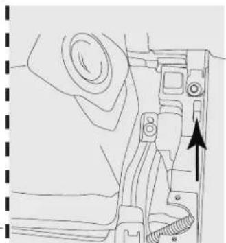
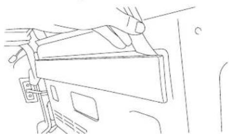
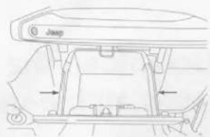
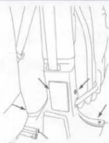
1 Remove the rubber cover from the top center storage area and extract (1) 7mm screw.
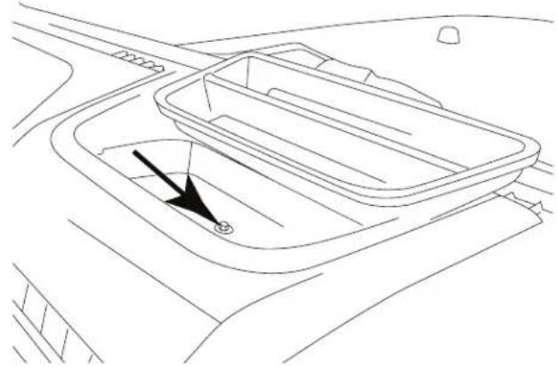
natural_image
Line drawing of a car interior showing a rectangular tray with a black arrow pointing to the center (no text or symbols)3 Remove the window switch pod using a panel removing tool and extract (1) 7mm screw.
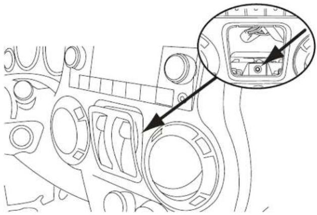
natural_image
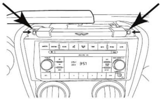
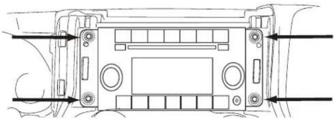
Technical line drawing of a mechanical component with an inset close-up showing internal components (no text or symbols)5 Extract (4) 7 mm screws and remove the factory radio.
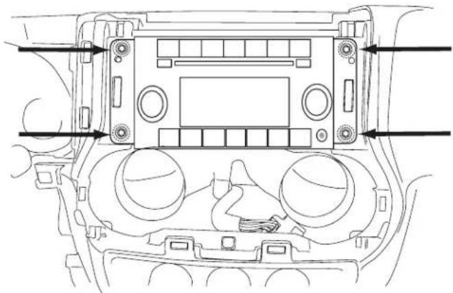
natural_image
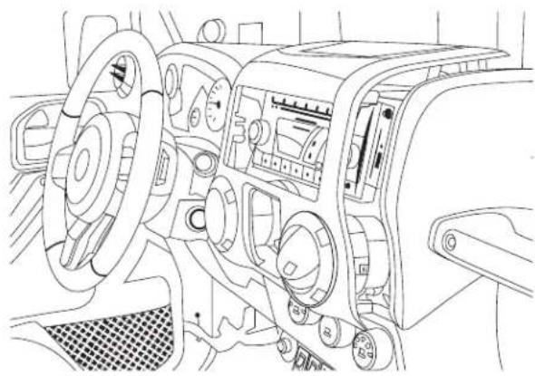
Technical line drawing of a vehicle dashboard with control panel and buttons (no text or symbols)2 Remove the knee cover panel and extract (2) 7mm screws located to the right and left sides of the steering wheel column.
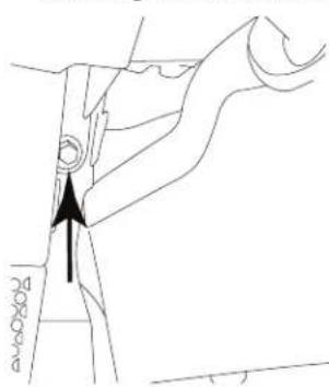
Left side of steering wheel column.
natural_image
Technical line drawing of a mechanical component with an arrow indicating direction (no text or symbols)Right side of steering wheel column.
4 Remove the dash panel.
natural_image
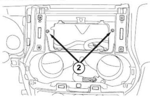
Interior view of a car dashboard and steering wheel (no text or symbols visible)6 Extract (2) 7 mm screws from the factory radio bracket and remove it.
Glove Box Removal
1 Open the glove box.
2 Push inwards both left and right sides to release the glove box out.
Removing B-Pillar Panel
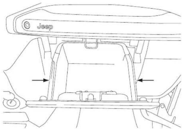
1 Remove B-Pillar panel by disengaging 4 clips on both front and rear passenger sides.
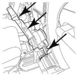
natural_image
Line drawing of a car seatbelt mechanism with arrows indicating movement or force (no text or symbols present)2 Using panel removing tool, unclip the B-Pillar. Be careful not to damage the panel.
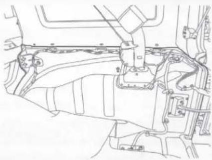
3 Lift the carpet up on both front and rear passenger sides to expose the OEM cables.
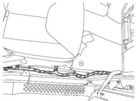
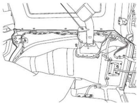
natural_image
Technical line drawing of a vehicle's front suspension system showing levers, drivetrain, and dashboard components (no text or labels)Removing Rear Right Side Panel
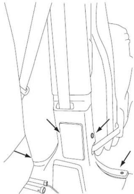
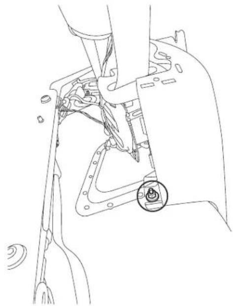
1 Using T25 Torx, remove the screws on the rear right side panel.
natural_image
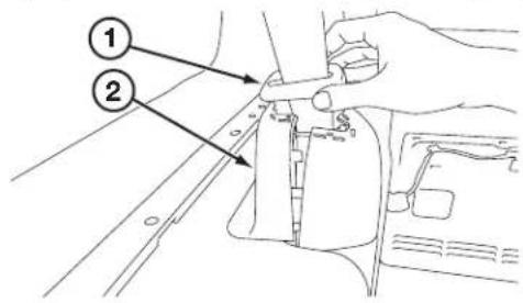
Line drawing of a car's seat and steering wheel assembly (no text or symbols)2 Using panel removing tools, pry off seatbelt cover[#1] and remove the roll cage cover[#2].
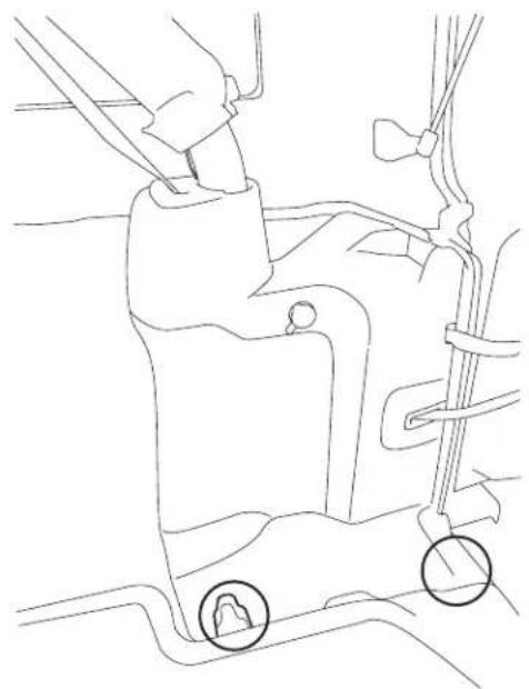
3 Using 10mm socket to remove the panel.
natural_image
Technical line drawing of a mechanical assembly with a highlighted component (no text or symbols)4 Unclip the cigarette lighter socket from the harness.
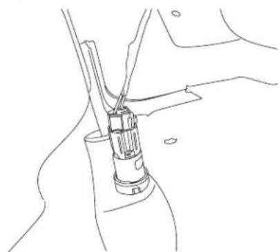
natural_image
Line drawing of a mechanical assembly with a tool inserted into a component (no text or symbols)5 Remove the Rear Right Side Panel.
natural_image
Technical line drawing of a mechanical assembly with no visible text or symbolsSpare Tire and Wheel Removal
1 Using 19mm socket, extract the lug nuts.
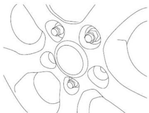
natural_image
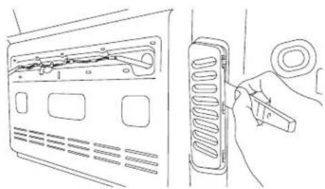
Abstract line drawing of interconnected curved shapes with no text or symbols3 Using panel removing tools, unclip and remove wire cover on the rear gate.
natural_image
Line drawing of a hand holding a device, no text or symbols present4 Using panel removing tools, unclip and remove vent cover on the rear gate.
natural_image
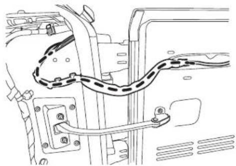
Line drawing showing a hand inserting a cable into a device panel (no text or symbols present)Camera & Light Extension Cable Installation
1 Route the wires:
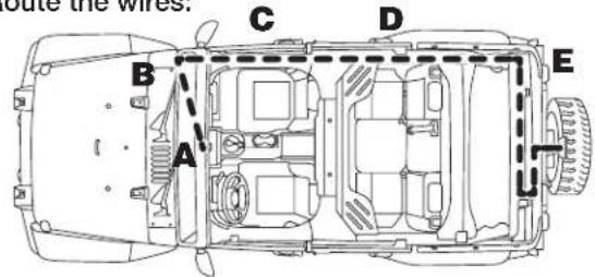
A. Start from the head unit harness
B. Behind the glove box
C. Down the passenger kick panel
D. Door sill
E. Along the rear right side panel
natural_image
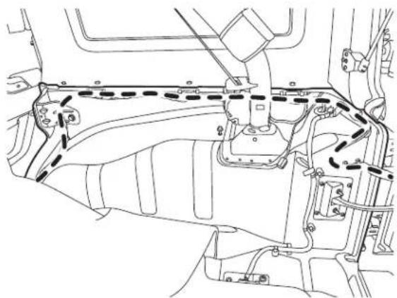
Technical line drawing of a vehicle engine compartment with no visible text or symbolsF. Along the rear door handle cable
natural_image
Technical line drawing of a vehicle's internal components, including suspension and wheel assembly (no text or labels)Camera & Light Extension Cable Installation
G. Secure to the factory cables.
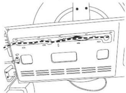
natural_image
Technical line drawing of a device rear panel with visible wiring and mounting holes (no text or symbols)H. Remove OEM grommet. Route the wire out of an OEM grommet hole. Insert the camera harness cable and the OEM third brake light cable through the rubber grommet provided. Cut rubber grommet by a razor blade if needed. Press the grommet firmly into the hole.
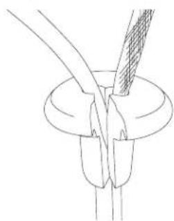
natural_image
Line drawing of a mechanical component with a curved tool inserted into a circular base (no text or symbols)I. Route along and through the centric hub.
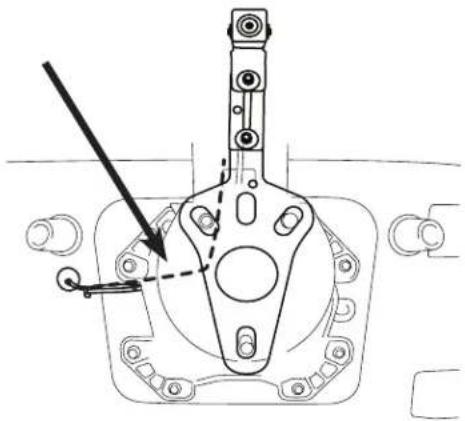
natural_image
Technical line drawing of a mechanical assembly with no visible text or symbolsRoute the cable so it does not interfere with any moving parts or safety equipment.
Use silicone to fill up all gaps around the grommet and cables to prevent water going into the rear gate.
⚠️ Failure to do so may cause moisture to go inside.
Bracket Installation
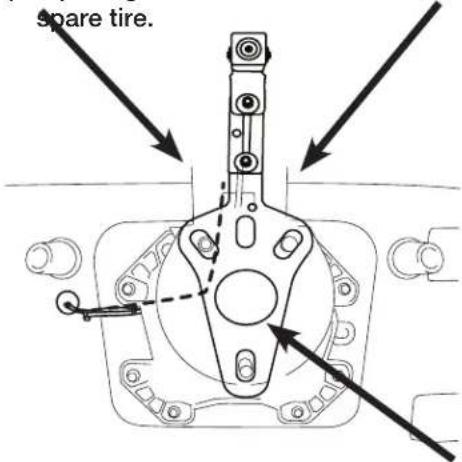
1) Attach camera bracket (which already uses the M6x8 & Lock Washer pre-assembled) to spare tire bracket using the supplied allen wrench, M6x12 torx screw, lock washer, and nut.
2) Adjust the bracket for the camera height.
3) Place bracket with camera over the studs and slide to the back. There's usually 2 on the top and 1 on the bottom.
4) Slide retaining clips over the studs to hold the bracket in place.
5) Check the spacing of the bracket by placing the spare tire back over the studs.
6) If spacing is correct use 19mm socket to re-install
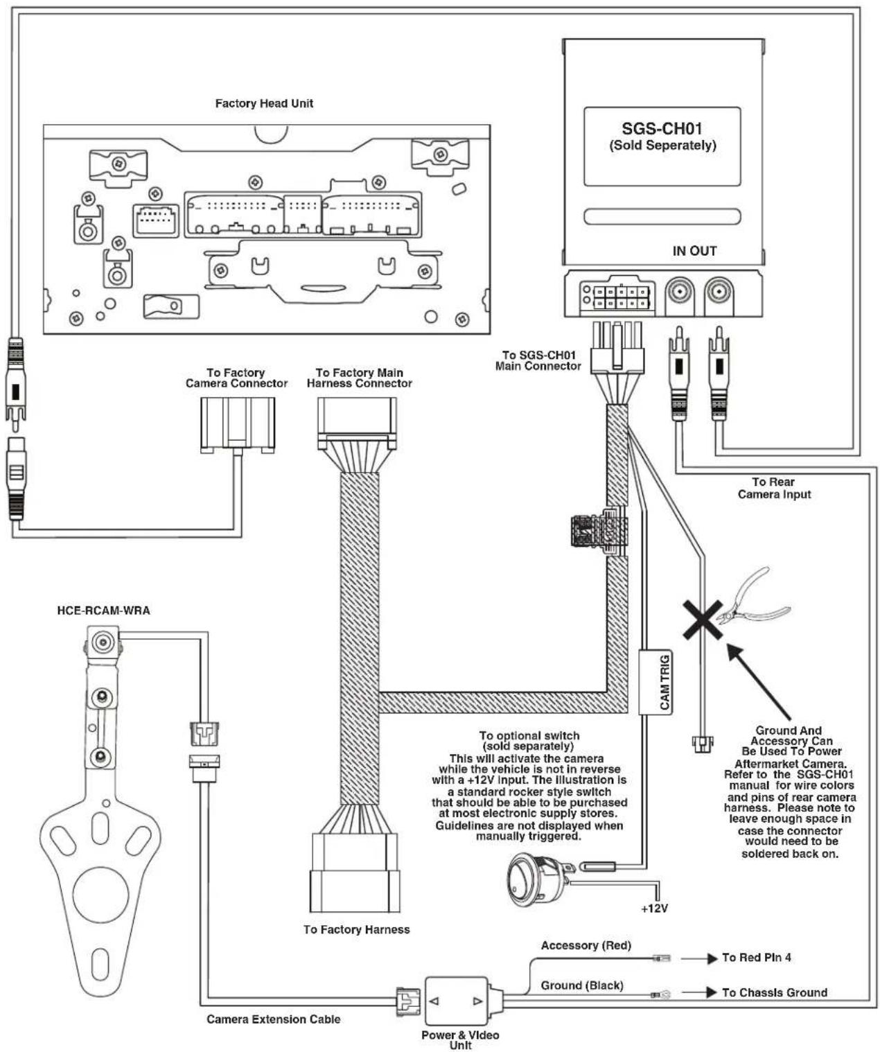
Wiring Diagram: OEM Head Unit With SGS-CHO1 (Sold Separately)
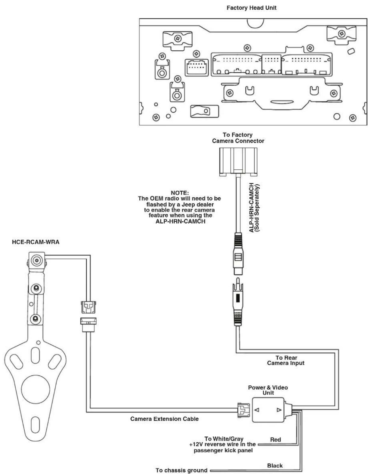
Wiring Diagram: OEM Head Unit With ALP-HRN-CAMCH (Sold Separately)
Wiring Diagram: Alpine Head Unit Using Direct Connection
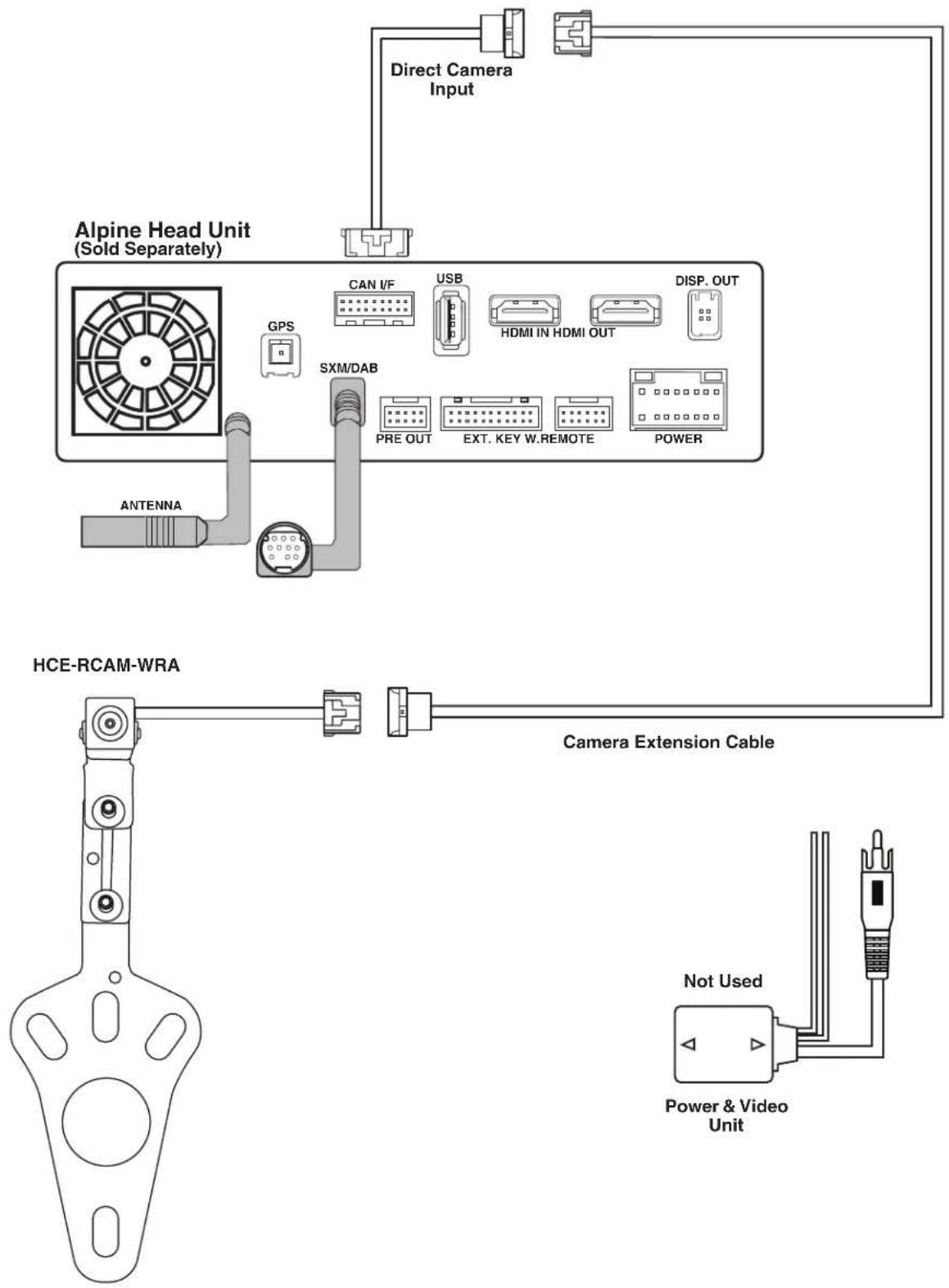
flowchart
graph TD
    A["Alpine Head Unit (Sold Separately)"] --> B["Direct Camera Input"]
    A --> C["HCE-RCAM-WRA"]
    C --> D["Camera Extension Cable"]
    D --> E["Power & Video Unit"]
    A --> F["GPS"]
    F --> G["SXM/DAB"]
    G --> H["PRE OUT"]
    G --> I["EXT. KEY W.REMOTE"]
    G --> J["POWER"]
    A --> K["CAN I/F"]
    K --> L["USB"]
    L --> M["HDMI IN HDMI OUT"]
    M --> N["DISP. OUT"]
Wiring Diagram: Alpine Head Unit With SGS-CHO1 (Sold Separately)
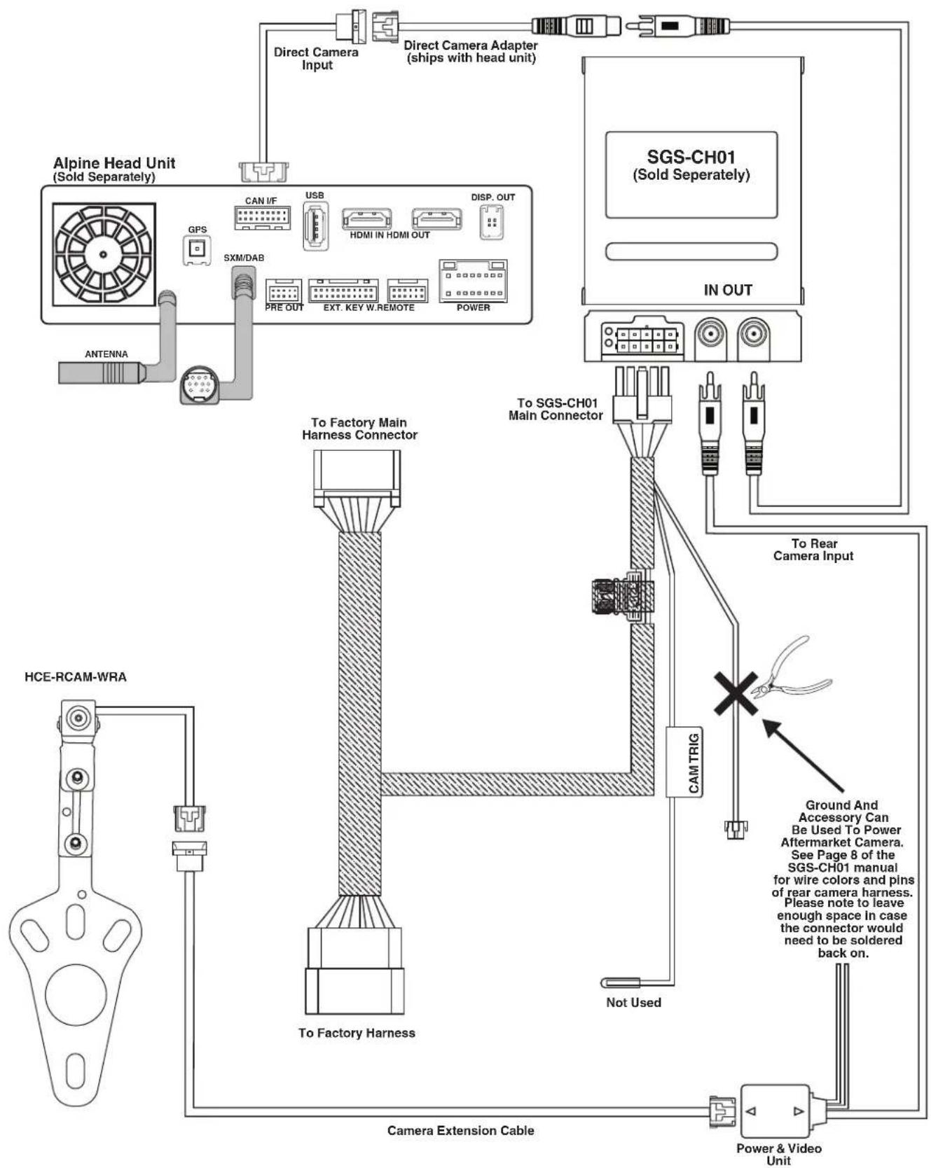
flowchart
graph TD
    A["Alpine Head Unit (Sold Separately)"] --> B["Direct Camera Input"]
    A --> C["Direct Camera Adapter (ships with head unit)"]
    A --> D["SGS-CH01 (Sold Separately)"]
    A --> E["IN OUT"]
    F["HCE-RCAM-WRA"] --> G["To Factory Harness"]
    G --> H["Camera Extension Cable"]
    I["ANTENNA"] --> J["GPS"]
    J --> K["SXM/DAB"]
    K --> L["PRE OUT"]
    K --> M["EXT. KEY W.REMOTE"]
    K --> N["POWER"]
    O["To Factory Main Harness Connector"] --> P["To SGS-CH01 Main Connector"]
    Q["Not Used"] --> R["Cam TRIG"]
    S["Ground And Accessory Can Be Used To Power Aftermarket Camera. See Page 8 of the SGS-CH01 manual for wire colors and pins of rear camera harness. Please note to leave enough space in case the connector would need to be soldered back on."] --> T["To Rear Camera Input"]
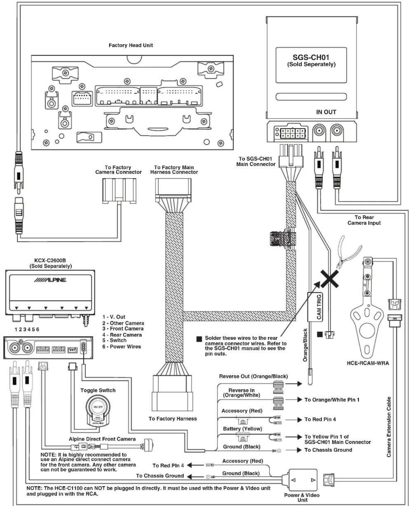
Wiring Diagram: OEM Head Unit With SGS-CH01 & KCX-C2600B (Sold Separately)
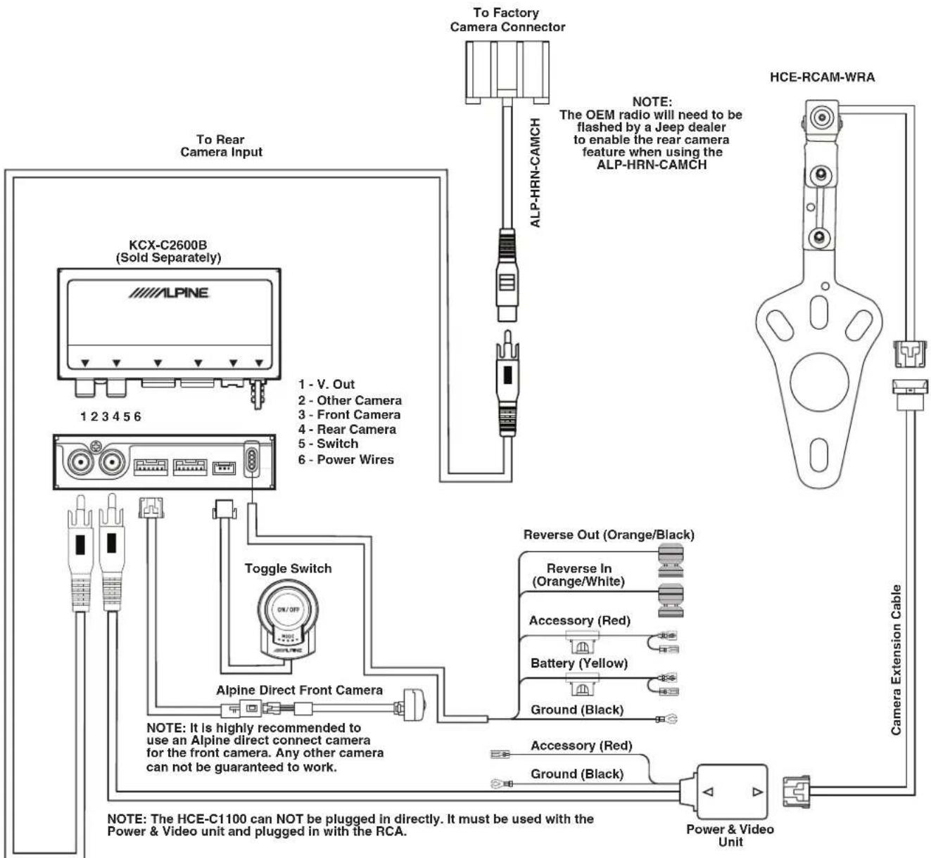
Wiring Diagram: OEM Head Unit With ALP-HRN-CAMCH & KCX-C2600B (Sold Separately)
Troubleshooting
| Symptom Possible Cause Remedy | |||
| 1 | Alpine head unit only shows guidelines in reverse. | The HCE-RCAM-WRA camera is not outputting a picture. | Check to make sure the camera is being powered on with a digital multimeter. |
| Test camera with a different display. Plug the RCA of the camera into a display with a RCA input. | |||
| Alternatively, you can use a different RCA source into the RCA input. For example, an old DVD player with a RCA output would show a picture with the vehicle in reverse. This will eliminate if the issue is with the head unit or the camera installation. | |||
| 2 | Nothing happens when vehicle is in reverse | The SGS-CH01 is not installed properly. | Refer to the SGS-CH01 installation manual and troubleshooting. |
| ALP-HRN-CAMCH was used and the dealership did not flash OEM radio. | Take vehicle to Jeep dealer and have them flash the OEM radio to turn on the rear camera input. | ||
| 3 | OEM radio not showing grid lines. | That's not a feature of the OEM radio. | The OEM radio does not generate grid lines. The camera does not have any kind of output for something like that. |
Jeep Wrangler
HCE-RCAM-WRA
Stealth-Mount Spare Tire Camera
Quick Installation Manual
● Model: Wrangler
● Model Year: 2007-2018
Jeep
natural_image
Line drawing of a classic off-road vehicle (no text or symbols)| Model | Year |
| Wrangler (JK) | 2007-2018 |
| Wrangler Unlimited (JK) | 2007-2018 |
* The specified vehicles have been tested and have met compatibility specs at the time of testing. Compatibility is not guaranteed if the manufacturer has made production changes to the listed vehicles above.

Warning: Before you begin wiring, remove the ground wire from the negative terminal of the battery. Failing to do so can lead to electric shock, injury or damage to equipment.
Installation Kit Parts
● Camera Bracket W/HCE-C1100 x 1
- Spare Tire Bracket x 1
● Camera Extension Cable x 1
● Quick Installation Manual x 1
● Power & Video Unit x 1
● Water Proofing Adhesive Pad x 1
● Water Proofing Pad x 1
● Cable Ties x 5
- Retaining Clips x 3
● Heat Shrink Tube x 1
● Torx Screw & Lock Washer x 1
● Allen Wrench x 1
Factory Unit Disassembly (2007-2010 Only)
1) Remove top by releasing 2 rear clips on the back of the top panel and then pull panel forward.
2) Release 2 clips on the top of the bottom panel. This will expose two 7mm screws. Remove those.
3) Release 2 clips on the top of the bottom panel. This will expose two 7mm screws. Remove using a 7mm socket with ratchet & extension.
4) Use panel removal tool to remove dash panel by releasing 6 clips (3 per side).
5) Extract (4) 7 mm screws and remove the factory radio.
natural_image
Technical line drawing of a vehicle dashboard with no visible text or symbolsFactory Unit Disassembly (2010-2018 Only)
1) Remove the rubber cover from the top center storage area and extract (1) 7mm screw.
2) Remove the knee cover panel and extract (2) 7mm screws located to the right and left sides of the steering wheel column.
3) Remove the window switch pod using a panel removing tool and extract (1) 7mm screw.
4) Remove the dash panel.
5) Extract (4) 7 mm screws and remove the factory radio.
6) Extract (2) 7 mm screws from the factory radio bracket and remove it.
natural_image
Line drawing of a vehicle dashboard with steering wheel and control panel (no text or symbols)Glove Box Removal
1) Open the glove box.
2) Push inwards both left and right sides to release the glove box out.
Remove B-Pillar Panel
1) Remove B-Pillar panel by disengaging 4 clips on both front and rear passenger sides.
2) Using panel removing tool, unclip the B-Pillar. Be careful not to damage the panel.
3) Lift the carpet up on both front and rear passenger sides to expose the OEM cables.
natural_image
Technical line drawing of a mechanical component with labeled parts (no text or symbols)Remove Right Side Panel
1) Using T25 Torx, remove the screws on the rear right side panel.
2) Using panel removing tools, pry off seatbelt cover and remove the roll cage cover.
3) Using 10mm socket to remove the panel.
4) Unclip the cigarette lighter socket from the harness.
5) Remove the Rear Right Side Panel.
natural_image
Technical line drawing of a vehicle chassis frame with structural components (no text or labels)Remove Spare Tire
1) Using 19mm socket, extract the lug nuts.
2) Using panel removing tools, unclip and remove wire cover on the rear gate.
Bracket Installation
1) Attach camera bracket to spare tire bracket using the supplied allen wrench, torx screw, and lock washer.
2) Adjust the bracket for the camera height.
3) Place bracket with camera over the studs and slide to the back. There's usually 2 on the top and 1 on the bottom.
4) Slide retaining clips over the studs to hold the bracket in place.
5) Check the spacing of the bracket by placing the spare tire back over the studs.
6) If spacing is correct use 19mm socket to re-install spare tire.
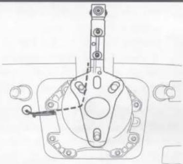
natural_image
Technical line drawing of a mechanical component with mounting holes and a central hub (no text or symbols)Route Extension Cable And Power & Video Unit
1) Route the wires starting at the head unit, to behind the glove box, down the passenger kick panel, along the door sill, through the right side panel area, and along the factory door handle cable.
2) Secure the cables.
3) Go through factory grommet.
4) Run cables to camera.
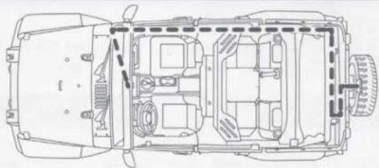
natural_image
Top-down technical line drawing of a car chassis showing internal compartments and structural elements (no text or labels)Download the full detailed version of the installation manual at www.alpine-usa.com/support.

- Jeep Wrangler HCE-RCAM-WRA Stealth-Mount Spare Tire Camera Installation Manual
- ⚠ Warning: Before you begin wiring, remove the ground wire from the negative terminal of the battery. Failing to do so can lead to electric shock, injury or damage to equipment.
- Introduction
- Note
- To Ensure Safe Use, Always Follow These Precautions
- Warning
- Caution
- Factory Unit Disassembly Process (2007-2010 Only)
- Factory Unit Disassembly Process (2011-2018 Only)
- Glove Box Removal
- Removing B-Pillar Panel
- Removing Rear Right Side Panel
- Spare Tire and Wheel Removal
- Camera & Light Extension Cable Installation
- Bracket Installation
- Jeep Wrangler
- HCE-RCAM-WRA
- Stealth-Mount Spare Tire Camera
- Quick Installation Manual
- Installation Kit Parts
- Factory Unit Disassembly (2007-2010 Only)
- Factory Unit Disassembly (2010-2018 Only)
- Remove B-Pillar Panel
- Remove Right Side Panel
- Remove Spare Tire
- Route Extension Cable And Power & Video Unit
Brand : ALPINE
Model : HCE-RCAM-WRA
Category : Rear Camera