
HCE-TCAM1-WRA - Rear Camera ALPINE - Free user manual and instructions
Find the device manual for free HCE-TCAM1-WRA ALPINE in PDF.

| Product Type | Spare Tire Camera & Light System |
| Model | HCE-TCAM1-WRA |
| Brand | Alpine |
| Compatible Vehicles | Jeep Wrangler / Wrangler Unlimited (2007-Up), all trims |
| Power Requirements | 9V - 16V DC, negative ground |
| Power Consumption | Less than 0.7W |
| Output Image | Mirror image, VBS (NTSC color signal system) |
| Image Sensor | 1/4 type color CMOS, 640 x 480 pixels (approx. 300,000 pixels), aspect ratio 4:3 |
| Lens | Focal length: f=1.28mm, brightness: F=2.4 |
| Field of View | Horizontal: 132°, Vertical: 105° |
| Illumination Range | Approx. 1.0 lx to 100,000 lx |
| Operating Temperature | -30°C to +70°C (-22°F to +158°F) |
| Storage Temperature | -40°C to +85°C (-40°F to +185°F) |
| Waterproof Rating | IP66 (dust-proof and waterproof rugged design) |
| Dimensions (Camera & Light Unit) | 180 x 180 x 52 mm (7.1 x 7.1 x 2 in) |
| Weight (Camera & Light Unit) | 770 g (1 lb 11 oz) |
| Package Weight | 1,960 g (4 lb 5 oz) |
| Features | Built-in brake and reverse lights, optimized camera angle for near/far objects, lug nut mounting, includes three mounting posts (short, mid, long) for wheel/tire depth |
| Included Accessories | Spare tire camera & light unit, mounting base, lug nut camera base, mounting posts (3), M4 hex socket cap screws (8), camera & light extension cable (7m), rubber grommet, camera & light T-harness, installation manual, warranty card, quick start guide |
| Warranty | 3 years (original purchaser, USA/Canada) |
Frequently Asked Questions - HCE-TCAM1-WRA ALPINE
User questions about HCE-TCAM1-WRA ALPINE
0 question about this device. Answer the ones you know or ask your own.
Ask a new question about this device
Download the instructions for your Rear Camera in PDF format for free! Find your manual HCE-TCAM1-WRA - ALPINE and take your electronic device back in hand. On this page are published all the documents necessary for the use of your device. HCE-TCAM1-WRA by ALPINE.
USER MANUAL HCE-TCAM1-WRA ALPINE
HCE-TCAM1-WRA Spare Tire Camera & Light System for Jeep Wrangler Installation Manual
● Model: Jeep Wrangler (JK)
● Model Year: 2007-UP
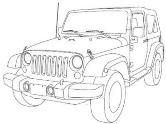
natural_image
Line drawing of a classic off-road vehicle (no text or symbols)* The specified vehicles have been tested and have met compatibility specifications at the time of testing. Compatibility is not guaranteed if the manufacturer has made production changes to the vehicles listed above.
Introductions
● Design and specifications are subject to change without notice for improvement.
To Ensure Safe Use, Always Follow These Precautions
● The installation of this product requires specialized skills and experience. We recommend that you have the product installed by an Alpine authorized dealer.
- Before you use this product, be sure to carefully read this installation manual and the separate user's manual so that you can use the product correctly. Alpine Electronics bears no responsibility for problems that arise as a result of failure to follow the instructions in the manuals.
● This manual includes a number of symbols that are intended to help you use the product safely, to prevent harm to you and others, and to protect against damage to property. These symbols and their meanings are listed below. Make sure you fully understand these symbols before you begin reading the main text.
Explanations of Injury and Damage That May Result from Incorrect Use
| [1474] Warning | Ignoring the content marked by this indication and using the product incorrectly is expected to lead to death or serious injury. |
 Caution Caution | Ignoring the content marked by this indication and using the product incorrectly is only expected to lead to injury or property damage. |
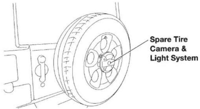
Spare Tire Camera & Light System for Jeep Wrangler
Warying
Types of Precautions
 Forbidden Forbidden | Indicates actions that are forbidden (must not be performed) |  Mandatory Mandatory | Indicates actions that are mandatory (must be performed) |
 Forbidden Forbidden | Indicates that disassembly is forbidden. |  | Marks content that should receive your full attention. |

Warning
Do not disassemble or modify the product. Doing so could lead to an accident, fire, or electric shock.

Forbidden
Store screws and other small objects where small children cannot reach them. If one of these small objects is swallowed, consult with a doctor immediately.

When replacing fuses, be sure to use fuses with the specified current rating. Failing to do so could lead to an accident or fi re.

Forbidden

Mandatory
Only connect the product to a 12 VDC negative ground car. Failing to do so could lead to an accident or fire.

Mandatory
Before you begin wiring, remove the ground wire from the negative terminal of the battery. Failing to do so could lead to electric shock or injury.

Do not cut the insulation on a cord and take power from another device. Doing so could lead to fire or electric shock.

Forbidden
Do not install the product in a location where it will obstruct the driver's forward view; interfere with the operation of the steering wheel, gearshift, or the like; or pose a threat to passengers. Doing so could lead to an accident or injury.

Forbidden
Spare Tire Camera & Light System for Jeep Wrangler
Worbling
When making a hole in the vehicle body, be careful to avoid damaging pipes, the fuel tank, electrical wiring, and the like. This kind of damage could lead to an accident or fi re.

When installing and grounding the product, do not use any of the bolts or nuts of the steering wheel, brakes, fuel tank, or the like. Doing so could make the brakes stop working or lead to fi re.

Forbidden
Do not install the product near the passenger-side airbag. Doing so could interfere with the operation of the airbag and lead to an accident or injury.

Forbidden
Bundle cords so that they don't interfere with driving. Wrapping cords around the steering wheel, gearshift, brake pedal, or the like, could lead to an accident or damage equipment.

Caution
Connect the product properly according to the instructions. Failing to do so could lead to fi re or an accident.

Forbidden
Do not sandwich cords between the seat railing or allow them to touch protrusions. Resulting breaks or shorts could lead to electric shock or fire.

Do not block vents or heat sinks. Doing so could lead to fire or damage equipment.

Use the accessories according to the instructions, and attach them securely. Failing to do so could lead to an accident or damage equipment.

Forbidden
Do not install the product where it may be exposed to water or in a place with high levels of humidity or dust. Doing so could lead to fire or damage equipment.

Forbidden
The installation and wiring of this product requires specialized skills and experience. Have the product installed and wired by an authorized Alpine dealer.

Spare Tire Camera & Light System for Jeep Wrangler
Installation Kit Parts
Accessory List
| Spare Tire Camera & Light Unit Mounting Base Lug Nut Camera Base | ||
 |  |  |
| Mounting Posts (Short, Mid, Long) | M4 Hex Socket Cap Screws (8pcs) | Camera & Light Extension Cable (7m) |
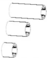 | 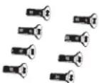 | 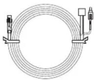 |
| Rubber Grommet Installation Manual Warranty Card and Quick Start Guide | ||
 |  |  |
| Camera & Light T-Harness | ||
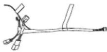 | ||
Spare Tire Camera & Light System for Jeep Wrangler
5/14
Tools Required
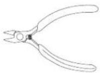
| Panel Removing Tool Pliers T25 Torx | ||
 |  |  |
| #2 Phillips Screwdriver Wire Cutters Torque Wrench | ||
 |  | 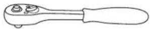 |
| 10 mm Sockets Socket Extension 19 mm Deep Socket | ||
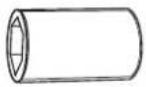 | 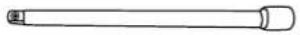 |  |
Spare Tire Camera & Light System for Jeep Wrangler
SpaceTire Camera and Light Installation
Glove Box Removal
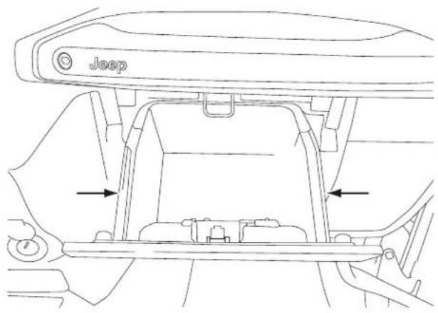
1 Open the glove box.
2 Push inwards both left and right sides to release the glove box out.
Removing B-Pillar Panel
1 Remove B-Pillar panel by disengaging 4 clips on both front and rear passenger sides.
natural_image
Line drawing of a car seatbelt mechanism with arrows indicating movement or force points (no text or symbols present)2 Using panel removing tool, unclip the B-Pillar. Be careful not to damage the panel.
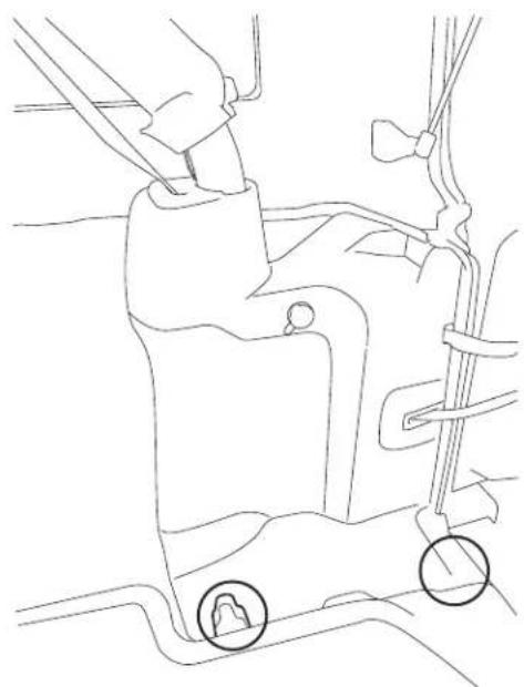
3 Lift the carpet up on both front and rear passenger sides to expose the OEM cables.
natural_image
Technical line drawing of a vehicle's front suspension system showing structural components (no text or labels)Spare Tire Camera & Light System for Jeep Wrangler
Spa7¢T4re Camera and Light Installation
Removing Rear Right Side Panel
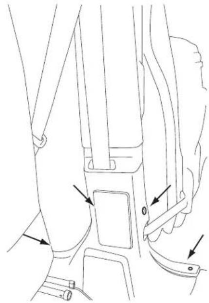
1 Using T25 Torx, remove the screws on the rear right side panel.
natural_image
Line drawing of a car's seat and steering wheel (no text or symbols)2 Using panel removing tools, pry off seatbelt cover[#1] and remove the roll cage cover[#2].
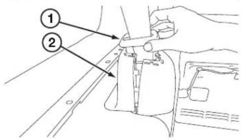
3 Using 10mm socket to remove the panel.
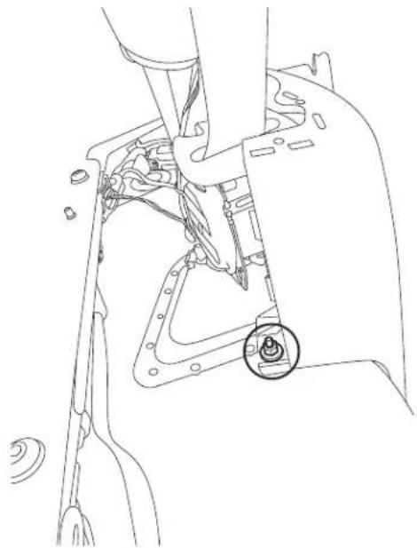
natural_image
Technical line drawing of a mechanical assembly with a highlighted circular component (no text or symbols)4 Unclip the cigarette lighter socket from the harness.
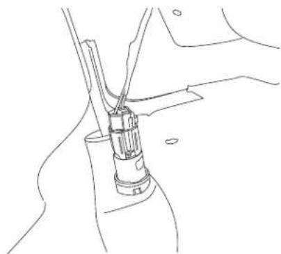
natural_image
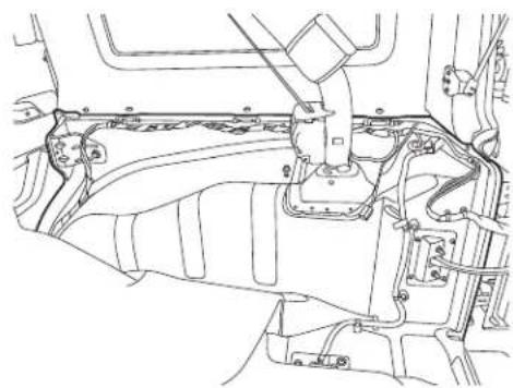
Line drawing of a mechanical joint or connector assembly (no text or symbols)5 Remove the Rear Right Side Panel.
natural_image
Technical line drawing of a vehicle engine compartment showing structural components (no text or labels)Spare Tire Camera & Light System for Jeep Wrangler
SpaceTire Camera and Light Installation
Spare Tire and Wheel Removal
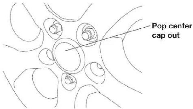
1 Using 19mm socket, extract the lug nuts.
2 Remove the spare tire center cap.
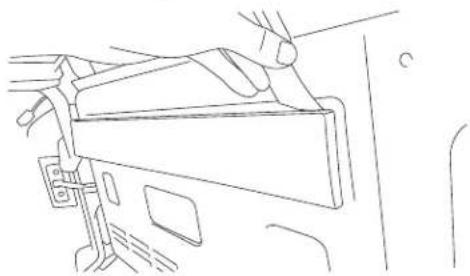
3 Using panel removing tools, unclip and remove wire cover on the rear gate.
natural_image
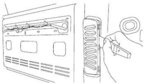
Line drawing of a hand inserting a device into a car compartment (no text or symbols)4 Using panel removing tools, unclip and remove vent cover on the rear gate.
natural_image
Line drawing of a device with a switch and attached spring-loaded component (no text or symbols)Camera & Light Extension Cable Installation
1 Connect RCA from the Camera & Light Extension Cable to the AUX input of the headunit.

| Connection Type Connectable Head Unit | ||
| A | Direct Connection | X109-WRA |
| B | Using Camera T-Harness Connection | i109-WRA |
| X009-WRA | ||
| Other iDatalink capable Alpine HU (X008U, X108U, INE-W957HD, INE-W967HD) | ||
| C | Cutting Camera T-Harness for Manual Connection | All other HU or display devices |
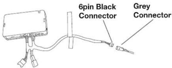
- Connection Type A - If connecting to Alpine X109-WRA, connect 6pin black connector on X109-WRA main harness to gray connector on the Camera & Light Extension Cable. (See page 14 in detail)
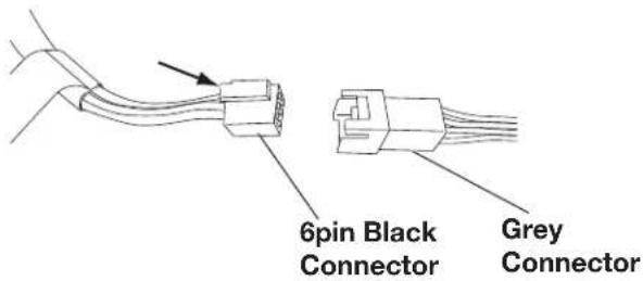
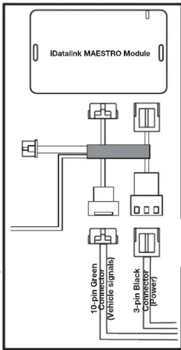
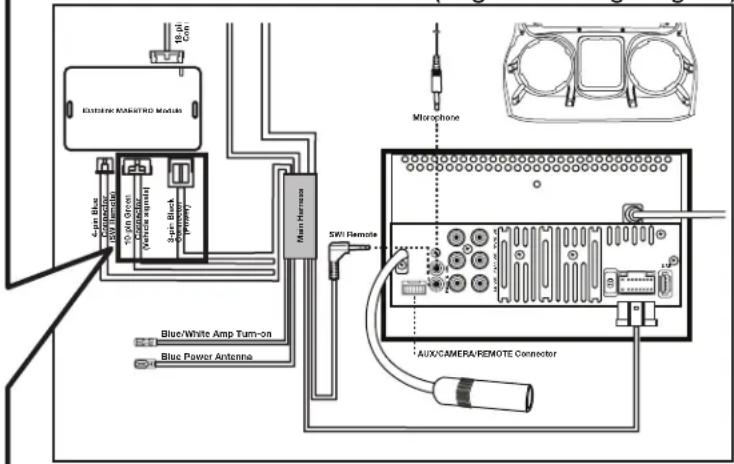
- Connection Type B - If connecting to iDatalink capable Alpine HU, use Camera & Light T-Harness to iDatalink Maestro Module and connect 6pin black connector to gray connector on the Camera & Light Extension Cable. (See page 14 in detail)
To i109-WRA and X009-WRA harness or Aftermarket iDatalink harnesses (sold separately)
Spare Tire Camera & Light System for Jeep Wrangler
Space Tire Camera and Light Installation
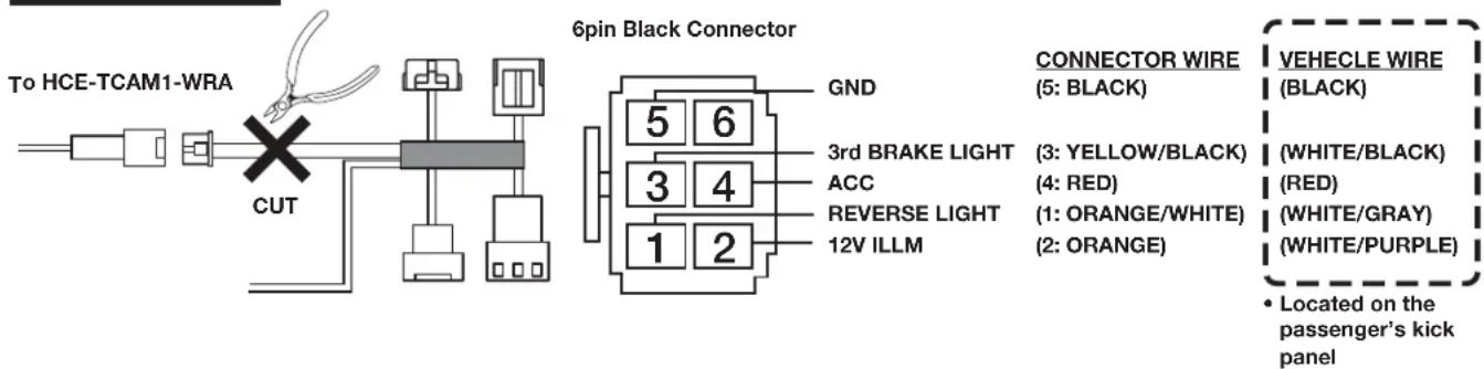
- Connection Type C -
If connecting to all other HU, cut Camera & Light T-Harness and manually connect to each wire located on the passenger's kick panel, then connect 6pin black connector to gray connector on the Camera & Light Extension Cable. (See page 14 in detail)

Connect ACC and GND properly according to the wiring diagram in page 14. Fail to do so could damage the product.
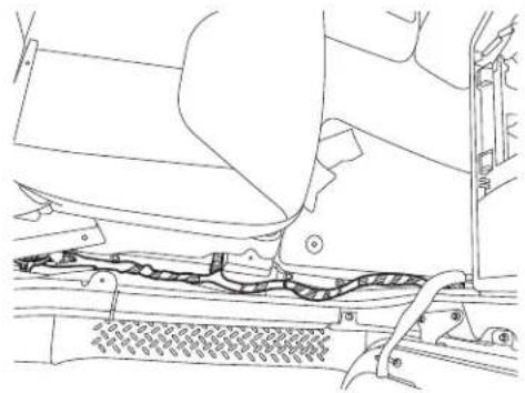
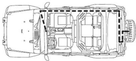
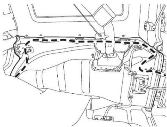
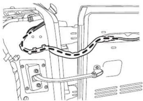
2 Route the wires:
natural_image
Technical line drawing of a car interior frame with no visible text or symbolsA. Start from the head unit harness
B. Behind the glove box
C. Down the passenger kick panel
D. Door sill
E. Along the rear right side panel
natural_image
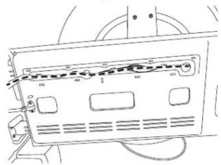
Technical line drawing of a mechanical assembly with no visible text or symbolsF. Along the rear door handle cable
natural_image
Technical line drawing of a vehicle's internal components, including suspension and wiring (no text or symbols)G. Secure to the factory cables.
natural_image
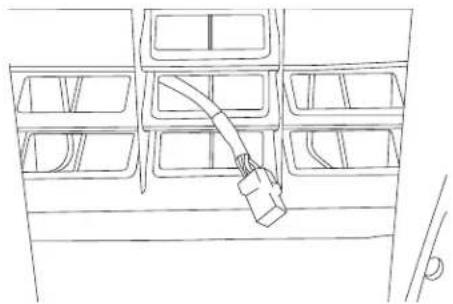
Line drawing of a device rear panel with ventilation slots and wiring (no text or symbols)OPTION 1:
H. Remove OEM grommet. Route the wire out of an OEM grommet hole. Insert the camera harness cable and the OEM third brake light cable through the rubber grommet provided. Cut rubber grommet by a razor blade if needed.
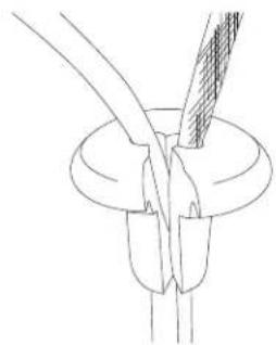
natural_image
Pure technical line drawing of a mechanical component with no text or symbolsI. Press the grommet firmly into the hole.

Use silicone to fi ll up all gaps around the grommet and cables to prevent water going into the rear gate.

Failure to do so may cause moisture to go inside.
J. Along and through the centric hub.
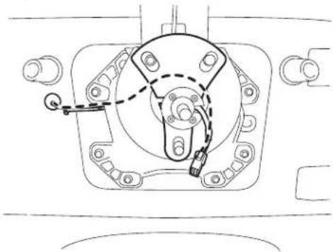
natural_image
Technical line drawing of a mechanical assembly with no visible text or symbols
Route the cable so it does not interfere with any moving parts or safety equipment.
Spare Tire Camera & Light System for Jeep Wrangler
Space/Flue Camera and Light Installation
OPTION 2:
H. Route the wire out of a rear gate vent behind tire carrier.
natural_image
Line drawing of a vehicle battery pack with a cable inserted into the rear compartment (no text or symbols)I. Along and through the centric hub.
natural_image
Technical line drawing of a mechanical component with mounting holes and a handle (no text or symbols)Spare Tire Camera & Light System for Jeep Wrangler
Spate/Pre Camera and Light Installation
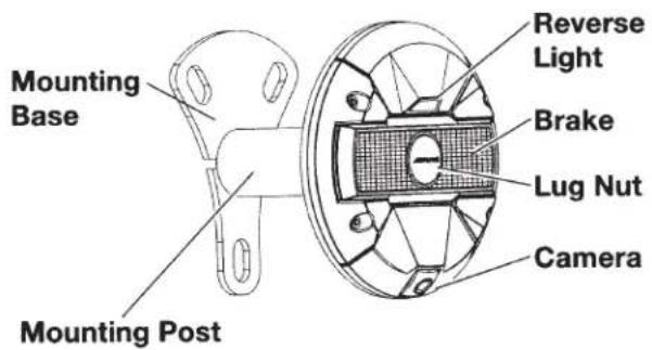
Spare Tire Camera & Light Unit Installation
1 Choose the length of the mounting post (Short, Mid, Long) based on your wheel depth and offset in order to see entire camera view.
| DEEP MID SHALLOW | |||
| WHEEL TYPE | 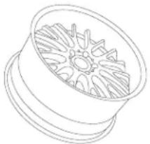 | 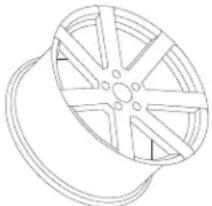 | 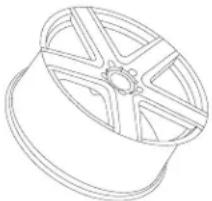 |
| CROSS SECTION | 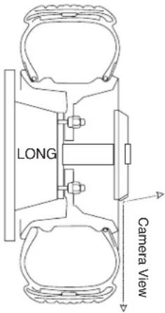 | 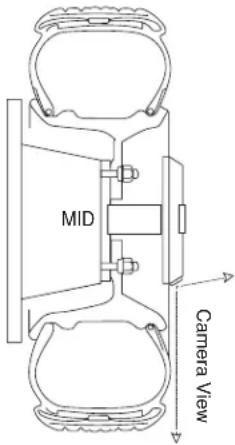 | 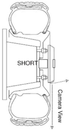 |
| Do not block downward view by wheel or tire. | |||
| Post Type Long Mid Short | |||
| Length | 4-1/4 inch (108.0mm) 3.0 | inch (76.2mm) 1-3/4 inch (44.4mm) | |
| Diameter 1-3/4 inch (44.4mm) | 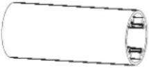 | 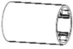 |  |
Spare Tire Camera & Light System for Jeep Wrangler
12/14
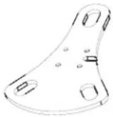
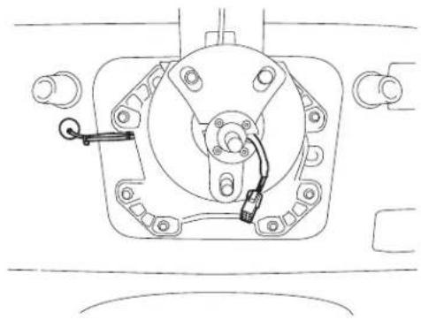
2 Using M4 hex key, assemble the lug nut camera base, mounting post, mounting base with the harness running along the cutout and inside the post.
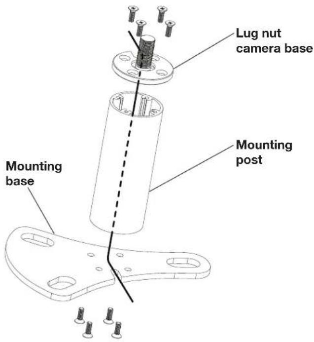
3 Position the mounting base assembly over the factory lug nuts. Ensure that no wires are pinched or interfered with any parts or safety equipment.
natural_image
Technical line drawing of a mechanical assembly with no visible text or symbols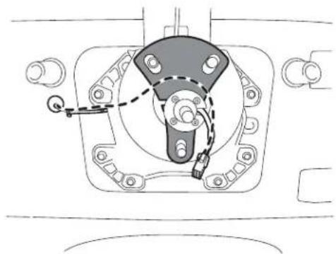
natural_image
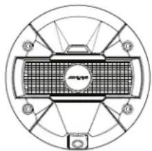
Technical line drawing of a mechanical assembly with no visible text or symbols4 Mount the spare tire back on the hub. Make sure the mount is aligned correctly and connector coming out of the center cap hole. Secure the spare tire by tightening all lug nuts.
natural_image
Top-down schematic of a car wheel assembly with six blades and central hub (no text or labels)
| Description | Torque Spec. (Ft. Labs.) |
| Spare Tire Carrier Lug Nut (Aluminum Wheel) | 54 |
| Spare Tire Carrier Lug Nut (Steel Wheel) | 72 |
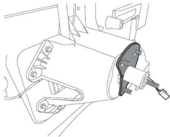
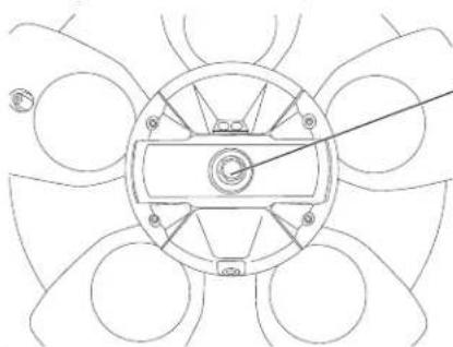
5 Connect the Spare Tire Camera and Light unit.
natural_image
Line drawing of a hand holding a cable or connector attached to a mechanical component (no text or symbols)
Do not drop Spare Tire Camera & Light unit on hard surface. Doing so could damage the unit.

Place floor mat or carpet on the ground underneath the camera to protect Spare Tire Camera & Light unit from dropping.
6 Press the connector into the slot. Use the rubber clips on the unit to secure the cable.
natural_image
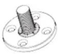
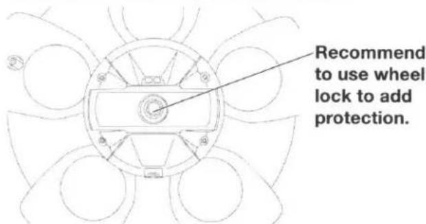
Mechanical assembly diagram showing a gear and shaft assembly with no visible text or symbols7 Using wheel lock, tighten the Spare Tire Camera and Light unit on the mount. Use threads on the unit to adjust horizontal angle of the camera.
natural_image
Pure mechanical diagram of a circular component with radial arms and central hub, no text or symbols presentRecommend to use wheel lock to add protection.

We recommend using a wheel lock to protect your investment.

| Description | Torque Spec. (Ft. Labs.) |
| Spare Tire Camera and Light Wheel Lock Lug Nut | 14 |
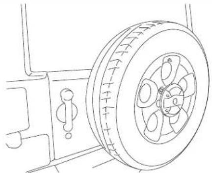
Completed Installation Image
natural_image
Line drawing of a car tire mounted on a vehicle (no text or symbols)
Before replacing spare tire, place floor mat or carpet on the ground underneath the camera to protect Spare Tire Camera & Light unit from dropping.

Do not drop Spare Tire Camera & Light unit on hard surface. Doing so could damage the unit.
1 Reinstall all panels, covers, carpets, cigarette lighter socket, and glove box as it was taken out.
2 Reinstall the ground battery cable to the battery negative post and torque the nut to the manufacturer's specification. Reinstall the metal brace.
Final Clean-Up
1 Clean up the interior of the vehicle so there are no materials, metal shavings, wire pieces, debris left in the vehicle.
2 Make a fi nal vehicle inspection to ensure everything has been properly installed and reconnected to the manufacturer's specifications.
Spare Tire Camera & Light System for Jeep Wrangler
● 14/14
Wiring Diagram
Connection Type A Direct Connection
(Refer to X109-WRA Installation Manual Page 11: Wiring Diagram)
To HCE-TCAM1-WRA
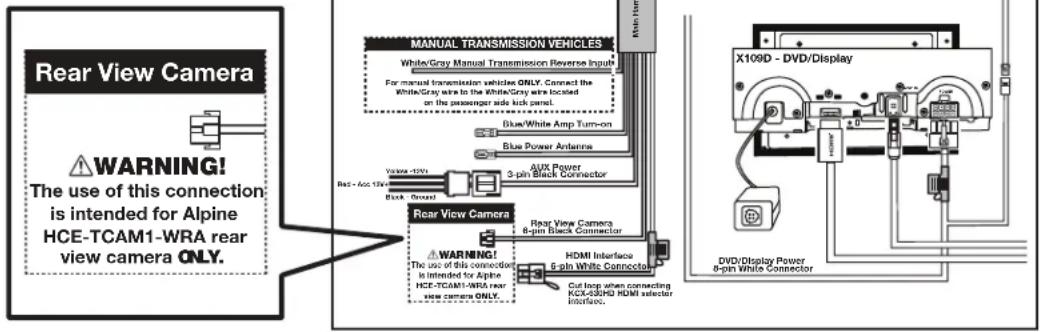
Connection Type B Using Camera T-Harness Connection
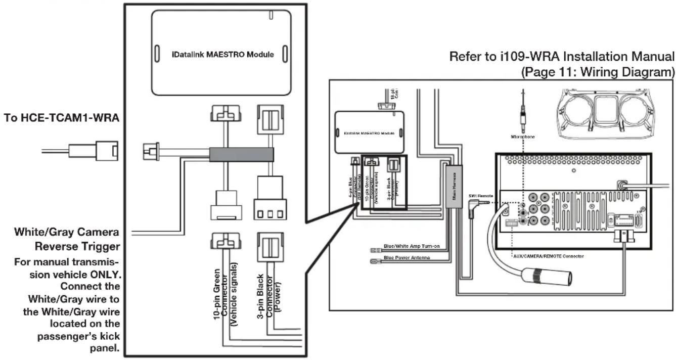
Connection Type C Cutting Camera T-Harness for Manual Connection
ALPINE®
SPARE TIRE CAMERA & LIGHT SYSTEM
HCE-TCAM1-WRA
QUICK REFERENCE GUIDE
Please read before using this equipment.
GUIDE DE RÉFÉRENCE RAPIDE
Torrance, California 90501 U.S.A.
Tel.: 1-800-ALPINE-1 (1-800-257-4631)
ALPINE ELECTRONICS (BENELUX) GmbH
Leuvensesteenweg 510-B6,
1930 Zaventem, Belgium
Tel.: 02-725 1315
ALPINE ELECTRONICS OF AUSTRALIA PTY, LTD.
161-165 Princess Highway, Hallam
Victoria 3803, Australia
Tel.: 03-8787-1200
ALPINE ELECTRONICS GmbH
Fletchamstead Highway, Coventry
CCV4 9TW, U.K.
Tel.: 0870-33 33 763
ALPINE ELECTRONICS FRANCE S.A.R.L.
(RCS PONTOISE B 338 101 280)
98, Rue de la Belle Etoile, Z.I. Paris Nord II,
B.P. 50016, 95945 Roissy Charles de Gaulle
Cedex, France
Tel.: 01-48638989
Designed by Alpine Electronics of America, Inc.
Printed In China

WARNING
This symbol means important instructions. Failure to heed them can result in serious injury or death.
WHEN USING A CAMERA SYSTEM, THE DRIVER MUST VISUALLY CHECK ACTUAL CONDITIONS AROUND THE VEHICLE. MAKE SURE THERE ARE NO PERSONS OR ANIMALS IN THE AREA IN WHICH YOU ARE MANOEUVRING OTHERWISE YOU COULD INJURE THEM.
A camera assists the driver by sending images to the screen showing conditions in view of the camera. The camera uses a wide-angle lens. Therefore, there is a difference in distance perspective between what is normally seen and what appears on the screen. Also, the images shown by the rearview camera are reversed, so as to appear the same as what is seen through the rearview mirror.
The camera may not perform to full capability due to variables such as:
- weather conditions such as hard rain, snow, fog or mud
• extremely high or low temperatures near camera
• slope of vehicle and/or roadway - direct exposure to very bright light such as headlamp or bright sunlight
- moving from very dark to very bright light and vice versa such as in parking garages or tunnels
• extremely low light areas - walls or objects that are located diagonally in relation to the camera
• changes to height of vehicle due to loading capacity or hydraulic suspensions
• obstacles located at the corner of the vehicle
DO NOT DISASSEMBLE OR ALTER.
Doing so may result in an accident, fire or electric shock.
KEEP SMALL OBJECTS SUCH AS BOLTS OR SCREWS OUT OF THE REACH OF CHILDREN.
Swallowing them may result in serious injury. If swallowed, consult a Doctor immediately.
MINIMISE DISPLAY VIEWING WHILE DRIVING.
Viewing the display may distract the driver from looking ahead of the vehicle and cause an accident.
CHECK THAT THE CAMERA MOUNTINGS IS ATTACHED SECURELY, AND THAT THE SCREWS ARE TIGHT BEFORE DRIVING.
Failure to do so may result in an accident.
WHEN INSTALLING OR CHECKING A CAMERA, DO SO AFTER PARKING THE CAR IN A LEVEL, SAFE PLACE, TURNING OFF THE ENGINE, AND APPLYING THE HAND BRAKE.
Failure to do so may result in an accident.

CAUTION
This symbol means important instructions. Failure to heed them can result in injury or material property damage.
HALT USE IMMEDIATELY IF A PROBLEM APPEARS.
Failure to do so may cause personal injury or damage to the product. Return it to your authorized Alpine dealer or the nearest Alpine Service Center for repairing.
NOTICE
- About Care of Device
- To prevent the camera lens, mounting and cords from changing color or shape, or from deteriorating, wipe with a chemicalfree, damp cloth.
- About Rear Camera
The rear camera is optimized for use in this system. as a dedicated product, it should not be used in other systems.
Spare Tire Camera & Light System for Jeep Wrangler (2007-UP)
Product Summary /Spare Tire Replace Instructions
Product Summary
Compatible Vehicle
■ Make: Jeep
■ Model: Wrangler / Wrangler Unlimited
■ Model Year: 2007 - UP
- Trim Level: All trim levels
Product Feature
- Compatible with most Aftermarket and OEM wheels using spare tire mount
- Works with Aftermarket or OEM in-dash display
■ Waterproof and dust-proof rugged design camera system (IP66)
■ Built-in Brake and Reverse lights for increased visibility - Optimized camera angle for near and far objects
- Lug nut mounting for easy removal and wheel locking
- 3 mounting posts included for wheel/tire depth
Product Specifications
Power Requirements......9V - 16V DC
Ground Type ...... Negative ground type
Power Consumption.....less than 0.7W
Output Image......Mirror image, VBS (NTSC Color signal system)
Output Drive Capacity......75 ohms
Image Sensor....1/4 type color CMOS image sensor, aspect ratio 4 : 3
Effective Number of Pixels..640 (horizontal) x 480 (vertical) approximately 300,000 pixels
Lens Section....Focal length: f=1.28mm, brightness: F=2.4
Field of View .... Horizontal: 132°, Vertical: 105°
Automatic Image ....Automatic metering
Adjusting Function adjustment, Automatic white balance adjustment
Synchro-System .......Internal synchronization
S/N ratio......46dB or more
Resolution....300 TV lines (horizontal, center area)
Illumination Range.....Approx. 1.0 lx to 100,000 lx
Operating....-30°C to +70°C
Temperature Range (-22°F to +158°F)
Storage Temperature Range... -40°C to +85°C (-40°F to +185°F)
External Dimensions (W x H x D)
Camera & Light.....180 x 180 x 52 mm
Unit only (7.1 x 7.1 x 2 inch)
Package 205 x 205 x 168 mm (8.1 x 8.1 x 6.6 inch)
Weight
Camera & Light......770g (1lb 11oz)
Unit only
Package (All included)..... 1,960g (4lb 5oz)
Spare Tire Camera & Light System for Jeep Wrangler (2007-UP)
Completed Installation Image /Product Specifications
● 4/12
Spare Tire Replace Instructions

CAUTION
Need extra careful when you replace the spare tire.
- Do not drop Spare Tire Camera & Light unit on hard surface. Doing so could damage the unit.
- Do not place wheel on the mounting post.
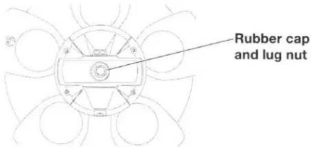
Removing the Spare Tire
1 Remove rubber cap and lug nut.
2 Remove the Spare Tire Camera & Light unit and unplug the connector.
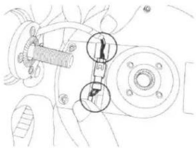
natural_image
Technical line drawing of a mechanical assembly with no visible text or symbols3 Remove the spare tire.
natural_image
Technical line drawing of a mechanical assembly with no visible text or symbolsInstalling the Spare Tire
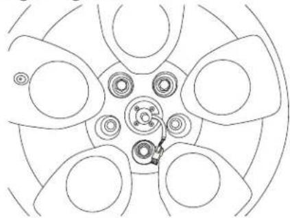
1 Mount the spare tire back on the hub. Make sure the mount is aligned correctly and connector coming out of the center cap hole. Secure the spare tire by tightening all lug nuts.
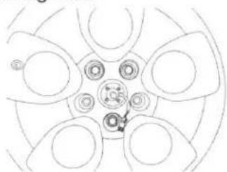
natural_image
Top-down schematic of a car wheel rim with no text or symbols
| Description | Torque Spec. (ft-lbs) |
| Spare Tire Carrier Lug Nut (Aluminum Wheel) | 54 |
| Spare Tire Carrier Lug Nut (Steel Wheel) | 72 |
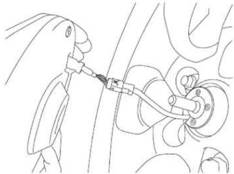
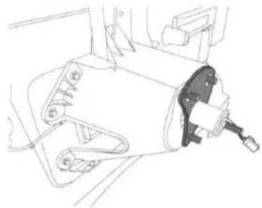
2 Connect the Spare Tire Camera and Light unit.
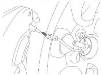
natural_image
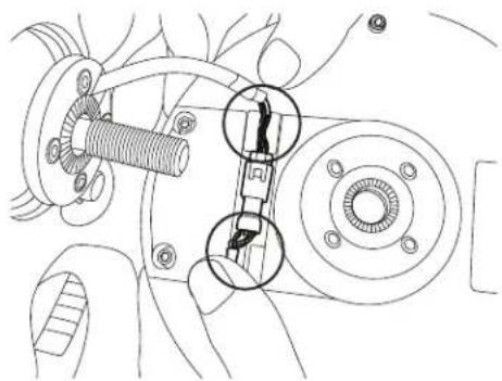
Line drawing of a mechanical assembly with a tool inserted into a component (no text or symbols)3 Press the connector into the slot. Use the rubber clips on the unit to secure the cable.

natural_image
Technical line drawing of a mechanical assembly with numbered components (no text or symbols)4 Using wheel lock, tighten the Spare Tire Camera and Light unit on the mount. Use threads on the unit to adjust horizontal angle of the camera.
We recommend using a wheel lock to protect your investment.
| Description | Torque Spec. (ft-lbs) |
| Spare Tire Camera and Light Wheel Lock Lug Nut | 14 |
GARANTIE LIMITÉE
● PRODUITS COUVERTS PAR LA GARANTIE
● COMMENT SE PRÉVALOIR DE LA GARANTIE
● EXCLUSIONS DE LA GARANTIE
ALPINE STIPULE EXPRESSÉMENT QU'ELLE N'EST PAS RESPONSABLE DES DOMMAGES-INTÉRÊTS ET DOMMAGES INDIRECTS PROVOQUÉS PAR LE PRODUIT. LES DOMMAGES-INTÉRÊTS SONT LES FRAIS DE TRANSPORT DU PRODUIT VERS UN CENTRE DE SERVICE ALPINE, LA PERTE DE TEMPS DE L'ACHETEUR ORIGINAL, LA PERTE D'UTILISATION DU PRODUIT, LES BILLETS D'AUTOBUS, LA LOCATION DE VOITURES ET TOUS LES AUTRES FRAIS LIÉS À LA GARDE DU PRODUIT. LES DOMMAGES INDIRECTS SONT LES FRAIS DE RÉPARATION OU DE REMPLACEMENT D'AUTRES BIENS ENDOMMAGÉS SUITE AU MAUVAIS FONCTIONNEMENT DU PRODUIT. LES RECOURS PRÉVUS PAR LES PRÉSENTES EXCLUENT ET REMPLACENT TOUTE AUTRE FORME DE RECOURS.
● LIEN ENTRE LA GARANTIE ET LA LOI
● CLAUSE APPLICABLE AU CANADA SEULEMENT
ALPINE ELECTRONICS OF AMERICA, INC. ("Alpine"), is dedicated to quality craftsmanship and is pleased to offer this Warranty. We suggest that you read it thoroughly. Should you have any questions, please contact your Dealer or contact Alpine at one of the telephone numbers listed below.
● PRODUCTS COVERED:
This Warranty covers Car Audio Products and Related Accessories ("the product"). Products purchased in the Canada are covered only in the Canada. Products purchased in the U.S.A. are covered only in the U.S.A.
● LENGTH OF WARRANTY:
This Warranty is in effect for three years from the date of the first consumer purchase.
WHO IS COVERED:
This Warranty only covers the original purchaser of the product, who must reside in the United States, Puerto Rico or Canada.
WHAT IS COVERED:
This Warranty covers defects in materials or workmanship (parts and labor) in the product.
WHAT IS NOT COVERED:
This Warranty does not cover the following:
① Damage occurring during shipment of the product to Alpine for repair (claims must be presented to the carrier).
② Damage caused by accident or abuse, including burned voice coils caused by over-driving the speaker (amplifier level is turned up and driven into distortion or clipping). Speaker mechanical failure (e.g. punctures, tears or rips). Cracked or damaged LCD panels. Dropped or damaged hard drives.
③ Damage caused by negligence, misuse, improper operation or failure to follow instructions contained in the Owner's manual.
④ Damage caused by act of God, including without limitation, earthquake, fire, flood, storms or other acts of nature. Any cost or expense related to the removal or reinstallation of the product.
⑤ Service performed by an unauthorized person, company or association.
⑥ Any product which has the serial number defaced, altered or removed.
⑦ Any product which has been adjusted, altered or modified without Alpine's consent.
⑧ Any product not distributed by Alpine within the United States, Puerto Rico or Canada.
⑨ Any product not purchased from an Authorized Alpine Dealer.
● HOW TO OBTAIN WARRANTY SERVICE:
① You are responsible for delivery of the product to an Authorized Alpine Service Center or Alpine for repair and for payment of any initial shipping charges. Alpine will, at its option, repair or replace the product with a new or reconditioned product without charge. If the repairs are covered by the warranty, and if the product was shipped to an Authorized Alpine Service Center or Alpine, Alpine will pay the return shipping charges.
② You should provide a detailed description of the problem(s) for which service is required.
③ You must supply proof of your purchase of the product.
④ You must package the product securely to avoid damage during shipment. To prevent lost packages it is recommended to use a carrier that provides a tracking service.
● HOW WE LIMIT IMPLIED WARRANTIES:
ANY IMPLIED WARRANTIES INCLUDING FITNESS FOR USE AND MERCHANTABILITY ARE LIMITED IN DURATION TO THE PERIOD OF THE EXPRESS WARRANTY SET FORTH ABOVE AND NO PERSON IS AUTHORIZED TO ASSUME FOR ALPINE ANY OTHER LIABILITY IN CONNECTION WITH THE SALE OF THE PRODUCT.
● HOW WE EXCLUDE CERTAIN DAMAGES:
ALPINE EXPRESSLY DISCLAIMS LIABILITY FOR INCIDENTAL AND CONSEQUENTIAL DAMAGES CAUSED BY THE PRODUCT. THE TERM "INCIDENTAL DAMAGES" REFERS TO EXPENSES OF TRANSPORTING THE PRODUCT TO THE ALPINE SERVICE CENTER, LOSS OF THE ORIGINAL PURCHASER'S TIME, LOSS OF THE USE OF THE PRODUCT, BUS FARES, CAR RENTALS OR OTHERS COSTS RELATING TO THE CARE AND CUSTODY OF THE PRODUCT. THE TERM "CONSEQUENTIAL DAMAGES" REFERS TO THE COST OF REPAIRING OR REPLACING OTHER PROPERTY WHICH IS DAMAGED WHEN THIS PRODUCT DOES NOT WORK PROPERLY. THE REMEDIES PROVIDED UNDER THIS WARRANTY ARE EXCLUSIVE AND IN LIEU OF ALL OTHERS.
● HOW STATE/PROVINCIAL LAW RELATES TO THE WARRANTY:
This Warranty gives you specific legal rights, and you may also have other rights which vary from state to state and province to province. In addition, some states/provinces do not allow limitations on how long an implied warranty lasts, and some do not allow the exclusion or limitation of incidental or consequential damages. Accordingly, limitations as to these matters contained herein may not apply to you.
IN CANADA ONLY:
This Warranty is not valid unless your Alpine car audio product has been installed in your vehicle by an Authorized Installation Center, and this warranty stamped upon installation by the installation center.
● HOW TO CONTACT CUSTOMER SERVICE:
Should the product require service, please call the following number for your nearest Authorized Alpine Service Center.
| CAR AUDIO | 1-800-ALPINE-1 (1-800-257-4631) |
| NAVIGATION | 1-888-NAV-HELP (1-888-628-4357) |
Or visit our website at; http://www.alpine-usa.com

- HCE-TCAM1-WRA Spare Tire Camera & Light System for Jeep Wrangler Installation Manual
- Introductions
- To Ensure Safe Use, Always Follow These Precautions
- Spare Tire Camera & Light System for Jeep Wrangler
- Warying
- Warning
- Caution
- Glove Box Removal
- Removing B-Pillar Panel
- Removing Rear Right Side Panel
- Spare Tire and Wheel Removal
- Camera & Light Extension Cable Installation
- Space Tire Camera and Light Installation
- Space/Flue Camera and Light Installation
- OPTION 2:
- Spare Tire Camera & Light Unit Installation
- Completed Installation Image
- Final Clean-Up
- Wiring Diagram
- ALPINE®
- SPARE TIRE CAMERA & LIGHT SYSTEM
- HCE-TCAM1-WRA
- QUICK REFERENCE GUIDE
- WHEN USING A CAMERA SYSTEM, THE DRIVER MUST VISUALLY CHECK ACTUAL CONDITIONS AROUND THE VEHICLE. MAKE SURE THERE ARE NO PERSONS OR ANIMALS IN THE AREA IN WHICH YOU ARE MANOEUVRING OTHERWISE YOU COULD INJURE THEM.
- DO NOT DISASSEMBLE OR ALTER.
- KEEP SMALL OBJECTS SUCH AS BOLTS OR SCREWS OUT OF THE REACH OF CHILDREN.
- MINIMISE DISPLAY VIEWING WHILE DRIVING.
- CHECK THAT THE CAMERA MOUNTINGS IS ATTACHED SECURELY, AND THAT THE SCREWS ARE TIGHT BEFORE DRIVING.
- WHEN INSTALLING OR CHECKING A CAMERA, DO SO AFTER PARKING THE CAR IN A LEVEL, SAFE PLACE, TURNING OFF THE ENGINE, AND APPLYING THE HAND BRAKE.
- HALT USE IMMEDIATELY IF A PROBLEM APPEARS.
- NOTICE
- Spare Tire Camera & Light System for Jeep Wrangler (2007-UP)
- Product Summary /Spare Tire Replace Instructions
- Product Summary
- Compatible Vehicle
- Product Feature
- Product Specifications
- Spare Tire Replace Instructions
- Removing the Spare Tire
- Installing the Spare Tire
- GARANTIE LIMITÉE
- ● PRODUITS COUVERTS PAR LA GARANTIE
- ● COMMENT SE PRÉVALOIR DE LA GARANTIE
- ● EXCLUSIONS DE LA GARANTIE
- ● LIEN ENTRE LA GARANTIE ET LA LOI
- ● CLAUSE APPLICABLE AU CANADA SEULEMENT
- ● PRODUCTS COVERED:
- ● LENGTH OF WARRANTY:
- WHO IS COVERED:
- WHAT IS COVERED:
- WHAT IS NOT COVERED:
- ● HOW TO OBTAIN WARRANTY SERVICE:
- ● HOW WE LIMIT IMPLIED WARRANTIES:
- ● HOW WE EXCLUDE CERTAIN DAMAGES:
- ● HOW STATE/PROVINCIAL LAW RELATES TO THE WARRANTY:
- IN CANADA ONLY:
- ● HOW TO CONTACT CUSTOMER SERVICE:
Brand : ALPINE
Model : HCE-TCAM1-WRA
Category : Rear Camera