
SRT192BP2US - Inverter APC - Free user manual and instructions
Find the device manual for free SRT192BP2US APC in PDF.


User questions about SRT192BP2US APC
0 question about this device. Answer the ones you know or ask your own.
Ask a new question about this device
Download the instructions for your Inverter in PDF format for free! Find your manual SRT192BP2US - APC and take your electronic device back in hand. On this page are published all the documents necessary for the use of your device. SRT192BP2US by APC.
USER MANUAL SRT192BP2US APC
Installation Guide Smart-UPS ^TM On-Line External Battery Pack SRT192BP/SRT192BP2/SRT192BPJ/SRT192BP2J
Safety Messages
SAVE THESE INSTRUCTIONS - This manual contains important instructions that should be followed during installation and maintenance of the Smart-UPS and batteries.
Read these instructions carefully and look at the equipment to become familiar with the device before trying to install, operate, service or maintain it. The following special messages may appear throughout this bulletin or on the equipment to warn of potential hazards or to call attention to information that clarifies or simplifies a procedure.
The addition of this symbol either to a “Danger” or “Warning” safety label indicates that an electrical hazard exists which will result in personal injury if the instructions are not followed.

This is the safety alert symbol. It is used to alert you to potential personal injury hazards. Obey all safety messages that follow this symbol to avoid possible injury or death.
DANGER
DANGER indicates a hazardous situation which, if not avoided, will result in death or serious injury.
WARNING
WARNING indicates a hazardous situation which, if not avoided, could result in death or serious injury.
CAUTION
CAUTION indicates a hazardous situation which, if not avoided, could result in minor or moderate injury.
NOTICE
NOTICE is used to address practices not related to physical injury.
Product Handling Guidelines

<18 kg <40 lb

18-32 kg 40-70 lb

32-55 kg 70-120 lb

55 kg 120 lb


Safety and General Information
- Adhere to all national and local electrical codes.
- Changes and modifications to this unit not expressly approved by APC by Schneider Electric could void the warranty.
- This unit is intended only for indoor use in a controlled environment.
- Do not operate this unit in direct sunlight, in contact with fluids, or where there is excessive dust or humidity.
- Be sure the air vents on the unit are not blocked. Allow adequate space for proper ventilation.
- The UPS and external Battery Pack(s) must be properly grounded to each other and to the mains grounding system.
- Before installing or replacing the batteries, remove jewelry such as wristwatches and rings. High, short circuit current through conductive materials could cause severe burns.
- The battery typically lasts for two to five years. Environmental factors impact battery life. Elevated ambient temperatures, poor quality mains power, and frequent short duration discharges will shorten battery life.
- Replace the battery immediately when the UPS indicates battery replacement is necessary or when the batteries reach the end of their life. Failure to do so could result in equipment damage and/or injury.
- The UPS will recognize as many as 10 XLBPs connected to the UPS. Note: For each XLBP added, increased recharge time will be required.
- The equipment is heavy. Always practice safe lifting techniques adequate for the weight of the equipment.
- The batteries are heavy. Remove the batteries before installing the UPS and external battery packs (XLBPs) in a rack.
- Always install XLBPs at the bottom in rack-mount configurations. The UPS must be installed above the XLBPs.
- Do not dispose of batteries by burning them. The batteries may explode.
- Do not open or mutilate batteries. Released electrolyte is harmful to the skin and eyes, and may be toxic.
• Always recycle used batteries. - Recycle the package materials or save them for reuse.
• Additional safety information can be found in the Safety Guide supplied with this unit.
Overview
- To verify that installation of an external battery pack (XLBP) has been successful, go to the UPS display interface.
Perform an Alarm Test to determine if the XLBP is recognized by the UPS.
The LED on the XLBP will flash if successful communication has been established.
- When viewing the status of an XLBP on the UPS display interface screen, the LED on the corresponding XLBP will flash.
- When an RBC needs to be replaced, perform a Runtime Calibration Test to verify that battery replacement is required.
Package Contents
Inspect the contents upon receipt. Notify the carrier and dealer if there is damage.
| Included with all models | |||
Front bezel Ground cable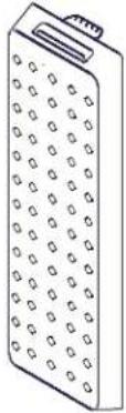 | 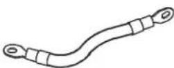 2 pan head screws to secure the ground cable 2 pan head screws to secure the ground cable | 2 tie brackets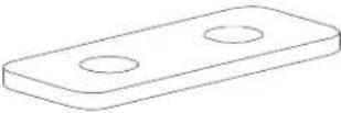 4 flat head screws to secure tie brackets 4 flat head screws to secure tie brackets | 1 pan head screw to secure the XLBP battery cable connector to an XLBP or to the UPS.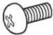 |
| Included with SRT192BP/SRT192BP2/SRT192BPJ only | |||
User Documentation CD | |||
| Included with SRT8K/SRT10K models only | |||
Battery communication (BATT COMM) cable | |||
| Included with SRT5K/SRT6K Tower models only | |||
Stabilizer brackets are supplied with the SRT5K/SRT6K modelsThe XLBP includes 1 stabilizer bracket connector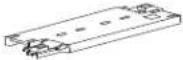 | 4 flat head screws to secure tower stabilizer brackets to the UPS | ||
| Included with Rack-Mount models only | |||
Rail Kit with instructions and hardware for installing rails in a rack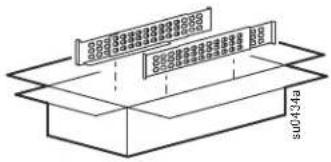 | 1 pair rack-mount brackets8 flat head screws to secure rack-mount brackets to the UPS4 ornamental screws to secure rack-mount brackets to the rails2 cage nuts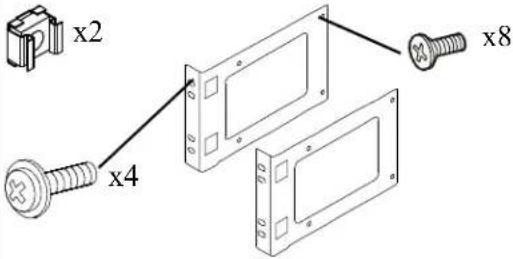 | ||
Included with SRT192BP/SRT192BP2/SRT192BPJ only
Specifications
For additional specifications, refer to the APC by Schneider Electric Web site at www.apc.com.
Environmental
| Temperature | Operating 0 °C to 40 °C (32 °F to 104 °F) | |
| Storage -15 °C to 45 °C (5 °F to 113 °F) | ||
| Maximum Elevation | Operating 0 - 3,000 m (0 - 10,000 ft) | |
| Storage 0 - 15,000 m (50,000 ft) | ||
| Humidity | 0% to 95% relative humidity, non-condensing | |
| Protection Class IP 20 rating | ||
| Note: Charge the battery modules every six months during storage.Environmental factors impact battery life. Elevated ambient temperatures, high humidity, poor quality mains power, and frequent short duration discharges will shorten battery life. | ||
Physical
The XLBP is heavy. Follow all lifting guidelines.
| Unit weight batteries included, without packaging | 91 kg (201 lb) |
| Unit weight batteries included, with packaging | 102 kg (225 lb) |
| Unit dimensions without packagingHeight x Width x Depth | 130 mm x 432 mm x 682.7 mm5.1 in x 17 in x 26.9 in |
| Unit dimensions with packagingHeight x Width x Depth | 420 mm x 600 mm x 1000 mm16.5 in x 23.6 in x 39.4 in |
| The model and serial numbers are on a small label located on the rear panel. | |
Battery

CAUTION
RISK OF HYDROGEN SULPHIDE GAS AND EXCESSIVE SMOKE
- Replace the battery at least every 5 years.
- Replace the battery immediately when the UPS indicates battery replacement is necessary.
- Replace battery at the end of its service life.
- Replace batteries with the same number and type of batteries as originally installed in the equipment.
- Replace the battery immediately when the UPS indicates a battery overtemperature condition, or when there is evidence of electrolyte leakage. Power off the UPS, unplug it from the AC input, and disconnect the batteries. Do not operate the UPS until the batteries have been replaced.
- *Replace all battery modules (including the modules in External Battery Packs) which are older than one year, when installing additional battery packs or replacing the battery module(s).
Failure to follow these instructions could result in equipment damage and minor or moderate injury.
*Contact APC by Schneider Electric Worldwide Customer Support to determine the age of the installed battery modules.
| Battery type | Sealed, maintenance-free, Valve Regulated Lead-Acid battery |
| Replacement battery moduleThis UPS has replaceable battery modules.Refer to the appropriate replacement battery user manual for installation instructions.Contact your dealer or go the APC by Schneider Electric Web site, www.apc.com for information on replacement batteries. | SRT5KXLJ/SRT8KXLJ/SRT10KXLJ models:APCRBC140JAll other models:APCRBC140 |
| Number of battery modules | 4 battery modules |
| Voltage for each battery moduleTotal voltage for the UPSAh rating | 96 VDC192 VDC5 Ah per battery module |
| XLBP cable length | 500 mm (19.7 in) |
| Battery module UPS XLBP | ||
| APCRBC140 SRT5 | KXLx/SRT5KRMXLx/SRT6KXLx/SRT6KRMXLx(except for SRT5KXLJ) | SRT192BP/SRT192RMBP |
| SRT8KXLx/SRT8KRMXLx/SRT10KXLx/SRT10KRMXLx(except for SRT8KXLJ/SRT10KXLJ) | SRT192BP2/SRT192RMBP2 | |
| APCRBC140J SRT5 | KXLJ SRT192BPJ | |
| SRT8KXLJ/SRT10KXLJ SRT192BP2J | ||
Remove Battery Modules

CAUTION
RISK OF FALLING EQUIPMENT
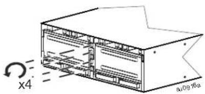
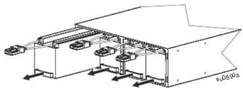
- The equipment is heavy. Each battery module weighs 17 kg (37 lb).
• Always practice safe lifting techniques adequate for the weight of the equipment. - Remove the battery modules before installing the UPS.
- Use the battery module handle to slide the battery modules in or out of the UPS.
- Do not use the battery module handle to lift or carry the battery module.
Failure to follow these instructions can result in equipment damage and minor or moderate injury.
1
natural_image
Technical line drawing of a multi-chamber electronic device with no visible text or symbols2

text_image
Diagram showing a device with multiple ports and directional arrows, possibly indicating flow or movement in a system.3
natural_image
Technical line drawing of a mechanical assembly with multiple components and mounting brackets (no text or symbols)Rack-Mount Installation
UPS model may differ in appearance from those depicted in these graphics. The XLBP installation process is identical for all models.
Refer to the rail kit Installation Guide for instructions on rail installation.

CAUTION
RISK OF FALLING EQUIPMENT
- The equipment is heavy. Always practice safe lifting techniques adequate for the weight of the equipment.
• Always use the recommended number of screws to secure brackets to the UPS.
• Always use the recommended number of screws and cage nuts to secure the UPS to the rack.
• Always install the UPS at the bottom of the rack.
• Always install the XLBP below the UPS in the rack.
Failure to follow these instructions can result in equipment damage and minor or moderate injury
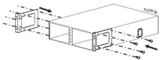
① Secure two brackets to the XLBP. Use four screws in each bracket.
text_image
Technical diagram showing airflow or particle movement between a rectangular device with labeled dimensions and directional arrows② Install two cage nuts.
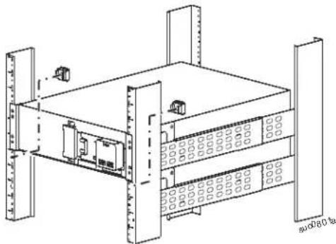
natural_image
Technical line drawing of a server rack unit with multiple drive bays and ventilation grilles (no text or labels)③ Rest the XLBP on the rail shelves. Slide the XLBP into the rack.
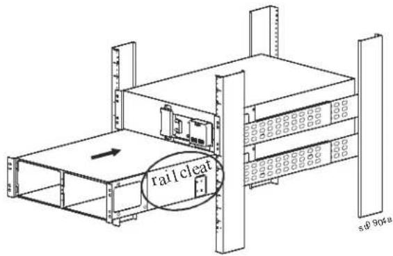
text_image
rail cleat s.0 904a④ Secure the XLBP to the rack. Use two screws in each bracket.
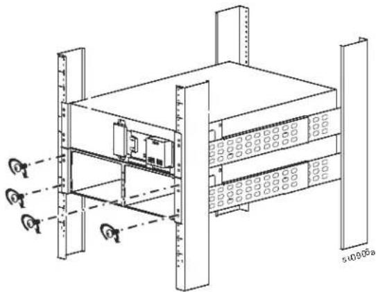
natural_image
Technical line drawing of a server rack with mounting holes and ventilation grilles (no text or symbols)⑤ Install four battery modules.
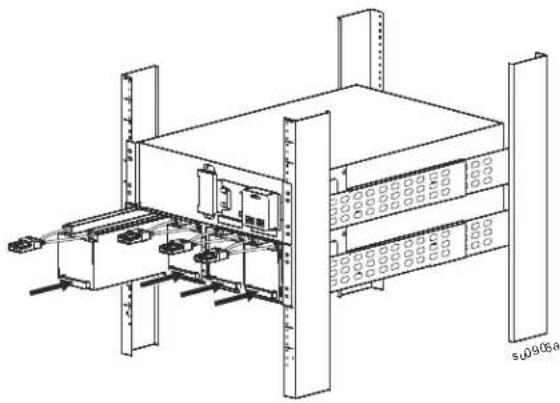
natural_image
Technical line drawing of a server rack unit with mounting brackets and internal components (no text or symbols)6 Connect four battery modules.
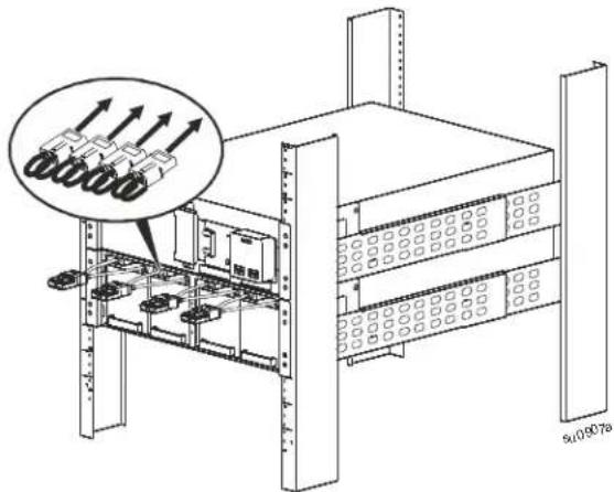
text_image
Technical diagram of server rack with labeled components and a magnified inset showing component arrangement⑦ Reinstall the battery compartment doors. Tighten the thumbscrews to secure the doors.
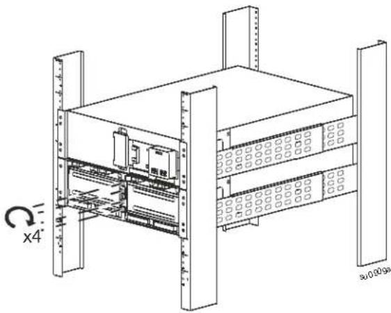
natural_image
Technical line drawing of a server rack unit with mounting brackets and ventilation grilles (no text or symbols)⑧ UPS models SRT5K or SRT6K with one XLBP
Install one XLBP bezel and one UPS bezel.
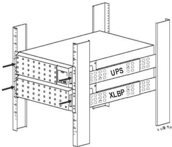
text_image
UPS XLBP s u@ 1aUPS models SRT8K or SRT10K with one XLBP
Install one XLBP bezel and two UPS bezels.
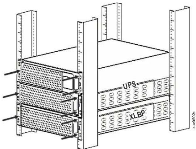
text_image
UPS XLBP 80.2aTower Installation

CAUTION
RISK OF FALLING EQUIPMENT
• The equipment is heavy. Each battery module weighs 17 kg (37 lb).
• Always practice safe lifting techniques adequate for the weight of the equipment.
- Remove the battery modules before installing the UPS.
- Use the battery module handle to slide the battery modules in or out of the UPS.
- Do not use the battery module handle to lift or carry the battery module.
Failure to follow these instructions can result in equipment damage and minor or moderate injury
UPS model may differ in appearance from those depicted in these graphics. The XLBP installation process is identical for all models.
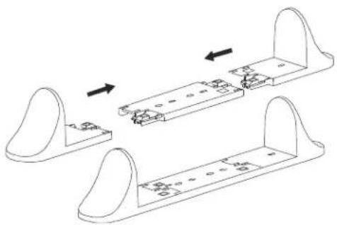
Stabilizer bracket installation UPS models SRT5K/SRT6K only
Stabilizer brackets are supplied with the SRT5K/SRT6K UPS models.
natural_image
Technical line drawing of a mechanical assembly with two views and internal components (no text or symbols)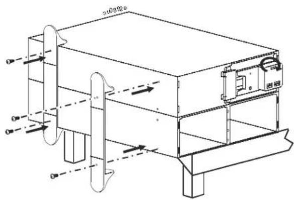
text_image
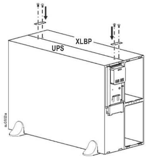
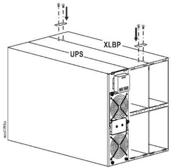
s00892a s00892aTie bracket installation all UPS models
① UPS models SRT5K/SRT6K with one XLBP
text_image
UPS XLBP 0.01633a② UPS models SRT8K/SRT10K with one XLBP
text_image
XLBP UPS 9100788aInstall battery modules and bezels SRT5K/SRT6K UPS models
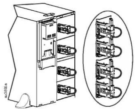
① Slide four battery modules into the XLBP. Connect four battery modules.
natural_image
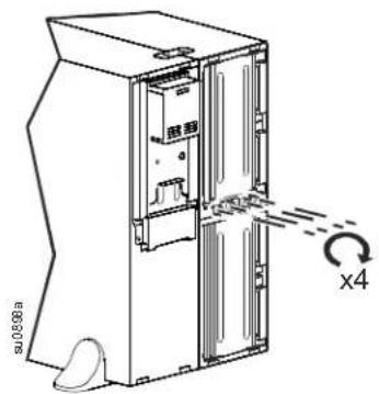
Technical line drawing of an electrical control cabinet with multiple modules and a separate view of its internal components (no text or symbols present)② Reinstall the battery compartment doors. Tighten the thumbscrews to secure two doors.
text_image
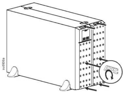
u0888a x4③ Install two bezels.
text_image
su0501a 图腾 ARCSRT8K/SRT10K UPS models
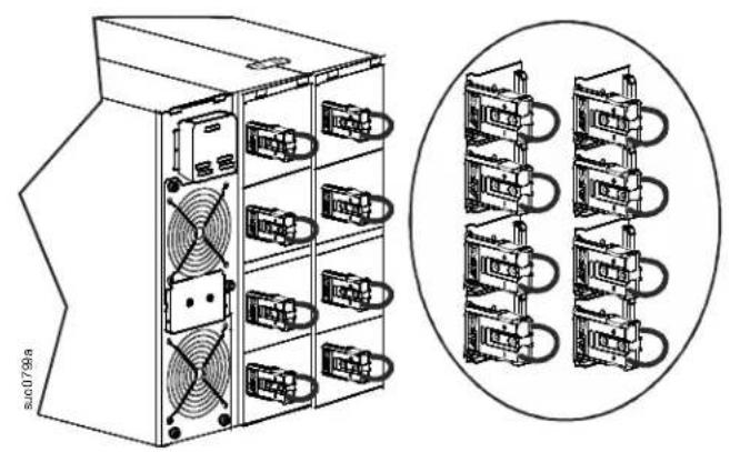
① Slide four battery modules into the UPS and four battery modules into the XLBP. Connect eight battery modules.
② Reinstall the battery compartment doors. Tighten the thumbscrews to secure four doors.
natural_image
Technical line drawing of a server rack with fan and cooling unit, alongside a schematic view of multiple connected units (no text or symbols present)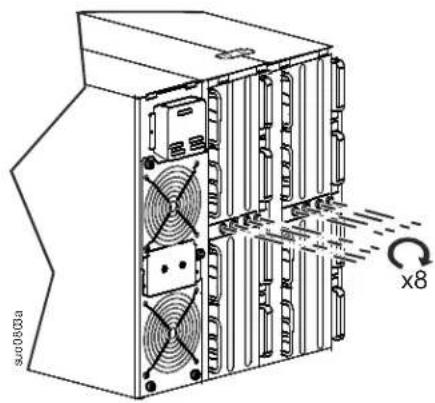
text_image
sv00803a x8③ Install three bezels.
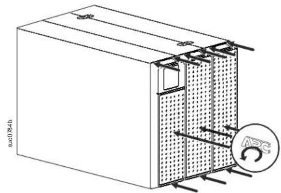
text_image
s.0784b APCConnect Ground and Battery Cables
UPS model may differ in appearance from those depicted in these graphics. The process is identical for all models.
SRT5K/SRT6K models
Connect ground cables
Recommended screw torque, 2.72 Nm (24 lbf-in)
Connect external battery pack cables
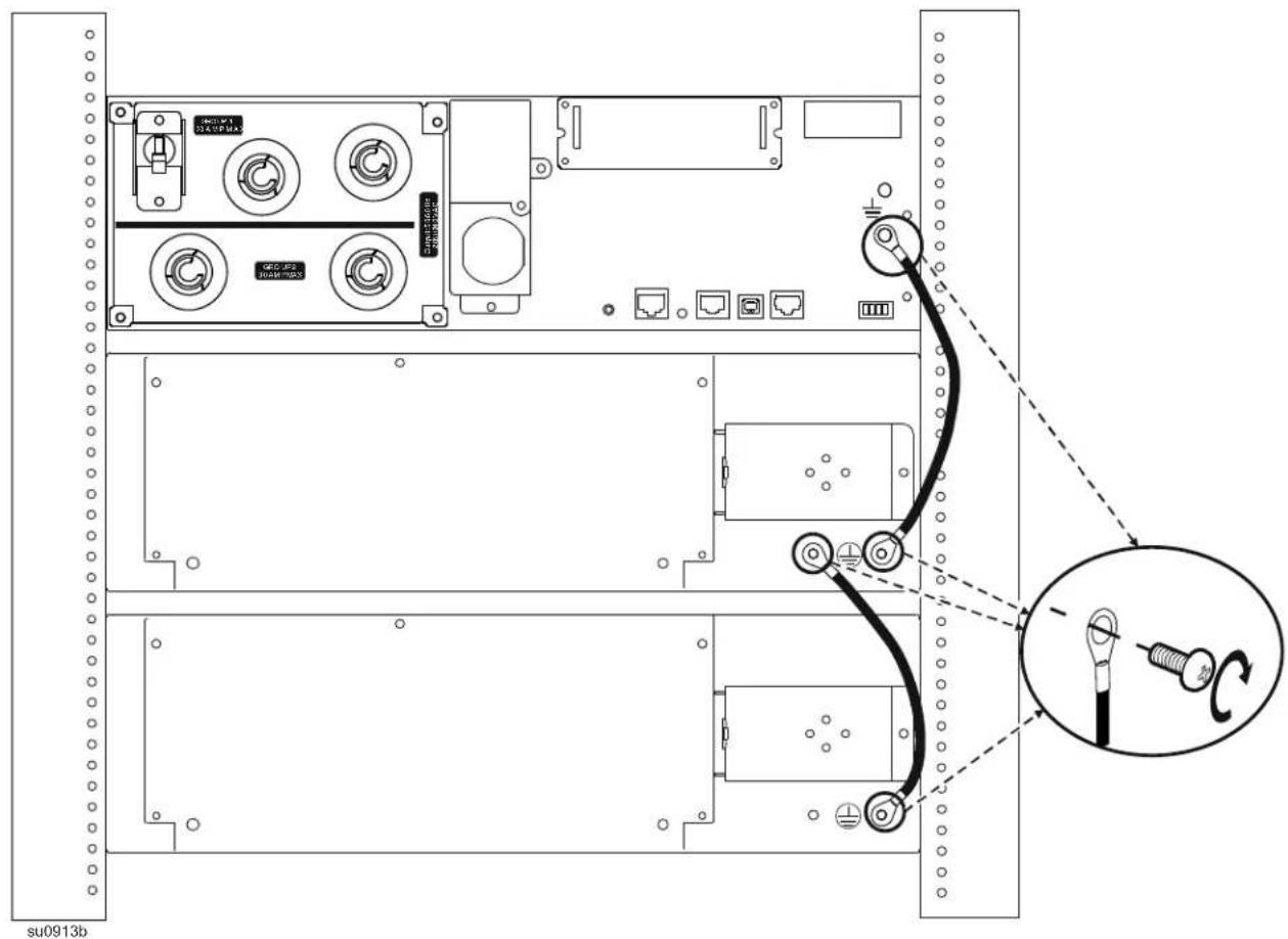
text_image
SU0913b GEQ-02 SUNH-023The UPS external battery pack connector has a cover, secured with a screw.
Remove the screw and the cover.
Connect the external battery pack.
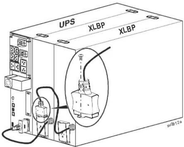
text_image
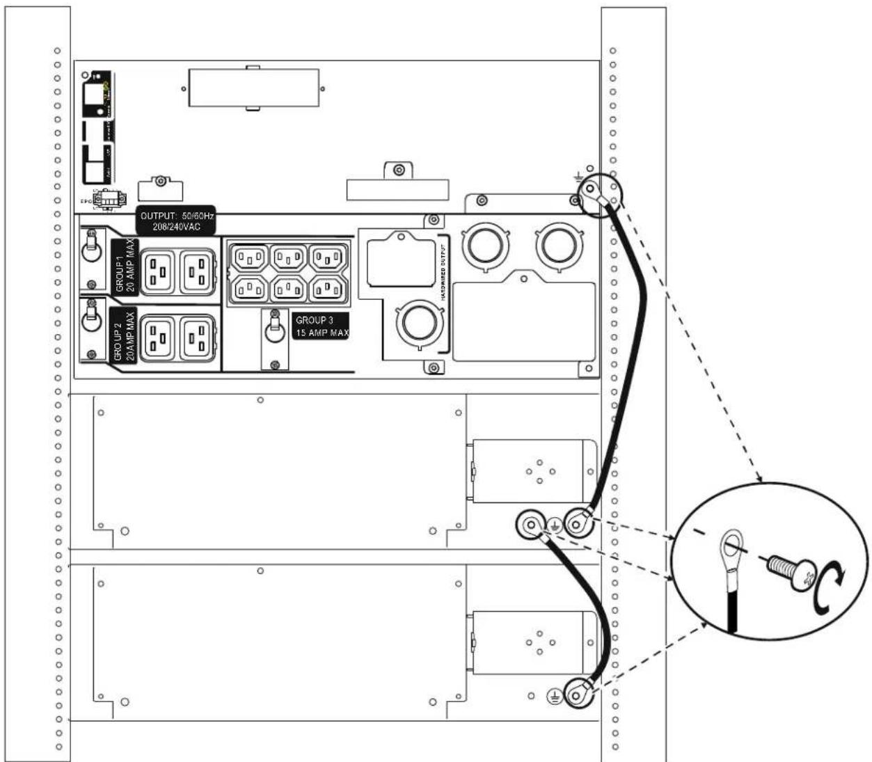
UPS XLBP XLBP su0012aSRT8K/SRT10K models
Connect ground cables
Recommended screw torque, 2.72 Nm (24 lbf-in)
text_image
OUTPUT: 50/60Hz 208/240VAC GROUP-1 20 AMP MAX GROUP-2 20 AMP MAX GROUP 3 15 AMP MAXsuo0806b
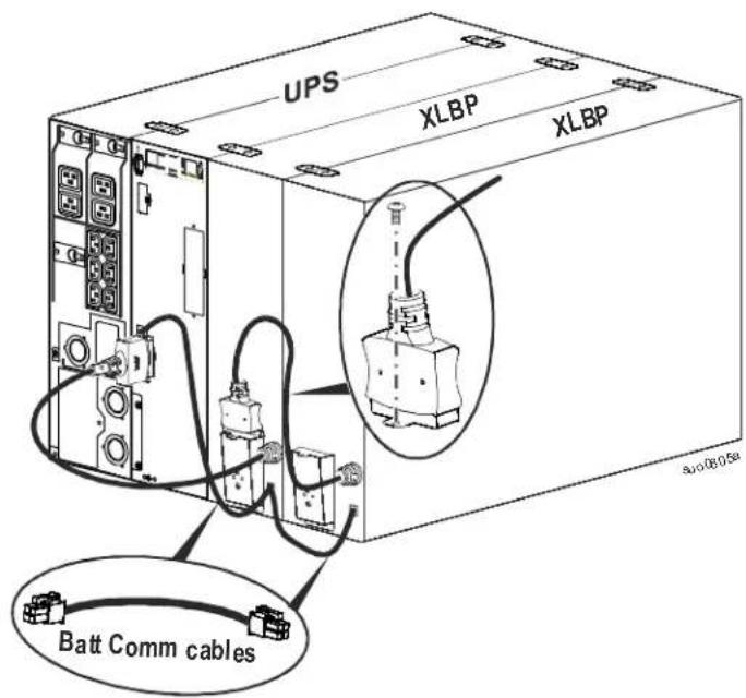
Connect UPS battery pack, external battery packs and communication cables
The UPS external battery pack connector has a cover secured with a screw.
Remove the screw and the cover.
Connect the external battery pack.
text_image
UPS XLBP XLBP Batt Comm cablesSmart Battery Management
Definitions
- Battery Module: A string of battery cells arranged to produce a battery assembly with a connector.
- Replaceable Battery Cartridge (RBC): An APC battery cartridge consisting of two battery modules. Replacement RBCs can be ordered from the APC by Schneider Electric Web site, www.apc.com.
• Smart External Battery Pack (XLBP): An enclosure that contains RBC(s) and battery management electronics.
- User Interface (UI): Any interface by which a user can interact with the system. This may include a UPS display interface, a network management interface or PowerChute™ Network Shutdown software.
Note: Do not use a battery that is not approved by APC by Schneider Electric.
The system will not detect the presence of a non APC by Schneider Electric approved battery and may adversely affect the operation of the system.
Use of a non APC by Schneider Electric approved battery will void the manufacturer warranty.
Maintenance
- RBC maintenance: The APC by Schneider Electric RBC uses sealed lead acid battery cells and does not require maintenance.
- Runtime Test (Calibration): This should be performed anytime the steady state load is changed significantly, for example a new server is added to or removed from the UPS load.
- Battery health monitoring: The battery energy output and voltage are monitored to assess the health of the installed batteries when the UPS is operating on battery.
Battery health monitoring is done during a UPS Self Test, a Runtime Calibration Test, and when the UPS is operating on battery power.
The UPS can be configured to perform periodic, automatic Self Tests.
End of useful life
- Near end of life notification: An alert message will appear on the UPS display interface screen when each RBC is approaching the end of its useful life. For configuration details refer to Replacement Notification Time and Replacement Battery Alarm Time in the UPS Operation Manual. The estimated replacement date for each RBC is available through the UI.
- Needs replacement notification: The UPS display interface screen shows when RBC replacement is required. The RBC must be replaced as soon as possible. When an RBC requires replacement, the UPS display interface may recommend that additional RBCs be replaced if they will soon reach the end of their useful life.
Note: Continued operation after end of useful life notification may cause damage to the batteries.
• Recycling: Remove the RBC from the XLBP. Recycle the RBC. Do not disassemble an RBC.
Recommended actions after installing new RBCs or XLBPs
Refer to the UPS Operation Manual for details on Test and Diagnostics Menu options for the following tests:
- Self Test
- Runtime Test
• Alarm Test
The following actions should be performed after installing a new RBC or XLBP:
- Verify that the UPS is connected to input power and output power is turned on. Refer to the Operation section in this manual for instructions.
- When a new XLBP is installed, verify that the XLBP is detected by the system.
- Perform a UPS Alarm Test.
- Check that the LED on all installed XLBPs continuously flashes.
- To verify that installation of a replacement battery cartridge (RBC), has been successful, go to the UPS display interface. Use the Status menus to verify that the UPS recognizes the RBCs.
- Verify that the UPS load is greater than 400 watts. This will appear on the UPS display interface.
• Perform a UPS Self Test. - If at the time of XLBP installation UPS input power is not available, turn on the UPS output from battery power for 30 seconds. This will allow the UPS to detect all installed RBCs. Refer to the UPS Operation Manual for instructions on how to turn the UPS on and off.
- Verify on the UPS display interface that the installation dates for the replaced RBCs are set to the current date. The installation dates can be changed manually on the UPS display interface. If all RBCs have been replaced at the same time, all installation dates can be changed simultaneously. For configuration details refer to Battery Install Date in the Operation Manual.
- Allow the system to charge for 24 hours to ensure full runtime capability.
- Initiate a Runtime Calibration Test through the UI.
User interface
View Status/Error notifications: The status of connected XLBPs can be viewed using the UPS display interface menu options.
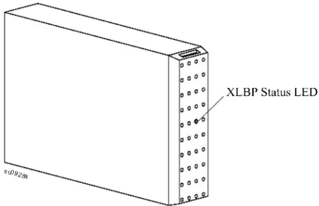
- XLBP Status LED: The XLBP LED illuminates red to indicate three possible states.
- Off: No message. This is the default state.
- Solid red: XLBP cannot communicate with the UPS. The XLBP controller is not functional.
- Flashing red:
- For identification purposes each XLBP is automatically assigned a number. To verify the number of a specific XLBP, use the UPS display interface menu options. Select an XLBP number. The LED will flash on the XLBP assigned to that number
- XLB P LED test: From the UPS display interface, LED functionality can be tested by issuing an Alarm Test. This command causes the LED on each connected XLBP to flash.
- System interfaces: Battery status, alerts, and measurements are shown on the UPS display interface screen. Refer to the UPS Operation Manual.
text_image
XLBP Status LED s10928Troubleshooting
| Issues Possible Cause Solution | ||
| XLBP LED flashes. • The UPS display interface is requesting XLBP status• Alarm Test has been requested by the UPS• Indicates that an RBC needs to be replaced | • No action is necessary.• No action is necessary.• Refer to the UPS display interface screen for information. | |
| XLBP LED remains illuminated | Potential hardware error exists | • Contact APC by Schneider Electric Customer Support. Refer to the Service section in the Operation Manual for contact information. |
| UPS display interface shows an RBC disconnected message. | • RBC is not connected• RBC hardware error exists | Connect the RBCs. Verify that the UPS recognizes the RBCs.Perform a UPS Self Test.If the message remains on the display interface screen replace the RBC. |
| XLBP is not recognized. • Communication issue exists• Potential hardware error exists | • Be sure the battery connections to the XLBPs are secure.• Be sure the connection between the XLBPs and the UPS are secure.• Perform an Alarm Test to verify that the LED flashes.• If issue persists, contact APC by Schneider Electric Customer Support. Refer to the Service section in the Operation Manual for contact information. | |
| UPS display interface shows XLBP disconnected message. | • Power cable is not securely connected to an XLBP or to the UPS• XLBP hardware error | • Be sure the battery connections to the XLBPs are secure.• Perform an Alarm Test to verify that the LED flashes.• If issue persists, contact APC by Schneider Electric Customer Support. Refer to the Service section in the Operation Manual for contact information. |
Limited Factory Warranty
Schneider Electric IT Corporation (SEIT), warrants its products to be free from defects in materials and workmanship for a period of two (2) years including the batteries from the date of purchase. The SEIT obligation under this warranty is limited to repairing or replacing, at its own sole option, any such defective products. Repair or replacement of a defective product or parts thereof does not extend the original warranty period.
This warranty applies only to the original purchaser who must have properly registered the product within 10 days of purchase. Products may be registered online at warranty.apc.com.
SEIT shall not be liable under the warranty if its testing and examination disclose that the alleged defect in the product does not exist or was caused by end user or any third person misuse, negligence, improper installation, testing, operation or use of the product contrary to SEIT recommendations or specifications. Further, SEIT shall not be liable for defects resulting from: 1) unauthorized attempts to repair or modify the product, 2) incorrect or inadequate electrical voltage or connection, 3) inappropriate on site operation conditions, 4) Acts of God, 5) exposure to the elements, or 6) theft. In no event shall SEIT have any liability under this warranty for any product where the serial number has been altered, defaced, or removed.
EXCEPT AS SET FORTH ABOVE, THERE ARE NO WARRANTIES, EXPRESS OR IMPLIED, BY OPERATION OF LAW OR OTHERWISE, APPLICABLE TO PRODUCTS SOLD, SERVICED OR FURNISHED UNDER THIS AGREEMENT OR IN CONNECTION HEREWITH.
SEIT DISCLAIMS ALL IMPLIED WARRANTIES OF MERCHANTABILITY, SATISFACTION AND FITNESS FOR A PARTICULAR PURPOSE.
SEIT EXPRESS WARRANTIES WILL NOT BE ENLARGED, DIMINISHED, OR AFFECTED BY AND NO OBLIGATION OR LIABILITY WILL ARISE OUT OF, SEIT RENDERING OF TECHNICAL OR OTHER ADVICE OR SERVICE IN CONNECTION WITH THE PRODUCTS.
THE FOREGOING WARRANTIES AND REMEDIES ARE EXCLUSIVE AND IN LIEU OF ALL OTHER WARRANTIES AND REMEDIES. THE WARRANTIES SET FORTH ABOVE CONSTITUTE SEIT'S SOLE LIABILITY AND PURCHASER EXCLUSIVE REMEDY FOR ANY BREACH OF SUCH WARRANTIES. SEIT WARRANTIES EXTEND ONLY TO ORIGINAL PURCHASER AND ARE NOT EXTENDED TO ANY THIRD PARTIES.
IN NO EVENT SHALL SEIT, ITS OFFICERS, DIRECTORS, AFFILIATES OR EMPLOYEES BE LIABLE FOR ANY FORM OF INDIRECT, SPECIAL, CONSEQUENTIAL OR PUNITIVE DAMAGES, ARISING OUT OF THE USE, SERVICE OR INSTALLATION OF THE PRODUCTS, WHETHER SUCH DAMAGES ARISE IN CONTRACT OR TORT, IRRESPECTIVE OF FAULT, NEGLIGENCE OR STRICT LIABILITY OR WHETHER SEIT HAS BEEN ADVISED IN ADVANCE OF THE POSSIBILITY OF SUCH DAMAGES. SPECIFICALLY, SEIT IS NOT LIABLE FOR ANY COSTS, SUCH AS LOST PROFITS OR REVENUE, WHETHER DIRECT OR INDIRECT, LOSS OF EQUIPMENT, LOSS OF USE OF EQUIPMENT, LOSS OF SOFTWARE, LOSS OF DATA, COSTS OF SUBSTITUANTS, CLAIMS BY THIRD PARTIES, OR OTHERWISE.
NOTHING IN THIS LIMITED WARRANTY SHALL SEEK TO EXCLUDE OR LIMIT SEIT LIABILITY FOR DEATH OR PERSONAL INJURY RESULTING FROM ITS NEGLIGENCE OR ITS FRAUDULENT MISREPRESENTATION OF TO THE EXTENT THAT IT CANNOT BE EXCLUDED OR LIMITED BY APPLICABLE LAW.
To obtain service under warranty you must obtain a Returned Material Authorization (RMA) number from customer support. Customers with warranty claims issues may access the SEIT worldwide customer support network through the APC by Schneider Electric Web site: www.apc.com. Select your country from the country selection drop down menu. Open the Support tab at the top of the web page to obtain information for customer support in your region. Products must be returned with transportation charges prepaid and must be accompanied by a brief description of the problem encountered and proof of date and place of purchase.
APC™ by Schneider Electric Worldwide Customer Support
Customer support for this or any other APC ^™ by Schneider Electric product is available at no charge in any of the following ways:
- Visit the APC by Schneider Electric Web site to access documents in the APC Knowledge Base and to submit customer support requests.
- www.apc.com (Corporate Headquarters)
Connect to localized APC by Schneider Electric Web sites for specific countries, each of which provides customer support information.
- www.apc.com/support/
Global support searching APC Knowledge Base and using e-support.
- Contact APC by Schneider Electric Customer Support Center by telephone or e-mail.
- Local, country specific centers: go to www.apc.com/support/contact for contact information.
- For information on how to obtain local customer support, contact the APC by Schneider Electric representative or other distributor from whom you purchased your APC by Schneider Electric product.