95-3318B - Kit voiture Metra - Free user manual and instructions
Find the device manual for free 95-3318B Metra in PDF.


User questions about 95-3318B Metra
0 question about this device. Answer the ones you know or ask your own.
Ask a new question about this device
Download the instructions for your Kit voiture in PDF format for free! Find your manual 95-3318B - Metra and take your electronic device back in hand. On this page are published all the documents necessary for the use of your device. 95-3318B by Metra.
USER MANUAL 95-3318B Metra
Installation instructions for part 95-33188
Chevy Malibu (with automatic climate controls) 2013-up 95-3318B
KIT FEATURES
• Double DIN radio provision with pocket
- Painted black to match the factory dash
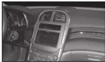
natural_image
Interior view of a car dashboard with steering wheel, air conditioner, and digital display (no visible text or symbols)KIT COMPONENTS
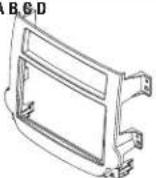
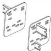
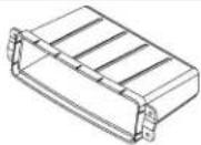
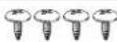
• A) Radio trim panel • B) Brackets • C) Pocket • D) (4) #8 x 3/8" Phillips screws
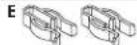
• E) (2) White panel clips • Axxess interface and harness (not shown)
A B C D
WIRING & ANTENNA CONNECTIONS (sold separately)
Wiring Harness: • Axxess interface included
Antenna Adapter: • 40-EU55
Table of Contents
Dash Disassembly
- Chevy Malibu
(with automatic climate controls) 2013-up ..... 2
Kit Assembly
- Double DIN radio provision with pocket .... 3
Axxess Interface Installation 4 - Connections to be made 4-6
- Installing the 95-3318B....6
- Initializing the 95-3318B....6
- Adjusting the 95-3318B....6
- Personalization Menu and Climate Control Status .... 7
TOOLS REQUIRED
- Panel removal tool
- Phillips screwdriver
- Socket wrench (9/32")
CAUTION! Metra recommends disconnecting the negative battery terminal before beginning any installation, unless the vehicle manufacturer recommends against so. Please check with your local Dealership for more information. All accessories, switches, climate controls panels, and especially air bag indicator lights must be connected before reconnecting the battery or cycling the ignition. Also, do not remove the factory radio with the key in the on position, or the vehicle running. It would be best to remove the key from the ignition and then wait a few seconds before removing the factory radio.
95-3318B
Dash Disassembly
2013 Chevy Malibu
(with automatic climate controls)
With the key in the off position:
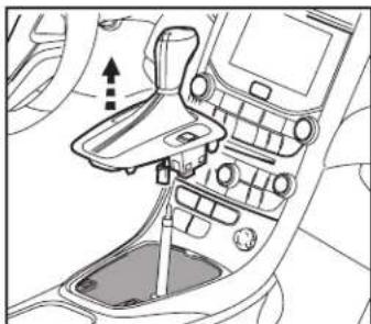
- Unclip and lift up the panel surrounding the shifter. (Figure A)
- Unplug the two pin connector to the shift knob then pull up on the shift knob to remove it and the panel surrounding it. (Figure A)
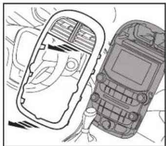
- Unclip and remove the trim panel surrounding the center stack including the a/c vents. (Figure B)
- Remove (12) 9/32" screws securing everything in the center of the dash then unplug and remove all of the components.
- Remove (4) 9/32" screws securing the radio chassis.
Continue to kit assembly
natural_image
Interior view of a car dashboard and steering wheel (no text or symbols visible)(Figure A) (Figure A)
natural_image
Interior view of a car dashboard seat assembly (no text or symbols visible)(Figure B)
2014-up Chevy Malibu
(with automatic climate controls)
With the key in the off position:
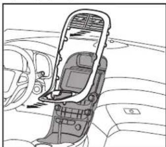
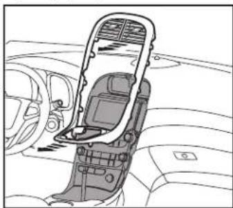
- Unclip and remove the trim panel surrounding the center stack including the a/c vents. (Figure A)
- Remove (12) 9/32" screws securing everything in the center of the dash then unplug and remove all of the components.
- Remove (4) 9/32" screws securing the radio chassis.
Continue to kit assembly
natural_image
Line drawing of two vehicles, one open and one closed, with no visible text or symbols
95-3318B
Kit Assembly
ISO DDIN radio provision
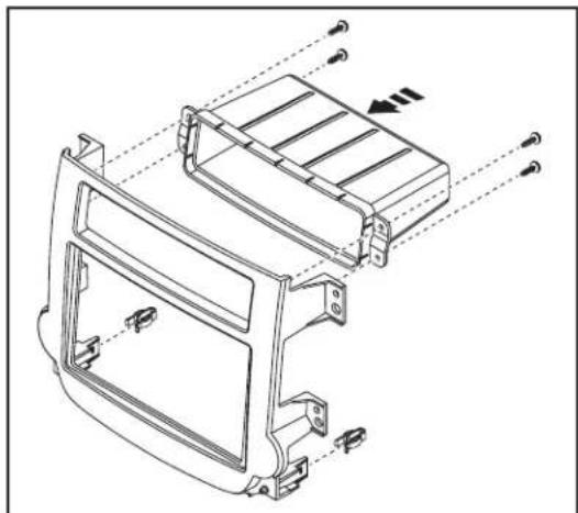
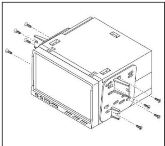
- Install the panel clips onto the radio housing panel. (Figure A)
- Attach the upper pocket with the provided (4) #8 x 3/8" Phillips screws. (Figure A)
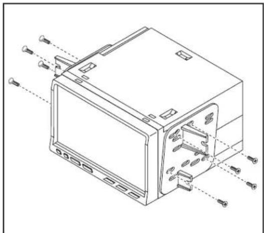
- Attach the radio brackets to the aftermarket radio with the screws supplied with the radio. (Figure B)
Continue to Axxess Interface Installation
natural_image
Technical line drawing of a car front panel with mounting brackets and structural ribs (no text or symbols)(Figure A) (Figure B)
natural_image
Technical line drawing of a device housing with mounting holes and screw fasteners (no text or symbols)Axxess Interface Installation Connections to be made
FEATURES
- Retains the factory personalization menu and climate controls status
- Retains OnStar
- Prewired ASWC-1 harness included (ASWC-1 sold separately)
ATTENTION: The Rearview Camera Input is used to display the Personalization Menu and the Climate Control status. If the aftermarket radio does not have a screen with a Rearview Camera Input, then there will be no visualization of the Climate Controls Status or Personalization Menu. An externally mounted screen could be substituted in this situation.
INTERFACE COMPONENTS
- Axxess interface
• 3318 harness
• 18-pin harness with stripped leads
• 20-pin gray harness
• 4-pin to 4-pin resistor pad harness
TOOLS REQUIRED
• Cutting tool • Crimping tool • Tape
- Connectors (example: butt-connectors, bell caps, etc.)
From the 18-pin harness to the aftermarket radio:
- Connect the (2) Red wires to the accessory wire. (If installing an ASWC-1, there will be a Red wire there to connect as well.)
- Connect the Orange wire to the illumination wire. (If the aftermarket radio has no illumination wire, tape off the Orange wire.)
- Connect the Blue/White wire to the amp turn on wire (this wire must be connected to hear sound from the factory amplifier).
- Connect the Brown wire to the mute wire of the aftermarket radio. If the radio has no mute wire, tape it off and disregard it.
- Connect the White wire to the left front positive speaker output.
- Connect the White/Black wire to the left front negative speaker output.
- Connect the Gray wire to the right front positive speaker output.
- Connect the Gray/Black wire to the right front negative speaker output.
The following (3) wires are for aftermarket multimedia/navigation radios that provide these wires (if not required, tape them off and disregard them):
- Connect the Light Green wire to the parking brake wire (if applicable).
- Connect the Green/Purple wire to the reverse wire.
Note: This wire must be connected for the interface to activate the Personalization Menu and the Climate Control Status to the aftermarket radio.
- Connect the Blue/Pink wire to the speed sense wire (if applicable).
Continued on the next page
95-3318B
Connections to be made
Note: Some models do not have speed sense on the data-bus. Refer to the 20-pin Gray harness to the aftermarket radio step. If you do not have a wire populated on the factory side of the 20-pin harness, connect this wire instead.
- Connect the Yellow RCA jack to the rearview camera input.
Note: The Rearview Camera Input is used to display the Personalization Menu and the Climate Control status. If the aftermarket radio does not have a screen with a Rearview Camera Input, then there will be no visualization of the Climate Controls Status or Personalization Menu. An externally mounted screen could be substituted in this situation.
From the 3318 harness to the aftermarket radio:
- Connect the Black wire to the ground wire.
- Connect the Yellow wire to the battery wire.
For models without a BOSE sound-system:
- Cut the resistors off from the Green, Green/Black, Purple, and Purple/Black wires below the heat shrink.
- Connect the Green wire to the left rear positive speaker output.
- Connect the Green/Black wire to the left rear negative speaker output.
- Connect the Purple wire to the right rear positive speaker output.
- Connect the Purple/Black wire to the right rear negative speaker output.
- Leave connected the 4-pin connector that has the White, White/Black, Gray, Gray/Black wires.
Note: The 4-pin to 4-pin resistor pad harness will not be used in this application.
For models with a BOSE sound-system:
- Connect the Green wire to the left rear positive speaker output.
- Connect the Green/Black wire to the left rear negative speaker output.
- Connect the Purple wire to the right rear positive speaker output.
- Connect the Purple/Black wire to the right rear negative speaker output.
- Disconnect the 4-pin harness that has the White, White/Black, Gray, Gray/Black wires, and then connect the supplied 4-pin to 4-pin resistor pad harness.
- Connect the Red and White RCA jacks to the audio AUX-IN on the aftermarket radio (if so equipped).
Note:
o This will allow you to retain the 3.5 AUX-IN JACK in the console.
o The 3.5 jack can only be used if it is a single AUX-IN jack.
o If the AUX-IN jack has a USB port, neither can be used.
- The Black/Yellow wire is used for OnStar level adjustment for models that do not come equipped with steering wheel controls. See OnStar Level Adjustment for further instructions.
- Tape off and disregard the White/Red and White/Green wires, they will not be used in this application.
- The female Yellow RCA jack will connect to the male Yellow RCA jack on the 20-pin Gray harness.
Note: The 4-pin black connector will not be used in this application.
Continued on the next page
Connections to be made Installing the 95-3318B
12-pin pre-wired ASWC-1 harness:
- This harness is to be used along with the optional ASWC-1 (not included) to retain steering wheel audio controls. If the ASWC-1 is not being used, disregard this harness. If it will be used, please refer to the ASWC-1 instructions for radio connections and programming.
Note: Disregard the harness that comes with the ASWC-1.
- Connect the Red wire to the accessory wire.
Note: The relay attached to the Axxess interface is only for audible turn signal clicks. No extra steps are required to retain this feature, so leave the relay as-is.
From the 20-pin Gray harness
To the Axxess interface:
- The male Yellow RCA jack will connect to the female Yellow RCA jack on the 3318 harness.
To the aftermarket radio:
- Connect the Blue/Pink wire to the speed sense wire (if applicable). Note: Only connect this wire if it is populated on the factory side harness.
- Connect the 3318 and 18-pin harness into the interface.
- With the key in the off position, connect the 3318 and 20-pin harness into the vehicle
- With all connections completed, reconnect the negative battery terminal.
Note: If using the ASWC-1, connect it after you initialize and test the 95-3318B, with the key in the off position. - Mount the new radio assembly into the dash, and then reassemble the dash in reverse order of disassembly, using the 95-3318B radio housing panel.
Initializing the 95-3318B
- Initialize the interface by turning the ignition on for 30 seconds, then turn the ignition back off, then back on again.
- Push the OnStar button; the radio should mute, and you should hear the OnStar voice. Push the OnStar cancel button; the radio should un-mute and play again. Note: The radio will turn off instead if the mute wire is not connected.
Adjusting the 95-3318B
OnStar level adjustment:
- Press the OnStar button to activate it.
- While OnStar is speaking, press the "Volume-Up" or "Volume-Down" buttons on the steering wheel to raise or lower the OnStar level.
- If the vehicle does not come equipped with steering wheel controls, find the Black/Yellow wire on the 24-pin harness.
- While OnStar is speaking, tap the Black/Yellow wire to ground. Once the OnStar level is set, it will stay at that level until the Black/Yellow wire is tapped to ground again.
95-33188
Personalization Menu and Climate Control Status
ATTENTION: The Rearview Camera Input is used to display the Personalization Menu and the Climate Control Status. If the aftermarket radio does not have a screen with a Rearview Camera Input, then there will be no visualization of the Climate Controls Status or Personalization Menu. An externally mounted screen could be substituted in this situation. If there is no visual, please go back and check the wiring and settings in the radio.
Personalization Menu
Note: The steering wheel controls for the personalization menu will override the controls for the radio, and the Push-to-Talk (OnStar) button on the steering wheel control will be disabled.
Note: If installing an ASWC-1 (sold separately), the PTT (OnStar) button on the steering wheel cannot be programmed for Dual Assignment.
- Press and hold the Push-to-Talk (PTT) button on the steering wheel for 3-5 seconds to enter the personalization screen. The climate control screen will appear first; press Push-to-Talk (PTT) one more time to enter the personalization menu
Note: The menu has a 5-7 timeout feature. With no interaction, the menu will revert back to the radio, and the procedure will need to be repeated. - To navigate through the menu, you will continue to use the steering wheel control buttons. Touch points are not available in this menu, as well as with the comfort controls.
• The controls are as follows:
Volume Up = Up
Volume Down = Down
Source (SRC) = Enter
Mute/Hang up = Back or Return
Seek Up and Seek Down = Not used
Climate Control Status
- The use of the factory controls will interrupt the visual screen on the radio, and show the status of the changes being made instead.
Note: For some aftermarket radios, there is a delay switching to the "Rearview Camera Input".
Note: This menu has a timeout feature; after 5 seconds of no climate control use, the visual will return back to the radio.

Installation instructions for part 95-33188
IMPORTANT
If you are having difficulties with the installation of this product, please call our Tech Support line at 1-800-253-TECH. Before doing so, look over the instructions a second time, and make sure the installation was performed exactly as the instructions are stated. Please have the vehicle apart and ready to perform troubleshooting steps before calling.

KNOWLEDGE IS POWER
Enhance your installation and fabrication skills by enrolling in the most recognized and respected mobile electronics school in our industry. Log onto www.installerinstitute.com or call 800-354-6782 for more information and take steps toward a better tomorrow.

Metra recommends MECP certified technicians
natural_image
Interior view of a car dashboard with steering wheel, air conditioner, and digital display (no visible text or symbols)COMPONENTES DEL KIT
natural_image
Interior view of a car dashboard and seat area showing directional control buttons and a central sink (no text or symbols)(Figura A) (Figura A)
natural_image
Interior view of a car dashboard and seat assembly (no text or symbols visible)(Figura B)
2014-up Chevy Malibu
natural_image
Line drawing of a car interior with a flatbed frame and a mobile phone on the right (no text or symbols)
95-3318B
Ensamble del kit
natural_image
Technical line drawing of a car front panel with mounting brackets and structural ribs (no text or symbols)(Figura A) (Figura B)
natural_image
Technical line drawing of a device housing with mounting holes and screw fasteners (no text or symbols)
95-33188