
TKN/TKG-671R32 - Air-conditioner Toyotomi - Free user manual and instructions
Find the device manual for free TKN/TKG-671R32 Toyotomi in PDF.


| Product Type | Split-type air conditioner (indoor unit TKN, outdoor unit TKG) |
| Model | TKN/TKG-671R32 |
| Brand | Toyotomi |
| Refrigerant | R32 |
| Cooling Capacity | Approx. 7.1 kW (24,200 BTU/h) |
| Heating Capacity | Approx. 8.0 kW (27,300 BTU/h) |
| Power Supply | 220-240 V, 50 Hz, Single Phase |
| Cooling Power Input | Approx. 2.2 kW |
| Heating Power Input | Approx. 2.4 kW |
| Energy Efficiency Ratio (EER) | Approx. 3.2 |
| Indoor Unit Dimensions (WxHxD) | Approx. 1100 x 315 x 235 mm |
| Outdoor Unit Dimensions (WxHxD) | Approx. 900 x 650 x 320 mm |
| Indoor Unit Weight | Approx. 14 kg |
| Outdoor Unit Weight | Approx. 45 kg |
| Air Flow (Indoor) | Up to 900 m³/h (high speed) |
| Noise Level (Indoor) | Approx. 45 dB(A) (high speed) |
| Noise Level (Outdoor) | Approx. 55 dB(A) |
| Operation Modes | Cool, Heat, Fan, Dry, Auto |
| Filter Type | Washable mesh filter, optional anti-bacterial filter |
| Remote Control | Wireless infrared remote with LCD display |
| Timer Function | 24-hour on/off timer |
| Special Features | Auto restart, sleep mode, turbo mode, self-cleaning function |
| Maintenance | Clean filter every 2 weeks; professional maintenance recommended annually |
| Safety Protections | Overcurrent protection, compressor time delay, anti-freeze protection |
| Certifications | CE, RoHS, ISO 9001 |
Frequently Asked Questions - TKN/TKG-671R32 Toyotomi
User questions about TKN/TKG-671R32 Toyotomi
0 question about this device. Answer the ones you know or ask your own.
Ask a new question about this device
Download the instructions for your Air-conditioner in PDF format for free! Find your manual TKN/TKG-671R32 - Toyotomi and take your electronic device back in hand. On this page are published all the documents necessary for the use of your device. TKN/TKG-671R32 by Toyotomi.
USER MANUAL TKN/TKG-671R32 Toyotomi
Thank you for purchasing our product.
- Before using this product, be sure to read this Instruction Manual to ensure proper usage. Please keep this manual for later reference.
- Improper use of this product may result in a malfunction, failure, unexpected accident, or create a potential hazard.
This appliance is not intended for use by persons (including children) with reduced physical, sensory or mental capabilities, or lack of experience and knowledge, unless they have been given supervision or instruction concerning use of the appliance by a person responsible for their safety.
Children should be supervised to ensure that they do not play with the appliance.
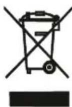
This marking indicates that this product should not be disposed with other household wastes throughout the EU. To prevent possible harm to the environment or human health from uncontrolled waste disposal, recycle it responsibly to promote the sustainable reuse of material resources. To return your used device, please use the return and collection systems or contact the retailer where the product was purchased. They can take this product for environmental safe recycling.
R32: 675
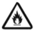
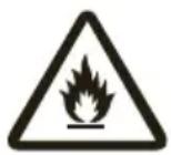
Appliance filled with flammable gas R32.
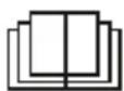
Before use the appliance, read the owner's manual first.

Before install the appliance, read the installation manual first.
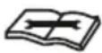
Before repair the appliance, read the service manual first.
The Refrigerant
- To realize the function of the air conditioner unit, a special refrigerant circulates in the system. The used refrigerant is the fluoride R32, which is specially cleaned.
The refrigerant is flammable and inodorous. Furthermore, it can leads to explosion under certain conditions. But the flammability of the refrigerant is very low. It can be ignited only by fire. - Compared to common refrigerants, R32 is a nonpolluting refrigerant with no harm to the ozonosphere. The influence upon the greenhouse effect is also lower. R32 has got very good thermodynamic features which lead to a really high energy efficiency. The units therefore need a less filling.
WARNING :
DO NOT use means to accelerate the defrosting process or to clean, other than those recommended by the manufacture. Should repair be necessary, contact your nearest authorized Service Center. Any repairs carried out by unqualified personnel may be dangerous. The appliance shall be stored in a room without continuously operating ignition sources. (for example: open flames, an operating gas appliance or an operating electric heater.) DO NOT pierce or burn.
Appliance shall be installed, operated and stored in a room with a floor area larger than 4m^2 .
Appliance filled with flammable gas R32. For repairs, strictly follow manufacturer's instructions only. Be aware that refrigrants not contain odour. Read specialist's manual.


Precautions
WARNING
Operation and Maintenance
- This appliance can be used by children aged from 8 years and above and persons with reduced physical, sensory ormental capabilities or lack of experience and knowledge if they have been given supervision or instruction concerning use of the appliance in a safe way and understand the hazards involved.
•Children shall not play with the appliance. - Cleaning and user maintenance shall not be made by children without supervision.
- DO NOT connect air conditioner to multi-purpose socket. Otherwise, it may cause fire hazard.
- Disconnect power supply when cleaning air conditioner. Otherwise, it may cause electric shock.
- If the supply cord is damaged, it must be replaced by the manufacturer, its service agent or similarly qualified persons in order to avoid a hazard.
- DO NOT wash the air conditioner with water to avoid electric shock.
- DO NOT spray water on indoor unit. It may cause electric shock or malfunction.
•After removing the filter, do not touch fins to avoid injury. - DO NOT use fire or hair dryer to dry the filter to avoid deformation or fire hazard.
Precautions

WARNING
- Maintenance must be performed by qualified professionals. Otherwise, it may cause personal injury or damage.
- DO NOT repair air conditioner by yourself. It may cause electric shock or damage. Please contact your dealer when you need to repair air conditioner.
- DO NOT insert fingers or objects into air inlet or air outlet. It may cause personal injury or damage.
- DO NOT block air outlet or air inlet. It may cause malfunction.
- DO NOT spill water on the remote controller, otherwise the remote controller may be broken.
- When below phenomenon occurs, please turn off air conditioner and disconnect power immediately, and then contact the dealer or qualified professionals for service.
• Power cord is overheating or damaged.
• There is abnormal sound during operation. - Circuit break trips off frequently.
• Air conditioner gives off burning smell.
• There is a leakage from the indoor unit. - If the air conditioner operates under abnormal conditions, it may cause malfunction, electric shock or fire hazard.
- When turning on or turning off the unit by emergency operation switch, please press this switch with an insulating object other than metal.
- DO NOT step on top panel of outdoor unit, or put heavy objects. It may cause damage or personal injury.
Precautions
WARNING
Attachment
•Installation must be performed by qualified professionals. Otherwise, it may cause personal injury or damage.
- Must follow the electric safety regulations when installing the unit.
- According to the local safety regulations, use qualified power supply circuit and circuit break.
• Install the circuit break. If not, it may cause malfunction.
- An all-pole disconnection switch having a contact separation of at least 3 mm in all poles should be connected in fixed wiring.
- Including an circuit break with suitable capacity, please note the following table. Air switch should be included magnet buckle and heating buckle function, it can protect the circuit-short and overload.
• Air conditioner should be properly grounded. Incorrect grounding may cause electric shock.
• DO NOT use unqualified power cord.
- Make sure the power supply matches with the requirement of air conditioner. Unstable power supply or incorrect wiring may result in electric shock, fire hazard or malfunction. Please install proper power supply cables before using the air conditioner.
- Properly connect the live wire, neutral wire and grounding wire of power socket.
Precautions

WARNING
- Be sure to cut off the power supply before proceeding any work related to electricity and safety.
- DO NOT put through the power before finishing installation.
- If the supply cord is damaged, it must be replaced by the manufacturer, its service agent or similarly qualified persons in order to avoid a hazard.
- The temperature of refrigerant circuit will be high, please keep the interconnection cable away from the copper tube.
- The appliance shall be installed in accordance with national wiring regulations.
- Installation must be performed in accordance with the requirement of NEC and CEC by authorized personnel only.
- The air conditioner is the first class electric appliance. It must be properly grounding with specialized grounding device by a professional. Please make sure it is always grounded effectively, otherwise it may cause electric shock.
- The yellow-green wire in air conditioner is grounding wire, which cannot be used for other purposes.
- The grounding resistance should comply with national electric safety regulations.
- The appliance must be positioned so that the plug is accessible.
- All wires of indoor unit and outdoor unit should be connected by a professional.
Precautions

WARNING
- If the length of power connection wire is insufficient, please contact the supplier for a new one. Avoid extending the wire by yourself.
- For the air conditioner with plug, the plug should be reachable after finishing installation.
- For the air conditioner without plug, an circuit break must be installed in the line.
- If you need to relocate the air conditioner to another place, only the qualified person can perform the work. Otherwise, it may cause personal injury or damage.
- Select a location which is out of reach for children and far away from animals or plants. If it is unavoidable, please add the fence for safety purpose.
- The indoor unit should be installed close to the wall.
- Instructions for installation and use of this product are provided by the manufacturer.
Precautions
WARNING
- The air conditioner is not allowed to use in a room that has running fire (such as fire source, working coal gas ware, operating heater).
- It is not allowed to drill hole or burn the connection pipe.
- The air conditioner must be installed in a room that is larger than the minimum room area. The minimum room area is shown on the nameplate or table a in page 39.
- Leak test is a must after installation.
- Instructions for installation and use of this product are provided by the manufacturer.
Working temperature range
| Indoor side DB/WB (°C) Outdoor side DB/WB ( ) °C | |
NOTICE:
- The operating temperature range (outdoor temperature) for cooling only unit is -15^ 43^ ; for heat pump unit is -15^ 43^ .
Parts Name
Indoor Unit
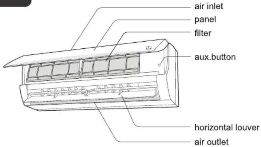
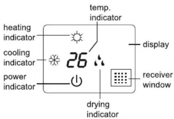
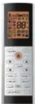
remote control
(Display content or position may be different from above graphics, please refer to actual products)
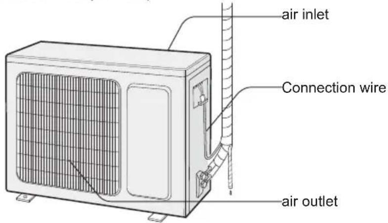
NOTICE:
Actual product may be different from above graphics, please refer to actual products.
Buttons on remote controller
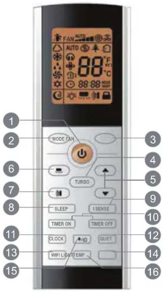
1 ON/OFF button
2 MODE button
3 FAN button
4 TURBO button
5 ▲/ ▼Button
6 Button
7 button
8 SLEEP button
9 I SENSE button
10 TIMER ON / TIMER OFF button
11 CLOCK button
12 QUIE T button
13 WIFI button
14 LIGHT button
15 ↘/button
16 TEMP button
Introduction for icons on display screen
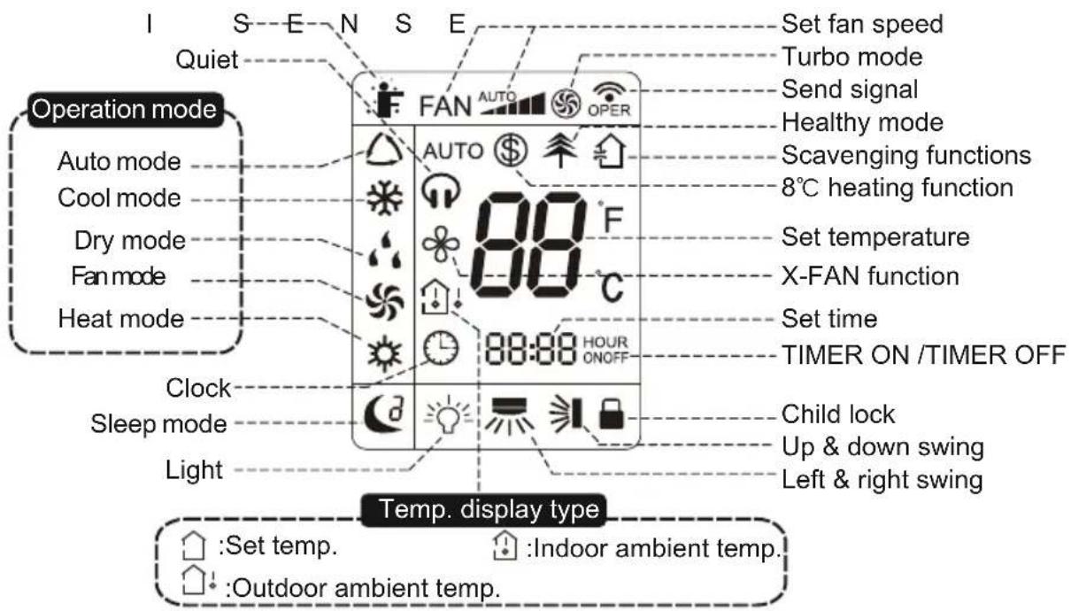
Introduction for buttons on remote controller
Note:
- This is a general use remote controller, it could be used for the air conditioners with multifunction; For some function, which the model does not have, if press the corresponding button on the remote controller that the unit will keep the original running status.
- After putting through the power, the air conditioner will give out a sound. Operation indicator "⏻" is ON (red indicator the colours different for different models). After that, you can operate the air conditioner by using remote controller.
- Under on status, pressing the button on the remote controller, the signal icon "💡" on the display of remote controller will blink once and the air conditioner will give out a "de" sound, which means the signal has been sent to the air conditioner.
1 ON/OFF button
Press this button to turn on the unit. Press this button again to turn off the unit.
2 MODE button
Press this button to select your required operation mode.

flowchart
graph LR
    A["△"] --> B["※"]
    B --> C["•"]
    C --> D["☀️"]
    D --> E["HE"]
- When selecting auto mode, air conditioner will operate automatically according to ex-factory setting. Set temperature cannot be adjusted and will not be displayed as well. Press "FAN" button can adjust fan speed. Press "☐" / "☐" button can adjust fan blowing angle.
- After selecting cool mode, air conditioner will operate under cool mode. Cool indicator "❄" on indoor unit is ON. Press "▲" or "▼" button to adjust set temperature. Press "FAN" button to adjust fan speed. Press "=" / "=" button to adjust fan blowing angle.
- When selecting dry mode, the air conditioner operates at low speed under dry mode. Dry indicator "⚡" on indoor unit is ON. Under dry mode, fan speed cannot be adjusted. Press "=" / "=" button to adjust fan blowing angle.
- When selecting fan mode, the air conditioner will only blow fan, no cooling and no heating. All indicators are OFF. Press "FAN" button to adjust fan speed. Press "☐" / "☐" button to adjust fan blowing angle.
- When selecting heating mode, the air conditioner operates under heat mode. Heat indicator "☀️" on indoor unit is ON. Press "▲" or "▼" button to adjust set temperature. Press "FAN" button to adjust fan speed. Press "☐" / "☒" button to adjust fan blowing angle. (Cooling only unit will not receive heating mode signal. If setting heat mode with remote controller, press ON/OFF button cannot start up the unit.)
Introduction for buttons on remote controller
Note:
- For preventing cold air, after starting up heating mode, indoor unit will delay 1\~5 minutes to blow air (actual delay time is depend on indoor ambient temperature).
- Set temperature range from remote controller: 16 - 30°C (61 - 86°F); Fan speed: auto, low speed, low-medium speed, medium speed, medium-high speed, high speed.
- Under auto mode, temperature can be displayed. Under auto mode, set temperature can be adjusted.
3 FAN button
This button is used for setting Fan Speed in the sequence that goes from AUTO, ▶,
to, then back to Auto.
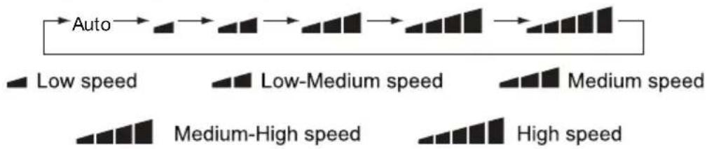
flowchart
graph LR
    A["Auto"] --> B["Low speed"]
    B --> C["Low-Medium speed"]
    C --> D["Medium speed"]
    D --> E["Medium-High speed"]
    E --> F["High speed"]
Note:
- It is Low fan speed under Dry mode.
- X-FAN function: Hold fan speed button for 2 seconds in COOL or DRY mode, the icon “✿” is displayed and the indoor fan will continue operation for a few minutes in order to dry the indoor unit even though you have turned off the unit. After energization, X-FAN OFF is defaulted. X-FAN is not available in AUTO, FAN or HEAT mode. This function indicates that moisture on evaporator of indoor unit will be blown after the unit is stopped to avoid mould.
• Having set X-FAN function on: After turning off the unit by pressing ON/OFF button indoor fan will continue running for a few minutes at low speed. In this period, hold fan speed button for 2 seconds to stop indoor fan directly.
- Having set X-FAN function off: After turning off the unit by pressing ON/OFF button, the complete unit will be off directly.
4 TURBO butto n
Under COOL or HEAT mode, press this button to turn to quick COOL or quick HEAT mode. " 🔊" icon is displayed on remote controller. Press this button again to exit turbo function and " 🔊" icon will disappear.
If start this function, the unit will run at super-highfan speed to cool or heat quickly so that the ambient temp. approaches the preset temp. as soon as possible.
Introduction for buttons on remote controller
5 ▲/▼ button
- Press "▲" or "▼" button once increase or decrease set temperature 1°C (°F). Holding "▲" or "▼" button, 2 seconds later, set temperature on remote controller will change quickly. On releasing button after setting is finished, temperature indicator on indoor unit will change accordingly. (Temperature cannot be adjusted under auto mode.)
- When setting TIMER ON, TIMER OFF or CLOCK, press "▲" or "▼" button to adjust time (Refer to CLOCK, TIMER ON, TIMER OFF buttons). When setting TIMER ON, TIMER OFF or CLOCK, press "▲" or "▼" button to adjust time (Refer to CLOCK, TIMER ON, TIMER OFF buttons).
6 button (not available)
Press this button can select left and right swing angle. Fan blow angle can be selected circularly as below:

flowchart
graph TD
    A["Start"] --> B["Display"]
    B --> C["Display"]
    C --> D["Display"]
    D --> E["Display"]
    E --> F["Display"]
    F --> G["Display"]
    G --> H["Display"]
    H --> I["Display"]
    I --> J["Display"]
    J --> K["Display"]
    K --> L["Display"]
    L --> M["Display"]
    M --> N["Display"]
    N --> O["Display"]
    O --> P["Display"]
    P --> Q["Display"]
    Q --> R["Display"]
    R --> S["Display"]
    S --> T["Display"]
    T --> U["Display"]
    U --> V["Display"]
    V --> W["Display"]
    W --> X["Display"]
    X --> Y["Display"]
    Y --> Z["Display"]
    Z --> AA["Display"]
    AA --> AB["Display"]
    AB --> AC["Display"]
    AC --> AD["Display"]
    AD --> AE["Display"]
    AE --> AF["Display"]
    AF --> AG["Display"]
    AG --> AH["Display"]
    AH --> AI["Display"]
    AI --> AJ["Display"]
    AJ --> AK["Display"]
    AK --> AL["Display"]
    AL --> AM["Display"]
    AM --> AN["Display"]
    AN --> AO["Display"]
    AO --> AP["Display"]
    AP --> AQ["Display"]
    AQ --> AR["Display"]
    AR --> AS["Display"]
Note:
- Press this button continuously more than 2 seconds, the main unit will swing back and forth from left to right, and then loosen the button, the unit will stop swinging and present position of guide louver will be kept immediately.
- Under swing left and right mode, when the status is switched from off to ☐, if press this button again 2 seconds later ☐ status will switch to off status directly; if press this button again within 2 seconds, the change of swing status will also depend on the circulation sequence stated above.
7 button
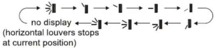
Press this button can select up and down swing angle. Fan blow angle can be selected circularly as below:
flowchart
graph LR
    A["->"] --> B["->"] --> C["->"] --> D["-"] --> E["->"]
    F["no display"] <--_G["->"] <--_H["->"] <--_I["->"]
    style A fill:#f9f,stroke:#333
    style B fill:#f9f,stroke:#333
    style C fill:#f9f,stroke:#333
    style D fill:#f9f,stroke:#333
    style E fill:#f9f,stroke:#333
    style F fill:#f9f,stroke:#333
    note right of F (horizontal louvers stops at current position)
- When selecting "→", air conditioner is blowing fan automatically. Horizontal louver will automatically swing up and down at maximum angle.
- When selecting "I、II、-I、J、I",air conditioner is blowing fan at fixed position. Horizontal louver will stop at the fixed position.
- When selecting " ≥slant |、 ≥slant ||、 ≥slant ||", air conditioner is blowing fan at fixed angle. Horizontal louver will send air at the fixed angle.
- Hold “→” button above 2 seconds to set your required swing angle. When reaching your required angle, release the button.
Introduction for buttons on remote controller
Note:
- "≥|、≥|、≥|" may not be available. When air conditioner receives this signal, the air conditioner will blow fan automatically.
- Press this button continuously more than 2 seconds, the main unit will swing back and forth from up to down, and then loosen the button, the unit will stop swinging and present position of guide louver will be kept immediately.
- Under swing up and down mode, when the status is switched from of press this button again 2 seconds later, status will switch to off status directly; if press this button again within 2 seconds, the change of swing status will also depend on the circulation sequence stated above.
8 SLEEP button
In the Cooling or Heating mode, press this button to start sleep mode. Once you set it up, this symbol “C” appears on the screen remote control. Sleep Mode has three places to choose from, Sleep Mode 1, Sleep Mode 2, Sleep Mode 3. To navigate through the options, press the sleep button. By pressing it once Sleep Mode 1 “C” will be activated, by pressing it twice Sleep Mode 2 “C” activates, three times Sleep Mode 3 “C” activates. Pressing the button for the fourth time will disable this function and “will disappear. If you deactivate the air conditioner, sleep mode will be deactivated. During DRY, FAN, AUTO, Energy Saving & “8°C Heating” functions, sleep mode is not available.
Sleep Mode 1
Sleep Mode 1 “C” is available in Cooling or Heating mode. By activating this function, the air conditioner’s temperature increases by one degree per hour in “Cooling” mode and decreases by one degree per hour in “Heating” mode.
Sleep Mode 2
Sleep mode 2 “C” will only be activated during Cooling or Heating mode.
During Cooling mode:
-If the air conditioner temperature is set between 16 - 23°C, the temperature will increase by one degree per hour for the next 3 hours after the power is turned on and then remains stable. At the 8th hour after the operation is switched on, the temperature will be reduced by one degree automatically.
-If the air conditioner temperature is set between 24 - 27°C, the temperature will increase by one degree per hour for the next 2 hours from the start of the operation and then remain stable. At the 8th hour after the operation is switched on, the temperature will be reduced by one degree automatically.
-If the air conditioner temperature is set between 28 - 29°C, the temperature will increase to a certain degree within the next hour of activation and then remain stable. At the 8th hour after the operation is switched on, the temperature will be reduced by one degree automatically.
-If the air conditioner temperature is set from 30^ to above, it will remain constant for 7 hours after the operation is switched on and at 8 o'clock the temperature will be reduced by one degree automatically.
During Heating mode:
-If the air conditioner selection is 16^ C, the air conditioner will continue to operate at this temperature.
-If the air conditioner temperature is between 17^ and 20^ , the air conditioner's temperature will drop to a certain extent after the first hour of the operation and then remain constant.
-If the air conditioner's temperature is between 21 - 27°C, the air conditioner's temperature will drop by one degree per hour within the first 2 hours of activation and then remain constant.
-If the air conditioner's temperature is between 28 - 30°C, the air conditioner's temperature will be reduced by one degree per hour in the first 3 hours after activation and then will remain constant.
Sleep Mode 3
Sleep Mode 3 “3” is available in Cooling or Heating modes. By activating this function, you can create your own personalized program based on time and temperature. To set the time and temperature, press the “TURBO” button for 3 seconds, and the temperature icon will flash on the remote-control screen.

You can set the temperature by hour, up to 8 hours continuously. With the “▲” and “▼” buttons you can adjust and change the temperature. To confirm the desired temperature, press the “TURBO” button. To set the temperature for the second hour repeat the same procedure.
The personalized program is stored in the memory despite the deactivation of the air conditioner.
Introduction for buttons on remote controller
9 I SENSE button
Press this button to start I SENSE function and "F" will be displayed on the remote controller. After this function is set, the remote controller will send the detected ambient temperature to the controller and the unit will automatically adjust the indoor temperature according to the detected temperature. Press this button again to close I SENSE function and "F" will disappear.
- Please put the remote controller near user when this function is set. Do not put the remote controller near the object of high temperature or low temperature in order to avoid detecting inaccurate ambient temperature.
When I SENSE function is turned on, the remote controller should be put within the area where indoor unit can receive the signal sent by the remote controller.
10 TIMER ON / TIMER OFF button
- TIMER ON button
"TIMER ON" button can set the time for timer on. After pressing this button, "💡" icon disappears and the word "ON" on remote controller blinks. Press "▲" or "▼" button to adjust TIMER ON setting. After each pressing "▲" or "▼" button, TIMER ON setting will increase or decrease 1 minute. Hold "▲" or "▼" button, 2 seconds later, the time will change quickly until reaching your required time. Press "TIMER ON" to confirm it. The word "ON" will stop blinking. "💡" icon resumes displaying. Cancel TIMER ON: Under the condition that TIMER ON is started up, press "TIMER ON" button to cancel it.
- TIMER OFF button
"TIMER OFF" button can set the time for timer off. After pressing this button, " ℓ " icon disappears and the word "OFF" on remote controller blinks. Press "▲" or "▼" button to adjust TIMER OFF setting. After each pressing "▲" or "▼" button, TIMER OFF setting will increase or decrease 1 minute. Hold "▲" or "▼" button, 2 seconds later, the time will change quickly until reaching your required time. Press "TIMER OFF" word "OFF" will stop blinking. " ℓ " icon resumes displaying. Cancel TIMER OFF. Under the condition that TIMER OFF is started up, press "TIMER OFF" button to cancel it.
Introduction for buttons on remote controller
Note:
- Under on and off status, you can set TIMER OFF or TIMER ON simultaneously.
- Before setting TIMER ON or TIMER OFF, please adjust the clock time.
- After starting up TIMER ON or TIMER OFF, set the constant circulating valid. After that, air conditioner will be turned on or turned off according to setting time. ON/OFF button has no effect on setting. If you do not need this function, please use remote controller to cancel it.
11 CLOCK button
Press this button to set clock time. "💡" icon on remote controller will blink. Press "▲" or "▼" button within 5 seconds to set clock time. Each pressing of "▲" or "▼" button clock time will increase or decrease 1 minute. If hold "▲" or "▼" button, 2 seconds later, time will change quickly. Release this button when reaching your required time. Press "CLOCK" button to confirm the time. "💡" icon stops blinking.
Note:
- Clock time adopts 24-hour mode.
- The interval between two operation cannot exceeds 5 seconds. Otherwise, remote controller will quit setting status. Operation for TIMER ON/TIMER OFF is the same.
12 QUIET button
Press this button, the Quiet status is under the Auto Quiet mode (display " ", " and "AUTO" signal ) and Quiet mode (display " ", " singal) and Quiet OFF (there is no signal of " ", " displayed), after powered on, the Quiet OFF is defaulted.
Note:
- The Quiet function cannot be set up in Fan and Dry mode; Under the Quiet mode, the fan speed is not available.
- When quiet function is selected
Under cooling mode: indoor fan operates at notch 4 speed. 10 minutes later or when indoor ambient temperature ≥ 28^ , indoor fan will operate at notch 2 speed or quiet mode according to the comparison between indoor ambinet temperature and set temperature.
Under heating mode: indoor fan operates at notch 3 speed or quiet mode according to the comparison between indoor ambient temperature and set temperature.
Under dry, fan mode: indoor fan operates at quiet mode.
Under auto mode: the indoor fan operates at the auto quiet mode according to actual cooling, heating or fan mode.
- The Quiet function is only available for some models.
13 Wi-Fi button
Press "WiFi" button to turn on or turn off WiFi function. When WiFi function is turned on, the "WiFi" icon will be displayed on remote controller; Under status of remote controller off, press "MODE" and "WiFi" buttons simultaneously for 1 second, WiFi module will restore to factory default setting.
- This function is only available for some models.
Introduction for buttons on remote controller
14 LIGHT button
Press this button to turn off display light on indoor unit. "💡" icon on remote controller disappears. Press this button again to turn on display light. "💡" icon is displayed.
15 / button
Press this button to achieve the on and off of healthy and scavenging functions in operation status. Press this button for the first time to start scavenging function; LCD displays "✗" (not available). Press the button for the second time to start healthy and scavenging functions simultaneously; LCD displays "✗" and "✗". Press this button for the third time to quit healthy and scavenging functions simultaneously.
Press the button for the fourth time to start healthy function; LCD display "↑". Press this button again to repeat the operation above.
16 TEMP button
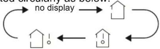
By pressing this button, you can see indoor set temperature, indoor ambient temperature or outdoor ambient temperature on indoor unit's display. The setting on remote controller is selected circularly as below:
flowchart
graph TD
    A["House Icon"] --> B["House Icon"]
    B --> C["House Icon"]
    C --> D["House Icon"]
    D --> A
    style A fill:#f9f,stroke:#333
    style B fill:#ccf,stroke:#333
    style C fill:#cfc,stroke:#333
- When selecting "☐" or no display with remote controller, temperature indicator on indoor unit displays set temperature.
- When selecting " 🔊" with remote controller, temperature indicator on indoor unit displays indoor ambient temperature.
- When selecting "☐!" with remote controller, temperature indicator on indoor unit displays outdoor ambient temperature (not available).
Note:
- Outdoor temperature display is not available for some models. At that time, indoor unit receives " 🔊!" signal, while it displays indoor set temperature.
- It's defaulted to display set temperature when turning on the unit. There is no display in the remote controller.
- Only for the models whose indoor unit has dual-8 display.
- When selecting displaying of indoor or outdoor ambient temperature, indoor temperature indicator displays corresponding temperature and automatically turn to display set temperature after three or five seconds.
Function introduction for combination buttons
Energy-saving function
Under cooling mode, press "TEMP" and "CLOCK" buttons simultaneously to start up or turn off energy-saving function. When energy-saving function is started up, "SE" will be shown on remote controller, and air conditioner will adjust the set temperature automatically according to ex-factory setting to reach to the best energy-saving effect. Press "TEMP" and "CLOCK" buttons simultaneously again to exit energy-saving function.
Note:
- Under energy-saving function, fan speed is defaulted at auto speed and it cannot be adjusted.
- Under energy-saving function, set temperature cannot be adjusted. Press "TURBO" button and the remote controller will not send signal.
- Sleep function and energy-saving function cannot operate at the same time. If energy-saving function has been set under cooling mode, press sleep button will cancel energy-saving function. If sleep function has been set under cooling mode, start up the energy-saving function will cancel sleep function.
8° cheating function
Under heating mode, press "TEMP" and "CLOCK" buttons simultaneously to start up or turn off 8°C heating function. When this function is started up, " \$ and "8 °C will be shown on remote controller, and the air conditioner keep the heating status at 8°C . Press "TEMP" and "CLOCK" buttons simultaneously again to exit 8°C heating function.
Note:
- Under 8°C heating function, fan speed is defaulted at auto speed and it cannot be adjusted.
- Under 8°C heating function, set temperature cannot be adjusted. Press "TURBO" button and the remote controller will not send signal.
- Sleep function and 8°C heating function cannot operate at the same time. If 8°C heating function has been set under cooling mode, press sleep button will cancel 8°C heating function. If sleep function has been set under cooling mode, start up the 8°C heating function will cancel sleep function.
- Under °F temperature display, the remote controller will display 46 °heating.
Child lock function
Press "▲" and "▼" simultaneously to turn on or turn off child lock function. When child lock function is on, "☐" icon is displayed on remote controller. If you operate the remote controller, the "☐" icon will blink three times without sending signal to the unit.
Temperature display switchover function
Under OFF status, press "▼" and "MODE" buttons simultaneously to switch temperature display between °C and °F
Operation guide
- After putting through the power, press "ON/OFF" button on remote controller to turn on the air conditioner.
- Press "MODE" button to select your required mode: AUTO, COOL, DRY, FAN, HEAT.
- Press “▲” or “▼” button to set your required temperature (Temperature cannot be adjusted under auto mode).
- Press "FAN" button to set your required fan speed: auto, low, medium and high speed.
- Press "SWING" button to select fan blowing angle.
Replacement of batteries in remote controller
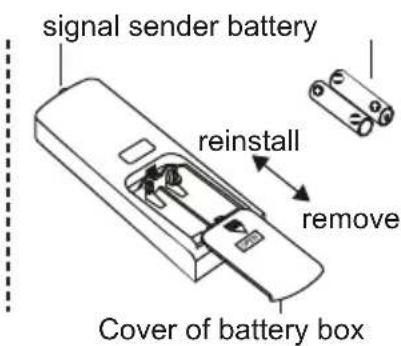
- Press the back side of remote controller marked with " ", as shown in the fig, and then push out the cover of battery box along the arrow direction.
- Replace two 7# (AAA 1.5V) dry batteries, and make sure the position of "+" polar and "-" polar are correct.
- Reinstall the cover of battery box.
NOTICE
- During operation, point the remote control signal sender at the receiving window on indoor unit.
- The distance between signal sender and receiving window should be no more than 8 m, and there should be no obstacles between them.
- Signal may be interfered easily in the room where there is fluorescent lamp or wireless telephone; remote controller should be close to indoor unit during operation.
- Replace new batteries of the same model when replacement is required.
- When you do not use remote controller for a long time, please take out the batteries.
- If the display on remote controller is fuzzy or there is no display, please replace batteries.
Emergency operation
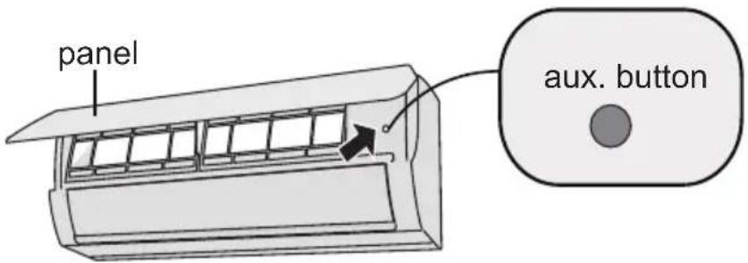
If remote controller is lost or damaged, please use auxiliary button to turn on or turn off the air conditioner. The operation in details are as below: As shown in the fig. Open panel, press aux. button to turn on or turn off the air conditioner. When the air conditioner is turned on, it will operate under auto mode.
WARNING:
Use insulated object to press the auto button.
Clean and maintenance
WARNING
■ Turn off the air conditioner and disconnect the power before cleaning the air conditioner to avoid electric shock.
■ DO NOT wash the air conditioner with water to avoid electric shock.
■ DO NOT use volatile liquid to clean the air conditioner.
Clean surface of indoor unit
When the surface of indoor unit is dirty, it is recommended to use a soft dry cloth or wet cloth to wipe it.
NOTICE:
- Do not remove the panel when cleaning it.
Clean and Maintenance
Clean filter
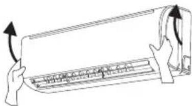
1 Open panel
Pull out the panel to a certain angle as shown in the fig.
natural_image
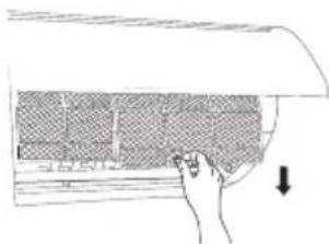
Diagram of hands holding a curved object with directional arrows indicating motion (no text or symbols)2 Remove filter
Remove the filter as in- dicated in the fig.
natural_image
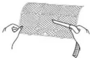
Hand placing a grid on a curved surface with an arrow indicating downward motion (no text or symbols)3 Clean filter
- Use dust catcher or water to clean the filter.
- When the filter is very dirty, use the water (below 45°C) to clean it, and then put it in a shady and cool place to dry.
natural_image
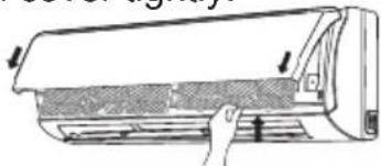
Diagram of a band being cut with scissors, showing mesh texture and force application (no text or symbols)4 Install filter
Install the filter and then close the panel cover tightly.
natural_image
Diagram of a car air conditioner unit with airflow direction arrows (no text or labels)
WARNING
■ The filter should be cleaned every three months. If there is much dust in the operation environment, clean frequency can be increased.
■ After removing the filter, do not touch fins to avoid injury.
■ DO NOT use fire or hair dryer to dry the filter to avoid deformation or fire hazard.
Clean and Maintenance
Checking before use-season
- Check whether air inlets and air outlets are blocked.
- Check whether air switch, plug and socket are in good condition.
- Check whether filter is clean.
- Check whether mounting bracket for outdoor unit is damaged or corroded. If yes, please contact dealer.
- Check whether drainage pipe is damaged.
Checking after use-season
- Disconnect power supply.
- Clean filter and indoor unit's panel.
- Check whether mounting bracket for outdoor unit is damaged or corroded. If yes, please contact dealer.
Notice for recovery
- Many packing materials are recyclable materials.
Please dispose them in appropriate recycling unit. - If you want to dispose the air conditioner, please contact local dealer or consultant service center for the correct disposal method.
Malfunction analysis
General phenomenon analysis
Please check below items before asking for maintenance. If the malfunction still cannot be eliminated, please contact local dealer or qualified professionals.
| noituloSsme | ||
| Indoor unit cannot receive remote controller's signal or remote controller has no action. | Whether it is interfered severely (such as static electricity, stable voltage)? | Pull out the plug. Reinsert the plug after about 3 minutes, and then turn on the unit again. |
| Whether remote controller is within the signal receiving range? | Signal receiving range is 8 m. | |
| Whether there are obstacles? | Remove obstacles. | |
| Whether remote controller is pointing at the receiving window? | Select proper angle and point the remote controller at the receiving window on indoor unit. | |
| Is sensitivity of remote controller low; fuzzy display and no display? | Check the batteries. If the power of batteries is too low, please replace them. | |
| No display when operating remote controller? | Check whether remote controller appears to be damaged. If yes, replace it. | |
| Fluorescent lamp in room? | Take the remote controller close to indoor unit.Turn off the fluorescent lamp and then try it again. |
| No air emitted from indoor unit. | ● Air inlet or air outlet of indoor unit is blocked? | ● Eliminate obstacles. |
| ● Under heating mode, indoor temperature is reached to set temperature? | ● After reaching to set temperature, indoor unit will stop blowing out air. | |
| ● Heating mode is turned on just now? | ● In order to prevent blowing out cold air, indoor unit will be started after delaying for several minutes, which is a normal phenomenon. |
Malfunction analysis
| noituloSsme | ||
| Air conditioner cannot operate | Power failure? | Wait until power recovery. |
| Is plug loose? | Reinsert the plug. | |
| Air switch trips off or fuse is burnt out? | Ask professional to replace air switch or fuse. | |
| Wiring has malfunction? | Ask professional to replace it. | |
| Unit has restarted immediately after stopping operation? | Wait for 3 minutes, and then turn on the unit again. | |
| Whether the function setting for remote controller is correct? | Reset the function. |
| Mist is emitted from indoor unit's air outlet | • Indoor temperature and humidity is high? | • Because indoor air is cooled rapidly. After a while, indoor temperature and humidity will be decrease and mist will disappear. |
| Set temperature cannot be adjusted | Unit is operating under auto mode? | Temperature cannot be adjusted under auto mode.Please switch the operation mode if you need to adjust temperature. |
| Your required temperature exceeds the set temperature range? | Set temperature range: 16°C ~30°C . |
| Cooling (heating) effect is not good. | Voltage is too low? | Wait until the voltage resumes normal. |
| Filter is dirty? | Clean the filter. | |
| Set temperature is in proper range? | Adjust temperature to proper range. | |
| Door and window are open? | Close door and window. |
Malfunction analysis
| noituloSsmeti kce |
| Odours are emitted | Whether there is odour source, such as furniture and cigarette, etc. | Eliminate the odour source.Clean the filter. |
| Air conditioner operates abnormally | ● Whether there is interference, such as thunder, wireless devices, etc. | ● Disconnect power, put back power, and then turn on the unit again. |
| Outdoor unit has vapor | • Heating mode is turned on? | • During defrosting under heating mode, it may generate vapor, which is a normal phenomenon. |
| “Water flowing” noise | • Air conditioner is turned on or turned off just now? | • The noise is the sound of refrigerant flowing inside the unit, which is a normal phenomenon. |
| Cracking noise | • Air conditioner is turned on or turned off just now? | • This is the sound of friction caused by expansion and/or contraction of panel or other parts due to the change of temperature. |
Malfunction analysis
Error Code
- When air conditioner status is abnormal, temperature indicator on indoor unit will blink to display corresponding error code. Please refer to below list for identification of error code.
| Error code | Troubleshooting |
| E5 | It can be eliminated after restarting the unit. If not, please contact qualified professionals for service. |
| E8 | It can be eliminated after restarting the unit. If not, please contact qualified professionals for service. |
| U8 | It can be eliminated after restarting the unit. If not, please contact qualified professionals for service. |
| H6 | It can be eliminated after restarting the unit. If not, please contact qualified professionals for service. |
| C5 | Please contact qualified professionals for service. |
| F1 | Please contact qualified professionals for service. |
| F2 | Please contact qualified professionals for service. |
| H3 | It can be eliminated after restarting the unit. If not, please contact qualified professionals for service. |
| F4 | Please contact qualified professionals for service. |
| F0 | Please contact qualified professionals for service. |
Note: If there are other error codes, please contact qualified professionals for service.

WARNING
■ When below phenomenon occurs, please turn off air conditioner and disconnect power immediately, and then contact the dealer or qualified professionals for service.
- Power cord is overheating or damaged.
- There is abnormal sound during operation.
• Air switch trips off frequently.
• Air conditioner gives off burning smell.
• There is a leakage from the indoor unit.
■ DO NOT repair or refit the air conditioner by yourself.
■ If the air conditioner operates under abnormal conditions, it may cause malfunction, electric shock or fire hazard.
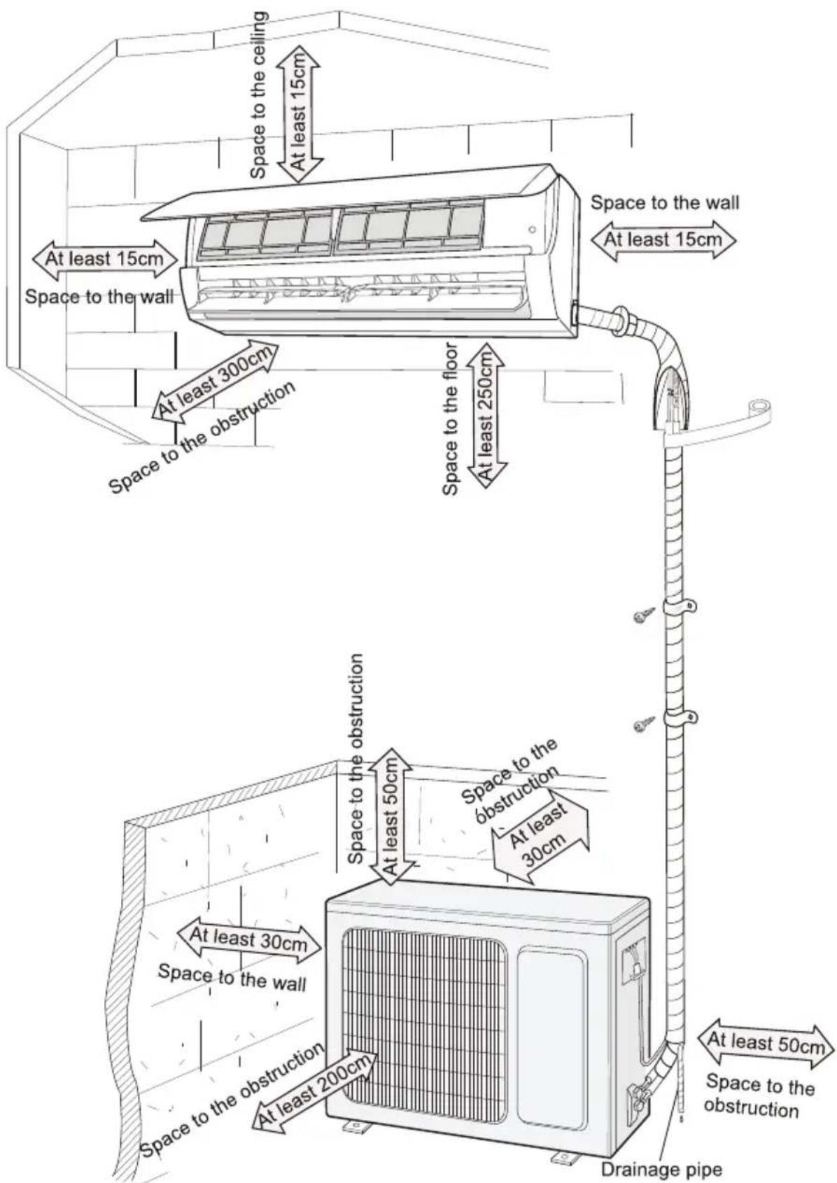
Installation dimension diagram
Tools for installation
| 1 Level meter 2 Screw driver 3 Impact drill | ||
| 4 Drill head 5 Pipe expander 6 Torque wrench | ||
| 7 Open-end wrench 8 Pipe cutter 9 Leakage detector | ||
| 10 Vacuum pump 11 Pressure meter 12 Universal meter | ||
| 13 Inner hexagon spanner 14 Measuring tape | ||
Note: Please contact the local agent for installation.
- Do not use unqualified power cord.
Selection of installation location
| Basic requirementInstalling the unit in the following places may cause malfunction. If it is unavoidable, please consult the local dealer:1.The place with strong heat sources, vapors, flammable or explosive gas, or volatile objects spread in the air.2.The place with high-frequency devices (such as welding machine, medical equipment).3.The place near coast area.4.The place with oil or fumes in the air.5.The place with sulfureted gas.6.Other places with special circumstances.7.The appliance shall not be installed in the laundry. | Indoor unit1.There should be no obstruction near air inlet and air outlet.2.Select a location where the condensation water can be dispersed easily and will not affect other people.3.Select a location which is convenient to connect the outdoor unit and near the power socket.4.Select a location which is out of reach for children.5.The location should be able to with stand the weight of indoor unit and will not increase noise and vibration.6.The appliance must be installed 2.5 m above floor.7.Do not install the indoor unit right above the electric appliance.8.Please try your best to keep way from fluorescent lamp. |
| Outdoor unit1.Select a location where the noise and outflow air emitted by the outdoor unit will not affect neighborhood.2.The location should be well ventilated and dry, in which the outdoor unit will not be exposed directly to sunlight or strong wind.3.The location should be able to withstand the weight of outdoor unit.4.Make sure that the installation follows the requirement of installation dimension diagram.5.Select a location which is out of reach for children and far away from animals or plants. If it is unavoidable, please add the fence for safety purpose. | |
Requirements for electric connection
Safety precaution
- Must follow the electric safety regulations when installing the unit.
- According to the local safety regulations, use qualified power supply circuit and air switch.
-
Make sure the power supply matches with the requirement of air conditioner. Unstable power supply or incorrect wiring or malfunction. Please install proper power supply cables before using the air conditioner.
-
Properly connect the live wire, neutral wire and grounding wire of power socket.
-
Be sure to cut off the power supply before proceeding any work related to electricity and safety.
-
Do not put through the power before finishing installation.
-
If the supply cord is damaged, it must be replaced by the manufacturer, its service agent or similarly qualified persons in order to avoid a hazard.
-
The temperature of refrigerant circuit will be high, please keep the interconnection cable away from the copper tube.
-
The appliance shall be installed in accordance with national wiring regulations.
-
Appliance shall be installed, operated and stored in a room with a floor area larger than 4m^2 .
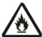
Please notice that the unit is filled with flammable gas R32. Inappropriate treatment of the unit involves the risk of severe damages of people and material. Details to this refrigerant are found in chapter “refrigerant”.
Grounding requirement
- The air conditioner is the first class electric appliance. It must be properly grounding with specialized grounding device by a professional. Please make sure it is always grounded effectively, otherwise it may cause electric shock.
- The yellow-green wire in air conditioner is grounding wire, which cannot be used for other purposes.
- The grounding resistance should comply with national electric safety regulations.
- The appliance must be positioned so that the plug is accessible.
- An all-pole disconnection switch having a contact separation of at least 3 mm in all poles should be connected in fixed wiring.
- Including an air switch with suitable capacity, please note the following table. Air switch should be included magnet buckle and heating buckle function, it can protect the circuit-short and overload. (Caution: please do not use the fuse only for protect the circuit.)
| Air-conditioner | Air switch capacity |
| 9K & 12K | 10A |
| 16A18K | |
| 24K | 25A |
Installation of indoor unit
Step one: choosing installation location
Recommend the installation location to the client and then confirm it with the client.
Step two: install wall-mounting frame
- Hang the wall-mounting frame on the wall; adjust it in horizontal position with the level meter and then point out the screw fixing holes on the wall.
- Drill the screw fixing holes on the wall with impact drill (the specification of drill head should be the same as the plastic expansion particle) and then fill the plastic expansion particles in the holes.
- Fix the wall-mounting frame on the wall with tapping screws (ST4.2X25TA) and then check if the frame is firmly installed by pulling the frame. If the plastic expansion particle is loose, please drill another fixing hole nearby.
Step three: open piping hole
- Choose the position of piping hole according to the direction of outlet pipe. The position of piping hole should be a little lower than the wall-mounted frame, shown as below.
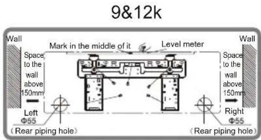
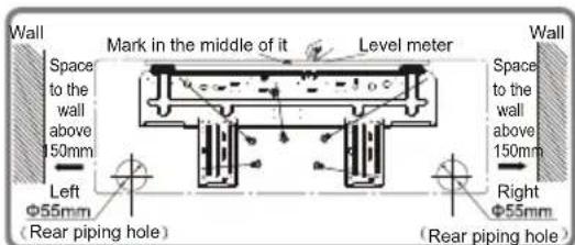
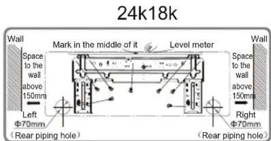
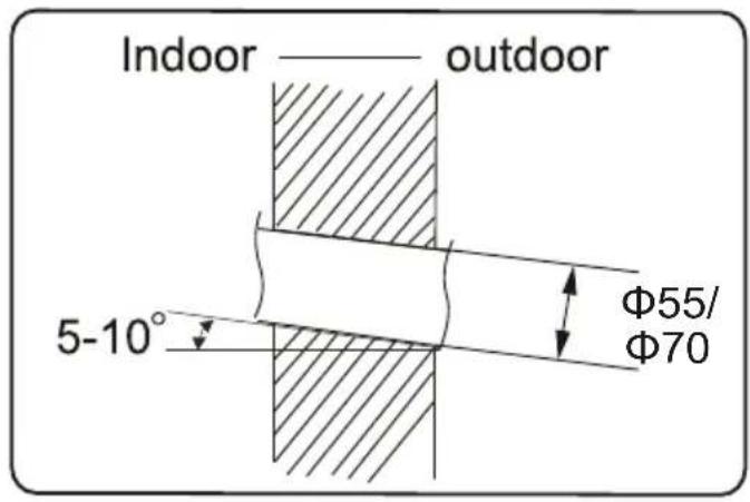
- Open a piping hole with the diameter of 65 or 70 on the selected outlet pipe position. In order to drain smoothly, slant the piping hole on the wall slightly downward to the outdoor side with the gradient of 5 - 10°.
Installation of indoor unit
Note:
- Pay attention to dust prevention and take relevant safety measures when opening the hole.
- The plastic expansion particles are not provided and should be bought locally.
Step four: outlet pipe
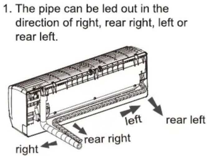
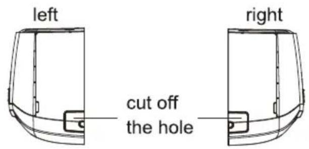
- When select leading out the pipe from left or right, please cut off the corresponding hole on the bottom case.
Step five: connect the pipe of indoor unit
-
Aim the pipe joint at the corresponding bellmouth.
-
Pretightening the union nut with hand.
-
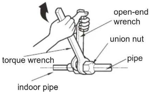
Adjust the torque force by referring to the following sheet. Place the open-end wrench on the pipe joint and place the torque wrench on the union nut. Tighten the union nut with torque wrench.
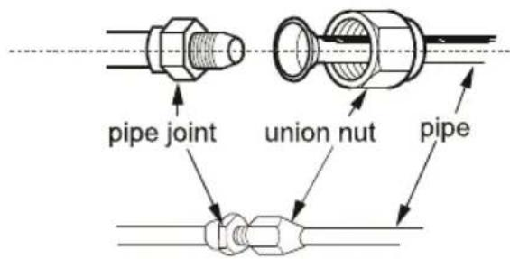
Installation of indoor unit
- Wrap the indoor pipe and joint of connection pipe with insulating pipe, and then wrap it with tape.
| Hex nut diameter | Tightening torque (N ·m) |
| Φ 6 | 15~20 |
| Φ 9.52 | 30~40 |
| Φ 12 | 45~55 |
| Φ 16 | 60~65 |
| Φ 19 | 70~75 |
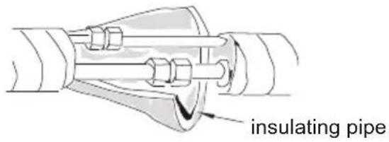
Step six: install drain hose
-
Connect the drain hose to the outlet pipe of indoor unit.
-
Bind the joint with tape.
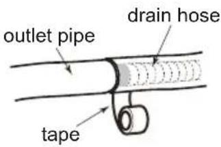
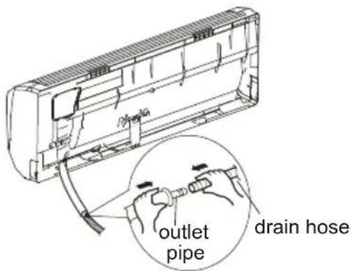
Note:
- Add insulating pipe in the indoor drain hose in order to prevent condensation.
- The plastic expansion particles are not provided.
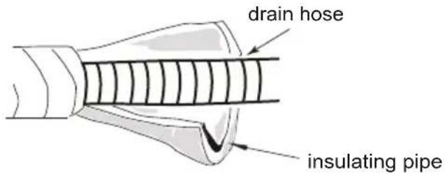
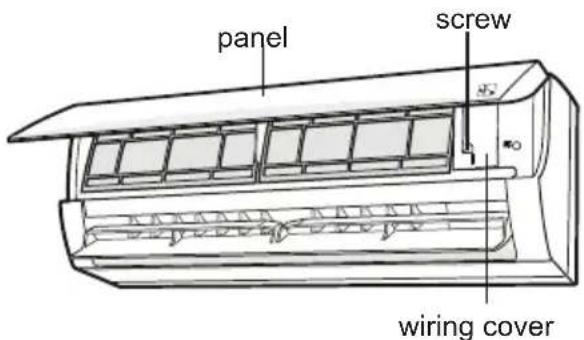
Step seven: connect wire of indoor unit
- Open the panel, remove the screw on the wiring cover and then take down the cover.
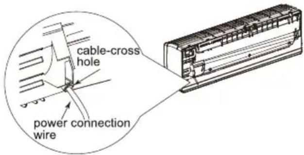
Installation of indoor unit
-
Make the power connection wire go through the cable-cross hole at the back of indoor unit and then pull it out from the front side.
-
Remove the wire clip; connect the power connection wire to the wiring terminal according to the color; tighten the screw and then fix the power connection wire with wire clip.
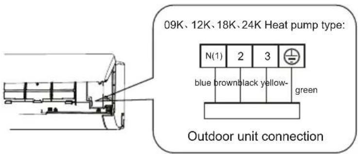
Note: The wiring board is for reference only. Please refer to the actual one.
- Put wiring cover back and then tighten the screw.
- Close the panel.
Note:
- All wires of indoor unit and outdoor unit should be connected by a professional.
- If the length of power connection wire is insufficient, please contact the supplier for a new one. Avoid extending the wire by yourself.
- For the air conditioner with plug, the plug should be reachable after finishing installation.
- For the air conditioner without plug, an air switch must be installed in the line. The air switch should be all-pole parting and the contact parting distance should be more than 3 mm.
Installation of indoor unit
Step eight: bind up pipe
- Bind up the connection pipe, power cord and drain hose with the band.
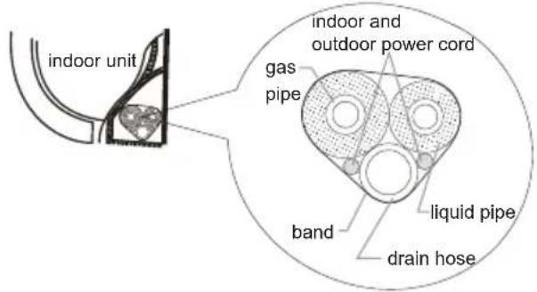
- Reserve a certain length of drain hose and power cord for installation when binding them. When binding to a certain degree, separate the indoor power and then separate the drain hose.
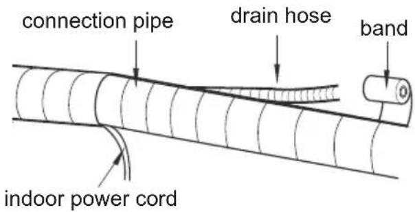
-
Bind them evenly.
-
The liquid pipe and gas pipe should be bound separately at the end.
Note:
- The power cord and control wire cannot be crossed or winding.
- The drain hose should be bound at the bottom.
Step nine: hang the indoor unit
- Put the bound pipes in the wall pipe and then make them pass through the wall hole.
- Hang the indoor unit on the wall-mounting frame.
- Stuff the gap between pipes and wall hole with sealing gum.
- Fix the wall pipe.
- Check if the indoor unit is installed firmly and closed to the wall.
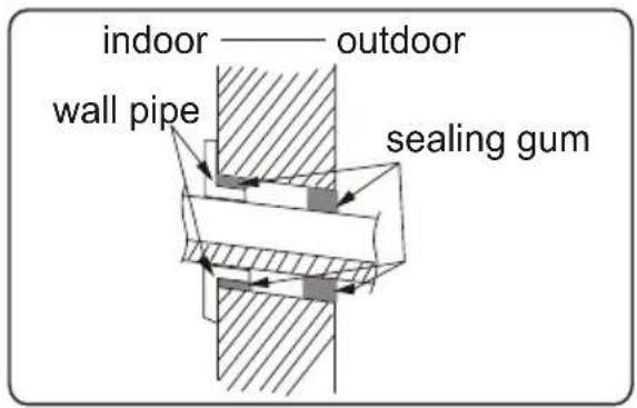
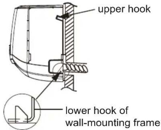
Note:
- Do not bend the drain hose too excessively in order to prevent blocking.
Configuration of connection pipe
- Standard length of connection pipe
- 5 m, 7.5 m, 8 m.
- Min. length of connection pipe is 3 m.
3.Max. length of connection pipe
| Cooling capacity capacity | Max length of connec-tion pipe |
| 5000Btu/h (1465W) | 15 |
| 7000Btu/h (2051W) | 15 |
| 9000Btu/h (2637W) | 15 |
| 12000Btu/h (3516W) | 20 |
| 18000Btu/h (5274W) | 25 |
| Cooling | Max length of connection pipe |
| 24000Btu/h (7032W) | 25 |
| 28000Btu/h (8204W) | 30 |
| 36000Btu/h (10548W) | 30 |
| 42000Btu/h (12306W) | 30 |
| 48000Btu/h (14064W) | 30 |
- The additional refrigerant oil and refrigerant charging required after prolonging connection pipe.
After the length of connection pipe is prolonged for 10 m at the basis of standard length, you should add 5 ml of refrigerant oil for each additional 5 m of connection pipe.
The calculation method of additional refrigerant charging count (on the axis of liquid pipe):
- Additional refrigerant charging amount = prolonged length of liquid pipe × additional refrigerant charging amount per meter
- Basing on the length of standard pipe, add refrigerant according to the requirement as shown in the table. The additional refrigerant charging amount per meter is different according to the diameter of liquid pipe. See the following sheet.
Configuration of connection pipe
Sheet 2. Additional refrigerant charging amount for R32
| Diameter of connection pipe mm | Indoor unit throttle | Outdoor unit throttle | ||
| Liquid pipe Gas pipe | Cooling only, cooling and heating | Cooling only (g / m) | Cooling and heating )m / | |
| Φ6 | Φ9.5 or Φ12 | 16 | 12 | 16 |
| Φ6 or Φ9.5 | Φ16 or Φ19 | 40 | 12 | 40 |
| Φ12 | Φ19 or Φ22.2 | 80 | 24 | 96 |
| Φ16 | Φ25.4 or Φ31.8 | 136 | 48 | 96 |
| Φ19 | - | 200 | 200 | 200 |
| Φ22.2 | - | 280 | 280 | 280 |
Note: The additional refrigerant charging amount in Sheet 2 is recommended value, not compulsory.
Safety operation of flammable refrigerant
Qualification requirement for installation and maintenance man
- All the work men who are engaging in the refrigeration system should bear the valid certification awarded by the authoritative organization and the qualification for dealing with the refrigeration system recognized by this industry. If it needs other technician to maintain and repair the appliance, they should be supervised by the person who bears the qualification for using the flammable refrigerant.
- It can only be repaired by the method suggested by the equipment's manufacturer.
Installation notes
- The air conditioner is not allowed to use in a room that has running fire (such as fire source, working coal gas ware, operating heater).
- It is not allowed to drill hole or burn the connection pipe.
- The air conditioner must be installed in a room that is larger than the minimum room area. The minimum room area is shown on the nameplate or following table a.
- Leak test is a must after installation.
table a - Minimum room area ( m^2 )
| Minimum room area( m^2 ) | Charge amount (kg) | ≤1.2 | 1.3 | 1.4 | 1.5 | 1.6 | 1.7 | 1.8 | 1.9 | 2 | 2.1 | 2.2 | 2.3 | 2.4 | 2.5 |
| floor location | / | 14.5 | 16.8 | 19.3 | 22 | 24.8 | 27.8 | 31 | 34.3 | 37.8 | 41.5 | 45.4 | 49.4 | 53.6 | |
| window mounted | / | 5.2 | 6.1 | 7 | 7.9 | 8.9 | 10 | 11.2 | 12.4 | 13.6 | 15 | 16.3 | 17.8 | 19.3 | |
| wall mounted | / | 1.6 | 1.9 | 2.1 | 2.4 | 2.8 | 3.1 | 3.4 | 3.8 | 4.2 | 4.6 | 5 | 5.5 | 6 | |
| ceiling mounted | / | 1.1 | 1.3 | 1.4 | 1.6 | 1.8 | 2.1 | 2.3 | 2.6 | 2.8 | 3.1 | 3.4 | 3.7 | 4 |
Maintenance notes
- Check whether the maintenance area or the room area meet the requirement of the nameplate.
- It is only allowed to be operated in the rooms that meet the requirement of the nameplate.
- Check whether the maintenance area is well-ventilated.
- The continuous ventilation status should be kept during the operation process.
- Check whether there is fire source or potential fire source in the maintenance area.
- The naked flame is prohibited in the maintenance area; and the “no smoking” warning board should be hanged.
- Check whether the appliance mark is in good condition.
- Replace the vague or damaged warning mark.
Welding
- If you should cut or weld the refrigerant system pipes in the process of maintaining, please follow the steps as below:
Safety operation of flammable refrigerant
a. Shut down the unit and cut power supply
b. Eliminate the refrigerant
c. Vacuuming
d. Clean it with N2 gas
e. Cutting or welding
f. Carry back to the service spot for welding
- The refrigerant should be recycled into the specialized storage tank.
- Make sure that there is not any naked flame near the outlet of the vacuum pump and it is well-ventilated.
Filling the refrigerant
- Use the refrigerant filling appliances specialized for R32. Make sure that different kinds of refrigerant will not contaminate with each other.
- The refrigerant tank should be kept upright at the time of filling refrigerant.
- Stick the label on the system after filling is finished (or have not finished).
- Do not overfilling.
- After filling is finished, please do the leakage detection before test running; another time of leak detection should be done when it is removed.
Safety instructions for transportation and storage
- Please use the flammable gas detector to check before unload and open the container.
- No fire source and smoking.
- According to the local rules and laws.
Installation of outdoor unit
Step one: fix the support of outdoor unit
(select it according to the actual installation situation)
- Select installation location according to the house structure.
- Fix the support of outdoor unit on the selected location with expansion screws.
• Take sufficient protective measures when installing the outdoor unit.
- Make sure the support can withstand at least four times of the unit weight.
- The outdoor unit should be installed at least 3 cm above the floor in order to install drain joint.
- For the unit with cooling capacity of 2300W \~5000W, 6 expansion screws are needed; for the unit with cooling capacity of 6000W \~8000W, 8 expansion screws are needed; for the unit with cooling capacity of 10000W \~16000W, 10 expansion screws are needed.
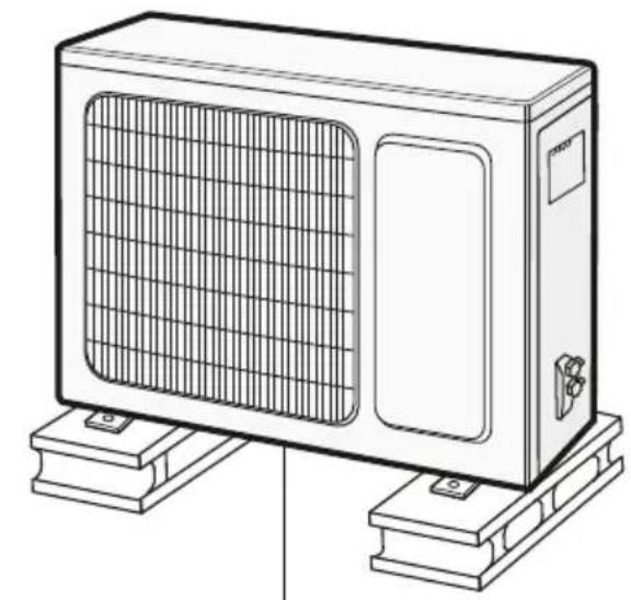
natural_image
Line drawing of a rectangular air conditioner unit mounted on a base, showing grille and vent slots (no text or symbols)at least 3 cm above the floor
Step two: install drain joint
unit)
- Connect the outdoor drain joint into the hole on the chassis, as shown in the picture below.
- Connect the drain hose into the drain vent.
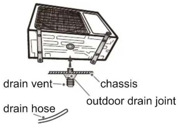
Step three: fix outdoor unit gnitaeh dna gnilooc rof ylnO(1 Place the outdoor unit on the
support.
2. Fix the foot holes of outdoor unit with bolts.
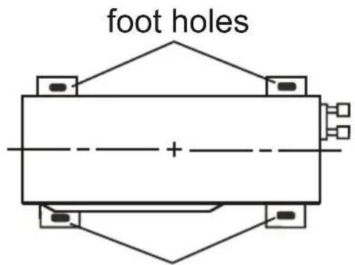
foot holes
Installation of outdoor unit
Step four: connect indoor and outdoor pipes
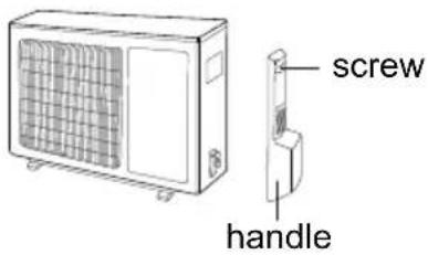
- Remove the screw on the right handle of outdoor unit and then remove the handle.
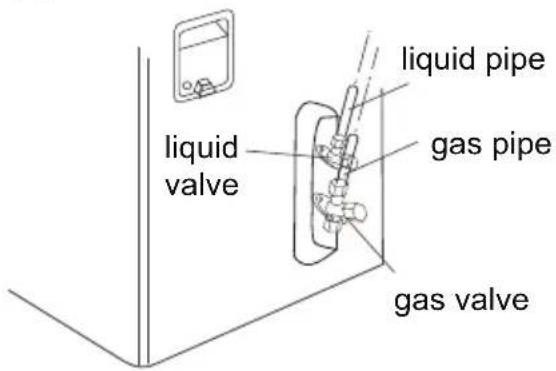
- Remove the screw cap of valve and aim the pipe joint at the bellmouth of pipe.
- Pretightening the union nut with hand.
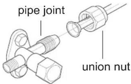
- Tighten the union nut with torque wrench by referring to the sheet below.
| Hex nut diameter | Tightening torque (N·m) |
| Φ 6 | 15~20 |
| Φ 9.52 | 30~40 |
| Φ 12 | 45~55 |
| Φ 16 | 60~65 |
| Φ 19 | 70~75 |
Step five: connect outdoor electric wire
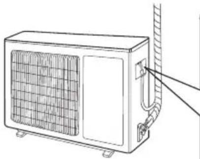
- Remove the wire clip; connect the power connection wire and signal control wire (only for cooling and heating unit) to the wiring terminal according to the color; fix them with screws.
natural_image
Line drawing of a wall-mounted air conditioner unit with ventilation grille and hose (no text or symbols)09、12K Heat pump type:
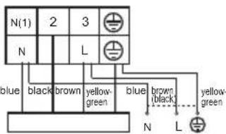
Indoor unit connection POWER
18、24K Heat pump type:
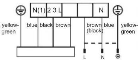
Indoor unit connection POWER
Note: The wiring board is for reference only. Please refer to the actual one.
Installation of outdoor unit
- Fix the power connection wire and signal control wire with wire clip (only for cooling and heating unit).
Note:
- After tighten the screw, pull the power cord slightly to check if it is firm.
- Never cut the power connection wire to prolong or shorten the distance.
Step six: neaten the pipes
- The pipes should be placed along the wall, bent reasonably and hidden possibly. Min. semidiameter of bending the pipe is 10 cm.
- If the outdoor unit is higher than the wall hole, you must set a U-shaped curve in the pipe before pipe goes into the room, in order to prevent rain from getting into the room.
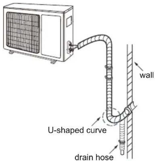
Note:
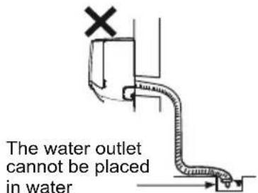
- The through-wall height of drain hose should not be higher than the outlet pipe hole of indoor unit.

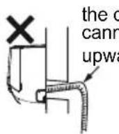
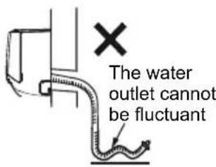
- The water outlet cannot be placed in water in order to drain smoothly.
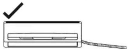
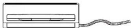
- Slant the drain hose slightly downwards. The drain hose cannot be curved, raised and fluctuant, etc.
natural_image
Simple line drawing of a device with a checkmark and a coiled cable (no text or symbols)✗ The drain hose cannot be fluctuant
natural_image
Simple line drawing of a rectangular device with a coiled cable extending from its side (no text or symbols)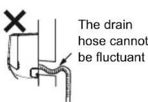
Vacuum pumping
Use vacuum pump
- Remove the valve caps on the liquid valve and gas valve and the nut of refrigerant charging vent.
- Connect the charging hose of piezometer to the refrigerant charging vent of gas valve and then connect the other charging hose to the vacuum pump.
- Open the piezometer completely and operate for 10 - 15min to check if the pressure of piezometer remains in -0.1MPa.
- Close the vacuum pump and maintain this status for 1 - 2 minutes to check if the pressure of piezometer remains in -0.1MPa . If the pressure decrea
- Remove the piezometer, open the valve core of liquid valve and gas valve completely with inner hexagon spanner.
- Tighten the screw caps of valves and refrigerant charging vent.
- Reinstall the handle.
Leakage detection
- With leakage detector:
Check if there is leakage with leakage detector.
- With soap water:
If leakage detector is not available, please use soap water for leakage detection.
Apply soap water at the suspected position and keep the soap water for more than 3 minutes. If there are air bubbles coming out of this position, there is a leakage.
Check after installation
- Check according to the following requirement after finishing installation.
| Items to be checked Possible malfunction | |
| Has the unit been installed firmly? | The unit may drop, shake or emit noise. |
| Have you done the refrigerant leakage test? | It may cause insufficient cooling (heating) capacity. |
| Is heat insulation of pipeline sufficient? | It may cause condensation and water dripping. |
| Is water drained well? | It may cause condensation and water dripping. |
| Is the voltage of power supply according to the voltage marked on the nameplate? | It may cause malfunction or damaging the parts. |
| Is electric wiring and pipeline installed correctly? | It may cause malfunction or damaging the parts. |
| Is the unit grounded securely? It may cause electric leakage. | |
| Does the power cord follow the specification? | It may cause malfunction or damaging the parts. |
| Is there any obstruction in the air inlet and outlet? | It may cause insufficient cooling (heating) capacity. |
| The dust and sundries caused during installation are removed? | It may cause malfunction or damaging the parts. |
| The gas valve and liquid valve of connection pipe are open completely? | It may cause insufficient cooling (heating) capacity. |
| Is the inlet and outlet of piping hole been covered? | It may cause insufficient cooling (heating) capacity or waster electricity. |
Test operation
1. Preparation of test operation
- Specify the important notes for air conditioner to the client.
2. Method of test operation
- Put through the power, press ON/OFF button on the remote controller to start operation.
- Press MODE button to select AUTO, COOL, DRY, FAN and HEAT to check whether the operation is normal or not.
- If the ambient temperature is lower than 16, the air conditioner cannot start cooling.
Pipe expanding method
Note:
Improper pipe expanding is the main cause of refrigerant leakage. Please expand the pipe according to the following steps:
A: Cut the pipe
- Confirm the pipe length according to the distance of indoor unit and outdoor unit.
- Cut the required pipe with pipe cutter.
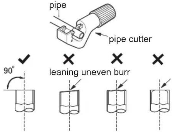
B: Remove the burrs
- Remove the burrs with shaper and prevent the burrs from getting into the pipe.
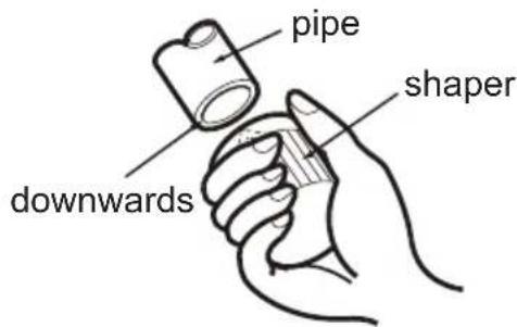
C: Put on suitable insulating pipe
D: Put on the union nut
- Remove the union nut on the indoor connection pipe and outdoor valve; install the union nut on the pipe.
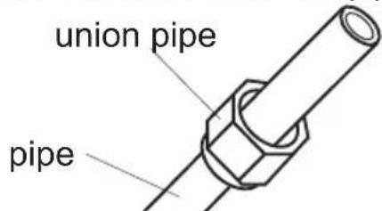
E: Expand the port
- Expand the port with expander.
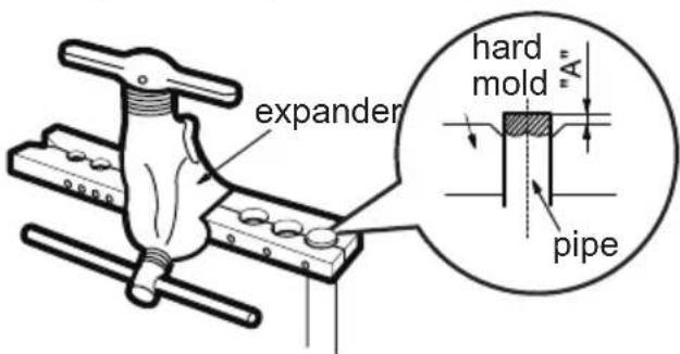
Note:
- "A" is different according to the diameter, please refer to the sheet below:
| Outer diameter (mm) | A (mm) | |
| Max Min | ||
| Φ6 - 6.35 (1/4") | 1.3 | 0.7 |
| Φ9.52 (3/8") | 1.6 | 1.0 |
| Φ12-12.7 (1/2") | 1.8 | 1.0 |
| Φ15.8-16 (5/8") | 2.4 | 2.2 |
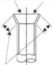
F: Inspection
- Check the quality of expanding port. If there is any blemish, expand the port again according to the steps above.
smooth surface
natural_image
Pure technical diagram of a cylindrical object with internal flow arrows, no text or symbols presentimproper expanding

leaning

damaged surface

crack

uneven thickness
Safety precautions for installing and relocating the unit
To ensure safety, please be mindful of the following preasuti
WARNING
- When installing or relocating the unit, be sure to keep the refrigerant circuit free from air or substances other than the specified refrigerant. Any presence of air or other foreign substance in the refrigerant circuit will cause system pressure rise or compressor rupture, resulting in injury.
- When installing or moving the unit, do not charge the refrigerant which is not comply with that on the nameplate or unqualified refrigerant. Otherwise, it may cause abnormal operation, wrong action, mechanical malfunction or even series safety accident.
- When refrigerant needs to be recovered during relocating or repairing the unit, be sure that the unit is running in cooling mode. Then, fully close the valve at high pressure side (liquid valve). About 30 - 40 seconds later, fully close the valve at low pressure side (gas valve), immediately stop the unit and disconnect power. Please not that the time for refrigerant recovery should not exceed 1 minute. If refrigerant recovery takes too much time, air may be sucked in and cause pressure rise or compressor rupture, resulting in injury.
- During refrigerant recovery, make sure that liquid valve and gas valve are fully closed and power is disconnected before detaching the connection pipe. If compressor starts running when stop valve is open and connection pipe is not yet connected, air will be sucked in and cause pressure rise or compressor rupture, resulting in injury.
- When installing the unit, make sure that connection pipe is securely connected before the compressor starts running. If compressor starts running when stop valve is open and connection pipe is not yet connected, air will be sucked in and cause pressure rise or compressor rupture, resulting injury.
- Prohibit installing the unit at the place where there may be leaked corrosive gas or flammable gas. If there are leaked gasses around the unit, it may cause explosion and other accidents.
- DO NOT use extension cords for electrical connections. If the electric wire is not long enough, please contact a local authorized service center and ask for a proper electric wire. Poor connections may lead to electric shock or fire.
- Use the specified types of wires for electrical connections between the indoor and outdoor units. Firmly clamp the wires so that their terminals receive not external stresses. Electric wires with insufficient capacity, wrong wire connections and insecure wire terminals may cause electric shock or fire.
flowchart
graph LR
    A["Auto"] --> B["Low speed"]
    B --> C["Low-Medium speed"]
    C --> D["Medium speed"]
    D --> E["Medium-High speed"]
    E --> F["High speed"]
Σημείωση:
natural_image
Illustration of two hands holding a rectangular device with curved arrows indicating motion or force (no text or symbols)natural_image
Hand holding a textured surface with a downward arrow, no visible text or symbolsnatural_image
Illustration of two hands holding a grid-patterned sheet with a tool, no text or symbols presentnatural_image
Line drawing of a car air conditioner unit with hand pressing down (no text or symbols)natural_image
Technical illustration of a mechanical assembly with no visible text or symbolsμονωμένος σωλήνας
natural_image
Diagram of a pipe joint with internal channels and an arrow indicating direction (no text or symbols)σωλήνας αποχέτευσης
μονωμένος σωλήνας
natural_image
Line drawing of a rectangular air conditioner unit mounted on a base, with no visible text or symbols.natural_image
Simple line drawing of a rectangular device with a diagonal line extending from it, no text or symbols present.natural_image
Diagram of a conical container with liquid inside, showing light rays reflecting from the side (no text or labels)íso μήκος
stops at current position)
flowchart
graph TD
    A["no display"] --> B["House"]
    B --> C["House"]
    C --> D["House"]
    D --> A
natural_image
Illustration of hands lifting a wall-mounted air conditioner (no text or symbols)Rimuovere i filtri
natural_image
Hand holding a white object with a curved arrow indicating direction (no text or symbols visible)Pulire i filtri
natural_image
Line drawing of a hand pressing down on a wall-mounted air conditioner unit (no text or symbols)Nota:
natural_image
Line drawing of a rectangular air conditioner unit with grid grille and base-mounted base (no text or symbols)natural_image
Simple line drawing of a rectangular device with a checkmark and a coiled cable, no text or symbols present.
natural_image
Simple line drawing of a rectangular object with a wavy line extending from its side (no text or symbols)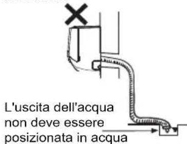
natural_image
Pure diagram of a cylindrical object with internal lines and arrows indicating direction, no text or symbols present.Certifi cate of compliance CE
TOYOTOMI CO., LTD declares that this product complies with the general requirements pursuant to the following European Directives:
LVD: 2014/35/EU
EMC: 2014/30/EU
RoHS: (EU)2015/863
ERP: 2011/65/EU
RED: 2014/53/EU
WiFi: Wireless maximum transmit power: 18dBm
Wireless frequency range: 2412MHz - 2472MHz
Therefore the product has been marked with the CE symbol and the
Declaration of Conformity has been issued and is available to the competent authorities regulating the market.
It is prohibited to reprint or reproduction of all or part of this manual in any manner without written permission of TOYOTOMI CO., LTD
This product is made in China

- The Refrigerant
- WARNING :
- Precautions
- WARNING
- Operation and Maintenance
- Attachment
- Working temperature range
- NOTICE:
- Parts Name
- Buttons on remote controller
- Introduction for icons on display screen
- Introduction for buttons on remote controller
- Note:
- ON/OFF button
- MODE button
- FAN button
- TURBO butto n
- ▲/▼ button
- button (not available)
- button
- SLEEP button
- Sleep Mode 1
- Sleep Mode 2
- During Cooling mode:
- During Heating mode:
- Sleep Mode 3
- I SENSE button
- TIMER ON / TIMER OFF button
- CLOCK button
- QUIET button
- Wi-Fi button
- LIGHT button
- / button
- TEMP button
- Function introduction for combination buttons
- Energy-saving function
- 8° cheating function
- Child lock function
- Temperature display switchover function
- Operation guide
- Replacement of batteries in remote controller
- NOTICE
- Emergency operation
- WARNING:
- Clean and maintenance
- Clean surface of indoor unit
- Clean filter
- Open panel
- Remove filter
- Clean filter
- Install filter
- Checking before use-season
- Checking after use-season
- Notice for recovery
- Malfunction analysis
- General phenomenon analysis
- Error Code
- Tools for installation
- Selection of installation location
- Requirements for electric connection
- Safety precaution
- Grounding requirement
- Installation of indoor unit
- Step two: install wall-mounting frame
- Step three: open piping hole
- Step four: outlet pipe
- Step five: connect the pipe of indoor unit
- Step six: install drain hose
- Step seven: connect wire of indoor unit
- Step eight: bind up pipe
- Step nine: hang the indoor unit
- Configuration of connection pipe
- Safety operation of flammable refrigerant
- Qualification requirement for installation and maintenance man
- Installation notes
- Maintenance notes
- Welding
- Filling the refrigerant
- Safety instructions for transportation and storage
- Installation of outdoor unit
- Step one: fix the support of outdoor unit
- Step two: install drain joint
- unit)
- Step three: fix outdoor unit gnitaeh dna gnilooc rof ylnO(1 Place the outdoor unit on the
- Step four: connect indoor and outdoor pipes
- Step five: connect outdoor electric wire
- Step six: neaten the pipes
- Vacuum pumping
- Use vacuum pump
- Leakage detection
- Check after installation
- Test operation
- Preparation of test operation
- Method of test operation
- Pipe expanding method
- Safety precautions for installing and relocating the unit
- Σημείωση:
- Rimuovere i filtri
- Pulire i filtri
- Nota:
- Certifi cate of compliance CE
Brand : Toyotomi
Model : TKN/TKG-671R32
Category : Air-conditioner