
TopTower N8850 - NAS Thecus - Free user manual and instructions
Find the device manual for free TopTower N8850 Thecus in PDF.


User questions about TopTower N8850 Thecus
0 question about this device. Answer the ones you know or ask your own.
Ask a new question about this device
Download the instructions for your NAS in PDF format for free! Find your manual TopTower N8850 - Thecus and take your electronic device back in hand. On this page are published all the documents necessary for the use of your device. TopTower N8850 by Thecus.
USER MANUAL TopTower N8850 Thecus
N8900 series/N12000 series/N16000 series/
N5550/N5810/N5810PRO/N6850/N8850/N10850/
N7700PRO V2/N7710 series/N8800PRO V2 /
N8810U series/N4510U series/N7510/N7770-10G/N8880U-10G
Copyright and Trademark Notice
Thecus and other names of Thecus products are registered trademarks of Thecus Technology Corp. Microsoft, Windows, and the Windows logo are registered trademarks of Microsoft Corporation. Apple, iTunes and Apple OS X are registered trademarks of Apple Computers, Inc. All other trademarks and brand names are the property of their respective owners. Specifications are subject to change without notice.
Copyright © 2015 Thecus Technology Corporation. All rights reserved.
About This Manual
All information in this manual has been carefully verified to ensure its correctness. In case of an error, please provide us with your feedback. Thecus Technology Corporation reserves the right to modify the contents of this manual without notice.
Product name: Thecus N8900 / N12000 / N16000
series/N6850/N8850/N10850/N7700PRO V2/N8800PRO V2/N7710 series/N8810U series/N5550/N4510U series/N7510/N5810/N5810PRO/N7770-10G/N8880U-10G Manual Version: 6.2
Release Date: October 2015
Limited Warranty
Thecus Technology Corporation guarantees all components of Thecus NAS products are thoroughly tested before they leave the factory and should function normally under general usage. In case of any system malfunctions, Thecus Technology Corporation and its local representatives and dealers are responsible for repair without cost to the customer if the product fails within the warranty period and under normal usage. Thecus Technology Corporation is not responsible for any damage or loss of data deemed to be caused by its products. It is highly recommended that users conduct necessary back-up practices.
Check the functions that are available on your particular Thecus NAS model at:
http://www.Thecus.com
Safety Warnings
For your safety, please read and follow the following safety warnings:
Read this manual thoroughly before attempting to set up your Thecus IP storage.
Your Thecus IP storage is a complicated electronic device. DO NOT attempt to repair it under any circumstances. In the case of malfunction, turn off the power immediately and have it repaired at a qualified service center. Contact your vendor for details.
DO NOT allow anything to rest on the power cord and DO NOT place the power cord in an area where it can be stepped on. Carefully place connecting cables to avoid stepping or tripping on them.
Your Thecus IP storage can operate normally under temperatures between 5°C and 40°C, with relative humidity of 20% – 85%. Using Thecus IP storage under extreme environmental conditions could damage the unit.
Ensure that the Thecus IP storage is provided with the correct supply voltage. Plugging the Thecus IP storage to an incorrect power source could damage the unit.
Do NOT expose Thecus IP storage to dampness, dust, or corrosive liquids.
Do NOT place Thecus IP storage on any uneven surfaces.
DO NOT place Thecus IP storage in direct sunlight or expose it to other heat sources.
DO NOT use chemicals or aerosols to clean Thecus IP storage. Unplug the power cord and all connected cables before cleaning.
DO NOT place any objects on the Thecus IP storage or obstruct its ventilation slots to avoid overheating the unit.
Keep packaging out of the reach of children.
If disposing of the device, please follow your local regulations for the safe disposal of electronic products to protect the environment.
Risk of explosion if battery is replaced by an incorrect type.
Disposition of used batteries according to the instructions
Table of Contents
Copyright and Trademark Notice 2
About This Manual....2
Limited Warranty....2
Safety Warnings....3
Table of Contents 4
Chapter 1: Introduction......7
Overview....7
Product Highlights....7
Package Contents....9
Front Panel....10
Rear Panel....23
Chapter 2: Hardware Installation .... 39
Overview 39
Before You Begin....39
Cable Connections 39
Chapter 3: First Time Setup....43
Overview 43
Thecus Setup Wizard 43
LCD Operation (N7700PRO V2/N8800PRO V2/ N7710 series/N8810U series/N5550/N5810/N5810PRO/N4510U
series/N7510/N7770-10G/N8880U-10G) 45
OLED Operation(Does not apply to the N7700PRO V2/N8800PRO V2/N7710 series/N8810U series/N5550/N5810/N5810PRO/N4510U series/N7510/N7770-10G/N8880U-10G) 47
USB Copy 47
Typical Setup Procedure....48
Chapter 4: System Administration....50
Overview 50
Web Administration Interface 50
My Favorite....51
Logout 53
Language Selection....53
System Information 54
General 54
Status 55
Logs....55
Syslog Management.... 57
System Monitor 58
Hardware Information 60
User Access Log 60
System Management 63
Date and Time: Setting system time 63
Notification configuration.... 63
Firmware Upgrade 64
Schedule Power On/Off....65
Administrator Password 66
Config Mgmt 67
Factory Default....67
Power Management: 68
File System Check 69
Wake-Up On LAN (WOL) 71
SNMP Support 71
UI Login Function 71
System Network 72
Networking 72
VLAN....73
DHCP/RADVD 74
Linking Aggregation 75
Additional LAN....77
Storage Management 79
Disk Information....79
RAID Information 82
NAS Stacking 95
ISO Mount....101
Share Folder 104
Folder and sub-folders Access Control List (ACL) 107
Snapshot....109
iSCSI 113
iSCSI Thin-Provisioning 119
Advance Option 120
Disk Clone and Wipe 121
High-Availability (N8900, N12000 series/N16000 series only) .....123
User and Group Authentication 132
ADS/NT Support 132
Local User Configuration....134
Local Group Configuration....136
Batch Users and Groups Creation....138
User Quota 139
User and Group Backup....139
LDAP Support....140
Network Service....140
Samba / CIFS 140
AFP (Apple Network Setup)....143
NFS Setup 144
FTP 144
TFTP 146
WebService....146
UPnP 147
Bonjour Setting 147
SSH 148
DDNS....149
UPnP Port Management ....149
WebDAV....151
Auto-Thumbnail....152
Thecus ID....152
VPN Client 154
VPN Server 155
Application Server 157
iTunes® Server....157
App Installation....157
Auto App Installation....158
Backup 159
Dual DOM (N12000 series/N16000 series/N8900 series only)......159
Rsync Target Server 159
ACL Backup and Restore....161
Data Burn....162
Data Guard (Remote Backup)....165
Full Backup 167
Custom Backup.... 169
iSCSI Backup.... 171
Restore....172
Data Guard (Local Backup) 176
USB Copy 192
Volume Expansion Management ....194
Thecus Backup Utility....195
Windows XP Data Backup ....195
Apple OS X Backup Utilities....196
External Devices....196
Printers 196
Uninterrupted Power Source....201
Chapter 5: Tips and Tricks....202
USB and eSATA Storage Expansion....202
Remote Administration....202
Part I - Setup a DynDNS Account ......203
Part II - Enable DDNS on the Router 203
Part III - Setting up Virtual Servers (HTTPS)....203
Firewall Software Configuration 203
Replacing Damaged Hard Drives 204
Hard Drive Damage 204
Replacing a Hard Drive....204
RAID Auto-Rebuild....204
Chapter 6: Troubleshooting....205
Forgot My Network IP Address....205
Can't Map a Network Drive in Windows XP 205
Restoring Factory Defaults 205
Problems with Time and Date Settings....206
Dual DOM Supports for Dual Protection (N12000 series/N16000
series/N8900 series only) 206
Appendix A: Customer Support.... 207
Appendix B: RAID Basics....208
Overview 208
Benefits....208
Improved Performance....208
Data Security 208
RAID Levels....208
Appendix C: How to open the top cover 211
N8900 series: 211
N12000 series: 212
N16000 series: 212
Appendix D: Active Directory Basics....213
Overview 213
What is Active Directory? 213
ADS Benefits....213
Appendix E: Licensing Information.... 214
Overview 214
Source Code Availability 214
CGIC License Terms....215
GNU General Public License....215
Chapter 1: Introduction
Overview
Thank you for choosing the Thecus IP Storage Server. The Thecus IP storage is an easy-to-use storage server that allows a dedicated approach to storing and distributing data on a network. Data reliability is ensured with RAID features that provide data security and recovery—over multiple Terabyte of storage are available using RAID 5 and RAID 6. Gigabit Ethernet ports enhance network efficiency, allowing Thecus IP storage to take over file management functions, increase application and data sharing and provide faster data response. The Thecus IP storage offers data mobility with a disk roaming feature that lets you swap working hard drives for use in other Thecus IP storage, securing the continuity of data in the event of hardware failure. The Thecus IP storage allows data consolidation and sharing between Windows (SMB/CIFS), UNIX/Linux, and Apple OS X environments. The Thecus IP storage's user-friendly GUI supports multiple Languages.
Product Highlights
File Server
First and foremost, the Thecus IP storage allows you to store and share files over an IP network. With a Network Attached Storage (NAS) device, you can centralize your files and share them easily over your network. With the easy-to-use web-based interface, users on your network can access these files in a snap.
To learn about the Web User Interface, go to
Chapter 4: Using the Thecus IP Storage > Web Administration Interface
FTP Server
With the built-in FTP Server, friends, clients, and customers can upload and download files to your Thecus IP storage over the Internet with their favorite FTP programs. You can create user accounts so that only authorized users have access.
To set up the FTP Server, refer to
Chapter 4: Network Service> FTP .
iTunes Server
With the built-in iTunes server capability, the Thecus IP storage enables digital music to be shared and played anywhere on the network!
To set up the iTunes Server, refer to
Chapter 4: Application Server>iTunes Configuration.
Printer Server
With the Thecus IP storage's Printer Server, you can easily share an IPP printer with other PCs connected to your network.
To set up the Printer Server, refer to
Chapter 4: External Devices Server>Printer Information.
Multiple RAID
Thecus IP storage supports multiple RAID volumes on one system. So, you can create RAID 0 for your non-critical data, and create RAID 1,5,6,50 or 60 (depend on model) for mission-critical data. Create the RAID levels depending on your needs.
To configure RAID modes on the Thecus IP storage, refer to
Chapter 4: Storage Management >RAID Information.
iSCSI Capability
Thecus IP storage is not only a file server, but it also supports iSCSI initiators. Your server can access Thecus IP storage as a direct-attached-storage over the LAN or Internet. There is no easier way to expand the capacity of your current application servers. All the storage needs can be centrally managed and deployed. This brings ultimate flexibility to users.
To set up an iSCSI volume, refer to
Chapter 4: Storage Management > iSCSI
Superior Power Management
Thecus IP storage supports schedule power on/off. With this feature, administrator can set at what time to turn on or off the system. This feature is a big plus for people who want to conserve energy. Wake-On-LAN enables administrator to remotely turn on the system without even leaving their own seat.
To schedule system on and off, refer to
Chapter 4: System Management> Scheduled Power On/Off
Package Contents
N8900/N12000/N16000 Series/N8800PRO V2/N8810U series/
N4510U-R/N4510U PRO-R/N8880U-10G
The Thecus IP storage should contain the following common items:
- System Unit x1
● QIG (Quick Installation Guide) x1
● CD-Title (Acronis backup CD & Universal CD) - Ethernet Cable x1
- Accessory bag x1
- HDD Compatibility list Card x1
● Multiple Languages Warranty Card x1 - Power cord x2
N6850/N8850/N10850/N7700PRO V2/N7710 series/N5550/N4510U-S/
N7510/N4510U PRO-S/N5810/N5810PRO/N7770-10G
The Thecus IP storage should contain the following common items:
- System Unit x1
• QIG (Quick Installation Guide) x1
● CD-Title (Acronis backup CD & Universal CD) - Ethernet Cable x1
- Accessory bag x1
- HDD Compatibility list Card x1
● Multiple Languages Warranty Card x1 - Power cord x1
Please check to see if your package is complete. If you find that some items are missing, contact your dealer.
Front Panel
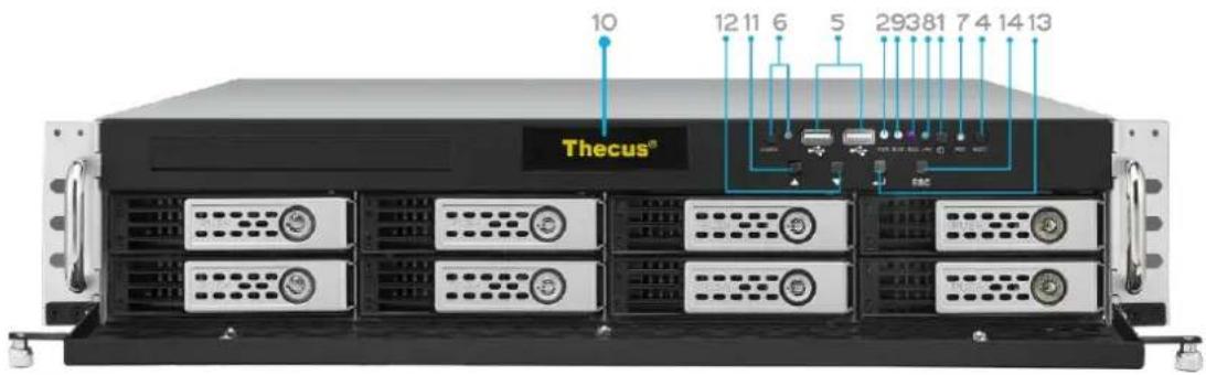
N8900 series:
text_image
10 12 11 6 5 29381 7 4 14 13 Thecus®| Front Panel | |
| Item | Description |
| 1.Power Button | Power on/off N8900 |
| 2.Power LED | Solid green:System is power on. |
| 3.System error LED | Solid RED: System error. |
| 4.Mute button | Mute the system fan alarm. |
| 5.USB Port | USB 2.0 port for compatible USB devices, such as USB disks and USB printers |
| 6. Locator button / LED | Press the button, the back led will light up to identify the system position of the rack |
| 7. RST | Reboot system. |
| 8. LAN | Blinking green: network activitySolid green: network link |
| 9. BUSY | Blinking orange: system startup or system maintenance; data currently inaccessible |
| 10.OLED | Displays current system status and messagesOLED screen saver will be enabled after screen is idle for more than 3 minutesOLED screen will be turn off after idle for more than 6 minutes |
| 11.Up Button ▲ | Push to scroll up when using the OLED display |
| 12.Down Button ▼ | Push to enter USB copy operation screen |
| 13.Enter Button ↓ | Push to enter OLED operate password for basic system setting |
| 14.Escape Button ESC | Push to leave the current OLED menu |
N12000 series:
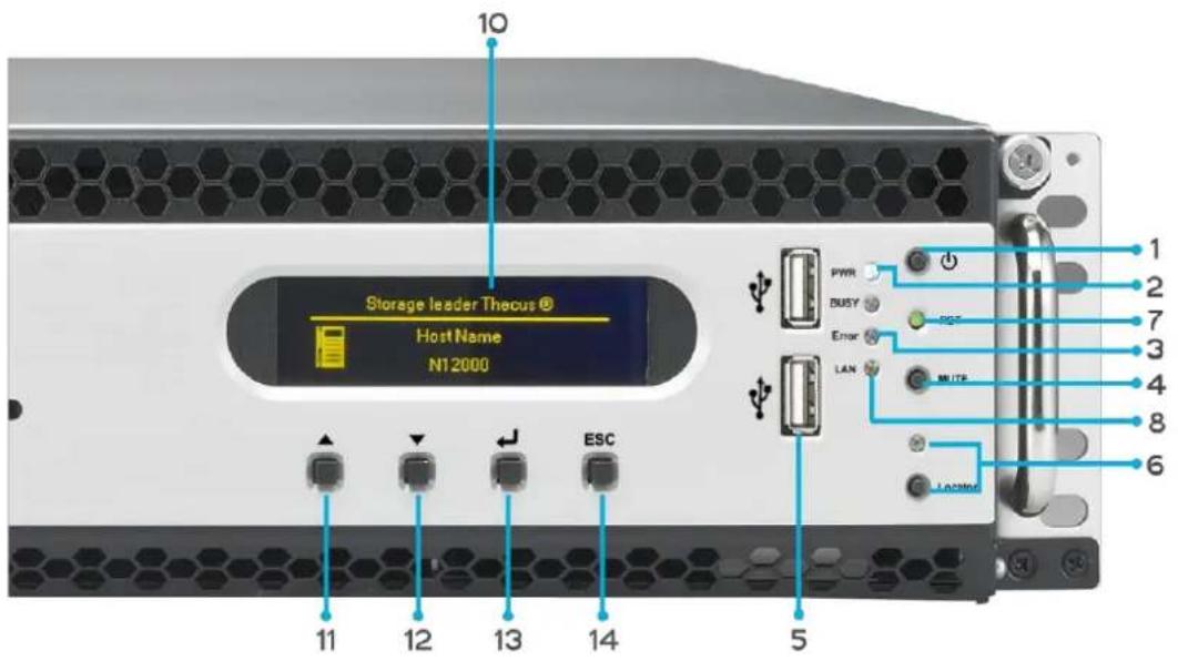
The Thecus N12000 series front panel has the device's controls, indicators, and hard disk trays:
text_image
Storage leader Thecus® Host Name N12000 10 11 12 13 14 5 PWR BUSY ESC Error LAN MUTE LOCKed 1 2 7 3 4 8 6| Front Panel | |
| Item | Description |
| 1.Power Button | Power on/off N12000 |
| 2.Power LED | Solid green:System is power on. |
| 3.System error LED | Solid RED: System error. |
| 4.Mute button | Mute the system fan alarm. |
| 5.USB Port | USB 2.0 port for compatible USB devices, such as USB disks and USB printers |
| 6. Locator button / LED | Press the button, the back led will light up to identify the system position of the rack |
| 7. RST | Reboot system. |
| 8. LAN | Blinking green: network activitySolid green: network link |
| 9. BUSY | Blinking orange: system startup or system maintenance; data currently inaccessible |
| 10.OLED | Displays current system status and messagesOLED screen saver will be enabled after screen is idle for more than 3 minutesOLED screen will be turn off after idle for more than 6 minutes |
| 11.Up Button ▲ | Push to scroll up when using the OLED display |
| 12.Down Button ▼ | Push to enter USB copy operation screen |
| 13.Enter Button ↓ | Push to enter OLED operate password for basic system setting |
| 14.Escape Button ESC | Push to leave the current OLED menu |
N16000 series:
The Thecus N16000 series front panel has the device's controls, indicators, and hard disk trays:
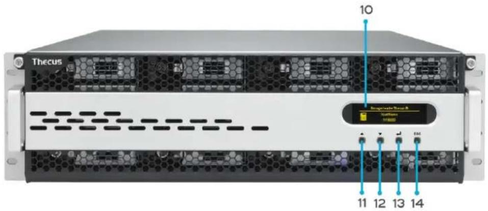
text_image
10 Thecus Biospectable Server 8 11 12 13 14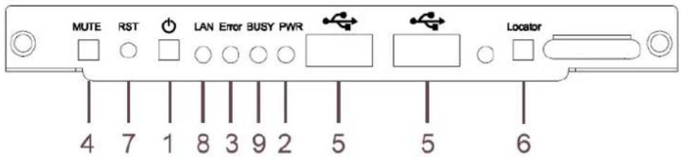
text_image
MUTE RST LAN Error BUSY PWR Locator 4 7 1 8 3 9 2 5 5 6| Front Panel | |
| Item | Description |
| 1.Power Button | Power on/off N16000 |
| 2.Power LED | Solid green:System is power on. |
| 3.System error LED | Solid RED: System error. |
| 4.Mute button | Mute the system fan alarm. |
| 5.USB Port | USB 2.0 port for compatible USB devices, such as USB disks and USB printers |
| 6. Locator button / LED | Press the button, the back led will light up to identify the rack position of the system |
| 7. RST | Reboot system. |
| 8. LAN | Blinking green: network activitySolid green: network link |
| 9. BUSY | Blinking orange: system startup or system maintenance; data currently inaccessible |
| 10.OLED | Displays current system status and messagesOLED screen saver will be enabled after screen is idle for more than 3 minutesOLED screen will be turn off after idle for more than 6 minutes |
| 11.Up Button ▲ | Push to scroll up when using the OLED display |
| 12.Down Button ▼ | Push to enter USB copy operation screen |
| 13.Enter Button ↓ | Push to enter OLED operate password for basic system setting |
| 14.Escape Button ESC | Push to leave the current OLED menu |
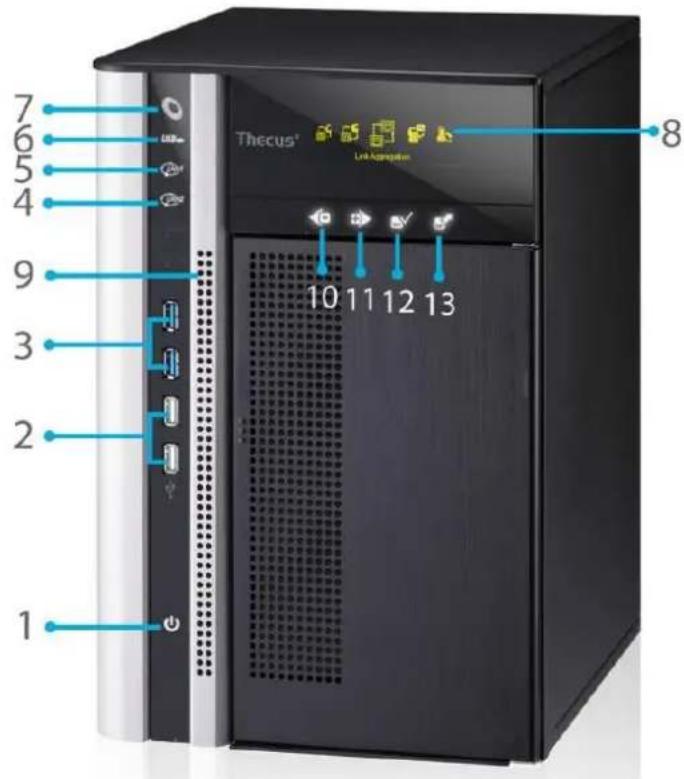
N6850:
The Thecus N6850's front panel has the device's controls, indicators, and hard disk trays:
text_image
7 6 5 4 9 3 2 1 8 Thecus® Link Appellation 10 11 12 13| Front Panel | |
| Item | Description |
| 1. Power Button | • Power on/off N6850 |
| 2. USB Port | • USB 2.0 port for compatible USB devices, such as digital cameras, USB disks, and USB printers. |
| 3. USB Port | • USB 3.0 port for compatible USB devices, such as digital cameras, USB disks, and USB printers. |
| 4. LAN2 LED | • Solid white: LAN2 Cable link• Blinking : Network activity |
| 5. LAN1 LED | • Solid white: LAN1 Cable link• Blinking : Network activity |
| 6. USB LED | • Solid white: USB busy• Solid Red: USB error |
| 7. System LED | • Solid white: System is power on. |
| 8. OLED | • Displays system status and information |
| 9. System Error LED | • Blinking RED: System error. |
| 10. Down Button | • Push to enter USB copy operation screen |
| 11. Up Button | • Push to scroll up when using the OLED display |
| 12. Enter Button | • Push to enter OLED operate password for basic system setting |
| 13. Escape Button | • Push to leave the current OLED menu |
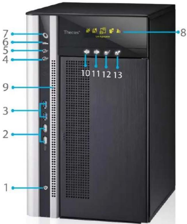
N8850:
The Thecus N8850's front panel has the device's controls, indicators, and hard disk trays:
text_image
7 6 5 4 9 3 2 1 Thecus® Line Agreen 10 11 12 13 8| Front Panel | |
| Item | Description |
| 1. Power Button | • Power on/off N8850 |
| 2. USB Port | • USB 2.0 port for compatible USB devices, such as digital cameras, USB disks, and USB printers. |
| 3. USB Port | • USB 3.0 port for compatible USB devices, such as digital cameras, USB disks, and USB printers. |
| 4. LAN2 LED | • Solid white: LAN2 Cable link• Blinking : Network activity |
| 5. LAN1 LED | • Solid white: LAN1 Cable link• Blinking : Network activity |
| 6. USB LED | • Solid white: USB busy• Solid Red: USB error |
| 7. System LED | • Solid white: System is power on. |
| 8. OLED | • Displays system status and information |
| 9. System Error LED | • Blinking RED: System error. |
| 10. Down Button | • Push to enter USB copy operation screen |
| 11. Up Button | • Push to scroll up when using the OLED display |
| 12. Enter Button | • Push to enter OLED operate password for basic system setting |
| 13. Escape Button | • Push to leave the current OLED menu |
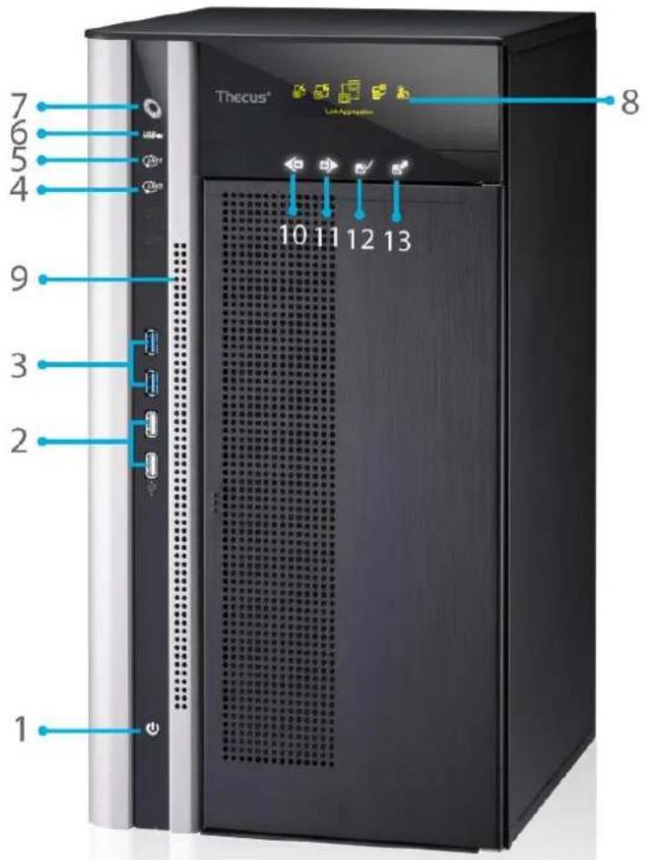
N10850:
The Thecus N10850's front panel has the device's controls, indicators, and hard disk trays:
text_image
7 6 5 4 9 3 2 1 8 Thecus® Lett Appliance 10 11 12 13| Front Panel | |
| Item | Description |
| 1. Power Button | • Power on/off N10850 |
| 2. USB Port | • USB 2.0 port for compatible USB devices, such as digital cameras, USB disks, and USB printers. |
| 3. USB Port | • USB 3.0 port for compatible USB devices, such as digital cameras, USB disks, and USB printers. |
| 4. LAN2 LED | • Solid white: LAN2 Cable link• Blinking : Network activity |
| 5. LAN1 LED | • Solid white: LAN1 Cable link• Blinking : Network activity |
| 6. USB LED | • Solid white: USB busy• Solid Red: USB error |
| 7. System LED | • Solid white: System is power on. |
| 8. OLED | • Displays system status and information |
| 9. System Error LED | • Blinking RED: System error. |
| 10. Down Button | • Push to enter USB copy operation screen |
| 11. Up Button | • Push to scroll up when using the OLED display |
| 12. Enter Button | • Push to enter OLED operate password for basic system setting |
| 13. Escape Button | • Push to leave the current OLED menu |
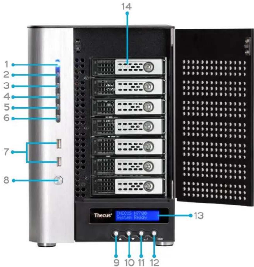
N7700PRO V2/N7710 series/N7770-10G:
The Thecus N7700PRO V2/N7710 series front panel has the device's controls, indicators, and hard disk trays:
text_image
1 2 3 4 5 6 7 8 14 13 9 10 11 12 Thecus® THECUS N7708 System Ready| Front Panel | |
| Item | Description |
| 1.Power LED | Solid blue: System is power on. |
| 2.System LED | Solid orange: system is being upgraded or system startup; data currently inaccessible |
| 3.WAN/LAN1 LED | Solid green: network linkBlinking green: network activity |
| 4.LAN2 LED | Solid green: network linkBlinking green: network activity |
| 5.USB Copy LED | Solid blue: files are being copied from a USB storage device |
| 6.eSATA link LED (N7700PROv2) | Solid blue: external eSATA device has connected |
| 7.USB Port | USB 2.0 port for compatible USB devices, such as USB disks. |
| 8.Power Button | Power on/off N7700PRO V2/N7710 series/N7770-10G |
| 9.Up Button ▲ | Push to scroll up when using the LCD display |
| 10.Down Button ▼ | Push to enter USB copy operation screen |
| 11.Enter Button ↓ | Push to enter LCD operate password for basic system setting |
| 12.Escape Button ESC | Push to leave the current LCD menu |
| 13.LCD Display | Displays current system status and warning messages |
| 14.HDD Trays | Seven 3.5” SATA HDD traysLocks are provided for added security |
N8800PRO V2/N8810U series/N8880U-10G:
The Thecus N8800PRO V2/N8810U series front panel has the device's controls, indicators, and hard disk trays:
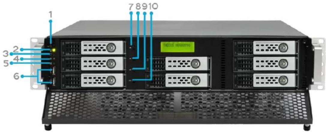
text_image
1 2 3 4 5 6 7 8 9 10 TEODUS H800PRO| Front Panel | |
| Item | Description |
| 1.Power Button | Power on/off N8800PRO V2/N8810U series/N8880U-10G |
| 2.Power LED | Solid green:System is power on. |
| 3.Reboot Button | Press to system reboot |
| 4.System fan alarm LED | Solid red:system fan failure notification |
| 5. Mute button | Mute the system fan alarm. |
| 6.USB Port | USB 2.0 port for compatible USB devices, such as USB disks, USB printers |
| 7.Up Button ▲ | Push to scroll up when using the LCD display |
| 8.Down Button ▼ | Push to enter USB copy operation screen |
| 9.Enter Button ↓ | Push to enter LCD operate password for basic system setting |
| 10.Escape Button ESC | Push to leave the current LCD menu |
N5550:
The Thecus N5550 front panel has the device's controls, indicators, and hard disk trays:
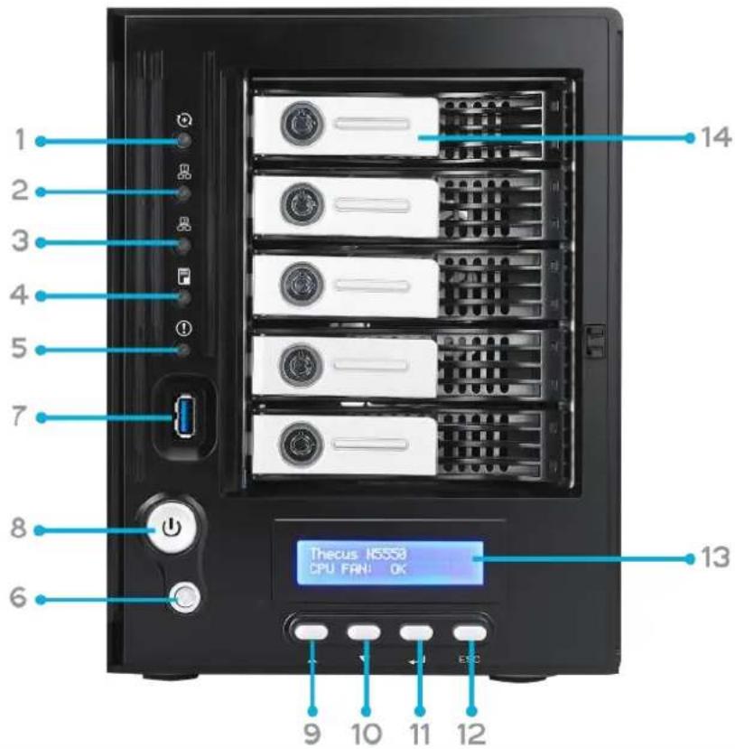
text_image
1 2 3 4 5 7 8 6 13 14 Thecus N5558 CPU FAN: OK 9 10 11 12 ESC| Front Panel | |
| Item | Description |
| 1.System LED | Blinking orange: System is being upgraded or ;is starting up; data currently inaccessible |
| 2.WAN/LAN1 LED | Solid green: Network linkBlinking green: Network activity |
| 3.LAN2 LED | Solid green: Network linkBlinking green: Network activity |
| 4.USB Copy LED | Solid blue: Files are being copied from a USB storage device |
| 5.Syetem Warning LED | Solid RED: System error |
| 6.Reset Button | Resets system configuration to default value. |
| 7.USB Port | USB 3.0 port for compatible USB devices, such as USB disks. |
| 8.Power Button/ Power LED | Power on/off N5550 and Power LED.Solid blue: System is power on. |
| 9.Up Button ▲ | Push to scroll up when using the LCD display. |
| 10.Down Button ▼ | Push to enter the USB copy operation screen. |
| 11.Enter Button ↓ | Push to enter LCD administrator password to access basic system setting. |
| 12.Escape Button ESC | Push to leave the current LCD menu. |
| 13.LCD Display | Displays current system status and warning messages. |
| 14.HDD Trays | Five 3.5” SATA HDD trays.Locks are provided for added security. |
N5810/N5810PRO:
The Thecus N5810/N5810PRO front panel has the device's controls, indicators, and hard disk trays:
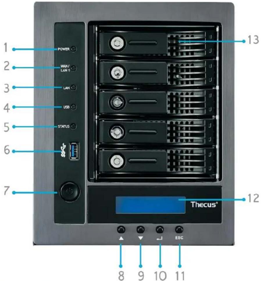
text_image
1 POWER 2 WIN/ LAN 1 3 LAN 4 USB 5 STATUS 6 7 12 Thecus® ESC 8 9 10 11 13| Front Panel | |
| Item | Description |
| 1. Power LED | • White: System is power on. |
| 2.WAN/LAN1 LED | • White: Network activity |
| 3.LAN2 LED | • White: Network activity |
| 4.USB Copy LED | • White: Files are being copied from a USB storage device• Red: USB copy error |
| 5. System LED | • White: System is being upgraded or ;is starting up; data currently inaccessible• RED: System error |
| 6.USB Port | • USB 3.0 port for compatible USB devices, such as USB disks. |
| 7.Power Button | • Power on/off N5810/N5810PRO and Power LED. |
| 8.Up Button ▲ | • Push to scroll up when using the LCD display. |
| 9.Down Button ▼ | • Push to enter the USB copy operation screen. |
| 10.Enter Button ↓ | • Push to enter LCD administrator password to access basic system setting. |
| 11.Escape Button ESC | • Push to leave the current LCD menu. |
| 12.LCD Display | • Displays current system status and warning messages. |
| 13.HDD Trays | • Five 3.5" SATA HDD trays.• Locks are provided for added security. |
N4510U:
The Thecus N4510U front panel has the device's controls, indicators, and hard disk trays:
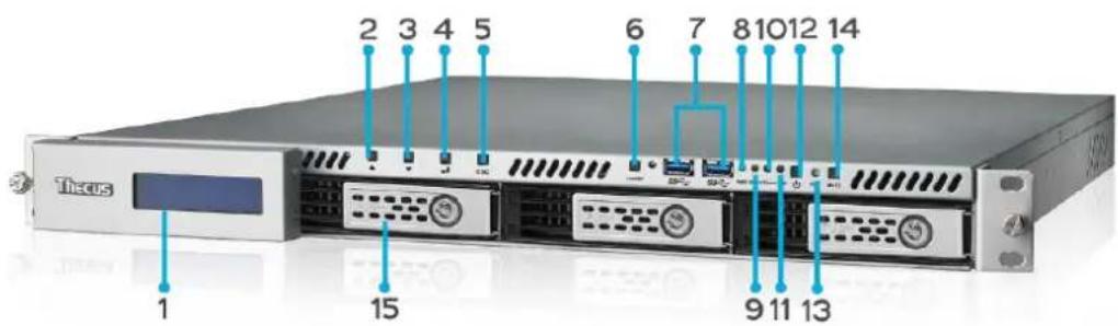
text_image
Tocus 1 2 3 4 5 6 7 8 10 12 14 15 9 11 13| Front Panel | |
| Item | Description |
| 1. LCD Display | Displays the current system status and warning messages.Displays hostname, WAN/LAN1/LAN2 IP addresses, RAID status, and current time. |
| 2. Up Button ▲ | Push to scroll up when using the LCD display. |
| 3. Down Button ▼ | Push to scroll down when using the LCD display. |
| 4.Enter Button ↓ | Push to confirm information entered into the LCD display. |
| 5. Escape Button ESC | Push to leave the current LCD menu. |
| 6. Locator Button | Turns on the LED backlight. |
| 7. USB Port | USB 3.0 port for compatible USB devices, such as digital cameras, USB disks, and USB printers. |
| 8. PWR LED | Solid Blue:System is powered on. |
| 9. Busy LED | Blinking orange:system startup or system maintenance; data currently inaccessible |
| 10. Error LED | Solid Red:System alert: Redundant power or system fan failure |
| 11. LAN LED | Solid green:network linkBlinking green:network activity |
| 12. Power Button | Power the N4510U on/off. |
| 13. Reset Button | Resets the N4510U. |
| 14. Mute Button | Mutes the system fan alarm (Can also be managed through the UI) |
| 15. HDD Trays | Four 3.5” SATA HDD trays.Locks are provided for added security. |
N4510U PRO:
The Thecus N4510U PRO front panel has the device's controls, indicators, and hard disk trays:
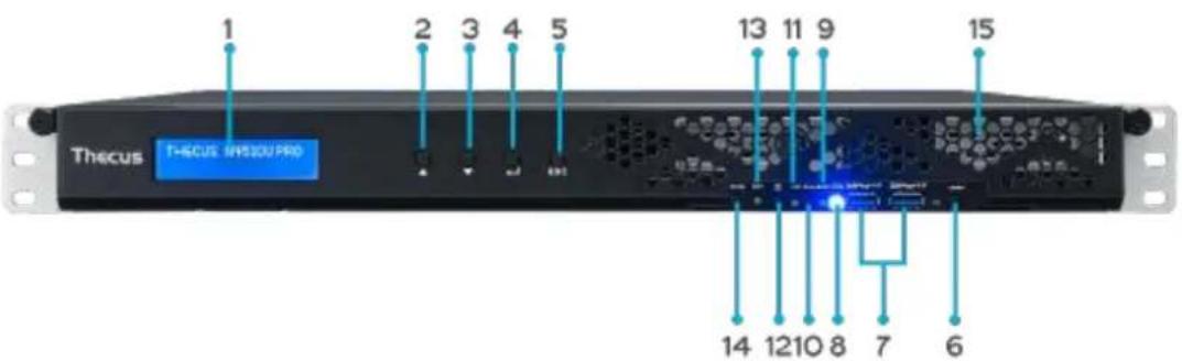
text_image
1 2 3 4 5 13 11 9 15 Thecus THCUS IN530U PRO 14 1210 8 7 6| Front Panel | |
| Item | Description |
| 1. LCD Display | Displays the current system status and warning messages.Displays hostname, WAN/LAN1 IP addresses, RAID status, and current time. |
| 2. Up Button ▲ | Push to scroll up when using the LCD display. |
| 3. Down Button ▼ | Push to scroll down when using the LCD display. |
| 4. Enter Button ↓ | Push to confirm information entered into the LCD display. |
| 5. Escape Button ESC | Push to leave the current LCD menu. |
| 6. Locator Button | Turns on the LED backlight. |
| 7. USB Port | USB 3.0 port for compatible USB devices, such as digital cameras, USB disks, and USB printers. |
| 8. PWR LED | Solid Blue: System is powered on. |
| 9. Busy LED | Blinking orange: system startup or system maintenance; data currently inaccessible |
| 10. Error LED | Solid Red: System alert: Redundant power or system fan failure |
| 11. LAN LED | Solid green: network linkBlinking green: network activity |
| 12. Power Button | Power the N4510U PRO on/off. |
| 13. Reset Button | Resets the N4510U PRO. |
| 14. Mute Button | Mutes the system fan alarm (Can also be managed through the UI) |
| 15. HDD Trays | Four 3.5” SATA HDD trays.Locks are provided for added security. |
N7510:
The Thecus N7510 front panel has the device's controls, indicators, and hard disk trays:
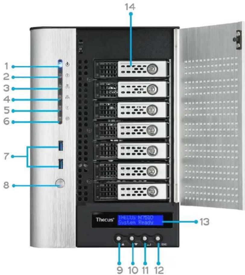
text_image
1 2 3 4 5 6 7 8 14 Thecus® N7510 System Ready 13 9 10 11 12| Front Panel | |
| Item | Description |
| 1.Power LED | Solid blue: System is power on. |
| 2.System LED | Solid orange: system is being upgraded or system startup; data currently inaccessible |
| 3.WAN/LAN1 LED | Solid green: network linkBlinking green: network activity |
| 4.LAN2 LED | Solid green: network linkBlinking green: network activity |
| 5.USB Copy LED | Solid blue: files are being copied from a USB storage device |
| 6.eSATA link LED | Solid blue: external eSATA device has connected |
| 7.USB Port | USB 3.0 port for compatible USB devices, such as USB disks. |
| 8.Power Button | Power on/off N7510 |
| 9.Up Button ▲ | Push to scroll up when using the LCD display |
| 10.Down Button ▼ | Push to enter USB copy operation screen |
| 11.Enter Button ↓ | Push to enter LCD operate password for basic system setting |
| 12.Escape Button ESC | Push to leave the current LCD menu |
| 13.LCD Display | Displays current system status and warning messages |
| 14.HDD Trays | Seven 3.5" SATA HDD traysLocks are provided for added security |
Rear Panel
N8900
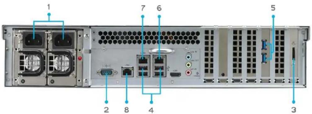
text_image
1 7 6 5 2 8 4 3| Back Panel | |
| Item | Description |
| 1.Power Connector | Connect the included power cords to these connectors |
| 2.Serial Port | This port is for external UPS device |
| 3.eSATA Port | eSATA port for high-speed storage expansion |
| 4.USB Port | USB 2.0 port for compatible USB devices, such as USB disks, and USB printers |
| 5.USB Port | USB 3.0 port for compatible USB devices. |
| 6.WAN/LAN1 Port | WAN/LAN1 port for connecting to an Ethernet network through a switch or router |
| 7.LAN2 Port | LAN2 port for connecting to an Ethernet network through a switch or router |
| 8.LAN3 Port | LAN3 port for connecting to an Ethernet network through a switch or router. |
N12000:
The N12000 rear panel features ports and connectors.
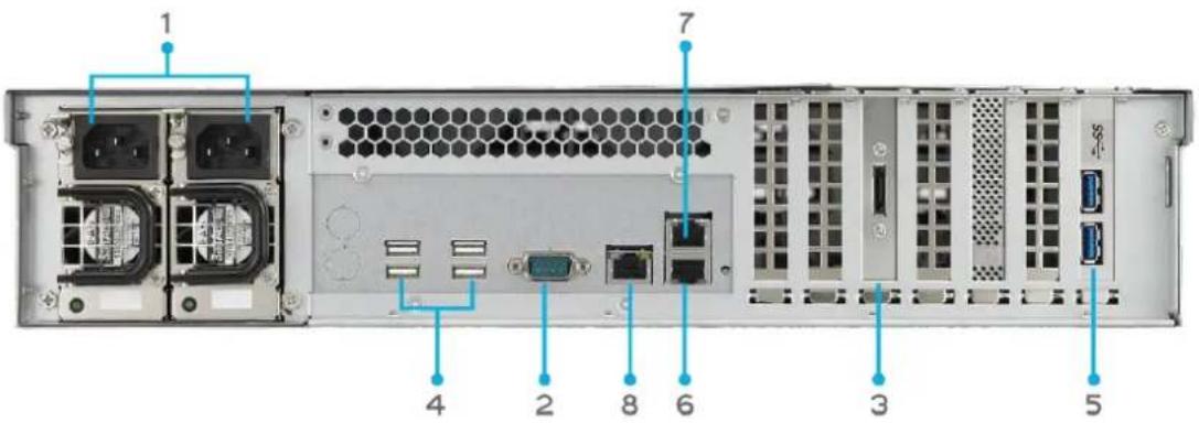
text_image
1 7 4 2 8 6 3 5| Back Panel | |
| Item | Description |
| 1.Power Connector | • Connect the included power cords to these connectors |
| 2.Serial Port | • This port is for external UPS device |
| 3.eSATA Port | • eSATA port for high-speed storage expansion |
| 4.USB Port | • USB 2.0 port for compatible USB devices, such as USB disks, and USB printers |
| 5.USB Port | • USB 3.0 port for compatible USB devices. |
| 6.WAN/LAN1 Port | • WAN/LAN1 port for connecting to an Ethernet network through a switch or router |
| 7.LAN2 Port | • LAN2 port for connecting to an Ethernet network through a switch or router |
| 8.LAN3 Port | • LAN3 port for HA connecting. |
N12000V/N12000PRO:
N12000V/N12000PRO rear panel features ports and connectors.
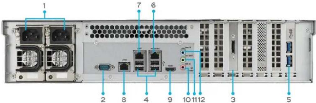
text_image
1 7 6 2 8 4 9 10 11 12 3 5| Back Panel | |
| Item | Description |
| 1.Power Connector | Connect the included power cords to these connectors |
| 2.Serial Port | This port is for external UPS device |
| 3.eSATA Port | eSATA port for high-speed storage expansion |
| 4.USB Port | USB 2.0 port for compatible USB devices, such as USB disks, and USB printers |
| 5.USB Port | USB 3.0 port for compatible USB devices. |
| 6.WAN/LAN1 Port | WAN/LAN1 port for connecting to an Ethernet network through a switch or router |
| 7.LAN2 Port | LAN2 port for connecting to an Ethernet network through a switch or router |
| 8.LAN3 Port | LAN3 port for HA connecting. |
| 9.HDMI Port | For Video/Audio out |
| 10. Mic input | Microphone input |
| 11. Line out | For Audio out |
| 12.Line in | For Audio in |
N16000:
The N16000 rear panel features ports and connectors.

text_image
1 4 2 8 6 7 3 5| Back Panel | |
| Item | Description |
| 1.Power Connector | Connect the included power cords to these connectors |
| 2.Serial Port | This port is for external UPS device |
| 3.eSATA Port | eSATA port for high-speed storage expansion |
| 4.USB Port | USB 2.0 port for compatible USB devices, such as USB disks, and USB printers |
| 5.USB Port | USB 3.0 port for compatible USB devices. |
| 6.WAN/LAN1 Port | WAN/LAN1 port for connecting to an Ethernet network through a switch or router |
| 7.LAN2 Port | LAN2 port for connecting to an Ethernet network through a switch or router |
| 8.LAN3 Port | LAN3 port for HA connecting. |
N16000V/N16000PRO:
N16000V/N16000PRO rear panel features ports and connectors.
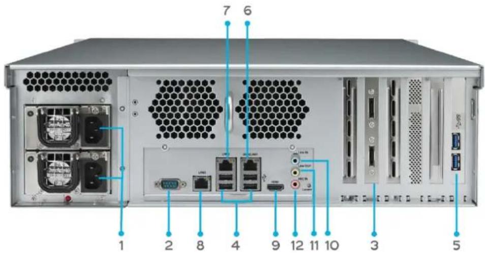
text_image
1 2 8 4 9 12 11 10 3 5 7 6| Back Panel | |
| Item | Description |
| 1.Power Connector | • Connect the included power cords to these connectors |
| 2.Serial Port | • This port is for external UPS device |
| 3.eSATA Port | • eSATA port for high-speed storage expansion |
| 4.USB Port | • USB 2.0 port for compatible USB devices, such as USB disks, and USB printers |
| 5.USB Port | • USB 3.0 port for compatible USB devices. |
| 6.WAN/LAN1 Port | • WAN/LAN1 port for connecting to an Ethernet network through a switch or router |
| 7.LAN2 Port | • LAN2 port for connecting to an Ethernet network through a switch or router |
| 8.LAN3 Port | • LAN3 port for HA connecting. |
| 9.HDMI Port | • For Video/Audio out |
| 10.Line in | • For Audio in |
| 11. Line out | • For Audio out |
| 12. Mic input | • Microphone input |
N6850:
The N6850 rear panel features ports and connectors.
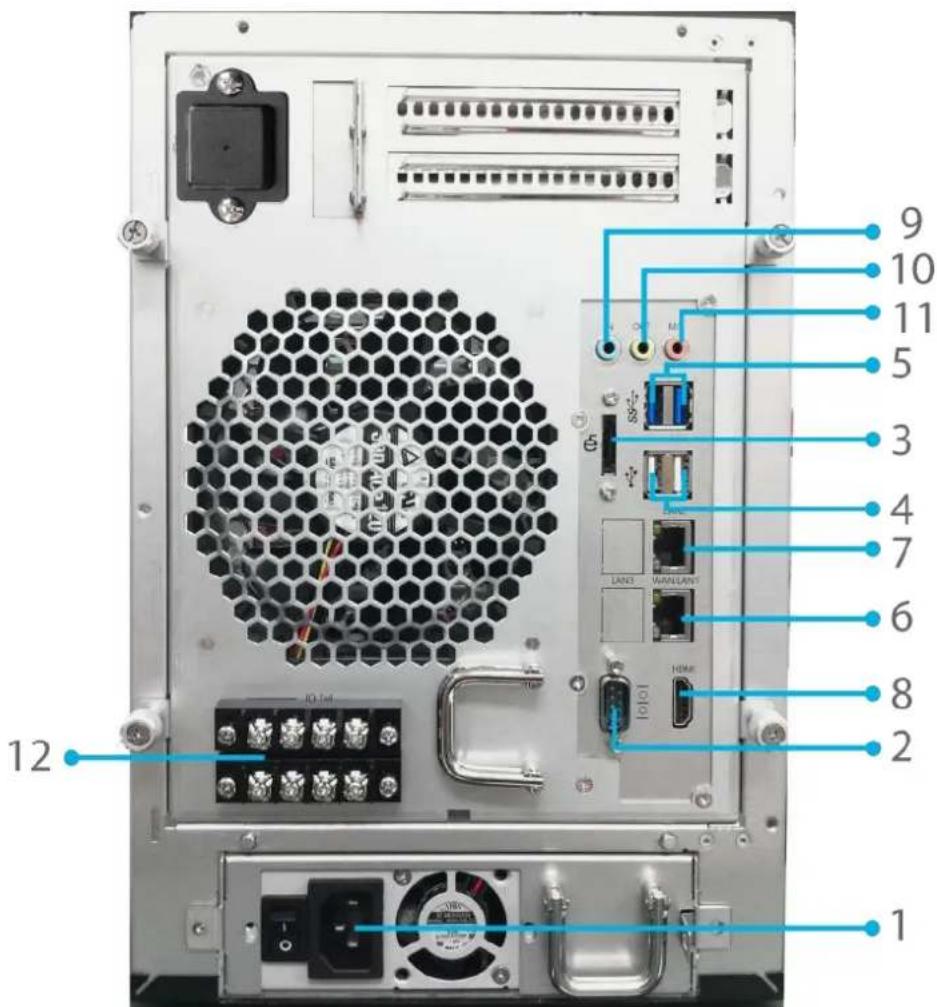
text_image
12 1 2 8 6 7 4 3 5 11 10 9 M LAN3 WARRANTY HDMI 10/14 I/O| Back Panel | |
| Item | Description |
| 1.Power Connector | Connect the included power cords to these connectors |
| 2.Serial Port | This port is for external UPS device |
| 3.eSATA Port | eSATA port for high-speed storage expansion |
| 4.USB Port | USB 2.0 port for compatible USB devices, such as USB disks, and USB printers |
| 5.USB Port | USB 3.0 port for compatible USB devices. |
| 6.WAN/LAN1 Port | WAN/LAN1 port for connecting to an Ethernet network through a switch or router |
| 7.LAN2 Port | LAN2 port for connecting to an Ethernet network through a switch or router |
| 8.HDMI Port | For Video/Audio out |
| 9.Line in | For Audio in |
| 10. Line out | For Audio out |
| 11. Mic input | Microphone input |
| 12. User GPIO | Could define each GPIO (0~7) and implement its own functionality. |
N8850:
The N8850 rear panel features ports and connectors.
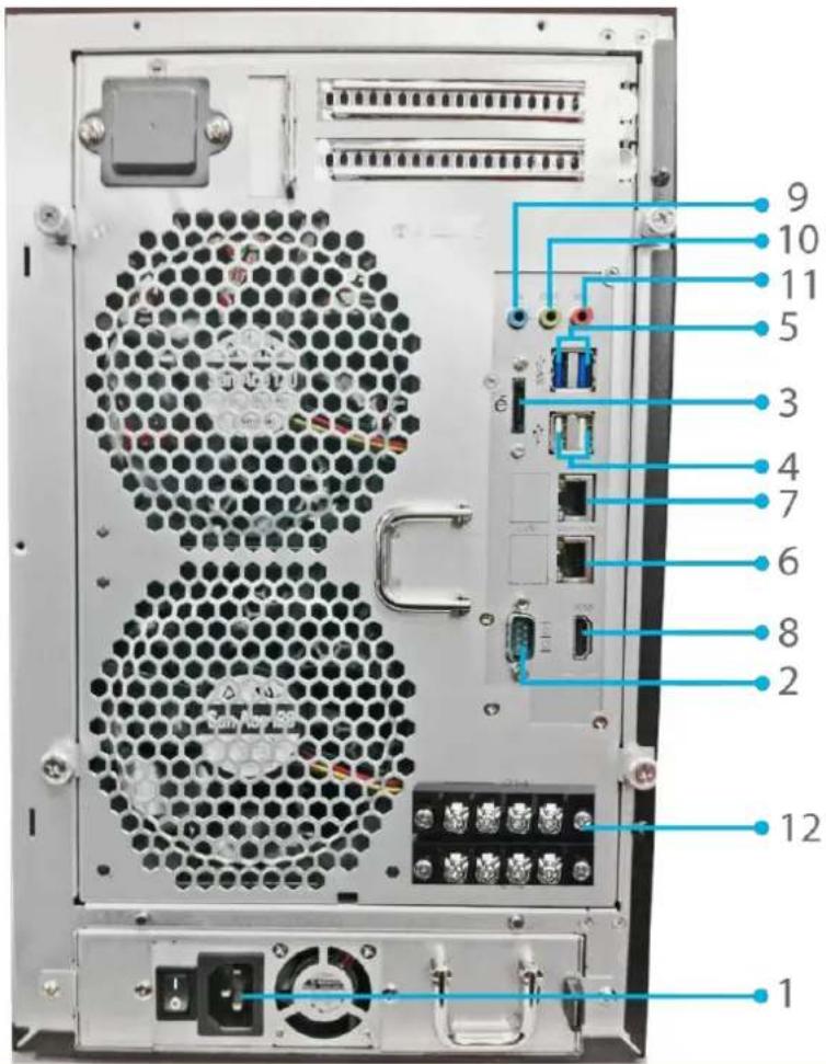
text_image
9 10 11 5 3 4 7 6 8 2 12 1| Back Panel | |
| Item | Description |
| 1.Power Connector | Connect the included power cords to these connectors |
| 2.Serial Port | This port is for external UPS device |
| 3.eSATA Port | eSATA port for high-speed storage expansion |
| 4.USB Port | USB 2.0 port for compatible USB devices, such as USB disks, and USB printers |
| 5.USB Port | USB 3.0 port for compatible USB devices. |
| 6.WAN/LAN1 Port | WAN/LAN1 port for connecting to an Ethernet network through a switch or router |
| 7.LAN2 Port | LAN2 port for connecting to an Ethernet network through a switch or router |
| 8.HDMI Port | For Video/Audio out |
| 9.Line in | For Audio in |
| 10. Line out | For Audio out |
| 11. Mic input | Microphone input |
| 12. User GPIO | Could define each GPIO (0~7) and implement its own functionality. |
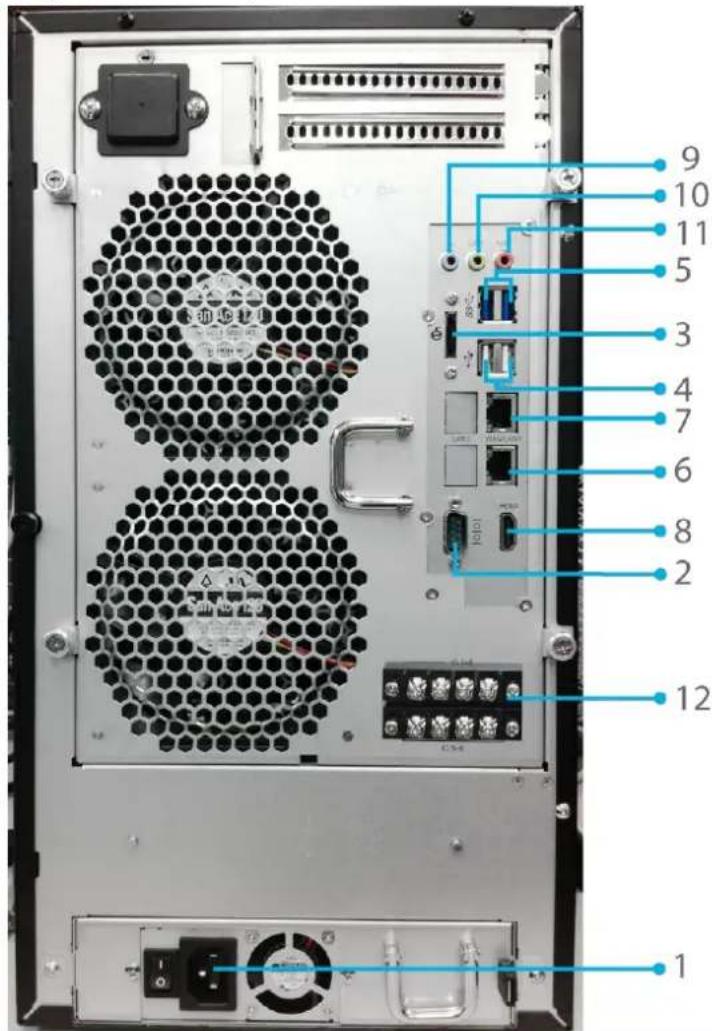
N10850:
The N10850 rear panel features ports and connectors.
text_image
Back panel diagram of a computer drive with numbered labels pointing to ports and connectors| Back Panel | |
| Item | Description |
| 1.Power Connector | Connect the included power cords to these connectors |
| 2.Serial Port | This port is for external UPS device |
| 3.eSATA Port | eSATA port for high-speed storage expansion |
| 4.USB Port | USB 2.0 port for compatible USB devices, such as USB disks, and USB printers |
| 5.USB Port | USB 3.0 port for compatible USB devices. |
| 6.WAN/LAN1 Port | WAN/LAN1 port for connecting to an Ethernet network through a switch or router |
| 7.LAN2 Port | LAN2 port for connecting to an Ethernet network through a switch or router |
| 8.HDMI Port | For Video/Audio out |
| 9.Line in | For Audio in |
| 10.Line out | For Audio out |
| 11.Mic input | Microphone input |
| 12.User GPIO | Could define each GPIO (0~7) and implement its own functionality. |
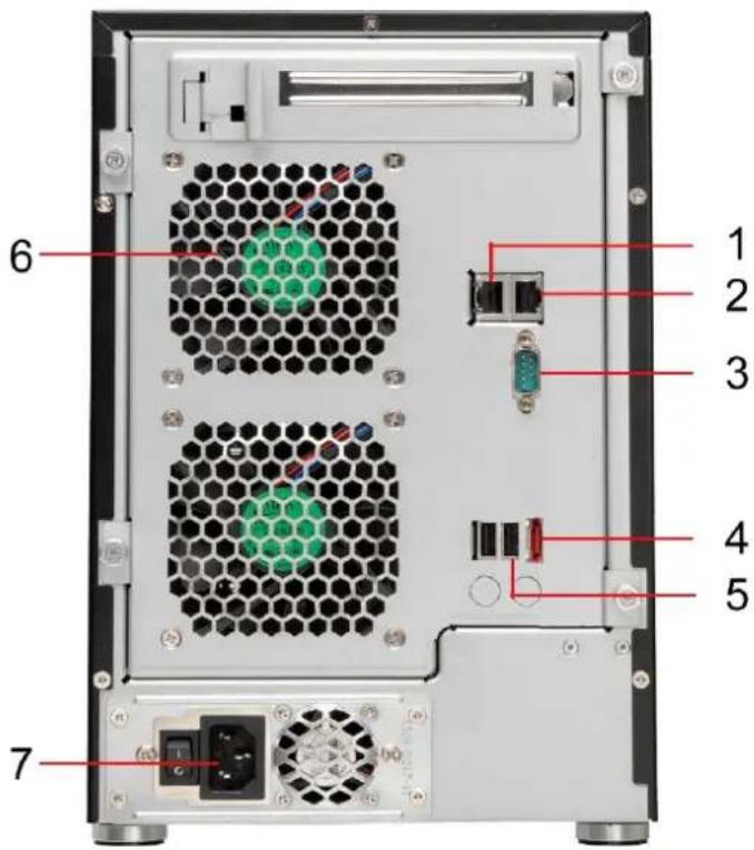
N7700PRO V2:
The N7700PRO V2 rear panel features ports and connectors.
text_image
1 2 3 4 5 6 7| Back Panel | |
| Item | Description |
| 1.LAN2 Port | • LAN2 port for connecting to a local Ethernet network through a switch or router. |
| 2.WAN/LAN1 Port | • WAN/LAN1 port for connecting to an Ethernet network through a switch or router. |
| 3.Serial Port | • This port is for an external UPS device. |
| 4.eSATA Port | • eSATA port for high-speed storage expansion. |
| 5.USB Port | • USB 2.0 port for compatible USB devices, such as USB disks, and USB printers. |
| 6.System Fan | • System fan that exhausts heat from the unit. |
| 7.Power Connector | • Connect the included power cord to this connector. |
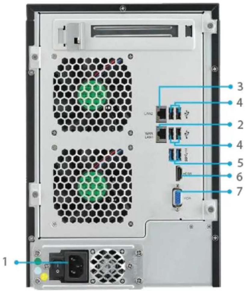
The N7710 series rear panel features ports and connectors.
text_image
LAN2 LAN1 VDA H108 3 4 2 4 5 6 7 1| Back Panel | |
| Item | Description |
| 1.Power Connector | Connect the included power cords to these connectors |
| 2.WAN/LAN1 Port | WAN/LAN1 port for connecting to an Ethernet network through a switch or router |
| 3.LAN2 Port | LAN2 port for connecting to an Ethernet network through a switch or router |
| 4.USB Port | USB 2.0 port for compatible USB devices, such as USB disks, and USB printers |
| 5.USB Port | USB 3.0 port for compatible USB devices, such as USB disks, and USB printers |
| 6.HDMI Port | For Video/Audio out |
| 7.VGA Port | For Video out |
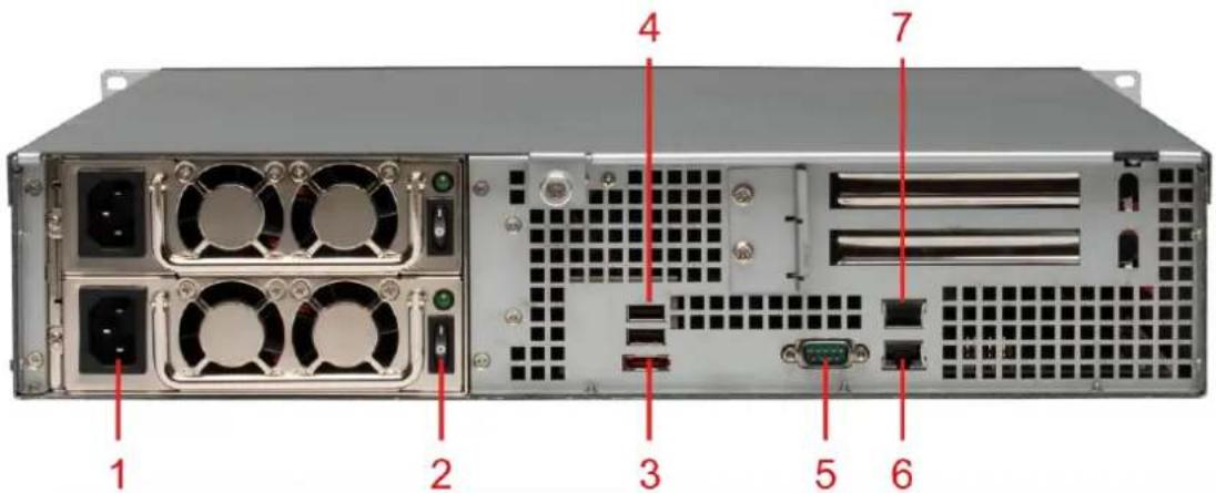
N8800PRO V2:
The N8800PRO V2 rear panel features ports and connectors.
text_image
1 2 3 4 5 6 7| Back Panel | |
| Item | Description |
| 1.Power Connector | Connect the included power cords to these connectors |
| 2.Power Switch | Switch for power supply |
| 3.eSATA Port | eSATA port for high-speed storage expansion |
| 4.USB Port | USB 2.0 port for compatible USB devices, such as USB disks, and USB printers |
| 5.Serial Port | This port is for external UPS device |
| 6.WAN/LAN1 Port | WAN/LAN1 port for connecting to an Ethernet network through a switch or router |
| 7.LAN2 Port | WAN/LAN1 port for connecting to an Ethernet network through a switch or router |
N8810U series/N8880U-10G:
The N8810U series rear panel features ports and connectors.
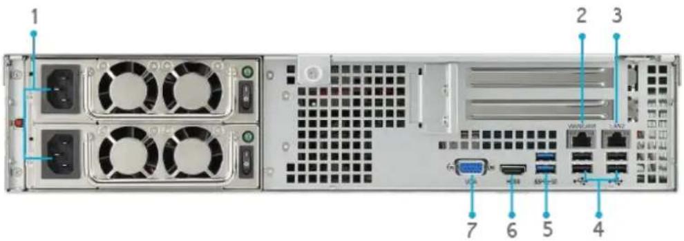
text_image
1 2 3 7 6 5 4| Back Panel | |
| Item | Description |
| 1.Power Connector | • Connect the included power cords to these connectors |
| 2. WAN/LAN1 Port | • WAN/LAN1 port for connecting to an Ethernet network through a switch or router |
| 3. LAN2 Port | • LAN2 port for connecting to an Ethernet network through a switch or router |
| 4.USB Port | • USB 2.0 port for compatible USB devices, such as USB disks, and USB printers |
| 5.USB Port | • USB 344.0 port for compatible USB devices, such as USB disks, and USB printers |
| 6.HDMI Port | • For Video/Audio out |
| 7.VGA Port | • For Video out |
N5550:
The N5550 rear panel features ports and connectors.
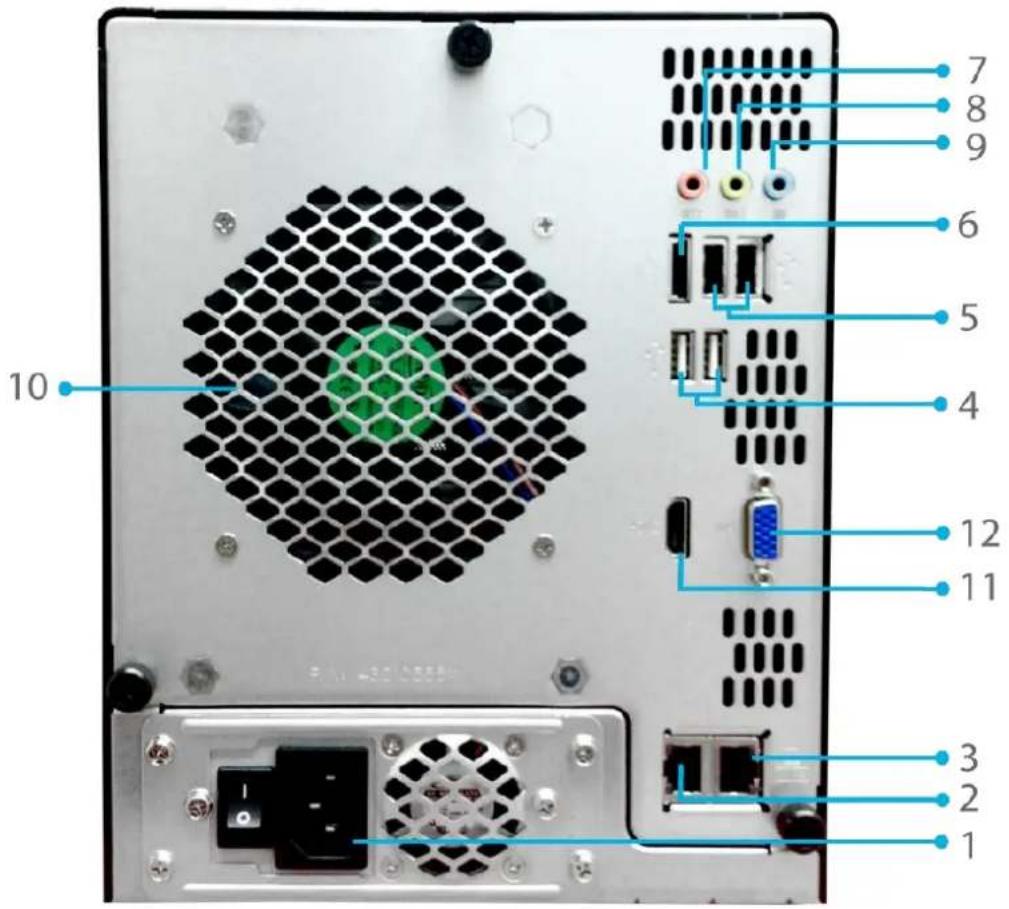
text_image
10 7 8 9 6 5 4 12 11 3 2 1| Back Panel | |
| Item | Description |
| 1.Power Connector | Connect the included power cords to these connectors |
| 2.WAN/LAN1 Port | WAN/LAN1 port for connecting to an Ethernet network through a switch or router |
| 3.LAN2 Port | LAN2 port for connecting to an Ethernet network through a switch or router |
| 4.USB Port | USB 2.0 port for compatible USB devices, such as USB disks, and USB printers |
| 5.USB Port | USB 2.0 port for compatible USB devices. |
| 6.eSATA Port | eSATA port for high-speed storage expansion |
| 7.Line in | For Audio in |
| 8.Line out | For Audio out |
| 9.Mic input | Microphone input |
| 10.System Fan | System fan that exhausts heat from the unit. |
| 11.HDMI Port | For Video/Audio out |
| 12.VGA Port | For Video out |
N5810/N5810PRO:
The N5810/N5810PRO rear panel features ports and connectors.
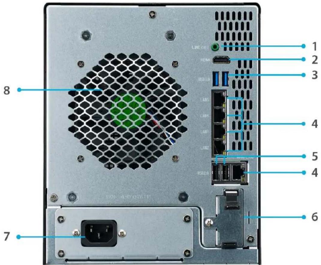
text_image
LINE 00 HDMI USB1.0 LAN5 LAN4 LAN3 LAN2 USB2.0 LINE 00 1 2 3 4 5 4 6 7 8| Back Panel | |
| Item | Description |
| 1. Line out | For Audio out |
| 2.HDMI Port | For Video/Audio out |
| 3.USB Port | USB 3.0 port for compatible USB devices, such as USB disks, and USB printers |
| 4. WAN/LAN1/LAN2/LAN3/LAN4/LAN5 Port | WAN/LAN1/LAN2/LAN3/LAN4/LAN5 port for connecting to an Ethernet network through a switch or router |
| 5.USB Port | USB 2.0 port for compatible USB devices. |
| 6.UPS Battery slot (N5810PRO) | For UPS Battery |
| 7.Power Connector | Connect the included power cords to these connectors |
| 8.System Fan | System fan that exhausts heat from the unit. |
N4510U-R:
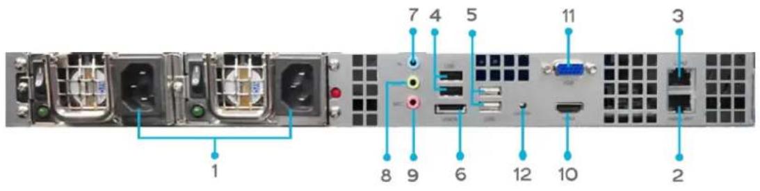
text_image
1 7 4 5 11 3 8 9 6 12 10 2| Back Panel | |
| Item | Description |
| 1.Power Connector | Connect the included power cords to these connectors |
| 2. WAN/LAN1 Port | WAN/LAN1 port for connecting to an Ethernet network through a switch or router |
| 3. LAN2 Port | LAN2 port for connecting to an Ethernet network through a switch or router |
| 4.USB Port | USB 2.0 port for compatible USB devices, such as USB disks, and USB printers |
| 5.USB Port | USB 2.0 port for compatible USB devices. |
| 6.eSATA Port | eSATA port for high-speed storage expansion |
| 7.Line in | For Audio in |
| 8. Line out | For Audio out |
| 9. Mic input | Microphone input |
| 10.HDMI Port | For Video/Audio out |
| 11.VGA Port | For Video out |
| 12. Locator LED | Identifies each NAS within a rack mount configuration. |
N4510U-S:
The rear panel of the N4510U-S is similar to the N4510U-R, but with a single power connector:
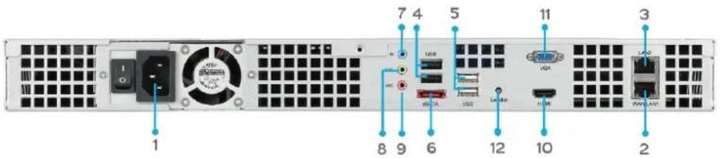
text_image
1 7 4 5 11 3 8 9 6 12 10 2N4510U PRO-R:
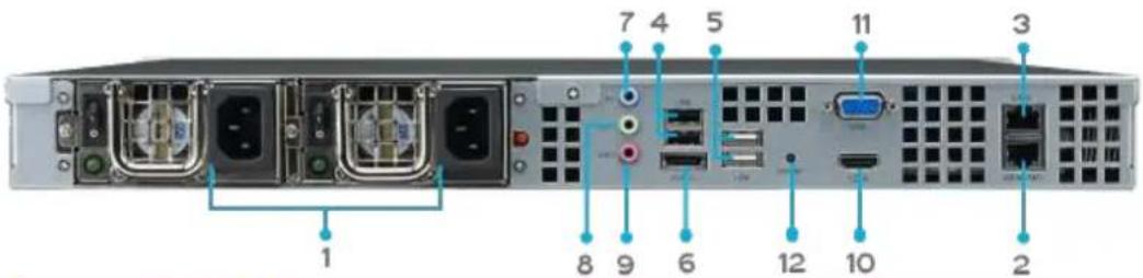
text_image
1 2 3 4 5 6 7 8 9 10 11 12| Back Panel | |
| Item | Description |
| 1.Power Connector | • Connect the included power cords to these connectors |
| 2. WAN/LAN1 Port | • WAN/LAN1 port for connecting to an Ethernet network through a switch or router |
| 3. LAN2 Port | • LAN2 port for connecting to an Ethernet network through a switch or router |
| 4.USB Port | • USB 2.0 port for compatible USB devices, such as USB disks, and USB printers |
| 5.USB Port | • USB 2.0 port for compatible USB devices. |
| 6.eSATA Port | • eSATA port for high-speed storage expansion |
| 7.Line in | • For Audio in |
| 8. Line out | • For Audio out |
| 9. Mic input | • Microphone input |
| 10.HDMI Port | • For Video/Audio out |
| 11.VGA Port | • For Video out |
| 12. Locator LED | • Identifies each NAS within a rack mount configuration. |
N4510U PRO-S:
The rear panel of the N4510U PRO-S is similar to the N4510U PRO-R, but with a single power connector:
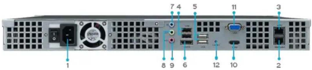
text_image
1 2 3 4 5 6 7 8 9 10 11 12N7510:
The N7510 rear panel features ports and connectors.
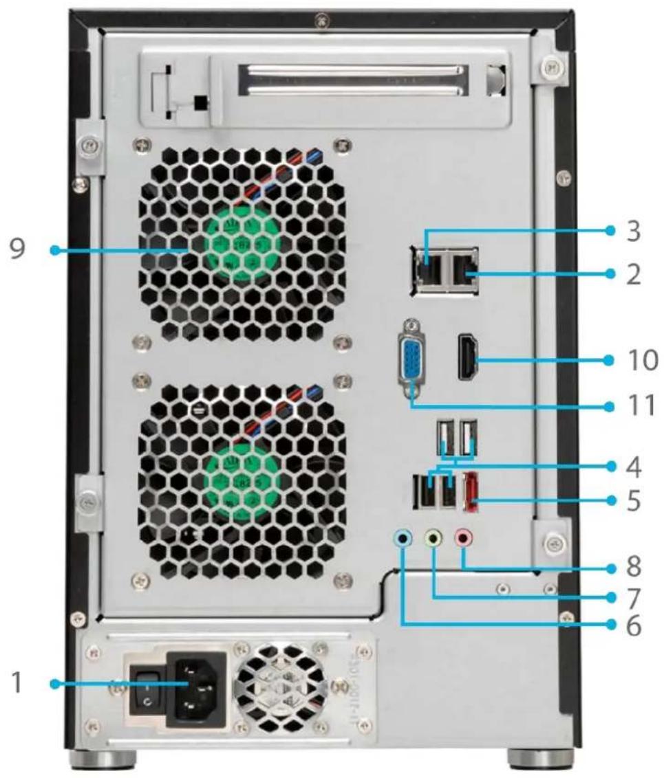
text_image
9 1 3 2 10 11 4 5 8 7 6 1| Back Panel | |
| Item | Description |
| 1.Power Connector | Connect the included power cords to these connectors |
| 2. WAN/LAN1 Port | WAN/LAN1 port for connecting to an Ethernet network through a switch or router |
| 3. LAN2 Port | LAN2 port for connecting to an Ethernet network through a switch or router |
| 4.USB Port | USB 2.0 port for compatible USB devices, such as USB disks, and USB printers |
| 5.eSATA Port | eSATA port for high-speed storage expansion |
| 6.Line in | For Audio in |
| 7. Line out | For Audio out |
| 8. Mic input | Microphone input |
| 9.System Fan | System fan that exhausts heat from the unit. |
| 10.HDMI Port | For Video/Audio out |
| 11.VGA Port | For Video out |
Chapter 2: Hardware Installation
Overview
Your Thecus IP storage is designed for easy installation. To help you get started, the following chapter will help you quickly get your Thecus IP storage up and running. Please read it carefully to prevent damaging your unit during installation.
Before You Begin
Before you begin, be sure to take the following precautions:
- Read and understand the Safety Warnings outlined in the beginning of the manual.
- If possible, wear an anti-static wrist strap during installation to prevent static discharge from damaging the sensitive electronic components on the Thecus IP storage.
- Be careful not to use magnetized screwdrivers around the Thecus IP storage's electronic components.
Cable Connections
To connect the Thecus IP storage product to your network, follow the steps below:
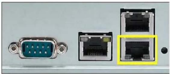
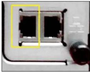
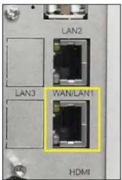
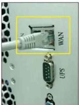
- Connect an Ethernet cable from your network to the WAN/LAN1 port on the back panel of the Thecus IP storage.
natural_image
Close-up of electronic device ports including a green VGA, black Ethernet, and two black Ethernet connectors with highlighted (no text or symbols visible)▲ N12000 series/N16000 series/N8900 series
natural_image
Close-up of a device with two black square components and a cylindrical connector (no visible text or symbols)▲N5550 WAN/LAN1 port
WAN/LAN1 port
text_image
LAN2 LAN3 WAN/LAN1 HDMI▲ N6850/N8850/N10850
WAN/LAN1 port
text_image
WAN UPSnatural_image
Close-up of a white RJ4 connector inserted into a black socket, with no visible text or symbols on the socket itself.N8800PRO V2/N8810U
series/N8880U-10G
WAN/LAN1 port
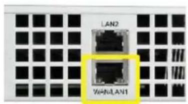
text_image
LAN2 WANLAN1▲ N4510U/N4510U PRO
WAN/LAN1 port
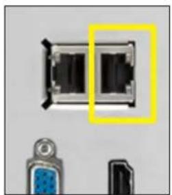
natural_image
Close-up of a black rectangular electronic component with two internal slots, alongside two connected connectors (no visible text or symbols)▲ N7510/N7710
natural_image
Close-up of a network device showing Ethernet ports and LAN2/LAN1 labels (no readable text beyond labels)▲ N5810/N5810PRO
WAN/LAN1 port
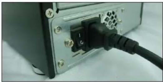
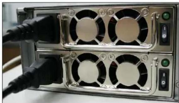
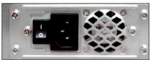
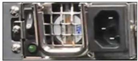
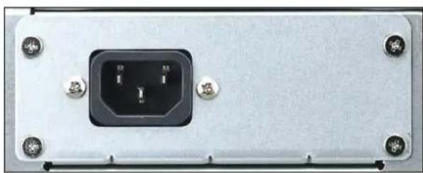
- Connect the provided power cord into the universal power socket on the back panel. Plug the other end of the cord into a surge protector socket.
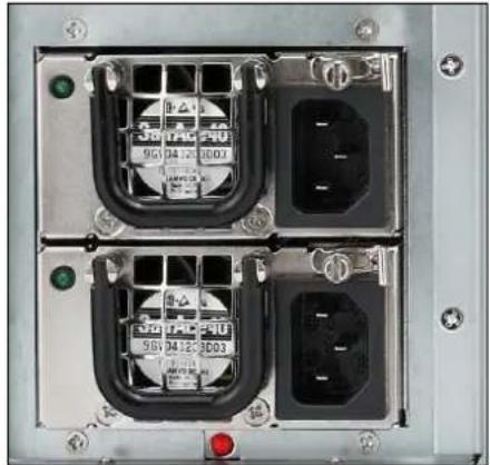
natural_image
Close-up of an electronic control panel with four ports and indicator lights (no readable text or symbols)▲ N12000 series/N16000 series/N8900 series power socket
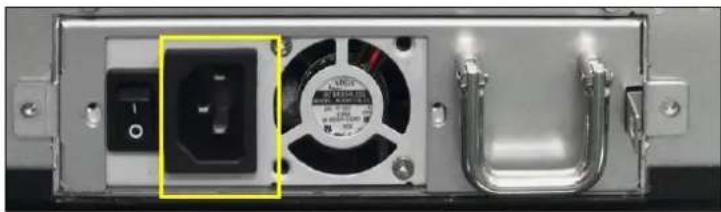
natural_image
Close-up of a computer power outlet with a black socket and fan (no visible text or symbols)▲ N6850/N8850/N10850 power socket
natural_image
Close-up of a black cable inserted into a device rear panel with an attached black socket (no visible text or symbols)▲ N7700PRO V2 /N7710 series/N7510/
N7770-10G power socket
natural_image
Close-up of a server rack with multiple fans and connected cables (no visible text or labels)▲ N8800PRO V2/N8810U/N8880U-10G series
power socket
natural_image
Close-up of a metallic electronic device rear panel showing a black socket, a grid-patterned vent, and screws (no visible text or symbols)▲ N5550 power socket
natural_image
Close-up of a mechanical device interior with internal components and no visible text or symbols▲ N4510U/N4510U PRO power socket
natural_image
Close-up of a metallic electronic device front panel with a black socket and four screws (no visible text or symbols)▲ N5810/N5810PRO power socket
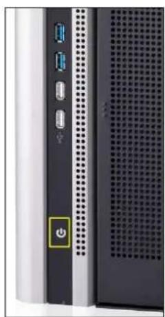
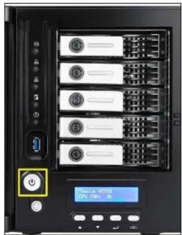
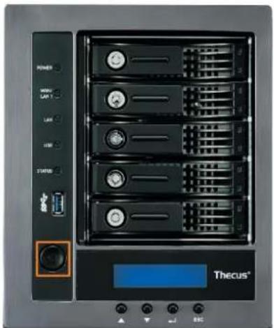
- Press the power button on the Front Panel to boot up the Thecus IP storage.

text_image
MUTE RST LAN Error BUSY PWR Locator▲ N12000 series/N16000 series/N8900 series power button
natural_image
Front view of a server rack with ports and a power button (no visible text or symbols)▲N6850/N8850/N10850 power button
text_image
Thicus MC500 CPU: 786.3K▲N5550power button
natural_image
Front view of a Thecus® server rack unit with multiple drive bays and control buttons (no readable text beyond labels)▲N5810/N5810PRO power button
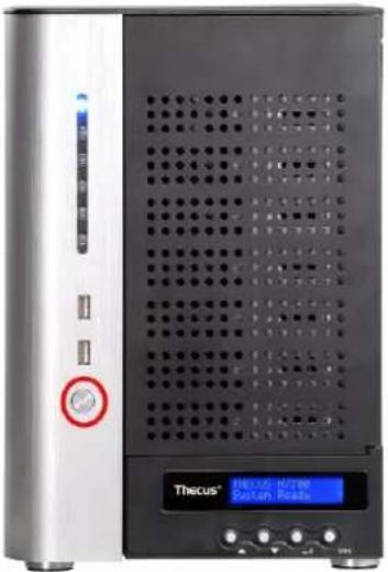
natural_image
Front view of a Thecus® H270M System Interface device with control panel and indicator lights (no readable text or symbols on main body)▲ N7700PRO V2/N7710 series/ N7510/N7770-10G power button
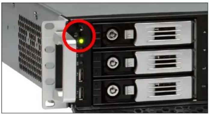
natural_image
Front view of a server rack with a highlighted drive (no visible text or labels)▲ N8800PRO V2/N8810U series/N8880U-10G power button
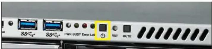
text_image
or SS SS PWR BUSY Error LAI RST MUTE▲ N4510U power button
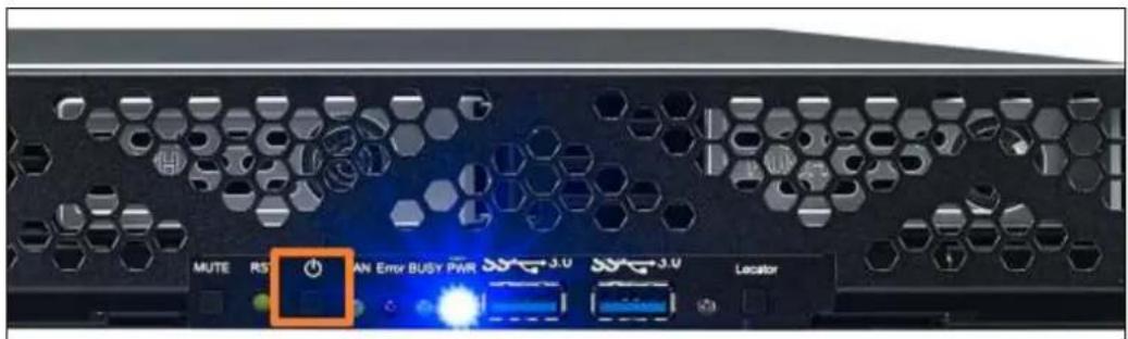
text_image
MUTE RS AN Error BUSY PWR 3.0 3.0 Locator▲ N4510UPRO powerbutton
Chapter 3: First Time Setup
Overview
Once the hardware is installed, physically connected to your network, and powered on, you can configure the Thecus IP storage so that it is accessible to your network users. There are two ways to set up your Thecus IP storage: using the Thecus Setup Wizard or the LCD display. Follow the steps below for initial software setup.
Thecus Setup Wizard
The handy Thecus Setup Wizard makes configuring Thecus IP storage a snap. To configure the Thecus IP storage using the Setup Wizard, perform the following steps:
- Insert the installation CD into your CD-ROM drive (the host PC must be connected to the network).
- The Setup Wizard should launch automatically. If not, please browse your CD-ROM drive and double click on Setup.exe.
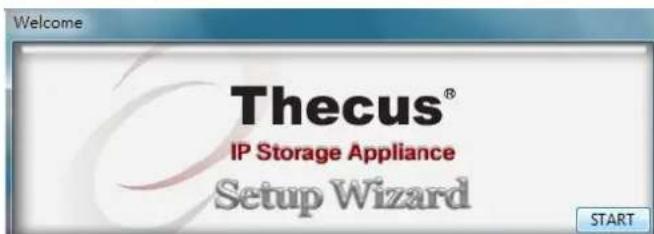
text_image
Welcome Thecus® IP Storage Appliance Setup WizardNOTE
For MAC OS X users, double click on Thecus Setup Wizard .dmg file.
- The Setup Wizard will start and automatically detect all Thecus storage devices on your network. If none are found, please check your connection and refer to Chapter 7: Troubleshooting for assistance.
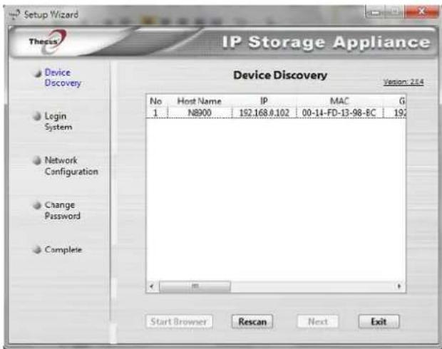
text_image
Setup Wizard Thesis IP Storage Appliance Device Discovery Version: 2.4 No Host Name IP MAC G 1 N8900 192.168.0.102 00-14-FD-13-98-BC 192 Start Browser Rescan Next Exit-
Select the Thecus IP storage that you like to configure.
-
Login with the administrator account and password. The default account and password are both "admin".
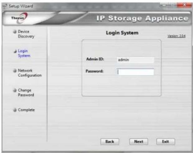
text_image
Setup Wizard Thecus IP Storage Appliance Login System Version 104 Admin ID: admin Password: Back Next Exit- Name your Thecus IP storage and configure the network IP address. If your switch or router is configured as a DHCP Server, configuring the Thecus IP storage to automatically obtain an IP address is recommended. You may also use a static IP address and enter the DNS Server address manually.
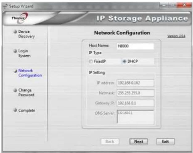
text_image
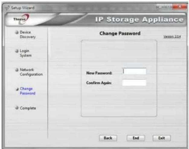
Setup Wizard Therix IP Storage Appliance Network Configuration Version 2.04 Host Name: NB900 IP Type FixedIP DHCP IP Setting IP address: 192.168.0.102 Netmask: 255.255.255.0 Gateway IP: 192.168.0.1 DNS Server: 192.168.0.1 Back Next Exit- Change the default administrator password.
text_image
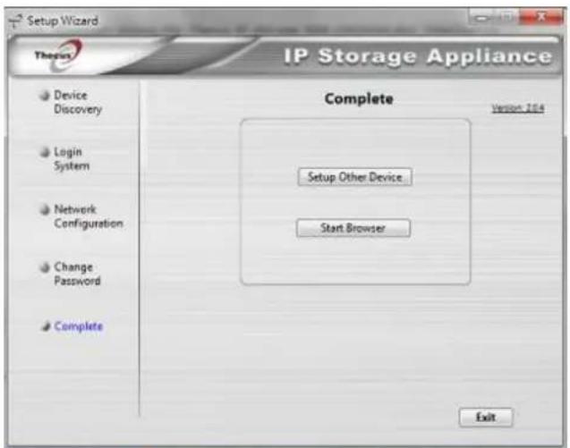
Setup Wizard Therpin IP Storage Appliance Change Password Version 2014 Device Discovery Login System Network Configuration Change Password Complete New Password: Confirm Again: Back End Exit- Finished! Access the Thecus IP storage Web Administrator Interface by pressing the Start Browser button. You can also configure another Thecus IP storage at this point by clicking the Setup Other Device button. Press Exit to exit the wizard.
text_image
Setup Wizard Therex IP Storage Appliance Complete Version 10.4 Setup Other Device Start Browser ExitNOTE
The Thecus Setup Wizard is designed for installation on systems running Windows XP/2000/vista/7 or Mac OSX or later. Users with other operating systems will need to install the Thecus Setup Wizard on a host machine with one of these operating systems before using the unit.
LCD Operation (N7700PRO V2/N8800PRO V2/ N7710 series/N8810U
series/N5550/N5810/N5810PRO/N4510U
series/N7510/N7770-10G/N8880U-10G)
The mentioned models above are equipped with an LCD on the front for easy status display and setup. There are four buttons on the front panel to control the LCD functions.
LCD Controls
Use the Up (▲), Down (▼), Enter (←) and Escape (ESC) keys to select various configuration settings and menu options for Thecus IP storage configuration.
The following table illustrates the keys on the front control panel:
LCD Controls
| Icon | Function | Description |
| ▲ | Up Button | Select the previous configuration settings option. |
| ▼ | Down Button | USB copy confirmation display. |
| ↓ | Enter | Enter the selected menu option, sub-menu, or parameter setting. |
| ESC | Escape | Escape and return to the previous menu. |
There are two modes of operation for the LCD: Display Mode and Management Mode.
Display Mode
During normal operation, the LCD will be in Display Mode.
| Display Mode | |
| Item | Description |
| Host Name | Current host name of the system. |
| WAN/LAN1 | Current WAN/LAN1 IP setting. |
| LAN2 | Current LAN2 IP setting. |
| Link Aggregation | Current Link Aggregation status |
| System Fan1 | Current system fan1 status. |
| System Fan2 | Current system fan2 status. |
| CPU Fan | Current CPU fan status |
| 2009/05/22 12:00 | Current system time. |
| Disk Info | Current status of disk slot has been installed |
| RAID | Current RAID status. |
The Thecus IP storage will rotate these messages every one-two seconds on the LCD display.
USB Copy
The USB Copy function enables you to copy files stored on USB devices such as USB disks and digital cameras to the Thecus IP storage by press button. To use USB copy, follow the steps below:
- Plug your USB device into an available USB port on the Front end.
- In Display Mode, press the Down Button (▼).
- The LCD will display "USB Copy?"
- Press Enter (↓) and the Thecus IP storage will start copying USB disks connected to the front USB port.
- All of data will be copied into system folder named "USB copy".
Management Mode
During setup and configuration, the LCD will be in Management Mode.
To enter into Management Mode, press Enter (⊥) and an "Enter Password" prompt will show on the LCD.
At this time, the administrator has to enter the correct LCD password. System will check whether the correct LCD password has been entered. The default LCD password is "0000". If correct password is entered, you will enter into the Management Mode menu.
| Management Mode | |
| Item | Description |
| WAN/LAN1 Setting | IP address and netmask of your WAN/LAN1 ports. |
| LAN2 Setting | IP address and netmask of your LAN2 ports. |
| Link Agg, Setting | Select Load Balance, 802.3ad or Failover. |
| Change Admin Passwd | Change administrator's password for LCD operation. |
| Reset to Default | Reset system to factory defaults. |
| Exit | Exit Management Mode and return to Display Mode. |
NOTE
You can also change your LCD password using the Web Administration Interface by navigating to System Management > Administrator Password. For more on the Web Administration Interface, see Chapter 4: System Management.
OLED Operation(Does not apply to the N7700PRO V2/N8800PRO V2/N7710 series/N8810U series/N5550/N5810/N5810PRO/N4510U series/N7510/N7770-10G/N8880U-10G)
OLED Operation
The Thecus IP storage is equipped with an OLED on the front for easy status display and setup. There are four buttons on the front panel to control the OLED functions.
OLED Controls
Use the Up (▲), Down (▼), Enter (←) and Escape (ESC) keys to select various configuration settings and menu options for Thecus IP storage configuration.
The following table illustrates the keys on the front control panel:
OLED Controls
| Icon | Function | Description |
| ▲ | Up Button | Select the previous configuration settings option. |
| ▼ | Down Button | USB copy confirmation display. |
| ↓ | Enter | Enter the selected menu option, sub-menu, or parameter setting. |
| ESC | Escape | Escape and return to the previous menu. |
There are two modes of operation for the OLED: Display Mode and Management Mode.
Display Mode
During normal operation, the OLED will be in Display Mode.
| Display Mode | |
| Item | Description |
| Host Name | Current host name of the system. |
| WAN/LAN1 | Current WAN/LAN1 IP setting. |
| LAN2 | Current LAN2 IP setting. |
| Link Aggregation | Current Link Aggregation status |
| System Fan | Current system fan status. |
| CPU Fan | Current CPU fan status |
| 2009/05/22 12:00 | Current system time. |
| RAID | Current RAID status. |
The Thecus IP storage will rotate these messages every one-two seconds on the OLED display.
USB Copy
The USB Copy function enables you to copy files stored on USB devices such as USB disks and digital cameras to the Thecus IP storage with a press of a button. To use USB copy, follow the steps below:
- Plug your USB device into an available USB port on the Front Panel.
-
In Display Mode, press the Enter (↓).
-
The LCD will display "USB Copy?"
- Press Enter ( ) and the Thecus IP storage will start copying USB disks connected to the front USB port. The LCD will display the USB copy progress and results.
Typical Setup Procedure
From the Web Administration Interface, you can begin to setup your Thecus IP storage for use on your network. Setting up the Thecus IP storage typically follows the five steps outlined below.
For more on how to use the Web Administration Interface, see
Chapter 4: Web Administration Interface.
Step 1: Network Setup
From the Web Administration Interface, you can configure the network settings of the Thecus IP storage for your network. You can access the Network menu from the menu bar.
For details on how to configure your network settings, refer to
Chapter 4: System Network.
Step 2: RAID Creation
Next, administrators can configure their preferred RAID setting and build their RAID volume. You can access RAID settings from the menu bar of the Web Administration Interface by navigating to Storage Management > RAID Management.
For more information on configuring RAID, see
Chapter 4: Storage > RAID Management.
Don't know which RAID level to use? Find out more about the different RAID levels from Appendix B: RAID Basics.
Step 3: Create Local Users or Setup Authentication
Once the RAID is ready, you can begin to create local users for Thecus IP storage, or choose to setup authentication protocols such as Active Directory (AD).
For more on managing users, go to Chapter 4: User and Group Authentication.
For more information on configuring Active Directory, see
Chapter 4: User and Group Authentication > ADS Support.
For information about the benefits of Active Directory, see Appendix D: Active Directory Basics.
Step 4: Create Folders and Set Up ACLs
Once users are introduced into your network, you can begin to create various folders on the Thecus IP storage and control user access to each using Folder Access Control Lists.
More information on managing folders, see
Chapter 4: Storage Management > Share Folder.
To find out about configuring Folder Access Control Lists, see Chapter 4: Storage Management > Share Folder> Folder Access Control List (ACL).
Step 5: Start Services
Finally, you can start to setup the different services of Thecus IP storage for the users on your network. You can find out more about each of these services by clicking below:
SMB/CIFS
Apple File Protocol (AFP)
Network File System (NFS)
File Transfer Protocol (FTP)
iTunes Server
Printer Server
Chapter 4: System Administration
Overview
The Thecus IP storage provides an easily accessible Web Administration Interface. With it, you can configure and monitor the Thecus IP storage anywhere on the network.
Web Administration Interface
Make sure your network is connected to the Internet. To access Thecus IP storage Web Administration Interface:
- Type the Thecus IP storage IP address into your browser. (Default IP address is http://192.168.1.100)

text_image
ThecusOS™ Protect Your Status Secure Your Data To properly boost the Web Apps, as recommended you use OS History, Safe, or Google Claims. ©2018 LOGI version 6.0.1.2018NOTE
Your computer's network IP address must be on the same subnet as the Thecus IP storage. If the Thecus IP storage has default IP address of 192.168.1.100, your managing PC IP address must be 192.168.1.x, where x is a number between 1 and 254, but not 100.
- Login to the system using the administrator user name and password. The factory defaults are:
User Name: admin Password: admin
※ If you changed your password in the setup wizard, use the new password.
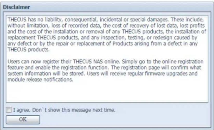
Once you are logged in as an administrator, the disclaimer page will appear as below. Please click the check box if you do not want to have this page displayed during the next login.
text_image
Disclaimer THECUS has no liability, consequential, incidental or special damages. These include, without limitation, loss of recorded data, the cost of recovery of lost data, lost profits and the cost of the installation or removal of any THECUS products, the installation of replacement THECUS products, and any inspection, testing, or redesign caused by any defect or by the repair or replacement of Products arising from a defect in any THECUS products. Users can now register their THECUS NAS online. Simply go to the online registration feature and enable the registration function. The registration page will confirm what system information will be stored. Users will receive regular firmware upgrades and module release notifications. I agree. Don't show this message next time. OKFollowing the disclaimer page, you will see the Web Administration Interface. From here, you can configure and monitor virtually every aspect of the Thecus IP storage from anywhere on the network.
My Favorite
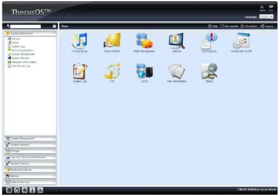
The user interface with "My Favorite" shortcut allows the user to designate often used items and have them display on the main screen area. The figure below displays system favorite functions.
text_image
ThecusOS™ Language Log System Information General Status System Log Online Registration Syslog Management System Monitor Hardware Information User Access Log Home iTunes Server Share Folders RAD Management General Notifications Scheduled On/Off System Log FTP SCD Disk Information Status System Management System Network Storage Year and Group Authentication Network Service Applications Server Backup External Devices THECUS IH800ECo V2.63.98.cmvAdministrators can add or remove favorite functions to My Favorites by right clicking the mouse on the menu tree.
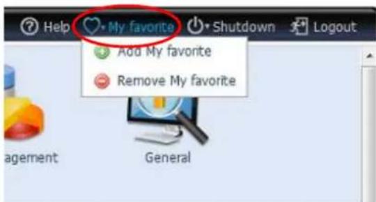
Another way the administrators can add favorite functions is by clicking the "Add Favorite" icon in each function screen. See the figure below with the red circled icon.
text_image
Help My favorite Shutdown Logout Add My favorite Remove My favorite Management GeneralTo return to the favorite screen, simply click "Home" located at the left hand corner of the main screen.

text_image
Home > System Information > General Product Information Manufacturer Thecus Product No UnpocurMenu Bar
The Menu Bar is where you will find all of the information screens and system settings of Thecus IP storage. The various settings are placed in the following groups on the menu bar:
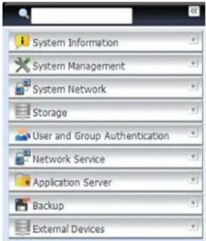
text_image
System Information System Management System Network Storage User and Group Authentication Network Service Application Server Backup External Devices| Menu Bar | |
| Item | Description |
| System Information | Current system status of the Thecus IP storage. |
| System Management | Various Thecus IP storage system settings and information. |
| System Network | Information and settings for network connections, as well as various services of the Thecus IP storage. |
| Storage | Information and settings for storage devices installed into the Thecus IP storage. |
| User and Group Authentication | Allows configuration of users and groups. |
| Network Service | Use the Network Service menu to make network service support settings. |
| Application Server | App and iTunes Server set-up of the Thecus IP storage. |
| Backup | Category of Backup Features setup of the Thecus IP storage. |
| External Devices | The Thecus IP storage supports printer server and UPS via USB interface. |
Moving your cursor over any of these items will display the dropdown menu selections for each group.
In the following sections, you will find detailed explanations of each function, and how to configure your Thecus IP storage.
Message Bar
You can get quick information about your system status by moving your mouse over these icons.
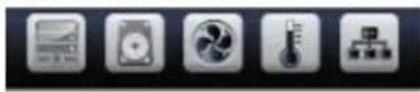
| Message Bar | ||
| Item | Status | Description |
 | RAID Information. | Display the status of created RAID volume. Click to go to RAID information page as short cut. |
 | Disks Information. | Display the status of disks installed in the system. Click to go to Disk information page as short cut. |
 | FAN. | Display system FAN Status. Click to go to System Status page as short cut. |
 | Temperature | Display system temperature, click to go to System Status page as shot cut. |
 | Network. | Green: Connection to the network is normal.Red: abnormal connection to the network |
Logout
Click to logout Web Administration Interface.
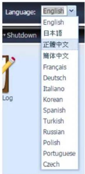
Language Selection
The Thecus IP storage supports multiple Languages,
- English
- Japanese
• Traditional Chinese - Simplified Chinese
- French
- German
- Italian
- Korean
- Spanish
- Turkish
- Russian
- Polish
- Portuguese
• Czech
text_image
Language: English English 日本語 正體中文 簡体中文 Français Deutsch Italiano Korean Spanish Turkish Russian Polish Portuguese CzechOn the menu bar, click Language and the selection list appears. This user interface will switch to the selected language for Thecus IP storage.
System Information
Information provides viewing on current Product info, System Status, Service Status and Logs.
The menu bar allows you to see various aspects of the Thecus IP storage. From here, you can discover the status of the Thecus IP storage, and also other details.
General
Once you login, you will first see the basic system Information screen providing Manufacturer, Product No., Firmware Version, and System Up Time information.

text_image
System Information General Status System Log Syslog Management System Monitor Hardware Information User Access Log
text_image
N4800Eco Manufacturer: Thecus Product No.: N4800Eco Firmware Version: 2.05.08.cdv Up Time: 6 Minutes| System Information | |
| Item | Description |
| Manufacturer | Displays the name of the system manufacturer. |
| Product No. | Shows the model number of the system. |
| Firmware version | Shows the current firmware version. |
| Up time | Displays the total run time of the system. |
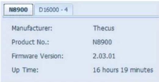
The Thecus N8900/N12000/N16000 series are supporting the addition of the JBOD device Thecus D16000 to expand storage capacity. From General in System Information, JBOD device info will be displayed if applicable.
text_image
N8900 D16000 - 4 Manufacturer: Thecus Product No.: N8900 Firmware Version: 2.03.01 Up Time: 16 hours 19 minutes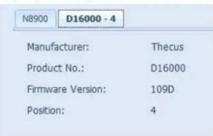
text_image
N8900 D16000 - 4 Manufacturer: Thecus Product No.: D16000 Firmware Version: 109D Position: 4Status
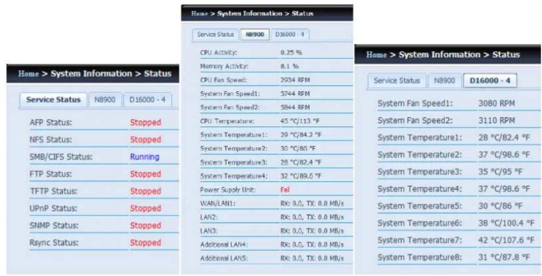
From the System Information menu, choose the Status item, System Service Status and HW Status screens appear. These screens provide basic system and service status information.
text_image
Home > System Information > Status Service Status NB900 D16000 - 4 CPU ACIVITY: 0.25 % Memory ACIVITY: 8.1 % CPU Fan Speed: 2934 RPM System Fan Speed1: 5744 RPM System Fan Speed2: 5844 RPM CPU Temperature: 45 °C/113 °F System Temperature1: 29 °C/84.2 °F System Temperature2: 30 °C/86 °F System Temperature3: 28 °C/82.4 °F System Temperature4: 32 °C/89.6 °F Power Supply Unit: Fail WAN/LAN1: RX: 0.0, TX: 0.0 MB/s LAN2: RX: 0.0, TX: 0.0 MB/s LAN3: RX: 0.0, TX: 0.0 MB/s Additional LAN4: RX: 0.0, TX: 0.0 MB/s Additional LAN5: RX: 0.0, TX: 0.0 MB/s Home > System Information > Status Service Status N8900 D16000 - 4 System Fan Speed1: 3080 RPM System Fan Speed2: 3110 RPM System Temperature1: 28 °C/82.4 °F System Temperature2: 37 °C/98.6 °F System Temperature3: 35 °C/95 °F System Temperature4: 37 °C/98.6 °F System Temperature5: 30 °C/86 °F System Temperature6: 38 °C/100.4 °F System Temperature7: 42 °C/107.6 °F System Temperature8: 31 °C/87.8 °FLogs
text_image
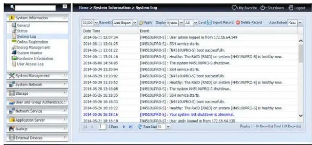
Home > System Information > System Log 10,000 Record(s) Auto Export Apply Display System All Level Export Record Delete Record Auto Refrads None Date Time Event 2014-06-11 13:07:34 [N4510UPRO-S] : User admin logged in from 172.16.64.149 2014-06-11 13:01:25 [N4510UPRO-S] : SSH service starts. 2014-06-11 13:01:22 [N4510UPRO-S] : [N4510UPRO-S] boot successfully. 2014-06-11 13:01:16 [N4510UPRO-S] : Healthy: The RAID [RAID] on system [N4510UPRO-S] is healthy now. 2014-06-06 14:54:05 [N4510UPRO-S] : The system N4510UPRO-S shutdown. 2014-05-29 11:20:04 [N4510UPRO-S] : SSH service starts. 2014-05-29 11:26:02 [N4510UPRO-S] : [N4510UPRO-S] boot successfully. 2014-05-29 11:19:52 [N4510UPRO-S] : Healthy: The RAID [RAID] on system [N4510UPRO-S] is healthy now. 2014-05-28 13:18:08 [N4510UPRO-S] : The system N4510UPRO-S shutdown. 2014-05-26 16:18:35 [N4510UPRO-S] : SSH service starts. 2014-05-26 16:18:33 [N4510UPRO-S] : [N4510UPRO-S] boot successfully. 2014-05-26 16:18:22 [N4510UPRO-S] : Healthy: The RAID [RAID] on system [N4510UPRO-S] is healthy now. 2014-05-26 16:18:16 [N4510UPRO-S] : Your system last shutdown is abnormal. 2014-05-21 18:16:10 [N4510UPRO-S] : User and loaned in from 172.16.64.139 Display 1 - 50 Record(s) Total 119 Record(s) System Information General Status System Log Online Registration Syslog Management System Monitor Hardware Information User Access Log System Management System Network Storage User and Group Authenticatic... Network Service Application Server Backup External DevicesFrom the System Information menu, choose the System Logs option and the System Logs screen will appear. This screen shows a history of system usage and important events such as disk status, network information, and system booting.
| Logs | |
| Item | Description |
| Number of records to export | This can be selected from a dropdown list to export the log(s) as a single file. |
| Export log option | This can be set to Auto Export or Auto Delete. |
| Log Type | The default logs displayed are for system events. From the dropdown list, administrators can choose from various formsof user access, such as AFP, Samba, etc.Note: Users need to enable the "User Access Log" service to view these details. |
| Log Level | ALL: Provides all log information including system, warning, and error messages.INFO: Shows information about system messages.WARNING: Shows only warning messages.ERROR: Shows only error messages. |
| Export Records | Export all logs to an external file. |
| Delete Records | Clear all log files. |
| Auto Refresh | Specify the auto refresh time interval. |
| The number of lines per page | Specify the desired number of lines to display per page. |
| Sort Ascending | Shows logs by date in ascending order. |
| Sort Descending | Shows logs by date in descending order. |
| |<< < > >>| | Use the forward ( > >>| ) and backward ( |<< < ) buttons to browse through the log pages. |
| () | Reload logs. |
text_image
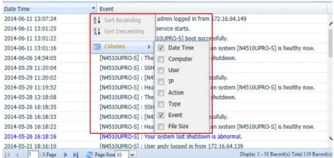
Date Time Event 2014-06-11 13:07:34 2014-06-11 13:01:25 2014-06-11 13:01:22 2014-06-11 13:01:16 2014-06-06 14:54:05 2014-05-29 11:20:04 2014-05-29 11:20:02 2014-05-29 11:19:52 2014-05-28 13:18:08 2014-05-26 16:18:35 2014-05-26 16:18:33 2014-05-26 16:18:22 2014-05-26 16:18:16 2014-05-21 18:16:10 Sort Ascending Sort Descending Columns [N4510UPRO-S] : The [N4510UPRO-S] : SSH [N4510UPRO-S] : [N4] [N4510UPRO-S] : Hea [N4510UPRO-S] : The [N4510UPRO-S] : SSH [N4510UPRO-S] : [N4] [N4510UPRO-S] : Hea admin logged in from .72.16.64.149 service starts. [10UPRO-S] boot successfully. ✓ Date Time Computer User IP Action Type ✓ Event File Size on system [N4510UPRO-S] is healthy now. shutdown. on system [N4510UPRO-S] is healthy now. shutdown. on system [N4510UPRO-S] is healthy now. on system [N4510UPRO-S] is healthy now. on system [N4510UPRO-S] is healthy now. Display 1 - 50 Record(s) Total 119 Record(s) Page Size 50Columns can also be added to display additional information about each event.
Syslog Management
Generates system log to be stored locally or remotely, it also can be chose to act as syslog server for all other devices.
These messages are stored on your NAS in: Nsync > log> messages.
Information can be obtained in two ways: locally and remotely.
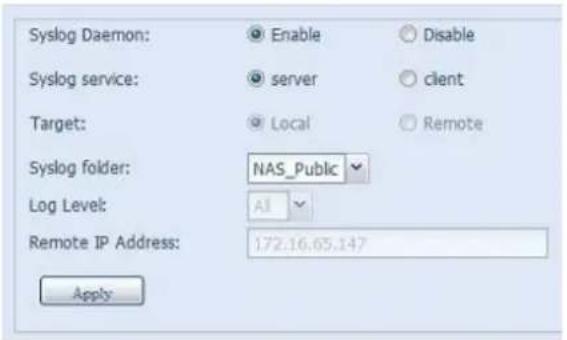
Configuration with syslog server:
text_image
Syslog Daemon: Enable Disable Syslog service: server client Target: Local Remote Syslog folder: NAS_Public Log Level: All Remote IP Address: 172.16.65.147 ApplyConfiguration with syslog client and target to store locally:
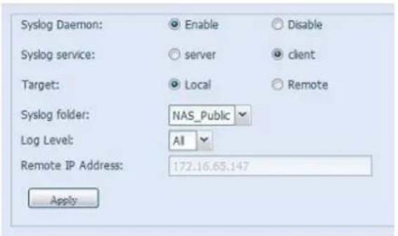
text_image
Syslog Daemon: Enable Disable Syslog service: server client Target: Local Remote Syslog folder: NAS_Public Log Level: All Remote IP Address: 172.16.65.147 ApplyConfiguration with syslog client and target to store remotely:
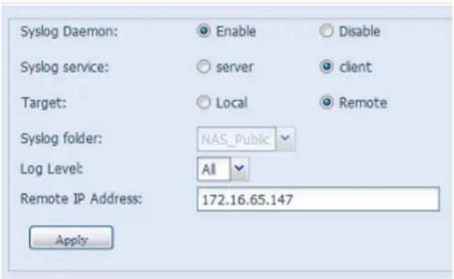
text_image
Syslog Daemon: Enable Disable Syslog service: server client Target: Local Remote Syslog folder: NAS_Public Log Level: All Remote IP Address: 172.16.65.147 ApplySee the following table for a detailed description of each item:
| Time | |
| Item | Description |
| Syslog Daemon | Enable/Disable syslog daemon. |
| Syslog service | If Server has been selected then associated syslog folder will be used to store all system logs from other NAS devices which has |
| assigned this system for syslog server as well as syslog of this server unit. It can be seen from associated syslog folder with files "error", "Information" and "warning".If client has been selected then "Local" or "Remotely" can be choose. | |
| Target | Choose Local, all system logs will be stored in an associated syslog folder filled in from next filed. And the syslog folder will have file "messages" to store all system logs. If Remotely has been selected, a syslog server is needed and an IP address is required. |
| Syslog folder | Select from a drop down share list, all of the system logs will be stored on it. This syslog folder is applied to "syslog server" or "syslog client" with "local" selected. |
| Log Level | The user can choose from 3 different levels. "All", "Warning/Error" or "Error". |
| Remote IP Address | Input the syslog server IP address if choose to store syslog info remotely. |
System Monitor
The system monitor is capable to monitor system status including CPU/memory utilization, fan/temperature status, network throughput and on-line user list in various protocols.
To monitor system status, simply click on "System Monitor" from the tree menu and the screen will appear as below.
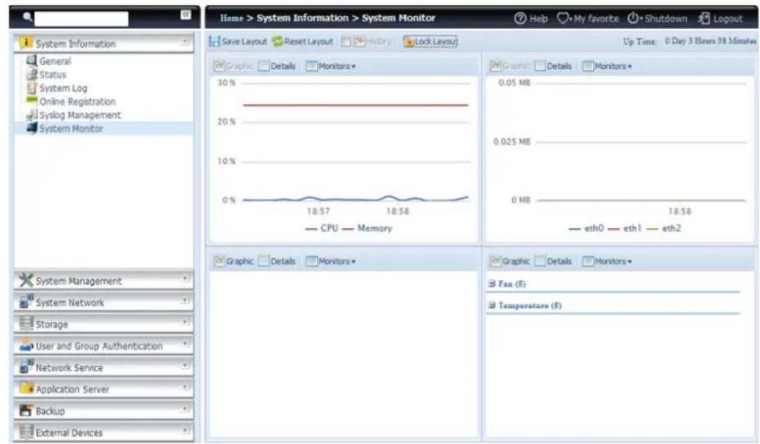
text_image
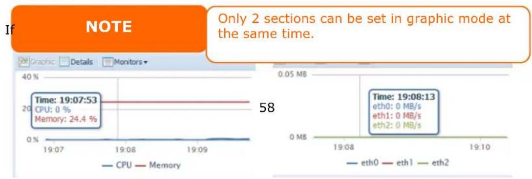
Home > System Information > System Monitor Help My favorite Shutdown Logout Save Layout Reset Layout History Lock Layout Up Time: 0 Day 3 Hours 38 Minutes System Information General Status System Log Online Registration Syslog Management System Monitor Graphic Details Monitors 30% 20% 10% 0% CPU Memory Graphic Details Monitors 0.05 MB 0.025 MB 0 MB 18:58 eth0 eth1 eth2 System Management System Network Storage User and Group Authentication Network Service Application Server Backup External Devices Graphic Details Monitors Fan ($) Temperature ($)It is divided into 4 sections. Each section can be modified to monitor specific items by using the drop down list from the "Monitors" tab, simply click on the items you would like to monitor. From each section, you can also choose to display the information graphically by selecting "Graphic" or by plain text mode by selecting "Details".
line
| Metric | Time | |--------|----------| | CPU | 0% | | Memory | 24.4% | | Time | 19:07:53 | | Time | 19:08:13 | | eth0 | 0 MB/s | | eth1 | 0 MB/s | | eth2 | 0 MB/s |resume of the information is displayed by dragging the mouse over the graphic at a specific time. See example below:
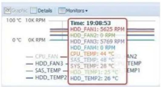
text_image
Time: 19:08:53 HDD_FAN1: S625 RPM HDD_FAN2: 0 RPM HDD_FAN3: S769 RPM HDD_FAN4: 0 RPM CPU_TEMP: 44 °C SAS_TEMP: 48 °C SYS_TEMP: 28 °C HDD_TEMP1: 25 °C HDD_TEMP2: 26 °C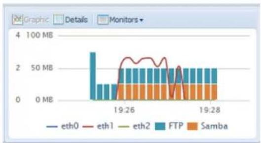
bar_stacked
| Time | eth0 (MB) | eth1 (MB) | eth2 (MB) | FTP (MB) | Samba (MB) | |---|---|---|---|---|---| | 19:26 | 0 | 25 | 0 | 10 | 10 | | 19:27 | 0 | 20 | 0 | 10 | 10 | | 19:28 | 0 | 20 | 0 | 10 | 10 |For the on-line users list, system monitor will display the on-line users and the share folder they have visited.
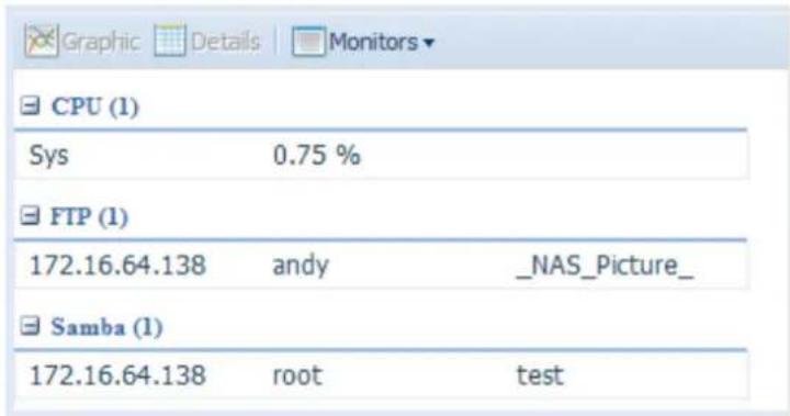
text_image
CPU (1) Sys 0.75 % FTP (1) 172.16.64.138 andy _NAS_Picture_ Samba (1) 172.16.64.138 root test| System Monitor | |
| Item | Description |
| Save Layout | Saving selected monitoring items. Layout will remain the same for future visits. |
| Reset Layout | Set back to default monitoring settings and layout. |
| History | Click on this check box and system monitor will write the monitoring history to a designate path in the RAID volume. |
| Lock Layout | All of the monitoring items are fixed and cannot be changed. Click again to unlock it. |
If the History has been enabled, click on and system monitor will display the history with different period for selection.
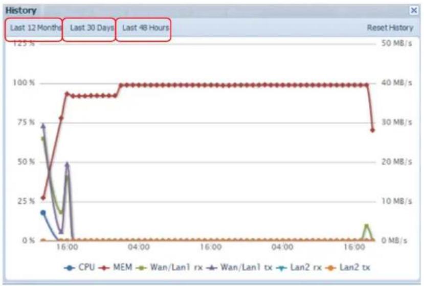
line
| Time | CPU | MEM | Wan/Lan1 rx | Wan/Lan1 tx | Lan2 rx | Lan2 tx | | ---------- | ----- | ----- | ----------- | ----------- | ------- | ------- | | 0 | 20% | 25% | 75% | 75% | 0% | 0% | | 16:00 | 0% | 95% | 50% | 50% | 0% | 0% | | 04:00 | 0% | 100% | 0% | 0% | 0% | 0% | | 16:00 | 0% | 100% | 0% | 0% | 0% | 0% |Hardware Information
From the System Information category, choose the Hardware Information item and the system will display the related HW details for the associated model. Below is an example of the information for a Thecus N4800Eco.
text_image
System Information General Status System Log Syslog Management System Monitor Hardware Information User Access Log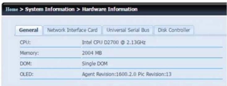
text_image
Home > System Information > Hardware Information General Network Interface Card Universal Serial Bus Disk Controller CPU: Intel CPU D2700 @ 2.13GHz Memory: 2004 MB DOM: Single DOM OLED: Agent Revision:1600.2.0 Plc Revision:13User Access Log
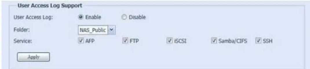
text_image
User Access Log Support User Access Log: Enable Disable Folder: NAS_Public Service: AFP FTP iSCSI Samba/CIFS SSH Apply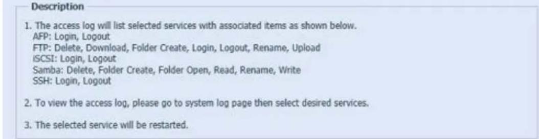
text_image
Description 1. The access log will list selected services with associated items as shown below. AFP: Login, Logout FTP: Delete, Download, Folder Create, Login, Logout, Rename, Upload iSCSI: Login, Logout Samba: Delete, Folder Create, Folder Open, Read, Rename, Write SSH: Login, Logout 2. To view the access log, please go to system log page then select desired services. 3. The selected service will be restarted.The User Access Log Support section allows administrators to select the desired protocols to record user activity for.
| User Access Log | |
| Item | Description |
| User access log | Enable or disable the User Access Log service. |
| Folder | Select from the dropdown list where to store the user access log. |
| Service | Select from the check box which access details to record. |
| Apply | Click Apply to save changes. |
| Description | The user access list will record different activities depending on which protocol is selected.1. AFP: User login and logout.2. FTP: User file deletion, uploads/downloads, folder creation, object renaming, and login and logout.3. iSCSI (if applicable): User login and logout.4. Samba: User file deletion, folder creation, folder opening, and object reading, renaming, and writing.5. SSH (if applicable): User login and logout. |
After the User Access Log Support has been set up and the "Apply" button selected, all selected services will restart.
To view user access details related to the selected service(s), please go to System Log and choose a service from the "Display" dropdown list.
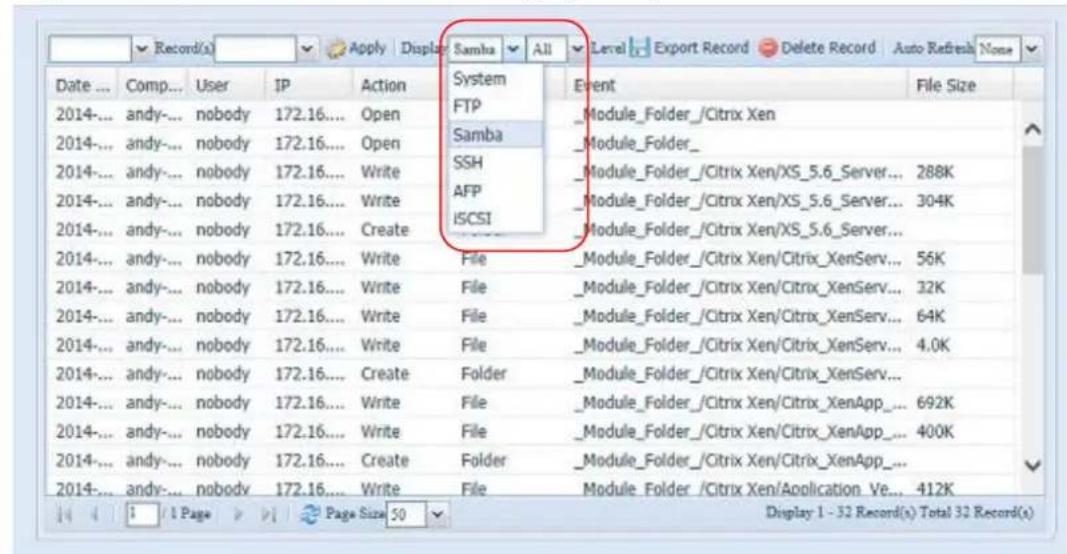
text_image
Date ... Comp... User IP Action System Event File Size 2014-... andy-... nobody 172.16.... Open FTP Samba Module_Folder_/Citrix Xen 2014-... andy-... nobody 172.16.... Open SSH Module_Folder_ 2014-... andy-... nobody 172.16.... Write SSH Module_Folder_/Citrix Xen/XS_5.6_Server... 288K 2014-... andy-... nobody 172.16.... Write AFP Module_Folder_/Citrix Xen/XS_5.6_Server... 304K 2014-... andy-... nobody 172.16.... Create ISCSI Module_Folder_/Citrix Xen/XS_5.6_Server... 2014-... andy-... nobody 172.16.... Write File Module_Folder_/Citrix Xen/Citrix_XenServ... 56K 2014-... andy-... nobody 172.16.... Write File Module_Folder_/Citrix Xen/Citrix_XenServ... 32K 2014-... andy-... nobody 172.16.... Write File Module_Folder_/Citrix Xen/Citrix_XenServ... 64K 2014-... andy-... nobody 172.16.... Write File Module_Folder_/Citrix Xen/Citrix_XenServ... 4.0K 2014-... andy-... nobody 172.16.... Create Folder Module_Folder_/Citrix Xen/Citrix_XenServ... 2014-... andy-... nobody 172.16.... Write File Module_Folder_/Citrix Xen/Citrix_XenApp... 692K 2014-... andy-... nobody 172.16.... Write File Module_Folder_/Citrix Xen/Citrix_XenApp... 400K 2014-... andy-... nobody 172.16.... Create Folder Module_Folder_/Citrix Xen/Citrix_XenApp... 2014-... andy-... nobody 172.16.... Write File Module Folder_/Citrix Xen/Application Ve... 412K Display 1 - 32 Record(s) Total 32 Record(s)To export details from the User Access Log as a single file from target folder, administrators must first select the desired number of records from the dropdown list and also select the "Auto export" option. Please choose the number of logs export and click "Apply" to activate these settings.
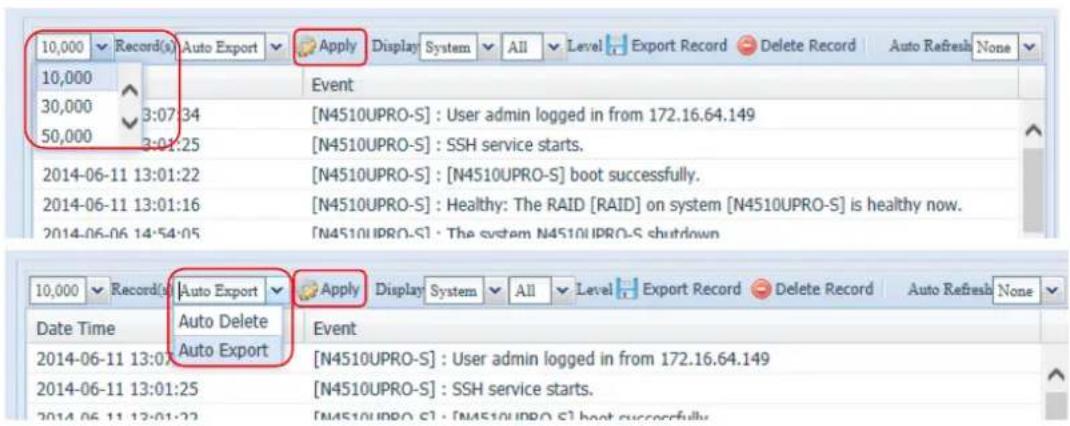
text_image
10,000 Record(s) Auto Export Apply Display System All Level Export Record Delete Record Auto Refresh None 10,000 Event 30,000 3:07:34 [N4510UPRO-S] : User admin logged in from 172.16.64.149 50,000 3:01:25 [N4510UPRO-S] : SSH service starts. 2014-06-11 13:01:22 [N4510UPRO-S] : [N4510UPRO-S] boot successfully. 2014-06-11 13:01:16 [N4510UPRO-S] : Healthy: The RAID [RAID] on system [N4510UPRO-S] is healthy now. 2014-06-06 14:54:05 [N4510UPRO-S] : The system N4510UPRO-S shutdown 10,000 Record(s) Auto Export Apply Display System All Level Export Record Delete Record Auto Refresh None Date Time Auto Delete Event 2014-06-11 13:07:34 Auto Export [N4510UPRO-S] : User admin logged in from 172.16.64.149 2014-06-11 13:01:25 [N4510UPRO-S] : SSH service starts. 2014-06-11 13:01:22 [N4510UPRO-S] : [N4510UPRO-S] boot successfully.Once (for example) 10,000 records have been reached, the log file will appear in /NAS_public/access_log/

text_image
access_log dom_repair_log dom_backup_log syslog log_20140611_161212System Management
The System Management menu gives you a wealth of settings that you can use to configure your Thecus IP storage system administration and functions. You can set up system time, system notifications, and even upgrade firmware from this menu.
Date and Time: Setting system time
From the System Management menu, choose the Date and Time item and the System Date and Time Settings screen appears. Set the desired Date, Time, and Time Zone. You can also elect to synchronize the system time on Thecus IP storage with an NTP (Network Time Protocol) Server.
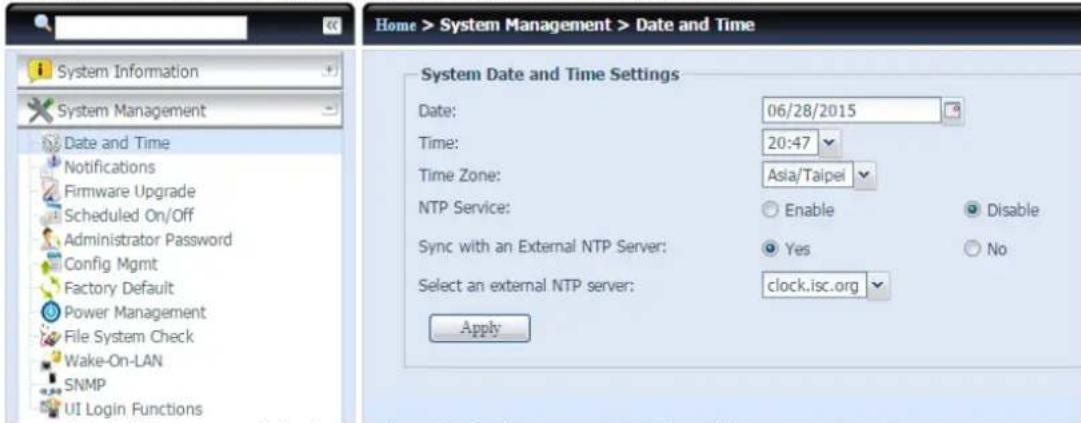
text_image
Home > System Management > Date and Time System Date and Time Settings Date: 06/28/2015 Time: 20:47 Time Zone: Asia/Taipei NTP Service: Enable Disable Sync with an External NTP Server: Yes No Select an external NTP server: clock.isc.org ApplySee the following table for a detailed description of each item:
| Time | |
| Item | Description |
| Date | Sets the system date. |
| Time | Sets the system time. |
| Time Zone | Sets the system time zone. |
| NTP Service | Select Enable to synchronize with the NTP server.Select Disable to close the NTP server synchronization. |
| Sync with external NTP Server | Select YES to allow Thecus IP storage to synchronize with an NTP server of your choice. |
| Select an external NTP server | Choice an external NTP server. |
| Apply | Click Apply to save changes. |
WARNING
If an NTP server is selected, please make sure your Thecus IP storage has been setup to access the NTP server.
Notification configuration
From the System Management menu, choose the Notifications item, and the Notifications Configuration screen appears. This screen lets you have Thecus IP storage notify you in case of any system malfunction. Press Apply to confirm all settings. See following table for a detailed description of each item.
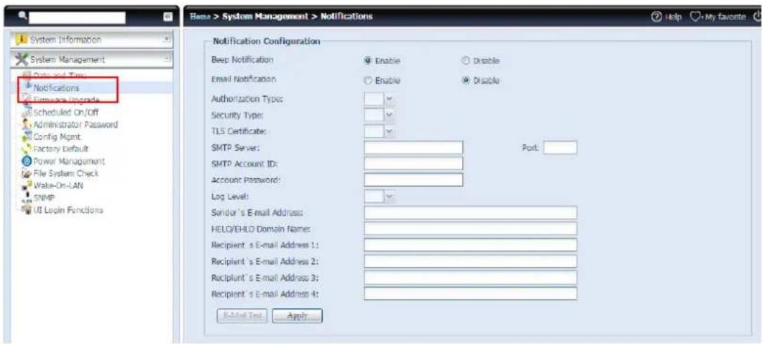
text_image
System Information System Management Data and Time Notifications Emotions Upgrade Scheduled On/Off Administrator Password Config Mgmt Factory Default Power Management File System Check Wake-On-LAN SNMP UI Login Functions Name > System Management > Notifications Help My favorite Notification Configuration Bool Notification Enable Disable Email Notification Enable Disable Authorization Type: Security Type: TLS Certificate: SMTP Server: SMTP Account ID: Account Password: Log Level: Sender's E-mail Address: HELO/EHLD Domain Name: Recipient's E-mail Address 1: Recipient's E-mail Address 2: Recipient's E-mail Address 3: Recipient's E-mail Address 4: E-mail Text Apply| Notification Configuration | |
| Item | Description |
| Beep Notification | Enable or disable the system buzzer that beeps when a problem occurs. |
| Email Notification | Enable or disable email notifications of system problems. |
| Authentication Type | Select the SMTP Server account authentication type. |
| Security Type | Select Security Type: SSL or StartTLS |
| TLS Certificate | On/off TLS Certificate. |
| SMTP Server | Specifies the hostname/IP address of the SMTP server. |
| Port | Specifies the port to send outgoing notification emails. |
| SMTP Account ID | Set the SMTP Server Email account ID. |
| Account Password | Enter a new password. |
| Log Level | Select the log level to send the e-mail out. |
| Sender's E-mail Address | Set senders email address to send email notifications. |
| HELO/EHLO Domain Name | Enter the HELO/EHLO domain name. |
| Receiver's E-mail Address (1,2,3,4) | Add one or more recipient's email addresses to receive email notifications. |
NOTE
Consult with your mail server administrator for email server information.
Firmware Upgrade
From the menu, choose the Firmware Upgrade item and the Firmware Upgrade screen appears.
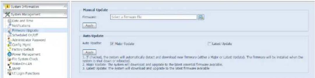
text_image
System Information System Management Date and Time Notifications Firmware Upgrade Scheduled On/Off Administrator Password Config Mgmt Factory Default Power Management File System Check Wake-On-LAN SNMP UT Login Functions Manual Update Firmware: Select a Firmware file Apply Auto Update Auto Updater | 2) Major Update □ Latest Updates Apply 1. If checked, the system will automatically detect and download new firmware (either a Major or Latest Update). The firmware will be installed when the system is shut down or rebooted. 2. Major Update: The system will download and upgrade to the latest essential firmware available. 3. Latest Update: The system will download and upgrade to the latest firmware available- Manual Update
Follow the steps below to upgrade your firmware manually:
- Use the Browse button
to find the firmware file. - Press Apply.
- The buzzer will beep and the Busy LED will blink until the upgrade is complete.

NOTE
- The buzzer only beeps if it is enabled in the System Notification menu.
- Check Thecus website for the latest firmware release and release notes.
• Downgrading firmware is not permitted.
WARNING
Do not turn off the system during the firmware upgrade process. This will lead to a catastrophic result that may render the system inoperable.
- Auto Update
If checked, the system will automatically detect and download new firmware
(either a Major or Latest Update). The firmware will be installed when the system is shut down or rebooted.
Follow the steps below to upgrade your firmware automatically:
- Check the Major Update or the Latest Update.
- Press Apply.
| Firmware Upgrade-Auto Update | |
| Item | Description |
| Major Update | The system will download and upgrade to the latest essential firmware available. |
| Latest Update | The system will download and upgrade to the latest firmware available |
Schedule Power On/Off
Using the Thecus IP storage System Management, you can save energy and money by scheduling the Thecus IP storage to turn itself on and off during certain times of the day.
From the System Management menu, choose the Schedule Power On/Off item and the Schedule Power On/Off screen appears.
To designate a schedule for the Thecus IP storage to turn on and off, first enable the feature by checking the Enable Schedule Power On/Off checkbox.
Then, simply choose an on and off time for each day of the week.
Finally, click Apply to save your changes.
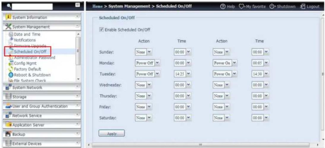
text_image
Home > System Management > Scheduled On/Off System Information System Management Date and Time Notifications Remove Upgrades Scheduled On/Off Administrator Password Config Mgmt Factory Default Reboot & Shutdown File System Check System Network Storage User and Group Authentication Network Service Application Server Backup External Devices Apply Scheduled On/Off Enable Scheduled On/Off Action Time Action Time Sunday: None 00:00 None 00:00 Monday: Power Off 00:00 Power On 00:05 Tuesday: Power Off 14:25 Power On 14:30 Wednesday: None 00:00 None 00:00 Thursday: None 00:00 None 00:00 Friday: None 00:00 None 00:00 Saturday: None 00:00 None 00:00 ApplyExample - Monday: On: 8:00; Off: 16:00
System will turn on at 8:00 AM on Monday, and off at 16:00 on Monday. System will turn on for the rest of the week.
If you choose an on time, but do not assign an off time, the system will turn on and remain on until a scheduled off time is reached, or if the unit is shutdown manually.
Example - Monday: On: 8:00
System will turn on at 8:00 AM on Monday, and will not shut down unless powered down manually.
You may also choose two on times or two off times on a particular day, and the system will act accordingly.
Example - Monday: Off: 8:00; Off: 16:00
System will turn off at 8:00 AM on Monday. System will turn off at 16:00 PM on Monday, if it was on. If the system was already off at 16:00 PM on Monday, system will stay off.
Administrator Password
From the menu, choose the Administrator Password item and the Change Administrator Password screen appears. Enter a new password in the New Password box and confirm your new password in the Confirm Password box. Press Apply to confirm password changes.
There is also a password to enter the OLED setting that you can setup here. Enter a new password in the New Password box and confirm your new password in the Confirm Password box. Press Apply to confirm password changes.
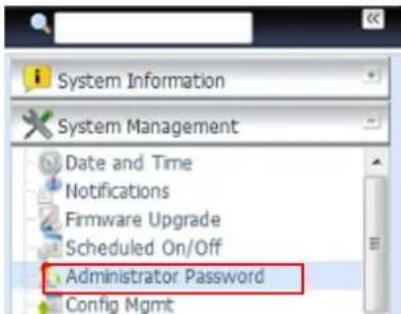
text_image
System Information System Management Date and Time Notifications Firmware Upgrade Scheduled On/Off Administrator Password Config Mgmt
text_image
Home > System Management > Administrator Change Administrator Password New Password: Confirm Password: ApplySee the following table for a detailed description of each item.
| Change Administrator and LCD Entry Password | |
| Item | Description |
| New Password | Type in a new administrator password. |
| Confirm Password | Type the new password again to confirm. |
| Apply | Press this to save your changes. |
Config Mgmt
From the menu, choose the Config Mgmt item and the System Configuration Download/Upload screen appears. From here, you can download or upload stored system configurations.
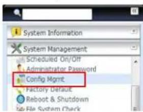
text_image
System Information System Management Scheduled On/Off Administrator Password Config Mgmt Factory Default Reboot & Shutdown Job File System Check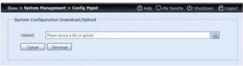
text_image
Home > System Management > Config Mgmt Help My favorite Shutdown Logout System Configuration Download/Upload Upload: Please choose a file to upload. Upload DownloadSee the following table for a detailed description of each item.
| System Configuration Download/Upload | |
| Item | Description |
| Download | Save and export the current system configuration. |
| Upload | Import a saved configuration file to overwrite the current system configuration. |
NOTE
Backing up your system configuration is a great way to ensure that you can revert to a working configuration when you are experimenting with new system settings. The system configuration you have backed up can only be restored in the same firmware version. The backup details exclude user/group accounts.
Factory Default
From the menu, choose the Factory Default item and the Reset to Factory Default screen appears. Press Apply to reset Thecus IP storage to factory default settings.
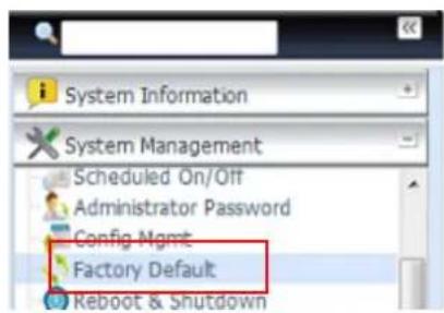
text_image
System Information System Management Scheduled On/Off Administrator Password Config Mgmt Factory Default Keboot & Shutdown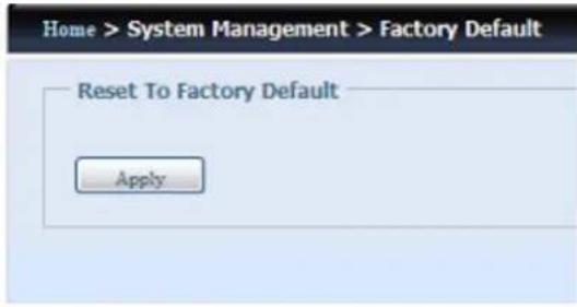
text_image
Home > System Management > Factory Default Reset To Factory Default ApplyWARNING
Resetting to factory defaults will not erase the data stored in the hard disks, but WILL revert all the settings to the factory default values.
Power Management:
From the menu, choose Power Management item, and the Shutdown/Reboot System screen appears.
- Shutdown/Reboot System
Press Reboot to restart the system or Shutdown to turn the system off.
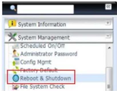
text_image
System Information System Management Scheduled On/Off Administrator Password Config Mgmt Factory Default Reboot & Shutdown File System Check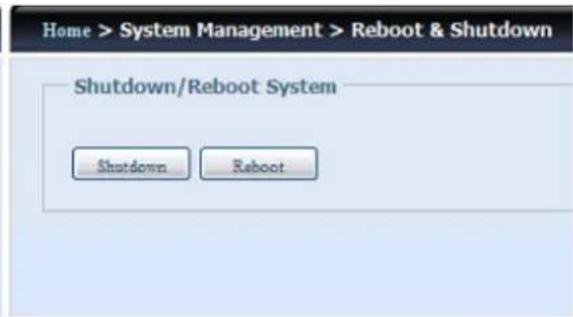
text_image
Home > System Management > Reboot & Shutdown Shutdown/Reboot System Shutdown Reboot• Automatic Resume
The setting determines how the Thecus IP Storage behaves when the power is restored after an unexpected power loss.
| Power Automatic Resume | |
| Item | Description |
| No | The Thecus IP Storage remains power off until power on manually. |
| Yes | The Thecus IP Storage power on automatically when the power restores.. |
| Previous Status | If Thecus IP Storage was on, it will power on when the power restores.If Thecus IP Storage was off, it will remains power off when the power restores. |
| Apply | Press this to save your changes. |
WARNING
The Automatic Resume feature will only be enabled when power is lost for at least 10 seconds.
File System Check
The File System Check allows you to perform a check on the integrity of your disks' file system. Under the menu, click File system Check and the File System Check prompt appears.
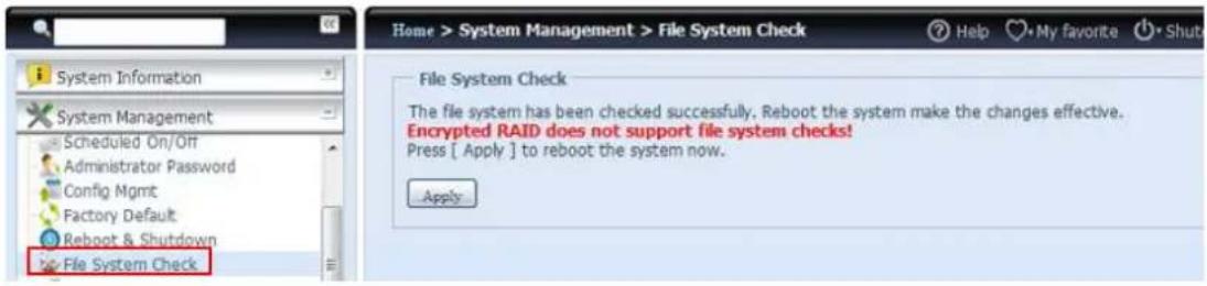
text_image
System Information System Management Scheduled On/Off Administrator Password Config Mgmt Factory Default Reboot & Shutdown File System Check Home > System Management > File System Check Help My favorite Shut File System Check The file system has been checked successfully, Reboot the system make the changes effective. Encrypted RAID does not support file system checks! Press [ Apply ] to reboot the system now. ApplyTo perform a file system check, click Apply.
Once clicked, the following prompt will appear:
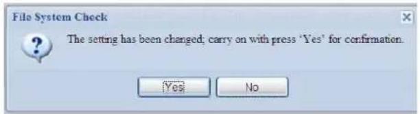
text_image
File System Check The setting has been changed; carry on with press 'Yes' for confirmation. Yes NoClick Yes to reboot the system.

flowchart
graph LR
    A["File System Check\nReboot\n64"] --> B["File System Check\nReboot\nDone."]
Once the system has rebooted, you will be returned to the File System Check prompt. There you will see the available RAID volumes to run the file system check. Check the desired RAID volumes and click Next to proceed with the file system check. Click Reboot to reboot without running the check.
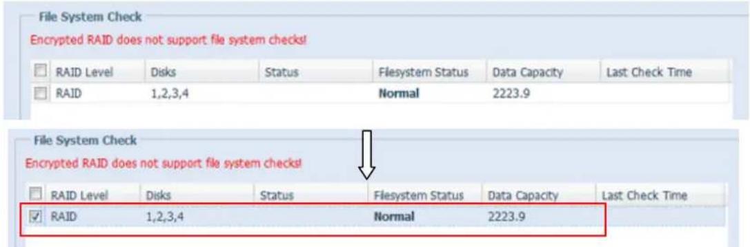
text_image
File System Check Encrypted RAID does not support file system checks! RAID Level Disks Status Flesystem Status Data Capacity Last Check Time RAID 1,2,3,4 Normal 2223.9 File System Check Encrypted RAID does not support file system checks! RAID Level Disks Status Flesystem Status Data Capacity Last Check Time RAID 1,2,3,4 Normal 2223.9Once you click Next, you will see the following screen:
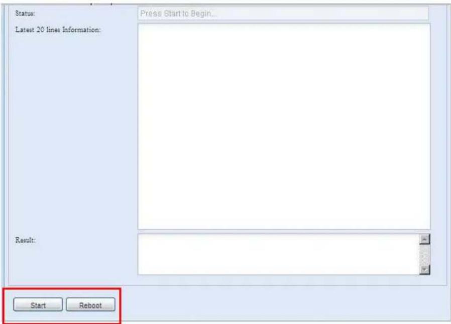
text_image
Status: Latest 20 lines Information: Press Start to Begin... Result: Start RebootClick Start to begin the file system check. Click Reboot to reboot the system. When the file system check is running, the system will show 20 lines of information until it is complete. Once complete, the results will be shown at the bottom.
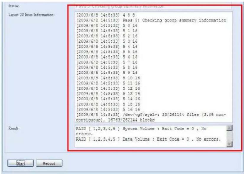
text_image
[2009/6/8 14:5:33] 4 8 8 [2009/6/8 14:5:33] Pass 5: Checking group summary information [2009/6/8 14:5:33] 5 0 16 [2009/6/8 14:5:33] 5 1 16 [2009/6/8 14:5:33] 5 2 16 [2009/6/8 14:5:33] 5 3 16 [2009/6/8 14:5:33] 5 4 16 [2009/6/8 14:5:33] 5 5 16 [2009/6/8 14:5:33] 5 6 16 [2009/6/8 14:5:33] 5 7 16 [2009/6/8 14:5:33] 5 8 16 [2009/6/8 14:5:33] 5 9 16 [2009/6/8 14:5:33] 5 10 16 [2009/6/8 14:5:33] 5 11 16 [2009/6/8 14:5:33] 5 12 16 [2009/6/8 14:5:33] 5 13 16 [2009/6/8 14:5:33] 5 14 16 [2009/6/8 14:5:33] 5 15 16 [2009/6/8 14:5:33] 5 16 16 [2009/6/8 14:5:33] /dev/vg0/syslv: 33/262144 filce (3.0% non-contiguous), 16763/262144 blocks Result: PAID [ 1,2,3,4,5 ] System Volume : Exit Code = 0 , No errors. PAID [ 1,2,3,4,5 ] Data Volume : Exit Code = 0 , No errors.NOTE
The system must be rebooted before Thecus IP storage can function normally after file system check completes.
Wake-Up On LAN (WOL)
The Thecus IP storage has the ability to be awoken from sleep mode via WAN/LAN1 or LAN2 port.
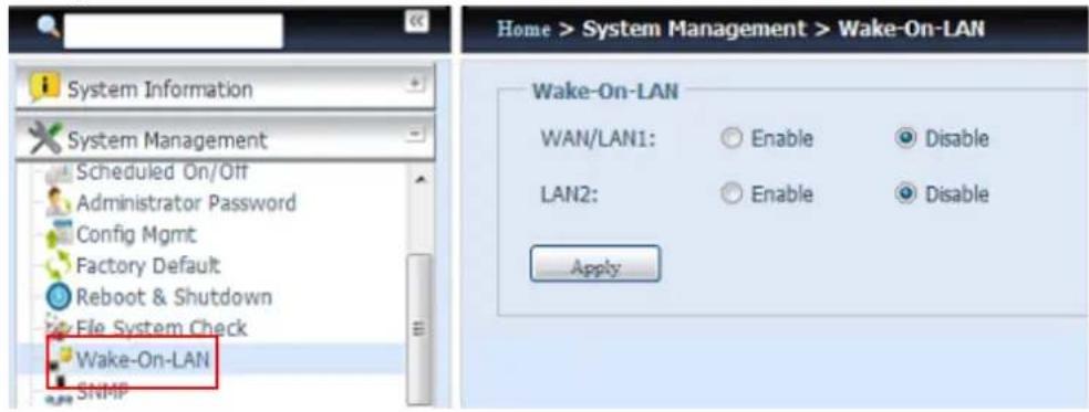
text_image
System Information System Management Scheduled On/Off Administrator Password Config Mgmt Factory Default Reboot & Shutdown File System Check Wake-On-LAN SNMP Home > System Management > Wake-On-LAN Wake-On-LAN WAN/LAN1: Enable Disable LAN2: Enable Disable ApplyFrom the menu, choose the WOL item, and the Wake-up On LAN screen appears. From here, you can Enable or Disable.
| Wake-up On LAN Configuration | |
| Item | Description |
| WAN/LAN1 | Enable or Disable WOL service from WAN/LAN1 |
| LAN2 | Enable or Disable WOL service from LAN2 |
| Apply | Click Apply to save changes. |
SNMP Support
From the menu, choose the SNMP item and the SNMP Support screen appears. You could enable the SNMP function and filled in the related information in each fields. With the SNMP management software, you can get other system's basic information.
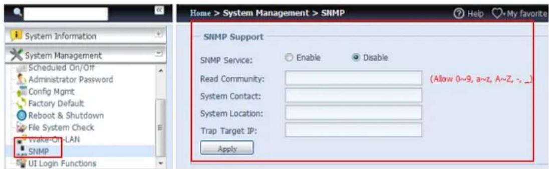
text_image
Home > System Management > SNMP SNMP Support SNMP Service: Enable Disable Read Community: (Allow 0~9, a~z, A~Z, - _) System Contact: System Location: Trap Target IP: ApplyFrom the menu, choose the SNMP item, and the SNMP Support screen appears. From here, you can Enable or Disable.
UI Login Function
Adjusts UI Login Configuration settings, you can enable/disable the Web Disk, Photo Server and modules functions, according to your needs.
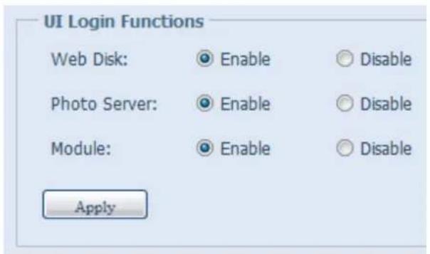
text_image
UI Login Functions Web Disk: Enable Disable Photo Server: Enable Disable Module: Enable Disable ApplySystem Network
Use the System Network menu to make network configuration settings to an on board network port or additional NIC as well as DHCP and link aggregation.
Networking
From the System Network menu, choose Networking, and the Networking Configuration screen appears. This screen displays the network parameters of the global setting and available network connection. You may change any of these items and press Apply to confirm your settings. See a description of each item in the following table:
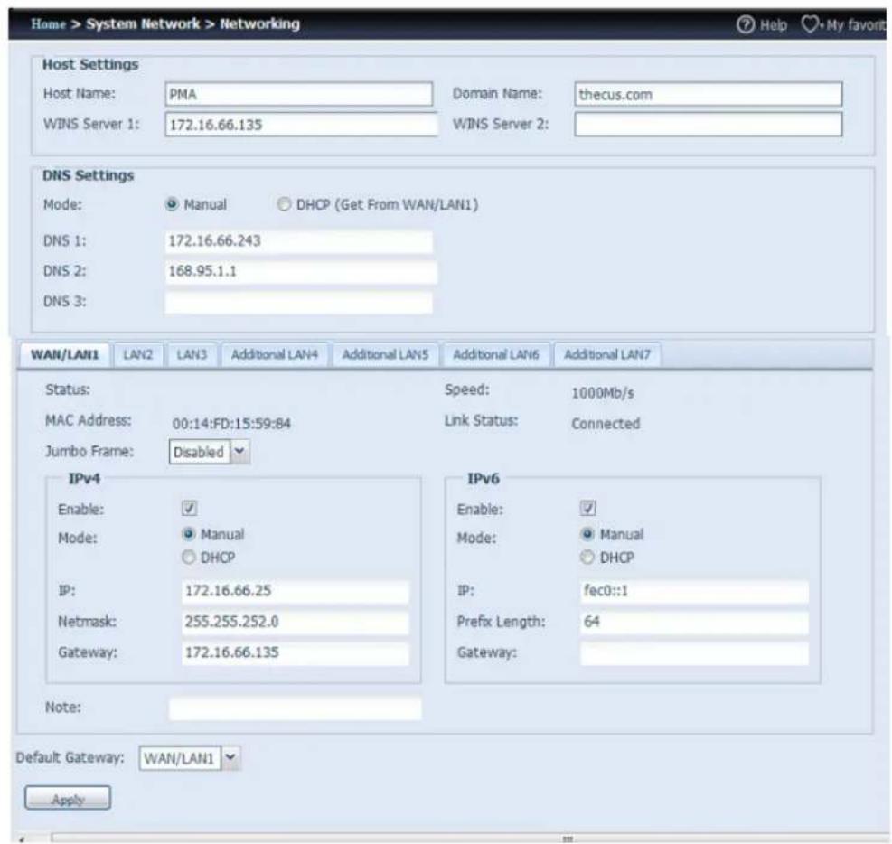
text_image
Home > System Network > Networking Host Settings Host Name: PMA Domain Name: thecus.com WINS Server 1: 172.16.66.135 WINS Server 2: DNS Settings Mode: Manual DHCP (Get From WAN/LAN1) DNS 1: 172.16.66.243 DNS 2: 168.95.1.1 DNS 3: WAN/LAN1 LAN2 LAN3 Additional LAN4 Additional LAN5 Additional LAN6 Additional LAN7 Status: Speed: 1000Mb/s MAC Address: 00:14:FD:15:59:84 Link Status: Connected Jumbo Frame: Disabled IPv4 Enable: ✓ Mode: Manual DHCP IP: 172.16.66.25 Netmask: 255.255.252.0 Gateway: 172.16.66.135 IPv6 Enable: ✓ Mode: Manual DHCP IP: fec0::1 Prefix Length: 64 Gateway: Note: Default Gateway: WAN/LAN1 ApplyThe available system network ports are coming from embedded system ports and additional system ports added through the reserved PCI-e slot with associated
compatible list. Therefore, the screen shown above is an example of a Thecus N16000 with 3 on board GbE NIC and an additionally Intel PRO/1000 PT quad port NIC, for a total of 7 NIC ports.
| Network Configuration (Global parameter) | |
| Item | Description |
| Host name | Host name that identifies the Thecus IP storage on the network. |
| Domain name | Specifies the domain name of Thecus IP storage. |
| WINS Server | To set a server name for NetBIOS computer. |
| DNS Mode | Select the DNS server is coming from DHCP server or manual input.A total of 3 DNS servers can be input. If the DNS setting is chosen from DHCP server, then it will refer to WAN/LAN1 port. |
| DNS Server 1,2,3 | Domain Name Service (DNS) server IP address. |
| Network Configuration (NIC port) | |
| Link speed | Display associated NIC port link speed. |
| Link status | Display associated NIC port link status. |
| MAC address | MAC address of the network interface. |
| Jumbo Frame Support | Enable or disable Jumbo Frame Support of associate interface on your Thecus IP storage. |
| IPv4/IPv6 | Click to enable IPv4/IPv6 for TCP/IP. The default is IPv4 enabled. |
| Mode | It can choose a static IP or Dynamic IP. |
| IP | IP address of associate NIC interface. |
| Netmask/Prefix Length | Input netmask for IPv4 and Prefix length for IPv6. |
| Gateway | Gateway for associate NIC. |
| Default gateway | It can be chosen from a drop down list of default gateway that's been used for the Thecus IP storage. |
NOTE
- Only use Jumbo Frame settings when operating in a Gigabit environment where all other clients have Jumbo Frame Setting enabled.
• Proper DNS setting is vital to networks services, such as SMTP and NTP.
WARNING
Most faster Ethernet (10/100) Switches/Routers do not support Jumbo Frame and will not be able to connect to your Thecus NAS after Jumbo Frame is turned on.
VLAN
Each NIC is capable of VLAN support. To enable VLAN, simply click the check box and input the VLAN ID (VLAN ID can be any digital number). The system with the same VLAN ID will become a Virtual LAN group to allow more specific communication among members.

text_image
WAN/LAN1 LAN2 Status: Normal Speed: 1000Mb/s MAC Address: 00:14:FD:17:99:76 Link Status: Connected Jumbo Frame: 1500 bytes Enable VLAN: VLAN ID:DHCP/RADVD
From the System Network menu, choose DHCP/RADVD, and the DHCP/RADVD Configuration screen appears. This screen displays available NIC status. If each NIC has been set-up to a static IP, then each NIC can be configured to act as DHCP/RADVD server.
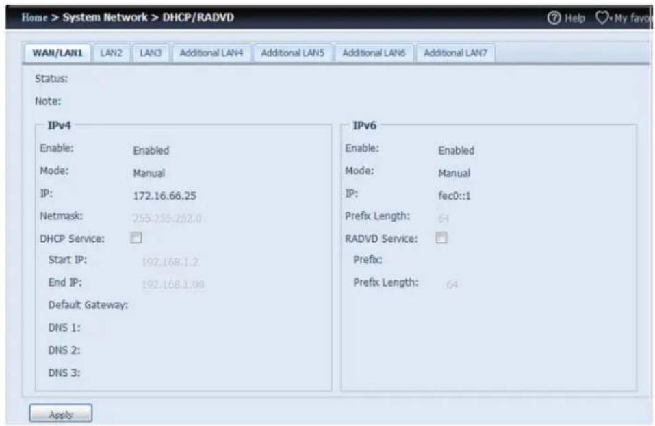
text_image
Home > System Network > DHCP/RADVD WAN/LAN1 LAN2 LAN3 Additional LAN4 Additional LAN5 Additional LAN6 Additional LAN7 Status: Note: IPv4 Enable: Enabled Mode: Manual IP: 172.16.66.25 Netmask: 255.255.252.0 DHCP Service: Start IP: 192.168.1.2 End IP: 192.168.1.09 Default Gateway: DNS 1: DNS 2: DNS 3: Apply IPv6 Enable: Enabled Mode: Manual IP: fec0::1 Prefix Length: 64 RADVD Service: Prefix: Prefix Length: 64DHCP/RADVD Server Configuration
A DHCP/RADVD server can be configured to assign IP addresses (IPv4) or Prefix (IPv6) to devices connected to the associated NIC port.
| DHCP Configuration | |
| Item | Description |
| DHCP/RADVD Service | Enable or disable the DHCP/RADVD service to automatically assign IP address to PCs connected to associate NIC interface. |
| Start IP (IPv4) | Specifies the lower IP address of the DHCP range. |
| End IP in (IPv4) | Specifies the highest IP address of the DHCP range. |
| Default Gateway (IPv4) | Specifies gateway for the DHCP server service. |
| DNS Server 1,2,3 (IPv4) | Displayed the DNS server IP address. |
| Prefix (IPv6) | Specifies prefix |
| Prefix Length (IPv6) | Specifies prefix length |
WARNING
The IP address of associated NIC should not be in the range of the Start IP address and End IP address (IPv4).
Linking Aggregation
The Thecus IP storage supports link aggregation from either on board network port or additional NIC. Simply click on "+" as shown in the screen shot below.
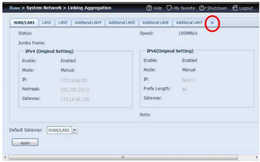
text_image
Home > System Network > Linking Aggregation WAN/LAN1 LAN2 LAN3 Additional LAN4 Additional LAN5 Additional LAN6 Additional LAN7 Status: Speed: 1000Mb/s Jumbo Frame: IPv4 (Original Setting) Enable: Enabled Mode: Manual IP: 172.16.66.25 Netmask: 255.255.252.0 Gateway: 172.16.66.135 IPv6(Original Setting) Enable: Enabled Mode: Manual IP: fec0::1 Prefix Length: 64 Gateway: Note: Default Gateway: WAN/LAN1 ApplyThe associated screen shot will appear after the "+" is clicked.
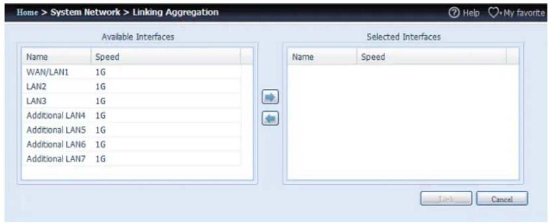
text_image
Home > System Network > Linking Aggregation Available Interfaces Name Speed WAN/LAN1 1G LAN2 1G LAN3 1G Additional LAN4 1G Additional LAN5 1G Additional LAN6 1G Additional LAN7 1G Selected Interfaces Name Speed Lock CancelSelect from available network port then move over to selected box.
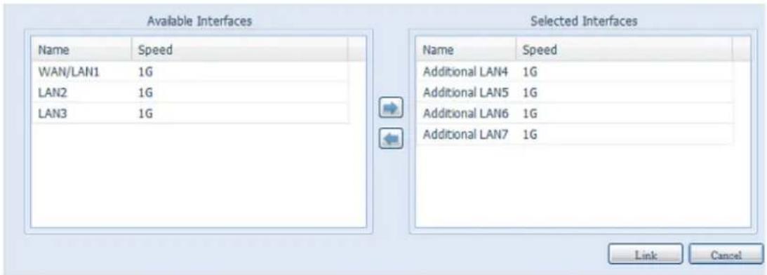
text_image
Available Interfaces Name Speed WAN/LAN1 1G LAN2 1G LAN3 1G Selected Interfaces Name Speed Additional LAN4 1G Additional LAN5 1G Additional LAN6 1G Additional LAN7 1G Link CancelClick "Link" to confirm the selection. The newly created tab will appear for more settings required to complete the link aggregation configuration.
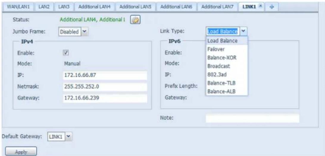
text_image
WAN/LAN1 LAN2 LAN3 Additional LAN4 Additional LAN5 Additional LAN6 Additional LAN7 LINK1 Status: Additional LAN4, Additional I Jumbo Frame: Disabled IPv4 Enable: ✓ Mode: Manual IP: 172.16.66.87 Netmask: 255.255.252.0 Gateway: 172.16.66.239 Link Type: Load Balance IPv6 Load Balance Enable: Failover Mode: Balance-XOR IP: Broadcast Prefix Length: 802.3ad Gateway: Balance-TLB Balance-ALB Note: Default Gateway: LINK1 Apply| Link1 Configuration | |
| Status | Specifies the network ports being used with the associated link aggregation.Click on to modify the selected network ports. |
| Jumbo Frame Support | Enable or disable Jumbo Frame Support of the associated interface on your Thecus IP storage. |
| Link Type | Select from drop down list for desired mode. |
| IPv4/IPv6 | Click to enable IPv4/IPv6 for TCP/IP. The default is IPv4 enabled. |
| Mode | It has to be a static IP with the link aggregation being used. |
| IP | IP address of link aggregation. |
| Netmask/Prefix Length | Input netmask for IPv4 and Prefix length for IPv6. |
| Gateway | Gateway for associated link aggregation |
| Default gateway | It can be chosen from the drop down list of default gateway being used for the Thecus IP storage. |
Now under the networking, a "Link1" tab will appear from the network title bar.

text_image
Home > System Network > Networking Host Settings Host Name: PMA Domain Name: thecus.com WINS Server 1: WINS Server 2: DNS Settings Mode: Manual DHCP (Get From WAN/LAN1) DNS 1: DNS 2: DNS 3: LAN2 LAN3 Additional LAN4 Additional LAN5 Additional LAN6 Additional LAN7 LINK1 Status: Speed: 1000Mb/s MAC Address: 00:14:FD:15:59:84 Link Status: Connected Jumbo Frame: Disabled IPv4 IPv6To modify or delete LINK1, go to Link Aggregation setting page. Click on
to modify the settings or click on

ports are still available, additional link aggregation links can be created by clicking

Additional LAN
Other than on-board LAN port, Thecus IP storage supports additional NIC to be added in its available PCI-e slot. For the details of additional NIC support list please visit Thecus website.
http://www.thecus.com/sp_comlist.php
Once the additional NIC is installed into Thecus IP storage, the "Additional LANx" will appear under the "Networking" category. Click the associated NIC to setup the details. The screen shot below shows an example of an Intel PRO/1000 PT Quad port installed thru a PCI-e slot in the Thecus IP storage.
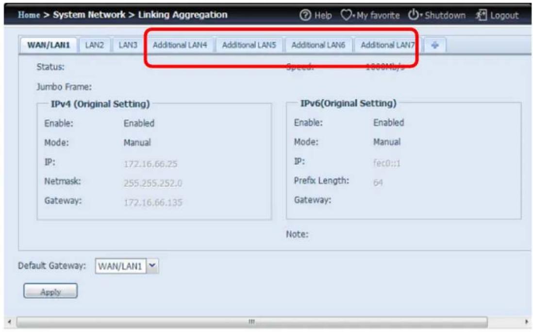
text_image
Home > System Network > Linking Aggregation WAN/LAN1 LAN2 LAN3 Additional LAN4 Additional LAN5 Additional LAN6 Additional LAN7 Status: Speed: 1000Mbps Jumbo Frame: IPv4 (Original Setting) Enable: Enabled Mode: Manual IP: 172.16.66.25 Netmask: 255.255.252.0 Gateway: 172.16.66.135 IPv6(Original Setting) Enable: Enabled Mode: Manual IP: fec0::1 Prefix Length: 64 Gateway: Note: Default Gateway: WAN/LAN1 ApplyStorage Management
The Storage menu displays the status of storage devices installed in the Thecus IP storage. It includes storage configuration options such as RAID and disk settings, folder configuration, iSCSI and ISO Mount.
Disk Information
From the Storage menu, choose the Disk Information item and the Disk Information screen appears. From here, you can see various installed hard disks. The disk slot position will appear if the mouse is moved over the installed disk.
NOTE
- The screen shot below is just an example from a Thecus IP Storage. The disk slots number can range from 8, 12 to 16 slots depending on the model of Thecus IP storage. Also it will list the disk info of JBOD devices if applicable
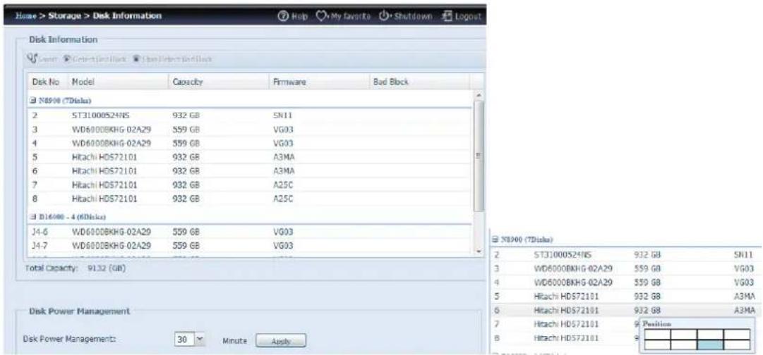
text_image
Home > Storage > Disk Information Disk Information Sapien Select Back Back Select Back Back Disk No Model Capacity Firmware Bad Block N8900 (TDisk) 2 ST31000524NS 932 GB SN11 3 WD6000BKHG-02A29 559 GB VG03 4 WD6000BKHG-02A29 559 GB VG03 5 Hitachi HD572101 932 GB A3MA 6 Hitachi HD572101 932 GB A3MA 7 Hitachi HD572101 932 GB A25C 8 Hitachi HD572101 932 GB A25C D16000 - 4 (DDisk) J4-6 WD6000BKHG-02A29 559 GB VG03 J4-7 WD6000BKHG-02A29 559 GB VG03 Total Capacity: 9132 (GB) Disk Power Management Disk Power Managements: 30 Minute Apply N8900 (TDisk) 2 ST31000524NS 932 GB SN11 3 WD6000BKHG-02A29 559 GB VG03 4 WD6000BKHG-02A29 559 GB VG03 5 Hitachi HD572101 932 GB A3MA 6 Hitashi HD572101 932 GB A3MA 7 Hitachi HD572101 Position 8 Hitachi HD572101| Disks Information | |
| Item | Description |
| Disk No. | Indicates disk location. |
| Capacity | Shows the SATA hard disk capacity. |
| Model | Displays the SATA hard disk model name. |
| Firmware | Shows the SATA hard disk firmware version. |
| Bad Block scan | Yes to start scan Bad Block. |
S.M.A.R.T. Information
On the Disk Information screen, select a disk then click on "Smart" to list the S.M.A.R.T. info of the associated disk.
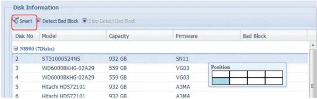
text_image
Disk Information Smart Detect Bad Block Stop Detect Bad Block Disk No Model Capacity Firmware Bad Block N8900 (7Disk) 2 ST31000524NS 932 GB SN11 3 WD6000BKHG-02A29 559 GB VG03 4 WD6000BKHG-02A29 559 GB VG03 5 Hitachi HDS72101 932 GB A3MA 6 Hitachi HDS72101 932 GB A3MA PositionYou may also perform a disk SMART test (doesn't apply to SAS HDD); simply click "Test" to start the SMART test. The result is only for reference and the system will not take any action from its results.
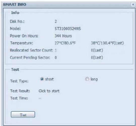
text_image
SMART INFO Info Disk No.: 2 Model: ST31000524NS Power On Hours: 344 Hours Temperature: 27°C/80.6°F 38°C/100.4°F(Last) Reallocated Sector Count: 1 0(Last) Current Pending Sector: 0 0(Last) Test Test Type: short long Test Result: Click to start Test Time: - Test| S.M.A.R.T. Information | |
| Item | Description |
| Tray Number | Tray the hard disk is installed in. |
| Model | Model name of the installed hard disk. |
| Power ON Hours | Count of hours in power-on state. The raw value of this attribute shows total count of hours (or minutes, or seconds, depending or manufacturer) in power-on state. |
| Temperature Celsius | The current temperature of the hard disk in degrees Celsius. |
| Reallocated Sector Count | Count of reallocated sectors. When the hard drive finds a read/write/verification error, it marks this sector as "reallocated" and transfers data to a special reserved area (spare area). This process is also known as remapping and "reallocated" sectors are called remaps. This is why, on a modern hard disks, you cannot see "bad blocks" while testing the surface - all bad blocks are hidden in reallocated sectors. However, the more sectors that are reallocated, the more a decrease (up to 10% or more) can be noticed in disk read/write speeds. |
| Current Pending Sector | Current count of unstable sectors (waiting for remapping). The raw value of this attribute indicates the total number of sectors waiting for remapping. Later, when some of these sectors are read successfully, the value is decreased. If errors still occur when reading sectors, the hard drive will try to restore the data, transfer it to the reserved disk area (spare area), and mark this sector as remapped. If this attribute value remains at zero, it indicates that the quality of the corresponding surface area is low |
| Test Type | Set short or long time to test. |
| Test Result | Result of the test. |
| Test Time | Total time of the test. |
NOTE
If the Reallocated Sector Count > 32 or the Current Pending Sector of a hard disk drive > 0, the status of the disk will show "Warning". This warning is only used to alert the system administrator that there are bad sectors on the disk, and they should replace those disks as soon as possible.
Bad Block Scan
On the Disk Information screen, select a disk then click on "Detect Bad Block" to perform bad block scan of the associated disk. The result is only for reference and the system will not take any action from its results.
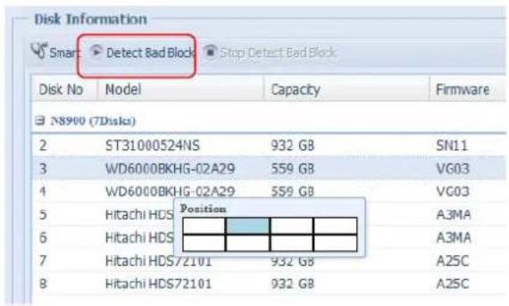
text_image
Disk Information Smart: Detect Bad Block Stop Detect Bad Block Disk No Model Capacity Firmware N8900 (7Disks) 2 ST31000524NS 932 GB SN11 3 WD6000BKHG-02A29 559 GB VG03 4 WD6000BKHG-02A29 559 GB VG03 5 Hitachi HDS Position A3MA 6 Hitachi HDS A3MA 7 Hitachi HDS72101 932 GB A25C 8 Hitachi HDS72101 932 GB A25CThe bad block scan can be terminated by clicking on "Stop Detect Bad Block".
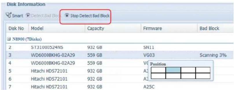
text_image
Disk Information Smart Detect Bad Block Stop Detect Bad Block Disk No Model Capacity Firmware Bad Block N8900 (7Disks) 2 ST31000524NS 932 GB SN11 3 WD6000BKHG-02A29 559 GB VG03 Scanning 3% 4 WD6000BKHG-02A29 559 GB V0 Position 5 Hitachi HDS72101 932 GB A3 6 Hitachi HDS72101 932 GB A2 7 Hitachi HDS72101 932 GB A25CFor Thecus product (N8900/N12000/N16000 series) which support JBOD device, the attached JBOD device and his associated disks will also list under the Disk Information page. Please see below for a screen shot of a N8900 with a Thecus D16000 attached and installed disks list on.
The JBOD device will have a unique ID that ranges from 1 to 10. The disk no. lead ID will indicate the different JBOD devices. The screen shot below show a JBOD device with ID 4, so J4-6 is indicated under the JBOD device disk list with 6 slots.
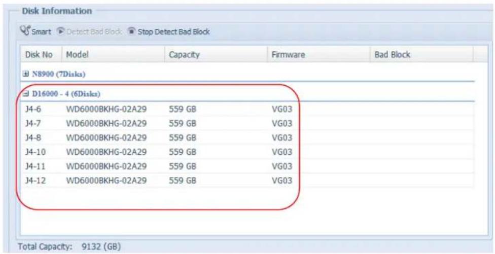
text_image
Disk Information Smart Detect Bad Block Stop Detect Bad Block Disk No Model Capacity Firmware Bad Block N8900 (7Disks) D16000 - 4 (6Disks) J4-6 WD6000BKHG-02A29 559 GB VG03 J4-7 WD6000BKHG-02A29 559 GB VG03 J4-8 WD6000BKHG-02A29 559 GB VG03 J4-10 WD6000BKHG-02A29 559 GB VG03 J4-11 WD6000BKHG-02A29 559 GB VG03 J4-12 WD6000BKHG-02A29 559 GB VG03 Total Capacity: 9132 (GB)RAID Information
From the Storage menu, choose the RAID Management item and the RAID Management screen appears.
This screen lists the RAID volumes currently residing in the Thecus IP storage. From this screen, you can get information about the status of your RAID volumes, as well as the capacities allocated for data.
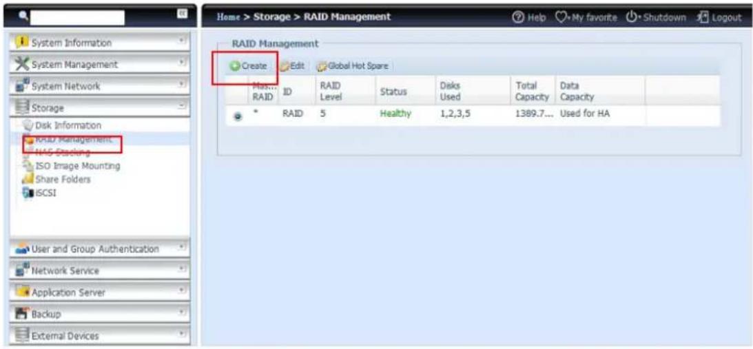
text_image
Home > Storage > RAID Management RAID Management Create Edit Global Hot Spare Maximum RAID ID RAID Level Status Disks Used Total Capacity Data Capacity * RAID 5 Healthy 1,2,3,5 1389.7... Used for HA System Information System Management System Network Storage Disk Information RAID Management NAG Stacking ISO Image Mounting Share Folders ISCSI User and Group Authentication Network Service Application Server Backup External Devices| RAID Information | |
| Item | Description |
| Master RAID | The RAID volume currently designated as the Master RAID volume. |
| ID | ID of the current RAID volume.NOTE: All RAID IDs must be unique. |
| RAID Level | Shows the current RAID configuration. |
| Status | Indicates status of the RAID. Can read either Healthy, Degraded, or Damaged. |
| Disks Used | Hard disks used to form the current RAID volume. |
| Total Capacity | Total capacity of the current RAID. |
| Data Capacity | Indicates the used capacity and total capacity used by user data. |
Create a RAID
On the RAID Information screen, press the Create button to go to the RAID Volume Creation screen. In addition to RAID disk information and status, this screen lets you make RAID configuration settings.
Using Create RAID, you can select stripe size, choose which disks are RAID disks or the Spare Disk. .
| RAID Configurations | |
| Item | Description |
| Disk No. | Number assigned to the installed hard disks. |
| Capacity (MB) | Capacity of the installed hard disks. |
| Model | Model number of the installed hard disks. |
| Status | Status of the installed hard disks. |
| Used | If this is checked, current hard disk is aalready part of a RAID volume. |
| Spare | If this is checked, current hard disk is designated as a spare for a RAID volume. |
| Master RAID | Check a box to designate this as the Master RAID volume. See the NOTE below for more information. |
| Stripe Size | This sets the stripe size to maximize performance of sequential files in a storage volume. Keep the 64K setting unless you require a special file storage layout in the storage volume. A larger stripe size is better for large files. |
| Data Percentage | The percentage of the RAID volume that will be used to store data. |
| Create | Press this button to configure a file system and create the RAID storage volume. |
To create a RAID volume, follow the steps below:
- On the RAID Information screen, clicks create.
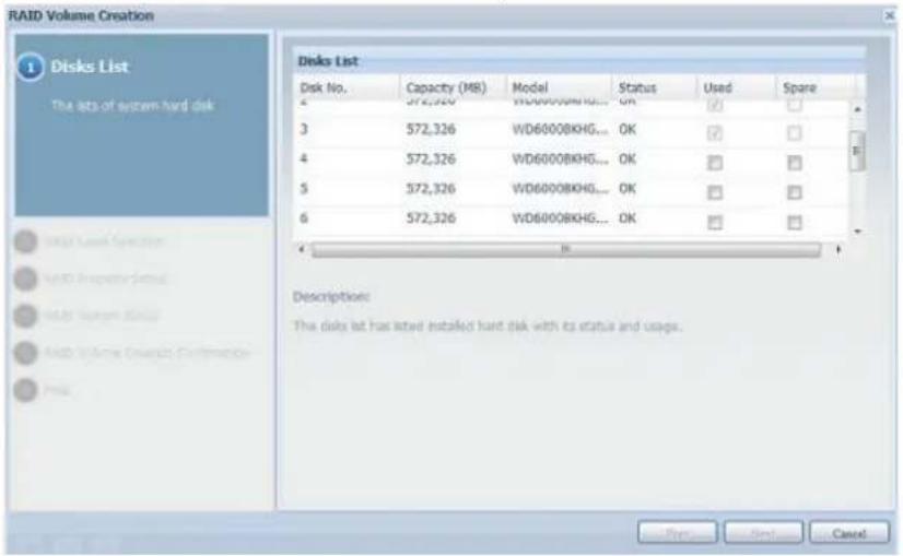
text_image
RAID Volume Creation 1 Disks List The sets of system hard disk Disk List Disk No. Capacity (MB) Model Status Used Spare 4 572,326 WD6000BKHG... OK ✓ ✓ 3 572,326 WD6000BKHG... OK ✓ ✓ 4 572,326 WD6000BKHG... OK ✓ ✓ 5 572,326 WD6000BKHG... OK ✓ ✓ 6 572,326 WD6000BKHG... OK ✓ ✓ Description: The disk let has latest installed hard disk with its status and usage. Page Sell Cancel- On the RAID Configuration screen, set the RAID storage space as JBOD, RAID 0, RAID 1, RAID 5, RAID 6, RAID 10, RAID 50 or RAID 60 (depends on model)—see Appendix B: RAID Basics for a detailed description of each.
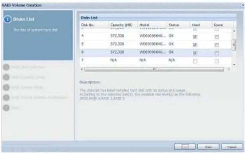
text_image
RAID Volume Creation 1 Disks List The lists of system hard disk Disk List Disk No. Capacity (MB) Model Status Used Spare 4 572,326 WD6000BKHG... OK ✓ ✓ 3 572,326 WD6000BKHG... OK ✓ ✓ 0 572,326 WD6000BKHG... OK ✓ ✓ 7 N/A N/A N/A ✓ ✓ Description: The disks list has listed installed hard disk with its status and image... According to the selected disk(s), the available red-level(s) as the following: J800.RAID RAID 1.RAID 5 Enter Next CancelNOTE
N8900/N12000/N16000 Series supports multiple RAID modes and are capable of creating up to five RAID volumes within a single NAS system.
- Specify a RAID ID.
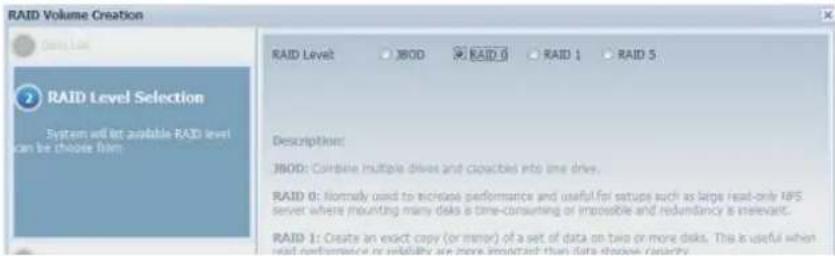
text_image
RAID Volume Creation RAID Level JBOD RAID 0 RAID 1 RAID 5 2 RAID Level Selection System will let available RAID level can be choose film. Description: JBOD: Coinbine multiple drives and capacities into time drive. RAID 0: Normally used to increase performance and useful for setups such as large real-only MPS server where mounting many disks a time-consuming or impossible and redundancy is relevant. RAID 1: Create an exact copy (or minor) of a set of data on two or more disks. This is useful when read performance or reliability are more important than data choose priority.- If this RAID volume is meant to be the Master RAID volume, tick the Master RAID checkbox.
NOTE
In a multiple RAID configuration, one RAID volume must be designated as the Master RAID volume. The Master RAID volume will store all installed modules. If the Master RAID is changed to another location (i.e. assigning volume 2 to be the Master RAID volume after volume 1 had been previously assigned), then all modules must be reinstalled. In addition, all system folders that were contained on the Master RAID volume will be invisible. Reassigning this volume to be the Master RAID will make these folders visible again.
- Selected whether the RAID volume will be encrypted or not. The RAID volume can protect data by using RAID Volume Encryption function to prevent the risk of data exposure. To activate this function, the Encryption option needs to be enabled while the RAID is created and followed by a password input for identification. Also, an external writable USB disk plugged into any USB port on the system is required to save the password you have entered while the RAID volume is being created. See the screenshot below for details.
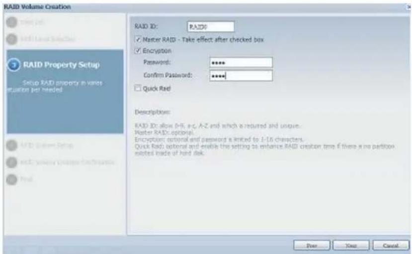
text_image
RAID Volume Creation RAID ID: RAID ✓ Master RAID - Take effect after checked box ✓ Encryption Password: ****** Confirm Password: ****** □ Quick Rad Descriptions: RAID ID: allow D=5, a=c, A-Z and which is required and unique. Master RAID: optional. Encryption: optional and password is limited to 1-16 characters. Quick Rad: optional and enable this setting to enhance RAID creation time if there is no partition elements made of hard disk. Power Next CancelOnce the Create button has been pressed with the Encryption checkbox enabled, the following message pop-up will appear for confirmation.
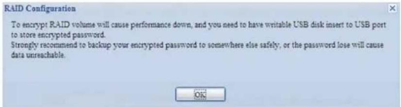
text_image
RAID Configuration To encrypt RAID volume will cause performance down, and you need to have writable USB disk insert to USB port to store encrypted password. Strongly recommend to backup your encrypted password to somewhere else safely, or the password lose will cause data unreachable.After the RAID volume has been created, you may remove the USB disk until the next time the system boots. The RAID volume cannot be mounted if the USB disk with the encryption key isn't found in any system USB port when the volume is accessed. To activate the encrypted volume, plug the USB disk containing the encryption key and into any system USB port.
We strongly recommended copying the RAID volume encryption key to a safe place. You can find the encryption key file from the USB disk in the following format:
(RAID volume created date)_xxxxx.key
WARNING
Please keep your USB disk in a safe place and also backup the encrypted key.
There is no way to rescue data back if the key is lost.
NOTE
With RAID volume encryption enabled, the system performance will go down.
RAID volumes with encryption enabled will be displayed with a key lock symbol next to volume ID name.
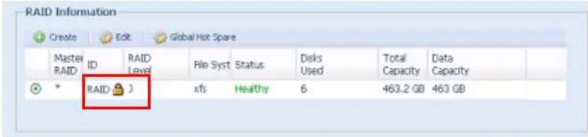
text_image
RAID Information Create Edit Global Hot Spare Master ID RAID File Syst Status Disks Total Data RAID 3 xfs Healthy 6 463.2 GB 463 GB- Quick RAID — Enabled the quick RAID setting is going to enhance RAID creation time.
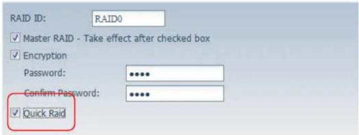
text_image
RAID ID: RAID0 ✓ Master RAID - Take effect after checked box ✓ Encryption Password: ••••• Confirm Password: ••••• ✓ Quick RaidNOTE
We recommend using the "Quick RAID" setting only if the hard disks are brand new or if no existing partitions are contained.
-
Specify a stripe size — 64K is the default setting.
-
Selected the file system you would like to have for this RAID volume. The selection is available from ext3, XFS and ext4.
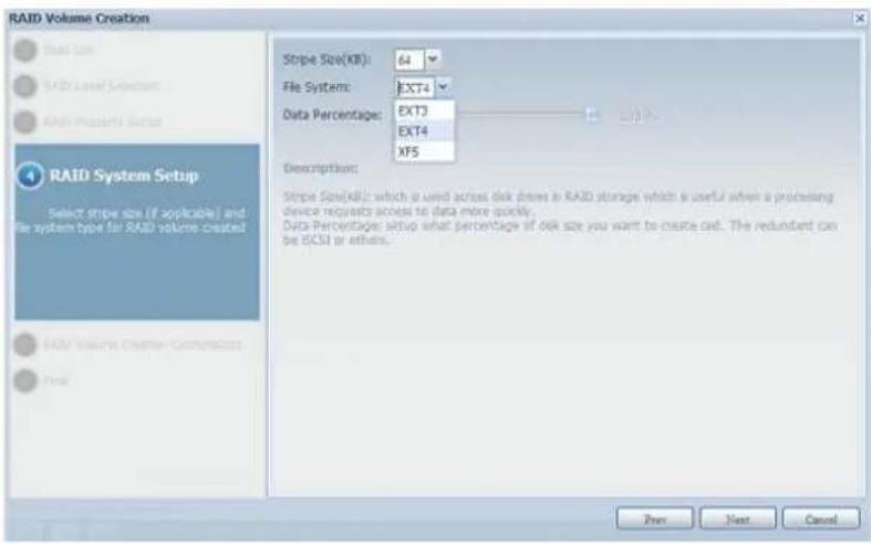
text_image
RAID Volume Creation Stripe Size(KX): 64 File System: EXT4 Data Percentage: EXT3 EXT4 XFS Description: Stripe Size(KX): which is used across disk drives in RAID storage which is useful when a processing device requests access to data more quickly. Data Percentages: setup what percentage of disk size you want to create call. The redundant can be iOSI or others. Select stripe size (if applicable) and file system type for RAID volume created RAID Volume Creation: Crammation Free Prev Next CancelNOTE
Single volume size supported:
ext3 → 8TB
XFS → 48TB
ext4 → 36TB
- Press Submit to build the RAID storage volume.
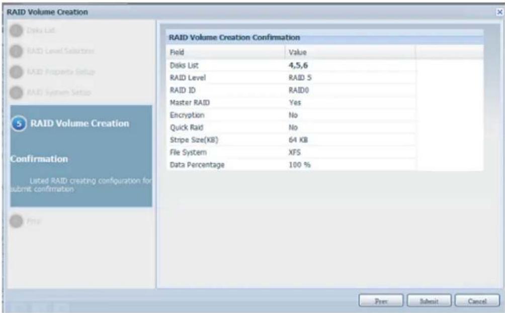
text_image
RAID Volume Creation File List RAID Level Selection RAID Property Setup RAID System Setup RAID Volume Creation Confirmation Listed RAID creating configuration for submit confirmation Data Percentage 100 % RAID Volume Creation Confirmation Field Value Disks List 4,5,6 RAID Level RAID 5 RAID ID RAID0 Master RAID Yes Encryption No Quick Raid No Stripe Size(KB) 64 KB File System XFS Pree Submit Cancel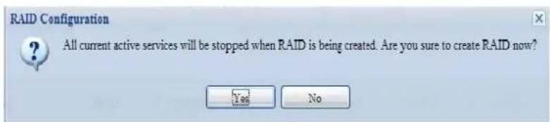
text_image
RAID Configuration All current active services will be stopped when RAID is being created. Are you sure to create RAID now? Yes No- Press "Yes" for RAID volume creation preparation. Then click "Finish" to start up with RAID volume building.
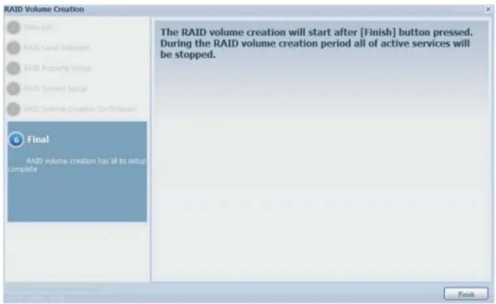
text_image
RAID Volume Creation Take List RAID Level Options RAID Property Setup RAID System Setup RAID Volume Creation Confirmation 6 Final RAID volume creation has all its setup complete The RAID volume creation will start after [Finish] button pressed. During the RAID volume creation period all of active services will be stopped. FinishNOTE
Building a RAID volume may be time consuming, depending on the size of hard drives and RAID mode. In general, if the RAID volume building process is up to "RAID Building", then the data volume is accessible.
WARNING
Creating RAID destroys all data in the current RAID volume. The data will be unrecoverable.
RAID Level
You can set the storage volume as JBOD, RAID 0, RAID 1, RAID 5, RAID 6, RAID 10, RAID 50 or RAID 60 (depending on model).
| Model\Level | JBOD | RAID0 | RAID1 | RAID5 | RAID6 | RAID10 | RAID50 | RAID60 |
| N12000 series | ● | ● | ● | ● | ● | ● | ● | ● |
| N16000 series | ● | ● | ● | ● | ● | ● | ● | ● |
| N8900 series | ● | ● | ● | ● | ● | ● | ● | ● |
| N6850 | ● | ● | ● | ● | ● | ● | ● | |
| N8850 | ● | ● | ● | ● | ● | ● | ● | ● |
| N10850 | ● | ● | ● | ● | ● | ● | ● | ● |
| N7700PRO V2 | ● | ● | ● | ● | ● | ● | ● | |
| N8800PRO V2 | ● | ● | ● | ● | ● | ● | ● | ● |
| N7710 series/N7770-10G | ● | ● | ● | ● | ● | ● | ● | |
| N8810Useries/N8880U-10G | ● | ● | ● | ● | ● | ● | ● | ● |
| N5550 | ● | ● | ● | ● | ● | ● | ||
| N5810/N5810PRO | ● | ● | ● | ● | ● | ● | ||
| N4510U series | ● | ● | ● | ● | ● | ● | ||
| N7510 | ● | ● | ● | ● | ● | ● | ● |
RAID configuration is usually required only when you first set up the device. A brief description of each RAID setting follows:
| RAID Levels | |
| Level | Description |
| JBOD | The storage volume is a single HDD with no RAID support. JBOD requires a minimum of 1 disk. |
| RAID 0 | Provides data striping but no redundancy. Improves performance but not data safety. RAID 0 requires a minimum of 2 disks. |
| RAID 1 | Offers disk mirroring. Provides twice the read rate of a single disk but same write rate. RAID 1 requires a minimum of 2 disks. |
| RAID 5 | Data striping and stripe error correction information provided. RAID 5 requires a minimum of 3 disks. RAID 5 can sustain one failed disk. |
| RAID 6 | Two independent parity computations must be used in order to provide protection against double disk failure. Two different algorithms are employed to achieve this purpose. RAID 6 requires a minimum of 4 disks. RAID 6 can sustain two failed disks. |
| RAID 10 | RAID 10 has high reliability and high performance. RAID 10 is implemented as a striped array whose segments are RAID 1 arrays. It has the fault tolerance of RAID 1 and the performance of RAID 0. RAID 10 requires 4 disks. RAID 10 can sustain two failed disks. |
| RAID 50 | RAID 50 combines the straight block-level striping of RAID 0 with the distributed parity of RAID 5. This is a RAID 0 array striped across RAID 5 elements. It requires at least 6 drives. |
| RAID 60 | RAID 60 combines the straight block-level striping of RAID 0 with the distributed double parity of RAID 6. That is, a RAID 0 array striped across RAID 6 elements. It requires at least 8 disks. |
WARNING
If the administrator improperly removes a hard disk that should not be removed when RAID status is degraded, all data will be lost.
Edit RAID
On the RAID Information screen, press the Edit button to go to the RAID Information screen.
Using Edit RAID, you can select RAID ID and the Spare Disk.
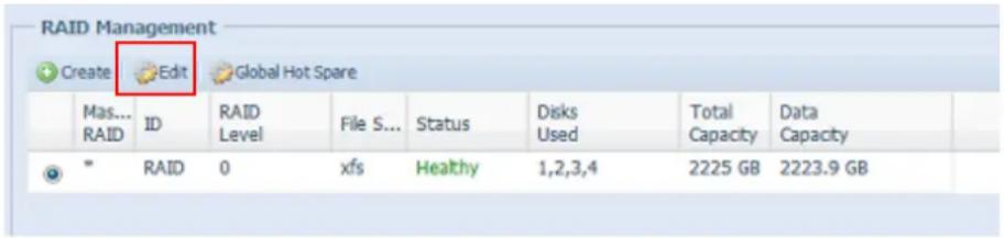
text_image
RAID Management Create Edit Global Hot Spare Mas... RAID ID RAID Level File S... Status Disks Used Total Data Capacity Capacity * RAID 0 xfs Healthy 1,2,3,4 2225 GB 2223.9 GB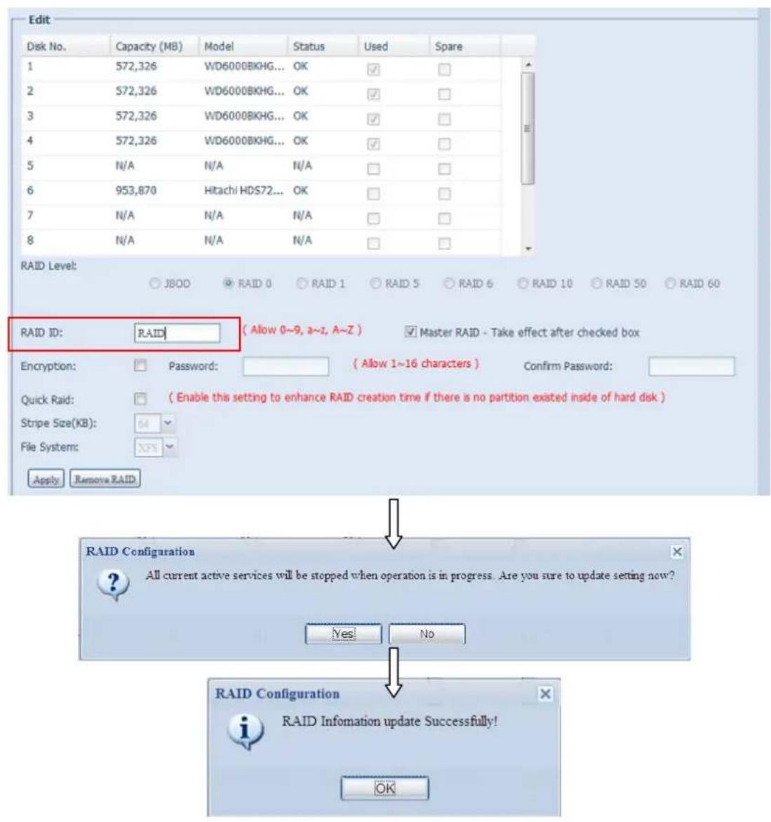
text_image
Edit Disk No. Capacity (MB) Model Status Used Spare 1 572,326 WD6000BKHG... OK ✓ 2 572,326 WD6000BKHG... OK ✓ 3 572,326 WD6000BKHG... OK ✓ 4 572,326 WD6000BKHG... OK ✓ 5 N/A N/A N/A ✓ 6 953,870 Hitachi HDS72... OK ✓ 7 N/A N/A N/A ✓ 8 N/A N/A N/A ✓ RAID Level: JBOO RAID 0 RAID 1 RAID 5 RAID 6 RAID 10 RAID 50 RAID 60 RAID ID: RAID ( Allow 0~9, a~Z, A~Z ) Master RAID - Take effect after checked box Encryption: Password: ( Allow 1~16 characters ) Confirm Password: Quick Raid: ( Enable this setting to enhance RAID creation time if there is no partition existed inside of hard disk ) Stripe Size(KB): 64 File System: Apply Remove RAID RAID Configuration All current active services will be stopped when operation is in progress. Are you sure to update setting now? Yes No RAID Configuration RAID Information update Successfully! OKRemove RAID
Click to remove the RAID volume. All user data and iSCSI created in the selected RAID volume will be deleted.
To remove a RAID volume, follow the steps below:
- On the RAID List screen, select the RAID volume by clicking on its radio button, and click RAID Information to open the RAID Configuration screen.
- On the RAID Configuration screen, click Remove RAID.
- A confirmation screen will appear, you will have to click "Yes" to complete the "Remove RAID" operation.
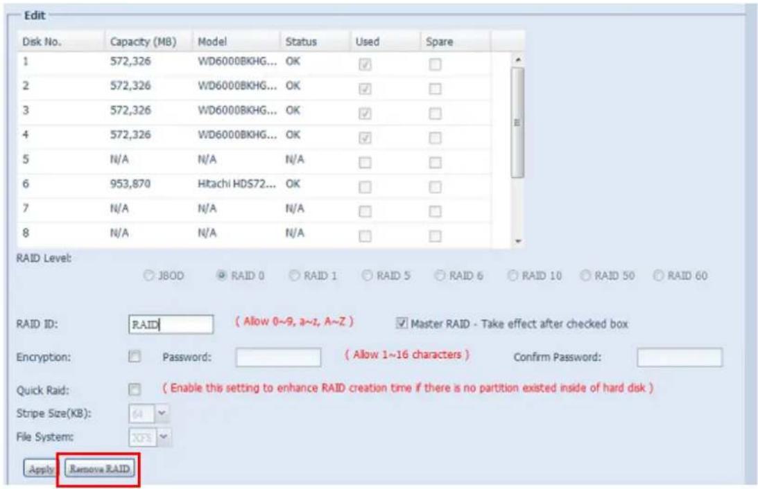
text_image
Edit Disk No. Capacity (MB) Model Status Used Spare 1 572,326 WD6000BKHG... OK ✓ ✓ 2 572,326 WD6000BKHG... OK ✓ ✓ 3 572,326 WD6000BKHG... OK ✓ ✓ 4 572,326 WD6000BKHG... OK ✓ ✓ 5 N/A N/A N/A ✓ ✓ 6 953,870 Hitachi HDS72... OK ✓ ✓ 7 N/A N/A N/A ✓ ✓ 8 N/A N/A N/A ✓ ✓ RAID Level: ○ JBOD ○ RAID 0 ○ RAID 1 ○ RAID 5 ○ RAID 6 ○ RAID 10 ○ RAID 50 ○ RAID 60 RAID ID: RAID ( Allow 0~9, a~z, A~Z ) Master RAID - Take effect after checked box Encryption: Password: ( Allow 1~16 characters ) Confirm Password: Quick Raid: ( Enable this setting to enhance RAID creation time if there is no partition existed inside of hard disk ) Stripe Size(KB): 64 File System: XCS Apply Remove RAIDWARNING
Remove RAID destroys all data in the selected RAID volume. The data will be unrecoverable.
Global Hot Spare
Up to 5 RAID volumes can be created per system. The global hot spare support can eliminate the redundant disk usage in each RAID volume. Simply select an unused disk from the global hot spare disk list then apply to activate.
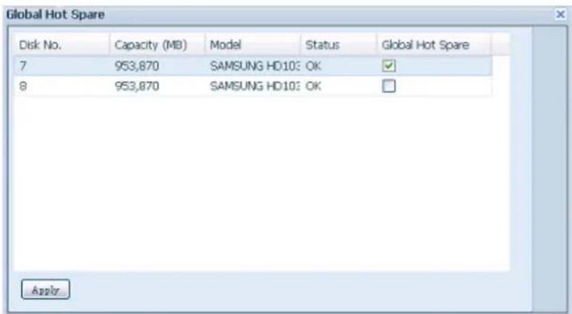
text_image
Global Hot Spare Disk No. Capacity (MB) Model Status Global Hot Spare 7 953,870 SAMSUNG HD10: OK 8 953,870 SAMSUNG HD10: OK ApplyExpanding a RAID
To expand a RAID 1, RAID 5, or RAID 6 volume, follow the steps below:
- Replace one of the hard drives in the RAID volume and allow it to automatically rebuild.
- Once rebuilt, you can continue to replace any remaining disks in the RAID array.
- When you are done replacing hard drives, log on to Web Management. Navigate to Storage> RAID to open the RAID Configuration screen.
- On the RAID Information screen, click Edit to open the RAID Configuration screen.
- On the RAID Configuration screen, click Expand.
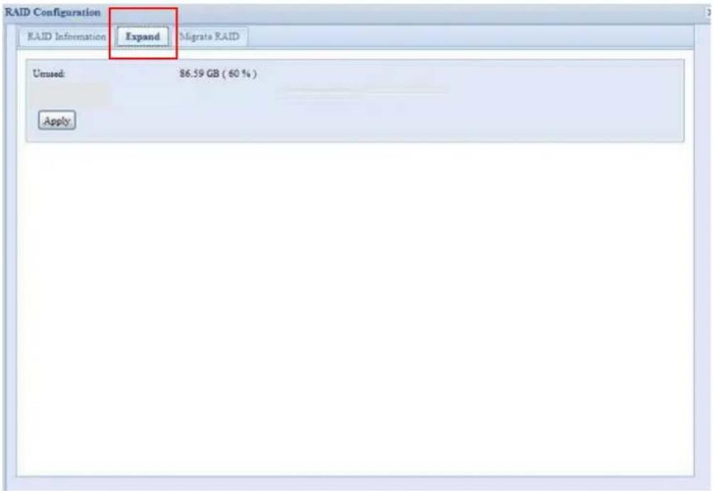
text_image
RAID Configuration RAID Information Expand Migrate RAID Unused: $6.59 GB ( 60 % ) ApplyMigrating a RAID
Once a RAID volume has been created, you may want to move it to other physical drives or change the RAID array all together. To migrate a RAID 1, RAID 5, RAID 6, RAID50 or RAID 60 volume, follow the steps below:
- From the RAID Configuration screen, click Migrate RAID.
- A list of possible RAID migration configurations will be listed. Select the desired migration scheme and click Apply.
- The system will begin migrating the RAID volume.
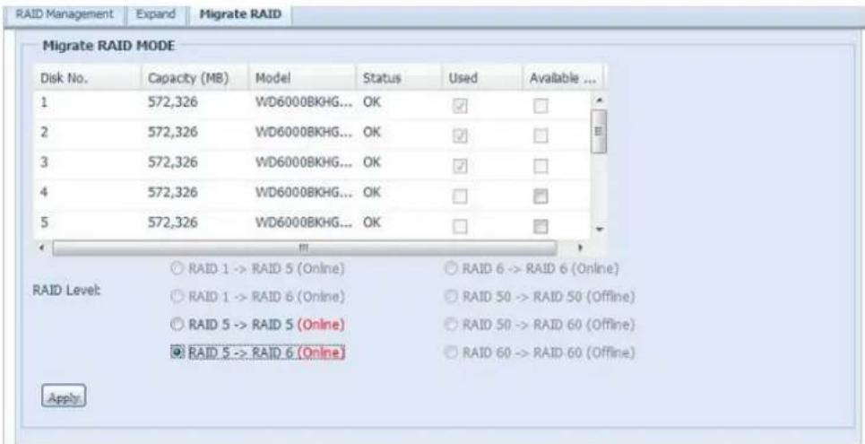
text_image
RAID Management Expand Migrate RAID Migrate RAID MODE Disk No. Capacity (MB) Model Status Used Available ... 1 572,326 WD6000BKHG... OK ✓ ✓ 2 572,326 WD6000BKHG... OK ✓ ✓ 3 572,326 WD6000BKHG... OK ✓ ✓ 4 572,326 WD6000BKHG... OK ✓ ✓ 5 572,326 WD6000BKHG... OK ✓ ✓ RAID Level: ○ RAID 1 -> RAID 5 (Online) ○ RAID 6 -> RAID 6 (Online) ○ RAID 1 -> RAID 6 (Online) ○ RAID 50 -> RAID 50 (Offline) ○ RAID 5 -> RAID 5 (Online) ○ RAID 50 -> RAID 60 (Offline) ● RAID 5 -> RAID 6 (Online) ○ RAID 60 -> RAID 60 (Offline) Apply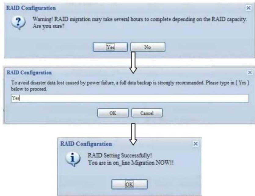
text_image
RAID Configuration Warning! RAID migration may take several hours to complete depending on the RAID capacity. Are you sure? Yes No RAID Configuration To avoid disaster data lost caused by power failure, a full data backup is strongly recommended. Please type in [ Yes ] below to proceed. Yes OK Cancel RAID Configuration RAID Setting Successfully! You are in on_line Migration NOW!! OKNOTE
■ Migrating a RAID volume could take several hours to complete
The RAID migration feature is available only when it is configurable.
Here is a list of limitation with RAID level migration function:
- During RAID level migration, it is not permitted to reboot or shutdown system.
- For RAID migration from R1 to R5 or R1 to R6, all services will restart and "iSCSI" volume will be in read only mode but read/write of the "user data" will be possible during the operation.
NOTE
The migration scheme below is based on Thecus IP Storage product's maximum possible combination. For other model which supports less HDD, please refer to the web UI while RAID migration operates.
Below is a table listing of possible RAID migration schemes:
| To From | RAID 0 | RAID 5 | RAID 6 |
| RAID 1 | [RAID 1] HDDx2 to [RAID 5] HDDx3[RAID 1] HDDx2 to [RAID 5] HDDx4[RAID 1] HDDx2 to [RAID 5] HDDx5[RAID 1] HDDx2 to [RAID 5] HDDx6[RAID 1] HDDx2 to [RAID 5] HDDx7[RAID 1] HDDx2 to [RAID 5] HDDx8......HDDx16[RAID 1] HDDx3 to [RAID 5] HDDx4[RAID 1] HDDx3 to [RAID 5] HDDx5[RAID 1] HDDx3 to [RAID 5] HDDx6[RAID 1] HDDx3 to [RAID 5] HDDx7[RAID 1] HDDx3 to [RAID 5] HDDx8......HDDx16[RAID 1] HDDx4 to [RAID 5] HDDx5[RAID 1] HDDx4 to [RAID 5] HDDx6[RAID 1] HDDx4 to [RAID 5] HDDx7[RAID 1] HDDx4 to [RAID 5] HDDx8......HDDx16[RAID 1] HDDx5 to [RAID 5] HDDx6[RAID 1] HDDx5 to [RAID 5] HDDx7[RAID 1] HDDx5 to [RAID 6] HDDx8......HDDx16[RAID 1] HDDx6 to [RAID 6] HDDx7[RAID 1] HDDx6 to [RAID 6] HDDx8......HDDx16[RAID 1] HDDx7 to [RAID 6] HDDx8......HDDx16 | [RAID 1] HDDx2 to [RAID 6] HDDx4[RAID 1] HDDx2 to [RAID 6] HDDx5[RAID 1] HDDx2 to [RAID 6] HDDx6[RAID 1] HDDx2 to [RAID 6] HDDx7[RAID 1] HDDx2 to [RAID 6] HDDx8......HDDx16[RAID 1] HDDx3 to [RAID 6] HDDx4[RAID 1] HDDx3 to [RAID 6] HDDx5[RAID 1] HDDx3 to [RAID 6] HDDx6[RAID 1] HDDx3 to [RAID 6] HDDx7[RAID 1] HDDx3 to [RAID 6] HDDx8......HDDx16[RAID 1] HDDx4 to [RAID 6] HDDx5[RAID 1] HDDx4 to [RAID 6] HDDx6[RAID 1] HDDx4 to [RAID 6] HDDx7[RAID 1] HDDx4 to [RAID 6] HDDx8......HDDx16[RAID 1] HDDx5 to [RAID 6] HDDx6[RAID 1] HDDx5 to [RAID 6] HDDx7[RAID 1] HDDx5 to [RAID 6] HDDx8......HDDx16[RAID 1] HDDx6 to [RAID 6] HDDx7[RAID 1] HDDx6 to [RAID 6] HDDx8......HDDx16[RAID 1] HDDx7 to [RAID 6] HDDx8......HDDx16 | |
| RAID 5 | X | [RAID 5] HDDx3 to [RAID 5] HDDx4[RAID 5] HDDx3 to [RAID 5] HDDx5[RAID 5] HDDx3 to [RAID 5] HDDx6[RAID 5] HDDx3 to [RAID 5] HDDx7[RAID 5] HDDx3 to [RAID 5] HDDx8......HDDx16[RAID 5] HDDx4 to [RAID 5] HDDx5[RAID 5] HDDx4 to [RAID 5] HDDx6[RAID 5] HDDx4 to [RAID 5] HDDx7[RAID 5] HDDx4 to [RAID 5] HDDx8......HDDx16[RAID 5] HDDx5 to [RAID 5] HDDx6[RAID 5] HDDx5 to [RAID 5] HDDx7[RAID 5] HDDx5 to [RAID 5] HDDx8......HDDx16[RAID 5] HDDx6 to [RAID 5] HDDx7[RAID 5] HDDx6 to [RAID 5] HDDx8......HDDx16[RAID 5] HDDx7 to [RAID 5] HDDx8......HDDx16 | [RAID 5] HDDx3 to [RAID 6] HDDx5[RAID 5] HDDx3 to [RAID 6] HDDx6[RAID 5] HDDx3 to [RAID 6] HDDx7[RAID 5] HDDx3 to [RAID 6] HDDx8......HDDx16[RAID 5] HDDx4 to [RAID 6] HDDx6[RAID 5] HDDx4 to [RAID 6] HDDx7[RAID 5] HDDx4 to [RAID 6] HDDx8......HDDx16[RAID 5] HDDx5 to [RAID 6] HDDx7[RAID 5] HDDx5 to [RAID 6] HDDx8......HDDx16[RAID 5] HDDx6 to [RAID 6] HDDx8......HDDx16 |
| RAID6 | X | X | [RAID 6] HDDx4 to [RAID 6] HDDx5[RAID 6] HDDx4 to [RAID 6] HDDx6[RAID 6] HDDx4 to [RAID 6] HDDx7[RAID 6] HDDx4 to [RAID 6] HDDx8......HDDx16[RAID 6] HDDx5 to [RAID 6] HDDx6[RAID 6] HDDx5 to [RAID 6] HDDx7[RAID 6] HDDx5 to [RAID 6] HDDx8......HDDx16[RAID 6] HDDx6 to [RAID 6] HDDx7[RAID 6] HDDx6 to [RAID 6] HDDx8......HDDx16[RAID 6] HDDx7 to [RAID 6] HDDx8......HDDx16 |
NAS Stacking
The Thecus IP storage's capacity can be expanded even further using the stackable function. With it, users can expand the capacity of their network storage systems up to 5 other stack target volumes which are located in different systems. These can be stacked through single network access like SMB or AFP acting as a share folder type.
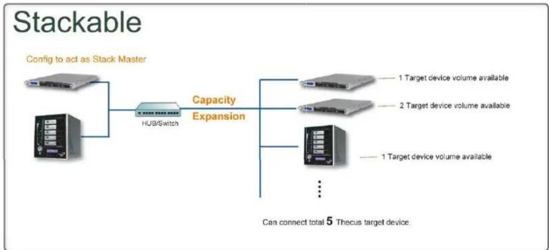
flowchart
graph LR
    A["Server"] --> B["HUB/Switch"]
    B --> C["Capacity Expansion"]
    C --> D["Server 1: 1 Target device volume available"]
    C --> E["Server 2: 2 Target device volume available"]
    C --> F["Server 3: 1 Target device volume available"]
    C --> G["..."]
    style A fill:#f9f,stroke:#333
    style B fill:#ccf,stroke:#333
    style C fill:#cfc,stroke:#333
    style D fill:#fcc,stroke:#333
    style E fill:#fcc,stroke:#333
    style F fill:#fcc,stroke:#333
    style G fill:#fcc,stroke:#333
    note right of C Can connect total 5 Thecus target device.
    note right of C Can connect total 5 Thecus target device.
    note right of A Config to act as Stack Master
From the main menu, the stackable feature is located under "Storage". Please refer the figure below for reference.
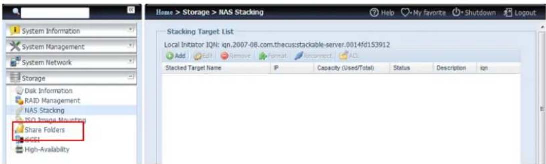
text_image
Home > Storage > NAS Stacking System Information System Management System Network Storage Disk Information RAID Management NAS Stacking ISO Image Mounting Share Folders ECEI High-Avalability Stacking Target List Local Initiator IQN: qqn.2007-08.com.thecus:stackable-server.0014fd153912 Add Edit Remove Format Recorrect ACL Stacked Target Name IP Capacity (Used/Total) Status Description ignA. Add a Stack Target Volume
From the figure above, click Add to access the stackable target device configuration page. Please refer to the figure below:
With the added stack target you can "Enable" or "Disable" the stack target now or later depending on usage required.
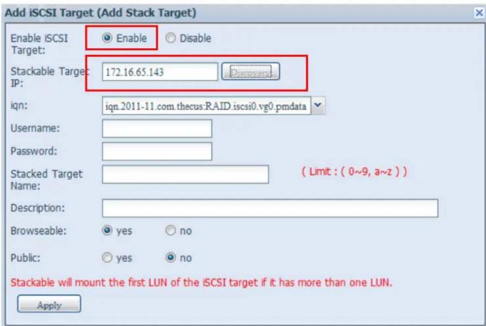
text_image
Add iSCSI Target (Add Stack Target) Enable iSCSI Target: Enable Disable Stackable Target: 172.16.65.143 ip: iqn: iqn.2011-11.com.thecus:RAID.iscsi0.vg0.pmdata Username: Password: Stacked Target Name: ( Limit : ( 0~9, a~z ) ) Description: Browseable: yes no Public: yes no Stackable will mount the first LUN of the iSCSI target if it has more than one LUN. ApplyNext, input the target IP address of the stackable device and click the Discovery button. The system will list available target volumes from the inputted IP address.
Once the volume IP has been set, you may need to input a valid user name and password to validate your access rights. If there is no user name and password needed to access target volume, then leave it blank.
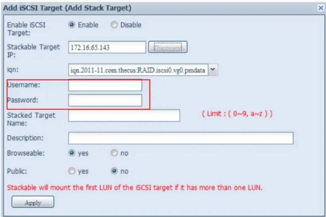
text_image
Add iSCSI Target (Add Stack Target) Enable iSCSI Target: Enable Disable Stackable Target IP: 172.16.65.143 iqn: iqn.2011-11.com.thecus:RAID.iscsi0.vg0.pmdata Username: Password: Stacked Target Name: ( Limit : ( 0~9, a~z ) ) Description: Browseable: yes no Public: yes no Stackable will mount the first LUN of the iSCSI target if it has more than one LUN. ApplyThe Stacked Target name will become the network share name and will be displayed through network access such as SMB. You may refer to the figure below to see the result. Please note the naming limitation.
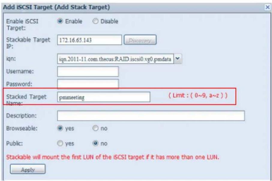
text_image
Add iSCSI Target (Add Stack Target) Enable iSCSI Target: Enable Disable Stackable Target IP: 172.16.65.143 Discovery iqn: iqn.2011-11.com.thecus:RAID.iscsi0.vg0.pmdata Username: Password: Stacked Target pmmeeting ( Limit : ( 0~9, a~z ) ) Name: Description: Browseable: yes no Public: yes no Stackable will mount the first LUN of the iSCSI target if it has more than one LUN. ApplyFrom the figure above, the Stacked Target name is "pmmeeting". The figures below show the result before and after via Microsoft Network Access when settings have been completed.
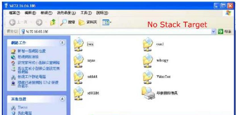
The Browseable setting is the same method used for setting a system share folder. It designates whether or not this folder will be visible through web disk. You may refer to the figure below for reference when Yes and No are selected.
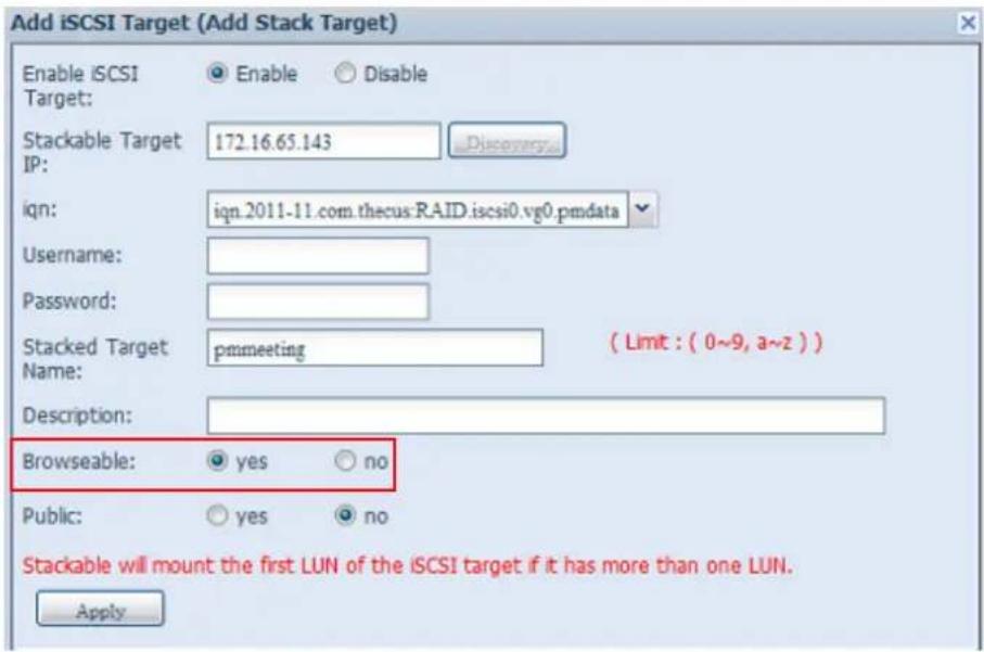
text_image
Add iSCSI Target (Add Stack Target) Enable iSCSI Target: Enable Disable Stackable Target IP: 172.16.65.143 Discovery iqn: iqn.2011-11.com.thecus:RAID.iscsi0.vg0.pmdata Username: Password: Stacked Target pmmeeting ( Limit : ( 0~9, a~z ) ) Name: Description: Browseable: yes no Public: yes no Stackable will mount the first LUN of the iSCSI target if it has more than one LUN. ApplyThe Public setting will be set the same way as the setting for the system share folder associated with the ACL permission is. If Public is set to Yes, all users will be able to access it, and ACL button will be grayed out. If Public is set to No, the ACL button will be available in the Stack Target List window.
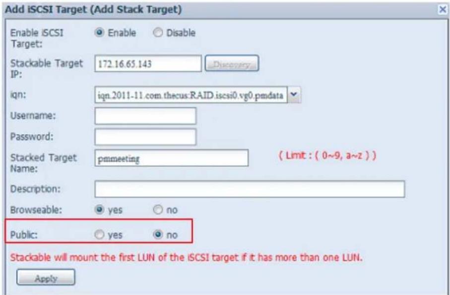
text_image
Add iSCSI Target (Add Stack Target) Enable iSCSI Target: Enable Disable Stackable Target IP: 172.16.65.143 Discovery iqn: iqn.2011-11.com.thecus:RAID.iscsi0.vg0.pmdata Username: Password: Stacked Target pmmeeting ( Limit : ( 0~9, a~z ) ) Name: Description: Browseable: yes no Public: yes no Stackable will mount the first LUN of the iSCSI target if it has more than one LUN. ApplyClick Apply to save your changes.
B. Activate a Stack Target
After your settings have been applied, the system will bring you back to the Stack Target List window as shown below. There is one stack target device that has been attached into this stack master.
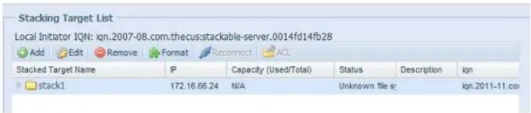
text_image
Stacking Target List Local Initiator IQN: qn.2007-08.com.thecus:stackable-server.0014fd14fb28 Add Edit Remove Format Retconnect AQL Stacked Target Name IP Capacity (Used/Total) Status Description qn stack1 172.16.66.24 N/A Unknown file s: qn.2011-11.cor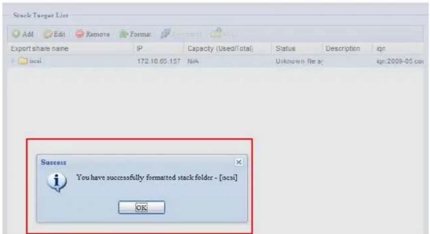
text_image
Stack Target List Add Edit Remove Format Export share name IP Capacity (Used/Total) Status Description ign iscsi 172.10.05-157 N/A Unknown file st: kn:2009-03.com Success You have successfully formatted stack folder - [iscsi] OKWith this newly attached stack target device, you will see the information displayed and also have access to several options to choose from.
In general, if the attached stack target device has been used by another Thecus NAS as stack target volume, then the Format item will be display and system will recognize it straight away and display its capacity. Otherwise, the Format item will be available and the Capacity and Status items will show as "N/A" and "Unknown file system" respectively.
Next, click Format to proceed with formatting.
After the format is completed, the stack target volume will be created successfully. You will see the volume's capacity and status in the Stack Target List screen.
C. Edit a Stack Target
To make any changes to a stack target, click Edit for the corresponding stack target, and the system will bring up the following dialogue window:
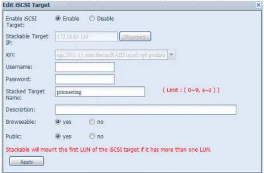
text_image
Edit iSCSI Target Enable iSCSI Target: Enable Disable Stackable Target IP: 172.16.65.143 Discoverys... iqn: iqn.2011-11.com.thescus.RAID.iscis0.vg0.pmdata Username: Password: Stacked Target pmmeeting ( Limit : ( 0~9, a~z ) ) Name: Description: Browseable: yes no Public: yes no Stackable will mount the first LUN of the iSCI target if it has more than one LUN. ApplyAfter your changes have been made, click Apply to confirm any modifications. Once changes are applied, the associated information will be updated on the Stack Target List window.
D. Stack Target ACL
If the stack target Public setting set to Yes, then the ACL button will be grayed out. However, if Public setting is set to No, then the ACL button will be available for you to setup user access permissions for the stack target.
The ACL settings will be exactly the same as the system folder that you may have setup previously.
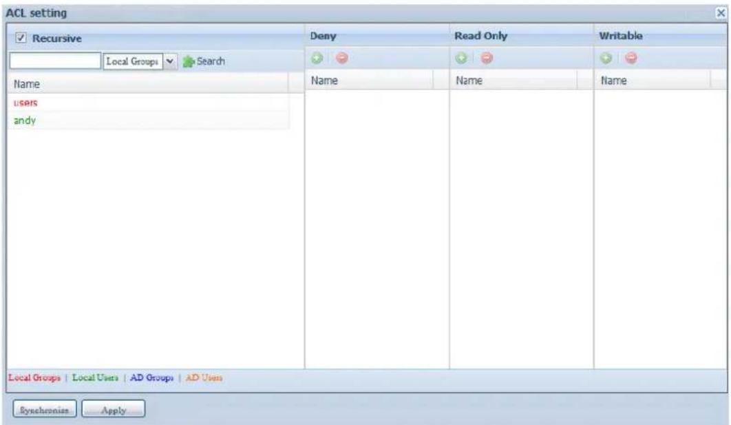
text_image
ACL setting ✓ Recursive Local Groups ✓ Search Name users andy Deny Read Only Writable Name Name Name Local Groups | Local Users | AD Groups | AD Users Synchronizes ApplyE. Reconnect a Stack Target
This is used to enable stack target devices that may have been disconnected due to a power outage or a disconnected network. When this happens, the Reconnect button will become available. To attempt to reconnect the stack target, click
Reconnect.
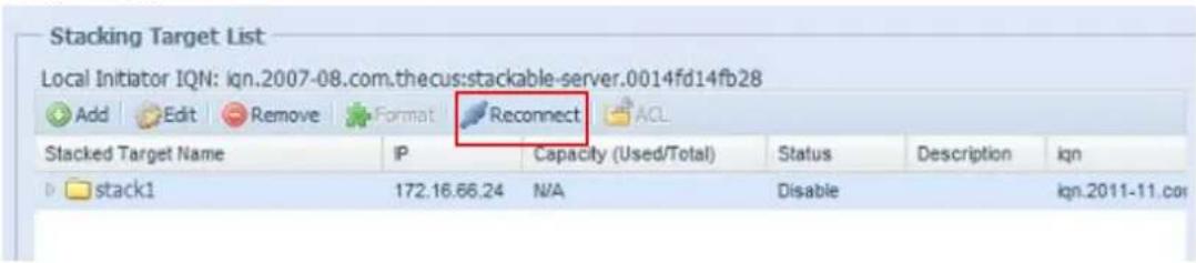
text_image
Stacking Target List Local Initiator IQN: ign.2007-08.com.thecus:stackable-server.0014fd14fb28 Add Edit Remove Format Reconnect ACL Stacked Target Name IP Capacity (Used/Total) Status Description ign stack1 172.16.66.24 N/A Disable iqn.2011-11.com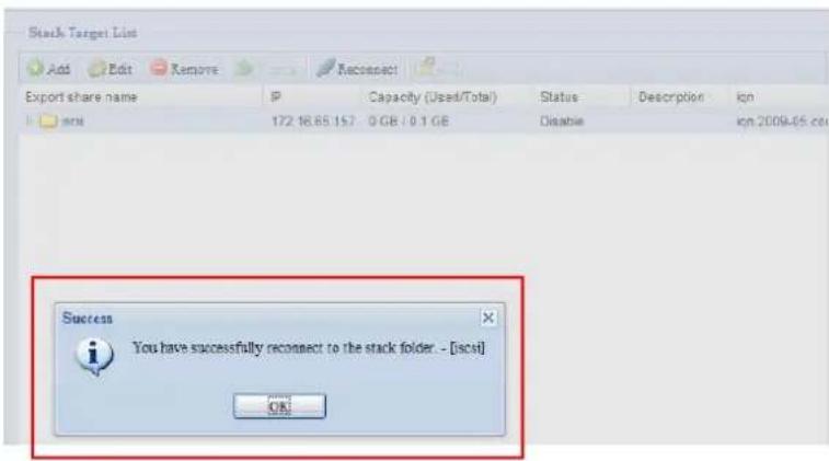
text_image
Stack Target List Add Edit Remove Reconnect Export share name IP Capacity (Used/Total) Status Description ign 172 16.65.157 0 GB / 0.1 GB Disase ign 2009-05.csc Success You have successfully reconnect to the stack folder. - [scst] OKISO Mount
The ISO Mount feature is a very useful tool from the Thecus products. With it, users can mount an ISO file and have the export name display all the details from the mounted ISO file.
From the main menu, the ISO Mount feature is located under "Storage". Please refer the figure below for reference.
Select the ISO Image Mounting function and the ISO Image Mounting window will appear as shown here.
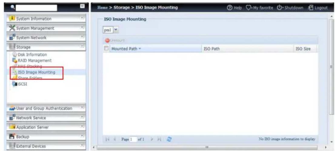
text_image
System Information System Management System Network Storage Disk Information RAID Management HAS Stacking ISO Image Mounting Share Folders ISCSI User and Group Authentication Network Service Application Server Backup External Devices Home > Storage > ISO Image Mounting Help My Favorite Shutdown Logout ISO Image Mounting pm1 Amount Mounted Path ISO Path ISO Size Page 1 of 1 No ISO image information to displayA. Add an ISO file
From the figure above, select an ISO file from the drop down share list.
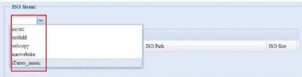
text_image
ISO Mount nsync usbhdd usbcopy naswebsite iTunes_music ISO Path ISO SizeAfter selection, the system will bring up the Mount table screen for further settings.
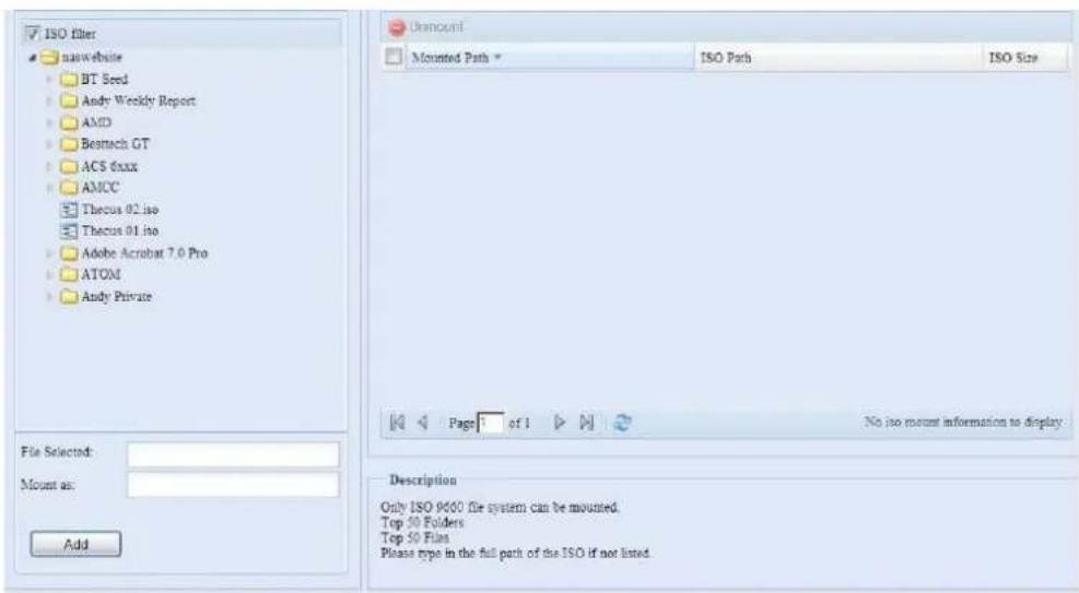
text_image
ISO filter naawebuile BT Seed Andy Weekly Report AMD Bestech GT ACS fixxx AMCC Thecus 02 iso Thecus 01 iso Adobe Acrobat 7.0 Pro ATOM Andy Private File Selected: Mount as: Add Amount Mounted Path * ISO Path ISO Size Page 1 of 1 No iso mount information to display. Description Only ISO 9600 file system can be mounted. Top 50 Folders Top 50 Files Please type in the full path of the ISO if not listed.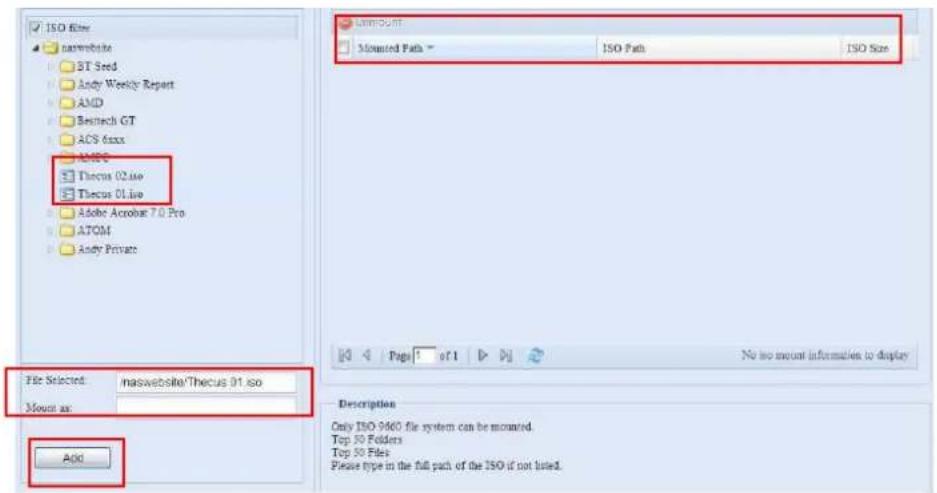
text_image
ISO Filter matewebite BT Seed Andy Weekly Report AMD Biotech GT ACS 6xxx AMBC Thecus 02.exe Thecus 01.exe Adobe Acrobat 7.0 Pro ATOM Andy Private File Selected: masewebite\Thecus 01.so Mount as: Add Amount Mounted Path > ISO Path ISO Size No too mount information to display Description Only ISO 9460 file system can be mounted. Top 30 Folders Top 50 Files Please type in the full path of the ISO if not listed.To mount the new ISO file, select one file from the list of files and input the desired mounting name into the "Mount as:" field. Click "ADD" to confirm the completion of the mounting. If nothing is input in the "Mount as" ISO file export name field, the system will automatically give an export name to the ISO file. The mounting name will then be defined by the ISO file name.
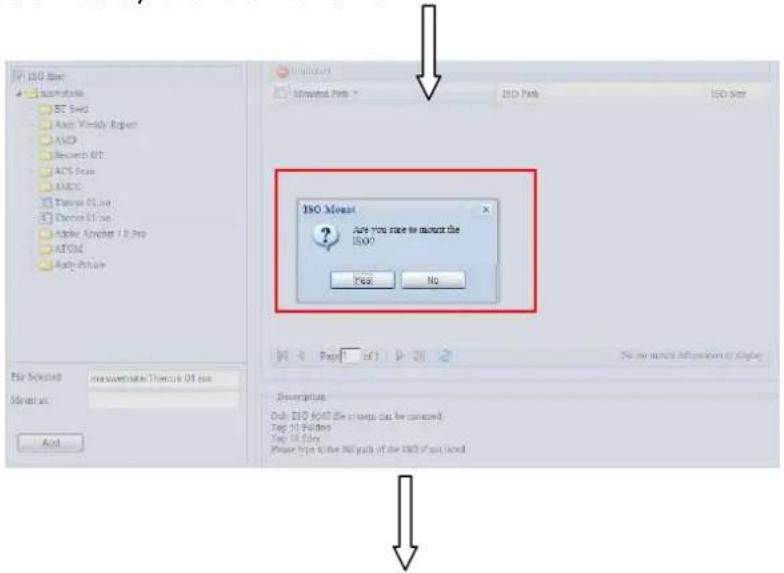
text_image
ISO Set Microsoft SET Set Auto Weekly Report AMD Research IEC ACS Scan AMCC Thesis 01.04 Decisions 01.04 Active Adapter 7.8 Pro ATOS4 Auto Price File Selected: Microsoft/Thesis 01.04 Solution: Add ISO Mount Are you sure to mount the ISO? Yes No Page 1 of 1 Name: name information by type Description: Only ISO 40.04 file groups can be consumed. Top 10 Pads Top 10 File Please type to the all paths of the ISO if not found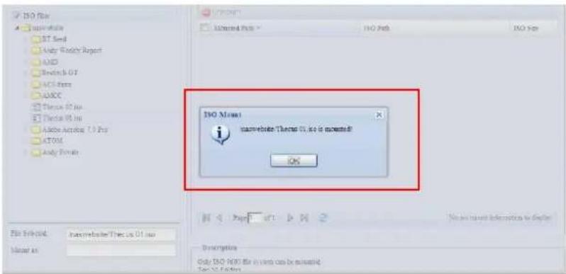
text_image
ISO File Importing ISO Send Auto Weekly Report ADD Switch Off ACI-Form ADCC Theroc 01 No Theroc 01 No Adobe Active ( ) Pro ATOM Auto Domain ISO Mount Anon website:Theroc 01, so is installed! OK File Set found: Inxepublote/Theroc 01.no Member as: No. on latest information to display. Description: Only ISO 900 file in this can be installed. Test 12 Edition.After completion, the page will display all mounted ISO files.
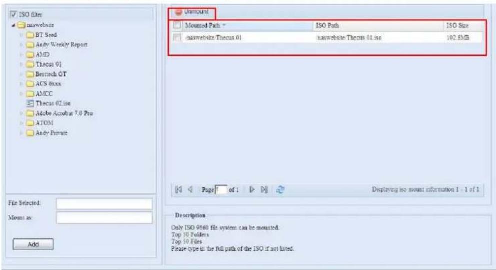
text_image
ISO files naswebsite BT Seed Andy Weekly Report AMD Thecus 01 Bestech GT ACS 8xxx AMCC Thecus 02.io Adobe Acrobat 7.0 Pro ATOM Andy Private File Selected: Mount as: Add Unmount Mounted Path ISO Path ISO Size naswebsite/Thecus 01 naswebsite-Thecus 01.io 102.83MB Page 1 of 1 Displaying iso mount information 1 - 1 of 1 Description Only ISO 9560 file system can be mounted. Top 10 Folders Top 50 Files Please type in the full path of the ISO if not listed.You can click "Unmount" to eliminate a mounted ISO file.
B. Using ISO
The mounted ISO file will be located in the share folder of the same name as the file. Please refer the screen shot below. Here, the ISO file "Thecus 01" wasn't assigned a mounting name, so the system automatically created a folder "Thecus 01".
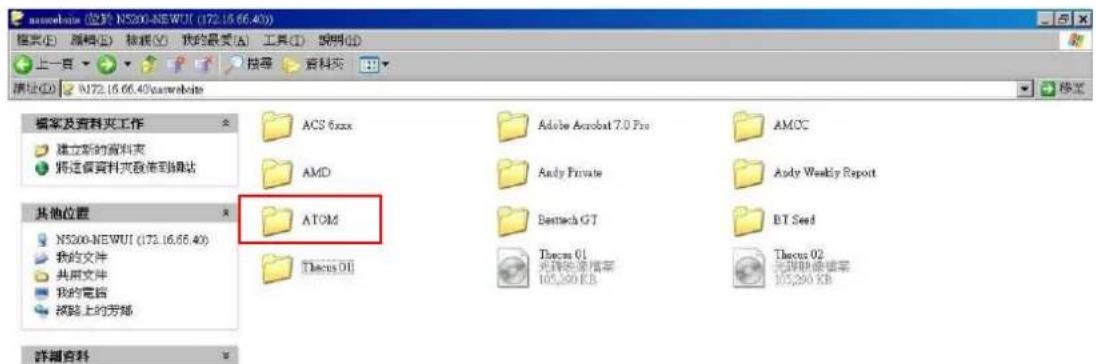
From the Storage menu, choose Share Folders, and the Shared Folder screen appears. This screen allows you to create and configure folders on the Thecus IP storage volume.
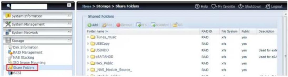
text_image
Home > Storage > Share Folders System Information System Management System Network Storage Disk Information RAID Management NAS Stacking ISO Image Mounting Share Folders GCSI Shared Folders Add Edit Remove NFS Snapshot ACL Folder name >> iTunes_music USBCopy USBHDD eSATAHDD NAS_Public _NAS_Module_Source_ RAID xfs yes RAID xfs yes RAID xfs yes RAID xfs yes RAID xfs yes RAID xfs yesAdding Folders
On the Folder screen, press the Add button and the Add Folder screen appears. This screen allows you to add a folder. After entering the information, press Apply to create new folder.
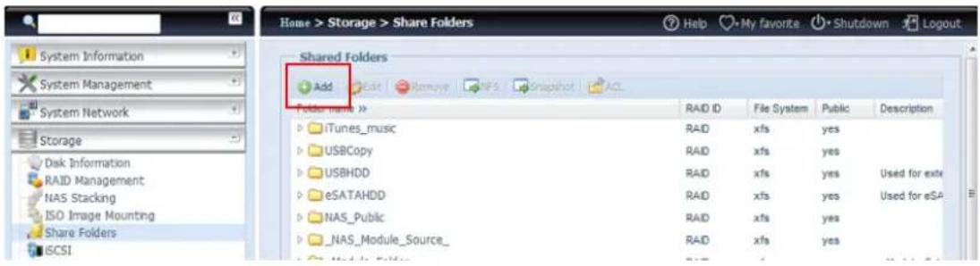
text_image
Home > Storage > Share Folders Help My favorite Shutdown Logout Shared Folders Add Folder name >> iTunes_music USBCopy USBHDD eSATAHDD NAS_Public _NAS_Module_Source_ RAID ID File System Public Description RAID xfs yes RAID xfs yes RAID xfs yes Used for exte RAID xfs yes Used for eSA RAID xfs yes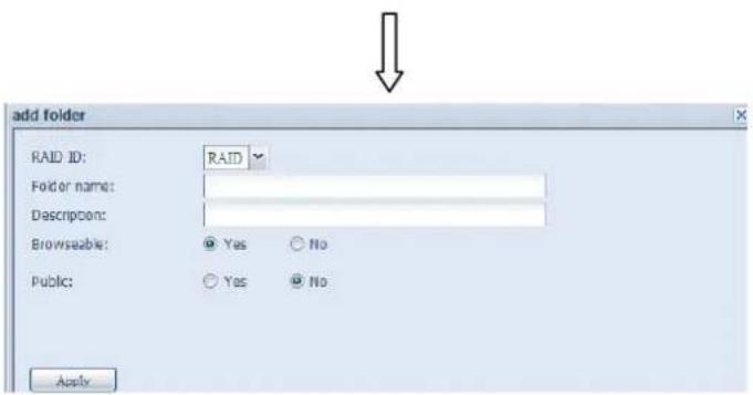
text_image
add folder RAID ID: RAID Folder name: Descricen: Browseable: Yes No Public: Yes No Apply| Add Folder | |
| Item | Description |
| RAID ID | RAID volume where the new folder will reside. |
| Folder Name | Enter the name of the folder. |
| Description | Provide a description the folder. |
| Browseable | Enable or disable users from browsing the folder contents. If Yes is selected, then the share folder will be browseable. |
| Public | Admit or deny public access to this folder. If Yes is selected, then users do not need to have access permission to write to this folder. When accessing a public folder via FTP, the behavior is similar to anonymous FTP. Anonymous users can upload/download a file to the folder, but they cannot delete a file from the folder. |
| Apply | Press Apply to create the folder. |
NOTE
Folder names are limited to 60 characters. Systems running Windows 98 or earlier may not support file names longer than 15 characters.
Modify Folders
On the Folder screen, press the Edit button and the Modify Folder screen appears. This screen allows you to change folder information. After entering the information, press Apply to save your changes.
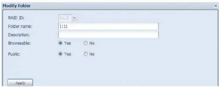
text_image
Modify Folder RAID ID: RAID Folder name: 1111 Description: Browseable: Yes No Public: Yes No Apply| Modify Folder | |
| Item | Description |
| RAID ID | RAID volume where the folder will reside. |
| Folder Name | Enter the name of the folder. |
| Description | Provide a description the folder. |
| Browseable | Enable or disable users from browsing the folder contents. This setting will only apply while access via SMB/CIFS and web disk. |
| Public | Admit or deny public access to this folder. |
Remove Folders
To remove a folder, press the Remove button from the specified folder row. The system will confirm folder deletion. Press Yes to delete the folder permanently or No to go back to the folder list.
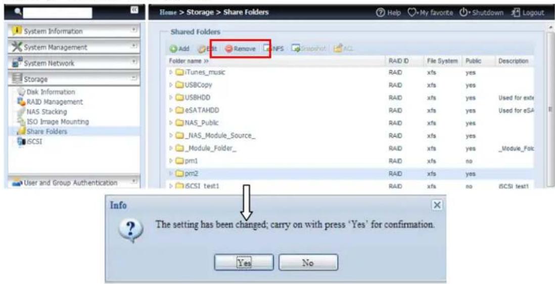
text_image
Home > Storage > Share Folders Help My favorite Shutdown Logout System Information System Management System Network Storage Disk Information RAID Management NAS Stacking ISO Image Mounting Share Folders iCSI User and Group Authentication Shared Folders Add Edit Remove NFS Snapshot ACL Folder name >> iTunes_music USBCopy USBHDD eSATAHDD NAS_Public _NAS_Module_Source_ _Module_Folder_ pm1 pm2 iCSI test1 RAID ID File System Public Description RAID xfs yes RAID xfs yes RAID xfs yes RAID xfs yes RAID xfs yes RAID xfs yes RAID xfs no RAID xfs yes RAID xfs no iCSI test1 Info The setting has been changed; carry on with press 'Yes' for confirmation. Yes NoWARNING
All the data stored in the folder will be deleted once the folder is deleted. The data will not be recoverable.
NFS Share
To allow NFS access to the share folder, enable the NFS Service, and then set up hosts with access rights by clicking Add.
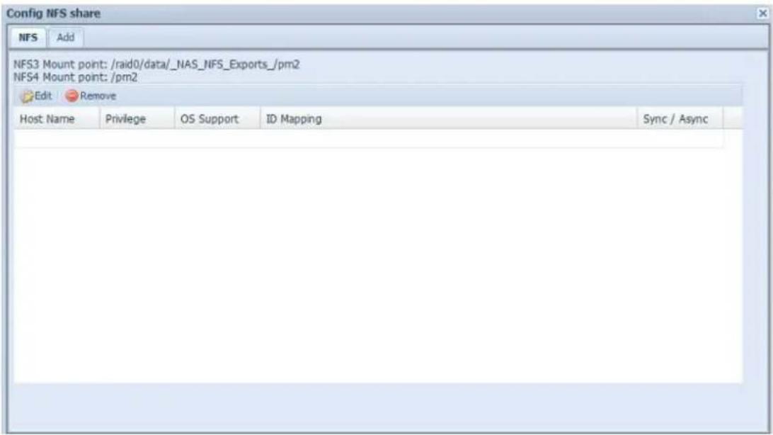
text_image
Config NFS share NFS Add NFS3 Mount point: /raid0/data/_NAS_NFS_Exports_/pm2 NFS4 Mount point: /pm2 Edit Remove Host Name Privilege OS Support ID Mapping Sync / Async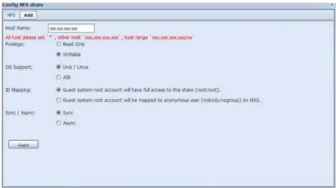
text_image
Config NFS share NF5 Add Host Name: xxx.xxx.xxx.xxx All host please set "==", other host 'xxx.xxx.xxx.xxx', host range 'xxx.xxx.xxx.xxx/xx' Privilege: ○ Read Only ● Writable OS Support: ● Unix / Linux ○ AIX ID Mapping: ● Guest system root account will have full access to this share (root:root). ○ Guest system root account will be mapped to anonymous user (nobody:nogroup) on NAS. Sync / Async: ● Sync ○ Async Apply| NFS Share | |
| Item | Description |
| Hostname | Enter the name or IP address of the host |
| Privilege | Host has either read only or writeable access to the folder. |
| OS Support | There are two selections available:Unix / Linux SystemAIX (Allow source port > 1024)Choose the one which best fits your needs. |
| ID Mapping | There are three selections available:Guest system root account will have full access to thisshare (root:root).Guest system root account will be mapped to anonymous user (nobody:nogroup) on NAS.All user on guest system will be mapped to anonymous user (nobody:nogroup) on NAS.Choose the one which best fits your needs. |
| Sync / Async | Choose to determine the data "Sync" at once or "Async" in arranged batch. |
| Apply | Click to save your changes. |
Folder and sub-folders Access Control List (ACL)
On the Folder screen, press the ACL button, and the ACL setting screen appears. This screen allows you to configure access to the specific folder and sub-folders for users and groups. Select a user or a group from the left hand column and then choose Deny, Read Only, or Writable to configure their access level. Press the Apply button to confirm your settings.
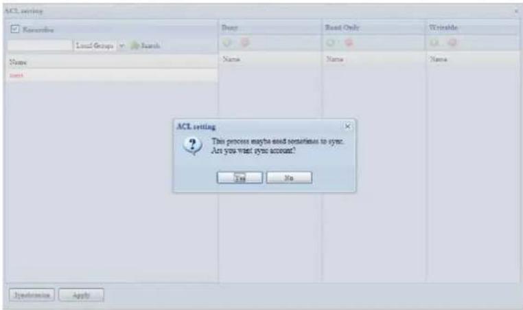
text_image
ACL setting Kategorie Load Groups Search Name read Darry Read Only Writable Name Name Name ACL setting This process may be used sometimes to sync. Are you want sync account? Yes No Automation Apply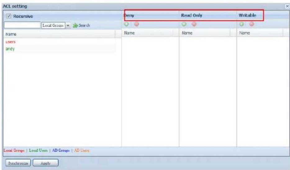
text_image
ACL setting ✓ Recursive Deny Read Only Writable Local Groups Search Name Name Name users andy Local Groups | Local Users | AD Groups | AD Users Synchronization Apply| ACL setting | |
| Item | Description |
| Deny | Denies access to users or groups who are displayed in this column. |
| Read Only | Provides Read Only access to users or groups who are displayed in this column. |
| Writable | Provides Write access to users or groups who are displayed in this column. |
| Recursive | Enable to inherit the access right for all its sub-folders. |
To configure folder access, follow the steps below:
-
On the ACL screen, all network groups and users are listed in the left hand column. Select a group or user from this list.
-
With the group or user selected, press one of the buttons from the three access level columns at the top. The group or user then appears in that column and has that level of access to the folder.
-
Continue selecting groups and users and assigning them access levels using the column buttons.
-
To remove a group or user from an access level column, press the Remove

button in that column.
- When you are finished, press Apply to confirm your ACL settings.
NOTE
If one user has belonged to more than one group with different privilege, then the priority of the privilege will be as followed:
Deny > Read Only > Writable
To setup sub-folders ACL, click on " ▶" symbol to extract sub folders list as screen shot shows below. You may carry on with same steps as share level ACL setting.
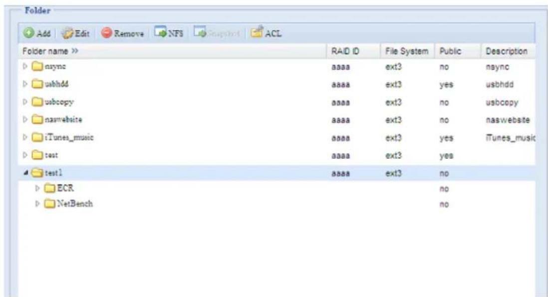
text_image
Folder Add Edit Remove NFS Snapshot ACL Folder name >> nsync usbhdd usbcopy naswebsite iTunes_music test test1 ECR NetBench RAID ID File System Public Description aaaa ext3 no nsync aaaa ext3 yes usbhdd aaaa ext3 no usbcopy aaaa ext3 no naswebsite aaaa ext3 yes iTunes_music aaaa ext3 yes aaaa ext3 no no noNOTE
The ACL can only be set for share and sub-folders level, not for files.
The ACL screen also allows you to search for a particular user. To do this, follow the steps below:
-
In the blank, enter the name of the user you would like to find.
-
From the drop down select the group you would like to search for the user in.
- Click Search.

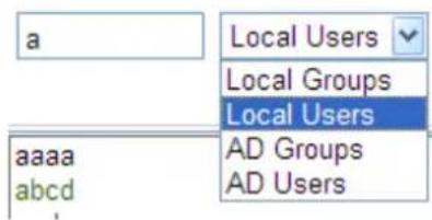
text_image
a Local Users Local Groups Local Users aaaa AD Groups abcd AD Users
NOTE
The system will list up to 1,000 users from the chosen category. To narrow your search, enter a search term in the blank provided.
Snapshot
SMB and enterprise Thecus IP storage systems are now capable of saving 16 Snapshot versions of files and folders. For Snapshot to function, a "BTRFS" file system is required.
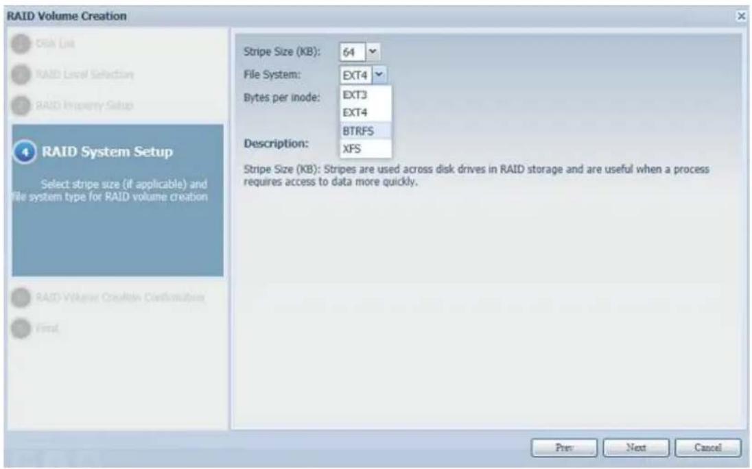
text_image
RAID Volume Creation 0500 OSN List 040 RAID Level Selection 030 RAID Property Setup RAID System Setup Select stripe size (if applicable) and file system type for RAID volume creation RAID WHERE Creation Confirmation Final Stripe Size (KB): 64 File System: EXT4 Bytes per inode: EXT3 EXT4 BTRFS Description: XFS Stripe Size (KB): Stripes are used across disk drives in RAID storage and are useful when a process requires access to data more quickly. Prev Next CancelAny folder using a "BTRFS" file system is capable of being included in the Snapshot function. In the "Share Folder" submenu, the Snapshot button is available in the tool bar.
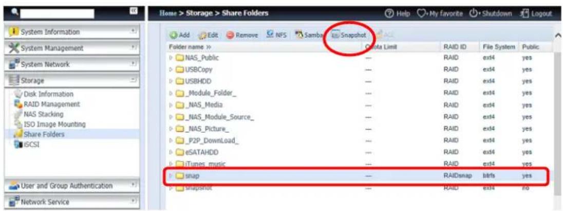
text_image
Home > Storage > Share Folders Add Edit Remove NFS Samba Snapshot Folder name > NAS_Public USBCopy USBHDD _Module_Folder_ NAS_Media NAS_Module_Source_ NAS_Picture_ P2P_DownLoad_ eSATAHDD iTunes_music snap Snapshok QA Data Limit RAID ID File System Public RAID ext4 yes RAID ext4 yes RAID ext4 yes RAID ext4 yes RAID ext4 yes RAID ext4 yes RAID ext4 yes RAID ext4 yes RAID ext4 yes RAID ext4 yes RAID ext4 yes RAID ext4 yes RAID ext4 yes RAID ext4 yes RAID ext4 yes RAID ext4 yes RAID ext4 yes RAIDext4 yes RAIDext4 noTaking a Snapshot
Click on the "Snapshot" button. The management screen will then appear as below for the associated folder.
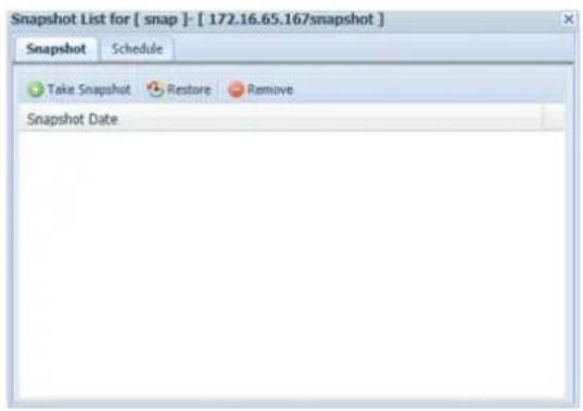
text_image
Snapshot List for [ snap ] - [ 172.16.65.167snapshot ] Snapshot Schedule Take Snapshot Restore Remove Snapshot DateTo manually take a Snapshot, simply click "Take Snapshot" and the Snapshot history will be listed. It can store up to 16 versions.
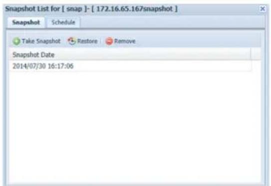
text_image
Snapshot List for [ snap ]- [ 172.16.65.167snapshot ] Snapshot Schedule Take Snapshot Restore Remove Snapshot Date 2014/07/30 16:17:06To locate where the Snapshot files or folders are stored, please browse to \System_IP\Snapshot. Please note that you will need to have the relevant folder permissions enabled for your account.
Besides manual Snapshots, this feature also allows for scheduled backups. Click on "Schedule" and the setup screen will appear. Check "Enable Snapshot Schedule"
and select the desired Snapshot interval. Options include Daily, Weekly, or Monthly.
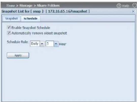
text_image
Name > Storage > Share Folders Snapshot List for [ snap ] - [ 172.16.65.167snapshot ] Snapshot Schedule Enable Snapshot Schedule Automatically remove oldest snapshot Schedule Rule: Daily 5 Hour ApplySince files and folders are limited to 16 Snapshots versions, the "Automatically remove oldest Snapshot" option allows for the removal of the oldest version automatically once the limit is reached.
√ Automatically remove oldest snapshot
Snapshot Restore
To restore a Snapshot, simply select the desired version from list and click "Restore". Once the restore confirmation has been made, the selected Snapshot will overwrite the current associated file or folder.
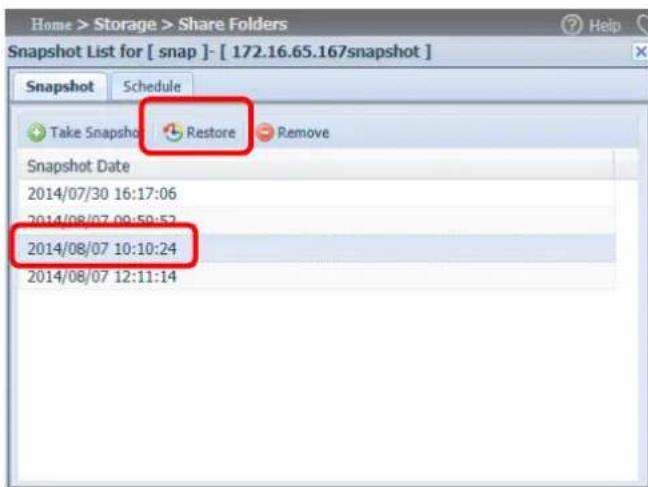
text_image
Home > Storage > Share Folders Snapshot List for [ snap ]- [ 172.16.65.167snapshot ] Snapshot Schedule Take Snapshot Restore Remove Snapshot Date 2014/07/30 16:17:06 2014/08/07 09:59:52 2014/08/07 10:10:24 2014/08/07 12:11:14The other way to restore a recorded Snapshot version is manually by browsing to the "Snapshot" folder via SAMBA (\System_IP\Snapshot). All Snapshot versions are stored here, and you can copy or paste to restore a version manually.
For example, the NAS system at 172.16.65.167 has a folder named "snap" with a Snapshot version backed up. If the user were to browse to \172.16.65.167\Snapshot, the following details would be visible:
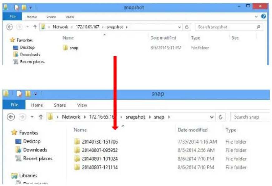
text_image
snapshot File Home Share View Network > 172.16.65.167 > snapshot > Search snapshot Favorites Desktop Downloads Recent places Name Date modified Type Size snap 8/5/2014 9:11 PM File folder snap File Home Share View Network > 172.16.65.16 > snapshot > snap > Search snap Favorites Desktop Downloads Recent places Name Date modified Type 20140730-161706 7/30/2014 1:16 AM File folder 20140807-095952 8/5/2014 2:56 AM File folder 20140807-101024 8/6/2014 7:10 PM File folder 20140807-121114 8/6/2014 7:10 PM File folderNOTE
To access the Snapshot folder, a user requires the relevant authentication rights.
NOTE
If the Snapshot folder is used for iSCSI purposes, it can only be restored from the WebUI (i.e. through the Snapshot feature) and cannot be done manually.
Snapshot Removal
To remove a Snapshot, simply select the desired version from list and click "Remove".
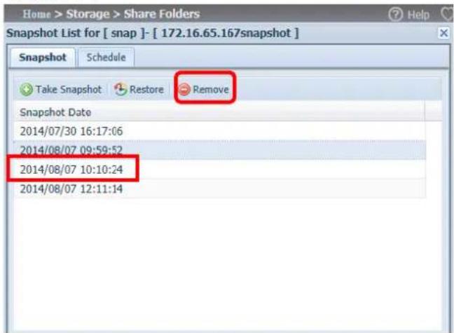
text_image
Home > Storage > Share Folders Snapshot List for [ snap ]- [ 172.16.65.167snapshot ] Snapshot Schedule Take Snapshot Restore Remove Snapshot Date 2014/07/30 16:17:06 2014/08/07 09:59:52 2014/08/07 10:10:24 2014/08/07 12:11:14iSCSI
You may specify the space allocated for iSCSI. See the table below to the allowed iSCSI target number per system:
| Model | N8900VN6850N5550N4510U seriesN7510 | N8800PRON12000VN16000VN7700PRO V2N8800PRO V2N7710 seriesN8810U seriesN10850N8850N5810N5810PRO | N8900N12000N16000N12000PRON16000PRON7770-10GN8880U-10G |
| Allowed iSCSI volume | 15 | 25 | 50 |
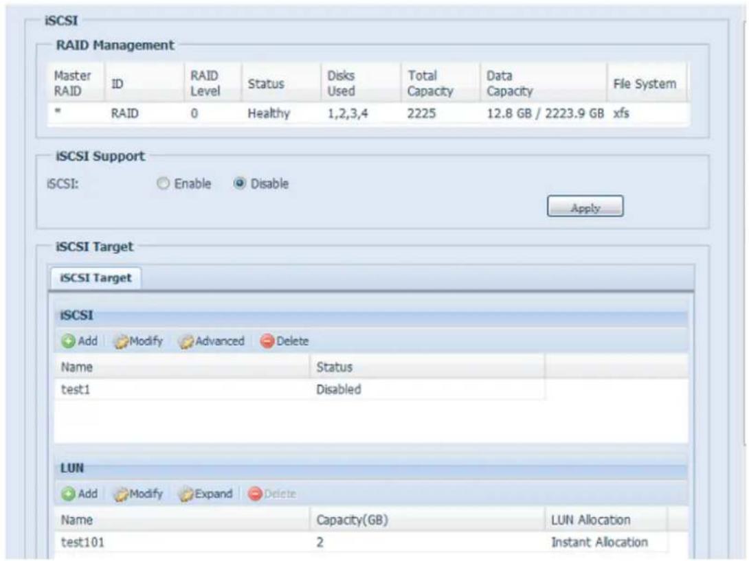
text_image
iSCSI RAID Management Master RAID ID RAID Level Status Disks Used Total Data Capacity Capacity File System * RAID 0 Healthy 1,2,3,4 2225 12.8 GB / 2223.9 GB xfs iSCSI Support iSCSI: Enable Disable Apply... iSCSI Target iSCSI Target iSCSI Add Modify Advanced Delete Name Status test1 Disabled LUN Add Modify Expand Delete Name Capacity(GB) LUN Allocation test101 2 Instant AllocationiSCSI Target
To add iSCSI target volume, click iSCSI with associated RAID volume from its drop down list and select the desired RAID volume.
| iSCSI Target | |
| Item | Description |
| Add | Click to allocate space to iSCSI target from associated RAID volume. |
| Modify | Click this to modify the iSCSI Target. |
| Advanced | There are 3 options (iSCSI CRC/Checksum, Max Connections, Error Recovery Level) These currently allowthe Admin to Enable/Disable the Thecus IP storage associated with the iSCSI setting. |
| Delete | Click this to delete the iSCSI Target. |
Allocating Space for iSCSI Volume
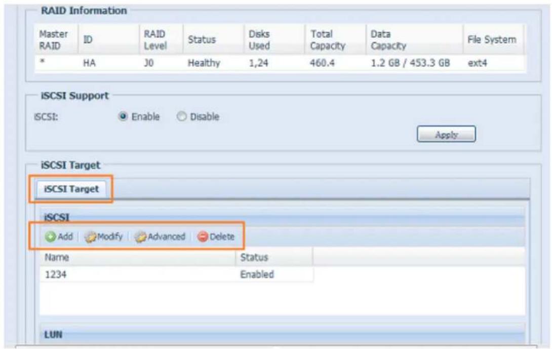
text_image
RAID Information Master RAID ID RAID Level Status Disks Used Total Data Capacity Capacity File System * HA J0 Healthy 1,24 460.4 1.2 GB / 453.3 GB ext4 iSCSI Support iSCSI: Enable Disable Apply iSCSI Target iSCSI Target iSCSI Add Modify Advanced Delete Name Status 1234 Enabled LUNTo allocate space for an iSCSI target on the current RAID volume, follow the steps below:
- Under the iSCSI Target List, select iSCSI Target then click Add. The Create iSCSI Volume screen appears.

text_image
Create iSCSI Volume SCSI Target Volume: Enable Disable Target Name: Limit:(0~9, a~z) qn_Year: 2010 qn_Month: 12 Authentication: None CHAP Username: Limit:(0~9, a~z, A~Z) Password: Limit:(0~9, a~z, A~Z, length between 12~16) Password Confirm: Mutual CHAP Username: Limit:(0~9, a~z, A~Z) Password: Limit:(0~9, a~z, A~Z, length between 12~16) Password Confirm: Create LUN RAID ID: RAID LUN Allocation: Thin-Provision Instant Allocation LUN Name: Limit:(0~9, a~z) Unused: 363 GB Allocation: 1 GB LUN ID: 0 SCSI Block size: 512 Bytes(For older version) Description The iSCSI block size can be set under system advance option, default is 512 Bytes. Please use [4K] block size while more than 2TB capacity will be configured in Windows XP. Please use [512 Bytes] block size for application like VMware etc. OK| Create iSCSI Volume | |
| Item | Description |
| iSCSI Target Volume | Enable or Disable the iSCSI Target Volume. |
| Target Name | Name of the iSCSI Target. This name will be used by the Stackable NAS function to identify this export share. |
| iqn_Year | Select the current year from the dropdown. |
| Iqn_Month | Select the current month from the dropdown. |
| Authentication | You may choose CHAP authentication or choose None. |
| Username | Enter a username. |
| Password | Enter a password. |
| Password Confirm | Reenter the chosen password |
| Mutual CHAP | With this level of security, the target and the initiator authenticate each other. |
| Username | Enter a username. |
| Password | Enter a password. |
| Password Confirm | Reenter the chosen password |
| RAID ID | ID of current RAID volume. |
| LUN Allocation | Two modes can be choose from:Thin-provision : iSCSI thin-provisioning shares the available physical capacity to multiple iSCSI target volumes. It allows virtual capacity to be assigned to targets prior to adding physical space when it has run out.Instant Allocation: Allocate available physical capacity to iSCSI target volumes. |
| LUN Name | Name of the LUN. |
| Unused | Unused space on current RAID volume. |
| Allocation | Percentage and amount of space allocated to iSCSI volume. |
| LUN ID | Specific Logic unit ID number. |
| iSCSI Block size | The iSCSI block size can be set under system advance option, default is 512 Bytes.[ 4K ] block size while more than 2TB capacity will be configured in Windows XP.[ 512 Bytes ] block size for application like VMware etc. |
NOTE
Be sure the iSCSI target volume has been enabled or it will not list out while using Initiator to get associated iSCSI target volumes.
NOTE
The iSCSI target volume creation will associate at least one LUN together. It can be assigned either "Thin-Provisioning" or "Instant Allocation".
- Enable the iSCSI Target Volume by selecting Enable.
- Enter a Target Name. This will be used by the Stackable NAS function to identify this export share.
- Choose the current year from the Year dropdown.
- Choose the current month from the Month dropdown.
- Choose to enable CHAP authentication or choose None.
- If you've enabled CHAP authentication, enter a username and a password. Confirm your chosen password be reentering it in the Password Confirm box.
- Choose Thin-Provision or Instant Allocation
- Enter a LUN Name.
- Designate the percentage to be allocated from the Allocation drag bar.
- When iSCSI target volume has been created, the LUN ID is configurable from 0 to 254 with a default of the next available number in ascending numerical order. The LUN ID is unique and cannot be duplicated.
- Choose [4K] block size to have iSCSI target volume over 2TB barrier or [512 Bytes] block size in some application needed.
- Click OK to create the iSCSI volume.
Modify iSCSI Volume
To modify iSCSI target on the current RAID volume, follow the steps below:
- Under the iSCSI Target List, click Modify.
The Modify iSCSI Volume screen appears.
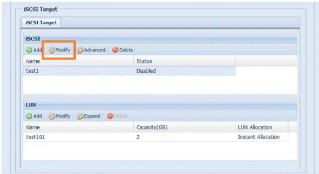
text_image
iSCSI Target iSCSI Target iSCSI Add Modify Advanced Delete Name Status test1 Disabled LUN Add Modify Expand Delete Name Capacity(GB) LUN Allocation test101 2 Instant Allocation- Modify your settings. Press ok to change.
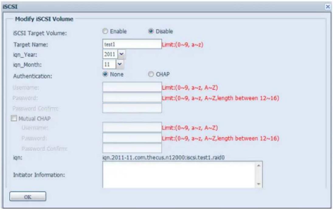
text_image
iSCSI Modify iSCSI Volume iSCSI Target Volume: Enable Disable Target Name: test1 Limit:(0~9, a~z) iqn_Year: 2011 iqn_Month: 11 Authentication: None CHAP Username: Limit:(0~9, a~z, A~Z) Password: Limit:(0~9, a~z, A~Z,length between 12~16) Password Confirm: Mutual CHAP Username: Limit:(0~9, a~z, A~Z) Password: Limit:(0~9, a~z, A~Z,length between 12~16) Password Confirm: iqn: ign.2011-11.com.thecus.n12000:icsi.test1.raid0 Initiator Information: OKExpand Volume
The iSCSI volume is now able to expand its capacity from unused space (Instant Allocation mode only). From the volume list, simply select the iSCSI volume you like to expand and click the Expand button:
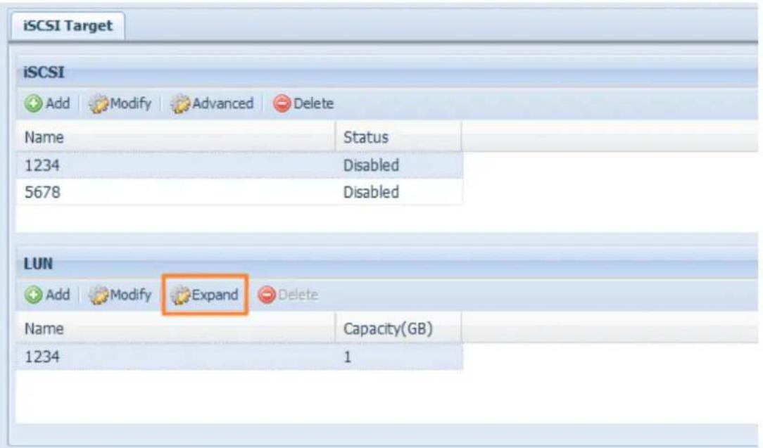
text_image
iSCSI Target iSCSI Add Modify Advanced Delete Name Status 1234 Disabled 5678 Disabled LUN Add Modify Expand Delete Name Capacity(GB) 1234 1You will then see the dialog box displayed below. Drag the Expand Capacity bar to the size you want. Then press Expand to confirm the operation.
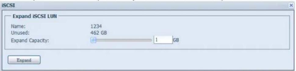
text_image
iSCSI Expand iSCSI LUN Name: 1234 Unused: 462 GB Expand Capacity: 1 GB ExpandDelete Volume
To delete volume on the current RAID volume, follow the steps below:
- Under the Volume Allocation List, click Delete. The Space Allocation screen appears.
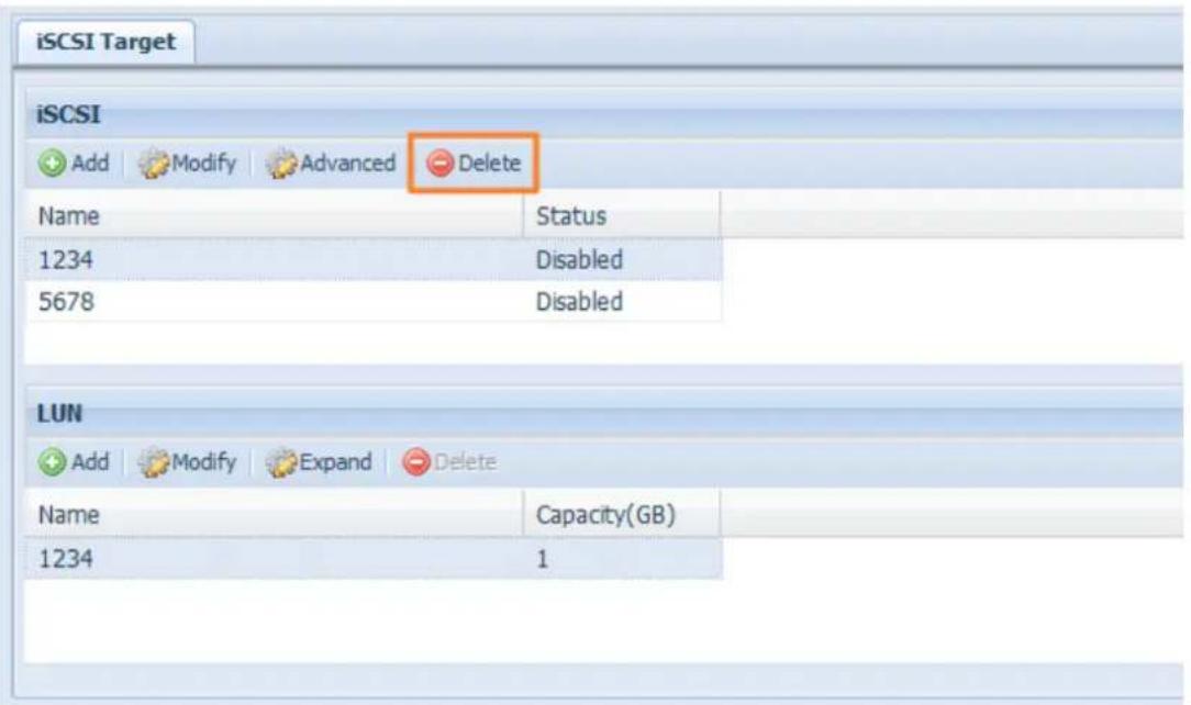
text_image
iSCSI Target iSCSI Add Modify Advanced Delete Name Status 1234 Disabled 5678 Disabled LUN Add Modify Expand Delete Name Capacity(GB) 1234 1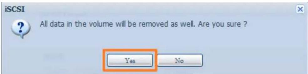
text_image
iSCSI All data in the volume will be removed as well. Are you sure ? Yes No- Press YES. All data in the volume will be removed.
iSCSI Thin-Provisioning
If iSCSI Thin-Provisioning is selected when creating an iSCSI target volume, virtual memory is assigned to the target, allowing the physical memory to reach maximum capacity and adding new disks only when needed.
To setup iSCSI thin-provisioning, simply select "Thin-Provision" mode from the "Create LUN" setting screen.
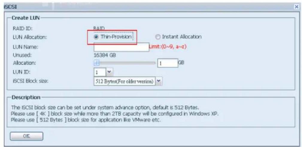
text_image
ISCSI Create LUN RAID ID: RAID LUN Allocation: Thin-Provision LUN Name: Limit:(0~9, a~2) Unused: 16384 GB Allocation: 1 GB LUN ID: 1 ISCSI Block size: 512 Bytes(For older version) Description The ISCSI block size can be set under system advance option, default is 512 Bytes. Please use [ 4K ] block size while more than 2TB capacity will be configured in Windows XP. Please use [ 512 Bytes ] block size for application like VMware etc. OKNext, allocate capacity for the iSCSI thin-provision volume by dragging the Allocation bar to the desired size.
After the size has been determined, click OK to confirm. Now you will see the iSCSI thin-provisioning volume is available from the list. Please refer to the screenshot below.
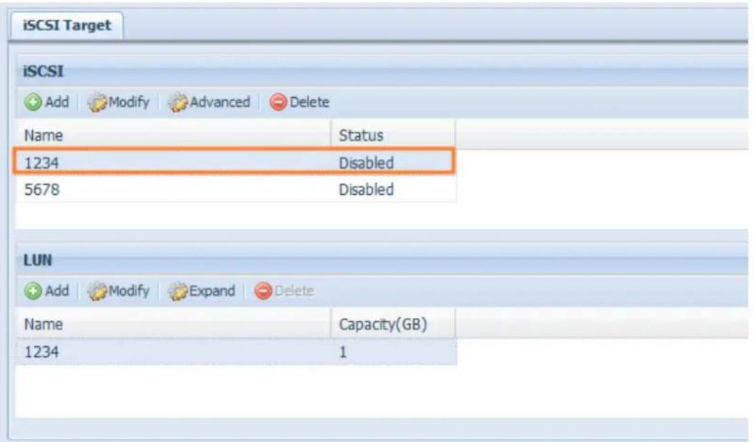
text_image
iSCSI Target iSCSI Add Modify Advanced Delete Name Status 1234 Disabled 5678 Disabled LUN Add Modify Expand Delete Name Capacity(GB) 1234 1If creating an iSCSI target volume under "Instant Allocation", physical memory is assigned to the target, being limited by the available memory. For the iSCSI target volume created under "thin-provisioning", virtual memory is assigned to the volume, which can go up to 16384GB (16TB).
Advance Option
There are 3 available options for the user to operate Thecus IP storage associated with iSCSI setting. The details are listed in the following screenshot. If the options are modified, the system will need to reboot for the changes to take place.
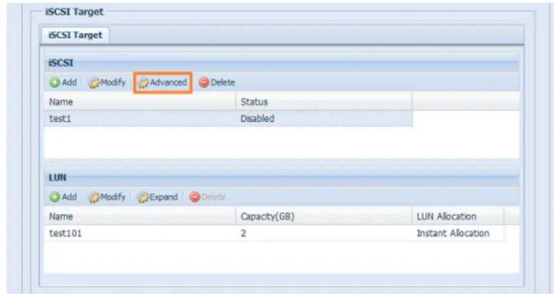
text_image
iSCSI Target iSCSI Target iSCSI Add Modify Advanced Delete Name Status test1 Disabled LUN Add Modify Expand Delete Name Capacity(GB) LUN Allocation test101 2 Instant AllocationiSCSI CRC/Checksum
To enable this option, the initiator can connect with "Data digest" and "Header digest".
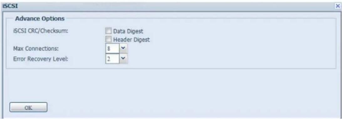
text_image
iSCSI Advance Options iSCSI CRC/Checksum: Data Digest Header Digest Max Connections: 8 Error Recovery Level: 2 OKMax Connections
The maximum number of iSCSI connections.
Error Recovery Level
The Error Recovery Level (ERL) is negotiated during a leading iSCSI connection login in traditional iSCSI (RFC 3720) and iSER (RFC 5046).
ERL=0: Session Recovery
ERL=0 (Session Recovery) is triggered when failures within a command, within a connection, and/or within TCP occur. This causes all of the previous connections from the failed session to be restarted on a new session by sending a iSCSI Login Request with a zero TSIHRestart all iSCSI connections on any failure.
ERL=1: Digest Failure Recovery
ERL=1, only applies to traditional iSCSI. For iSCSI/SCTP (which has its own CRC32C) and both types of iSER (so far), handling header and data checksum recovery can be disabled.
ERL=2: Connection Recovery
ERL=2, allows for both single and multiple communication path sessions within a iSCSI Nexus (and hence the SCSI Nexus) to actively perform realligence/retry on iSCSI ITTs from failed iSCSI connections. ERL=2 allows iSCSI fabrics to take advantage of recovery in all regards of transport level fabric failures, and in a completely OS independent fashion (i.e. below the host OS storage stack).
Disk Clone and Wipe
Disks installed on this device are able to utilize the Disk Clone and Wipe function
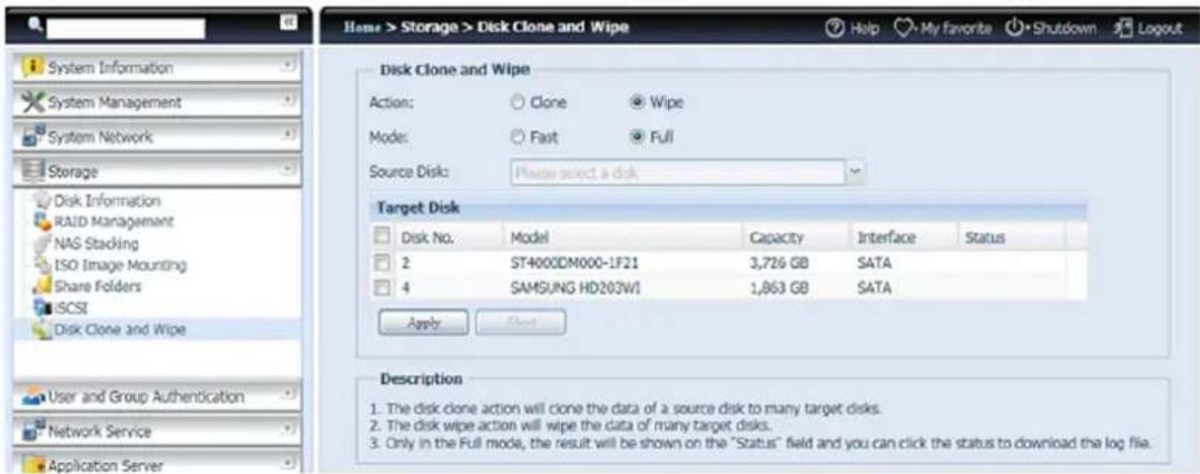
text_image
Home > Storage > Disk Clone and Wipe System Information System Management System Network Storage Disk Information RAID Management NAS Stacking ISO Image Mounting Share Folders SCSI Disk Clone and Wipe User and Group Authentication Network Service Application Server Disk Clone and Wipe Action: Clone Wipe Mode: Fast Full Source Disk: Please select a disk Target Disk Disk No. Model Capacity Interface Status 2 ST4000DM000-1F21 3,726 GB SATA 4 SAMSUNG HD203W1 1,863 GB SATA Apply Apply Description 1. The disk clone action will clone the data of a source disk to many target disks. 2. The disk wipe action will wipe the data of many target disks. 3. Only in the Full mode, the result will be shown on the "Status" field and you can click the status to download the log file.Disk Clone:
Unused Disks that have been installed on this storage device can utilize the disk clone function. If disks have already been configured in a RAID volume or as a spare disk, they cannot perform disk clone.
To start disk clone, select the source disk from the drop down menu and target a disk from the dialog box as seen below. Carry on to press "Apply," then the task will start. It may take a few hours depending on the size of the disk.
Please be sure the source disk is equal to or smaller than the target disk.
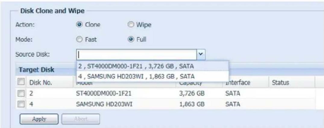
text_image
Disk Clone and Wipe Action: Clone Wipe Mode: Fast Full Source Disk: Target Disk 2, ST4000DM000-1F21, 3,726 GB, SATA 4, SAMSUNG HD203WI, 1,863 GB, SATA Disk No. Model Capacity Interface Status 2 ST4000DM000-1F21 3,726 GB SATA 4 SAMSUNG HD203WI 1,863 GB SATA Apply AbortDisk Wipe:
Disk Wipe is able to erase data from selected disks. Again, disks that have already been configured in a RAID volume or as a spare disk cannot perform this function.
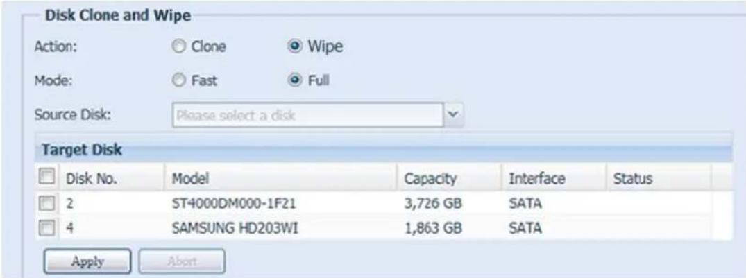
text_image
Disk Clone and Wipe Action: Clone Wipe Mode: Fast Full Source Disk: Please select a disk Target Disk Disk No. Model Capacity Interface Status 2 ST4000DM000-1F21 3,726 GB SATA 4 SAMSUNG HD203WI 1,863 GB SATA Apply Abort| Disk Clone and Wipe | |
| Item | Description |
| Action | Click to choose to perform Disk Clone or Disk Wipe |
| Mode | 2 options can be chosen:Fast: suitable for single disk to many tasks but less information to be displayedFull: suitable for single to single disk operation and will have a complete log recorded during operation |
| Source Disk | Listed available disks can used as the source disk while performing disk clone |
| Target Disk | Listed available disks can be used for disk clone or disk wipe |
| Apply | To save your settings. |
High-Availability (N8900, N12000 series/N16000 series only)
HA keeps your data active on two separate systems, Thecus Supports Active/Passive HA — provides a fully redundant instance of each node, which is only brought online when its associated primary node fails.
HA setup procedure:
HA needs two identical Thecus systems (same models and same hard disk slot installed) which are capable for high availability features. One needs to be setup as "Primary" and the second unit as "Secondary", both units' needs to have the RAID volume build up prior installation.
WARNING
Please be notified that if the system has been used as a standalone station before and contained more than one RAID volume with data inside, once it is used for HA, all of data will be destroyed.
Let's see an example with two Thecus Units.
1^st unit: Host name: PMA (172.16.66.25) with JBOD RAID volume. This unit will be setup as the Primary server.
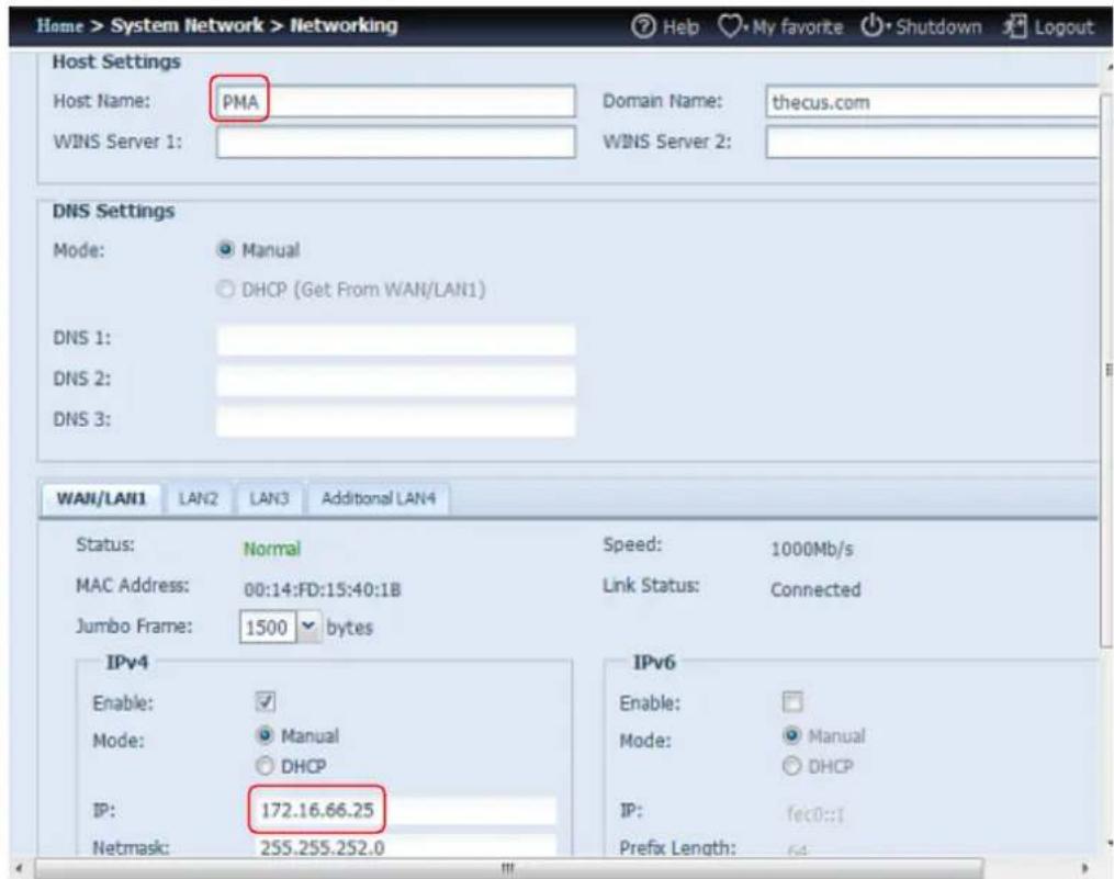
text_image
Home > System Network > Networking Host Settings Host Name: PMA Domain Name: thecus.com WINS Server 1: WINS Server 2: DNS Settings Mode: Manual DHCP (Get From WAN/LAN1) DNS 1: DNS 2: DNS 3: WAN/LAN1 LAN2 LAN3 Additional LAN4 Status: Normal Speed: 1000Mb/s MAC Address: 00:14:FD:15:40:1B Link Status: Connected Jumbo Frame: 1500 bytes IPv4 Enable: ✓ Mode: Manual DHCP IP: 172.16.66.25 Netmask: 255.255.252.0 IPv6 Enable: Mode: Manual DHCP IP: fec0::1 Prefix Length: 64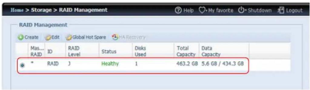
text_image
Home > Storage > RAID Management RAID Management Create Edit Global Hot Spare HA Recovery Mas... RAID ID RAID Level Status Disks Used Total Data Capacity Capacity * RAID J Healthy 1 463.2 GB 5.6 GB / 434.3 GB2 ^nd unit: Host name: PMS (172.16.66.24) with JBOD RAID volume. This unit will be setup as the Secondary server.
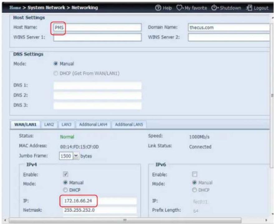
text_image
Home > System Network > Networking Host Settings Host Name: PMS WIN5 Server 1: Domain Name: thecus.com WIN5 Server 2: DNS Settings Mode: Manual DHCP (Get From WAN/LAN1) DNS 1: DNS 2: DNS 3: WAN/LAN1 LAN2 LAN3 Additional LAN4 Additional LAN5 Status: Normal MAC Address: 00:14:FD:15:CF:0D Jumbo Frame: 1500 bytes Speed: 1000Mb/s Link Status: Connected IPv4 Enable: Mode: Manual DHCP IP: 172.16.66.24 Netmask: 255.255.252.0 IPv6 Enable: Mode: Manual DHCP IP: fec0:1 Prefix Length: 64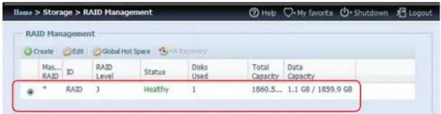
text_image
RAID Management Create Edit Global Hot Spare HA Recovery Mas... RAID ID RAID Level Status Disks Used Total Capacity Data Capacity * RAID J Healthy 1 1860.5... 1.1 GB / 1859.9 GBWARNING
The HDD capacity of HA Secondary server must be equal or greater than the Primary server or a warning message will appear.
Setting up the Primary unit for HA. Let's use the Primary unit from our example PMA (172.16.66.25):
i. Login in to web UI of system 172.16.66.25. Then go to "High Availability" HA configuration page under the Storage category.
ii. Click on "Enable" radio button, then the setting page will appear.
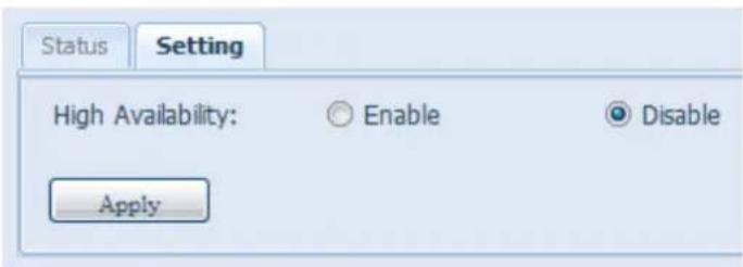
text_image
Status Setting High Availability: Enable Disable Applyiii. Choose the server role of the system, for this example, we will have this unit as 'Primary Server'. So "Primary Server" is checked.

text_image
Status Setting High Availability: Enable Disable Role: Primary Server Secondary Serveriv. Choose the "Auto Failback" option, the default is disabled. For more details about auto failback, please refer to the description below.

text_image
Auto Failback: Off On| Auto Fail Back: | In legacy Heartbeat clusters, the auto failback option would determine whether a resource would automatically fail back to its "Active" node, or remain on whatever node is serving it until that node fails, or an administrator intervenes. The possible values for auto failback were:on - enable automatic failbacksoff - disable automatic failbackWhen auto failback is off (default): After the original active server is damaged and then returned to a healthy state, the original standby server will remain active and the original active server will go into standby mode. The servers will exchange roles.When auto failback is on: After the original active server is damaged and then returned to a healthy state, the original standby server will go back into standby mode and the original active server will become active again. The servers return to their original roles.With or without auto failback, synchronization will begin immediately without a break in service when the damaged server returns. The roles described above are assumed immediately and do not need to wait for synchronization. The virtual IP will always be mapped to the current active server. |
v. Fill in the "Virtual Server" hostname information for further access need. For this example, we will use "HApm" for the virtual server hostname.
Virtual host name:
HApm
vi. Fill in the "Secondary Server" hostname information. For this example, we will use "PMS" for the secondary server hostname. Please make sure the associated Secondary server with the "PMS" host name has been setup.
Secondary host name:
PMS
vii. Fill in the "Virtual IP" information:
- Please select the network interface from the drop down list of physical connective available. It can be either on board LAN ports or additional add-in NIC, even 10G.
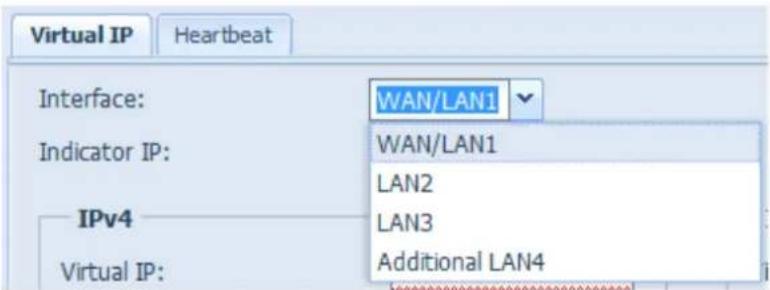
text_image
Virtual IP Interface: Indicator IP: IPv4 Virtual IP: WAN/LAN1 WAN/LAN1 LAN2 LAN3 Additional LAN4- Input "Indicate" IP address. This "indicate IP" is used for the system to ping out then check whether the system is still alive. So please input an IP address that is going to response properly.
Indicator IP:
172.16.66.243
- Filled in IP information for the "Virtual IP" and "Secondary Server IP" in either IPv4 or IPv6. For our example we chose the "WAN/LAN1" for the connection interface and virtual IP 172.16.66.87. The secondary server IP address is 172.16.66.24 has mentioned earlier.
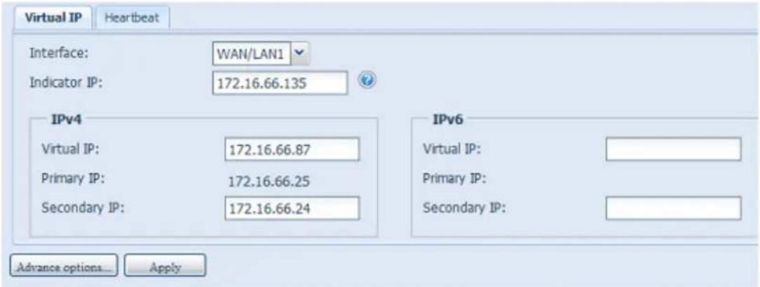
text_image
Virtual IP Heartbeat Interface: WAN/LAN1 Indicator IP: 172.16.66.135 IPv4 Virtual IP: 172.16.66.87 Primary IP: 172.16.66.25 Secondary IP: 172.16.66.24 IPv6 Virtual IP: Primary IP: Secondary IP: Advance options... Applyviii. Choose the network interface for heartbeat in between the systems. It can be selected from the drop down list, if there is additional LAN card that has been installed, such as 10G card, it can be used for the heartbeat role. After inserting the IP addresses for direct link needed in between the primary and secondary servers, default value will appear. Normally, no modifications will be required. The example here we will use the "Additional LAN4" which is a 10G NIC to be used for the heartbeat link between the primary and secondary servers.
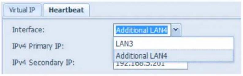
text_image
Virtual IP Heartbeat Interface: Additional LAN4 IPv4 Primary IP: LAN3 IPv4 Secondary IP: Additional LAN4 192.168.5.201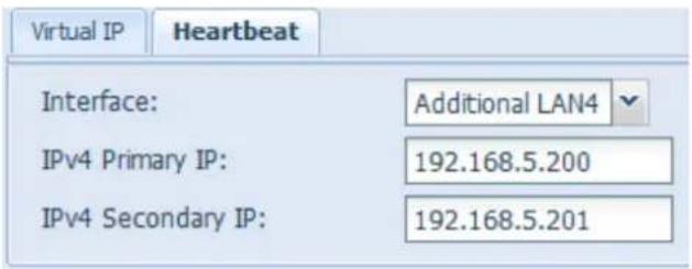
text_image
Virtual IP Heartbeat Interface: Additional LAN4 IPv4 Primary IP: 192.168.5.200 IPv4 Secondary IP: 192.168.5.201ix. Advance options can be setup by pressing the associated button.
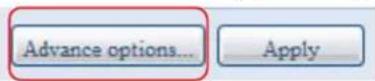
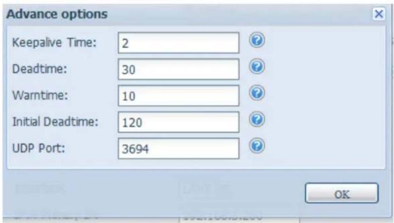
text_image
Advance options Keepalive Time: 2 Deadtime: 30 Warntime: 10 Initial Deadtime: 120 UDP Port: 3694 OK| Heart Beats Configuration | |
| Item | Description |
| Keep alive time | The keep alive directive sets the interval between heartbeat packets. It is specified according to the Heartbeat time syntax. |
| Dead time | The dead ping directive is used to specify how quickly Heartbeat should decide that a ping node in a cluster is dead. Setting this value too low will cause the system to falsely declare the ping node dead. Setting it too high will delay detection of communication failure.This feature has been replaced by the more flexible ping resource agent in Pacemaker, and should no longer be used. |
| Warning time | The warn time directive is used to specify how quickly Heartbeat should issue a "late heartbeat" warning. |
| Initial dead time | The initial dead parameter is used to set the time that it takes to declare a cluster node dead when Heartbeat is first started. This parameter generally needs to be set to a higher value, because experience suggests that it sometimes takes operating systems many seconds for their communication systems before they operate correctly. |
| UDP port | The udp port directive specifies which port Heartbeat will usefor its UDP intra-cluster communication. The default value for this parameter is UDP 694 port. |
x. Click "Apply", the Primary server will prompt the message below and wait for the "Standby" server settings to be completed.
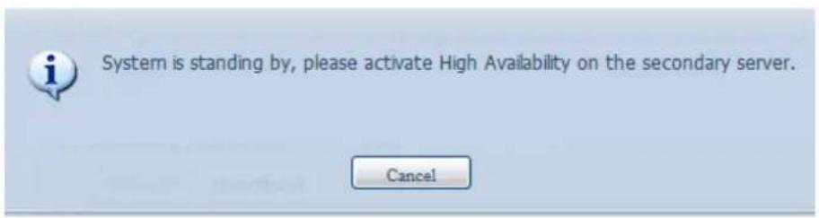
text_image
System is standing by, please activate High Availability on the secondary server. CancelSetting up the Secondary unit for HA. The secondary unit for our example is PMS (172.16.66.24):
xi. Login in to the web UI of the system 172.16.66.24 then go to "High Availability" HA configuration page under the Storage category.
xii. Click on the "Enable" radio button, the setting page will appear.
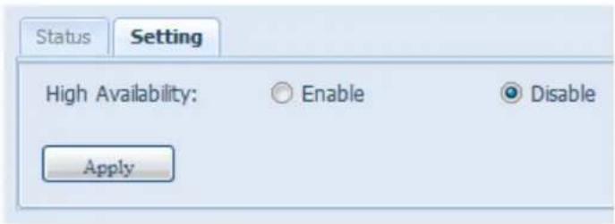
text_image
Status Setting High Availability: Enable Disable Applyxiii. Choose the server role of the system, for this example, we will have this unit set as the "Secondary Server". So "Secondary Server" is checked. After, please fill in the associated "Primary Server" IP address.
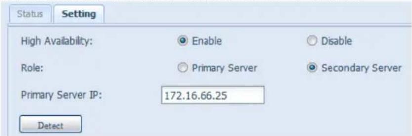
text_image
Status Setting High Availability: Enable Disable Role: Primary Server Secondary Server Primary Server IP: 172.16.66.25 Detectxiv. Click "Detect" and the Secondary unit will start to check for the Primary server status. If the Primary server has replied properly, then the message will appear as below.

text_image
Waiting for the active server to reboot... CancelPlease check the Primary Server unit. You will see an interactive message saying to reboot both "Primary" and 'Secondary" server together to complete the High Availability settings.
The last state of the Primary server is: waiting for the Secondary server as shown in the screen shot below:
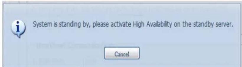
text_image
System is standing by, please activate High Availability on the standby server. CancelAfter the Secondary server has communicated with Primary Server successfully, then the state will changed to:
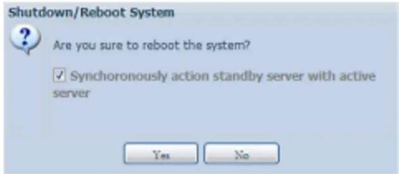
text_image
Shutdown/Reboot System Are you sure to reboot the system? ✓ Synchronously action standby server with active server Yes NoClick "Yes" to reboot both Primary and Secondary server.
If the communication has failed then you will see an error message as below.
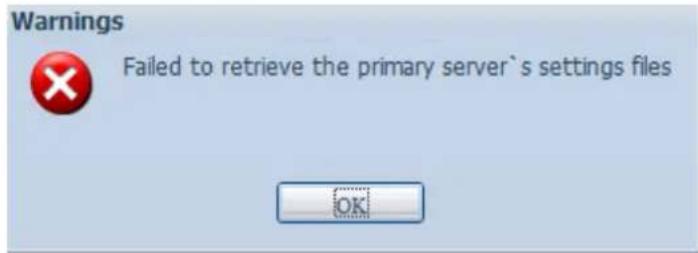
text_image
Warnings Failed to retrieve the primary server's settings files OKConditions in which the secondary server will take over to play the role as
Active:
- Primary server RAID is damaged
- Loss of the primary server's data port connection
- Primary server goes down for any other reason
When the primary server encounters the above-mentioned situations, the secondary server (PMS) will immediately take over to play the role as active. The secondary server's system log will show "HA changed to active, getting resources", and "Healthy: The RAID [HA] on system [PMS] is healthy now."
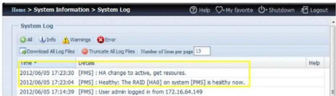
text_image
Home > System Information > System Log Help My favorite Shutdown Logout System Log All Info Warnings Error Download All Log Files Truncate All Log Files Number of lines per page 13 Time Details Help 2012/06/05 17:23:30 [PMS] : HA change to active, get resoures. 2012/06/05 17:23:04 [PMS] : Healthy: The RAID [HA0] on system [PMS] is healthy now. 2012/06/05 17:14:39 [PMS] : User admin logged in from 172.16.64.149At this time, the virtual IP address will be mapped to the PMS system because it is in an active state.
HA Ready:
After both Primary and Secondary systems has rebooted, the HA link status and the HA RAID volume can be seen from the HA status page.
Please note, it will take 1\~2 minutes to complete the primary and secondary servers' role played. If both servers are displayed as standby, please wait for the systems to synchronize with each other.

text_image
Status Setting Current role: Active HA Network Status: Primary Server Heartbeat Interface: WAN/LAN1 IP: 172.16.66.25 Secondary Server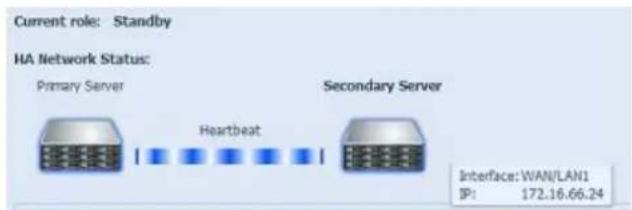
text_image
Current role: Standby HA Network Status: Primary Server Heartbeat Secondary Server Interface: WAN/LAN1 IP: 172.16.66.24From the HA Primary server "PMA (172.16.66.25)" it will denote the role of "Active" and for the "PMS (172.16.66.24)", it will show the role as Standby.
The HA RAID volume status can be found as shown in the screen shot below.
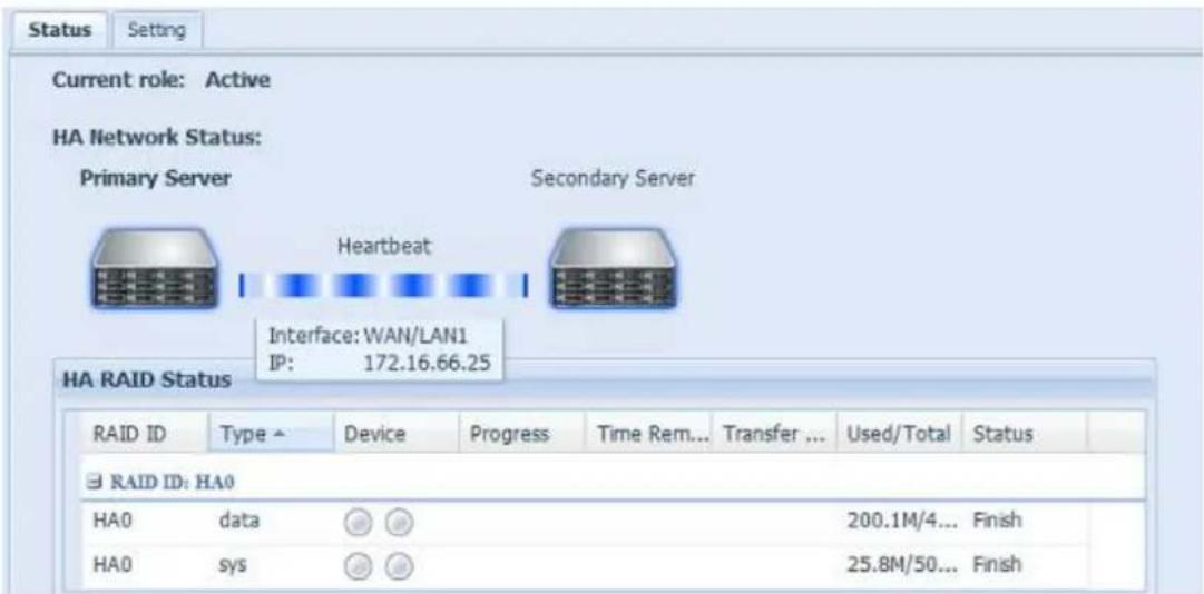
text_image
Current role: Active HA Network Status: Primary Server Secondary Server Interface: WAN/LAN1 IP: 172.16.66.25 HA RAID Status RAID ID Type Device Progress Time Rem... Transfer ... Used/Total Status RAID ID: HA0 HA0 data 200.1M/4... Finish HA0 sys 25.8M/50... FinishThe user can access this newly create HA system by its virtual IP. Using widows, the user can simply input 172.16.64.87 or HApm in the navigation bar then the available share files will be listed as below:
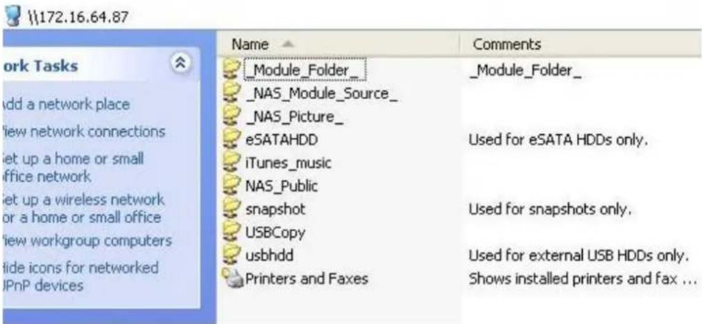
text_image
172.16.64.87 work Tasks Add a network place View network connections Set up a home or small office network Set up a wireless network or a home or small office View workgroup computers Hide icons for networked IPnP devices Name Comments _Module_Folder_ _NAS_Module_Source_ _NAS_Picture_ eSATAHDD Used for eSATA HDDs only. iTunes_music NAS_Public snapshot Used for snapshots only. USBCopy usbhdd Used for external USB HDDs only. Printers and Faxes Shows installed printers and fax ...HA Recovery:
If one of the HA member is down and need to be recovered, simply go to the RAID management page and the "HA Recovery" icon will be available.
Click on the "HA Recovery" icon, then the system will prompt a box to inquire about the Active server heartbeat link IP address. After inputting the IP address and pressing Apply, the unit will be recovered fully.
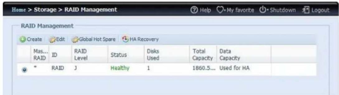
text_image
Home > Storage > RAID Management RAID Management Create Edit Global Hot Spare HA Recovery Mas... RAID ID RAID Level Status Disks Used Total Capacity Data Capacity * RAID J Healthy 1 1860.5... Used for HA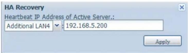
text_image
HA Recovery Heartbeat IP Address of Active Server.: Additional LAN4 : 192.168.5.200 ApplyAnother circumstance where HA recovery might be needed is when the HA button has been enable but the system detected a previously existing HA configuration. Then the screen will prompt the message box as shown below:
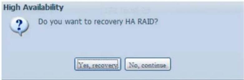
text_image
High Availability Do you want to recovery HA RAID? Yes, recovery? No, continueIf the other HA member is running smoothly, please choose "Recovery HA" to complete HA recovery. Or select "No, continue" to let both HA members has they are.
WARNING
If there are transfers in progress when the Primary server encounters problems and the Secondary server becomes active, the session will be stopped. Please contact your network administrator to determine whether or not your transfers were completed.
WARNING
When the original primary server rejoins the HA environment, it will be updated with the newer data from the secondary server to synchronize for HA. Please be aware that the data on the original primary server will be replaced by the data from the secondary server.
User and Group Authentication
The Thecus IP storage has built-in user database that allows administrators to manage user access using different group policies. From the User and Group Authentication menu, you can create, modify, and delete users, and assign them to groups that you designate.
ADS/NT Support
If you have a Windows Active Directory Server (ADS) or Windows NT server to handle the domain security in your network, you can simply enable the ADS/NT support feature; the Thecus IP storage will connect with the ADS/NT server and get all the information of the domain users and groups automatically. From the Accounts menu, choose Authentication item and the ADS/NT Support screen appears. You can change any of these items and press Apply to confirm your settings.
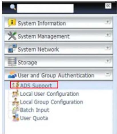
text_image
System Information System Management System Network Storage User and Group Authentication ADS Support Local User Configuration Local Group Configuration Batch Input User Quota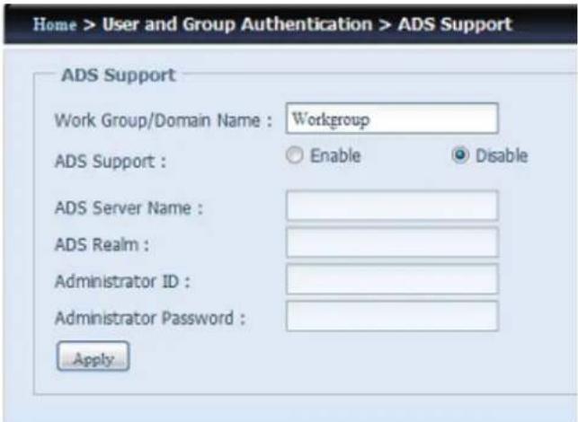
text_image
Home > User and Group Authentication > ADS Support ADS Support Work Group/Domain Name : Workgroup ADS Support : Enable Disable ADS Server Name : ADS Realm : Administrator ID : Administrator Password : ApplyA description of each item follows:
ADS/NT Support
| Item | Description |
| Work Group / Domain Name | Specifies the SMB/CIFS Work Group / ADS Domain Name (e.g. MYGROUP). |
| ADS Support | Select Disable to disable authentication through Windows Active Directory Server. |
| ADS Server Name | Specifies the ADS server name (e.g. adservername). |
| ADS Realm | Specifies the ADS realm (e.g. example.com). |
| Administrator ID | Enter the administrators ID of Windows Active Directory, which is required for Thecus IP storage to join domain. |
| Administrator Password | Enter the ADS Administrator password. |
| Apply | To save your settings. |
To join an AD domain, you can refer to the figure here and use the example below to configure the Thecus IP storage for associated filed input:
To join an AD domain, you can refer to the figure here and use the example below to configure the Thecus IP storage for associated filed input:
To join an AD domain, you can refer to the figure here and use the example below to configure the Thecus IP storage for associated filed input:
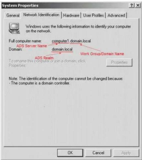
text_image
System Properties General Network Identification Hardware User Profiles Advanced Windows uses the following information to identify your computer on the network. Full computer name: computer1.domain.local ADS Server Name domain.local Domain: ADS Realm Work Group/Domain Name To rename this computer or join a domain, click Properties Properties Note: The identification of the computer cannot be changed because: - The computer is a domain controller. OK Cancel Apply| AD Domain Example | |
| Item | Information |
| Work Group / Domain Name | domain |
| ADS Support | Enable |
| ADS Server Name | Computer1 |
| ADS Realm | Domain.local |
| Administrator ID | Administrator |
| Administrator Password | ********** |


Local User Configuration
From the Accounts menu, choose the User item, and the Local User Configuration screen appears. This screen allows you to Add, Edit, and Remove local users.
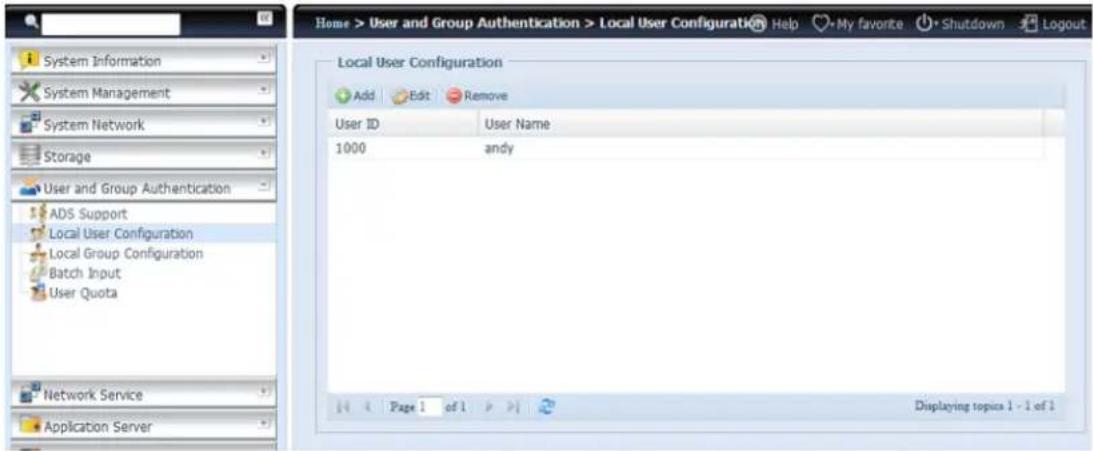
text_image
Home > User and Group Authentication > Local User Configuration Help My favorite Shutdown Logout Local User Configuration Add Edit Remove User ID User Name 1000 andy Network Service Application Server Page 1 of 1 Displaying topics 1 - 1 of 1| Local User Configuration | |
| Item | Description |
| Add | Press the Add button to add a user to the list of local users. |
| Edit | Press the Edit button to modify a local user. |
| Remove | Press the Remove button to delete a selected user from the system. |
Add Users
- Click on the Add button on Local User Configuration screen, and Local User Setting screen appears.
- On the Local User Setting screen, enter a name in the User Name box.
- Enter a User ID number or leave blank to use the system default value.
- Enter a password in the Password box and re-enter the password in the Confirm box.
- Select which group the user will belong to. Group Members is a list of groups this user belongs to. Group List is a list of groups this user does not belong to. Use the << or >> buttons to have this user join or leave a group.
- Press the Apply button and the user is created.
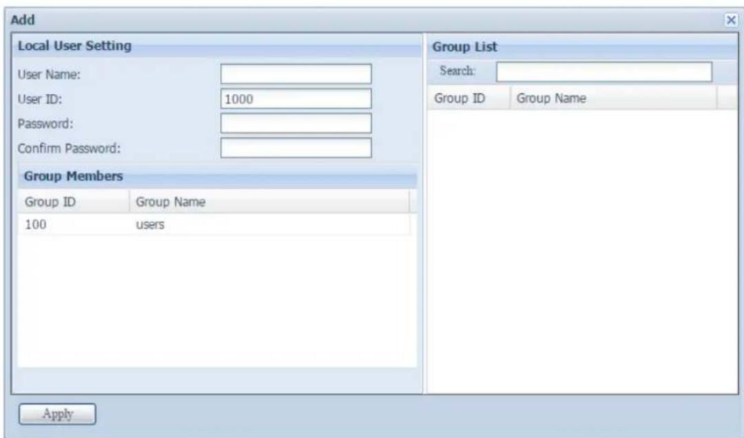
text_image
Add Local User Setting User Name: User ID: 1000 Password: Confirm Password: Group Members Group ID Group Name 100 users Group List Search: Group ID Group Name ApplyNOTE
All users are automatically assigned to the 'users' group.
Edit Users
- Select an existing user from the Local User Configuration screen.
- Click on the Edit button, and the Local User Setting screen appears.
- From here, you can enter a new password and re-enter to confirm, or use the << or >> buttons to have this user join or leave a group. Click the Apply button to save your changes.
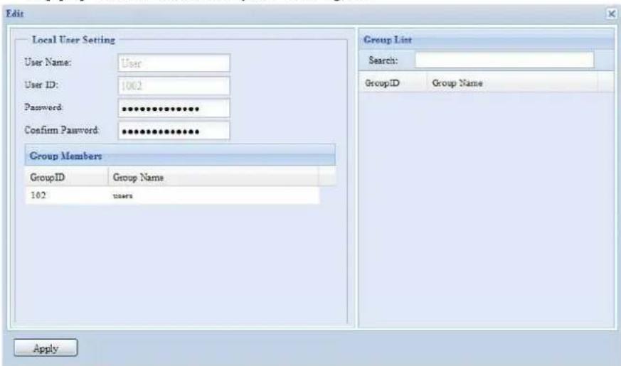
text_image
Edit Local User Setting User Name: User User ID: 1002 Password: ************ Confirm Password: ************ Group Members GroupID Group Name 102 users Group List Search: GroupID Group Name ApplyRemove Users
-
Select an existing user from the Local User Configuration screen.
-
Click on Remove button and the user is deleted from the system.
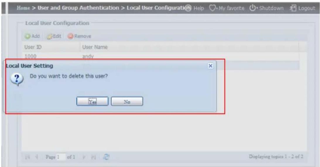
text_image
Home > User and Group Authentication > Local User Configuration Help My favorite Shutdown Logout Local User Configuration Add Edit Remove User ID User Name 1000 andy Local User Setting Do you want to delete this user? Yes No Page 1 of 1 Displaying topics 1 - 2 of 2Local Group Configuration
From the Accounts menu, choose the Group item, and the Local Group Configuration screen appears. This screen allows you to Add, Edit, and Remove local groups.
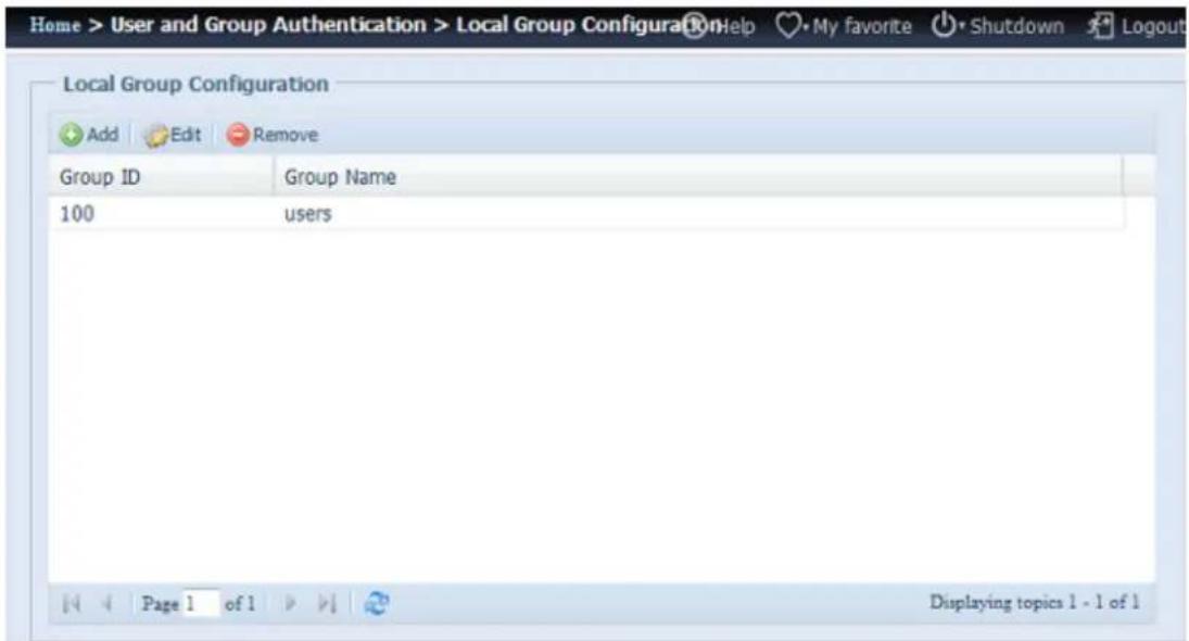
text_image
Home > User and Group Authentication > Local Group Configurati Logout Local Group Configuration Add Edit Remove Group ID Group Name 100 users Page 1 of 1 Displaying topics 1 - 1 of 1| Local Group Configuration | |
| Item | Description |
| Add | Press the Add button to add a user to the list of local groups. |
| Edit | Press the Edit button to modify a selected group from the system |
| Remove | Press the Remove button to delete a selected group from the system. |
Add Groups
- On the Local Group Configuration screen, click on the Add button.
- The Local Group Setting screen appears.
-
Enter a Group Name.
-
Enter a Group ID number. If left blank, the system will automatically assign one.
-
Select users to be in this group from the Users List by adding them to the Members List using the << button.
-
Click the Apply button to save your changes.
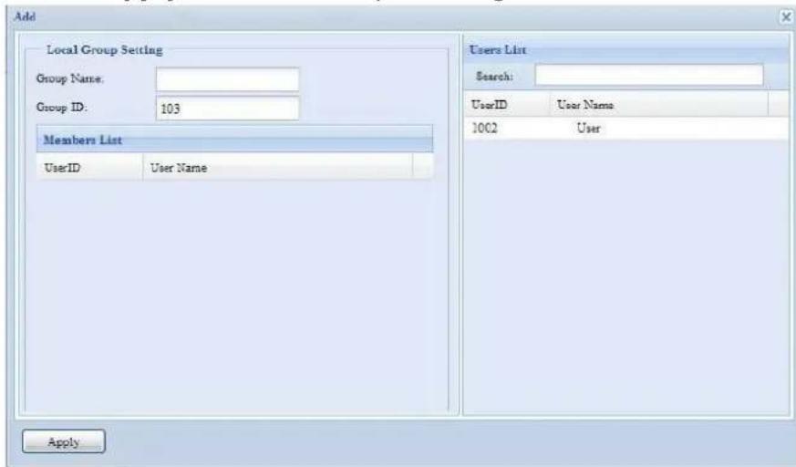
text_image
Add Local Group Setting Group Name: Group ID: 103 Members List UserID User Name Users List Search: UserID User Name 1002 User ApplyEdit Groups
-
On the Local Group Configuration screen, select a group name from the list.
-
Press the Edit button to modify the members in a group.
-
To add a user into a group, select the user from the Users List, and press the << button to move the user into the Members List.
-
To remove a user from a group, select the user from Members List, and press the >> button.
-
Click the Apply button to save your changes.
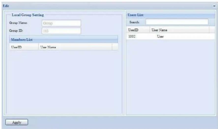
text_image
Edit Local Group Setting Group Name: Group Group ID: 103 Members List UserID User Name Users List Search: UserID User Name 1002 User ApplyRemove Groups
-
On the Local Group Configuration screen, select a group name from the list.
-
Press Remove to delete the group from the system.
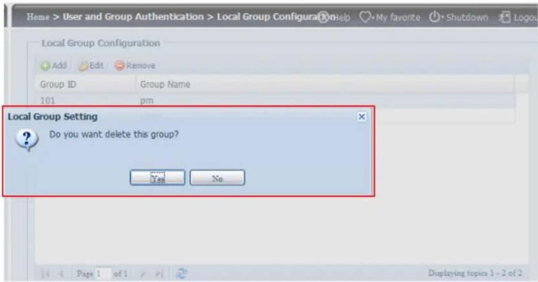
text_image
Home > User and Group Authentication > Local Group Configuration Help My favorite ⬤ Shutdown Logou Local Group Configuration Add Edit Remove Group ID Group Name 101 pm Local Group Setting Do you want delete this group? Yes No Page 1 of 1 Displaying topics 1 - 2 of 2Batch Users and Groups Creation
The Thecus IP storage can also add users and groups in batch mode. This enables you to conveniently add numerous users and groups automatically by importing a simple comma-separated plain text (*.txt) file.
From the Accounts menu, click Batch Input and the Batch User and Group Cration dialogue will appear. To import your list of users and groups, follow these steps:
- Click the Browse icon to locate your comma-separated text file. The information in the text file should follow this format:
[USERNAME], [PASSWORD], [GROUP]
- Click Open.
- Click Import to begin the user list import.
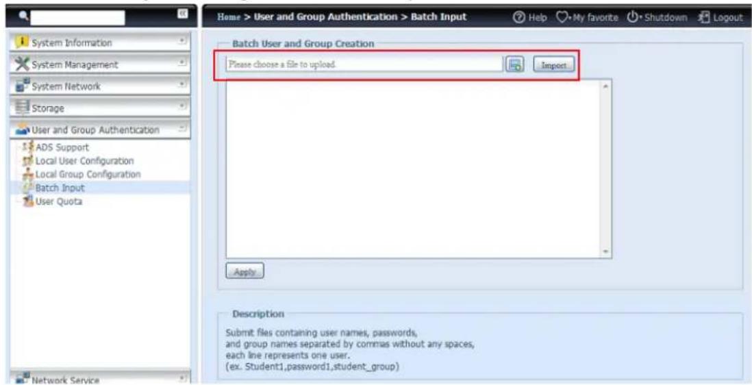
text_image
Home > User and Group Authentication > Batch Input System Information System Management System Network Storage User and Group Authentication ADS Support Local User Configuration Local Group Configuration Batch Input User Quota Network Service Batch User and Group Creation Please choose a file to upload. Import Apply Description Submit files containing user names, passwords, and group names separated by commas without any spaces, each line represents one user. (ex. Student1,password1,student_group)User Quota
The Thecus IP storage support local or AD users with storage quota limitations in each RAID volume of the system. To enable this function, simply click "Enable", then apply.

text_image
User Quota Quota Support User Quota: Enable Disable ApplyNext, each user can be setup a global storage quota size for each RAID volume. Simply click on "Quota Size" for each user and input the desired capacity. After the setup is complete, please click on "Apply" to activate the user quota size.
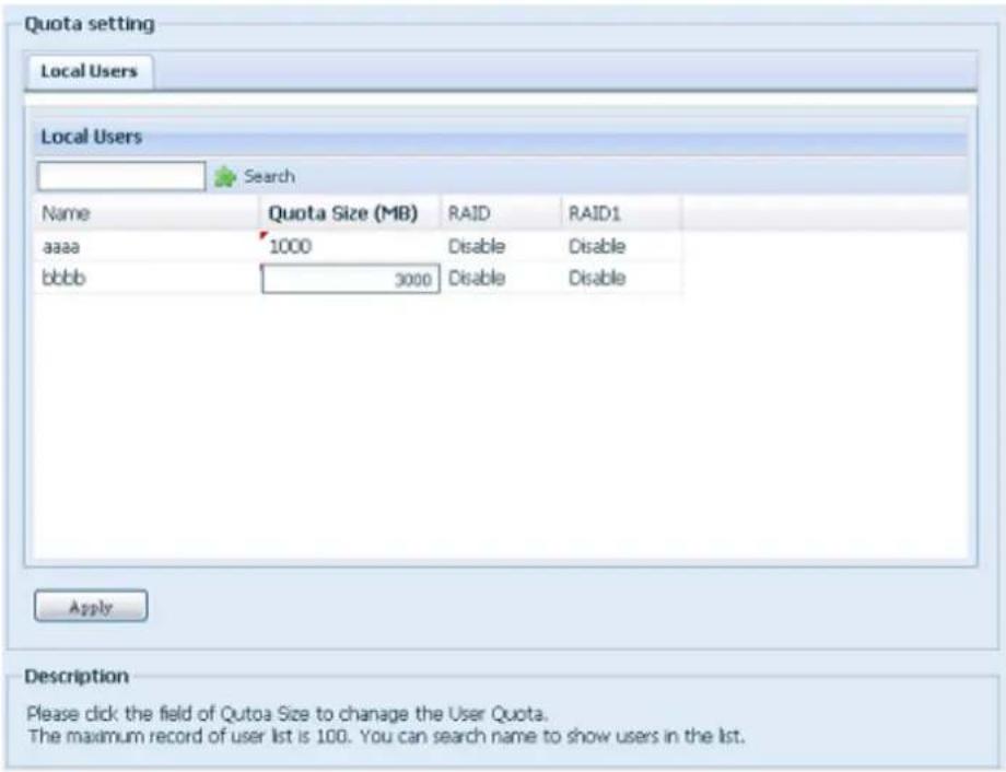
text_image
Quota setting Local Users Local Users Search Name Quota Size (MB) RAID RAID1 aaaa 1000 Disable Disable bbbb 3000 Disable Disable Apply Description Please click the field of Qutoa Size to change the User Quota. The maximum record of user list is 100. You can search name to show users in the list.User and Group Backup
The user and group backup feature allow system users and groups to be backed up to another location and be restored if needed.
Please note, when restoring previous backup users and groups, the current users and groups list will be replaced from this restore file's contents.
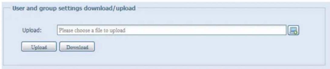
text_image
User and group settings download/upload Upload: Please choose a file to upload Upload DownloadLDAP Support
The LDAP is the other way to authenticate login users who has joined LDAP server, fill in the LDAP server information and get LDAP authentication started. Please make sure that the LDAP server has a Samba sam and a POSIX ObjectClass account.
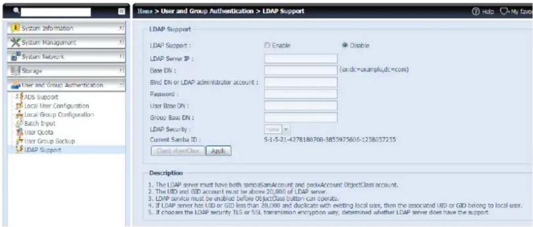
text_image
Home > User and Group Authentication > LDAP Support System Information System Management System Network Storage User and Group Authentication ADS Support Local User Configuration Local Group Configuration Batch Input User Quota User Group Backup LDAP Support LDAP Support : Enable Disable LDAP Server IP : Base DN : (a:dc=example,dc=com) Blind DN or LDAP administrator account : Password : User Base DN : Group Base DN : LDAP Security : Current Samba ID : S-1-5-21-4278180700-3855975606-1258057255 Check objectClass Apply Description 1. The LDAP server must have both sambaSamAccount and posixAccount ObjectClass account. 2. The UID and GID account must be above 20,000 of LDAP server. 3. LDAP service must be enabled before ObjectClass button can operate. 4. If LDAP server has UID or GID less than 20,000 and duplicate with existing local user, then the associated UID or GID belong to local user. 5. If chooses the LDAP security TLS or SSL transmission encryption way, determined whether LDAP server does have the support.A description of each item follows:
| LDAP Support | |
| Item | Description |
| LDAP Support | Enable or Disable LDAP service. |
| LDAP Server IP | Input LDAP server IP address. |
| Base DN | Input base domain information ex. dc=tuned, dc=com, dc=tw |
| Bind DN or LDAP administrator account | Input Administrator's name. |
| Password | Input Administrator's password. |
| User Base DN | Input organization unit information where users are stored. |
| Group Base DN | Input organization unit information where groups are stored. |
| LDAP Security | Choose the LDAP security type from drop-down list. |
| Current Samba ID | Display the current Samba ID. |
| Apply | Click Apply to save your changes. |
| Check ObjectClass | Click this checkbox to ensure LDAP server has a Samba sam and a POSIX account or it may not work properly for LDAP client authentication. |
Network Service
Use the Network Service menu to make network service support settings.
Samba / CIFS
There are options allow Admin to Enable/Disable to operate Thecus IP storage associated with Samba / CIFS protocol. With the option changed, it will need to reboot system to activate.
Samba/CIFS
| Samba Service: | Enable | Disable |
| File Access Cache: | Enable | Disable |
| Samba Anonymous Login Authentication: | Enable | Disable |
| Samba Native Mode: | Yes (Native Mode) | No (Compatible Mode) |
| Allow Trusted Domains: | Yes | No |
| Block Size: | 4096 | 1024 |
| Server Signing: | Auto | Mandatory Disable |
| Support Policy for LDAP: | Sign Seal | Plain |
| NT ACL Support: | Enable | Disable |
| Allocated buffering size: | Enable | Disable |
Samba Service
Used for letting the operating system of UNIX series and SMB/CIFS of Microsoft Windows operating system (Server Message Block / Common Internet File System). Do the link in network protocol. Enable or Disable SMB/CIFS protocol for Windows, Apple, Unix drive mapping.
NOTE
- In some environments, due to security concerns, you may wish to disable SMB/CIFS as a precaution against computer viruses.
File Access Cache
File Access Cache is default Enable. This option will help to increase the performance while single client access share folder in writing under SMB/CIFS protocol.
Samba Anonymous Login Authentication
To enable this option, no matter there is share folder has been created in public access. The user account and password is needed from system to access under SMB/CIFS protocol. On the other hand, no more anonymous login is allowed.
Samba Native mode
The Thecus IP storage is supported Samba mode options. In the ADS environment with "Native" mode selected then Thecus IP storage is capable to become local master position.
Optimize Block Size
This function controls the behavior of Samba when reporting available disk space. This function was added to allow advanced administrators to increase block size to increase write performance without re-compiling the code.
Server Signing
This is setting while Samba server has been used in US of FDCC. If the system has used only in Windows environment choose "Mandatory" otherwise "Auto".
Samba/CIFS Options for Mac OS X
UNIX Extensions:
Enable
Disable
UNIX Extension
The default is enable for Samba usage, with situation using Mac OSX with smb connection may have permission issue. When it happened, please setup "UNIX Extension" disable to get issue solved.
Samba/CIFS Options for Recycle Bin
Samba Recycle Bin:
Enable
Disable
Recycle bin contents are deleted after:

days
(Set as 0 for manual deletion only)
Recycle Bin Folder Display:
Enable
Disable
Recycle Bin Max File Size:

GB
(Set as 0 for unrestricted)
Samba Recycle Bin
The Thecus IP storage is supported recycle bin via SMB/CIFS protocol.
Simply enable the "Recycle Bin" function and "Recycle Folder Display" then all of deleted files/folders will reside in the "_NAS_Recycle_(Associated RDID Volume)" share folder.
Samba/CIFS Options for Recycle Bin
Samba Recycle Bin:

Disable
Recycle bin contents are deleted after:

days
(Set as 0 for manual deletion only)
Recycle Bin Folder Display:

Disable
Recycle Bin Max File Size:

GB
(Set as 0 for unrestricted)
For example, the system has created 2 RAID volumes with ID "RAIDpm" and 'RAID". Then it will have 2 recycle bin folder appear as "_NAS_Recycle_RAID" and "_NAS_Recycle_RAIDpm".
| Mas... RAID | ID | RAID Level | File System | Status | |
| RAIDpm | J | EXT4 | Healthy | ||
| * | RAID | J | XFS | Healthy |
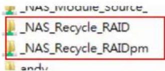
text_image
_NAS_Module_source_ _NAS_Recycle_RAID _NAS_Recycle_RAIDpm andyThere are 2 more setting could help to manage the recycle bin for deleted folders/files.
- Setup the "Day" to remove deleted folders/files which has resided in recycle bin permanently. Left default value "0" if desired to clean up recycle bin manually.
- Setup the "Size" for recycle bin to allow deleted folders/files can store. Left default value "0" with no limitation.
NOTE
- The deleted files/folders which have resided in recycle bin will keep its permission. On the other hand, only the admin and owner can view/read/write these folders/files.
- If deleted single file size is large than 2GB then it won't reside in the recycle bin but erase permanently.
AFP (Apple Network Setup)
From the Network Service menu, choose the AFP item, and the AFP Support screen appears. This screen displays the configuration items for the Apple Filing Protocol. You can change any of these items and press Apply to confirm your settings.
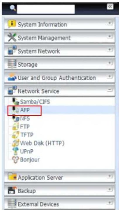
text_image
System Information System Management System Network Storage User and Group Authentication Network Service Samba/CIFS AFP NFS FTP TFTP Web Disk (HTTP) UPnP Bonjour Application Server Backup External Devices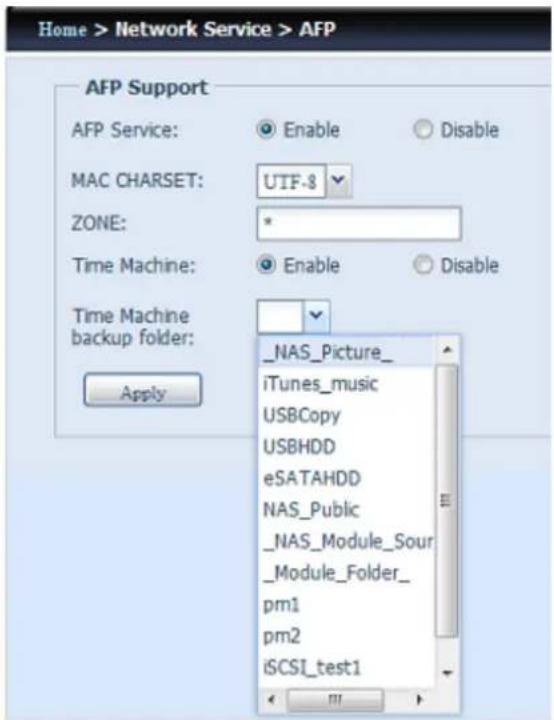
text_image
Home > Network Service > AFP AFP Support AFP Service: Enable Disable MAC CHARSET: UTF-8 ZONE: * Time Machine: Enable Disable Time Machine backup folder: Apply _NAS_Picture_ iTunes_music USBCopy USBHDD eSATAHDD NAS_Public _NAS_Module_Sour _Module_Folder_ pm1 pm2 iSCSI_test1A description of each item follows:
| Apple Network Configuration | |
| Item | Description |
| AFP Server | Enable or disable Apple File Service to use the Thecus IP storage with MAC OS-based systems. |
| MAC CHARSET | Specifies the code page from the drop down list. |
| Zone | Specifies Zone for Applet Talk service.If your AppleTalk network uses extended networks and is assigned with multiple zones, assign a zone name to the Thecus IP storage. If you do not want to assign a network zone, enter an asterisk (*) to use the default setting. |
| Time Machine | Click the enable checked box if you would like your MAC system t use the Thecus IP storage as MAC time machine backup. |
| Time Machine backup folder | Select from the drop down list to designate the folder for time machine backup destination. |
NFS Setup
From the Network Service menu, choose the NFS item, and the NFS Support screen appears. The Thecus IP storage can act as an NFS server, enabling users to download and upload files with their favorite NFS clients. Press Apply to confirm your settings.
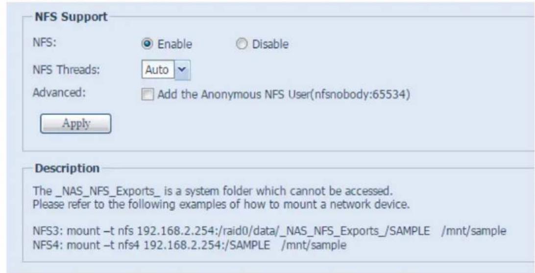
text_image
NFS Support NFS: Enable Disable NFS Threads: Auto Advanced: Add the Anonymous NFS User(nfsnobody:65534) Apply Description The _NAS_NFS_Exports_ is a system folder which cannot be accessed. Please refer to the following examples of how to mount a network device. NFS3: mount -t nfs 192.168.2.254:/raid0/data/_NAS_NFS_Exports_/SAMPLE /mnt/sample NFS4: mount -t nfs4 192.168.2.254:/SAMPLE /mnt/sampleA description of each item follows:
| NFS Server Setting | |
| Item | Description |
| NFS | Enable or Disable NFS support. |
| NFS Threads | Choose the number of NFS threads. |
| Advanced | Checked to add the Anonymous NFS User. |
| Apply | Click Apply to save your changes. |
FTP
The Thecus IP storage can act as an FTP server, enabling users to download and upload files with their favorite FTP programs. From the Network Service menu, choose the FTP item, and the FTP screen appears. You can change any of these items and press Apply to confirm your settings.
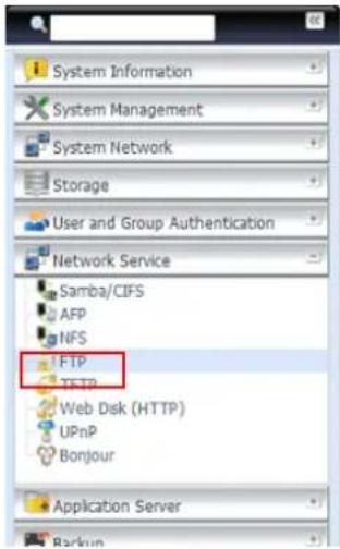
text_image
System Information System Management System Network Storage User and Group Authentication Network Service Samba/CIFS AFP NFS FTP TFTP Web Disk (HTTP) UPnP Bonjour Application Server Backup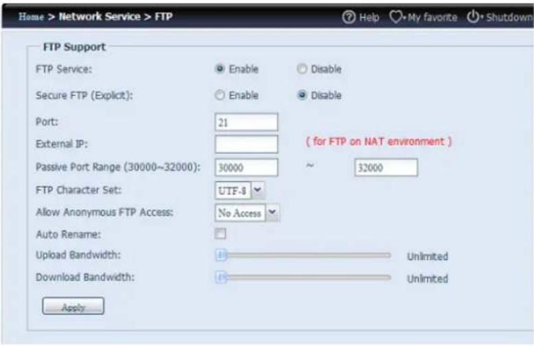
text_image
Home > Network Service > FTP FTP Support FTP Service: Enable Disable Secure FTP (Explicit): Enable Disable Port: 21 External IP: Passive Port Range (30000~32000): 30000 ~ 32000 FTP Character Set: UTF-8 Allow Anonymous FTP Access: No Access Auto Rename: Upload Bandwidth: Unlimited Download Bandwidth: Unlimited ApplyA description of each item follows:
| FTP | |
| Item | Description |
| FTP | Enables FTP Service on the Thecus IP storage. |
| Security FTP | Enable or disable Security FTP, be sure the client FTP software has also security FTP setting enabled. |
| Port | Specifies the port number of an incoming connection on a non-standard port. |
| External IP | Input the public IP address of the router when the Thecus secure FTP server has been enabled. This can help to respond to the ftp client with proper communication information. |
| Passive Port Range (30000-32000) | Limited port range for the FTP server to use. |
| FTP ENCODE | If your FTP client or operating system does not support Unicode (e.g. Windows® 95/98/ME or MAC OS9/8), select the same encoding as your OS here in order to properly view the files and directories on the server. Available options are BIG5, HZ, GB2312, GB18030, ISO, EUC-JP, SHIFT-JIS and UTF-8. |
| Allow Anonymous FTP Access | Upload/Download: Allow anonymous FTP users to upload or download files to/from public folders.Download: Allow anonymous FTP users to download files from public folders.No access: Block anonymous FTP user access. |
| Auto Rename | If checked, the system will automatically rename files that are uploaded with a duplicate file name. The renaming scheme is [filename].#, where # represents an integer. |
| Upload Bandwidth | You may set the maximum bandwidth allocated for file uploads. Selections include Unlimited, 1 ~ 32 MB/s. |
| Download Bandwidth | You may set the maximum bandwidth allocated for file downloads. Selections include Unlimited, 1 ~ 32 MB/s. |
To access the share folder on the Thecus IP storage, use the appropriate user login and password set up on the Users page. Access control to each share folder is set up on the ACL page (Storage Management > Share Folder > ACL).
TFTP
Thecus IP storage can act as a TFTP server, enabling users to download and upload files with their favorite TFTP programs. From the Network Service menu, choose the TFTP item, and the TFTP screen appears. You can change any of these items and press Apply to confirm your settings.
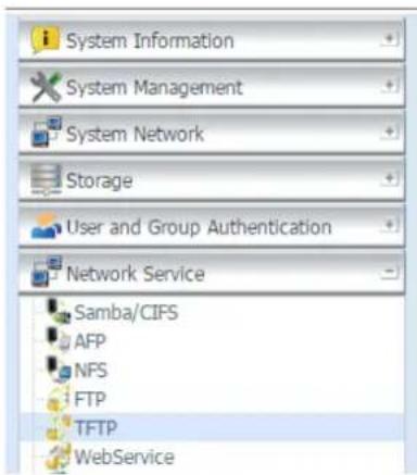
text_image
System Information System Management System Network Storage User and Group Authentication Network Service Samba/CIFS AFP NFS FTP TFTP WebService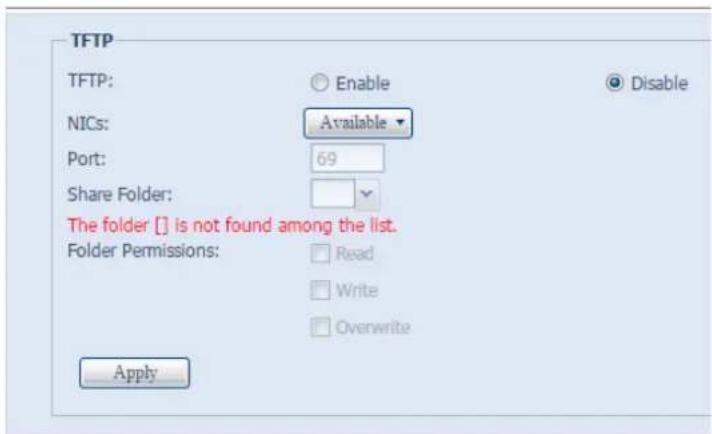
text_image
TFTP TFTP: Enable Disable NICs: Available Port: 69 Share Folder: The folder [] is not found among the list. Folder Permissions: Read Write Overwrite ApplyA description of each item follows:
| TFTP | |
| Item | Description |
| TFTP | Enables TFTP Service on the Thecus IP storage. |
| NICs | Choose NICs to enable port use |
| Port | Specifies the port number of an incoming connection on a non-standard port. |
| Share Folder | Select the file stored folder, it cannot be empty. |
| Folder Permission | Select the folder permission |
WebService
From the Network Service menu, choose the WebService item, and the WebService Support screen appears. This screen displays the service support parameters of the system. You can change any of these items and press Apply to confirm your settings.
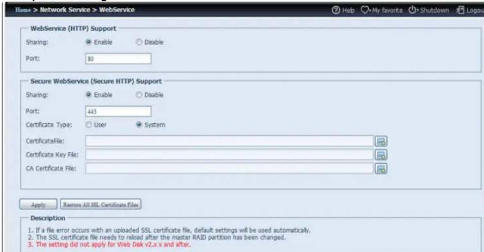
text_image
Home > Network Service > WebService Help My favorite Shutdown Logout WebService (HTTP) Support Sharing: Enable Disable Port: 50 Secure WebService (Secure HTTP) Support Sharing: Enable Disable Port: 443 Certificate Type: User System CertificateFile: Certificate Key File: CA Certificate File: Apply Restore All SSL Certificate Files Description 1. If a file error occurs with an uploaded SSL certificate file, default settings will be used automatically. 2. The SSL certificate file needs to reload after the master RAID partition has been changed. 3. The setting did not apply for Web Disk v2.x x and after.A description of each item follows:
| Web Service | |
| Item | Description |
| WebService (HTTP) Support | Enable or disable WebDisk support. Enter the port number if this option is enabled. The port number is default 80. |
| Secure WebService (Secure HTTP) Support | Enable or disable secure WebDisk support. Enter the port if this option is enabled. |
| Certificate File | Upload Certificate File if choose Certificate type "User". |
| Certificate Key File | Upload Certificate Key File if choose Certificate type "User". |
| CA Certificate File | Upload CA Certificate File if choose Certificate type "User". |
| Restore All SSL Certificate Files | Click to set back to default certification details. |
| Apply | Click "Apply" to confirm the changes. |
NOTE
- Disable HTTP support and Enable Secure HTTP support to guarantee secure access.
UPnP
This device supports UPnP Media server, which allows users to play media files with UPnP client (ex. DMA devices). Enable or disable Universal Plug and Play protocol. UPnP helps to find the IP address of Thecus IP storage.
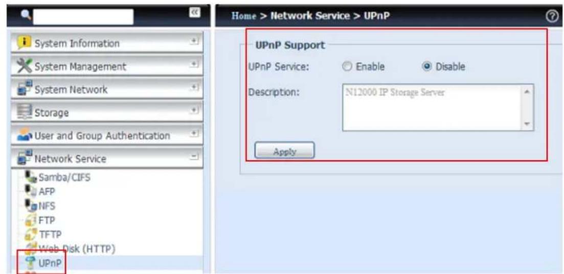
text_image
Home > Network Service > UPnP UPnP Support UPnP Service: Enable Disable Description: N12000 IP Storage Server ApplyBonjour Setting
Bonjour, is Apple Inc.'s trade name for its implementation of Zeroconf, a service discovery protocol. Bonjour locates devices such as printers, as well as other computers, and the services that those devices offer on a local network using multicast Domain Name System service records. This definitive guide walks you through Bonjour zero-configuration networking with a complete description of the protocols and technologies used to create Bonjour enabled applications and devices.
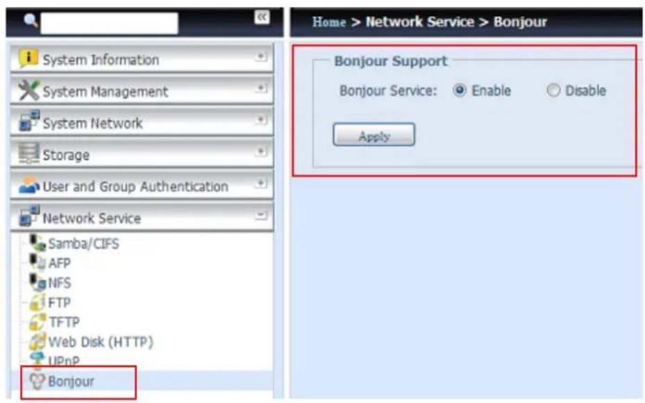
text_image
System Information System Management System Network Storage User and Group Authentication Network Service Samba/CIFS AFP NFS FTP TFTP Web Disk (HTTP) UPnP Bonjour Home > Network Service > Bonjour Bonjour Support Bonjour Service: Enable Disable ApplySSH
The device is now SSH protocol supported. It allows user to use SSH and have console to manipulate as needed. The SSH default login user name is "root" with full privilege and password is admin's password. The default admin password is "admin" so once the admin password has changed then SSH login need to change the password too.
A description for each item as following:
| SSH | |
| Item | Description |
| SSH Service | Enable or disable SSH service. |
| Port | The port number is default 22. |
| SFTP | Enable or disable SFTP protocol under SSH service. |
| Apply | Click "Apply" to confirm the changes. |
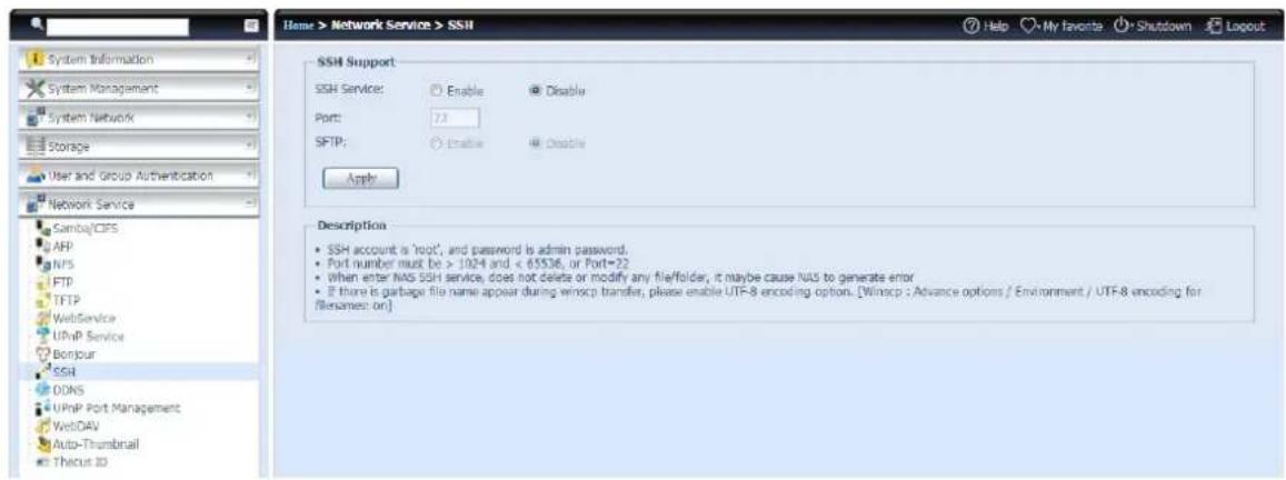
text_image
Home > Network Service > SSH SSH Support SSH Service: Enable Disable Port: 7.3 SFTP: Enable Enable Apply Description • SSH account is 'root', and password is admin password. • Port number must be > 1024 and < 65536, or Port=22 • When enter NAS SSH service, does not delete or modify any file/folder, it maybe cause NAS to generate error • If there is garbage file name appear during winscp transfer, please enable UTF-8 encoding option. [Winscp : Advance options / Environment / UTF-8 encoding for files named on]DDNS
To set up a server on the Internet and enable the users to connect to it easily, a fixed and easy-to remember host name is often required. However, if the ISP provides only dynamic IP address, the IP address of the server will change from time to time and is difficult to recall. You can enable the DDNS service to solve the problem.
After enabling the DDNS service of the NAS, whenever the NAS restarts or the IP address is changed, the NAS will notify the DDNS provider immediately to record the new IP address. When the user tries to connect to the NAS by the host name, the DDNS will transfer the recorded IP address to the user.
The NAS supports the DDNS providers:
DyDNS.org(Dynamic DNS), DyDNS.org(Custom DNS), DyDNS.org(Static DNS), www.zoneedit.com, www.no-ip.com.
A description for each item as following:
| DDNS | |
| Item | Description |
| DDNS Service | Enable or disable DDNS service. |
| Register | Choose the service provider from the drop down list |
| User name | Input user name with DDNS registry. |
| Password | Input password with DDNS registry. |
| Domain name | Input domain name with DDNS registry. |
| Apply | Click "Apply" to confirm the changes. |
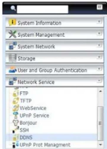
text_image
System Information System Management System Network Storage User and Group Authentication Network Service FTP TFTP WebService UPnP Service Bonjour SSH DDNS UPnP Prot Management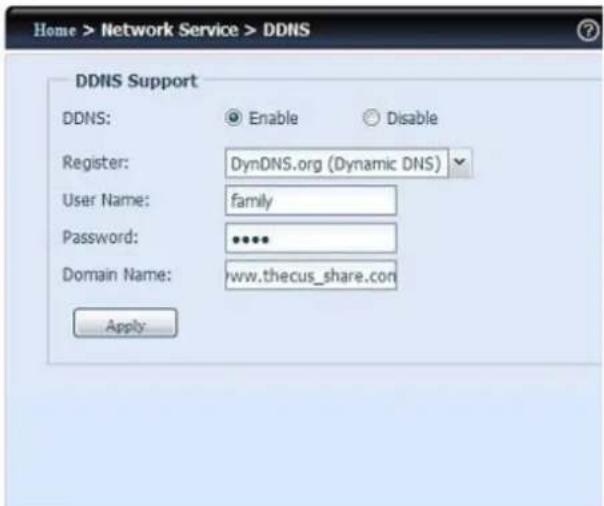
text_image
Home > Network Service > DDNS DDNS Support DDNS: Enable Disable Register: DynDNS.org (Dynamic DNS) User Name: family Password: ***** Domain Name: www.thecus_share.com ApplyUPnP Port Management
One of the most convent way to allow users to access required services such as FTP, SSH, web disk and http etc. from Internet environment is setting UPnP port management.
To set up this UPnP port forwarding feature, please be sure that the router has "UPnP Service" Enabled. The following is an example from one of the router manufacture with UPnP Configuration page.
UPnP Configuration
UPnP Service

Enable

Disable
Clear port forwards at startup

Enable

Disable
Save
Apply Settings
Cancel Changes
After the router has enabled "UPnP Service" then you will have information come from associated router to UPnP port management as shown in the screen shot below.
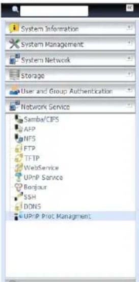
text_image
System Information System Management System Network Storage User and Group Authentication Network Service Samba/CIFS AFP NFS FTP TFTP WebService UPnP Service Borgour SSH DDNS UPnP Plot Management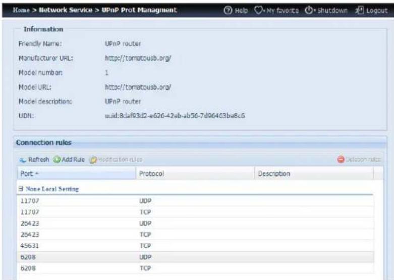
text_image
Home > Network Service > UPnP Prot Management Help My favorite Shutdown Logout Information Friendly Name: UPnP router Manufacturer URL: http://tomatousb.org/ Model number: 1 Model URL: http://tomatousb.org/ Model description: UPnP router UDN: uid:8daf93d2-e626-42eb-ab56-7d96463ba8c6 Connection rules Refresh Add Rule Modification rules Port Protocol Description None Local Setting 11707 UDP 11707 TCP 25423 UDP 25423 TCP 45631 TCP 6208 UDP 6208 TCPAnd click "Add Rule" to add more port mapping from Internet to access desired services or press "Refresh" to get most updated list.
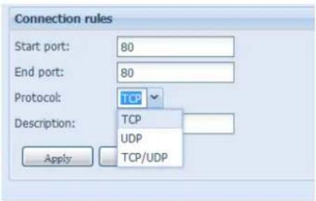
text_image
Connection rules Start port: 80 End port: 80 Protocol: TCP Description: TCP UDP TCP/UDP ApplyA description for each item as following:
| UPnP Port Management | |
| Item | Description |
| Start port | Specific port number starts with. |
| End port | Specific port number ended |
| Protocol | Choose the protocol for port forwarding needed. |
| Description | Specific the port services if applicable. |
| Apply | Click "Apply" to confirm the changes. |
| Cancel | Click "Cancel" to abort the changes |
WARNING
Some of the routers do not allow the input of port number below 1024. So it may have resulted "setting fails".
WebDAV
The WebDAV is an extended protocol of http(s) which allows remote access to your NAS system.
To begin using WebDAV and WebDAV SSL, simply click enable and provide the port number. The default port number is 9800, under normal circumstances this will not need to be changed.
WebDAV Support
WebDAV:
Enable
Disable
Port:
9800
WebDAV SSL:
Enable
Disable
Port:
9802
Browser View:
Enable
Disable
Apply
Description
-Port number must be > 1024 and < 65536
- Please set WebDAV ACL at [Share Folder] function
- 「Browser View」 provide valid user view files on browsers
| WebDAV Configuration | |
| Item | Description |
| WebDAV Service | Press the Enable button to activate WebDAV service and specify the port number if it needs to change from the default value.P.S. Port number is limited to greater than 1024 and less than 65536 |
| WebDAV SSL Service | Press the Enable button to activate WebDAV SSL service and specify the port number if it needs to be changed from the default value.P.S. The ort number is limited to greater than 1024 and less than 65536 |
| Browser View | Press the Enable button and viewing the share folder list through the browser will be allowed |
| Apply | Click "Apply" to confirm the changes. |
Auto-Thumbnail
The auto thumbnail is a function on the GUI that can be used with the Thecus T-OnTheGo mobile application. It helps to resize a photo while when it is on written the NAS system. Enable this service allows you to speed up photo viewing on your Mobile device.
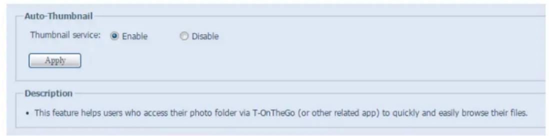
text_image
Auto-Thumbnail Thumbnail service: ○ Enable ○ Disable Apply Description • This feature helps users who access their photo folder via T-OnTheGo (or other related app) to quickly and easily browse their files.| Auto Thumbnail Configuration | |
| Item | Description |
| Auto Thumbnail Service | Press the Enable button to activate the auto thumbnail service. |
| Apply | Click "Apply" to confirm the changes. |
Thecus ID
Creating a Thecus ID will give you full access to all that Thecus has to offer. After creating a Thecus ID, you'll receive a free* DDNS (i.e"yourname.thecuslink.com".) You can use your DDNS to easily access your NAS, make use of the mobile T-OnTheGo™ app, and share links to files with your friends. In the future, free cloud backup of your NAS configuration file will also be provided.
From here, it will display the current Thecus ID and DDNS information for the associated Thecus NAS system and also the port connection status. You can click logout if remote access is no longer needed.
If your Thecus NAS system is not currently logged in, or if DDNS has not yet been applied, then it can be done here.
- Login Thecus NAS system:
Simply input your existing Thecus ID and DDNS for this Thecus NAS then press Apply.
- Create free DDNS for your Thecus NAS:
With registered Thecus ID, you could create DDNS for your Thecus NAS by fill in valid Thecus ID and password. Then input desired DDNS name to complete DDNS creation.
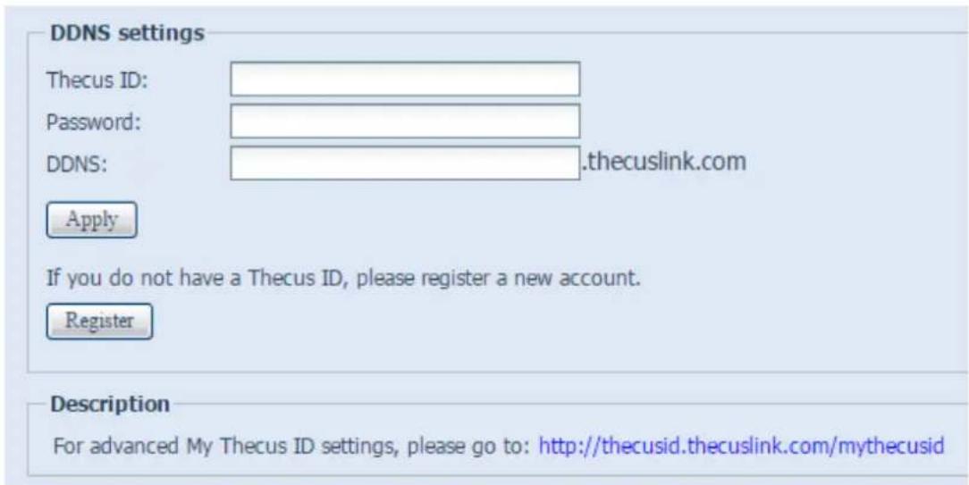
text_image
DDNS settings Thecus ID: Password: DDNS: .thecuslink.com Apply If you do not have a Thecus ID, please register a new account. Register Description For advanced My Thecus ID settings, please go to: http://thecusid.thecuslink.com/mythecusidIf you don't have a Thecus ID, click "Register" and the screen below will appear. Please fill in the required information and click Apply.
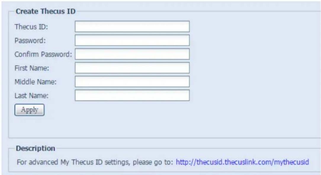
text_image
Create Thecus ID Thecus ID: Password: Confirm Password: First Name: Middle Name: Last Name: Apply Description For advanced My Thecus ID settings, please go to: http://thecusid.thecuslink.com/mythecusid| Register Thecus ID | |
| Item | Description |
| Thecus ID | Input a valid email address. It will require confirmation to activate your Thecus ID. |
| Password | Input the password for your Thecus ID |
| Confirm Password | Re-input the password for your Thecus ID. |
| First Name | Input your First name |
| Middle Name | Input your Middle name |
| Last Name | Input your Last name |
| Apply | ClickApplyto save your changes. |
Once your ThecusID has been registered, you will be given access to a webpage providing more information (i.e. connection test, re-send password, etc.).
http://thecusid.thecuslink.com/mythecusid/index.php

text_image
Therus Creator in StorageMy Thecus® ID
Home
Login
Forgot Password
Resend Activation Email
Thank you for using Thecus® NAS.
What is Thecus® ID?
A Thecus® ID is your account for everything you do with Thecus®. After creating a Thecus® ID, you'll get a free" DDNS, such as "wow.thecuslink.com". You can use your DDNS to easily access your NAS, make use of the mobile T-OnTheGo™ app, and share links to files with your friends. In the future, free cloud backups of your NAS configuration file will also be provided.
Please note that none of your information will be shared without your express permission.
*Your DDNS is guaranteed for the duration of the warranty of your Thecus® NAS.
VPN Client
To have this storage device join a Virtual Private Network, simply provide a VPN server IP address and a valid login user name and password. Once the input information has been confirmed, the connection will be made. This storage device will be capable of playing a role as a local device to communicate with other systems.

text_image
Home > Network Service > VPN Client System Information System Management System Network Storage User and Group Authentication Network Service UPnP Service Bonjour SSH DDNS UPnP Port Management WebDAV Auto-Thumbnail Thecus ID VPN Client Application Server VPN Client VPN Server IP: Username: Password: Status: Start Stopped ... Description • Just support PPTP VPN server.Once a connection has been successfully made, the granted IP address will be displayed in your status.
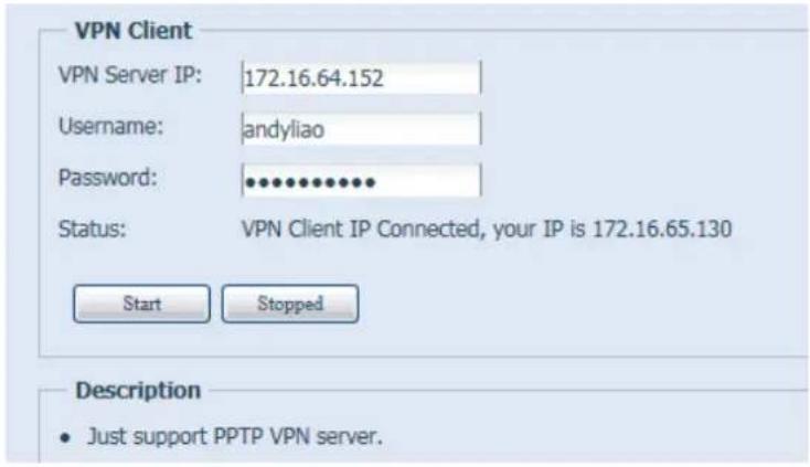
text_image
VPN Client VPN Server IP: 172.16.64.152 Username: andyliao Password: ••••••••••• Status: VPN Client IP Connected, your IP is 172.16.65.130 Start Stopped Description • Just support PPTP VPN server.NOTE
- Please notice that the connection to the VPN server only supports PPTP.
VPN Server
This storage device provides VPN server service and this allows remote access to this device via a secure connection. Settings can be found in the "Application Server" tab as seen below
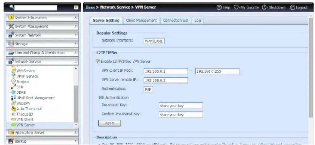
text_image
Home > Network Service > VPN Server Server Setting Client Management Connection List Log Regular Settings Network Interface: WAN/LW1 L2TP/IPSec Enable L2TP/IPSec VPN Server VPN Client IP Pool: 192.168.0.1 192.168.0.255 VPN Server remote IP: 192.168.0.2 Authentication: PAP IKE Authentication Pre-shared Key: share-your-key Confirm Pre-shared Key: share-your-key Apps Description - Post 50: 500, 1701, 4503 on VPN outlet. Please open here on the subchannel or if you use a direct internet connectionTo setup your VPN server you must first choose the NIC interface from the drop down menu and complete the rest of the necessary information.
Below is a description of each item:
| VPN Server | |
| Item | Description |
| Network Interface | Select the NIC interface to use for VPN server |
| Enable L2TP/IPSec VPN Server | Check to enable L2TP/IPSec VPN server service |
| VPN Client IP Pool | Input the IP range for client IP. |
| VPN Server remote IP | Input the IP for the VPN server for VPN client connection |
| Authentication | Input domain name with DDNS registry. |
| IKE Authentication | Internet Key Exchange for authentication while connection is made. |
| Pre-shared key | Input the key for connection authentication in between VPN client and server. |
| Confirm Pre-shared Key | Confirm the key |
| Apply | Click "Apply" to confirm the changes. |
For the VPN client access control, simply click on "Client Management" tab. It will list all the users on this system and default "Allowed" for VPN connection. Un-tick the check box and confirm with the "Apply" button if users are prohibited from connecting with this VPN server.
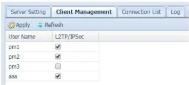
text_image
Server Setting Client Management Connection List Log Apply Refresh User Name L2TP/IPSec pm1 ✓ pm2 ✓ pm3 □ aaa ✓To get the on-line connection list, click on the "Connection List" tab. It will display connected users with associated connection information.
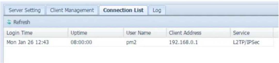
text_image
Server Setting Client Management Connection List Log Refresh Login Time Uptime User Name Client Address Service Mon Jan 26 12:43 08:00:00 pm2 192.168.0.1 L2TP/IPSecTo retrieve the VPN service connection history information, click on "Log" tab. It will display the complete access log of the VPN service.
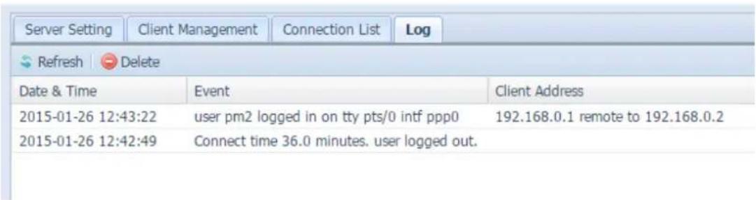
text_image
Server Setting Client Management Connection List Log Refresh Delete Date & Time Event Client Address 2015-01-26 12:43:22 user pm2 logged in on tty pts/0 intf ppp0 192.168.0.1 remote to 192.168.0.2 2015-01-26 12:42:49 Connect time 36.0 minutes. user logged out.
text_image
NOTE The VPN server only supports L2TP/IPSec connection.Application Server
The Thecus IP storage supports build-in application such as iTunes server. The Thecus IP storage provides activation of the iTunes Server on the device. You will be able to play music files on this device with your iTunes client software directly. The following section shows you how.
iTunes® Server
With the built-in iTunes server capability, Thecus IP storage enables digital music to be shared and played anywhere on the network!
From the Network Service menu, choose the iTunes Server item, and the iTunes Configuration screen appears. You may enable or disable the iTunes Service from here. Once enabled, enter the proper information for each field and press Apply to save your changes.
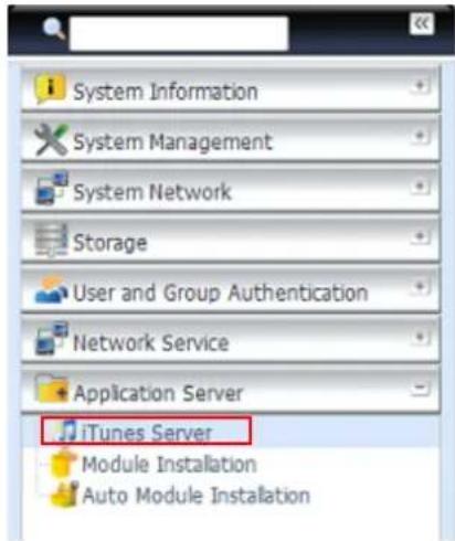
text_image
System Information System Management System Network Storage User and Group Authentication Network Service Application Server iTunes Server Module Installation Auto Module Installation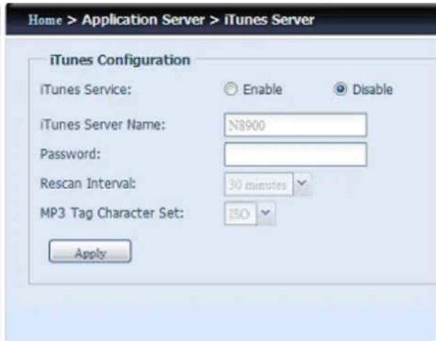
text_image
Home > Application Server > iTunes Server iTunes Configuration iTunes Service: Enable Disable iTunes Server Name: N8900 Password: Rescan Interval: 30 minutes MP3 Tag Character Set: ISO ApplySee the following table for a detailed description of each field:
| iTunes Server Configuration | |
| Item | Description |
| iTunes Service | Enable or disable the iTunes Service. |
| iTunes Server Name | Name used to identify Thecus IP storage to iTunes clients. |
| Password | Enter a password to control access to your iTunes music. |
| Rescan Interval | Rescan interval in seconds. |
| MP3 Tag Encode | Specify tag encoding for MP3 files stored in Thecus IP storage. All ID3 tags will be sent out in UTF-8 format. |
Once the iTunes service is enabled, Thecus IP storage will make all music located in the Music folder available for iTunes-equipped computers on the network.
App Installation
From the login page, other than admin, web disk and Piczza (Photo server) the app icon is a newly added feature for this FW release. After an app has been installed, a new option will be available to "Show in Login".

text_image
App Management Ena... Type Name Version Description Last Status Action Show in Lo... Yes System Usb/eSATA Schedule Bac 1.00.03 USB/eSATA S... i x ✓If this option is enabled then, when login to the system, the module icon will be available for all valid users to login through.
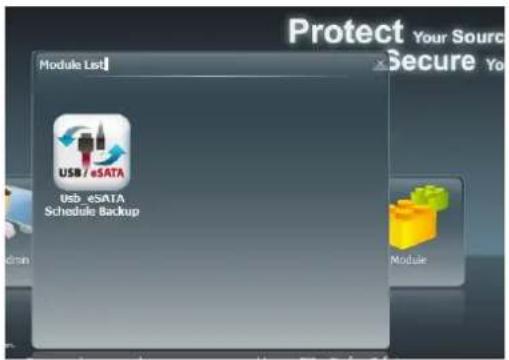
text_image
Protect Your Source Secure Your Module List USB / eSATA USB eSATA Schedule Backup ModuleAuto App Installation
Choose the Auto App Installation item and the Auto App Installation screen appears. The default for this apps list is located online. So if the Thecus IP storage is capable to connect to Internet, then it will automatically link to the Thecus official website and list the available apps. Please refer the screen shot below.
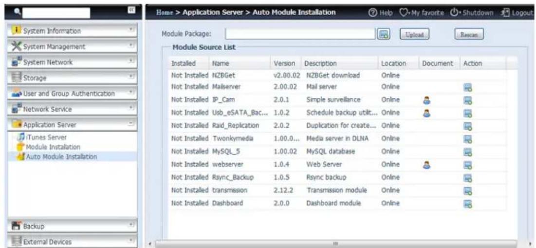
text_image
Home > Application Server > Auto Module Installation Help My favorite Shutdown Logout Module Package: Upload Rescan Module Source List Installed Name Version Description Location Document Action Not Installed NZBGet v2.00.02 NZBGet download Online Not Installed Mailserver 2.00.02 Mail server Online Not Installed IP_Cam 2.0.1 Simple surveillance Online Not Installed Usb_eSATA_Bac... 1.0.2 Schedule backup utilt... Online Not Installed Raid_Replication 2.0.2 Duplication for create... Online Not Installed Twonkymedia 1.00.0... Media server in DLNA Online Not Installed MySQL_5 1.00.02 MySQL database Online Not Installed webserver 1.0.4 Web Server Online Not Installed Rsync_Backup 1.0.5 Rsync backup Online Not Installed transmission 2.12.2 Transmission module Online Not Installed Dashboard 2.0.0 Dashboard module Online| Auto Module Source List | |
| Item | Description |
| Installed | Status of module |
| Name | Module name |
| Version | The version of the released module |
| Description | The description of the module |
| Location | The module is either located on-line or disk |
| Document | The available documentation of the module |
| Action | To install or delete module.p.s. If the module list from on-line, then no delete option will be available |
| Rescan | Click to rescan from both on-line and disk |
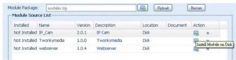
text_image
Module Package: modules.zip Module Source List Installed Name Version Description Location Document Action Not Installed IP_Cam 2.0.1 IP Cam Disk Not Installed Twonkymedia 1.0.0 Twonkymedia Disk Not Installed webserver 1.0.4 Webserver Disk Install Module on DiskAfter clicking on "Action" to install a module, the module will become available under the list of Module Installation. Please go to Module installation and click "Enable" to activate the module.
Backup
There are a number of ways to back up data with the Thecus IP storage.
Dual DOM (N12000 series/N16000 series/N8900 series only)
The unique Dual DOM feature can now perform "Auto Repair". The Thecus NAS will backup up to five versions of the system configuration either by the default timing of 1:00am every day automatically or as scheduled by the user.
This unique "Auto Repair" will be triggered if the primary DOM has a booting issue. In this instance, the 2^nd DOM will take over the boot function. Then, the system will automatically load the most recent system configuration backup image to repair the primary DOM.
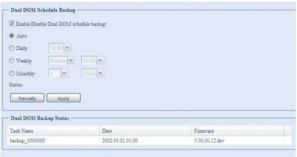
text_image
Dual DOM Schedule Backup ✓ Enable/Disable Dual DOM schedule backup ● Auto ○ Daily 00:00 ○ Weekly Sunday 00:00 ○ Monthly 1 00:00 Status: Manually Apply Dual DOM Backup Status Task Name Date Firmware backup_0000000 2002/01/01 01:00 5.00.00.12.devRsync Target Server
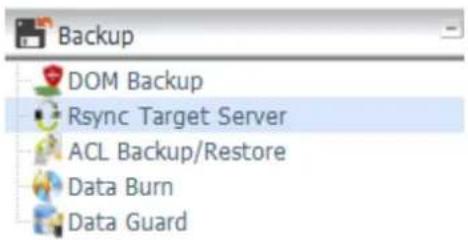
text_image
Backup DOM Backup Rsync Target Server ACL Backup/Restore Data Burn Data GuardWhen it comes to backing up your data, it's very important to have flexibility. Data guard provides you with many options, including full backup for all shares, custom backup for selected shares and iSCSI volume backup. Being based on the Linux operating system, it is also much more stable and experiences much less frequent data loss during transfer than other remote backup systems.
-For this tutorial you will need to use Rsync Target Server (Step 1) and Data Guard (Step 2+3) under Backup for this client/server backup feature. It also can be named for function "Remote Replication".
Step 1 - Enabling Rsync on your target (backup) NAS
-Log in to your target (backup) NAS through the UI in your web browser
-Go to Rsync Target Server under Backup in the menu of the UI
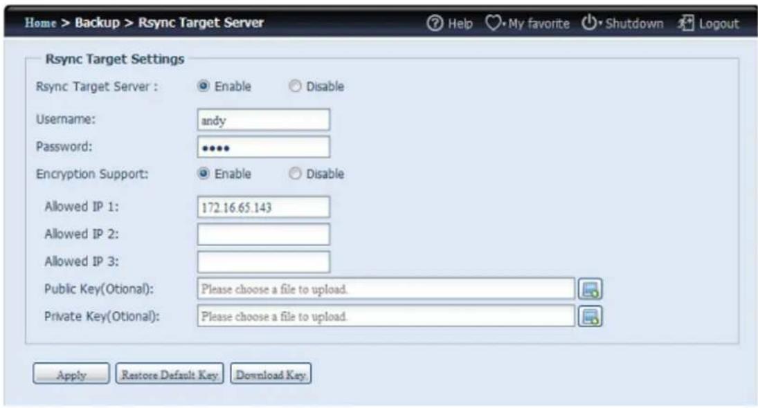
text_image
Home > Backup > Rsync Target Server Help My favorite Shutdown Logout Rsync Target Settings Rsync Target Server : Enable Disable Username: andy Password: ••••• Encryption Support: Enable Disable Allowed IP 1: 172.16.65.143 Allowed IP 2: Allowed IP 3: Public Key(Otional): Please choose a file to upload. Private Key(Otional): Please choose a file to upload. Apply Restore Default Key Download Key- Enable Rsync Target Server
- Add a username and password (they can be different than your NAS's username and password)
- Select Apply
NOTE
- You will need this user name and password while the data is going to remotely backup to this Rsync target server.
Now Rsync is turned on your NAS, which means it can be used as a target for Rsync backup, in other words, only the backup NAS needs to be activated in this way.
ACL Backup and Restore
The ACL backup and restore feature enables the system ACL (Access Control List) to be backed up on the RAID volume based to other location and restored if needed.
Let's look at the example bellow to see how it works.
We have one system with a RAID volume "RAID", select "Backup" to backup this RAID volume's ACL to other location. The current RAID volume "RAID" has share folder as listed on right hand screen shot.
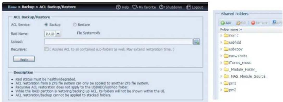
text_image
Home > Backup > ACL Backup/Restore Help My favorite Shutdown Logout ACL Backup/Restore ACL Service: Backup Restore Raid Name: RAID File Systemxfs Upload: Recursive: ( Apples ACL to all contained sub-folders as well. May extend restoration time. ) Apply Description • Raid status must be healthy/degraded. • ACL restoration from a ZFS file system can only be applied to another ZFS file system. • Recursive ACL restoration does not apply to the USBHDD/usbhdd folder. • While the RAID partition is restoring/backing up ACL, its folders will not be shown within the UL. • ACL restoration/backup cannot be applied to stacked folders. Shared Folders Add Edit Remove NT Folder name >> nsync usbhdd usbcopy naswebsite iTunes_music Module_Folder_ NAS_Module_Source_ pm1 pm2For the ACL restore, it can be restored in the same system or used in another unit. For example, let's restore the ACL backup file to another unit. This unit has a RAID volume "RAIDpm" with share folders as listed on right hand screen shot.
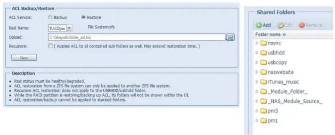
text_image
ACL Backup/Restore ACL Service: Backup Restore Raid Name: RAIDpm File Systemcfs Upload: C:\fakepath\folder_acl.bin Recursive: ( Apples ACL to all contained sub-folders as well. May extend restoration time. ) Next Description • Raid status must be healthy/degraded. • ACL restoration from a ZFS file system can only be applied to another ZFS file system. • Recursive ACL restoration does not apply to the USBHDD/usbhdd folder. • While the RAID partition is restoring/backing up ACL, its folders will not be shown within the UI. • ACL restoration/backup cannot be applied to stacked folders. Shared Folders Add Edit Remove Folder name >> nsync usbhdd usbcopy naswebsite iTunes_music _Module_Folder_ _NAS_Module_Source_ pm3 pm1After inputting the ACL backup file and clicking the "Next" button, the system will show another screen to list the matched folders in between the backup file and this RAID volume. Just select the desired folders for the ACL restore.
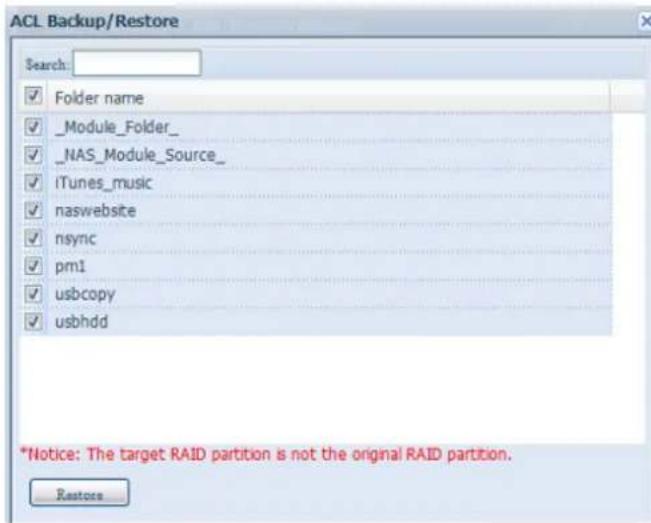
text_image
ACL Backup/Restore Search: ✓ Folder name ✓ _Module_Folder_ ✓ _NAS_Module_Source_ ✓ iTunes_music ✓ naswebsite ✓ nsync ✓ pm1 ✓ usbcopy ✓ usbhdd *Notice: The target RAID partition is not the original RAID partition. RestoreNOTE
- The ACL backup will only back to share folder level; it does not apply to its sub-layer.
- The ACL backup/restore can be used among ext3/ext4/XFS file system. ZFS can only be used with other RAID volume with ZFS file system created.
- If recursive has been checked during the ACL restoration, it will apply to all of its sub-folders with the same permission.
Data Burn
The data burn is featured to support 3 different modes of data burning for files/folders to and from image file and physical optical disk.
The 3 different modes are "Write Files/folders to disc", "Write image to disk" and "Write files/folders to image".
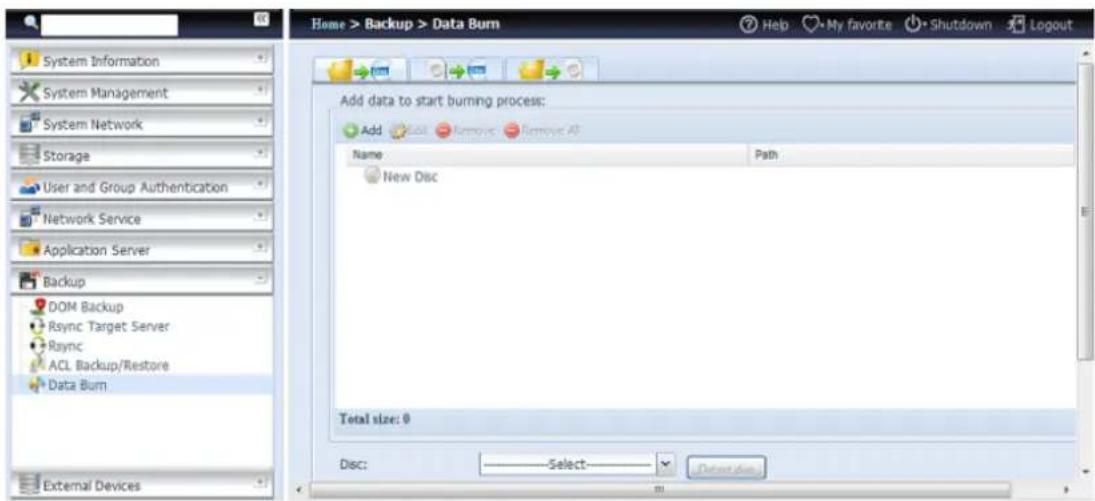
text_image
Home > Backup > Data Burn System Information System Management System Network Storage User and Group Authentication Network Service Application Server Backup DOM Backup Rsync Target Server Rsync ACL Backup/Restore Data Burn External Devices Add data to start burning process: Add Edit Remove Remove All Name Path New Disc Total size: 0 Disc: Select... Display Back1. Write Files/folders to disc

text_image
Home > Backup > Data Burn Add Write file/folders to disc process: Add Edit Remove Remove All Name New Disc Add data to start burning process View Search NAS_Public USBCopy USBHDD _Module_Folder_ _NAS_Module_Source_ _NAS_Picture_ eSATAHDD iSCSI_pm1 iSCSI_pm2 iTunes_music ap2 laptest snapshot test name NAS_Public USBCopy USBHDD _Module_Folder_ _NAS_Module_Source_ _NAS_Picture_ eSATAHDD iSCSI_pm1 iSCSI_pm2 iTunes_music ap2 laptest snapshot test Select Cancela. Click the Add button and the NAS share list appears.
b. Select files/folders which you would like to burn. All of the selected folders/files will be seen under the disc label name "New Disc". The disc label name can be changed by clicking on
it and press "Edit" from menu bar. The selected folders/files also can be removed by clicking on them and then pressing "remove" or "remove all" for all selected items.
c. Select from the installed USB or SATA(for N6850/N8850/N10850) burning devices. Please click the "detect disc" button to check the status once the disc is inserted.
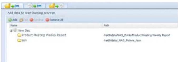
text_image
Add data to start burning process: Add Remove All Name Path New Disc Product Meeting Weekly Report IranSDataNAS_PublicProduct Meeting Weekly Report son IranSDataNAS_Picture_isond. Select the burning speed from the drop down list.
e. Select whether disc data verification is required or not.
f. Click "Burn" to start disc burning.
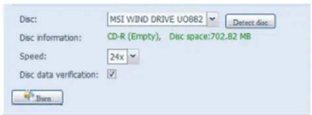
text_image
Disc: MSI WIND DRIVE UO882 Detect disc Disc information: CD-R (Empty), Disc space:702.82 MB Speed: 24x Disc data verification: ✓ Burn2. Write image file to disc
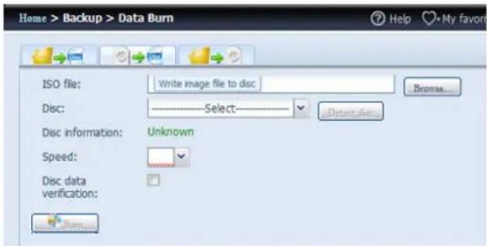
text_image
Home > Backup > Data Burn ISO file: Write image file to disc Disc: Select Disc information: Unknown Speed: Disc data verification:a. Click "Browser" and the NAS share list will appear to locate the desired image file burn.
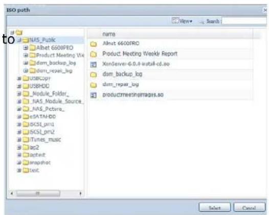
text_image
ISO path View+ Search NAS_Pulk Alnet 6600FRO Product Meeting View dam_backup_log dam_repair_log USBcopy USBHD0 _Module_Folder_ NAS_Module_Source_ NAS_Pictora_ eSATAHDD SCSL_prn1 SCSL_prn2 iTunes_music lap2 actest snapshot test name Alnet 6600FRO Product Meeting Weekly Report XinServer-6.0.4-install-cd.so dam_backup_log dam_repair_log productmeetingsages.so Select Cancelb. Select the ISO file.

text_image
ISO file: id0/data/NAS_Public/XenServer-6.0.0-install-cd.iso Browse...c. Select from the installed USB or SATA(for N6850/N8850/N10850) burning devices. Please click the "detect disc" button to check the status once the disc is inserted.
d. Select the burning speed from the drop down list.
e. Select whether disc data verification is required or not.
f. Click "Burn" to start disc burning.
3. Create image file from files/folders
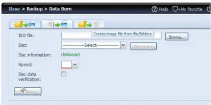
text_image
Home > Backup > Data Burn ISO file: Create image file from file/folders Disc: Select Disc information: Unknown Speed: Disc data verification:a. Click the Add button and the NAS share list will appear.
b. Select the files/folders which you would like to burn. All of the selected folders/files will appear under the disc label name "New Disc". The disc label name can be changed by clicking on it
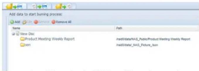
text_image
Add data to start burning process: Add Edit Remove Remove All Name Path New Disc Product Meeting Weekly Report Iran0Data/NAS_PublicProduct Meeting Weekly Report son Iran0Data/NAS_Picture_Nonand pressing "Edit" from the menu bar. The selected folders/files also can be removed by clicking on them and pressing "remove" or "remove all" for all the selected items.
c. Input the path where the ISO file is going to be stored, you can press the "Browse" button to have the share list appear.
d. Input the ISO file name for burned image file.
e. Click "Burn" to start the ISO file burning.
NOTE
- The data burn does not support rewriteable media if it has been burned with left space. On the other hand, the used rewriteable media will be erased first then carry on with burning.
Data Guard (Remote Backup)
Setting up your backup task and schedule on your source NAS
-Log in to your other NAS (your source NAS) through the UI in your web browser
-Go to Data Guard under Backup in the menu of the UI
-From the Data Guard function list, choose Add

text_image
Add Edit Remove Start Stop Restore Log Restore NAS Configuration Task Name Source Path Source Folder Target Path Last Run Time Backup Type Status Category: remote (3)| Remote Data backup | |
| Item | Description |
| Add | Add new task. |
| Edit | Edit select task. |
| Remove | Remove select task |
| Start | If associated task has been setup in schedule and like to start at once, click on to start task right away. |
| Stop | Stop the associated running task. The other scenario is if a task has been setup in real-time then clicking “Stop” can terminate the running process. Simple click ‘Start’ to re-start the real-time operation. |
| Restore | Restore the associated task |
| Log | Click to view the associated task in process details. |
| Restore NAS Configuration | Click to restore system configuration from selected destination to source unit. More details will describe in sections. |
The data backup setup wizard appears as below, click on 'Remote Backup':
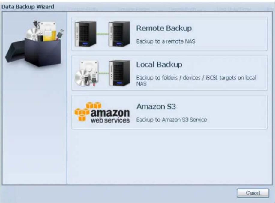
text_image
Data Backup Wizard Remote Backup Backup to a remote NAS Local Backup Backup to folders / devices / iCSI targets on local NAS amazon S3 web services Backup to Amazon S3 Service CancelThen 3 different selections appear and can be chosen from:
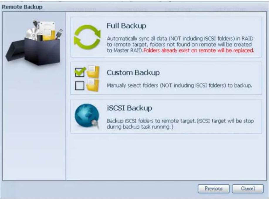
text_image
Remote Backup Full Backup Automatically sync all data (NOT including iSCSI folders) in RAID to remote target, folders not found on remote will be created to Master RAID.Folders already exist on remote will be replaced. Custom Backup Manually select folders (NOT including iSCSI folders) to backup. iSCSI Backup Backup iSCSI folders to remote target.(iSCI target will be stop during backup task running.) Previous Cancel| Remote Data backup | |
| Item | Description |
| Full Backup | The “Full backup” will have all shares from source backup to destination. It could also create shares automatically from destination if it is not existent. This only applies if the target server is the same model as the source. |
| Custom Backup | The “Custom backup” allows user to choose desired shares backup to destination. |
| iSCSI Backup | The “iSCSI backup” can backup iSCSI volume as single file to destination. |
Full Backup
Click on full backup and the setup screen appear as below. Fill in the remote target IP (Destination) and port (need to be changed only if this port is already in use). If encryption is required then enable it. Please make sure the associated target server also has encryption enabled.
Carry on with inputting valid remote target server account name and password.
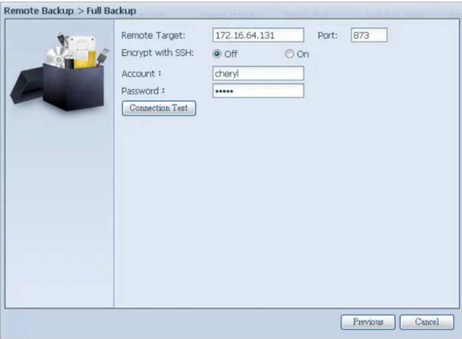
text_image
Remote Backup > Full Backup Remote Target: 172.16.64.131 Port: 873 Encrypt with SSH: Off On Account : cheryl Password : ***** Connection Test Previous CancelAfter the settings are complete, please click on "Connection Test". The source unit will try to connect with the associated target system. If a connection can be built up successfully then "Connection passed" will be prompted, otherwise "Failed" will appear.
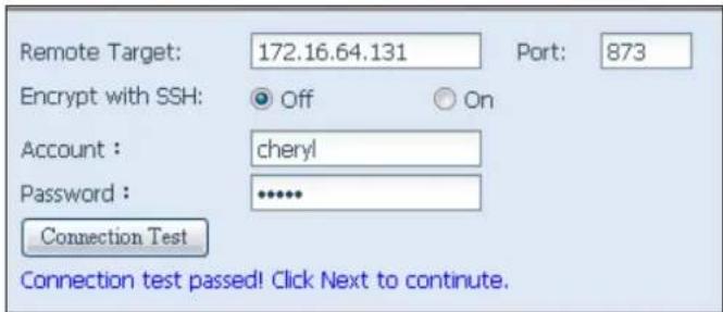
text_image
Remote Target: 172.16.64.131 Port: 873 Encrypt with SSH: Off On Account : cheryl Password : ****** Connection Test Connection test passed! Click Next to continue.Click "Next" and more setting will appear.
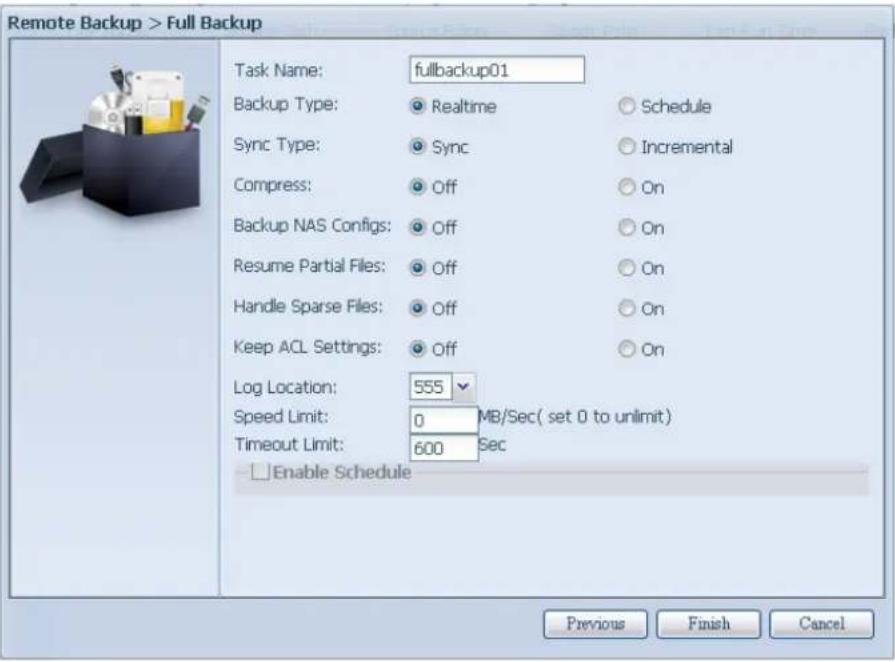
text_image
Remote Backup > Full Backup Task Name: fullbackup01 Backup Type: Realtime Schedule Sync Type: Sync Incremental Compress: Off On Backup NAS Configs: Off On Resume Partial Files: Off On Handle Sparse Files: Off On Keep ACL Settings: Off On Log Location: 555 Speed Limit: 0 MB/Sec( set 0 to unlimit) Timeout Limit: 600 Sec Enable Schedule Previous Finish Cancel-Fill out all the necessary details and choose your parameters
| Add Rsync Backup Task | |
| Item | Description |
| Task Name | This is how this task will appear in the task list. |
| Backup Type | Real time:It will backup folders/files from source to target on the fly. On the other hand, any changes from the source will back up to the target right away.Schedule:The task will start only according to the schedule. |
| Sync Type | Sync mode:Makes your source match your target completely; deleting and adding files on your target as they are deleted and added on your source.Incremental Mode :Makes your source match your target and keep all old files; adding files on your target as they are added on your source, but NOT deleting files on your target as they are deleted on your source. |
| Compress | With this option, compress the file data as it is sent to the destination machine, which reduces the amount of data being transmitted – something that is useful over a slow connection. |
| Backup NAS Config | Enabling this will back up the source unit system configurations to the designed path on the target system. |
| Handle Sparse File | Try to handle sparse file efficiently so they take up less space on the destination. |
| Keep ACL Setting | It will backup not just data itself but also ACL configuration with associated folders/files. |
| Log Location | Choose the folder to save the log details while the task is executed. |
| Speed Limit | Input the bandwidth control for data backup operation. |
| Timeout Limit | Setup the timeout when trying to build up a connection in between the source and the target system. |
| Enable Schedule | If backup is set as "Schedule", please input the related period and time. |
After the required fields are filled and the parameters are setup, click 'Finish' to complete. The data guard task will appear in the list as shown below.

text_image
Home > Backup > Data Guard Add Edit Remove Start Stop Restore Log Task Name Source Path Source Folder Target Path Last Run Time Backup Type Status Category: remote (I) fulbackup01 * 172.16.64.131:/ Realtime ProcessingFrom the task list, you can now see the newly added task "fullback01". The backup is setup as "real time". From the status field, "Processing" can be read as the back-up is performed on the fly.
Custom Backup
The custom backup setting is similar to the full backup. The only differences are explained below:
- Inputs the share folder name of target sever where the source is going to backup. The sub-folder can be left as blank.

text_image
Remote Backup > Custom Backup Remote Target: 172.16.64.131 Port: 873 Encrypt with SSH: Off On Account : cheryl Password : ***** Target Folder : Backup / Connection Test Connection test passed! Click Next to continue. Next Cancel- Select the source share folder(s) which are desired to be backed up to the target server. You can also click on "Select All" from top right corner check box.
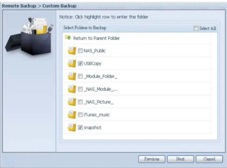
text_image
Remote Backup > Custom Backup Notice: Click highlight row to enter the folder Select Folders to Backup Return to Parent Folder NAS_Public USBCopy _Module_Folder_ NAS_Module_... NAS_Picture_ iTunes_music snapshot Previous Next Cancel- Click "Next" and more setting appears. These are the as the settings for "Full backup"
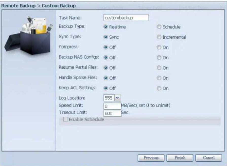
text_image
Remote Backup > Custom Backup Task Name: custombackup Backup Type: Realtime Schedule Sync Type: Sync Incremental Compress: Off On Backup NAS Configs: Off On Resume Partial Files: Off On Handle Sparse Files: Off On Keep ACL Settings: Off On Log Location: 555 Speed Limit: 0 MB/Sec( set 0 to unlimit) Timeout Limit: 600 Sec Enable Schedule Previous Finish Cancel- Click "Finish" and the data guard task will appear in the list as shown below.
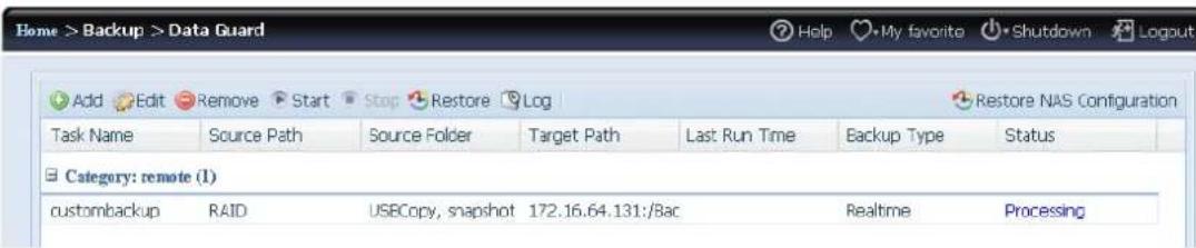
text_image
Home > Backup > Data Guard Add Edit Remove Start Stop Restore Log Task Name Source Path Source Folder Target Path Last Run Time Backup Type Status Category: remote (1) custombackup RAID USBCopy, snapshot 172.16.64.131:/8ac Realtime ProcessingFrom the task list, you can now see the newly added "customback01". This backup is setup as "schedule".
iSCSI Backup
If the source unit contains iSCSI volume, it can be backed up to the target unit as a single file. The procedure is the same as for the previous "Full backup" and "Custom backup", select "iSCSI backup" from data guard wizard.
- Inputs the share folder name of the target sever where the source is going to backup. The sub-folder can be left as blank.
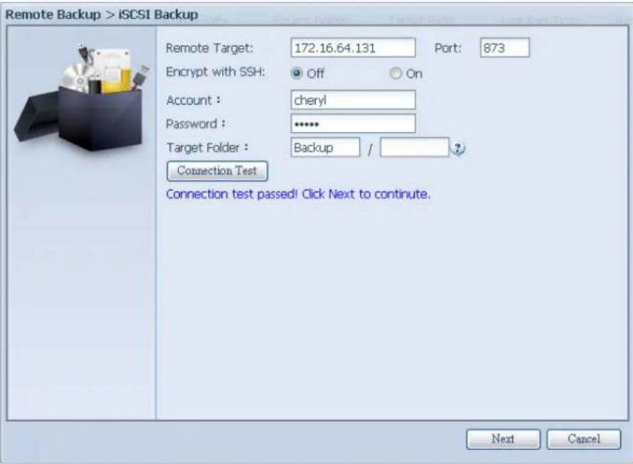
text_image
Remote Backup > iSCSI Backup Remote Target: 172.16.64.131 Port: 873 Encrypt with SSH: Off On Account : cheryl Password : ****** Target Folder : Backup / Connection Test Connection test passed! Click Next to continue. Next Cancel- Select the iSCSI target volume which you wish to back up to the target server.
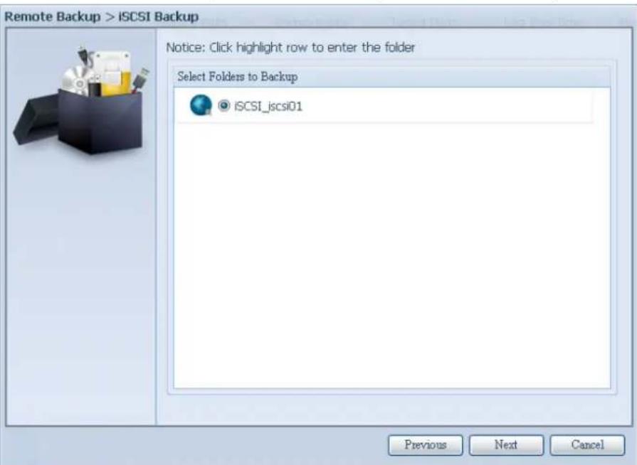
text_image
Remote Backup > iSCSI Backup Notice: Click highlight row to enter the folder Select Folders to Backup iSCSI_icsi01 Previous Next Cancel- Click "Next" and more settings will appear. It is slightly differing from "Full backup" and "Custom backup". Only "Schedule" backup is supported with less options.
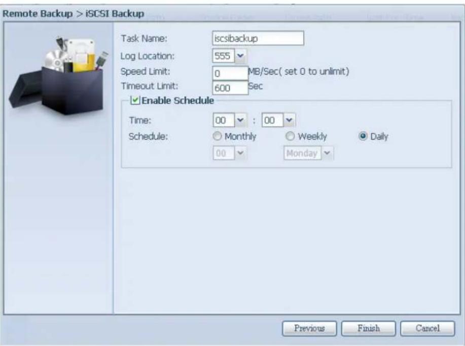
text_image
Remote Backup > iSCSI Backup Task Name: iscsibackup Log Location: 555 Speed Limit: 0 MB/Sec( set 0 to unlimit) Timeout Limit: 600 Sec Enable Schedule Time: 00 : 00 Schedule: Monthly Weekly Daily 00 Monday Previous Finish Cancel- Click "Finish" and the data guard task will appear in the list as shown below.

text_image
Home > Backup > Data Guard Add Edit Remove Start Stop Restore Log Restore NAS Configuration Task Name Source Path Source Folder Target Path Last Run Time Backup Type Status Category: remote (1) scsbackup ISC5I_scsi01 172.16.64.131:/Bac Schedule(Daily)From the task list, you can now see the newly added "iscsiback". This backup is setup as "schedule".
NOTE
- The source folder name will use iSCSI_+target volume name. So here it is displayed as "iSCSI_pmtest". pmtest is the iSCSI target name when the iSCSI target was created.
The iSCSI backup can see the result as below. The task "iSCSI_pmtest" has backup to target 172.16.66.131 and share folder NAS_Public with file "iSCSI_pmtest".
To restore a backup from the backup task, simply select a task from the task list then click "Restore" from the function bar. The restore task will start to have the associated files/folders from the target server restored to the source.
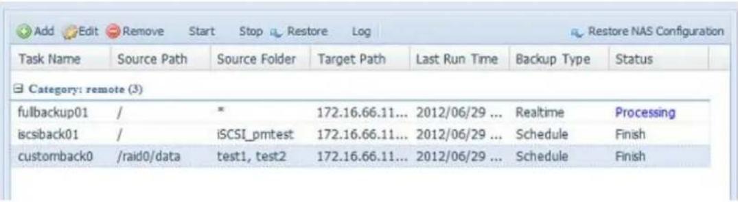
text_image
Add Edit Remove Start Stop Restore Log Restore NAS Configuration Task Name Source Path Source Folder Target Path Last Run Time Backup Type Status Category: remote (3) fullbackup01 / * 172.16.66.11... 2012/06/29 ... Realtime Processing iscsback01 / iSCSI_pmtest 172.16.66.11... 2012/06/29 ... Schedule Finish customback0 /raid0/data test1, test2 172.16.66.11... 2012/06/29 ... Schedule FinishNOTE
- To restore task with backup type set as "Real time", first you need to stop the task then you can proceed with the restore operation.
Restore NAS Configuration
This is a useful feature if the system configuration needs to be restored to a brand new unit. Let's go thru the following example to see how it works.
The original source system has 3 RAID volume, "RAID", "RAID10" and "RAID20", and has backed up the system configurations to the target server.
| RAID Management | ||||||||
| Create Edit Global Hot Spare | ||||||||
| Mas... RAID | ID | RAID Level | Status | Disks Used | Total Capacity | Data Capacity | ||
| * | RAID J | Healthy | 10 | 929 GB | 11.4 GB / 928.7 GB | |||
| RAID01 J | Healthy | 9 | 929 GB | 928.5 GB | ||||
| RAID20 J | Healthy | 8 | 929 GB | 928.5 G8 | ||||
The brand new source unit only has a 1 RAID volume 'RAID".
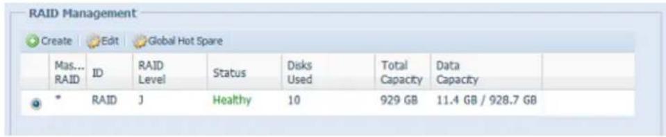
text_image
RAID Management Create Edit Global Hot Spare Mas... RAID ID RAID Level Status Disks Used Total Data Capacity Capacity * RAID J Healthy 10 929 GB 11.4 GB / 928.7 GB- When adding a new backup task with "Full backup" or "Custom backup" and enabling the option "Backup NAS Config" as shows below, the source unit system configurations are then backed up to the designed path on the target system every time the task is executed.

text_image
Remote Backup > Full Backup Task Name: FullBackup Backup Type: Realtime Schedule Sync Type: Sync Incremental Compress: Off On Backup NAS Configs: Off On Resume Partial Files: Off On Handle Sparse Files: Off On Keep ACL Settings: Off On Log Location: 555 Speed Limit: 0 MB/Sec( set 0 to unlimit ) Timeout Limit: 600 Sec Enable Schedule Previous Finish Cancel- Click on "Restore NAS Configuration" and the screen shown below will appear. Input the target server's IP address where the system configuration has been backed up, and necessary authentication info. Confirm by doing a "Connection Test" to make sure the communication between the source and the target server works.
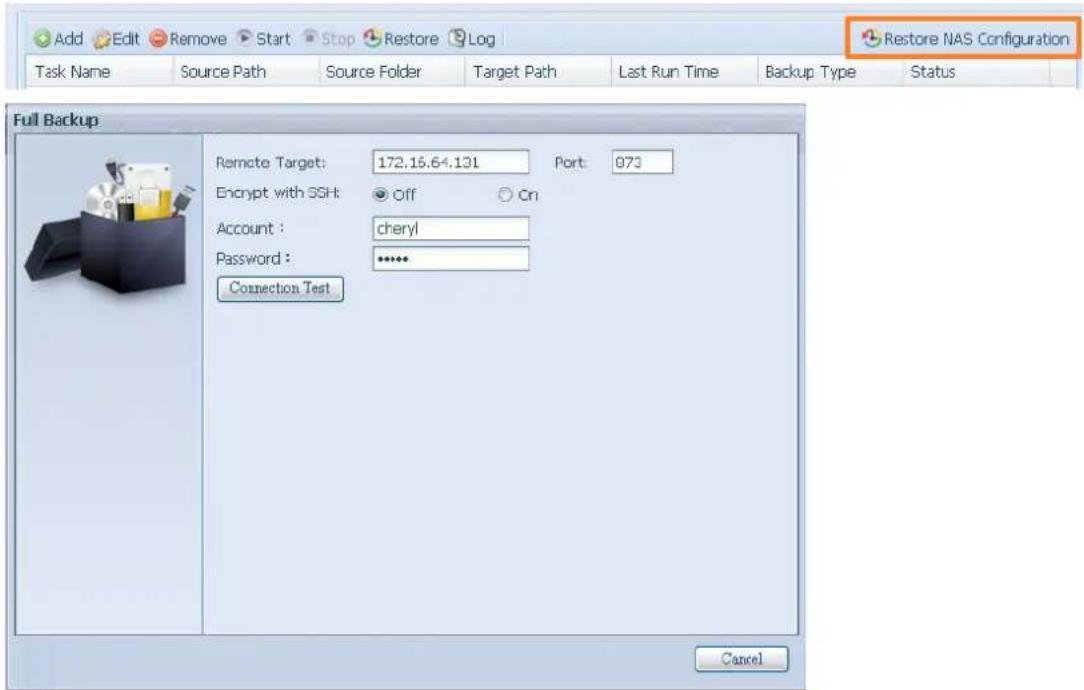
text_image
Add Edit Remove Start Stop Restore Log Task Name Source Path Source Folder Target Path Last Run Time Backup Type Status Full Backup Remote Target: 172.15.64.131 Port: 973 Encrypt with SSH: Off Cn Account : cheryl Password : ***** Connection Test Cancel- Click "Next" and a screen will appear as shown below. It has the listed available system configuration backup files. Select the one you want and click next. You also have the option to download the current system configuration before restoring from the backup file.
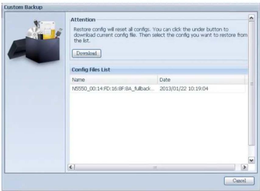
text_image
Custom Backup Attention Restore config will reset all configs. You can click the under button to download current config file. Then select the config you want to restore from the list. Download Config Files List Name Date N5550_00:14:FD:16:8F:8A_fullback... 2013/01/22 10:19:04 Cancel- After clicking "Next", a screen will appear as shown below. Listed on the left hand side, you will see the configuration backup details which contain the 3 RAID volumes. On the right hand side, you will see a list of single "RAID" volume. You may roll back to previous page to recall the example we have taken.
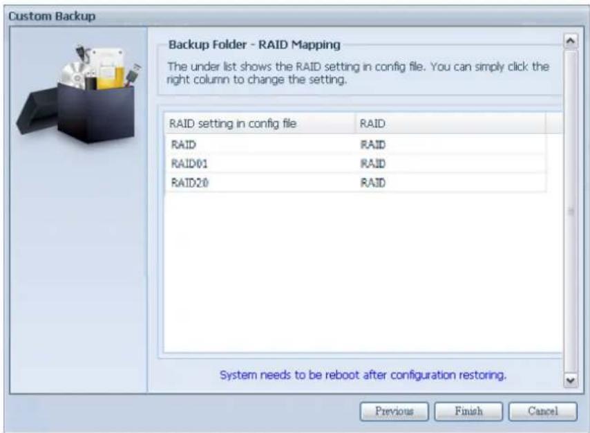
text_image
Custom Backup Backup Folder - RAID Mapping The under list shows the RAID setting in config file. You can simply click the right column to change the setting. RAID setting in config file RAID RAID RAID RAID01 RAID RAID20 RAID System needs to be reboot after configuration restoring. Previous Finish Cancel- The backup configuration has different numbers of RAID volume than the current system (3 vs 1). It can be kept as the RAID volume mapping arranged by the system, then carry on to click "Finish". This means that all 3 RAID volumes configuration such as share folder etc. will all restore to the current unit in the RAID volume "RAID".
- In other circumstances, if the current unit contains 2 RAID volumes, then it can be chosen from the left hand side of system backup configuration RAID volume list which RAID volume to map to the current system.
Let's see the following screen to make it clearer.
The current system has 2 RAID volumes, "RAID" and "RAIDa". Select the RAID volume from the backup configuration volume list which is going to be mapped to the RAID volume of the current system. Simply click on the right hand side of "RAIDa" and a drop down list will appear. Now you can choose which volume to map with. In this case the "RAID01" volume from the system backup configuration will be mapped to the volume "RAIDa" of the current unit. Once again, it means all the shares that were created in the volume "RAID01" will be restored to volume "RAIDa" of the current system.
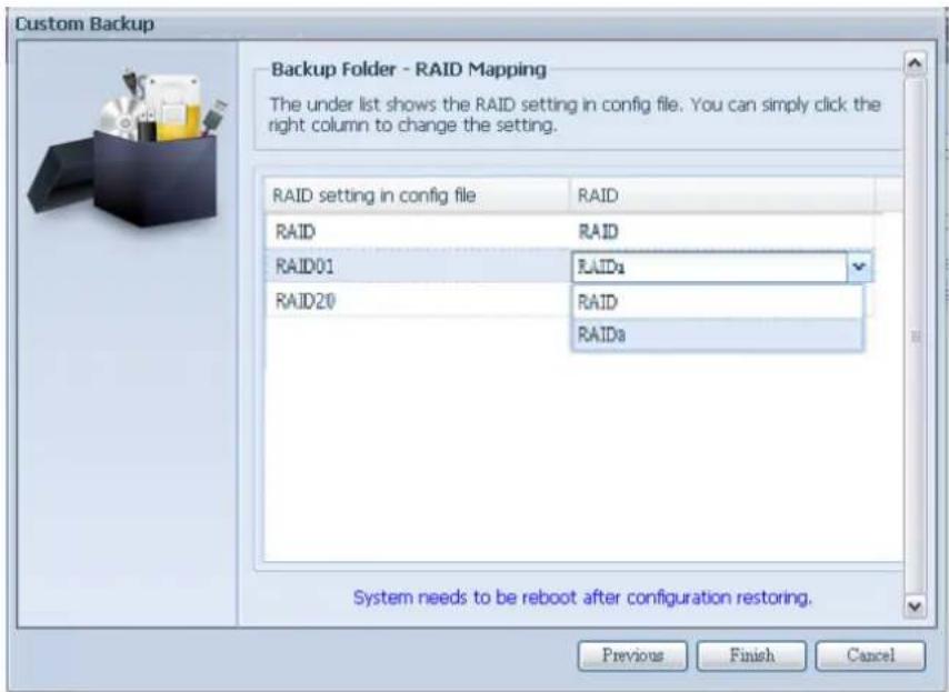
text_image
Custom Backup Backup Folder - RAID Mapping The under list shows the RAID setting in config file. You can simply click the right column to change the setting. RAID setting in config file RAID RAID RAID RAID01 RAIDs RAID20 RAID RAIDs System needs to be reboot after configuration restoring. Previous Finish CancelData Guard (Local Backup)
The Thecus product provides complete backup solution between Thecus NAS systems as well as between folders of local systems. For remote data guard backup, please refer to Data Guard (Remote backup).

text_image
Add Edit Remove Start Stop Restore Log Restore NAS Configuration Task Name Source Path Source Folder Target Path Last Run Time Backup Type Status Category: remote (3)| Local Data backup | |
| Item | Description |
| Add | Add a new task. |
| Edit | Edit selected task. |
| Remove | Remove selected task. |
| Start | Click on start to start a scheduled scan task right away. |
| Stop | Stop the associated running task. Also can be used if a task has been setup as real-time, clicking "Stop" can terminate the running process. Simply click 'Start' to re-start the real-time operation. |
| Restore | Restore the associated task. |
| Log | Click to view the associated task process details. |
| Restore NAS Configuration | Click to restore the system configurations from a selected destination to a source unit. |
-From the Data Guard function list, select Add. The data backup setup wizard appears as below, click on "Local Backup":
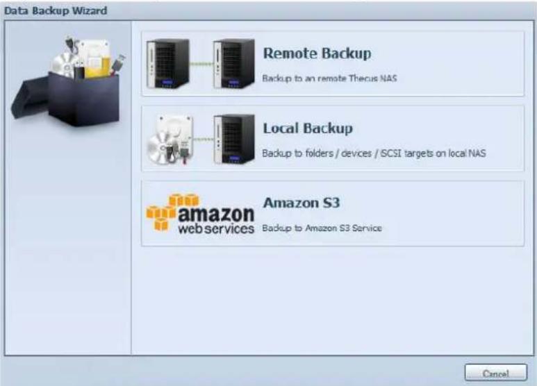
text_image
Data Backup Wizard Remote Backup Backup to an remote Thecus NAS Local Backup Backup to folders / devices / SCSI targets on local NAS amazon S3 web services Backup to Amazon S3 Service CancelThe local backup has 6 different selection you can choose from.
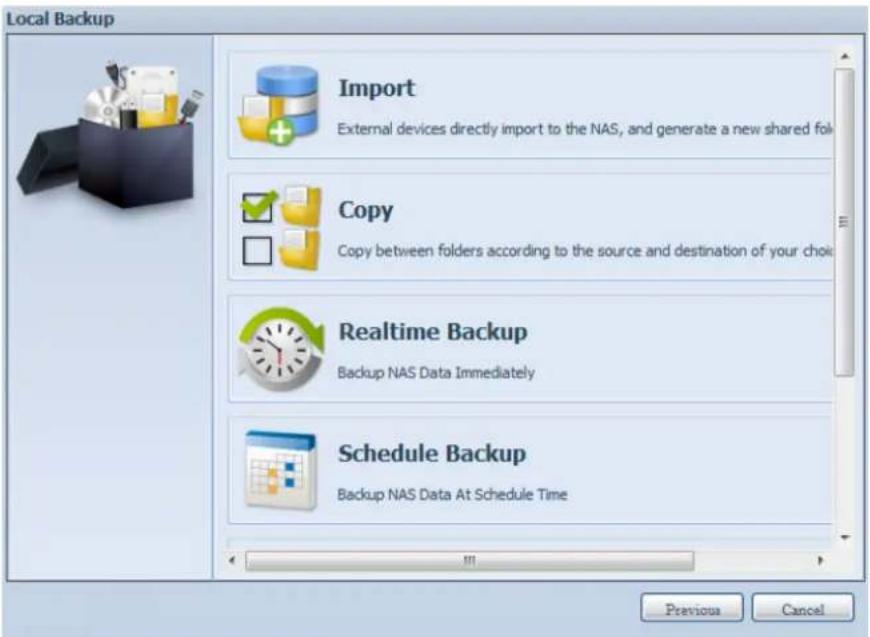
text_image
Local Backup Import External devices directly import to the NAS, and generate a new shared folk Copy Copy between folders according to the source and destination of your choice Realtime Backup Backup NAS Data Immediately Schedule Backup Backup NAS Data At Schedule Time Previous Cancel| Local Data backup | |
| Item | Description |
| Import | This is associated with external devices which are added to the system such as USB disk. You can select a folder from an external device and import it to the NAS as a share folder. |
| Copy | Copy folder to folder or NAS folder to external device or external device to NAS folder. This backup is within folder level. |
| Realtime Backup | The task will be executed on the fly between the source and the target. In other word, any changes made at the source will sync t the destination immediately. |
| Schedule Backup | The task will be executed on schedule between the source and the target. |
| iSCSI Backup | The iSCSI volume will be backup to the destination as a single file. |
| iSCSI Import | The iSCSI file can be imported from the iSCSI backup back to the destination as an iSCSI volume. |
- Import: click on "Import" and a screen will appear as below.
If there is an external device installed on system such as USB disk, then it will be listed in the Source pane.
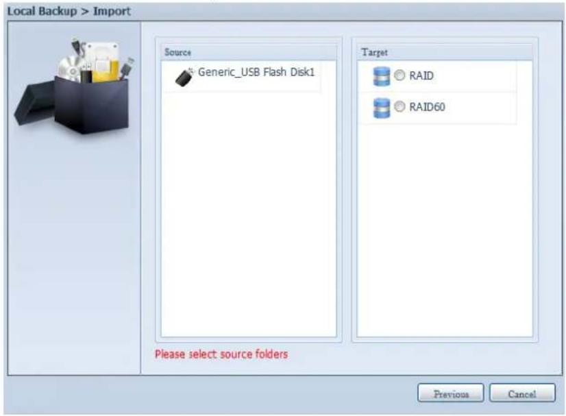
text_image
Local Backup > Import Source Generic_USB Flash Disk1 Target RAID RAID60 Please select source folders Previous CancelClick on the associated external device and the contain folders will be listed. Select the folders that are going to be imported to the NAS and select the available RAID volume which is listed in Target pane.
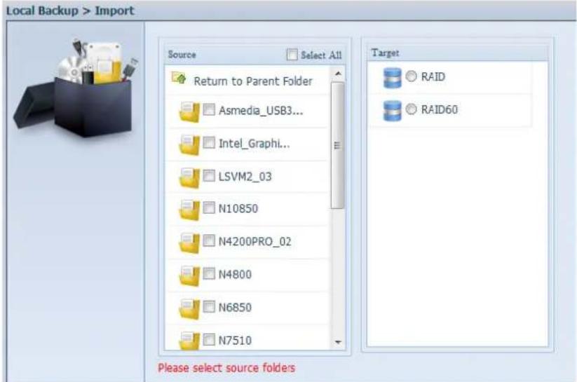
text_image
Local Backup > Import Source Select All Return to Parent Folder Asmedia_USB3... Intel_Graphi... LSVM2_03 N10850 N4200PRO_02 N4800 N6850 N7510 Target RAID RAID60 Please select source foldersIn here, we have selected the "Intel Graphi..." and "N10850" folders from the external device and imported them to the NAS under the RAID60volume.
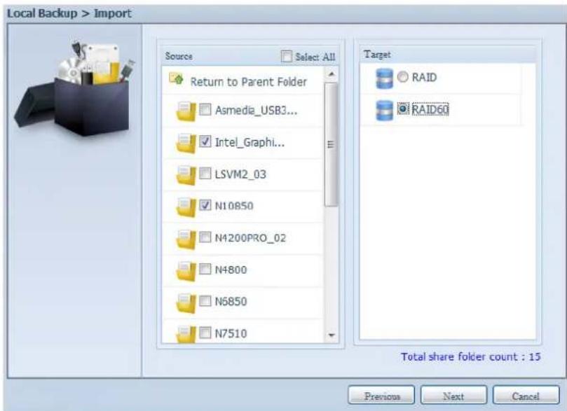
text_image
Local Backup > Import Source Select All Return to Parent Folder Asmedia_USB3... Intel_Graphi... LSVM2_03 N10850 N4200PRO_02 N4800 N6850 N7510 Target RAID RAID60 Total share folder count : 15 Previous Next CancelNext, please select the path from the drop down list to save the log. Also, give the access permission whether these selected folders will be "Public" or not after the import.
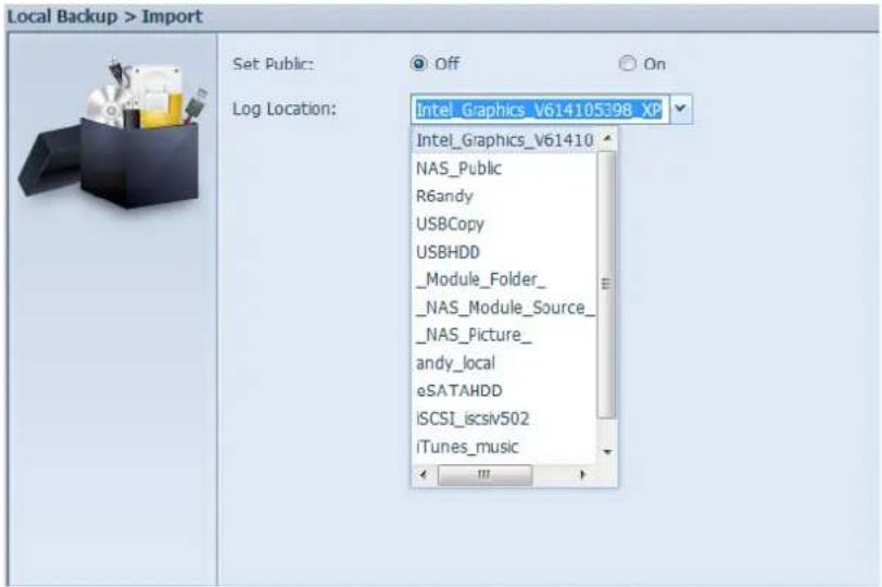
text_image
Local Backup > Import Set Public: Log Location: Intel_Graphics_V614105398_XP Intel_Graphics_V61410 NAS_Public R6andy USBCopy USBHDD _Module_Folder_ _NAS_Module_Source_ _NAS_Picture_ andy_local eSATAHDD iSCSI_icsiv502 iTunes_musicRead the notes and check the "Accept" box for confirmation. If a share name already exists for the import, then the import will be rename automatically to "existing share name -1".
For example, if the NAS RAID volume "RAID60" already has a folder named "Intel_Graphics_V614105398_XP", the import folder will then be rename to: "Intel_Graphics_V614105398_XP-1".
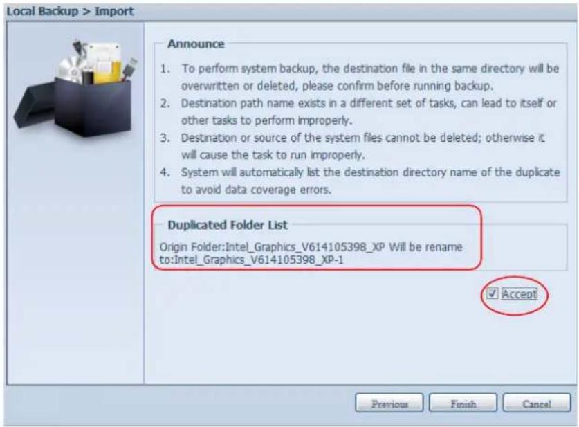
text_image
Local Backup > Import Announce 1. To perform system backup, the destination file in the same directory will be overwritten or deleted, please confirm before running backup. 2. Destination path name exists in a different set of tasks, can lead to itself or other tasks to perform improperly. 3. Destination or source of the system files cannot be deleted; otherwise it will cause the task to run improperly. 4. System will automatically list the destination directory name of the duplicate to avoid data coverage errors. Duplicated Folder List Origin Folder:Intel_Graphics_V614105398_XP Will be rename to:Intel_Graphics_V614105398_XP-1 ✓ Accept Previous Finish CancelNow, you will see in the data guard task list that you have created a task.
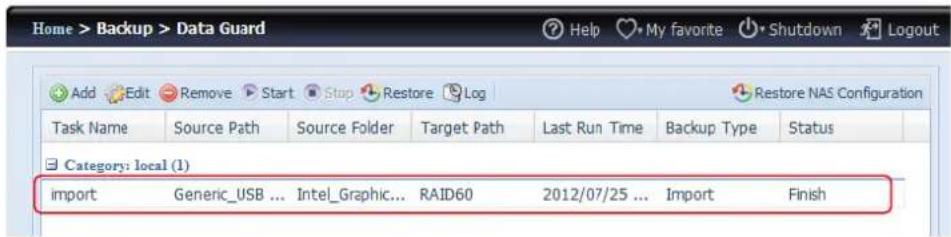
text_image
Home > Backup > Data Guard Add Edit Remove Start Stop Restore Log Task Name Source Path Source Folder Target Path Last Run Time Backup Type Status Category: local (1) import Generic_USB ... Intel_Graphic... RAID60 2012/07/25 ... Import FinishAnd that the system has created 2 new share folders from the task just created.
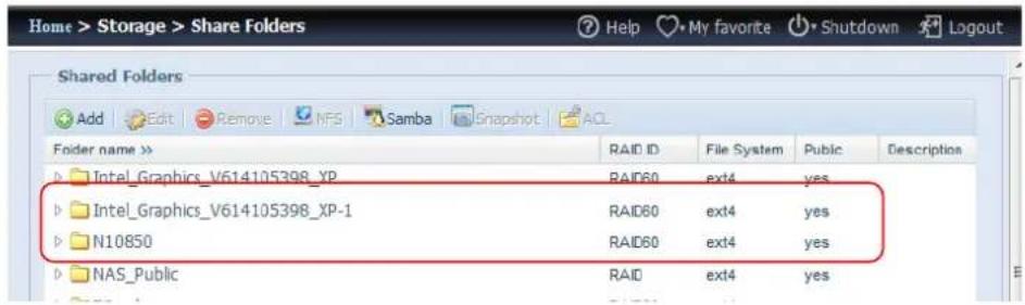
text_image
Home > Storage > Share Folders Add Edit Remove NFS Samba Snapshot ACL Shared Folders Folder name >> Intel_Graphics_V614105398_XP Intel_Graphics_V614105398_XP-1 N10850 NAS_Public RAID ID File System Public Descriptions RAID60 ext4 yes RAID60 ext4 yes RAID60 ext4 yes RAID ext4 yes- Copy: click on "Copy" and this screen appears.
3 different options can be selected, folder to folder, folder to external device or external device to folder.
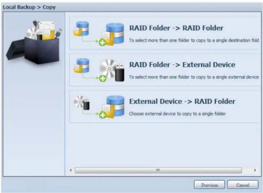
text_image
Local Backup > Copy RAID Folder -> RAID Folder To select more than one folder to copy to a single destination fold RAID Folder -> External Device To select more than one folder to copy to a single external device External Device -> RAID Folder Choose external device to copy to a single folder Previous CancelFolder to Folder
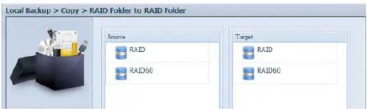
text_image
Local Backup > Copy > RAID Folder to RAID Folder Source RAID RAID50 Target RAID RAID60Folder to external device
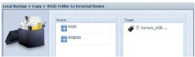
text_image
Local Backup > Copy > RAID Folder to External Device Source RAID RAID60 Target Generic_USB ...External device to Folder
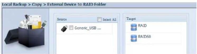
text_image
Local Backup > Copy > External Device to RAID Folder Source Select All Generic_USB ... Target RAID RAID50Let's take "Folder to External device" as an example. In the source pane, select the desired RAID volume and its associated folder list will appear; same method in the target pane for the associated external device.
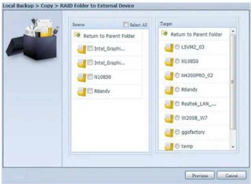
text_image
Local Backup > Copy > RAID Folder to External Device Source Select All Return to Parent Folder Intel_Graphi... Intel_Graphi... N10850 R6andy Target Return to Parent Folder LSVM2_03 N10850 N4200PRO_02 R6andy Realtek_LAN_... W2008_W7 ggofactory temp Previous CancelSelect a folder from the source pane which is going to be copy over, then select in target pane it's destination.
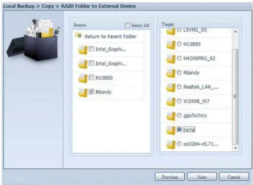
text_image
Local Backup > Copy > RAID Folder to External Device Source Select All Return to Parent Folder Intel_Graphi... Intel_Graphi... N10850 R6andy Target L5VM2_03 N10850 N4200PRO_02 R6andy Realtek_LAN_... W2008_W7 ggofactory tempd xp3264-v5.71... Previous Near CancelChoosing the sync type, "Incremental" or 'Sync', and select the log path from the drop menu list.
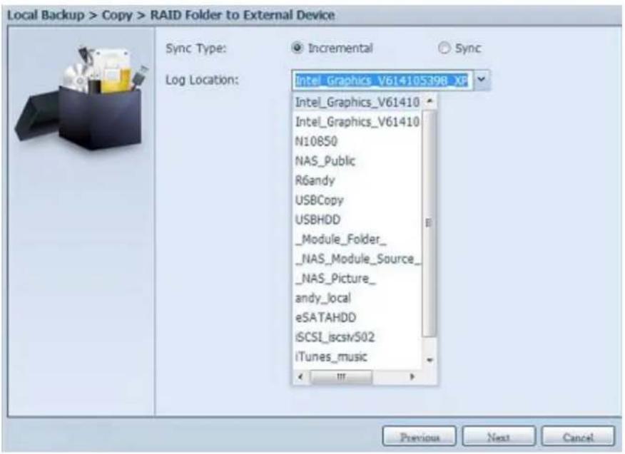
text_image
Local Backup > Copy > RAID Folder to External Device Sync Type: Log Location: Intel_Graphics_V614105398_XP Intel_Graphics_V61410 Intel_Graphics_V61410 N10850 NAS_Public R6andy USBCopy USBHDD _Module_Folder_ _NAS_Module_Source_ _NAS_Picture_ andy_local eSATAHDD iSCSI_iscsv502 iTunes_music Previous Next CancelRead the notes and check the "Accept" box for confirmation.
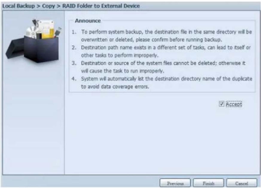
text_image
Local Backup > Copy > RAID Folder to External Device Announce 1. To perform system backup, the destination file in the same directory will be overwritten or deleted, please confirm before running backup. 2. Destination path name exists in a different set of tasks, can lead to itself or other tasks to perform improperly. 3. Destination or source of the system files cannot be deleted; otherwise it will cause the task to run improperly. 4. System will automatically list the destination directory name of the duplicate to avoid data coverage errors. ✓ Accept Previous Finish CancelNow, you will see in the data guard task list that you have created a task.
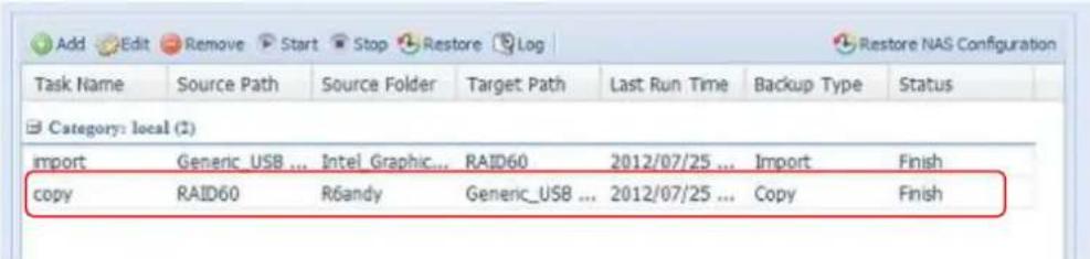
text_image
Add Edit Remove Start Stop Restore Log Task Name Source Path Source Folder Target Path Last Run Time Backup Type Status Category: local (2) import Generic_USB ... IntelGraphic... RAID60 2012/07/25 ... Import Finish copy RAID60 R6andy Generic_USB ... 2012/07/25 ... Copy Finish- Realtime Backup: click on "Realtime Backup" and this screen will appear. 2 different options can be selected from, folder to folder, folder to external device.
Let's take "Folder to Folder" backup for example. Select from the source pane the folder "NAS_Public", then select its destination in the target panefolder "R6andy".
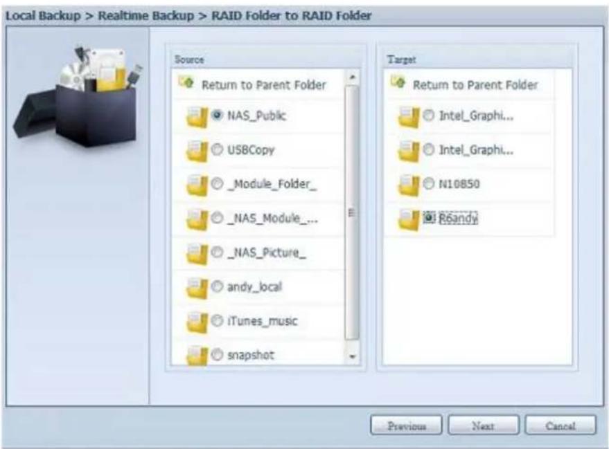
text_image
Local Backup > Realtime Backup > RAID Folder to RAID Folder Source Return to Parent Folder NAS_Public US8Copy _Module_Folder_ NAS_Module_... NAS_Picture_ andy_local iTunes_music snapshot Target Return to Parent Folder Intel_Graphi... Intel_Graphi... N10850 Roandy Previous Next CancelNext, fill in the task name and related settings.
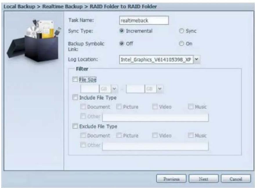
text_image
Local Backup > Realtime Backup > RAID Folder to RAID Folder Task Name: realtimeback Sync Type: Incremental Sync Backup Symbolic Off On Log Location: Intel_Graphics_V614105398_XP Filter File Size GB GB Include File Type Document Picture Video Music Other Exclude File Type Document Picture Video Music Other Previous Next Cancel| Realtime Backup | |
| Item | Description |
| Task Name | Input the task name, length limited to 4~12 characters. |
| Sync Type | Select "Incremental" or "Synchronize". |
| Backup Symbolic Link | Choose to backup symbolic link which is included in the source. |
| Filter | The filter can be set to be executed only in certain circumstances.If none of them has been selected, it will do the real time backup from the source to the destination in full.File size: From xx ~ xxxIf xx=1 and xxx blank then only file size > xx will execute real time backup.If xx=1 and xxx=2 then only size in between xx and will execute real time backup.If xx blank and xxx=2 then only file size < xxx will execute real time backup.Include File Type: Only the associated file format will do the real time backup.Exclude File Type: The excluded file format won't be included in the real time backup.For document file format:doc, xls, pdf, docx, xlsx, txt, ppt, pptx, html, htmFor picture file format:jpg, bmp, tif, png, pbm, tga, xar, xbmFor video file format:avi, mpg, mp4, mkv, fli, flv, rm, ramFor music file format:mp3, wav, wma, acc, dss, msv, dvf, m4p, 3gp, amr, awbUser defined can be input in other box. |
Read the notes and check the "Accept" box for confirmation.
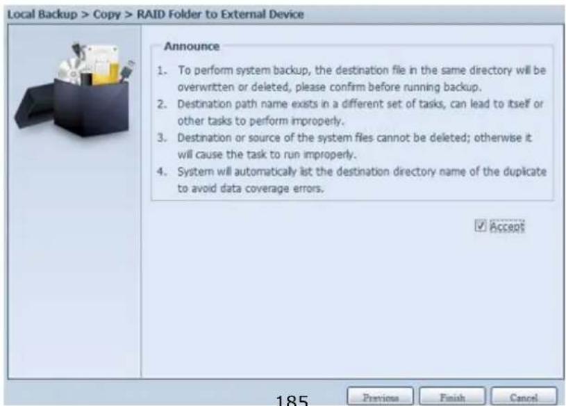
text_image
Local Backup > Copy > RAID Folder to External Device Announce 1. To perform system backup, the destination file in the same directory will be overwritten or deleted, please confirm before running backup. 2. Destination path name exists in a different set of tasks, can lead to itself or other tasks to perform improperly. 3. Destination or source of the system files cannot be deleted; otherwise it will cause the task to run improperly. 4. System will automatically list the destination directory name of the duplicate to avoid data coverage errors. ✓ Accepts Previous Finish Cancel 185Now, you can see in the data guard task list that your created task is listed. The task status will say "Processing" until the "Stop" button is pressed.
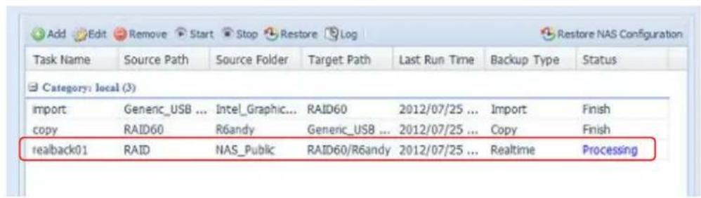
text_image
Add Edit Remove Start Stop Restore Log Task Name Source Path Source Folder Target Path Last Run Time Backup Type Status Category: local (3) import Generic_USB ... Intel_Graphic... RAID60 2012/07/25 ... Import Finish copy RAID60 R6andy Generic_USB ... 2012/07/25 ... Copy Finish realback01 RAID NAS_Public RAID60/R6andy 2012/07/25 ... Realtime Processing- Schedule Backup: click on "Schedule Backup" and this screen will. 2 different choices can be selected from, folder to folder, folder to external device.
Let's use "Folder to External device" backup for our example. From the NAS volume RAID in the Source pane select the folder "NAS_Public", then in the target pane select the external USB disk folder "N10850".
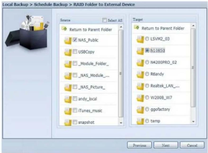
text_image
Local Backup > Schedule Backup > RAID Folder to External Device Source Select All Return to Parent Folder NAS_Public USBCopy _Module_Folder_ NAS_Module_... NAS_Picture_ andy_local iTunes_music snapshot Target Return to Parent Folder LSVM2_03 N10850 N4200PRO_02 R6andy Realtek_LAN_... W2008_W7 ggofactory temp Previous Next CancelNext, fill in the task name and related settings.
| Schedule Backup | |
| Item | Description |
| Task Name | Input the task name, length limited to 4~12 characters. |
| Create Sub-folder | If you choose to create a sub-folder, then it will use the task name as folder name then copy the source under it. Or it will copy the source to the same level as the destination. |
| Sync Type | Select "Incremental" or "Synchronize". |
| Log Location | Select from the drop down list where the task log will be stored. |
| Enable Schedule | Click to enable. If it is not checked, the task won't start unless yo select the associate task and click "Start" from the task list page. |
| Time | Specify the time for the backup to start. |
| Schedule | Can choose daily, weekly or monthly. |
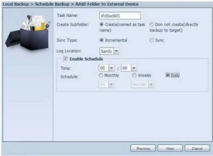
text_image
Local Backup > Schedule Backup > RAID Folder to External Device Task Name: shdback01 Create Subfolder: Create(named as task name) Don not create(directly backup to target) Sync Type: Incremental Sync Log Location: Sandy Enable Schedule Time: 00 : 00 Schedule: Monthly Weekly Daily 00 Monday Previous Next CancelRead the notes and check the "Accept" box for confirmation.
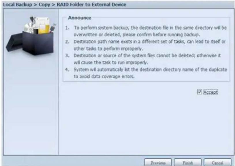
text_image
Local Backup > Copy > RAID Folder to External Device Announce 1. To perform system backup, the destination file in the same directory will be overwritten or deleted, please confirm before running backup. 2. Destination path name exists in a different set of tasks, can lead to itself or other tasks to perform improperly. 3. Destination or source of the system files cannot be deleted; otherwise it will cause the task to run improperly. 4. System will automatically list the destination directory name of the duplicate to avoid data coverage errors. ✓ AccessNow, you will see in the data guard task list that you have created a task.
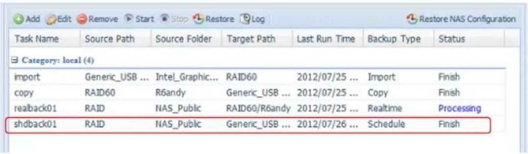
text_image
Add Edit Remove Start Stop Restore Log Restore NAS Configuration Task Name Source Path Source Folder Target Path Last Run Time Backup Type Status Category: local (4) import Generic_USB ... Intel_Graphic... RAID60 2012/07/25 ... Import Finish copy RAID60 R6andy Generic_USB ... 2012/07/25 ... Copy Finish reaback01 RAID NAS_Public RAID60/R6andy 2012/07/25 ... Realtime Processing shdback01 RAID NAS_Public Generic_USB ... 2012/07/26 ... Schedule Finish- iSCSI Backup: click on "iSCSI Backup" and screen appear as below.
It can be backup to two different storage pool, iSCSI to folder, iSCSI to external device.
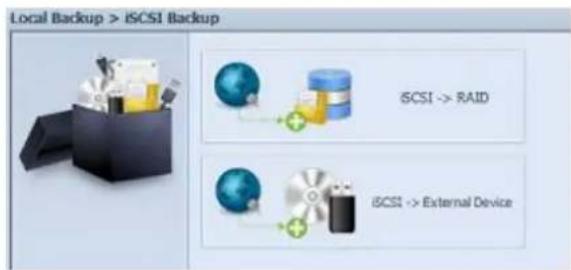
text_image
Local Backup > iSCSI Backup iSCI -> RAID iSCI -> External DeviceLet's take example to have "iSCSI to Folder" backup, from existed iSCSI volume "iSCSI_iscsiv502" to volume RAID folder "andy_local".
The source pane listed "iSCSI_iscsiv502" and "iSCSI_iscsiv50" where are iscsi volume has existed in this system with name "iSCSI_+iscsi target volume name".
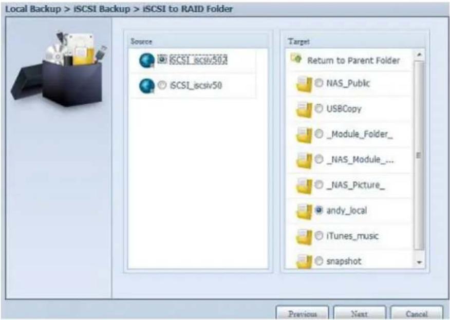
text_image
Local Backup > iSCSI Backup > iSCSI to RAID Folder Source iSCSI_iscsv502 iSCSI_iscsv50 Target Return to Parent Folder NAS_Public USBCopy _Module_Folder_ NAS_Module_... _NAS_Picture_ andy_local iTunes_music snapshot Previous Next CancelNext, provide the task name and where the task log will store.
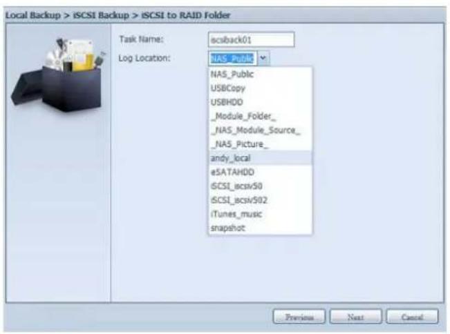
text_image
Local Backup > iSCSI Backup > iSCSI to RAID Folder Task Name: iscisback01 Log Location: NAS_Public NAS_Public USBCopy USBHDD _Module_Folder_ _NAS_Module_Source_ _NAS_Picture_ andy_local eSATAHDD iSCSI_iscsv50 iSCSI_iscsv502 iTunes_music snapshot Previous Next CancelReading the note and check on "Accept" for confirmation.
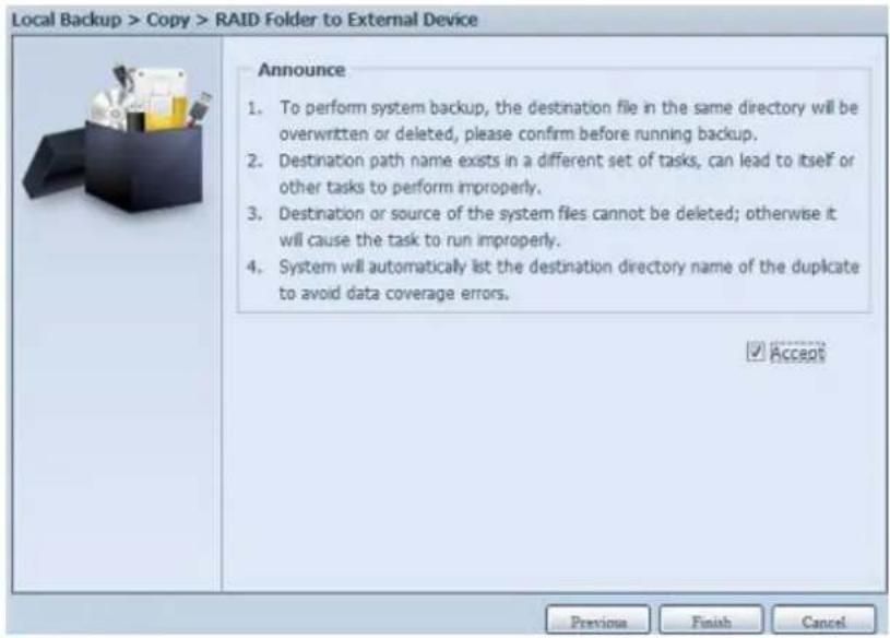
text_image
Local Backup > Copy > RAID Folder to External Device Announce 1. To perform system backup, the destination file in the same directory will be overwritten or deleted, please confirm before running backup. 2. Destination path name exists in a different set of tasks, can lead to itself or other tasks to perform improperly. 3. Destination or source of the system files cannot be deleted; otherwise it will cause the task to run improperly. 4. System will automatically list the destination directory name of the duplicate to avoid data coverage errors. ✓ Accept Previous Finish CancelNow, from the data guard task list will have created task listed. To start the iSCSI volume backup, select the task and click "Start" from task bar.
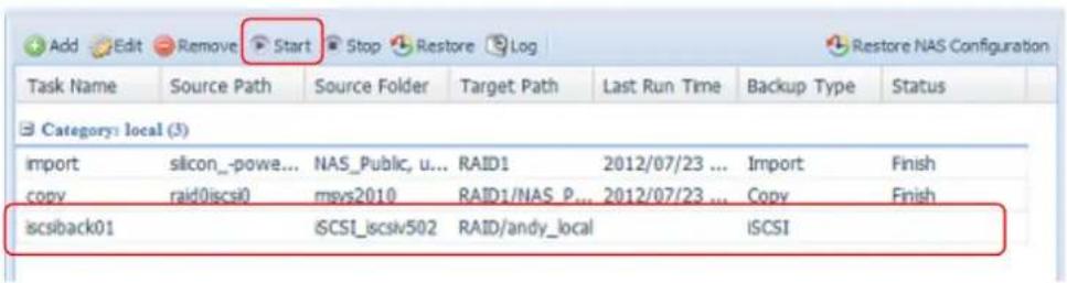
text_image
Add Edit Remove Start Stop Restore Log Restore NAS Configuration Task Name Source Path Source Folder Target Path Last Run Time Backup Type Status Category: local (3) import silicon_-powe... NAS_Public, u... RAID1 2012/07/23 ... Import Finish copy raid0iscsi0 mvs2010 RAID1/NAS P... 2012/07/23 ... Copy Finish iscsiback01 iCSI_iscsiv502 RAID/andy_local iCSIOnce "Start" click, the associated iSCSI volume will not allow to I/O during backup processing. And the task status will change to 'Processing'.
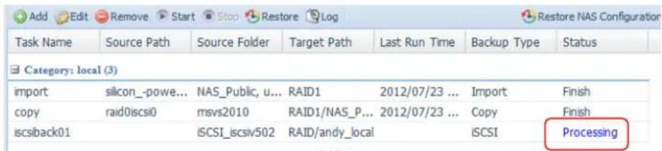
text_image
Add Edit Remove Start Stop Restore Log Task Name Source Path Source Folder Target Path Last Run Time Backup Type Status Category: local (3) import silicon_-powe... NAS_Public, u... RAID1 2012/07/23 ... Import Finish copy raid0iscsi0 msvs2010 RAID1/NAS_P... 2012/07/23 ... Copy Finish iscsback01 iSCSI_iscsiv502 RAID/andy_local iSCSI ProcessingStates change to "Finish" after task complete.
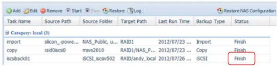
text_image
Add Edit Remove Start Stop Restore Log Restore NAS Configuration Task Name Source Path Source Folder Target Path Last Run Time Backup Type Status Category: local (3) import silicon_-powe... NAS_Public, u... RAID1 2012/07/23 ... Import Finish copy raid0iscsi0 msvs2010 RAID1/NAS_P... 2012/07/23 ... Copy Finish iscsback01 iSCSI_iscsiv502 RAID/andy_local 2012/07/26 ... iSCSI FinishFrom the RAID volume folder 'andy_local', it has backup iSCSI volume file stored. This backup iSCSI volume file is needed while it required import to storage. Next topic will describe about this.

text_image
andy_local on N8900pm (172.16.64.191) File Edit View Favorites Tools Help Back Search Folders Address \\172.16.64.191\andy_local File and Folder Tasks Make a new folder Publish this Web iSCSI_iscsv502 iSCSI_iscsv502 File Edit View Favorites Tools Help Back Search Folders Address \\172.16.64.191\andy_local\iSCSI_iscsv502 File and Folder Tasks Make a new folder Publish this folder to the Web iscsv50201 File 2,097,152 KB- iSCSI Import: click on "iSCSI Import" and screen appear as below. It can be imported from two different storage pools, folder to iSCSI or external device to iSCSI. It is depend on where iSCSI volume has backup to.
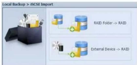
text_image
Local Backup > iSCSI Import RAID Folder -> RAID External Device -> RAIDLet's take example to import "RAID folder to iSCSI" which is the iSCSI volume we have backup earlier to RAID volume folder andy_local than import to volume RAID.
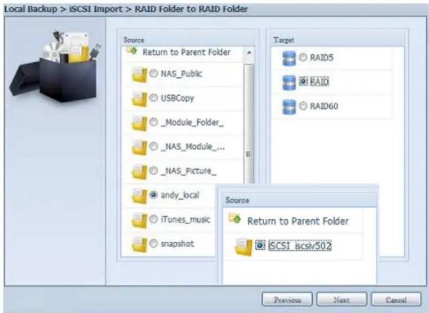
text_image
Local Backup > ISCSI Import > RAID Folder to RAID Folder Source Return to Parent Folder NAS_Public USBCopy _Module_Folder_ NAS_Module_... _NAS_Picture_ andy_local iTunes_music snapshot Target RAID5 RAID RAID60 Source Return to Parent Folder ISCSI_iscsv502 Previous Next CancelNext, provide where the task log will store.
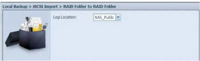
text_image
Local Backup > iSCSI Import > RAID Folder to RAID Folder Log Location: NAS_PublicReading the note and check on "Accept" for confirmation.
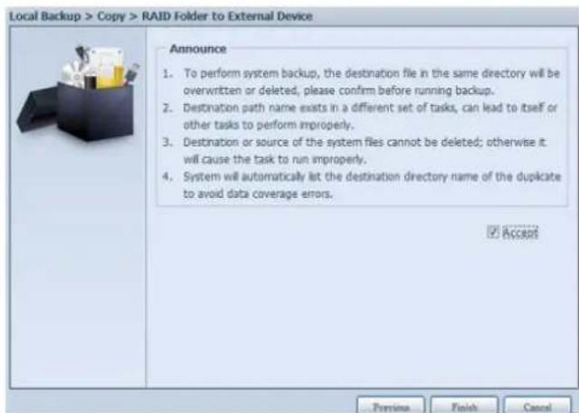
text_image
Local Backup > Copy > RAID Folder to External Device Announce 1. To perform system backup, the destination file in the same directory will be overwritten or deleted, please confirm before running backup. 2. Destination path name exists in a different set of tasks, can lead to itself or other tasks to perform improperly. 3. Destination or source of the system files cannot be deleted; otherwise it will cause the task to run improperly. 4. System will automatically let the destination directory name of the duplicate to avoid data coverage errors. ✓ AccessNow, from the data guard task list will have created task listed.
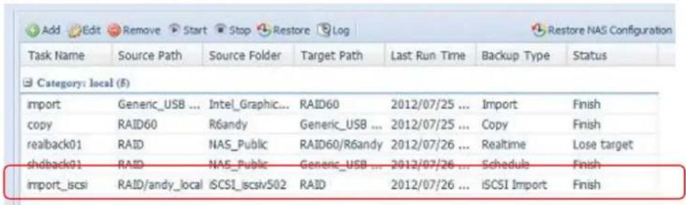
text_image
Add Edit Remove Start Stop Restore Log Restore NAS Configuration Task Name Source Path Source Folder Target Path Last Run Time Backup Type Status Category: local (F) import Generic_USB ... Intel_Graphic... RAID60 2012/07/25 ... Import Finish copy RAID60 R6andy Generic_USB ... 2012/07/25 ... Copy Finish realback01 RAID NAS_Public RAID60/R6andy 2012/07/26 ... Realtime Lose target shdback01 RAID NAS_Public Generic_USB ... 2012/07/26 ... Schedule Finish import_iscsi RAID/andy_local iCSI_iscsiv502 RAID 2012/07/26 ... iCSI Import FinishUSB Copy
The USB Copy function using the USB copy button or front panel LCM/OLED of system used to only offer one-way transfers (i.e. only from the USB drive to the designated NAS folder). Now numerous options are available, such as: Disabled, bi-directional, and scheduled.
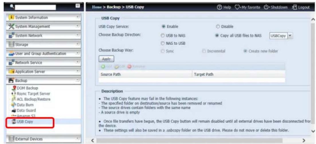
text_image
Home > Backup > USB Copy System Information System Management System Network Storage User and Group Authentication Network Service Application Server Backup DOM Backup Rsync Target Server ACL Backup/Restore Data Burn Data Guard Amazon S3 USB Copy External Devices USB Copy USB Copy Service: Enable Disable Choose Backup Direction: USB to NAS Copy all USB files to NAS USBCopy NAS to USB Choose Backup Way: Sync Incremental Create new folder Apply Add Edit Replace Source Path Target Path Description The USB Copy feature may fail in the following instances: - The specified folder on destination/source has been removed or renamed - The source drives contain folders with the same name - A source drive is empty Once file transfers have begun, the USB Copy button will remain disabled until all external drives have been disconnected from the device. These settings will also be saved in a .usbcopy folder on the USB drive. Please do not move or delete this folder.Disable USB Copy
Simply select "Disable" for the USB Copy Service option and the USB Copy button or LCM/OLED USB Copy item will become inactive.
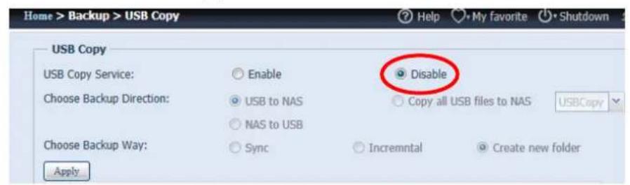
text_image
Home > Backup > USB Copy USB Copy USB Copy Service: ○ Enable Choose Backup Direction: ○ USB to NAS ○ NAS to USB Choose Backup Way: ○ Sync Apply Disable ○ Copy all USB files to NAS USBCopy ○ Incremental ○ Create new folderUsing USB Copy
Enable the USB Copy service and select one of the 3 options available: "USB to NAS", "NAS to USB", and "Copy all USB files to NAS".
If select "USB to NAS" or "NAS to NAS", you will also need to set up the type of backup desired.
| USB Copy Service Transfer Opons | |
| Item | Descripon |
| Sync | Makes your source match your target completely; deleng and adding les on your target as they are deleted and added on your source. |
| Incremental | Makes your source match your target and keep all old les; adding les on your target as they are added on your source, but NOT deleng les on your target as they are deleted on your source. |
| Create New Folder | Create new folder on target based on the task’s “Date+Time”. |
| Apply | Press Apply to conrm the sengs. |
Now, add the task for the USB Copy service you have selected (for "USB to NAS" or "NAS to USB").
Click on "Add" and select "Source Path" and "Target Path" from the drop-down list.

text_image
Add Edit Remove Source Path Target PathAdd Source:
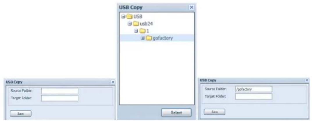
text_image
USB Copy Source Folder: Target Folder: Size Select USB Copy USB usb24 1 gofactory USB Copy Source Folder: /gofactory Target Folder:Add Target:
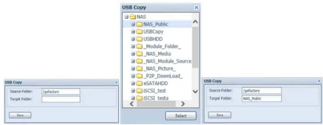
text_image
USB Copy Source Folder: /gofactory Target Folder:Save the completed task:

text_image
Add Edit Remove Source Path Target Path /gofactory NAS_PublicTo "Edit" or "Remove" a USB Copy task, select the task item and click on the associated function:

text_image
Add Edit Remove Source Path Target Path _NAS_Module_Source_ usb:// _NAS_Picture_ /gofactoryIf you select "Copy all USB files to NAS", then please choose the target path from the drop-down list. All files and folders on the USB device will be copied over to the NAS.

text_image
Choose Backup Direction: USB to NAS Copy all USB files to NAS USBCopy SNAP NAS to USB Choose Backup Way: Sync Incremental Create new NAS_Public Apply iTunes_musicNOTE
If "Sync" mode has been selected, the target-side redundant folders/files will be deleted after a comparison has been conducted of the source.
NOTE
Once the USB Copy service has completed, the USB device will un-mount from system. To start another task, please re-insert the USB device.
Volume Expansion Management
The user guide please refers to URL below.
http://www.thecus.com/download/manual/AllinOne_64bit/Volume_Expansion_v1.0.pdf
Thecus Backup Utility
The Thecus Backup Utility is on your Installation CD. When you click on the CD, the Backup Utility will be installed under Program Groups > Thecus > Thecus Backup Utility. If it is not installed, you can copy the file (Thecus Backup Utility.exe) to a convenient location on your hard disk and double click to execute it.

Thecus Backup.exe
NOTE
If you can not find Thecus Backup Utility on your CD, please download it from the Thecus website (http://www.thecus.com).
When you execute this utility for the first time, it will ask you to create a DB file. Click Yes.
- Click Add to create a Backup task. The Add New Task dialog box will appear.
| Add New Task | |
| Item | Description |
| Task | Specifies a name for the current task. |
| Source | Click to specify the source folder/file location. |
| Incremental | Click to specify whether the backup will be incremental.If unchecked, the backup will be a full backup. |
| Destination | Click to specify the destination folder/file location. |
| Excluded extensions | Files with these file name extensions will be skipped and not backed up to the destination. |
| Comments | If you wish, enter a comment here for your records. |
-
To schedule the task to run at regular intervals, click on the Schedule icon for that task. You can schedule the task to run Monthly or Weekly.
-
To check the log for that task, click on the Log icon for that task.
NOTE
Thecus Backup Utility also supports MAC OS X. Just copy the Thecus Backup Utility.dmg to your MAC OS X machine and double click to execute it.
Windows XP Data Backup
If you use Windows XP Professional, you can also use the Windows Backup Utility (Ntbackup.exe) to back up your files.
If you use Windows XP Home Edition, follow these steps to install the utility:
-
Insert the Windows XP CD into a drive and double-click the CD icon in My Computer.
-
When the Welcome to Microsoft Windows XP screen appears, click Perform Additional Tasks.
- Click Browse this CD.
- In Windows Explorer, navigate to ValueAdd > Msft > Ntbackup.
- Double-click Ntbackup.msi to install the backup utility.
Once installed, you can use the Windows Backup Utility by following the steps below:
- Click Start, and point to All Programs > Accessories > System Tools > Backup to start the wizard.
- Click Next to skip past the opening page. Choose Backup files and settings from the second page, and then click Next.
- Select which option you want to back up.
- Click Next and in the Backup Type, Destination, and Name page, specify a backup location using the Browse button.
- Find and select the drive that specifies your Thecus IP storage as your backup destination and click Next.
- Click Next to display the wizard's final page and click Finish to start backing up.
Apple OS X Backup Utilities
Mac OS X does not include any backup software. However, there are a number of backup solutions available for the Mac OS X, including: iBackup, Psyncx, iMSafe, Rsyncx, Folder Synchronizer X, Tri-BACKUP, Impression, Intego Personal Backup, SilverKeeper, and Apple's dotMac Backup utility to name just a few. To find even more freeware and shareware backup utilities to choose from, go to VersionTracker or MacUpdate and search on "backup".
External Devices
The Thecus IP storage supports printer server and UPS via USB interface. The integrated Print Server allows you to share a single USB printer with all users on the network. For the UPS, Thecus IP storage support via USB, Series and Network interface. The following section shows you how.
Printers
From the External Devices menu, choose the Printer item, and the Printer Information screen appears. This screen provides the following information about the USB printer connected to the USB port.
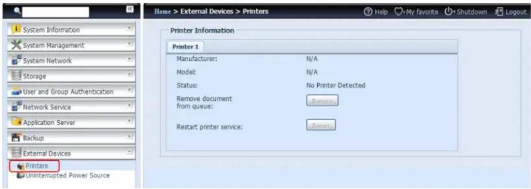
text_image
Home > External Devices > Printers System Information System Management System Network Storage User and Group Authentication Network Service Application Server Backup External Devices Printers Uninterrupted Power Source Printer Information Printer 1 Manufacturer: N/A Model: N/A Status: No Printer Detected Remove document from queue: Restart printer service:| Printer Information | |
| Item | Description |
| Manufacturer | Displays the name of the USB printer manufacturer. |
| Model | Displays the model of the USB printer. |
| Status | Displays the status of the USB printer. |
| Remove document from Queue | Click to remove all documents from printer queue |
| Restart Printer service | Click to restart printer service |
If a corrupt print job is sent to a printer, printing may suddenly fail. If your print jobs seem to be locked up, pressing the Remove All Documents button to clear the print queue may resolve the issue.
You can configure Thecus IP storage to act as a printer server. That way, all PCs connected to the network can utilize the same printer.
Windows XP SP2
To set up the Printer Server in Windows XP SP2, follow the steps below:
-
Connect the USB printer to one of the USB ports (preferably the rear USB ports; front USB ports can be used for external HDD enclosures).
-
Go to Start > Printers and Faxes.
-
Click on File > Add Printer.
-
The Add Printer Wizard appears on your screen. Click Next.
-
Select the "A network printer, or a printer attached to another computer" option.
-
Select "Connect to a printer on the Internet or on a home or office network", and enter "http://Thecus IP storage IP_ADDRESS:631/printers/usb-printer" into the URL field.
-
Your Windows system will ask you to install drivers for your printer. Select the correct driver for your printer.
-
Your Windows system will ask you if you want to set this printer as "Default Printer". Select Yes and all your print jobs will be submitted to this printer by default. Click Next.
9. Click Finish.
NOTE
- Note that if a multi-function (all-in-one) printer is attached to the Thecus IP Storage, usually only the printing and fax functions will work. Other features, such as scanning, will probably not function.
Windows Vista
To set up the Printer Server in Windows Vista, follow the steps below:
1. Open Printer Folder from the Control Panel.
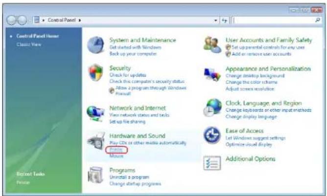
text_image
Control Panel Home Classic View System and Maintenance Get started with Windows Back up your computer Security Check for updates Check this computer's security status Allow a program through Windows Firewall Network and Internet View network status and tests Set up file sharing Hardware and Sound Play CDs or other media automatically Features Mouse Programs Uninstall a program Change startup programs User Accounts and Family Safety Set up parental controls for any user Add or remove user accounts Appearance and Personalization Change desktop background Change the color scheme Adjust screen resolution Clock, Language, and Region Change keyboards or other input methods Change display language Ease of Access Let Windows suggest settings Optimize visual display Additional Options2. Click the right mouse button in anywhere on the Printers folder and then select Add Printer.
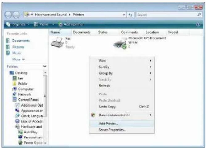
text_image
Hardware and Sound Printers Organize Views Add a printer/ Favorite Links Documents Pictures Music More > Folders Desktop file Public Computer Network Control Panel Additional Opt Appearance or Clock, Language... Ease of Access Hardware and AutoPlay Personalizati Power Optio Name Documents Status Comments Location Model Fax 0 Ready Microsoft XPS Document Writer View Sort By Group By Stack By Refresh Paste Paste Shortcut Undo Copy Ctrl+Z_ Run as administrator Add Printer... Server Properties...- Select Add a network, wireless or Bluetooth printer.
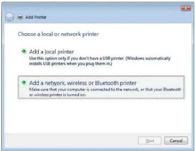
text_image
Add Printer Choose a local or network printer → Add a local printer Use this option only if you don't have a USB printer. (Windows automatically installs USB printers when you plug them in.) → Add a network, wireless or Bluetooth printer Make sure that your computer is connected to the network, or that your Bluetooth or wireless printer is turned on. Next Cancel- Select The printer that I want isn't listed.
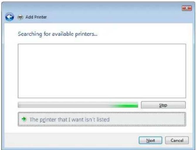
text_image
Add Printer Searching for available printers... Stop The printer that I want isn't listed Next CancelYou can press The printer that I want isn't listed to go into next page without waiting for Searching for available printers to finish.
- Click Select a shared printer by name.
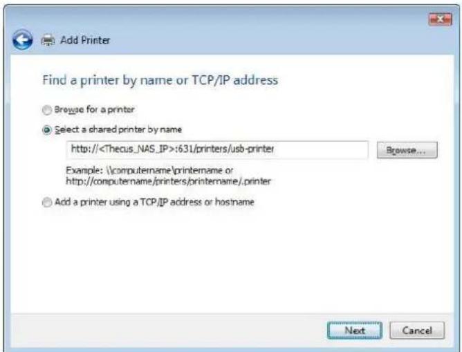
text_image
Add Printer Find a printer by name or TCP/IP address Browse for a printer Select a shared printer by name http://Type http://
- Select or install a printer and then press OK.
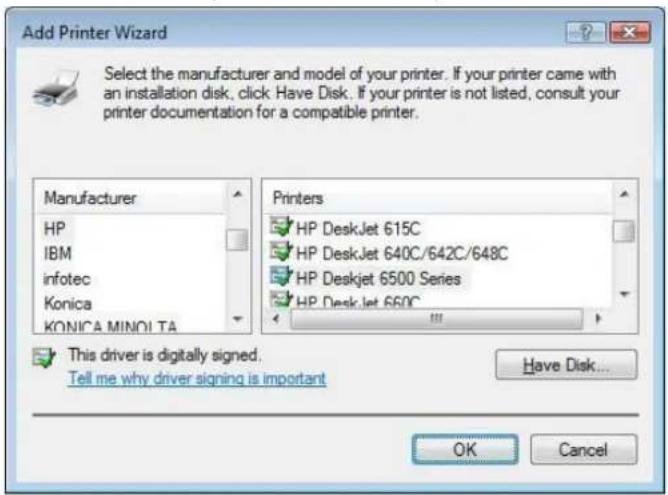
text_image
Add Printer Wizard Select the manufacturer and model of your printer. If your printer came with an installation disk, click Have Disk. If your printer is not listed, consult your printer documentation for a compatible printer. Manufacturer HP IBM infotec Konica KONICA MINOLTA Printers HP DeskJet 615C HP DeskJet 640C/642C/648C HP Deskjet 6500 Series HP DeskJet 660C This driver is digitally signed. Tell me why driver signing is important Have Disk... OK Cancel- Windows will attempt to connect to the printer.
text_image
Windows Printer Installation Connecting to http://172.16.66.64:631/printers/usb-printer Cancel- You can choose to set this printer as the default printer by checking the Set as the default printer box. Click Next to continue.
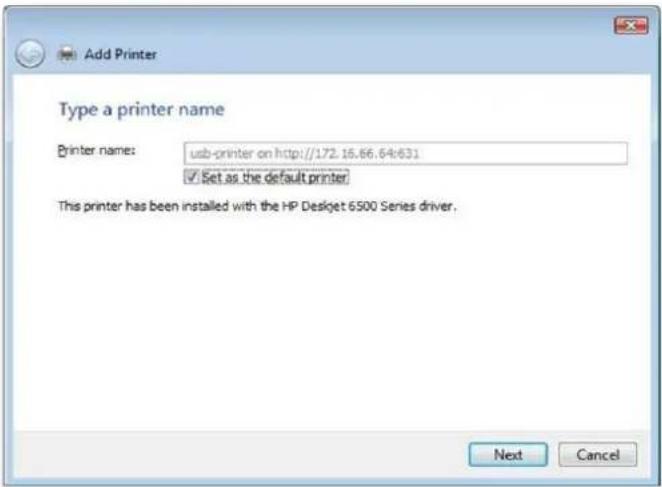
text_image
Add Printer Type a printer name Printer name: usb-printer on http://172.16.66.64:631 ✓ Set as the default printer This printer has been installed with the HP Deskjet 6500 Series driver. Next Cancel- Done! Click Finish.
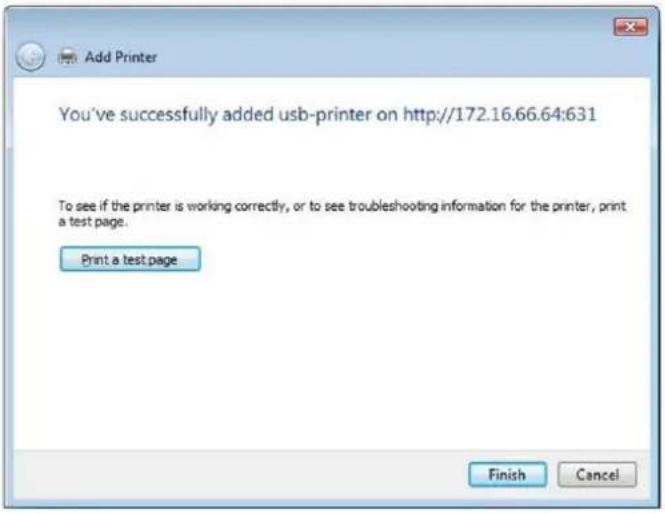
text_image
Add Printer You've successfully added usb-printer on http://172.16.66.64:631 To see if the printer is working correctly, or to see troubleshooting information for the printer, print a test page. Print a test page Finish CancelUninterrupted Power Source
From the External Devices menu, choose the Uninterrupted Power Source item and the UPS Setting screen appears. Make any changes you wish, and press Apply to confirm changes.
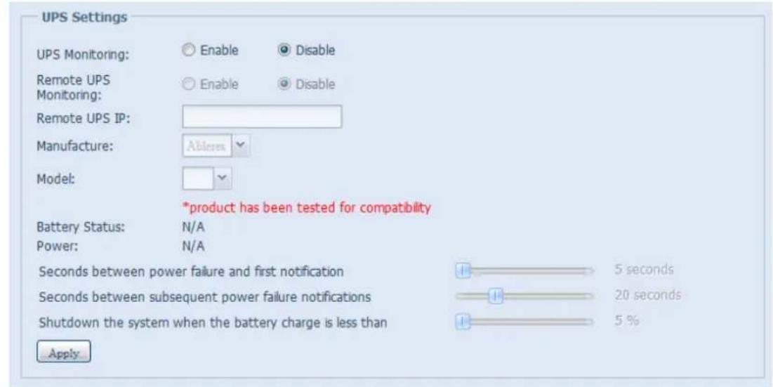
text_image
UPS Settings UPS Monitoring: Enable Disable Remote UPS Monitoring: Enable Disable Remote UPS IP: Manufacture: Ablers Model: *product has been tested for compatibility Battery Status: N/A Power: N/A Seconds between power failure and first notification 5 seconds Seconds between subsequent power failure notifications 20 seconds Shutdown the system when the battery charge is less than 5 % ApplySee the following table for a detailed description of each item.
| UPS Setting | |
| Item | Description |
| UPS Monitoring | Enable or disable UPS monitoring. |
| Remote UPS Monitoring | Enable or disable Remote UPS monitoring. |
| Remote UPS IP | Input the IP address of the NAS that the UPS device is connected to via USB or RS232.Input the IP address of your network UPS. |
| Manufacturer | Choose the UPS manufacturer from the dropdowns. |
| Model | Choose the UPS model number from the dropdowns. |
| Battery Status | Current status of the UPS battery |
| Power | Current status of the power being supplied to the UPS |
| Seconds between power failure and first notification | Delay between power failure and first notification in seconds. |
| Seconds between subsequent power failure notifications | Delay between subsequent notifications in seconds. |
| Shutdown the system when the battery charge is less than | Amount of UPS battery remaining before system should auto-shutdown. |
| Apply | Press Apply to save your changes. |
Chapter 5: Tips and Tricks
USB and eSATA Storage Expansion
The Thecus IP storage supports external USB hard disks through its USB ports. Once a USB hard disk is successfully mounted, the entire volume will be linked automatically to the default USB HDD folder. The Thecus IP storage supports USB external storage devices. All file names on the USB disk volume are case sensitive.
The Thecus IP storage also supports eSATA hard disks with its eSATA port.
Before attaching an eSATA or USB disk drive to Thecus IP storage, you have to partition and format it on a desktop computer or a notebook first. The attached device will be located at \192.168.1.100\usbhdd\sd(x)1 where 192.168.1.100 means the IP address of Thecus IP storage and sd(x)1 stands for the first partition on the eSATA or USB disk drive.
Remote Administration
You can set up your Thecus IP storage for remote administration. With remote administration, you can access your Thecus IP storage over the Internet, even if your Thecus IP storage is behind a router. This is especially useful if you are traveling and suddenly need a file from your Thecus IP storage.
Setting up remote administration is a three-part process, and will require the following equipment:
• Thecus IP storage device
- Cable / DSL Router with Dynamic DNS support
- Home PC
- Internet Connection
NOTE
Router setup will differ slightly depending on router used. For this example, we will use the Asus WL500g because it has support for Dynamic DNS. Contact your router hardware vendor for setup help.
Part I - Setup a DynDNS Account
- Go to http://www.dyndns.org from your home PC.
- Click on the Sign Up Now link.
- Check the Check boxes, select a user name (i.e.: N12000), enter your email address (i.e.: xxx@example.com), check Enable Wildcard, and create a password (i.e.: xxxx).
- Wait for an email from www.dyndns.org.
- Open the email and click on the link to activate your account
Part II - Enable DDNS on the Router
- Go to the router setup screen and select IP Config > Miscellaneous DDNS Setting from your Home PC.
- Click on Yes for Enable the DDNS Client?
- Select www.dyndns.org.
- Go to router setup screen, and enter the following information:
a. User Name or E-mail Address: xxx@example.com
b. Password or DDNS Key: xxxx
c. Host Name: www.N12000.dyndns.org
d. Enable wildcard? Select Yes
e. Update Manually: Click Update
Part III - Setting up Virtual Servers (HTTPS)
- Navigate to NAT Setting > Virtual Server.
- For Enable Virtual Server?, select Yes
- Setup the HTTPS Server
a. Well-Known Applications: Select User Defined
b. Local IP: Enter 192.168.1.100
c. Port Range: 443 (the default HTTPS port setting on the Thecus IP storage)
d. Protocol: select TCP
e. Click Add.
f. Click Apply.
- Test the HTTPS connection from another computer on the Internet
a. From a remote computer, open your browser and enter https://www.N12000.dyndns.org
b. You should see the login page of Thecus IP storage.
Firewall Software Configuration
If you are using a software firewall (i.e. Norton Internet Security) and are having trouble connecting to Thecus IP storage, you can try the following steps:
- Double click the NIS icon on system tray, and then configure the Personal Firewall.
- On the Programs page, find the SetupWizard.exe and change its permission to "Permit All". If it's not in the program list, use the Add or Program Scan buttons to find it.
- On the Networking page, manually add Thecus IP storage IP address (i.e. 192.168.1.100) to the Trusted list.
Replacing Damaged Hard Drives
If you are using RAID 1, RAID 5, RAID 6, RAID 50 or RAID 60 you can easily replace a damaged hard drive in the Thecus IP storage while keeping your data secure with the system's automatic data recovery.
Hard Drive Damage
When a hard drive is damaged and data in the RAID volume is corrupted, the system OLED will display a warning message and the system will beep.
Replacing a Hard Drive
To replace a hard disk drive in the Thecus IP storage:
- Remove the tray with the damaged hard disk.
- Unscrew the damaged hard disk and remove it from the tray.
- Slide a new hard disk into the tray and fasten the screws.
- Insert the hard disk tray back into the Thecus IP storage until it snaps into place. You can also lock it with a key if desired.
- The LED will blink green when the HDD is accessed.
RAID Auto-Rebuild
When using RAID 1, 5, 6, 10, 50 or 60 on the Thecus IP storage, you can use the auto-rebuild function when an error is detected.
- When a hard disk fails the system beeps and/or an email notification is sent to the specified receivers.
- Check the OLED to see which disk has failed.
- Follow the steps mentioned above to replace the failed hard disk.
- The system automatically recognizes the new hard disk and starts the auto-rebuild sequence to resume its status before the hard disk crash.
Chapter 6: Troubleshooting
Forgot My Network IP Address
If you forget your network IP address and have no physical access to the system, you can find out the IP address by either looking directly onto the Thecus IP storage OLED panel, or by using the setup wizard to retrieve the IP of your Thecus IP storage.
- Start the Setup Wizard, and it will automatically detect all Thecus IP storage products on your network.
- You should be able to find the IP address of the Thecus IP storage which you have forgotten in the Device Discovery screen.
Can't Map a Network Drive in Windows XP
You may have problems mapping a network drive under the following conditions:
- The network folder is currently mapped using a different user name and password. To connect using a different user name and password, first disconnect any existing mappings to this network share.
- The mapped network drive could not be created because the following error has occurred: Multiple connections to a server or shared resource by the same user, using more than one user name, are not allowed. Disconnect all previous connections to the server or shared resource and try again.
To check out existing network connections, type net use under the DOS prompt. You may refer the URL below for more network mapping information.
hp://esupport.thecus.com/support/index.php?_m=downloads&_a=viewdownload&downloaditemid=57&nav=0
Restoring Factory Defaults
From the System menu, choose the Factory Default item and the Reset to Factory Default screen appears. Press Apply to reset Thecus IP storage factory default settings.
WARNING
Resetting to factory defaults will not erase the data stored in the hard disks, but WILL revert all the settings to the factory default values.
Problems with Time and Date Settings
The administrator is able to select an NTP Server to keep Thecus IP storage time synchronized. However, if Thecus IP storage cannot access the Internet, you may encounter a problem when setting the Time and Time Zone. If this happens:
- Login to the Web Administration Interface.
- Navigate to System Management>Time.
- Under NTP Server, select No.
- Set the Date, Time, and Time Zone.
- Click Apply.
In addition, if the Thecus IP storage is able to access the Internet and you want to keep the NTP Server clock.isc.org by default, please make sure the DNS Server is correctly entered, thereby allowing the NTP Server name to correctly resolve. (See System Network > WAN/LAN1 > DNS Server)
Dual DOM Supports for Dual Protection (N12000 series/N16000 series/N8900 series only)
The most advance and useful feature on the Thecus IP storage (depend on models) is the implemented Dual DOM. Under normal circumstances, there is no need to have this feature involved. But some unpredictable problems like power cut or human error can occur by accident, especially during system booting stage; the Dual Dom will become the best feature to prevent system down time. Practically while it happened, system will try to recover the DOM 1 from DOM 2 first. If it is unachievable then the system can boot from DOM 2. And all of these procedures can be operated through the OLED.
NOTE
The DOM1 in Dual DOM is by default the master DOM and FW updates will only apply to DOM1. DOM2 is 'Read only'.
If anything happened and the DOM1 is recovered from DOM2, the FW version will be the one of the DOM2. Therefore, it may need to be upgraded to the version of DOM1.
If DOM1 can not be recovered from DOM2, the system will boot up from DOM2. The original configuration of DOM1 may need to be setup again with DOM2 operations.
Appendix A: Customer Support
If your Thecus IP storage is not working properly, we encourage you to check out Chapter 6: Troubleshooting, located in this manual. You can also try to ensure that you are using the latest firmware version for your Thecus IP storage. Thecus is committed to providing free firmware upgrades to our customers. Our newest firmware is available on our Download Center:
http://www.thecus.com/sp_download.php
If you are still experiencing problems with your Thecus IP storage, or require a Return Merchandise Authorization (RMA), feel free to contact technical support via our Technical Support Website:
http://www.thecus.com/sp_tech.php
Customers in the US should send all technical support enquiries to the US contact window included in the following web page:
http://www.thecus.com/sp_tech.php
For Sales Information you can e-mail us at:
sales@thecus.com
Thank you for choosing Thecus!
Appendix B: RAID Basics
Overview
A Redundant Array of Independent Disks (RAID) is an array of several hard disks that provide data security and high performance. A RAID system accesses several hard disks simultaneously, which improves I/O performance over a single hard disk. Data security is enhanced by a RAID, since data loss due to a hard disk failure is minimized by regenerating redundant data from the other RAID hard disks.
Benefits
RAID improves I/O performance, and increases data security through fault tolerance and redundant data storage.
Improved Performance
RAID provides access to several hard disk drives simultaneously, which greatly increases I/O performance.
Data Security
Hard disk drive failure unfortunately is a common occurrence. A RAID helps prevent against the loss of data due to hard disk failure. A RAID offers additional hard disk drives that can avert data loss from a hard disk drive failure. If a hard drive fails, the RAID volume can regenerate data from the data and parity stored on its other hard disk drives.
RAID Levels
The Thecus IP storage supports standard RAID levels 0, 1, 5, 6, 10, 50, 60 and JBOD. You choose a RAID level when you create a system volume. The factors for selecting a RAID level are:
- Your requirements for performance
- Your need for data security
- Number of hard disk drives in the system, capacity of hard disk drives in the system
The following is a description of each RAID level:
RAID 0
RAID 0 is best suited for applications that need high bandwidth but do not require a high level of data security. The RAID 0 level provides the best performance of all the RAID levels, but it does not provide data redundancy.
RAID 0 uses disk striping and breaking up data into blocks to write across all hard drives in the volume. The system can then use multiple hard drives for faster read and write. The stripe size parameter that was set when the RAID was created determines the size of each block. No parity calculations complicate the write operation.
RAID 1
RAID 1 mirrors all data from one hard disk drive to a second one hard disk drive, thus providing complete data redundancy. However, the cost of data storage capacity is doubled.
This is excellent for complete data security.
RAID 5
RAID 5 offers data security and it is best suited for networks that perform many small I/O transactions at the same time, as well as applications that require data security such as office automation and online customer service. Use it also for applications with high read requests but low write requests.
RAID 5 includes disk striping at the byte level and parity information is written to several hard disk drives. If a hard disk fails the system uses parity stored on each of the other hard disks to recreate all missing information.
RAID 6
RAID 6 is essentially an extension of RAID level 5 which allows for additional fault tolerance by using a second independent distributed parity scheme (dual parity). Data is striped on a block level across a set of drives, just like in RAID 5, and a second set of parity is calculated and written across all the drives; RAID 6 provides for an extremely high data fault tolerance and can sustain two simultaneous drive failures.
This is a perfect solution for mission critical applications.
RAID 10
RAID 10 is implemented as a striped array whose segments are RAID 1 arrays.
RAID 10 has the same fault tolerance as RAID level 1.
RAID 10 has the same overhead for fault-tolerance as mirroring alone. High I/O rates are achieved by striping RAID 1 segments.
Under certain circumstances, RAID 10 array can sustain up to 2 simultaneous drive failures
Excellent solution for applications that would have otherwise gone with RAID 1 but need an additional performance boost.
RAID 50
A RAID 50 combines the straight block-level striping of RAID 0 with the distributed parity of RAID 5. This is a RAID 0 array striped across RAID 5 elements. It requires at least 6 drives.
RAID 60
A RAID 60 combines the straight block-level striping of RAID 0 with the distributed double parity of RAID 6. That is, a RAID 0 array striped across RAID 6 elements. It requires at least 8 disks.
JBOD
Although a concatenation of disks (also called JBOD, or "Just a Bunch of Disks") is not one of the numbered RAID levels, it is a popular method for combining multiple physical disk drives into a single virtual one. As the name implies, disks are merely concatenated together, end to beginning, so they appear to be a single large disk.
As the data on JBOD is not protected, one drive failure could result total data loss.
Stripe Size
The length of the data segments being written across multiple hard disks. Data is written in stripes across the multiple hard disks of a RAID. Since multiple disks are accessed at the same time, disk striping enhances performance. The stripes can vary in size.
Disk Usage
When all disks are of the same size, and used in RAID, Thecus IP storage disk usage percentage is listed below:
| RAID Level | Percentage Used |
| RAID 0 | 100% |
| RAID 1 | 1/n × 100% |
| RAID 5 | (n-1)/n × 100% |
| RAID 6 | (n-2)/n × 100% |
| RAID 10 | 50% |
| RAID 50 | (n-1)/n × 100% |
| RAID 60 | (n-2)/n × 100% |
| JBOD | 100% |
n : HDD number
Appendix C: How to open the top cover
N8900 series:
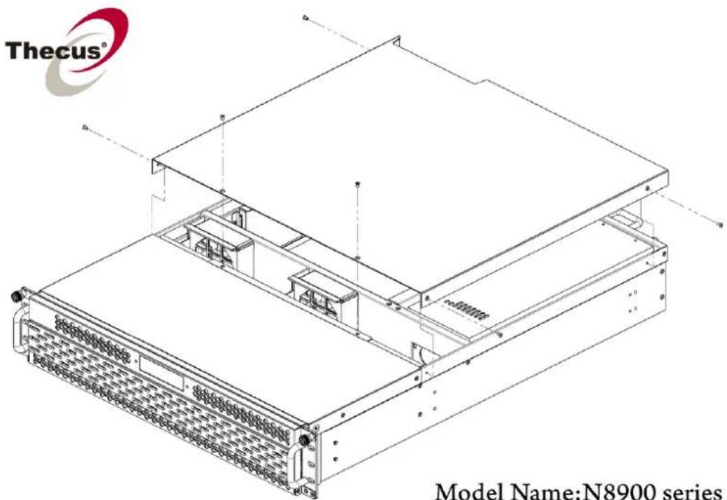
text_image
Thecus® Model Name:N8900 seriesModel Name:N8900 series
N12000 series:
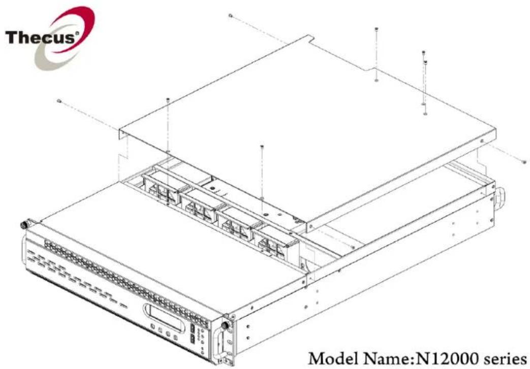
text_image
Thecus® Model Name:N12000 seriesN16000 series:
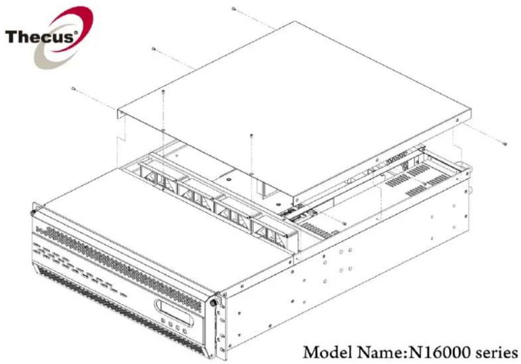
text_image
Thecus® Model Name:N16000 seriesAppendix D: Active Directory Basics
Overview
With Windows 2000, Microsoft introduced Active Directory (ADS), which is a large database/information store. Prior to Active Directory the Windows OS could not store additional information in its domain database. Active Directory also solved the problem of locating resources; which previously relied on Network Neighborhood, and was slow. Managing users and groups were among other issues Active Directory solved.
What is Active Directory?
Active Directory was built as a scalable, extensible directory service that was designed to meet corporate needs. A repository for storing user information, accounts, passwords, printers, computers, network information and other data, Microsoft calls Active Directory a "namespace" where names can be resolved.
ADS Benefits
ADS lets Thecus IP storage integrate itself with the existing ADS in an office environment. This means the Thecus IP storage is able to recognize your office users and passwords on the ADS server. Other major benefits ADS support provides include:
- Easy integration of Thecus IP storage into the existing office IT infrastructure
The Thecus IP storage acts as a member of the ADS. This feature significantly lowers the overhead of the system administrator. For example, corporate security policies and user privileges on an ADS server can be enforced automatically on Thecus IP storage.
- Centralized user/password database
The Thecus IP storage does not maintain its own copy of the user/password database. This avoids data inconsistency between Thecus IP storage and other servers. For example, without ADS support, an administrator might need to remove a specific user privilege on Thecus IP storage and each individual server. With ADS support, the change on an ADS server is known to all of its ADS members.
Appendix E: Licensing Information
Overview
This product included copyrighted third-party software licensed under the terms of GNU General Public License. Please see THE GNU General Public License for extra terms and conditions of this license.
Source Code Availability
Thecus Technology Corp. has exposed the full source code of the GPL licensed software. For more information on how you can obtain our source code, please visit our web site, http://www.thecus.com.
Copyrights
- This product includes cryptographic software written by Eric Young (eay@cryptsoft.com).
- This product includes software developed by Mark Murray.
- This product includes software developed by Eric Young (eay@cryptsoft.com).
- This product includes software developed by the OpenSSL Project for use in the OpenSSL Toolkit (http://www.openssl.org/).
- This product includes PHP, freely available from (http://www.php.net/).
- This product includes software developed by the University of California, Berkeley and its contributors.
- This product includes software developed by Winning Strategies, Inc.
- This product includes software developed by the Apache Group for use in the Apache HTTP server project (http://www.apache.org/).
- This product includes software developed by Softweyr LLC, the University of California, Berkeley, and its contributors.
- This product includes software developed by Bodo Moeller.
- This product includes software developed by Greg Roelofs and contributors for the book, "PNG: The Definitive Guide," published by O'Reilly and Associates.
- This product includes software developed by the NetBSD Foundation, Inc. and its contributors.
- This product includes software developed by Yen Yen Lim and North Dakota State University.
- This product includes software developed by the Computer Systems Engineering Group at Lawrence Berkeley Laboratory.
- This product includes software developed by the Kungliga Tekniska Högskolan and its contributors.
- This product includes software developed by the Nick Simicich.
- This product includes software written by Tim Hudson (tjh@cryptsoft.com).
- This product includes software developed by Christopher G. Demetriou for the NetBSD Project.
CGIC License Terms
Basic License
CGIC, copyright 1996, 1997, 1998, 1999, 2000, 2001, 2002, 2003, 2004 by Thomas Boutell and Boutell.Com, Inc.
Permission is granted to use CGIC in any application, commercial or noncommercial, at no cost. HOWEVER, this copyright paragraph must appear on a "credits" page accessible in the public online and offline documentation of the program. Modified versions of the CGIC library should not be distributed without the attachment of a clear statement regarding the author of the modifications, and this notice may in no case be removed. Modifications may also be submitted to the author for inclusion in the main CGIC distribution.
GNU General Public License
Version 2, June 1991
Copyright © 1989, 1991 Free Software Foundation, Inc. 51 Franklin St, Fifth Floor, Boston, MA 02110-1301 USA
Everyone is permitted to copy and distribute verbatim copies of this license document, but changing it is not allowed.
PREAMBLE
The licenses for most software are designed to take away your freedom to share and change it. By contrast, the GNU General Public License is intended to guarantee your freedom to share and change free software--to make sure the software is free for all its users. This General Public License applies to most of the Free Software
Foundation's software and to any other program whose authors commit to using it. (Some other Free Software Foundation software is covered by the GNU Library General Public License instead.) You can apply it to your programs, too.
When we speak of free software, we are referring to freedom, not price. Our General Public Licenses are designed to make sure that you have the freedom to distribute copies of free software (and charge for this service if you wish), that you receive source code or can get it if you want it, that you can change the software or use pieces of it in new free programs; and that you know you can do these things.
To protect your rights, we need to make restrictions that forbid anyone to deny you these rights or to ask you to surrender the rights. These restrictions translate to certain responsibilities for you if you distribute copies of the software, or if you modify it.
For example, if you distribute copies of such a program, whether gratis or for a fee, you must give the recipients all the rights that you have. You must make sure that they, too, receive or can get the source code. And you must show them these terms so they know their rights.
We protect your rights with two steps: (1) copyright the software, and (2) offer you this license which gives you legal permission to copy, distribute and/or modify the software.
Also, for each author's protection and ours, we want to make certain that everyone understands that there is no warranty for this free software. If the software is
modified by someone else and passed on, we want its recipients to know that what they have is not the original, so that any problems introduced by others will not reflect on the original authors' reputations.
Finally, any free program is threatened constantly by software patents. We wish to avoid the danger that redistributors of a free program will individually obtain patent licenses, in effect making the program proprietary. To prevent this, we have made it clear that any patent must be licensed for everyone's free use or not licensed at all.
The precise terms and conditions for copying, distribution and modification follow.
TERMS AND CONDITIONS FOR COPYING, DISTRIBUTION AND MODIFICATION
- This License applies to any program or other work which contains a notice placed by the copyright holder saying it may be distributed under the terms of this General Public License. The "Program", below, refers to any such program or work, and a "work based on the Program" means either the Program or any derivative work under copyright law: that is to say, a work containing the Program or a portion of it, either verbatim or with modifications and/or translated into another Language. (Hereinafter, translation is included without limitation in the term "modification".) Each licensee is addressed as "you".
Activities other than copying, distribution and modification are not covered by this License; they are outside its scope. The act of running the Program is not restricted, and the output from the Program is covered only if its contents constitute a work based on the Program (independent of having been made by running the Program).
Whether that is true depends on what the Program does.
- You may copy and distribute verbatim copies of the Program's source code as you receive it, in any medium, provided that you conspicuously and appropriately publish on each copy an appropriate copyright notice and disclaimer of warranty; keep intact all the notices that refer to this License and to the absence of any warranty; and give any other recipients of the Program a copy of this License along with the Program.
You may charge a fee for the physical act of transferring a copy, and you may at your option offer warranty protection in exchange for a fee.
- You may modify your copy or copies of the Program or any portion of it, thus forming a work based on the Program, and copy and distribute such modifications or work under the terms of Section 1 above, provided that you also meet all of these conditions:
a) You must cause the modified files to carry prominent notices stating that you changed the files and the date of any change.
b) You must cause any work that you distribute or publish, that in whole or in part contains or is derived from the Program or any part thereof, to be licensed as a whole at no charge to all third parties under the terms of this License.
c) If the modified program normally reads commands interactively when run, you must cause it, when started running for such interactive use in the most ordinary way, to print or display an announcement including an appropriate
copyright notice and a notice that there is no warranty (or else, saying that you provide a warranty) and that users may redistribute the program under these conditions, and telling the user how to view a copy of this License. (Exception: if the Program itself is interactive but does not normally print such an announcement, your work based on the Program is not required to print an announcement.)
These requirements apply to the modified work as a whole. If identifiable sections of that work are not derived from the Program, and can be reasonably considered independent and separate works in themselves, then this License, and its terms, do not apply to those sections when you distribute them as separate works. But when you distribute the same sections as part of a whole which is a work based on the Program, the distribution of the whole must be on the terms of this License, whose permissions for other licensees extend to the entire whole, and thus to each and every part regardless of who wrote it.
Thus, it is not the intent of this section to claim rights or contest your rights to work written entirely by you; rather, the intent is to exercise the right to control the distribution of derivative or collective works based on the Program.
In addition, mere aggregation of another work not based on the Program with the Program (or with a work based on the Program) on a volume of a storage or distribution medium does not bring the other work under the scope of this License.
- You may copy and distribute the Program (or a work based on it, under Section 2) in object code or executable form under the terms of Sections 1 and 2 above provided that you also do one of the following:
a) Accompany it with the complete corresponding machine-readable source code, which must be distributed under the terms of Sections 1 and 2 above on a medium customarily used for software interchange; or,
b) Accompany it with a written offer, valid for at least three years, to give any third party, for a charge no more than your cost of physically performing source distribution, a complete machine-readable copy of the corresponding source code, to be distributed under the terms of Sections 1 and 2 above on a medium customarily used for software interchange; or,
c) Accompany it with the information you received as to the offer to distribute corresponding source code. (This alternative is allowed only for noncommercial distribution and only if you received the program in object code or executable form with such an offer, in accord with Subsection b above.)
The source code for a work means the preferred form of the work for making modifications to it. For an executable work, complete source code means all the source code for all modules it contains, plus any associated interface definition files, plus the scripts used to control compilation and installation of the executable. However, as a special exception, the source code distributed need not include anything that is normally distributed (in either source or binary form) with the major components (compiler, kernel, and so on) of the operating system on which the executable runs, unless that component itself accompanies the executable.
If distribution of executable or object code is made by offering access to copy from a designated place, then offering equivalent access to copy the source code from the same place counts as distribution of the source code, even
though third parties are not compelled to copy the source along with the object code.
- You may not copy, modify, sublicense, or distribute the Program except as expressly provided under this License. Any attempt otherwise to copy, modify, sublicense or distribute the Program is void, and will automatically terminate your rights under this License. However, parties who have received copies, or rights, from you under this License will not have their licenses terminated so long as such parties remain in full compliance.
- You are not required to accept this License, since you have not signed it. However, nothing else grants you permission to modify or distribute the Program or its derivative works. These actions are prohibited by law if you do not accept this License. Therefore, by modifying or distributing the Program (or any work based on the Program), you indicate your acceptance of this License to do so, and all its terms and conditions for copying, distributing or modifying the Program or works based on it.
- Each time you redistribute the Program (or any work based on the Program), the recipient automatically receives a license from the original licensor to copy, distribute or modify the Program subject to these terms and conditions. You may not impose any further restrictions on the recipients' exercise of the rights granted herein. You are not responsible for enforcing compliance by third parties to this License.
- If, as a consequence of a court judgment or allegation of patent infringement or for any other reason (not limited to patent issues), conditions are imposed on you (whether by court order, agreement or otherwise) that contradict the conditions of this License, they do not excuse you from the conditions of this License. If you cannot distribute so as to satisfy simultaneously your obligations under this License and any other pertinent obligations, then as a consequence you may not distribute the Program at all. For example, if a patent license would not permit royalty-free redistribution of the Program by all those who receive copies directly or indirectly through you, then the only way you could satisfy both it and this License would be to refrain entirely from distribution of the Program.
If any portion of this section is held invalid or unenforceable under any particular circumstance, the balance of the section is intended to apply and the section as a whole is intended to apply in other circumstances.
It is not the purpose of this section to induce you to infringe any patents or other property right claims or to contest validity of any such claims; this section has the sole purpose of protecting the integrity of the free software distribution system, which is implemented by public license practices. Many people have made generous contributions to the wide range of software distributed through that system in reliance on consistent application of that system; it is up to the author/donor to decide if he or she is willing to distribute software through any other system and a licensee cannot impose that choice.
This section is intended to make thoroughly clear what is believed to be a consequence of the rest of this License.
- If the distribution and/or use of the Program is restricted in certain countries either by patents or by copyrighted interfaces, the original copyright holder who places the Program under this License may add an explicit geographical distribution limitation excluding those countries, so that distribution is
permitted only in or among countries not thus excluded. In such case, this License incorporates the limitation as if written in the body of this License.
- The Free Software Foundation may publish revised and/or new versions of the General Public License from time to time. Such new versions will be similar in spirit to the present version, but may differ in detail to address new problems or concerns.
Each version is given a distinguishing version number. If the Program specifies a version number of this License which applies to it and "any later version", you have the option of following the terms and conditions either of that version or of any later version published by the Free Software Foundation. If the Program does not specify a version number of this License, you may choose any version ever published by the Free Software Foundation.
- If you wish to incorporate parts of the Program into other free programs whose distribution conditions are different, write to the author to ask for permission. For software which is copyrighted by the Free Software Foundation, write to the Free Software Foundation; we sometimes make exceptions for this. Our decision will be guided by the two goals of preserving the free status of all derivatives of our free software and of promoting the sharing and reuse of software generally.
NO WARRANTY
-
BECAUSE THE PROGRAM IS LICENSED FREE OF CHARGE, THERE IS NO WARRANTY FOR THE PROGRAM, TO THE EXTENT PERMITTED BY APPLICABLE LAW. EXCEPT WHEN OTHERWISE STATED IN WRITING THE COPYRIGHT HOLDERS AND/OR OTHER PARTIES PROVIDE THE PROGRAM "AS IS" WITHOUT WARRANTY OF ANY KIND, EITHER EXPRESSED OR IMPLIED, INCLUDING, BUT NOT LIMITED TO, THE IMPLIED WARRANTIES OF MERCHANTABILITY AND FITNESS FOR A PARTICULAR PURPOSE. THE ENTIRE RISK AS TO THE QUALITY AND PERFORMANCE OF THE PROGRAM IS WITH YOU. SHOULD THE PROGRAM PROVE DEFECTIVE, YOU ASSUME THE COST OF ALL NECESSARY SERVICING, REPAIR OR CORRECTION.
-
IN NO EVENT UNLESS REQUIRED BY APPLICABLE LAW OR AGREED TO IN WRITING WILL ANY COPYRIGHT HOLDER, OR ANY OTHER PARTY WHO MAY MODIFY AND/OR REDISTRIBUTE THE PROGRAM AS PERMITTED ABOVE, BE LIABLE TO YOU FOR DAMAGES, INCLUDING ANY GENERAL, SPECIAL, INCIDENTAL OR CONSEQUENTIAL DAMAGES ARISING OUT OF THE USE OR INABILITY TO USE THE PROGRAM (INCLUDING BUT NOT LIMITED TO LOSS OF DATA OR DATA BEING RENDERED INACCURATE OR LOSSES SUSTAINED BY YOU OR THIRD PARTIES OR A FAILURE OF THE PROGRAM TO OPERATE WITH ANY OTHER PROGRAMS), EVEN IF SUCH HOLDER OR OTHER PARTY HAS BEEN ADVISED OF THE POSSIBILITY OF SUCH DAMAGES.
END OF TERMS AND CONDITIONS