MT10RF - Thermostat Worcester - Free user manual and instructions
Find the device manual for free MT10RF Worcester in PDF.


User questions about MT10RF Worcester
0 question about this device. Answer the ones you know or ask your own.
Ask a new question about this device
Download the instructions for your Thermostat in PDF format for free! Find your manual MT10RF - Worcester and take your electronic device back in hand. On this page are published all the documents necessary for the use of your device. MT10RF by Worcester.
USER MANUAL MT10RF Worcester
INSTALLATION AND OPERATING INSTRUCTIONS
RADIO FREQUENCY CONTROLLED SINGLE CHANNEL MECHANICAL TIMER AND ROOM THERMOSTAT WITH RECEIVER
MT10RF / MECHANICAL
RF THERMOSTAT
7 716 192 037 FOR GREENSTAR i, Si, CDi AND HIGHFLOW CDi COMBINATION BOILERS
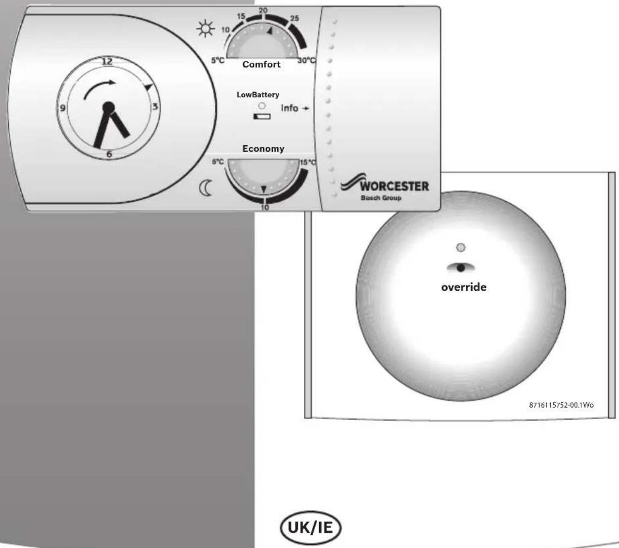
text_image
Comfort LowBattery Info Economy 5°C 10 15 20 25 30°C 5°C 10 15°C WORCESTER Bosch Group override 8716115752-00.1Wo UK/IETABLE OF CONTENTS
1 SYMBOLS AND SAFETY PRECAUTIONS 3
1.1 EXPLANATION OF SYMBOLS 3
WARNING SYMBOLS 3
IMPORTANT INFORMATION....3
ADDITIONAL SYMBOLS 3
2 MANUAL INFORMATION .... 4
GENERAL 4
ABBREVIATIONS 4
3 PRODUCT INFORMATION .... 5
3.1 STANDARD PACKAGE 5
3.2 SPECIFICATIONS 5
3.3 TECHNICAL DATA 6
3.4 RELATED STANDARDS: 6
3.5 EC DIRECTIVES: 6
4 INSTALLATION & COMMISSIONING 7
4.1 FITTING THE RECEIVER .... 7
4.2 PRE-COMMISSIONED TRANSMITTER & RECEIVER LOCATION . 8
4.3 TRANSMITTER RADIO LINK SET UP 10
4.4 TRANSMITTER CLEARANCE & FIXING 11
5 USER INSTRUCTIONS 12
5.1 TRANSMITTER CONTROLS 12
5.2 RECEIVER FUNCTIONS 13
5.2.1 NORMAL OPERATION: 13
5.2.2 SIGNAL RECEIVER: 13
5.2.3 LOW BATTERY STATE: 14
5.2.4 EMERGENCY MODE: 14
5.3 BATTERY REPLACEMENT 14
6 SERVICING & SPARES 16
6.1 TRANSMITTER/RECEIVER MAINTENANCE & SPARES ..... 16
1 SYMBOLS AND SAFETY PRECAUTIONS
1.1 EXPLANATION OF SYMBOLS
WARNING SYMBOLS

Safety instructions in this document are framed and identified by a warning triangle which is printed on a grey background.

Electrical hazards are identified by a lightning symbol surrounded by a warning triangle.
Signal words indicate the seriousness of the hazard in terms of the consequences of not following the safety instructions.
- NOTICE indicates possible damage to property or equipment, but where there is no risk of personal injury.
- CAUTION indicates possible personal injury.
- WARNING indicates possible severe personal injury.
• DANGER indicates possible risk to life.
IMPORTANT INFORMATION

Notes contain important information in cases where there is no risk of personal injury or material losses and are identified by the symbol shown on the left. They are bordered by horizontal lines above and below the text.
ADDITIONAL SYMBOLS
Symbol Meaning
▶a step in an action sequence
→ a reference to a related part in the document or to other related documents
- a list entry
- a list entry (second level)
Tab. 1 Symbols
2 MANUAL INFORMATION
GENERAL
Please read these instructions before starting.
THESE INSTRUCTIONS ARE APPLICABLE TO THE WORCESTER PRODUCT MODELS STATED ON THE FRONT COVER OF THIS MANUAL ONLY AND MUST NOT BE USED WITH ANY OTHER MAKE OR MODEL OF APPLIANCE.
THESE INSTRUCTIONS APPLY IN THE UK ONLY AND SHOULD BE FOLLOWED EXCEPT FOR ANY STATUTORY OBLIGATION.
IF YOU ARE IN ANY DOUBT CONTACT WORCESTER TECHNICAL SUPPORT HELPLINE.
THIS ACCESSORY MUST BE FITTED BY A COMPETENT PERSON. FAILURE TO COMPLY COULD LEAD TO PROSECUTION.
LEAVE THESE INSTRUCTIONS WITH THE USER OR AT THE APPLIANCE.
ABBREVIATIONS
| CH Central Heating | ||||
| DHW Domestic Hot Water | ||||
| RF Radio Frequency | ||||
| LED Light Emitting Diode | ||||
| PCB Printed Circuit Board | ||||
| m | m | e | t | r |
| IP Ingress Protection | ||||
| V Volts | ||||
| mA milli Amps | ||||
| ms milli seconds | ||||
| °C degrees Centigrade | ||||
Tab. 2 Abbreviations
MECHANICAL TIMER SYMBOLS
 | Constant Comfort temperature |
 | Constant Economy temperature |
 | Automatically switches between Comfort and Economy according to the positions of the tappets.Inside edge =ComfortOutside edge = Economy |
Tab. 3 Timer symbols
CONTROLS OVERVIEW
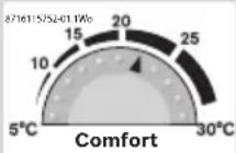 | COMFORT:Higher temperature when dwelling is occupied and heating is required |
 | COMFORT:Move tappets to inside edge of clock for desired period |
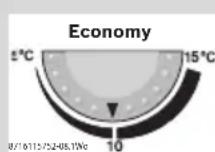 | ECONOMY:Lower temperature when dwelling is unoccupied or at night, when heating is not required, back ground heat will be provided if set point is reached. |
 | ECONOMY:Move tappets to outside edge of clock for desired period. |
Tab. 4 Controls overview
3 PRODUCT INFORMATION
3.1 STANDARD PACKAGE
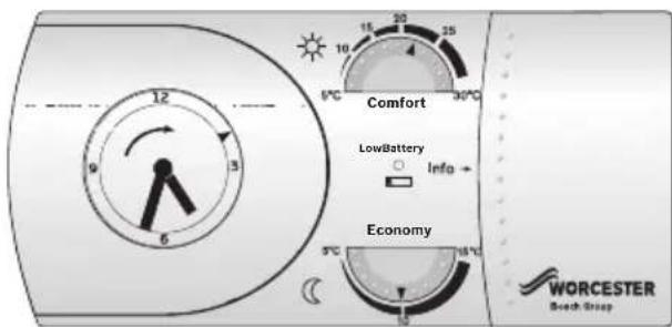
A - Receiver for the Greenstar i, Si, CDi and Highflow CDi combination boilers.
B - Transmitter
C - Screws (x2)
D - Wall Plugs (x2)
E - Instructions
F - Batteries (x2)
text_image
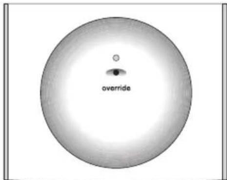
overrideFig. 1 Item A Receiver
text_image
Comfort LowBattery Info → Economy 5°C 10 15 20 25 6°C 30°C 5°C 15°C WORCESTER Beech Stripnatural_image
Technical drawings of three mechanical components: a screw, a stack of papers, and a rolled cylindrical component (no text or symbols)Fig. 3 Items C, D, E & F
3.2 SPECIFICATIONS
TRANSMITTER:
- Single channel, radio frequency central heating timer.
- Mechanical timer with built-in RF transmitter.
- Comfort Temperature dial.
• Economy Temperature dial.
• Built-in battery housing. - Two AA alkaline LR6 batteries.
• LED Battery status indicator.
• Maximum signal range approximately 30 metres (this may vary according to the building's construction).
RECEIVER:
- RF Receiver module with LED receiver status indicator and set up/manual override button.
- Pre-wired with PCB connector.
3.3 TECHNICAL DATA
| Description Units Transmitter Receiver | |||
| Dimensions mm H158 x W75 x D36.5 | |||
| Operating voltage V 2 x AA/LR6 Batteries 24V d.c. | |||
| Ambient Operating Temperature °C -5 to +45 -5 to +45 | |||
| Class of protection – II II | |||
| Degree of protection | IP | 20 | 20 |
| Accuracy | sec/day | ±2.5 @ 25°C | - |
| Battery life | years | 1 approx. | - |
| Shortest switching period | minutes | 15 | - |
| Temperature regulation range | °C | +5 to +30 | - |
| Regulator | - Electronic | - | |
| Transistor switching capacity | mA | - | 5mA @ 24V d.c. |
| Switching contact | -- Open collector | ||
Tab. 5 Technical data
3.4 RELATED STANDARDS:
• BS EN60730-1:2001 + A2:2008
• BS EN60730-2-7:1992
- Electro Magnetic Compatibility (EMC) and Radio Spectrum Matters (ERM); Short Range Devices (SRD) ETSI EN 300 220-1
3.5 EC DIRECTIVES:
• European Union Law Directive (2000/84/EC)
- Low Voltage Directive (2006/95/EC)
- Electro Magnetic Compatibility Directive (2004/108/EC)
• CE Marking Directive (93/68/EEC)
4 INSTALLATION & COMMISSIONING

DANGER:
▶24V & 230V: Do not touch electrical components or circuits.
▶Isolate the mains electricity supply before starting any work and observe all relevant safety precautions.
▶Follow electro static discharge precautions. Do not touch the PCB.
4.1 FITTING THE RECEIVER
▶Switch off the boiler at the electrical supply.
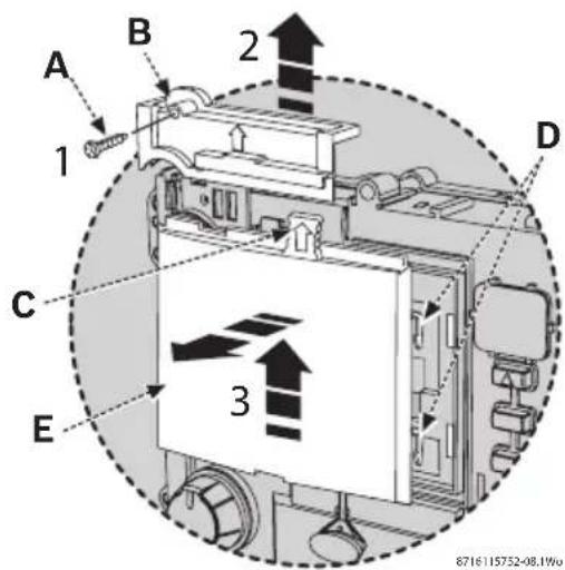
▶Remove boiler outer casing and control panel fascia to gain access to the heatronic control panel.
- Release securing screw [A].
- Pull cover panel [B] upwards to remove.
- Grip tab [C], pull upwards to disengage clips [D] and pull forward to remove blanking plate [E] or existing programmer.
text_image
A 1 B 2 C 3 D E 8716115752-08.19wFig. 4 Removing the blanking plate
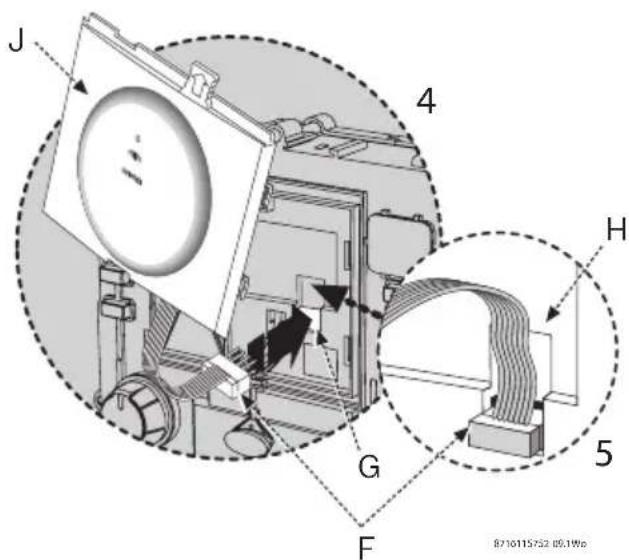
- Align connector pins [F] into receptors [G] in the circuit board and push fully home.
- Feed the ribbon cable [G] into recess [H].
text_image
J 4 H G 5 F B710115752 05.1WcFig. 5 Fitting the receiver
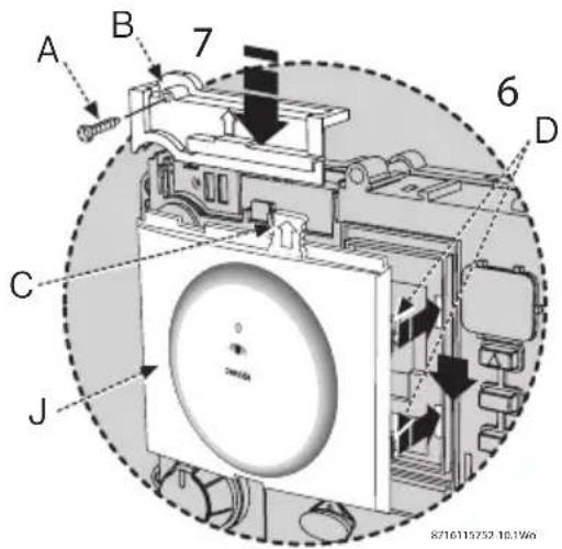
- Align receiver module [J] and locate clips [D], push into slots then downwards to secure using grip tab [C].
- Locate cover panel [B] and secure with screw [A].
- Replace fascia cover and outer casing before switching on the electricity supply.
- Switch the boiler on when completed.
text_image
A B 7 6 D C J 8716115732 10.1W6Fig. 6 Securing the receiver
4.2 PRE-COMMISSIONED TRANSMITTER & RECEIVER LOCATION
The MT10RF Mechanical Thermostat and Receiver are pre commissioned (paired) at the factory.
▶Fit and connect the Receiver in the boiler control panel, see page 7.
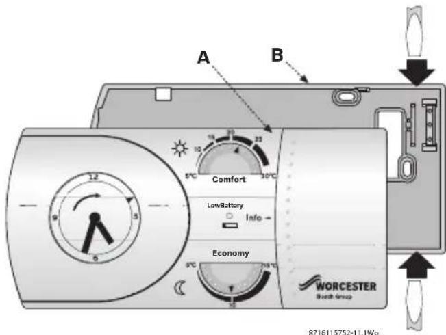
▶Locate a flat bladed screwdriver into the slots in the base plate [B] as shown, twist to release the Transmitter [A] from the base plate [B].
text_image
A B Comfort LowBattery Info Economy WORCESTER Batch Group 8716115752-11.1WsFig. 7 Removing the transmitter
▶Switch on the electrical power to the boiler.
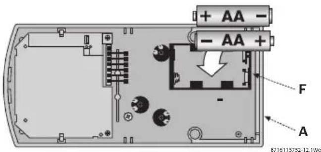
▶Fit the batteries correctly into the battery compartment [F] of the Transmitter [A]. The Transmitter and Receiver will communicate immediately.
The boiler's receiver LED will briefly flash twice when a signal is received.
text_image
+ AA - - AA + F A 8716115752-12.1W0Fig. 8 Fitting the batteries
FUNCTIONAL CHECK
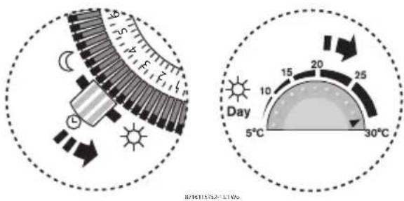
▶Move the manual switch on the Transmitter to the constant comfort position.
▶Rotate the Comfort temperature dial to 30 °C.
▶If the room temperature is less than 30 °C , then within 10 to 30 seconds of making adjustments detailed above, the LED on the receiver will briefly flash twice while detecting the transmitter signal and then remain on. The boiler will fire.
▶If the operation is successful, rotate the comfort dial to your desired room temperature.
▶Move the manual switch on the Transmitter to the Automatic position.
▶Programme the Transmitter to the end user's requirements, see page 12.
If the operation is not successful, follow the Transmitter radio link set up on page 10.
text_image
Day 5°C 10 15 20 25 30°C BC16115/52-1210%Fig. 9 Functional checks
TRANSMITTER LOCATION
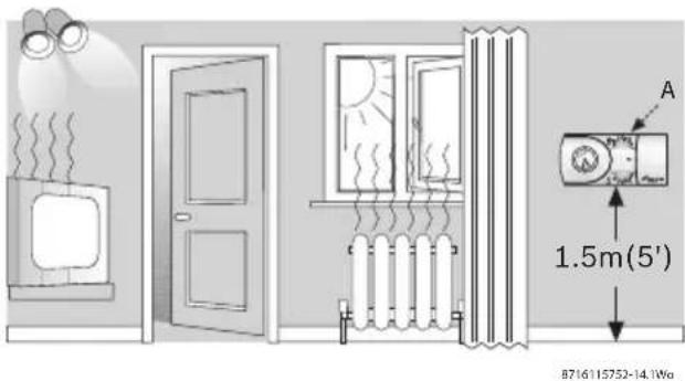
▶Position the Transmitter [A] as close to the main living area as possible on an inside wall. Mount approximately 1.5m (5') above the floor within the maximum range of the boiler's Receiver.
Keep the Transmitter away from:
• light and heat sources
• enclosures and curtains
- direct draughts, including fans, air vents, windows and doors
- damp and condensation
text_image
A 1.5m(5') 8716115752-14.1WwFig. 10 Transmitter location
4.3 TRANSMITTER RADIO LINK SET UP

The procedure will only have to be followed if problems have been experienced with the pre commissioned procedure or if:
▶replacing equipment already installed,
▶recommissioning existing equipment,
REMOVE THE TRANSMITTER FROM THE BASE PLATE
▶Locate a flat bladed screwdriver into the slots in the base plate [B] as shown.
▶Twist to release the Transmitter [A] from the base plate [B]
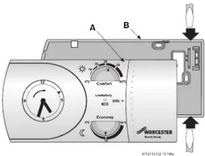
text_image
A B Comfort LowBattery Info + Economy WORCESTER Batch Swap 8710115752-11.1WoFig. 11 Removing the transmitter
ESTABLISH A RADIO LINK
▶Press and hold button [C] down on the Receiver for approximately five seconds to enter the set up mode with the LED [D] on continuously.
The Receiver is now ready to accept a set up signal from the Transmitter for up to two minutes.
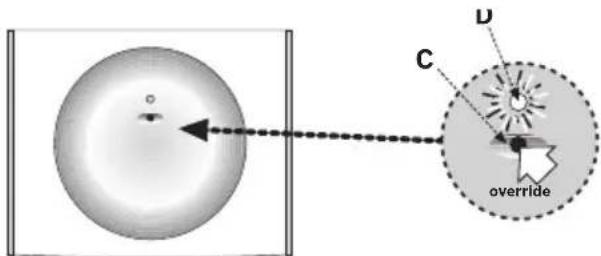
text_image
C D overrideFig. 12 Establish a radio link
▶Fit the batteries correctly into the battery compartment [F].
▶Open the sliding panel to press and release the reset button (see fig 33), to enable the Transmitter to send a set-up signal to the Receiver. Set-up signals are sent for three minutes after pressing and releasing reset.
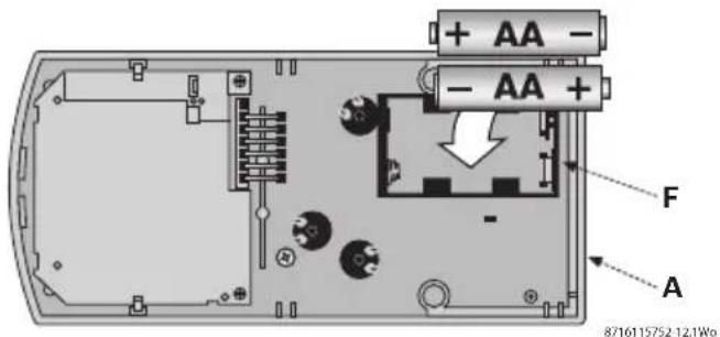
text_image
+ AA - - AA + F A 8716115752 121WoFig. 13 Fitting batteries
When the radio link has been established the LED will briefly flash twice and extinguish. This link remains even in the event of a power loss.
However, if a radio link has not been established, repeat the set-up procedure: as the batteries are already fitted in the Transmitter, simply press and release the reset button to re-initiate continuous transmission of the set-up signal for three minutes.
4.4 TRANSMITTER CLEARANCE & FIXING

NOTICE:
▶All relevant safety precautions must be undertaken. Protective clothing, footwear, gloves and safety goggles must be worn as appropriate.
TRANSMITTER CLEARANCES:
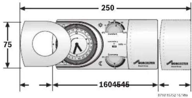
text_image
250 75 1604545 8710115752-16.1WoFig. 14 Transmitter clearances
See diagram above for minimum area (shown in mm) required for operation.
TRANSMITTER FITTING:

CAUTION:
▶Ensure that there are no pipes, electrical cables or other hazards before drilling.
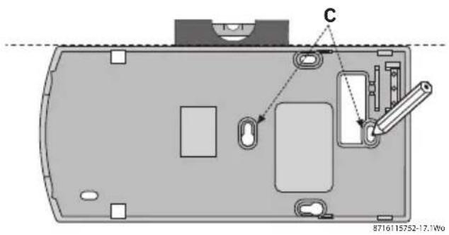
text_image
C 8716115752-17.1WoFig. 15 Transmitter fitting
▶Hold base plate [B] level to mark securing points [C] and remove base plate.
▶Drill holes, where marked, 30mm deep using a 6mm diameter drill bit.
▶Push one wall plug [D] into each hole.
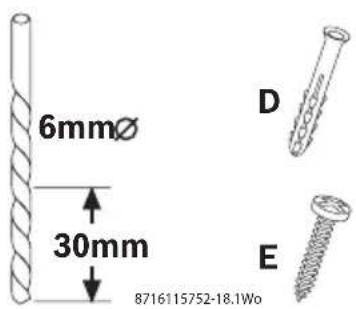
text_image
6mmø 30mm 8716115752-18.1Wb D EFig. 16 Fitting hardware
▶Reposition base plate [B], check level and secure with screws [E].
▶Align outer edge and internal lugs of the Transmitter to base plate [B] and push to secure.
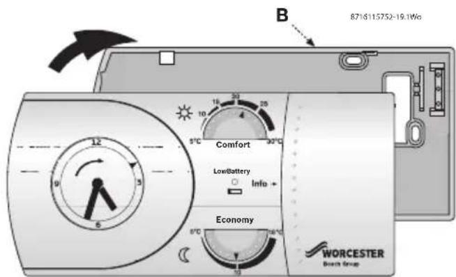
text_image
B 8716115752-19.1Wg Comfort Low/Battery Info + Economy WORCESTER Barch GroupFig. 17 Fitting the transmitter
5 USER INSTRUCTIONS
5.1 TRANSMITTER CONTROLS
INFORMATION:
Slide open panel [A] to reveal details of setting Comfort and Economy [B].
SETTING THE 24 HOUR CLOCK:

The unit may be damaged if you rotate the outer ring anticlockwise.
- Slide cover [D] off the Transmitter [C].
- Rotate outer ring [E] in direction of arrow (clockwise) until the clock hands and the 24 hour pointer [F] display the correct time.
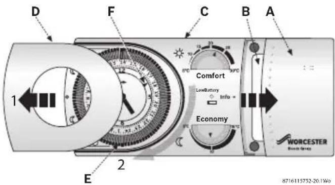
text_image
D F C B A 1 Comfort LowBattery Info Economy 2 E WORCESTER 8716115752-20.1WoFig. 18 Transmitter features
SETTING HEATING TIMES:
-
Using the 1 to 24 hour marks on the outer ring [G] move the tappets [H - each tappet represents 15 minutes]:
-
in for comfort settings
- out for economy setting
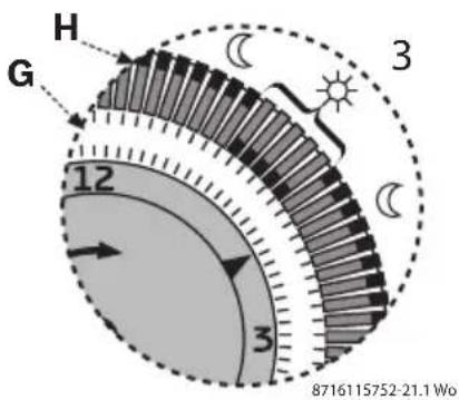
text_image
H G 12 3 3 8716115752-21.1 W0Fig. 19 Setting times
SETTING HEATING TEMPERATURES:
-
Rotate the dials [J] or [K] to set the desired room temperature:
-
5 - 30 °C for Comfort
- 5 - 15 °C for Economy
Typical Comfort and Economy temperature settings are shown below.
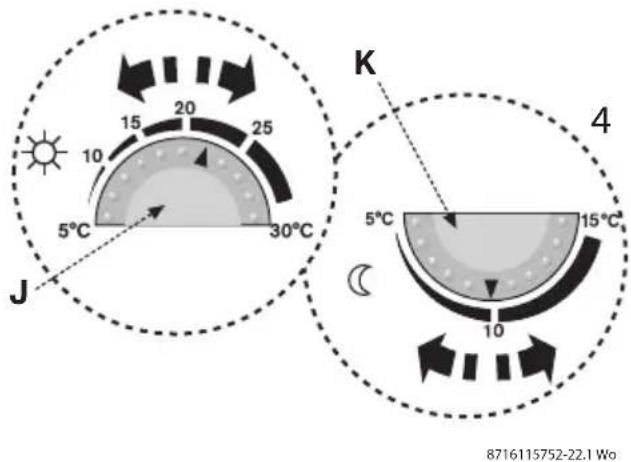
text_image
J 5°C 10 15 20 25 30°C K 4 5°C 10 15°C 8716115752-22.1 WoFig. 20 Setting temperatures
Frost protection is automatically set at 5 °C.
SELECTING PROGRAMS
- Move the selector switch [L] to set:
Automatic, Comfort or Economy.
- Automatic (switches between and uses both Comfort and Economy temperature settings according to the tappets).
- Constant Comfort (continuously on using Comfort temperature setting).
- Constant Economy (continuously on using economy temperature setting).
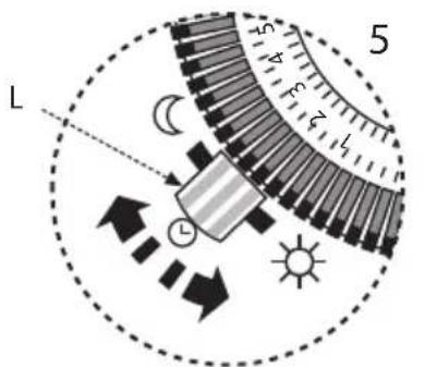
text_image
L 5 4 3 2 1 L S8716115752-23.1 Wo
Fig. 21 Selecting programs
- Replace cover [D] when finished.
5.2 RECEIVER FUNCTIONS
▶LED [A] is continuously on when there is a demand for heating and continuously off when there is no demand for heating.
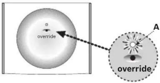
text_image
override A overrideFig. 22 Normal operation
5.2.2 SIGNAL RECEIVER
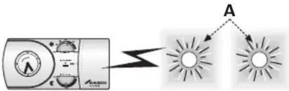
▶LED [A] flashes twice each time a signal is received from the transmitter.
text_image
Diagram showing a device connected to two sun rays labeled A, illustrating light reflection or illumination.Fig. 23 Signal received
5.2.3 LOW BATTERY STATE
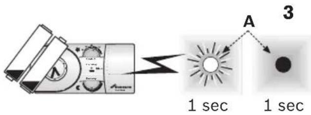
▶LED [A] flashes slowly, on for one second and off for one second.
▶Replace the transmitter batteries as shown under “Battery replacement” section and the receiver will revert back to normal operation.
text_image
1 sec A 3 1 secFig. 24 Low battery state
5.2.4 EMERGENCY MODE
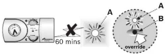
▶If a signal is not received for 60 minutes LED [A] continues to flash rapidly and the central heating is switched off.
▶Press button [B] and release for manual override and to switch the central heating on. Press again to switch the central heating off.
text_image
60 mins A A B overrideFig. 25 Emergency mode
Once a signal is received from the transmitter the receiver and heating will revert back to normal operation.
5.3 BATTERY REPLACEMENT
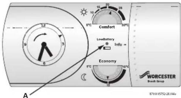
The MT10RF Transmitter includes a battery status indicator [A].

NOTICE:
▶Do not use rechargeable batteries.
text_image
Comfort LowBattery Info + Economy A WORCESTER Brush Group 8716115752-28.1WoFig. 26 Battery status indicator

CAUTION:
▶Do not touch the electrical circuits inside the transmitter
| LED Indicator | Transmitter & mechanical timer operation | Battery condition Replace batteries | |
| OFF Running Full NO | |||
| Flashing yellow Running Low YES | |||
| Flashing red Not running Empty YES | |||
| OFF Not running Empty YES | |||
Tab. 6
TO REPLACE THE BATTERIES:
▶Locate a flat bladed screwdriver into the slots in the transmitter base plate [B].
▶Twist to lift the transmitter [A] away from the base plate [B].

text_image
A B Comfort LowBattery Info + Economy WORCESTER Seat Group 8716115752-11.1WoFig. 27 Removing Transmitter from the base
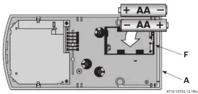
▶Remove existing batteries and dispose of in an environmentally friendly manner.
text_image
+ AA - - AA + F A B716115752-12.1W0Fig. 28 Fitting batteries
▶Replace batteries with the same type and ensure that the batteries are correctly oriented in the battery compartment [F] of the transmitter [A].
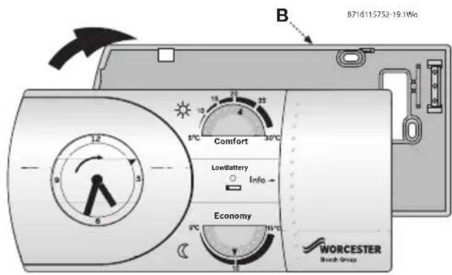
▶Align outer edge and internal lugs of the transmitter to the base plate [B] and push fit to secure.
text_image
B 8716115752-19.1Wg Comfort LowBattery Info Economy WORCESTER Batch GroupFig. 29 Fitting transmitter
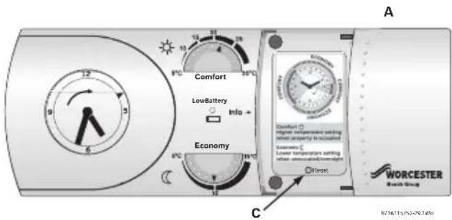
▶Open the sliding panel, press and release the reset button [C] to start normal operation.
text_image
Comfort LowBattery Info + Economy Comfort higher temperature setting when apparently to be installed Economy Lower temperature setting when underneath or overnight Worcel WORCESTER Bench Group A CFig. 30 Reset button
The receiver will revert back to normal operation after the transmitter batteries are successfully replaced.
6 SERVICING & SPARES
6.1 TRANSMITTER/RECEIVER MAINTENANCE & SPARES
TRANSMITTER MAINTENANCE:
text_image
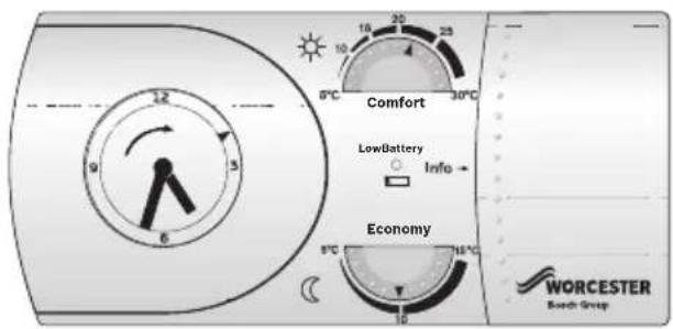
Comfort LowBattery Info → Economy WORCESTER Borch GroupFig. 31 Item A Transmitter
▶Wipe outer casing with a clean dry cloth, do not use polish or detergents.
▶Do not touch any circuits inside the transmitter.
RECEIVER MAINTENANCE:
text_image
overrideB716115752 05.1Wo
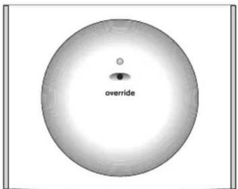
Fig. 32 Item B Receiver
▶The receiver unit [B] requires no maintenance and contains no serviceable components.
SERVICING:
▶These units cannot be serviced.
▶Should the existing unit fail to function correctly, check:
– the receiver times and program settings are correct
- the RF signal link is set up.
- the transmitter batteries are the correct type and fitted correctly.
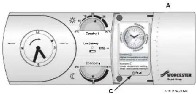
- press reset button [C] on transmitter [A].
text_image
A Comfort LowBattery Info + Economy C WORCESTER Rock Group JX18115752-79.1996Fig. 33 Reset button
REPLACEMENT PARTS:
• Transmitter [A]:
part number 8 716 106 191 0
- Receiver [B] for the Greenstar i, Si, CDi and Highflow CDi combination boilers: part number 8 716 106 664 0
NOTES
NOTES
NOTES
CONTACT INFORMATION
WORCESTER, BOSCH GROUP:
TECHNICAL: 08705 266241
SERVICE: 08457 256206
SERVICE (Eire): 01494 0099
SPARES: 01905 752571
LITERATURE: 01905 752556
TRAINING: 01905 752526
SALES: 01905 752640
WEBSITE: www.worcester-bosch.co.uk