
TDP-T350 - Vidéo-projecteur TOSHIBA - Free user manual and instructions
Find the device manual for free TDP-T350 TOSHIBA in PDF.

| Product Type | Video Projector |
| Brand | Toshiba |
| Model | TDP-T350 |
| Display Technology | 1-chip DMD (Digital Light Processing) |
| Native Resolution | 1024 x 768 (XGA) |
| Lens | Zoom lens F=2.4-2.6, f=23-27.6 mm |
| Projection Screen Size | 33 - 300 inches |
| Projection Distance | 1.29 - 12 m |
| Lamp Type | High-pressure mercury lamp (300 W) |
| Lamp Replacement Model | TLPLW13 (sold separately) |
| Power Consumption | 390 W |
| Weight | 4.9 kg |
| Dimensions (W x H x D) | 340 x 115 x 314 mm |
| Speaker Output | 4 W + 4 W (stereo) |
| Input Terminals | DVI-I (analog/digital RGB & Y/Pb/Pr), COMPUTER2 (Mini D-sub 15 pin), COMPUTER3 (BNC), S-VIDEO, VIDEO, Audio (stereo mini-jack, RCA) |
| Output Terminals | MONITOR OUT (Mini D-sub 15 pin), AUDIO OUT (3.5mm stereo mini-jack) |
| Control Terminal | LAN (10BASE-T/100BASE-TX), RS-232C (Mini DIN 8 pin) |
| Keystone Correction | Auto vertical and manual horizontal/vertical correction |
| Picture Modes | Bright, Standard, True Color |
| Special Functions | PIP, SPLIT, Freeze, Mute, Digital zoom (RESIZE), Auto Setup, Password protection |
| Safety Features | Auto power off, overheat protection, lamp cover interlock |
| What's in the Box | Remote control, batteries (AAA x2), CD-ROM, Owner's Manual, RGB cable, power cord, audio cables, carrying bag, mouse remote control receiver |
Frequently Asked Questions - TDP-T350 TOSHIBA
User questions about TDP-T350 TOSHIBA
0 question about this device. Answer the ones you know or ask your own.
Ask a new question about this device
Download the instructions for your Vidéo-projecteur in PDF format for free! Find your manual TDP-T350 - TOSHIBA and take your electronic device back in hand. On this page are published all the documents necessary for the use of your device. TDP-T350 by TOSHIBA.
USER MANUAL TDP-T350 TOSHIBA
natural_image
Line drawing of a projector with ventilation slots and a circular vent (no text or symbols)SAFETY PRECAUTIONS

The lightning flash with arrowhead symbol, within an equilateral triangle, is intended to alert the user to the presence of uninsulated "dangerous voltage" within the product's enclosure that may be of sufficient magnitude to constitute a risk of electric shock to persons.

The exclamation point within an equilateral triangle is intended to alert the user to the presence of important operating and maintenance (servicing) instructions in the literature accompanying the appliance.
WARNING: TO REDUCE THE RISK OF FIRE OR ELECTRIC SHOCK, DO NOT EXPOSE THIS APPLIANCE TO RAIN OR MOISTURE. DANGEROUS HIGH VOLTAGES ARE PRESENT INSIDE THE ENCLOSURE. DO NOT OPEN THE CABINET. REFER SERVICING TO QUALIFIED PERSONNEL ONLY.
WARNING: Handling the cord on this product or cords associated with accessories sold with this product, will expose you to lead, a chemical known to the State of California to cause birth defects or other reproductive harm. Wash hands after handling
WARNING: This [product] contains mercury. Disposal of mercury may be regulated due to environmental considerations. For disposal or recycling information, please contact your local authorities or the Electronic Industries Alliance: www.eiae.org.
MODEL NAME: TDP-T350
FCC Radio Frequency Interference Statement
Note: This equipment has been tested and found to comply with the limits for a Class USA only A digital device, pursuant to part 15 of the FCC Rules. These limits are designed to provide reasonable protection against harmful interference when the equipment is operated in a commercial environment. This equipment generates, uses, and can radiates radio frequency energy and, if not installed and used in accordance with the instruction manual, may cause harmful interference to radio communications. Operation of this equipment in a residential area is likely to cause harmful interference in which case the user will be required to correct the interference at his own expense.
WARNING: Changes or modifications made to this equipment, not expressly approved by USA only Toshiba, or parties authorized by Toshiba, could void the user's authority to operate the equipment.
WARNING: This is a Class A product. In a domestic environment this product may cause radio interference in which case the user may be required to take adequate measures.
IMPORTANT SAFETY INSTRUCTIONS
CAUTION: PLEASE READ AND OBSERVE ALL WARNINGS AND INSTRUCTIONS GIVEN IN THIS OWNER'S MANUAL AND THOSE MARKED ON THE UNIT. RETAIN THIS BOOKLET FOR FUTURE REFERENCE.
This unit is fully transistorized and does not contain any parts that can be repaired by the user.
DO NOT REMOVE THE CABINET COVER, OR YOU MAY BE EXPOSED TO DANGEROUS VOLTAGE. REFER SERVICING TO QUALIFIED SERVICE PERSONNEL ONLY.
1. Read Owner's Manual
After unpacking this product, read the owner's manual carefully, and follow all the operating and other instructions.

2. Power Sources
This product should be operated only from the type of power source which does not exceed the voltage range specified on the rating label and the power cord. If you are not sure of the type of power supply to your home, consult your product dealer or local power company.

3. Source of Light
Do not look into the lens while the lamp is on. The strong light from the lamp may cause damage to your eyes or sight.

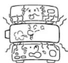
4. Ventilation
Openings in the cabinet are provided for ventilation and to ensure reliable operation of the product and to protect it from overheating, and these openings must not be blocked or covered. The openings should never be blocked by placing the product on a bed, sofa, rug or other similar surface. This product should not be placed in a built-in installation such as a bookcase or rack unless proper ventilation is provided.

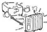
5. Heat
The product should be situated away from heat sources such as radiators, heat registers, stoves, or other products (including amplifiers) that produce heat.
6. Water and Moisture
Do not use this product near water. - for example, near a bath tub, wash bowl, kitchen sink, or laundry tub; in a wet basement; or near a swimming pool and the like.

7. Cleaning
Unplug this product from the wall outlet before cleaning. Do not use liquid cleaners or aerosol cleaners. Use a soft cloth for cleaning.

8. Power-Cord Protection
Power-supply cords should be routed so that they are not likely to be walked on or pinched by items placed upon or against them, paying particular attention to cords at plugs, convenience receptacles, and the point where they exit from the product.

9. Overloading
Do not overload wall outlets; to reduce the risk of electric shock, do not use the polarized plug with an extension cord, receptacle, or other outlet unless the blades can be inserted completely with three-wire grounding type to prevent blade exposure. As this can result in a risk of fire or electric shock.

IMPORTANT SAFETY INSTRUCTIONS (Continued)
10. Lightning storms
For added protection for this product during storm, or when it is left unattended and unused for long periods of time, unplug it from the wall outlet. This will prevent damage to the product due to lightning and power-line surges. However, while it is thundering or lightning, do not touch the apparatus and any connected cable and/or equipment. This will prevent you from receiving the electric shock by an electric surge.
11. Object and Liquid Entry
Never push objects of any kind into this product through openings as they may touch dangerous voltage points or short-out parts that could result in a fire or electric shock. Never spill liquid of any kind on the product.

12. Do not place the product vertically
Do not use the product in the upright position to project the pictures at the ceiling, or any other vertical positions. It may fall down and dangerous.

13. Stack Inhibited
Do not stack other equipment on this product or do not place this product on the other equipment. Top and bottom plates of this product develops heat and may give some undesirable damage to other unit.
14. Attachments
Do not use attachments not recommended by the product manufacturer as they may cause hazards.
15. Accessories
Do not place this product on an unstable cart, stand, tripod, bracket, or table. The product may fall, causing serious injury to a child or adult, and serious damage to the product. A product and cart combination should be moved with care. Quick stops, excessive force, and uneven surfaces may cause the product and cart combination to overturn.

16. Damage Requiring Service
Unplug this product from the wall outlet and refer servicing to qualified service personnel under the following conditions:
a) When the power-supply cord or plug is damaged.
b) If liquid has been spilled, or objects have fallen into the product.
c) If the product has been exposed to rain or water.
d) If the product does not operate normally by following the operating instructions. Adjust only those controls that are covered by the operating instructions as an improper adjustment of other controls may result in damage and will often require extensive work by a qualified technician to restore the product to its normal operation.
e) If the product has been dropped or damaged in any way (If the cabinet should break, please handle with care to avoid injury).
f) When the product exhibits a distinct change in performance - this indicates a need for service.
17. If glass components, including lens and lamp, should break, contact your dealer for repair service.
This product incorporates glass components, including a lens and a lamp. If such parts should break, please handle with care to avoid injury and contact your dealer for repair service. The broken pieces of glass may cause to injury. In the unlikely event of the lamp rupturing, thoroughly clean the area around the projector and discard any edible items placed in that area.
18. Servicing
Do not attempt to service this product yourself as opening or removing covers may expose you to dangerous voltage or other hazards. Refer all servicing to qualified service personnel.

IMPORTANT SAFETY INSTRUCTIONS (Continued)
19. Replacement Parts
When replacement parts are required, be sure the service technician has used replacement parts specified by the manufacturer or have the same characteristics as the original part. Unauthorized substitutions may result in fire, electric shock, or other hazards. (Replacement of the lamp only should be made by users.)
20. Safety Check
Upon completion of any service or repairs to this product, ask the service technician to perform safety checks to determine that the product is in proper operating condition.

21. Do not leave thermal-paper documents or easily deformed items on top of the unit or near the air exhaust for long periods of time.
The heat from the unit could erase the information on the thermal paper, or cause deformation or warping.
- Do not use the product in a closed installation state. Do not place the product in a box or in any other closed installation state. Otherwise it may overheat. This could result in a risk of fire.
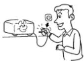
23. Do not look into the laser light source of the remote control or direct the laser pointer toward a person or a mirror.
The laser beam may cause damage to the eyes or sight.
POWER SUPPLY CORD SELECTION
If your line voltage is 220 to 240V, use one of the following types of cable.
| Plug configuration | Plug type | Line voltage |
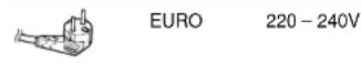
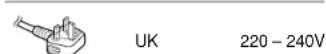
Use a 5A fuse which is approved by ASTA or BSI to BSI362. Always replace the fuse cover after changing the fuse.
| Plug configuration | Plug type Line voltage | |
 | Australian 240V 10A | 200 – 240V |
 | Switzerland 240V 6A | 200 – 240V |
 | North American 240V 15A | 200 – 240V |
IMPORTANT PRECAUTIONS
Save Original Packing Materials
The original shipping carton and packing materials will come in handy if you ever have to ship your projector. For maximum protection, repack the set as it was originally packed at the factory.
Moisture Condensation
Never operate this unit immediately after moving it from a cold location to a warm location. When the unit is exposed to such a change in temperature, moisture may condense on the lens and the crucial internal parts. To prevent the unit from possible damage, do not use the unit for at least 2 hours when there is an extreme or sudden change in temperature.
Place and Manner of Installation
- Do not place in hot locations, such as near heating equipment. Doing so could cause malfunction, and shorten the life of the projector.
- A v oid locations with oil or cigarette smoke. Doing so will dirty the optical parts, shortening their lives, and darkening the screen.
- Do not use this product in the upright position or tilt it up or down by more than 20^ from level. Doing so may cause a failure or shorten the life of the product.
- Using this instrument near a TV or radio may cause interference to the images or audio sound. If this happens, move it away from the TV or radio.
- M o ving the projector from a low-temperature room to a high-temperature room may cause condensation on the lens or internal parts in the instrument. If you continue to use it in that situation, the malfunction may result. Ensure to wait until the condensation naturally disappears.
- In a high altitude location where air is thin, cooling efficiency is reduced so use the projector with [Fan mode] set to [High]. p.44
IMPORTANT PRECAUTIONS (Continued)
Avoid Volatile Liquid
Do not use volatile liquids, such as an insect spray, near the unit. Do not leave rubber or plastic products touching the unit for a long time. They will leave marks on the finish. If cleaning with a chemically saturated cloth, be sure to follow the product's precautions.
EXEMPTION CLAUSES
- Toshiba Corporation bears no responsibility in the case of damages arising from natural disaster such as earthquakes, lightning, etc., fire not liable to Toshiba Corporation, acts by third parties, other accidents, or use under abnormal conditions including erroneous or improper operation and other problems.
- T oshiba Corporation bears no responsibility for incidental damages (lost profit, work interruption, corruption or loss of the memory contents, etc.) arising from the use of or the inability to use this unit.
- T oshiba Corporation accepts no liability whatsoever for any damages arising from not having followed the descriptions in this Instruction Manual.
- Toshiba Corporation accepts no liability whatsoever for any damages arising from malfunctions arising from combination with equipment or software that is not related to Toshiba Corporation.
In the spaces provided below, record the Model and Serial No. located at the bottom of your projector.
Model No. Serial No.
Retain this information for future reference.
OTHER CAUTIONS AND INFORMATIONS
Copyrights
Showing or transmitting commercial imaging software or broadcast or cable-broad casting programs with the purpose of other than the personal and private viewing, including modifying images using the freeze, resize, PIP, or SPLIT screen functions, or displaying with the varying aspect ratio of the images, could violate the direct or indirect copyrights of the imaging software or broadcast program, etc., if done without first consulting with the copyright holder. For this reason, please take appropriate measures before performing one of the actions listed above, including obtaining a license from the copyright holder.
Disposal
This product contains substances which are harmful to humans and the environment.
• The lamp contains mercury.
Please dispose of this product or used lamps in accordance with local regulations.
Trademarks
• V GA, SVGA, XGA, SXGA, UXGA are trademarks or registered trademarks of International Business Machines Corporation.
- Digital Light Processing, Digital Micromirror Device and DMD are trademarks of Texas Instruments.
• Macintosh is a registered trademark of Apple Computer, Inc.
• Windows is a registered trademark of Microsoft Corporation in the U.S. and other countries.
- Adobe is a registered trademark and Acrobat Reader is a trademark of Adobe Systems Incorporated.
Notational Conventions Used in This Manual
- References to pages with related information are annotated as follows. For example, if making a reference to page 36: p.36
- The illustrations in this document are for reference purposes only and may not reflect your package exactly.
REMOTE CONTROL BATTERIES
Caution
- N ever throw batteries into a fire. Using the batteries improperly may cause them to explode or leak and lead to burn or injury. If battery-leaking fluid contacts skin, wash the fluid off immediately with clean water and consult a doctor. If the fluid is split on an instrument, avoid contact and wipe it off using tissue paper. (Dispose of the used tissue paper as flammable garbage after moistening with water.)
Notes
- Be sure to use AAA (LR03) size batteries.
- Dispose of batteries in a designated disposal area.
- Attention should be drawn to the environmental aspects of battery disposal.
- Do not mix different battery types or combine used batteries with new ones.
- If the remote control does not operate correctly, or if the operating range becomes reduced, replace both batteries with new ones.
- If the batteries are dead or if you will not be using the remote control for a long time, remove the batteries to prevent battery acid from leaking into the battery compartment.
CONTENTS
Before Using
SAFETY PRECAUTIONS 2
IMPORTANT SAFETY INSTRUCTIONS 4
POWER SUPPLY CORD SELECTION 9
IMPORTANT PRECAUTIONS 9
EXEMPTION CLAUSES 10
OTHER CAUTIONS AND INFORMATIONS 11
REMOTE CONTROL BATTERIES 11
CONTENTS 12
Preparations
Checking the package contents 14
Names of each part on the main unit 15
Names of each part on the control panel and remote control 16
Label locations 17
Parts on the rear panel 18
Preparing and using the remote control 20
Operating a computer using the remote control 21
Placement 22
Connection 24
Operations
Turning the power on and off 26
Basic operations 28
Using handy features 30
Using auto setting 30
Correcting the keystone distortion 30
Resizing image 31
Cutting off the picture and sound temporarily (Mute) 32
Changing picture mode 33
Changing screen size 33
Freezing the image (Freeze) 33
Display a sub screen (PIP function) 34
Sub screen setting 34
Displaying two screens (SPLIT function) 35
SPLIT function setting 35
Screen combination of PIP and SPLIT functions 36
Password function 36
Using the menus 38
How to use the menus 38
The image adjustment menu 39
The display setting menu.... 41
The default setting menu 44
The control setting menu 46
Displaying Information (Status display) 48
Maintenance
About lamp 49
Lamp replacement 49
Lens and main unit cleaning 52
Others
Trouble indications 53
Before calling service personnel 54
Specifications.... 55
List of general specifications 55
Separately sold product.... 55
List of supported signals (RGB signals) 56
List of supported signals (Y/P B/PR signals) 57
List of supported signals (Video, S-Video signals) 57
Pin assignment of COMPUTER-2 & MONITOR terminals 57
Pin assignment of DVI-I terminal 58
CONTROL terminal 59
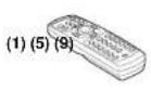
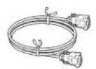
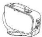
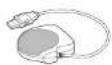
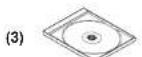
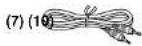
Checking the package contents
Please make sure that the following items are included in the box, along with the main unit. If any item is missing, please contact the store immediately where you purchased the product.
(2)
(6)
(4) (8)

□ (1) Remote control
☐ (2) LR03 (SIZE AAA) batteries for remote control (2)
□(3) CD-ROM
□ (4) Owner's Manual
□(5) RGB cable (3m)
☐ (6) Power cord (see note)
☐ (7) Audio cable (for computer input)
☐ (8) Audio cable (for video input)
□ (9) Carrying bag
□1) Mouse remote control receiver
Note
The shape and number of supplied power cords vary depending on the product destination.
◆The Supplied CD-ROM
The supplied CD-ROM contains an owner's manual, including information not available for the printed Owner's manual (Getting started) and Acrobat® Reader™ to view the manual.
■ Installing Acrobat® Reader™
Windows ^® : Run the CD-ROM, select the Reader/English folder, and run ar500enu.exe. Follow the on-screen instructions. Macintosh: Run the CD-ROM, select the Reader/English folder, and run Reader Installer. Follow the on-screen instructions to install the software.
■ Viewing the manual
Run the CD-ROM and double-click on Start.pdf. Acrobat * Reader™ launches, and the menu screen of the Owner's manual appears. Click on your language. The Owner's Manual cover and list of bookmarks appear. Click on a bookmark title to view that section of the manual. Click on p. to view a reference page with related information. See the Help menu for more information about Acrobat® Reader™.
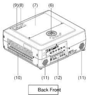
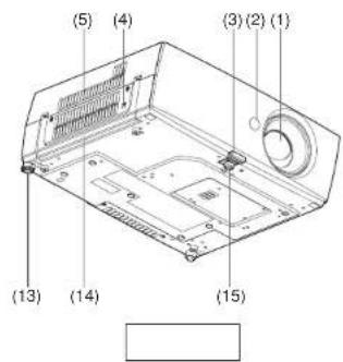
Names of each part on the main unit
Name
: Function
(1) Lens
(2) Infrared remote sensor
(3) Foot adjuster release button
(4) Antitheft lock hole
(5) Air exhaust
(6) Control panel
(7) Lamp cover
(8) Zooming lever
(9) Focusing lever
(10) Air intake
(11) Speaker
(12) Rear panel
(13) Tilt adjuster
(14) Handle
(15) Foot adjuster
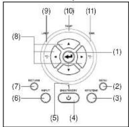
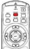
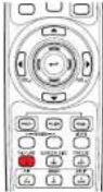
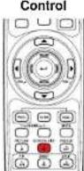
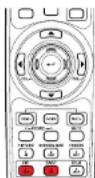
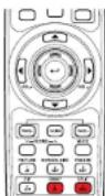
Names of each part on the control panel and remote control
Control panel Remote Control
CAUTION
- Do not look into the laser light source of the remote control or direct the laser pointer toward a person or a mirror.
- Handling and adjusting other than described here may lead to dangerous exposure to laser.
Name : Main Function
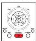
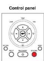
Control panel
(1) ENTER button : Accepts the selected mode.
(2) MENU button : Displays menus.
(3) KEYSTONE button: Adjusts keystone distortion.
(4) ON/STANDBY button: Turns the power on/off (standby).
(5) ON/STANDBY indicator : Displays whether power is on or off.
(6) INPUT button : Selects input. p.28
(7) RETURN button : Goes back one screen.
(8) Selection button : Menu selections and adjustments, volume control, etc.
p.38
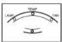
(9) LAMP indicator : Displays lamp mode. p.27
(10) TEMP indicator : Lights when internal temperature is too high. p.53
(11) FAN indicator : Displays cooling fan mode.
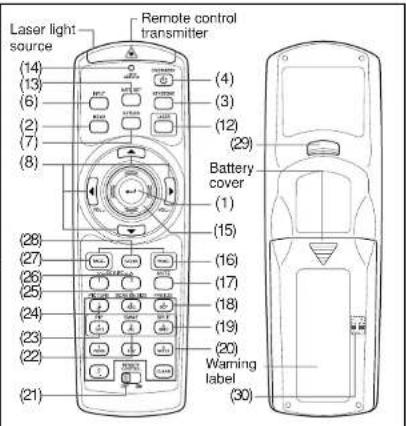
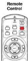
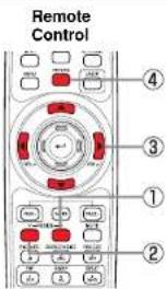
Remote control
(1) ENTER button : Accepts the selected mode.
(2) MENU button : Displays menus.
(3) KEYSTONE button: Adjusts keystone distortion.
(4) ON/STANDBY button: Turns the power on/off (standby).
(6) INPUT button: Selects input.
(7) RETURN button : Goes back one screen.
(8) Selection button : Menu selections and adjustments, volume control, etc.
p.38
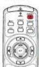
(12) LASER button : Shows a laser pointer.
Name: Main Function
| (13) AUTO SET button | : Sets up analog input from computer. p.30 |
| (14) Laser indicator | : Lights when laser is on. |
| (15) Mouse control button | : Controls a mouse pointer. p.21 |
| (16) PAGE+ button | : Proceeds PowerPoint® slides. p.21 |
| (17) MUTE button | : Cuts off the picture and sound temporarily. p.32 |
| (18) FREEZE button | : Pauses image. p.33 |
| (19) SPLIT button | : Displays two screens. p.35 |
| (20) Ten-Key button | : Use as a ten-key pad with wired LAN, from which numbers and characters can be entered. p.47 |
| (21) Remote control ON/OFF switch | : Switches on/off the remote control. p.20 |
| (22) SWAP button | : Swaps the main screen and the sub screen in PIP mode, or swaps the two screens in SPLIT mode. p.34 |
| (23) PIP button | : Displays the sub screen. p.34 |
| (24) PICTURE button | : Changes image mode. p.33 |
| (25) SCREEN SIZE button | : Changes screen size. p.33 |
| (26) RESIZE button | : Enlarges image. p.31 |
| (27) PAGE- button | : Goes back PowerPoint® slides. p.21 |
| (28) R-CLICK button | : Functions as right-click of a mouse. p.21 |
| (29) L-CLICK button | : Functions as left-click of a mouse. p.21 |
| (30) Remote control code switch (inside the battery cover) | : Sets the code of remote control to that of the projector. p.45 |
Note
- For the remainder of this manual, buttons are referred to as follows:
Selection buttons ⇒ △ ▼ ◀ ▶; ENTER button ⇒ 📞
Label locations
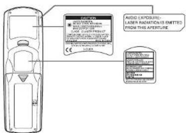
Caution – use of controls or adjustments or performance of procedures other than those specified herein may result in hazardous radiation exposure.
Parts on the rear panel
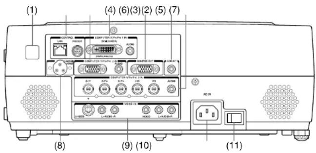
Name : Main Function
(3) COMPUTER (Y/PB/PR) 2 IN terminal
RGB : Input analog RGB signal from a computer or other source, or a component video signal (Y/PB/PR) from video equipment.
AUDIO : Input audio signals.
(4) COMPUTER (Y/P b/Pr) 1 IN terminal
DVI-I : Input analog or digital RGB signal from a computer, or a component video signal (Y/Pb/Pr) from video equipment.
AUDIO : Input audio signals.
(5) MONITOR terminal : Connect to a computer display, etc.
(6) AUDIO OUT terminal : Outputs audio signals.
(7) COMPUTER (Y/P b/Pr) 3 IN terminal
BNC : Input G/B/R/HD/VD signal from a computer, or a component video signal (Y/Pb/Pr) from video equipment.
AUDIO : Input audio signals.
(8) CAMERA POWER terminal : DC power supply terminal (+15 V). Reserved for future use.
(1) Infrared remote sensor
(2) CONTROL terminal
: Senses commands from the remote control. p.20
LAN : Connects a network cable.
RS232C : When operating the projector via a computer, connect this to the controlling computer's RS-232C port. p.59
Name : Main Function
(9) VIDEO IN terminal
S-VIDEO : Input S video signals from video equipment.
AUDIO (L/R) : Input audio signals from video equipment.
VIDEO: Input video signals from video equipment.
AUDIO (L/R) : Input audio signals from video equipment.
(10) A C IN socket : Connect the supplied power cord here.
(11) Main power switch : AC power line ON (standby)/OFF.
Preparing and using the remote control
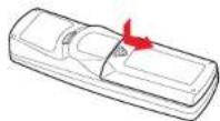
■ Loading dry-cell batteries into the remote control
① Remove the battery cover.
② Insert the dry-cell batteries.
Be sure to align the plus and minus ends of the batteries properly.
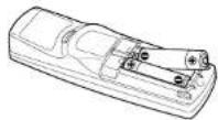
Two batteries (LR03, SIZE AAA) are used.
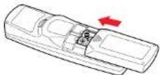
③ Replace the battery cover.
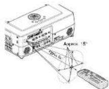
■ Operating the remote control
Turn on the ON/OFF switch of the remote control. Point toward the projector's infrared remote sensor, and press a button on the remote control.
- Operating the projector from the front
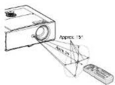
- Operating the projector from the rear
Dry-cell batteries
- Before using the batteries, be sure to observe the Safety Precautions described in previous pages.
- Remove batteries from remote control when not using for extended periods.
- If the remote control stops working, or if its range decreases, replace all the batteries with new ones.
The remote control
- Turn off the ON/OFF switch of the remote control when not in use or to store in baggage.
- The remote control may fail to operate if the infrared remote sensor is exposed to bright sunlight or fluorescent lighting.
- Do not drop or bang.
- Do not leave in hot or humid locations.
- Do not get wet or place on top of wet objects.
- Do not take apart.
- In rare cases, ambient conditions could impede the operation of the remote control. If this happens, point the remote control at the main unit again, and repeat the operation.
Operating a computer using the remote control
A computer can be operated using the projector's remote control. This function is available on any computer with the Windows 98/98SE, Windows Me, Windows 2000, or Windows XP OS, that is equipped with a USB port which can support USB1.1 (The mouse remote control receiver is also supported on OS 9 or OS X for the Macintosh). However, please note that Toshiba does not guarantee the operation of all computers.
① Connecting a computer
Connect the mouse remote control receiver (supplied) to a computer.
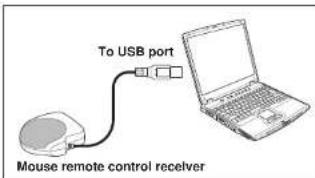
The remote control may fail to operate if the mouse remote control receiver is exposed to bright sunlight or fluorescent lighting.
In such a case, change position or direction of the mouse remote control receiver and retry.
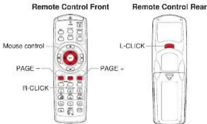
② Operating a computer
Operate remote control's buttons towards the mouse remote control receiver.
● Moving the mouse pointer
Press the mouse control button in the direction you wish the mouse pointer to move, then press.
Press the mouse control button in the direction you wish the mouse pointer to move, then press.
● To left click
Press the L-CLICK button.
● To right click
Press the R-CLICK button.
● To drag and drop
Holding down the L-CLICK button, move the mouse control button until the mouse pointer is over the desired location, then release the L-CLICK button.
- Using the computer's page up [↑] and down [↓] function
Press the PAGE+ and PAGE- buttons to switch PowerPoint slides.
Placement
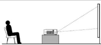
Placement Styles
As shown in the figures below, this device can be placed in 4 different styles.
The factory setting is "floor-mounted front projection." Set the [Projection mode] in the Default setting menu p.44, in accordance with your needs.
Floor-mounted front projection
natural_image
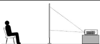
Silhouette of a person sitting at a desk facing a laptop and projecting a screen (no text or symbols visible)Floor-mounted rear projection
natural_image
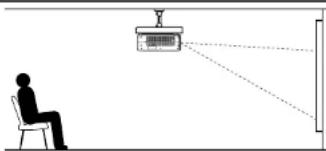
Silhouette of a person sitting on a chair facing a vertical pole with a screen, connected by a dotted line (no text or symbols)Ceiling-mounted front projection
natural_image
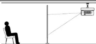
Silhouette of a person sitting on a chair facing a projection screen, with dashed lines indicating perspective (no text or symbols)Ceiling-mounted rear projection
natural_image
Silhouette of a person sitting on a chair facing a vertical pole with a monitor and antenna, connected by dashed lines (no text or symbols)WARNING
- Always obey the instructions listed in IMPORTANT SAFETY INSTRUCTIONS when placing the unit. Attempting to clean/replace the lamp at a high site by yourself may cause you to drop down, thus resulting in injury.
- If you wish to mount the projector on the ceiling, be sure to ask your dealer to do so. Mounting the projector on a ceiling requires special ceiling brackets (sold separately) and specialized knowledge. Improper mounting could cause the projector to fall, resulting in an accident.
- If the projector is ceiling-mounted, install the breaker for turning off the power in case of anomaly. Let everyone involved with the use of the projector know that fact.
Projection Distance and Size
Use the figures, tables, and formulas below to determine the projection size and projection distance. (Projection sizes are approximate values for full-size picture with no keystone adjustment.)
Screen As seen from above
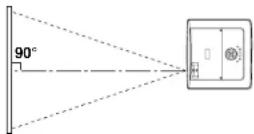
a (min length) = size (inches) - 1.459629.888
a (max length) = size (inches) - 1.208424.744
| projection size (inches) | projection distance a (m) | height [H](cm) | |
| min length (zooming max) | max length (zooming min) | ||
| 33 | - | 1.29 | 6.8 |
| 40 | 1.29 | 1.57 | 8.2 |
| 60 | 1.96 | 2.38 | 12.3 |
| 80 | 2.63 | 3.18 | 16.5 |
| 100 | 3.30 | 3.99 | 20.6 |
| 150 | 4.97 | 6.01 | 30.9 |
| 200 | 6.64 | 8.03 | 41.1 |
| 250 | 8.32 | 10.05 | 51.4 |
| 300 | 9.99 | 12.08 | 61.7 |
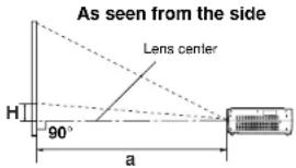
a is the distance (m) between the lens and the screen, and corresponds to a range of 1.29 m to 12.10 m. H is the height from the image bottom to the center of the lens.
Connection
Before connection
- Read the owner's manual of the device you are connecting to the projector.
- Some types of computer cannot be used or connected to this projector.
Check for an RGB output terminal, supported signal p.56, etc.
• T urn off the power of both devices before connecting.
• The figures are sample connections.
Connecting with computers
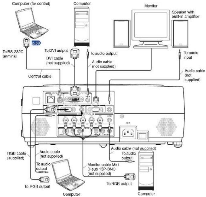
Notes
- Signals are output from MONITOR OUT terminal even in standby mode.
From AUDIO OUT terminal, no audio signal is output. -
M o ving pictures played back on computers using DVD software may appear unnatural if it is projected with this projector, but it is not a malfunction.
-
The MONITOR OUT terminal outputs analog RGB signals or component video signals (Y/Pb/Pr) from the COMPUTER 1 IN, COMPUTER 2 IN, or from the COMPUTER 3 IN terminal as selected with the INPUT button. If no input is selected, the MONITOR OUT terminal outputs the input signals last selected among the COMPUTER 1 IN, COMPUTER 2 IN, and the COMPUTER 3 IN terminals. (Digital RGB signals are not output.)
• A computer monitor usually cannot accept Y/PB/PR signals correctly.
Connecting with AV equipment
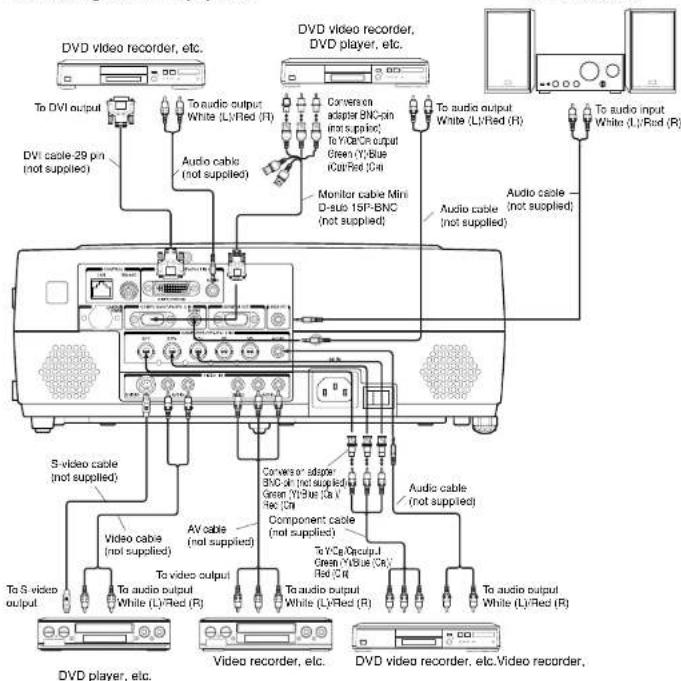
Notes
- When an AUDIO OUT terminal is connected, sound is not output from the projector speaker.
- Output volume of AUDIO OUT terminal can be adjusted by the VOL button.
Turning the power on and off
■ Connecting the power cord
① Insert the power cord connector into the AC IN socket of the projector.
② Insert the power cord plug into a wall or other power outlet.
■ Removing the lens cover
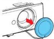
Be sure to remove the lens cover when the power is turned on. If it is left on, it could become deformed due to heat.
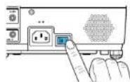
■ Turning the power on
① Turn on the main power switch.
The ON/STANDBY indicator will change to orange, indicating standby mode.
② Press the ON/STANDBY button.
The power turns on with a beep sound (if the beep sound is set to [On]), and the following 3 green indicators light: ON/STANDBY, LAMP, and FAN. After a moment, the start-up screen appears.
Control panel
Remote Control
Start-up screen

CAUTION
- Do not look into the lens while the lamp is on. The strong light from the lamp may cause damage to your eyes or sight.
- Do not block the air intake or exhaust. Doing so could cause a fire due to internal overheating.
- Do not place your hands, face, or other objects near the air exhaust. Doing so could cause burns, deform/break the object.
Notes
- The start-up screen will disappear after a moment. You can dismiss the start-up screen before this by performing any operation. You can also configure the start-up screen not to appear via the Display setting menu p.41.
- The first time you use the projector after purchase, after the start-up screen disappears, the start menu is displayed p.28.
- You can disable the beep sound in the Display setting menu p.41
- When [Key lock] is [On], the operation buttons of the projector do not work p.44
- When [Password] is [On], the start-up screen is displayed after the Password entry screen disappears p.44.
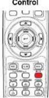
■ Turning the power off
① Press the ON/STANDBY button.
A message appears on the screen, confirming that you wish to shut off the power. This message will disappear after a moment. (This operation is no longer valid after the message disappears.)
② Press the ON/STANDBY button again.
A beep sound is made (if the beep sound is set to [On]) and the screen turns off, but the internal cooling fan continues to operate for a short while. Then, the projector goes into standby mode.
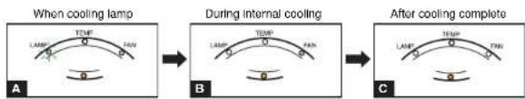
flowchart
graph LR
    A["When cooling lamp"] --> B["During internal cooling"]
    B --> C["After cooling complete"]
A During cooling, the LAMP indicator flashes. In this state, the power cannot be turned back on.
If you are in a hurry, there is no problem with unplugging the power cord or turning off the main power switch in this state.
B After the LAMP indicator goes off, the FAN indicator keeps lighted and the cooling fan continues to operate for a short while, in order to expel excess internal heat.
C In standby mode
Note
- The projector consumes about 16W of power in standby. We recommend that you unplug the power cord or turn off the main power switch if you will not be using the projector for an extended period.
PRECAUTION
- If the power cord is unplugged before cooling is complete, give the lamp time (about 5 minutes) to cool before plugging it back in. If the lamp overheats, it may fail to light.
Basic operations
① Turn on the power.
Turn on the power by following the instructions in "Turning the power on" p.26.
② Select the language and the lamp power (When using the first time).
When the projector is used for the first time after purchase, the start menu for language (to display the menus and messages on the screen) and lamp power selection and configuration is displayed in English. (If the screen is out of focus, adjust it according to the step 6.)
① Use the 🔒 or ⏻ button to select the desired language and press the 🔑 button. Message for setup confirmation is displayed in a selected language.
Then, the menu for lamp power selection and configuration is displayed. It is automatically set as Standard. To change the setting, follow the step ②.
② Use the 📋 button to select the lamp power and press the ⏻ button.
The lamp power, if selected, will be toggled without pressing the ⏻ button. The display automatically disappears in a few seconds.
| English...... | English |
| Français...... | French |
| Deutsch...... | German |
| Italiano...... | Italian |
| Español...... | Spanish |
| Portugues...... | Portuguese |
| Русский...... | Russian |
| Svenska...... | Swedish |
| Türkçe...... | Turkish |
| Polski...... | Polish |
| 日本語...... | Japanese |
| 中文(简体字)...... | Chinese (simplified) |
| 中文(繁體字)...... | Chinese (traditional) |
| 한국어...... | Korean |
Notes
- When the projector is turned on the next time, the start menu does not appear upon startup. However, if [Reset all] is executed from the Default setting menu p.44, the start menu will be displayed the next time when the power is turned on.
- The language can also be set via the Display setting menu p.41 and Lamp power via the Default setting menu p.44.
- This owner's manual assumes that English has been selected.
③ Activate the connected device.
Turn on and start the connected device such as a computer.
4 Press the INPUT button.
An image of the connected equipment is projected. Each time you press the INPUT button, it switches to the input of the connected equipment that is outputting video signals.
Notes
- When [Auto Input search] is set to [On] in the Default setting menu p.44 (factory setting is [On]), the input is switched to the connected equipment that is outputting video signals each time you press the INPUT button p.45.
- If no signal is being output from the connected equipment, pressing the INPUT button does not change the input and "There is no other input signal." will appear.
⑤ Projector placement angle adjustments
The placement angle and the height of the projected image can be adjusted by the foot adjuster.
① Lift up the front of the projector to the desired angle, then press the foot adjuster release button.
The foot adjuster extends. Release the button to lock the position.
② To fine adjust the angle, twist the foot adjuster.
③ To adjust the horizontal angle, use the tilt adjuster.
To stow the foot adjuster, hold up the projector while pressing the foot adjuster release button, then slowly lower the projector.
⑥ Adjusting the screen size and focus
① Use the zooming lever to adjust the screen size.
② Use the focusing lever to adjust the focus.
Adjusting the volume with the ◀▶ buttons
The speaker volume can be adjusted when an audio signal is being input.
Notes
- Note that lamp characteristics may rarely cause the brightness to fluctuate slightly.
- A lamp is consumable item. If used for extended periods, images will appear dark, and the lamp could burn out. This is characteristic of a lamp, and is not malfunction. (The lifetime of the lamp depends on conditions of use.)
- The DMD ^TM is made using extremely advanced technology, but there may be black spots (pixels that do not light) or bright spots (pixels that are constantly lit) on the panel. Please note that these are not malfunctions.
- Although this projector supports a wide range of RGB signals p.56, any resolutions not supported by this projector (XGA) will be expanded or shrunk, which will affect image quality slightly. To view high-quality images, it is recommended that the computer's external output should be set to XGA resolution.
- With some models of computer having LCD displays or the like, displaying images simultaneously on the projector and the monitor's display may prevent the images from displaying properly. If this happens, turn off the computer's LCD display. For information on how to turn off the LCD display, see the owner's manual of your computer.
- If no signal is being input from the connected equipment or signal input is stopped while projecting, the "No signal" will appear.
- If a signal not supported by the projector is input, the "Unsupport signal" will appear.
- If an unavailable operation button is pressed, the ✗ icon will appear.
Using handy features
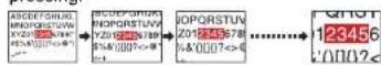
■ Using auto setting (Only for analog Input from computer)
This function sets up the projector to the optimum state such as sampling phase, frequency, screen position, and clamp for each type of the input signal by using simple operations.
- Press the remote control's AUTO SET button.
For computer input, the icon will appear during processing. You can set as well by selecting [Auto setting] in the Image adjustment menu p.39.
Remote Control
Notes
- The image may not be projected or auto adjustment/setting may not be performed correctly for input signals other than those supported by the projector p.56, p.57.
- If auto setting fails adjustment, adjust manually with the Image adjustment menu p.39.
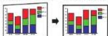
■ Correcting the keystone distortion
When the projector placement angle against the screen is changed while projecting the image, the picture will undergo keystone (trapezoidal) distortion.
This projector is capable of correcting this keystone distortion.
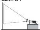
⑦ Press the KEYSTONE button.
The Keystone menu appears. By default, [Auto v-keystone] is selected.
| Item Description | |
| Auto v-keystone | Automatically corrects the vertical distortion. Press 📐 . |
| V-keystone | Screen shrinking at S### shrinking at bottom top |
| H-keystone | Screen shrinking on S### shrinking on the left the right |
Adjusting vertical distortion [Auto]
② Press the button.
The keystone distortion is automatically corrected. The ☐ on appears during this correction. When adjustment is finished, the Keystone menu appears again. For fine adjustment, select [V-keystone] by the ▼ button and adjust image manually by the ▼ buttons.
Adjusting vertical distortion [Manual]
① Press the KEYSTONE button.
② Select [V-keystone] by the ▼ button.
③ Use the ▶▶ buttons for keystone adjustment.
Adjusting horizontal distortion [Manual]
① Press the KEYSTONE button.
② Select [H-keystone] by the ▼ button.
③ Use the ◀▶ buttons for keystone adjustment.
When the adjustment is finished, the menu automatically disappears. The menu also disappears when the KEYSTONE or RETURN button is pressed.
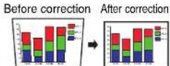
Before correction After correction
Notes
- To adjust both vertical and horizontal keystones, adjust vertical keystone at first. - Depending on the amount of keystone adjustment and the content of images, some information may be lost, or the picture quality may suffer.
■ Resizing image
The projected image can be resized (zoomed in/out).
f Press the remote control's RESIZE ↗ button.
Each time you press the RESIZE ▲ button, zoom ratio is up. You can keep pressing.
Using handy features (Continued)
② Tozoom out, press the remote control's RESIZE button.
Each time you press the RESIZE button, zoom ratio is down. You can keep pressing.
(However, the image cannot be smaller than the original size.)

To move the area to zoom in, use the ▼ ▲ ▶ △ buttons.
You can keep pressing.

④ To reset the zoom, press the RETURN button.
The image is reset to the original size.
Notes
• The icon appears while resizing.
- Operating a function other than Mute will release resizing.
- As zooming is processed digitally, the image quality is degraded in larger zoom ratio.
- During resizing or moving the zooming area, the image may be distorted.
■ Cutting off the picture and sound temporarily (Mute)
When you want to project the images of another projector, overhead projector, etc. temporarily, this projector's images and sound can be turned off.
Press the remote control's MUTE button.
The picture and sound are cut off. (The Mute function is released when pressing the MUTE button again.)
Notes
• The ☐ on will appear while mute is in effect.
- Operating any other functions will also cancel the muting.
Remote
■ Changing picture mode
The projected image mode can be selected.
- Press the remote control's PICTURE button.
Pressing the button switches Bright/Standard/True color in turn.
Note
• [Picture mode] of the Image adjustment menu has the same function p.39.
■ Changing screen size
The screen size for the projected image can be changed.
Press the remote control's SCREEN SIZE button. Pressing the button switches Full/Thru/Wide in turn.
Notes
- Thru display is available for computer-input images.
- [Screen size] of the Display setting menu has the same function p.41.
- If you use this function on commercial video software, broadcast or cable-broadcasting except for the purpose of your private viewing and listening, it may infringe the copyright protected by the copyright laws.
■ Freezing the image (Freeze)
The image being projected can be frozen. This function is to be used to pause a video during a presentation, etc.
- Press the remote control's FREEZE button.
The picture pauses. (The Freeze function is released when pressing the FREEZE button again.)
Notes
• The icon will appear while freeze is in effect.
- Other operation will also release the freeze.
- E v en if an image is frozen on the projector, the pictures are running on the video or other equipment.
- If you use this function on commercial video software, broadcast or cable-broadcasting except for the purpose of your private viewing and listening, it may infringe the copyright protected by the copyright laws.
Remote
Control
Remote
Remote
Control
Using handy features (Continued)
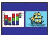
■ Display a sub screen (PIP function)
Another image can be added in smaller size (referred as sub screen in this manual) to the projected image (referred as main screen).
- Press the remote control's PIP button.
A sub screen is displayed in the currently projected image (main screen). To swap the main and sub screens, press the remote control's SWAP button.
To hide the sub screen, press the PIP button again.
Remote Control
Notes
• Sound of the main screen is output.
- Input select, display position and size of the sub screen can be changed in the PIP menu.
- Operating a function other than Mute, Freeze and volume control will release PIP mode.
- If you use this function on commercial video software, broadcast or cable-broadcasting except for the purpose of your private viewing and listening, it may infringe the copyright protected by the copyright laws.
■ Sub screen setting
Pressing the MENU button while the sub screen is displayed displays the PIP menu.
This menu sets up the sub screen.
To hide the menu, press the RETURN button.
| Item ☑ Yes Option | |
| Sets the sub screen size.Large ➕ ➤ Medium ➕ ➤ Small | |
| Sets display position of the sub screen. | |
| Selects the input source for the sub screen.When the main screen is input from computer or Y/PB/PR:Press ➕ or ➤, toggle the input with ➕ and fix selection with ➕.Video/S-videoWhen the main screen is input from video or S-video:Press ➕ or ➤, toggle the input with ➕ and fix selection with ➕.Computer (1) (Digital) / Y/PB/PR (1) (Digital) / Computer (1)(Analog) / Y/PB/PR (1) (Analog) / Computer (2) / Y/PB/PR (2) /Computer (3) / Y/PB/PR (3) |
■ Displaying two screens (SPLIT function)
This function displays two screens at a time.
- Press the remote control's SPLIT button.
The projected image moves to the left (main screen), and a new image is displayed to the right (sub screen). To switch the sub and main screens, press the remote control's SWAP button.
To hide the sub screen, press the SPLIT button again.
Remote Control
Notes
• Sound of the main screen is output.
- Size of the screens and input source of the sub screen can be changed in the SPLIT menu.
- Compared with the main screen, the sub screen may suffer some slight image degradation.
- Operating a function other than Mute, Freeze and volume control will release the SPLIT mode.
- If you use this function on commercial video software, broadcast or cable-broadcasting except for the purpose of your private viewing and listening, it may infringe the copyright protected by the copyright laws.
■ SPLIT function setting
Pressing the MENU button while two screens are displayed displays the SPLIT menu. This menu sets up both screens.
To hide the menu, press the RETURN button.
| Item √s √ption | |
| Size | Sets size of both screens. |
| Sub Input | Selects the input source for the sub screen.When the main screen is input from computer or Y/PB/PR:Press 📄 or 🔥, toggle the input with 🔥 and fix selection with 🔥.Video/S-videoWhen the main screen is input from video or S-video:Press 📄 or 🔥, toggle the input with 🔥 and fix selection with 🔥.Computer (1) (Digital) / Y/PB/PR (1) (Digital) / Computer (1)(Analog) / Y/PB/PR (1) (Analog) / Computer (2) / Y/PB/PR (2) /Computer (3) / Y/PB/PR (3) |
Note
- To enlarge the screen fully, select [Full] for [Size].
Using handy features (Continued)
■ Screen combination of PIP and SPLIT functions
| Group Input signal | |
| A | Computer (1) (Digital) / Y/PB/PR (1) (Digital) |
| Computer (1) (Analog) / Y/PB/PR (1) (Analog) | |
| Computer (2) / Y/PB/PR (2) | |
| Computer (3) / Y/PB/PR (3) | |
| B | Video |
| S-video | |
For PIP function
A: Main screen, B: Sub screen
A: Sub screen, B: Main screen
You cannot display two screens of the same group in the PIP mode.
For SPLIT function
A. B or B, A is available
You cannot display two screens of the same group in the SPLIT mode.
■ Password function
When the password function is added and [Password] is set to [On], image projection requires an entry of the preset password at power-on.
To add the password function, perform the following procedure:
(The password function, once added, cannot be deleted. Set [Password] to [Off] if you do not want to use it after addition.)
① Set the projector to the operating status or the standby mode.
② Keep pressing the ① button for about 10 seconds until a beep sounds.
The password function is added when the steps up to here have been completed. It is also added to the Default setting menu.
● How to set password (from [Off] to [On])
① Select [Password] in the Default setting menu and press the 📄 button.
The password setting confirmation screen is displayed. ([OK] or [Cancel])
② Select [OK] and press the button.
The password entry screen is displayed.
③ Enter a four-digit number for the password using numeric keys of the remote control.
The input number appears as [****].
④ Re-enter the same password for confirmation.
When the password is confirmed, the setting is complete and the password becomes [On].
If the password is wrong, repeat the procedure from step 2.
How to operate when password is [On]
① Turn on the power.
② The lamp lights and the password entry screen appears.
③ Enter the password using numeric keys of the remote control.
If the entered password is correct, the start-up screen appears and the projector goes into normal operation. If the password is wrong, a message appears to prompt you to re-enter the password. If you enter a wrong password for more than 5 times, the projector will automatically power off and enter standby mode.
● How to cancel password (from [On] to [Off])
① Select [Password] in the Default setting menu and press the 📄 button.
The password entry screen is displayed.
② Enter the password using numeric keys of the remote control.
③ The password cancel confirmation screen is displayed. ([OK] or [Cancel])
④ Select [OK] and press the button.
The [Password] is canceled and becomes [Off].
Note
- The password entry screen appears when the power is turned back on only after the main power switch is turned off or the power cord is unplugged.
If you forgot the password, please inquire your dealer.
Using the menus
You can call up on-screen menus, and conduct a number of adjustments and settings using the operation buttons p.16 on the control panel (main unit side) and remote control.
■ How to use the menus
The menu shown below is for operation instructions purposes and might differ from the actual display.
- Press the MENU button Display the Setting display menu.
2. Select a Category
Select a category by using 🔊. There are following five categories:

Image adjustment menu


Display setting menu


Default setting menu


Control setting menu


Status display menu

Displays the current adjustments and settings of selected category. Item shown with gray cannot be adjusted with the current input source.
- Adjustments & Settings Press 📁 or ▼ to open the menu.
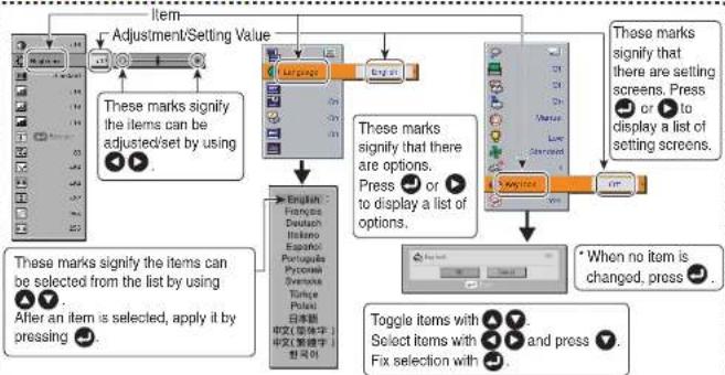
flowchart
graph TD
    A["Item"] --> B["Adjustment/Setting Value"]
    B --> C{These marks signify the items can be adjusted/set by using}
    C --> D["English: French, Dutch, Italian, Spanish, Portuguese, Japanese, Chinese (中文/英文)"]
    D --> E["To specific items selected from the list by using"]
    E --> F["After an item is selected, apply it by pressing"]
    F --> G["Select items with press and press"]
    G --> H["Fix selection with press"]
    H --> I["Toggle items with press and press"]
    I --> J["When no item is changed, press"]
    J --> K[Press or to display a list of setting screens. Press or to display a list of setting screens. Press or to display a list of setting screens. Press or to display a list of setting screens. Press or to display a list of setting screens. Press or to display a list of setting screens. Press or to display a list of setting screens. Press or to display a list of setting screens. Press or to display a list of setting screens. Press or to display a list of setting screens. Press or to display a list of setting screens.<nl>
The figure shows displays given for operation instructions purposes. As the display may differ depending on the item, use the following pages as a reference.
-
Back RETURN button
-
End Press the MENU button or RETURN button. (The menu disappears 30 seconds after the last operation.)
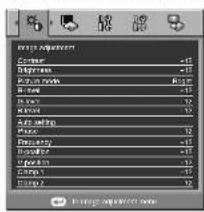
■ The image adjustment menu
Use this menu to set or adjust image-related items. Items that can be set or adjusted are marked with "Yes", and those that cannot be marked with "No". (When an item is masked, it indicates that you cannot select for the current input.)
| Item ▲ ▼ | Description | Digital (DVI) | Arakg | D-SUB(BNC) | Video | S-video | ||
| RGB | Y/PB/P= | RGB | Y/PB/PR | ||||
| Contrast Adjust the | image contrast. Yes Yes Yes Yes Yes Yes Lower ▲ ▲ Higher | ||||||
| Brightness Adjust the brightness of the image. Yes Yes Yes Darker ▲ ▲ Brighter | Yes Yes | Yes | |||||
| Color | Adjust the color of the image. Lighter ▲ ▲ Deeper | No | Yes | No | Yes | Yes | Yes |
| Tint1 | Adjust the tint of the image color. Reddish ▲ ▲ Greenish | No | No | No | No | Yes | Yes |
| Sharpness | Adjust the sharpness of the image. Softer ▲ ▲ Sharper | No | Yes | No | Yes | Yes | Yes |
| Noise reduction2 | Set the function to reduce screen noise. On (Enable) ▲ ▲ Off (Disable) | No | Yes | No | Yes | Yes | Yes |
| Picture mode | Press ▲ Toggle the picture mode with ▲ ▲ Bright/Standard/True color | Yes | Yes | Yes | Yes | Yes | Yes |
| R-level | Adjust red of the image color. Less red ▲ ▲ More red | Yes | Yes | Yes | Yes | Yes | Yes |
| G-level | Adjust green of the image color. Less green ▲ ▲ More green | Yes | Yes | Yes | Yes | Yes | Yes |
| B-level | Adjust blue of the image color. Less blue ▲ ▲ More blue | Yes | Yes | Yes | Yes | Yes | Yes |
| NTSC mode^3 | Set the black level with ▲ ▲. US :NTSC (US) mode JAPAN:NTSC (JAPAN) mode | No | No | No | No | Yes | Yes |
| Auto setting | Automatically adjusts items such as the sampling phase depending on the type of input signal. | No | No | Yes | No | No | No |
| Phase | Adjust with ▲ ▲ to eliminate flicker. | No | No | Yes | No | No | No |
| Frequency | Adjust with ▲ ▲ to eliminate periodic patterns and flickering when many vertical lines appear on the screen. | No | No | Yes | No | No | No |
| H-position | Adjust the horizontal position of the image. Move left ▲ ▲ Move right | No | No | Yes | No | No | No |
| Item ▶ ▼ | Description | Digital (DVI) | Araog ID-SUB(BNC) | Video | S-video | ||
| RGB | Y/PB/PR | RGB | Y/PB/PR | ||||
| Adjust the vertical position of the image.Move down ▶ ▶ Move up | No | No | Yes | No | No | No | |
| Adjusts the clamp pulse position.Lower ▶ ▶ Higher | No | No | Yes | No | No | No | |
| Adjusts the clamp pulse width.Narrower ▶ ▶ Wider | No | No | Yes | No | No | No | |
| Reduce noise on the screen.Adjust with ▶ ▶. | Yes | Yes | No | No | No | No | |
*1: [Tint] and [NTSC mode] can be displayed and adjusted only when the video signal is set to [NTSC] and [NTSC4.43].
*2: [Noise reduction] may not work depending on signal type.
*3: [NTSC mode] is set to JAPAN when the language is set to Japanese. It is set to US for other languages.
■ The display setting menu
Use this menu to set screen display-related items.
(The items in gray color cannot be set with the current input selection.)
 |
Detailed description
[Screen size]
If "Thru" is selected for [Screen size], portions exceeding the native resolution (1024 × 768 pixels) will not appear on the screen. Note that for RGB signals with clock frequency 140MHz or lower, all input pixel signals are sampled. However, if the clock speed is higher than this, the RGB pixel signal is thinned before sampling.
- If you use the screen size setting function on commercial video software, broadcast or cable-broadcasting programs to display images with the varying aspect ratio except for the purpose of your private viewing and listening, it may infringe the copyright protected by the copyright laws.
Using the menus (Continued)
[Background]
• T OSHIBA is set for [Logo] by factory setting.
- If user's logo has been registered, it is displayed when [Logo] is set for background.
[Start-up screen]
If user's logo has been registered and this setting is [On], the logo is displayed at start-up.
[User logo]
Registers a part of the image that is input from computer and displays it as a logo at start-up and when no signal is input.
How to register user logo
① Select [User logo] in the Display setting menu, and press the 📄 or ⏻ button.
② Select
③ The registration area is displayed for confirmation. Select [OK] or [Cancel] and press the ⏻ button.
- If the picture does not fall within the area, operate the computer to scroll the screen.
4 Press the button to register.
⑤ Registration starts.
- A message is displayed while registration is in process.
Notes
- Y ou can register a logo from computer input only.
- The area that can be registered is 512 × 384 dots at the center of the screen. To register a company logo, prepare the image within the limit.
- Only one logo can be registered. When a new image is registered, the old one is erased.
- The time needed to register or display the image varies depending on the data size.
- If you use this function on commercial video software, broadcast or cable-broadcasting except for the purpose of your private viewing and listening, it may infringe the copyright protected by the copyright laws.
Select the size of the registered logo (except during the PIP and SPLIT modes).
■: Displays the registered image in original size at center of the screen.
■: Displays the registered image by enlarging fully in the screen.
(As processed digitally, the image quality is degraded.)
Sets background color when [Center] is selected for the logo display mode.
You can preview the registered logo.
You can reset the registered logo, display style and background to the factory setting. (The logo set for the start-up screen and background is reset.)
Using the menus (Continued)
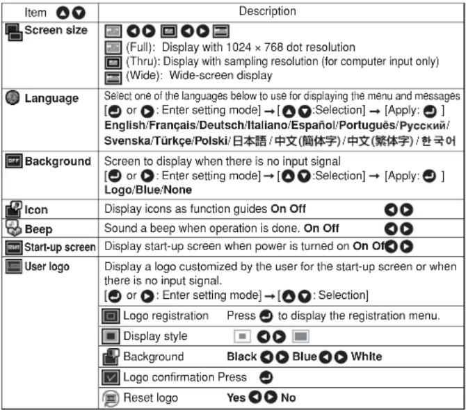
■ The default setting menu
This menu shows placement status and other settings.
| Item | Description |
| Sets projection mode in accordance with Placement Style. p.22(Standard) [Rear] (Rear ceiling) | |
| When projecting on a non-screen surface, select a color in accordance with the projecting surface.Press and switch with and Off/Green/Black/Brown/Blue/Beige | |
| Set the time to wait for the power to be turned off after the last operation is made with no input signal.Press and switch with and Off (not turned off)/1 min./5 min./10 min./30 min./60 min. | |
| Set whether the input with signals is only selected or not.On Off | |
| Sets whether to turn on the power when the ON/STANDBY button is pressed (Manual), or when the main power switch is turned on (Auto). Manual Auto | |
| Sets the lamp power.Low Standard | |
| Sets the cooling fan speed.Standard High | |
| When two or more projectors are used and controlled by the remote control respectively, this menu sets the code for the projector and the remote control.[or : Enter setting mode] → [: Select item] → [:Select from 1, 2, 3, 4] → [:Confirm] → [:Select OK to end]Press [Cancel] to return. | |
| Lock the control panel buttons.[or : Enter setting mode] → [: Select item] → [:Select On/Off] → [:Confirm] → [:Select OK to end]Press [Cancel] to return. | |
| Press . (The password and user logo are not reset.) Resets all adjustments and settings to their factory settings. Yes No | |
| Password Off OnWhen [Password] is [On], the Password Setting screen is displayed. |
Detailed description
[Blackboard mode]
Projects the image in colors more like projecting on a screen.
Note
- The projected image may differ depending on the type, color, and material of the blackboard and wall even if the selected color is the same as the projected screen.
[Auto Input search]
[On]: Automatically searches the signals that can be projected, and switches input from the connected device that outputs the signals each time the INPUT button is pressed. The input from the connected device that outputs no signals is skipped.
[Off]: Displays the Input select menu.
Toggle with ▼ 4 buttons and press 📊 button. (The input without signals can be selected.)
Input select menu
| Input select | |
| ● Computer (1) (Digital) | |
| ○ Y/Ps/Pr(1) (Digital) | |
| ○ Computer (1) (Analog) | |
| ○ Y/Ps/Pr(1) (Analog) | |
| ● Computer (2) | |
| ○ Y/Ps/Pr(2) | |
| ○ Computer (3) | |
| ○ Y/Ps/Pr(3) | |
| ● Video | |
| ○ S-video |
●/○ shows whether signal is input or not.
[Power on]
Note that if [Power on] is set to [Auto], then if the main power switch is ON when power is restored after a power outage, the projector will come on.
[Lamp power]
When [Lamp power] is set to [Low], the screen becomes a little darker, but the cooling fan noise gets quieter.
[Fan mode]
Setting [Fan mode] to [High] increases the cooling fan speed. Set this option to use the projector, for example, at high altitude (over 1,500 meters above sea level).
[Remote control]
Sets a remote control code from 4 types. You can set each code respectively for up to 4 projectors. The factory setting is [1].
To switch codes, set the same code for the projector and the remote control.
A remote control code is applied after the setting is done.
- Y ou cannot operate the remote control if the codes of the projector and the remote control do not match.
- Remote control code setting for remote control
Remove the battery cover and set the same remote control code switch as the projector. p.16 (Use a screwdriver with thin tip to set.)
[Key lock]
Protect from operating errors by locking on the control panel buttons of the projector. (The remote control operations are available.)
Control panel operations are locked after the setting is done.
- To release the key lock, press the control panel's RETURN button for 10 seconds. The key lock is released with a beep sound.
Using the menus (Continued)
■ The control setting menu
This menu sets items regarding wired LAN.
By this setting, you can transmit operation status messages from the projector to the specified E-mail address.
| Item | Description |
| Wired LAN | [●: Wired LAN setting] → [▲●: Select item] |
| Projector name: Enter a character string (0 to 64 characters) using numeric keys of the remote control. | |
| DHCP: Use ▶▶ Not use | |
| IP address: Enter a character string using numeric keys of the remote control. | |
| Subnet mask: Enter a character string using numeric keys of the remote control. | |
| Gateway: Enter a character string using numeric keys of the remote control. | |
| Confirm: [OK ▶▶ Cancel] → ▶ | |
| [●: E-mail setting] → [▲●: Select item] | |
| Status notification: On ▶▶ Off | |
| SMTP server: Enter a character string using numeric keys of the remote control. | |
| Port number: Enter a character string using numeric keys of the remote control. | |
| Destination address: Enter a character string using numeric keys of the remote control. | |
| Confirm: [OK ▶▶ Cancel] → ▶ | |
| PJLink | [●: PJLink setting] → [▲●: Select item] |
| PJLink authentication: On ▶▶ Off | |
| Password: Enter a desired character string (1 to 32 characters) using numeric keys of the remote control. | |
| Confirm: [OK ▶▶ Cancel] → ▶ |
Detailed description
[Wired LAN]
- You cannot set a projector name starting with ERR.
When
[Email]
[PJLink]
Precautions
- When purchased,
- If you forget a password, set it again.
Character entry
Enter characters using numeric keys of the remote control.
The character is entered with a beep sound if the beep sound is set to [On].
| Character entry mode | ||
| Remote control button | Items using characters, numbers, and symbols (e.g., projector name and destination address) | Number only |
| “1” “.” “@” “-” | “1” | |
| “2” “A” “B” “C” “a” “b” “c” | “2” | |
| “3” “D” “E” “F” “d” “e” “f” | “3” | |
| “4” “G” “H” “I” “g” “h” “l” | “4” | |
| “5” “J” “K” “L” “J” “K” “l” | “5” | |
| “6” “M” “N” “O” “m” “n” “o” | “6” | |
| “7” “P” “Q” “R” “S” “p” “q” “r” “s” | “7” | |
| “8” “T” “U” “V” “I” “u” “v” | “8” | |
| “9” “W” “X” “Y” “Z” “w” “x” “y” “z” | “9” | |
| “0” “space!”#$%&( )“+,-;-;<=->?@[ \ }_ { | }~ | “0” | |
| CULUM | Deletes one character. | Deletes one character. |
Using the menus (Continued)
■Displaying Information (Status display)
This displays information about the input signal, lamp use time, LAN connection status, etc.
"Yes": displayed, "No": not displayed
| Item Description | Computer | Y: P_B/P_H Video S-video | |||
| Projector | |||||
| Input Input source name Yes Yes Yes Yes | |||||
| Mode name | RGB input mode [Note 1] | Yes | No | No | No |
| Resolution | Resolution (in dots) | Yes | No | No | No |
| Frequency | Sync frequency | Yes | No | No | No |
| Sync Sync signal polarity [Note 2] | Yes | No | No | No | |
| Signal format | Y/P_B/P_R signal format | No | Yes | No | No |
| Video mode | Color method of video signal | No | No | Yes | Yes |
| Lamp time | Time of lamp use [Note 3] | Yes | Yes | Yes | Yes |
| Lamp reset count | The count for lamp replacement | Yes | Yes Yes | ||
| Total time | The total time that this projector is used. | Yes | Yes | Yes | Yes |
| Version | Firmware version [Note 4] | Yes | Yes | Yes | Yes |
| Wired LAN | |||||
| Connection status | Displays connection status of LAN. | Yes Yes | Yes Yes | ||
| IP address | Displays the IP address. | Yes Yes | Yes Yes | ||
| Subnet mask | Displays numeric value of subnet mask. | Yes | Yes | Yes | Yes |
| Gateway | Displays numeric value of gateway. | Yes | Yes | Yes | Yes |
| MAC address | Displays MAC address of the projector. [Note 5] | Yes | Yes | Yes | Yes |
| PJLink class | PJLink version | Yes | Yes | Yes | Yes |
Notes
1: The mode of supported RGB signals p.56 is shown.
2: Sync signal polarity shown as P (positive) or N (negative) for [H/V].
3: Displays [Lamp time] as a measure of when the lamp should be replaced. (Cannot be used as a counter of guaranteed lamp time.) When the displayed time approaches 1,500 hours, consult with a store about getting a TLPLW13 replacement lamp (sold separately) prepared.
4: [Version] shows the version of the projector's internal control program. This version is referred to for customer service, etc.
5: In case that "----" appears for MAC address, please contact your dealer.
Note
- The displayed information will not be refreshed if the status changes. To refresh the information, dismiss the display, then display it again. The information regarding wired LAN is refreshed every time it is displayed.
About lamp
The product's light source is a mercury lamp that lights at increased internal pressure. Be sure to fully understand the following characteristics of the lamp and handle it with extreme care.
- The lamp may burst with a loud noise due to impact or deterioration, or fail to light at the expiration of its life.
- How long it takes before the lamp bursts or the life expires may vary greatly by lamp. Some may burst shortly after first use.
- Burst is likely to happen if the lamp is used after the replacement period has elapsed.
- When the lamp bursts, the broken pieces of glass may get inside the product or be released outside from the openings for ventilation.
- When the lamp bursts, a slight amount of mercury gas enclosed in the lamp along with glass dust may be released from the openings for ventilation.
- Immediately replace the lamp when a sign appears on the screen.
- When the replacement time approaches, a message will appear on the screen.
- The risk of burst will increase if the lamp is continuously used without being replaced.
- F frequently check the used hours and prepare spares when the replacement time approaches. (Refer to "Status display". p.48)
■ When the lamp is broken
- If glass components, including a lamp and a lens, should break, handle the broken pieces with care to avoid injury and contact your dealer for repair service.
- In the event of lamp burst, unplug the product from the wall outlet, leave and completely ventilate the room. Then, thoroughly clean the area around the projector and discard any edible items placed in that area.
- When the lamp bursts, consult a doctor if glass dust or mercury gas gets into your eyes or you breathe it.
Lamp replacement
A lamp is consumable supplies. If used for extended periods, images will appear dark, and the lamp could burn out. This is characteristic of a lamp, and is not malfunction. (The lifetime of the lamp depends on condition of use.) If this happens, replace it with a new one.
WARNING
- If the projector is mounted on the ceiling, it is recommended to use your Toshiba dealership when the lamp has to be exchanged.
Uncovering the lamp while the projector is mounted on a ceiling may lead to a danger of damage from falling pieces of glass if the lamp is broken. Besides, working at high elevations can also be hazardous. Do not attempt to replace the lamp by yourself. - When replacing, always use lamp "TLPLW13" (sold separately).
CAUTION
- If you have been using the projector, the lamp will be very hot, and may cause burn injuries. Wait for the lamp to cool (for longer than 1 hour) before replacing it.
- If the lamp should break, please handle with care to avoid injury due to broken pieces and contact your dealer for repair service.
Lamp replacement (Continued)
① Unplug power cord.
② Wait until lamp is sufficiently cooled.
Wait for at least 1 hour.
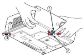
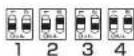
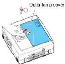
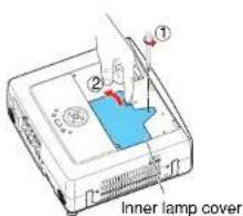
③ Remove the outer lamp cover.
Loosen the two screws, raise the outer lamp cover with your fingers as shown to remove the outer lamp cover. Use care to avoid any damage to nails and/or tip of your finger(s). If you have any difficulty in removal, you can use a screwdriver or any other smaller tool for your convenience.
④ Remove the inner lamp cover.
Loosen the screw to remove the inner lamp cover.
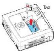
⑤ Pull out the lamp.
Loosen the three lamp locking screws, pull up the handle, and press the tab to remove the lamp.
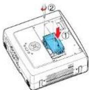
⑥ Mount the new lamp.
Align the orientation, press down the new lamp until the bottom is reached, and lock in place using the three lamp locking screws.
3
4
5
6
⑦ Replace the inner lamp cover.
Tighten the screw loosened in step 4 until the inner lamp cover is no longer loose.
8 Replace the outer lamp cover.
Align the cover, and press it in, then tighten the screws loosened in step ③ until the outer lamp cover is no longer loose. (Be sure to replace the outer lamp cover.)
⑨ Reset the lamp timer.
See the lamp's manual for instructions on resetting the lamp timer.
Notes and Precautions
- The Lamp time item in the Status display menu indicates the time of lamp use (as a rough guide). p.48
- It is recommended that the lamp be replaced after 1,500 hours of use. When [Lamp time] reaches 1,500 hours, the 📋 icon and a message will appear with a beep sound. {After 1,500 hours, they will appear when the power is on at the first time every 100 hours.} This display disappears when you press the 📋 button.
- Attach the outer lamp cover correctly so that it is not loose. If it is not attached correctly, the projector may fail to be powered on or the lamp may fail to come on.
• Always replace the lamp with a new one. - The lamp is made out of glass. Do not touch the glass surface with your bare hands, bang it, or scratch it. (Dirt, jolts, scratches and the like could break the lamp.)
Used Lamps
This projector's lamps contain trace amounts of environmentally harmful inorganic mercury. Be careful not to break used lamps, and dispose of them in accordance with local regulations.
Lens and main unit cleaning
WARNING
- Request cleaning and maintenance of a ceiling-mounted unit from your projector dealership. Attempting to clean/replace the lamp at a high site by yourself may cause you to fall down, thus resulting in injury.
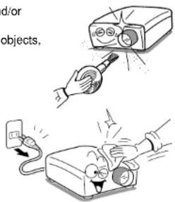
■ Lens cleaning
- Clean the lens with a commercially available blower and/or lens cleaner.
- The lens is easily scratched, so do not rub it with hard objects, or strike it.
■ Main unit cleaning
- Clean the main unit after unplugging the power cord.
- Wipe dirt off the main unit gently with a soft cloth.
- Do not wipe the main unit with a damp cloth. Doing so may allow water to get inside, resulting in an electric shock or failure.
- Do not use benzene, thinner and the like as they may deform or discolor the unit or damage the paint surface.
- When using a chemically treated cloth, follow the precautions included with the cloth.
Trouble indications
The indicator lights and a beep sound inform you of internal abnormalities.
 | No power Problem with projectorUnplug the power cord, and contact your dealer. |
 (Red lit)(Red lit) (Red lit)(Red lit) | Lamp went out during use, or won't come on Lamp temperature is high so that it is difficult to turn on, the lifetime of the lamp has ended or the projector is malfunctioning.Unplug the power cord and wait for a short while, then turn the power back on.If a lamp burns out, replace it with a new one. ÷ After approx. one minute of abnormal display, the projector returns to the standby state waiting for internal cool down. |
 (Green lit)Or (Orange lit)(Red lit) (Green lit)Or (Orange lit)(Red lit) | Power went out during use Internal overheating, or the outside temperature is too high.Place the projector so that the air intake and exhaust are not blocked.Unplug the power cord and wait for a short while, then turn the power back on. ÷ The icon will appear before the power goes out. ÷ After approx. one minute of abnormal display, the projector returns to the standby state waiting for internal cool down. |
 (Red lit) (Red lit) | Power went out during use Problem with internal cooling fan.Unplug the power cord, and contact your dealer. ÷ The icon will appear before the power goes out. ÷ After approx. one minute of abnormal display, the projector returns to the standby state waiting for internal cool down. |
 (Orange flashing)(Red lit) (Orange flashing)(Red lit) | Power went out during use, or power won't come on The lamp cover is not properly attached.Unplug the power cord, and reattach the lamp cover.p-51 ÷ After approx. one minute of abnormal display, the projector returns to the standby state waiting for internal cool down. |
 (Green flashing)(Red lit) (Green flashing)(Red lit) | Power went out during use Problem Inside the projector.Unplug the power cord and wait for a short while, then turn the power back on.If the above action will not clear the problem, unplug the power cord, and contact your dealer. ÷ The icon will appear before the power goes out. ÷ After approx. one minute of abnormal display, the projector returns to the standby state waiting for internal cool down. |
Before calling service personnel
If you think something is wrong, check the followings before contacting customer service. Please see "Trouble indications" p.53 as well.
| If This Happens | Check |
| No power | • Is the power cord plugged in? Is it connected to the projector?• Is the main power switch turned on? p.26• Is the outer lamp cover attached properly? p.50 |
| Power goes out during use | • Is the ambient temperature high? p.53• Is the air intake or air exhaust blocked? p.53 |
| No picture | • Is the projector turned on? (When [Auto input search] is [Off]) p.45• Is the mute function on? p.32• Is the brightness setting minimized? p.39• Are the connections set up correctly? p.24• Are all the connected devices functioning properly? |
| No audio | • Is the mute function on? p.32• Is the volume setting minimized? p.29• Are the connections set up correctly? p.24• Are all the connected devices functioning properly? |
| Picture not displayed correctly | • Is the input signal supported by the projector? p.56 , p.57• Is there something generating an abnormal video signal, for instance the video tape? |
| Picture blurred Part of picture out of focus | • Is the lens dirty? p.52• Is the lens focus adjusted optimally? p.29• Is the projection distance within the projector's supported range? p.23• Is the projector's screen placement angle tilted too far? p.23• Are the sharpness or sampling phase adjustments off? p.39 |
| Image is dark | • Are the brightness or contrast adjustments off? p.39• Is the lamp nearing the end of its service life? p.48 |
| Colors too light Bad shading | • Are the color, tint, R-level, G-level, or B-level adjustments off? p.39• Is the screen dirty?• Is the blackboard mode set properly? p.44• Is the lamp nearing the end of its service life? p.48 |
| Control panel key doesn't work | • Is the key lock function on? p.44 |
| Remote control doesn't work | • Is the remote control ON/OFF switch set off? p.20• Is the remote control code identical with the projector's code? p.45• Are the remote control's batteries drained?• Are the batteries inserted into the remote control correctly? p.20• Is the remote control being used within the effective range? p.20• Are there any obstructions between the remote control and projector?• Are there any fluorescent or other bright lights shining at the projector's infrared remote sensor? |
Specifications
■List of general specifications
| Item Specification | on | |
| Consumption Power 390 W | ||
| Weight 4.9 kg | ||
| External Dimensions (including protruding parts) | 340 × 115 × 314 mm (W × H × D) | |
| Cabinet material PC+ABS resin and ABS resin | ||
| Conditions for usage environment | Temp: 5°C to 35°C; relative humidity: 30% to 70% | |
| Display pixels | 1 chip DMDTM | |
| Picture elements | 786,432 pixels (1024H × 768V) | |
| Lens Zoom lens F=2.4-2.6 f=23-27.6 mm | ||
| Lamp High-pressure mercury lamp (300 W) | ||
| Projection screen size 33-30 inches | ||
| Projection distance 1.29-12 m | ||
| Speaker | 4 W + 4 W (stereo) | |
| Connection terminal | CONTROL terminal | LAN: 10BASE-T/100BASE-TX |
| RS-232C: Mini DIN 8 pin | ||
| COMPUTER(Y/PB/Pr) 1 IN terminal | DVI-I: Analog RGB / Digital RGB / Y/Pa/Pr (dual use) | |
| AUDIO: 3.5mm dia. stereo mini-jack, 1.5 V (rms) | ||
| COMPUTER(Y/PB/Pr) 2 IN terminal | Mini D sub 15 pin Analog RGB / Y/Pb/Pr (dual use) | |
| AUDIO: 3.5mm dia. stereo mini-jack, 1.5 V (rms), 22 kΩ or more | ||
| COMPUTER(Y/PB/Pr) 3 IN terminal | G/Y: BNC Jack G: 0.7 V (p-p), 75Ω, Y: 1 V (p-p), 75Ω | |
| B/Pb: BNC Jack 0.7 V (p-p), 75Ω | ||
| R/PR: BNC Jack 0.7 V (p-p), 75Ω | ||
| HD (Horizontal sync signal): BNC Jack TTL level (Pos/neg polarity) | ||
| VD (Vertical sync signal): BNC Jack TTL level (Pos/neg polarity) | ||
| AUDIO: 3.5mm dia. stereo mini-jack, 1.5 V (rms), 22 kΩ or more | ||
| VIDEO IN terminal | S-VIDEO: Mini DIN 4 pin | |
| AUDIO (L/R): RCA Pin Jack × 2, 1.5 V (rms), 22 kΩ or more | ||
| VIDEO: RCA Pin Jack, 1 V (p-p), 75Ω | ||
| AUDIO (L/R): RCA Pin Jack × 2, 1.5 V (rms), 22 kΩ or more | ||
| MONITOR OUT terminal | Mini D sub 15 pin RGB / Y/Pb/Pr (dual use) | |
| AUDIO OUT terminal | 3.5mm dia. stereo mini-jack, 1.5 V (rms), 22 kΩ or more | |
Notes
- This model complies with the above specifications.
- Designs and specifications are subject to change without notice.
- This model may not be compatible with features and/or specifications that may be added in the future.
■Separately sold product
Replacement Lamp
Model TLPLW13
Specifications (Continued)
■ List of supported signals (RGB signals)
This projector supports the following RGB signals. Note, however, that depending on the computer model, the screen may show flicker or streaking. Please adjust the projector if this happens.
| Resolution | Mode | Refresh rate (Hz) | H-frequency (kHz) | Clock (MHz) |
| 720 x 400 | 720x400_85 | 85.039 | 37.927 | 35.500 |
| 640 x 480 | VGA_60 | 59.940 | 31.469 | 25.175 |
| VGA_72 | 72.809 | 37.861 | 31.500 | |
| VGA_75 | 75.000 | 37.500 | 31.500 | |
| VGA_85 | 85.008 | 43.269 | 36.000 | |
| 800 x 600 | SVGA_56 | 56.250 | 35.156 | 36.000 |
| SVGA_60 | 60.317 | 37.879 | 40.000 | |
| SVGA_72 | 72.188 | 48.077 | 50.000 | |
| SVGA_75 | 75.000 | 46.875 | 49.500 | |
| SVGA_85 | 85.061 | 53.674 | 56.250 | |
| 832 x 624 | MAC16" | 74.550 | 49.725 | 57.283 |
| 1024 x 768 | XGA_60 | 60.004 | 48.363 | 65.000 |
| XGA_70 | 70.069 | 56.476 | 75.000 | |
| XGA_75 | 75.029 | 60.023 | 78.750 | |
| XGA_85 | 84.997 | 68.667 | 94.500 | |
| MAC19" | 74.700 | 60.134 | 79.857 | |
| 1152 x 864 | SXGA1_75 | 75.000 | 67.500 | 108.000 |
| 1280 x 960 | QuadVGA_60 | 60.000 | 60.000 | 108.000 |
| QuadVGA_85 | 85.002 | 85.938 | 148.500 | |
| 1280 x 1024 | SXGA3_60 | 60.020 | 63.981 | 108.000 |
| SXGA3_75 | 75.025 | 79.976 | 135.000 | |
| SXGA3_85 | 85.024 | 91.146 | 157.500 | |
| *1400 x 1050 | SXGA+ | 59.978 | 65.317 | 121.750 |
| *1600 x 1200 | UXGA_60 | 60.000 | 75.000 | 162.000 |
| UXGA_65 | 65.000 | 81.250 | 175.500 | |
| UXGA_70 | 70.000 | 87.500 | 189.000 | |
| UXGA_75 | 75.000 | 93.750 | 202.500 | |
| UXGA_85 | 85.000 | 106.250 | 229.500 |
* Depending on the model of computer, the image may not be displayed properly with the DVI input.
Note
- Signals whose resolution exceeds the native resolution (1024 × 768 pixels) will be compressed. For this reason, some information may be lost, or image quality may be affected.
■ List of supported signals (Y/P B /P R signals)
| Signal format fh(kHz) fv(Hz) | |
| * 480i(525i)@60Hz 15.73 59.94 | |
| 480p(525p)@60Hz 31.47 59.94 | |
| * 576i(625i)@50Hz 15.63 50.00 | |
| 576p(625p)@50Hz 31.25 50.00 | |
| 720p(750p)@60Hz 45.00 60.00 | |
| 720p(750p)@50Hz 37.50 50.00 | |
| 1080i(1125i)@60Hz 33 75 60.00 | |
| 1080i(1125i)@50Hz 28 13 50.00 |
* D VI digital input is not supported.
■ List of supported signals (Video, S-Video signals)
| Video mode fh(kHz) | fv(Hz) | fsc(MHz) | |
| NTSC | 15.73 | 60 3.58 | |
| PAL | 15.63 | 50 | 4.43 |
| SECAM | 15.63 | 50 | 4.25 or 4.41 |
| PAL-M | 15.73 | 60 3.58 | |
| PAL-N 15.63 | 50 3.58 | ||
| PAL-60 | 15.73 | 60 4.43 | |
| NTSC4.43 | 15.73 | 60 4.43 |
■ Pin assignment of COMPUTER-2 & MONITOR terminals
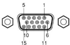
Mini D sub 15 Pin connector
Input Signal
- RGB input
RGB signals: 0.7V (p-p) 75 Ω
Horizontal sync signal: TTL level (Pos/neg polarity)
Vertical sync signal: TTL level (Pos/neg polarity)
- Y/P B/PR input
Y signal: 1.0V (p-p) 75 Ω
P_B/P_R signals: 0.7V (p-p) 75 Ω
| Pin No | Pin description | |
| During RGB input | During Y/PB-PR input | |
| 1 | Video signal (R) | Color difference signal (Pn) |
| 2 | Video signal (G) | Luminance signal (Y) |
| 3 | Video signal (B) | Color difference signal (Pa) |
| 4 | GND | * |
| 5 | GND | * |
| 6 | GND (R) | GND (Pn) |
| 7 | GND (G) | GND (Y) |
| 8 | GND (B) | GND (Pn) |
| 9 | N.C | * |
| 10 | GND | * |
| 11 | GND | * |
| 12 | N.C | * |
| 13 | Horizontal sync signal | * |
| 14 | Vertical sync signal | * |
| 15 | N.C | * |
* Do not connect anything.
Specifications (Continued)
■ Pin assignment of DVI-I terminal
COMPUTER IN 1
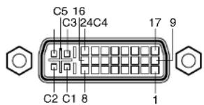
DVI digital & analog connector
Analog input signal
• Analog RGB input
RGB signals: 0.7V (p-p) 75 Ω
Horizontal sync signal: TTL level (Pos/neg polarity)
Vertical sync signal: TTL level (Pos/neg polarity)
- Y/P B /P R input
Y signal: 1.0V (p-p) 75 Ω
P_B/P_R signals: 0.7V (p-p) 75 Ω
| Pin No. | Pin description |
| 1 | T.M.D.S. data 2 – |
| 2 | T.M.D.S. data 2 + |
| 3 | T.M.D.S. data 2/4 shielded |
| 4 | T.M.D.S. data 4 – (N.C) |
| 5 | T.M.D.S. data 4 + (N.C) |
| 6 | DDC clock |
| 7 | DDC data |
| 8 | Analog vertical sync signal |
| 9 | T.M.D.S. data 1 – |
| 10 | T.M.D.S. data 1 + |
| 11 | T.M.D.S. data 1/3 shielded |
| 12 | T.M.D.S. data 3 – (N.C) |
| 13 | T.M.D.S. data 3 + (N.C) |
| 14 | +5V power source |
| 15 | GND(+5V, H Sync & V Sync) |
| Pin No. | Pin description |
| 16 | Hot plug detection |
| 17 | T.M.D.S. data 0 – |
| 18 | T.M.D.S. data 0 + |
| 19 | T.M.D.S. data 0/5 shielded |
| 20 | T.M.D.S. data 5 – (N.C) |
| 21 | T.M.D.S. data 5 + (N.C) |
| 22 | T.M.D.S. clock shielded |
| 23 | T.M.D.S. clock + |
| 24 | T.M.D.S. clock – |
| C1 | Analog video signal (R / Pr) |
| C2 | Analog video signal (G / Y) |
| C3 | Analog video signal (B / Ps) |
| C4 | Analog horizontal sync signal |
| C5 | Analog GND(R/PR,G/Y,B/Pβ) |
■ CONTROL terminal
● Pin assignment
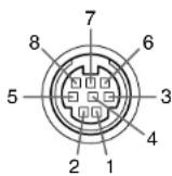
Mini DIN 8 pin connector
| Pin No. | Signal Name | Description |
| 1 | RXD | Receiving data |
| 2 | CTS | Consent to send |
| 3 | DSR | Data set ready |
| 4 | GND | Signal ground |
| 5 | RTS | Request to send |
| 6 | N.C | No connection |
| 7 | TXD | Sending data |
| 8 | GND | Signal ground |
- Interface format
1 Communication method RS-232C, 9600bps, No Parity, Data Length: 8 bits; Stop Bit Length: 1 bit
2 Communication format STX (02h) Command (3Byte) ETX (03h)
Only 1 command valid per communication.
3 Data format For input commands, only ASCII-compliant all-uppercase alphanumeric characters supported.
4 Replies Acknowledge ACK (06h) CR (0Dh) Data ... Normally ended ACK (06h) ESC (1Bh) ... Aborted No acknowledge NAK (15h)
If commands are to be sent consecutively, wait for the response from the projector before sending the next command.
● Main Commands
| Item | Command |
| Power on | PON |
| Power off | POF |
| Icon display on | MO0 |
| Icon display off | MO1 |
| Auto setting (RGB input) | PAT |
| Status display on | DON |
| Status display off | DOF |
Note
- Contact your dealer for control cable and other commands.
TOSHIBA CORPORATION
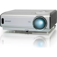
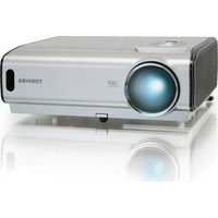
- SAFETY PRECAUTIONS
- MODEL NAME: TDP-T350
- IMPORTANT SAFETY INSTRUCTIONS
- Read Owner's Manual
- Power Sources
- Source of Light
- Ventilation
- Heat
- Water and Moisture
- Cleaning
- Power-Cord Protection
- Overloading
- IMPORTANT SAFETY INSTRUCTIONS (Continued)
- Lightning storms
- Object and Liquid Entry
- Do not place the product vertically
- Stack Inhibited
- Attachments
- Accessories
- Damage Requiring Service
- If glass components, including lens and lamp, should break, contact your dealer for repair service.
- Servicing
- Replacement Parts
- Safety Check
- Do not leave thermal-paper documents or easily deformed items on top of the unit or near the air exhaust for long periods of time.
- Do not look into the laser light source of the remote control or direct the laser pointer toward a person or a mirror.
- POWER SUPPLY CORD SELECTION
- IMPORTANT PRECAUTIONS
- Save Original Packing Materials
- Moisture Condensation
- Place and Manner of Installation
- IMPORTANT PRECAUTIONS (Continued)
- Avoid Volatile Liquid
- EXEMPTION CLAUSES
- OTHER CAUTIONS AND INFORMATIONS
- Copyrights
- Disposal
- Trademarks
- Notational Conventions Used in This Manual
- REMOTE CONTROL BATTERIES
- Caution
- Notes
- CONTENTS
- Before Using
- Preparations
- Operations
- Maintenance
- Others
- Checking the package contents
- Note
- ◆The Supplied CD-ROM
- ■ Installing Acrobat® Reader™
- ■ Viewing the manual
- Names of each part on the main unit
- Name
- : Function
- Names of each part on the control panel and remote control
- Control panel
- Remote control
- Label locations
- Parts on the rear panel
- Name : Main Function
- Preparing and using the remote control
- ■ Loading dry-cell batteries into the remote control
- ■ Operating the remote control
- Dry-cell batteries
- The remote control
- Operating a computer using the remote control
- ① Connecting a computer
- ② Operating a computer
- Placement
- Placement Styles
- WARNING
- Projection Distance and Size
- Connection
- Before connection
- Turning the power on and off
- PRECAUTION
- Basic operations
- ① Turn on the power.
- ② Select the language and the lamp power (When using the first time).
- ③ Activate the connected device.
- Press the INPUT button.
- ⑤ Projector placement angle adjustments
- ⑥ Adjusting the screen size and focus
- Adjusting the volume with the ◀▶ buttons
- Using handy features
- ■ Using auto setting (Only for analog Input from computer)
- - Press the remote control's AUTO SET button.
- ■ Correcting the keystone distortion
- ⑦ Press the KEYSTONE button.
- Adjusting vertical distortion [Auto]
- ② Press the button.
- Adjusting vertical distortion [Manual]
- Adjusting horizontal distortion [Manual]
- ③ Use the ◀▶ buttons for keystone adjustment.
- ■ Resizing image
- f Press the remote control's RESIZE ↗ button.
- Using handy features (Continued)
- ■ Display a sub screen (PIP function)
- - Press the remote control's PIP button.
- ■ Sub screen setting
- ■ Displaying two screens (SPLIT function)
- - Press the remote control's SPLIT button.
- ■ SPLIT function setting
- ■ Screen combination of PIP and SPLIT functions
- For PIP function
- For SPLIT function
- ■ Password function
- ① Set the projector to the operating status or the standby mode.
- ② Keep pressing the ① button for about 10 seconds until a beep sounds.
- ● How to cancel password (from [On] to [Off])
- Using the menus
- ■ How to use the menus
- Select a Category
- ■ The image adjustment menu
- ■ The display setting menu
- Detailed description
- [Screen size]
- Using the menus (Continued)
- [Background]
- [Start-up screen]
- [User logo]
- How to register user logo
- ■ The default setting menu
- [Blackboard mode]
- [Auto Input search]
- Input select menu
- [Power on]
- [Lamp power]
- [Fan mode]
- [Remote control]
- - Remote control code setting for remote control
- [Key lock]
- ■ The control setting menu
- [Wired LAN]
- [Email]
- [PJLink]
- Precautions
- Character entry
- ■Displaying Information (Status display)
- About lamp
- - Immediately replace the lamp when a sign appears on the screen.
- ■ When the lamp is broken
- Lamp replacement
- Lamp replacement (Continued)
- ① Unplug power cord.
- ② Wait until lamp is sufficiently cooled.
- ③ Remove the outer lamp cover.
- ④ Remove the inner lamp cover.
- ⑤ Pull out the lamp.
- ⑥ Mount the new lamp.
- ⑦ Replace the inner lamp cover.
- Replace the outer lamp cover.
- ⑨ Reset the lamp timer.
- Notes and Precautions
- Used Lamps
- Lens and main unit cleaning
- ■ Lens cleaning
- ■ Main unit cleaning
- Trouble indications
- Before calling service personnel
- Specifications
- ■Separately sold product
- Specifications (Continued)
- ■ List of supported signals (RGB signals)
- ■ Pin assignment of DVI-I terminal
- ■ CONTROL terminal
- ● Pin assignment
- - Interface format
Brand : TOSHIBA
Model : TDP-T350
Category : Vidéo-projecteur