
CCVEST14NOXGB - Instant water heater and water heater CORBERO - Free user manual and instructions
Find the device manual for free CCVEST14NOXGB CORBERO in PDF.


| Product Type | Gas Water Heater (Instantaneous) |
| Model | CCVEST14NOXGB |
| Brand | Corbero |
| Dimensions (Width x Depth x Height) | 345 x 570 x 600 mm |
| Net Weight | Approx. 15 kg |
| Power Supply | 220-240 V ~ 50 Hz |
| Electric Power Consumption | 38 W |
| Gas Type | Natural Gas (G20) or LPG (G30/G31) |
| Nominal Heat Input (Hi) | 28 kW |
| Nominal Heat Output | 25.4 kW |
| Max Flow Rate (ΔT 25°C) | 14 L/min |
| Min Start-Up Water Pressure | 0.02 MPa (2.5 L/min) |
| Max Water Pressure | 10 bar |
| Temperature Range | 35 °C to 65 °C |
| Ignition Method | Water flow automatic pulse ignition |
| Flue Duct Diameter | External 100 mm, Internal 60 mm |
| Water Connection (Inlet/Outlet/Gas) | G 1/2 |
| Degree of Electrical Protection | IPX4 |
| Control Type | Touch panel with digital display |
| Operating Modes | Normal, Auto, Eco |
| Safety Features | Flame-out, overheat, over-pressure, anti-freeze, child lock, etc. |
| Special Features | Micro-computer control, constant temperature, AI memory, low-pressure start |
| Solar System Compatibility | Yes (series connection with mixing valve required) |
| Maintenance | Annual cleaning of heat exchanger; check flue every 6 months |
Frequently Asked Questions - CCVEST14NOXGB CORBERO
User questions about CCVEST14NOXGB CORBERO
0 question about this device. Answer the ones you know or ask your own.
Ask a new question about this device
Download the instructions for your Instant water heater and water heater in PDF format for free! Find your manual CCVEST14NOXGB - CORBERO and take your electronic device back in hand. On this page are published all the documents necessary for the use of your device. CCVEST14NOXGB by CORBERO.
USER MANUAL CCVEST14NOXGB CORBERO
natural_image
Diagram of a device with a cylindrical component emitting steam, mounted on a base with two square cutouts (no text or symbols)natural_image
Technical line drawing of an electrical enclosure with internal compartments and wiring (no text or symbols)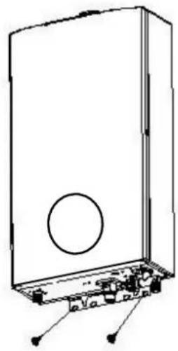
natural_image
Diagram of a device casing with internal components and mounting points (no text or symbols)Fig. 9 (Unit: mm)
natural_image
Cartoon illustration of a character with a gas cylinder and pipe, no text or symbols presentnatural_image
Cartoon character with a smiling face and raised index finger, holding a rectangular box (no text or symbols)Fig.17
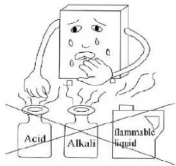
Fig.18
natural_image
Technical line drawing of an internal mechanical or electronic device with no visible text or symbols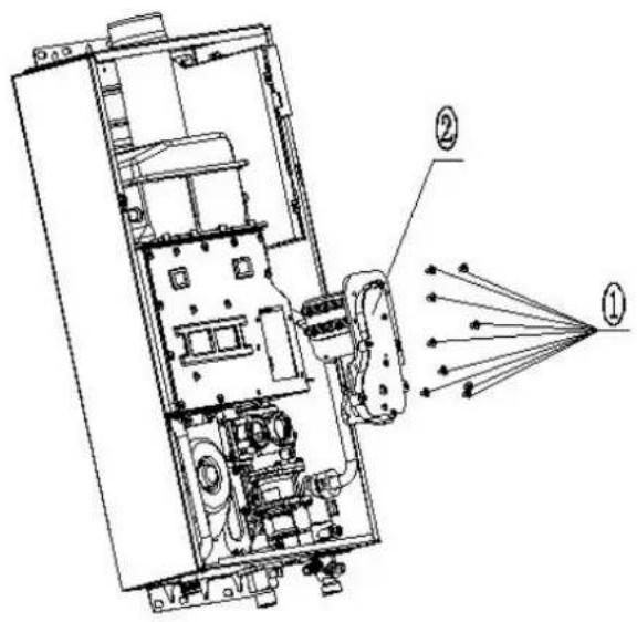
pie 2
natural_image
Technical line drawing of an internal electrical enclosure or enclosure with visible components and wiring (no text or labels)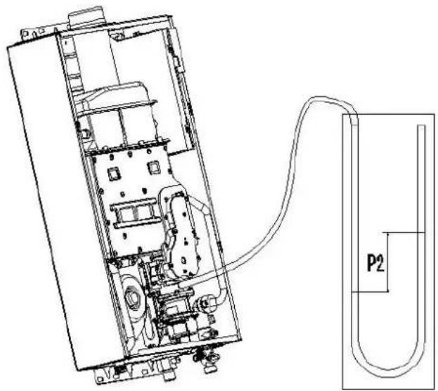
natural_image
Technical line drawing of an electronic device with internal components and a labeled connection point P2 (no text or symbols beyond label)10-12L
pie 2
natural_image
Technical line drawing of an internal combustion chamber with labeled components (no text or symbols present)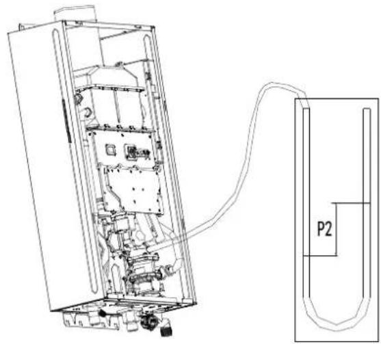
natural_image
Technical line drawing of an internal electronic device with a cable and labeled component P2 (no text or symbols beyond labels)14-17L
Gas Water Heater Watertight Low Nox
Capacity 11 lt and 14 lt
User and Installation Manual
Models: CCVEST11NOXGB CCVEST11NOXGN
CCVEST14NOXGB CCVEST14NOXGN
Read the technical instrucon before installing the appliance.
Read the user's instrucon before lighng the appliance.
ISO9001 Cered
Thank you for purchasing our gas water heater.
Read this Manual before installing and operang and keep for future reference.
Contents
- Special Advice....3
- Features & Benets....3
- Specicaons....5
- Parts Name ....6
- installaon....8
- Using Methods....14
●Safety Cauons....18
● Maintenance....21 - Trouble-Shoong Guidance ......22
- Enclose....23
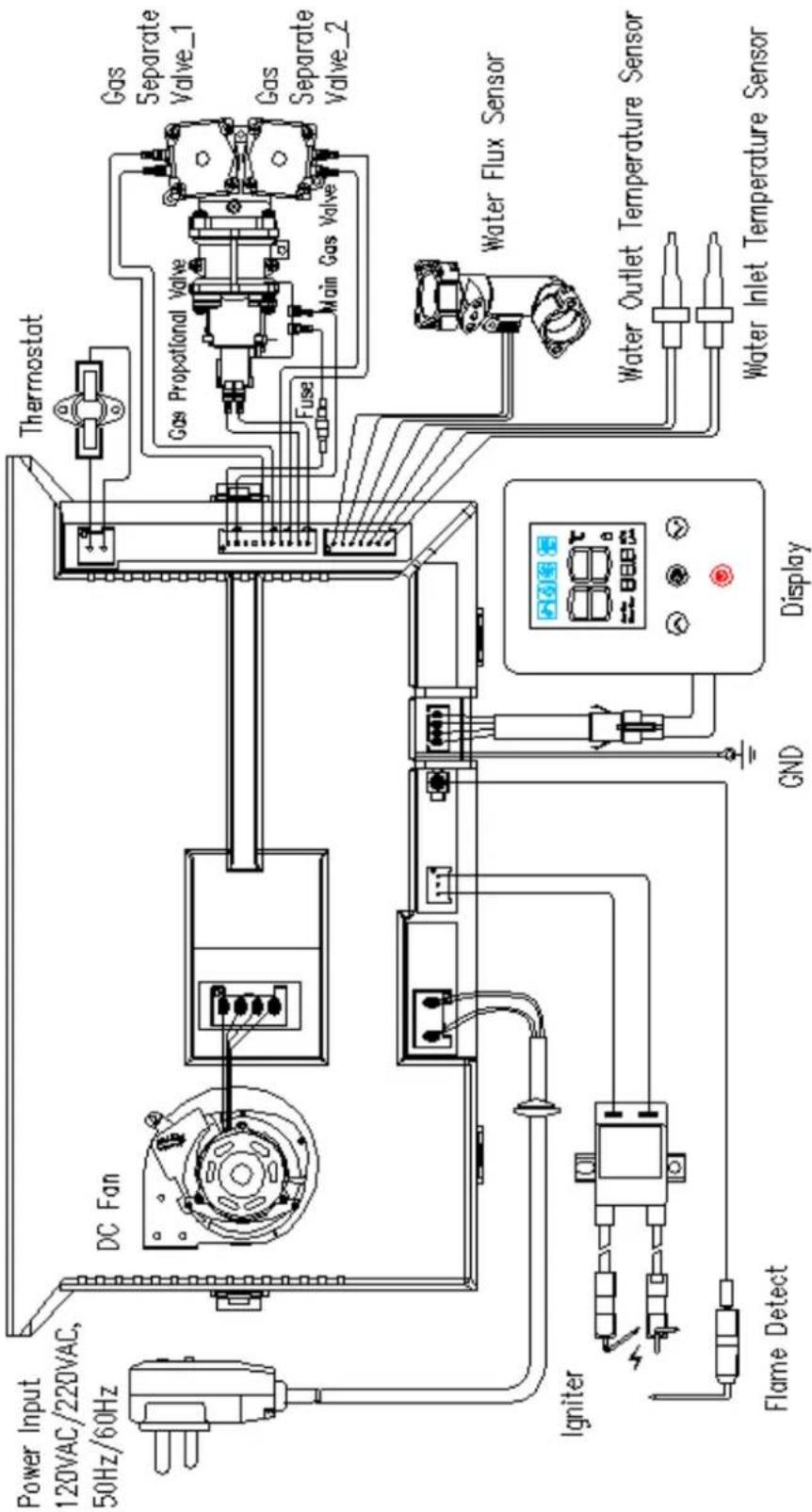
●Packaging and Accessories....23 - Electrical diagram....24
- Conversion instrucons....25
Special Advice
Read the technical instrucons before installing the appliance.
Read the user's instrucons before lighng the appliance.
The manufacturer or any danger resulted from installaon and operaons not bear responsibility for any danger resulted from installaon and operaons not in accordance to this manual.
When the outdoors temperature is less than 0^ C, the residual water inside the heater must be drained aer use.
EN26: 2015
Features & Benefits
■ Micro-Computer Intelligent Control System
The core component of the gas water heater is micro-computer intelligent control system, which is one of today's most advanced mechatronic technology. The CPU chipset can analyze automacally and set the opmal working parameter rapidly according to dierent data such as the owing water quantity, the pressure situation and the actual inlet water temperature.
■ Digital Control for Automac Constant Temperature of Outlet Water
This funcon is to monitor the outlet water temperature by a temperature sensor and to transfer the informaon to the micro-computer, so that the micro-computer could adjust the gas and air supply quantity to guarantee the constant outlet water temperature according to the temperature set by the user and the actual inlet water temperature automacally.
■ Low Start-Up Water Pressure
The lowest start-up water pressure of this product could reach 0.02MPa(the minimum water rate is 2.5L/min), so it could also be used in the residence area with low water pressure.
■ AI Arcial Intelligent Memory Funcon
The gas water heater could work with the temperature you set last me when you restart it, so that you do not need to set the temperature again, which is great experience of the idea of ergonomics.
■ Eecve and Energy-Saving
This product has advanced technologies called Strengthened Combuson and Forced Combuson. These patents aim to make the best use of heat energy with high working eciency.
■ Set Temperature by Touch
You could set the required temperature easily by touching the digital display. The seng temperature is from 35^ C to 65^ C, which can meet dierent water temperature requirements with easy operaon.
■ Mulple Safety Protecon
This product has safety protecons includes self-check protecon, ame-out protecon, over-heat protecon, accidental power-cut protecon, fan breakdown protecon, over electric load protecon, electric leakage protecon, over wind pressure protecon, over temperature protecon, ming protecon etc.
■ Connection To The Solar System
If the circuit board of water heater is with the funcon that can be in series with solar water system, water heater will be with the following condion: when seng temperature is 5^ C less than water inlet temperature, water heater will stop working showing code of EE with sound of hummer ten mes. When seng temperature is at least 5^ C more than water inlet temperature, water heater can start up automatically and work normally. When installed in series with a solar water heater, a water mixing valve must be ed at the tapping point to prevent boiling water.
Tips
The above conclusion comes from the safety protecon test under lab experimental conditions. It may be aected by the surroundings in actual using environment. Thus, please use the product in proper conditions rather than using it devastatingly.
Especificaciones
| Model | CCVEST11NOXGN | CCVEST11NOXGB | CCVEST14NOXGN | CCVEST14NOXGB | |
| Nominal heat input(Hi) | 22 kW | 22 kW | 28 kW | 28 kW | |
| Nominal heat output | 19,2 kW | 19,2 kW | 25,4 kW | 25,4 kW | |
| Minimum heat input | 8 kW | 8 kW | 9 kW | 9 kW | |
| Minimum heat output | 7,4 kW | 7,4 kW | 8,2 kW | 8,3 kW | |
| Max flow rate(rise 25°C) | 11 kg/min | 11 kg/min | 14 kg/min | 14 kg/min | |
| Appliance type | C13, C33 | ||||
| Gas type | 2H-G20mbar | 3B/P-G30-29mbar | 2H-G20m bar | 3B/P-G30-29mbar | |
| Gas category | I2@20mbar | I3B/P-30-29mbar | I2@20mbar | I3B/P-30-29mbar | |
| PIN number | 0063CR7772 | ||||
| Max water pressure | Pw~10 bar | ||||
| Min water pressure | Pw~0,2 bar | ||||
| Electrical power supply | 220-240VA,50Hz | ||||
| Electric power | 29W | 29W | 38W | 38W | |
| Degree of electrical protecon | IPX4 | ||||
| Ignion method | Water Control Automac Pules Ignion | ||||
| Pipe joint | Gas inlet | G1/2 | |||
| Cold water inlet | G1/2 | ||||
| Hot water outlet | G1/2 | ||||
| Flue duct diameter | ∅ 100 external, ∅ 60 internal | ||||
Warning:
- Read the technical instructions before installing the appliance.
Parts Name
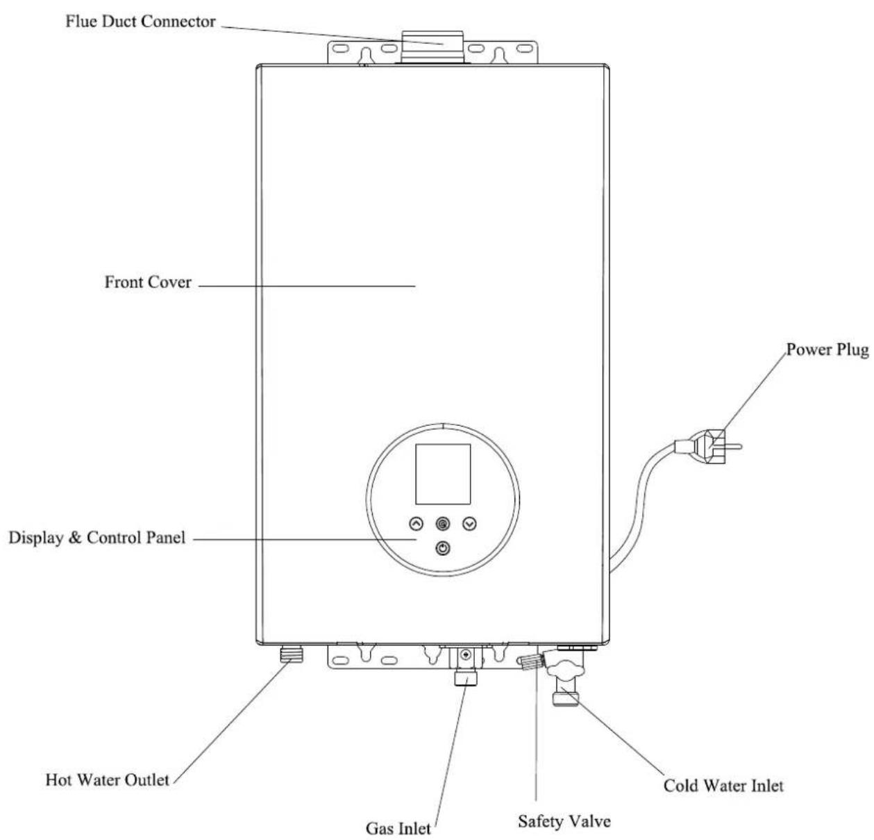
natural_image
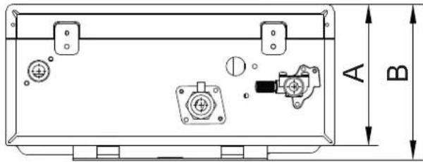
Technical diagram of a rectangular electronic device with mounting holes and internal components, labeled A and B (no text or symbols beyond labels)| Model name | A | B |
| CCVEST11NOx | 150 | 165 |
| CCVEST14NOx | 170 | 185 |
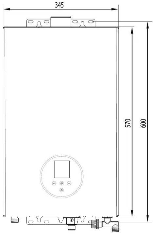
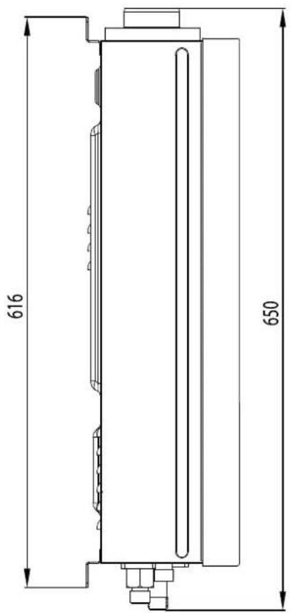
Fig. 2(Unit: mm)
(The dimension information is for reference only. Please refer to the actual product.)
Installation
Contact your local gas dealers or gas management department for a qualified engineer to install the gas water heater (users are recommended not to install by themselves). The installer should be called on to install and adjust the appliance, where appropriate.
This product is prohibited to use this gas water heater when ue pipe has not been installed correctly according to instrucons.
■ Installaon Requirements
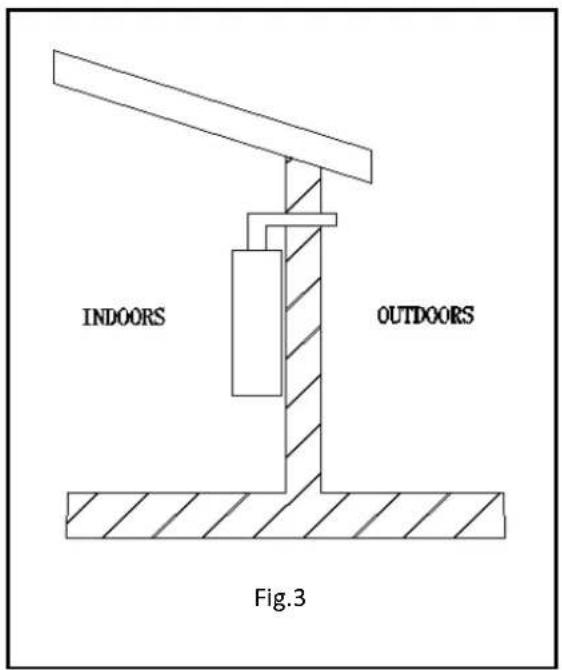
- The use of the gas water heater should be installed through an external wall, the heater cannot be installed in outdoors. (Fig.3)
natural_image
Illustration of a hand washing a bottle with a pipe, showing chemical symbols (no text or labels)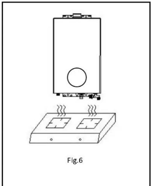
natural_image
Technical line drawing of a device with heating elements and a base plate, labeled Fig.6 (no text or symbols on the diagram itself)- The gas water heater installed in a suitably venled room, in accordance with the regulaons in force.. It is not allowed to install in the bedroom, underground, bathroom or any other places with poor ventilaon.(For B23, B53 type)
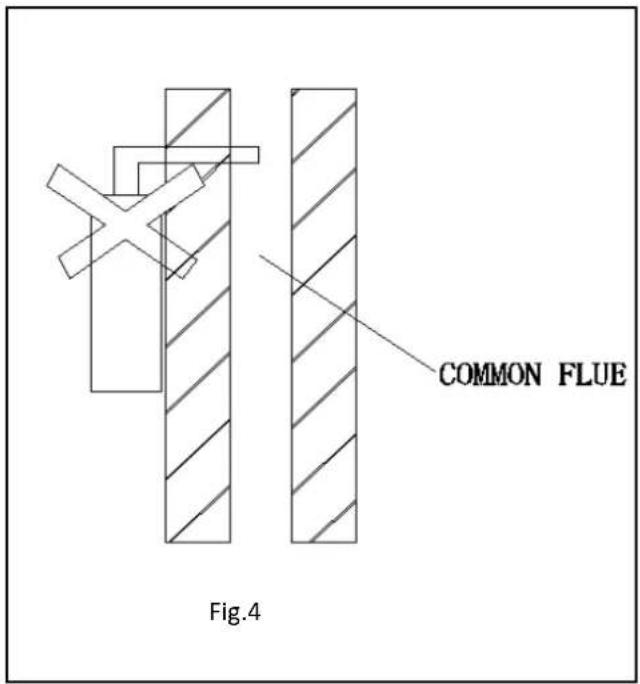
- The ue of the heater cannot be connected to a common ue (Fig. 4).
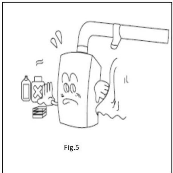
- Please don't install the heater in places where special chemicals are used, such as the laundries or factories etc., otherwise it may cause rusng, shorten the lifeme of the heater, or prevent normal working.(Fig. 5)
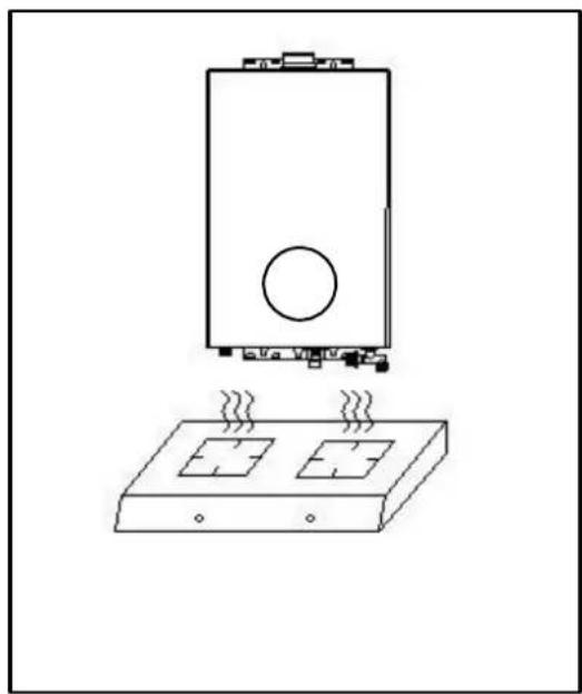
- Don't install the heater above the gas stoves or other heat sources. (Fig. 6)
- The gas water heater should be kept away from the combustible materials with the distance shown in Fig. 7 at least.
- When the installaon parts' materials are combustible or ammable should be used frame-proof board to isolate, heat-resistant plate and wall gap should be greater than 10mm, and the size of heat plate should be larger than water heater shell for 10mm. (Fig. 8)
Combustible Materials
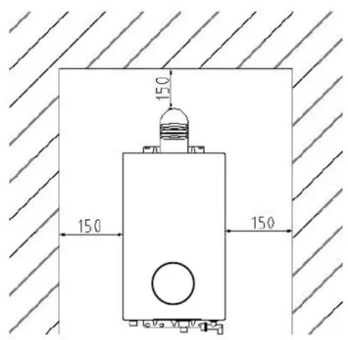
Fig. 7
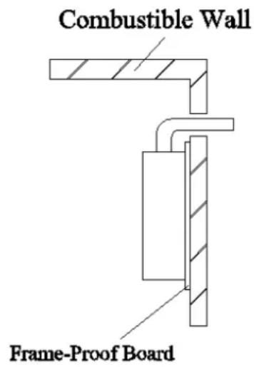
Fig. 8
- The electric wires and electric equipment are not allowed to be placed on the top of the gas water heater. The horizontal distance between the gas water heater and other electric equipment should be more than 400mm.
- The power socket must have a reliable ground wire to improve safety. In order to reduce the number of mes of plugging, it is beer to use a socket with a switch. Whenever the water heater nishes working, please switch it to avoid being electried in a long term. The power supply socket should not be installed in the moist environment.
- The socket should be installed at the side of the product, and never be installed below the machine or the place with splashes, near the heat source, in exposure to sun and rain, or the place where it is not easy to control.
- The installaon place of socket must be far away from the spraying space, so as to avoid
spraying the socket during shower.
■ Installaon Method
- Installaon of Gas Water Heater
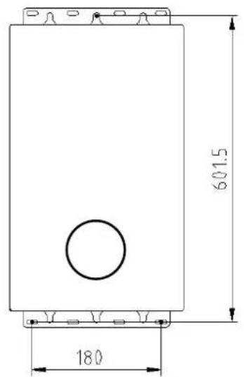
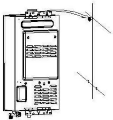
Drill holes in the wall according to Fig.9, put an expansion bolt into the upper hole and plasc gasket into the lower hole, mount the water heater vercally on the upper bolt without inclinaon and ghten the lower holes with expansion bolts.
natural_image
Technical line drawing of an electrical enclosure with wiring and mounting points (no text or symbols)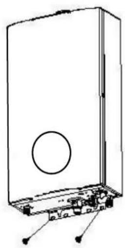
natural_image
Technical line drawing of a device casing with internal components and mounting base (no text or symbols)Fig. 9 (Unit:mm)
- Installaon of water and gas pipes (Fig. 10)
- It can be used when the ue system can ensure that the provided gas pressure can reach the lowest requirement. If gas water heater reaches the rated heat input, the gas pressure must reach the rated heat input in the technologic parameter form.
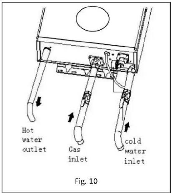
- Gas inlet
(1) Before connecng the gas supply, check the rang plate on the right side of the right front cover to be sure that the heater is rated for the same gas to which it will be connected.
(2) All such pipe shall be either new or previously used for no other purpose than conveying gas; and must be in good condition and free from internal obstrucons. Burred ends shall be reamed to the full bore of the pipe. All ngs used shall be of malleable iron, yellow brass, or approved plasc ngs. And exible tube is not allowed.
(3) When your conncons are made, check for gas leaks at all joints (this includes all existing piping). Apply soapy water to all gas tngs and gas valve. Soap bubbles are a sign of a leak.
NOTE: No substance other than air, carbon dioxide or nitrogen can be introduced into the gas piping.
NOTE: If you have a leak, shut o the gas. Aer verifying the leak, ghten appropriate ings to stop leak. Turn the gas on and check again with a soapy soluon. Never test for gas leaks using a match or ame.
- Cold water inlet
(1) When facing the heater, the cold water inlet is on your right and the hot water outlet is on your le. Although water piping throughout your structure may be other than copper, we recommend that copper piping be used for at least 0.92 m before and aer the heater (follow local codes). Keep water inlet pipe to no less than 1/2" diameter to allow the full ow capacity.
(2) Remember that water pressure must be sucient to acvate the heater when drawing hot water from the top oor. If the hot and cold connexons to the heater are reversed, the heater will not funcon. 1/2" Copper or brass ngs work best when connected to the connectors. The exible type connectors will make insllaon easier and seals to the water valve by means of a union connexon with a washer type gasket at the joint. No pipe dope or thread tape is to be used at this joint. Be certain there are no loose parcles or dirt in the piping. (Fig. 10)
(3) Water pressure must be sucient to acvate the water heater, the maximum pressure for the appliance is 10bar, even with the eects of water dilaon, the water pressure in the appliance shall not exceed this value.
- Hot water outlet
Use a exible or rigid pipe to connect with the sprayer without valve. If a valve or switch is connected to the sprayer, the outlet pipe shall not use heat and pressure unendurable material such as plascs, aluminum pipes, so as to avoid the pipe from breaking and scalding the user.
3. Installaon of the ue:
- Flue Duct Installaon of Forced-Exhausted Gas Water Heater(B23, B53type)
This product is forced exhaust type gas water heater; it can be used only aer the ue duct is installed according to the requirements strictly and can exhaust the waste gas to the outdoor area. It's not allowed to use the gas water heater without installing the ue duct correctly.
Please follow the below requirements during the installaon of ue duct:
(1) Please use the ue supplied by our company, referring to Fig. 11 about the installaon method. If the ue duct is too short, you can extend it aptly. Check the ue duct and see if there is any damage or leakage every half a year.
(2) The length of the ue duct should be less than 8m,
(3) The horizontal distance of the ue duct is the shorter the beer. The ue duct end should have a 2^0 downward inclinaon (Fig. 11), so as to let the condensing water ows out.
(4) The distance between the ue duct and the combustible materials should be more than 150mm. If the ue duct needs to get through the combustible materials or wall, it should use the heat shield material to pack the ue duct with the thickness over 20mm. (Refer to Fig.7)
(5) No cement between the ue duct and wall for the convenience of maintenance.
(6) The ue duct should be xed ghtly. The conncon part could use self-adhesive foil to avoid the waste gas going back into the room.
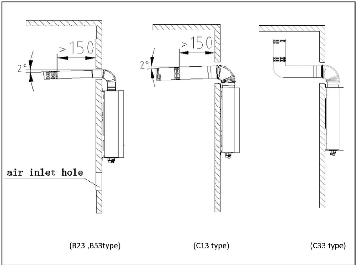
Fig. 11
- Flue Duct Installaon of Forced Exhaust & Air-Supply Type Gas Water Heater(C13,C33 type)
This product is a Forced Exhaust & Air-Supply Type gas water heater, it can be used before exhausng the waste gas to the outdoor according to the strictest requirements. It's not allowed to use the gas water heater without operang the ue correctly.
Please follow the below requirements during the installaon of ue duct:
(1) Please use the ue supplied by our company, referring to Fig. 11 about the installaon method. If the ue duct is too short, you can extend it aptly. Check the ue duct and see if there is any damage or leakage every half a year. Install the ue aer the heater body is xed. First, put the xed ue through the hole in the wall, then insert the elbow into the exhaust outlet of the heater smoothly, the ue end should have a 2^ downward inclinaon (Fig. 11), otherwise the rain may ow into the heater and damage it.
(2) The length of the ue duct should be less than 4m, and the number of elbows should not be more than 4 (one elbow equivalent 1m straight pipe).
(3) The distance between the ue duct and the combustible materials should be more than 150mm. If the ue duct needs to get through the combustible materials or wall, it should use the heat shield material to pack the ue duct with the thickness over 20mm. (Refer to Fig.7)
(4) No cement between the ue duct and wall for the convenience of maintenance.
(5) The ue duct should be xed ghtly. The conncon part could use self-adhesive foil to avoid the waste gas going back into the room.
Cauons for ue installaon
- Please use the ue supplied by our company, Other ues with dierent specicaons are strictly prohibited. Do not change the specicaon of the ue.
- The installaon of the ue must be correct, otherwise the waste gases will ow back and be
dangerous.(Fig. 12)
| w rong installation | problem caused | correct installation |
| exhaust gas leak into room | ||
| abnormal combustion | ||
| work abnormal ally |
Fig. 12
Using Methods
- Display content instrucon
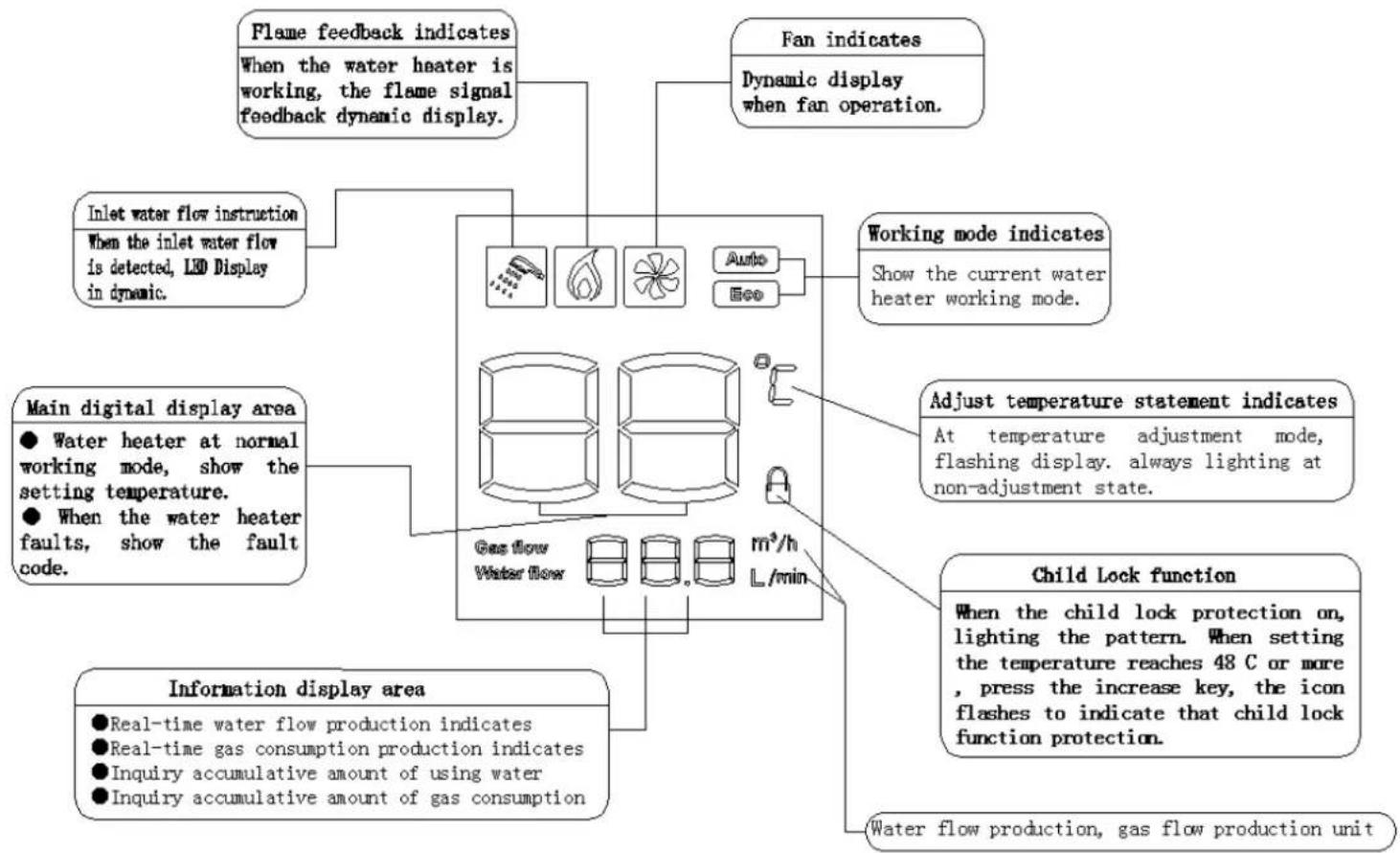
flowchart
graph TD
    A["Main digital display area"] --> B["Main digital display instruction"]
    B --> C["Flame feedback indicates when the water heater is working, the flame signal feedback dynamic display."]
    A --> D["Information display area"]
    D --> E["Real-time water flow production indicates"]
    D --> F["Real-time gas consumption production indicates"]
    D --> G["Inquiry accumulative amount of using water"]
    D --> H["Inquiry accumulative amount of gas consumption"]
    A --> I["Gas flow Water flow"]
    I --> J["m³/h L/min"]
    J --> K["Working mode indicates Show the current water heater working mode."]
    K --> L["Fan indicates Dynamic display when fan operation."]
    A --> M["Adjust temperature statement indicates At temperature adjustment mode, flashing display. always lighting at non-adjustment state."]
    M --> N["Child Lock function When the child lock protection on, lighting the pattern. When setting the temperature reaches 48 C or more, press the increase key, the icon flashes to indicate that child lock function protection."]
    A --> O["Water flow production, gas flow production unit"]
- Touch buon instructions (the posion of the touch button may change according to dierent model, but the buon funcon is the same)
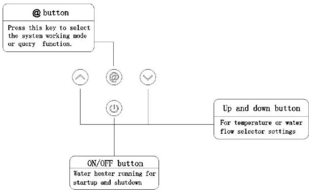
flowchart
graph TD
    A["@ button"] --> B["Press this key to select the system working mode or query function."]
    B --> C["ON/OFF button\nWater heater running for startup and shutdown"]
    C --> D["Up and down button\nFor temperature or water flow selector settings"]
    C --> E["@ @ ✓"]
    C --> F(@ ✓)
2. Preparaon before ignition
- Make sure that the gas used is in accordance with the gas spulated in the label.
- Insert the plug, and then switch on the power. (The buzzer sounds "bi")
- Turn on the gas valve.
3. Temperature Seng
- Press the “ ⏻” (on/o) key on the control panel, the screen display and the designed hot water temperature. Press Up “ ⏻” or Down “ ⏻” to set the hot water temperature as desired. The lowest hot water temperature of this product is 35°C, highest is 65°C. 35 \~ 48 °C each me you press the buon to change 1 °C, 48\~65°C each me you press the buon to change 5 °C (that is 48°C、50°C、55°C、60°C、65°C), Each me you press the buzzer sounds.
4. Ignion & Water Outlet
- Open the water valve, there will be spraying signal shown on the screen. When the fan whirls, the igniter turns on and ame shows, hot water will come out accordingly. The display shows the seng temperature of outlet water.
- When using, water outlet ow and temperature can be adjusted in the same method as menoned. Aer opening water and starng, Seng the range of 35-48 °C, Above 48 °C, only press down key (Child lock funcon to prevent burns). If want to set the temperature higher than 48 °C, turn o the hot water faucet and then press the buon to warming.
- When the water valve is open, but the switch stays at OFF posion, the water heater will stop working, and only cold water runs out. If hot water is needed, you should press ON buon.
- Turn o the water valve and water heater stops working, but the fan sll blows the combuston chamber for several seconds. The machine will show the temperature set last me when opening the water valve next me.
- Every me aer using the gas water heater, the gas valve must be closed, and AC power must be cut.
Aenon:
▲ If the water valve is open before the water heater is switched on, the gas water heater will into the protective mode, and the buzzer sounds. Please close the water valve then.
▲ It might take several trial ignions aer installaon or the rst use aer recharging the gas tank to push out all the air remained in the gas pipe.
▲ The temperature shown on the screen is the seng temperature, while the outlet water temperature diers according to the length of pipes and dierent seasons. Therefore, please refer to the actual outlet water temperature.
▲ If hot water ow excesses the water heater's capacity, the water may not be hot enough. Please turn down the water ow accordingly
▲ Every me the water heater starts working, please pay aenon to the setng temperature on the display and be careful not to being scaled.
▲In order to avoid being scaled, whenever using the water heater, you must test the water temperature with your hand before showing.
▲ When the gas water stops working and the display shows error codes, please close the water valve and reopen. Or press the on/o buon unl the machine is o, and then restart it. If the water heater sll cannot operate regularly, please turn off the gas valve and cut the power, recharge the machine and ignite again aer a few minutes.
5. Use funcon mode
In standby mode (ie, no water status), press the funcon (@) key, you can select "Auto", "Eco", "normal" three modes in turns, they can cycle, the system default normal mode.
Three types of funcon mode instrucon
- Normal mode(default): According to the user to set automac temperature thermostat, then "Auto", "Eco" display lights are not bright.
- Auto mode: ("Auto" display lights is bright.) According to the inlet water temperature, the system automacally adjusts the seng temperature (as shown in Table 1), allowing users to get the most comfortable hot water supply in anyme.
Table 1 Temperature mapping table
| No. | Local Water Temperature | Corresponding Temperature |
| 1 ≤ | 15°C | 45°C |
| 2 | 16°C 21°C | 43°C |
| 3 | 22°C 27°C | 40°C |
| 4 ≥ | 28°C | 38°C |
Note: Under the Auto mode, aer the heater switch on, the temperature displayed is the one set before the heater starts to work. The temperature will not change according to the local water temperature change aer the heater starts to work.
- Eco mode: ("Eco" display lights is bright.) In the state of saving mode, aer calculation by microcomputer, automacally adjust the amount of gas supply, compared other modes more economical by water heater gas consumption, not only save gas, but also can guarantee a constant water temperature to meet the requirements of users.
In the state of saving mode, the user can freely select the desired of seng water temperature, the user presses the up or down keys to adjust the seng temperature does not exit the power saving mode, in this case the user needs in the standby mode press the funcon key again to exit the power saving mode.
- Instant hot water producon and real me air consumpon display
When the water heater in working condion, the display will take turns showing the current real me hot water producon and real me gas consumpon, the gures will be changed accord the actual working condions, so that users can understand the water heater current working condions.
For example: When the real time informaon display "12.0L / min", indicates that current real me hot water producon by water heater per minute 12L. When the real me informaon display "2.0m³/h", indicates that current real me gas consumpon by water heater per hour 2.0m³
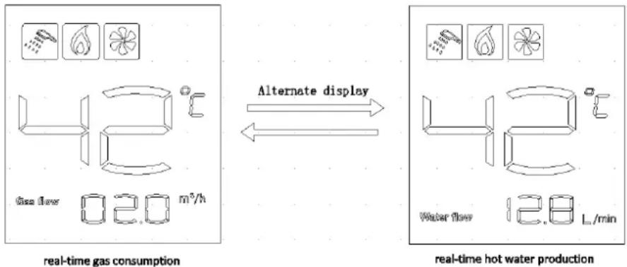
flowchart
graph LR
    A["Gas flow: 0.20 m³/h"] --> B{Alternate display}
    B <--> C["Water flow: 12.8 L/min"]
Fig.13
- Inquiry the cumulative amount of gas and water
In working statement, @ buons can inquire about the cumulative water consumption and gas consumpon. Click the @ key to query cumulave amount of using water informaon, press @ key again can be inquired accumulated gas consumpon informaon. Press the third me for the @ buon or no operaon for 20s, can exit the inquiry funcon.
Note:
●Real-me air consumpon show the basic unit of m^3/h
●Real-me hot water producon show the basic unit of L/min
- Cumulave amount of using water and gas consumption show the basic unit of m^3 , When the display numbers reach 999m^3 , water record is automatically cleared. For example, when the query informaon display "Water producon 180m^3 ", represents a total cumulative amount of water heater 180m^3 . When real-me informaon shows "volume 8.3m^3 ", it indicates the water heater cumulative total air consumption 8.3m^3 .
- Cumulave gas consumption and cumulative amount of water is automatically cleared aer power failure
- The contents of the query funcon display only for reference, can not be used for measurement.
Safety Cautions
■ Prevenon of freezing water
Drain the residual water inside the heater to prevent freezing water aer every use when the environment temperature is near or under 0^ C, do as instructed (Fig.14)
- Close down the gas valve ①
- Turn the water temperature knob ② to "low" posion, or turn the water volume buon knob to "large" posion (level).
- Close down the cold water valve sans③, if a valve is installed on the hot water circuit, open it.
- If there is a control valve④ at the hot water outlet, please open it.
- Turn the drain valve⑤ and take off, replace it aer the residual water is completely discharged.
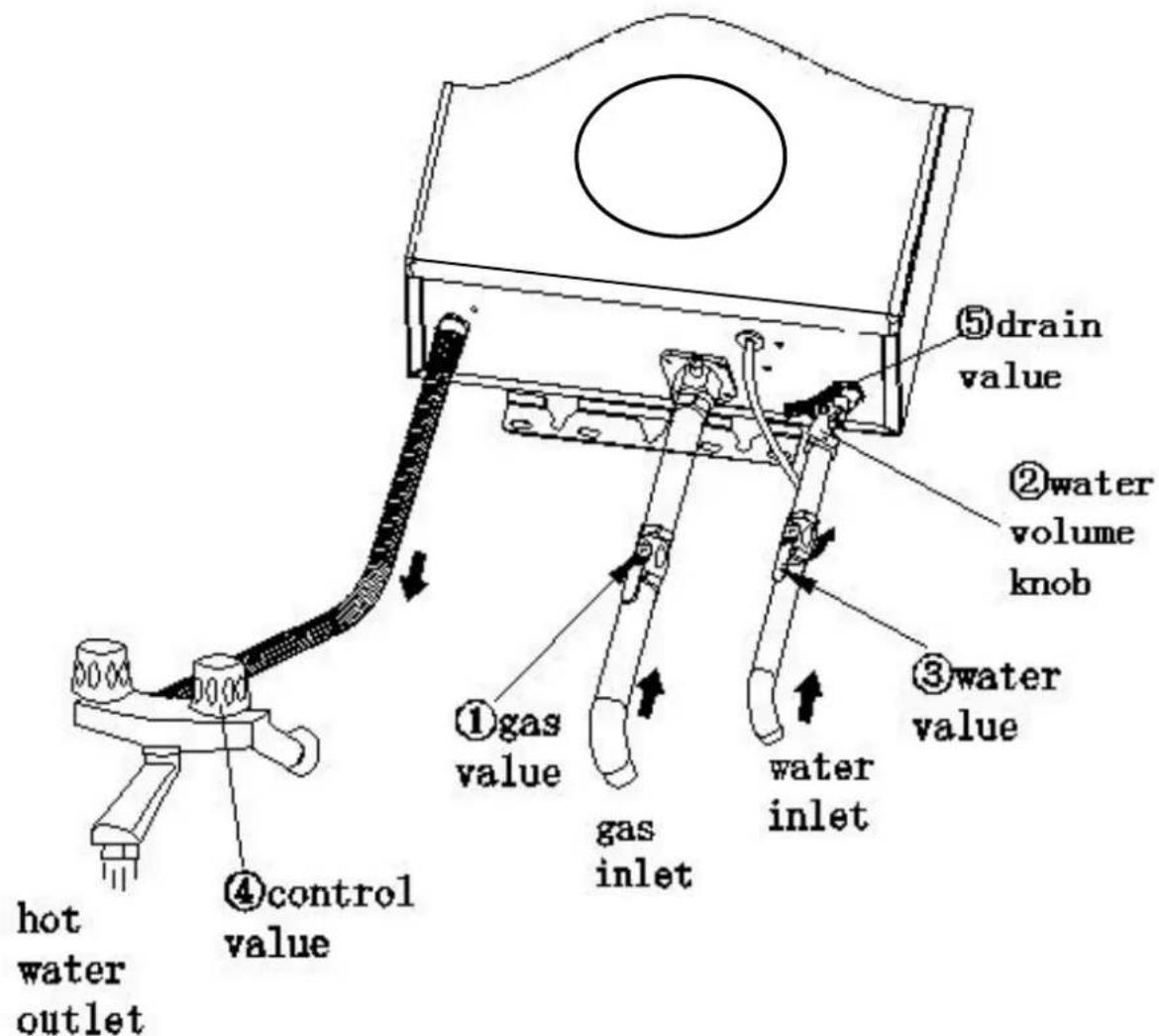
Fig.14
■Gas accident prevenon
- Check if the ame of burner is out aer use and do not forget to turn o the gas valve (Fig. 15) and power.
● Always check the gas connectors for gas leakage with soapsuds. If any gas leakage is detected, open the room windows and doors. At that moment, do not ignite or operate the switch of electric appliances or plugs because the ame or electric spark can result in explosive accidents. (Fig. 16)
- Heaters must use the gas type which the heater is designed to use, dierent type of gas or the same gas in dierent place must not be used.
● Always check the gas pipe and change the pipe every year to avoid gas leakage due to cracking.
- If the ame goes unsteadily, stop using the water heater and contact the qualified service facility for repair or adjustment.
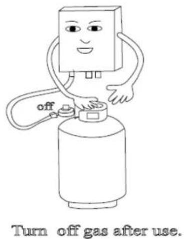
Fig. 15
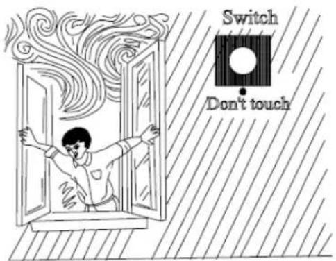
Open the window in case smelling
Fig.16
■Fire prevenon
- Do not leave the water heater unaended whilst sll in operaon.
- In case of power failure or water failure, turn o the gas valve and water inlet valve.
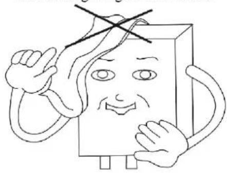
- Do not place towels or clothes on top of the water heater.(Fig. 17)
- Do not store inammables, explosives or volales near the water heater. (Fig. 18)
- Never incline the gas tank or turn it upside down, the uid gas is easy to ow into the heater and cause res.
Do not hang thing on or overhead
natural_image
Cartoon character with a smiling face and raised index finger, wearing a hooded top (no text or symbols)Fig.17
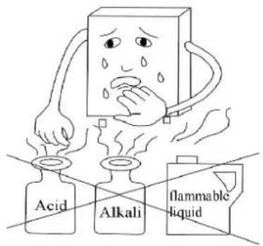
Fig.18
■ Carbon Monoxide toxicosis prevenon
- This product must exhaust the waste gas to the outdoor area during working, so the ue duct must be connected to the joint on the top of the water heater to exhaust the waste gas out to the outdoor area, keep the air fresh indoor and avoid incomplete combustor. Otherwise, it will cause danger or even death.
- Too low or too high gas pressure leads to abnormal combustor. At that moment, stop using the water heater and get in contact with a service engineer.
- Dust and accelerated carbon would block the heat exchanger due to long me use, and aect the combuston performance, causing the Carbon monoxide to increase. Therefore, contact a qualified person to clean and clear the dust and accelerated carbon every half year to ensure the combuston product discharges smoothly.
- The heater must be installed vertically, if inclined it will make the ame touch the heat exchanger and cause the monoxide to increase.
■Don't drink the heater water
The water in the heater is not suitable for drinking.
- Handle with abnormal conditions
If there is abnormal burning (ame light-back, ame li, yellow p or black smoke, etc), smell or noise, or other emergent situaons, keep calm and shut o the gas supply valve and power switch, and contact the service facility or gas dealers for repair or adjustment.
■Scald prevenon
- When using the heater disconnuously, be careful not to be scalded by the over high temperature hot water at the start and stop mes.
- During use and immediately aer, do not touch any places especially the surround of the ame Check window or the front cover except for the knob and control panel in order to avoid scalding.

WARNING: Forbid any interference with a sealed component, a fire or explosion may result causing property damage, personal injury or loss of life.
Maintenance
▲ The appliances should be checked and maintained periodically by a competent person
▲Check the gas tube/pipe regularly for any defect. Contact service center for any doubt. Always check the gas pipe for cracks.
▲ Always check for leaking water.
▲ Ask qualified technicians to examine the burner, ue and fan once a year.
▲ Always check the ame inside the water heater for any abnormal condions.
▲ Keep the cover of the water heater clean.
▲ This product uses water pressure to open the channels. When the water pressure is lower than 0.2bar, the heater cannot be ignited.
▲ The drain valve is dripping. When the water pressure is too high, the drain valve will release the water so as to reduce the pressure to protect the heater.
When the heater is supplying hot water to several points at the same me, the hot water ow would be reduced, or no hot water will issue at all.
▲ When the temperature outside is too low and the exhausted gas meets the cold air, it will be condense as white fog. This is normal.
When the water temperature is too high, set to a lower temperature and reduce the water tap. If the water temperature outlet is too high, please open the tap to reduce the temperature.
When the water temperature is too low, and the hot water volume is so high so that it exceeds the heater's heang power, the outlet water will be not hot enough, please reduce the water volume.
▲ In order to ignite immediately, the fan in the appliance will delay running for a long time and then stop automacally. This is normal.
When you use the mul-funcon shower, the resistance may be too large, and the water inlet pressure will be too low or the water inlet volume will be too little (below the starng-up water volume), theremay be amout or can not be ignited, please choose the suitable shower funcon.
▲ The residual water in the heater may be frozen in the winter, this is bad for the heater, so you must drain the water aer use. (Please refer to the drain methods.).
▲ In order not to create scaling, please close the gas valve aer using the heater, let the hot water out of the appliance. When the outlet of the hot water is cold, close the cold water valve.
Cleaning: The water heater should be cleaned annually, keep the dust away from ue gas passageway. See the Cleaning Instrucons below.(Only for service engineer)
1). Turn o power, shuto gas supply;
2). Wait one hour to cool down water heater;
3). Remove the front cover, by taking out Cover Screw;
4). Using compressed air or equivalent to clean the area between the ns and the heat exchanger;
5). Do not unscrew or move any other parts of water heater;
6). Aer Cleaning, put the front cover back.
Trouble-Shooting Guidance
| Causes\Errors | Flame out while using | Non-ignion aer opening the cold water valve | Deagraon aer ignion | Yellow ame with smoke | Abnormal ame with strange smell | Ignion with strange sounds | Water sll not hot,when turning to the high temperature posion | Water too hot, when turning to the low temperature posion | Flame out when turning to the low temperature posion | Flame not out when the cold water valve is closed | Soluons | |
| Main gas valve o ● | Turn on the main gas valve widely or change new gas. | |||||||||||
| Main gas valve half on | ● | ● | Turn on the main gas valve widely | |||||||||
| There is air in the gas pipe | ● | Constantly connue to turn on the water supply control valve | ||||||||||
| Supply gas pressure inappropriate | High | ● | ● | Contact the technician to check the gas source pressure adjustment valve | ||||||||
| Low | ● | ● | ||||||||||
| Main cold water valve off | ● | Turn on the water supply main valve | ||||||||||
| Frozen | ● | Reuse it until melng | ||||||||||
| Pressure of cold water too low | ● | ● | ● | Contact the technicians to check water pressure | ||||||||
| Adjust water temperature wrongly | ● | ● | Rotate the water ow adjustment rod appropriately | |||||||||
| Air supply not enough | ● | ● | Improve air exchange, and let more fresh air in | |||||||||
| External wind pressure too high | ● | ● | ● | Stop using it | ||||||||
| Burner assembly blocked | ● | ● | ● | Contact aer-sales services | ||||||||
| Heat exchanger assembly blocked | ● | ● | ● | The same as menoned above | ||||||||
| Errors in the water control device | ● | ● | ● | ● | ● | The same as menoned above | ||||||
Enclose: Explanaon of the Error Codes
In the process of using, the display of the re, wind and other paerns disappeared, because the security device has been caused by acon. Display ashing fault code shows that the failure of its occurrence, the reason for the excepon.
Fault code has been ashing when failure. On such occasions, please turn o the hot water value and then open, or close / open the monitor, and then operate 1-2 mes. If the display sll show the fault code, please be sure to close the water valve and valve, unplug the power plug, and contact the aer-sales service.
| Error Code Explanaon | |
| 01 Inlet water temperature sensor breaks down | |
| 10 Detect a ame signal through pre-check | |
| 11 Ignion fails | |
| 12 Normal combuston ames out accidentally | |
| 13 Thermostat fault protecon | |
| 32 Fan blocking protecon | |
| 40 Fan or its drive circuit breaks down | |
| 50 | Over high temperature protecon (outlet) |
| 51 | Over high temperature protecon (inlet) |
| 60 Outlet water temperature sensor fault protecon | |
Packaging and Accessories
| Descripon Quanty | |
| Gas water heater 1 pc | |
| Connector of gas inlet (with rubber seal ring) 1 pc | |
| Expansion screws 1 set | |
| Mounng screws 2 pcs | |
| User manual | 1 pc |
| Self-tapping screws | 2 pcs |
| Flue duct (B23 type) | 1 set |
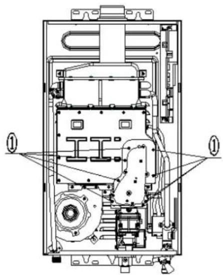
※If change, No special advice!
Conversion instructions
pic 1
natural_image
Technical line drawing of an internal electronic device with labeled components (no text or symbols present)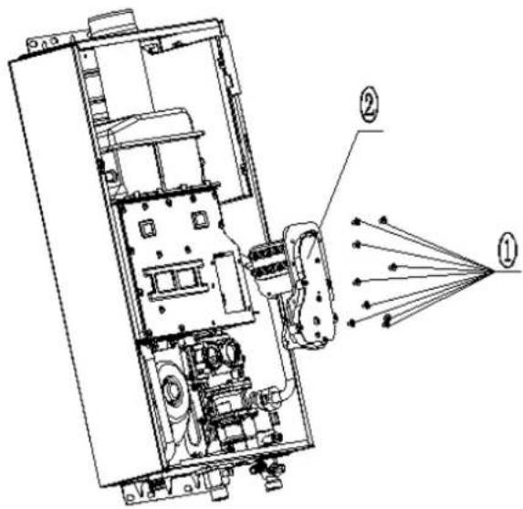
pic 2
natural_image
Technical line drawing of an internal mechanical or electrical device with no visible text or symbols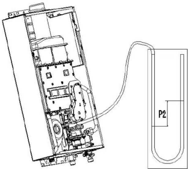
10-12L
pic 1
natural_image
Technical line drawing of a mechanical device interior with no visible text or symbols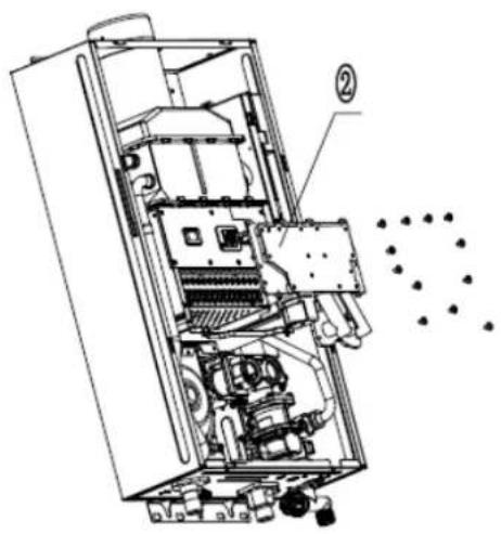
natural_image
Technical line drawing of an internal appliance or enclosure with visible internal components and a dotted pattern (no text or symbols)pic 2
natural_image
Technical line drawing of an internal combustion chamber with labeled components (no text or symbols present)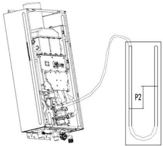
natural_image
Technical line drawing of an internal electronic device with a cable and labeled component P2 (no text or symbols beyond labels)14-17L
Technical instrucon
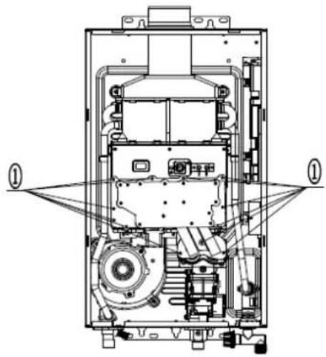
| Step 1Open front cover | 1.Screw o the front panel and disconnect the display and control unit terminal. |
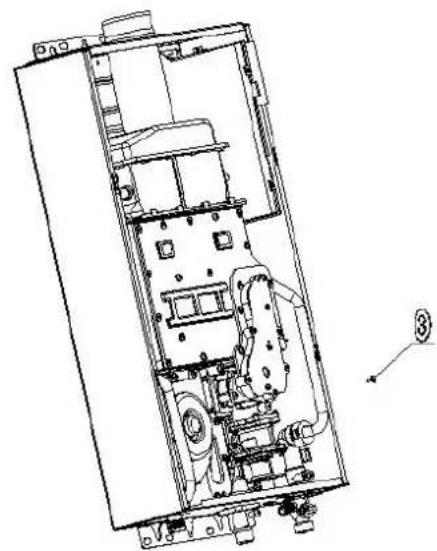
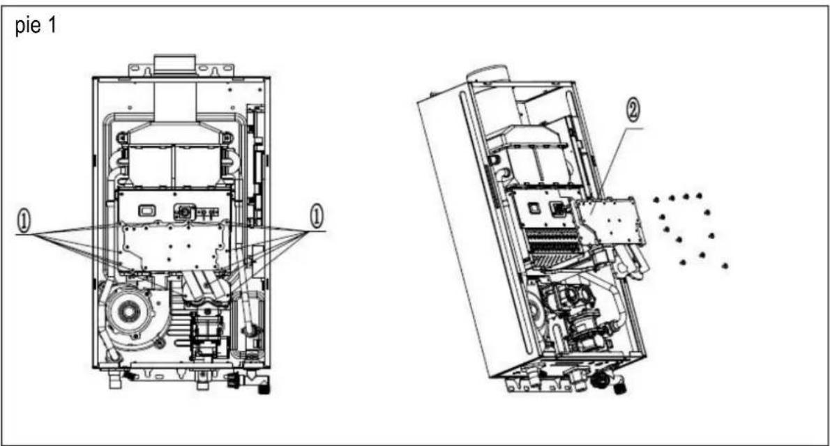
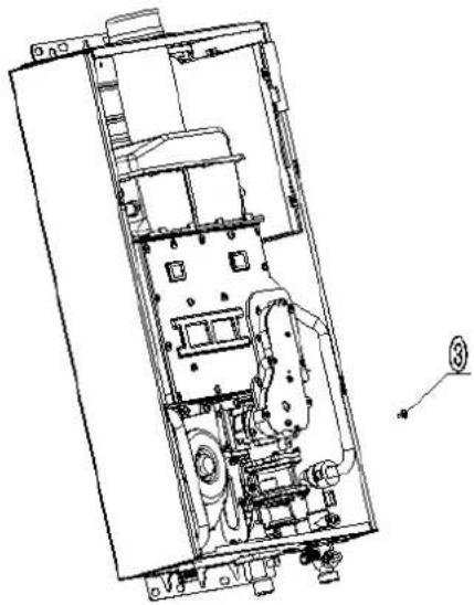
| Step 2Replace gas tube assembly(pic 1)Step 3Seng the gas type, volume, and model | 1.Screw o the gas tube assembly ^1 and take it out ^2 .2.Change to the matched gas ejector tube assembly.Note: It's necessary to examine the air ghtness aer change, to check the seal ring on the gas control system installed well to prevent gas leakage.1. Connect display and control unit2. Volume selecon: Within 10s, aer the system is powered on but switched o, press Up and Down keys together for 2s. Aer the buzzer rings once, "L" blinks on the display, which means that you have entered the volume selecon mode. Press On/O key to enable the adjustment funcon, and then Up or Down key to adjust the volume. Table 1 shows the volume parameter sengs.3. Gas type selecon: Aer the gas volume is adjusted, press On/O key to both conrm the modicaon and enter the next selecon interface. The "q" that blinks on the display means that you have entered the gas type selecon mode. Press On/O key to enable the selecon funcon, and then Up or Down key to select a gas type. The originally selected type is displayed the rst me you press Up or Down key, which is 12T by default. Table 2 shows the gas type parameter sengs.4. Model selecon: Aer gas type is selected, press On/O key to both conrm the selecon and enter the next selecon interface. The "F" that blinks on the display means that you have entered the model selecon mode. (It's the factory default and no need to select, just press on-o key to skip this step.) |
| Step 4Secondary pressure adjustment | 1. Aer adjusng the volume and gas type, screw o the secondary pressure screw on the gas control system3. And connect the secondary port and U type barometer with rubber pipe.2. Aer the system is switched on and it combusts normally, press Up and Down keys together for 5s. The "88" digital tube displays "26", which means that you have entered the secondary pressure adjustment mode.3. Then press On/O key. The high-order posion of the "88" digital tube blinks, which means that you can now regulate the secondary pressure of the big endian by the Up or Down key.4. Press On/O key, the low-order posion of the "88" digital tube blinks, which means that you can now adjust the secondary pressure of the lile endian by the Up or Down key.5. Aer the adjustment, press On/O key to conrm and exit from the adjustment mode.6. Aer the secondary pressure test compliant, mount the secondary pressure screw and conduct leakage test with re.Note: Aer you modify the secondary pressure, wait for 2s or 3s to ensure that the system has recorded the updated the current value. You must verify the upper limit and then the lower limit before you exit. Table 3 shows the secondary pressure of dierent gas type and volume. |
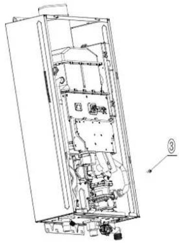
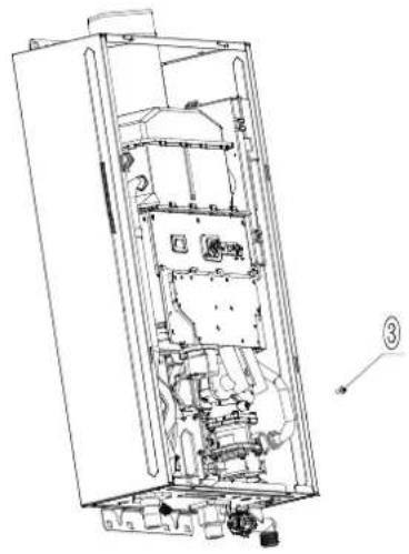
| Step 4Assemble front cover | 1. Check the airproof of nished product ensure no gas leakage.2. Assemble front cover ,ghten screws of front cover. |
| Note | 1. When replace with new gas tube assembly, noce whether the seal ring on gas control system assembly is xed well.2. Check the airproof of nished product ensure no gas leakage.3. Aer nish replacing the conversion kits, replace the corresponding labels on the appliance, for example, data plate.4. This instrucon is for reference only, take the material object as the standard. |
Replaced Part list
| Replaced Part name | diagram | Gas type | Figure No. | Specification |
| Gas tube assembly | 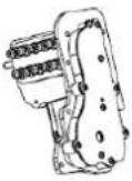 | G20 | JSQ13ST25_06B1 | hole of Φ 0.86hole of Φ 1.52 |
| G30G31 | JSQ13ST25_06B2 | hole of Φ 0.74hole of Φ 1.01 |
10-12L
Replaced Part list
| Replaced Part name | diagram | Volume | Gas type | Figure No. | Specification | NOTE |
| nozzle | 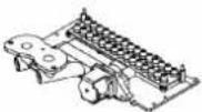 | 16L/17L | G20 | JSQ16L7_06_01B2 | hole of Φ 0.74hole of Φ 1.28 | The nozzle size is the same in the same row.The row line is the smaller size nozzle; the upper row is the larger side nozzle. |
| G30G31 | JSQ16L7_06_01B3 | hole of Φ 0.62hole of Φ 0.88 | ||||
| 14L | G20 | JSQ16L7_06_01B4 | hole of Φ 0.67hole of Φ 1.19 | |||
| G30G31 | JSQ16L7_06_01B5 | hole of Φ 0.56hole of Φ 0.80 |
14-17L
Table 2.1 Volume parameter settings
| No. | Displayed Symbol | Parameter | Parameter Description |
| 1 | L | 10 | 10L |
| 2 | 11 | 11L | |
| 3 | 12 | 12L | |
| 1 | 14 | 14L | |
| 2 | 16 | 16L | |
| 3 | 17 | 17L |
Table 2.2 Gas type parameter settings
| No. | Displayed Symbol | Parameter | Parameter Description |
| 1 | q | 12 | G20 |
| 2 | 22 | G30 | |
| 3 | 19 | G31 |
Table 3 the secondary pressure
| Liter | Gas type | P2 | |
| Max Min | |||
| 10L | G20 | 1050 ± 20Pa 300 ± 10Pa | |
| G30 1050 ± 20Pa 300 ± 10Pa | |||
| G31 1310 ± 20Pa 300 ± 10Pa | |||
| 11L | G20 1210 ± 20Pa 300 ± 10Pa | ||
| G30 1260 ± 20Pa 300 ± 10Pa | |||
| G31 1590 ± 20Pa 300 ± 10Pa | |||
| 12L | G20 1430 ± 20Pa 300 ± 10Pa | ||
| G30 1450 ± 20Pa 300 ± 10Pa | |||
| G31 1890 ± 20Pa 300 ± 10Pa | |||
| 14L | G20 1070 ± 20Pa 250 ± 10Pa | ||
| G30 1150 ± 20Pa 250 ± 10Pa | |||
| G31 1340 ± 20Pa 250 ± 10Pa | |||
| 16L | G20 950 ± 20Pa 250 ± 10Pa | ||
| G30 250 ± 10Pa 1080 ± 20Pa | |||
| G31 1250 ± 20Pa 250 ± 10Pa | |||
▲Aenon: Conversion to other gases shall be carried out by a qualified installer, as described in installaon instrucons
ErP Data
| Model | CCVEST11NOX | CCVEST14NOX |
| Declare load prole | M | XL |
| Water heang energy eciency ( _WH) | 78.3% | 84% |
| Water heang energy eciency class | A | A |
| Daily gas consumpon (Corrected) (KWh) | 7.804 | 23.583 |
| Daily electrical consumpon (Corrected) (KWh) | 0.044 | 0.064 |
| Annual fuel consumpon AFC (GJ) | 6 | 18 |
| Annual Electricity consumpon AEC (KWh) | 10 | 14 |
| NOx (mg/kWh) | 45 | 29 |
| Indoor sound power level L_WA (dB) | 58 | 61 |
CERTIFICADO DE GARANTÍA
The presentation of the purchase invoice accompanied by this guarantee certificate is essential.
Covered Risks.
This appliance is guaranteed against any malfunction, provided that it is intended for domestic use, proceeding to its repair within the warranty period and only by the authorized SAT network.
Our Corberó appliances have the manufacturer's legal warranty that covers any breakdown or defect for 36 months, from the invoice date of January 1, 2022. If necessary, we take care of any possible incident whenever it is due to a defective component or manufacturing fault. Warranty Exceptions
Warranty Exceptions
- That the date of the certificate does not coincide with the date of sale of the original invoice.
• Faults produced by blow, by fall or any other cause of force majeure.
• If the device has been manipulated by unauthorized personnel. - Faults produced or derived as a consequence of improper use, installation defects, or modifications to the device that alter its operation.
- Start-up, maintenance, cleaning, components subject to wear, lamps, aesthetic parts, oxidation, plastics, rubbers, housings and crystals.
- Microwave ovens (with the exception of built-in ones) and tabletop ovens in the event of any incident of operation, they must be taken to the nearest technical service by the customer. They are not collected or repaired at home.
Electric thermos guarantee. 3-year warranty including travel and labor costs that correspond to the repair of the product, having to have maintenance once every 12 months. Especially if you have installed a gas appliance, keep in mind as the owner of the installation, the obligation to carry out a complete review of the equipment, (according to Royal Decree 238 / 2013, of April 5. RITE. IT3, M. Lo thermos electrical and boilers that include hot water storage tanks, for the benefit of the Guarantee to apply, it is mandatory that the magnesium anode is operational and that it performs the protection function adequately. For this, it is recommended that the anode be checked biannually by the Official Service and is renewed when necessary Periodicity that must be annual in those areas with critical waters (CaCO3 content greater than 200mg / L , that is, from 20^ of hardness) Deposits without the correct state of the protection anode are not covered by the warranty Regardless of the type of tank or product, all heating or DHW overpressure valves must be channeled to avoid damage and n the house due to water discharges. The product warranty does not cover damages caused by not channeling the water spilled by this valve.
"THESE EXCEPTIONS VOID THE WARRANTY, THE REPAIR BEING CHARGED TO THE CUSTOMER"
Period covered in devices according to the law of guarantees in the sale of consumer goods Current law is "RD 7/2021"
Official Technical Service: 911 08 08 08

- ISO9001 Cered
- Contents
- Special Advice
- Features & Benefits
- ■ Micro-Computer Intelligent Control System
- ■ Digital Control for Automac Constant Temperature of Outlet Water
- ■ Low Start-Up Water Pressure
- ■ AI Arcial Intelligent Memory Funcon
- ■ Eecve and Energy-Saving
- ■ Set Temperature by Touch
- ■ Mulple Safety Protecon
- ■ Connection To The Solar System
- Tips
- Especificaciones
- Warning:
- Parts Name
- Installation
- Installaon of the ue:
- Cauons for ue installaon
- Using Methods
- Preparaon before ignition
- Temperature Seng
- Ignion & Water Outlet
- Aenon:
- Use funcon mode
- Safety Cautions
- ■ Prevenon of freezing water
- Maintenance
- Enclose: Explanaon of the Error Codes
- Conversion instructions
- CERTIFICADO DE GARANTÍA
- Covered Risks.
- Warranty Exceptions
- Official Technical Service: 911 08 08 08
Brand : CORBERO
Model : CCVEST14NOXGB
Category : Instant water heater and water heater