
GNS 20 - TV signal amplifier TRIAX - Free user manual and instructions
Find the device manual for free GNS 20 TRIAX in PDF.


| Product Type | TV Signal Amplifier |
| Brand | Triax |
| Model | GNS 20 |
| Dimensions (approx.) | 100 x 60 x 30 mm |
| Weight (approx.) | 150 g |
| Power Supply | 12V DC via mains adapter (included) |
| Frequency Range | 47 – 862 MHz |
| Gain | 20 dB typical |
| Number of Inputs | 1 (Antenna) |
| Number of Outputs | 1 (TV) |
| Noise Figure | < 3 dB |
| Main Functions | Amplifies weak terrestrial TV signals, improves signal-to-noise ratio |
| Cleaning and Maintenance | Wipe with a dry cloth; do not use liquids or solvents |
| Safety | Indoor use only; keep away from moisture; disconnect power before cleaning |
| Spare Parts and Repairability | No user-serviceable parts; contact Triax support for repair |
| General Information | Designed for DVB-T/T2 signals; includes coaxial cables and mounting accessories |
Frequently Asked Questions - GNS 20 TRIAX
User questions about GNS 20 TRIAX
0 question about this device. Answer the ones you know or ask your own.
Ask a new question about this device
Download the instructions for your TV signal amplifier in PDF format for free! Find your manual GNS 20 - TRIAX and take your electronic device back in hand. On this page are published all the documents necessary for the use of your device. GNS 20 by TRIAX.
USER MANUAL GNS 20 TRIAX
text_image
TRIAX GNS 30 Sediment Anamulator Sediment Anamulator Sediment Anamulator Sediment Anamulator Sediment Anamulator Sediment Anamulator Sediment Anamulator Sediment Anamulator Sediment Anamulator Sediment Anamulator Sediment Anamulator Sediment Anamulator Sediment Anamulator Sediment Anamulator Sediment Anamulator A-1286/49 175 175 175 175 175 175 175 175 175 175 175 175 175 175 175 175 175 175 175 175 175 175 175 175 175 170 170 170 170 170 170 170 170 170 170 170 170 170 170 170 170 170 170 170 170 170 170 170 170 170 175 175 175 175 175 175 175 175 175 175 175 175 175 175 175 175 175 175 175 175 175 175 175 175 172.2.2.2.2.2.2.2.2.2.2.2.2.2.2.2.2.2.2.2.2.2.2.2.2.2.2.2.2.2.2.2.2.2.2.2.2.2.2.2.2.2.2.2.2.2.2.2.2.2.2. TRIAX GNS 20 Sediment Anamulator Sediment AnamulatorGNS 20 - GNS 30
Operating Instructions Terrestrial Multiband amplifier
text_image
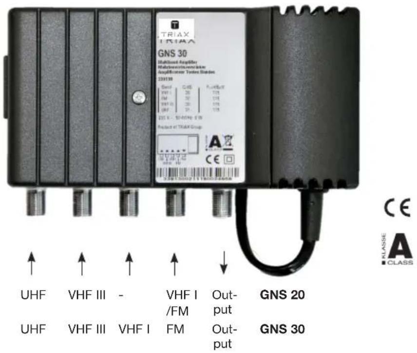
TRIAX TRS140 GNS 30 MultiBand Amplifier MultiBand/Amplifier Amplifier Testes Blades 239138 Band C:65 P:40P:07 VHF I 20 118 FM 20 118 VHF I 20 118 235 x - 50-40Hz 0.1W Product at TRIAX Group UHF VHF III - VHF I Output GNS 20 UHF VHF III VHF I FM Output GNS 30 CLASS A ■ CLASSGNS 20 Order No. 339120
GNS 30 Order No. 339130
Description
GNS 20, 30 are low-noise multi-range amplifiers with digital capability, four highly selective range inputs and one output. For use in all small and medium-sized common antenna networks in which terrestrial signals must be amplified.
High amplification and a high output level make the GNS range of amplifiers suitable for both DVB-T and analog antenna signals.
→ You can operate VHF III and UHF alternately or common using the integrated jumper - e.g. when using combination antennas.
Connectable +5 V remote supply to the UHF or VHF III inputs - e.g. for supplying power to active DVB-T antennas.
→ Level controller 0...-20 dB at each input
Low power consumption
Low-noise inputs for DVB-T
→ The die-cast housing with cooling fins reduces the component temperature and thereby increases both service life and reliability
→ HF connections: F sockets, molded
Conforms to the standards EN 60065, EN 50083-3, EN 50083-5, CE
Correct and incorrect use
This unit may only be operated as described in these instructions. Any other form of incorrect
use shall result in all warranty claims being void.
Safety Requirements
CAUTION: Observe the safety requirements of EN 50083 -1
→ Equipotential bonding
The complete system must be provided with equipotential bonding by means of a mechanically stable protective conductor with
a minimum cross-section of 4 mm^2 . There is a connection point at the earthing screw at the right wall bracket.
NOTE: The unit must not be exposed to dripping or splashing water.
Installation
Choose a location and orientation that will not impair the convection cooling of the amplifier:
• Horizontal (cooling fins aligned vertically)
- Uncovered on wall
- Installed in a cabinet only in strict conformance to the permissible ambient
operating temperature (measured in the air stream underneath the amplifier)
→ Wall mounting
- Fixed to brackets by appropriately sized screws (dia. max. 4.8 mm)
• Fixings 158 mm apart
Recycling Information

When this product has reached the end of its useful life, it is to be turned in for proper disposal as electronic refuse in
compliance with the current disposal regulations of your respective city/country/state.
Setting possibilities
The Multiband amplifiers GNS have the following setting possibilities:
Default setting
Level adjuster,
at all inputs 0...20 dB 0 dB
Power supply for the connected terrestrial antennas
input UHF 0 / +5 V 0 V
input VHFIII 0 / +5 V 0 V
Combining the inputs
UHF and VHFIII, e.g.
when using combination
antennas off/on off
Option:
Power supply for the
combined inputs UHF
+ VHFIII (with additional
jumper, not included) 0 / +5V -
Settings are done as follows:
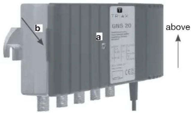
1. Remove the housing lid:
After slackening the central bolt (a) lift the lid off by releasing the catch on the left-hand side (b).
For adjustments now the level adjusters and the jumper on the circuit board are accessible.
Fig. 1 Housing
text_image
b a GNS 20 TRIAX above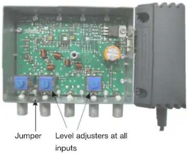
text_image
Jumper Level adjusters at all inputs2. Adjuster elements

no power supply for terrestrial antenna (Default setting)

+5V power supply at UHF

+5V power supply at VHFIII

no power supply UHF + VHFIII common at input UHF

UHF + VHFIII common at input UHF +5V power supply
3. close the housing lid:
Put the housing lid on the housing and press all the way round. The sheet steel segments will now be pressed against the inner wall of the housing. Screw in the central screw.
Technical Data
| Type | GNS 20 | GNS 30 | ||
| Order No. | 339120 | 339130 | ||
| Frequency range | ||||
| Input 1 | - UHF (1) | MHz | 470...862 | 470...862 |
| Input 2 | - VHF III | MHz | 174...230 | 174...230 |
| Input 3 | - VHF I MHz | - 47...68 | ||
| - UHF (2) MHz | - - | |||
| Input 4 | - FM | MHz | 47...68 and | - |
| - VHF I MHz | 87,5...108 | 87,5...108 | ||
| option: input 1 and input 2 combined with jumper | MHz | 470...862 and 174...230 | 470...862 and 174...230 | |
| Gain * | ||||
| Input 1 | - UHF (1) | dB | 22 | 31 |
| Input 2 | - VHF III dB 20 30 | |||
| Input 3 | - VHF I | dB | - | 30 |
| - UHF (2) | dB | - | - | |
| Input 4 | - FM / VHF I | dB 20 30 | ||
| Level controller at all inputs | dB | 0...-20 | 0...-20 | |
| Noise figure * | ||||
| Input 1 | - UHF (1) | dB | 4 | 4 |
| Input 2 | - VHF III dB 4 | 4 | ||
| Input 3 | - VHF I | dB | - | 4 |
| - UHF (2) | dB | - | - | |
| Input 4 | - FM / VHF I | dB | 4 | 4 |
| Output level, IMR = 60 dB * | ||||
| IMR 3 acc. EN 50083-5 | dBμV | 113 | 115 | |
| IMR 2 acc. EN 50083-3 | dBμV | 102 | 105 | |
| Power supply Supply voltage (50 - 60 Hz) Power consumption | V~ W 3,5 | 230 ±10% 6 | 230 ±10% | |
| Ambient conditions acc. EN 60065 | ||||
| Operating temperatur range | °C | -25 ... +55 | -25 ... +55 | |
| Degree of protection | II, isolated guard | II, isolated guard | ||
| Protection class | IP 20 | IP 20 | ||
| MTBF (Belcore @ 25°C) | h 300.000 | 300.000 | ||
| Housing | ||||
| Weight | kg | ca. 0.68 | ca. 0.68 | |
| Dimensions W x H x D | mm | 150 x 80 x 50 | 150 x 80 x 50 | |
| HF connections 75 Ω | F connectors | F connectors | ||
| Screening acc. EN 50083-2 | class A | class A | ||
triax.com/support