
E3MOPT004 - Inverter APC - Free user manual and instructions
Find the device manual for free E3MOPT004 APC in PDF.


User questions about E3MOPT004 APC
0 question about this device. Answer the ones you know or ask your own.
Ask a new question about this device
Download the instructions for your Inverter in PDF format for free! Find your manual E3MOPT004 - APC and take your electronic device back in hand. On this page are published all the documents necessary for the use of your device. E3MOPT004 by APC.
USER MANUAL E3MOPT004 APC
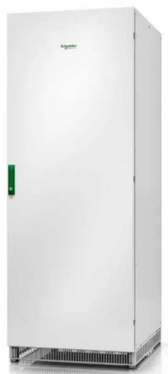
Classic Battery Cabinet
Installation
E3MCBC7A, E3MCBC7B, E3MCBC10A, E3MCBC10B, E3MCBC10C, E3MCBC10D, E3MCBC10E
10/2019
natural_image
Exterior view of a white industrial control cabinet with visible cooling fins and a green door (no text or symbols)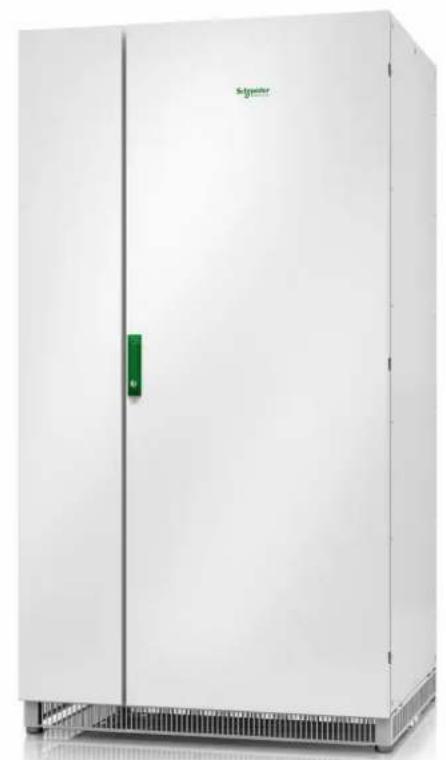
natural_image
Exterior view of a white industrial enclosure with a green control panel and label 'Sagvier' on the front (no other text or symbols visible)Legal Information
The Schneider Electric brand and any trademarks of Schneider Electric SE and its subsidiaries referred to in this guide are the property of Schneider Electric SE or subsidiaries. All other brands may be trademarks of their respective owners.
This guide and its content are protected under applicable copyright laws and furnished for informational use only. No part of this guide may be reproduced or transmitted in any form or by any means (electronic, mechanical, photocopying, recording, or otherwise), for any purpose, without the prior written permission of Schneider Electric.
Schneider Electric does not grant any right or license for commercial use of the or its content, except for a non-exclusive and personal license to consult it on ar is" basis. Schneider Electric products and equipment should be installed, operated, serviced, and maintained only by qualified personnel.
As standards, specifications, and designs change from time to time, information contained in this guide may be subject to change without notice.
To the extent permitted by applicable law, no responsibility or liability is assumed Schneider Electric and its subsidiaries for any errors or omissions in the information content of this material or consequences arising out of or resulting from the use information contained herein.

text_image
Green QR code image, scannable for digital information retrievalGo to http://www.productinfo.schneider-electric.com/portals/ui/easyups3m/ for translations.
Important Safety Instructions — SAVE THESE
INSTRUCTIONS....5
Safety Precautions 6
Electrical Safety....8
Battery Safety....9
Specifications 11
Classic Battery Cabinet Specifications 11
Trip Settings.... 11
Recommended Cable Sizes 13
Torque Specifications....14
Classic Battery Cabinet Weights and Dimensions ....14
Classic Battery Cabinet Shipping Weights and Dimensions....14
Environment....15
Clearance 15
Installation Procedure 16
Receiving....16
Unpack the Cabinet 16
Optional Cable Kits for Line-Up Solutions ....17
Connect the Signal Cables 18
Connect the Power Cables....21
Final Installation 23
Important Safety Instructions — SAVE THESE INSTRUCTIONS
Read these instructions carefully and look at the equipment to become familiar with it before trying to install, operate, service or maintain it. The following safe messages may appear throughout this manual or on the equipment to warn of potential hazards or to call attention to information that clarifies or simplifies a procedure.
The addition of this symbol to a “Danger” or “Warning” safety message indicates that an electrical hazard exists which will result in personal injury if the instructions are not followed.

This is the safety alert symbol. It is used to alert you to potential personal injury hazards. Obey all safety messages with this symbol to avoid possible injury or death.
⚠️ DANGER
DANGER indicates a hazardous situation which, if not avoided, will result in death or serious injury.
Failure to follow these instructions will result in death or serious injury.
▲WARNING
WARNING indicates a hazardous situation which, if not avoided, could result in death or serious injury.
Failure to follow these instructions can result in death, serious injury, or equipment damage.
▲CAUTION
CAUTION indicates a hazardous situation which, if not avoided, could result in minor or moderate injury.
Failure to follow these instructions can result in injury or equipment damage.
NOTICE
NOTICE is used to address practices not related to physical injury. The safety alert symbol shall not be used with this type of safety message.
Failure to follow these instructions can result in equipment damage.
Please Note
Electrical equipment should only be installed, operated, serviced, and maintained by qualified personnel. No responsibility is assumed by Schneider Electric for an consequences arising out of the use of this material.
A qualified person is one who has skills and knowledge related to the construct installation, and operation of electrical equipment and has received safety training to recognize and avoid the hazards involved.
Safety Precautions
⚠️ DANGER
HAZARD OF ELECTRIC SHOCK, EXPLOSION, OR ARC FLASH
Read all instructions in the installation manual before installing or working on this product.
Failure to follow these instructions will result in death or serious injury.
⚠️ DANGER
HAZARD OF ELECTRIC SHOCK, EXPLOSION, OR ARC FLASH
Do not install the product until all construction work has been completed and the installation room has been cleaned.
Failure to follow these instructions will result in death or serious injury.
⚠️ DANGER
HAZARD OF ELECTRIC SHOCK, EXPLOSION, OR ARC FLASH
The product must be installed according to the specifications and requirements as defined by Schneider Electric. It concerns in particular the external and internal protections (upstream breakers, battery breakers, cabling, etc.) and environmental requirements. No responsibility is assumed by Schneider Electric if these requirements are not respected.
Failure to follow these instructions will result in death or serious injury.
⚠️⚠️ DANGER
HAZARD OF ELECTRIC SHOCK, EXPLOSION, OR ARC FLASH
The UPS system must be installed according to local and national regulations. Install the UPS according to:
- IEC 60364 (including 60364-4-41- protection against electric shock, 60364-4-42 - protection against thermal effect, and 60364-4-43 - protection against overcurrent), or
- NEC NFPA 70, or
• Canadian Electrical Code (C22.1, Part 1)
depending on which one of the standards apply in your local area.
Failure to follow these instructions will result in death or serious injury.
⚠️ DANGER
HAZARD OF ELECTRIC SHOCK, EXPLOSION, OR ARC FLASH
• Install the product in a temperature controlled indoor environment free of conductive contaminants and humidity.
- Install the product on a non-flammable, level and solid surface (e.g. concrete) that can support the weight of the system.
Failure to follow these instructions will result in death or serious injury.
⚠️ DANGER
HAZARD OF ELECTRIC SHOCK, EXPLOSION, OR ARC FLASH
The product is not designed for and must therefore not be installed in the following unusual operating environments:
- Damaging fumes
- Explosive mixtures of dust or gases, corrosive gases, or conductive or radiant heat from other sources
- Moisture, abrasive dust, steam or in an excessively damp environment
- Fungus, insects, vermin
- Salt-laden air or contaminated cooling refrigerant
- Pollution degree higher than 2 according to IEC 60664-1
- Exposure to abnormal vibrations, shocks, and tilting
- Exposure to direct sunlight, heat sources, or strong electromagnetic fields Failure to follow these instructions will result in death or serious injury.
⚠️ DANGER
HAZARD OF ELECTRIC SHOCK, EXPLOSION, OR ARC FLASH
Do not drill or cut holes for cables or conduits with the gland plates installed do not drill or cut holes in close proximity to the UPS.
Failure to follow these instructions will result in death or serious
installed
injury.
⚠ WARNING
HAZARD OF ARC FLASH
Do not make mechanical changes to the product (including removal of cabinet parts or drilling/cutting of holes) that are not described in the installation manual
Failure to follow these instructions can result in death, serious injury, or equipment damage.
NOTICE
RISK OF OVERHEATING
Respect the space requirements around the product and do not cover the ventilation openings when the product is in operation.
Failure to follow these instructions can result in equipment damage.
Electrical Safety
⚠️ DANGER
HAZARD OF ELECTRIC SHOCK, EXPLOSION, OR ARC FLASH
- Electrical equipment must be installed, operated, serviced, and maintained only by qualified personnel.
- Apply appropriate personal protective equipment (PPE) and follow safe electrical work practices.
- Turn off all power supplying the UPS system before working on or inside the equipment.
- Before working on the UPS system, check for hazardous voltage between all terminals including the protective earth.
- The UPS contains an internal energy source. Hazardous voltage can be present even when disconnected from the mains supply. Before installing or servicing the UPS system, ensure that the units are OFF and that mains and batteries are disconnected. Wait five minutes before opening the UPS to allow the capacitors to discharge.
- The UPS must be properly earthed/grounded and due to a high leakage current, the earthing/grounding conductor must be connected first.
Failure to follow these instructions will result in death or serious injury.
⚠️ DANGER
HAZARD OF ELECTRIC SHOCK, EXPLOSION, OR ARC FLASH
In systems where backfeed protection is not part of the standard design, an automatic isolation device (backfeed protection option or other device meeting the requirements of IEC/EN 62040-1 or UL1778 5th Edition – depending on which of the two standards apply to your local area) must be installed to prevent hazardous voltage or energy at the input terminals of the isolation device. The device must open within 15 seconds after the upstream power supply fails and must be rated according to the specifications.
Failure to follow these instructions will result in death or serious injury.
When the UPS input is connected through external isolators that, when opened, isolate the neutral or when the automatic backfeed isolation is provided external to the equipment or is connected to an IT power distribution system, a label must be fitted at the UPS input terminals, and on all primary power isolators installed remote from the UPS area and on external access points between such isolators and the UPS, by the user, displaying the following text (or equivalent in a language which is acceptable in the country in which the UPS system is installed):
⚠️ DANGER
HAZARD OF ELECTRIC SHOCK, EXPLOSION, OR ARC FLASH
Risk of Voltage Backfeed. Before working on this circuit: Isolate the UPS and check for hazardous voltage between all terminals including the protective earth.
Failure to follow these instructions will result in death or serious injury.
Battery Safety
⚠️ DANGER
HAZARD OF ELECTRIC SHOCK, EXPLOSION OR ARC FLASH
- Battery circuit breakers must be installed according to the specifications and requirements as defined by Schneider Electric.
- Servicing of batteries must only be performed or supervised by qualified personnel knowledgeable of batteries and the required precautions. Keep unqualified personnel away from batteries.
- Disconnect charging source prior to connecting or disconnecting battery terminals.
- Do not dispose of batteries in a fire as they can explode.
- Do not open, alter, or mutilate batteries. Released electrolyte is harmful to the skin and eyes. It may be toxic.
Failure to follow these instructions will result in death or serious injury.
⚠️ DANGER
HAZARD OF ELECTRIC SHOCK, EXPLOSION, OR ARC FLASH
Batteries can present a risk of electric shock and high short-circuit current. The following precautions must be observed when working on batteries
- Remove watches, rings, or other metal objects.
- Use tools with insulated handles.
- Wear protective glasses, gloves and boots.
- Do not lay tools or metal parts on top of batteries.
- Disconnect the charging source prior to connecting or disconnecting battery terminals.
- Determine if the battery is inadvertently grounded. If inadvertently grounded, remove source from ground. Contact with any part of a grounded battery can result in electric shock. The likelihood of such shock can be reduced if such grounds are removed during installation and maintenance (applicable to equipment and remote battery supplies not having a grounded supply circuit).
Failure to follow these instructions will result in death or serious injury.
⚠️ DANGER
HAZARD OF ELECTRIC SHOCK, EXPLOSION, OR ARC FLASH
When replacing batteries, always replace with the same type and number of batteries or battery packs. Refer to the label in the classic battery cabinet for information on batteries in your system.
Failure to follow these instructions will result in death or serious injury.
▲CAUTION
RISK OF EQUIPMENT DAMAGE
- Wait until the system is ready to be powered up before installing batteries in the system. The time duration from battery installation until the UPS system is powered up must not exceed 72 hours or 3 days.
- Batteries must not be stored more than six months due to the requirement of recharging. If the UPS system remains de-energized for a long period, we recommend that you energize the UPS system for a period of 24 hours at least once every month. This charges the batteries, thus avoiding irreversible damage.
Failure to follow these instructions can result in injury or equipment damage.
Specifications
NOTICE
HAZARD OF EQUIPMENT DAMAGE
Refer to the UPS installation manual for detailed specifications for the UPS system.
Failure to follow these instructions can result in equipment damage.
Classic Battery Cabinet Specifications
⚠️ DANGER
HAZARD OF ELECTRIC SHOCK, EXPLOSION OR ARC FLASH
The classic battery cabinet must only be used with the Easy UPS 3M.
Failure to follow these instructions will result in death or serious injury.
| Classic Battery Solution Battery Type Battery | Breaker Number of Battery | Blocks |
| E3MCBC7A SWL1100 Compact NSX250S DC | 40 | |
| E3MCBC7B XP12V1800 Compact NSX250S DC | 36 | |
| E3MCBC10A XP12V2500 Compact NSX400S DC | 36 | |
| E3MCBC10B XP12V3000 Compact NSX400S DC | 36 | |
| E3MCBC10C XP12V3000 Compact NSX400S DC | 40 | |
| E3MCBC10D XP12V2500 Compact NSX630S DC | 2x36 | |
| E3MCBC10E XP12V3000 Compact NSX630S DC | 2x36 |
Trip Settings
60-100 kVA UPS
| Classic Battery Solution | Battery Breaker 60 kVA | UPS 80 kVA UPS 100 kVA UPS | |||||
| Ir (A) | Im (A) | Ir (A) | Im (A) | Ir (A) | Im (A) | ||
| E3MCBC7A | Compact NSX250S DC (LV438219+LV430100) | 160 | 440 (fixed) | 180 | 440 (fixed) | - | - |
| 2xE3MCBC7A | Compact NSX250S DC (LV438219+LV430100) | 140 | 440 (fixed) | 140 | 440 (fixed) | 140 | 440 (fixed) |
| E3MCBC7B | Compact NSX250S DC (LV438219+LV430101) | 200 | 520 (fixed) | 250 | 520 (fixed) | 250 | 520 (fixed) |
| 2xE3MCBC7B | Compact NSX250S DC (LV438219+LV430101) | 175 | 520 (fixed) | 175 | 520 (fixed) | 175 | 520 (fixed) |
| E3MCBC10A Compact | NSX400S DC (LV438272) | 280 | 1000 | 280 | 1000 | 320 | 1000 |
60-100 kVA UPS (Continued)
| Classic Battery Solution | Battery Breaker 60 kVA | UPS 80 kVA UPS 100 kVA UPS | |||||||
| Ir (A) Im | (A) Ir (A) Im | (A) Ir (A) | Im (A) | ||||||
| E3MCBC10B Compact | NSX400S DC(LV438272) | 280 1000 | 280 1000 | 320 | 1000 | ||||
| E3MCBC10C Compact | NSX400S DC(LV438272) | 280 1000 | 280 1000 | 280 | 1000 | ||||
| E3MCBC10D Compact | NSX630S DC(LV438274) | 420 1500 | 420 1500 | 420 | 1500 | ||||
| E3MCBC10E Compact | NSX630S DC(LV438274) | 420 1500 | 420 1500 | 420 | 1500 | ||||
120-200 kVA UPS
| Classic Battery Solution | Battery Breaker 120 kVA UPS 160 kVA UPS | 200 kVA UPS | ||||||
| 2xE3MCBC7A Compact | NSX250S DC (LV438219) | 160 440 (fixed) | - - - - - | |||||
| 2 × E3MCBC7B^1 | Compact NSX250S DC (LV438219) | 200 520 (fixed) | 250 520 (fixed) | - | - | |||
| E3MCBC10A Compact | NSX400S DC (LV438272) | 360 1000 | - - - - - | |||||
| 2 × E3MCBC10A^1 | Compact NSX400S DC (LV438272) | 280 1000 | 280 1000 | 320 1000 | ||||
| E3MCBC10B Compact | NSX400S DC (LV438272) | 360 1000 | - - - - - | |||||
| 2 × E3MCBC10B^1 | Compact NSX400S DC (LV438272) | 280 1000 | 280 1000 | 320 1000 | ||||
| E3MCBC10C Compact | NSX400S DC (LV438272) | 320 1000 | 400 1000 | 400 1000 | ||||
| 2 × E3MCBC10C^1 | Compact NSX400S DC (LV438272) | 280 1000 | 280 1000 | 280 1000 | ||||
| E3MCBC10D Compact | NSX630S DC (LV438274) | 420 1500 | 480 1500 | 600 1500 | ||||
| 2 × E3MCBC10D^1 | Compact NSX630S DC (LV438274) | 420 1500 | 420 1500 | 420 1500 | ||||
| E3MCBC10E Compact | NSX630S DC (LV438274) | 420 1500 | 480 1500 | 600 1500 | ||||
| 2 × E3MCBC10E^1 | Compact NSX630S DC (LV438274) | 420 1500 | 420 1500 | 420 1500 | ||||
| E3MCBC10A+ E3MCBC10D^2 | Compact NSX400S DC (LV438272) | 280 280 | 280 280 | 280 | 280 | |||
| Compact NSX630S DC (LV438274) | 420 420 | 420 420 | 420 | 420 | ||||
| E3MCBC10B+ E3MCBC10E^2 | Compact NSX400S DC (LV438272) | 280 280 | 280 280 | 280 | 280 | |||
| Compact NSX630S DC (LV438274) | 420 420 | 420 420 | 420 | 420 | ||||
Recommended Cable Sizes
⚠️ DANGER
HAZARD OF ELECTRIC SHOCK, EXPLOSION, OR ARC FLASH
All wiring must comply with all applicable national and/or electrical codes. The maximum allowable cable size is 70 mm ^2 .
Failure to follow these instructions will result in death or serious injury.
NOTE: Overcurrent protection is to be provided by others.
Cable sizes in this manual are based on table B.52.3 (52–C2) of IEC 60364–5 with the following assertions:
- 90 °C conductors
• An ambient temperature of 30 °C
• Use of copper conductors
• Installation method C
Protective Earth (PE) cables are sized in accordance with table 54.3 of IEC 60364-4-54, Article 543.
If the ambient temperature is greater than 30 °C , larger conductors are to be selected in accordance with the correction factors of the IEC.
60-100 kVA UPS
| 60 kVA UPS 80 kVA UPS 100 kVA UPS | ||||||
| Classic Battery Solution | DC ± and N (mm2) | PE (mm2) DC ± | and N (mm2) | PE (mm2) DC ± | and N (mm2) | PE (mm2) |
| E3MCBC7A 35 | 16 50 25 | - | - | |||
| 2xE3MCBC7A 35 | 16 35 16 35 16 | |||||
| E3MCBC7B 50 | 25 70 35 70 35 | |||||
| 2xE3MCBC7B 50 | 25 50 25 50 25 | |||||
| E3MCBC10A 2x50 | 50 2x50 50 2x50 50 | |||||
| E3MCBC10B 2x50 | 50 2x50 50 2x50 50 | |||||
| E3MCBC10C | 2x50 50 2x50 50 2x50 50 | |||||
| E3MCBC10D | 2x70 70 2x70 70 2x70 70 | |||||
| E3MCBC10E 2x70 | 70 2x70 70 2x70 70 | |||||
120-200 kVA UPS
| 120 kVA UPS | 160 kVA UPS | 200 kVA UPS | ||||
| Classic Battery Solution | DC ± and N (mm2) | PE (mm2) DC ± | and N (mm2) | PE (mm2) DC ± | and N (mm2) | PE (mm2) |
| 2xE3MCBC7A3 | 35 16 50 25 | - | - | |||
| 2xE3MCBC7B3 | 70 35 70 35 70 | 35 | ||||
| E3MCBC10A 120 | 70 | -- -- -- | ||||
| 2xE3MCBC10A3 | 95 50 95 50 120 | 70 | ||||
| E3MCBC10B 120 | 70 | -- -- -- | ||||
| 2xE3MCBC10B3 | 95 50 95 50 120 | 70 | ||||
| E3MCBC10C | 95 | 50 | 150 or 2x70 | 95 | 150 or 2x70 | 95 |
| 2xE3MCBC10C3 | 95 50 95 50 95 | 50 | ||||
| E3MCBC10D | 150 or 2x70 | 95 | 2x95 | 95 | 2x120 | 120 |
| 120 kVA UPS 160 kVA UPS 200 kVA UPS | ||||||
| Classic Battery Solution | DC ± and N (mm2) | PE (mm2) DC ± | and N (mm2) | PE (mm2) DC ± | and N (mm2) | PE (mm2) |
| 2xE3MCBC10D4 | 150 95 150 95 | 150 95 | ||||
| E3MCBC10E 150 | or 2x70 95 2x95 | 95 2x120 120 | ||||
| 2xE3MCBC10E4 | 150 95 150 95 | 150 95 | ||||
| E3MCBC10A+E3MCBC10D5 | 95 95 95 95 95 | 95 | ||||
| 150 150 150 150 | 150 150 | |||||
| E3MCBC10B+E3MCBC10E5 | 95 95 95 95 95 | 95 | ||||
| 150 150 150 150 | 150 150 | |||||
Torque Specifications
| Bolt size Torque | |
| M4 | 1.7 Nm (1.25 lb-ft / 15 lb-in) |
| M5 | 2.2 Nm (1.62 lb-ft / 19.5 lb-in) |
| M6 | 5 Nm (3.69 lb-ft / 44.3 lb-in) |
| M8 | 17.5 Nm (12.91 lb-ft / 154.9 lb-in) |
| M10 | 30 Nm (22 lb-ft / 194.7 lb-in) |
Classic Battery Cabinet Weights and Dimensions
| Maximum Weight kg | Height mm (in) | Width mm (in) | Depth mm (in) | |
| E3MCBC7A | 736 | 1900 | 710 | 845 |
| E3MCBC7B | 909 | 1900 | 710 | 845 |
| E3MCBC10A | 1097 | 1900 | 1010 | 845 |
| E3MCBC10B | 1277 | 1900 | 1010 | 845 |
| E3MCBC10C | 1404 | 1900 | 1010 | 845 |
| E3MCBC10D | 1100 | 1900 | 1010 | 845 |
| 1082 | 1900 | 1010 | 845 | |
| E3MCBC10E | 1280 | 1900 | 1010 | 845 |
| 1262 | 1900 | 1010 | 845 |
Classic Battery Cabinet Shipping Weights and Dimensions
| Weight kg | Height mm | Width mm | Depth mm | |
| E3MCBC7A | 756 | 1980 | 815 | 970 |
| E3MCBC7B | 929 | 1980 | 815 | 970 |
| E3MCBC10A | 1117 | 1980 | 1130 | 970 |
| E3MCBC10B | 1297 | 1980 | 1130 | 970 |
| Weight kg Height mm | Width mm Depth mm | |||
| E3MCBC10C 1424 1980 | 1130 970 | |||
| E3MCBC10D 1120 1980 | 1130 970 | |||
| 1102 1980 1130 970 | ||||
| E3MCBC10E 1300 1980 | 1130 970 | |||
| 1282 1980 1130 970 |
Environment
NOTE: The distance between the battery bank and the UPS must not exceed 200 m. Contact Schneider Electric for installations with a longer distance.
| Operating Storage | ||
| Temperature 0 °C to 40 °C (32 °F to | 104 °F) -15 °C to 40 °C (5 °F to 104 °F) | |
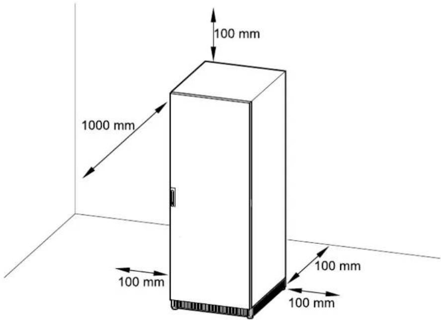
Clearance
NOTE: Clearance dimensions are published for airflow and service access only. Consult with the local safety codes and standards for additional requirements in your local area.
NOTE: The room should be ventilated to prevent the concentration of the dihydrogen generated by the battery cabinet. Recommended minimum airflow: 2.41 m.
text_image
100 mm 1000 mm 100 mm 100 mm 100 mmInstallation Procedure
- Unpack the Cabinet, page 16.
- Connect the Signal Cables, page 18.
- Connect the Power Cables, page 21.
Receiving
External Inspection
When the shipment arrives, inspect the shipping material for any signs of damage or mishandling. Check tilt and impact indicators. Do not attempt to install the system if a damage is apparent. If any damage is noted, contact Schneider Electric and file a damage claim with the shipping agency within 24 hours.
Compare the components of the shipment with the bill of lading. Report any missing items to the carrier and to Schneider Electric immediately.
Verify that labelled units match the order confirmation.
Unpack the Cabinet
- Remove the indicated bolts.
- Lift up the cabinet with a forklift and remove the pallet parts.

text_image
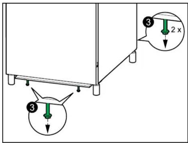
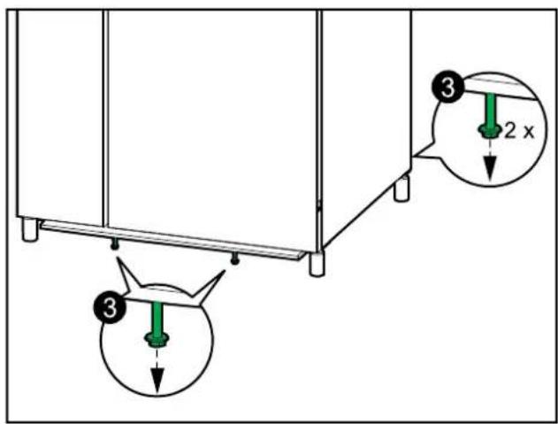
Technical diagram showing a mechanical assembly with labeled components and directional arrows indicating motion or force.- Lower the cabinet to the floor and remove the indicated bolts.
700 mm Wide Classic Battery Cabinet
text_image
Diagram showing three labeled mechanical components with annotations and directional arrows, likely illustrating a system or assembly process.1000 mm Wide Classic Battery Cabinet
text_image
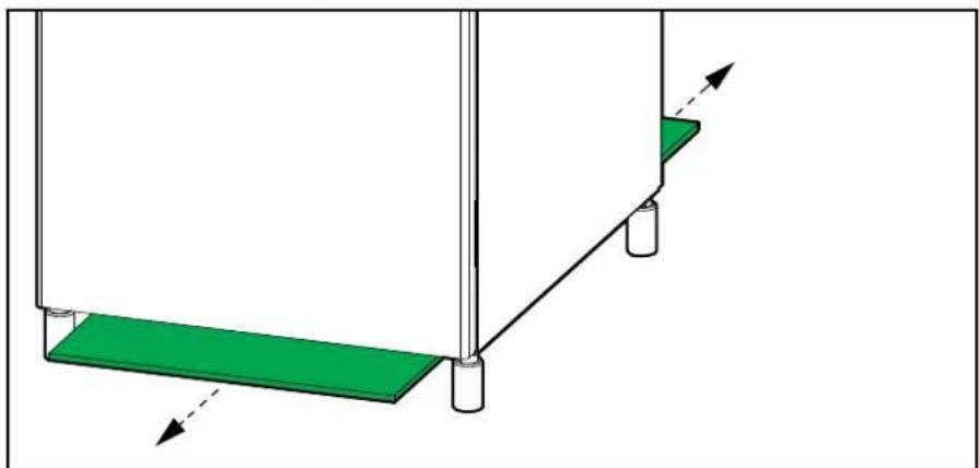
Technical diagram showing a mechanical assembly with three labeled components and a 2x magnified detail view.- Remove the wooden plates.
natural_image
Diagram of a mechanical setup with a green base and vertical supports, showing motion arrows (no text or symbols)Optional Cable Kits for Line-Up Solutions
Two cable kits are available:
- E3MOPT003: Cable kit that includes power cables and signal cables for installation of one classic battery cabinet adjacent to the 60–100 kVA UPS. This cable kit is for the 700 mm wide Easy UPS 3M Classic Battery Cabi
- E3MOPT004: Cable kit that includes power cables and signal cables for installation of one classic battery cabinet adjacent to the 60–100 kVA UPS. This cable kit is for the 1000 mm wide Easy UPS 3M Classic Battery Cat
Connect the Signal Cables
NOTE: Route the signal cables separately from the power cables to ensure sufficient isolation.
NOTE: Use double isolated signal cables. The signal cables must have a minimum rating of 600 V.
NOTE: The length of the battery temperature signal cable is 5m.
- Open the front door of the classic battery cabinet(s).
- Lockout/Tagout the battery breaker.
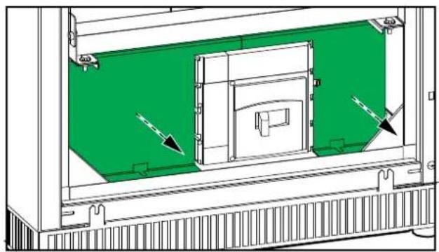
- Remove the left and right breaker protection plates.
700 mm Wide Classic Battery Cabinet
natural_image
Technical diagram of a mechanical enclosure or enclosure with green and white panels, showing internal components and directional arrows (no text or symbols)1000 mm Wide Classic Battery Cabinet
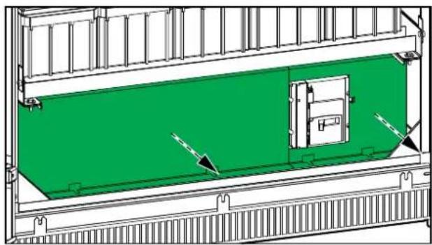
natural_image
Technical diagram of a container or storage unit with green insulation and directional arrows indicating flow or movement (no text or symbols present)- Install the temperature sensor provided with the UPS in the top of the class battery cabinet.
▲WARNING
HAZARD OF FIRE
Position the temperature sensor as described to ensure correct temperature measurements.
Failure to follow these instructions can result in death, serious injury, or equipment damage.
700 mm Wide Classic Battery Cabinet
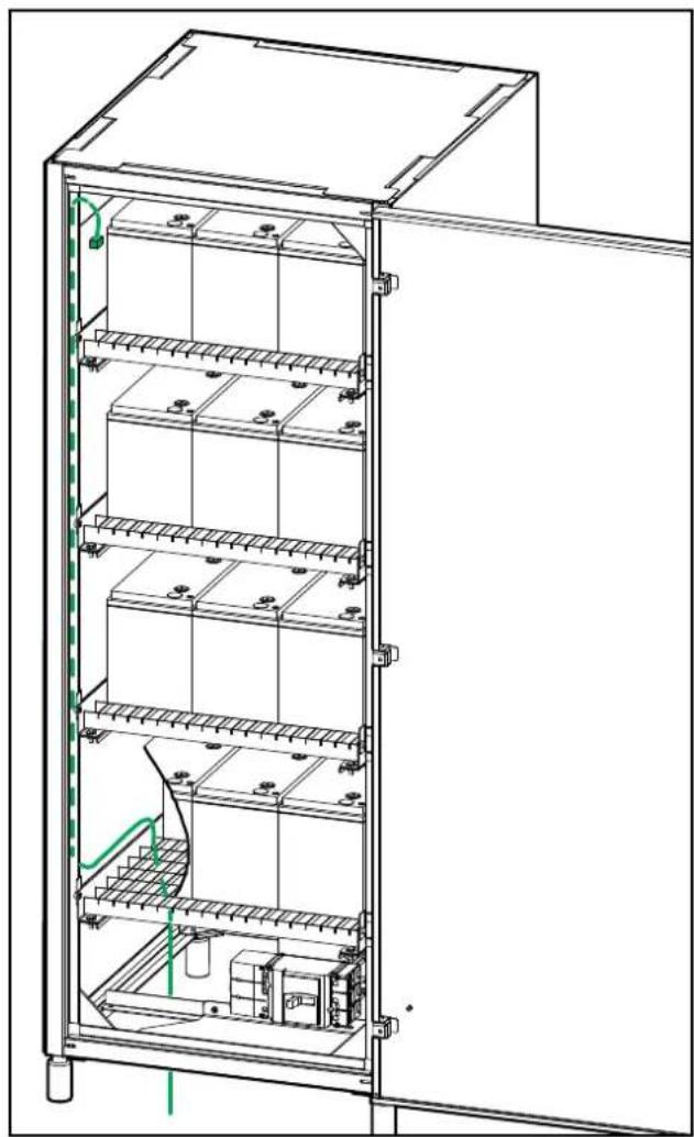
natural_image
Technical line drawing of an open electrical enclosure with internal compartments and wiring (no text or symbols)1000 mm Wide Classic Battery Cabinet
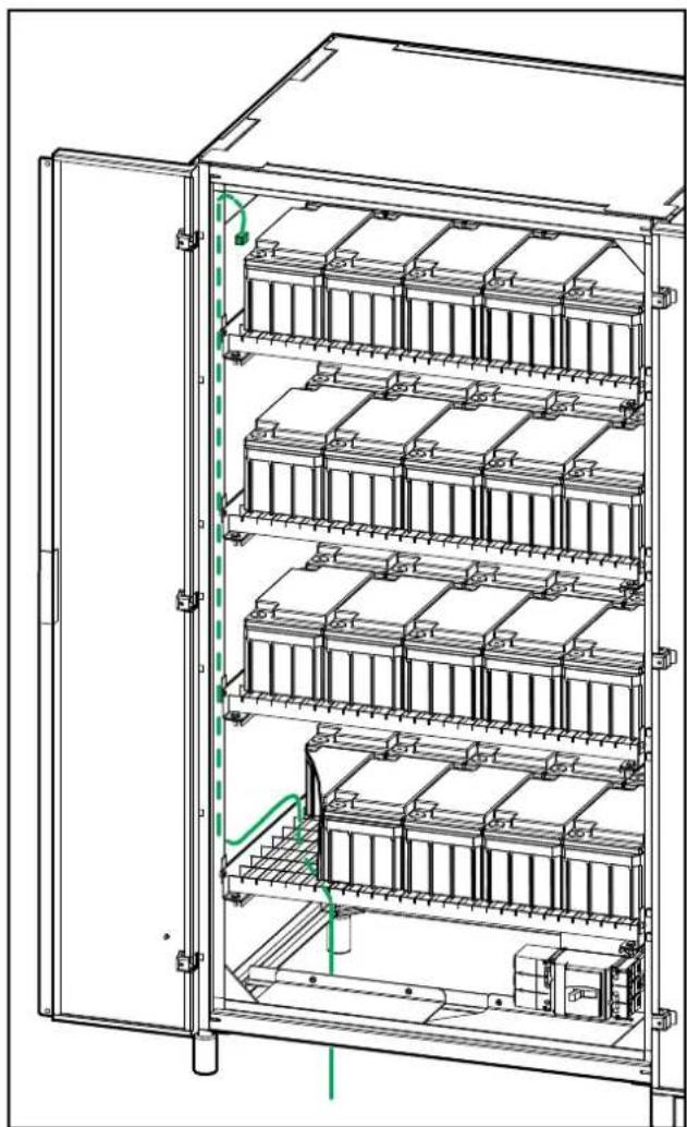
natural_image
Technical line drawing of an open industrial enclosure with multiple battery units and green wiring (no text or symbols)- Route the battery temperature cable through the bottom of the classic batte cabinet to the UPS dry contact terminals BAT_T-1 and BAT_T-2. on the b of the UPS.
- Remove the terminal cover from the left side of the battery breaker.
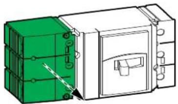
natural_image
Diagram of a device with green and white components, showing internal wiring and a close-up view (no text or symbols)- Remove the cover from the battery breaker and connect the signal cables to the breaker.
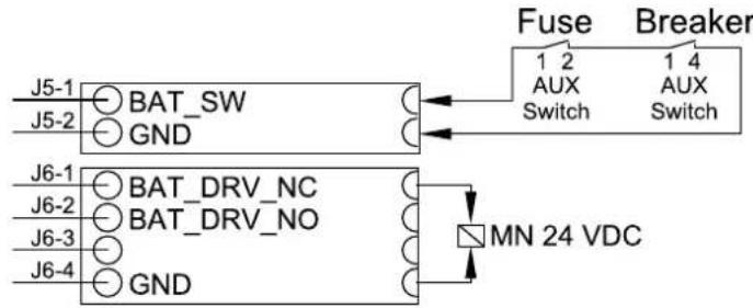
NOTE: AUX switch signal cables and fuse cables are SELV and must be double isolated from the DC cables.
text_image
J5-1 J5-2 BAT_SW GND J6-1 J6-2 J6-3 J6-4 BAT_DRV_NC BAT_DRV_NO GND Fuse Breaker 1 2 AUX Switch 1 4 AUX Switch MN 24 VDC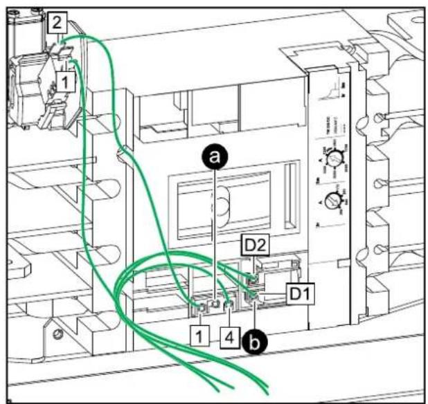
text_image
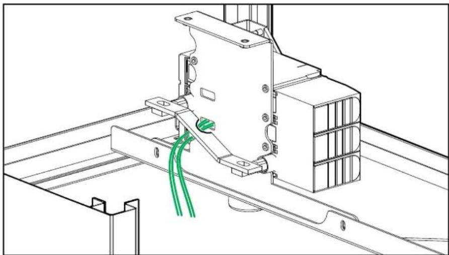
2 1 a D2 D1 1 4 b- Route the signal cables from behind the battery breaker and out through the bottom of the classic battery cabinet and connect the signal cables:
Rear View of the Battery Breaker
natural_image
Technical line drawing of a mechanical assembly with green cable routing (no text or symbols)a. Connect the AUX switch signal cables from the classic battery cabinet to J5-1 and J5-2 in the UPS.
b. Connect the undervoltage trip coil signal cables from the battery breaker to J6-1 and J6-4 in the UPS.
c. Fasten the signal cables with cable ties (provided) to the cable relief.
- Reinstall the breaker cover on the battery breaker.
Connect the Power Cables
⚠️ DANGER
HAZARD OF ELECTRIC SHOCK, EXPLOSION, OR ARC FLASH
Perform a total power off of the UPS before connecting the battery cables to classic battery cabinet.
Failure to follow these instructions will result in death or serious injury.
- Lockout/Tagout the battery breaker.
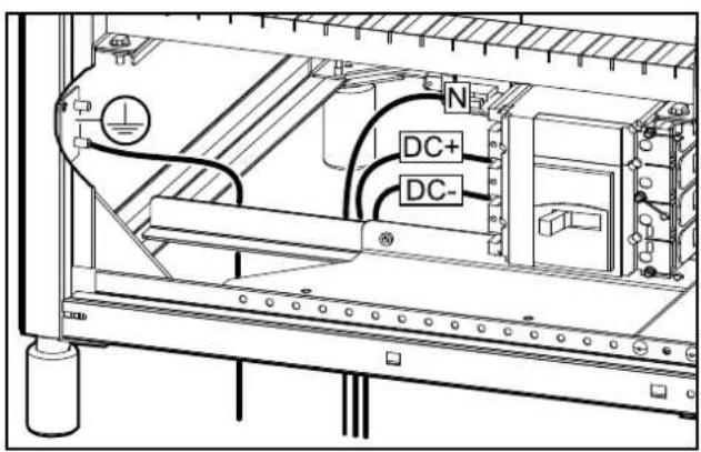
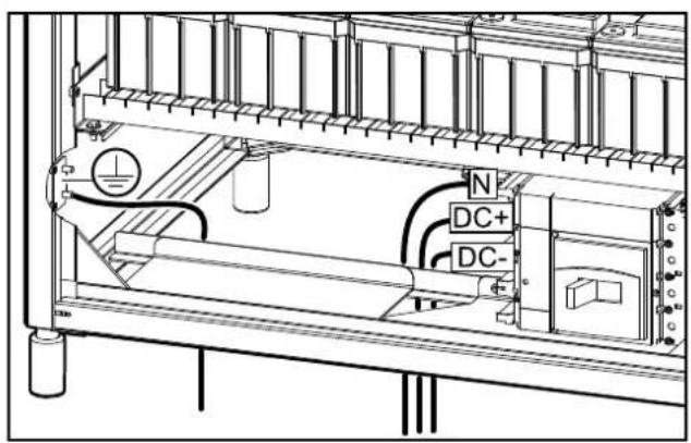
- Route the PE cable through the bottom of the classic battery cabinet and connect the PE cable.
700 mm Wide Classic Battery Cabinet
text_image
N DC+ DC-1000 mm Wide Classic Battery Cabinet
text_image
Technical diagram of a mechanical or electrical assembly with labeled components including DC+, DC-, and N- Route the DC cables from the UPS through the bottom of the classic battery cabinet and connect the battery cables (N, DC+, DC-). Use lock washers (r provided) when connecting the DC cables.
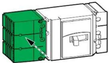
- Reinstall the terminal cover on the left side of the battery breaker and rem the terminal cover from the right side of the battery breaker.
natural_image
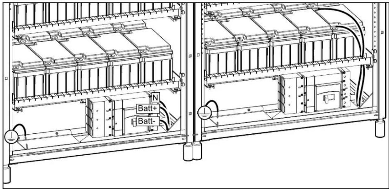
Diagram of a mechanical device with green and white components, showing internal structure and alignment (no text or symbols)- In battery solutions with two classic battery cabinets:
a. Connect the PE cable between the two classic battery cabinets.
b. Connect the battery cables (N, Batt+, Batt-) from the batteries in the classic battery cabinet without a circuit breaker to the right side of the battery breaker in the other classic battery cabinet.
Battery Solution with two 1000 mm Wide Classic Battery Cabinets
text_image
N Batt+ Batt-- Interconnect the batteries on each shelf. Refer to the connection diagram on the inside of the front door.
⚠️ DANGER
HAZARD OF ELECTRIC SHOCK, EXPLOSION, OR ARC FLASH
Batteries can present a risk of electric shock and high short-circuit current. The following precautions must be observed when working on batteries
- Remove watches, rings, or other metal objects.
- Use tools with insulated handles.
- Wear protective glasses, gloves and boots.
- Do not lay tools or metal parts on top of batteries.
- Disconnect the charging source prior to connecting or disconnecting battery terminals.
- Determine if the battery is inadvertently grounded. If inadvertently grounded, remove source from ground. Contact with any part of a grounded battery can result in electric shock. The likelihood of such shock can be reduced if such grounds are removed during installation and maintenance (applicable to equipment and remote battery supplies not having a grounded supply circuit).
Failure to follow these instructions will result in death or serious injury.
- Close the front door of the classic battery cabinet(s).
Final Installation
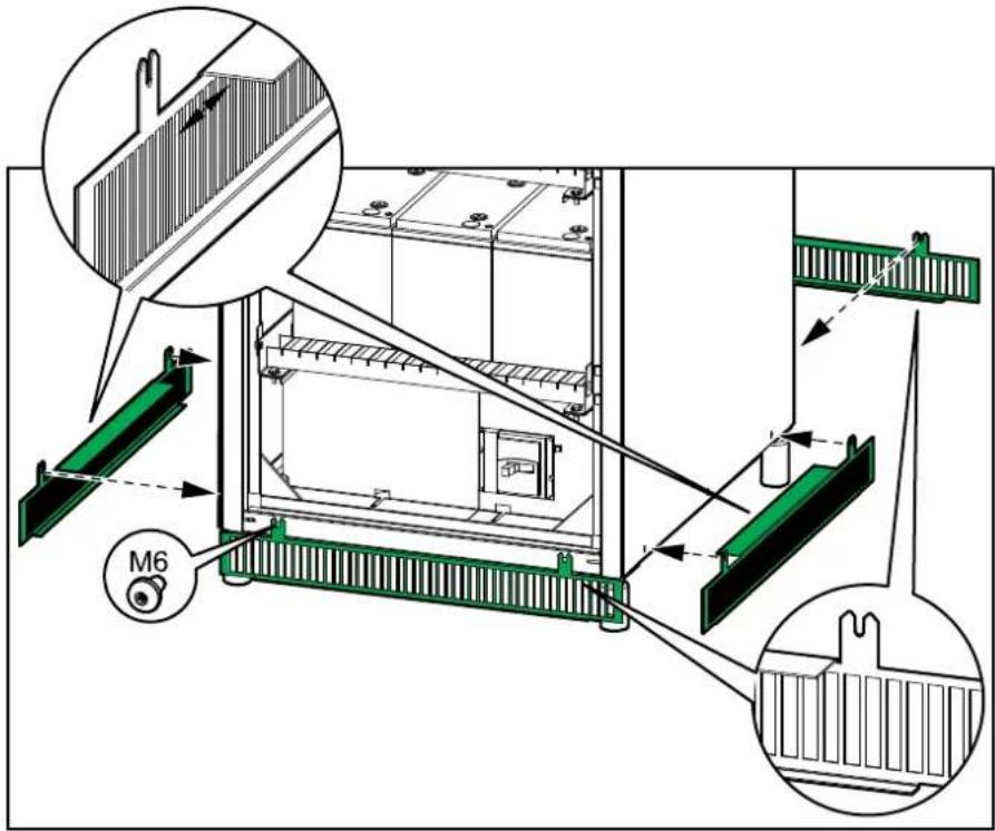
- Install the provided kick plates on the front, rear, and sides of the classic battery cabinet.
text_image
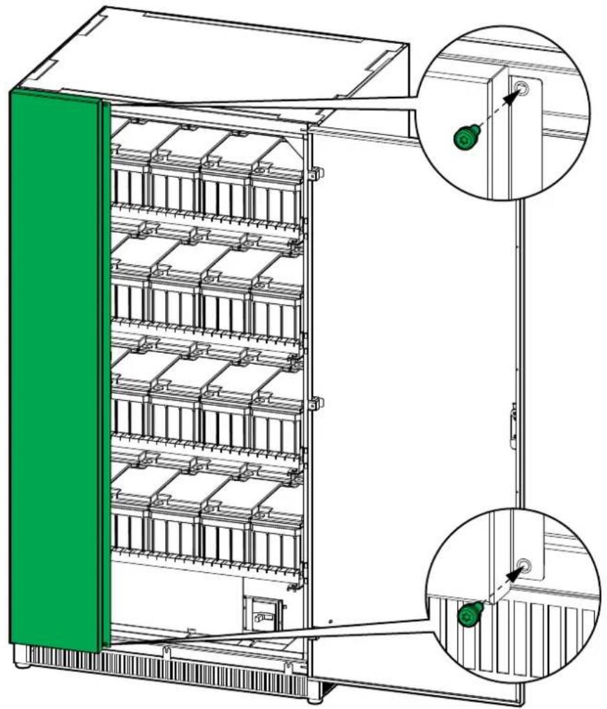
Technical diagram of a battery storage or mounting structure with labeled components and directional arrows indicating flow or movement.- Close the door(s). On the 1000 mm wide classic battery cabinet, install two screws to close the left door.
1000 mm Wide Classic Battery Cabinet
natural_image
Technical line drawing of a multi-level industrial storage unit with green paneling and two inset views showing internal components (no text or symbols)Schneider Electric
As standards, specifications, and design change from time to time, please ask for confirmation of the information given in this publication.