
AT-TQm5403 - Access Point Allied Telesis - Free user manual and instructions
Find the device manual for free AT-TQm5403 Allied Telesis in PDF.


| Product Type | Enterprise Wireless Access Point |
| Model | AT-TQm5403 |
| Brand | Allied Telesis |
| Wireless Standards | 802.11a/b/g/n/ac (Wave 2) |
| Radio Bands | 2.4 GHz (one radio) and 5 GHz (two radios) |
| Maximum Data Rate | Up to 1.3 Gbps on 5 GHz, up to 450 Mbps on 2.4 GHz |
| Ethernet Ports | 2 x 10/100/1000Base-T (LAN1 with PoE+, LAN2) |
| Power over Ethernet | IEEE 802.3at (PoE+) on LAN1 port |
| Maximum Wireless Clients | 127 |
| Virtual Access Points (VAPs) | 8 per radio (up to 24 total) |
| Security | WEP, WPA/WPA2 Personal & Enterprise, MAC address filtering |
| Captive Portal | Click-through, External RADIUS |
| Quality of Service | WMM, EDCA parameters for AP and stations |
| Wireless Distribution System | WDS Bridge (parent/child) |
| Management Interfaces | Web (HTTP/HTTPS), SNMP v1/v2c, Vista Manager EX with AWC plug-in |
| Dimensions (approx.) | 220 x 220 x 45 mm |
| Weight (approx.) | 500 g |
| Operating Temperature | 0°C to 40°C |
| LED Indicators | Power, LAN activity, radio status (Eco mode to disable) |
| Firmware Upgrade | Via web interface |
Frequently Asked Questions - AT-TQm5403 Allied Telesis
User questions about AT-TQm5403 Allied Telesis
0 question about this device. Answer the ones you know or ask your own.
Ask a new question about this device
Download the instructions for your Access Point in PDF format for free! Find your manual AT-TQm5403 - Allied Telesis and take your electronic device back in hand. On this page are published all the documents necessary for the use of your device. AT-TQm5403 by Allied Telesis.
USER MANUAL AT-TQm5403 Allied Telesis
Enterprise-class 802.11ac Wave 2 Wireless Access Points with 2.4GHz and 5GHz Radios
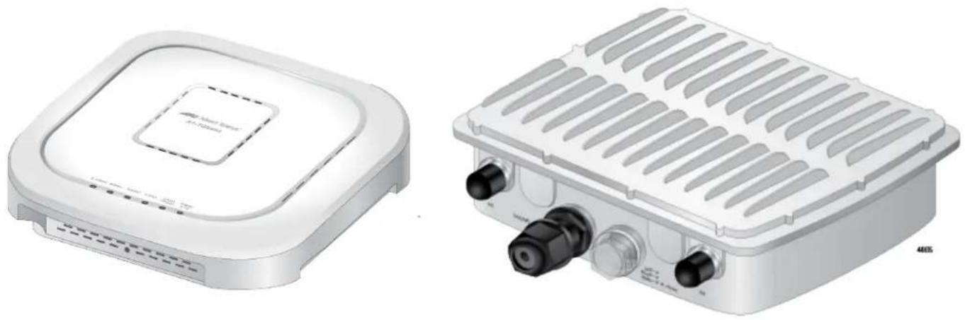
AT-TQ5403
AT-TQm5403
AT-TQ5403e
natural_image
Two white electronic devices with ventilation grilles and ports, one front view and one side view (no visible text or symbols)Management Software User's Guide
Copyright © 2019 Allied Telesis, Inc.
All rights reserved.
This product includes software licensed under the BSD License. As such, the following language applies for those portions of the software licensed under the BSD License:
Redistribution and use in source and binary forms, with or without modification, are permitted provided that the following conditions are met:
* Redistributions of source code must retain the above copyright notice, this list of conditions and the following disclaimer.
* Redistributions in binary form must reproduce the above copyright notice, this list of conditions and the following disclaimer in the documentation and/or other materials provided with the distribution.
* Neither the name of Allied Telesis, Inc. nor the names of the respective companies above may be used to endorse or promote products derived from this software without specific prior written permission.
THIS SOFTWARE IS PROVIDED BY THE COPYRIGHT HOLDERS AND CONTRIBUTORS "AS IS" AND ANY EXPRESS OR IMPLIED WARRANTIES, INCLUDING, BUT NOT LIMITED TO, THE IMPLIED WARRANTIES OF MERCHANTABILITY AND FITNESS FOR A PARTICULAR PURPOSE ARE DISCLAIMED. IN NO EVENT SHALL THE COPYRIGHT HOLDER OR CONTRIBUTORS BE LIABLE FOR ANY DIRECT, INDIRECT, INCIDENTAL, SPECIAL, EXEMPLARY, OR CONSEQUENTIAL DAMAGES (INCLUDING, BUT NOT LIMITED TO, PROCUREMENT OF SUBSTITUTE GOODS OR SERVICES; LOSS OF USE, DATA, OR PROFITS; OR BUSINESS INTERRUPTION) HOWEVER CAUSED AND ON ANY THEORY OF LIABILITY, WHETHER IN CONTRACT, STRICT LIABILITY, OR TORT (INCLUDING NEGLIGENCE OR OTHERWISE) ARISING IN ANY WAY OUT OF THE USE OF THIS SOFTWARE, EVEN IF ADVISED OF THE POSSIBILITY OF SUCH DAMAGE.
Copyright (c) [dates as appropriate to package] by The Regents of the University of California - All rights reserved. Copyright (c) 2000-2003 by Intel Corporation - All rights reserved. Copyright (c) 1997-2003, 2004 by Thomas E. Dickey dickey@invisible-island.net - All rights reserved. Copyright (c) 2001-2009 by Brandon Long (ClearSilver is now licensed under the New BSD License.) Copyright (c) 1984-2000 by Carnegie Mellon University - All rights reserved. Copyright (c) 2002,2003 by Matt Johnston - All rights reserved. Copyright (c) 1995 by Tatu Ylonen ylo@cs.hut.fi - All rights reserved. Copyright 1997-2003 by Simon Tatham. Portions copyright by Robert de Bath, Joris van Rantwijk, Delian Delchev, Andreas Schultz, Jeroen Massar, Wez Furlong, Nicolas Barry, Justin Bradford, and CORE SDI S.A. Copyright (c) 1989, 1991 by Free Software Foundation, Inc. (GNU General Public License, Version 2, June 1991). Copyright (c) 2002-2005 by Jouni Malinen jkmaline@cc.hut.fi and contributors. Copyright (c) 1991, 1999 by Free Software Foundation, Inc. (GNU Lesser General Public License, Version 2.1, February 1999). Copyright (c) 1998-2002 by Daniel Veillard - All rights reserved. Copyright (c) 1998-2004 by The OpenSSL Project - All rights reserved. Copyright (c) 1995-1998 by Eric Young (eay@cryptsoft.com) - All rights reserved.
This product also includes software licensed under the GNU General Public License available from:
http://www.gnu.org/licenses/gpl2.html
Allied Telesis is committed to meeting the requirements of the open source licenses including the GNU General Public License (GPL) and will make all required source code available.
If you would like a copy of the GPL source code contained in this product, please send us a request by registered mail including a check for US\$15 to cover production and shipping costs, and a CD with the GPL code will be mailed to you.
GPL Code Request
Allied Telesis Labs (Ltd)
PO Box 8011
Christchurch, New Zealand
No part of this publication may be reproduced without prior written permission from Allied Telesis, Inc.
Allied Telesis™ and the Allied Telesis logo are trademarks of Allied Telesis, Incorporated.
Ethernet ^™ is a trademark of the Xerox Corporation.
Wi-Fi®, Wi-Fi Alliance®, WMM®, Wi-Fi Protected Access® (WPA), the Wi-Fi CERTIFIED logo, the Wi-Fi logo, the Wi-Fi ZONE logo, and the Wi-Fi Protected Setup logo are registered trademarks of the Wi-Fi Alliance. Wi-Fi CERTIFIED™, Wi-Fi Multimedia™, WPA2™ and the Wi-Fi Alliance logo are trademarks of the Wi-Fi Alliance.
Microsoft is a registered trademark of Microsoft Corporation.
All other product names, company names, logos or other designations mentioned herein are trademarks or registered trademarks of their respective owners.
Allied Telesis, Inc. reserves the right to make changes in specifications and other information contained in this document without prior written notice. The information provided herein is subject to change without notice. In no event shall Allied Telesis, Inc. be liable for any incidental, special, indirect, or consequential damages whatsoever, including but not limited to lost profits, arising out of or related to this manual or the information contained herein, even if Allied Telesis, Inc. has been advised of, known, or should have known, the possibility of such damages.
Contents
Preface 13
Safety Symbols Used in this Document 14
Contacting Allied Telesis 15
Chapter 1: Getting Started .... 17
Features 18
Management Tools....20
Web Browser 20
Vista Manager EX and AWC Plug-in 20
SNMPv1 and v2c....21
Starting the First Management Session 22
Starting the First Management Session with a Direct Connection 23
Starting the First Management Session without a DHCP Server 23
Starting a Management Session 25
Management Windows 27
Main Menu....27
Navigation 28
Sub-menu 28
Content 28
Saving and Applying Your Changes....29
Ending Management Sessions....30
What to Configure First.... 31
Chapter 2: Basic Settings ...... 33
Assigning a Dynamic IP Address from a DHCP Server 34
Assigning a Static IP Address to the Access Point.... 37
Setting the Date and Time with the Network Time Protocol (NTP) 40
Manually Setting the Date and Time 43
Configuring SNMPv1 and v2c 45
Configuring SNMP Traps....49
Enabling or Disabling the LEDs....51
Enabling or Disabling the Reset Button....52
Chapter 3: Web Browser Interface .... 55
Configuring the Web Browser Interface....56
Changing the Manager's Login Name and Password 58
Setting the Language of the Web Browser Interface....60
Chapter 4: 2.4GHz and 5GHz Radios ...... 61
Configuring the Radios 62
Configuring Basic Radio Settings....62
Configuring Advanced Radio Settings....66
Displaying Radio Status 71
Dynamic Frequency Selection....73
Setting the Country Code Setting 74
Selecting the Location 75
Contents
Guidelines to Changing the Location....75
Changing the Location to Outdoor....76
Changing the Location to Indoor....76
Chapter 5: Virtual Access Points ......77
VAP Introduction....78
Configuring Basic VAP Parameters 79
Configuring Captive Portal 84
Captive Portal Configurations 84
Port Numbers....85
Requiring Wireless Clients to Click the Agree Button to Access to the Network 85
Delegating a Proxy Server to Interact with Wireless Clients....87
Delegating RADIUS Servers and a Proxy Server....88
Delegating RADIUS Servers to Authenticate Wireless Clients....90
Creating Pages in HTML for a Proxy Server 91
Requirements for the click_through_login.html and click_through_login_fail.html ......92
HTML Code and Display Examples of Login Page 92
Creating Login Pages in HTML When External RADIUS is Selected....92
Requirements for the radius_login.html and radius_login_fail.html 93
HTML Code and Display Examples of Login Page 93
Configuring VAP Security 94
No Security 94
Static WEP....95
WPA Personal (Pre-Shared Key) 97
WPA Enterprise 100
Configuring VAP Fast Roaming 104
Configuring the MAC Address List....106
Displaying VAP and LAN Ports Statistics 108
Advanced Settings 110
Chapter 6: Quality of Service ....113
Introduction to Quality of Service 114
Configuring QoS Basic Settings....116
Configuring AP EDCA Parameters 117
Configuring Station EDCA Parameters....120
Chapter 7: LAN1 and LAN2 Ports ....123
Configuring the Management VLAN 124
Enabling or Disabling the LAN2 Port 126
Configuring PoE Negotiation with Link Layer Discovery Protocol....128
Displaying the Status of LAN1 and LAN2 Ports....130
Chapter 8: Wireless Distribution System Bridges ....133
Introduction to Wireless Distribution Bridges 134
WDS Bridge Elements 137
Radio 137
VAP0....137
Radio Channel 137
Parents and Children 137
Security 137
Dynamic Frequency Selection 138
Guidelines 139
Preparing Access Points for a WDS Bridge....140
Chapter 9: Monitoring ....143
Displaying Basic System Information....144
Displaying Neighboring Access Points 147
Displaying Associated Clients148
Chapter 10: System Log 149
Displaying the System Log150
Sending Log Messages to a Syslog Server152
Chapter 11: Maintenance 155
Downloading the Configuration of the Access Point to Your Computer156
Restoring a Configuration to the Access Point158
Restoring the Default Settings to the Access Point159
Uploading New Management Software to the Access Point160
Rebooting the Access Point162
Sending Technical Support Information to Allied Telesis163
Contents
List of Figures
Figure 1: Log On Window 25
Figure 2: Sample Management Window 27
Figure 3: Main Menu Button 28
Figure 4: Network DHCP Window 35
Figure 5: Network Static IP Address Window.... 37
Figure 6: Time Window - NTP Option.... 40
Figure 7: Daylight Savings Time Settings.... 42
Figure 8: Time Window - Manually Option 43
Figure 9: SNMP Agent Settings Window 45
Figure 10: Trap Settings Window 49
Figure 11: LED Window....51
Figure 12: Hardware Window....52
Figure 13: Web Window 56
Figure 14: User Window 58
Figure 15: Language Window....60
Figure 16: Basic Radio Settings Window on AT-TQ5403 and AT-TQm5403.... 62
Figure 17: Basic Radio Settings Window on AT-TQ5403e....63
Figure 18: Advanced Radio Settings Window 67
Figure 19: Radio Status Window 71
Figure 20: Virtual Access Point Tab 79
Figure 21: Captive Portal - Click-Through 86
Figure 22: Captive Portal - Using a Proxy Server.... 88
Figure 23: Captive Portal - External RADIUS....89
Figure 24: Captive Portal - External RADIUS....91
Figure 25: Captive Portal - Terms of Service Page Sample.... 92
Figure 26: Captive Portal - Login Page Sample 93
Figure 27: None Selection in the VAP Security Tab.... 94
Figure 28: Static WEP Security Tab 95
Figure 29: WPA Personal Security Tab.... 98
Figure 30: WPA Enterprise Tab.... 100
Figure 31: Fast Roaming Window 104
Figure 32: MAC Address List Window.... 106
Figure 33: Statistics Window 108
Figure 34: Advanced Settings Tab 110
Figure 35: QoS Window 115
Figure 36: LAN Settings Window.... 124
Figure 37: LLDP Window.... 129
Figure 38: LAN1 Window.... 130
Figure 39: LAN2 Window.... 130
Figure 40: WDS Bridge.... 134
Figure 41: Example of Radio and Channel Assignments in a WDS Bridge 135
Figure 42: Example of an Access Point as Both Parent and Child.... 136
Figure 43: System Window.... 144
Figure 44: Neighbor AP Window 147
Figure 45: Associated Client Window.... 148
List of Figures
Figure 46: Log Window for Event Messages .... 151
Figure 47: Log Window for Syslog Client.... 152
Figure 48: Configuration Window.... 156
Figure 49: Upgrade Window 161
Figure 50: Reboot Window 162
Figure 51: Support Window 163
List of Tables
Table 1. TQ5403 Series Access Points Differences ...... 19
Table 2. Network DHCP Window ...... 35
Table 3. Network Static IP Selection Window ...... 38
Table 4. Time Window - NTP Option ...... 41
Table 5. Time Window - Manually Option ...... 44
Table 6. SNMP Agent Settings Window ...... 46
Table 7. SNMP Trap Settings Window 50
Table 8. Default Settings for Reset Button 52
Table 9. Web Window ...... 57
Table 10. Basic Radio Settings Window ...... 63
Table 11. Advanced Radio Settings Window 67
Table 12. Radio Status Window ...... 71
Table 13. Virtual Access Point Tab 80
Table 14. Captive Portal 86
Table 15. Captive Portal - External RADIUS 89
Table 16. Static WEP Security Tab 96
Table 17. WPA Personal Security Tab 98
Table 18. WPA Enterprise Tab 101
Table 19. Fast Roaming Window 105
Table 20. Statistics Window ...... 109
Table 21. Advanced Settings Tab 110
Table 22. QoS Window - Basic Settings 116
Table 23. QoS Window - AP EDCA Parameters 117
Table 24. QoS Window - Station EDCA Parameters ...... 120
Table 25. LAN Settings Window - VLAN Configuration Section 125
Table 26. LAN1 or LAN2 Window 131
Table 27. System Window ...... 144
Table 28. Neighbor AP Window 147
Table 29. Associated Client Window 148
Table 30. Message Severity Levels ...... 150
Table 31. Log Window for Syslog Client 152
List of Tables
This guide contains instructions on how to manage the features of the TQ5403 series access points with the web browser management interface.
The access point models included in this guide are:
□ AT-TQ5403
□ AT-TQm5403
□ AT-TQ5403e
This preface contains the following sections:
☐ “Safety Symbols Used in this Document” on page 14
☐ “Contacting Allied Telesis” on page 15
Safety Symbols Used in this Document
This document uses the following conventions.
Note
Notes provide additional information.

Caution
Cautions inform you that performing or omitting a specific action may result in equipment damage or loss of data.

Warning
Warnings inform you that performing or omitting a specific action may result in bodily injury.

Warning
Laser warnings inform you that an eye or skin hazard exists due to the presence of a Class 1 laser device.
Contacting Allied Telesis
If you need assistance with this product, you can contact Allied Telesis technical support by going to the Support & Services section of the Allied Telesis web site at www.alliedtelesis.com/support. You can find links for the following services on the page:
☐ 24/7 Online Support - Enter our interactive support center to search for answers to your questions in our knowledge database, check support tickets, learn about Return Merchandise Authorizations (RMAs), and contact Allied Telesis technical experts.
☐ USA and EMEA phone support - Select the phone number that best fits your location and customer type.
☐ Hardware warranty information - Learn about Allied Telesis warranties and register your product online.
- Replacement Services - Submit an RMA request via our interactive support center.
□ Documentation - View the most recent installation guides, user guides, software release notes, white papers and data sheets for your product.
☐ Software Updates - Download the latest software releases for your product.
For sales or corporate contact information, select your region and country and then go to www.alliedtelesis.com/contact.
Preface
Chapter 1
Getting Started
Here are the sections in this chapter:
☐ "Features" on page 18
☐ “Management Tools” on page 20
☐ “Starting the First Management Session” on page 22
☐ “Starting a Management Session” on page 25
☐ “Management Windows” on page 27
☐ “Saving and Applying Your Changes” on page 29
☐ “Ending Management Sessions” on page 30
☐ "What to Configure First" on page 31
Features
The TQ5403 series wireless access points have the following features:
□ One 2.4GHz radio
□ Two 5GHz radios
☐ Eight virtual access points per radio
☐ WPA Personal and WPA Enterprise with WPA, WPA2, TKIP, and CCMP authentication and encryption
□ Static WEP encryption
☐ MAC address filter for wireless clients
□ Multicast rate limiting
□ Band steering
□ Automatic channel selection
□ Adjustable transmission power
Fast roaming
Airtime fairness
□ Quality of Service
☐ Wireless Distribution System (WDS) bridges
☐ Channel blankets (AT-TQ5403 and AT-TQ5403e only)
□ DHCP client
☐ RADIUS accounting with external RADIUS server
□ Network Time Protocol client
☐ HTTP and HTTPS web browser management
☐ SNMPv1 and v2c management
□ Event log
□ Syslog client
☐ LAN1 port: 10/100/1000Base-T Ethernet port with Power over Ethernet (PoE), Auto-Negotiation, and auto MDI/MDIX (AT-TQ5403 and AT-TQm5403 only)
☐ LAN2 port: 10/100/1000Base-T Ethernet port with Auto-Negotiation and auto MDI/MDIX (AT-TQ5403 and AT-TQm5403 only)
☐ LAN(PoE) port: 10/100/1000Base-T Ethernet port with IEEE 802.3at PoE+, Auto-Negotiation, and auto MDI/MDIX (AT-TQ5403e only)
☐ Static link aggregation for LAN1 and LAN2 ports (AT-TQ5403 and AT-TQm5403 only)
☐ IEEE 802.3 (10Base-T), IEEE 802.3u (100Base-TX), and IEEE 802.3ab (1000Base-T) compliance on LAN1, LAN2, LAN(PoE) ports.
☐ Outdoor installation on a wall or pole (AT-TQ5403e only)
Table 1 lists the differences among the TQ5403 series access points.
Table 1. TQ5403 Series Access Points Differences
| Access Point Channel Blankets | Maximum Number of Wireless Clients | |
| AT-TQ5403 | Supported ^1 | 200 |
| AT-TQm5403 Not supported 127 | ||
| AT-TQ5403e | Supported ^1 | 200 |
- Requires Vista Manager EX and Autonomous Wireless Controller (AWC) plugin.
Management Tools
The access points support the following management tools.
Web Browser The access point has a web browser management interface for configuring the device from your management workstations. The web browser interface allows you to manage one unit at a time and supports both non-secure HTTP and secure HTTPS management sessions. The default is HTTP.
Note
The product has been tested with Microsoft Windows Internet Explorer Version 9 or later and Microsoft Edge.
Vista Manager EX and AWC Plug-in
The access point is supported with Vista Manager and the Autonomous Wave Control (AWC) plug-in. Configuring and monitoring large numbers of devices is simplified with AWC because you can add multiple devices to management groups and manage them as one unit. The application can also monitor the operations of the access points and automatically adjust operating properties to optimize the performance of your wireless network.
Note
The AT-TQ5403 access point requires Vista Manager 2.4 or later. The AT-TQm5403 and AT-TQ5403e access points require Vista Manager 2.5 or later.
Note
The channel blanket feature of the AT-TQ5403 and AT-TQ5403e access points requires Vista Manager EX and the AWC plug-in.
You cannot configure the following access point settings with Vista Manager EX and the AWC plug-in. These settings require the web browser interface:
□ Hostname
☐ DHCP client or static IP address
□ Domain Name Server name
□ Timezone
□ Daylight savings time
□ System date or time
☐ HTTP and HTTPS modes
□ System name, location, and contact
□ LLDP PoE negotiation
□ Enable or disable the Reset button
SNMPv1 and v2c You can use SNMPv1 or SNMPv2 to view the parameter settings of the devices. The MIB is available from the Allied Telesis web site. For instructions on how to configure the unit for SNMP, refer to “Configuring SNMPv1 and v2c” on page 45 and “Configuring SNMP Traps” on page 49.
Note
You cannot use SNMP to change the parameter settings on the access points.
Note
The access points do not support SNMPv3 or the AT-UWC Wireless LAN Controller.
Starting the First Management Session
Note
If you are using the AT-TQ5403 or AT-TQm5403 access point, use the LAN1 port. If you are using the AT-TQ5403e access point, use the LAN(PoE) port.
After you install and power on the access point, it queries the subnet on the LAN1 or LAN(PoE) port for a DHCP server. If a DHCP server responds to its query, the unit uses the IP address the server assigns to it. If there is no DHCP server, the access point uses the default IP address 192.168.1.230.
If your network has a DHCP server, use the IP address the server assigns it to it to start the management session. For directions, refer to “Starting a Management Session” on page 25
If your network does not have a DHCP server, you can start the first management session by establishing a direct connection between your computer and the unit by connecting an Ethernet cable to the Ethernet port on the computer and the LAN1 or LAN(PoE) port on the access point. This procedure requires changing the IP address on your computer to make it a member of the same subnet as the default IP address on the access point.
The first management session can also be performed while the device is connected to your network. However, If your network does not have a DHCP server, you still have to change the IP address of your computer to match the subnet of the default address of the access point. Furthermore, if your network is divided into virtual LANs (VLANs), you have to be sure to connect the access point and your computer to ports on an Ethernet switch that are members of the same VLAN.
The instructions for starting the first management session are found in the following sections:
☐ "Starting the First Management Session with a Direct Connection" on page 23. This section is for the AT-TQ5403 and AT-TQm5403 models only.
☐ “Starting the First Management Session without a DHCP Server” on page 23
Note
The first management session of the access point has to be conducted through the LAN1 or LAN(PoE) port because the default setting for the radios is off.
Starting the First Management Session with a Direct Connection
To start the management session with a direct Ethernet connection between your computer and the LAN1 port on the access point, perform the following procedure:
Note
This section is for the AT-TQ5403 and AT-TQm5403 models only.
Note
If the access point is using PoE, you cannot perform this procedure because it requires a direct connection between your computer and the LAN1 port on the access point. If you have the optional power supply, you can connect it to the unit until after you have completed the first management session, or you can perform “Starting the First Management Session without a DHCP Server” on page 23.
- Connect one end of a network cable to the LAN1 port on the access point and the other end to the Ethernet network port on your computer.
- Change the IP address on your computer to 192.168.1.n, where n is a number from 1 to 254, but not 230. Refer to the documentation that accompanies your computer for instructions on how to set the IP address.
- Set the subnet mask on your computer to 255.255.255.0.
- Power on the access point.
- Start the web browser on your computer.
- Enter the IP address 192.168.1.230 in the URL field of the browser and press the Enter key.
You should now see the login window, shown in Figure 1 on page 25. - Enter "manager" for the user name and "friend" for the password. The user name and password are case-sensitive.
- Click the Login button.
Starting the First Management Session without a DHCP Server
This procedure explains how to start the first management session on the access point when the LAN port is connected to an Ethernet switch on a network that does not have a DHCP server. To start the management session, perform the following procedure:
-
To use the PoE feature on the access point, be sure to connect the LAN1 or LAN(PoE) port to a PoE source device.
-
If your network has VLANs, check to be sure that your computer and the access point are connected to ports on the Ethernet switch that are members of the same VLAN. This might require accessing the management software on the switch and listing the VLANs and their port assignments. For example, if the access point is connected to a port that is a member of the Sales VLAN, your computer must be connected to a port that is also a member of that VLAN. If your network is small and does not have VLANs or routers, you can connect your computer to any port on the Ethernet switch.
- Change the IP address on your computer to 192.168.1.n, where n is a number from 1 to 254, but not 230. Refer to the documentation that accompanies your computer for instructions on how to set the IP address.
- Set the subnet mask on your computer to 255.255.255.0.
- Power on the access point.
- Start the web browser on your computer.
- Enter the IP address 192.168.1.230 in the URL field of the browser and press the Return key.
You should now see the logon window, shown in Figure 1 on page 25.
- Enter "manager" for the user name and "friend" for the password. The user name and password are case-sensitive.
- Click the Login button.
Starting a Management Session
This section explains how to start a management session on the access point from your management workstation, using a web browser. The procedure assumes that the access point has already been assigned an IP address, either manually or from a DHCP server.
Note
If the access point is using its default address 192.168.1.230, refer to "Starting the First Management Session" on page 22 for instructions.
To start a management session on the access point, perform the following procedure:
- Open the web browser on your management workstation.
- Enter the IP address of the access point in the URL field of the web browser.
Note
Precede the IP address with HTTPS:// if the access point is already configured for HTTPS management. The default is HTTP management.
See the log on window shown in Figure 1 as an example.

Allied Telesis
AT-TQ5403

User ID

Password

Figure 1. Log On Window
Note
If you use HTTPS management, your web browser might display a warning message stating that the site certificate is invalid. If this occurs, select an appropriate option to continue to the web site. To avoid the message in future management sessions, make the web site a trusted site in your web browser.
- Enter the user name and password for the unit. The default values are "manager" for the user name and "friend" for the password. The user name and password are case-sensitive.
- Click the Login button.
Management Windows
This section has a brief overview of the management windows and menus. The main parts of the management windows are identified in Figure 2.
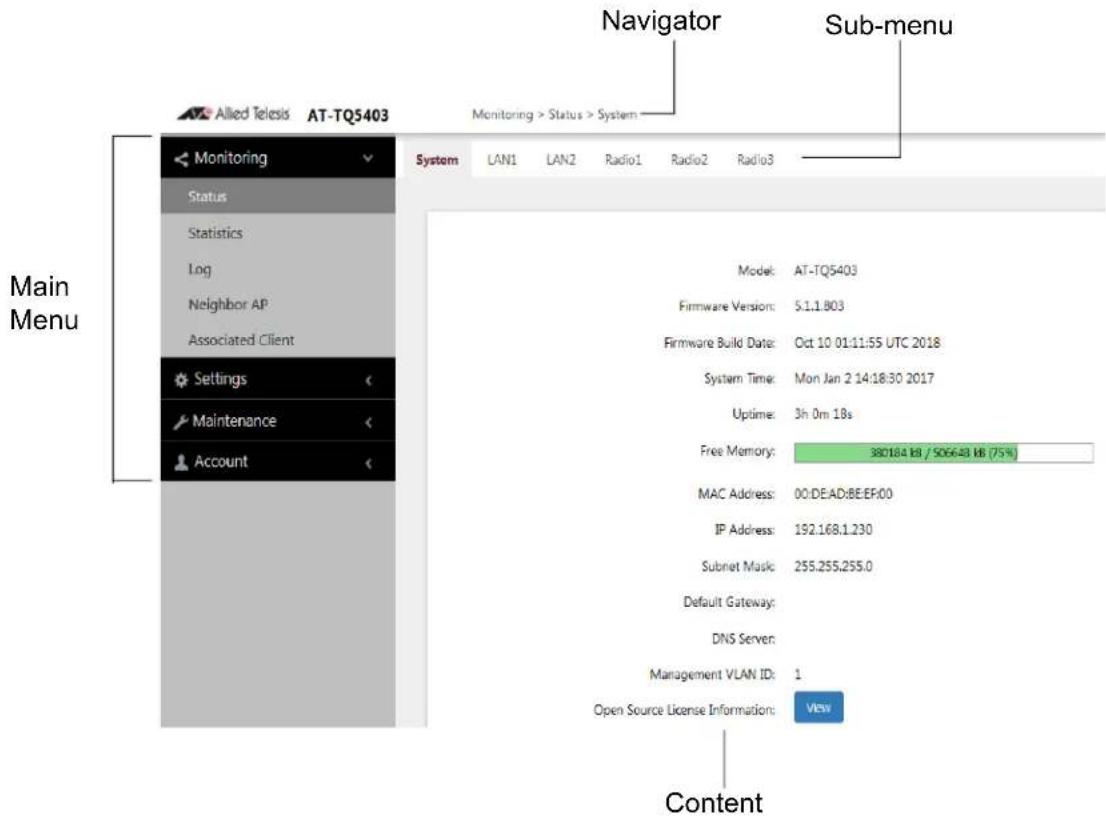
Figure 2. Sample Management Window
Note
The AT-TQ5403e does not have LAN2 on the sub-menu.
Main Menu The main menu is displayed on the left side of the windows and consists of the following selections:
□ Monitoring
□ Settings
□ Maintenance
□ Account
Clicking a main menu option expands it to display the sub-items. The Monitoring option is expanded by default at the start of management sessions.
If the main menu is not displayed, the window might be too small to display the menu and content together. To display the main menu, you can either enlarge the window or click the main menu button, shown in Figure 3. Clicking the main menu button displays the menu over the content window. The menu is hidden again after you make a menu selection.
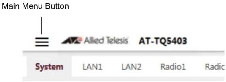
Figure 3. Main Menu Button
Navigation The Navigator shows the menu path of the current window.
Sub-menu Sub-menus are located across the tops of many management windows.
Content This is the main body of the windows. It displays parameters for you to configure or status or statistics information.
Saving and Applying Your Changes
You need to click the SAVE & APPLY button to save and activate your changes when you are finished configuring the parameters in a management window. The button is located in the bottom of the windows. When you click the button, the access point immediately activates your changes and saves them in its configuration file. If you change the parameter settings in a window and navigate to a different window without clicking the button, the access point discards your changes.
The access point displays the following messages when you click the SAVE & APPLY button:
Please wait... waiting for changes to be applied... Changes applied.
Ending Management Sessions
You should always log off when you are finished managing the unit. To log off, select Account > Logout. Click OK at the confirmation prompt. For added security, close your web browser.
What to Configure First
Here are suggestions on what to configure during the first management session:
- Set the country code. Refer to "Setting the Country Code Setting" on page 74.
Note
The country code for units sold in North America, Japan, Canada, Taiwan is preset and cannot be changed.
Note
Changing the country setting disables the radios. The procedure is disruptive to network operations if the unit is actively forwarding client traffic.
-
Change the manager's login name and password. Refer to "Changing the Manager's Login Name and Password" on page 58.
-
If you prefer to use HTTPS management sessions, perform "Configuring the Web Browser Interface" on page 56.
-
Set the language of the management interface to English or Japanese. The default is English. Refer to "Setting the Language of the Web Browser Interface" on page 60.
-
Activate the LAN2 port to double the bandwidth to your wired network. Refer to "Enabling or Disabling the LAN2 Port" on page 126.
Note
Skip Step 5 if you are using the AT-TQ5403e model because it does not have the LAN2 port.
Chapter 1: Getting Started
This chapter contains the following procedures:
☐ “Assigning a Dynamic IP Address from a DHCP Server” on page 34
☐ “Assigning a Static IP Address to the Access Point” on page 37
☐ “Setting the Date and Time with the Network Time Protocol (NTP)” on page 40
☐ “Manually Setting the Date and Time” on page 43
☐ “Configuring SNMPv1 and v2c” on page 45
☐ "Configuring SNMP Traps" on page 49
☐ “Enabling or Disabling the LEDs” on page 51
☐ “Enabling or Disabling the Reset Button” on page 52
Assigning a Dynamic IP Address from a DHCP Server
This section explains how to activate the DHCP client so that the access point receives its IP address from a DHCP server on your network. The unit uses the address to communicate with devices on your network, such as management workstations, syslog servers, and RADIUS servers. The access point can have only one IP address.
If your network does not have a DHCP server or you prefer to manually assign it an IP address, refer to "Assigning a Static IP Address to the Access Point" on page 37.
Note
Changing the IP address of the access point might interrupt your management session. To resume managing the device, start another session using the access point's new IP address.
Note
The default setting for the DHCP client is enabled. You only need to perform this procedure if you disabled the client and assigned the device a static IP address, but now want to reactivate the client.
To configure the access point to receive its IP address from a DHCP server, perform the following procedure:
- Select Settings > System from the main menu.
- Select Network from the sub-menu.
- Select DHCP from the Connection Type pull-down menu. The options in the window change. Refer to Figure 4 on page 35.
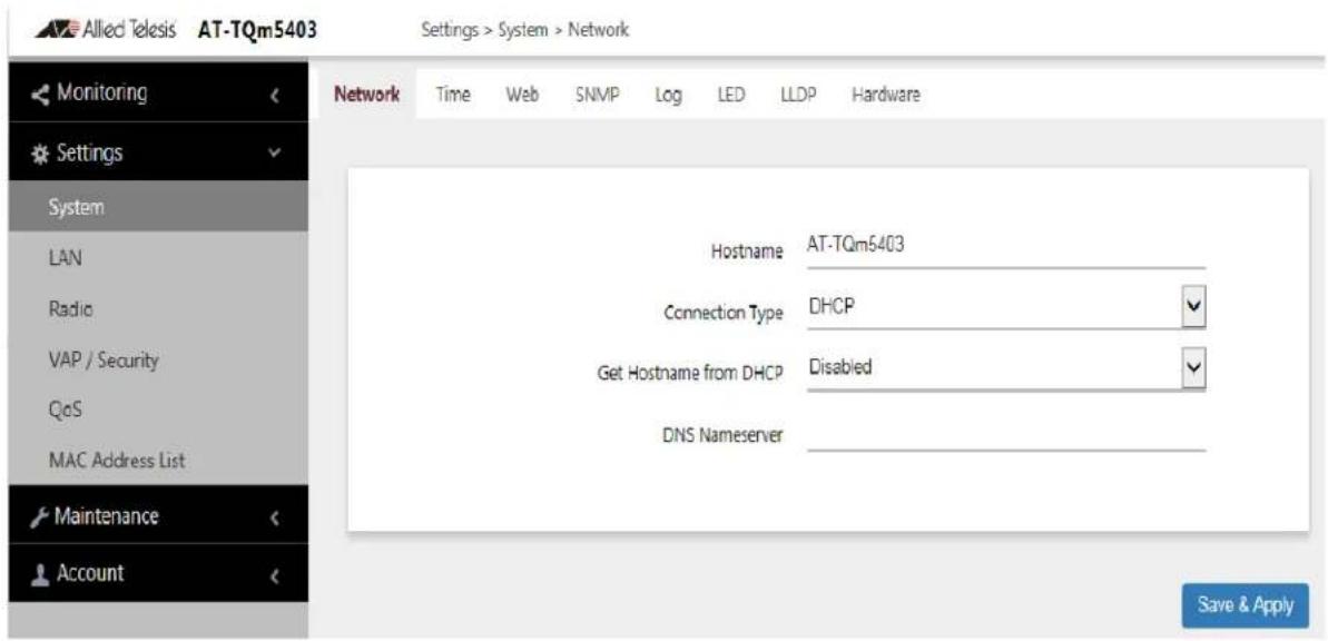
Figure 4. Network DHCP Window
- Configure the fields by referring to Table 2.
Table 2. Network DHCP Window
| Parameter Description | |
| Hostname Enter a host | stname for the access point. Here are the guidelines:- The hostname can be from 1 to 63 alphanumeric characters.- The hostname cannot contain spaces or any special characters, except hyphens.- The first or last character cannot be a hyphen.- The access point can have only one hostname.- The default is AT-TQ5403, AT-TQm5403, or AT-TQ5403e.- If you want the DHCP server to supply the hostname, enable the Get Hostname from DHCP Server option in this window. |
| Connection Type Select | DHCP. This is the default. The Static IP selection is explained in “Assigning a Static IP Address to the Access Point” on page 37. |
| Get Hostname from DHCP Server | Control how the access point obtains its hostname. The options are listed here:- Enabled: The access point queries the DHCP server for its hostname.- Disabled: The access point does not query the DHCP server for a hostname. Instead, it uses the entry in the Hostname field in this window. |
| DNS Name Server Enter the IP address of the DNS name server. If this field is left blank, the access point tries to obtain the address from the DHCP server. The default is no name. | |
- Click the SAVE & APPLY button to save and update the configuration.
Note If the access point stops responding to the web browser management windows, start a new management session using the new IP address that the access point received from the DHCP server.
Assigning a Static IP Address to the Access Point
This section explains how to manually assign an IP address to the access point. The unit uses the address to communicate with devices on your network, such as management workstations, syslog servers, and RADIUS servers. The access point can have only one IP address.
If you prefer the access point obtain its IP configuration from a DHCP server on your network, refer to “Assigning a Dynamic IP Address from a DHCP Server” on page 34.
Note
Changing the IP address of the access point might interrupt your management session. To resume managing the device, start a new session using the access point's new IP address.
To assign a static IP address to the device, perform the following procedure:
- Select Settings > System from the main menu.
- Select Network from the sub-menu.
- Select Static IP from the Connection Type pull-down menu. The options in the window change. Refer to Figure 5.
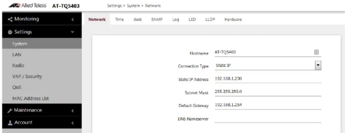
Figure 5. Network Static IP Address Window
- Configure the field values by referring to Table 3 on page 38.
Table 3. Network Static IP Selection Window
| Item Name Description | |
| Host Name Enter a host name for the access point. Here are the guidelines:- The host name can be from 1 to 63 alphanumeric characters.- The hostname cannot contain spaces or any special characters, except hyphens.- The first or last character cannot be a hyphen.- The access point can have only one hostname.- The default is AT-TQ5403, AT-TQm5403, or AT-TQ5403e. | |
| Connection Type Select Static IP. | |
| Static IP Address Enter the new IP address for the access point. The device can have only one IP address. The default is 192.168.1.230. | |
| Subnet Mask Enter the subnet mask for the IP address.The default is 255.255.255.0. | |
| Default Gateway Enter the default gateway address for the unit. The default is 192.168.1.254.The default gateway is an IP address of an interface on a router or other Layer 3 routing device. It specifies the first hop to reaching the subnets or networks where your management devices, such as management workstations and syslog servers, reside. The access point can have only one default gateway and the network portion of the address must be the same as the IP address entered in step 3.You have to assign a default gateway to the access point. If your network does not have a default gateway or you do not want to assign one to the access point at this time, enter an unused IP address of the same network as the IP address. | |
| DNS Name Server Specify the Domain Name Service name server address. This field is optional The default is no name. |
- Click the SAVE & APPLY button to save and update the configuration.
Setting the Date and Time with the Network Time Protocol (NTP)
The access point has a Network Time Protocol (NTP) client for setting its date and time from an SNTP server on your network or the Internet. The access point adds the date and time to log messages and SNMP traps. Here are the guidelines to using the client:
☐ You need to know the host name or IP address of an SNTP server on your network or the Internet. You can specify only one server.
☐ The access point must have an IP address and subnet mask.
☐ The access point must also have a default gateway address if the NTP server is on a different subnet or network. The default gateway must specify the first router hop to the subnet or network of the SNTP server.
☐ The client is compatible with SNTP servers. It is not compatible with NTP servers.
To configure the NTP client, perform the following procedure:
- Select Settings > System from the main menu.
- Select Time from the sub-menu. Refer to Figure 8 on page 43.
- From the Set System Time pull-down menu, select Using Network Time Protocol (NTP). The window is updated with new options. Refer to Figure 6.
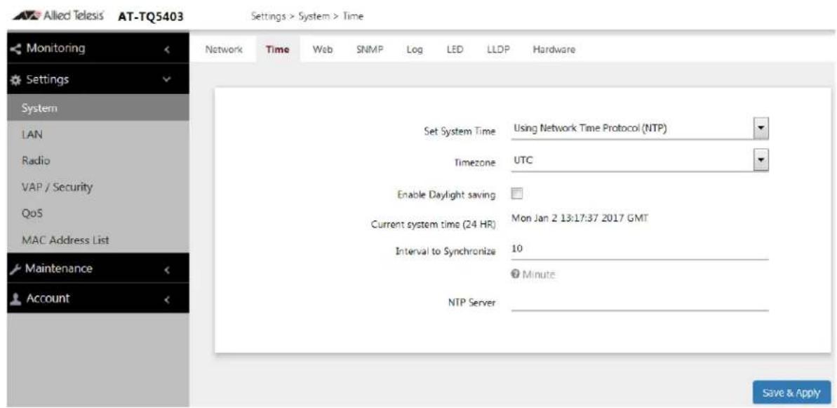
Figure 6. Time Window - NTP Option
4. Configure the fields by referring to Table 4.
Table 4. Time Window - NTP Option
| Item Name Description | |
| Set System Time Select Network time protocol (NTP) to synchronize the date and time of the product with the NTP server. The factory default is Manually. | |
| Timezone Use this pull-down menu to set the time zone of the location of the access point.If the SNTP server is providing Coordinated Universal Time (UTC), the access point uses the time zone parameter to determine its UTC offset, which is the number of hours its location is ahead or behind UTC. It adjusts the time accordingly. | |
| Enable Daylight Saving | If the location of the access point observes daylight savings time, click the check box for this option. The window displays the fields in Figure 7 on page 42.If the area does not observe Daylight Savings time, leave the check box empty. |
| Start Use the pull-down menus to set the date and time for the start of Daylight Savings Time. | |
| End Use the pull-down menus to set the date and time for the end of Daylight Savings Time. | |
| Offset Use the pull-down menu to select the number of minutes to adjust the time at the start and end Daylight Saving Time. The default is 60 minutes. | |
| Current System Time (24 HR) | Displays the date and time of the access point. |
| Interval to Synchronize | Enter the interval in minutes at which the access point synchronizes its time with the SNTP server. The range is 1 to 9999 minutes. The default is 10 minutes. |
| Item Name Description | |
| NTP Server Specify the SNTP server using one of the following methods:- IP address (example, 12.34.56.78)- Fully qualified domain name (FQDN) (example, ntp.mydomain.com)Here are the guidelines:- You can specify only one server.- The first character must be a letter or number.It cannot be a special character.- The last character cannot be a hyphen or period.- The factory default is no server.Observe these guidelines when using an FQDN to identify the server:- It cannot start or end with a hyphen.- Domain labels can have a maximum of 63 characters.- An FQDN can have up to 253 characters. | |
Figure 7 contains the settings for Daylight Savings Time.
![Enable Daylight saving Start Month Week Hour Minute 3 2s Sunday 2 0 End Month Week Hour Minute 11 1s Sunday 2 0 Offset [min] 60](/content/2026/05/798303/images/3e1e3a89f103f9c87cb063f1d44ccf4f736c8b2670fa539456b4920ab97a1110.jpg)
Figure 7. Daylight Savings Time Settings
- Click the SAVE & APPLY button to save and update the configuration.
Manually Setting the Date and Time
This section explains how to manually set the date and time on the access point.
Note
The access point does not have a real-time clock with backed up batteries. Consequently, the date and time, when set manually, are returned to their default values (Jan 1 00: 00: 00 2018) when the device is reset or powered off.
Note
Allied Telesis recommends using a SNTP server to set the date and time. For instructions, refer to “Setting the Date and Time with the Network Time Protocol (NTP)” on page 40.
To manually set the date and time, perform the following procedure:
- Select Settings > System from the main menu.
- Select Time from the sub-menu. Refer to Figure 8.
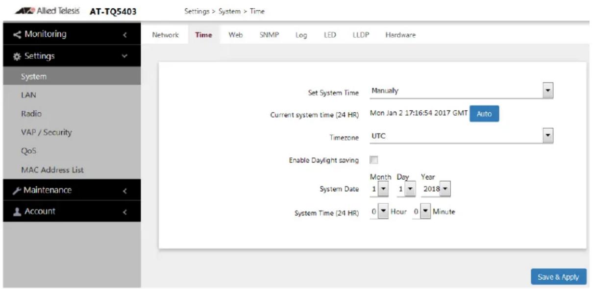
Figure 8. Time Window - Manually Option
- Configure the parameters by referring to Table 5 on page 44.
Table 5. Time Window - Manually Option
| Field Description | |
| Set System Time Select Manually. This is the default. | |
| Current System Time (24 HR) | Displays the current date and time settings.Click the AUTO button to set the date and time on the access point according to your management workstation. |
| Timezone Select the Time Zone of the access point from the pull-down menu. | |
| Enable Daylight Savings | If the location of the access point observes daylight savings time, click the dialog box for the Adjust Time for Daylight Savings parameter. The window displays the fields in Figure 7 on page 42If the area does not observe Daylight Savings time, leave the check box empty. |
| Start Use the pull-down menus to set the date and time for the start of Daylight Savings Time. | |
| End Use the pull-down menus to set the date and time for the end of Daylight Savings Time. | |
| Offset Use the pull-down menu to select the number of minutes to adjust the time at the start and end Daylight Saving Time. The default is 60 minutes. | |
| System Date Use the pull-down menus to set the current month, day, and year. | |
| System Time Use the pull-down menus to set the current hours and minutes. The hours are in 24 hours. For example, 14 represent 2:00 p.m. | |
- Click the SAVE & APPLY button to save and update the configuration.
You can use SNMPv1 and v2c to view the settings and client statistics on the access point, and receive traps. Here are the guidelines:
☐ You cannot use SNMP to change the settings on the access point.
☐ The access point does not support SNMPv3.
☐ The access point has one read-only community string.
☐ The unit must have an IP address for SNMP management. For instructions, refer to “Assigning a Static IP Address to the Access Point” on page 37 or “Assigning a Dynamic IP Address from a DHCP Server” on page 34.
To enable or disable SNMP, perform the following procedure:
- Select Settings > System from the main menu.
- Select SNMP from the sub-menu.
- Click the Agent Settings tab. This is the default tab. Refer to Figure 9.
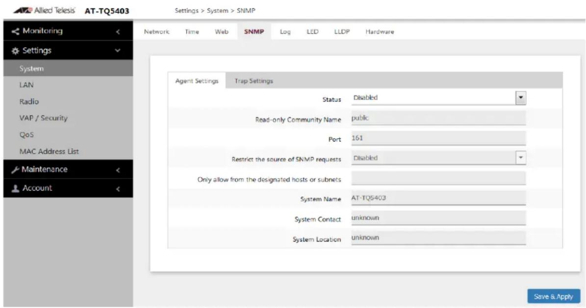
Figure 9. SNMP Agent Settings Window
- Configure the fields by referring to Table 6 on page 46.
Note
To configure the parameters in the window, you must first set the Status parameter to Enabled. You cannot adjust the settings when Status is Disabled.
Table 6. SNMP Agent Settings Window
| Field Description | |
| Status Use this option to activate or deactivate the SNMP agent on the access point. The options are explained here:- Enabled: Select this option to activate the SNMP agent and trap settings. This allows you to use SNMP to view the parameter settings on the access point. It also allows the access point to send traps. You have to enable SNMP to configure the settings in this window and the Trap Settings window.- Disabled: Select this option to disable SNMP and the trap settings. This is the default setting. | |
| Read-only Community Name | Use this option to specify the read-only community string for the access point. The community string is used to view the MIB settings of the device. Here are the guidelines:- The community string can be from 1 to 256 alphanumeric characters.- The community string cannot contain any spaces.- The community string is case sensitive.- You can specify only one read-only community string.- You can not leave the field empty.- The default read-only community string is “public”.- The community string cannot contain any of the following symbols: "" (Double quote), " (single quote), '¥' or '/' (Yen sign or backslash), '&', '<', '>''. |
| Port Use this parameter to specify the port number for SNMP. The range is 1 to 65535. The default is 161. | |
| Restrict the Source of SNMP Requests | Use this option to increase the security of the access point by restricting the use of SNMP to specific subnets or individual workstations. The options are described here:- Enabled: Check this option to restrict the use of SNMP on the access point to only those management stations specified in the next field in the window.- Disabled: Check this option to disable this feature and permit any workstation to use the community string to view the unit. This is the default setting. |
| Only allow from the designated hosts or subnets | Use this field to identify the management workstations permitted to use SNMP to view the device. This field only applies if you select the Enabled option in the previous field. Here are the guidelines:- You can specify only one value in the field.- You can specify a specific workstation by its IP address (for example,149.23.45.102).- You can specify a subnet by including the subnet mask (for example, 67.101.4.0/24).- You can specify a workstation by its FQDN.- The default is blank.Observe these guidelines when using an FQDN to identify the workstation:- It cannot start or end with a hyphen.- Domain labels can have a maximum of 63 characters.- An FQDN can have up to 253 characters. |
| System Name | Specify the SNMP system name of the access point. The default is AT-TQ5403, AT-TQm5403, or AT-TQ5403e. |
| System Contact | Specify the system administrator name. The system contact can be up to 64 alphanumeric characters. The default is Unknown. |
| System Location | Enter the location of the device. It can be up to 64 alphanumeric characters. The default is Unknown. |
- Click the SAVE & APPLY button to save and update the configuration.
Configuring SNMP Traps
To configure the access point to transmit SNMP traps, perform the following procedure:
- Select Settings > System from the main menu.
- Select SNMP from the sub-menu.
- Click the Trap Settings tab. Refer to Figure 10.
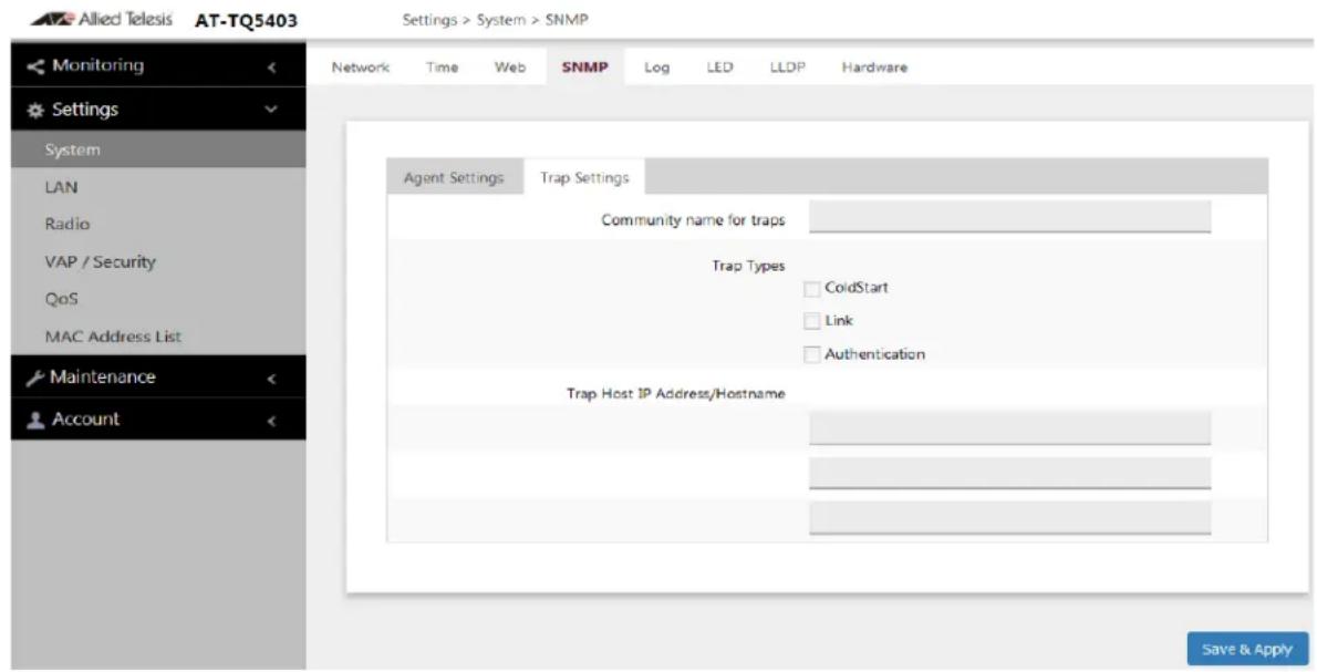
Figure 10. Trap Settings Window
Note
The Status parameter has to be set to Enabled in the Agent Settings tab before you can configure the parameters in this window. Refer to "Configuring SNMPv1 and v2c" on page 45.
- Configure the fields by referring to Table 7 on page 50.
Table 7. SNMP Trap Settings Window
| Parameter Description | |
| Community Name for Traps | Use this field to specify the community name the access point is to use to transmit traps. Here are the guidelines:- The community name can be from 1 to 256 alphanumeric characters.- The default is blank.- The name cannot contain any of the following characters: "" (Double quote), " (single quote), '¥' or '/' (Yen sign or backslash), '&', '<', '>.' |
| Trap Types Select radio button for the trap type you want to generate:- Cold Start - This trap is sent when the SNMP agent started.- Link - This trap is sent when a radio enabled or disabled.- Authentication - This trap is sent when an SNMP authentication fails | |
| Trap Host IP Address / Hostname | Specify the SNMP hosts to receive the traps. Here are the guidelines:- You can specify up to three hosts.- The hosts can be identified by IP addresses or hostnames.- The default is blank.Observe these guidelines when using an FQDN to identify a host:- It cannot start or end with a hyphen.- Domain labels can have a maximum of 63 characters.- An FQDN can have up to 253 characters. |
- Click the SAVE & APPLY button to save and update the configuration.
Enabling or Disabling the LEDs
The access point has an Eco Mode. When activated, it turns off the LEDs on the top panel. You might activate the mode when you are not using the LEDS to monitor or troubleshoot the device. The default setting for the LEDs is on.
To turn the LEDs on or off, perform the following procedure:
- Select Settings > System in the main menu.
- Select LED in the sub-menu. Refer to Figure 11.
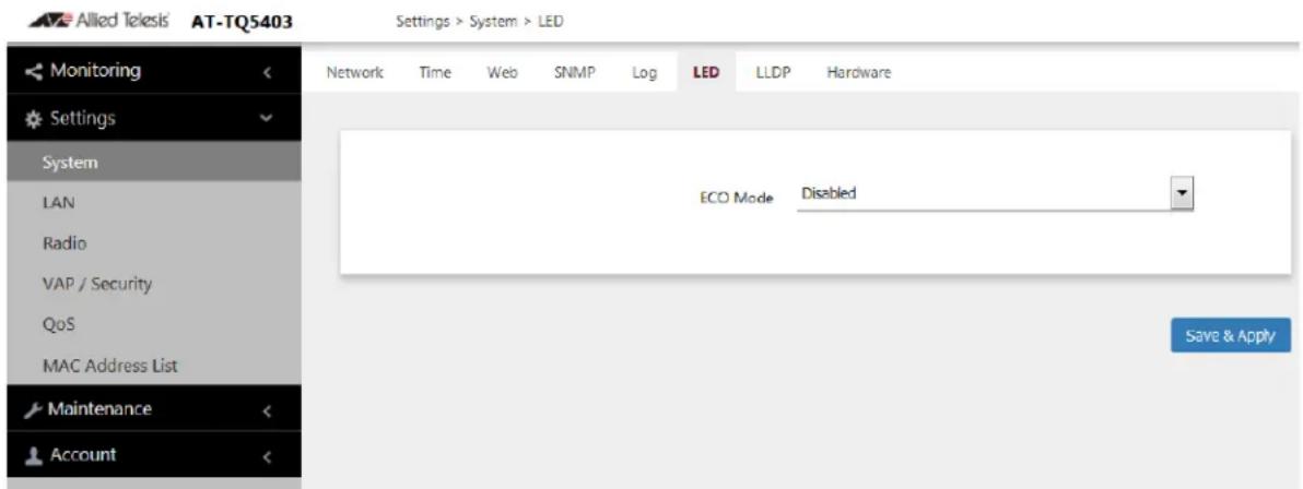
Figure 11. LED Window
- From the Eco Mode pull-down menu, select one of the following:
☐ Enabled: The Eco Mode is enabled. The LEDs are off.
□ Disabled: The Eco Mode is disabled. The LEDs are on. This is the default setting.
- Click the Save & Apply button to save and update the configuration.
Enabling or Disabling the Reset Button
This section explains how to enable or disable the Reset button on the rear panel of the access point. You use the Reset button to restore the default settings to the device.
The default setting for each model is shown in Table 8.
Table 8. Default Settings for Reset Button
| Model Default Setting for Reset Button | |
| AT-TQ5403 Enabled | |
| AT-TQm5403 Enabled | |
| AT-TQ5403e Disabled |
If the unit is installed in a non-secure area, you might disable the button to prevent unauthorized individuals from pressing it and disrupting the operations of your wireless network.
Note
If you disable the Reset button, be sure not to forget the manager account password. Otherwise, you will not be able to manage the unit with the web browser interface.
To enable or disable the Reset button, perform the following procedure:
- Select Settings > System from the main menu.
- Select Hardware from the sub-menu. Refer to Figure 12.
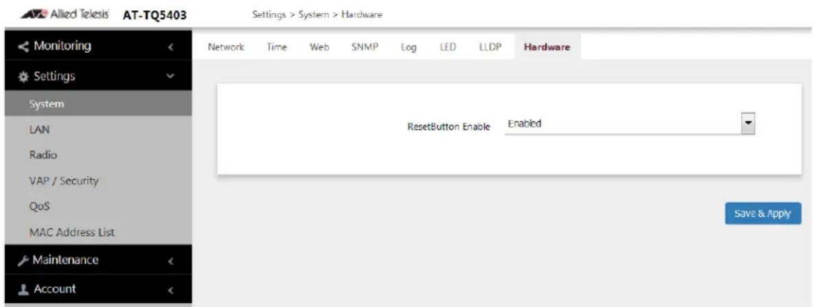
Figure 12. Hardware Window
- Configure the fields by referring to Table 7 on page 50:
☐ Enabled: The Reset button is enabled.
□ Disabled: The Reset button is disabled.
- Click the SAVE & APPLY button to save and update the configuration.
Chapter 2: Basic Settings
Chapter 3
Web Browser Interface
This chapter contains the following procedures:
☐ “Configuring the Web Browser Interface” on page 56
- “Changing the Manager’s Login Name and Password” on page 58
☐ “Setting the Language of the Web Browser Interface” on page 60
Configuring the Web Browser Interface
This section has the following management functions:
☐ Specify the maximum number of administrators that can manage the access point at one time with the web browser interface.
☐ Specify the time interval after which the access point automatically ends inactive management sessions.
□ Enable or disable HTTP or HTTPS web management.
□ Generate a self-signed HTTPS certificate.
Note
Do not disable both HTTP and HTTPS. Otherwise, you will not be able to manage the access point with a web browser.
Note
HTTP management is non-secure, meaning the packets exchanged between the access point and your workstation are sent in clear text, leaving them vulnerable to snooping. For this reason, Allied Telesis recommends using HTTPS to manage the access point.
To configure the above functions, perform the following procedure:
- Select Settings > System from the main menu.
- Select Web from the sub-menu. Refer to Figure 13.
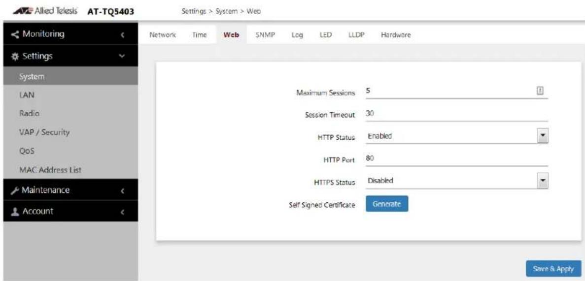
Figure 13. Web Window
- Configure the fields by referring to Table 9.
Table 9. Web Window
| Field Description | |
| Maximum Sessions | Specify the maximum number of active management sessions the access point will support at one time. Here are the guidelines:- The range is 1 to 10 sessions.- The number of sessions is the sum of HTTP and HTTPS connections.- The default is five sessions.- The access point blocks new management session after reaching the maximum number of sessions. |
| Session Timeout | Specify the time interval in minutes after which the access point automatically ends inactive sessions. The range is 1 to 1440 minutes (1440 minutes = 1 day). The default is five minutes. |
| HTTP Status Enable or | disable HTTP management. The default is enabled. |
| HTTP Port Specify the | port number of the HTTP server.The range is 0 to 65535. The default is 80. |
| HTTPS Status Enable | or disable HTTPS management. The default is disabled. The HTTPS server uses port 443. It cannot be changed. |
| Self Signed Certificate | Generate a self-signed certificate for HTTPS management. The access point comes with a certificate, but you can generate a new one with this option. The new certificate automatically replaces the old certificate. |
- Click the SAVE & APPLY button to save and update the configuration.
Note
If you disabled the HTTP or HTTPS mode you are currently using to manage the device, the access point ends your management session. To resume managing the device, start a new session using the other mode.
Changing the Manager's Login Name and Password
This procedure explains how to change the login name and password of the manager account on the access point. The default values are “manager” and “friend”, respectively. The access point has only one manager account.
Changing the name and password does not affect your current management session.
Note
Allied Telesis strongly recommends changing the factory default password during the first management session to protect the device from unauthorized access.
To change the login name and password of the manager account, perform the following procedure:
- Select Account > User from the main menu, Refer to Figure 14.
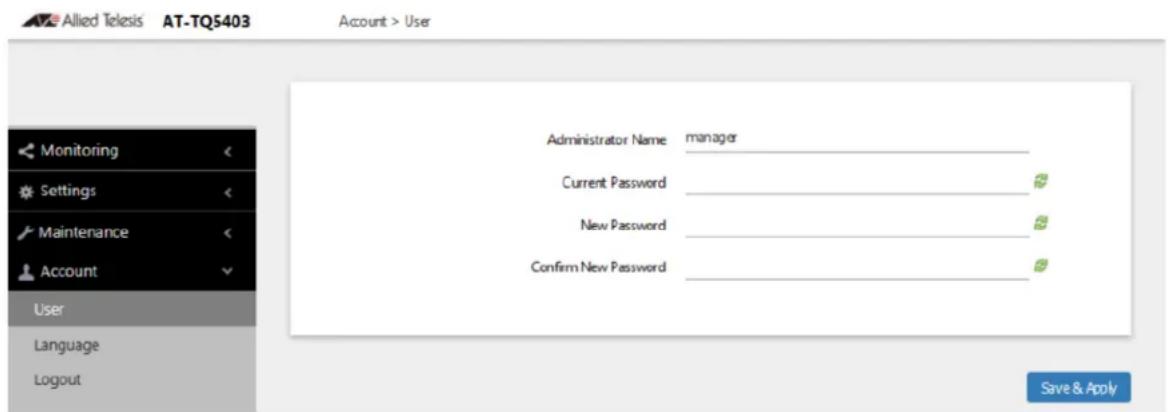
Figure 14. User Window
- To change the manager name, select the Administrator Name field and enter a new name. Here are the guidelines:
☐ The name can be up to 12 alphanumeric characters.
☐ The first character must be a letter. It cannot be a number or special character.
☐ The name is case-sensitive.
☐ The default name is "manager".
- To change the password, select the Current Password field and enter the account's current password. The default is "friend".
To display the password as alphanumeric characters or asterisks, click the green, double arrow symbol.
- Select the New Password field and enter a new password. The new password. Here are the guidelines:
☐ The password can be up to 32 alphanumeric characters.
☐ It can not contain spaces or any of these special characters: ", \$, :, <, >, ', &, *.
□ It is case-sensitive.
-
Select the Confirm New Password field and enter the new password again.
-
Click the SAVE & APPLY button to save and update the configuration. You must use the new manager name and password in all future management sessions.
Setting the Language of the Web Browser Interface
The access point can display the web browser interface in either English or Japanese. The default is English. To set the language, perform the following procedure:
- Select Account > Language from the main menu. Refer to Figure 15.
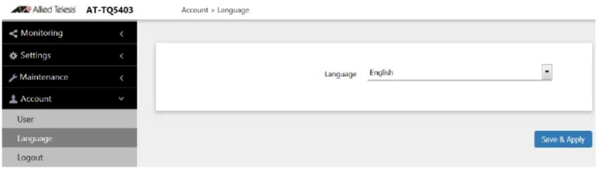
Figure 15. Language Window
- From the Language pull-down menu, select one of the following:
□ English
□ Japanese
- Click the SAVE & APPLY button to save and update the configuration. The management interface changes to the designated language.
This chapter has the following procedures:
☐ "Configuring the Radios" on page 62
☐ "Displaying Radio Status" on page 71
☐ “Dynamic Frequency Selection” on page 73
☐ "Setting the Country Code Setting" on page 74
☐ "Selecting the Location" on page 75
Configuring the Radios
The radio settings are divided into two groups:
☐ "Configuring Basic Radio Settings" next
☐ "Configuring Advanced Radio Settings" on page 66
Configuring Basic Radio Settings
To configure the basic settings for Radio1, Radio2, or Radio3, perform the following procedure:
- Select Settings > Radio.
- Select Radio1, Radio2, or Radio3 from the sub-menu. You can configure only one radio at a time.
- Click the Basic Settings tab. This is the default tab.
The AT-TQ5403 and AT-TQm5403 access points display a window shown in Figure 16. The AT-TQ5403e access point displays a window shown in Figure 17 on page 63.
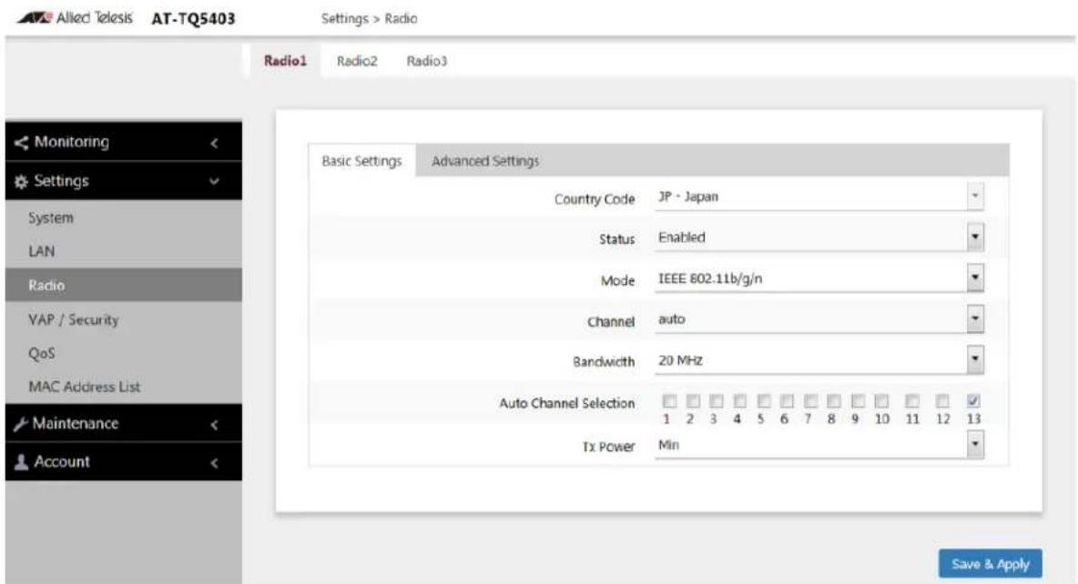
Figure 16. Basic Radio Settings Window on AT-TQ5403 and AT-TQm5403
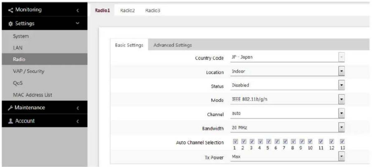
Figure 17. Basic Radio Settings Window on AT-TQ5403e
- Configure the settings by referring to Table 10.
Table 10. Basic Radio Settings Window
| Field Description |
| Country Code Select the country code that applies to your country or region. The country code ensures that the device operates in compliance with the codes and regulations of your region or country.Here are the guidelines:- You can select only one country.- The Country Code parameter is shown in the Basic Settings windows of all three radios but it can only be set from Radio1.- The same country code applies to all three radios.- Changing the country code disables the radios.- You have to reconfigure the radio settings if you change the country code.- You cannot change the country code on units sold in North America, Japan, Canada, or Taiwan. |
Table 10. Basic Radio Settings Window (Continued)
| Field Description | |
| Location(AT-TQ5403e Only) | Select a location where the AT-TQ5403e access point is installed.The selections are:- Indoor: This is the default setting.- OutdoorFor more information, see “Selecting the Location” on page 75. |
| Status Activate or | deactivate the radio. The selections in the pull-down menu are described here:- Enabled: Activates the radio.- Disabled: Deactivates the radio. This is the default setting. |
| Mode (Radio1) | Select the communications protocol for Radio1 from the pull-down menu. The selections are listed here:- IEEE 802.11b/g: The access point accepts only 802.11b or 802.11g clients.- IEEE 802.11b/g/n: The access point accepts 802.11b, 802.11g, or 802.11n clients operating at 2.4GHz. This is the default for Radio1. |
| Mode (Radio2 or Radio3) | Select the communications protocol for Radio2 or Radio3 from the pull-down menu. The selections are listed here:- IEEE 802.11a: The access point accepts 802.11a clients.- IEEE 802.11a/n/ac: The access point accepts 802.11a, 802.11n, and 802.11ac clients operating. This is the default setting for Radio2 and Radio3.Wi-Fi multimedia (WMM) has to be enabled (default) to use IEEE 802.11n or IEEE 802.11ac.Refer to “Configuring QoS Basic Settings” on page 116. |
| Channel Select the channel for the radio from the pull-down menu. Here are the guidelines:- You can select only one channel.- The channels vary by radio, bandwidth, and country.- Select "auto", the default setting, to have the radio select the channel automatically. The access point scans the available channels on the radio and selects the one with the least interference.- If you select Auto, you can use the Auto Channel Selection parameter in this window to restrict the channels from which the access point can choose.- You must set the channel manually when using the Wireless Distribution System (WDS) bridge feature. For information, refer to “WDS Bridge Elements” on page 137.- To view the current active channel, refer to “Displaying Radio Status” on page 71. | |
| Bandwidth (Radio1) | Select the bandwidth for Radio1 from the pull-down menu. The selections for IEEE 802.11n are listed here:- 20 MHz. This is the default setting.- 40 MHzFor IEEE 802.11n modes, channel width can be 40 MHz-wide or the legacy 20 MHz-wide. The 40 MHz-wide channel allows for higher data rates, but reduces the number of available channels for other wireless devices.The only bandwidth for IEEE 802.11b/g is 20 MHz. |
| Bandwidth (Radio2 or Radio3) | Select the bandwidth for Radio2 or Radio3 from the pull-down menu. The available bandwidths for IEEE 802.11n/ac are listed here:- 20 MHz. This is the default setting.- 40 MHz- 80 MHzThe only bandwidth for IEEE 802.11a is 20 MHz. |
| Auto Channel Selection | Select the channels that the radio can chose from when the Channel parameter is set to Auto. Here are the guidelines.- A channel is enabled when its check box has a check and disabled when the check box is empty.- The available channels vary by radio, mode, bandwidth, and country.- The default is all available channels are enabled.- This parameter is disabled when the channel is selected manually. |
| Tx Power Select the strength of the radio transmitter. The selections are Max (maximum), High, Middle, Low, Min (minimum). The default is Max. | |
- Click the SAVE & APPLY button to save and update the configuration.
Configuring Advanced Radio Settings
To configure the advanced parameters for Radio1, Radio2, or Radio3, perform the following procedure:
- Select Settings > Radio from the main menu.
- Select Radio1, Radio2, or Radio3 from the sub-menu. You can configure only one radio at a time.
- Click the Advanced Settings tab. Refer to Figure 18.
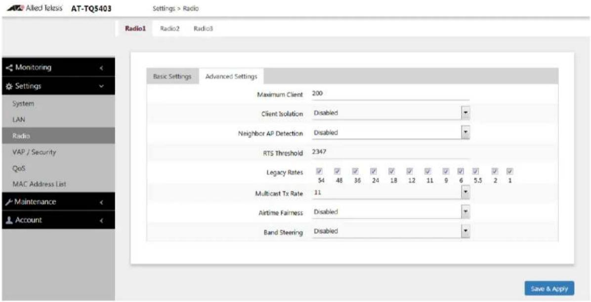
Figure 18. Advanced Radio Settings Window
- Configure the parameters by referring to Table 11.
Table 11. Advanced Radio Settings Window
| Field Description | |
| Maximum Clients | Use this option to specify the maximum number of wireless clients that a radio will support at one time. You might use the option to control the distribution of clients over the radios. The guidelines are given here:- The range is 0 to 200 clients. The default is 200 clients.- The AT-TQ5403 access point can support a maximum of 200 clients on all radios at one time.- The AT-TQm5403 access point can support a maximum of 127 clients on all radios at one time.- The AT-TQ5403e access point can support a maximum of 200 clients on all radios at one time. |
| Maximum Clients (continued) | - A radio rejects all clients when the parameter is set to 0.In the following example for the AT-TQ5403 access point, Radio1 is limited to a maximum of 50 clients while Radio2 and Radio3 are permitted up to 75 clients each:- 2.4GHz Radio1 - 50 clients- 5GHz Radio2 - 75 clients- 5GHz Radio3 - 75 clients |
| Client Isolation Use this option to enable or disable client isolation. When the feature is enabled, the access point does not allow clients in the same VAP to communicate with each other. However, they can communicate with the wired LAN port and with clients in other VAPs.The feature is typically used to enhance wireless security. For instance, by activating this feature on a publicly accessible access point, you enable clients to communicate with the wired LAN port, but not with each other.The options are listed here:- Enabled: Activates station isolation. The access point does not allow wireless clients of the same VAP to communicate with each other.- Disabled: Deactivates client isolation. The access point allows wireless clients to communicate with other clients in the same VAP or different VAPs, and with the wired LAN. This is the default setting.This feature does not apply to WDS. Refer to “Introduction to Wireless Distribution Bridges” on page 134. | |
| Neighbor AP Detection | Use this option to control whether the access point listens for neighboring access points. Here are the options:- Enabled: The access point listens for neighboring access points and displays them in the Neighbor AP window. Refer to “Displaying Neighboring Access Points” on page 147.- Disabled: The access point does not listen for neighboring access points. This is the default setting. |
| RTS Threshold | Specifies the size in octets of MPDUs that initiate a Request to Send (RTS) and Clear to Send (CTS) handshake, in IEEE 802.11b/g. The range is 0 to 2347 octets. The default is 2347 octets.You can use this parameter to control the use of RTS/CTS handshakes when the access point transmits MPDUs. The access point uses the handshake before transmitting MPDUs that exceed the defined threshold. If you specify a low value, RTS packets are sent more frequently, which may consume more bandwidth and reduce the throughput. But more RTS packets may help a network recover from interference or collisions, which might occur on a busy network. |
| Legacy Rates Select | Select the supported and advertised data transmission rates for IEEE 802.11b/g of the radio. Here are the guidelines:- The data rates vary by country.- The default is all data rates are enabled.- Radios are generally more efficient when they advertise subsets of their supported data rates. |
| Multicast Tx Rate | Select the maximum amount of multicast packets the radio can transmit per second. The default values are listed here:- 2.4GHz Radio1: 11Mbps- 5GHz Radio2: 6Mbps- 5GHz Radio3: 6Mbps |
| Airtime Fairness | Select Enabled to activate airtime fairness to provide the same communication time (air time) to all connected clients regardless of communication speed. Select Disabled, the default, to turn Airtime Fairness off. |
| Band Steering Use | this option to enable or disable band steering on the radios. Band steering reduces radio congestion by forcing wireless clients that support both 2.4GHz and 5GHz radios to associate with VAPs on a different radio during periods of traffic congestion. Band steering forces clients to associate with VAPs on a 5GHz radio when there is traffic congestion on the 2.4GHz radio. Conversely, clients are forced to associate with VAPs on the 2.4GHz radio when the 5GHz radios are congested. Here are the guidelines:- Enabling band steering on one radio activates it on all three radios. Conversely, disabling the feature on one radio disables it on all radios.- Ideally, the VAP settings on all radios should be identical. This includes SSID names, VLAN IDs, and security settings.- The default setting is disabled. |
- Click the SAVE & APPLY button to save and update the configuration.
Displaying Radio Status
To display operational information about a radio, perform the following procedure:
- Select Monitoring > Status from the main menu.
- Select Radio1, Radio2, or Radio3 from the sub-menu. You can view only one radio at a time. The example in Figure 19 is for Radio1.
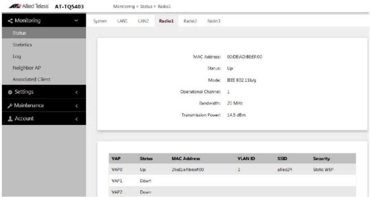
Figure 19. Radio Status Window
Note
The radio status windows for Radio2 and Radio3 include a DFS (Dynamic Frequency Selection) field. For information, refer to "Dynamic Frequency Selection" on page 73.
The fields are defined in Table 12.
Table 12. Radio Status Window
| Field Description | |
| MAC Address | Displays the MAC address of the wireless interface. |
| Status Displays | the status (up, down) of the wireless interface. |
| Mode Displays | the current wireless communication mode. Radio1 has these modes:- IEEE 802.11b/g- IEEE 802.11b/g/nRadio2 and Radio3 have these modes- IEEE 802.11a- IEEE 802.11a/n/ac |
| Operational Channel | Displays the active channel. The channel may have been selected manually or automatically. |
| Bandwidth Displays the current bandwidth. | |
| Transmission Power | Displays the transmission power, in dBm. |
| DFS(Radio2 and Radio3 only) | Displays the status of DFS (Dynamic Frequency Selection). For background information, refer to “Dynamic Frequency Selection” on page 73. The possible states are listed here:- IDLE: DFS is inactive because the radio is using a W52 or W58 channel. Those channels are not used by DFS.- CAC: Channel Availability Check: The radio has selected a W53 or W56 channel and is performing the DFS radar detection period for one minute before beginning to transmit or receive wireless traffic. If no radar is detected, the radio moves to the ISM status.- ISM: In-Service Monitoring: The radio is using a DFS target channel. If radar is detected, it changes the channel. The DFS status changes to IDLE if the new channel is W52 or W58, or to CAC if the new channel is W53 or W56.- OOC: Out Of Channels: The radio has stopped transmitting and receiving client packets because radar signals are detected on all channel candidates. After 30 minutes, it transitions to CAC. |
Dynamic Frequency Selection
Dynamic frequency selection (DFS) is an industry standard that defines how wireless access points are to respond to the presence of radar signals on 5GHz channels. The standard states that a wireless access point that detects radar signals on its current 5GHz channel has to stop transmitting and select another channel to avoid interfering with the signals.
The wireless access points support DFS on 5GHz channels that countries or regions have designated as DFS channels. If an access point detects a radar signal on its current 5GHz channel and if the channel is designated as a DFS channel, it immediately marks the channel as unusable for a minimum of thirty minutes and randomly selects another channel with which to communicate with its clients.
If a wireless access point is using a DFS 5GHz channel for a WDS bridge and it detects radar signals, it randomly selects another channel so as not to interfere with the signals. This action, however, renders the bridge non-functional. For background information, refer to “Introduction to Wireless Distribution Bridges” on page 134.
You can prevent this from occurring by selecting a non-DFS 5GHz channel as the communication link between the wireless access points of a WDS bridge. Here are three examples of non-DFS channels:
□ 36 - 5180 MHz
□ 40 - 5200 MHz
□ 44 - 5220 MHz
Here are the guidelines for DFS on the wireless access points:
☐ DFS channels vary by country or region.
☐ DFS cannot be disabled on the wireless access points.
☐ DFS does not apply to channels on the 2.4GHz radio.
Note
To determine whether Radio2 and Radio3 are using DFS channels, refer to "Displaying Radio Status" on page 71.
Setting the Country Code Setting
You should set the country code setting of the access point as soon as you install the unit so that it operates in compliance with the codes and regulations of your region or country.
Note
Changing the country setting disables the radios. The procedure is disruptive to the operations of your network if the unit is actively forwarding network traffic.
To set the country code setting, perform the following procedure:
- Select Settings > Radio.
- Select Radio1 from the sub-menu. The country code must be set from Radio1.
-
Click the Basic Settings tab. This is the default tab. Refer to Figure 16 on page 62.
-
Select the Country Code pull-down menu and choose your country or region. Here are the guidelines:
☐ You can select only one country.
☐ The Country Code parameter is shown in the Basic Settings windows of all three radios, but can only be set from Radio1.
☐ The same country code applies to all three radios.
□ Changing the country code disables the radios.
☐ You have to reconfigure the radio settings after changing this parameter.
- Click the SAVE & APPLY button to save and update the configuration.
Selecting the Location
When your AT-TQ5403e access point is used outdoors, select the Outdoor option in the Location parameter.
Note
The location parameter is available only for the AT-TQ5403e access point.
Guidelines to Changing the Location
Here are the guidelines to changing the location:
☐ The location parameter is shown in the Basic Settings windows of all three radios but it can only be set from Radio1.
☐ The same location applies to all three radios.
☐ The default setting is "Indoor."
☐ When you use AT-TQ5403e access point in a country that has outdoor channel restrictions and select the Outdoor option in the location parameter, the radio will be disabled.

Warning
Regulatory restrictions prohibit the use of the following frequencies on the 5GHz radio on the AT-TQ5403e access point when the unit is deployed outdoors. The restrictions do not apply when the unit is installed indoors:
European Community (CE mark): 5180 to 5240MHz (channels 36 to 48) and 5260 to 5320MHz (channels 52 to 64)
Japan (TELEC mark): 5180 to 5240MHz (channels 36 to 48) and 5260 to 5320MHz (channels 52 to 64)
Australia and New Zealand (RCM): 5180 to 5240MHz (channels 36 to 48) and 5250 to 5350MHz (channels 52 to 64)
Russia (EAC mark): 5150 to 5250MHz (channels 36 to 48) and 5250 to 5350MHz (channels 52 to 64)
Canada (IC mark): 5180 to 5240MHz (channels 36 to 48)
Brazil (ANATEL mark):5150 to 5250MHz (channels 36 to 48)
Mexico (NOM mark): 2412 to 2447MHz (channels 1 to 8)
Changing the Location to Outdoor
To change the location to the Outdoor option, perform the following procedure:
- Select Settings > Radio.
- Select Radio1 from the sub-menu. The location must be set from Radio1.
- Click the Basic Settings tab. This is the default tab. See Figure 17 on page 63.
- Select the Location pull-down menu and choose the Outdoor option.
The access point displays the prompt "Do you want to use this AP outdoors? If yes, in case no legal outdoor channel for a radio, this radio will be disabled. Are you sure?"
-
Click OK or Cancel.
-
Click the SAVE & APPLY button to save and update the configuration.
Changing the Location to Indoor
To change the location to the Outdoor option, perform the following procedure:
- Select Settings > Radio.
- Select Radio1 from the sub-menu. The location must be set from Radio1.
- Click the Basic Settings tab. This is the default tab. See Figure 17 on page 63.
- Select the Location pull-down menu and choose the Indoor option.
- Click the SAVE & APPLY button to save and update the configuration.
Chapter 5
Virtual Access Points
This chapter contains the procedures for managing virtual access points (VAPs). The chapter contains the following sections:
☐ "VAP Introduction" on page 78
☐ “Configuring Basic VAP Parameters” on page 79
☐ "Configuring Captive Portal" on page 84
☐ "Configuring VAP Security" on page 94
☐ “Configuring VAP Fast Roaming” on page 104
☐ "Configuring the MAC Address List" on page 106
☐ “Displaying VAP and LAN Ports Statistics” on page 108
☐ “Advanced Settings” on page 110
VAP Introduction
Virtual access points (VAPs) are independent broadcast domains that function as the wireless equivalent of Ethernet VLANs. They are seen by clients as independent access points, with their own VIDs, SSIDs, and security methods. Here are VAP guidelines:
☐ Each radio can have up to eight VAPs. Allied Telesis recommends no more than five VAPs per radio for best performance.
☐ The VAPs are numbered from 0 to 7.
☐ You can enable or disable the VAPs individually, except for VAP0, which can only be disabled by disabling its radio.
☐ The VAP securities are static WEP, Enterprise WPA, and Personal WPA.
☐ The VAPs of a radio can have different security methods.
☐ VAPs can have the same or different VLAN IDs.
VAP parameters are divided into these three groups:
☐ "Configuring Basic VAP Parameters" on page 79
☐ "Configuring VAP Security" on page 94
☐ “Configuring VAP Fast Roaming” on page 104
Configuring Basic VAP Parameters
To configure basic VAP settings, perform the following procedure:
- Select Settings > VAP / Security from the main menu.
- Select Radio1, Radio2, or Radio3 from the sub-menu. The default is Radio1. You can configure only one radio at a time.
- Select a VAP to configure from the next sub-menu. The default is VAP0. You can configure only one VAP at a time.
- Select the Virtual Access Point tab. This is the default tab. The example in Figure 20 shows the settings for VAP0 on Radio1.
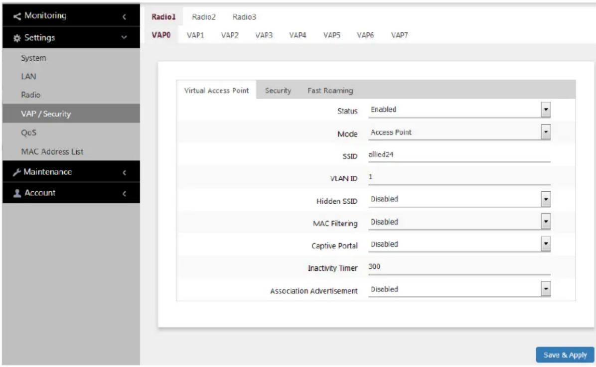
Figure 20. Virtual Access Point Tab
- Configure the parameters by referring to Table 13 on page 80.
Table 13. Virtual Access Point Tab
| Field Description | |
| Status Enable or | disable the VAP. Here are the guidelines.- A disabled VAP does not forward any ingress or egress traffic.- The default setting for VAP0 is enabled.- The default setting for VAP1 to VAP7 is disabled.- You cannot disable VAP0. To stop VAP0 from forwarding traffic from wireless clients, you have to disable its radio. |
| Mode Select a mode setting from the pull-down menu. This parameter applies only to VAP0. The menu choices are listed here:- Access Point: Select this mode to have a VAP function as a normal VAP, without WDS bridging. This is the default setting.- WDS Parent: Select this mode to have VAP0 function as the parent in a WDS bridge. A WDS parent access point has its LAN port connected to the wired network. For background information, refer to “Introduction to Wireless Distribution Bridges” on page 134.- WDS Child: Select this mode to have VAP0 function as a child in a WDS bridge. A child access point communicates with the wired network through the parent unit.The only mode for VAP1 to VAP7 is Access Point. | |
| SSID Enter a name for the VAP. Here are the guidelines:☐ A VAP must have a name.☐ A name can be from 1 to 32 alphanumeric characters.☐ Spaces are allowed.☐ You can assign the same name to more than one VAP.☐ The default names for VAP0 on Radio1, Radio2, and Radio3 are allied24, allied5-1, and allied5-2, respectively.☐ The default names for VAP1 to VAP7 are Virtual Access Points 1 to 7. | |
| VLAN ID Enter a VID for the VAP. Here are the guidelines:☐ The range is 1 to 4094.☐ The default is VID 1.☐ A VAP can have only one VID.☐ You can assign the same VID to more than one VAP.☐ This VID is ignored for wireless clients receive their VIDs from a RADIUS server for WPA Enterprise security. VIDs from a RADIUS server override the number in this field. | |
| Hidden SSID Select whether the access point should advertise the VAP SSID to clients. Here are the options:☐ Disabled: The access point transmits the SSID to advertise the VAP to clients. This is the default setting.☐ Enabled: The access point does not advertise the VAP. Clients who want to connect to an unauthorized VAP have to know its name. | |
| MAC Filtering Select whether the VAP is to use the MAC filter to control access by wireless clients. For instructions, refer to “Configuring the MAC Address List” on page 106. The options are listed here:☐ Enabled: The VAP uses the MAC filter to control which wireless clients can connect to it. When wireless clients connect to the VAP, the access point compares their MAC addresses to the addresses in the MAC filter and either accepts or rejects the client traffic depending on the filter settings.☐ Disabled: The VAP does not use the MAC filter.The MAC address filter requires that the Mode setting be Access Point. You cannot use the MAC filter on VAP0 in the WDS Parent or WDS Child mode. | |
| Captive Portal Configure Captive Portal. The options are:☐ Click-Through: See “Requiring Wireless Clients to Click the Agree Button to Access to the Network” on page 85 and “Delegating a Proxy Server to Interact with Wireless Clients” on page 87.☐ External RADIUS: See “Delegating RADIUS Servers and a Proxy Server” on page 88 and “Delegating RADIUS Servers to Authenticate Wireless Clients” on page 90.☐ Disabled: See “Allowing any wireless clients to access to your networks” on page 84. This is the default setting. | |
| Inactivity Timer Specify the inactivity timer in seconds. When a wireless client is inactive exceeding the value of the inactivity timer, the client is aged out and needs to associate the wireless network again. The default value is 300 seconds. | |
| Association Advertisement | Enable or disable Association Advertisement. With Association Advertisement enabled, the access point notifies wireless clients when they are newly associated. With the association confirmation, wireless clients remove the information from previously associated access points. The default setting is disabled. |
- Click the SAVE & APPLY button to save and update the configuration.
Configuring Captive Portal
A Captive Portal is a web page that wireless clients view before their access is granted. Captive Portal pages usually identify the owners of the wireless networks, or require them to agree to the terms of use. Captive Portal pages can require wireless clients to login, or require information such as their email addresses, prior to allowing access to the networks.
Captive Portal Configurations
You can use Captive Portal to interact with wireless clients before allowing them to access your network resources: You can configure Captive Portal in the following ways:
□ Allowing any wireless clients to access to your networks
When Captive Portal is disabled, any wireless clients can access to your network without authentication or interaction. This is the default setting.
☐ “Requiring Wireless Clients to Click the Agree Button to Access to the Network” on page 85
A web page including your message and the Agree button is displayed. Your message is stored on the access point. Wireless clients do not go through an authentication process.
☐ “Delegating a Proxy Server to Interact with Wireless Clients” on page 87
Interacting with wireless clients is conducted by the proxy server that you specify. The proxy server hosts web pages so that you can create your own web pages and applications if necessary. See "Creating Pages in HTML for a Proxy Server" on page 91.
☐ “Delegating RADIUS Servers and a Proxy Server” on page 88
An authentication process is conducted by a RADIUS server that you specify. You also specify a proxy server to host web pages to interact with wireless clients. You can create your own HTML files on the proxy server. See “Creating Login Pages in HTML When External RADIUS is Selected” on page 92.
☐ “Delegating RADIUS Servers to Authenticate Wireless Clients” on page 90
An authentication process is conducted by a RADIUS server that you specify. The pre-fixed HTML files stored in the access point are used to interact with wireless clients. You cannot change these HTML files.
Port Numbers The following port numbers are used with the IP address of the access point:
8080 for HTTP
http://[access point's IP address]:8080/auth?redirect=[wireless client's originally requested URL]
8443 for HTTPS
https://[access point's IPv4 address]:8443/auth?redirect=[wireless client's originally requested URL]
Requiring Wireless Clients to Click the Agree Button to Access to the Network
To require wireless clients to click the Agree button to access to the networks, perform the following procedure:
- Select Settings > VAP / Security from the main menu.
- Select Radio1, Radio2, or Radio3 from the sub-menu.
The default is Radio1. You can configure only one radio at a time. - Select a VAP to configure from the next sub-menu.
The default is VAP0. You can configure only one VAP at a time. - Select the Virtual Access Point tab. See the example in Figure 20 on page 79.
- Select Click-Through from the Captive Portal pull-down menu. See Figure 21 on page 86.
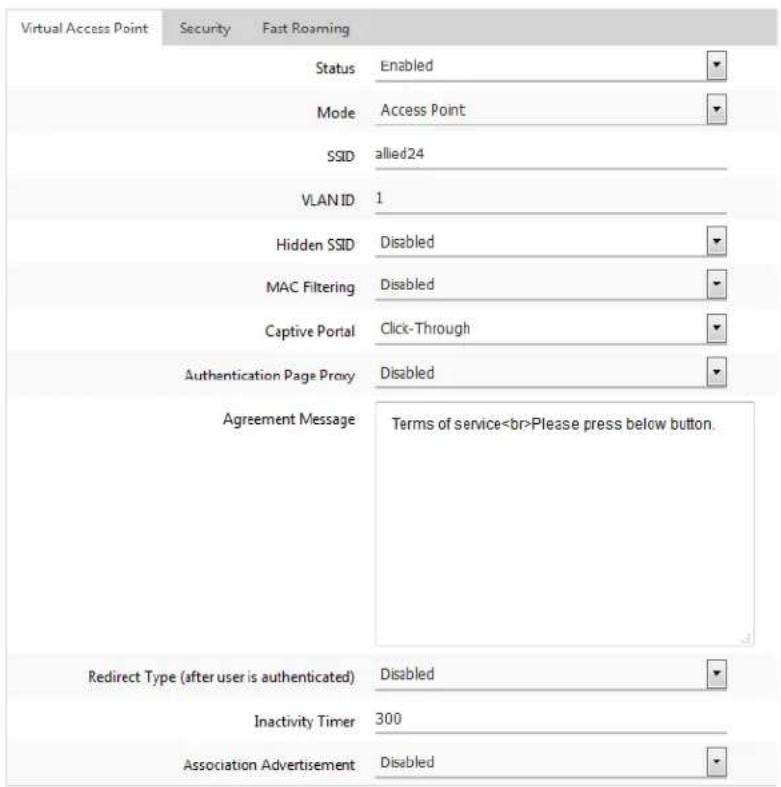
Figure 21. Captive Portal - Click-Through
- Select Disabled from the Authentication Page Proxy pull-down menu.
By default, the Authentication Page Proxy is disabled.
- Configure the parameters by referring to Table 14.
Table 14. Captive Portal
| Field Description | |
| Agreement Message | Enter Conditions of Use or other information in the HTML code format to be displayed in the introductory web page. |
| Redirect Type(after user is authenticated) | Select the following options to control a Web page to be displayed to wireless clients after they are allowed to access to the network.The options are:- Fixed URL: Allows you to specify a URL to redirect to wireless clients. When this option is selected, the Fixed URL field becomes available.- Session Keep: Displays a web page that wireless clients originally requested.- Disabled: Redirect is disabled. The welcome.html that you prepared is displayed. When the Capital Portal field is Click-Through and the Authentication Proxy Page is Disabled, the welcome page on the access point is displayed. This is the default setting. |
| Fixed URL Specify | the URL of a web page. Wireless clients are redirected to the specified web page. To use this field, the Redirect Type must be Fixed URL. |
Delegating a Proxy Server to Interact with Wireless Clients
- Click the SAVE & APPLY button to save and update the configuration.
You can delegate a proxy server to conduct authentication or interaction without authentication. The proxy server that you specify hosts web pages so that you must create web pages and applications on the proxy server.
To delegate a proxy server to interact with wireless clients, perform the following procedure:
- Select Settings > VAP / Security from the main menu.
- Select Radio1, Radio2, or Radio3 from the sub-menu. The default is Radio1. You can configure only one radio at a time.
- Select a VAP to configure from the next sub-menu. The default is VAP0. You can configure only one VAP at a time.
- Select the Virtual Access Point tab. See the example in Figure 20 on page 79.
- Select Click-Through from the Captive Portal pull-down menu. See Figure 22 on page 88.
- Select Enabled from the Authentication Page Proxy pull-down menu. See Figure 22 on page 88.
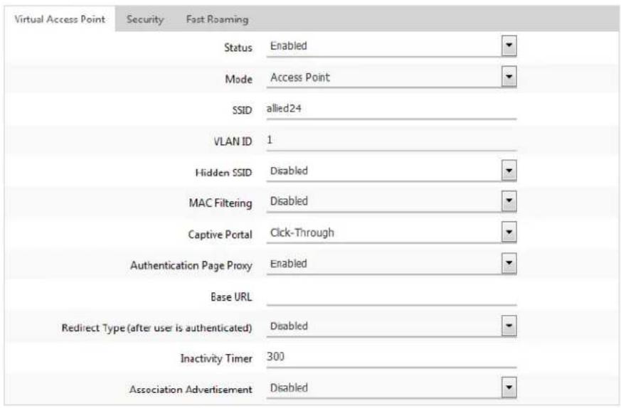
Figure 22. Captive Portal - Using a Proxy Server
- Specify a URL of your web server in the Base URL field.
- Specify the Redirect Type field by referring to Table 14 on page 86.
- Click the SAVE & APPLY button to save and update the configuration.
- Go to "Creating Pages in HTML for a Proxy Server" on page 91 to create the HTML files.
Delegating RADIUS Servers and a Proxy Server
You can delegate RADIUS servers to authentication wireless clients and delegate a proxy server to interaction with these wireless clients. The RADIUS servers authenticate wireless clients. The proxy server hosts web pages so that you can create your own web pages and applications on the proxy server.
To delegate RADIUS servers and a proxy server, perform the following procedure:
To display an authentication page hosted by a RADIUS server when wireless clients access to network resources, perform the following procedure:
- Select Settings > VAP / Security from the main menu.
- Select Radio1, Radio2, or Radio3 from the sub-menu. The default is Radio1. You can configure only one radio at a time.
-
Select a VAP to configure from the next sub-menu. The default is VAP0. You can configure only one VAP at a time.
-
Select the Virtual Access Point tab. See the example in Figure 20 on page 79.
- Select External RADIUS from the Captive Portal pull-down menu. See Figure 23.
- Select Enabled from the Authentication Page Proxy pull-down menu. See Figure 23.
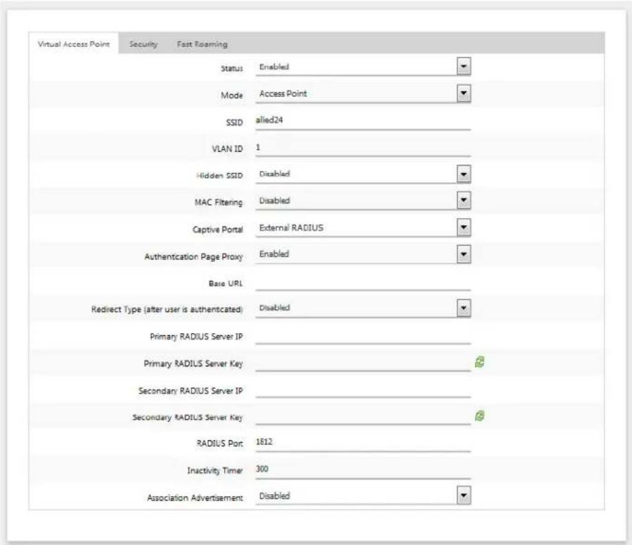
Figure 23. Captive Portal - External RADIUS
- Configure the parameters by referring to Table 15.
Table 15. Captive Portal - External RADIUS
| Field Description | |
| Authentication Page Proxy | See Table 14 on page 86. |
| Redirect Type See Table 14 on page 86. | |
| Primary RADIUS Server IP | Enter the IPv4 address of the primary FADIUS server. The default is 192.168.1.1 |
| Primary RADIUS Server Key | Enter the shared secret key for the primary RADIUS server.Here are the guidelines:☐ The key can be up to 128 alphanumeric characters.☐ It is case-sensitive.☐ It must be same on the access point and server.☐ The default is no key. |
| Secondary RADIUS Server IP | Enter the IPv4 address of a secondary RADIUS server. This field is optional. The access point sends authentication requests to this address if the primary RADIUS server does not respond to requests. |
| Secondary RADIUS Server Key | Enter the shared secret key for the secondary RADIUS server. |
| RADIUS Port Enter | the RADIUS port number of the RADIUS server. If you entered IP addresses for both primary and secondary servers, the units must be using the same port number. The range is 0 to 65535. The default is 1812. |
- Click the SAVE & APPLY button to save and update the configuration.
- Go to "Creating Login Pages in HTML When External RADIUS is Selected" on page 92 to create the HTML files.
Delegating RADIUS Servers to Authenticate Wireless Clients
You can delegate RADIUS servers to authenticate wireless clients. The pre-fixed HTML files stored in the access point are used to interact with wireless clients.
To delegate RADIUS servers, perform the following procedure:
- Select Settings > VAP / Security from the main menu.
- Select Radio1, Radio2, or Radio3 from the sub-menu. The default is Radio1. You can configure only one radio at a time.
-
Select a VAP to configure from the next sub-menu. The default is VAP0. You can configure only one VAP at a time.
-
Select the Virtual Access Point tab. See the example in Figure 20 on page 79.
- Select External RADIUS from the Captive Portal pull-down menu. See Figure 24.
- Select Disabled from the Authentication Page Proxy pull-down menu. See Figure 24.
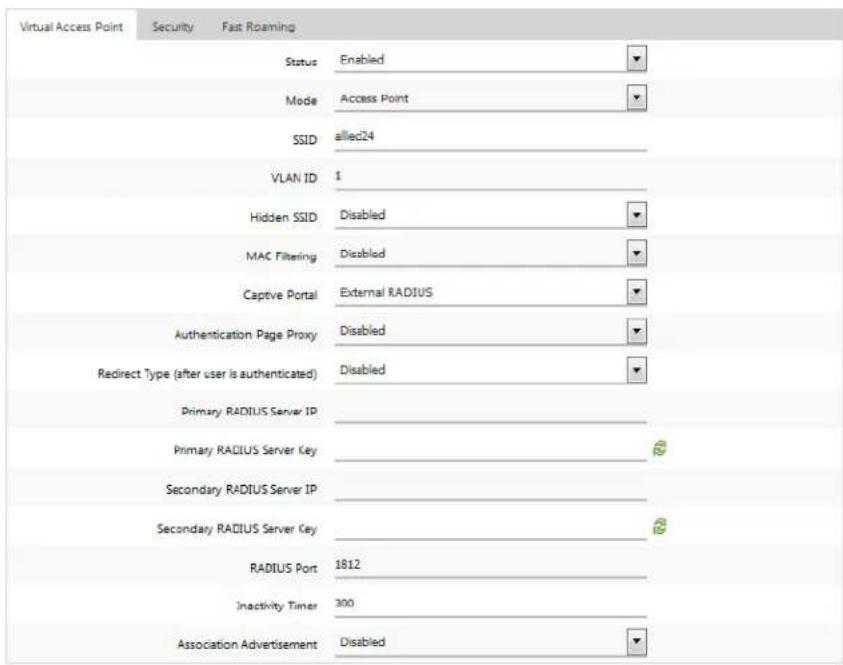
Figure 24. Captive Portal - External RADIUS
- Configure the parameters by referring to Table 15 on page 89.
- Click the SAVE & APPLY button to save and update the configuration.
Creating Pages in HTML for a Proxy Server
When you are configuring Captive Portal to be hosted by a proxy server, create the following HTML files on the proxy server:
☐ [Base URL]/click_through_login.html
☐ [Base URL]/click_through_login_fail.html
☐ [Base URL]/welcome.html (Optional)
Requirements for the click\_through\_login.html and click\_through\_login\_fail.html
Here is a list of requirements:
☐ You must include a
- Management Software User's Guide
- Contents
- Preface 13
- Chapter 1: Getting Started .... 17
- Chapter 2: Basic Settings ...... 33
- Chapter 3: Web Browser Interface .... 55
- Chapter 4: 2.4GHz and 5GHz Radios ...... 61
- Chapter 5: Virtual Access Points ......77
- Chapter 6: Quality of Service ....113
- Chapter 7: LAN1 and LAN2 Ports ....123
- Chapter 8: Wireless Distribution System Bridges ....133
- Chapter 9: Monitoring ....143
- Chapter 10: System Log 149
- Chapter 11: Maintenance 155
- List of Figures
- List of Tables
- Safety Symbols Used in this Document
- Note
- Caution
- Warning
- Contacting Allied Telesis
- Chapter 1
- Getting Started
- Features
- Management Tools
- Vista Manager EX and AWC Plug-in
- Starting the First Management Session
- Starting the First Management Session with a Direct Connection
- Starting the First Management Session without a DHCP Server
- Starting a Management Session
- Management Windows
- Saving and Applying Your Changes
- Ending Management Sessions
- What to Configure First
- Assigning a Dynamic IP Address from a DHCP Server
- Assigning a Static IP Address to the Access Point
- Setting the Date and Time with the Network Time Protocol (NTP)
- Configure the fields by referring to Table 4.
- Manually Setting the Date and Time
- Configuring SNMP Traps
- Enabling or Disabling the LEDs
- Enabling or Disabling the Reset Button
- Chapter 3
- Web Browser Interface
- Configuring the Web Browser Interface
- Changing the Manager's Login Name and Password
- Setting the Language of the Web Browser Interface
- Configuring the Radios
- Configuring Basic Radio Settings
- Configuring Advanced Radio Settings
- Displaying Radio Status
- Dynamic Frequency Selection
- Setting the Country Code Setting
- Selecting the Location
- Guidelines to Changing the Location
- Changing the Location to Outdoor
- Changing the Location to Indoor
- Chapter 5
- Virtual Access Points
- VAP Introduction
- Configuring Basic VAP Parameters
- Configuring Captive Portal
- Captive Portal Configurations
- Port Numbers The following port numbers are used with the IP address of the access point:
- Requiring Wireless Clients to Click the Agree Button to Access to the Network
- Delegating a Proxy Server to Interact with Wireless Clients
- Delegating RADIUS Servers and a Proxy Server
- Delegating RADIUS Servers to Authenticate Wireless Clients
- Creating Pages in HTML for a Proxy Server
- Requirements for the click\_through\_login.html and click\_through\_login\_fail.html
- HTML Code and Display Examples of Login Page
- Creating Login Pages in HTML When External RADIUS is Selected
- Requirements for the radius\_login.html and radius\_login\_fail.html
- Configuring VAP Security
- WPA Personal (Pre-Shared Key)
- Configuring VAP Fast Roaming
- Configuring the MAC Address List
- Displaying VAP and LAN Ports Statistics
- Advanced Settings
- Chapter 6
- Quality of Service
- Introduction to Quality of Service
- Configuring QoS Basic Settings
- Configuring AP EDCA Parameters
- Configuring Station EDCA Parameters
- Configuring the Management VLAN
- Enabling or Disabling the LAN2 Port
- Configuring PoE Negotiation with Link Layer Discovery Protocol
- Select LLDP from the sub-menu. Refer to Figure 37.
- Displaying the Status of LAN1 and LAN2 Ports
- Chapter 8
- Wireless Distribution System Bridges
- Introduction to Wireless Distribution Bridges
- Preparing Access Points for a WDS Bridge
- Displaying Basic System Information
- Displaying Neighboring Access Points
- Displaying Associated Clients
- Displaying the System Log
- Sending Log Messages to a Syslog Server
- Downloading the Configuration of the Access Point to Your Computer
- Restoring a Configuration to the Access Point
- Restoring the Default Settings to the Access Point
- Uploading New Management Software to the Access Point
- Rebooting the Access Point
- Sending Technical Support Information to Allied Telesis
Brand : Allied Telesis
Model : AT-TQm5403
Category : Access Point