TQ3600 - Access Point Allied Telesis - Free user manual and instructions
Find the device manual for free TQ3600 Allied Telesis in PDF.


| Product Type | Enterprise-class Wireless Access Point |
| Model | AT-TQ3600 |
| Wireless Standards | IEEE 802.11a/b/g/n |
| Frequency Bands | 2.4 GHz and 5 GHz (dual radio, 3x3:3 MIMO) |
| Maximum Data Rate | 450 Mbps per band (total 900 Mbps) |
| Antennas | Internal, 3x3:3 MIMO |
| Ethernet Port | 1x 10/100/1000Base-T (RJ-45) with Auto-Negotiation and auto MDI/MDIX |
| Power over Ethernet | IEEE 802.3af PoE (Class 3), maximum power consumption 11.4 W |
| Power Adapter (optional) | AT-TQ0091 AC/DC adapter, Input: 100-240 VAC, Output: 12 VDC, 2A |
| Dimensions (W x D x H) | 200.0 mm x 200.0 mm x 66.0 mm (7.9 in x 7.9 in x 2.6 in) |
| Weight | 1.2 kg (2.6 lb) |
| Mounting Options | Table, wall, or ceiling (with included bracket) |
| LEDs | PWR (green), SYS (amber), 10M/100M (link speed), 2.4GHz (green), 5GHz (green) |
| Reset Button | Recessed, restores factory defaults (hold 5 seconds) |
| Security Features | WPA/WPA2, TKIP/CCMP (AES), 802.1X, MAC filtering, rogue AP detection |
| Management | Web-based (HTTP/HTTPS), SNMPv1/v2c, Telnet, SSH |
| Operating Temperature | 0°C to 45°C (PoE) / 0°C to 40°C (AC adapter) |
| Storage Temperature | -20°C to 70°C (-4°F to 158°F) |
| Humidity | 5% to 80% non-condensing |
| Certifications | FCC Part 15 Class B, CE, IC, Wi-Fi Certified, RoHS |
Frequently Asked Questions - TQ3600 Allied Telesis
User questions about TQ3600 Allied Telesis
0 question about this device. Answer the ones you know or ask your own.
Ask a new question about this device
Download the instructions for your Access Point in PDF format for free! Find your manual TQ3600 - Allied Telesis and take your electronic device back in hand. On this page are published all the documents necessary for the use of your device. TQ3600 by Allied Telesis.
USER MANUAL TQ3600 Allied Telesis
Enterprise-class Wireless Access Point with IEEE802.11a/b/g/n Dual Radio
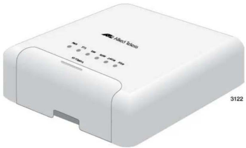
natural_image
White wireless device labeled 'Alieco Telezis' with ports and indicator lights (no readable text beyond branding)Installation Guide
613-001947 Rev. A
Copyright © 2014 Allied Telesis, Inc.
All rights reserved.
This product includes software licensed under the BSD License. As such, the following language applies for those portions of the software licensed under the BSD License:
Redistribution and use in source and binary forms, with or without modification, are permitted provided that the following conditions are met:
* Redistributions of source code must retain the above copyright notice, this list of conditions and the following disclaimer.
* Redistributions in binary form must reproduce the above copyright notice, this list of conditions and the following disclaimer in the documentation and/or other materials provided with the distribution.
* Neither the name of Allied Telesis, Inc. nor the names of the respective companies above may be used to endorse or promote products derived from this software without specific prior written permission.
THIS SOFTWARE IS PROVIDED BY THE COPYRIGHT HOLDERS AND CONTRIBUTORS "AS IS" AND ANY EXPRESS OR IMPLIED WARRANTIES, INCLUDING, BUT NOT LIMITED TO, THE IMPLIED WARRANTIES OF MERCHANTABILITY AND FITNESS FOR A PARTICULAR PURPOSE ARE DISCLAIMED. IN NO EVENT SHALL THE COPYRIGHT HOLDER OR CONTRIBUTORS BE LIABLE FOR ANY DIRECT, INDIRECT, INCIDENTAL, SPECIAL, EXEMPLARY, OR CONSEQUENTIAL DAMAGES (INCLUDING, BUT NOT LIMITED TO, PROCUREMENT OF SUBSTITUTE GOODS OR SERVICES; LOSS OF USE, DATA, OR PROFITS; OR BUSINESS INTERRUPTION) HOWEVER CAUSED AND ON ANY THEORY OF LIABILITY, WHETHER IN CONTRACT, STRICT LIABILITY, OR TORT (INCLUDING NEGLIGENCE OR OTHERWISE) ARISING IN ANY WAY OUT OF THE USE OF THIS SOFTWARE, EVEN IF ADVISED OF THE POSSIBILITY OF SUCH DAMAGE.
Copyright (c) [dates as appropriate to package] by The Regents of the University of California - All rights reserved. Copyright (c) 2000-2003 by Intel Corporation - All rights reserved. Copyright (c) 1997-2003, 2004 by Thomas E. Dickey dickey@invisible-island.net - All rights reserved. Copyright (c) 2001-2009 by Brandon Long (ClearSilver is now licensed under the New BSD License.) Copyright (c) 1984-2000 by Carnegie Mellon University - All rights reserved. Copyright (c) 2002,2003 by Matt Johnston - All rights reserved. Copyright (c) 1995 by Tatu Ylonen ylo@cs.hut.fi - All rights reserved. Copyright 1997-2003 by Simon Tatham. Portions copyright by Robert de Bath, Joris van Rantwijk, Delian Delchev, Andreas Schultz, Jeroen Massar, Wez Furlong, Nicolas Barry, Justin Bradford, and CORE SDI S.A. Copyright (c) 1989, 1991 by Free Software Foundation, Inc. (GNU General Public License, Version 2, June 1991). Copyright (c) 2002-2005 by Jouni Malinen jkmaline@cc.hut.fi and contributors. Copyright (c) 1991, 1999 by Free Software Foundation, Inc. (GNU Lesser General Public License, Version 2.1, February 1999). Copyright (c) 1998-2002 by Daniel Veillard - All rights reserved. Copyright (c) 1998-2004 by The OpenSSL Project - All rights reserved. Copyright (c) 1995-1998 by Eric Young (eay@cryptsoft.com) - All rights reserved.
This product also includes software licensed under the GNU General Public License available from:
http://www.gnu.org/licenses/gpl2.html
Allied Telesis is committed to meeting the requirements of the open source licenses including the GNU General Public License (GPL) and will make all required source code available.
If you would like a copy of the GPL source code contained in this product, please send us a request by registered mail including a check for US\$15 to cover production and shipping costs, and a CD with the GPL code will be mailed to you.
GPL Code Request
Allied Telesis Labs (Ltd)
PO Box 8011
Christchurch, New Zealand
No part of this publication may be reproduced without prior written permission from Allied Telesis, Inc.
Allied Telesis and the Allied Telesis logo are trademarks of Allied Telesis, Incorporated. All other product names, company names, logos or other designations mentioned herein are trademarks or registered trademarks of their respective owners.
Allied Telesis, Inc. reserves the right to make changes in specifications and other information contained in this document without prior written notice. The information provided herein is subject to change without notice. In no event shall Allied Telesis, Inc. be liable for any incidental, special, indirect, or consequential damages whatsoever, including but not limited to lost profits, arising out of or related to this manual or the information contained herein, even if Allied Telesis, Inc. has been advised of, known, or should have known, the possibility of such damages.
This product meets the following standards.
Federal Communications Commission Interference Statement
Declaration of Conformity
Manufacturer Name: Allied Telesis, Inc.
Declares that the product: Wireless access point with PoE powered device function
Model Number: AT-TQ3600
This device complies with Part 15 of the FCC Rules. Operation is subject to the following two conditions: (1) This device may not cause harmful interference, and (2) this device must accept any interference received, including interference that may cause undesired operation.
This equipment has been tested and found to comply with the limits for a Class B digital device, pursuant to Part 15 of the FCC Rules. These limits are designed to provide reasonable protection against harmful interference in a residential installation. This equipment generates, uses and can radiate radio frequency energy and, if not installed and used in accordance with the instructions, may cause harmful interference to radio communications. However, there is no guarantee that interference will not occur in a particular installation. If this equipment does cause harmful interference to radio or television reception, which can be determined by turning the equipment off and on, the user is encouraged to try to correct the interference by one of the following measures:
☐ Reorient or relocate the receiving antenna.
☐ Increase the separation between the equipment and receiver.
Connect the equipment into an outlet on a circuit different from that to which the receiver is connected.
Consult the dealer or an experienced radio/TV technician for help.
FCC Caution: Any changes or modifications not expressly approved by the party responsible for compliance could void the user's authority to operate this equipment.
This transmitter must not be co-located or operating in conjunction with any other antenna or transmitter.
For operation within 5.15 \~ 5.25GHz / 5.47 \~ 5.725GHz frequency range, it is restricted to indoor environment. The band from 5600-5650MHz will be disabled by the software during the manufacturing and cannot be changed by the end user. This device meets all the other requirements specified in Part 15E, Section 15.407 of the FCC Rules.
Radiation Exposure Statement:
This equipment complies with FCC radiation exposure limits set forth for an uncontrolled environment. This equipment should be installed and operated with minimum distance 21cm between the radiator & your body.
European Union Restriction of the Use of Certain Hazardous Substances (RoHS) in Electrical and Electronic Equipment
This Allied Telesis RoHS-compliant product conforms to the European Union Restriction of the Use of Certain Hazardous Substances (RoHS) in Electrical and Electronic Equipment. Allied Telesis ensures RoHS conformance by requiring supplier Declarations of Conformity, monitoring incoming materials, and maintaining manufacturing process controls.
Note
For additional regulatory statements, refer to Appendix B, "Regulatory Statements" on page 63.
Safety and Electromagnetic Emissions Certificates
| Standard Compliance | RoHs compliantEuropean Union RoHS (Directive 2011/65/EU of the European Parliament and of the Council of 8 June 2011 on the restriction of the use of certain hazardous substances in electrical and electronic equipment.) |
| Certificates CE | EACFCC/ICKCRCMSRMCWi-Fi CERTIFIED |
| Electromagnetic Compatibility (EMC) | EN 301 489-1EN 301 489-17EN 55022EN 55024EN 61000-3-2EN 61000-3-3EN 61000-4-2EN 61000-4-3EN 61000-4-4EN 61000-4-5EN 61000-4-6EN 61000-4-11AS/NZS CISPR 22FCC 47 CFR Part 15, Subpart BICES-003 |
| Medical (EMC) EN 60601-1-2 | |
| Radio Equipment EN | 300 328EN 301 893AS/NZS 4268FCC 47 CFR Part 15, Subpart CFCC 47 CFR Part 15, Subpart EFCC part 2RSS210RSS-GenRSS-102 |
| Safety EN 60950-1 | IEC 60950-1TUV-TUL 60950-1 |
Important: The 📌 indicates that a translation of the safety statement is available in a PDF document titled “Translated Safety Statements” on the Allied Telesis website at www.alliedtelesis.com/support/documentation. To view all the current documentation for the product, select the model number from the Product pull-down menu or enter the model name in the Search field.
Contents
Preface 13
Safety Symbols Used in this Document 14
Contacting Allied Telesis 15
Chapter 1: Overview ......17
Features 18
Front and Rear Panels 19
LAN Port 21
Power over Ethernet 21
Connector Type....21
Speed....21
Duplex Mode....21
Maximum Distance....21
Cable Requirements 21
Automatic MDIX Detection 22
Port Pinouts....22
LEDs....23
Reset Button....24
Chapter 2: Installing the Access Point ....25
Reviewing Safety Precautions....26
Unpacking the AT-TQ3600 Access Point 28
Installing the Access Point on a Table....29
Installing the Access Point on a Wall or Ceiling 33
Guidelines 33
Removing the Bottom Panel from the Access Point 37
Installing the Bottom Panel on a Wall or Ceiling 40
Installing the Access Point on the Bottom Panel....42
Installing Anti-theft Devices 50
Starting the Initial Management Session on the Access Point 51
Starting the Initial Management Session with a Direct Connection....52
Starting the Initial Management Session without a DHCP Server 53
Starting the Initial Management Session with a DHCP Server 53
Setting the Country Setting....55
Appendix A: Technical Specifications ....57
Physical Specifications 57
Environmental Specifications ....57
Power Specifications ....58
LAN Port 59
Safety and Electromagnetic Emissions Certifications 61
Appendix B: Regulatory Statements 63
Federal Communication Commission Interference Statement 64
Industry Canada Statement....66
Europe - EU Declaration of Conformity 68
Contents
Figures
Figure 1: Components on the Front and Rear Panels.... 19
Figure 2: AT-TQ0091 AC/DC Power Adapter.... 28
Figure 3: Installing the Rubber Feet 29
Figure 4: Connecting the Network Cable for Table or Desktop Installation.... 30
Figure 5: Connecting the Power Cable from the AT-TQ0091 AC/DC Adapter 31
Figure 6: Removing an AC Plug from the AT-TQ0091 AC/DC Power Adapter 31
Figure 7: Installing an AC Plug on the AT-TQ0091 AC/DC Power Adapter 32
Figure 8: Ventilation Slot 33
Figure 9: Wall Orientations 34
Figure 10: Heat Sinks 35
Figure 11: Screw Holes on the Bottom Panel of the AT-TQ3600 Bracket.... 36
Figure 12: Hole Dimensions 36
Figure 13: Opening Front Panel 37
Figure 14: Loosening the Captive Screw.... 38
Figure 15: Opening the Bottom Panel 39
Figure 16: Removing the Bottom Panel from the Wireless Access Point.... 40
Figure 17: Marking the Locations of the Bottom Panel Holes on the Wall or Ceiling 41
Figure 18: Attaching the Bottom Panel to the Wall or Ceiling.... 42
Figure 19: Installing the Access Point on the Bottom Panel.... 43
Figure 20: Connecting the Network Cable that is External to the Wall 44
Figure 21: Attaching the Network Cable through the Wall Opening 45
Figure 22: Connecting the DC Cable from the AT-TQ0091 Power Adapter.... 46
Figure 23: Closing the Access Point over the Bottom Panel 47
Figure 24: Tightening the Captive Screw 48
Figure 25: Holes for Anti-theft Devices.... 50
Figure 26: Logon Window.... 52
Figure 27: Modify Wireless Settings Window 55
Figure 28: Pin Numbers for the RJ-45 Connector on the LAN Port.... 59
List of Figures
Tables
Table 1. Components on the Front and Rear Panels ...... 20
Table 2. Twisted Pair Cable for the LAN Port 22
Table 3. LEDs on the AT-TQ3600 Access Point 23
Table 4. AT-TQ3600 Physical Specifications 57
Table 5. Environmental Specifications 57
Table 6. AT-TQ3600 Maximum Power Consumption 58
Table 7. AT-TQ0091 Power Adapter 58
Table 8. LAN Port Specifications 59
Table 9. MDI Pin Signals (10Base-T or 100Base-TX) 59
Table 10. MDI-X Pin Signals (10Base-T or 100Base-TX) 59
Table 11. 1000Base-T Connector Pinouts 60
Table 12. Safety and Electromagnetic Emissions Certificates 61
List of Tables
This guide contains the hardware installation instructions for the AT-TQ3600 Wireless Access Point. This preface contains the following sections:
☐ “Safety Symbols Used in this Document” on page 14
☐ “Contacting Allied Telesis” on page 15
Safety Symbols Used in this Document
This document uses the following conventions.
Note
Notes provide additional information.

Caution
Cautions inform you that performing or omitting a specific action may result in equipment damage or loss of data.

Warning
Warnings inform you that performing or omitting a specific action may result in bodily injury.
Contacting Allied Telesis
If you need assistance with this product, you may contact Allied Telesis technical support by going to the Support & Services section of the Allied Telesis web site at www.alliedtelesis.com/support. You can find links for the following services on this page:
☐ 24/7 Online Support — Enter our interactive support center to search for answers to your product questions in our knowledge database, to check support tickets, to learn about RMAs, and to contact Allied Telesis technical experts.
☐ USA and EMEA phone support — Select the phone number that best fits your location and customer type.
□ Hardware warranty information — Learn about Allied Telesis warranties and register your product online.
□ Replacement Services — Submit a Return Merchandise Authorization (RMA) request via our interactive support center.
□ Documentation — View the most recent installation and user guides, software release notes, white papers, and data sheets for your products.
□ Software Downloads — Download the latest software releases for your managed products.
For sales or corporate information, go to www.alliedtelesis.com/purchase.
Preface
This chapter describes the hardware components of the AT-TQ3600 Wireless Access Point. This chapter contains the following sections:
☐ "Features" on page 18
☐ "Front and Rear Panels" on page 19
☐ "LAN Port" on page 21
☐ “LEDs” on page 23
☐ "Reset Button" on page 24
Features
The main features of the product are listed here:
☐ Independent 2.4 and 5 GHz radios
□ IEEE 802.11a/b/g
☐ IEEE 802.11n 3x3:3 MIMO with internal antennas
☐ Data rate of 450 Mbps for the 2.4 GHz radio
☐ Data rate of 450 Mbps for the 5 GHz radio
☐ Wireless Distribution System (WDS) bridges
□ Access point clustering
☐ Rogue access point detection
□ Multiple SSIDs
☐ One 10/100/1000Base-T Ethernet port with Auto-Negotiation, auto MDI/MDIX, and IEEE 802.3af Power over Ethernet (PoE)
☐ IEEE 802.3 (10Base-T), IEEE 802.3u (100Base-TX), and IEEE 802.3ab (1000Base-T) compliance on the Ethernet port
☐ MAC address filtering for wireless access security
□ Broadcast and multicast rate limiting
□ Virtual access points for multiple broadcast domains
DHCP client
☐ RADIUS accounting with external RADIUS server
□ Network Time Protocol (NTP) client
☐ Domain name server (DNS) client
☐ IEEE 802.1x authentication
☐ WPA-Personal and WPA-Enterprise with WPA, WPA2, TKIP, and CCMP (AES) authentication and encryption
□ Static WEP encryption
☐ HTTP and HTTPS web browser management
☐ SNMPv1 and v2c management
□ Quality of Service
□ Event log
□ Syslog client
☐ Table, wall, or ceiling installation
Front and Rear Panels
The components of the unit are illustrated in Figure 1.
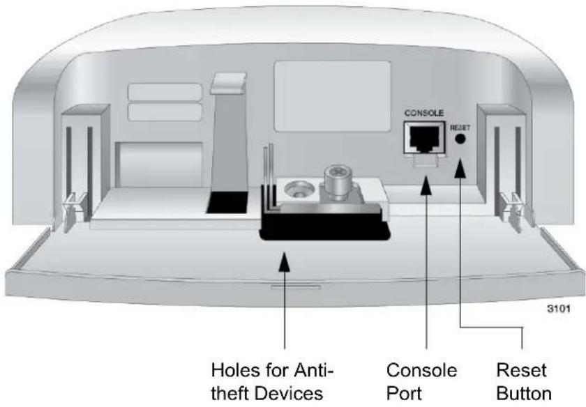
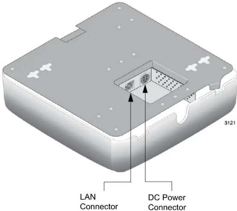
Figure 1. Components on the Front and Rear Panels
The components are listed in Table 1.
Table 1. Components on the Front and Rear Panels
| Field Description | |
| Holes for anti-theft devices | Holes for a padlock and Torx screw. For information, refer to “Installing Anti-theft Devices” on page 50 |
| Console Port The Console Port | Port is for manufacturing purposes only. |
| Reset Button The Reset button | on returns the parameter settings on the access point to their default settings. For information, refer to “Reset Button” on page 24. |
| LAN Port The LAN port connects | ects the access point to your wired network. It supports PoE. If you connect the port to an Ethernet switch that supports PoE, you do not have to use the AC/DC adapter to power the device. For information, refer to “LAN Port” on page 21 |
| DC Power Connector This connector is for the AT-TQ0091 Power Adapter. The access point can be powered with PoE on the LAN port or the power adapter. The AT-TQ0091 Power Adapter does not come with the access point. It has to be ordered separately from Allied Telesis. | |
LAN Port
| The LAN port is used to connect the device to your Local Area Network (LAN), typically through an Ethernet switch. | |
| Power over Ethernet | The AT-TQ3600 Access Point supports Power over Ethernet on the LAN port. The unit is a PoE class 3 powered device with a maximum power consumption of 11.4 watts. When the port is connected to an PoE Ethernet switch, the unit receives its power over the network cable that carries the network traffic. If you use the PoE feature, you do not need to use the AC/DC power adapter that comes with the access point. |
| Connector Type | The LAN port has an 8-pin RJ-45 connector. The port uses four pins at 10 or 100 Mbps and all eight pins at 1000 Mbps. The pin assignments are listed in “LAN Port” on page 59. |
| Speed | The port can operate at 10, 100, or 1000 Mbps. The speed is set automatically with Auto-Negotiation. You cannot disable Auto-Negotiation. |
| NoteThe LAN port should be connected to a network device that also adjusts its speed with Auto-Negotiation. If the network device does not support Auto-Negotiation, the LAN port operates at 10 Mbps, which may reduce network performance. | |
| Duplex Mode | The LAN port can operate in either half- or full-duplex mode at 10 or 100 Mbps, and full-duplex mode at 1000 Mbps. The port is IEEE 802.3u-compliant and uses Auto-Negotiation to set the duplex mode. You cannot disable Auto-Negotiation on the port. |
| NoteThe LAN port should be connected to a network device that also sets its duplex mode with Auto-Negotiation. If the network device does not support Auto-Negotiation, the LAN port operates at half-duplex mode. This may result in a duplex mode mismatch if the network device is operating at full duplex. | |
| Maximum Distance | The port has a maximum operating distance of 100 meters (328 feet). |
| Cable Requirements | The cable requirements for the LAN port are listed in Table 2 on page 22. |
Table 2. Twisted Pair Cable for the LAN Port
| Cable Type | 10Mbps 100Mbps 1000Mbps | |||||
| Non-PoE | PoE | Non-PoE | PoE | Non-PoE | PoE | |
| Standard TIA/EIA 568-B-compliant Category 3 shielded or unshielded cabling with 100 ohm impedance and a frequency of 16 MHz. | Y | e | s | N | o | N |
| Standard TIA/EIA 568-A-compliant Category 5 shielded or unshielded cabling with 100 ohm impedance and a frequency of 100 MHz. | Yes Yes | Yes Yes | No No | |||
| Standard TIA/EIA 568-B-compliant Enhanced Category 5 (Cat 5e) shielded or unshielded cabling with 100 ohm impedance and a frequency of 100 MHz. | Yes Yes | Yes Yes | Yes Yes | |||
| Standard TIA/EIA 568-B-compliant Category 6 or 6a shielded cabling. | Yes Yes | Yes Yes | Yes Yes | |||
Automatic MDIX Detection
The 10/100/1000 Mbps twisted-pair port is IEEE 802.3ab compliant and features automatic MDIX detection when operating at 10 or 100 Mbps. (Automatic MDIX detection does not apply to 1000 Mbps.) This feature automatically configures the port to MDI or MDI-X depending on the wiring configuration of the port on the Ethernet switch.
You may not disable automatic MDIX detection. For automatic MDIX detection to work properly, it must also be present on the Ethernet switch. The LAN port defaults to MDIX if it is connected to a network device that does not support automatic MDIX detection.
Port Pinouts
Refer to Table 9 on page 59 for the port pinouts of the LAN port when it is operating at 10 or 100 Mbps in the MDI configuration and Table 10 on page 59 for the MDI-X configuration. Refer to Table 11 on page 60 for the port pinouts when the port is operating at 1000 Mbps.
The LEDs on the AT-TQ3600 Access Point are described in Table 3.
Table 3. LEDs on the AT-TQ3600 Access Point
| LED State Description | ||
| PWR Solid Green | Green The unit is receiving DC power that is within the normal operating range. | |
| Off The power supply is not receiving power from either the AC/DC power adapter or a PoE Ethernet switch. | ||
| SYS Amber The access point is loading its firmware. | ||
| Off The unit is operating normally. | ||
| 10M and 100M | 10M: On 100M: Off | The Ethernet port is operating at 10 Mbps. |
| 10M: Off 100M: On | The Ethernet port is operating at 100 Mbps. | |
| 10M: On 100M: On | The Ethernet port is operating at 1000 Mbps. | |
| 2.4GHz Green | The 2.4GHz radio is sending and receiving radio waves. | |
| 5GHz Green | The 5GHz radio is sending and receiving radio waves. | |
Note
You may turn off the LEDs with the management software.
Reset Button
The Reset button on the front panel is used to return the parameter settings of the unit to their default values. You might use the button if you want to discard the current configuration of the device or because you forgot the password to the manager account and cannot manage the unit.
You may disable the button using the management software. If the unit is installed in a non-secure area, you might want to disable the button to prevent unauthorized individuals from pressing it and potentially disrupting the operations of your wireless network.
The Reset button is recessed to prevent it from being accidentally pressed. To press the button, use a pointed object, such as the end of a straightened paperclip. Hold the button for five seconds and release. The access point resets and loads its default configuration in a process that takes one minute to complete. In its default configuration, the access point attempts to contact a DHCP server from its LAN port for its IP address configuration. If it receives a response, it configures its IP address according to the settings from the DHCP server. If it does not receive a response, it uses the default address 192.168.1.230 and subnet mask 255.255.255.0. For instructions on how to start a management session when the access point is at its default configuration, refer to “Starting the Initial Management Session on the Access Point” on page 51.
Chapter 2
Installing the Access Point
This chapter describes how to install the AT-TQ3600 Wireless Access Point. This chapter contains the following sections:
☐ “Reviewing Safety Precautions” on page 26
☐ “Unpacking the AT-TQ3600 Access Point” on page 28
☐ “Installing the Access Point on a Table” on page 29
☐ “Installing the Access Point on a Wall or Ceiling” on page 33
☐ “Installing Anti-theft Devices” on page 50
☐ "Starting the Initial Management Session on the Access Point" on page 51
☐ "Setting the Country Setting" on page 55
Note
The non-US model of this product has a country code setting that must be set during the initial management session of the unit. The setting ensures that the unit operates in compliance with the laws and regulations of your country or region.
For the US model the country code is preset and cannot be changed. Per FCC regulations, the country code setting for all WiFi products marketed in the US must be fixed to US operational channels only.
Reviewing Safety Precautions
Please review the following safety precautions before you begin to install the access point.
Note
The indicates that a translation of the safety statement is available for viewing in the “Translated Safety Statements” document on our web site at http://www.alliedtelesis.com/support.

Warning
To prevent electric shock, do not remove the cover. No user-serviceable parts inside. This unit contains hazardous voltages and should only be opened by a trained and qualified technician. To avoid the possibility of electric shock, disconnect electric power to the product before connecting or disconnecting the LAN cables. E1

Warning
Do not work on equipment or cables during periods of lightning activity. E2

Warning
Power cord is used as a disconnection device. To de-energize equipment, disconnect the power cord. E3
Note
Pluggable Equipment. The socket outlet shall be installed near the equipment and shall be easily accessible. E5

Caution
Air vents must not be blocked and must have free access to the room ambient air for cooling. E6

Warning
Operating Temperature. This product is designed for a maximum ambient temperature of 40^ degrees C with the AC/DC adapter and 45^ degrees C with Power over Ethernet.

Warning
Do not touch the heat sinks inside the access point. Refer to Figure 10 on page 35.

Warning
To reduce the risk of electric shock, the PoE ports on this product must not connect to cabling that is routed outside the building where this device is located. E40

Warning
This equipment is intended for indoor use only.

Warning
Do not touch the captive screw on the front panel when the wireless access point is operating because it can reach a high temperature.
Note
All Countries: Install product in accordance with local and National Electrical Codes. E8
Note
This product is not approved for use in a computer room as defined in the Standard for Protection of Electronic Computer/Data Processing Equipment, ANSI/NFPA 75.
Note
If you are not using PoE to power to the unit, use only an approved AC/DC adapter.
Note
You should verify that your PoE network adheres to the standards of a SELV (separated extra-low voltage) circuit before using the PoE feature on the wireless access point.
Unpacking the AT-TQ3600 Access Point
As you unpack the access point, check the shipping container for the components the following items:
☐ One AT-TQ3600 Wireless Access Point
☐ One AT-TQ3600 Wireless Access Point Quick Install Guide
☐ Four rubber feet
If any item is missing or damaged, contact your Allied Telesis sales representative for assistance.
If you are not using the PoE feature on the LAN port of the access point to power the device, you need to separately order the AT-TQ0091 AC/DC Power Adapter. The adapter comes with four regional AC plugs. (One of the AC plugs comes pre-installed on the adapter.) Refer to Figure 2.
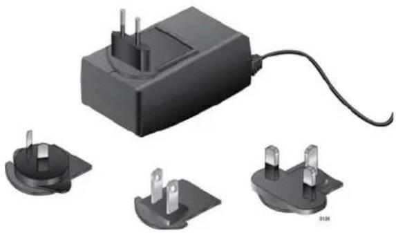
natural_image
Black electrical plug with three terminal pins and a cable, shown alongside two separate socket bases (no text or symbols visible)Figure 2. AT-TQ0091 AC/DC Power Adapter
Do one of the following:
☐ To install the unit on a table, go to "Installing the Access Point on a Table" on page 29.
☐ To install the unit in a wall or ceiling, go to "Installing the Access Point on a Wall or Ceiling" on page 33
Installing the Access Point on a Table
To install the access point on a table, perform the following procedure:
- Place the access point upside down on the table or desk selected for the device.
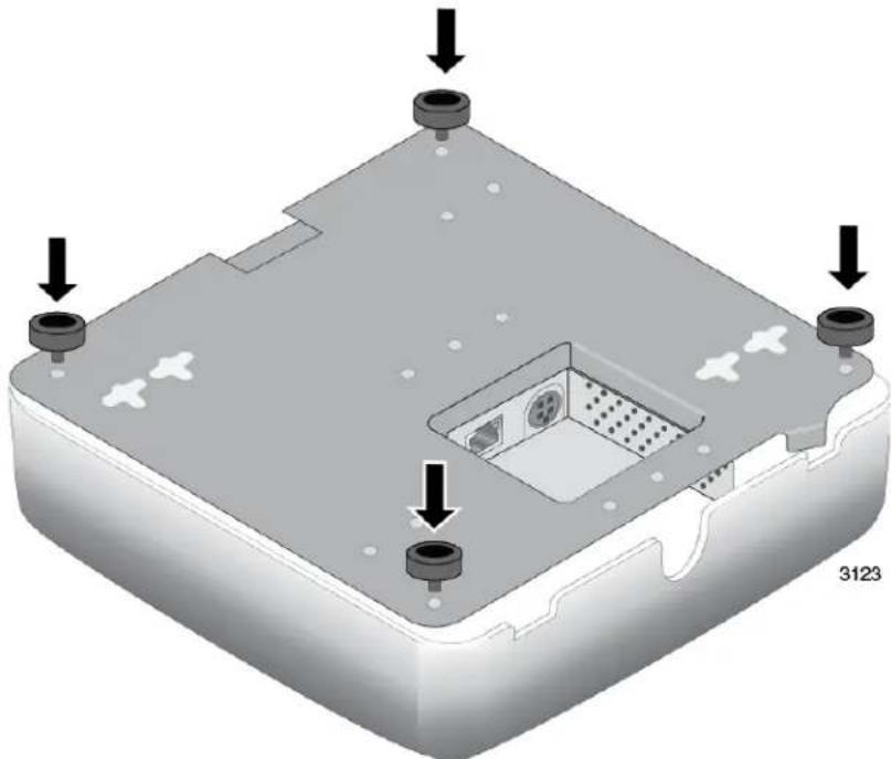
- Install the rubber feet that come with the wireless access point to the bottom panel. Refer to Figure 3.
natural_image
3D diagram of a device casing with mounting points and internal components, no text or symbols presentFigure 3. Installing the Rubber Feet
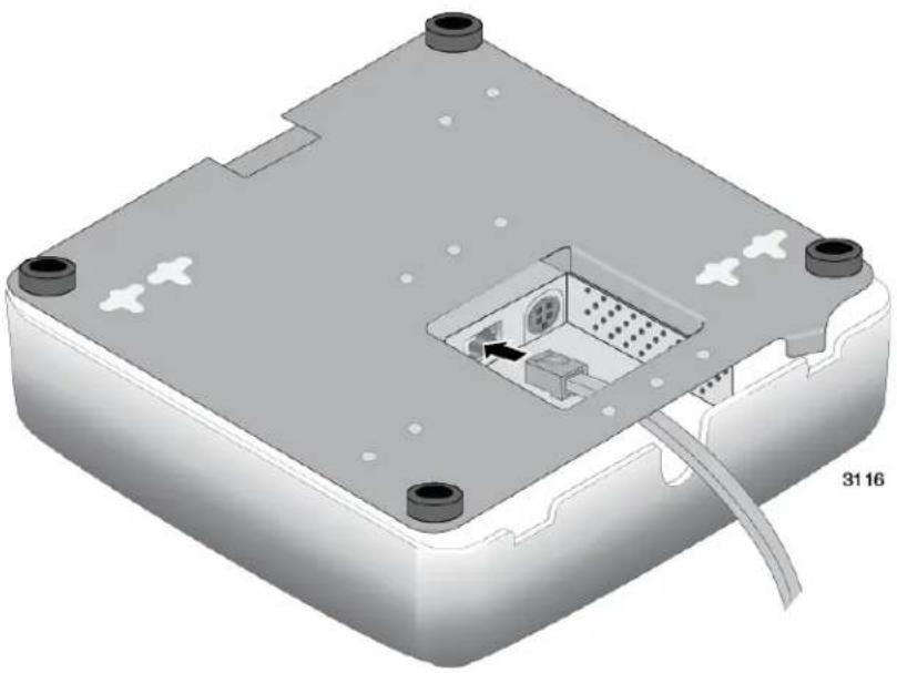
- Route a network cable through the notch in the cover and under the bottom panel, and connect it to the LAN port on the access point. Refer to Figure 4 on page 30. The specifications of the cable are listed in Table 2 on page 22.
natural_image
3D CAD rendering of a device housing with internal components and mounting holes (no text or symbols)Figure 4. Connecting the Network Cable for Table or Desktop Installation
-
If you have not already done so, connect the other end of the network cable to a port on an Ethernet switch.
-
Do one of the following:
☐ If the access point is to be powered with the AT-TQ0091 AC/DC Power Adapter, continue with this procedure to attach the power adapter.
☐ If the access point is to be powered with the PoE feature on the LAN Port, turn the access point right side up. The installation procedure is complete. Go to “Installing Anti-theft Devices” on page 50 or “Starting the Initial Management Session on the Access Point” on page 51.
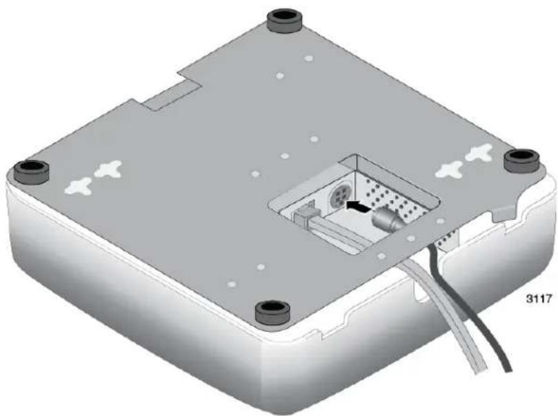
- Route the DC power cable from the AT-TQ0091 AC/DC Power Adapter through the notch in the cover and under the bottom panel, and connect it to the DC-IN connector on the access point. Refer to Figure 5 on page 31.
natural_image
3D technical illustration of an electronic device casing with internal components and mounting holes (no text or symbols)Figure 5. Connecting the Power Cable from the AT-TQ0091 AC/DC Adapter
- Turn the access point right side up on the table.
- Check the AC plug on the AC/DC Power Adapter to see if it is the correct plug for your region. If it is not the correct plug, remove it by pushing down on the release tab and sliding it from the slot on the adapter. Refer to Figure 6.
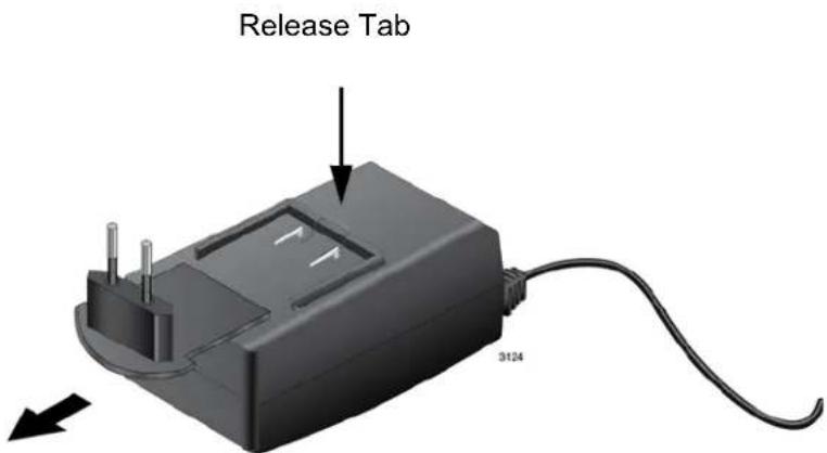
Figure 6. Removing an AC Plug from the AT-TQ0091 AC/DC Power Adapter
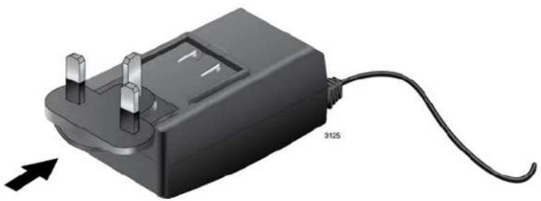
- Slide the correct AC plug for your region into the slot on the adapter until it clicks into place. Refer to Figure 7 on page 32.
natural_image
3D illustration of a black electrical plug with two pins and a cable, labeled '3125' (no text or symbols on the device itself)Figure 7. Installing an AC Plug on the AT-TQ0091 AC/DC Power Adapter
- Connect the AC plug on the power cord to an appropriate AC power source. Refer to Table 7 on page 58 for the power specifications of the power adapter.
After installing the access point on the table, go to "Installing Anti-theft Devices" on page 50 or "Starting the Initial Management Session on the Access Point" on page 51.
Installing the Access Point on a Wall or Ceiling
This procedure contains the following sections.
☐ "Guidelines" on page 33
☐ "Removing the Bottom Panel from the Access Point" on page 37
☐ "Installing the Bottom Panel on a Wall or Ceiling" on page 40
☐ "Installing the Access Point on the Bottom Panel" on page 42
Guidelines
Please review the following guidelines before installing the access point on a wall or ceiling:
☐ The selected location must not block the ventilation slot around the base of the unit. Refer to Figure 8.
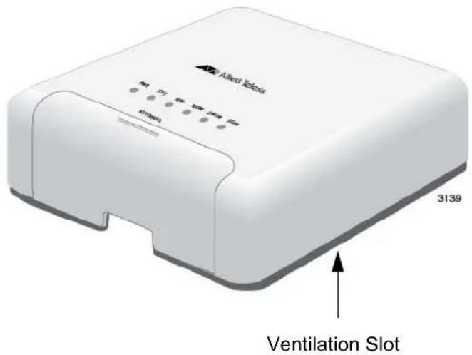
Figure 8. Ventilation Slot
☐ You should verify that the wall or ceiling material is strong enough to support the weight of the access point.
☐ You have to provide the four screws and, if required for your installation, the wall anchors that are to be used to secure the bottom panel to the wall or ceiling.
☐ You may install the access point on a wall in the three orientations shown in Figure 9 on page 34.
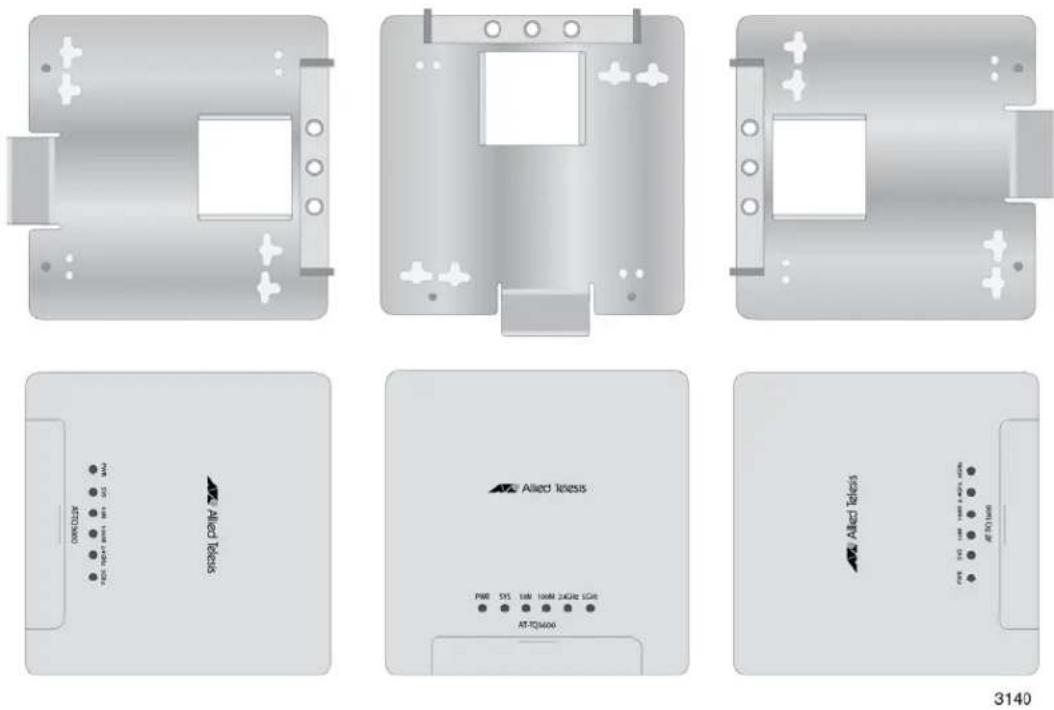
Figure 9. Wall Orientations
☐ You may not install the access point upside down on a wall.
☐ The location must have an AC power source if you are using the AT-TQ0091 Power Adapter.
☐ If the LAN cable is external to the wall, you must route the cable through the notch in the rear panel of the cover. If the cable is internal to the wall, you may route it either through the notch in the cover or through the hole in the bottom panel.
☐ You must not route the LAN cable inside the access point such that it touches the heat sinks because that could damage the unit. Refer to Figure 10 on page 35.
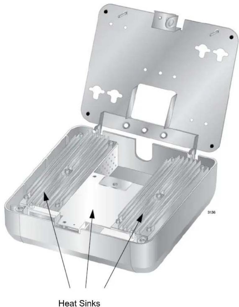
Figure 10. Heat Sinks
☐ The bottom panel has eight screw holes. Refer to Figure 11 on page 36. The holes are grouped in pairs. The unit should be secured to the wall or ceiling with a minimum of four screws. You may use either screw hole in a pair when choosing the holes.
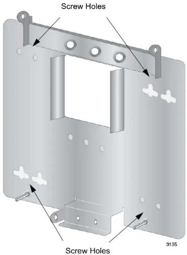
Figure 11. Screw Holes on the Bottom Panel of the AT-TQ3600 Bracket
☐ The holes have a diameter of 4.5 mm (0.2 in.). Refer to Figure 12.
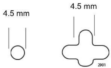
Figure 12. Hole Dimensions
Removing the Bottom Panel from the Access Point
To remove the bottom panel from the access point, preform the following procedure:
- Place the access point on a table or desk.
- Open the front panel. Refer to Figure 13.
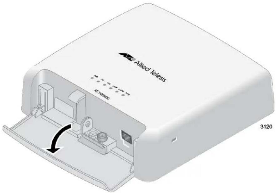
Figure 13. Opening Front Panel
- Use a #2 Phillips-head screwdriver to loosen the captive screw that secures the bottom panel to the wireless access point. Refer to Figure 14 on page 38.
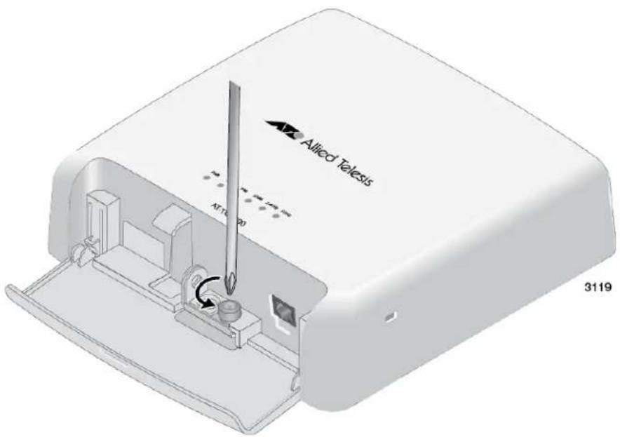
Figure 14. Loosening the Captive Screw
- Carefully turn the access point upside down.
- Open the bottom panel. Refer to Figure 15 on page 39.
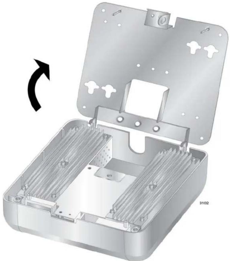
natural_image
3D rendering of an open metal enclosure with internal channels and mounting holes, showing a rotational arrow indicating rotation (no text or symbols present)Figure 15. Opening the Bottom Panel
- Slide the bottom panel slightly to the left to free it from the pin hinges on the access point, and lift the panel off the access point. Refer to Figure 16 on page 40.
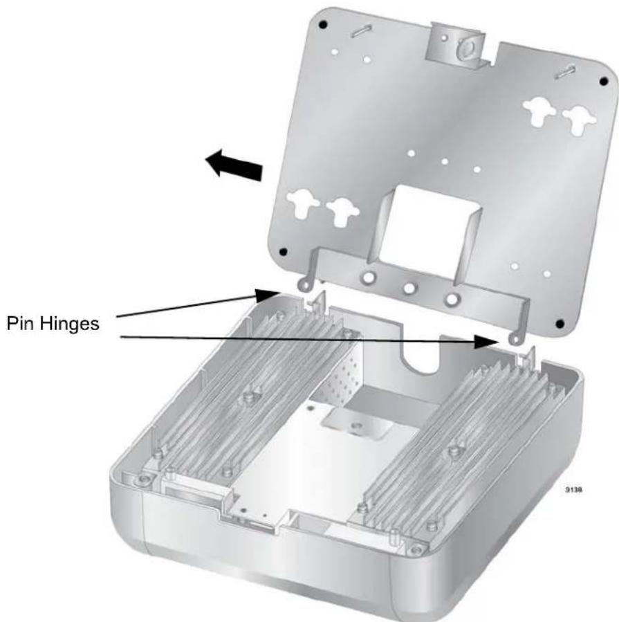
Figure 16. Removing the Bottom Panel from the Wireless Access Point
You may now perform "Installing the Bottom Panel on a Wall or Ceiling" on page 40.
Installing the Bottom Panel on a Wall or Ceiling
To install the bottom panel on a wall or ceiling, perform the following procedure:
Note
If you are using wall anchors, start with step 1. If you are not using wall anchors, start with step 4.
- To install wall anchors, hold the bottom panel at the selected wall or ceiling location and with a pencil or pen mark the locations of the four screw holes that are to be used to secure the panel. Refer to Figure 17 on page 41.
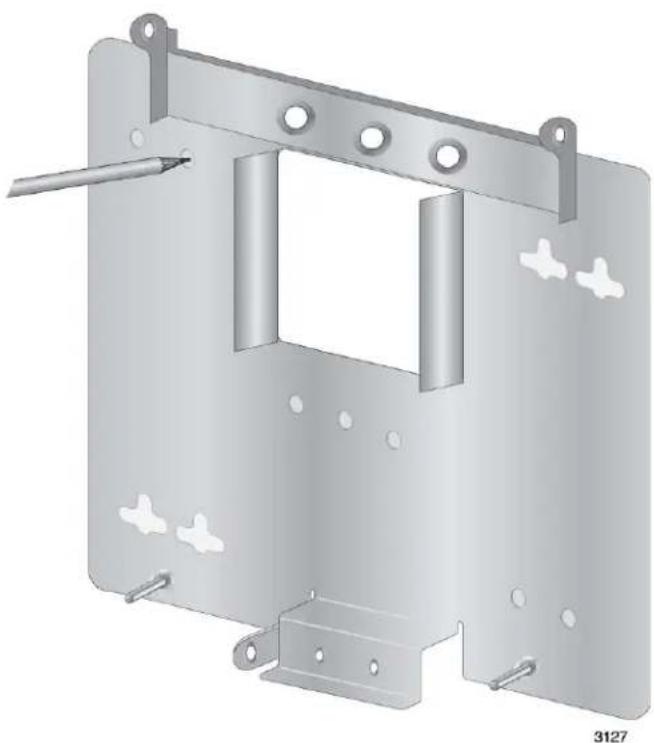
natural_image
3D rendering of a metal enclosure with mounting brackets and a tool inserted (no text or symbols)Figure 17. Marking the Locations of the Bottom Panel Holes on the Wall or Ceiling
-
If necessary, predrill the holes for the anchors.
-
Install the wall anchors.
-
Have someone hold the bottom panel at the selected wall or ceiling location while you secure it to with four self-tapping screws (not provided with the access point). Refer to Figure 18 on page 42.
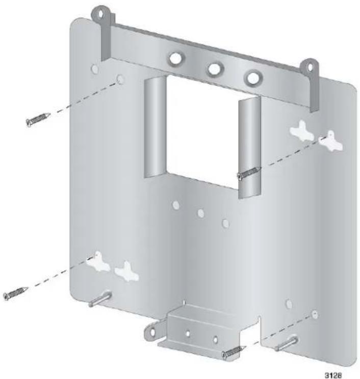
natural_image
3D CAD model of a mechanical bracket assembly with mounting holes and internal cavity (no text or symbols)Figure 18. Attaching the Bottom Panel to the Wall or Ceiling
You may now perform "Installing the Access Point on the Bottom Panel" on page 42.
Installing the Access Point on the Bottom Panel
To install the access point on the bottom panel on a wall or ceiling, perform the following procedure:
- Carefully lift the access point and slide the pin hinges into the holes on the bottom panel. Refer to Figure 19 on page 43.
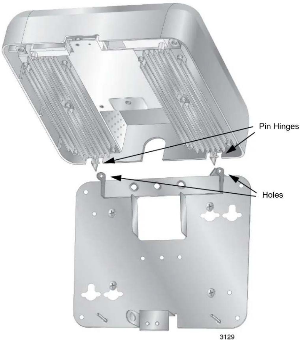
Figure 19. Installing the Access Point on the Bottom Panel
- If the LAN cable is external to the wall or ceiling, route it through the notch in the cover and connect it to the LAN port. Refer to Figure 20 on page 44.
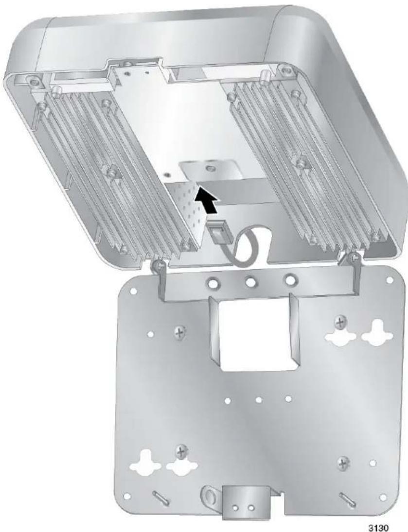
natural_image
Technical illustration of an open electronic device casing with internal components and mounting holes (no text or symbols)Figure 20. Connecting the Network Cable that is External to the Wall
- If the network cable comes through a wall opening, route the cable either through the notch in the cover, as shown in Figure 20 or through the hole in the bottom panel, as shown in Figure 21 on page 45, and connect it to the LAN port on the access point.
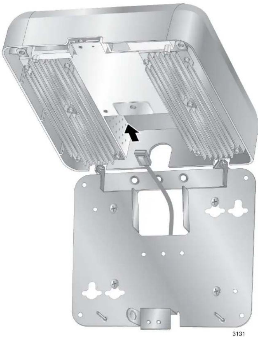
natural_image
Technical illustration of an open electronic device casing with internal components and mounting holes (no text or symbols)Figure 21. Attaching the Network Cable through the Wall Opening
- If the access point is to be powered with the AT-TQ0091 Power Adapter, route the DC cable from the adapter through the notch in the cover and connect it to the DC-IN port on the access point. Refer to Figure 22 on page 46.
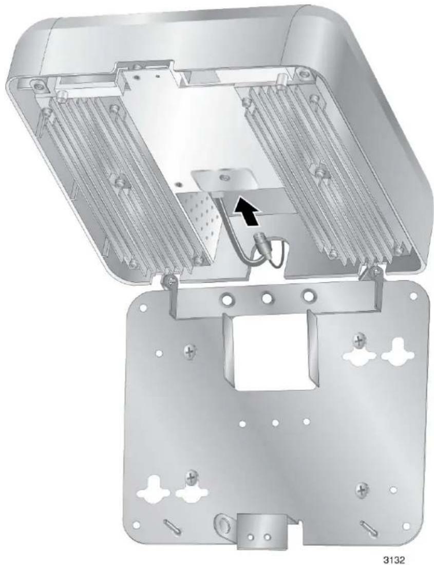
natural_image
Technical illustration of an open electronic device housing with internal components and mounting holes (no text or symbols)Figure 22. Connecting the DC Cable from the AT-TQ0091 Power Adapter
- Carefully close the access point over the bottom panel. Refer to Figure 23 on page 47.

natural_image
Technical illustration of an open electronic device casing with internal components and mounting holes, showing a circular arrow indicating rotation (no text or symbols present)Figure 23. Closing the Access Point over the Bottom Panel
- Open the front panel and use a #2 Phillips-head screwdriver to tighten the captive screw to secure the access point to the bottom panel. Refer to Figure 24 on page 48.
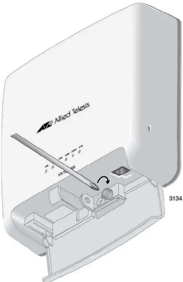
Figure 24. Tightening the Captive Screw
-
Close the front panel.
-
If you have not already done so, connect the network cable from the wireless access point to a port on an Ethernet switch.
-
Do one of the following:
☐ If the access point is using PoE, the installation is complete. Go to "Installing Anti-theft Devices" on page 50 or "Starting the Initial Management Session on the Access Point" on page 51.
☐ If the access point is using the AT-TQ0091 AC/DC Power Adapter, perform the rest of this procedure to check and, if necessary, change the AC plug on the adapter.
- Check the AC plug on the AT-TQ0091 AC/DC Power Adapter to see if it is the correct plug for your region. If it is not the correct plug, remove it by pushing down on the release tab and sliding it from the slot on the adapter. Refer to Figure 6 on page 31.
- Slide the correct plug for your region into the slot on the adapter until it clicks into place. Refer to Figure 7 on page 32.
- Connect the adapter to an appropriate AC power source. Refer to Table 7 on page 58 for the power specifications of the power adapter.
After installing the access point on a wall or ceiling, go to "Installing Anti-theft Devices" on page 50 or "Starting the Initial Management Session on the Access Point" on page 51.
Installing Anti-theft Devices
The access point has holes for anti-theft devices. Refer to Figure 25. You may want to install one or more anti-theft devices if the access point is installed in a non-secure area.
Note
Anti-theft devices are not available from Allied Telesis.
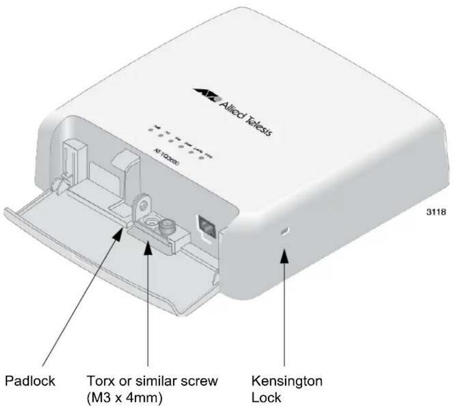
Figure 25. Holes for Anti-theft Devices
A padlock or Torx screw can be used to secure the access point to the bottom panel when it is installed on a wall or ceiling. A Kensington lock can be used to secure the device when it is installed on a wall, ceiling, or table.
Starting the Initial Management Session on the Access Point
When you power on the access point for the first time, it queries the subnet on the LAN port for a DHCP server. If a DHCP server responds to its query, the unit uses the IP address the server assigns to it. If there is no DHCP server, the access point uses the default IP address 192.168.1.230.
There are a several ways to start the initial management session on the access point. One way is to establish a direct connection between your computer and the unit by connecting an Ethernet cable to the Ethernet port on the computer and the LAN port on the access point. This procedure requires changing the IP address on your computer to make it a member of the same subnet as the default IP address on the access point. You might perform this procedure if your network does not have a DHCP server and you want to configure the access point before connecting it to your network.
The initial management session may also be performed while the device is connected to your network. However, If your network does not have a DHCP server, you still have to change the IP address of your computer to match the subnet of the default address of the access point. Furthermore, if your network is divided into virtual LANs (VLANs), you have to be sure to connect the access point and your computer to ports on an Ethernet switch that are members of the same VLAN.
If your network has a DHCP server, use the IP address the server assigns it to start the management session.
The instructions for starting the initial management session are found in the following sections:
☐ “Starting the Initial Management Session with a Direct Connection” on page 52
☐ “Starting the Initial Management Session without a DHCP Server” on page 53
☐ "Starting the Initial Management Session with a DHCP Server" on page 53
Note
The initial management session of the access point has to be conducted through the LAN port because the default setting for the radios is off.
Starting the Initial Management Session with a Direct Connection
To start the management session with a direct Ethernet connection between your computer and the access point, perform the following procedure:
Note
If the unit is using PoE for power and you did not order an AC/DC adapter with the unit, you cannot perform this procedure because it requires removing the network cable from the LAN port. Instead, perform one of the other procedures in this section to start the initial management session.
- Connect one end of a network cable to the LAN port on the access point and the other end to the Ethernet network port on your computer. (This requires removing the network cable that you connected to the LAN port earlier in these instructions.)
- Change the IP address on your computer to 192.168.1.n, where n is a number from 1 to 254, but not 230. Refer to the documentation that accompanies your computer for instructions on how to set the IP address.
- Set the subnet mask on your computer to 255.255.255.0.
- Power on the access point.
- Start the web browser on your computer.
- Enter the IP address 192.168.1.230 in the URL field of the browser.
You should now see the logon window, shown in Figure 26.

Allied Telesis
User Name Password
Logon
Figure 26. Logon Window
- Enter "manager" for the username and "friend" for the password. The username and password are case-sensitive.
Starting the Initial Management Session without a DHCP Server
This procedure explains how to start the initial management session on the access point when the LAN port is connected to an Ethernet switch on a network that does not have a DHCP server. To start the management session, perform the following procedure:
- If your network has VLANs, check to be sure that your computer and the access point are connected to ports on the Ethernet switch that are members of the same VLAN. This might require accessing the management software on the switch and listing the VLANs and their port assignments. For example, if the access point is connected to a port that is a member of the Sales VLAN, your computer must be connected to a port that is also a member of that VLAN. If your network is small and does not have VLANs or routers, you may connect your computer to any port on the Ethernet switch.
- Change the IP address on your computer to 192.168.1.n, where n is a number from 1 to 254, but not 230. Refer to the documentation that accompanies your computer for instructions on how to set the IP address.
- Set the subnet mask on your computer to 255.255.255.0.
- Power on the access point.
- Start the web browser on your computer.
- Enter the IP address 192.168.1.230 in the URL field of the browser. You should now see the logon window, shown in Figure 26 on page 52.
- Enter "manager" for the username and "friend" for the password. The username and password are case-sensitive.
Starting the Initial Management Session with a DHCP Server
This procedure explains how to start the initial management session on the access point when the LAN port is connected to a network that has a DHCP server. This procedure assumes that you have already configured the DHCP server to assign the access point all the necessary configuration information (e.g., IP address and default gateway) for your network. To start the management session, perform the following procedure:
- Power on the access point.
- Start the web browser on your computer.
- Enter the IP address of the access point in the URL field of the browser. This is the IP address assigned to the unit by the DHCP server. If you do not know the address, refer to the DHCP server.
-
You should now see the logon window in Figure 26 on page 52.
-
Enter "manager" for the username and "friend" for the password. The username and password are case-sensitive.
Setting the Country Setting
You should set the country setting during the initial management session of the access point to ensure that the device operates in compliance with the codes and regulations of your region or country.
Note
The non-US model of this product has a country code setting that must be set during the initial management session of the unit. The setting ensures that the unit operates in compliance with the laws and regulations of your country or region.
For the US model the country code is preset and cannot be changed. Per FCC regulations, the country code setting for all WiFi products marketed in the US must be fixed to US operational channels only.
To set the country setting, perform the following procedure:
- Select Wireless Settings from the Manage menu.
The access point displays the Modify wireless settings window, shown in Figure 27.
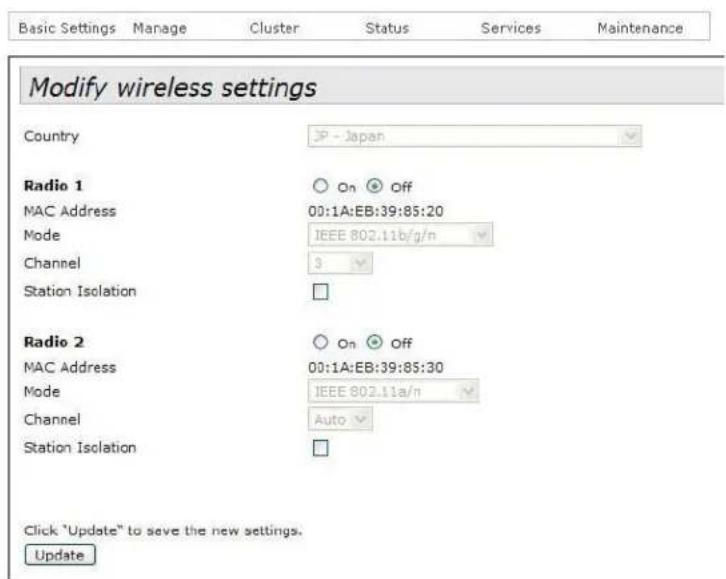
Figure 27. Modify Wireless Settings Window
- Select the Country pull-down menu and select your country or region.
Note
If the Country pull-down menu is deactivated and cannot be changed, the country parameter was set when the unit was manufactured. If the setting is not correct for your country or region, contact your Allied Telesis sales representative for assistance.
The access point displays a confirmation prompt.
- Click OK to change the country setting or Cancel to cancel the procedure.
If you click OK, the access point changes the country setting and disables both radios on the access point.
This procedure does not require clicking the Update button.
You must now reboot the access point. The new country setting is not active until the unit is rebooted. To reboot the unit, either power off and on the unit or continue with these steps:
-
From the Maintenance menu, select Configuration.
-
Click the Reboot button in the To Reboot the Access Point section of the "Manage the Access Point's Configuration" window.
-
When the access point displays a confirmation prompt, click OK to reboot the unit or Cancel to cancel the procedure.
-
To resume managing the unit, wait for it to complete initializing its management software and then start a new management session.
For more instructions on how to configure the features of the access point, refer to the AT-TQ3600 Wireless Access Point User's Guide.
Physical Specifications
Table 4. AT-TQ3600 Physical Specifications
| Dimensions (W x D x H) 200.0 mm x 200.0 mm x 66.0 mm(7.9 in. x 7.9 in. x 2.6 in.) |
| Weight 1.2 kg (2.6 lb.) |
Environmental Specifications
Table 5. Environmental Specifications
| Operating Temperature of the Access Point When Using PoE | 0°C to 45°C (32°F to 113°F) |
| Operating Temperature of the Access Point When Using the AC/DC Adapter | 0°C to 40°C (32°F to 104°F) |
| Storage Temperature -20°C to 70°C | C (-4°F to 158°F) |
| Operating Humidity 5% to 80% non-condensing | |
| Storage Humidity 5% to 95% non-condensing | |
Power Specifications
Table 6. AT-TQ3600 Maximum Power Consumption
| AT-TQ3600 12 watts |
Table 7. AT-TQ0091 Power Adapter
| Input Range 100 | ~240 Vac |
| Input Frequency 47-63 Hz | |
| Input Power Consumption (no load) | <0.3W max. |
| Output Voltage +12 VDC | |
| Output Current 2A max. |
Table 8. LAN Port Specifications
| Connector RJ-45 | |
| Standards IEEE 802.3 (10Base-T) | IEEE 802.3u (100Base-TX)IEEE 802.3ab (1000Base-T) |
| PoE standard IEEE 802.3af (class 3) |
Figure 28 illustrates the pin layout of the LAN port.
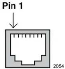
Figure 28. Pin Numbers for the RJ-45 Connector on the LAN Port
Table 9 lists the pin signals when the port is operating in the MDI configuration at 10 or 100 Mbps.
Table 9. MDI Pin Signals (10Base-T or 100Base-TX)
| Pin Signal | |
| 1 | TX+ |
| 2 | TX- |
| 3 | RX+ |
| 6 | RX- |
Table 10 lists the pin signals for the MDI-X configuration at 10 or 100 Mbps.
Table 10. MDI-X Pin Signals (10Base-T or 100Base-TX)
| Pin Signal | |
| 1 | RX+ |
| 2 | RX- |
| 3 | TX+ |
| 6 | TX- |
Table 11 lists the pin signals when the LAN port is operating at 1000 Mbps.
Table 11. 1000Base-T Connector Pinouts
| Pin Pair Signal | ||
| 1 1 TX and | RX+ | |
| 2 1 TX and | RX- | |
| 3 2 TX and | RX+ | |
| 4 3 TX and | RX+ | |
| 5 3 TX and | RX- | |
| 6 2 TX and | RX- | |
| 7 4 TX and | RX+ | |
| 8 4 TX and | RX- | |
Safety and Electromagnetic Emissions Certifications
Table 12. Safety and Electromagnetic Emissions Certificates
| Standard Compliance | RoHs compliantEuropean Union RoHS (Directive 2011/65/EU of the European Parliament and of the Council of 8 June 2011 on the restriction of the use of certain hazardous substances in electrical and electronic equipment.) |
| Certificates CE | EACFCC/ICKCRCMSRMCWi-Fi CERTIFIED |
| Electromagnetic Compatibility (EMC) | EN 301 489-1EN 301 489-17EN 55022EN 55024EN 61000-3-2EN 61000-3-3EN 61000-4-2EN 61000-4-3EN 61000-4-4EN 61000-4-5EN 61000-4-6EN 61000-4-11AS/NZS CISPR 22FCC 47 CFR Part 15, Subpart BICES-003 |
| Medical (EMC) EN 60 | 601-1-2 |
| Radio Equipment EN | 300 328EN 301 893AS/NZS 4268FCC 47 CFR Part 15, Subpart CFCC 47 CFR Part 15, Subpart EFCC part 2RSS210RSS-GenRSS-102 |
| Safety EN 60950-1 | IEC 60950-1TUV-TUL 60950-1 |
This appendix contains the following regulatory statements:
☐ "Federal Communication Commission Interference Statement" on page 64
☐ "Industry Canada Statement" on page 66
☐ “Europe - EU Declaration of Conformity” on page 68
Federal Communication Commission Interference Statement
This device complies with Part 15 of the FCC Rules. Operation is subject to the following two conditions: (1) This device may not cause harmful interference, and (2) this device must accept any interference received, including interference that may cause undesired operation.
This equipment has been tested and found to comply with the limits for a Class B digital device, pursuant to Part 15 of the FCC Rules. These limits are designed to provide reasonable protection against harmful interference in a residential installation. This equipment generates, uses and can radiate radio frequency energy and, if not installed and used in accordance with the instructions, may cause harmful interference to radio communications. However, there is no guarantee that interference will not occur in a particular installation. If this equipment does cause harmful interference to radio or television reception, which can be determined by turning the equipment off and on, the user is encouraged to try to correct the interference by one of the following measures:
☐ Reorient or relocate the receiving antenna.
☐ Increase the separation between the equipment and receiver.
☐ Connect the equipment into an outlet on a circuit different from that to which the receiver is connected.
□ Consult the dealer or an experienced radio/TV technician for help.
FCC Caution: Any changes or modifications not expressly approved by the party responsible for compliance could void the user's authority to operate this equipment.
This transmitter must not be co-located or operating in conjunction with any other antenna or transmitter.
For operation within 5.15 \~ 5.25GHz / 5.47 \~ 5.725GHz frequency range, it is restricted to indoor environment. The band from 5600-5650MHz will be disabled by the software during the manufacturing and cannot be changed by the end user. This device meets all the other requirements specified in Part 15E, Section 15.407 of the FCC Rules.
Radiation Exposure Statement
This equipment complies with FCC radiation exposure limits set forth for an uncontrolled environment. This equipment should be installed and operated with minimum distance 21cm between the radiator & your body.
Country Code Selection (WiFi Devices)
Note
The non-US model of this product has a country code setting that must be set during the initial management session of the unit. The setting ensures that the unit operates in compliance with the laws and regulations of your country or region.
For the US model the country code is preset and cannot be changed. Per FCC regulations, the country code setting for all WiFi products marketed in the US must be fixed to US operational channels only.
Industry Canada Statement
This device complies with RSS-210 of the Industry Canada Rules. Operation is subject to the following two conditions: (1) This device may not cause harmful interference, and (2) this device must accept any interference received, including interference that may cause undesired operation.
This Class A digital apparatus complies with Canadian ICES-003.
(i) the device for operation in the band 5150-5250 MHz is only for indoor use to reduce the potential for harmful interference to co-channel mobile satellite systems;
(ii) the maximum antenna gain permitted for devices in the bands 5250-5350 MHz and 5470-5725 MHz shall comply with the e.i.r.p. limit; and
(iii) the maximum antenna gain permitted for devices in the band 5725-5825 MHz shall comply with the e.i.r.p. limits specified for point-to-point and non point-to-point operation as appropriate.
(iv) Users should also be advised that high-power radars are allocated as primary users (i.e. priority users) of the bands 5250-5350 MHz and 5650-5850 MHz and that these radars could cause interference and/or damage to LE-LAN devices.
Avertissement:
Radiation Exposure Statement:
This equipment complies with IC radiation exposure limits set forth for an uncontrolled environment. This equipment should be installed and operated with minimum distance 21cm between the radiator & your body.
Europe - EU Declaration of Conformity
This device complies with the essential requirements of the R&TTE Directive 1999/5/EC. The following test methods have been applied in order to prove presumption of conformity with the essential requirements of the R&TTE Directive 1999/5/EC:
EN60950-1
Safety of Information Technology Equipment
□ EN 300 328
Electromagnetic compatibility and Radio spectrum Matters (ERM); Wideband Transmission systems; Data transmission equipment operating in the 2,4 GHz ISM band and using spread spectrum modulation techniques; Harmonized EN covering essential requirements under article 3.2 of the R&TTE Directive,
□ EN 301 893
Broadband Radio Access Networks (BRAN); 5 GHz high performance RLAN; Harmonized EN covering essential requirements of article 3.2 of the R&TTE Directive
□ EN 301 489-1
Electromagnetic compatibility and Radio Spectrum Matters (ERM); ElectroMagnetic Compatibility (EMC) standard for radio equipment and services; Part 1: Common technical requirements.
□ EN 301 489-17
Electromagnetic compatibility and Radio spectrum Matters (ERM); ElectroMagnetic Compatibility (EMC) standard for radio equipment and services; Part 17: Specific conditions for 2,4 GHz wideband transmission systems and 5 GHz high performance RLAN equipment
This device is a 5GHz wideband transmission system (transceiver), intended for use in all EU member states and EFTA countries, except in France and Italy where restrictive use applies.
In Italy the end-user should apply for a license at the national spectrum authorities in order to obtain authorization to use the device for setting up outdoor radio links and/or for supplying public access to telecommunications and/or network services.
This device may not be used for setting up outdoor radio links in France and in some areas the RF output power may be limited to 10 mW EIRP in the frequency range of 2454 - 2483.5 MHz. For detailed information the end-user should contact the national spectrum authority in France.
CE0700①
| Česky [Czech] | Allied Telesis tímto prohlašuje, že tento wireless access point je ve shodě se základními požadavky a dalšími příslušnými ustanoveními směrnice 1999/5/ES. |
| Dansk [Danish] | Undertegnede Allied Telesis erklærer herved, at følgende udstyr wireless access point overholder de væsentlige krav og øvrige relevante krav i direktiv 1999/5/EF. |
| Deutsch [German] | Hiermit erklärt Allied Telesis, dass sich das Gerät wireless access point in Übereinstimmung mit den grundlegenden Anforderungen und den übrigen einschlägigen Bestimmungen der Richtlinie 1999/5/EG befindet. |
| Eesti [Estonian] | Käesolevaga kinnitab Allied Telesis seadme wireless access point vastavust direktiivi 1999/5/EÜ põhinõuetele ja nimetatud direktiivist tulenevatele teistele asjakohastele sätetele. |
| English Hereby | , Allied Telesis, declares that this wireless access point is in compliance with the essential requirements and other relevant provisions of Directive 1999/5/EC. |
| Español [Spanish] | Por medio de la presente Allied Telesis declara que el wireless access point cumple con los requisitos esenciales y cualesquiera otras disposiciones aplicables o exigibles de la Directiva 1999/5/CE. |
| Ελληνική [Greek] | ME THN ΠΑΡΟΥΣΑ Allied Telesis ΔΗΛΩΝΕΙ OTI wireless access point ΣΥΜΜΟΡΦΩΝΕΤΑΙ ΠΡΟΣ ΤΙΣ ΟΥΣΙΩΔΕΙΣ ΑΠΑΙΤΗΣΕΙΣ ΚΑΙ ΤΙΣ ΛΟΙΠΕΣ ΣΧΕΤΙΚΕΣ ΔΙΑΤΑΞΕΙΣ ΤΗΣ ΟΔΗΓΙΑΣ 1999/5/EK. |
| Français [French] | Par la présente Allied Telesis déclare que l'appareil wireless access point est conforme aux exigences essentielles et aux autres dispositions pertinentes de la directive 1999/5/CE. |
| Italiano [Italian] | Con la presente Allied Telesis dichiara che questo wireless access point è conforme ai requisiti essenziali ed alle altre disposizioni pertinenti stabilite dalla direttiva 1999/5/CE. |
| Latviski [Latvian] | Ar šo Allied Telesis deklarē, ka wireless access point atbilst Direktīvas 1999/5/EK būtiskajām prasībām un citiem ar to saistītajiem noteikumiem. |
| Lietuvių[Lithuanian] | Šiuo Allied Telesis deklaruoja, kad šis wireless access point atitinka esminius reikalavimus ir kitas 1999/5/EB Direktyvos nuostatas. |
| Nederlands[Dutch] | Hierbij verklaart Allied Telesis dat het toestel wireless access point in overeenstemming is met de essentiële eisen en de andere relevante bepalingen van richtlijn 1999/5/EG. |
| Malti[Maltese] | Hawnhekk, Allied Telesis, jiddikjara li dan wireless access point jikkonforma mal-ħtiġijiet essenzjali u ma provvedimenti oħrajn relevanti li hemm fid-Dirrettiva 1999/5/EC. |
| Magyar[Hungarian] | Alulírott, Allied Telesis nyilatkozom, hogy a wireless access point megfelel a vonatkozó alapvető követelményeknek és az 1999/5/EC irányelv egyéb előírásainak. |
| Polski[Polish] | Niniejszym Allied Telesis oświadcza, że wireless access point jest zgodny z zasadniczymi wymogami oraz pozostałymi stosownymi postanowieniami Dyrektywy 1999/5/EC. |
| Português[Portuguese] | Allied Telesis declara que este wireless access point está conforme com os requisitos essenciais e outras disposições da Directiva 1999/5/CE. |
| Slovensko[Slovenian] | Allied Telesis izjavlja, da je ta wireless access point v skladu z bistvenimi zahtevami in ostalimi relevantnimi določili direktive 1999/5/ES. |
| Slovensky[Slovak] | Allied Telesis týmto vyhlasuje, że wireless access point spĺňa základné požiadavky a všetky príslušné ustanovenia Smernice 1999/5/ES. |
| Suomi[Finnish] | Allied Telesis vakuuttaa täten että wireless access point tyyppinen laite on direktiivin 1999/5/EY oleellisten vaatimusten ja sitä koskevien direktiivin muiden ehtojen mukainen. |
| Svenska[Swedish] | Härmed intygar Allied Telesis att denna wireless access point står I överensstämmelse med de väsentliga egenskapskrav och övriga relevanta bestämmelser som framgår av direktiv 1999/5/EG. |
- Installation Guide
- Federal Communications Commission Interference Statement
- European Union Restriction of the Use of Certain Hazardous Substances (RoHS) in Electrical and Electronic Equipment
- Note
- Contents
- Preface 13
- Chapter 1: Overview ......17
- Chapter 2: Installing the Access Point ....25
- Appendix A: Technical Specifications ....57
- Appendix B: Regulatory Statements 63
- Figures
- Tables
- Safety Symbols Used in this Document
- Caution
- Warning
- Contacting Allied Telesis
- Features
- Front and Rear Panels
- LAN Port
- Automatic MDIX Detection
- Port Pinouts
- Reset Button
- Chapter 2
- Installing the Access Point
- Reviewing Safety Precautions
- Unpacking the AT-TQ3600 Access Point
- Installing the Access Point on a Table
- Installing the Access Point on a Wall or Ceiling
- Guidelines
- Removing the Bottom Panel from the Access Point
- Installing the Bottom Panel on a Wall or Ceiling
- Installing the Access Point on the Bottom Panel
- Installing Anti-theft Devices
- Starting the Initial Management Session on the Access Point
- Starting the Initial Management Session with a Direct Connection
- Allied Telesis
- Starting the Initial Management Session without a DHCP Server
- Starting the Initial Management Session with a DHCP Server
- Setting the Country Setting
- Physical Specifications
- Environmental Specifications
- Power Specifications
- Safety and Electromagnetic Emissions Certifications
- Federal Communication Commission Interference Statement
- Radiation Exposure Statement
- Country Code Selection (WiFi Devices)
- Industry Canada Statement
- Avertissement:
- Radiation Exposure Statement:
- Europe - EU Declaration of Conformity
- CE0700①
Brand : Allied Telesis
Model : TQ3600
Category : Access Point