AT-MWS2533AP - Access Point Allied Telesis - Free user manual and instructions
Find the device manual for free AT-MWS2533AP Allied Telesis in PDF.


| Product Type | Wireless Access Point |
| Brand | Allied Telesis |
| Model | AT-MWS2533AP |
| Wireless Standards | 2.4 GHz: 802.11b/g/n; 5 GHz: 802.11n/ac |
| Maximum Data Rate | 2.4 GHz: up to 300 Mbps; 5 GHz: up to 867 Mbps (approx) |
| Interfaces | 2 x Gigabit Ethernet (LAN1, LAN2) with PoE+ (LAN1) |
| Power Supply | PoE+ (802.3at) or optional DC adapter (AT-MWS0091) |
| Management | Web-based GUI, SNMP v1/v2c/v3, HTTPS, Email alerts |
| Security Features | WEP, WPA/WPA2-PSK, WPA/WPA2-Enterprise, MAC filtering, Client isolation, MFP |
| Virtual Access Points (VAPs) | Up to 8 per radio (2.4 GHz + 5 GHz), plus up to 2 guest networks |
| VLAN Support | Yes, including management VLAN and per-VAP VLAN assignment (1-4094) |
| Spanning Tree Protocol (STP) | Yes (on AT-MWS2533AP model) |
| Link Aggregation (LACP) | Yes (on AT-MWS2533AP model) |
| Fast Roaming / Fast Handover | Yes, with configurable RSSI threshold |
| LED Indicators | Power, LAN, WLAN 2.4 GHz, WLAN 5 GHz (individually controllable) |
| Antenna | Internal (no external antenna ports mentioned) |
| Dimensions | Approx. 210 x 210 x 45 mm (estimated) |
| Weight | Approx. 1 kg (estimated) |
| Operating Temperature | 0°C to 40°C (typical) |
| Certifications | Wi-Fi CERTIFIED, WPA2, WMM |
Frequently Asked Questions - AT-MWS2533AP Allied Telesis
User questions about AT-MWS2533AP Allied Telesis
0 question about this device. Answer the ones you know or ask your own.
Ask a new question about this device
Download the instructions for your Access Point in PDF format for free! Find your manual AT-MWS2533AP - Allied Telesis and take your electronic device back in hand. On this page are published all the documents necessary for the use of your device. AT-MWS2533AP by Allied Telesis.
USER MANUAL AT-MWS2533AP Allied Telesis
Management Software User's Guide
the solution : the network
613-002445 Rev.B
Copyright © 2017 Allied Telesis, Inc.
All rights reserved.
This product includes software licensed under the BSD License. As such, the following language applies for those portions of the software licensed under the BSD License:
Redistribution and use in source and binary forms, with or without modification, are permitted provided that the following conditions are met:
* Redistributions of source code must retain the above copyright notice, this list of conditions and the following disclaimer.
* Redistributions in binary form must reproduce the above copyright notice, this list of conditions and the following disclaimer in the documentation and/or other materials provided with the distribution.
* Neither the name of Allied Telesis, Inc. nor the names of the respective companies above may be used to endorse or promote products derived from this software without specific prior written permission.
THIS SOFTWARE IS PROVIDED BY THE COPYRIGHT HOLDERS AND CONTRIBUTORS "AS IS" AND ANY EXPRESS OR IMPLIED WARRANTIES, INCLUDING, BUT NOT LIMITED TO, THE IMPLIED WARRANTIES OF MERCHANTABILITY AND FITNESS FOR A PARTICULAR PURPOSE ARE DISCLAIMED. IN NO EVENT SHALL THE COPYRIGHT HOLDER OR CONTRIBUTORS BE LIABLE FOR ANY DIRECT, INDIRECT, INCIDENTAL, SPECIAL, EXEMPLARY, OR CONSEQUENTIAL DAMAGES (INCLUDING, BUT NOT LIMITED TO, PROCUREMENT OF SUBSTITUTE GOODS OR SERVICES; LOSS OF USE, DATA, OR PROFITS; OR BUSINESS INTERRUPTION) HOWEVER CAUSED AND ON ANY THEORY OF LIABILITY, WHETHER IN CONTRACT, STRICT LIABILITY, OR TORT (INCLUDING NEGLIGENCE OR OTHERWISE) ARISING IN ANY WAY OUT OF THE USE OF THIS SOFTWARE, EVEN IF ADVISED OF THE POSSIBILITY OF SUCH DAMAGE.
Copyright (c) [dates as appropriate to package] by The Regents of the University of California - All rights reserved. Copyright (c) 2000-2003 by Intel Corporation - All rights reserved. Copyright (c) 1997-2003, 2004 by Thomas E. Dickey dickey@invisible-island.net - All rights reserved. Copyright (c) 2001-2009 by Brandon Long (ClearSilver is now licensed under the New BSD License.) Copyright (c) 1984-2000 by Carnegie Mellon University - All rights reserved. Copyright (c) 2002,2003 by Matt Johnston - All rights reserved. Copyright (c) 1995 by Tatu Ylonen ylo@cs.hut.fi - All rights reserved. Copyright 1997-2003 by Simon Tatham. Portions copyright by Robert de Bath, Joris van Rantwijk, Delian Delchev, Andreas Schultz, Jeroen Massar, Wez Furlong, Nicolas Barry, Justin Bradford, and CORE SDI S.A. Copyright (c) 1989, 1991 by Free Software Foundation, Inc. (GNU General Public License, Version 2, June 1991). Copyright (c) 2002-2005 by Jouni Malinen jkmaline@cc.hut.fi and contributors. Copyright (c) 1991, 1999 by Free Software Foundation, Inc. (GNU Lesser General Public License, Version 2.1, February 1999). Copyright (c) 1998-2002 by Daniel Veillard - All rights reserved. Copyright (c) 1998-2004 by The OpenSSL Project - All rights reserved. Copyright (c) 1995-1998 by Eric Young (eay@cryptsoft.com) - All rights reserved.
This product also includes software licensed under the GNU General Public License available from:
http://www.gnu.org/licenses/gpl2.html
Allied Telesis is committed to meeting the requirements of the open source licenses including the GNU General Public License (GPL) and will make all required source code available.
If you would like a copy of the GPL source code contained in this product, please send us a request by registered mail including a check for US\$15 to cover production and shipping costs, and a CD with the GPL code will be mailed to you.
GPL Code Request
Allied Telesis Labs (Ltd)
PO Box 8011
Christchurch, New Zealand
No part of this publication may be reproduced without prior written permission from Allied Telesis, Inc.
Allied Telesis ^™ and the Allied Telesis logo are trademarks of Allied Telesis, Incorporated.
Ethernet ^™ is a trademark of the Xerox Corporation.
Wi-Fi®, Wi-Fi Alliance®, WMM®, Wi-Fi Protected Access® (WPA), the Wi-Fi CERTIFIED logo, the Wi-Fi logo, the Wi-Fi ZONE logo, and the Wi-Fi Protected Setup logo are registered trademarks of the Wi-Fi Alliance. Wi-Fi CERTIFIED™, Wi-Fi Multimedia™, WPA2™ and the Wi-Fi Alliance logo are trademarks of the Wi-Fi Alliance.
Microsoft is a registered trademark of Microsoft Corporation.
All other product names, company names, logos or other designations mentioned herein are trademarks or registered trademarks of their respective owners.
Allied Telesis, Inc. reserves the right to make changes in specifications and other information contained in this document without prior written notice. The information provided herein is subject to change without notice. In no event shall Allied Telesis, Inc. be liable for any incidental, special, indirect, or consequential damages whatsoever, including but not limited to lost profits, arising out of or related to this manual or the information contained herein, even if Allied Telesis, Inc. has been advised of, known, or should have known, the possibility of such damages.
Contents
Preface 3
Safety Symbols Used in this Document 4
Contacting Allied Telesis....5
Chapter 1: Getting Started ....7
Starting the Initial Management Session....8
Guidelines....8
Starting the Initial Management Session 8
Starting a Management Session on the Access Point 10
Saving and Applying Your Changes 11
Applying Your Changes and Saving Them Permanently 11
Saving Your Changes into a Temporary File.... 11
Making Your Changes in the Temporary File Take Effect.... 12
Chapter 2: Overview Section ......15
Displaying the Device Status 16
Device Information.... 16
Memory Information.... 17
LAN Information - IPv4 18
LAN Information - IPv6 18
Spanning Tree Protocols (STP) Information.... 19
Link Aggregation Control Protocol (LACP) Information 20
Wireless LAN Information - 2.4GHz 21
Wireless LAN Information - 5GHz 22
Statistics 23
Displaying Lists of Connected Clients 24
Displaying CPU Loading, Traffic, and the Number of Packets.... 25
CPU Loading 25
Traffic....25
Realtime Connections 26
Chapter 3: Network Section ......29
Modifying the Basic Settings.... 30
IPv4 Settings 30
IPv6 Settings 31
Spanning Tree Protocol (STP) Settings 32
Ling Aggregation Control Protocol (LACP) Settings 33
Specifying and Modifying Wireless Settings 34
VAP Settings - 2.4GHz and 5GHz 36
Wireless Security for 2.4GHz and 5GHz 38
Fast Roaming 45
Wireless MAC Filter for 2.4GHz and 5GHz 45
Wireless Traffic Shaping for 2.4GHz and 5GHz 46
Guest Network Settings 47
Wireless Security for The Guest Network 48
RSSI Threshold (Fast Handover) 50
Contents
Management VLAN Settings....51
Chapter 4: Management Section .... 53
Specifying Management Settings....54
Sections Not Supported 54
Controller Settings....54
SNMP Settings....55
HTTPS Settings 58
Email Alert....58
Specifying Date, Time, and Time Zone Settings 60
Date and Time Settings....60
Time Zone 61
Specifying Auto Reboot Setting and Wi-Fi Scheduler 62
Auto Reboot Settings 62
Wi-Fi Scheduler....63
Using the Management Tools....64
Ping Test Parameters 64
Traceroute Test Parameters 65
Nslookup Test Parameters....65
Speed Test Parameters 66
LED Control....66
Device Discovery 67
Chapter 5: System Manager ...... 69
Modifying the Manager Account 70
Account Settings 70
Firmware Upgrade 71
Backup / Restore Settings....72
Modifying the System Log Settings 74
System Log 74
Displaying OSS Information 76
This guide explains how to use the web browser windows in the AT-MWS600AP, AT-MWS1750AP, and AT-MWS2533AP Wireless Access Points to configure and manage the features of the units.
This preface contains the following sections:
☐ “Safety Symbols Used in this Document” on page 4
☐ “Contacting Allied Telesis” on page 5
Safety Symbols Used in this Document
This document uses the following conventions.
Note
Notes provide additional information.

Caution
Cautions inform you that performing or omitting a specific action may result in equipment damage or loss of data.

Warning
Warnings inform you that performing or omitting a specific action may result in bodily injury.

Warning
Laser warnings inform you that an eye or skin hazard exists due to the presence of a Class 1 laser device.
Contacting Allied Telesis
If you need assistance with this product, you may contact Allied Telesis technical support by going to the Support & Services section of the Allied Telesis web site at www.alliedtelesis.com/support. You can find links for the following services on this page:
☐ 24/7 Online Support — Enter our interactive support center to search for answers to your product questions in our knowledge database, to check support tickets, to learn about RMAs, and to contact Allied Telesis technical experts.
☐ USA and EMEA phone support — Select the phone number that best fits your location and customer type.
□ Hardware warranty information — Learn about Allied Telesis warranties and register your product online.
□ Replacement Services — Submit a Return Merchandise Authorization (RMA) request via our interactive support center.
□ Documentation — View the most recent installation and user guides, software release notes, white papers, and data sheets for your products.
□ Software Downloads — Download the latest software releases for your managed products.
For sales or corporate information, go to www.alliedtelesis.com/purchase.
Preface
Chapter 1
Getting Started
This chapter explains how to start a web browser management session. It contains the following sections:
☐ “Starting the Initial Management Session” on page 8
☐ “Starting a Management Session on the Access Point” on page 10
☐ “Saving and Applying Your Changes” on page 11
Starting the Initial Management Session
You can manage and configure the access point using the Web Management Interface. Review the guidelines before starting the initial management session.
Guidelines Here are guidelines for accessing the access point for management:
□ Use Windows Internet Explorer Version 9 or later
☐ By default, DHCP is enabled. You must access the access point using the default IP address 192.168.1.230 on a network without a DHCP server.
Starting the Initial Management Session
To start the initial management session on the access point, perform the following procedure:
- Connect one end of a network cable to a PoE+ LAN port on the access point and the other end to a PoE+ switch.
Note
To build a redundant power supply system with the power supplied from the DC jack, you must purchase the AT-MWS0091 AC adapter kit separately.
- Connect your management PC to the PoE+ switch.
Note
Ensure that the PoE+ switch port connected to the access point and the PoE+ switch port connected to your management PC belong to the same VLAN, if your network is divided into virtual VLANs.
-
Change the IP address on your management PC to 192.168.1.n, where n is a number from 1 to 254, but not 230.
The default IP address of the access point is 192.168.1.230. -
Set the subnet mask on your computer to 255.255.255.0.
-
Start the Internet Explorer on your computer.
Note
Allied Telesis support the Internet Explorer version 9 of later.
- Enter the IP address 192.168.1.230 in the URL field of the browser and press the Enter key.
The login page appears as shown in Figure 1 on page 9.
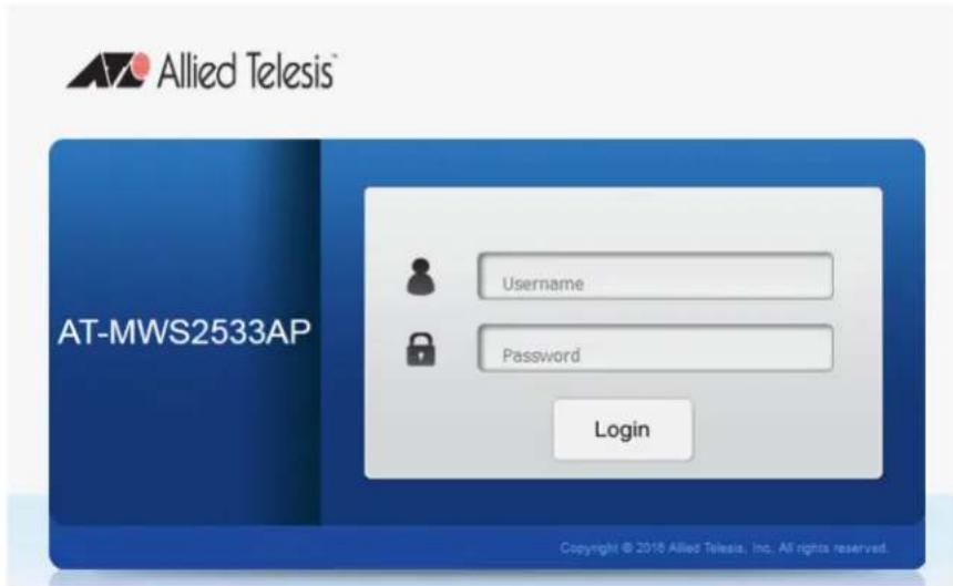
Figure 1. Login Window
- Go to "Starting a Management Session on the Access Point" on page 10.
Starting a Management Session on the Access Point
This section explains how to start a management session on the access point from your management workstation.
To start a management session on the access point, perform the following procedure:
- Open the web browser on your management workstation.
- Enter the IP address of the access point in the URL field of the web browser.
The Login page appears as shown in Figure 1 on page 9.
- Enter the username and password.
The default values are as follow:
– The username: manager
- The password: friend
- Click the Login button.
Saving and Applying Your Changes
The MWS series access point keeps running configuration and startup configuration in one file. When you click the Apply button, your changes are saved into the running/startup configuration file and take effect immediately.
In addition, the access point keeps a temporary configuration file. When you click the Save button, your changes are saved into the temporary configuration file. For your changes to take effect, you must save them to the running/startup configuration file by clicking Change: n button on the top banner and the Apply button.
Applying Your Changes and Saving Them Permanently
To apply your changes immediately and save them into the running/startup configuration files, see the following as an example:
- Make changes on settings. See Figure 2 as an example.
LED Control
| Power | ● Enable ○ Disable |
| LAN | ● Enable ○ Disable |
| WLAN-2.4GHz | ● Enable ○ Disable |
| WLAN-5GHz | ● Enable ○ Disable |
Figure 2. Applying Your Change
- Click the Apply button.
Your changes take effect immediately and are saved to the running/startup configuration file.
Saving Your Changes into a Temporary File
Some pages only offer you the Save button. By clicking the Save button, your changes are saved to the temporary file and not effective. See the following procedure as an example:
- Make changes on settings. See Figure 3 as an example.
Management VLAN Settings
Status
○ Enable ● Disable 4094
Caution: If you encounter disconnection issue during the configuration process, verify that the switch and the DHCP server can support the new VLAN ID and then connect to the new IP address.
Save
Save Current Setting(s)
Figure 3. Saving Your Change
- Click the Save button.
Your changes are saved to the temporary configuration file.
Making Your Changes in the Temporary File Take Effect
To make your changes saved in the temporary file take effect, you must save your changes into the running/startup configuration file. To save the changes into the running/startup configuration file, do the following:
- Open any management Web interface. See Figure 4 as an example.
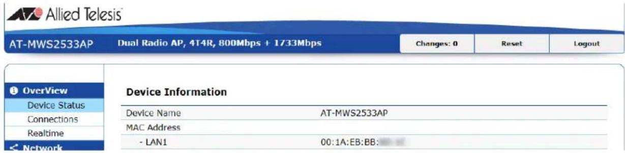
Figure 4. Opening a Web Management Page
- Click the Change: n button on the top banner.
The Configuration / Change page appears as shown in Figure 5.
Note
The n indicates the number of changes that are saved in the temporary configuration file.
Configuration / Changes
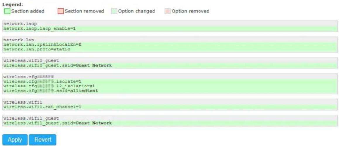
Figure 5. Displaying the Configuration / Change Page
- Click the Apply button.
Your changes take effect and are saved to the running/startup configuration file.
- Or, click the Revert button.
Your changes are discarded.
Chapter 1: Getting Started
Chapter 2
Overview Section
This chapter describes the information in the Overview section. The chapter contains the following sections:
☐ "Displaying the Device Status" on page 16
☐ “Displaying Lists of Connected Clients” on page 24
☐ "Displaying CPU Loading, Traffic, and the Number of Packets" on page 25
Displaying the Device Status
To display the Device Status, select Overview > Device Status from the side bar. the Device Status page includes the following sections:
□ Device Information
□ Memory Information
□ LAN Information - IPv4
□ LAN Information - IPv6
□ Spanning Tree Protocol (STP) Information
☐ Link Aggregation Control Protocol (LACP) Information
☐ Wireless LAN information - 2.4GHz
☐ Wireless LAN information - 5GHz
□ Statistics
Device Information The Device Information section displays information as shown in Figure 6. The fields are defined in Table 1.
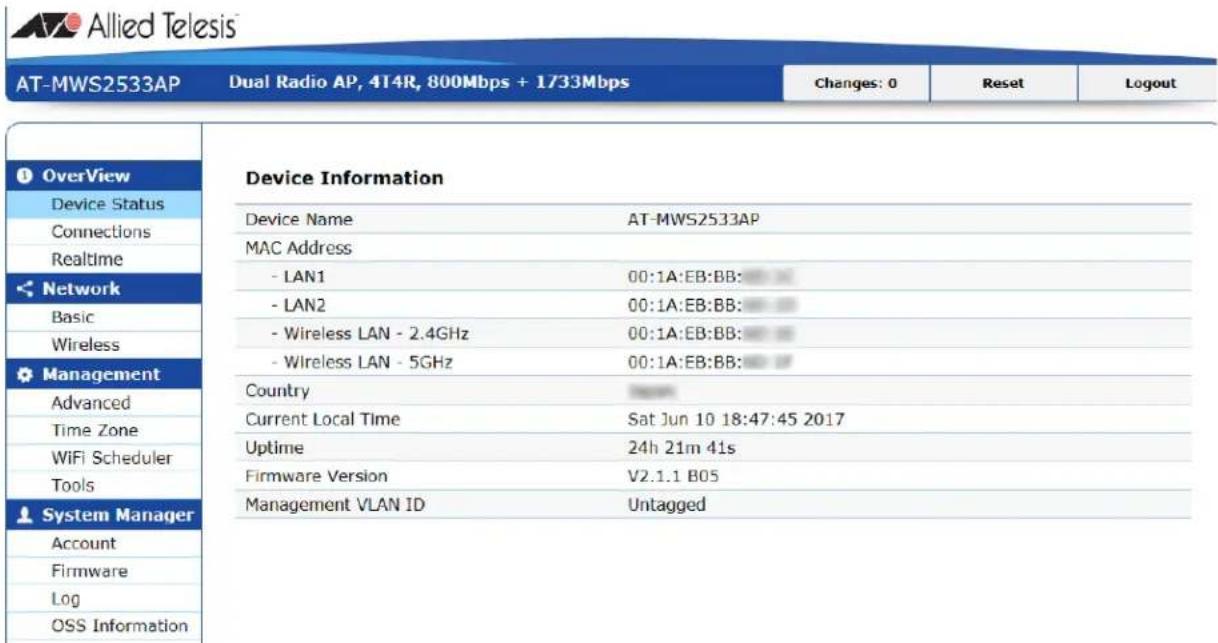
Figure 6. Device Information Section
Table 1. Device Information
| Field Description | |
| Device Name Displays the model name of the device. | |
| MAC Address Displays the MAC addresses of the interfaces. | |
| Country Displays the country code set to the device. | |
| Current Local Time Displays the current time. | |
| Uptime (AT-MWS2533AP model only) | Displays the amount of time since the device was powered on. |
| Firmware Version Displays the version of the firmware that is installed on the device. | |
| Management VLAN ID Displays the management VLAN ID. When it is not specified, it shows “Untagged.” | |
Memory Information
The Memory Information section is only available for the AT-MWS2533AP model.
This section displays information as shown in Figure 7. The fields are defined in Table 2.
Memory Information
| Total Available | 797124 kB / 998276 kB (79%) |
| Free | 758516 kB / 998276 kB (76%) |
| Cached | 20348 kB / 998276 kB (2%) |
| Buffered | 8160 kB / 998276 kB (0%) |
Figure 7. Memory Information Section
Table 2. Memory Information
| Field Description | |
| Total Available Displays the available RAM. | |
| Free Displays the free memory. | |
| Cached Displays the memory used for the cache. | |
| Buffered Displays the memory used for the buffer. | |
LAN Information - IPv4
The LAN Information - IPv4 section displays information as shown in Figure 8. The fields are defined in Table 3.
LAN Information - IPv4
| IP Address | 192.168.1.230 |
| Subnet Mask | 255.255.255.0 |
| Gateway | N/A |
| Primary DNS | N/A |
| Secondary DNS | N/A |
| DHCP Client | Enable |
Figure 8. LAN Information - IPv4 Section
Table 3. LAN Information - IPv4
| Field Description | |
| IP Address Displays the IPv4 address of the device. | |
| Subnet mask Displays the subnet mask of the device. | |
| Gateway Displays the gateway of the device. | |
| Primary DNS Displays the IPv4 address of the primary DNS server. | |
| Secondary DNS Displays the IPv4 address of the secondary DNS server. | |
| DHCP Client Displays whether the DHCP client is enabled or disabled. |
LAN Information - IPv6
The LAN Information -IPv6 section displays information as shown in Figure 9. The fields are defined in Table 4 on page 19.
LAN Information - IPv6
| IP Address | N/A |
| Link-Local Address | N/A |
| Gateway | N/A |
| Primary DNS | N/A |
| Secondary DNS | N/A |
Figure 9. LAN Information - IPv6 Section
Table 4. LAN Information - IPv6
| Field Description | |
| IP Address Displays the IPv6 address of the device. | |
| Link-Local Address Displays the Link-Local IPv6 address of the device. | |
| Gateway Displays the IPv6 gateway of the device. | |
| Primary DNS Displays the IPv6 address of the primary DNS server. | |
| Secondary DNS Displays the IPv6 address of the secondary DNS server. | |
Spanning Tree Protocols (STP) Information
The STP Information section is only available for the AT-MWS2533AP model.
This section displays information as shown in Figure 10. The fields are defined in Table 5.
Spanning Tree Protocol(STP) Information
| Status | Disable | ||
| Hello Time | 2 | ||
| Max Age | 20 | ||
| Forward Delay | 15 | ||
| Priority | 32768 | ||
| Designated Root | 8000.001aebbb6d1c | ||
| Port ID | Port Name | Path Cost | Port Status |
| 8004 | ath0 | 100 | forwarding |
| 8003 | ath1 | 100 | forwarding |
| 8002 | eth0 | 4 | disabled |
| 8001 | eth1 | 4 | forwarding |
Figure 10. Spanning Tree Protocol (STP) Information Section
Table 5. Spanning Tree Protocol (STP) Information
| Field Description | ||
| Status Displays whether STP is enabled or disabled. | ||
| Hello Time Displays | hello time in seconds. The hello time is the interval between Bridge Protocol Data Units (BPDUs) that the root bridge sends out. | |
| Field Description | ||
| Max Age Displays the maximum age time in seconds. The Max Age is the maximum length of time that a bridge port does not receive a BPDU from the root bridge.When the Max Age time is reached, STP starts re-electing a root bridge. | ||
| Forward Delay Displays the forward delay time in seconds. The forward delay time is the time that the root bridge port changes its state from the listening state to the learning state and to the forwarding state. | ||
| Priority Displays the bridge priority of the device. | ||
| Designated Root Displays the bride ID of the device. The bridge ID consists of the bridge priority and MAC address. | ||
| Port Info | Port ID Displays the port ID used in the device. | |
| Port Name Displays the interface name used in the device.☐ ath0 - 2.4GHz interface☐ ath1 - 5GHz☐ eth0 - LAN1☐ eth1 - LAN 2 | ||
| Path Cost Displays the path cost. | ||
| Port Status Displays the port status. | ||
Link Aggregation Control Protocol (LACP) Information
The LACP Information section is only available for the AT-MWS2533AP model.
This section displays information as shown in Figure 11. The fields are defined in Table 6 on page 21.
Link Aggregation Control Protocol (LACP) Information
| Status | Disable |
| Timeout | Long |
| System Priority | 32768 |
| Actor Key | N/A |
| Partner Key | N/A |
| Partner Mac Address | N/A |
Figure 11. Link Aggregation Control Protocol (LACP) Information Section
Table 6. Link Aggregation Control Protocol (LACP) Information
| Field Description | |
| Status Displays whether LACP is enabled or disabled. | |
| Timeout Displays the LACP timeout.☐ Long - The interval of sending LACP packets is set to 30 seconds; the LACP session is set to be 90 seconds.☐ Short - The interval of sending LACP packets is set to 1 second; the LACP session is set to be 3 seconds. | |
| System Priority Displays the LACP system priority. | |
| Actor Key Displays the aggregation key of the device. | |
| Partner Key Displays the aggregation key of the partner device. | |
| Partner Mac Address Displays the MAC address of the partner device. | |
Wireless LAN Information - 2.4GHz
The Wireless LAN Information - 2.4GHz section displays information as shown in Figure 12. The fields are defined in Table 7 on page 22.
Wireless LAN Information - 2.4GHz
| Operation Mode | Access Point | |||
| Wireless Mode | 802.11 B/G/N | |||
| Channel Bandwidth | 20-40 MHz | |||
| Channel | 2.437 GHz(Channel 6) | |||
| Profile | SSID | Security | VID | 802.1Q |
| #1 | allied | None | 1 | Disable |
| #2 | Virtual Access Point 1 | None | 1 | Disable |
| #3 | Virtual Access Point 2 | None | 1 | Disable |
| #4 | Virtual Access Point 3 | None | 1 | Disable |
| #5 | Virtual Access Point 4 | None | 1 | Disable |
| #6 | Virtual Access Point 5 | None | 1 | Disable |
| #7 | Virtual Access Point 6 | None | 1 | Disable |
| #8 | Virtual Access Point 7 | None | 1 | Disable |
| #9 | Guest Network | None | Disable | |
Figure 12. Wireless LAN Information - 2.4GHz Section
Table 7. Wireless LAN Information - 2.4GHz and 5GHz
| Field Description | ||
| Operation Mode Displays the operation mode of the device. | ||
| Wireless Mode Displays the wireless mode. | ||
| Channel Bandwidth Displays the channel bandwidth. | ||
| Channel Displays the frequency and channel number. | ||
| VAP Profile Displays VAP's profile number. | ||
Wireless LAN Information - 5GHz
The Wireless LAN Information - 5GHz section displays information as shown in Figure 13. The fields are defined in Table 7 on page 22.
Wireless LAN Information - 5GHz
| Operation Mode | Access Point | |||
| Wireless Mode | 802.11 N/AC | |||
| Channel Bandwidth | 80 MHz | |||
| Channel | 5.500 GHz(Channel 100) | |||
| Profile | SSID | Security | VID | 802.1Q |
| #1 | allied | None | 1 | Disable |
| #2 | Virtual Access Point 1 | None | 1 | Disable |
| #3 | Virtual Access Point 2 | None | 1 | Disable |
| #4 | Virtual Access Point 3 | None | 1 | Disable |
| #5 | Virtual Access Point 4 | None | 1 | Disable |
| #6 | Virtual Access Point 5 | None | 1 | Disable |
| #7 | Virtual Access Point 6 | None | 1 | Disable |
| #8 | Virtual Access Point 7 | None | 1 | Disable |
| #9 | Guest Network | None | Disable | |
Figure 13. Wireless LAN Information - 5GHz Section
Statistics
The Statistics section displays information as shown in Figure 14. The fields are defined in Table 8.
Statistics
| SSID | MAC | RX(Packets) | TX(Packets) |
| Ethernet | 00:1A:EB:BB:6D:1C | 2.33 MB(22446 Pkts.) | 27.81 MB(49083 Pkts.) |
| allied | 00:1A:EB:BB:6D:1F | 210.30 KB(1442 Pkts.) | 655.56 KB(2057 Pkts.) |
| allied | 00:1A:EB:BB:6D:1F | 257.98 KB(1871 Pkts.) | 840.17 KB(3886 Pkts.) |
Figure 14. Statistics Section
Table 8. Statistics
| Field Description | |
| SSID Displays | the interface name or VAP's SSID. |
| MAC Displays | the MAC address of the interface. |
| RX(Packets) | Displays the total number of the packets that the interface received and total bytes of the packets. |
| TX(Packets) | Displays the total number of the packets that the interface transmitted and total bytes of the packets. |
Displaying Lists of Connected Clients
To display the connected clients, select Overview > Connections from the side bar. the Connections page displays as shown in Figure 15. The fields are defined in Table 9.
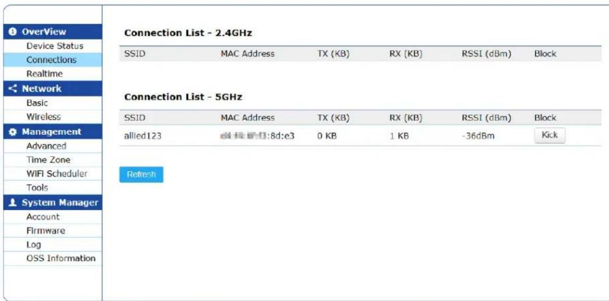
Figure 15. Connections
Table 9. Connections
| Field Description |
| SSID Displays the SSID that the client is connected. |
| MAC Address Displays the MAC address of the client. |
| TX (KB) Displays the data size in bytes that the device sent to the client. |
| RX (KB) Displays the data size in bytes that the device received from the client. |
| RSSI (dBm) Displays the Received Signal Strength Indication (RSSI) of the signal from the client. |
| Block Click the Kick button, it disconnects the client. |
Displaying CPU Loading, Traffic, and the Number of Packets
The Realtime page is only available for the AT-MWS2533AP model.
You can view CPU loading, traffic, and the numbers of packets on the Realtime page.
CPU Loading
To display CPU loading data, select Overview > Realtime from the side bar menu. The CPU loading page displays as shown in Figure 16.
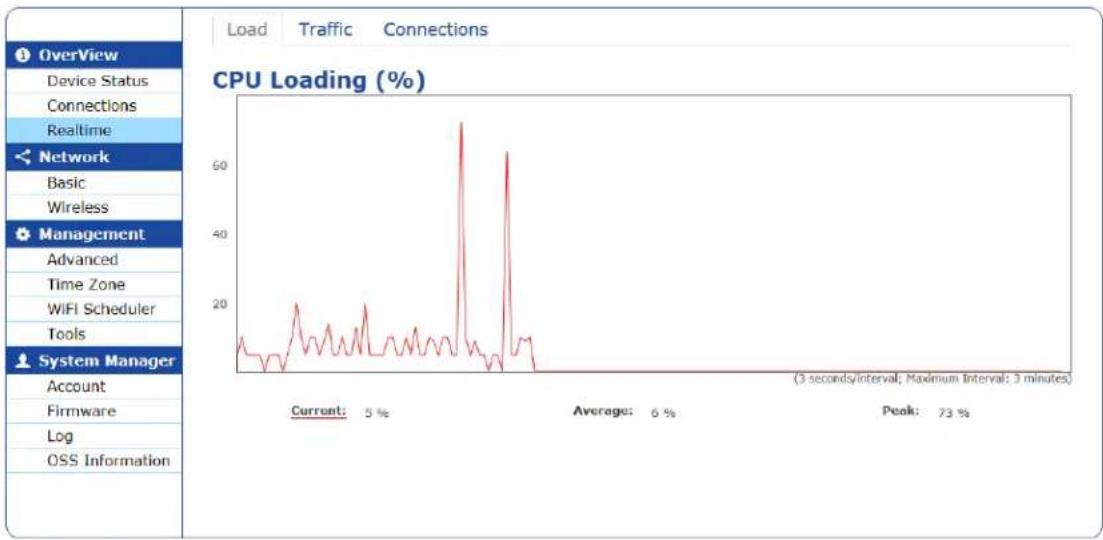
line
| Metric | Value | |--------|-------| | Current: | 5 % | | Average: | 6 % | | Peak: | 73 % |Figure 16. CPU Loading Page
Traffic To display traffic data for SSIDs for 2.4GHz and 5GHz, LAN1, and LAN2 interfaces, select Overview > Realtime from the side bar menu and click the Traffic tab. The Realtime Traffic (KB/s) page displays as shown in Figure 17 on page 26.
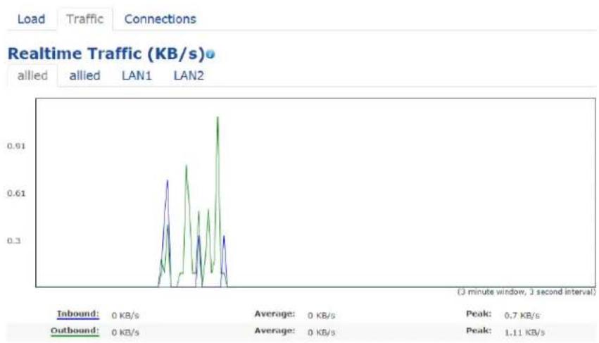
line
| Time | Outbound (KB/s) | Inbound (KB/s) | |------|-----------------|----------------| | Peak | 0.7 | | | Peak | 1.11 | |Figure 17. Realtime Traffic (KB/s) Page
Realtime Connections
To display the numbers of TCP and UDP packets forwarded from the device, select Overview > Realtime from the side bar menu and click the Connections tab. The Realtime Connections (Pkts) page displays as shown in Figure 18 The fields are defined in Table 10 on page 27.
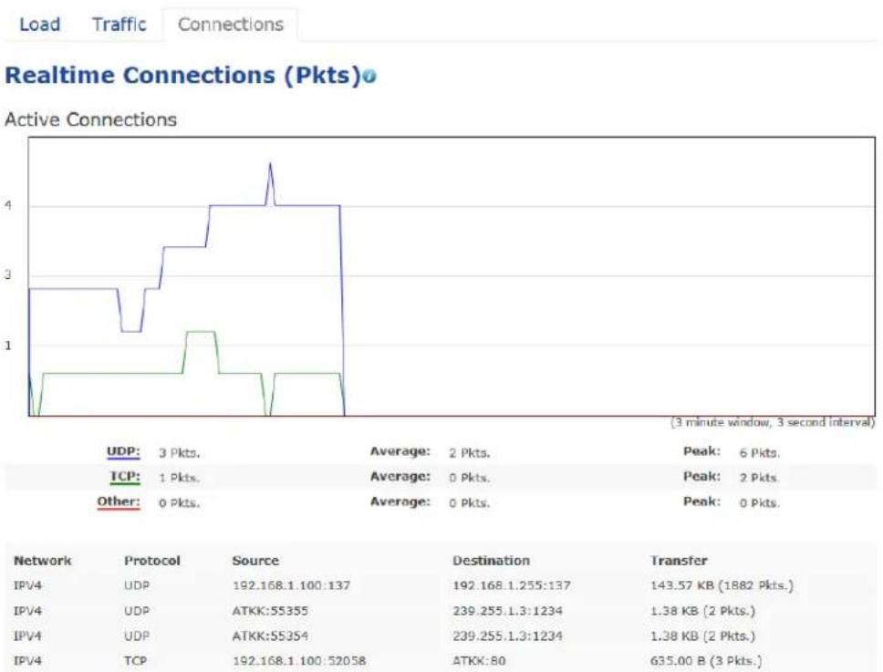
line
Realtime Connections (Pkts) Active Connections | Network | Protocol | Source | Destination | Transfer | | :--- | :--- | :--- | :--- | :--- | | IPV4 | UDP | 192.168.1.100:137 | 192.168.1.255:137 | 143.57 KB (1882 Pkts.) | | IPV4 | UDP | ATKK:55355 | 239.255.1.3:1234 | 1.38 KB (2 Pkts.) | | IPV4 | UDP | ATKK:55354 | 239.255.1.3:1234 | 1.38 KB (2 Pkts.) | | IPV4 | TCP | 192.168.1.100:52058 | ATKX:80 | 635.00 B (3 Pkts.)Figure 18. Realtime Connections Page
Table 10. Connections
| Field Description | |
| Network Displays whether IPv4 or IPv6. | |
| Protocol Displays the protocol:☐ UDP☐ TCP☐ Others - Protocols other than UDP and TCP | |
| Source Displays the IP address and TCP or UDP port of the source. | |
| Destination Displays the IP address and TCP or UDP port of the destination. | |
| Transfer Displays the size of received and transmitted data in kilobytes and the number of received and transmitted packets. |
Chapter 2: Overview Section
Chapter 3
Network Section
This chapter describes the information in the Network section. The chapter contains the following sections:
☐ "Modifying the Basic Settings" on page 30
☐ “Specifying and Modifying Wireless Settings” on page 34
Modifying the Basic Settings
To modify the basic settings for network, select Network > Basic from the side bar. the IPv4 Settings and IPv6 Settings page is displayed.
Note
For your changes to take effect, save your changes by clicking the Save button on a setting page, click the Change: n button on the top banner, and click the Apply button. For more information, see "Saving and Applying Your Changes" on page 11.
IPv4 Settings You can modify the IPv4 settings on the device on the IPv4 Settings section as shown in Figure 19. The fields are defined in Table 11 on page 31.
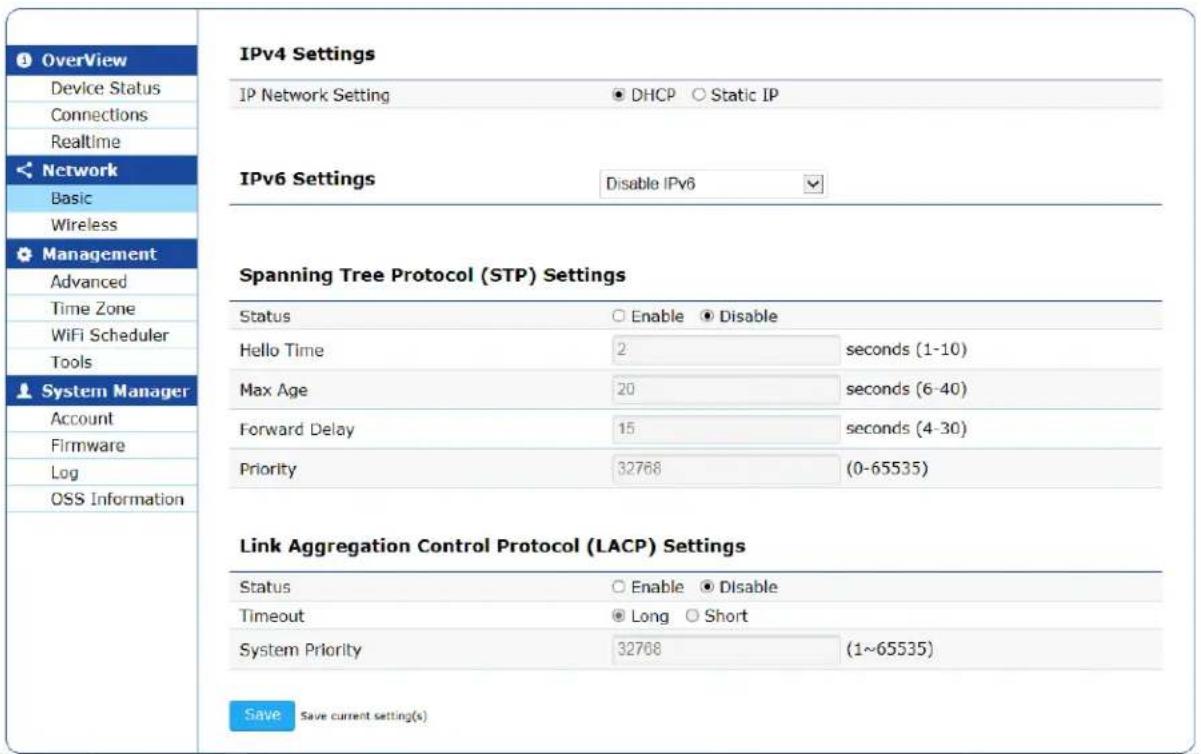
Figure 19. IPv4 Settings and IPv6 Settings Section
Table 11. IPv4 Settings
| Field Description | |
| IP Network Setting S | Specifies IPv4 address assignment either dynamically from a DHCP server or manually. The default setting is DHCP. |
| IP Address Specifies | an IPv4 address when Static IP is selected as the IP Network Setting. The default value is 192.168.1.230. |
| Subnet Mask Specifies | es a subnet mask when Static IP is selected as the IP Network Setting. The default value is 255.255.255.0. |
| Gateway Specifies a | gateway when Static IP is selected as the IP Network Setting. The default value is 192.168.1.1. |
| Primary DNS Specifies | es the IPv4 address of a primary DNS when Static IP is selected as the IP Network Setting. |
| Secondary DNS Spec | ifies the IPv4 address of a secondary DNS when Static IP is selected as the IP Network Setting. |
IPv6 Settings
You can modify the IPv6 settings on the device on the IPv6 Settings section. See Figure 19 on page 30. The fields are described in Table 12
Table 12. IPv6 Settings
| Field Description | |
| IPv6 Settings Specifies | ones one of the following options:☐ Disable IPv6 - This is the default setting.☐ Link-Local address only - a link-local address is assigned.☐ Static IPv6 - manually assign an IPv6 address. |
| IP Address Specifies | an IPv6 address when Static IPv6 is selected. |
| Subnet Prefix Length | Specifies a subnet prefix length when Static IPv6 is selected. |
| Gateway Specifies a | gateway when Static IPv6 is selected. |
| Primary DNS Specifies | es the address of a primary DNS when Static IPv6 is selected. |
| Secondary DNS Specifies the address of a secondary DNS when Static IPv6 is selected. | |
Spanning Tree Protocol (STP) Settings
This section is only available for AT-MWS2533AP model.
You can modify the STP settings in the STP section as shown in Figure 19 on page 30. The fields are defined in Table 13.
Table 13. STP Settings
| Field Description | |
| Status Specifies | whether STP is enabled or disabled. The default setting is disabled. |
| Hello Time Specifies | es hello time in seconds. The range is 1 to 10.The default value is 2 seconds.The hello time is the frequency that the root bridge sends bridge protocol data units (BPDUs). |
| Max Age Specifies | maximum age time in seconds. The range is 6 to 40. The default value is 20 seconds.The Max Age is the maximum length of time that a bridge port waits to receive a BPDU from the root bridge.When the Max Age time is reached, STP starts re-electing a root bridge.Max Age must be determined according to the following formulas:Max Age <= 2 X (forward delay - 1 second)Max Age => 2 X (hello time + 1 second) |
| Forward Delay Specifies | ifies the forward delay time in seconds. The range is 4 to 30 seconds. The default value is 15.The forward delay time is the time that the root bridge port changes its state from the listening state to the learning state and to the forwarding state. |
| Priority Specifies | the bridge priority. The range is 0 to 65535. The default value is 32768. |
Ling Aggregation Control Protocol (LACP) Settings
This section is only available for AT-MWS2533AP model.
You can modify the LACP settings in the LACP section as shown in Figure 19 on page 30. The fields are defined in Table 14.
Table 14. LACP
| Field Description | |
| Status Enable or disable LACP. The default setting is disable. | |
| Timeout Select LACP timeout. The options are:Long - The LACP packet is sent out every 30 seconds.The LACP timeout is 90 seconds.Short - The LACP packet is sent out every second. The LACP timeout is 3 seconds.The default setting is Long. | |
| System Priority | Specify the LACP system priority value. The range is from 1 to 65535. The default value is 32768. |
Specifying and Modifying Wireless Settings
To specify and modify the 2.4GHz and 5GHz settings, select Network > Wireless from the side bar. The Wireless Settings page is displayed as shown in Figure 20. The fields are defined in Table 15.
Note
For your changes to take effect, save your changes by clicking the Save button on a setting page, click the Change: n button on the top banner, and click the Apply button. For more information, see "Saving and Applying Your Changes" on page 11.
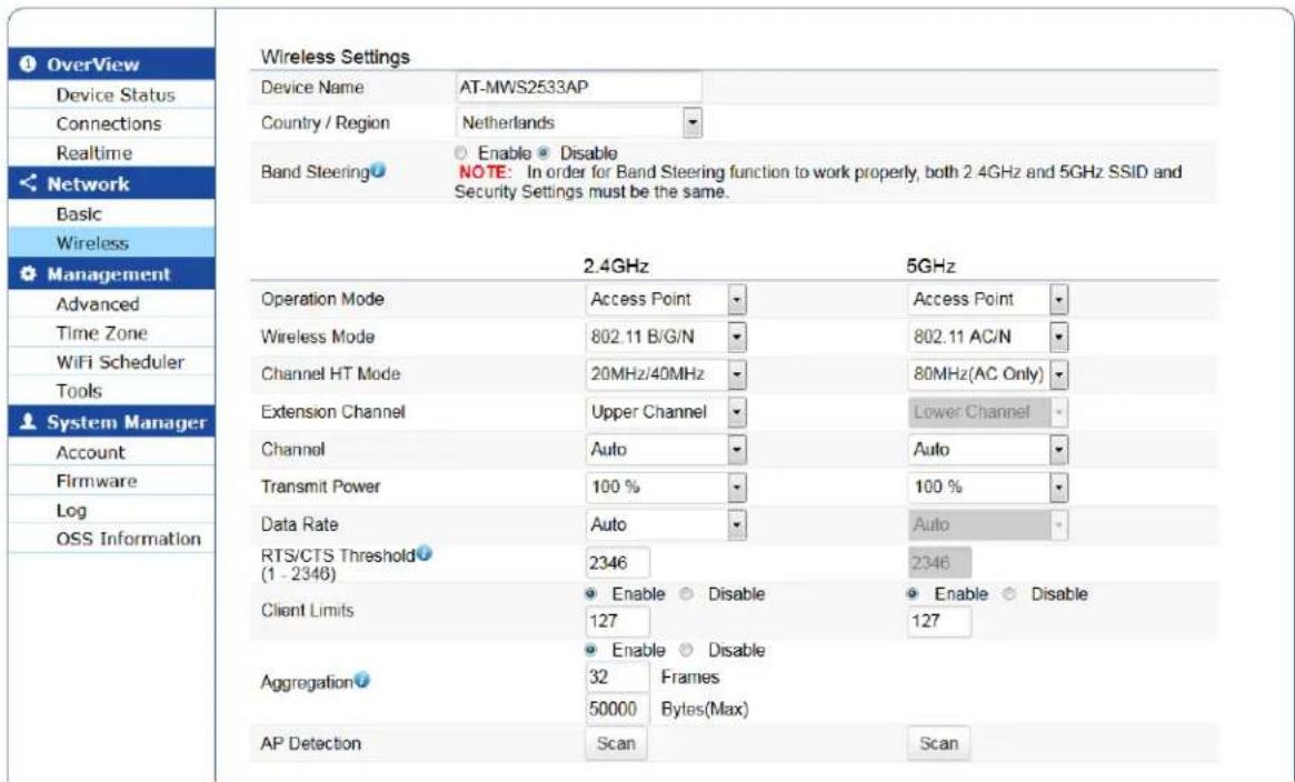
Figure 20. Wireless Settings Page
Table 15. Wireless Settings
| Field Description | ||
| Device Name Assigns a name to the device. The name can have up to 32 alphanumeric characters. The special characters (! $,% ( ) * + , - . <= > ? @ ^ _ { | } ~) are allowed. The device name is used by SNMP managers. | ||
| Country / Region Select the country or region name. If the Country /Region drop-down list is deactivated, the country parameter was set by the manufacturer and cannot be changed. | ||
| NoteContact your Allied Telesis sales representative if the setting is not correct for your country or region. See “Contacting Allied Telesis” on page 5. | ||
| Band Steering Enable or disable Band Steering.When Band Steering is enabled, the device pushes a wireless client to connect the 5GHz network if the client is dual-band capable. The default setting is disable. | ||
| Operation Mode | 2.4GHz Displays the operation mode as “Access Point.” You cannot change the setting. | |
| 5GHz | ||
| Wireless Mode | 2.4GHz Select an IEEE standard to support. | |
| 5GHz | ||
| Channel HT Mode | 2.4GHz Select a channel High Throughput (HT) mode. | |
| 5GHz | ||
| Extension Channel | 2.4GHz Select a extension channel either upper channel or lower channel. The default value is upper channel. | |
| 5GHz You cannot change the value. | ||
| Channel 2.4GHz Select a channel or Auto. When Auto is selected, the system uses the lowest chance to be interfered. The default setting is Auto. | ||
| Transmit Power | 2.4GHz Select the transmit power from 100%, 75%, 50%, 25%, and 10%. The default setting is 100% | |
| Data Rate 2.4GHz Select a date rate. The default setting is Auto. | ||
| RTS/CTS Threshold | 2.4GHz Specify the packet size to determine whether an RTS packet to send. The default value is 2346 bytes. | |
| 5GHz Displays the RTS value. You cannot change it. | ||
Table 15. Wireless Settings (Continued)
| Field Description | |||
| Client Limits 2.4GHz Enable to limit the number of clients or disable not to limit. When it is enabled, specify the number of clients. The range is 1 to 127 clients. By default, limiting the number of clients is enabled and the value is 127. | |||
| Aggregation 2.4GHz Enable or disable Frame Aggregation. When enabled, Frame Aggregation reduces communication overhead to improve throughput by sending multiple frames as one frame. The default setting is enabled. | |||
VAP Settings - 2.4GHz and 5GHz
You can add or modify the settings for the Virtual Access Point (VAP). By collaborating VAPs and VLANs, you can use one physical access point as multiple virtual access points. You can specify up to 8 VAPs for each 2.4GHz and 5 GHz. See Figure 21 on page 37. The fields are defined in Table 16 on page 37.
Wireless Settings - 2.4GHz
| Enabled | SSID | Edit | Security | Hidden SSID | Client Isolation | VLAN Isolation | L2 Isolation | VLAN ID |
| ☑ | allied | Edit | None | ☐ | ☐ | ☐ | ☐ | 1 |
| ☐ | Virtual Access Point 1 | Edit | None | ☐ | ☐ | ☐ | ☐ | 1 |
| ☐ | Virtual Access Point 2 | Edit | None | ☐ | ☐ | ☐ | ☐ | 1 |
| ☐ | Virtual Access Point 3 | Edit | None | ☐ | ☐ | ☐ | ☐ | 1 |
| ☐ | Virtual Access Point 4 | Edit | None | ☐ | ☐ | ☐ | ☐ | 1 |
| ☐ | Virtual Access Point 5 | Edit | None | ☐ | ☐ | ☐ | ☐ | 1 |
| ☐ | Virtual Access Point 6 | Edit | None | ☐ | ☐ | ☐ | ☐ | 1 |
| ☐ | Virtual Access Point 7 | Edit | None | ☐ | ☐ | ☐ | ☐ | 1 |
Wireless Settings - 5GHz
| Enabled | SSID | Edit | Security | Hidden SSID | Client Isolation | VLAN Isolation | L2 Isolation | VLAN ID |
| √ | allied | Edit | None | □ | □ | □ | □ | 1 |
| □ | Virtual Access Point 1 | Edit | None | □ | □ | □ | □ | 1 |
| □ | Virtual Access Point 2 | Edit | None | □ | □ | □ | □ | 1 |
| □ | Virtual Access Point 3 | Edit | None | □ | □ | □ | □ | 1 |
| □ | Virtual Access Point 4 | Edit | None | □ | □ | □ | □ | 1 |
Figure 21. VAP Settings -2.4GHz and 5GHz Section
Table 16. VAP Settings - 2.4GHz and 5GHz
| Field Description | |
| Enabled Enable or disable the VAP. By default, VAP is disabled. | |
| SSID Specify the SSID name for the VAP. The SSID is assigned to the VLAN for this VAP.The SSID name must be alphanumeric characters. The special characters, such as ! “ # $ % & ‘ ( ) * + , - ./ <= > ? @ [ ] ^ _ { | } ~ are allowed. By default, the first SSID is named “allied,” and the rest of the SSID are “Virtual Access Point n.” The n is a number from 1 to 7. | |
| Edit Bring up another page to specify or modify the VAP security, MAC filtering, and Traffic Shaping settings. See “Wireless Security for 2.4GHz and 5GHz” on page 38. | |
| Security Displays the VAP security settings. | |
| Field Description | |
| Hidden SSID Hide or | Broadcast the SSID. When the check box is checked (hide), the SSID is not included in beacon signals. When the check box is not checked, the SSID is included in beacon signals and the SSID is displayed as an available SSID in clients' systems. By default, the Hidden SSID check box is not checked (broadcast). |
| Client Isolation Allow | the clients connected to the same VAP to communicate or deny communication among the clients connected to the same VAP. To allow, uncheck the check box. To deny, check the check box. By default, the check box is not checked (allow). |
| VLAN Isolation Isolate | the VAP traffic only to a specific VLAN or not isolate the VAP traffic. To isolate the VAP traffic, check the check box and assign a VLAN ID. When the check box is not checked, the VAP traffic is not isolated and VLAN 1 is assigned to the VAP. By default, the check box is not checked (not isolated). |
| L2 Isolation Allow the | clients connected to different access points in the same network to communicate or deny these clients to communicate each other. To deny such communication, check the check box. When the L2 Isolation check box is checked (deny), the Client Isolation check box is automatically checked (deny). By default, the check box is not checked (allow). |
| VLAN ID Specify a V | LAN ID. The range is 1 to 4094. The VLAN ID take effect only when VLAN Isolation is activated. The default value is 1. |
Wireless Security for 2.4GHz and 5GHz
When you click the Edit button for the wireless security settings for 2.4GHz and 5Ghz, the Wireless Security, MAC Filter, and Traffic Shaping page appears. see Figure 22. The field is defined in Table 18 on page 40.
Wireless Security - 2.4GHz
| Security Mode | Disabled |
Figure 22. Wireless Security for 2.4GHz and 5GHz Section
Table 17. Wireless Security for 2.4GHz and 5GHz
| Field Description | |
| Security Mode Select one of the following options:□ Disabled - No authentication or encryption□ WEP - Security system using keys. it's considered a weak security system.□ WPA-PSK - Using encryption and authentication between a client and the access point with PSK. (the AT-MWS600AP and AT-MWS1750AP models only)□ WPA2-PSK - Using encryption and authentication between a client and the access point with PSK.□ WPA-PSK Mixed - Using encryption and authentication between a client and the access point with PSK. Applicable to both WPA and WPA2.□ WPA-Enterprise - Using encryption and authentication between a client and the access point with Radius servers. (the AT-MWS600AP and AT-MWS1750AP models only)□ WPA2-Enterprise - Using encryption and authentication between a client and the access point with Radius servers.□ WPA Mixed-Enterprise - Using encryption and authentication between a client and the access point with Radius servers. Applicable to both WPA and WPA2. |
WEP
When you select the WEP from the Security Mode pull-down menu, the following section appears. See Figure 23 on page 40. The fields are defined in Table 18 on page 40.
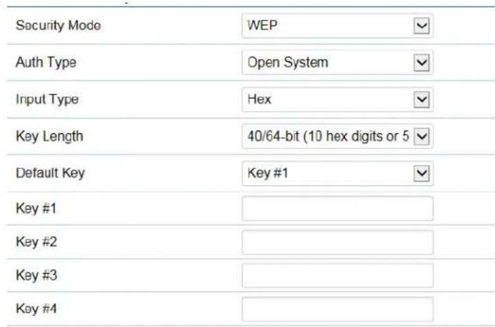
Figure 23. WEP Security Mode
Table 18. WEP Security Mode
| Field Description | |
| Auth Type Select one of the following authentication methods:☐ Open System - A client is allowed to connect to the access point; however, the client must encrypt data with the right WEP key to exchange traffic with the access point.☐ Shared Key - Without the right WEP key, a client is not allowed to connect to the access point.The default setting is Open System. | |
| Input Type Select one of the following key generation methods:☐ Hex - Enter your WEP key in hexadecimal (0 to 9, A to F, and a to f) The key is not case-sensitive.☐ ASCII - Type your WEP key in characters. The key is case-sensitive.Alphanumeric characters including the special characters, such as ! “ # $ % & ‘ () * + , - ./ <= > ? @ [ ] ^ _ { | } ~ are allowed.The default setting is Hex. | |
| Key Length Select one of the following key lengths:☐ 40/64-bit - 10 digits in hexadecimal, 5 characters in ASCII.☐ 104/128-bit - 26 digits in hexadecimal, 13 characters in ASCII.☐ 128/152-bit - 32 digits in hexadecimal, 16 characters in ASCII.The longer key is stronger as a WEP key. The default setting is 40/64-bit. | |
| Default Key Select the key to use from Key #1 to Key #4. You can set up to 4 keys, but only one key is used. The default setting is Key #1. | |
| Key #1 Enter the WE | EP key according to the settings of the Input Type and Key Length. |
| Key #2 | |
| Key #3 | A client must have the same WEP key, which is selected as the Default Key above. |
| Key #4 | |
WPA-PSK, WPA2-PSK, and WPA-PSK Mixed
When you select the WPA-PSK, WPA2-PSK, or WPA-PSK Mixed from the Security Mode pull-down menu, the following section appears. See Figure 24 as an example. The fields are defined in Table 19 on page 42.
Wireless Security - 2.4GHz
| Security Mode | WPA2-PSK |
| Encryption | AES |
| Protected Management Frames | ● Enable ○ Disable |
| Passphrase | |
| Group Key Update Interval | 3600 |
Figure 24. WPA2-PSK Mode
Table 19. WPA-PSK, WPA2-PSK, WPA-PSK Mixed Modes
| Field Description | |
| Encryption AT-MWS | 600AP and AT-MWS1750AP modelsSelect one of the following options:TKIPAESBoth(TKIP+AES)AT-MWS2533AP modelDisplays the encryption protocol. The security mode determines the encryption protocol to use. When the WPA2-PSK security mode is selected, the encryption is set to AES. When the WPA-PSK Mixed security mode is selected, the encryption is set to Both(TKIP+AES). |
| Protected Management Frames | This feature is available only when WPA2-PSK is selected. (on the AT-MWS2533AP or AT-MWS1750AP model)Enable or disable Management Frame Protection (MFP). When MFP is enabled on the access point and the client supports MFP, 802.11 management frames passed between the access point and the client are protected. By default, MFP is enabled. |
| Group Key Update Interval | Specify the interval in seconds between the creation of the new encryption keys that are sent to the clients connected to the VAP. The range is from 30 to 3600 seconds. The default value is 3600 seconds. |
| Passphrase Specify | the encryption key.The passphrase must be from 8 to 64 alphanumeric characters, including the special characters, such as ! “ # $ % & ‘ () * + , - ./ < = > ?@ [ ] ^ _ { | } ~. The passphrase is case-sensitive. |
WPA-Enterprise, WPA2-Enterprise, and WPA Mixed-Enterprise
When you select the WPA-Enterprise, WPA2-Enterprise, or WPA Mixed-Enterprise from the Security Mode pull-down menu, the following section appears. See Figure 25 on page 43 as an example. The fields are defined in Table 20 on page 43.
Wireless Security - 2.4GHz
| Security Mode | WPA2-Enterprise |
| Encryption | AES |
| Protected Management Frames | ● Enable ○ Disable |
| Group Key Update Interval | 3600 |
| Radius Server | |
| Radius Port | 1812 |
| Radius Secret | |
| Radius Accounting | Disable |
| Radius Accounting Server | |
| Radius Accounting Port | 1813 |
| Radius Accounting Secret | |
| Interim Accounting Interval | 600 |
Figure 25. WPA2-Enterprise
Table 20. WPA-Enterprise, WPA2-Enterprise, WPA Mixed-Enterprise
| Field Description | |
| Encryption AT-MWS | 600AP and AT-MWS1750AP modelsSelect one of the following options:☐ TKIP☐ AES☐ Both(TKIP+AES)AT-MWS2533AP modelDisplays the encryption protocol. The security mode determines the encryption protocol to use. When the WPA2-Enterprise security mode is selected, the encryption is set to AES. When the WPA Mixed-Enterprise security mode is selected, the encryption is set to Both(TKIP+AES). |
Table 20. WPA-Enterprise, WPA2-Enterprise, WPA Mixed-Enterprise
| Field Description | |
| Protected Management Frames | This feature is available only when WPA2-Enterprise is selected. (on the AT-MWS2533AP or AT-MWS1750AP model)Enable or disable Management Frame Protection (MFP). When MFP is enabled on the access point and the client supports MFP, 802.11 management frames passed between the access point and the client are protected. By default, MFP is enabled. |
| Group Key Update Interval | Specify the interval in seconds between the creation of the new encryption keys that are sent to the clients connected to the VAP. The range is from 30 to 3600 seconds. The default value is 3600 seconds. |
| Radius Server Specify the IP address of the RADIUS server. | |
| Radius Port Specify the UDP port number for the RADIUS server. The range is 0 to 65535. The default value is 1812. | |
| Radius Secret Specify the password to connect to the RADIUS server. The password must be 1 to 64 alphanumeric characters. | |
| Radius Accounting Enable or disable RADIUS Accounting. When it is enabled, information about network usage is logged. By default, RADIUS Accounting is disabled. | |
| Radius Accounting Server | Specify the IP address of the RADIUS Accounting server. |
| Radius Accounting Port | Specify the UDP port number for the RADIUS Accounting server. The range is 0 to 65535. The default value is 1813. |
| Radius Accounting Secret | Specify the password to connect to the RADIUS Accounting server. The password must be 1 to 64 alphanumeric characters. |
| Radius Accounting Interval | Specify the interval in seconds between sending data to the RADIUS Accounting server. The range is from 60 to 600 seconds. The default value is 600 seconds. |
Fast Roaming When you edit the security mode for SSID 1 for 2.4GHz or 5GHz and select the security mode WPA2-Enterprise, or WPA Mixed-Enterprise, you can enable or disable Fast Roaming. See Figure 26. The fields are defined in Table 21.
Fast Roaming
Enable Fast Roaming

Enable

Disable
Figure 26. Fast Roaming Section
Table 21. Fast Roaming
| Field Description | |
| Enable Fast Roaming | Enable or disable Fast Roaming. When a client is roaming, the access points exchange information without authenticating the client from the RADIUS server. Fast Roaming reduces time for a wireless phone using VoIP to disconnect.By default, Fast Roaming is disabled. |
Wireless MAC Filter for 2.4GHz and 5GHz
When you edit the security mode, you can also add security using the MAC addresses of clients. Figure 27. The fields are defined in Table 22.

Figure 27. MAC Filter for 2.4GHz and 5GHz Section
Table 22. MAC Filter for 2.4GHz and 5GHz
| Field Description | |
| ACL Mode Select | one of the following options:☐ Disabled - Disable MAC Filtering.☐ Deny MAC in the List - Denies access form clients with the MAC addresses on the list.☐ Allow MAC in the List - Allow clients with the MAC addresses on the list to access the access point.. |
| MAC Address Enter a MAC address. | |
| Add button Click the Add button to add the MAC address to the list. | |
| No. and MAC Address | Displays a list of the added MAC addresses and the list number. |
Wireless Traffic Shaping for 2.4GHz and 5GHz
When you edit the security mode, you can also control communication rates between the access point and clients. Figure 28. The fields are defined in Table 23.
| Wireless Traffic Shaping | ||
| Enable Traffic Shaping | ○ Enable ● Disable | |
| Download Limit | 100 Mbps (1-999) | □ Per User |
| Upload Limit | 100 Mbps (1-999) | □ Per User |
Figure 28. Wireless Traffic Shaping for 2.4GHz and 5GHz Section
Table 23. Wireless Traffic Shaping for 2.4GHz and 5GHz
| Field Description | |
| Enable Traffic Shaping | Enable or disable Traffic Shaping. By default, Traffic Shaping is disabled. |
| Download Limit Specify the maximum communication rate from the access point to a client. The range is 1 to 999 Mbps. The default value is 100 Mbps. | |
| Upload Limit Specify the maximum communication rate from a client to the access point. The range is 1 to 999 Mbps. The default value is 100 Mbps. | |
Guest Network Settings
In addition to private SSID, you can create up to two guest networks. See Figure 29. The fields are defined in Table 24.
Guest Network Settings
| Enabled | SSID | Edit | Security | Hidden SSID | Client Isolation |
| □ | Guest Network | Edit | None | □ | □ |
| □ | Guest Network | Edit | None | □ | □ |
| Manual IP Settings | |||||
| - IP Address | 192.168.200.1 | ||||
| - Subnet Mask | 255.255.255.0 | ||||
| Automatic DHCP Server Settings | |||||
| - Starting IP Address | 192.168.200.100 | ||||
| - Ending IP Address | 192.168.200.200 | ||||
| - WINS Server IP | 0.0.0.0 | ||||
Figure 29. Guest Network Settings
Table 24. Guest Network Settings
| Field Description | |
| Enabled Enable or disable the guest network. By default,the guest network is disabled. | |
| SSID Specify the SSID name for the guest network.The SSID name must be alphanumeric characters. The special characters, such as ! “ # $ % & ‘ ( ) * + , - ./ <= > ? @ [ ] ^ _ { | } ~ are allowed. By default, guest network SSIDs are “Guest Network.” | |
| Edit Bring up another page to specify or modify the VAP security setting. See “Wireless Security for 2.4GHz and 5GHz” on page 38. | |
| Security Displays the VAP security settings. | |
| Hidden SSID Hide or Broadcast the guest network SSID.When the check box is checked (hide), the SSID is not included in beacon signals. When the check box is not checked, the SSID is included in beacon signals. The SSID is displayed as an available SSID in clients’ systems. By default, the Hidden SSID check box is not checked (broadcast). | |
| Client Isolation Allow | the clients connected to the same guest network VAP to communicate or deny communication among the clients connected to the same guest network VAP. To allow, uncheck the check box. To deny, check the check box.The default settings are:☐ Disabled on the AT-MWS2533AP model.☐ Enabled on the AT-MWS600AP and AT-MWS1750AP models. |
| Manual IP Settings | |
| - IP Address Specify | the IPv4 address for the guest network.The default IPv4 address is 192.168.200.1. |
| - Subnet Mask Specify | the subnet mask for the guest network.The default subnet mask is 255.155.255.0. |
| Automatic DHCP Server Settings | |
| - Starting IP Address | Specify the smallest IPv4 address among the IPv4 addresses that the access point lends to clients. The default starting IPv4 address is 192.168.200.100. |
| - Ending IP Address | Specify the largest IPv4 address among the IPv4 addresses that the access point lends to clients.The default ending IPv4 address is 192.168.200.200. |
| - WINS Server IP Specify | specify the IPv4 address of the WINS server when IPv4 address is assigned to the client's NetBIOS name. The default IPv4 address is 0.0.0.0. |
Wireless Security for The Guest Network
When you click the Edit button for the wireless security settings for the Guest Network, the Wireless Security page appears. To change the security mode, see Figure 30. The field is defined in Table 25 on page 49.
Wireless Security - 2.4GHz
| Security Mode | Disabled |
Figure 30. Wireless Security for Guest Network Page
Table 25. Wireless Security for Guest Network
| Field Description | |
| Security Mode Select one of the following options:□ Disabled - No authentication or encryption□ WPA-PSK - Using encryption and authentication between a client and the access point with PSK. (the AT-MWS600AP and AT-MWS1750AP models only)□ WPA2-PSK - Using encryption and authentication between a client and the access point with PSK.□ WPA-PSK Mixed - Using encryption and authentication between a client and the access point with PSK. Applicable to both WPA and WPA2. | |
WPA-PSK, WPA2-PSK, and WPA-PSK Mixed
When you select the WPA-PSK, WPA2-PSK, or WPA-PSK Mixed from the Security Mode pull-down menu, the following section appears. See Figure 31. The fields are defined in Table 26 on page 50.
Wireless Security - 2.4GHz
| Security Mode | WPA2-PSK |
| Encryption | AES |
| Protected Management Frames | ● Enable ○ Disable |
| Passphrase | |
| Group Key Update Interval | 3600 |
Figure 31. WPA2-PSK Security Mode for Guest Network
Table 26. WPA2-PSK Security Mode for Guest Network
| Field Description | |
| Encryption AT-MWS | 600AP and AT-MWS1750AP modelsSelect one of the following options:☐ TKIP☐ AES☐ Both(TKIP+AES)AT-MWS2533AP modelDisplays the encryption protocol. The security mode determines the encryption protocol to use. When the WPA2-PSK security mode is selected, the encryption is set to AES. When the WPA-PSK Mixed security mode is selected, the encryption is set to Both(TKIP+AES). |
| Passphrase Specify | the encryption key.The passphrase must be from 8 to 64 alphanumeric characters, including the special characters, such as ! “ # $ % & ‘ ( ) * + , - ./ <= >? @ [ ] ^ _ { | } ~. The passphrase is case-sensitive. |
| Group Key Update Interval | Specify the interval in seconds between the creation of the new encryption keys that are sent to the clients connected to the VAP. The range is from 30 to 3600 seconds. The default value is 3600 seconds. |
RSSI Threshold (Fast Handover)
You can enable or disable Fast Handover and specify RSSI value. See Figure 32. The fields are defined in Table 27 on page 51.

Figure 32. RSSI Threshold Section
Table 27. RSSI Threshold
| Field Description | |
| Status Enable or disable Fast Handover. By default,Fast Handover is disabled. | |
| RSSI Specify the RSSI (Received Signal StrengthIndication) threshold. The range is -60 to -90 dBm. The default value is -70 dBm. | |
Management VLAN Settings
You can set the management VLAN from the Management VLAN Settings page as shown in Figure 33. The fields are defined in Table 28 on page 51.
Management VLAN Settings
Status ○ Enable ● Disable 4094
Caution: If you encounter disconnection issue during the configuration process, verify that the switch and the DHCP server can support the new VLAN ID and then connect to the new IP address.
Figure 33. Management VLAN Settings Section
Table 28. Management VLAN Settings
| Field Description | |
| Status Enable or disable Management VLAN. When it is enabled, the access point uses the specified VLAN as the management tagged VLAN. By default, Management VLAN is disabled (untagged VLAN). | |
| VLAN ID Specify the | VLAN ID for the management VLAN.The range is 1 to 4094. |
Chapter 3: Network Section
Chapter 4
Management Section
This chapter describes the management functions of the menu selections in the Manage menu. The chapter contains the following sections:
☐ “Specifying Management Settings” on page 54
☐ “Specifying Date, Time, and Time Zone Settings” on page 60
☐ “Specifying Auto Reboot Setting and Wi-Fi Scheduler” on page 62
☐ "Using the Management Tools" on page 64
Specifying Management Settings
To mange the Controller, SNMP, HTTPS, or Email alert, select Management > Advanced from the side bar as shown in Figure 34.
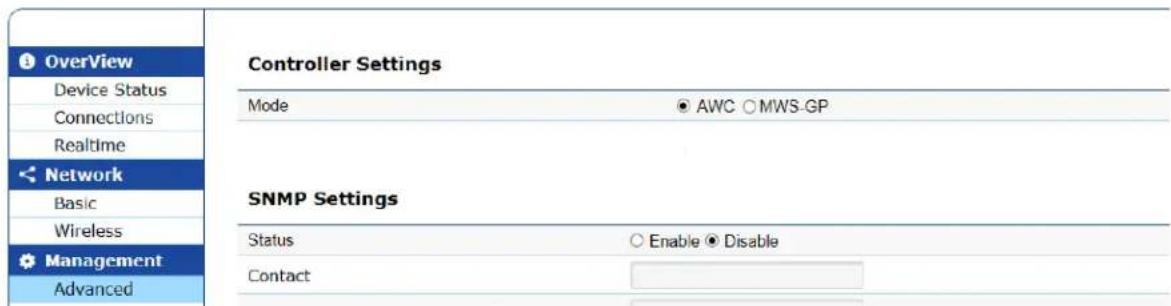
Figure 34. Management Advanced Page
Sections Not Supported
The following sections on the Management > Advanced page are not supported:
□ CLI Setting
□ SSH Setting
Controller Settings
You can view the Controller settings as shown in Figure 35. The fields are defined in Table 29.
Controller Settings
| Mode | AWC ○ MWS-GP |
Figure 35. Controller Settings
Table 29. Controller Settings
| Field Description |
| Mode Indicates that the wireless controller mode is AWC.You cannot change the setting.AWC - Allows the AWC plug-in by the AT-Vista Manager EX to manage the access point.MWS-GP - Not available. |
SNMP Settings
You can specify or modify the SNMP settings in the SNMP settings section as shown in Figure 36 on page 55. The fields are defined in Table 30 on page 56.
SNMP Settings
| Status | ○ Enable ● Disable | |
| Contact | ||
| Location | ||
| Port | 161 | |
| Community Name (Read Only) | public | |
| Community Name (Read Write) | private | |
| Trap Destination | ||
| - Port | 162 | |
| - IP Address | ||
| - Community Name | public | |
| SNMPv3 Settings | ||
| - Status | ○ Enable ● Disable | |
| - Username | admin | (1-31 Characters) |
| - Authorized Protocol | MD5 | |
| - Authorized Key | 12345678 | (8-32 Characters) |
| - Private Protocol | DES | |
| - Private Key | 12345678 | (8-32 Characters) |
| - Engine ID | ||
Figure 36. SNMP Section
Table 30. SNMP Settings
| Field Description | ||
| Status Specifies the SNMP | agent enabled or disabled. The default setting is disable. | |
| Contact Assigns a system administrator name (the MIB object sysContact). The Contact can have 1 to 255 alphanumeric characters. The space and special characters, such as ! “ # % & ‘ ( ) * + , - ./ < = > ? @ [ ] ^ “ _ | ~ are allowed. The name is case-sensitive. | ||
| Location Assigns a system administrator name (the MIB object sysLocation). The Location can have 0 to 255 alphanumeric characters. The space and special characters, such as ! “ # % & ‘ ( ) * + , - ./ < = > ? @ [ ] ^ “ _ { | } ~ are allowed. The name is case-sensitive. | ||
| Port Specifies the SNMP listening UDP port number. The value can be 1 to 65535. The default value is 161. | ||
| Community Name (Read Only) | Specifies the read-only community name. The name can have 1 to 32 alphanumeric characters. The space and special characters, such as ! “ # % & ‘ ( ) * + , - ./ < = > ? @ [ ] ^ “ _ | ~ are allowed. The name is case-sensitive. The default name is public. | |
| Community Name (Read Write) | Specifies the write-read community name. The name can have 1 to 32 alphanumeric characters. The space and special characters, such as ! “ # % & ‘ ( ) * + , - ./ < = > ? @ [ ] ^ “ _ { | } ~ are allowed. The name is case-sensitive. The default name is private. | |
| Trap Destination | Port Specifies the UDP port number to send traps to. The port number can be 1 to 65535. The default value is 162. | |
| IP Address S | Specifies the IP address of a trap host. | |
| Community Name | Specifies the name of the community to send traps. The name can have 1 to 32 alphanumeric characters. The space and special characters, such as ! “ # % & ‘ ( ) * + , - ./ < = > ? @ [ ] ^ “ _ | ~ are allowed. The name is case-sensitive. The default name is public. | |
| SNMPv3 Settings | Status Select | enable of disable:☐ Enable - enables SNMPv3☐ Disable - enables SNMPv1/v2c |
| Username S | Specifies the SNMPv3 username. The username can have 1 to 31 alphanumeric characters. The space and special characters, such as ! “ # % & ‘ ( ) * + , - ./ < = >? @ [ ] ^ “ _ { | } ~ are allowed. The name is case-sensitive. The default name is admin. | |
| Authorized Protocol | Select an authorized protocol:☐ MD5 - Requires to set the following Authorized Key, Private Protocol, and Private Key. This is the default value for the AT-MWS2533AP model.☐ SHA - Requires to set the following Authorized Key, Private Protocol, and Private Key.☐ None - No authorization. This is the default value for the AT-MWS600AP and AT-MWS1750AP models. | |
| Authorized Key | Specifies the authorization password. The password can have 8 to 32 alphanumeric characters. The space and special characters, such as ! “ # % & ‘ ( ) * + , - ./ < = > ? @ [ ] ^ “ _ | ~ are allowed. The password is case-sensitive. The default password is 12345678. | |
| Private Protocol | Select the encryption protocol:☐ DES- Requires to set the following Private Key. This is the default value for the AT-MWS2533AP model.☐ None - No encryption. This is the default value for the AT-MWS600AP and AT-MWS1750AP models. | |
| Private Key | Specifies the encryption password. The password can have 8 to 32 alphanumeric characters. The space and special characters, such as ! “ # % & ‘ ( ) * + , - ./ < = >? @ [ ] ^ “ _ | ~ are allowed. The password is case-sensitive. The default name is 12345678. | |
| Engine ID S | Specifies the SNMP engine ID. The ID can have 0 to 32 alphanumeric characters. The space and special characters, such as ! “ # % & ‘ ( ) * + , - ./ < = > ? @ [ ]^ “ _ { | } ~ are allowed. The engine ID is case-sensitive. | |
HTTPS Settings
You can specify or modify the HTTPS settings in the HTTPS settings section as shown in Figure 37. The field definitions are described in Table 31.
HTTPS Settings
| Status | ○ Enable ● Disable |
| HTTPS Forward | ○ Enable ● Disable |
Figure 37. HTTPS Settings
Table 31. HTTPS Settings
| Field Description | |
| Status Specifies | the HTTPS server enabled or disabled. The default setting is disable. |
| HTTPS Forward | Specifies the HTTPS forwarding enabled or disabled:☐ Enable - When a user access using HTTP, the system displays a screen using HTTPS.☐ Disable - When a user access using HTTP, the system displays a screen using HTTP. |
Email Alert You can enable or disable the email alert function and specify email information in the Email Alert section as shown in Figure 38. The field definitions are described in Table 32 on page 59.
Email Alert
| Status | Enable | |
| - From | ||
| - To | ||
| - Subject | [Email-Alert][AT-MWS2533AP] | |
| Email Account | ||
| - Username | ||
| - Password | # | |
| - SMTP Server | Port: 25 | |
| - Security Mode | None | Send Test Mail |
Apply
Apply saved settings to take effect
Figure 38. Email Alert
Table 32. Email Alert
| Field Description | ||
| Status Status Enable or disable receiving alert messages via e-mail. The default setting is disable. | ||
| Subject Specify the subject line of the alert messages.The default setting is “[Email-Alert] device_model_name device_MAC_address Configuration Changed.” | ||
| Email Account | Username Specify the account (username) of the SMTP server that sends alert messages. | |
| Password Specify the password for the account of the SMTP server that sends alert messages. The green two arrows button is a toggle-key, which enables or disables password display. | ||
| SMTP Server Specify the IP address of the SMTP server that sends alert messages. | ||
| Port Specify the port number of the SMTP server. The range is 1 to 65535. The default value is 25. (25 means the Security Mode set “None.”) | ||
| Security Mode | Select the encryption mode that the SMTP server uses when sending alert messages:☐ SSL/TLS - SSL/TLS encryption☐ STARTTLS - The system first checks whether the SMTP server supports SSL/TLS. If the SMTP supports SSL/TLS, the system uses encryption.☐ None - This is the default value. | |
| Send Test Mail | To test the all the email settings work, click the Send Test Mail button. | |
Specifying Date, Time, and Time Zone Settings
To specify the date and time, select Management > Time Zone from the side bar.
Note
For your changes to take effect, save your changes by clicking the Save button on a setting page, click the Change: n button on the top banner, and click the Apply button. For more information, see "Saving and Applying Your Changes" on page 11.
Date and Time Settings
You can specify or modify the date and time on the system from the Date and Time Settings page as shown in Figure 39. The fields are defined in Table 33 on page 61.
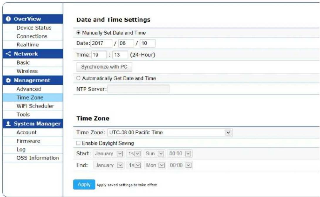
Figure 39. Date, Time, and Time Zone Settings Page
Table 33. Date and Time Settings
| Field Description | |
| Manually Set Date and Time | Turn on the radio button to set date and time manually. When selecting the manual setting, fill the date and time. |
| Date Specify year | , month, and day. |
| Time Specify time. | |
| Synchronize with PC | Click the Synchronize with PC button to set the date and time by synchronizing with the management PC. |
| Automatically Get Date and Time | Turn on the radio button to get date and time automatically from an NTP server. When selecting the automatic setting, specify the NTP server. |
| NTP Server Specify the IP address or host name (FQDN) of the NTP server. | |
Time Zone You can view the time zone set on your device on the Time Zone section as shown in Figure 39 on page 60. The fields are defined in Table 34.
Table 34. Time Zone
| Field Description | |
| Time Zone Select your time zone. | |
| Enable Daylight Saving | Enable or disable to adjust the clock for Daylight Saving Time. |
Specifying Auto Reboot Setting and Wi-Fi Scheduler
To specify the Auto Reboot and Wi-Fi Scheduler, select Management > Wi-Fi Scheduler from the side bar.
Note
For your changes to take effect, save your changes by clicking the Save button on a setting page, click the Change: n button on the top banner, and click the Apply button. For more information, see "Saving and Applying Your Changes" on page 11.
Auto Reboot Settings
You can enable or disable the automatic rebooting function on the Auto Reboot Settings section as shown in Figure 40. The fields are defined in Table 35.
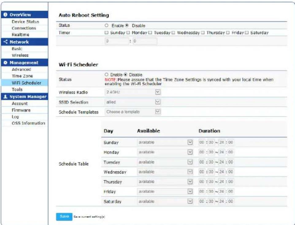
Figure 40. Auto Reboot and Wi-Fi Scheduler Settings Page
Table 35. Auto Reboot Settings
| Field Description | |
| Status Enable or | disable the automatic rebooting function.When this function is enabled. the system reboots at the specified time on the specified days of the week. |
| Timer Select days | of the week and time of the day when the system reboots. |
Wi-Fi Scheduler
You can enable or disable Wi-Fi Scheduler and specify the scheduling on the Wi-Fi Scheduler section as shown in Figure 40 on page 62. The fields are described in Table 36.
Table 36. Wi-Fi Scheduler
| Field Description | |
| Status Enable or disable | VAP access scheduling. The default setting is disable. |
| Wireless Radio Select | the radio, 2.4GHz or 5Hz. |
| SSID Selection Select | an SSID to be scheduled from the list. |
| Schedule Templates Select | a schedule template if using a schedule table for scheduling. |
| Schedule Table Specify | the available or unavailable VAP access time each day. |
Using the Management Tools
The common network tools are available on the Tools page. To use thees tools, select Management > Tools from the side bar.
Ping Test Parameters
You can use ping command on the Ping section as shown in Figure 41. The fields are defined in Table 37.
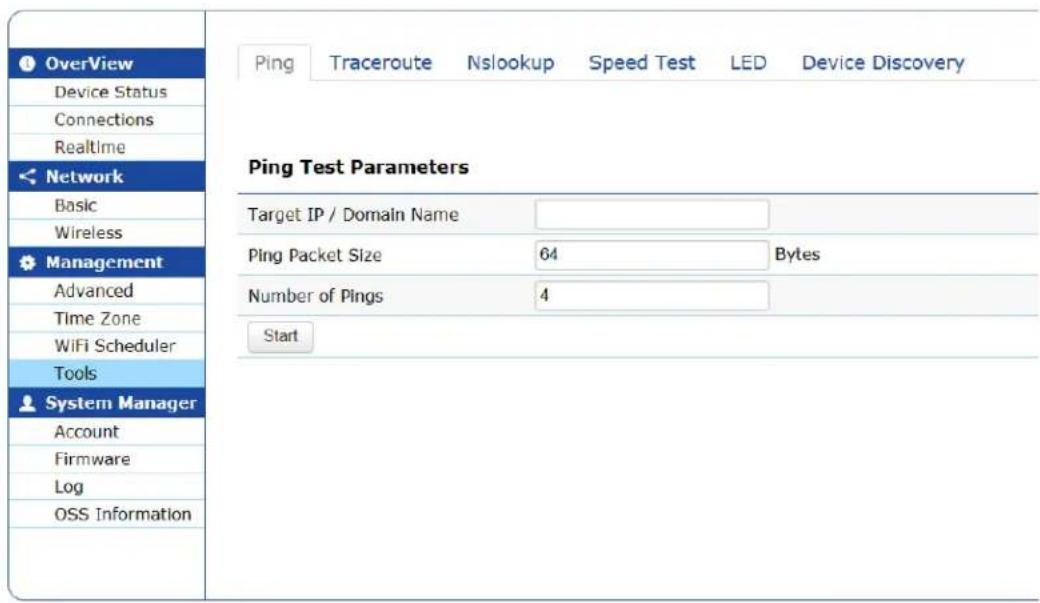
Figure 41. Ping Test Parameters Page
Table 37. Ping Test Parameters
| Field Description | |
| Target IP / Domain Name | Specify the IP address or host name of the target to query. |
| Ping Packet Size | Specify the length of a query packet. The range is 64 to 20480 bytes. The default value is 64 bytes. |
| Number of Pings | Specify how many times to send query packets. The range is 1 to 9999 times. The default value is 4 times. |
| Start Click the Start button to execute the ping command. | |
Traceroute Test Parameters
To use traceroute command, go to Management > Tools and click the Tracerout tab. See Figure 41. The fields are defined in Table 40 and Table 38.
Traceroute Test Parameters

Figure 42. Traceroute Test Parameters
Table 38. Traceroute Test Parameters
| Field Description | |
| Target IP / Domain Name | Specify the IP address or host name of the target to trace the route. |
| Start Click the Start button to execute the traceroute command. Click the Stop button to stop the command. | |
Nslookup Test Parameters
This section is only available for the AT-MWS2533AP model.
To use Nslookup command, go to Management > Tools and click the Nslookup tab. See Figure 43. The fields are defined in Table 39.
Nslookup Test Parameters

Figure 43. Nslookup Test Parameters Page
Table 39. Nslookup Test Parameters
| Field Description | |
| Target IP / Domain Name | Specify the IP address or host name of the target to query the Domain Name System (DNS). |
| Start Click the Start button to execute the nslookup command. | |
Speed Test Parameters
To test the speed, go to Management > Tools and click the Speed Test tab. See Figure 44. The fields are defined in Table 40.
Speed Test Parameters
| Target IP / Domain Name | ||
| Time Period | 20 | Sec |
| Check Interval | 5 | Sec |
| IPv4 Port | 5001 | |
| IPv6 Port | 5002 | |
| Start | ||
Figure 44. Speed Test Parameters Page
Table 40. Speed Test Parameters
| Field Description | |
| Target IP / Domain Name | Specify the IP address or host name of the target to test the speed. |
| Time Period Specify the amount of time to test the speed in seconds. The range is 1 to 9999 seconds. The default value is 20 seconds. | |
| Check Interval Specify the interval of the tests in seconds. The range is 1 to 9999 seconds. The default value is 5 seconds. | |
| Start Click the Start button to star the speed test. | |
| IPv4 Port Displays the TCP/UDP port number for the IPv4 test.You cannot change the value. | |
| IPv6 Port Displays the TCP/UDP port number for the IPv6 test.You cannot change the value. | |
LED Control To control LED, go to Management > Tools and click the LED tab. See Figure 45. The fields are defined in Table 41 on page 67.
LED Control
| Power | ● Enable ○ Disable |
| LAN | ● Enable ○ Disable |
| WLAN-2.4GHz | ● Enable ○ Disable |
| WLAN-5GHz | ● Enable ○ Disable |
Apply
Apply saved settings to take effect
Figure 45. LED Control Page
Table 41. LED Control
| Field Description | |
| Power Enable | or disable the Power LED. When enabled, the LED indicates the status. When disabled, the LED is off. |
| LAN Enable or | disable the LAN LED. When enabled, the LED indicates the status. When disabled, the LED is off. |
| WLAN-2.4GHz | Enable or disable the 2.4GHz LED. When enabled, the LED indicates the status. When disabled, the LED is off. |
| WLAN-5GHz | Enable or disable the 5GHz LED. When enabled, the LED indicates the status. When disabled, the LED is off. |
| Apply Click the | Apply button to take effect. |
Device Discovery
To discover other AT-MWS series access points, go to Management > Tools and click the Device Discovery tab. See Figure 46. The fields are defined in Table 42.
Device Discovery
| Device Name | Operation Mode | IP Address | System MAC Address | Firmware Version |
| Scan |
Figure 46. Device Discovery
Table 42. Device Discovery
| Field Description | |
| Device Name Dis | plays the device name of the detected access point. |
| Operation Mode | Displays the operation mode of the detected access point. |
| IP Address Dis | ays the IP address of the detected access point. |
| System MAC Address | Displays the MAC address of the detected access point. |
| Firmware Version | Displays the version of the firmware that the detected access point |
| Scan Click the S | can button to start the device discovery scan. |
Chapter 4: Management Section
Chapter 5
System Manager
This chapter describes the function to manage the system in the System Manger menu. The chapter contains the following sections:
☐ “Modifying the Manager Account” on page 70
☐ “Modifying the System Log Settings” on page 74
☐ "Displaying OSS Information" on page 76
Modifying the Manager Account
To modify the manager account, select System Manager > Account from the side bar.
Account Settings
You can specify or modify the account settings. Figure 47 shows the Account Settings page. The fields are defined in Table 43.
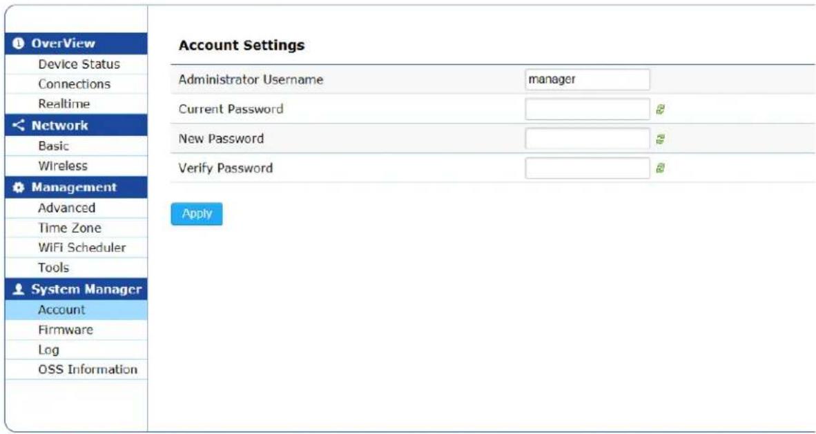
Figure 47. Account Settings Page
Table 43. Account Settings
| Field Description | |
| Administrator Username | Specify the new name. The username can have 1 to 12 alphanumeric characters. The special characters, such as ! % & ( ) * + , - ; <= > ? @ ^ [ | ] ~ are allowed. The name is case-sensitive. The default value is “manager.” |
| Current Password | Specify the current password. The default value is ” friend.” The green two arrows button is a toggle-key, which enables or disables password display. |
| New Password | Specify a new password. The password can have 1 to 12 alphanumeric characters. The special characters, such as ! % & ( ) * + , - ; <= > ? @ ^ [ | ] ~ are allowed. The name is case-sensitive. The green two arrows button is a toggle-key, which enables or disables password display. |
| Verify Password | Specifies the new password again here. The green two arrows button is a toggle-key, which enables or disables password display. |
| Apply Click the | Apply button to activate your changes. |
Firmware Upgrade
You can upgrade the firmware on the device from the Firmware Upgrade section ash shown in Figure 48 on page 72. The fields are defined in Table 44 on page 72.
To upgrade the firmware, do the following procedures:
- Click the Browse button.
- Select the firmware image file.
- Click the Upload button.
The MD5 checksum and file size of the uploaded file are displayed.
- Click the Upgrade button.
The status bar is displayed. After 120 seconds from the completion of the firmware upgrade, the system reboots.
Note
Do not turn off the power during the firmware upgrade.
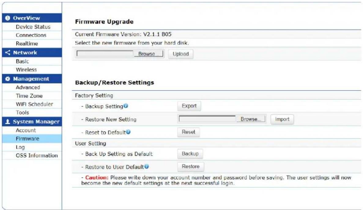
Figure 48. Firmware Upgrade Page
Table 44. Firmware Upgrade
| Field Description | |
| Current Firmware Version | Displays the version number of the firmware that is currently installed on the device. |
| Browse... Click | the Browse... button to specify the firmware file to install. |
| Upload Click the | Upload button to install the specified firmware. |
You can back up a configuration file or restore a configuration from the Backup / Restore Settings section as shown in Figure 48 on page 72.
The fields are defined in Table 45 on page 73.
Table 45. Backup / Restore Settings
| Field Description | ||
| Factory Setting | Backup Setting | Click the Export button to save the current configuration file as backup. The default file name is backup-device_model_name-date.tar.gz. For example, backup-AT-MWS2533AP-2017-07-07.tar.gz. |
| Restore New Setting | Click the Import to install the selected backup configuration file onto the device.NoteDo not turn the power off during the backup configuration restoring. | |
| Reset to Default | Click the Reset button to reset the device to the factory -setting default configuration. | |
| User Setting | Backup Setting as Default | Click the Backup button to save the current configuration file as a user default configuration file. |
| Restore to User Default | Click the Restore button to install the user default configuration file onto the device. | |
Modifying the System Log Settings
To modify the system log settings, select System Manger > Log from the side bar.
System Log You can modify the system log settings from the System Log page as shown in Figure 49. The fields are defined in Table 46.
![Overview Device Status Connections Realtime Network Basic Wireless Management Advanced Time Zone WiFi Scheduler Tools System Manager Account Firmware Log OSS Information System Log Status ● Enable ○ Disable Log type ALL Refresh Clear Jun 10 19:16:01 AT-MWS2533AP cron.info crond[3518]: crond: USER root pld 12298 cmd killall -SIGUSR1 Jun 10 19:15:50 AT-MWS2533AP kern.warn kernel: [89385.788818] Dxd42ccc ) Jun 10 19:15:50 AT-MWS2533AP kern.warn kernel: [89385.775854] FWLOG: [91374136] RATE: ChainMas Jun 10 19:15:35 AT-MWS2533AP kern.warn kernel: [89370.767169] Dx442bfc ) Jun 10 19:15:35 AT-MWS2533AP kern.warn kernel: [89370.754235] FWLOG: [91358921] RATE: ChainMas Jun 10 19:15:09 AT-MWS2533AP kern.warn kernel: [89344.719496] Dxda ) Jun 10 19:15:09 AT-MWS2533AP kern.warn kernel: [89344.717497] Dxd9 ) Jun 10 19:15:09 AT-MWS2533AP kern.warn kernel: [89344.716528] Dxd8 ) Jun 10 19:15:06 AT-MWS2533AP kern.warn kernel: [89343.716060] Dxd7 ) < > Remote Log ○ Enable ● Disable Log Server IP Address 0.0.0.0 Apply Apply saved settings to take effect](/content/2026/06/1189807/images/14fcf8dd0c706e70bc8cd57a906000b69a2f24d7ceb67a7081c1526bd709d707.jpg)
Figure 49. System Log Page
Table 46. System Log
| Field Description | |
| Status Enable or disable system logging. The default setting is enable. | |
| Log Type Select a message severity level to log from the following:☐ ALL☐ Debug☐ Information☐ Notice☐ Warning☐ Error (the AT-MWS2533AP model only)☐ Critical☐ Alert (the AT-MWS2533AP model only)☐ Emergency (the AT-MWS2533AP model only) | |
| Refresh Click the Refresh button to refresh the log display. | |
| Clear Click the Clear button to delete all the log messages. | |
| Remote Log | Enable or disable remote logging. The default setting is disable. |
| Log Server IP Address | Specify the IP address of the host where the log messages are sent. |
| Apply Click the Apply button to save the changes. | |
Displaying OSS Information
To view OSS information, select System Manager > OSS Information from the side bar.
- Management Software User's Guide
- Contents
- Preface 3
- Chapter 1: Getting Started ....7
- Chapter 2: Overview Section ......15
- Chapter 3: Network Section ......29
- Chapter 4: Management Section .... 53
- Chapter 5: System Manager ...... 69
- Safety Symbols Used in this Document
- Note
- Caution
- Warning
- Contacting Allied Telesis
- Chapter 1
- Getting Started
- Starting the Initial Management Session
- Starting a Management Session on the Access Point
- Saving and Applying Your Changes
- Applying Your Changes and Saving Them Permanently
- Figure 2. Applying Your Change
- Saving Your Changes into a Temporary File
- Management VLAN Settings
- Figure 3. Saving Your Change
- Making Your Changes in the Temporary File Take Effect
- Chapter 2
- Overview Section
- Displaying the Device Status
- Memory Information
- LAN Information - IPv4
- LAN Information - IPv6
- Spanning Tree Protocols (STP) Information
- Link Aggregation Control Protocol (LACP) Information
- Wireless LAN Information - 2.4GHz
- Wireless LAN Information - 5GHz
- Statistics
- Displaying Lists of Connected Clients
- Displaying CPU Loading, Traffic, and the Number of Packets
- CPU Loading
- Realtime Connections
- Chapter 3
- Network Section
- Modifying the Basic Settings
- IPv6 Settings
- Spanning Tree Protocol (STP) Settings
- Ling Aggregation Control Protocol (LACP) Settings
- Specifying and Modifying Wireless Settings
- Wireless Security for 2.4GHz and 5GHz
- WEP
- WPA-PSK, WPA2-PSK, and WPA-PSK Mixed
- WPA-Enterprise, WPA2-Enterprise, and WPA Mixed-Enterprise
- Fast Roaming
- Wireless MAC Filter for 2.4GHz and 5GHz
- Wireless Traffic Shaping for 2.4GHz and 5GHz
- Guest Network Settings
- Wireless Security for The Guest Network
- RSSI Threshold (Fast Handover)
- Chapter 4
- Management Section
- Specifying Management Settings
- Sections Not Supported
- Controller Settings
- SNMP Settings
- HTTPS Settings
- Specifying Date, Time, and Time Zone Settings
- Date and Time Settings
- Specifying Auto Reboot Setting and Wi-Fi Scheduler
- Auto Reboot Settings
- Wi-Fi Scheduler
- Using the Management Tools
- Ping Test Parameters
- Traceroute Test Parameters
- Nslookup Test Parameters
- Speed Test Parameters
- Device Discovery
- Chapter 5
- System Manager
- Modifying the Manager Account
- Account Settings
- Firmware Upgrade
- Modifying the System Log Settings
- Displaying OSS Information
Brand : Allied Telesis
Model : AT-MWS2533AP
Category : Access Point