ITC8113 - Tablet ADS-TEC - Free user manual and instructions
Find the device manual for free ITC8113 ADS-TEC in PDF.


User questions about ITC8113 ADS-TEC
0 question about this device. Answer the ones you know or ask your own.
Ask a new question about this device
Download the instructions for your Tablet in PDF format for free! Find your manual ITC8113 - ADS-TEC and take your electronic device back in hand. On this page are published all the documents necessary for the use of your device. ITC8113 by ADS-TEC.
USER MANUAL ITC8113 ADS-TEC
text_image
Version 2.1 Translation of the original instruction manual TabX indu computer adslogInstruction manual
Tablet PCs
ITC8113 / TabX®
Table of Contents
1 Notes....5
1.1 General remark 5
1.2 Limitation of liability 5
1.3 Manufacturer 6
1.4 Relevant device documentation 6
2 Safety instructions ....7
2.1 Structure of safety instructions 7
2.2 Graduation of risk level 7
2.3 Explanation of used symbols 7
2.4 Symbols 8
2.5 Data, figures and modifications 8
2.6 Trademarks 8
2.7 Copyright 9
2.8 Environmental conditions 9
2.9 Standards 10
2.10 Scope of delivery 11
2.11 Features of the ITC8113 12
2.12 External dimensions ITC8113 14
3 Operating and safety instructions....15
3.1 Operating location 16
3.2 Damage due to improper use 16
3.3 Warranty / repairs 16
3.4 Intended use 16
3.5 Improper use 17
3.6 Treatment and disposal of lithium batteries 17
3.7 Electrostatically sensitive components 18
3.8 Cleaning the device 18
4 Commissioning....19
4.1 Procedure 19
5 Operation 20
5.1 Full HD display 20
5.2 10-finger multifunction touch-screen 21
5.3 Front status LEDs 22
5.4 Front panel operation keys 24
5.5 Landscape/portrait function 27
6 Interfaces....28
6.1 Interfaces on the side 28
6.1.1 Standard version 28
6.1.2 Versions with DisplayPort 29
6.2 Power supply via the power adapter 30
6.3 Power supply via stick-type batteries 31
6.4 USB interfaces 33
6.5 Network connection (RJ45) 34
6.6 Microphone 35
6.7 Speakers 36
7 Wireless....37
7.1 WLAN 37
7.2 Bluetooth 38
7.3 UMTS / LTE (optional) 38
8 Drives 39
8.1 Hard disk / Flash SSD 39
8.2 External drives 39
9 Software....40
9.1 Reinstalling the operating system 40
9.2 Configuration Center 40
10 Technical details....41
10.1 Technical details of the ITC8113 41
10.2 Technical details of the stick-type batteries 42
11 Accessories 43
11.1 Transport case 43
11.2 Battery charging station 44
11.3 Replacement power adapter 49
11.4 Vehicle power adapter 49
11.5 Replacement stick-type battery 50
11.6 Rotatable and tiltable wall table adapter 51
11.7 Tip-up feet 55
11.8 3-point strap 56
11.9 Hand strap 61
11.10 Protection cover 63
12 Component replacement....64
12.1 Opening the service slot 64
12.2 Changing the mass storage device 66
12.3 Replacing the BIOS battery 67
13 Service & support....68
13.1 ADS-TEC support 68
13.2 Company address 68
1 Notes
1.1 General remark
This instruction manual is intended to ensure safe and efficient handling and operation of IT Infrastructure products.
The instruction manuals must be read carefully by personnel before commencing any type of work.
All of the safety notices and handling instructions given in the manual must be obeyed in order to ensure that work is carried out safely.
Operation of the system is subject to the laws and regulations which are applicable in the respective country at national, federal, European and international level.
The generally accepted rules of technology, usually in the form of standards, directives, regulations, conditions and technical rules specified by national and federal organisations as well as trade associations and committees for the field of specialisation concerned, shall apply.
Figures used in this instruction manual are provided for basic understanding and may differ from the actual design.
The operator/operating company is independently responsible for compliance with and observance of any subsequently introduced technical innovations or new legal requirements, as well as for all usual obligations of the operator/operating company.
The original version of this instruction manual was written in German. All non-German versions of this instruction manual are translations of the German instruction manual.
1.2 Limitation of liability
ads-tec Industrial IT GmbH shall not be liable for personal injury, property damage or damage caused to the device as well as consequential damage that is/was the result of non-compliance with this instruction manual, improper use of the device, repairs and other actions on the device by unqualified electricians and electricians not certified by ADS-TEC, or that is/was the result of using unapproved replacement parts. Failure to observe the maintenance intervals shall also result in exclusion from liability.
Furthermore, it is strictly forbidden to make any unauthorised alterations or technical modifications to the device.
1.3 Manufacturer
The manufacturer of the product is ads-tec Industrial IT GmbH. The company is referred to in the following as ADS-TEC.
1.4 Relevant device documentation
The following documents are decisive to device setup and operation:
Instruction manual:
Contains information for installation, commissioning and operation of the device along with technical data of the device hardware.
Website
You can download drivers, software, user manuals, leaflets and flyers from the Download section of our website www.ads-tec.de.
2 Safety instructions
2.1 Structure of safety instructions
The signal word classifies the hazard.
Reference to the type/consequences and source of the hazard is made underneath the signal word.
Instructions for preventing the hazard are identified by an arrow (→).

! SIGNAL WORD
Type/consequences of hazard!
- Source of hazard
→ Measures to prevent hazard
2.2 Graduation of risk level
The signal word classifies the hazard.
Instructions for preventing the hazard are identified by an arrow (→).
2.3 Explanation of used symbols

DANGER
Indicates an imminent danger. If not avoided, death or severe injury will result.

WARNING
Indicates a possible danger. If not avoided, death or severe injury could result.

CAUTION
Indicates a possible danger. If not avoided, light or minor injuries could result.
ATTENTION
Indicates a possibly damaging situation. If not avoided, the system or something in its surroundings could be damaged.

Recommendation for use:
The symbol "Recommendation for use" indicates terms and/or conditions that strictly need to be observed to ensure optimised and/or zero-defect operation. Tips and suggestions for the efficient use of the device and software optimisation are also provided.
2.4 Symbols
| Symbol | Meaning |
 | Designation of batteries in accordance with § 13 of the German Battery Act (BattG). Batteries may not be disposed of with household waste, but must rather be disposed of separately. Used batteries must be returned to the point of sale or a disposal system. |
 | Labelling of electrical and electronic devices in accordance with § 7 of the German Electrical and Electronic Equipment Act (ElektroG). Electrical and electronic devices must not be disposed of with household waste, but must rather be taken to a collection point for waste electrical equipment. Such a collection point is generally operated by public waste management authorities, i.e., by municipalities. |
 | Symbol for the protective earth connection |
2.5 Data, figures and modifications
All data, text and figures were prepared to the best of our knowledge. They do not represent any assurance for the properties themselves. Despite taking utmost care, no liability can be assumed for accuracy, completeness and actuality of the information. Subject to changes.
2.6 Trademarks
It is noted that any software and/or hardware trademarks and any company brand names mentioned in this documentation are all subject to the general trademark protection rights.
StoraXe®, TabX® and Big-LinX® are registered trademarks of ADS-TEC.
All other third-party trademarks used are hereby acknowledged.
In the case of infringement of trademark rights, ADS-TEC reserves the right to exercise all rights.
2.7 Copyright
This instruction manual is protected by copyright. For the authorised user, simple usage rights are granted within the scope of the intent of the contract. Any modified use or exploitation of the provided content, particularly duplication, modification or publishing in whatever form is permitted only with the prior consent of ADS-TEC.
In the case of copyright infringement, ADS-TEC reserves the right to exercise all rights.
2.8 Environmental conditions
The device can be put into operation and used under the following conditions. Failure to observe any one of these conditions will invalidate the warranty. ADS-TEC cannot be held liable for any damages arising from improper use and handling.
• Temperature for ITC8113
in operation 0 ... +40°C
for storage -20 to +60°C
- Humidity
in operation 10 ... 85% without condensate
for storage 10 ... 85% without condensate
- Vibration
in operation environmental class 7M3
2G, 2 - 500 Hz
(DIN EN 60721-3-7)
- Shock resistance
in operation environmental class 7M3
30 G, with a sinusoidal half-wave of 11 ms
(DIN EN 60721-3-7)
2.9 Standards
The manufacturer hereby declares that this device has been marked with the CE mark in accordance with the basic requirements and other relevant conditions of the following European Directives:
• 2011/65/EU, RoHs Directive
• 2014/30/EU, EMC Directive
• 2014/53/EU, RED Directive
• 2014/35/EU, Low Voltage Directive

The EU conformity declaration can be requested at http://www.ads-tec.de/support/support-anfrage.html and is available for download at http://www.ads-tec.de/support/download/eg-konformitaetserklaerung.html.

The device variants with DisplayPort are certified according to UL 60950-1.
Electromagnetic compatibility (EMC): The product is a class B device.

Recommendation for use:
For full compliance with the EMC legislation, all components and cables used for device connection must also be compliant with these requirements. It is therefore necessary to employ BUS and LAN cables with shielded connectors and these must be installed as per the instructions contained in the instruction manual.
2.10 Scope of delivery
Check the contents of the package for completeness and for any damages:
Should the device have evident signs of damages caused, e.g., by improper operation or storage conditions or due to improper use or handling, the device and accessories must be shut down immediately. Ensure that they are secured against being started up accidentally.
- 1 x device
• 1 x power adapter 20VDC - 2 x stick-type battery
- Quick Start Guide
Optional scope of delivery:
- ITC8113 accessories acc. to delivery note
2.11 Features of the ITC8113
The industrial tablet computer from ADS-TEC has been consistently further developed for professional and mobile use.
High performance, brilliant Full HD display and optimised for applications in service environments –
the new TabX - ITC8113 scores high marks both for indoor and outdoor use.
Front side
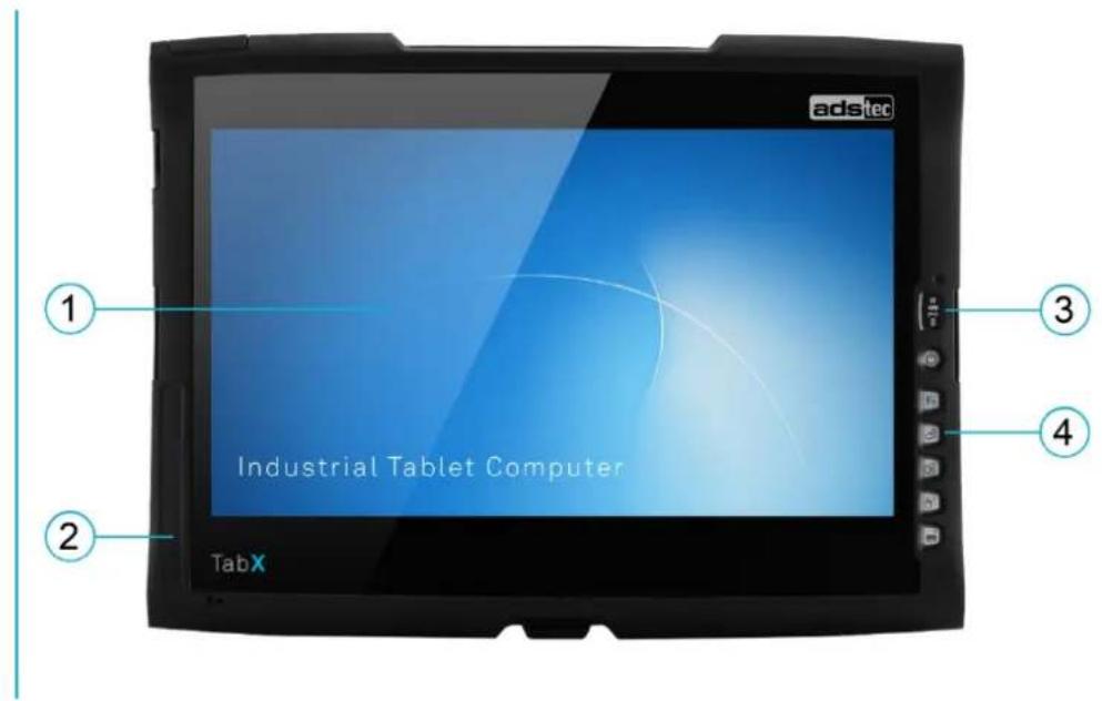
text_image
adstec Industrial Tablet Computer TabXNo. Description
| 1 | HD display with 10-finger touch-screen(1920 x 1080 pixels) |
| 2 | Monocoque frame |
| 3 | Status LEDs |
| 4 | Front keys with lighting |
Rear side
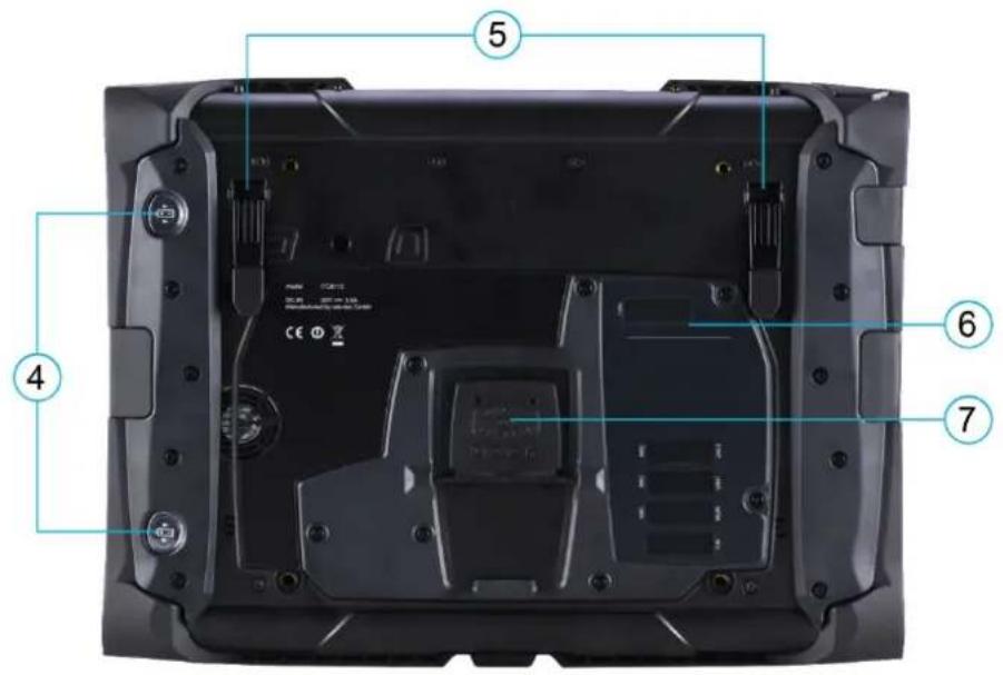
text_image
Labeled diagram of a laptop rear panel showing internal components and numbered partsNo. Description
4 Battery ejector
5 Set-up mechanism
6 Service slot
7 Docking connector
2.12 External dimensions ITC8113
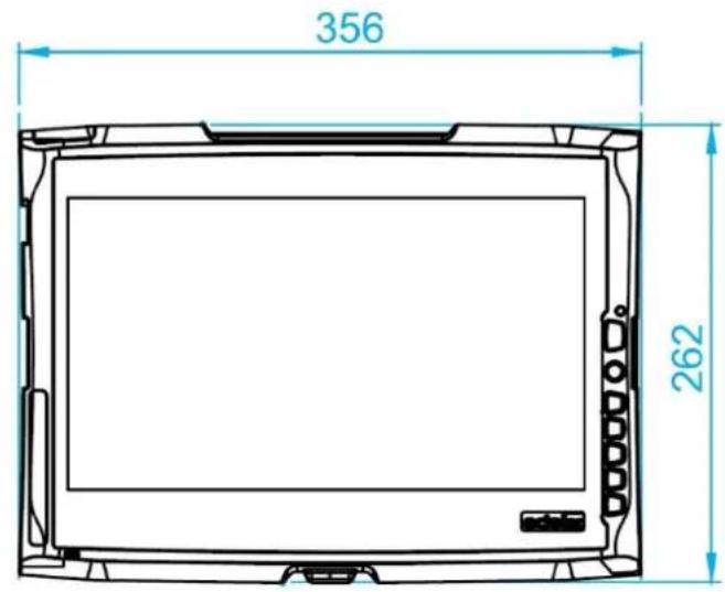
text_image
356 262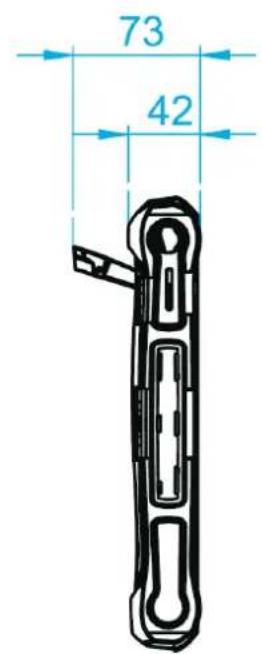
text_image
73 42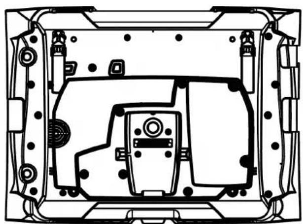
natural_image
Technical line drawing of a mechanical component with internal structural layout (no text or symbols)3 Operating and safety instructions
The device operates under electrical voltage and contains highly sensitive components. Intervention by the user is required only for connecting the power supply lines. Should any further modifications be required, it is necessary to consult either with the manufacturer directly or with service personnel authorised by the manufacturer. The device must be de-energised during work. Appropriate measures must be taken to prevent electrostatic discharges on components. If the device is opened up by an unauthorised person, the user may be subject to hazards and the warranty is invalidated.
General information
• All users must read this manual and have access to it at all times.
- Installation, commissioning and operation may only be performed by qualified and trained personnel.
- The safety notices and the manual itself must be observed by all persons who work with this device.
- At the installation site the valid guidelines and regulations for accident prevention must be observed.
- The manual contains the most important instructions on how to use this device in a safe way.
- Appropriate storage, proper transport, installation and commissioning, as well as careful operation are prerequisites for ensuring safe and proper operation of the device.
- The device can be cleaned by using a soft cloth and a commercially available glass cleaning agent (e.g. Sidolin) with low alcohol content.
ATTENTION
To prevent damage to the device, all cable lines (power supply, interface cables) must only be connected while the device is switched off.
3.1 Operating location
The device is optimised for use with applications in a service environment.
Make certain that the specified environmental conditions are maintained at all times. Use in non-specified environments, i.e., on board ships, in explosive atmospheres or at extreme elevations, is prohibited.
ATTENTION
The device may only be switched on after acclimatising to the ambient temperature in order to avoid condensate accumulation. This also applies if the device is exposed to extreme temperature fluctuations.
To avoid overheating in operation:
The device must not be exposed to direct radiation by sunlight or any other light source.
3.2 Damage due to improper use
Should the device have evident signs of damages caused, e.g., by improper operation or storage conditions or due to improper use or handling, the device must be shut down immediately. Ensure that it is secured against being started up accidentally.
3.3 Warranty / repairs
During the device warranty period, any repairs must only be performed by the manufacturer or by service personnel that has been authorised by the manufacturer.
3.4 Intended use
The device is used for diagnostics, visualisation and control of a wide range of processes in a service environment, among other places. The device is designed for indoor and outdoor applications.
The device is only to be assembled, installed and operated within the permissible specifications.
3.5 Improper use
Operation other than or beyond that described for the device shall be deemed improper use.
The device is not allowed to be used to control vehicles or for applications for which further approvals beyond the manufacturer's declaration are necessary, e.g. applications with explosion hazard, medical technology, shipping industry.
The device must not be put into operation in the case of transport damage or nonconformity with the specifications and, if necessary, must be taken out of operation in the case of changing conditions.
In the case of improper use, ADS-TEC shall not accept responsibility or liability for injury or damage that is directly or indirectly attributable to the handling of the device.
3.6 Treatment and disposal of lithium batteries
- This device contains a BIOS battery. The battery has a life cycle of 3 - 5 years depending on which load is applied.
- This device contains up to two rechargeable stick-type batteries for supplying the device in mobile use.


WARNING
Danger of explosion, fire and chemical burns!
- Danger of explosion if using incorrect battery types. Batteries may only be replaced by the same type, or by a type recommended by the manufacturer (see chapter Technical Data).
- Batteries should not be exposed to fire, soldered, opened, short-circuited, reversed or heated above 100 °C and they should be protected against sunlight, moisture and condensation.
- Only charge rechargeable batteries. Never try to recharge batteries that have not been designed for this purpose!
ATTENTION
The more the battery is exposed to higher temperatures, the faster it ages.
Defective batteries are to be disposed of in accordance with the valid legal regulations.
3.7 Electrostatically sensitive components
ATTENTION
Damage due to electrostatic discharges
All installation and service work performed on the device must be performed only under safe, secure and de-energised conditions.
Always adhere to the safety measures applicable when handling components at risk of being damaged by electrostatic discharges.
The provisions of DIN EN 61340-5-1 / DIN EN 61340-5-2 apply.
3.8 Cleaning the device
For cleaning we recommend applying a cleaning agent for household use.
Additionally, we have tested the following disinfectant: Meliseptol® produced by
B. Braun Melsungen AG. It can be used following the recommendations for use and dosage indicated by the manufacturer.
4 Commissioning
The power supply connection and the interfaces on the device are located on the side of the housing. All supply leads and all required data leads have to be connected before commissioning.
ATTENTION
The device must be switched off before connecting or disconnecting any cables in order to prevent damage to the electronics!
The device may only be switched on after acclimatising to the ambient temperature in order to avoid condensate accumulation. Make sure to meet the permissible voltage for this device.
After switching off and before switching on you must wait for at least 5 seconds.

Recommendation for use:
The shielding of a data cable must always be connected with the connector housing (EMC).
For embedded operating systems, the interfaces must be explicitly enabled and the necessary drivers installed in order to use them.

Recommendation for use:
When using accessories, proceed according to chapter Accessories.
4.1 Procedure
No. Description
| Check for operational readiness | |
| 1 | Check the battery charge state(see chapter Battery operation) |
| 2 | Insert battery into the device and snap into place(see chapter Battery operation) |
| 3 | Connect power adapter (if necessary) |
| 4 | Start the device (ON/OFF pushbutton) and activate in the operating system by entering the licence information |
5 Operation
5.1 Full HD display
The device is equipped with a full-HD display with multifunction touch-screen.
The non-reflective display offers a maximum resolution of 1920 x 1080 pixels.

text_image
adsitec Industrial Tablet Computer TabX Full HD5.2 10-finger multifunction touch-screen
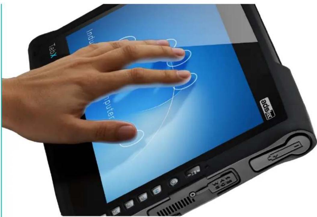
The device is equipped with a multifunction touch-screen that supports multifinger operation. The driver software necessary for use is already integrated in the respective operating system.

Recommendation for use:
The touch calibration data is stored independent of the operating system and requires no additional calibration by the user.
text_image
Induy Computer TabY WAN SCAN
Recommendation for use:
With older operating systems, a driver is required for the touch-screen functionality. The appropriate driver can be downloaded from http://www.ads-tec.de/industrial-it/download/ for the respective device series.
5.3 Front status LEDs

text_image
ads Industrial Tablet Computer TabX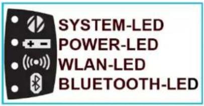
text_image
SYSTEM-LED POWER-LED WLAN-LED BLUETOOTH-LEDThe device is equipped with various status LEDs on the front.
These LEDs indicate current events such as system activity, battery state, and WLAN and Bluetooth activity.
| System LED | Behaviour | Description | |
 | - | Device is not connected to any voltage source (power supply/battery) | |
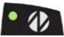 | Static | Device is connected to a power source (power supply/battery) and switched on. | |
 |  | Flashing | The device is in suspend mode (mode can be set via the operating system, reactivation via the power button) |
 | Static | Device accesses the mass storage device | |
| Power LED | |||
| - | Device is not connected to a voltage source | ||
| Static | Device is supplied with charged battery | ||
| Static | Device is supplied with external voltage | ||
| Flashing | Stick-style batteries are being charged (The device must be connected to a voltage source (power adapter)) | ||
| Power LED | |||
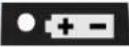 | - | Device is not connected to a voltage source | |
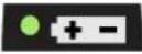 | Static | Device is supplied with charged battery | |
 | Static | Device is supplied with external voltage | |
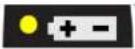 |  | Flashing | Stick-style batteries are being charged(The device must be connected to a voltage source (power adapter)) |
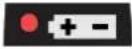 | Static | Device is operating with the remaining capacity of the battery(ies) |
WLAN LED
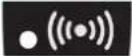 | Static | WLAN module is not switched on | |
 | Static | WLAN module is switched on | |
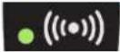 | 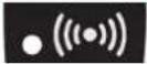 | Flashing | Device is connected to a WLAN network and has data traffic |
| Bluetooth LED | |||
 | Static | Bluetooth module is deactivated. | |
 | Static | Bluetooth module is activated. | |
 |  | Flashing | Device is connected to a Bluetooth subscriber and has data traffic |
Bluetooth LED
5.4 Front panel operation keys
text_image
adstec Industrial Tablet Computer TabX
Recommendation for use:
After activating the operating system, the soft keyboard can be opened using the corresponding front key.
If the soft keyboard is not installed, it can be added.
Details can be found in the instruction manual for the Configuration Center.
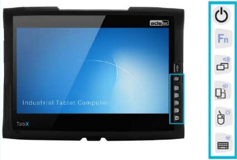
The keys on the front are assigned the following functions by a special driver in the soft keyboard:
 | Hold down the ON/OFF pushbutton for 0.5 sec. |
 | Shift key (SHIFT) for activating the second keyboard level. This key must be pressed simultaneously with the desired function key. |
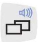 | Level 1:Change task (Alt+ESC) in WindowsLevel 2:Increase system volume |
 | Level 1:Switch from landscape display view to portrait display viewLevel 2:Decrease system volume |
 | Level 1:Right mouse-key functionLevel 2:Increase display brightness |
 | Level 1:Activate and deactivate the soft keyboard for letter/character input by using the touch screenLevel 2:Decrease display brightness |

Recommendation for use:
With the exception of the ON/OFF pushbutton and the Fn key, each of the function keys on the front has two function levels.
The primary function can be executed by simply pressing the respective key.
The second function level of each key (small icon in the upper right) can be executed by first pressing the Fn key followed by the desired function key.
It is important that the Fn key always be kept held down to activate the second function level.

Recommendation for use:
If the soft keyboard is not installed, level 1 of the ABC key has no function. Furthermore, no graphical feedback is provided when changing the display brightness.
5.5 Landscape/portrait function
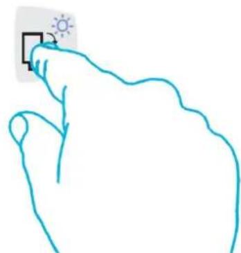
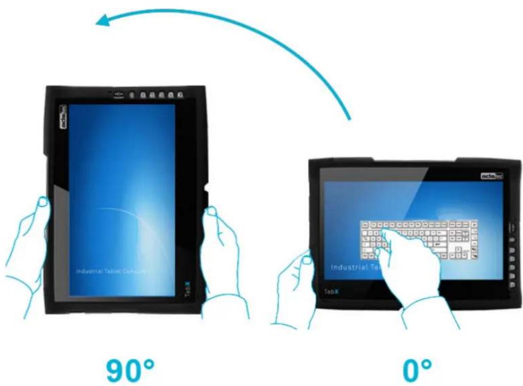
Press the Landscape/portrait key to rotate from 0^ to 90^ . Press the key again to return to the initial state.
natural_image
Simple line drawing of a hand pointing at a square with a sun icon (no text or symbols)The function ensures that the preset calibration for 0^ or 90^ is always loaded.
text_image
90° Industrial Tablet Concepts TabX Industrial Tablet TabX 0°ATTENTION
Keep the air outlet at the right near the card slots free of obstruction.
To protect the device from overheating, make certain that the air outlet slots are not covered or that the air outlet is not impeded.
6 Interfaces
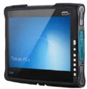
All available interfaces are located on the side of the device. They are protected by a rubber cover.
ATTENTION
Breaching of IP protection
IP protection is no longer provided if the rubber covers are open.
→ Only open the rubber covers when using the interfaces.

Recommendation for use:
Only use the accessories and replacement parts released by ADS-TEC.
6.1 Interfaces on the side
6.1.1 Standard version
text_image
Tablet PCs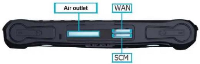
text_image
Air outlet WAN SCM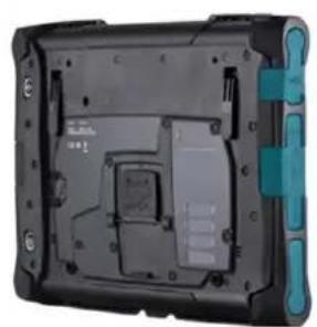
natural_image
Back view of a black electronic device with internal components and mounting holes (no visible text or symbols)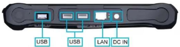
text_image
USB USB LAN DC IN6.1.2 Versions with DisplayPort
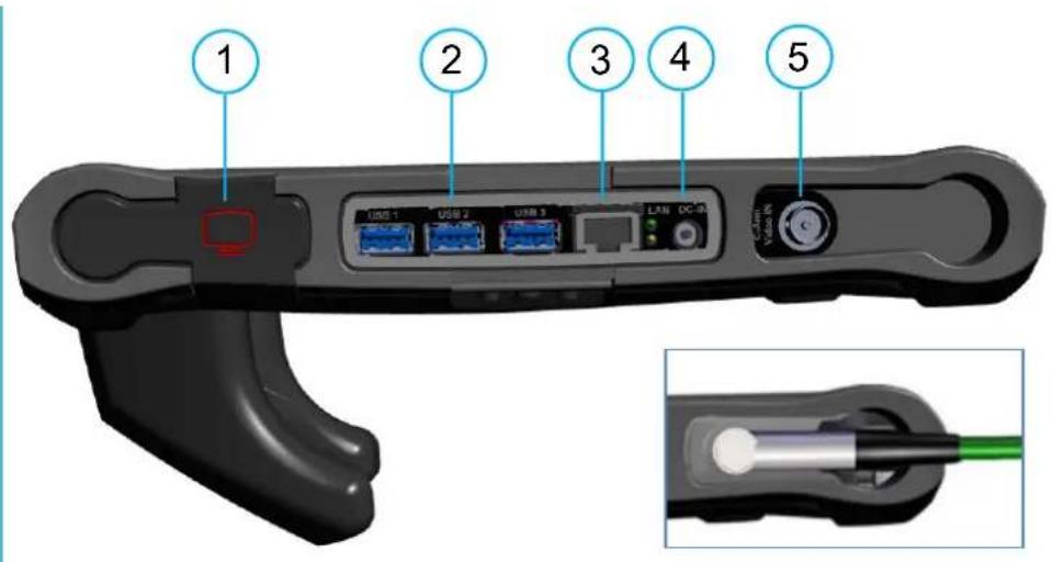
text_image
1 2 3 4 5 USB 1 USB 2 USB 3 LAN DC-IR Video INNo. Description
1 DisplayPort (Video OUT)
2 USB interfaces
3 LAN interface
4 Power supply
5 Depending on the version of the device:
- BNC connector (analogue video IN) - or -
- LAN via ODU connector - or -
- None
6.2 Power supply via the power adapter
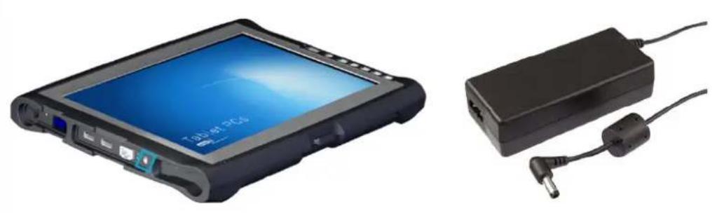
Technical data of the power adapter
• Power consumption: 70 watts
- Input voltage: 100...240 VAC
• Output voltage: 20 VDC
• Grid frequency: 47...63 Hz
• Current consumption: 3.5A (230 VAC)
6.3 Power supply via stick-type batteries
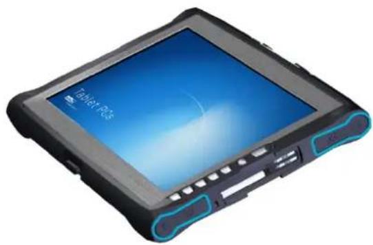
The device is equipped with two battery slots that can be used as an alternative for supplying the device with power. In addition, the device is equipped with the hot-swap function, which allows batteries to be changed without restarting.
natural_image
Black and blue electronic device with a display screen showing 'Tablet Plus' and control buttons (no readable text beyond branding)The batteries are automatically charged during mains operation (20 VDC).

Recommendation for use:
If both batteries are to be changed while in operation, power is to be supplied via the included power adapter.
If changing just one battery, it can be changed without an external power supply.
Querying the battery state / changing the battery
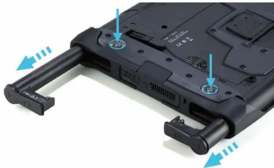
The device batteries can be removed using a mechanical ejector located on the rear side of the device. To do this, press the respective key.
natural_image
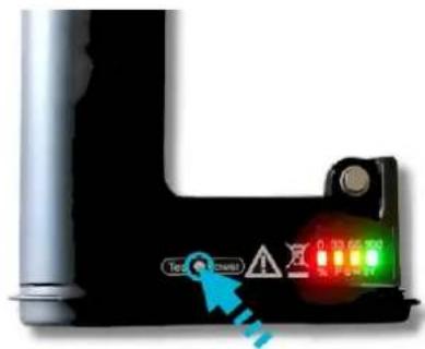
Close-up of a black laptop with attached hardware and two blue arrows indicating fasteners or sensors (no text or symbols visible)The charge state can be queried via the "Test Power" button on the battery. The charge state indicator illuminates for a few seconds and displays the current charge state on a scale from 0 to 100.
text_image
Test Covered 0.23 65 70 0.23 65 70LED
State of charge
| Red LED blinks | 0 ... 10% |
| Red LED on | 11 ... 32% |
| Red and orange LEDs on | 33 ... 65% |
| Red, yellow and orange LEDs on | 66 ... 94% |
| All the LEDs on | 95 ... 100% |

Recommendation for use:
If the device is in operation, the battery state can be queried via the operating system.
6.4 USB interfaces
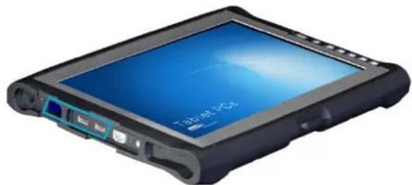
The USB interfaces are used for connecting peripherals with USB connection. These interfaces comply with the USB 3.0 standard requirements.
natural_image
Exterior view of a black rectangular electronic device with a blue screen displaying 'Tab at 20°C' (no other text or symbols visible)USB 3.0
| Pin | Signal |
| 1 | VBUS |
| 2 | D - |
| 3 | D + |
| 4 | GND |
| 5 | StdA_SSRX- |
| 6 | StdA_SSRX+ |
| 7 | GND_DRAIN |
| 8 | StdA_SSTX- |
| 9 | StdA_SSTX+ |
natural_image
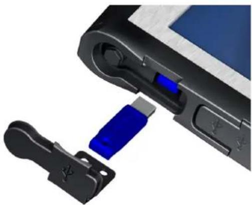
Close-up of a device's internal components, showing a blue USB plug inserted into a black plastic clip (no text or symbols visible)
Recommendation for use:
The recessed USB interface (not available in the Display port version) enables the use of a USB dongle. This can be operated in the device.
The two side USB interfaces are designed for 1A.
Exception: the recessed USB interface, which is designed for 1.8A.
6.5 Network connection (RJ45)
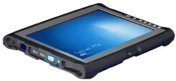
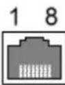
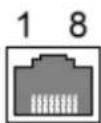
If the drivers required for functioning are installed on the device, the device may be integrated in an Ethernet network supporting the 10/100/1000Mbit standard by using the Ethernet 10/100/1000 BaseT network connector.
The specifications of this network topology must be observed. If the drivers necessary for the function are not installed, they can be downloaded from the website www.ads-tec.de.
natural_image
3D rendering of a black rectangular electronic device with a blue screen and ports (no visible text or symbols)10/100Mbit
| Pin | Signal |
| 1 TX + | |
| 2 TX - | |
| 3 RX + | |
| 4 NC | |
| 5 NC | |
| 6 RX - | |
| 7 NC | |
| 8 NC |
1000 BaseT
| Pin | Signal |
| 1 D1+ | |
| 2 D1- | |
| 3 D2+ | |
| 4 D3+ | |
| 5 D3- | |
| 6 D2- | |
| 7 D4+ | |
| 8 D4- |
6.6 Microphone
The device is also equipped with an internal microphone on the front side. The microphone can be configured via the integrated volume control in the operating system.

text_image
adstec Industrial Tablet Computer TabX6.7 Speakers
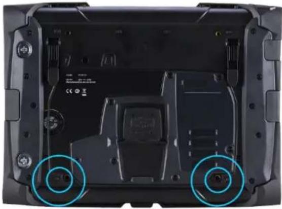
The device is equipped with two internal speakers.
natural_image
Back view of a black electronic device showing internal components and two blue circular annotations highlighting areas of interest (no readable text or symbols)
natural_image
Blue speaker icon with sound waves, no text or symbols presentSpeaker positions
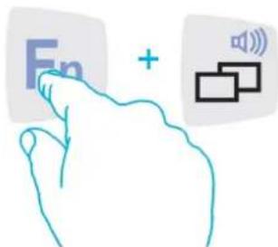
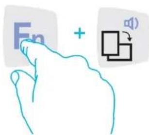
The volume can be set up by using the device front keys.
When activating the described key combinations, the volume level is modified accordingly. If the soft keyboard has been installed, the system volume is additionally displayed by a bar graph.
text_image
Fn +Button combination - increase volume
text_image
Fn +Button combination - reduce volume
7 Wireless
The device features various wireless options for establishing a connection to networks or compatible terminals.

Recommendation for use:
The appropriate drivers can be downloaded from the website http://www.ads-tec.de for the respective device series.
7.1 WLAN
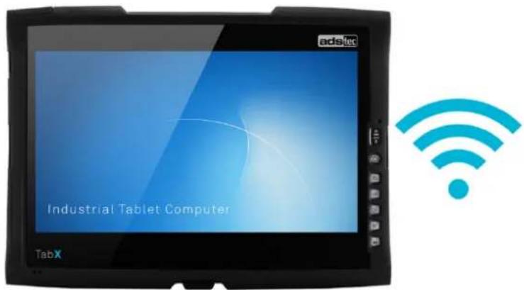
The device is equipped with a wireless LAN card and can be integrated wirelessly in any IT infrastructure.

Recommendation for use:
The wireless card supports the following standards:
Wireless LAN 802.11 a / g / n
text_image
adstec Industrial Tablet Computer TabX7.2 Bluetooth
The device is equipped with a Bluetooth module.

Recommendation for use:
The wireless module supports the Bluetooth 4.0 standard.
The built-in wireless module meets the CLASS 1 / CLASS 2 standard.

text_image
Industrial Tablet Computer TabX7.3 UMTS / LTE (optional)
The device is equipped with a mobile communications module and is able to communicate with the Internet even without a wireless infrastructure.

Recommendation for use:
An activated SIM card is required for use.
There are costs/fees associated with mobile data use.
Further information is available from your mobile provider.
The SIM card is to be inserted while the device is in the off state.
The mobile communications module supports the following standards: UMTS (3G) / LTE (4G)

text_image
Industrial Tablet Computer TabX8 Drives
8.1 Hard disk / Flash SSD
The storage medium is selected according to the customer requirements. The following options are available for storage:
– Solid-state drive (SSD)
– An HDD is optionally available.
— The capacity is dependent on the desired operating system and the used programs.
8.2 External drives
External storage media can be connected via USB interfaces.
Note here the connecting lines in chapter Interfaces.
ATTENTION
Connecting or disconnecting external drives in operation is not admissible, since it cannot be excluded that the drive might be in use while connecting or disconnecting it.
Data loss might result in the event of non-compliance!
9 Software
9.1 Reinstalling the operating system
The device will be delivered with a pre-installed operating system depending on what the customer wants. The drivers required for this, are already installed and the operating system will be enabled by entering the licence information.

Recommendation for use:
The device does not have an integrated CD drive. If the hard disk has been reformatted, the operating system can be reinstalled via the existing interfaces.
Installation of the operating system via a USB interface
- Connect an external USB drive and a keyboard.
- Restart the device and press the ESC key to enter the boot menu.
- Insert an operating system CD into the external drive.
- Select booting from the external drive in the boot menu and start.
- Install the operating system and set the basic data.
- For touch screen devices, the touch screen driver and soft keyboard should be installed for full function.
Installation of the operating system via PXE
Alternatively, the operating system can also be installed over the network using the PXE functionality (PXE = Preboot Execution Environment). To do this, the corresponding BootROM extension must first be activated in the BIOS and then selected in the boot menu.
The further procedure depends on the network environment and the operating system to be installed.
9.2 Configuration Center
If there is a preinstalled operating system on your device ex works, ADS-TEC provides software modules. These software modules are specially matched to the respective device and can be called up in the Configuration Center.
10 Technical details
10.1 Technical details of the ITC8113
ITC8113
| Housing | Glass-fibre reinforced monocoque frame | |
| Display | Resolution | 13.3" TFT, Full HD, LED backlight1920 x 1080 pixels |
| Touch | PCAP multifunction industrial touch screen (10-finger) | |
| Processor | Intel® | Intel® CeleronTM 1.6 GHz (2980U)Intel® CoreTM i5 1.9 GHz (4300U) |
| RAM | 4 GB DDR3 RAM (optional 8 GB DDR3 RAM) | |
| Mass storage | Hard drive 2.5" SATA, SSD (min. 100 GB) | |
| Network | 1 x Ethernet (10/100/1000 Mbit/s) RJ 45 | |
| Interfaces | 2 x USB 3.0 (each port has a load capacity of max. 1 A)Optional: 1 x USB 3.0, recessed installation (max. 1.8 A)Docking connectorOptional: Display-Port | |
| Power adapter | External power adapter (input 100-240 VAC; output 20 VDC) | |
| BIOS battery | Lithium battery CR2032 230mAhArticle no. ADS-TEC: DZ-SONS-04075-1 | |
| Operating system | Windows® Embedded Standard 7 (64 bit)Windows® Embedded 8.1 Industry Pro (64 bit)Windows® 10 IoT | |
| Protection class | IP 53 / front IP 65 (tested by ADS-TEC, not evaluated by UL) | |
| Operating temperature | 0 to +40°C | |
| Dimensions (W x H x D) | 356 x 262 x 42 mm (73 mm with tip-up feet in the folded out position) | |
| Weight | Approx. 1.8 kg without batteries | |
| Vibration | DIN EN 60068-2-6 | |
| Shock resistance | DIN EN 60068-2-27 | |
| Humidity | 10 to 85% non-condensing | |
10.2 Technical details of the stick-type batteries
Stick-type battery type DZ-PCKO-06097-8/x
| Nominal voltage | 14.6 V |
| Minimum capacity | 2750 mAh |
| Nominal energy | 40 Wh |
| Cell | Samsung INR18650-29E |
| Number of cells | 4 |
| ADS-TEC article no. | DZ-PCKO-06097-8/x |
| Admissible operating temperature range (temperature of the cells) | Charging: +2...+43 °CDischarging: -17...+58 °C |
| Charging procedure | Charging voltage: 16.4 VCharging current: max. 1.4 A |
| Charging time (with charging station or ITC) | One battery inserted: 2,5 hTwo batteries inserted: 4 h |
| Operating time of the ITC with two fully charged batteries | Mobile Mark 2012: 7 h 50 minFull-load operation: 3 h 30 min |
| Full cycles under laboratory conditions | 1 test cycle = CCCV* charging with 0.5 C and 0.05 C cut-off current and discharging with 1 C and 10 V cut-off voltage.The cycles are in a stretch. Afterwards, the following applies: after 500 cycles, 70% of the nominal capacity is still available.*CCCV = Constant Current Constant Voltage |
| Storage: temperature range (cell temperature) for long-term storage | Up to 1 month:-18 °C ... 60 °CUp to 3 months:-18 °C ... 45 °CUp to 9 months:-18 °C ... 25 °CLonger than 9 months:-18 °C ... 25 °C ⇒ recharge on a regular basis! |
| Ageing of the cells | If the temperature range for storage is respected, with an initial state of charge of 50% and after the time has elapsed, at least 80% of the nominal capacity are still available. Lower storage temperatures will slow down the ageing process.Recommendation for long-term storage: For storing the battery in an optimum way, at the beginning of storage, the battery should have a state of charge of 30 ... 70%. |
| Self-discharge of the cells | The following applies for the temperature range -18 ... 25 °C:Storage in a shut-down ITC (Zero Power Mode active) with 2 inserted batteries with each approx. 30% SOC (state of charge): After approx. 40 days, 0% SOC will be reached (version DZ-PCKO-06097-8/F and higher).Storage of the battery removed from the ITC with 30% SOC: At the earliest after 300 days of storage, 0% SOC will be reached. |

Recommendations in the case of prolonged non-use of the device
- If the device is not used for a longer period of time (e.g. for more than a week), remove the stick-type batteries from the ITC. This reduces the discharge of the batteries to the technically possible minimum.
- Regularly check the charge state (e.g. every 3 months). The battery must be charged at the latest if the red LED of the charge state display blinks.
The internal self-discharge of the battery continues due to the laws of chemistry, even if the nominal charge state is already at 0%. This results in a damaging deep discharge after a prolonged period of time (version DZ-PCKO-06097-8/F: typically after 90 days). Due to safety reasons the battery's integrated electronics prevent the reuse of such batteries.
11 Accessories
11.1 Transport case
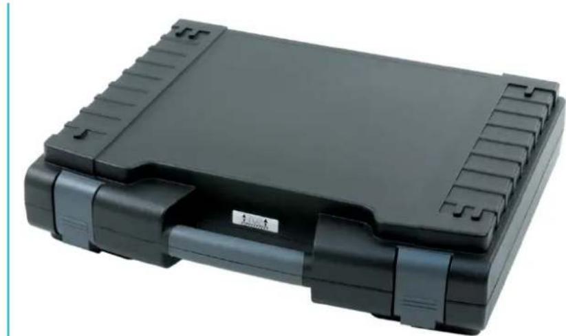
The optionally available transport case allows the device to be transported safely. In addition, the transport case offers the possibility to store accessory parts such as batteries, power adapters and software.
natural_image
Black rectangular electronic device with multiple ports and a label on the side (no readable text or symbols)Exterior view of sample case
Please note: The transport case is not a UL-certified accessory.
11.2 Battery charging station
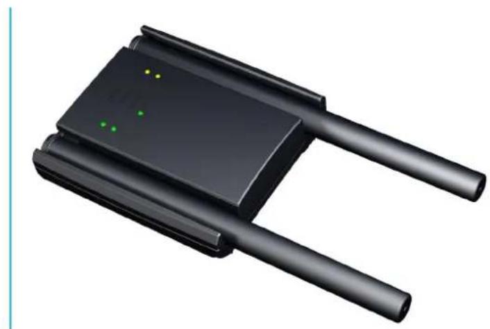
A battery charging station is optionally available for charging the device batteries (Article no.: DV-ITCOPT-002 001-AA).
The battery charging station has two battery slots. Two batteries can thereby be charged simultaneously.
natural_image
3D rendering of a black electronic component with two leads and three green dots on top (no text or symbols)Please note: The battery charging station is not a UL-certified accessory.
CONNECTING THE 20 VDC POWER ADAPTER
Before starting up the battery charging station, a 20 VDC power adapter must be connected. Connect the power adapter on the rear side of the battery charging station.

The power adapter for the device can be used to supply power to the battery charging station (20 VDC).

natural_image
3D rendering of a black electronic component with two leads and three green dots on top (no text or symbols)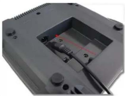
natural_image
Close-up of a black electronic device casing with visible internal components and a red measurement line (no text or symbols)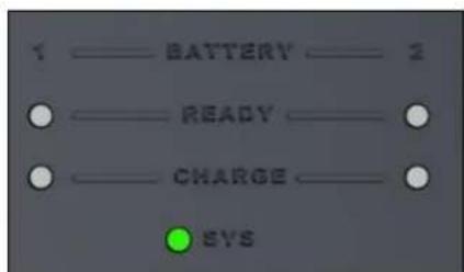
Recommendation for use:
Make certain that the system LED illuminates green.
INSERTING THE BATTERIES
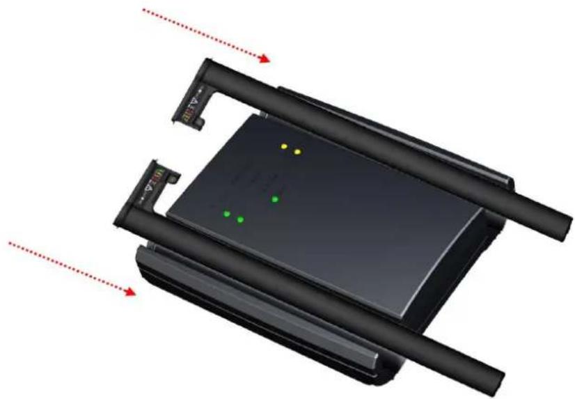
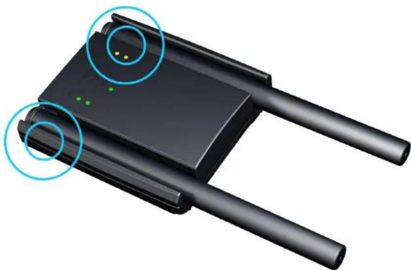
Insert the batteries into the battery slots so that there is a connection between the charging contacts of the battery charging station and the batteries.
natural_image
3D diagram of a device with green dots and red arrows indicating motion or movement, no readable text or symbols present.
Recommendation for use:
If the battery was correctly inserted in the battery charging station, an audible signal sounds and the charging process begins. An audible signal also sounds when a battery is removed.
natural_image
3D illustration of a black electronic device with two leads and a central display, showing two circular annotations highlighting points (no text or symbols present)LED STATUS INDICATORS
Various system activities are indicated during operation.
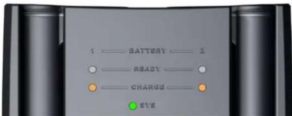
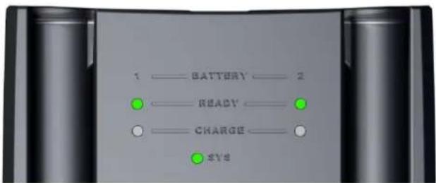
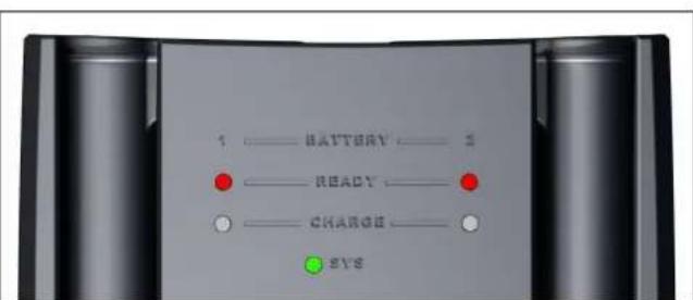
| READY LED INDICATOR | BEHAVIOUR | DESCRIPTION |
| - | No battery inserted | |
| Static | Battery fully charged | |
| Static | Battery is faulty | |
| CHARGE LED INDICATOR | ||
| - | Battery is not charging | |
| Flashing | Battery is charging | |
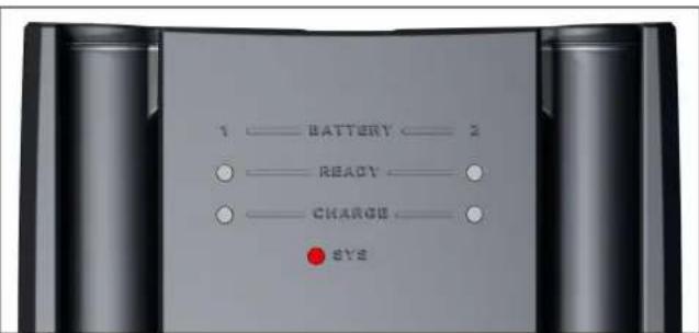
| SYS LED INDICATOR | ||
| Device is not connected to any voltage source (power supply/battery) | ||
| Static | Device is connected to a power source (power supply/battery) and switched on. | |
| Static | Device not ready for operation / defective power supply |
PICTOGRAPHIC REPRESENTATION
Battery is charging
text_image
1 —— BATTERY —— 2 ○ —— READ —— ● —— CHARGE —— ● SYSBattery fully charged
Device is not ready for operation / defective power source
text_image
1 —— BATTERY —— 2 ● —— READY —— ● —— CHARGE —— ● SYSBattery is faulty
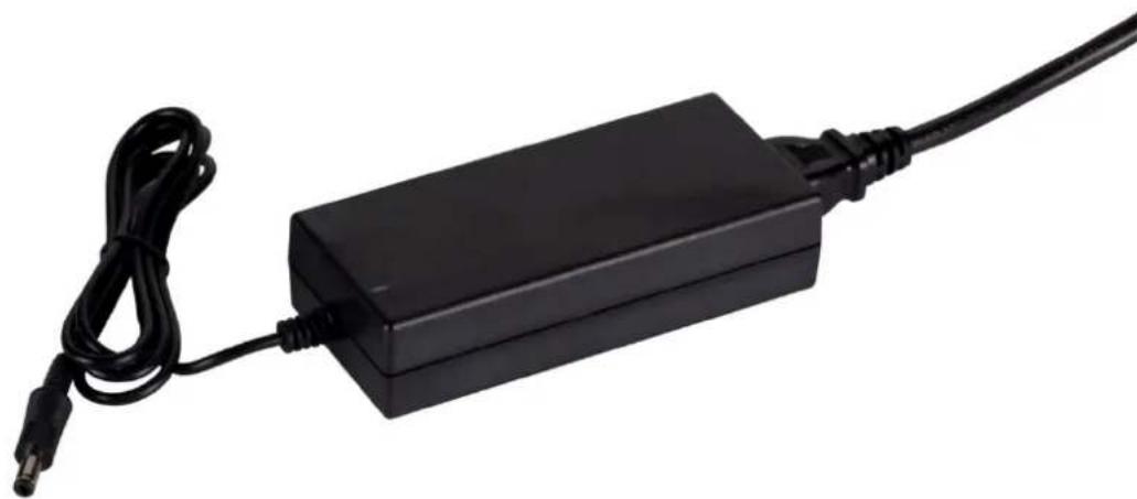
11.3 Replacement power adapter
A replacement power adapter is optionally available for operating the device (Article no.: DV-ITCOPT-004 001-AA).
Please note: This is a UL-certified accessory.
natural_image
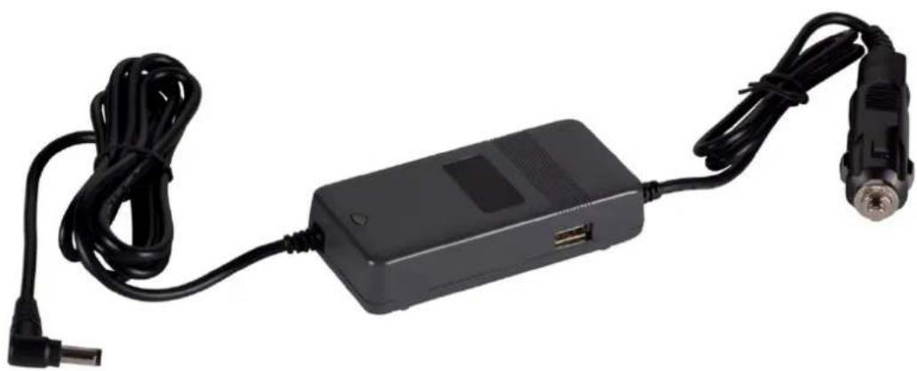
Black rectangular electronic device with a cable and connector, no visible text or symbols11.4 Vehicle power adapter
A vehicle power adapter is optionally available for operating the device (Article no.: DV-ITCOPT-005 001-AA). This can be used to conveniently supply the device with power in vehicles.
Please note: The vehicle power adapter is not a UL-certified accessory.
natural_image
Black electronic device with attached cable and connector, no visible text or symbolsTechnical data of the power adapter
• Power consumption: 90 watts
• Input voltage: 11-15 VDC
• Output voltage: 20 VDC
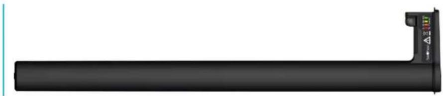
11.5 Replacement stick-type battery
A replacement battery is optionally available for operating the device (Article no.: DV-ITCOPT-003 001-AA).
natural_image
Illustration of a black cylindrical device with a small control panel and indicator lights on the right side (no text or symbols)Please note: This is a UL-certified accessory.
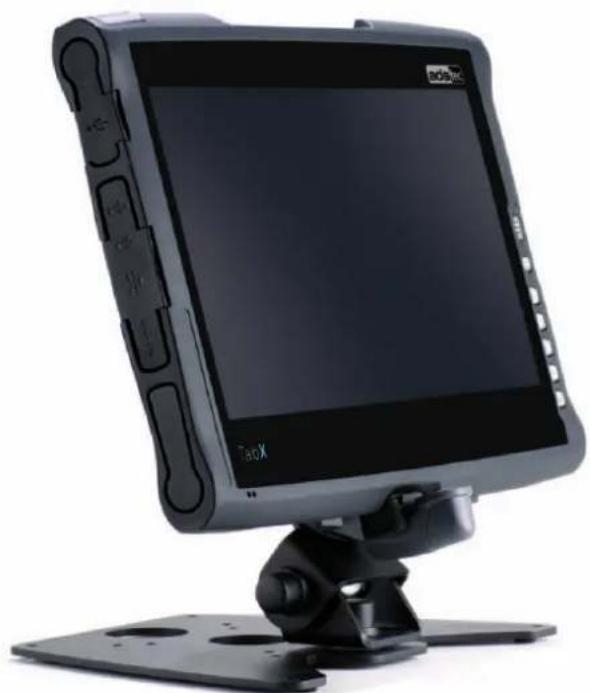
11.6 Rotatable and tiltable wall table adapter
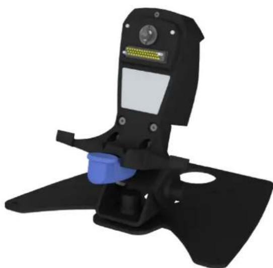
In combination with the table stand / wall bracket, the available docking station offers a stable mounting solution for every installation site. The device can be connected to the docking station using the docking connector on the rear side of the device.
Please note: This is a UL-certified accessory.
natural_image
Front view of a black Boosoft monitor with a stand and control panel (no visible text or symbols on the device body)The docking station is available in two versions. The first version is used strictly to hold the device. The second version (pictured) has a docking connector that transfers data to the interfaces of the docking station.
natural_image
3D model of a black handheld device with a blue handle and control panel (no text or symbols visible)Fastening the docking station to the stand / wall bracket
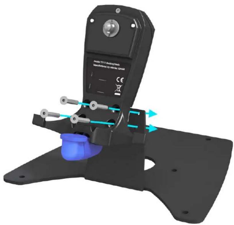
Tighten the screws contained in the scope of delivery as shown in the picture. Screws: M5x25, DIN 7991, strength 8.8, Allen key 3 mm, torque 1 Nm.
text_image
model TT13 Stacking Block Manufactured by Altelec GmbH CEFastening the bracket to a table or a wall
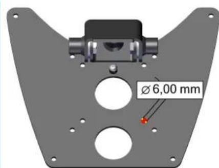
Use adequate screws and plugs depending on the load-bearing capacity of the supporting surface of the table or wall for safe mounting. The type of screw connection required (e.g. number, diameter, quality, type and length of screws and any special wall plugs or anchors required) depends largely on the fastening interface provided by the customer (e.g. on a steel plate, wooden plate or plasterboard). In case of doubt, have all necessary calculations carried out by an experienced designer.
text_image
Ø 6,00 mmMOUNTING THE DEVICE TO THE DOCKING STATION
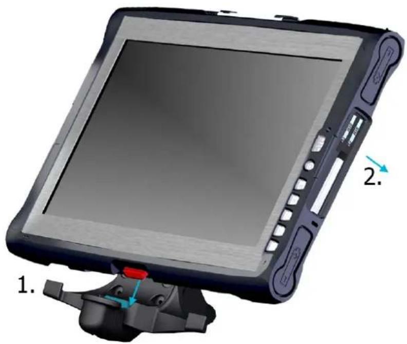
1) Place device on red marking behind the turquoise marking
2) Push device to the back onto the docking station. You should feel the device click into place
natural_image
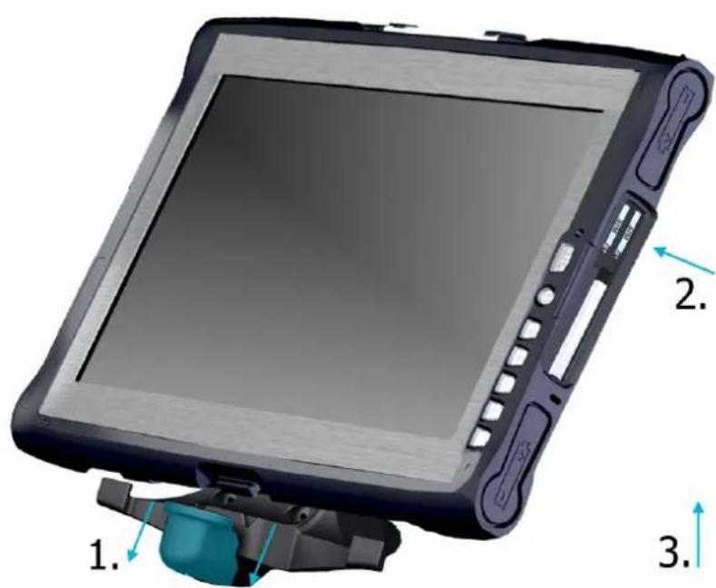
3D model of a tablet device with labeled parts (1 and 2), no visible text or symbols on the device itself.REMOVING THE DEVICE FROM THE DOCKING STATION
1) Push the turquoise release downward and hold down
2) Tilt the device forward slightly
3) Lift the device upward to disconnect and remove it from the docking station
text_image
1. 2. 3.The docking solution shown here illustrates the mechanical release. A lockable docking solution is also available.
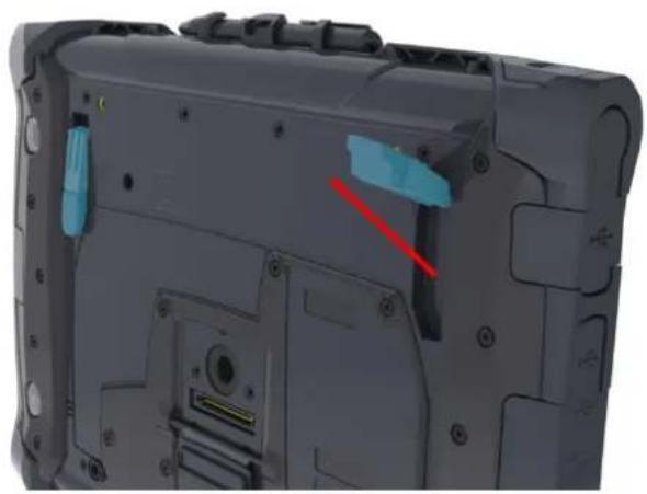
11.7 Tip-up feet
The tip-up feet enable comfortable operation anywhere.
natural_image
Close-up of a device rear panel showing internal components and a red arrow indicating a specific area (no text or symbols visible)11.8 3-point strap
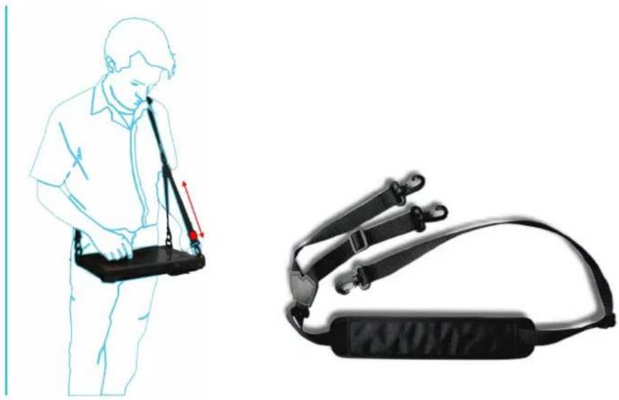
A 3-point strap is optionally available for mobile use. The 3-point strap can be mounted directly to the device and makes the device a mobile workplace.
Please note: The 3-point-strap is not a UL-certified accessory.
1 x DZ-MECH-33255-1 (A)
M5x16 flat-head screw, galvanised DIN 921

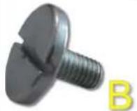
2 x DZ-MECH-33255-2 flat head screw. M5x20, galvanised DIN 921 (B)
3 x DZ-MECH-31033-0
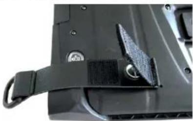
Strap eyelets
natural_image
Close-up of a black mechanical component with attached black band and mounting holes (no visible text or symbols)1 x DZ-MECH-31039-0
3-point strap
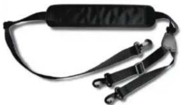
natural_image
Black safety harness with attached straps and belt (no text or symbols visible)MOUNTING THE 3-POINT STRAP TO THE DEVICE
1) First attach the strap eyelets to the device. In doing so, the appropriate mounting option must be selected for left- or right-handed users.

text_image
A B CE BLeft-handed users: white marking
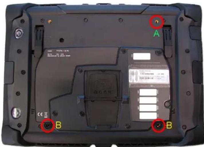
text_image
A B BRight-handed users: red marking
2) Screw down the strap eyelets at the marked positions as shown in the figure.
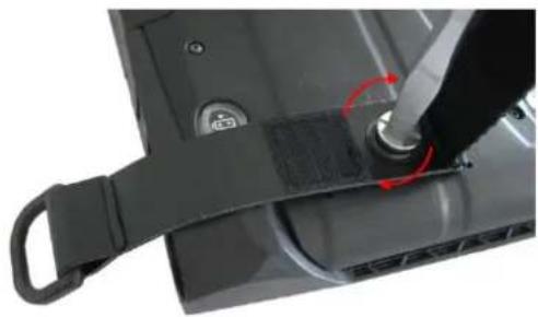
natural_image
Close-up of a black electronic device with a strap and screwdriver inserted, showing a red circular arrow indicating rotation (no text or symbols visible)
Recommendation for use:
Tighten the screws to max. 120 Ncm. The strap eyelets should still move without loosening the screw.
Mounted state for right-handed users
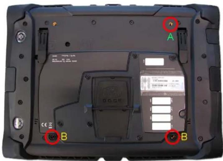
text_image
A B B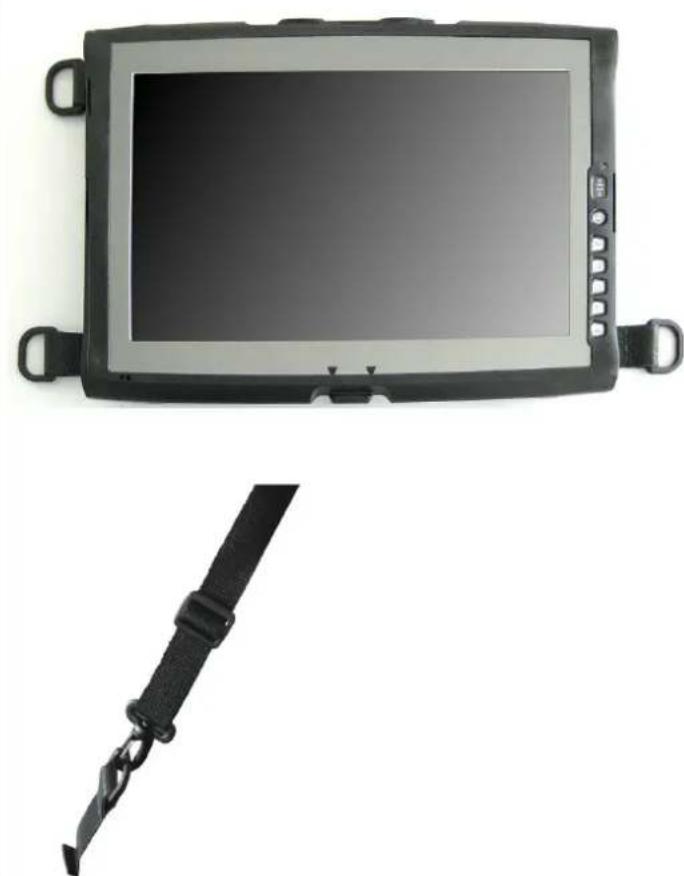
natural_image
Top-down view of a black rectangular electronic device with a screen and attached belt, shown against white background (no text or symbols visible)3) The shoulder strap can be attached to the strap eyelets via the carabiners. The device is ready for mobile use.

Recommendation for use:
The tilt adjustment of the shoulder strap (upper right) should always be attached to the upper side of the device.
11.9 Hand strap
As an alternative to the shoulder strap, a hand strap is available for mobile use. The hand strap can be mounted directly on the device and turns the device into a mobile workplace. Please note: This is a UL-certified accessory.
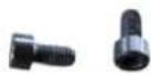
2 x supplied screws
1 x hand strap
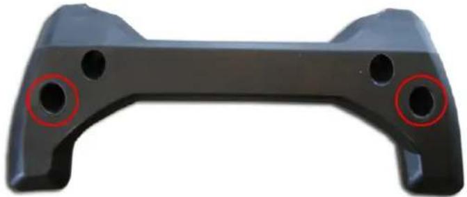
natural_image
Black game controller handle with two red circular holes, shown in side profile (no text or symbols)MOUNTING THE HAND STRAP ON THE DEVICE
1) The hand strap is to be mounted at the marked bore holes.
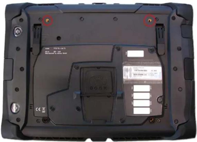
text_image
model P73152 / 08:15 DC-01 20V 1.5V Dissipation To Dissipation Doell DC-01 CE2) Screw down the hand strap at the marked positions as shown in the figure.
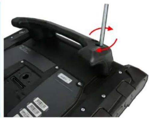
natural_image
Close-up of a black electronic device's rear panel showing a screwdriver inserted into a handle, with red arrows indicating motion (no text or symbols visible)
Recommendation for use:
Tighten the screws to max. 120 Ncm.
2) Mounted hand strap
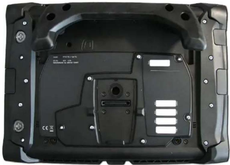
natural_image
Back view of a black electronic device casing with mounting hardware and internal components (no visible text or symbols)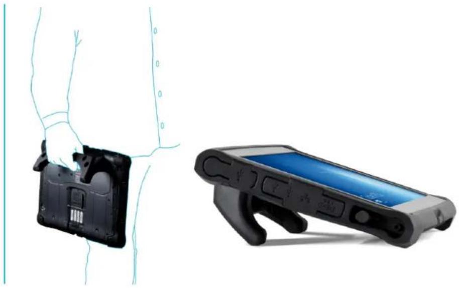
natural_image
Illustration of a person holding a device with a black plastic case and a black handheld device (no text or symbols visible)11.10 Protection cover
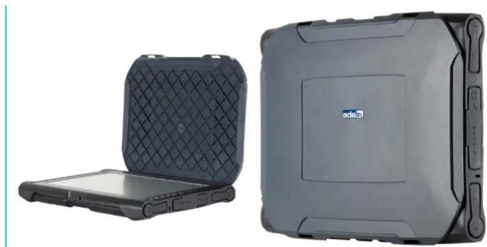
The optionally available protection cover offers protection against transport damages.
natural_image
Two electronic devices: a flat case with a grid-patterned cover and a black electronic device labeled 'adei' (no visible text or symbols on the device body)Please note: The 3-point-strap is not a UL-certified accessory.
12 Component replacement
ATTENTION
Make certain that all cables are disconnected and that no voltage is connected to the device!
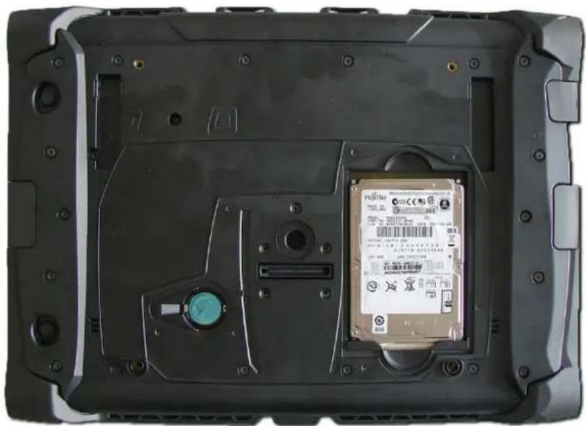
12.1 Opening the service slot
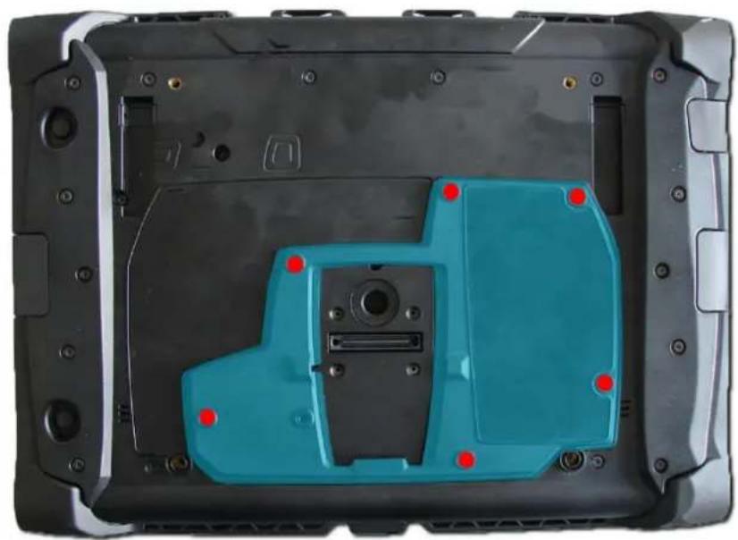
Remove the six screws for the service slot on the rear of the device.
The screws can be removed with a size Tx 8 screwdriver. The rear cover can be removed via the groove in the service slot on the bottom side.
natural_image
Top-down view of a black plastic device casing with blue internal components and red mounting points (no text or symbols visible)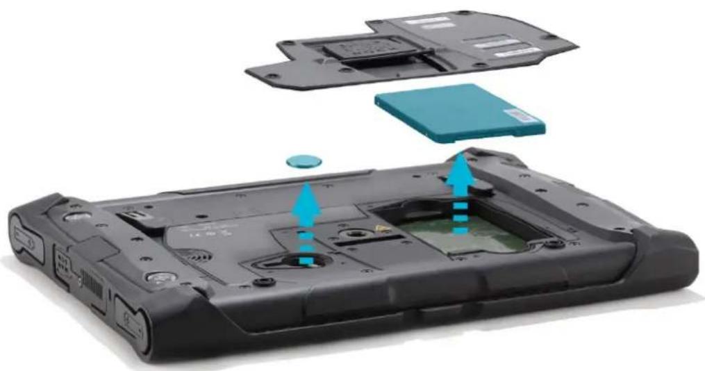
natural_image
Laptop case with internal components and blue arrows indicating assembly or installation (no text or symbols)By removing the service slot cover, it is possible to replace the following components.
1 HDD / SSD
2 Lithium battery
12.2 Changing the mass storage device
natural_image
Interior view of a black electronic device casing with a teal internal component and a red arrow indicating direction (no visible text or symbols)Removal
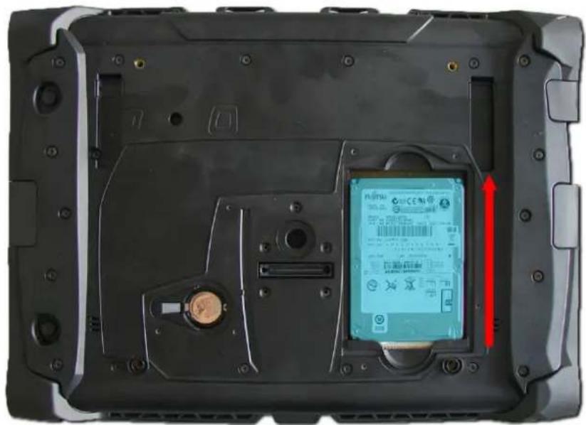
The extraction aid on the mass storage device should be used for removing. Pull out the storage medium.
Installation
The mass storage device must be carefully inserted into the slot and should noticeably engage.
12.3 Replacing the BIOS battery
natural_image
Back view of a black electronic device casing with internal components and a display panel (no visible text or symbols)The BIOS battery may only be replaced with a battery of the same type. The battery type to be used is:
Lithium battery CR2032 230mAh (make "VARTA")
(available under ADS-TEC part number: DZ-SONS-04075-1)
Ensure the correct polarity when inserting the battery.
ATTENTION
There is a risk of explosion if the battery is replaced with the wrong type or with the wrong polarity.
Observe the regulations for environmentally sound disposal of used batteries.
13 Service & support
ADS-TEC and its partner companies offer you comprehensive maintenance and support services, ensuring quick and competent support should you have any questions or concerns with regard to ADS-TEC products and equipment.
Because ADS-TEC products are also used by partner companies, these devices may have customised configurations. Should any questions arise with regard to such specific configurations and software installations, please contact the system supplier in question as ADS-TEC will not be able to answer such questions.
ADS-TEC does not provide support services for any device that was not purchased directly from ADS-TEC. In this case, maintenance and support is provided by the partner company.
13.1 ADS-TEC support
The ADS-TEC support team is available for inquiries from direct customers between 8:30am and 5:00pm, Monday to Friday.
The support team can be reached via phone, fax or e-mail:
Phone: +49 7022 2522-202
Fax: +49 7022 2522-400
Email: support@ads-tec.de
Alternatively, you can contact us by completing a support form on our website www.ads-tec.de.
Our Support team will then get in touch with you as soon as possible.