MMT8017 - Monitor ADS-TEC - Free user manual and instructions
Find the device manual for free MMT8017 ADS-TEC in PDF.


User questions about MMT8017 ADS-TEC
0 question about this device. Answer the ones you know or ask your own.
Ask a new question about this device
Download the instructions for your Monitor in PDF format for free! Find your manual MMT8017 - ADS-TEC and take your electronic device back in hand. On this page are published all the documents necessary for the use of your device. MMT8017 by ADS-TEC.
USER MANUAL MMT8017 ADS-TEC
text_image
Version 2.2 Translation of the original instruction manual Machine Mounted Terminal Machine Mounted TerminalInstruction manual
Machine Mounted Terminals /
Machine Mounted Displays
MMT8000 series / MMD8000 series
Read these instructions carefully before using and store for future reference.
These instructions contain important information about the product, in particular about its intended use, safety, installation, utilisation, maintenance and disposal.
Hand over the instructions to the user following installation of the product, and pass the manual on to the new user if the product is resold.
These instructions can be downloaded from: www.ads-tec.de in the Download area.
Publisher
1 Device description....6
2 General safety instructions 9
2.1 Information about documentation 9
2.1.1 General remark 9
2.1.2 Limitation of liability 9
2.1.3 Manufacturer and contact details 10
2.1.4 Relevant device documentation 10
2.1.5 Symbols 10
2.1.6 Data, figures and modifications 11
2.1.7 Trademarks 11
2.1.8 Copyright 11
2.1.9 Standards 11
2.2 Explanation of safety instructions 12
2.2.1 Structure of safety instructions 12
2.2.2 Explanation of signal words 13
2.3 Safety instructions 14
2.3.1 Basic safety instructions 14
2.3.2 Environmental conditions 14
2.3.3 Intended use 16
2.3.4 Improper use 16
2.3.5 Damage due to improper use 16
2.3.6 Warranty / repairs 17
2.3.7 Treatment and disposal of lithium batteries 17
2.3.8 Electrostatically sensitive components 18
3 Scope of delivery....19
3.1 Optional scope of delivery 20
4 Installation....21
4.1 Inclination angles 22
4.2 Overview of installation components 23
4.3 Order of installation 27
4.4 Installation with support arm adapter 28
4.4.1 Detaching support arm adapter from device 28
4.4.2 Key module 29
4.4.3 Adjusting position of support arm adapter 32
4.4.4 Preinstallation of connecting tube 34
4.4.5 Cable routing 36
4.4.6 Mounting support arm adapter on connecting tube 37
4.4.7 Detaching and attaching service slot cover 38
4.4.8 Mounting device on support arm adapter 40
.5 Installation with crosspiece adapter 41
4.6 Installation with VESA 75 adapter 42
5 Interfaces 44
5.1 Interfaces of machine mounted terminal 45
5.2 Interfaces of machine mounted display 48
5.2.1 Maximum cable lengths 50
5.3 Functional earthing 51
5.3.1 General informations regarding functional earthing 51
5.3.2 Functional earthing MMT 51
5.3.3 Functional earthing MMD without HDBaseT ^TM Extender Kit 52
5.3.4 Functional earthing MMD with HDBaseT ^TM Extender Kit 52
5.3.5 Functional earthing of accessories 53
6 HDBaseT™ Extender Kit....54
6.1 Installation of receiver module 54
6.2 Interfaces of receiver module 55
6.3 Connecting cables between receiver module and MMD 56
6.4 Interfaces of transmitter module 57
6.5 Status indicators 58
6.5.1 Status indicators on transmitter module 58
6.5.2 Status indicators on receiver module 59
7 Commissioning 60
8 Operation 62
8.1 Switching on and off 62
8.2 Multifunction touch-screen 62
8.3 Turning/tilting device and key module 63
8.4 Component replacement 65
8.4.1 Replacing BIOS battery on MMT8000 series 65
8.4.2 Replacing mass storage device 67
8.4.3 Replacement parts list 69
9 Maintenance, cleaning and disposal....70
9.1 Maintenance 70
9.2 Cleaning 70
9.3 Disposal 71
10 Nomenclature of ADS-TEC products and accessories....72
10.1 Main articles 72
10.2 Accessory articles 73
10.2.1 Display and USB transmission 73
10.2.2 Support arm adapter 74
10.2.3 Product kits 74
11 Technical data 75
11.1 MMT-MMD technical data 75
11.1.1 Data sheet 75
11.1.2 External device dimensions MMT8017 76
11.1.3 External device dimensions MMT8024 77
11.1.4 External device dimensions MMD8017 78
11.1.5 External device dimensions MMD8024 79
11.2 HDBaseT ^™ Extender Kit technical data 80
11.2.1 Data sheet 80
11.2.2 External device dimensions – HDBaseT™ Extender Kit transmitter 81
11.2.3 External device dimensions – HDBaseT ^™ Extender Kit receiver 82
12 List of figures....83
13 Service & support....85
13.1 ADS-TEC support 85
1 Device description
The Machine Mounted Terminal (MMT) and Machine Mounted Display (MMD) are designed for the control and visualisation of production processes in the pharmaceutical, foodstuff, beverage and chemical industry. In the case of the MMT, the processing unit is integrated in the housing, making an external PC unnecessary for control (Figure 1: Use of MMT and MMD). The MMD is a display which can be controlled by an external computer, e.g. from the existing industrial computer environment. With the MMD, cables can be used for distances of up to 15m between the display and computer. The optional HDBaseT™ Extender Kit has been developed to bridge greater distances of up to 100m . MMT and MMD are both available in the 17 and 24 inch format.
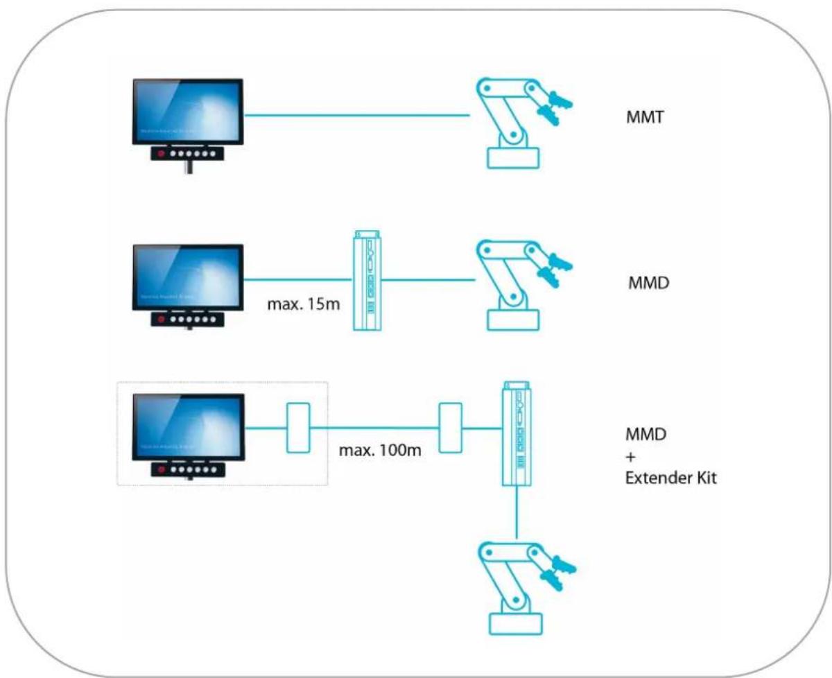
flowchart
graph LR
    A["MT"] --> B["Robot"]
    C["MT"] --> D["Robot"]
    E["MT"] --> F["Robot"]
    G["MT"] --> H["Robot"]
    I["MT"] --> J["Robot"]
    K["MT"] --> L["Robot"]
    M["Max. 15m"] --> N["Device"]
    O["Max. 100m"] --> P["Device"]
    Q["MMD"] --> R["Robot"]
    S["MMD + Extender Kit"] --> T["Robot"]
Figure 1: Use of MMT and MMD
The MMT/MMD8000 series has been specially developed to fulfil strict hygiene requirements. This is achieved by the stainless steel housing of the device being completely closed, having rounded edges and no external screws. This allows the device to be cleaned simply and effectively. The device has no fan, which means that the primary source of contamination is not present. Due to its robust, compact design, the device can also be operated under demanding environmental conditions. All necessary cables are routed to the device through the connecting tube so that there are no exposed cables in the operating room.
Thanks to the very latest multi-touch technology, the full-HD display with a maximum resolution of 1920x1080 pixels can be operated conveniently by touching and also by means of swiping and dragging movements. Operation with special gloves is also possible. Additionally, a freely configurable key module is available which enables e.g. individual production processes to be started and stopped by simply pressing keys or by operating a switch. An emergency-stop switch can also be integrated in this module.
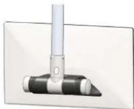
Both the MMT and MMD can be mounted either on a stand or on a support arm, i.e. stand or suspended mounting (Figure 2).
natural_image
Pure diagram of a mechanical component with no text, numbers, or symbols visible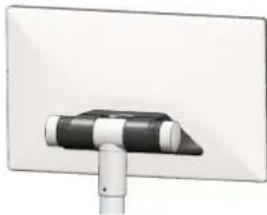
natural_image
Exterior view of a modern office building (no signage)Figure 2: Mounting on support arm and stand
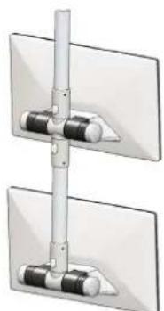
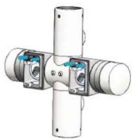
In addition to the T-piece support arm adapter, a crosspiece support arm adapter is also available (Figure 3). This allows two monitors to be mounted one above the other.
natural_image
Pure mechanical assembly diagram showing two vertical plates with a central rod and multiple cylindrical components (no text or symbols)Figure 3: Crosspiece adapter
By simply turning and tilting the device and the key module, each device can be adjusted during operation so that the user can view it at the optimum angle (Figure 4).
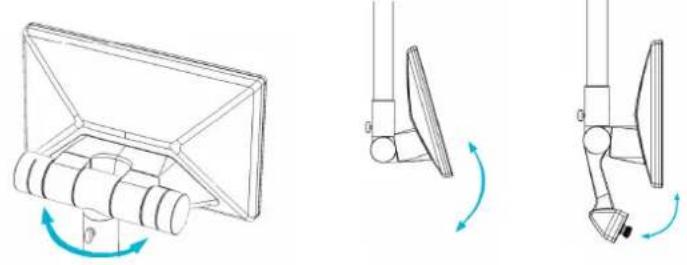
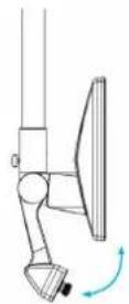
Figure 4: Turning and tilting
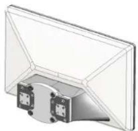
Alternatively, ADS-TEC also offers a VESA adapter which can be used to connect the device to a VESA 75 mounting system (Figure 5).
natural_image
3D technical illustration of a mechanical assembly with mounting brackets and housing (no text or symbols)Figure 5: VESA adapter
2 General safety instructions
2.1 Information about documentation
2.1.1 General remark
This instruction manual is intended to ensure safe and efficient handling and operation of IT Infrastructure products.
The instruction manuals must be read carefully by personnel before commencing any type of work.
All of the safety instructions and handling instructions given in the manual must be obeyed in order to ensure that work is carried out safely.
Operation of the system is subject to the laws and regulations which are applicable in the respective country at national, federal, European and international level.
The generally accepted rules of technology, usually in the form of standards, directives, regulations, conditions and technical rules specified by national and federal organisations as well as trade associations and committees for the field of specialisation concerned, shall apply.
Figures used in this instruction manual are provided for basic understanding and may differ from the actual design.
The operator/operating company is independently responsible for compliance with and observance of any subsequently introduced technical innovations or new legal requirements, as well as for all usual obligations of the operator/operating company.
The original version of this instruction manual was written in German. All non-German versions of this instruction manual are translations of the German instruction manual.
2.1.2 Limitation of liability
ads-tec Industrial IT GmbH shall not be liable for personal injury, property damage or damage caused to the device as well as consequential damage that is/was the result of non-compliance with this instruction manual, improper use of the device, repairs and other actions on the device by unqualified electricians and electricians not certified by ads-tec Industrial IT GmbH, or that is/was the result of using unapproved replacement parts. Failure to observe the maintenance intervals shall also result in exclusion from liability. Furthermore, it is strictly forbidden to make any unauthorised alterations or technical modifications to the device.
2.1.3 Manufacturer and contact details
The manufacturer of the product is ads-tec Industrial IT GmbH. The company is referred to in the following as ADS-TEC.
The following documents are decisive to device setup and operation:
- Instruction manual:
Contains information for installation, commissioning and operation of the device along with technical data of the device hardware.
- Website:
You can download the instruction manual as well as drivers, software, user manuals, leaflets and flyers from the Download area of our website www.ads-tec.de.
2.1.5 Symbols
Symbol Meaning
 | Designation of batteries in accordance with § 13 of the German Battery Act (BattG). Batteries may not be disposed of with household waste, but must rather be disposed of separately. Used batteries must be returned to the point of sale or a disposal system. |
 | Labelling of electrical and electronic devices in accordance with § 7 of the German Electrical and Electronic Equipment Act (ElektroG). Electrical and electronic devices must not be disposed of with household waste, but must rather be taken to a collection point for waste electrical equipment. Such a collection point is generally operated by public waste management authorities, i.e., by municipalities. |
 | Symbol for the functional earth connection |
2.1.6 Data, figures and modifications
All data, text and figures were prepared to the best of our knowledge. They do not represent any assurance for the properties themselves. Despite taking utmost care, no liability can be assumed for accuracy, completeness and actuality of the information. Subject to changes.
2.1.7 Trademarks
It is noted that any software and/or hardware trademarks and any company brand names mentioned in this documentation are all subject to the general trademark protection rights.
StoraXe®, Big-LinX® and X-Remote are registered trademarks of ADS-TEC.
All other used third-party trademarks are hereby acknowledged.
In the case of trademark infringement, ADS-TEC reserves the right to exercise all rights.
2.1.8 Copyright
This instruction manual is protected by copyright. For the authorised user, simple usage rights are granted within the scope of the intent of the contract. Any modified use or exploitation of the provided content, particularly duplication, modification or publishing in whatever form is permitted only with the prior consent of ADS-TEC.
In the case of copyright infringement, ADS-TEC reserves the right to exercise all rights.
2.1.9 Standards
CE
The manufacturer hereby declares that the product described in this instruction manual complies with all relevant stipulations of the following European directives:
• 2011/65/EU, RoHs Directive
• 2014/30/EU, EMC Directive
• 2014/53/EU, RED Directive
• 2014/35/EU, Low Voltage Directive
The product is a class B device.
Note: For full compliance with the EMC legislation, all components and cables used for device connection must also be compliant with these requirements. It is therefore necessary to employ BUS and LAN cables with shielded connectors and these must be installed as per the instructions contained in the instruction manual.
A corresponding EU conformity declaration is available for competent authorities at the manufacturer and can be viewed upon request.
The EU conformity declaration can be requested on our website www.ads-tec.de and downloaded in the Download area.
The product also complies with the following UL standards:
UL 61010-1 Programmable Controllers
UL 61010-2-201 UL file number E343358
CAN/CSA-C22.2 No. 61010-1
CAN/CSA-C22.2 No. 61010-2-201
2.2 Explanation of safety instructions
2.2.1 Structure of safety instructions
The signal word classifies the hazard.
Reference to the type/consequences and source of the hazard is made underneath the signal word. Information on how to avoid the hazard is indicated by an arrow (→).
DANGER

Type and source of the hazard!
Possible consequences if the hazard is disregarded
→ Measures for avoiding the hazard
2.2.2 Explanation of signal words
DANGER

Indicates an imminent danger.
If not avoided, death or severe injury will result.
WARNING

Indicates a possible danger.
If not avoided, death or severe injury could result.
CAUTION

Indicates a possible danger.
If not avoided, light or minor injuries could result.
ATTENTION
Indicates a possibly damaging situation.
If not avoided, the system or something in its surroundings could be damaged.

Recommendation for use:
Indicates terms and/or conditions that strictly need to be observed to ensure optimised and/or zero-defect operation. Tips and suggestions for the efficient use of the device and software optimisation are also provided.
2.3 Safety instructions
2.3.1 Basic safety instructions
- All users must read this manual and have access to it at all times.
- The safety notices and the manual itself must be observed by all persons who work with this device.
- The manual contains the most important instructions on how to use this device in a safe way.
- Intervention by the user is required only for performing the actions described in this document. Should any further modifications be required, it is necessary to consult either with the manufacturer directly or with service personnel authorised by the manufacturer.
- The device must be de-energised during work. Appropriate measures must be taken to prevent electrostatic discharges on components.
- If the device is opened up by an unauthorised person, the user may be subject to hazards and the warranty is invalidated.
- Installation, commissioning and operation may only be performed by qualified and trained personnel.
- At the installation site the valid guidelines and regulations for accident prevention must be observed.
- Appropriate storage, proper transport, installation and commissioning, as well as careful operation are prerequisites for ensuring safe and proper operation of the device.
- The device can be cleaned using cleaning agents specified in chapter 9.
2.3.2 Environmental conditions
ATTENTION
Damage caused by heat!
If the device is exposed to sunlight or any other light or heat source, it can overheat and suffer damage.
Do not expose the device to direct radiation by sunlight or any other light or heat source!
ATTENTION
Damage caused by heat!
If the device is installed in a panel, casing or similar, heat accumulation can occur.
→ Make sure that heat can be dissipated from the device!
ATTENTION
Damage caused by condensation!
If the temperature of the device is different to that of the room in which it is located, condensation can form.
Switch on the device only if it has acclimated to the ambient temperature!
Use of the device is only permitted
• in enclosed buildings
• in non-explosive atmospheres
• at altitudes below 2000 m
• in environments with maximum contamination grade 2 (IEC/EN 61131-2)
The device can be operated under the environmental conditions (temperature, humidity, vibration and shock) which are specified in the data sheet in chapter 10.1.1. Failure to observe any one of these conditions will invalidate the warranty of the device. ADS-TEC cannot be held liable for any damages arising from improper use and handling.
The climatic conditions were tested according to:
IEC/EN 60068-2-1
IEC/EN 60068-2-2
IEC/EN 60068-2-14
Protection class: IP65 according to DIN EN 60529
2.3.3 Intended use
The control system is designed for use in the pharmaceutical, food, beverage and chemical industries. It was specially developed for the hygiene sector. The device is used for the visualisation and control of a wide range of processes on systems and machines in various application environments.
The device is only to be assembled, installed and operated within the permissible specifications. Use in non-specified environments is prohibited.
2.3.4 Improper use
Operation other than or beyond that described for the device shall be deemed improper use.
The device is not allowed to be used to control vehicles or for applications for which further approvals beyond the manufacturer's declaration are necessary, e.g. applications with explosion hazard, medical technology and shipping industry.
The device must not be put into operation in the case of transport damage or nonconformity with the specifications and, if necessary, must be taken out of operation in the case of changing conditions.
In the case of improper use, ADS-TEC shall not accept responsibility or liability for injury or damage that is directly or indirectly attributable to the handling of the device.
2.3.5 Damage due to improper use
ATTENTION
Risk of mechanical damage!
The device can be damaged as a result of unauthorised mechanical modifications.
→ Make sure that the device is not drilled, chiselled or perforated and its exterior shape and design is not modified in any way!
Should the control system have evident signs of damages caused, e.g., by transport, nonconformity with the specifications, improper operation and storage conditions or due to improper use or handling, the device must be shut down immediately. Ensure that it is secured against being started up accidentally.
2.3.6 Warranty / repairs
During the device warranty period, any repairs must only be performed by the manufacturer or by service personnel that has been authorised by the manufacturer.
2.3.7 Treatment and disposal of lithium batteries
WARNING

Hazard due to explosion
Danger of explosion if using incorrect battery types.
→ Use the battery type recommended by the manufacturer!
ATTENTION
Hazard due to thermal loads
The more the battery is exposed to higher temperatures, the faster it ages.
→ Operate the device within its specifications!
ATTENTION
Damage to the battery
Incorrect handling of the battery can cause it to be damaged or destroyed
Lithium batteries should not be exposed to fire, soldered, recharged, opened, short-circuited, reversed or heated above 100 °C and they should be disposed of properly as well as protected against sunlight, humidity and condensation!
This device contains a lithium battery for supplying the system clock with power as long as the supply voltage is not connected. The battery has a life cycle of 3-5 years depending on which load is applied.
The battery type to be used is:
Lithium battery CR2032 230 mAh
ADS-TEC part number: DZ-SONS-04075-1
The used lithium battery should be disposed of in accordance with local legal regulations.
2.3.8 Electrostatically sensitive components
ATTENTION
Damage due to electrostatically sensitive components
Damage to the device can be caused by electrostatic discharges.
All installation and service work performed on the device must be performed only under safe, secure and de-energised conditions!

Recommendation for use:
Always adhere to the safety measures applicable when handling components at risk of being damaged by electrostatic discharges.
The provisions of DIN EN 61340-5-1 / DIN EN 61340-5-2 apply.
3 Scope of delivery
ATTENTION
Damage to components containing soft parts!
If the soft material is subjected to a concentrated load, e.g., by placing it on a grating, irreversible impressions will form after some time.
→ Make sure that a suitable surface is provided when setting down the device on its display side, e.g. a clean, plane surface!
→ Please check that all of the following components are contained in the packaging.
MMT8000 series
| Device DVG-MMT8017 | orDVG-MMT8024 |
| 4-pin plug (power supply) | DZ-SONS-01222-1/* |
| Instructions for drilling template | DZ-HAND-91053-0/* |
| Drilling template (for support arm adapter) | DZ-MECH-32444-0/* |
| Installation aid (M3 Allen key) | DZ-MECH-33703-0/* |
MMD8000 series
| Device DVG-MMD8017 | orDVG-MMD8024 |
| 3-pole plug | DZ-SONS-00994-2 |
| Instructions for drilling template | DZ-HAND-91053-0/* |
| Drilling template (for support arm adapter) | DZ-MECH-32444-0/* |
| Installation aid (M3 Allen key) | DZ-MECH-33703-0/* |
3.1 Optional scope of delivery
Operating system (only with MMT8000 series)
Key module
| Key module | DO-001520 |
Additional elements for key module (for non-premounted key module)
| Front coversheet for key module | DZ-MECH-32391-0/* |
| Insert strip (silver) | DZ-MECH-32396-0/* |
| Insert strip (black) | DZ-MECH-32396-1/* |
HDBaseT™ Extender Kit (only with MMD8000 series)
| Transmitter module | DV-MMDEXT-TX |
| Receiver module | DV-MMDEXT-RX |
| USB cable | DZ-SONS-05647-0/* |
| HDMI cable | DZ-SONS-05646-0/* |
| Cable for power supply | DZ-SONS-09796-0/* |
4 Installation
ATTENTION
Damage caused by heat!
If the device is exposed to sunlight or any other light or heat source, it can overheat and suffer damage.
Do not expose the device to direct radiation by sunlight or any other light or heat source!

Recommendation for use:
At least 2 persons are required to install the device at the installation location.

Recommendation for use:
Before installing, make sure that all mechanical connections are fixed in place in the connecting tube system at the installation location.
The following tools are needed for installation:
Installation with support arm adapter
- 4 mm Allen key (1 x straight and 1 x angled)
• 2.5 mm Allen key - 3 mm Allen key
- 5 mm Allen key or Torx TX10
- 2 mm flap-tip screwdriver
• Wrench (spanner) 17 mm
Installation with VESA 75 adapter
- 4 mm Allen key
- 5 mm Allen key or Torx TX10
- 5.5 mm Allen key
4.1 Inclination angles
Inclination angles at support arm adapter or crosspiece adapter
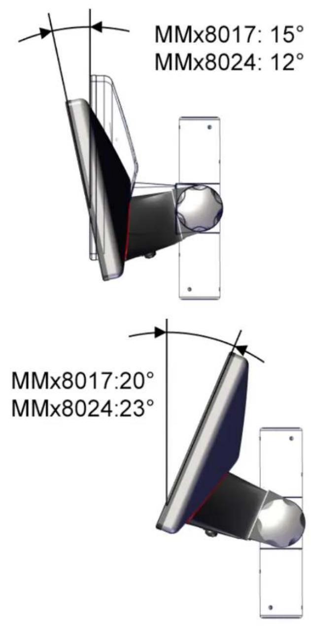
MMx8017:20°
MMx8024:23°
Figure 6: Inclination angles at support arm adapter or crosspiece adapter
4.2 Overview of installation components
Overview of screw connection to support arm adapter
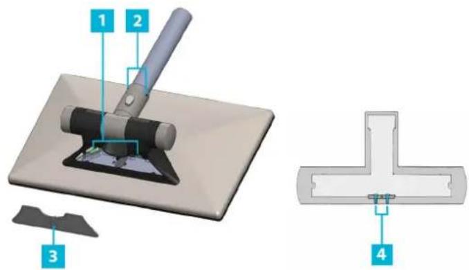
text_image
1 2 3 4Figure 7: Overview of screw connection to support arm adapter
1 4 mm Allen key, 6 Nm
2 3 mm Allen key, 6 Nm (important!)
3 5 mm Allen key or Torx TX10, max. 3 Nm
4 2.5 mm Allen key, max. 3 Nm
Overview of screw connection to VESA 75 adapter
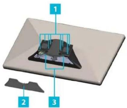
text_image
Diagram of a device with labeled components, showing a 3D model and parts marked 1, 2, and 3.Figure 8: Overview of screw connection to VESA 75 adapter
1 5.5 mm Allen key
2 5 mm Allen key or Torx TX10, max. 3 Nm
3 4 mm Allen key, 6 Nm
Designations
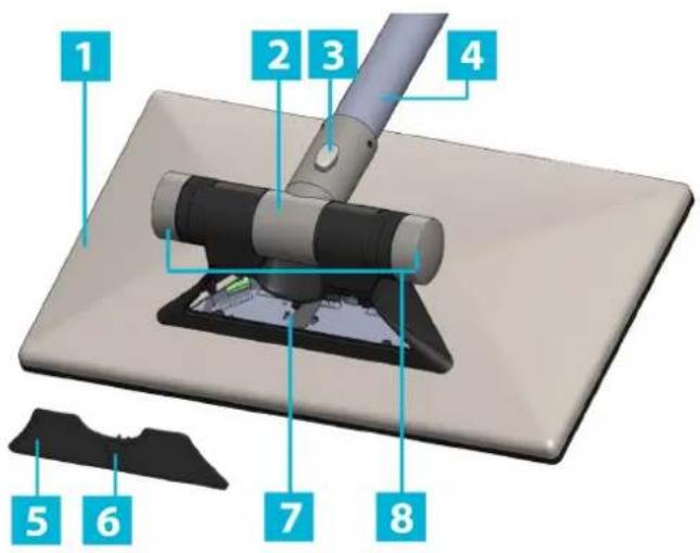
text_image
1 2 3 4 5 6 7 8Figure 9: Designations
1 Device
2 Support arm adapter
3 Wing screw
4 Connecting tube
5 Service slot cover
6 USB flap
7 Service slot
8 Fastening screws
Service slot – MMT8000 series
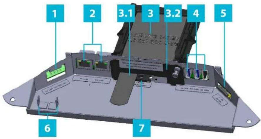
text_image
1 2 3.1 3 3.2 4 5 6 7Figure 10: Service slot – MMT 8000 series
1 Power supply
2 2 x LAN RJ45
3 1 x 2.5" SSD mass storage
3.1 Removal aid
3.2 Cover plate with screw fastening
4 2 x USB 3.0
1 x USB 2.0
5 1 x SD-Card Slot
6 2 x FE connection
7 Battery
Service slot - MMD8000 series
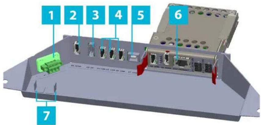
text_image
1 2 3 4 5 6 7Figure 11: Service slot – MMD8000 series
1 Power supply
2 1 x HDMI
3 1 x display port
4 3 x USB 2.0 type A
5 1 x USB 2.0 type B
6 Extender kit (optional)
7 2 x FE connection
4.3 Order of installation
Installation with support arm adapter
- Make sure that the device and all cables are disconnected from the power supply.
- Remove the support arm adapter from the device.
- Optional: Assemble and install the key module, chap. 4.3.2.
- Optional: Adjust the support arm adapter to the installation position you require, chap.4.3.3.
- Countersink the connecting tube, chap. 4.3.4.
- Guide all necessary cables through the connecting tube and support arm adapter, chap. 4.3.5.
- Mount the support arm adapter on the connecting tube (to 6 Nm), chap. 4.3.6.
- Optional: Slide the extender kit into the mounting slot and connect the cables, chap.6.
- Mount the device on the support arm adapter, chap. 4.3.8.
- Connect all cables to the interfaces in the service slot, chap. 5.
- Connect the device to the power supply (only after all of the above steps have been performed).
Installation with VESA 75 adapter
- Make sure that the device and all cables are disconnected from the power supply.
- Screw the VESA adapter to the device.
- Guide the cables through the VESA adapter, chap. 4.5.
- Mount the VESA adapter on your connection system.
- Connect all cables to the interfaces in the service slot, chap. 5.
- Connect the device to the power supply (only after all of the above steps have been performed).
4.4 Installation with support arm adapter
If you do not intend to use a support arm adapter, you can skip chapter 4.3.
4.4.1 Detaching support arm adapter from device

Recommendation for use:
If the support arm adapter is already attached to the device when delivered, remove it. This will make subsequent installation easier.
→ Loosen the four threaded pins (A) and remove the two screws (B).
→ Pull the support arm adapter off the device.
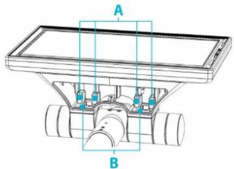
natural_image
Technical line drawing of a mechanical assembly with labeled components A and B (no text or symbols beyond labels)Figure 12: Screw connection of adapter to device
A 4 x M5 x 12 threaded pins (4 mm Allen key)
B 2 x M5 x 16 screws (4 mm Allen key)
4.4.2 Key module
→ If you do not intend to use a key module or if your key module has already been installed by ADS-TEC, you can skip chapter 4.3.2.
ATTENTION
Damage to key module
Opening the key module incorrectly can cause damage.
→ Open the key module on the right side (as viewed from the front)!
Switches, buttons and illuminated emergency-stop switches from various switch ranges can be installed on the key module for a hole diameter of 22.5 mm.
→ Determine the exact dimensions from the technical drawing.
→ Assemble and install the key module as described below:
→ Open the key module on the right side (as viewed from the front) using a wide, blunt object.
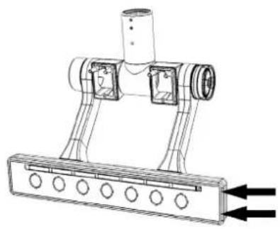
natural_image
Technical line drawing of a mechanical assembly with no visible text or symbolsFigure 13: Opening key module
→ Break the prepunched openings out of the key front as required. You can install up to seven switches/keys.
→ Punch the required ∅ 22.5 mm openings in the front coversheet from behind, or cut them out. The openings are highlighted in Figure 13.
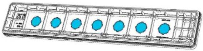
natural_image
Technical illustration of a rectangular enclosure with blue circular indentations and grid lines (no text or symbols)Figure 14: Prepunched openings in key module
→ Print or write the appropriate labelling on the insert strip.
The dimensions (given in mm) are shown in Figure 14. There are seven printable areas each measuring 6.5 mm in height and 40 mm in length. The gap on the left side is 11 mm and the gaps between the areas are 8.3 mm.

other
| Dimension | Value | | --------- | ----- | | Total Length | 6.5 | | Top Diameter | 0 | | Middle Diameter | 11 | | Bottom Diameter | 59.3 | | Left Diameter | 99.3 | | Right Diameter | 107.7 | | Middle Diameter | 247.7 | | Bottom Diameter | 156 | | Left Diameter | 156 | | Middle Diameter | 204.3 | | Bottom Diameter | 244.3 | | Left Diameter | 252.7 | | Right Diameter | 292.7 | | Middle Diameter | 301 | | Bottom Diameter | 341 | 360Figure 15: Labelling strip
→ Slide the labelling strip from behind into the key front.

text_image
20 A B TPE<<Figure 16: Inserting labelling strip
→ Mount your keys on the key front.
→ Install all necessary cables at the front keys.
→ Guide the cables through the arms of the mounting bracket.
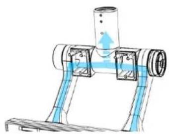
natural_image
Technical diagram of a mechanical assembly with blue structural elements and flow arrows (no text or labels)Figure 17: Cables of key module
→ Make sure that the key module electronics are earthed via the device.
Close the key module:
→ Position the front of the key module on the housing so that the panel lies against the left edge (as viewed from the front).
→ Press the front of the key module into the housing of the key module.
○ Make sure that the front is also properly pressed down at the middle of the housing.
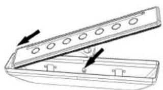
natural_image
Technical line drawing of a mechanical component with mounting holes and arrows indicating direction (no text or symbols)Figure 18: Closing key module
4.4.3 Adjusting position of support arm adapter
You can install the device both in the support arm position and in the stand position.
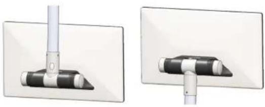
natural_image
Two technical diagrams showing a vertical pipe inserted into a black-and-white component, mounted on a white plate (no text or symbols present)Figure 19: Mounting on support arm and stand
If the support arm adapter is not already set to the desired position, adjust it as required. In order to do this, it is advantageous if the support arm is not connected to the device.
→ Loosen the screws marked in the drawing (4 mm Allen key).
→ Remove the screws and the clamping block from the support arm adapter, e.g. using a magnetic screwdriver. If the clamping block is jammed, turn in the installation aid (hexagonal rod with 3 mm grub screw, included in the scope of delivery).
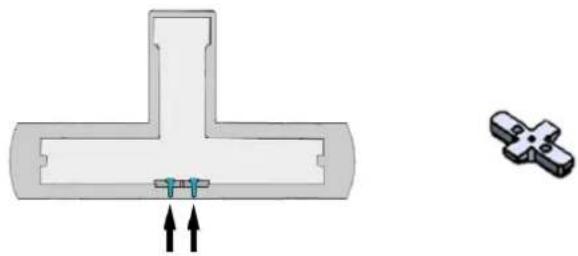
natural_image
Pure mechanical component diagram showing a T-shaped cross-section with two arrows pointing to a small internal component (no text or symbols)Figure 20: Screws in support arm adapter and clamping block
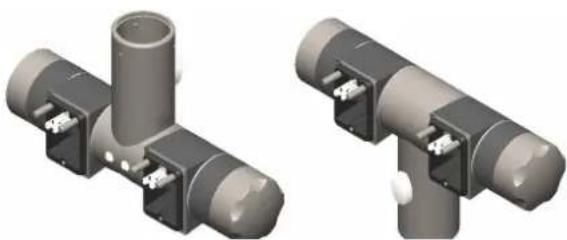
→ Grip the T-piece at one of the black areas and turn the metal tube to the other position. The support arm position (suspended mounting) is shown on the left and the stand position (stand mounting) is shown on the right:
natural_image
Two 3D renderings of gray mechanical T-junction connectors with white terminal blocks (no text or symbols)Figure 21: Support arm and stand position
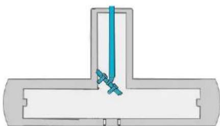
→ Loosely screw the rubberized side of the installation aid (rod with 3 mm threaded pins at the end) into the clamping block.
→ Insert the screws into the clamping block.
→ Guide the clamping block into the support arm adapter.
natural_image
Pure diagram of a T-shaped pipe joint with blue connectors, no text or symbols presentFigure 22: Inserting screws in adapter
→ Remove the installation aid.
→ Tighten the screws to a torque of 6.5 Nm (4 mm Allen key).
4.4.4 Preinstallation of connecting tube
WARNING

Risk of injury!
If the connecting tube is too thin, the device can work loose in the support arm position and fall to the ground.
→ Make sure that the connecting tube meets the specifications!
The connecting tube must have a diameter of 48.3 mm with a maximum tolerance of +/- 0.3 mm.
Support arm mounting
→ Attach the self-adhesive installation template to the end of the connecting tube.
- The "Display front" marking must be on the side on which the display will later be.
- The arrows must point to the end of the connecting tube.
- Attach the template to the connecting tube as far as the "Overlap" marking.
- Fold over the template at the "Folding edge" marking so that the end sticks to the back of the "Overlap" area.

text_image
3x 120° Senkung max.Tiele 2mm/ 3x 120°countersink max.depth 2mm Rohrende/ tube end pue eqn Rohrende/ tube end Display front pue eqn Rohrende/ tube end Oversteuern overhang Followwise fishing edgeFigure 23: Installation template
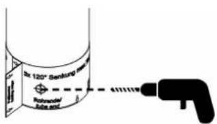
→ Countersink the connecting tube at the three marked points (min. M6 drill bit with 120° drill tip).
- Drill max. 2 mm deep.
text_image
Dr 120° Sertkong Rohminder Sitz und 4111119Figure 24: Countersinking connecting tube (support arm)
→ Remove the template.
Stand mounting
→ Attach the self-adhesive installation template to the end of the connecting tube.
- The "Display front" marking must be opposite the side on which the display will later be.
- The arrows must point to the end of the connecting tube.
- Attach the template to the connecting tube as far as the "Overlap" marking.
- Fold over the template at the "Folding edge" marking so that the end sticks to the back of the "Overlap" area.

text_image
3x 120° Sensing max Téra 2mm 3x 120° Counterink max depth 2mm Display front Rohrader Rohrader side end Rohrader side end Rohrader side end Rohrader side end Rohrader side end Rohrader side end Rohrader side end Rohrader side end Rohrader side end Rohrader side end Rohrader side end Rohrader side end Rohrader side end Rohrader side end Rohrader side end 3x 120° Sensing max Téra 2mm 3x 120° Counterink max depth 2mmFigure 25: Installation template
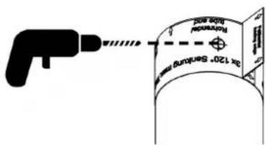
→ Countersink the connecting tube at the three marked points (min. M6 drill bit with 120° drill tip).
- Drill max. 2 mm deep.
text_image
2x 120 S###Figure 26: Countersinking connecting tube (stand)
→ Remove the template.
4.4.5 Cable routing

Recommendation for use:
Use cables long enough so that they hang out of the connecting tube by min. 30–35 cm.

Recommendation for use:
Route the cables according to the interface positions in the service slot.
Support arm mounting
→ Guide all cables out of the connecting tube and through the support arm adapter:
- Guide the USB cables through opening A.
- Guide the power supply cable, earth cable and LAN cable through opening B.
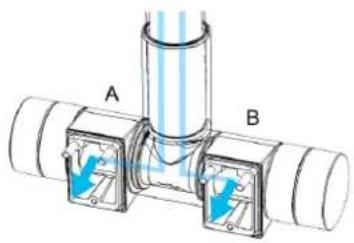
text_image
A BFigure 27: Cable routing for support arm mounting
Stand mounting
→ Guide all cables out of the connecting tube and through the support arm adapter:
- Guide the USB cables through opening A.
- Guide the power supply cable, earth cable and LAN cable through opening B.
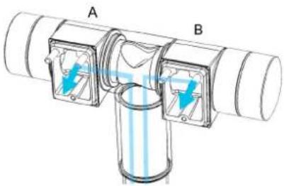
text_image
A BFigure 28: Cable routing for stand mounting
4.4.6 Mounting support arm adapter on connecting tube
WARNING

Risk of injury!
If the support arm adapter is attached too loosely, the device can work loose in the support arm position and fall to the ground.
→ Observe the specified torques!
Support arm mounting
→ Turn the foot of the support arm adapter so that the wing screw is opposite the connection openings.
→ Attach the support arm adapter to the tube.
- The connection openings must be on the side which the display is to face.
→ Screw in the three threaded pins of the support arm adapter to 6 Nm (3 mm Allen key).
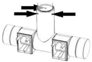
natural_image
Diagram of a T-junction pipe fitting with directional arrows indicating flow or movement (no text or symbols)Figure 29: Screwing adapter to tube (support arm)
Stand mounting
→ Turn the foot of the support arm adapter so that the wing screw is on the same side as the connection openings.
→ Attach the support arm adapter to the tube.
- The connection openings must be on the side which the display is to face.
→ Screw in the three threaded pins of the support arm adapter to 6 Nm (3 mm Allen key).
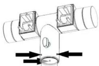
natural_image
Technical diagram of a pipe fitting with two valve components and directional arrows indicating flow or movement (no text or labels)Figure 30: Screwing adapter to tube (stand)
4.4.7 Detaching and attaching service slot cover
ATTENTION
Risk of dirt and moisture penetration!
If the USB flap is not closed completely, dirt or moisture can enter the device.
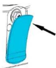
→ Close the USB flap completely before commissioning!
Removing service slot cover
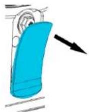
→ Open the USB flap
→ Undo the screw underneath (5 mm Allen key or Torx TX10).
natural_image
Illustration of a blue plastic bag attached to a curved pipe, with an arrow pointing to it (no text or symbols)Figure 31: USB flap
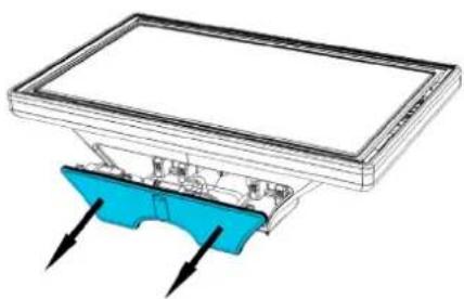
→ Remove the service slot cover.
natural_image
3D diagram of a rectangular electronic device with a blue base and black arrows pointing to its components (no text or symbols)Figure 32: Removing service slot cover
Attaching service slot cover
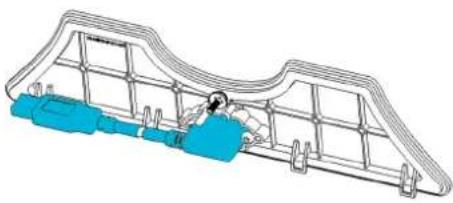
→ If required, insert the USB cable on the back of the service slot cover into the USB socket (USB 3.0).
natural_image
Technical line drawing of a mechanical assembly with blue components and grid lines (no text or symbols)Figure 33: USB cable on service slot cover
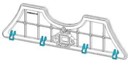
→ Position the lower edge of the service slot cover so that the retainer tabs engage in the frame.
natural_image
Technical line drawing of a mechanical component with blue connectors at both ends (no text or symbols)Figure 34: Retainer tabs of service slot cover
→ Tighten the mounting screw
- The service slot cover must be completely closed. The two sealing lips of the service slot cover must no longer be visible.
→ Close the USB flap.
natural_image
Illustration of a blue plastic bag attached to a curved pipe or sleeve, with an arrow pointing to it (no text or symbols present)Figure 35: USB flap
4.4.8 Mounting device on support arm adapter
WARNING

Risk of injury!
If a person attempts to install the device alone, it may fall to the ground causing injury and damage.
→ Have a second person assist in installing the device!
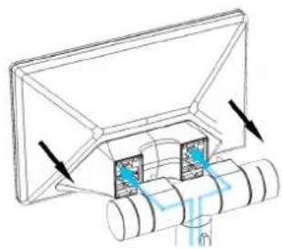
→ Hold the device in front of the support arm adapter.
→ Guide the cables out of the support arm adapter and through the service slot openings.
→ Mount the device on the support arm adapter.
natural_image
Technical line drawing of a mechanical assembly with arrows indicating motion or force (no text or symbols)Figure 36: Mounting device on adapter
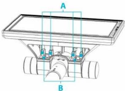
→ Screw on the device securely using the two screws B and the four threaded pins A.
natural_image
Technical line drawing of a mechanical assembly with labeled components A and B (no text or symbols beyond labels)Figure 37: Screwing device to adapter
A 4 x M5 x 12 threaded pins (4 mm Allen key)
B 2 x M5 x 16 screws (4 mm Allen key)
4.5 Installation with crosspiece adapter
The crosspiece adapter allows you to mount two devices one above the other.
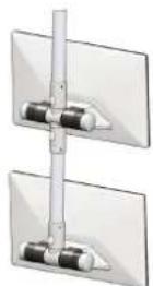
Figure 38: Installation with crosspiece adapter
→ Turn the two vertical tube sections of the crosspiece adapter so that the wing screws point away from the openings.
→ Countersink the connecting tube with the aid of a drill (see chap. 4.3.4).
- You can attach the adapter to a suspended tube (support arm mounting) or to a standing tube (stand mounting).
→ Guide the cables through the adapter.
natural_image
Cross-sectional diagram of a mechanical pipe fitting with internal components (no text or symbols)Figure 39: Crosspiece adapter
The upper side of the crosspiece adapter is the side with the four protruding metal pins (Figure 38).
- Route the cables according to the interface positions in the service slot (chap. 4.3.5).
→ Attach the crosspiece adapter to the connecting tube (chap. 4.3.6).
→ Open the service slot cover of the device (chap. 0).
→ Secure the device to the crosspiece adapter (chap. 4.3.8).
→ Connect the cables to the interfaces (chap. 5).
4.6 Installation with VESA 75 adapter
ATTENTION
Penetration of dirt!
If you route the cables through openings which do not match the cable diameters, dirt can enter through the opening.
→ Route the cables to the openings according to the diameter table given below!

Recommendation for use:
Route the cables according to the interface positions in the service slot.
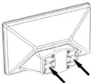
→ Screw the VESA adapter to the device.
To do so, secure using the four threaded pins and the two screws (chap. 4.3.8).
natural_image
Technical line drawing of a mechanical component with mounting holes and a bracket (no text or symbols)Figure 40: Device with VESA adapter
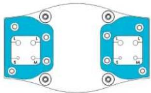
→ Remove the retainer plates (8 screws, 5.5 mm Allen key)
natural_image
Pure electrical circuit lines without any symbolsFigure 41: Retainer plates on VESA adapter
→ Open the service slot cover (chap. 0).
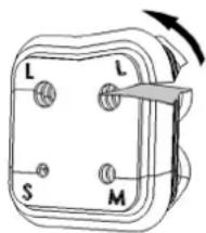
→ Push the rubber inserts upwards out of the bracket.
→ Pull out the sealing plugs at all cable glands that you require.
- To do so, pull the frame to the side (Figure 41).
- The sealing plugs attached to the rubber insert must NOT be cut off as they may be needed for modifications made later.
text_image
L L S MFigure 42: Rubber insert of VESA adapter
→ Guide the cables through the openings.
- For each cable, use the opening (S, M or L) which matches the cable diameter.
○ Diameter table:
S: = 2.4 - 4.0 mm
M: = 4.0 - 6.0 mm
L: = 6.0 - 7.4 mm
→ Press the rubber inserts into the bracket.
→ Screw on the retainer plates.
→ Screw the bracket to your VESA connection system.
- Screws M6, length depending on your system, lock washers etc.
- Maximum screw-in depth into the blind rivet nuts: 7 mm.
ATTENTION
Damage due to excessive tightening torque
The device can be damaged if the permitted tightening torque is not observed when the VESA bracket is screwed on.
→ Tighten the screws to max. 5 Nm.
→ If necessary: also use a suitable threadlocker, e.g., low-strength liquid adhesive.
5 Interfaces
WARNING

Hazard due to excessive current!
Excessive current can cause overloading of the electronics which could then result in injury or damage.
→ Operate the device with a power supply that complies with NEC Class 2!
ATTENTION
Damage to the electronics!
The electronics can be damaged if plug-in connections are connected or disconnected while power is still being applied.
→ Make sure that no power is being applied while connecting and disconnecting cables!
5.1 Interfaces of machine mounted terminal
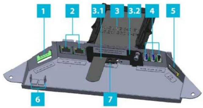
All device connections are in the service slot.
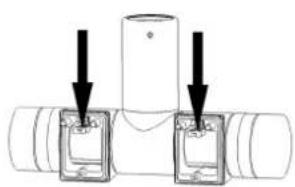
Strain relief fixtures are provided on the support arm adapter.
text_image
1 2 3.1 3 3.2 4 5 6 7Figure 43: MMT service slot
1 Power supply
2 2 x LAN RJ45
3 1 x 2.5" SSD mass storage
3.1 Removal aid
3.2 Cover plate with screw fastening
4 2 x USB 3.0
$$ 1 \times \text { USB } 2. 0 $$
5 1 x SD-Card Slot
6 FE connection (see chapter 5.3)
7 Battery
natural_image
Diagram of a T-junction pipe fitting with two connectors and arrows indicating assembly or connection points (no text or symbols present)Figure 44: Strain relief fixtures on support arm adapter
Power supply
You will need a power adapter with the following technical data:
Input voltage: 18 to 30 V (NEC Class 2)
Max. switch on current: 3 A (MMT8017)/4 A (MMT8024)
→ For the power supply, use only the 4-pole plug connector (see the scope of delivery, chap. 3).
1 Can be used for shutdown function of a UPS
| 2 0 V | --- |
| 3 | FE (see chapter 5.3) |
| 4 24 V | --- |
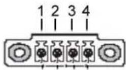
The figure shows the socket inside the device
USB
The sockets comply with the USB 2.0 standard (white interface) and the USB 3.0 standard (blue interfaces). The USB 2.0 interfaces are downward compatible to USB 1.0, and the USB 3.0 interfaces are downward compatible to USB 2.0 and USB 1.0.
LAN
You can integrate the device in an Ethernet network which supports 1 Gbit/s. For this purpose, use the 1Gbit RJ45 LAN ports. If required, the necessary drivers can be downloaded at www.ads-tec.de. The specifications for the network topology must be observed.
Mass storage
Hard disk / Flash SSD
The following storage options are available:
- mSATA module (permanently installed)
- 2.5" SSD mass storage with up to 500 GB via SATA (removable, see chapter 8.4.2)
External drives
External storage media can be connected via USB interfaces.
ATTENTION
Risk of data loss!
Data can be lost if an external data drive is connected or disconnected during operation.
→ Switch off the device before connecting or disconnecting an external data drive!
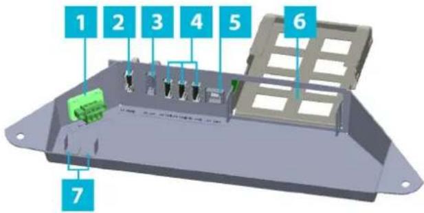
5.2 Interfaces of machine mounted display
All device connections are in the service slot.
Strain relief fixtures are provided on the support arm adapter.
text_image
1 2 3 4 5 6 7Figure 45: MMD service slot
1 Power supply
2 1 x HDMI
3 1 x display port
4 3 x USB 2.0 type A
5 1 x USB 2.0 type B
6 Mounting slot for extender kit
7 Earth connection (see chapter 5.3)
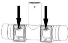
natural_image
Diagram of a T-junction pipe fitting with two connectors and arrows indicating assembly or connection (no text or symbols)Figure 46: Strain relief fixtures on support arm adapter
Power supply
You will need a power adapter with the following technical data:
Input voltage: 18 to 30 V--- (NEC Class 2)
Max. switch on current: 2 A (MMD8017)/2.5 A (MMD8024)
For the power supply, use only the supplied 3-pole plug connector (see the scope of delivery, chap. 3).
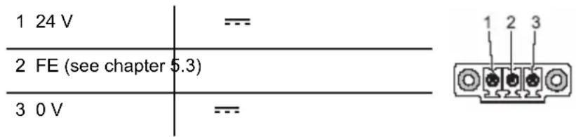
text_image
1 24 V --- 2 FE (see chapter 5.3) 3 0 V --- 1 2 3The figure shows the socket inside the device
USB
These interfaces comply with the USB 2.0 standard (3 x type A and 1 x type B). They are downward compatible to USB 1.0.
HDMI
The HDMI connection complies with version 1.4 of the HDMI standard.
Display port
The display port complies with version 1.2a of the VESA DisplayPort standard.
5.2.1 Maximum cable lengths

Recommendation for use:
Note the maximum cable lengths for the respective application type.
The maximum length of cables which can be used to connect the display and computer is:
- HDMI up to max. 15 m
• Display port up to max. 10m
• USB 2.0 up to max. 15 m
The HDBaseT™ Extender Kit (chap. 6) is required for greater distances between the display and computer. This kit can be ordered from ADS-TEC.
HDBaseT™ Extender Kit:
- HDBaseT™ up to max. 100 m
5.3 Functional earthing
5.3.1 General informations regarding functional earthing
• Functional earth (FE): For compliance with EMC regulations.
• Conductor cross sections:
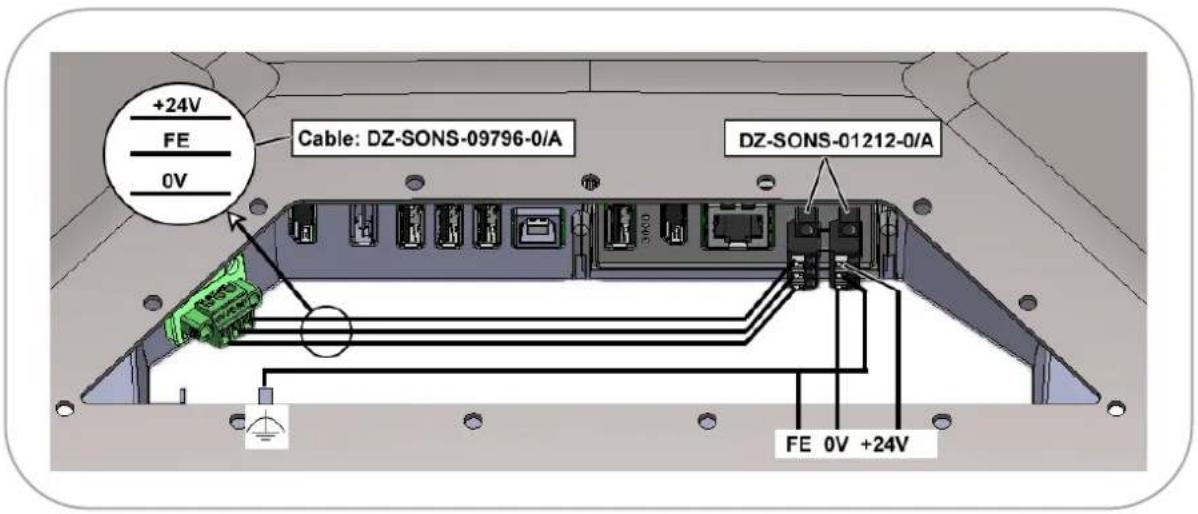
0V / FE / 24V: AWG 18 ( 1 mm ^2 ) or AWG 16 ( 1,5 mm ^2 ). With cable length > 5 m, use the larger cross section.
5.3.2 Functional earthing MMT
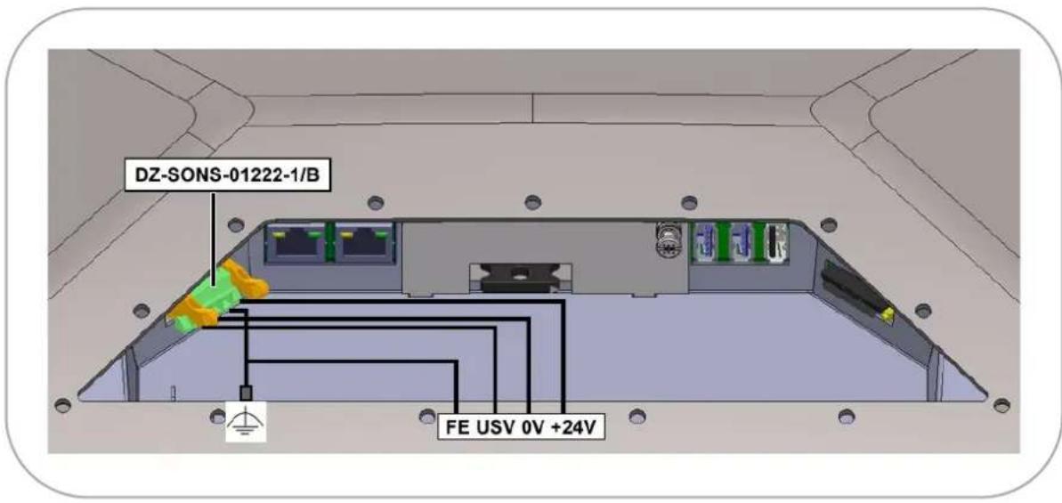
text_image
DZ-SONS-01222-1/B FE USV 0V +24VFigure 47: MMT – Functional earthing in the service slot
5.3.3 Functional earthing MMD without HDBaseT™ Extender Kit
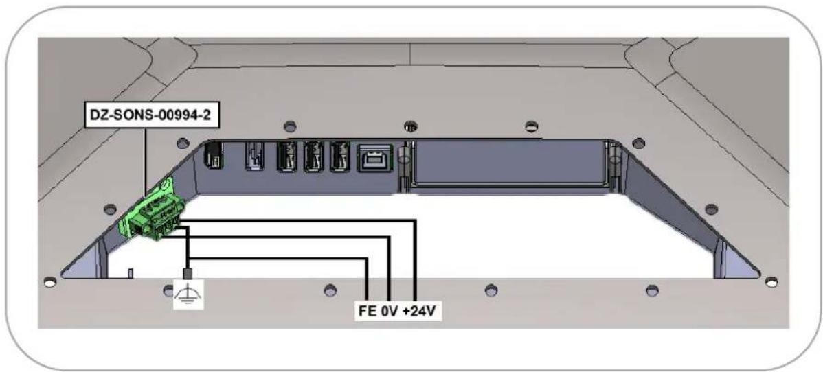
text_image
DZ-SONS-00994-2 FE 0V +24VFigure 48: MMD without HDBaseT Extender Kit – Functional earthing in the service slot
5.3.4 Functional earthing MMD with HDBaseT ^TM Extender Kit
text_image
+24V FE 0V Cable: DZ-SONS-09796-0/A DZ-SONS-01212-0/A FE 0V +24VFigure 49: MMD with HDBaseT Extender Kit – Functional earthing in the service slot
5.3.5 Functional earthing of accessories
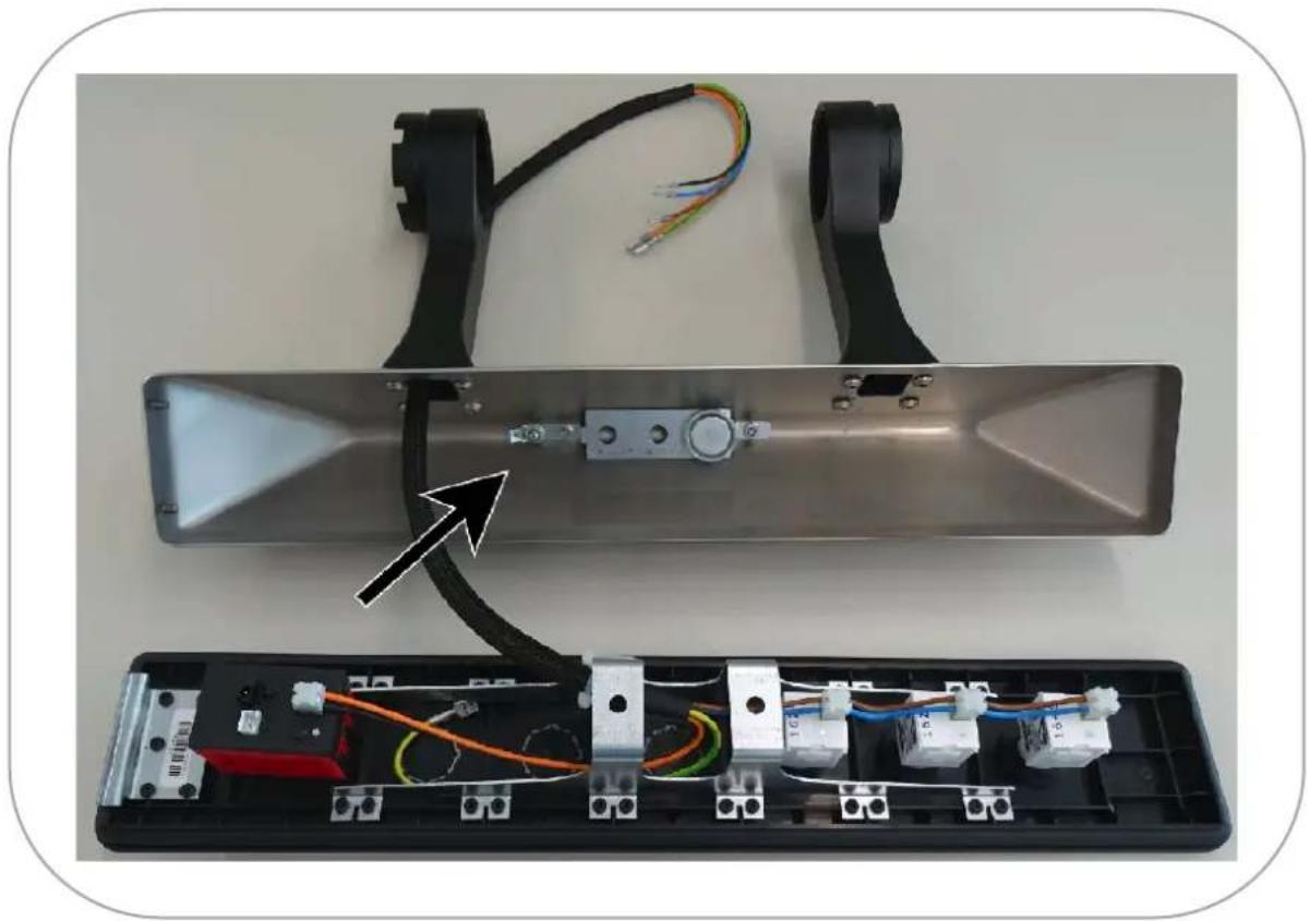
The following applies to the functional earthing of accessories, e.g. the optional key module:
- The earth connections of accessories and of MMD/MMT can be connected at the double clamp in the service slot.
natural_image
Interior view of an electronic device showing exposed wiring and components, with a black arrow pointing to a component (no text or symbols visible)Figure 50: Example: Earth connection of the optional key module
6 HDBaseT™ Extender Kit
WARNING

Hazard due to excessive current!
Excessive current can cause overloading of the electronics which could then result in injury or damage.
- Operate the device with a power supply that complies with NEC Class 2!
flowchart
graph LR
    A["MMD"] --> B["Receiver"]
    B --> C["HDBaseT"]
    C --> D["Transmitter"]
    D --> E["PC"]
    style A fill:#f9f,stroke:#333
    style E fill:#bbf,stroke:#333
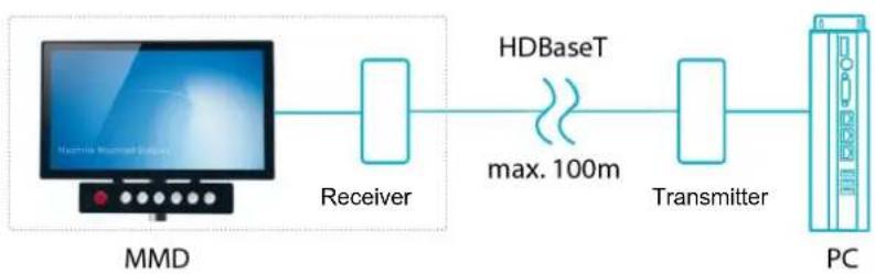
Figure 51: Use of HDBaseT™ Extender Kit
The HDBaseT™ Extender Kit allows data transmission between the computer and MMD over distances of up to 100 m. The scope of delivery is given in chapter 3.
6.1 Installation of receiver module
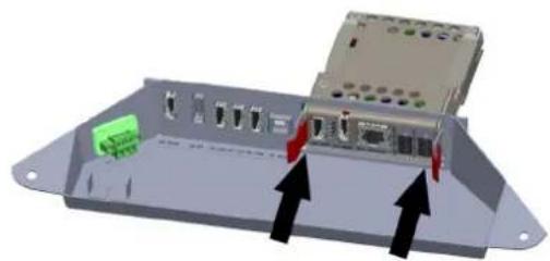
→ Open the service slot of the machine mounted display.
→ Slide the receiver module into the mounting slot.
- The catches of the two retainer tabs on the receiver module must engage in the retainer clips.
natural_image
3D rendering of an electronic device chassis with ports and connectors, showing two black arrows pointing to one component (no text or symbols visible)Figure 52: Receiver module in the service slot
6.2 Interfaces of receiver module
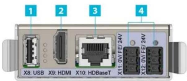
text_image
1 2 3 4 X8: USB X9: HDMI X10: HDBaseT X11: 0V/FE/24V X12: 0V/FE/24VFigure 53: Interfaces of receiver module
1 USB 2.0
2 HDMI
3 HDBaseT ^TM 100Mbit
4 2 x 24 V, connected in parallel
Power supply
To operate the receiver module, you will need a power adapter with the following technical data:
Input voltage: 18 to 30 V —— (NEC Class 2)
Max. switch on current: 0.8 A
If you intend to connect the MMD to the power supply via the receiver module (chap.0), you will need a power adapter with the following technical data:
Input voltage: 18 to 30 V--- (NEC Class 2)
Max. switch on current: 3.3 A
For the power supply, use only the supplied 3-pole plug connector (chap. 3).
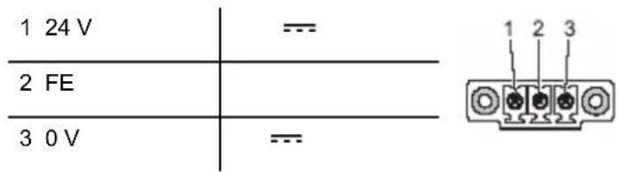
text_image
1 24 V --- 2 FE --- 3 0 V --- 1 2 3The figure shows the socket inside the receiver module.
6.3 Connecting cables between receiver module and MMD
→ When connecting and disconnecting cables, make sure that no power is being applied to the device or cables.

Recommendation for use:
Due to space constraints, connect the following cables before attaching the MMD to the bracket.

Recommendation for use:
Due to space constraints, connect the cables in the sequence given below.
→ Connect the power supply cable in order to supply the MMD with power via the receiver module.
→ Screw in the fastening screws of the connectors finger-tight.
→ Connect the USB cable.
→ Connect the HDMI cable.
nplete cabling:
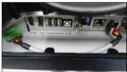
natural_image
Close-up of a computer interface showing internal components and cable connections (no visible text or symbols)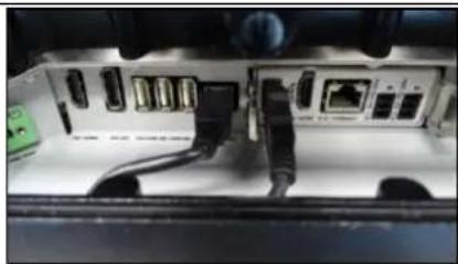
natural_image
Interior view of a device showing internal components including USB drive, network ports, and cable (no visible text or labels)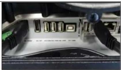
natural_image
Close-up of a computer monitor rear panel showing ports and buttons (no readable text or symbols)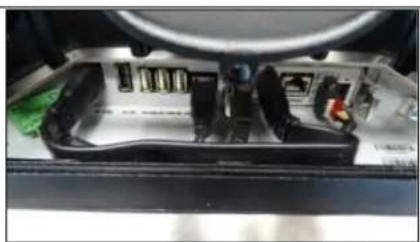
natural_image
Interior view of a mechanical device showing internal components and wiring (no visible text or symbols)6.4 Interfaces of transmitter module
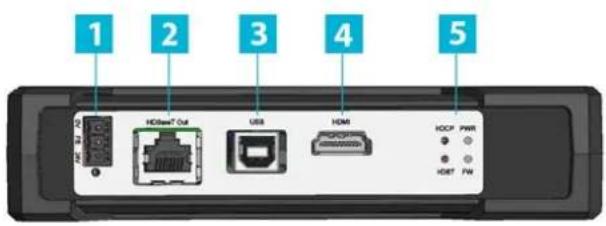
The transmitter module is intended for mounting on a top-hat rail (TS35) in the cabinet.
text_image
1 2 3 4 5 HDMI® Out USB HDMI HCCP PWR ● ○ ● ○ HDBF PNFigure 54: Interfaces of transmitter module
1 24 V ---
2 HDBaseT™ 100Mbit
3 USB 2.0
4 HDMI
5 SYS LEDs
→ Connect the receiver module to the transmitter module via the HDBaseT™ connection.

Recommendation for use:
The following CAT cables are recommended for connecting the transmitter to the receiver module: CAT6a cable 100 m with min. 24AWG / 27AWG
Power supply
You will need a power adapter with the following technical data:
Input voltage: 18 to 30 V (NEC Class 2)
Max. switch on current: 0.6 A
For the power supply, use only the supplied 3-pole plug connector (chap. 3).
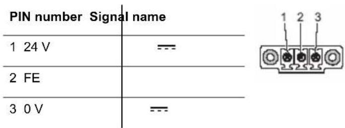
PIN number Signal name
| 1 24 V | --- |
| 2 FE | |
| 3 0 V | --- |
The figure shows the socket inside the transmitter module
6.5 Status indicators
6.5.1 Status indicators on transmitter module
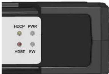
The transmitter module has LEDs which indicate the status of the transmitter. They provide information about the graphics link (HDCP), the power supply (PWR), the firmware (FW) and the HDBaseT™ connection (HDBT).
The table below lists the various states.
text_image
HDCP PWR HDBT FWFigure 55: Status indicators on transmitter module
LED signal Action
| HDCP | Flashing | Graphics link is present |
| Off | No graphics link | |
| PWR | On (blue) | The device is supplied with voltage via POWER and is ready for operation |
| Off | No power supply | |
| HDBT | On | HDBaseTTMlink present |
| Flashing slowly | Low Power Mode | |
| Flashing rapidly | Ethernet Fallback Mode | |
| Off | No link | |
| FW | Flashing | Firmware is loaded and ready for operation |
| Off | No firmware action |
6.5.2 Status indicators on receiver module
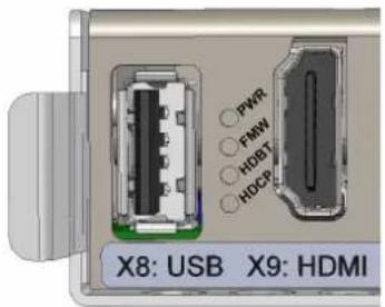
The receiver module has LEDs which indicate the status of the receiver. They provide information about the graphics link (HDCP), the power supply (PWR), the firmware (FW) and the HDBaseT™ connection (HDBT).
The table below lists the various states.
text_image
PWR PMW HDBT HOCP X8: USB X9: HDMIFigure 56: Status indicators on receiver module
Signal Action
| PWR | On (blue) | The device is supplied with voltage via POWER and is ready for operation |
| Off | No power supply | |
| FW | Flashing | Firmware is loaded and ready for operation |
| Off | No firmware action | |
| HDBT | On | HDBaseT^TM link present |
| Flashing slowly | Low Power Mode | |
| Flashing rapidly | Ethernet Fallback Mode | |
| Off | No link | |
| HDCP | Flashing | Graphics link is present |
| Off | No graphics link |
7 Commissioning
WARNING

Hazard due to excessive current!
Excessive current could result in injury or damage.
→ Operate the device only with a power supply that complies with NEC Class 2!
ATTENTION
Hazard due to excessive voltage!
The electronics can be damaged if the permissible voltage is exceeded.
→ Make sure to meet the permissible voltage for this device!
ATTENTION
Damage to the electronics!
The electronics can be damaged if plug-in connections are connected or disconnected while power is still being applied.
→ Make sure that no power is being applied while connecting and disconnecting cables!
ATTENTION
Damage to the electronics!
Condensation can damage the device.
→ Switch on the device only after it has acclimated to the ambient temperature!

Recommendation for use:
The shielding of a data cable must always be connected with the connector housing (EMC).

Recommendation for use:
Insofar as they are specified in the scope of delivery or in the replacement parts list, only connectors and cables offered by ADS-TEC are to be used for commissioning and during operation. All other connectors and cables which you use for commissioning and during operation must have been approved.
Check for operational readiness
→ Make sure that the screw connections between
- the device and support arm adapter
- the support arm adapter and connecting tube
are tightened to the specified torques.
→ Make sure that the service slot and the USB flap are completely closed.
Commissioning device
→ When connecting and disconnecting cables, make sure that no power is being applied to the device or cables.
→ Connect the cables to the interfaces in any order.
→ Secure the cables to the support arm adapter using the strain relief fixtures.
→ Make sure that the 24 V power supply complies with NEC Class 2.
→ Connect the device to the power supply.
8 Operation
8.1 Switching on and off
ATTENTION
Damage to the electronics!
The electronics can be damaged if the device is switched off and then on again too quickly.
→ After switching off and before switching on you must wait for at least 5 seconds!
→ Switch on the device by connecting it to the external power supply.
If an operating system (Windows or Linux) is installed, it now starts.
When the device is on, the status LED of the monitor lights up. This LED is on the front at the bottom right.
→ Switch off the device by shutting down the operating system.
8.2 Multifunction touch-screen

natural_image
Hand interacting with a blue abstract background (no text or symbols visible)Figure 57: Touch-screen
→ Operate the multifunction touch-screen using up to 10 fingers. It is not only possible to tap elements – swiping and dragging movements are also possible.

Recommendation for use:
The touch calibration data is stored independent of the operating system and requires no additional calibration by the user.
The necessary driver software is already integrated in the respective operating system.
If you need other drivers, you can download them at http://www.ads-tec.de in the Download area.

Recommendation for use:
With older operating systems, a driver may be required for the touch-screen functionality.
8.3 Turning/tilting device and key module
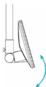
Tilting the device
→ Stand behind the device.
→ On the left side, unscrew the end cap provided with finger recesses approx. 3 turns.
→ Adjust the tilt of the device.
→ Screw down the end again.
natural_image
3D mechanical component with mounting holes and a blue arrow indicating direction (no text or symbols)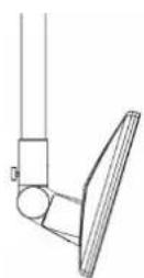
natural_image
Simple line drawing of a mechanical component with a curved arrow indicating rotation (no text or symbols)Figure 58: Tilting the device

Recommendation for use:
Make sure that the fastening screw of the support arm adapter is screwed out far enough so that the device moves smoothly. If rattling noises are heard when turning the device, unscrew the end further.
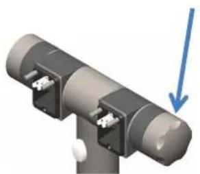
Tilting the key module
- Stand behind the device.
- Unscrew completely the end cap without finger recesses on the right side of the support arm adapter.
- Loosen the spacer sleeve with a suitable tool (width across flats: 17 mm).
- Adjust the angle of the key module.
- Tighten the spacer sleeve again.
- Screw down the end cap again.
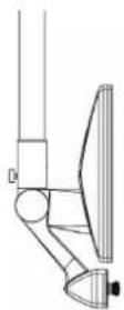
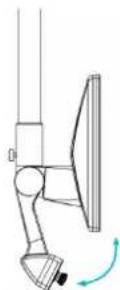
Figure 59: Tilting the key module
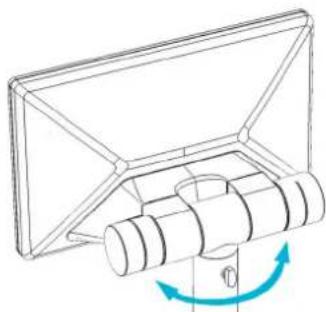
Turning the device
→ Undo the wing screw.
→ Turn the device (it can be turned through max. 340°).
→ Tighten the wing screw again.
natural_image
Pure mechanical diagram showing a rotating component with blue motion arrows, no text or symbols presentFigure 60: Turning the device
8.4 Component replacement
ATTENTION
Risk of short circuit!
A short circuit can occur if components are replaced while the device is still switched on.
→ Before replacing components, disconnect the power supply from the device!
8.4.1 Replacing BIOS battery on MMT8000 series
ATTENTION
Risk of explosion!
Hazard due to overheating of the battery
→ Make sure that the battery is of the correct type and that it is inserted with the correct polarity!

Recommendation for use:
Avoid touching both battery poles at the same time.
The device of the MMT8000 series contains a lithium battery for supplying the system clock with power as long as the supply voltage is not connected. The battery has a life cycle of 3-5 years depending on which load is applied. It is in the service slot (chap.0).
The battery type to be used is:
lithium battery type CR2032 (230 mAh / 3 V)

Recommendation for use:
Use only the battery type recommended by ADS-TEC.
Replacing battery
→ Pull out the battery drawer (pull both sides of the battery drawer at the same time).
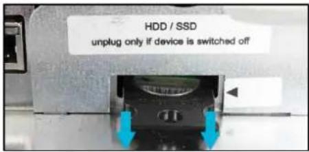
text_image
HDD / SSD unplug only if device is switched off→ Remove the old battery.
→ Press the new battery (1) into the drawer (2); the battery must engage in the drawer.
- The positive and negative terminal is indicated on the battery holder.

1 2
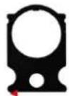
→ Turn the drawer (3) over so that the negative terminal is pointing upwards.
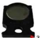
3
→ Insert the drawer into its slot (4); the drawer must engage in the slot.
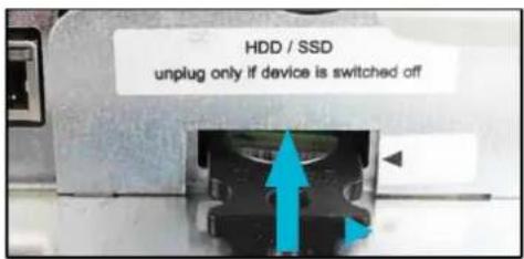
text_image
HDD / SSD unplug only if device is switched off8.4.2 Replacing mass storage device
On the MMT8000 series, there may be a mass storage device in the service slot (chap.0).
Removing mass storage device
→ Remove the cover plate.
- To do so, undo the fastening screw (PH1 cross-tip screwdriver).
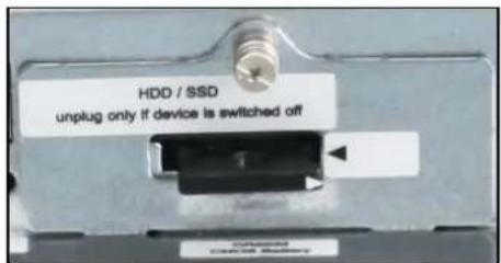
text_image
HDD / SSD unplug only if device is switched off→ Grip the mass storage device by its removal aid (white flap) and pull it carefully and parallel along its guides into the slot.
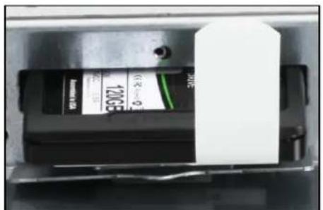
text_image
120°C (°C) (°C)→ Remove the mass storage device at an angle in an upward direction.
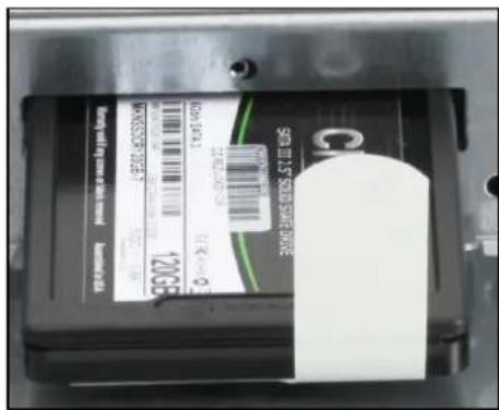
text_image
98.00元 USD 5.15 USD 3.48 USD 3.48 USD 3.48 USD 3.48 USD 3.48 USD 3.48 USD 3.48 USD 3.48 USD 3.48 USD 3.48 USD 3.48 USD 3.48 USD 3.48 USD 3.48 USD 3.48 EUR 120GB EUR 120GB EUR 120GB EUR 120GB EUR 120GB EUR 120GB EUR 120GB EUR 120GB EUR 120GB EUR 120GB EUR 120GB EUR 120GB EUR 120GB EUR 120GB EUR 120GB €98.00Installing mass storage device
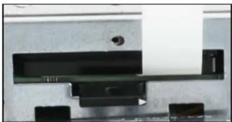
→ Insert the mass storage device into the slot at an angle.
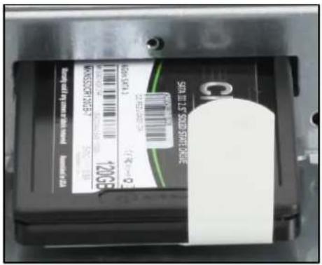
text_image
BARBING BAR BURGER 120GB 126.50000000 126.50000000 126.50000000 126.50000000 BARBING BAR BURGER BAR BURGER BAR BURGER BAR BURGER BAR BURGER BAR BURGER BAR BURGER BAR BURGER BAR BURGER BAR BURGER BAR BURGER BAR BURGER BAR BURGER BAR BURGER BAR BURGER BAR BURGER BAR BURGER BAR BURGER BAR BURGER BAR BURGER BAR BURG BAR BURG BAR BURG BAR BURG BAR BURG BAR BURG BAR BURG BAR BURG BAR BURG BAR BURG BAR BURG BAR BURG BAR BURG BAR BURG BAR BURG BAR BURG BAR BURG BAR BURG BAR BURG BAR BURG BAR BURS BAR BURS BAR BURS BAR BURS BAR BURS BAR BURS BAR BURS BAR BURS BAR BURS BAR BURS BAR BURS BAR BURS BAR BURS BAR BURS BAR BURS BAR BURS BAR BURS BAR BURS BAR BURS BAR BURS BAR BURRS BAR BURRS BAR BURRS BAR BURRS BAR BURRS BAR BURRS BAR BURRS BAR BURRS BAR BURRS BAR BURRS BAR BURRS BAR BURRS BAR BURRS BAR BURRS BAR BURRS BAR BURRS BAR BURRS BAR BURRS BAR BURRS BAR BURRS BAR BURRDSBGBGBGBGBGBGBGBGBGBGBGBGBGBGBGBGBGBGBGBGBGBGBGBGBGBGBGBGBGBGBGBGBGBGBGBGBGBGBGBGBGBGBGBGBGBGBGBGBGBGBGBGBGBGBGBGBGBGBGBGBGBGBGBGBGBGBGBGBGBGBGBGBGBGBGBGBGBGBGBGBGBGBGBGBGBBGBBGBBGBBGBBGBBGBBGBBGBBGBBGBBGBBGBBGBBGBBGBBGBBGBBGBBGBBGBBGBBGBBGBBGBBGBBGBBGBBGBBGBBGBBGBBGBBGBBGBBGBBGBBGBBGBBGBBGBB→ Lower the mass storage device and push it in all the way parallel to its guides.
natural_image
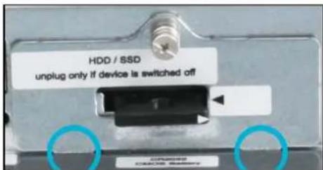
Close-up of a mechanical or electronic component with black components and a central black block (no visible text or symbols)→ Insert the retainer tabs of the cover into the guide slots and close the cover.
text_image
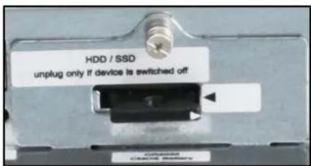
HDD / SSD unplug only if device is switched off→ Screw in the fastening screw finger-tight (PH1 cross-tip screwdriver)
text_image
HDD / SSD unplug only if device is switched off8.4.3 Replacement parts list
Insofar as they are specified in the scope of delivery or in the replacement parts list, only connectors and cables offered by ADS-TEC are to be used for commissioning and during operation. All other connectors and cables which you use for commissioning and during operation must have been approved.
The following components can be ordered as replacement parts from ADS-TEC:
Device/designation
Designation
Part number
MMT
| Plug | 4-pole plug with locking lever, green | DZ-SONS-01222-x |
| BIOS battery | Lithium battery CR2032 230mAh | DZ-SONS-04075-1 |
| FE cable connection | 6.35 mm blade terminal with retainer tab | DZ-HAND-36102-0 |
| Cable tie | Cable tie 98 x 2.5 mm, natural | DZ-HAND-03225-0 |
MMD
| Plug | 3-pole plug, black | DZ-SONS-01212-x |
| FE cable connection | 6.35 mm blade terminal with retainer tab | DZ-HAND-36102-0 |
| Cable tie | Cable tie 98 x 2.5 mm, natural | DZ-HAND-03225-0 |
Transmitter Tx
| Cable | USB2.0 1 m | DZ-SONS-05642-x |
| Cable | HDMI Male-Male 1 m | DZ-SONS-05643-x |
| Cable | HDMI Male-DP Male 1 m | DZ-SONS-05644-x |
| Plug | 3-pole plug, black | DZ-SONS-01212-x |
Receiver Rx
| Cable | 24 V --- power supply | DZ-SONS-09796-x |
| Cable | USB2.0 | DZ-SONS-05647-x |
| Cable | HDMI Male-Male | DZ-SONS-05646-x |
| Plug | 3-pole plug, black | DZ-SONS-01212-x |
9 Maintenance, cleaning and disposal
Maintenance and cleaning must be performed by appropriately qualified personnel.
9.1 Maintenance
The following maintenance intervals must be observed:
| Interval Location Activity | ||
| Daily | Overall device | Visually inspect for loose objects and visible damage |
| Monthly | Fixing screws | Check that they are seated securely; tighten as necessary |
| 3 years | BIOS battery | Change |
| Optional, if installed | ||
| Daily | Emergency stop button | Check that it functions correctly |
9.2 Cleaning
How often you need to clean the system depends on your work and the operating environment. If necessary, follow the on-site cleaning plan.
→ Clean and maintain your system regularly.
Cleaning agents and disinfectants
We recommend cleaning the devices using commercially available glass cleaning agents.
The following cleaning agents have also been successfully tested:
Ethanol and isopropanol based:
- Deconex Solarsept
- Bacillol
- Meliseptol
Neutral cleaning agents:
- P3-Cosa Foam 40
• P3-Cosa PUR 80
Disinfectants:
• Hydrogen peroxide < 30 %
Acidic cleaning agents:
- P3-cosa CIP 72
Quarternary ammonium compounds:
• Klerdice-CR Biocide A
- Deconex Surface AF
- P3-cosa DES
9.3 Disposal
Electrical and electronic devices must not be disposed of with household waste, but must rather be taken to a collection point for waste electrical equipment. Such a collection point is generally operated by public waste management authorities, i.e., by municipalities.
10 Nomenclature of ADS-TEC products and accessories
10.1 Main articles
A typical ADS-TEC article number is DVG-MMT8017 123-AB.
Many ADS-TEC article numbers for main products follow this logic:
- Starting letters until '-'
DV – hardware product without software
DVG – hardware product with software
DVK – kit; a combination of several products. Single products are normally also sold as DV or
DVG. Mainly used for customized bundles in large contracts.
- Three letters after ‘-’: describe product category, e.g.
MMD - Machine Mounted Display
MMT – Machine Mounted Terminal
OPD – Operating Panel Display
OPC – Operating Panel Computer
- First two digits: series, e.g. series 8000 is 80.
• Following two digits: size of screen, e.g. 17 for 17 inch and 24 for 24 inch. - Three digits after the blank: 123 or xxx is a continuous number between 001 and 999 and defines the system configuration.
- Last two letters: AB or yy are two varying letters depending on the operating system.
10.2 Accessory articles
10.2.1 Display and USB transmission
For distances up to 100m, a HDBaseT™ kit is available. It is named DVK-MMDEXT-KIT xxx-yy and contains two components:
• a receiver DV-MMDEXT-RX xxx-yy
• a transmitter DV-MMDEXT-TX xxx-yy
functionality is described in detail in chapter 6 of this document.
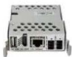
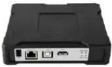
For distances less than 15m, HDMI and USB cables are available as an option. Their article numbers are e.g. DV-MMXOPT-04 xxx-yy.
Analogous to this, spare parts and additional small components are all named DV-MMXOPT-zz xxx-yy.
10.2.2 Support arm adapter
DVG-MMD80zz xxx-yy and DVG-MMT80zz xxx-yy can be mounted using the support arm adapter DV-MMXADAPT xxx-yy. Several versions of DV-MMXADAPT xxx-yy are available, the differences are indicated by xxx-yy. Examples for this are:
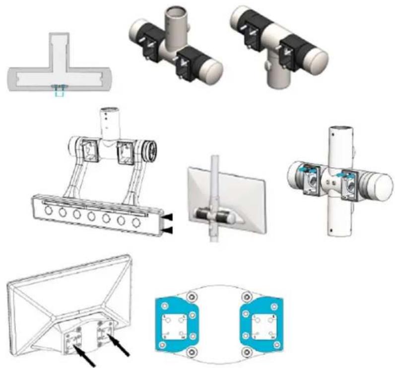
Front foils and keys can be customized, if this is done at ADS-TEC, this changes xxx-yy in the article number. Details are described in chapter 4.3.2.
10.2.3 Product kits
Combinations of several products are called kits and denoted by DVK in the article number. The single products are normally also sold as DV or DVG. This is mainly used for customized bundles in large contracts or for typical combinations that are useful for many customers.
Examples:
- DVK-MMDEXT-KIT xxx-yy contains a receiver DV-MMDEXT-RX xxx-yy and a transmitter DV-MMDEXT-TX xxx-yy.
- DVK-MMD8017 xxx.yy contains DVG-MMD8017 xxx.yy DV-MMDEXT-RX xxx-yy DV-MMDEXT-TX xxx-yy DV-MMXADAPT xxx-y
- Likewise, DVK-MMD8024, DVK-MMT8017, DVK-MMT8024, DVK-OPD8017 and DVK-OPD8024 are available.
11 Technical data
11.1 MMT-MMD technical data
11.1.1 Data sheet
| MMT8017 | MMT8024 | MMD8017 | MMD8024 | |
| Housing Fully enclosed stainless steel housing | ||||
| Display Resolution | 17.3" LED backlight 1920 x 1080 pixels | 23.8" LED backlight 1920 x 1080 pixels | 17.3" LED backlight 1920 x 1080 pixels | 23.8" LED backlight 1920 x 1080 pixels |
| Touch PCAP multi-touch / toughened glass | ||||
| Processor | Intel® CeleronTM1.6 GHz (2980U)orIntel® CoreTM i51.9 GHz (4300U) | - | ||
| RAM to 8 GB DDR3 - | ||||
| Mass storage | SSD to 500 GBormSATA SSD to 128 GB | - | ||
| Network | 2 x 1 Gbit/s Ethernet RJ45 | - | ||
| Interfaces | 1 x USB 2.0/2 x USB 3.0(1 x accessible from outside, optional) | 3 x USB 2.0 (1 x accessible from outside, optional)1 x USB slave1 x HDMI, 1 x display port | ||
| Power adapter 18 – 30 V --- NEC Class 2 | ||||
| Operating system | Windows Embedded Standard 7(64 bit)orWindows 7 Ultimate [for Embedded Systems](64 bit)orWindows Embedded 8.1 Industry Pro(64 bit)orWindows 10 IoT (64 bit) | - | ||
| Protection class IP65 (not verified by UL, tested by ADS-TEC) | ||||
| Operating temperature | 0 °C to +50 °C | 0 °C to +45 °C | 0 °C to +50 °C | 0 °C to +45 °C |
| Dimensions (W x H x D)(without support arm and key module) | 431 x 261 x 68 mm | 578 x 347 x 67 mm | 431 x 261 x 68 mm | 578 x 347 x 67 mm |
| Weight | Approx. 5 kg(without key module) | Approx. 7.5 kg(without key module) | Approx. 5 kg(without key module) | Approx. 7.5 kg(without key module) |
| Vibration 10 m/s2; 2 – 200 Hz (class 3M4 of standard IEC/EN 60721-3-3) | ||||
| Shock resistance 100 m/s2; t=11 ms (class 3M4 of standard IEC/EN 60721-3-3) | ||||
| Humidity 10 to 85% non-condensing | ||||
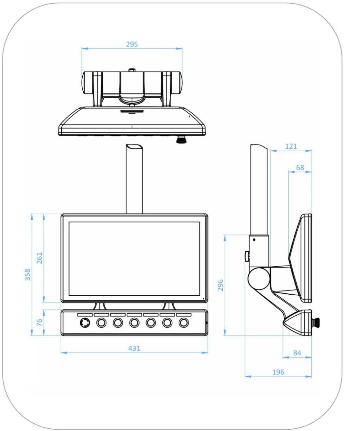
11.1.2 External device dimensions MMT8017
text_image
295 358 261 76 431 296 121 68 84 196Figure 61: External device dimensions MMT8017
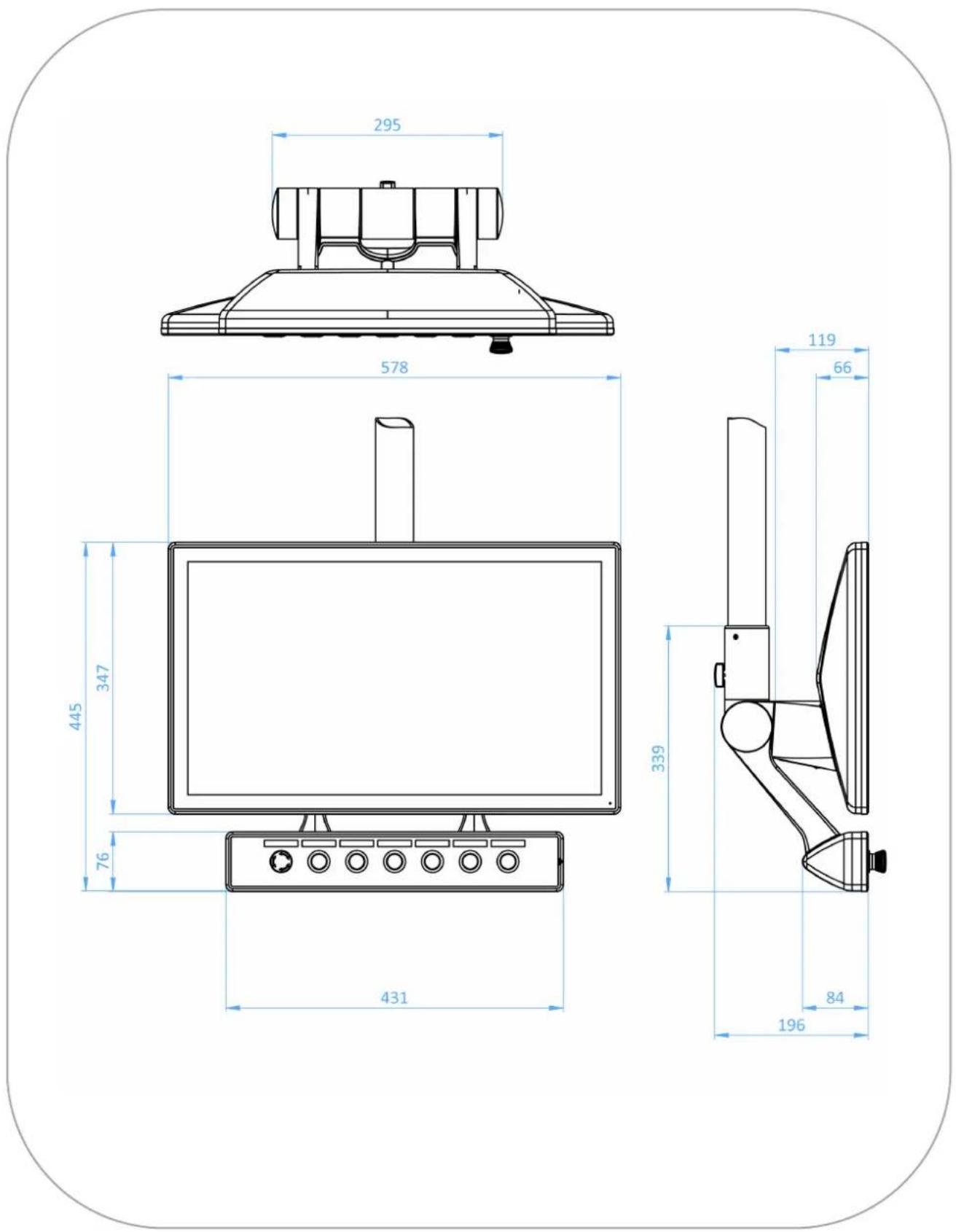
11.1.3 External device dimensions MMT8024
text_image
295 578 445 347 76 431 119 66 339 84 196Figure 62: External device dimensions MMT8024
11.1.4 External device dimensions MMD8017
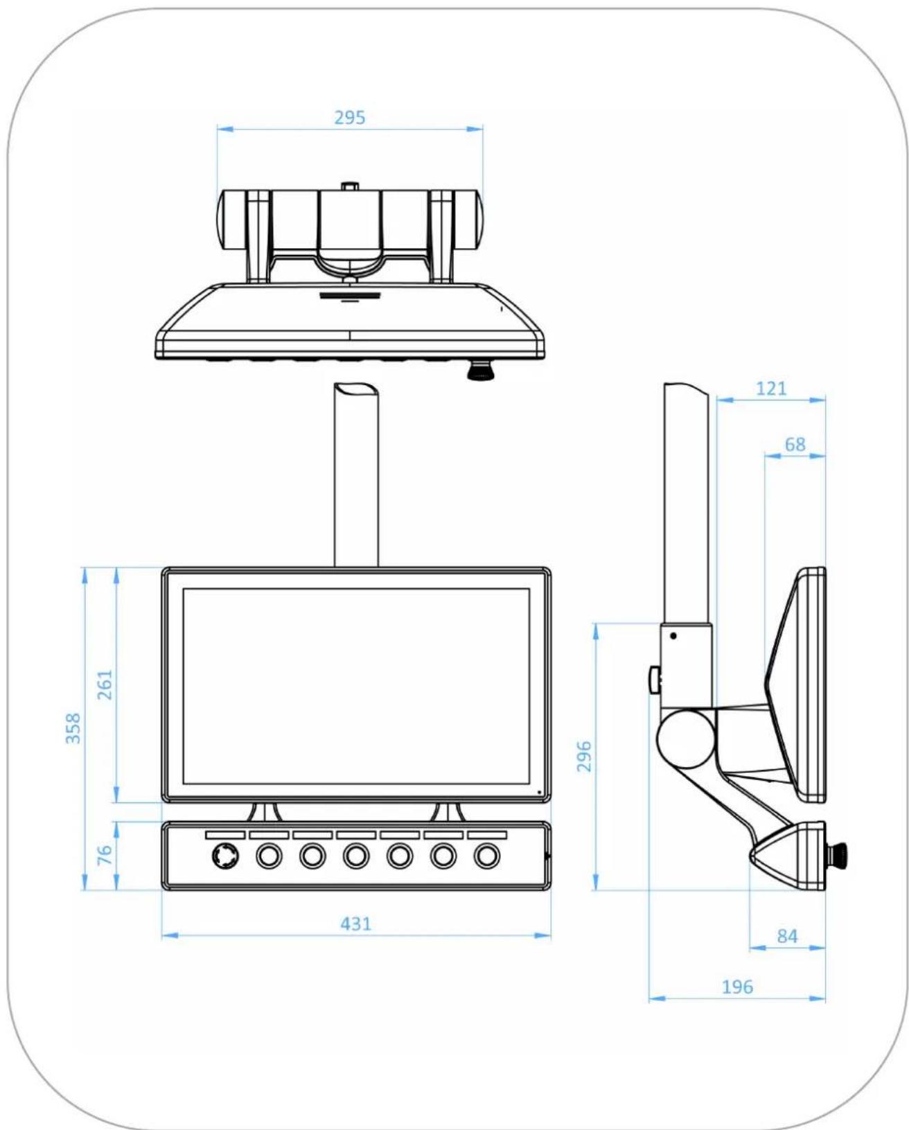
text_image
295 358 261 76 431 296 121 68 84 196Figure 63: External device dimensions MMD8017
11.1.5 External device dimensions MMD8024
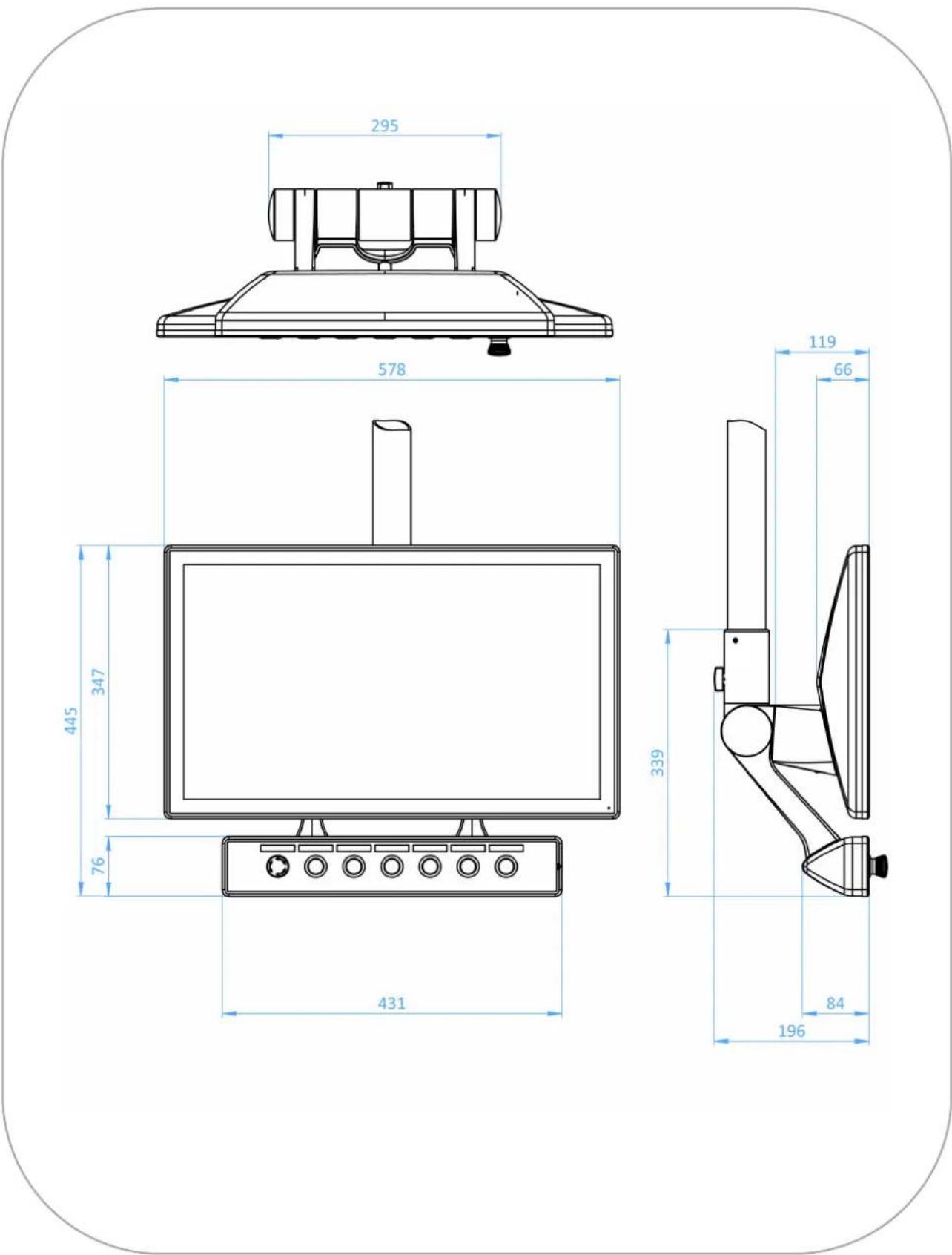
text_image
295 578 445 347 76 431 119 66 339 84 196Figure 64: External device dimensions MMD8024
11.2 HDBaseT™ Extender Kit technical data
11.2.1 Data sheet
Transmitter Tx Receiver Rx
| Housing | Aluminium die-casting housing | - |
| Interfaces | 1 x USB 2.0 | 1 x USB 2.0 |
| 1 x HDMI | 1 x HDMI | |
| 1 x HDBaseTTM 100Mbit | 1 x HDBaseTTM 100Mbit | |
| Power supply | 18 – 30 V--- NEC Class 2 | 18 – 30 V--- NEC Class 2 |
| Protection class | IP 20 IP 20 | |
| Operating temperature | 0° to 55°C 0° to 50°C | |
| Dimensions (W x H x D) | 140 x 159 x 35 mm 74 x 105 x 27 mm | |
| Weight | 0.7 kg | 0.2 Kg |
| Humidity | 10 to 85% non-condensing | |
11.2.2 External device dimensions – HDBaseT™ Extender Kit transmitter
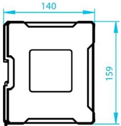
text_image
140 159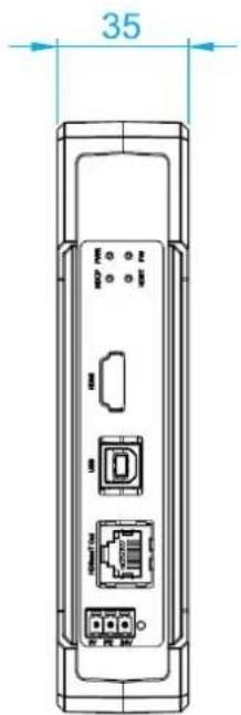
text_image
35Figure 65: External device dimensions – HDBaseT™ Extender Kit transmitter
11.2.3 External device dimensions – HDBaseT™ Extender Kit receiver
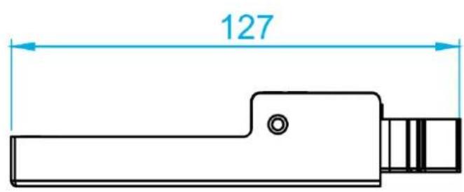
text_image
127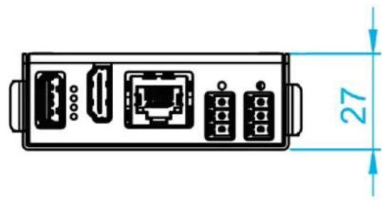
text_image
27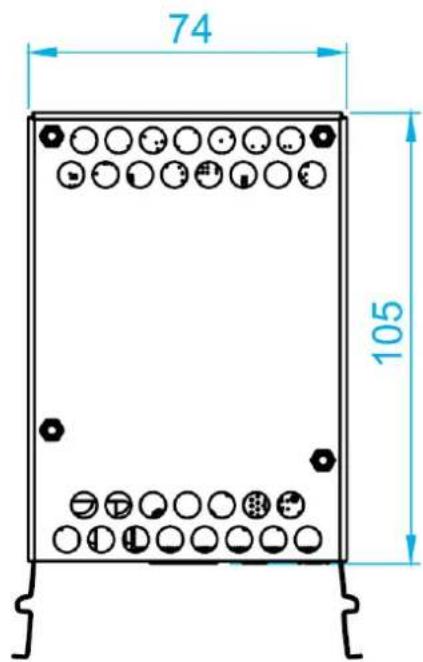
text_image
74 105Figure 66: External device dimensions – HDBaseT™ Extender Kit receiver
12 List of figures
Figure 1: Use of MMT and MMD 6
Figure 2: Mounting on support arm and stand 7
Figure 3: Crosspiece adapter .... 7
Figure 4: Turning and tilting....8
Figure 5: VESA adapter....8
Figure 6: Inclination angles at support arm adapter or crosspiece adapter 22
Figure 7: Overview of screw connection to support arm adapter....23
Figure 8: Overview of screw connection to VESA 75 adapter 23
Figure 9: Designations....24
Figure 10: Service slot – MMT 8000 series....25
Figure 11: Service slot – MMD8000 series ...... 26
Figure 12: Screw connection of adapter to device 28
Figure 13: Opening key module ...... 29
Figure 14: Prepunched openings in key module....30
Figure 15: Labelling strip 30
Figure 16: Inserting labelling strip .... 30
Figure 17: Cables of key module....31
Figure 18: Closing key module....31
Figure 19: Mounting on support arm and stand 32
Figure 20: Screws in support arm adapter and clamping block 32
Figure 21: Support arm and stand position 32
Figure 22: Inserting screws in adapter .... 33
Figure 23: Installation template .... 34
Figure 24: Countersinking connecting tube (support arm)....34
Figure 25: Installation template 35
Figure 26: Countersinking connecting tube (stand) 35
Figure 27: Cable routing for support arm mounting 36
Figure 28: Cable routing for stand mounting 36
Figure 29: Screwing adapter to tube (support arm) 37
Figure 30: Screwing adapter to tube (stand).... 37
Figure 31: USB flap .... 38
Figure 32: Removing service slot cover .... 38
Figure 33: USB cable on service slot cover 39
Figure 34: Retainer tabs of service slot cover 39
Figure 35: USB flap 39
Figure 36: Mounting device on adapter....40
Figure 37: Screwing device to adapter....40
Figure 38: Installation with crosspiece adapter .... 41
Figure 39: Crosspiece adapter ....41
Figure 40: Device with VESA adapter 42
Figure 41: Retainer plates on VESA adapter 42
Figure 42: Rubber insert of VESA adapter....43
Figure 43: MMT service slot 45
Figure 44: Strain relief fixtures on support arm adapter....45
Figure 45: MMD service slot....48
Figure 46: Strain relief fixtures on support arm adapter....48
Figure 47: MMT – Functional earthing in the service slot .... 51
Figure 48: MMD without HDBaseT Extender Kit – Functional earthing in the service slot .... 52
Figure 49: MMD with HDBaseT Extender Kit – Functional earthing in the service slot .... 52
Figure 50: Example: Earth connection of the optional key module.... 53
Figure 51: Use of HDBaseT™ Extender Kit....54
Figure 52: Receiver module in the service slot .... 54
Figure 53: Interfaces of receiver module....55
Figure 54: Interfaces of transmitter module....57
Figure 55: Status indicators on transmitter module.... 58
Figure 56: Status indicators on receiver module....59
Figure 57: Touch-screen 62
Figure 58: Tilting the device 63
Figure 59: Tilting the key module 64
Figure 60: Turning the device....64
Figure 61: External device dimensions MMT8017 76
Figure 62: External device dimensions MMT8024 77
Figure 63: External device dimensions MMD8017....78
Figure 64: External device dimensions MMD8024....79
Figure 65: External device dimensions – HDBaseT™ Extender Kit transmitter .... 81
Figure 66: External device dimensions – HDBaseT™ Extender Kit receiver ....82
13 Service & support
ADS-TEC and its partner companies offer you comprehensive maintenance and support services, ensuring quick and competent support should you have any questions or concerns with regard to ADS-TEC products and equipment.
Because ADS-TEC products are also used by partner companies, these devices may have customised configurations. Should any questions arise with regard to such specific configurations and software installations, please contact the system supplier in question as ads-tec will not be able to answer such questions.
ADS-TEC does not provide support services for any device that was not purchased directly from ADS-TEC. In this case, maintenance and support is provided by the partner company.
13.1 ADS-TEC support
The ADS-TEC support team is available for inquiries from direct customers between 8:30am and 5:00pm, Monday to Friday
and can be reached via phone, fax or e-mail:
Phone: +49 7022 2522-202
Email: support@ads-tec.de
Alternatively, you can contact us by completing a support form on our website www.ads-tec.de. Our Support team will then get in touch with you as soon as possible.