
IUPS-NET504 - Network card / adapter Techly - Free user manual and instructions
Find the device manual for free IUPS-NET504 Techly in PDF.


| Product Type | Network card / adapter (SNMP card for UPS monitoring) |
| Brand | Techly |
| Model | IUPS-NET504 |
| Interface | RJ45 (Ethernet), RS232, USB (model dependent) |
| Ethernet Speed | 10/100 Mbps auto-sensing |
| Supported Protocols | TCP/IP, UDP, SNMP, Telnet, HTTP, HTTPS, SSH, SMTP, Modbus |
| Management | Web browser, Telnet, NMS (e.g., SNMPView) |
| Security | SSL/TLS, SSH encryption |
| LED Indicators | Power, Communication status, Ethernet link/activity |
| Power Supply | 5.3V DC via external adaptor |
| Operating Temperature | 0°C to 40°C (32°F to 104°F) |
| Operating Humidity | 20% to 80% RH non-condensing |
| Dimensions | Approx. 100 x 60 x 25 mm (3.9 x 2.4 x 1.0 in) |
| Weight | Approx. 100 g (3.5 oz) |
| Compatibility | UPS with Contact Closure or RS232 interface |
| Monitoring Features | SNMP MIB, remote UPS monitoring, shutdown control |
| Notification Methods | SNMP trap, email, SMS (with optional modem) |
| Included Software | Netility (configuration), ClientMate (shutdown), SNMPView (NMS), etc. |
| Optional Sensors | NetFeeler II for temperature, humidity, water, smoke, etc. |
| Package Contents | NetAgent card, utility CD, quick installation guide, cables, adaptor (model dependent) |
Frequently Asked Questions - IUPS-NET504 Techly
User questions about IUPS-NET504 Techly
0 question about this device. Answer the ones you know or ask your own.
Ask a new question about this device
Download the instructions for your Network card / adapter in PDF format for free! Find your manual IUPS-NET504 - Techly and take your electronic device back in hand. On this page are published all the documents necessary for the use of your device. IUPS-NET504 by Techly.
USER MANUAL IUPS-NET504 Techly
Copyright © 2000-2017, Mega System Technologies, Inc.
All rights reserved.
Reproduction without permission is prohibited.
Technical Support and Contact Information
Mega System Technologies, Inc.
Chapter 1. Introduction...... 1
1.1 Features .... 1
1.2 Applications....2
Chapter 2. NetAgent Series .... 4
2.1 NetAgent Mini 4
2.1.1 NetAgent Mini Outlook....5
2.1.2 NetAgent Mini LED Indication 6
2.2 NetAgent II Models....7
2.2.1 NetAgent II Outlook ....7
2.2.2 NetAgent II Led Indication.... 10
2.3 NetAgent Mini 9/ NetAgent 9....11
2.3.1 NetAgent Mini 9 Outlook 12
2.3.2 NetAgent Mini 9 LED Indication 14
2.4 NetAgent 9 Series....16
2.4.1 NetAgent 9 Outlook 16
2.4.2 NetAgent 9 LED Indication.... 20
2.5 NetAgent Mini 9 / NetAgent 9 Package Accessories 21
Chapter 3. NetAgent Installation ...... 22
3.1 Hardware Installation 22
Internal NetAgent 22
External NetAgent Mini....23
External NetAgent II / 9....24
3.2 Software Installation 25
Chapter 4. NetAgent Setting ...... 26
4.1 Introduction 26
4.2 NetAgent Login Procedure.... 27
4.3 Netility Installation and Setting 29
4.4 NetAgent Setting 38
4.4.1 Web Interface.... 38
4.4.2 NetAgent Option Directory Structure 40
4.4.3 NetAgent Setting Options 41
Information > System Status 41
Information > Basic Information.... 43
Information > Current Status 44
Information > Remote Control 45
Information > Meter/Chart 46
Information > SMS Modem Status.... 48
Information > NetSwitch Status.... 49
Information > NetFeeler (NetFeeler II).... 50
Configuration > UPS Configuration .... 51
Configuration > UPS On/Off Schedule 54
Configuration > Network 58
Configuration > Wireless 66
Configuration > SNMP 68
Configuration > Email....75
Configuration > SMS 80
Configuration > Web/Telnet 83
Configuration > System Time 88
Configuration > SMS Modem....90
Configuration > NetSwitch 95
Configuration > NetFeeler 100
Configuration > MODBUS 103
Configuration > Language 106
Log Information > Event Log 107
Log Information > SMS Log 108
Log Information > Data Log 109
Log Information > Battery Test Log 111
Help > Search NetAgent ....113
Help > Serial Port Debug....114
Help > Help ....116
Help > About....117
Chapter 5. Telnet/ SSH ....120
Chapter 6. ClientMate....122
Chapter 7. SNMP View....130
Chapter 8. iMConfig....138
Chapter 9. SMS Server Software ....142
Chapter 10. Appendix....148
Chapter 1. Introduction
1.1 Features
NetAgent is the SNMP (Simple Network Management Protocol) card for monitoring UPS. Not only could remote control the UPS and get the current status of it, the NetAgent that has 3 ports or USB ports could also provide other functions, ex. connect to compatible modem to send SMS notification, or our NetFeeler II and its additional sensors for ambient temperature, humidity and water status. This product is for “Contact Closure” and “RS232” interface UPS. The communication protocol includes the Contact Closure, RS232[MegaTec], Phoenixtec], SEC 2400, SEC 9600, Megatec Three Phase, ..etc. NetAgent provides a simple and easy installation procedure. CD provides along with NetAgent offers several software to allow the user to configure IP address; central monitoring and multi shutdown on different operating systems. Other advance configurations could be accomplished in the Web browser.
Features:
① Provide SNMP MIB to monitor & control UPS
② Auto-sense 10M /100M Fast Ethernet (10M/100M/1000M is available for specific model)
③ Manage and configure via Telnet, Web Browser or NMS
4 Support TCP/IP, UDP, SNMP, Telnet, SNTP, PPP, HTTP, HTTPS, SMTP, Modbus Protocol
⑤ Support SSL/TLS, SSH Encryption
⑥ Providing easy setup and upgrade tools via our Netility software
⑦ Send SNMP TRAP ; E-mail and SMS for events notification.
8 Auto email daily UPS history report
⑨ Perform graceful shutdown with our ClientMate software
10 Add-on optional NetFeeler II for temperature, humidity, water, smoke and door sensor
1.2 Applications
■ NetAgent allows UPS to be monitor on network
When the UPS connects with NetAgent, the system manager could check each and every UPS condition by a computer with Browser installed. The manager could monitor and control the UPS by simply input the IP address of the NetAgent which connects to the UPS. When there is a power abnormal condition happens, the NetAgent could also send the trap information to the system manager to take proper action.
■ NetAgent Provides Shutdown Utilities
When a computer install our shutdown software in the network that connects to the NetAgent, when UPS is in AC failure condition or Battery Low condition, the software would close all the files of the operating system and shutdown gracefully. This could avoid system corrupt when a power disconnection happened.
■ NetAgent II for Surrounding Monitoring
3 Ports NetAgent or NetAgent with USB ports could connect to optional sensor-NetFeeler II to get the surrounding temperature/humidity/smoke/fire signals. These information could also be revealed on the NetAgent Web page. When there is an abnormal condition happened, it could also be sent as a trap to the system manager.
When we need the NetAgent?
When we need to remote monitoring and controls the UPS conditions. For example, the system manager could use the Internet to control all the UPS conditions all over the country. When the shutdown utility is installed, the shutdown utility could close all the files and shutdown the system when a power abnormal condition happened.
② When we need to monitor surrounding conditions of the server room, warehouse, office, etc. For example, the system manager could know the temperature, humidity, smoke and water condition by our NetFeeler II which connects with NetAgent. User may read the data via NetAgent webpage.
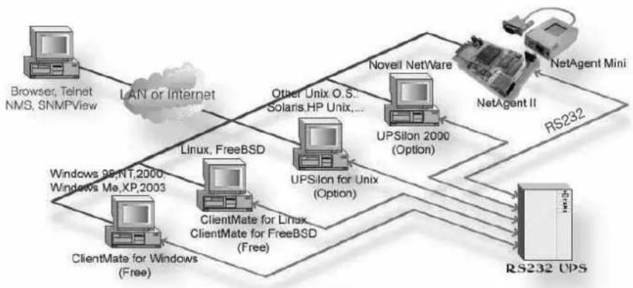
flowchart
graph TD
    A["Browser, Telnet NMS, SNMPView"] -->|LAN or Internet| B["ClientMate for Windows (Free)"]
    A --> C["ClientMate for Linux ClientMate for FreeBSD (Free)"]
    C --> D["ClientMate for Windows 98,NT,2000, Windows Me,XP,2003"]
    C --> E["ClientMate for Linux ClientMate for FreeBSD (Option)"]
    C --> F["UPSilon for Unix (Option)"]
    F --> G["UPSilon 2000 (Option)"]
    G --> H["Novell NetWare"]
    H --> I["NetAgent II"]
    I --> J["NetAgent Mini"]
    J --> K["RS232 UPS"]
    G --> L["RS232"]
    style A fill:#f9f,stroke:#333
    style K fill:#ccf,stroke:#333
Fig.1 Network connection diagram of NetAgent and shutdown software
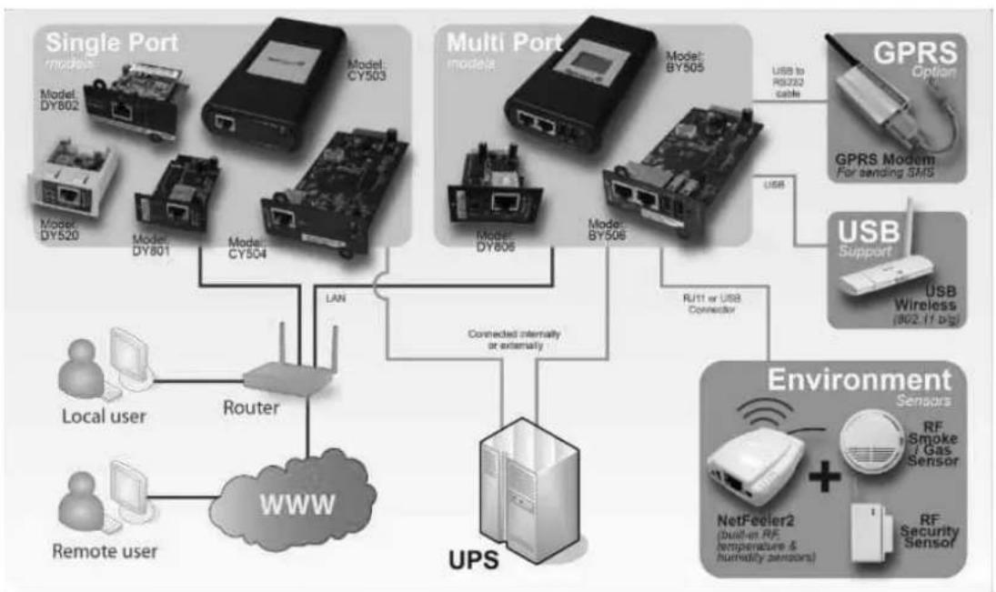
flowchart
graph TD
    A["Single Port"] -->|LAN| B["Router"]
    C["Multi Port"] -->|USB to RS202 cable| D["GPRS Option"]
    D --> E["USB Support"]
    F["Environment Sensors"] --> G["NetFecler2 (built-in RF, temperature & humidity sensors)"]
    G --> H["RF Security Sensor"]
    I["Local user"] --> B
    J["Remote user"] --> B
    B --> K["WWW"]
    L["UPS"] --> M["Connected internally or externally"]
    M --> N["Model: BY506"]
    M --> O["Model: BY505"]
    P["Local user"] --> B
    Q["Remote user"] --> B
    R["Multi Port"] --> S["Model: CY504"]
    S --> T["Model: CY503"]
    U["Multi Port"] --> V["Model: DY806"]
    V --> W["Model: DY801"]
    X["Environment Sensors"] --> Y["RF Smoke / Gas Sensor"]
    Z["Local user"] --> B
    AA["Remote user"] --> B
Fig.2 NetAgent 9 connection diagram with NetFeeler
Chapter 2. NetAgent Series
2.1 NetAgent Mini
| NetAgent Mini Model | |||||||||
| Model Name | Package Contents | Internal | External | RJ45 Port | RS232 Port | ENV Port | USB Port | Single Phase | Three Phase |
| DP520DT520 | 1. NetAgent Mini SNMP Card2. NetAgent Utility CD3. Quick Installation Guide (Optional) | V | V | V | V | ||||
| DP801DT801 | 1. NetAgent Mini SNMP Card2. NetAgent Utility CD3. Quick Installation Guide (Optional) | V | V | V | V | ||||
| DP802DT802 | 1. NetAgent Mini SNMP Card2. NetAgent Utility CD3. Quick Installation Guide (Optional) | V | V | V | V | ||||
| DP522DT522 | 1. NetAgent Mini SNMP Card2. NetAgent Utility CD3. Quick Installation Guide (Optional)4. Adaptor | V | V | V | V | ||||
| DP523DT523(Dry Contact Only) | 1. NetAgent Mini SNMP Card2. NetAgent Utility CD3. Quick Installation Guide (Optional)4. Adaptor | V | V | V | V | ||||
| DP532DT532 | 1. NetAgent Mini SNMP Card2. NetAgent Utility CD3. Quick Installation Guide (Optional)4. Adaptor | V | V | V | V | ||||
| DP630 | 1. USB NetAgent Mini SNMP Card2. NetAgent Utility CD3. Quick Installation Guide (Optional)4. Adaptor | V | V | V | V | ||||
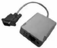
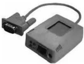
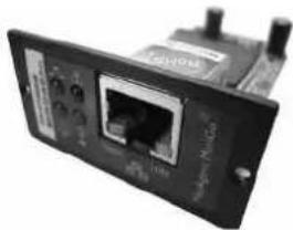
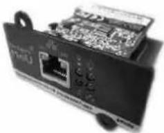
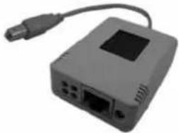
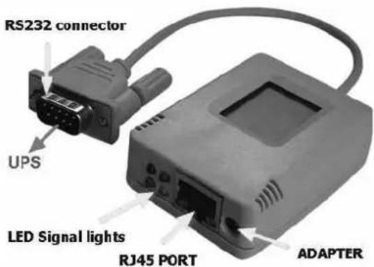
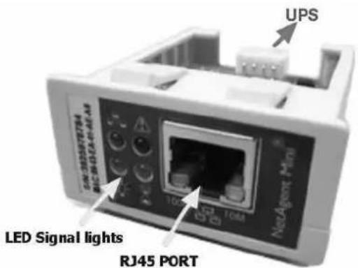
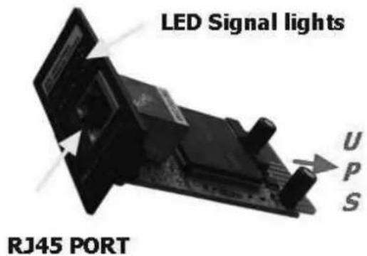
2.1.1 NetAgent Mini Outlook
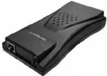
| DP/DT520 | DP/DT522 | DP/DT523 | DP/DT532 |
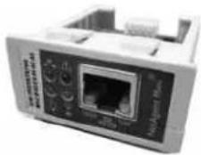 | 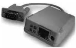 |  |  |
| DP/DT801 | DP/DT802 | DP630 | |
 |  |  |
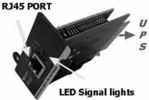
2.1.2 NetAgent Mini LED Indication
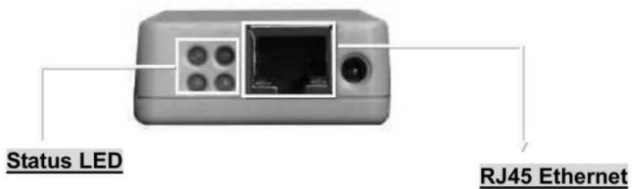
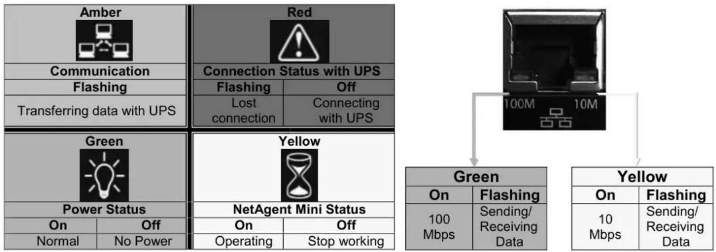
flowchart
graph TD
    A["Amber"] --> B["Communication"]
    A --> C["Flashing"]
    A --> D["Transferring data with UPS"]
    E["Red"] --> F["Connection Status with UPS"]
    E --> G["Flashing"]
    E --> H["Off"]
    E --> I["Lost connection"]
    E --> J["Connecting with UPS"]
    K["Green"] --> L["Power Status"]
    K --> M["NetAgent Mini Status"]
    K --> N["On"]
    K --> O["Off"]
    K --> P["Normal"]
    K --> Q["No Power"]
    R["Yellow"] --> S["Green"]
    R --> T["Yellow"]
    U["100M"] --> V["Green"]
    W["10Mbps"] --> X["Green"]
    Y["10Mbps"] --> Z["Yellow"]
    AA["10Mbps"] --> AB["Yellow"]
    AC["10Mbps"] --> AD["Yellow"]
NOTE : When writing firmware, red and yellow led alternating flashing, DO NOT remove any power
2.2 NetAgent II Models
| NetAgent II Model | |||||||||
| Model Name | Package Content | Internal | External | RJ45 | RS232 | ENV | USB | Single Phase | Three Phase |
| CP503CT503 | 1. NetAgent SNMP Card2. NetAgent Utility CD3. Quick Installation Guide (Optional)4. M2501 Cable( For Dry Contact UPS)5. M2502 or M2505 Cable(For RS232 UPS)6. Adaptor | V | V | V | V | ||||
| CP504CT504 | 1. NetAgent SNMP Card2. NetAgent Utility CD3. Quick Installation Guide (Optional) | V | V | V | V | ||||
| BT505 | 1. NetAgent SNMP Card2. NetAgent Utility CD3. Quick Installation Guide (Optional)4. M2501 Cable( For Dry Contact UPS)5. M2502 or M2505 Cable(For RS232 UPS)6. M2506 Cable (For Modem)7. Adaptor | V | V | V | V | V | V | ||
| BT506 | 1. NetAgent SNMP Card2. NetAgent utility CD3. Quick Installation Guide (Optional)4. M2506 Cable (For Modem)5. Adaptor | V | V | V | V | V | V | ||
NOTE : Model CP/CT are discontinued.
2.2.1 NetAgent II Outlook
| CP/CT 503 | CP/CT 504 |
 | 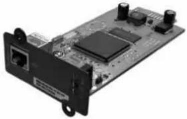 |
| BT505 | BT506 |
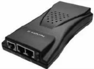 | 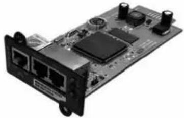 |
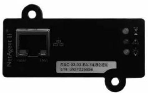
One Port NetAgent II
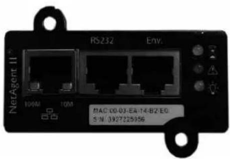
◆ Three Ports NetAgent II
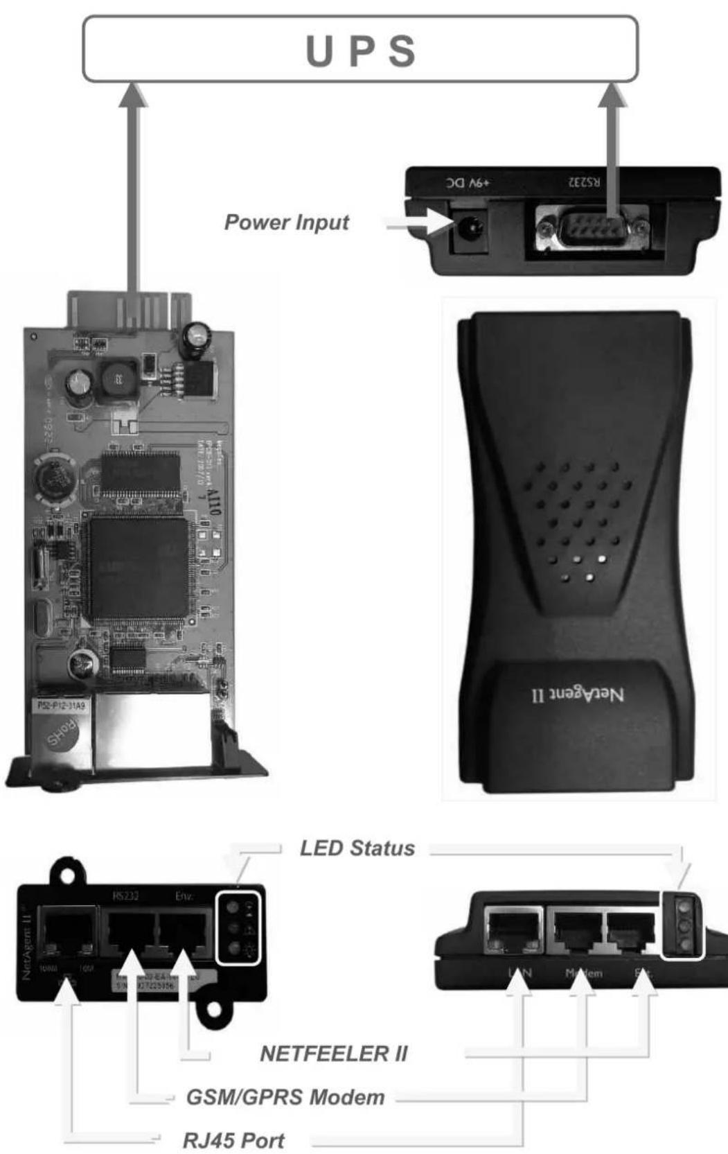
2.2.2 NetAgent II Led Indication
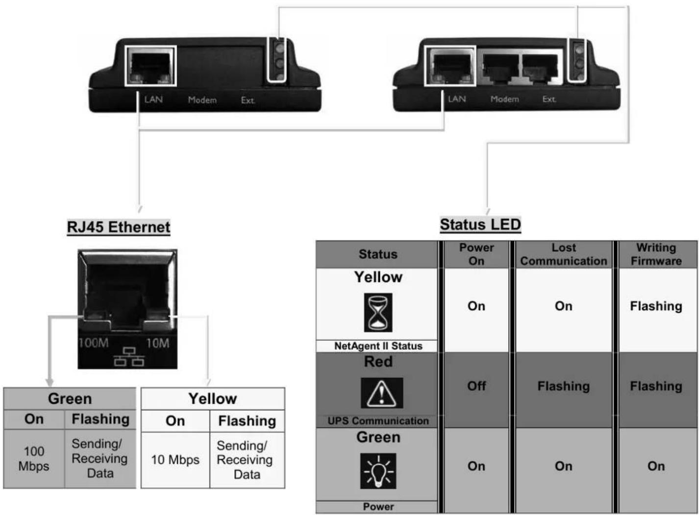
flowchart
graph TD
    A["RJ45 Ethernet"] --> B["Green"]
    A --> C["Yellow"]
    B --> D["On"]
    B --> E["Flashing"]
    C --> F["On"]
    C --> G["Flashing"]
    H["Status LED"] --> I["Red UPS Communication"]
    I --> J["Green Power"]
    I --> K["Off"]
    I --> L["Power On"]
    M["Status LED"] --> N["Power On"]
    M --> O["Lost Communication"]
    M --> P["Writing Firmware"]
    style M fill:#f9f,stroke:#333
NOTE : When writing firmware, red and yellow led alternating flashing, DO NOT remove any power
2.3 NetAgent Mini 9/ NetAgent 9
NetAgent Mini 9 Models
| NetAgent Mini 9 Model | |||||||||
| Model Name | Package Contents | Internal | External | RJ45 | RS232 | ENV | USB | Single Phase | Three Phase |
| DX520DY520 | 1. NetAgent Mini 9 SNMP Card2. NetAgent Utility CD3. Quick Installation Guide (Optional) | V | V | V | V | ||||
| DX801DY801 | 1. NetAgent Mini 9 SNMP Card2. NetAgent Utility CD3. Quick Installation Guide (Optional) | V | V | V | V | ||||
| DX802DY802 | 1. NetAgent Mini 9 SNMP Card2. NetAgent Utility CD3. Quick Installation Guide (Optional) | V | V | V | V | ||||
| DX806DY806 | 1. NetAgent Mini 9 SNMP Card2. NetAgent Utility CD3. Quick Installation Guide (Optional)4. M2509 Cable (USB) | V | V | V | V | V | |||
| DY807 | 1. NetAgent Mini 9 SNMP Card2. NetAgent Utility CD3. Quick Installation Guide (Optional) | V | V | V | V | V | |||
| DX522DY522 | 1. NetAgent Mini 9 SNMP Card2. NetAgent Utility CD3. Quick Installation Guide (Optional)4. Adaptor | V | V | V | V | ||||
| DX523DY523(Dry Contact Only) | 1. NetAgent Mini 9 SNMP Card2. NetAgent Utility CD3. Quick Installation Guide (Optional)4. Adaptor | V | V | V | V | ||||
| DX532DY532 | 1. NetAgent Mini 9 SNMP Card2. NetAgent Utility CD3. Quick Installation Guide (Optional)4. Adaptor | V | V | V | V | ||||
| DX630DY630 | 1. USB NetAgent Mini 9 SNMP Card2. NetAgent Utility CD3. Quick Installation Guide (Optional)4. Adaptor | V | V | V | V | ||||
2.3.1 NetAgent Mini 9 Outlook
| NetAgent Mini 9 Series | |||
| DX/DY 520 | DX/DY 522 | DX/DY 523 | DX/DY 532 |
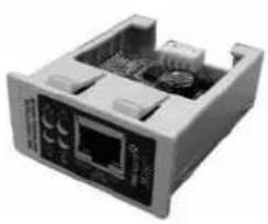 | 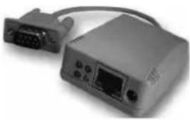 | 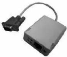 | 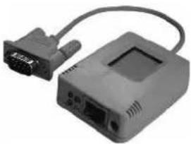 |
| DX/DY 801 | DX/DY 802 | DX/DY 806 | DY 807 |
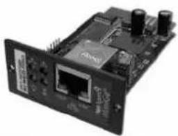 | 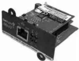 | 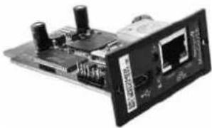 | 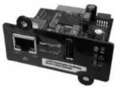 |
| DX/DY 630 | |||
 | |||
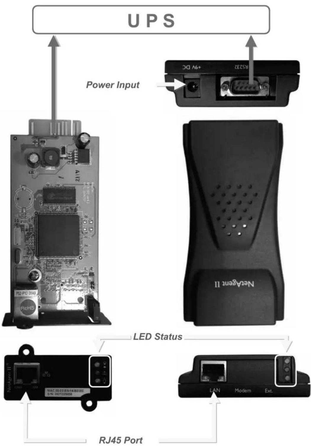
DX/DY Internal
LED Status

RJ45 Port
DX/DY External
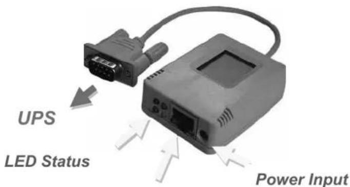
RJ45 Port

2.3.2 NetAgent Mini 9 LED Indication
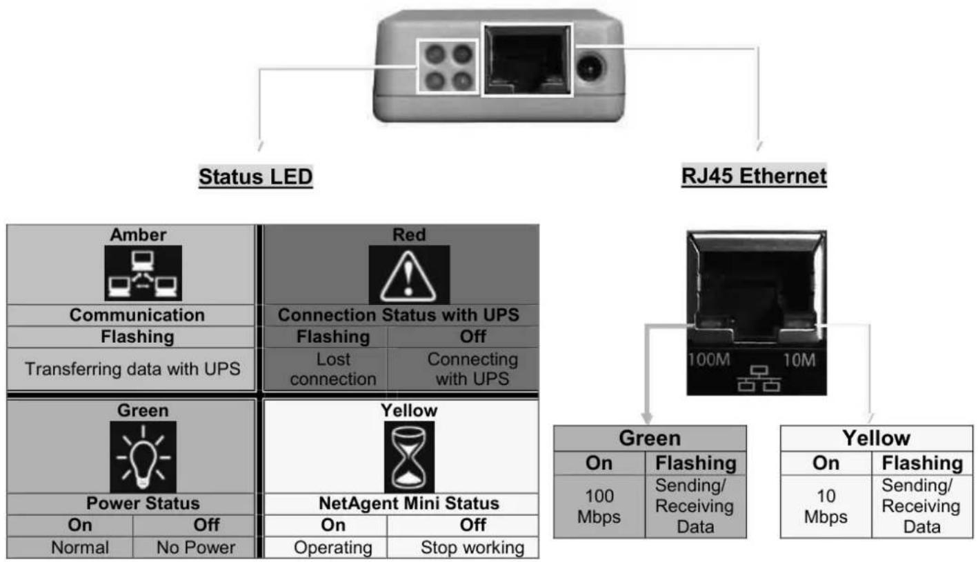
flowchart
graph TD
    A["User"] --> B["Status LED"]
    A --> C["RJ45 Ethernet"]
    B --> D["Amber"]
    B --> E["Red"]
    D --> F["Communication"]
    D --> G["Flashing"]
    D --> H["Transferring data with UPS"]
    E --> I["Connection Status with UPS"]
    E --> J["Flashing"]
    E --> K["Off"]
    E --> L["Lost connection"]
    E --> M["Connecting with UPS"]
    N["Green"] --> O["Power Status"]
    N --> P["Yellow"]
    O --> Q["On"]
    O --> R["Off"]
    O --> S["Normal"]
    O --> T["No Power"]
    U["NetAgent Mini Status"] --> V["On"]
    U --> W["Off"]
    U --> X["Operating"]
    U --> Y["Stop working"]
    Z["Green"] --> AA["On"]
    Z --> AB["Flashing"]
    Z --> AC["100 Mbps"]
    Z --> AD["Sending/Receiving Data"]
    AE["Yellow"] --> AF["On"]
    AE --> AG["Flashing"]
    AE --> AH["10 Mbps"]
    AE --> AI["Sending/Receiving Data"]
NOTE : When writing firmware, red led alternating flashing, DO NOT remove any power
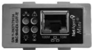
DX/DY 520 Internal
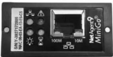
DX/DY 801
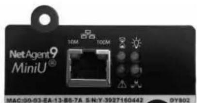
DX/DY 802
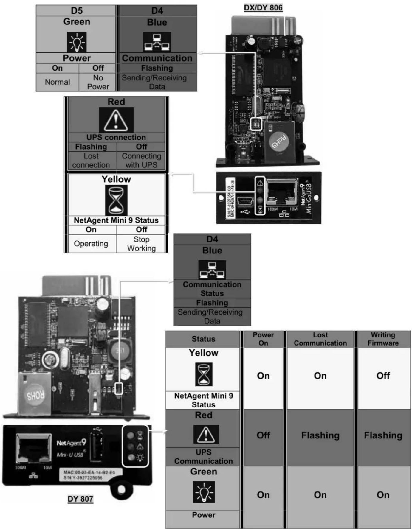
flowchart
graph TD
    subgraph Power
        A["D5 Green"] --> B["Power"]
        C["Off Normal"] --> D["No Power"]
    end

    subgraph UPS connection
        E["Red"] --> F["Flashing"]
        F --> G["Lost connection"]
        H["Off Connecting with UPS"]
    end

    subgraph Yellow
        I["Yellow"] --> J["NetAgent Mini 9 Status"]
        K["On Operating"] --> L["Stop Working"]
    end

    subgraph DY 807
        M["D4 Blue"] --> N["Communication Status"]
        O["Off Flashing"] --> P["Sending/Receiving Data"]
    end

    style Power fill:#f9f,stroke:#333
    style UPS connection fill:#ccf,stroke:#333
    style Yellow fill:#cfc,stroke:#333
    style DY 807 fill:#fcc,stroke:#333

    %% Note: The diagram shows connections between components (D5-D4, D4-DX/DY-806) and associated status indicators (Status, Power, Status).
2.4 NetAgent 9 Series
| NetAgent 9 Model | |||||||||
| Model Name | Package Contents | Internal | External | RJ45 | RS232 | ENV | USB | Single Phase | Three Phase |
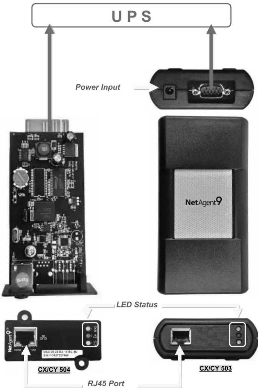
| CX/CY 503 | 1. NetAgent 9 SNMP Card2. NetAgent Utility CD3. Quick Installation Guide (Optional)4. M2501 Cable(For Dry Contact UPS)5. M2502or M2505 Cable(For RS232 UPS)6. Adaptor | V | V | V | V | ||||
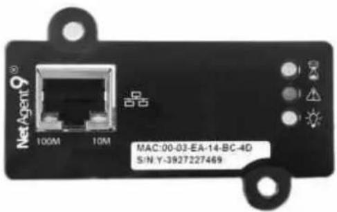
| CX/CY 504 | 1. NetAgent 9 SNMP Card2. NetAgent Utility CD3. Quick Installation Guide (Optional) | V | V | V | V | ||||
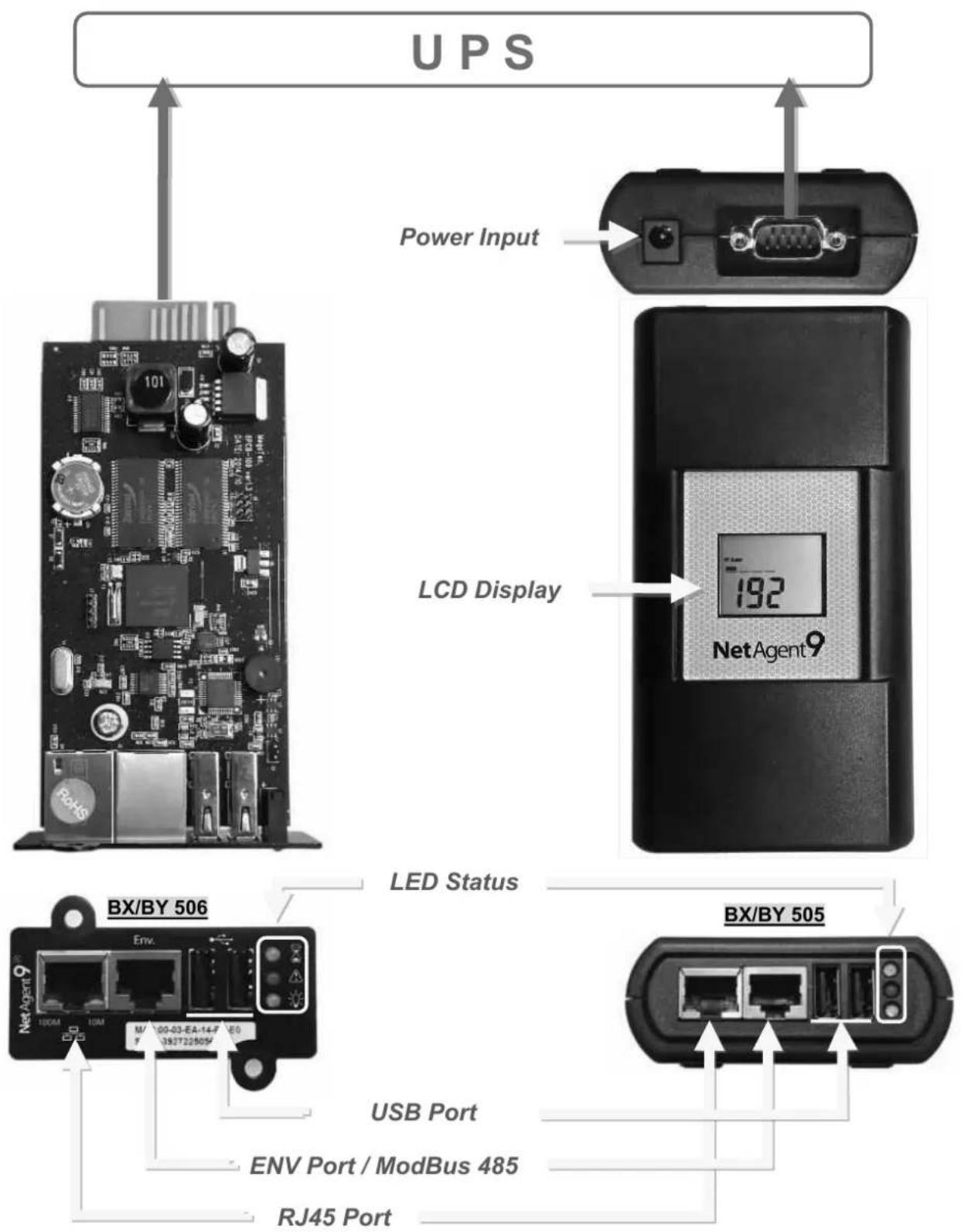
| BX/BY 505 | 1. NetAgent 9 SNMP Card2. NetAgent Utility CD3. Quick Installation Guide (Optional)4. M2501 Cable(For Dry Contact UPS)5. M2502 or M2505 Cable(For RS232 UPS)6. M2506 Cable ( For ModBus on RS485)7. RS485 Converter board8. Adaptor | V | V | V | V | V | V | ||
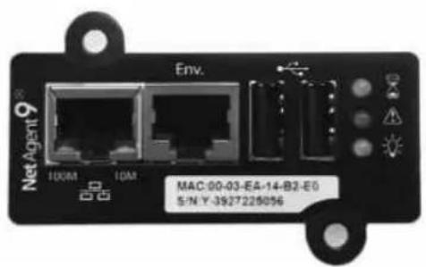
| BX/BY 506 | 1. NetAgent 9 SNMP Card2. NetAgent Utility CD3. Quick Installation Guide (Optional)4. M2506 Cable ( For ModBus on RS485)5. RS485 Converter board | V | V | V | V | V | V | ||
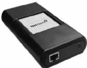
natural_image
Black electronic device with network port and a white label (no readable text or symbols beyond branding)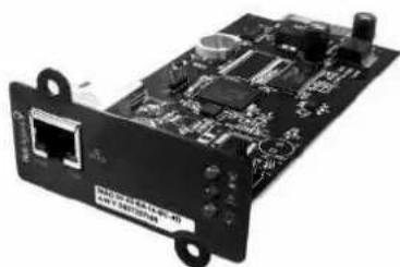
natural_image
Black electronic circuit board with ports and components (no visible text or symbols)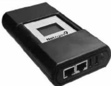
natural_image
Black wireless router device with network ports and a central display (no visible text or symbols)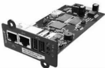
natural_image
Electronic circuit board with network ports and components (no visible text or symbols)One Port NetAgent 9
◆ NetAgent 9 W/USB Ports
◆ NetAgent 9 USB Port Add-On
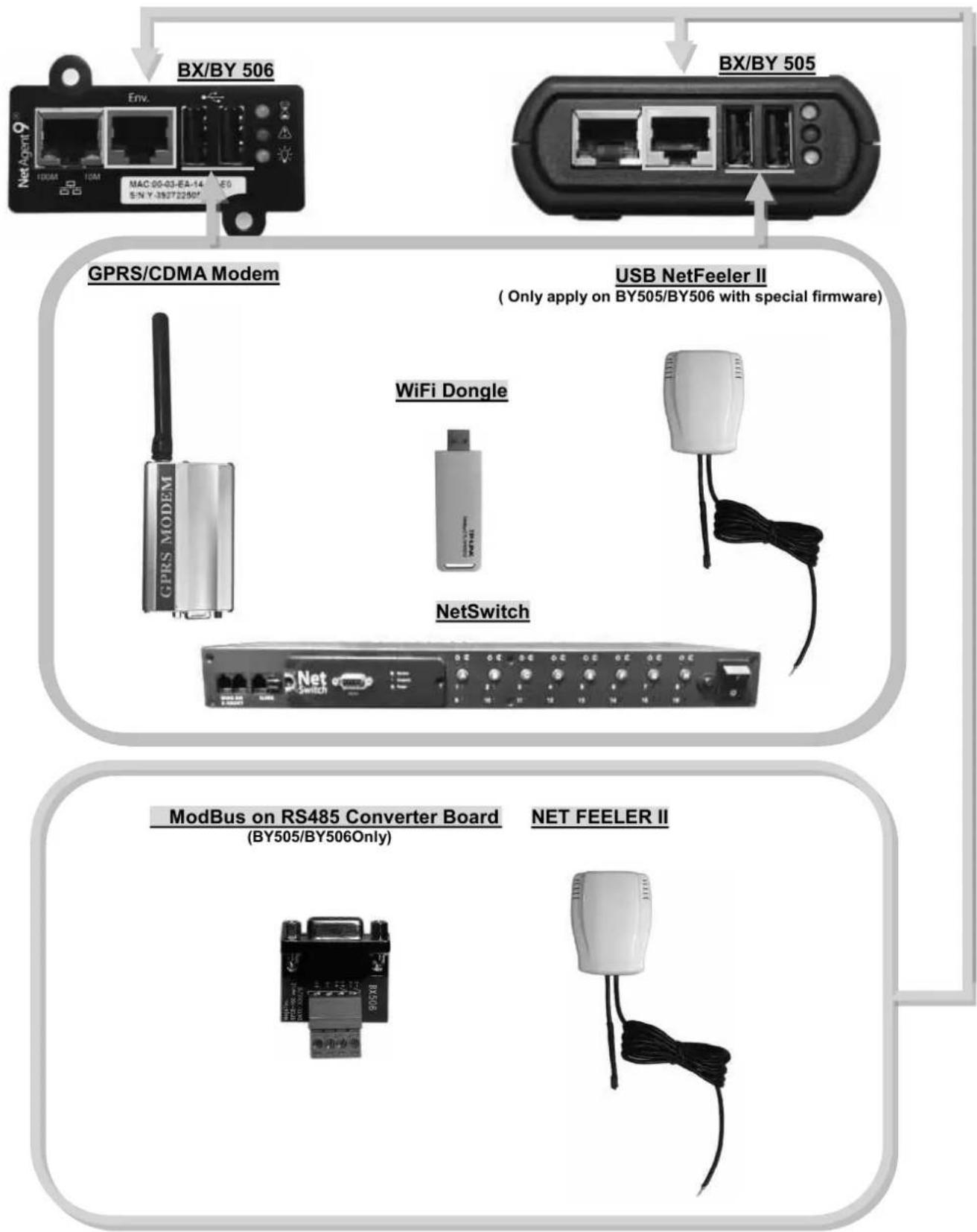
flowchart
graph TD
    A["Net Agent 9"] -->|BX/BY 506| B["GPRS/CDMA Modem"]
    C["Net Agent 9"] -->|BX/BY 505| D["USB NetFeeler II (Only apply on BY505/BY506 with special firmware)"]
    B --> E["WiFi Dongle"]
    B --> F["NetSwitch"]
    B --> G["ModBus on RS485 Converter Board (BY505/BY506Only)"]
    D --> H["Net Feeler II"]
    style A fill:#f9f,stroke:#333
    style C fill:#f9f,stroke:#333
    style B fill:#ccf,stroke:#333
    style D fill:#ccf,stroke:#333
    style E fill:#cfc,stroke:#333
    style F fill:#cfc,stroke:#333
    style G fill:#fcc,stroke:#333
2.4.2 NetAgent 9 LED Indication
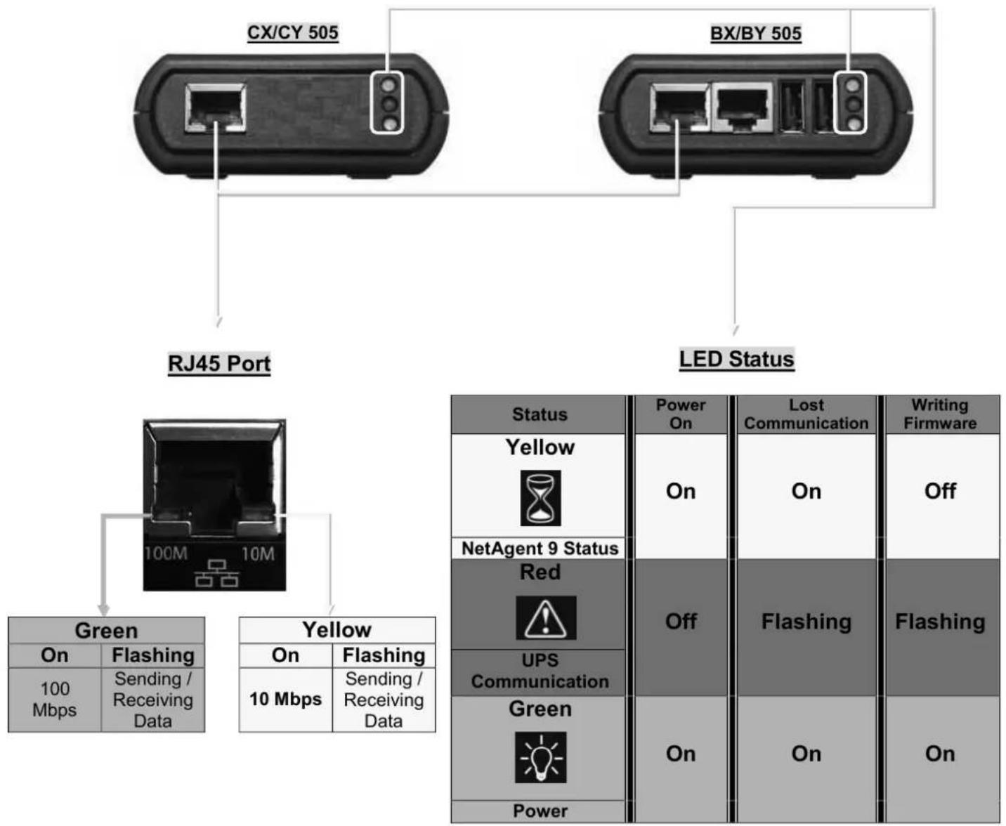
| Status | Power On | Lost Communication | Writing Firmware |
Yellow | On | On | Off |
| NetAgent 9 Status | |||
Red | Off | Flashing | Flashing |
| UPS Communication | |||
Green | On | On | On |
| Power |
NOTE : When writing firmware, red led alternating flashing, DO NOT remove any power
CX/CY 504
BX/BY 506
2.5 NetAgent Mini 9 / NetAgent 9 Package Accessories
(1) Utility CD
CD Contens :
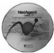
■ Netility - NetAgent Software too – IP configuration / Firmware Upgrade
■ ClientMate - Shutdown Software
■ SMS Server - SMS Notification Software (with compatible Modem)
■ SNMPView - NMS Software/ Multi Monitoring
■ Time Server - Time ServerSoftware
■ iMConfig - Multi Configuration Software
(2) Quick Installation Guide (Optional)
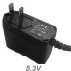
(3) Adaptor
natural_image
Black electrical plug with two leads and a 5.3V label, no readable text or symbols beyond the label.For NetAgent Mini Series
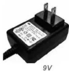
For NetAgent 9 Series
(4) ModBus On RS485
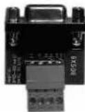
Coverter Board
(5) Cables
■ M2501 – For connection between NetAgent and dry contact UPS

natural_image
Pure electrical connector diagram showing two connected components (no text or symbols)■ M2502 – For connection between NetAgent and RS232 pin 6,7,9 UPS

natural_image
Pure electrical connector diagram showing two connected components (no text or symbols)■ M2505 –For connection between NetAgent and RS232 pin 2,3,5 UPS

natural_image
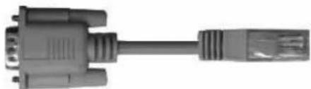
Pure electrical connector diagram showing two connected dials (no text or symbols)■ M2506 – For connection between NetAgent and GPRS / CDMA modem
natural_image
Close-up of a black VGA connector with metallic leads (no text or symbols visible)Chapter 3. NetAgent Installation
3.1 Hardware Installation
■ Internal NetAgent
NOTE : Turn Off UPS Power before installation
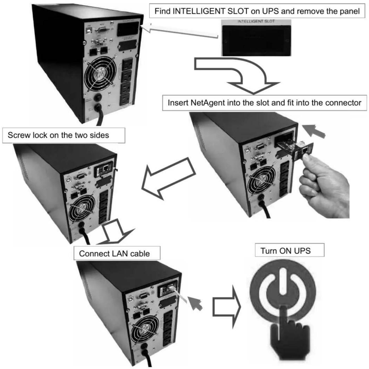
flowchart
graph TD
    A["Server with Inelligent Slot"] --> B["Find Intelligent Slot on UPS and remove the panel"]
    B --> C["Insert NetAgent into the slot and fit into the connector"]
    C --> D["Screw lock on the two sides"]
    D --> E["Connect LAN cable"]
    E --> F["Turn ON UPS"]
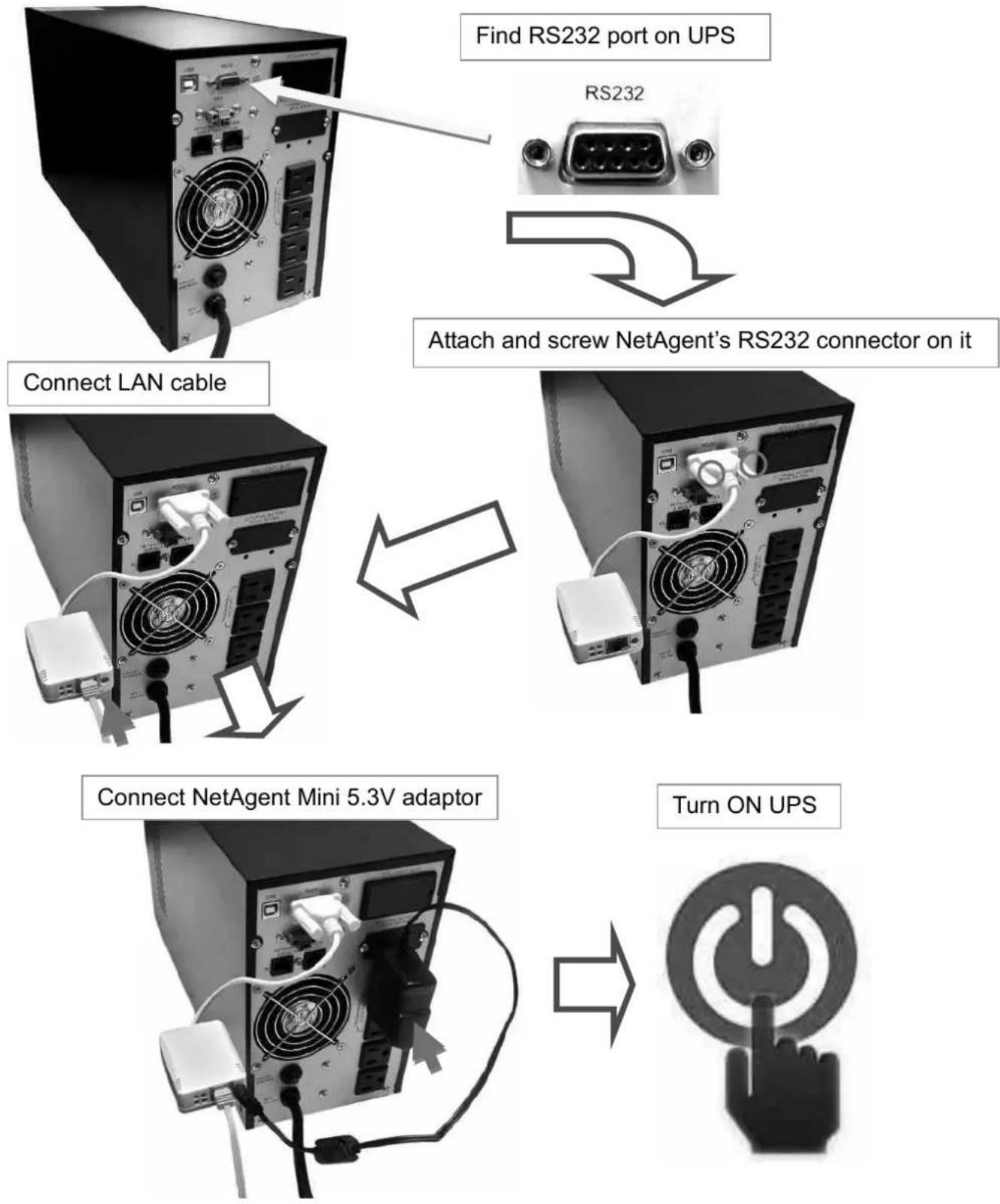
■ External NetAgent Mini
Turn Off UPS Power before installation
■ External NetAgent II / 9
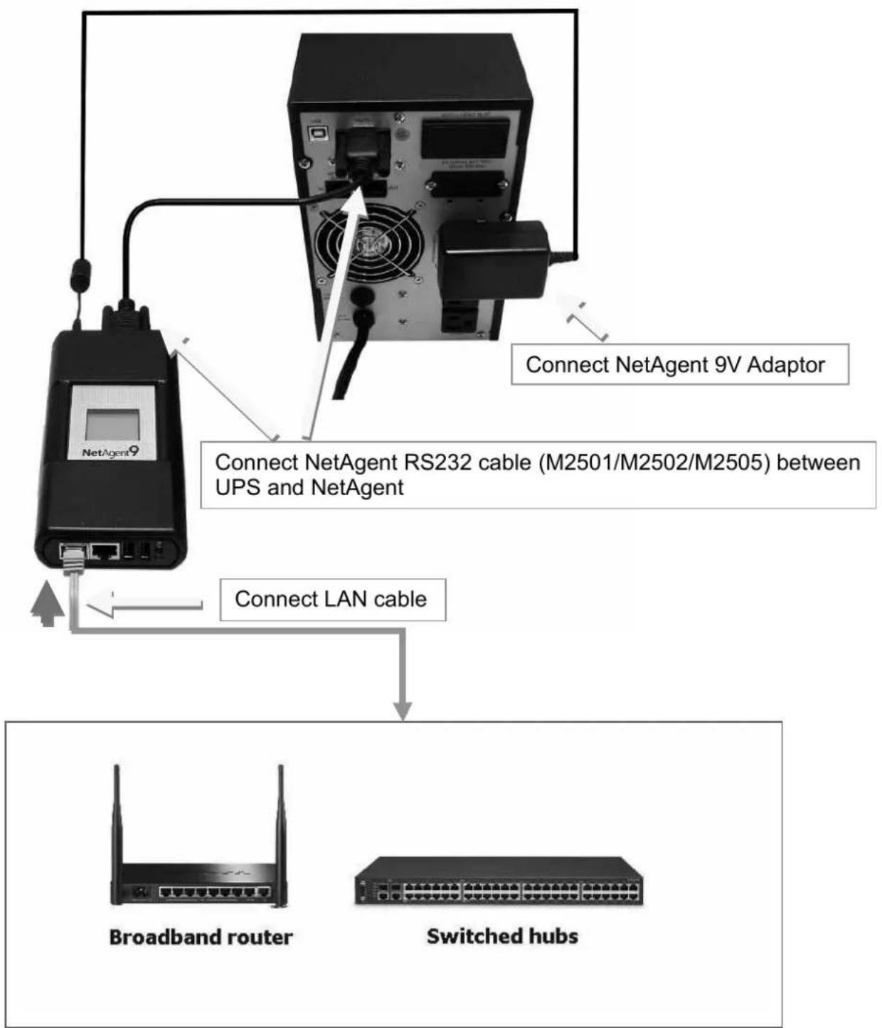
flowchart
graph TD
    A["NetAgent 9V Adaptor"] -->|Connect NetAgent 9V Adaptor| B["RS232 cable (M2501/M2502/M2505) between UPS and NetAgent"]
    B -->|Connect LAN cable| C["Broadband router"]
    C --> D["Switched hubs"]
3.2 Software Installation
NetAgent Utility CD offers several management and shutdown software. Insert CD into CD-ROM and software can be select under 【Program Installation】
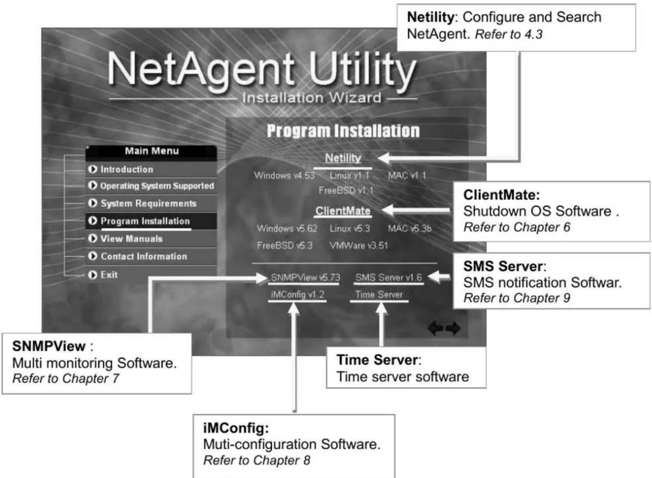
flowchart
graph TD
    A["Program Installation"] --> B["Main Menu"]
    A --> C["Program Installation"]
    A --> D["SNMPView"]
    A --> E["iMConfig"]

    B --> F["Introduction"]
    B --> G["Operating System Supported"]
    B --> H["System Requirements"]
    B --> I["Program Installation"]
    B --> J["View Manuals"]
    B --> K["Contact Information"]
    B --> L["Exit"]

    C --> M["Netility"]
    C --> N["ClientMate"]
    C --> O["SMS Server"]

    D --> P["SNMPView v5.73"]
    D --> Q["iMConfig v1.2"]
    D --> R["SMS Server v1.6"]
    D --> S["Time Server"]

    E --> T["Time Server: Multi-configuration Software.<br>Refer to Chapter 8"]

    U["Netility: Configure and Search NetAgent. Refer to 4.3"] --> A
    V["ClientMate: Shutdown OS Software.<br>Refer to Chapter 6"] --> C
    W["SMS Server: SMS notification Softwar.<br>Refer to Chapter 9"] --> E
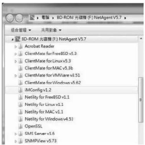
If the PC does not executes CD program automatically, please select from File Management
Chapter 4. NetAgent Setting
4.1 Introduction
NetAgent can be login via web or HyperTerminal with protocol and encryption of HTTP/HTTPS/SSH/Telnet. Enter the IP address of NetAgent to configure and monitor the UPS status.
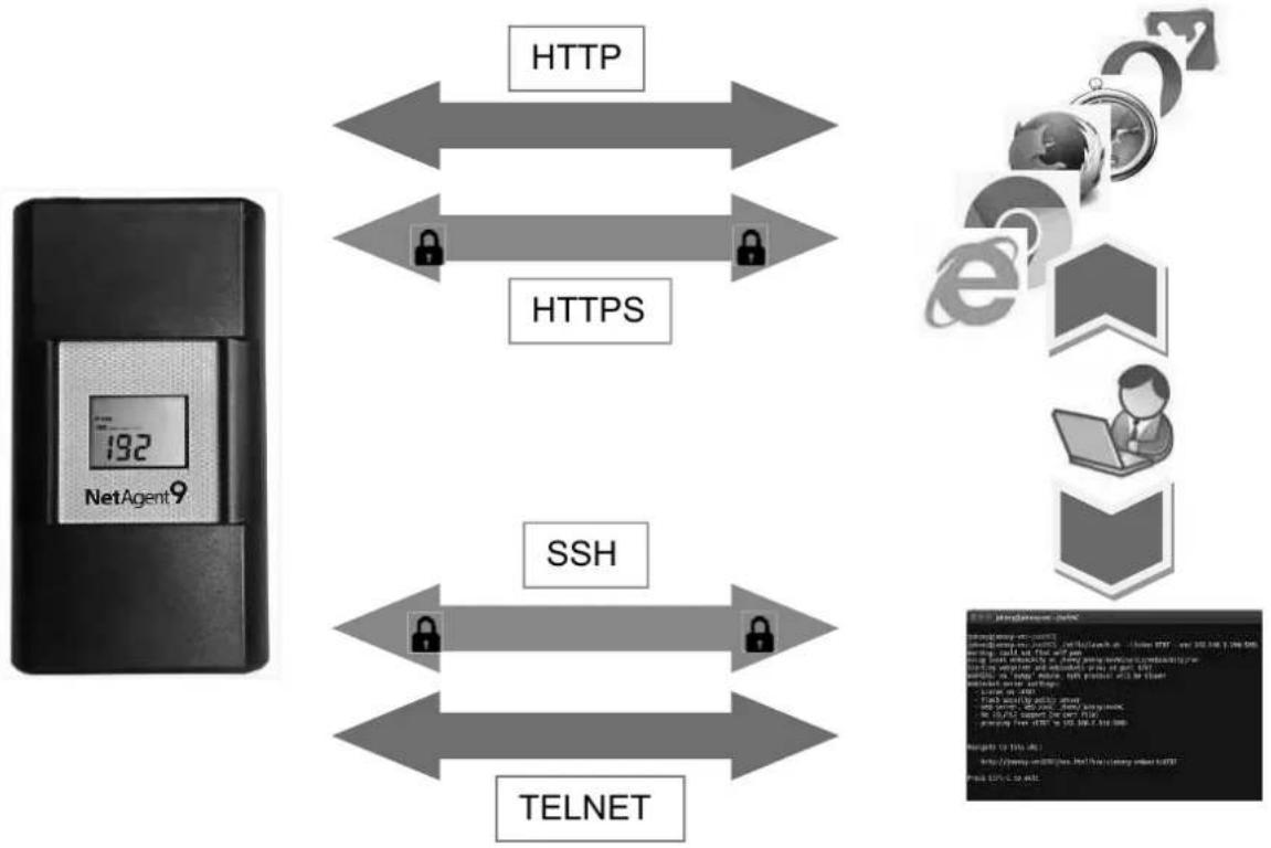
flowchart
graph TD
    A["NetAgent 9"] -->|HTTP| B["HTTPS"]
    A -->|HTTPS| C["SSH"]
    A -->|HTTPS| D["TELNET"]
    B <--> C
    C <--> D
    E["Data Gateway Node"] --> F[Data Gateway Node: http://www.10.1.2.1/10.1.3.1/10.1.4.1/10.1.5.1/10.1.6.1/10.1.7.1/10.1.8.1/10.1.9.1/10.1.10.1/10.1.11.1/10.1.12.1/10.1.13.1/10.1.14.1/10.1.15.1/10.1.16.1/10.1.17.1/10.1.18.1/10.1.19.1/10.1.20.1/10.1.21.1/10.1.22.1/10.1.23.1/10.1.24.1/10.1.25.1/10.1.26.1/10.1.27.1/10.1.28.1/10.1.29.1/10.1.30.1/10.1.31.1/10.1.32.1/10.1.33.1/10.1.34.1/10.1.35.1/10.1.36.1/10.1.37.1/10.1.38.1/10.1.39.1/10.1.40.1/10.1.41.1/10.1.42.1/10.1.43.1/10.1.44.1/10.1.45.1/10.1.46.1/10.1.47.1/10.1.48.1/10.1.49.1/10.1.50.1/10.1.51.1/10.1.52.1/10.1.53.1/10.1.54.1/10.1.55.1/10.1.56.1/10.1.57.1/10.1.58.1/10.1.
4.2 NetAgent Login Procedure
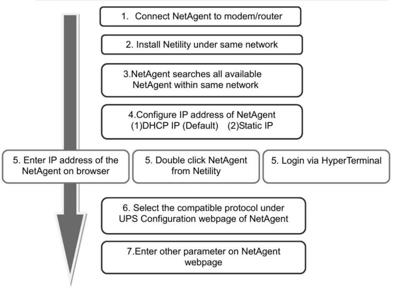
flowchart
graph TD
    A["7. Enter other parameter on NetAgent webpage"] --> B["6. Select the compatible protocol under UPS Configuration webpage of NetAgent"]
    B --> C["5. Double click NetAgent from Netility"]
    C --> D["5. Enter IP address of the NetAgent on browser"]
    D --> E["4. Configure IP address of NetAgent (1)DHCP IP (Default) (2)Static IP"]
    E --> F["3. NetAgent searches all available NetAgent within same network"]
    F --> G["3. Install Netility under same network"]
    G --> H["1. Connect NetAgent to modem/router"]
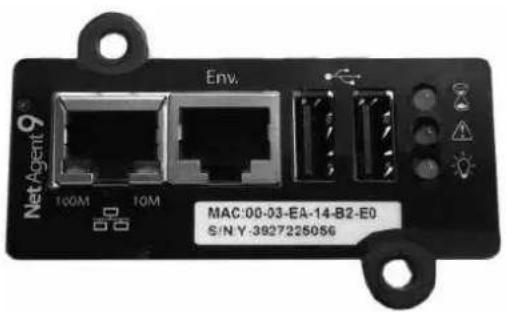
NOTE 1 : Each NetAgent has its unique serial number / MAC address and Password. This is available on the label of each unit. This helps to identify the card information on Netility

NOTE 2 : NetAgent with LCD display may obtain the IP info from it.
Example of LCD display format as below
IP address 192.168.0.70

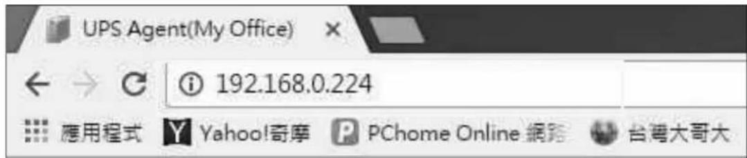
When NetAgent IP is known, enter such IP address on the browser to login. If non-LCD NetAgent model, install Netility software to find and configure its IP address.
4.3 Netility Installation and Setting
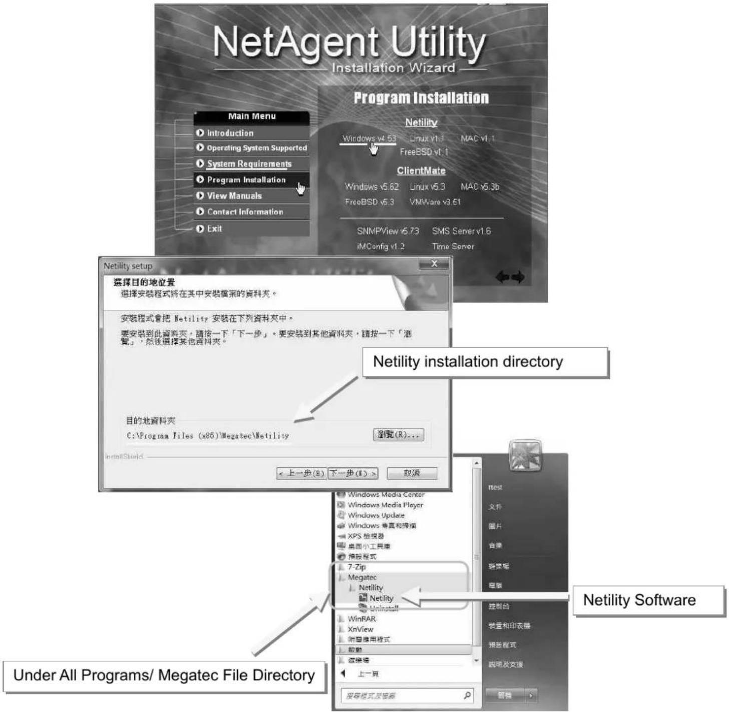
Netility Installation
Netility is tool software that helps the user to search all the available NetAgent within network as well as to configure IP address and firmware upgrade. Mount the NetAgent Utility CD on CD-ROM and click on Program Installation>Netility>Windows v4.53
■ Netility Operation and Setting
Netlity main pages divided into 2 sections:
1. Online NetAgent List 2. Function Selection
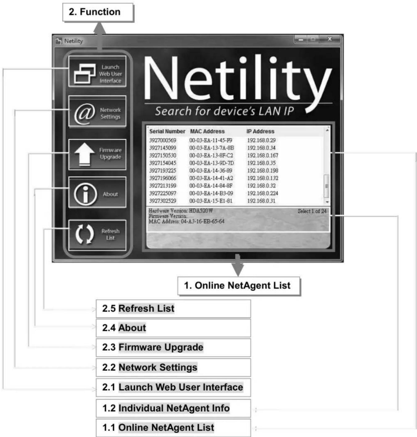
flowchart
graph TD
    A["2. Function"] --> B["Netility"]
    B --> C["Search for device's LAN IP"]
    C --> D["Serial Number MAC Address IP Address"]
    D --> E["3927000569 00-03-EA-11-45-F9 192.168.0.29"]
    D --> F["3927145099 00-03-EA-13-7A-8B 192.168.0.34"]
    D --> G["3927150530 00-03-EA-13-8F-C2 192.168.0.167"]
    D --> H["3927154045 00-03-EA-13-9D-7D 192.168.0.35"]
    D --> I["3927193225 00-03-EA-14-36-89 192.168.0.198"]
    D --> J["3927196066 00-03-EA-14-41-A2 192.168.0.132"]
    D --> K["3927213199 00-03-EA-14-84-8F 192.168.0.32"]
    D --> L["3927225097 00-03-EA-14-B3-09 192.168.0.224"]
    D --> M["3927302529 00-03-EA-15-E1-81 192.168.0.31"]
    C --> N["Hardware Version: HDA520W Select 1 of 24"]
    N --> O["Firmware Version: MAC Address: 04-A3-16-EB-65-64"]
    C --> P["Refresh List"]
    P --> Q["2.5 Refresh List"]
    P --> R["2.4 About"]
    P --> S["2.3 Firmware Upgrade"]
    P --> T["2.2 Network Settings"]
    P --> U["2.1 Launch Web User Interface"]
    P --> V["1.2 Individual NetAgent Info"]
    P --> W["1.1 Online NetAgent List"]
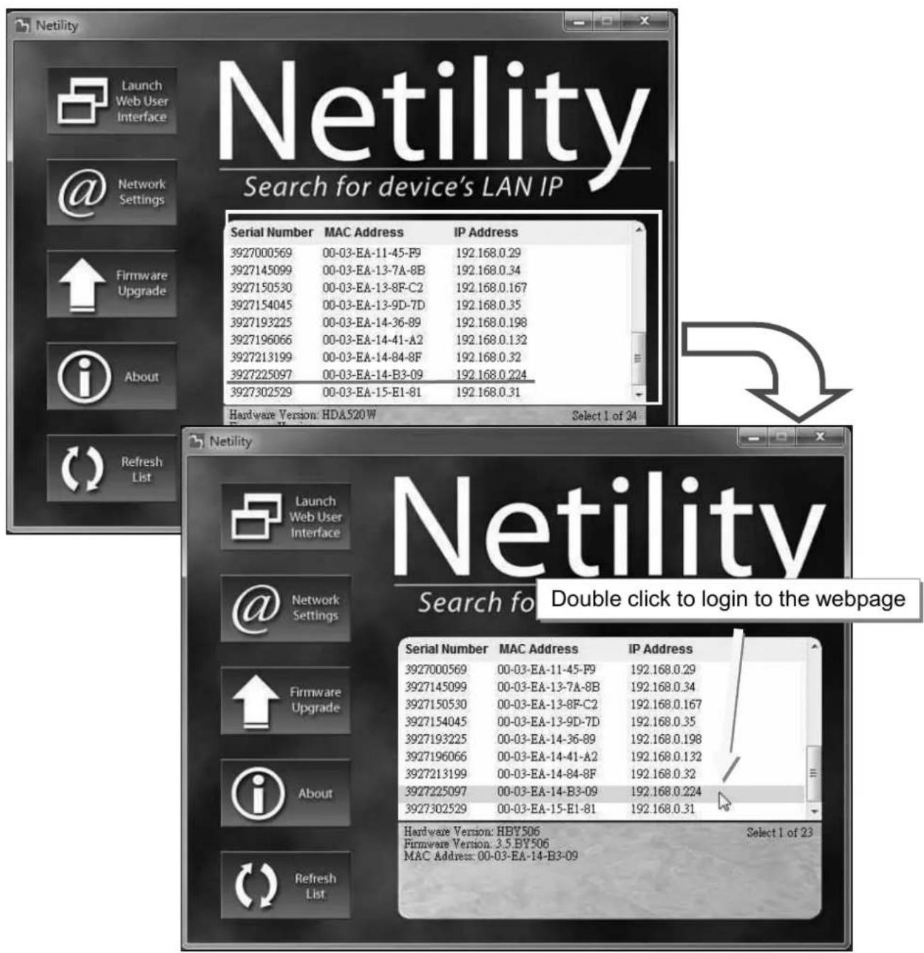
1.1 Online NetAgent List
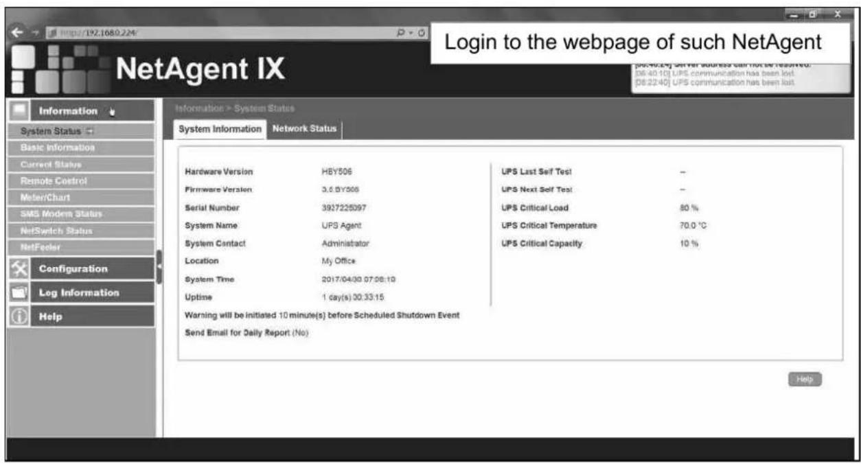
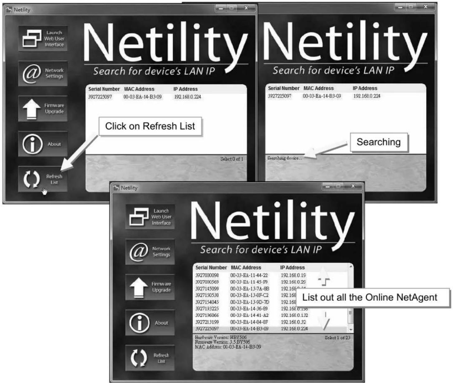
When open up Netility , it automatically searches all the available online NetAegnt within the network with its serial number, IP address, MAC address. Double click on the specific NetAgent with valid IP address, it will direct to the NetAgent's webpage. (List refreshes automatically every 2 minutes)

![NetAgent IX Information > System Status System Information Network Status Hardware Version HBY506 Firmware Version 3.5.BY506 Serial Number 3927225097 System Name UPS Agent System Contact Administrator Location My Office System Time 2017/04/30 06:22:30 Uptime 23:47:34 Warning will be initiated 10 minute(s) before Scheduled Shutdown Event Send Email for Daily Report (No) UPS Last Self Test - UPS Next Self Test - UPS Critical Load 80 % UPS Critical Temperature 70.0 °C UPS Critical Capacity 10 % Latest Events [06:40:24] Server address can not be resolved. [06:40:10] UPS communication has been lost. [08:22:40] UPS communication has been lost.](/content/2026/05/798239/images/3d62474fc6840dcf4b95b3bb5c487e0e2edb9bdac2b2acd9025dbcbcac807b12.jpg)
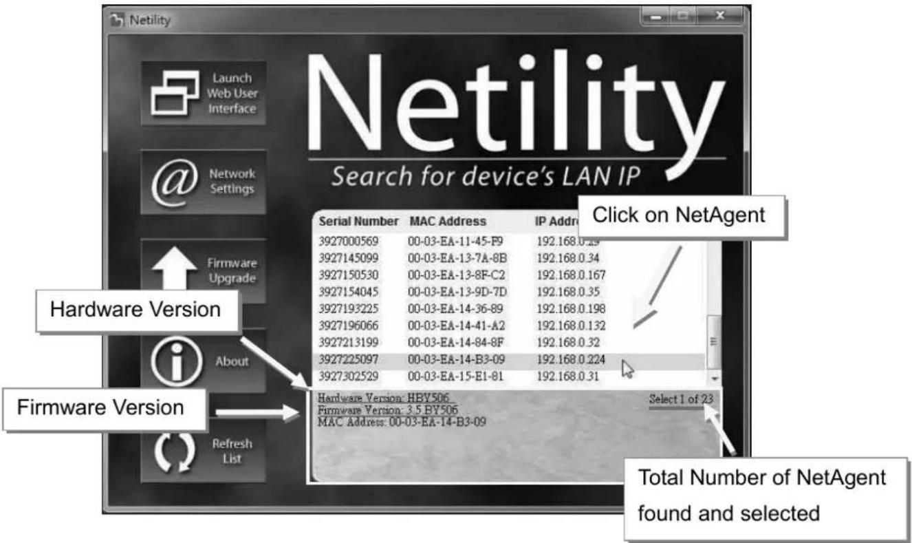
1.2 Individual NetAgent Info
Click on specific NetAgent, the bottom column shows its hardware, firmware version and MAC address. It also shows the total NetAgent number that found by Netility and selected
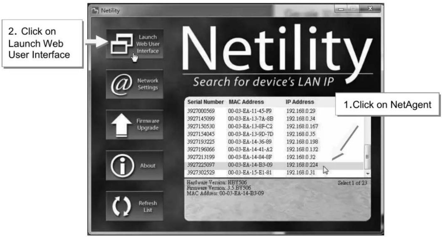
2.1 Launch Web User Interface
Select specific NetAgent from the list and click on Launch Web User Interface to login to the NetAgent's webpage

2.2 Network Settings
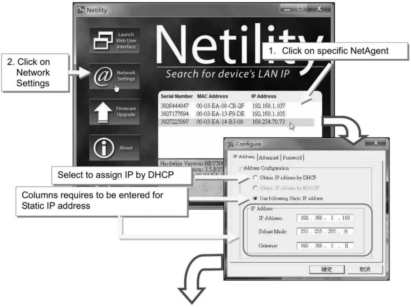
- When connecting the NetAgent for the first time, ensure IP address and other network setting are correctly entered in order to login to the NetAgent's webpage via browser or HyperTerminal
■ When select to obtain IP address by DHCO or BOOTP, IP address and other network parameter will be assign by the network
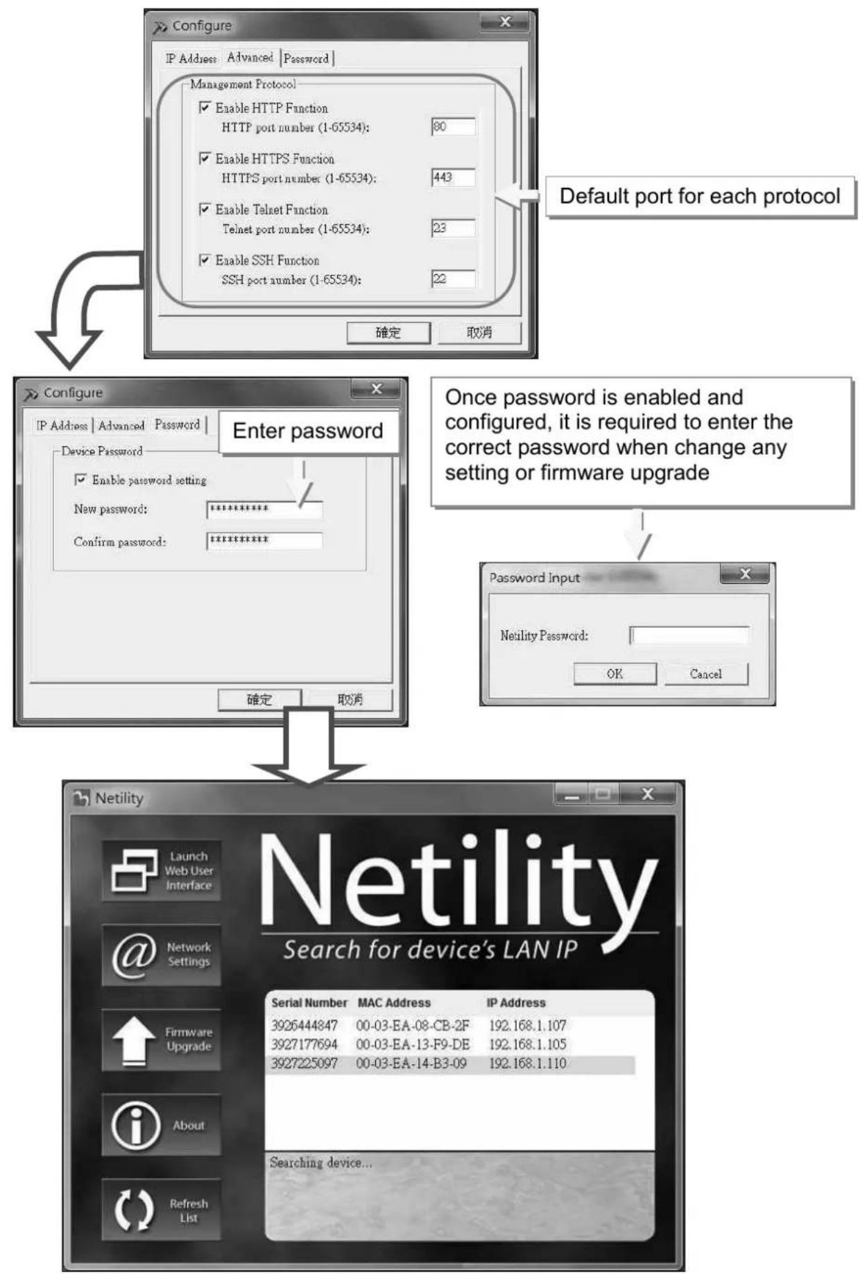
■ NetAgent offers 4 network protocols - HTTP / HTTPS / TELNET / SSH for management with security consideration. If any change on port number, the it require to enter the full IP address with port number in order to login
For example : HTTP port number change to 81
The full address to be enter on browser should be "http://X.X.X.X:81" (X.X.X.X is the IP address of the NetAgent)
For Example : Telnet port number change to 24
The full address to be enter on HyperTerminal should be "http://X.X.X.X 24" (X.X.X.X is the IP address of the NetAgent)
■ When password of the NetAgent is enabled, it is necessary to enter the correct password before making any configuration change and firmware upgrade
2.3 Firmware Upgrade
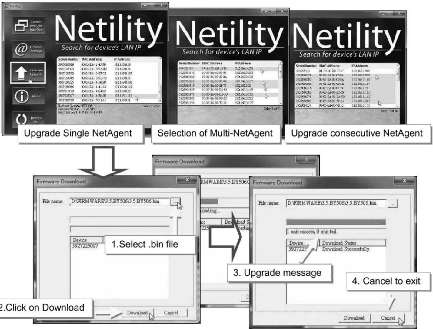
This is to upgrade or re-load the firmware to the NetAgent unit. Firmware version is available on the official website. Ensure to check the NetAgent model, hardware version for the correct firmware version (.bin)
■ Ways to select NetAgent for firmware upgrading
(1) Click on specific NetAgent from the Netility list
(2) Press and hold on CTRL key then select multi NetAgent unit from the list=>This is to upgrade multi units at once
(3) Click on the first NetAgent from the list, then press and hold on SHIFT key as well as click on the last unit of the NetAgent =>This is if all NetAgent from the list are same model
WARING : Please makes sure the multi NetAgent selected are same model
If any failure during firmware upgrading, please upgrade again until it is successfully done
■ While upgrading, red and yellow LED would alternating flashing, or red led flashing. DO NOT remove any power or cable to the NetAgent. Once firmware is successfully upgraded, NetAgent would reboot automatically.
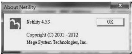
2.4 About
Here shows the current Netility verison
2.5 Refresh List
The list on Netility would refresh every 2 minutes automatically, however, manual refresh is also possible by clicking Refresh List
4.4 NetAgent Setting
4.4.1 Web Interface
NetAgent 9 Mini & NetAgent 9
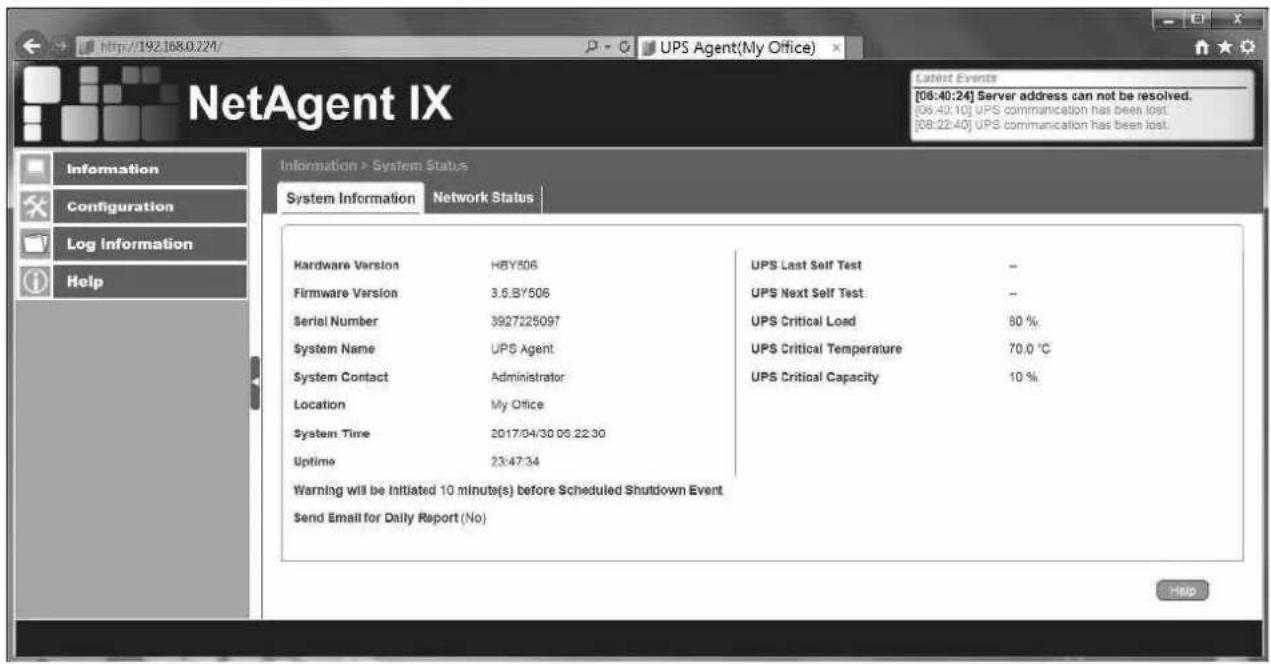
NetAgent Mini & NetAgent II
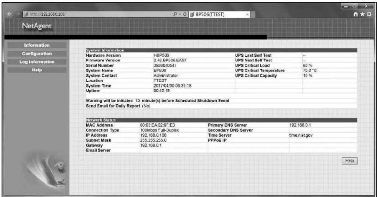
■ Web Interface Display
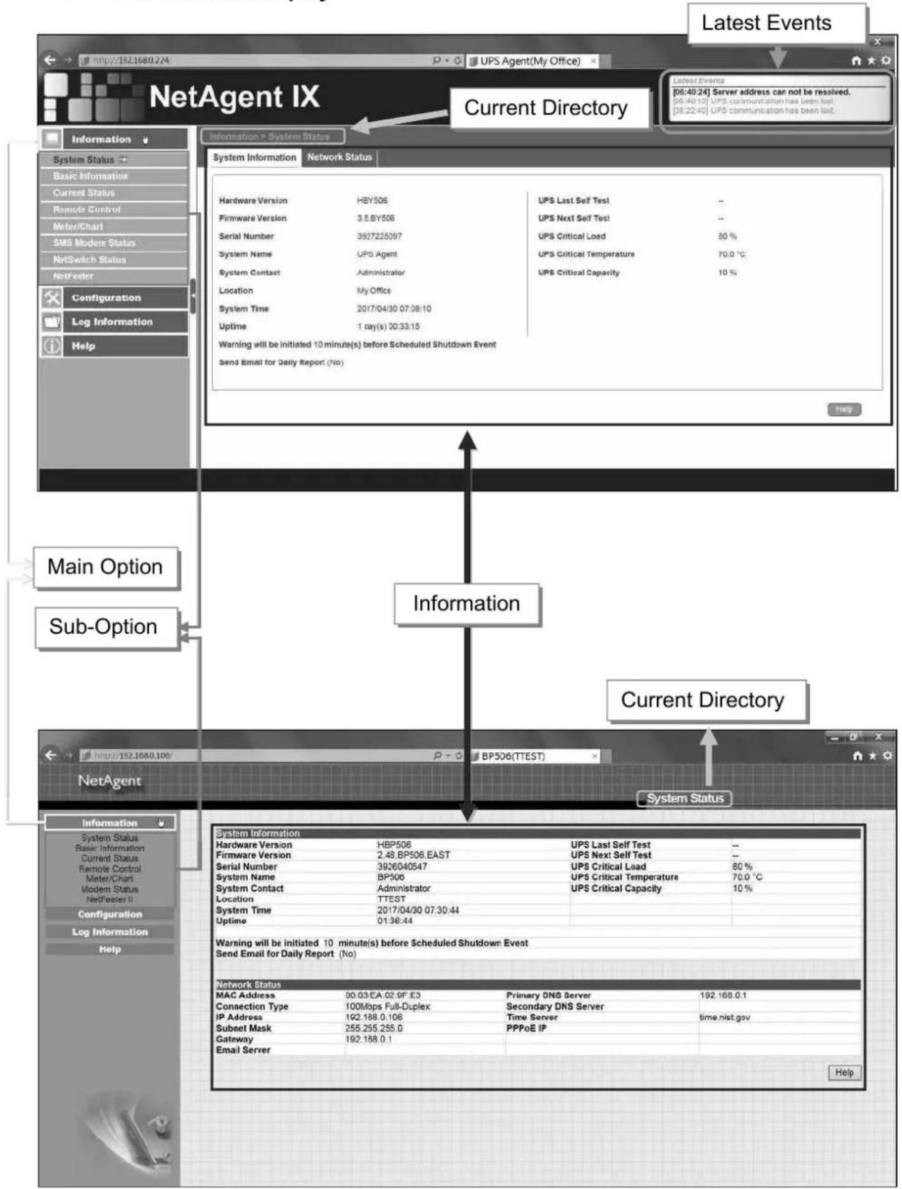
4.4.2 NetAgent Option Directory Structure
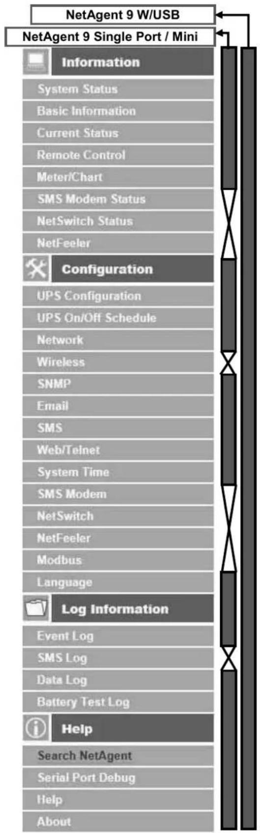
flowchart
graph TD
    A["NetAgent 9 W/USB"] --> B["Configuration"]
    C["NetAgent 9 Single Port / Mini"] --> B
    B --> D["Log Information"]
    D --> E["Help"]
    E --> F["Search NetAgent"]
    E --> G["Serial Port Debug"]
    E --> H["Help"]
    E --> I["About"]
    J["System Status"] --> B
    K["Basic Information"] --> B
    L["Current Status"] --> B
    M["Remote Control"] --> B
    N["Meter/Chart"] --> B
    O["SMS Modem Status"] --> B
    P["NetSwitch Status"] --> B
    Q["NetFeeler"] --> B
    R["UPS Configuration"] --> B
    S["UPS On/Off Schedule"] --> B
    T["Network"] --> B
    U["Wireless"] --> B
    V["SNMP"] --> B
    W["Email"] --> B
    X["SMS"] --> B
    Y["Web/Telnet"] --> B
    Z["System Time"] --> B
    AA["SMS Modem"] --> B
    AB["NetSwitch"] --> B
    AC["NetFeeler"] --> B
    AD["Modbus"] --> B
    AE["Language"] --> B
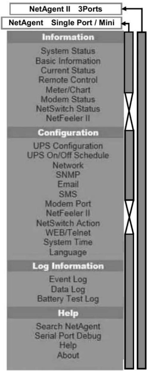
flowchart
graph TD
    A["NetAgent II 3Ports"] --> B["Information"]
    B --> C["System Status"]
    C --> D["Basic Information"]
    D --> E["Current Status"]
    E --> F["Remote Control"]
    F --> G["Meter/Chart"]
    G --> H["Modem Status"]
    H --> I["NetSwitch Status"]
    I --> J["NetFeeler II"]
    B --> K["Configuration"]
    K --> L["UPS Configuration"]
    L --> M["UPS On/Off Schedule"]
    M --> N["Network"]
    N --> O["SNMP"]
    O --> P["Email"]
    P --> Q["SMS"]
    Q --> R["Modem Port"]
    R --> S["NetFeeler II"]
    S --> T["NetSwitch Action"]
    T --> U["WEB/Telnet"]
    U --> V["System Time"]
    V --> W["Language"]
    B --> X["Log Information"]
    X --> Y["Event Log"]
    Y --> Z["Data Log"]
    Z --> AA["Battery Test Log"]
    AA --> AB["Help"]
    AB --> AC["Search NetAgent"]
    AC --> AD["Serial Port Debug"]
    AD --> AE["Help"]
    AE --> AF["About"]
4.4.3 NetAgent Setting Options
■ Information > System Status
- Sysyem Information
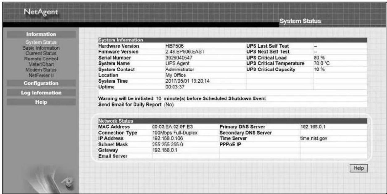
Here shows all the basic information of the NetAgent such as hardware / firmware version; Serial Number; Uptime...etc.
NetAgent 9 Mini & NetAgent 9
![NetAgent IX Information > System Status System Information Network Status Hardware Version HEY506 Firmware Version 3.5.DY506 Serial Number 3927225097 System Name UFS Agent System Contact Administrator Location My Office System Time 2017/04/00 07:08:10 Uptime 1 day(s) 00:33:15 Warning will be initiated 10 minute(s) before Scheduled Shutdown Event Send Email for Daily Report (No) UPS Last Self Test -- UPS Next Self Test -- UPS Critical Load 80 % UPS Critical Temperature 70.0 °C UPS Critical Capacity 10 % Latest Events [06:40:24] Server address can not be resolved. [06:40:10] UPS communication has been lost. [06:22:40] UPS communication has been lost.](/content/2026/05/798239/images/ee96d8a5e54f5654c092dbe2578041138a574f966ec69eac01303473a01a7656.jpg)
NetAgent Mini & NetAgent II

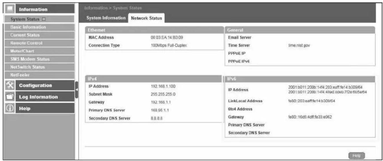
Network Status
This page shows the network information of the NetAgent. With NetAgent9 series which supports IPv6 could work with compatible network appliance.
NetAgent 9 Mini & NetAgent 9
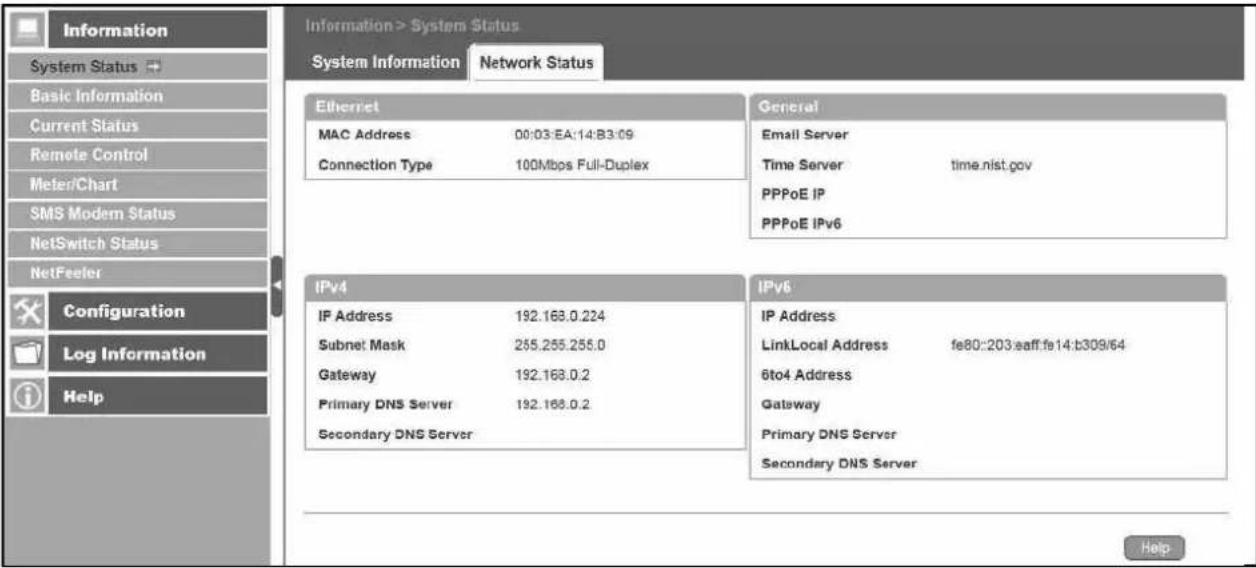
NetAgent Mini & NetAgent II
■ Information > Basic Information
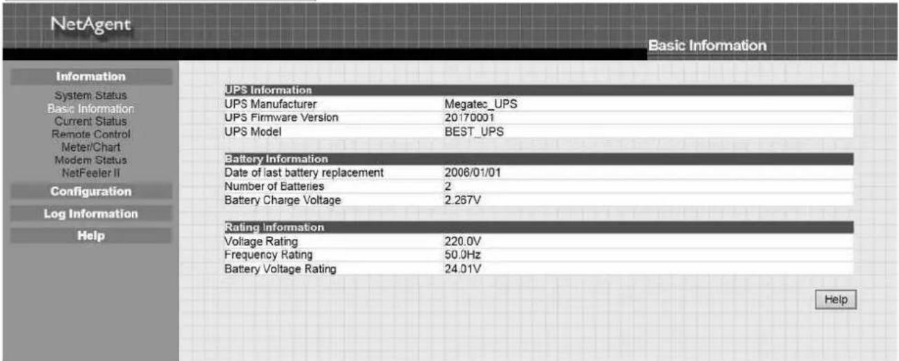
This page shows UPS information/Battery Information/Rating Information. The data is obtained from the reply of UPS or the settings from [UPS Configuration] webpage
NetAgent 9 Mini & NetAgent 9

NetAgent Mini & NetAgent II
■ Information > Current Status
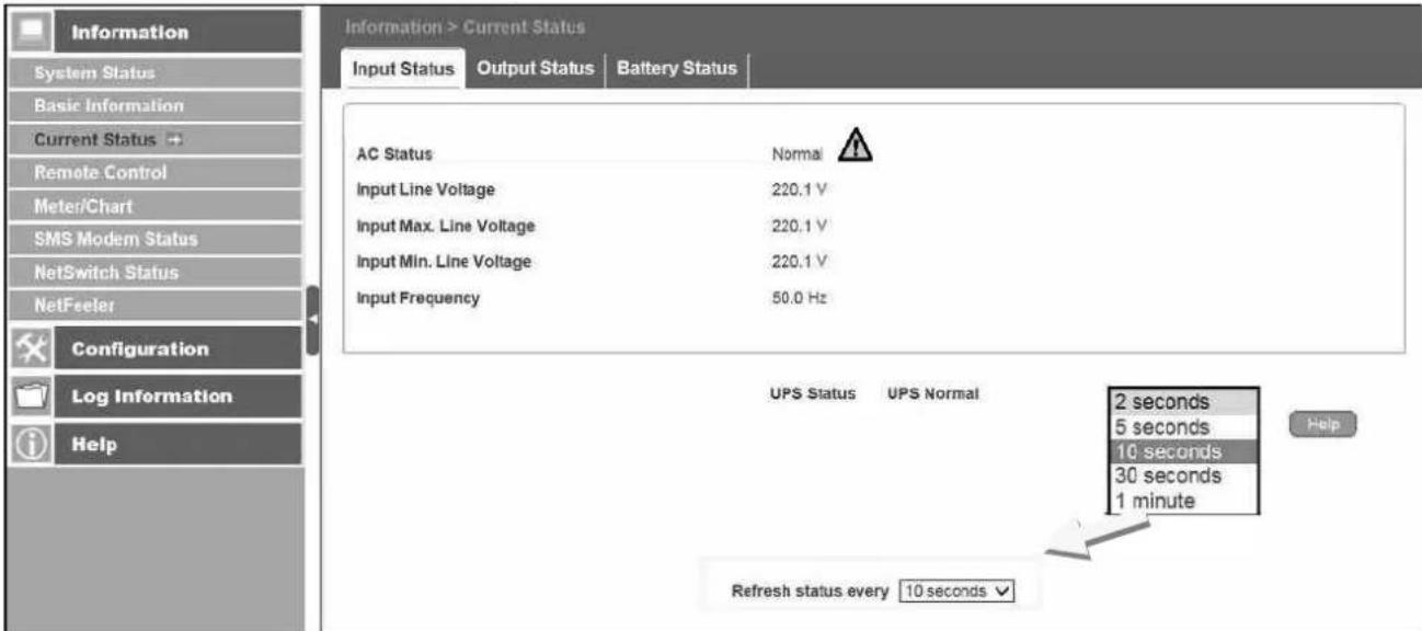
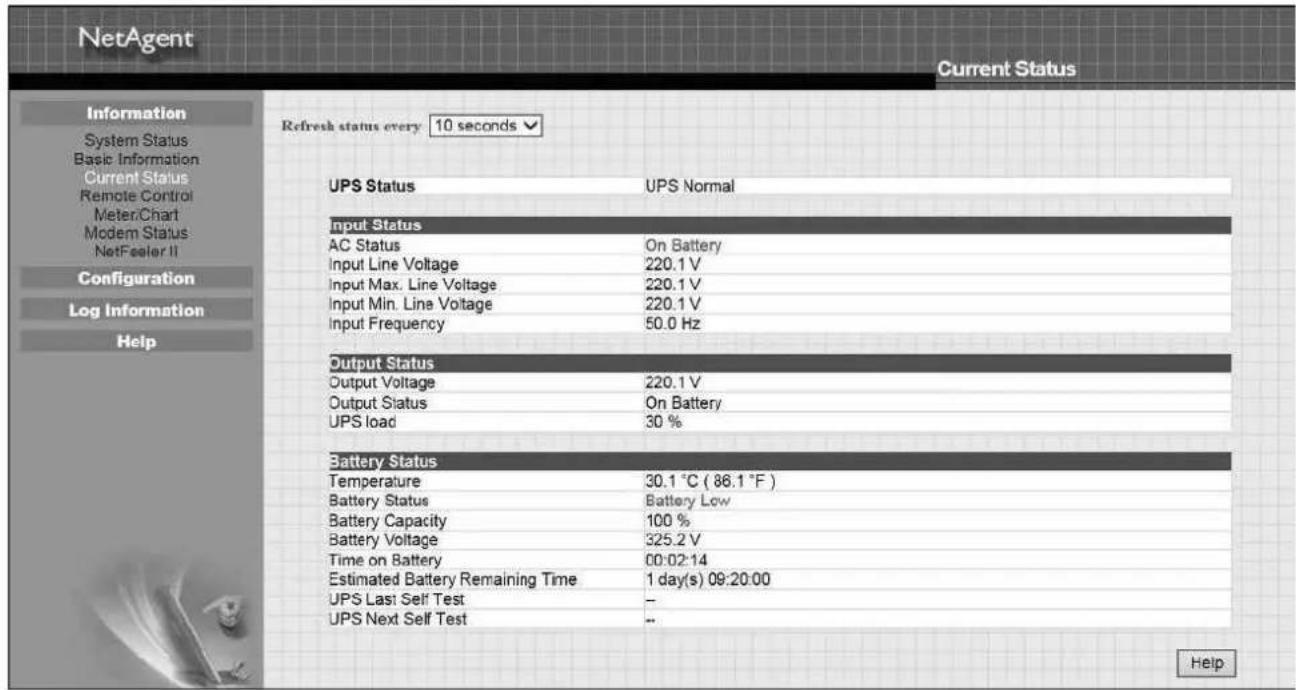
This page shows current UPS Input / Output and Battery Status. Status refresh time can be configured. When abnormal condition occurs, it shows in red.
NetAgent 9 Mini & NetAgent 9
NetAgent Mini & NetAgent II
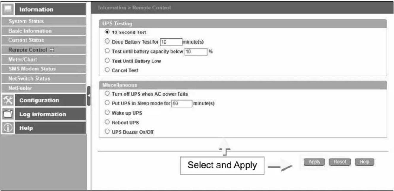
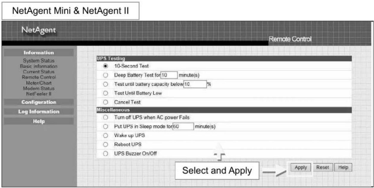
■ Information > Remote Control
Here, user can perform several test to the UPS remotely. Once the option is selected, please click on Apply in order to execute it.
NetAgent 9 Mini & NetAgent 9
■ Information > Meter/Chart
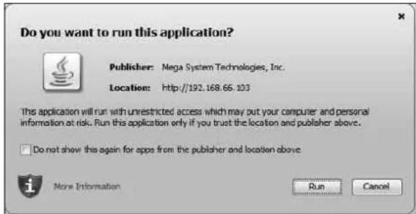
This is to show UPS Input, Output, Temperature, Frequency..etc in graphic or chart. Java is required.
NetAgent 9 Mini & NetAgent 9
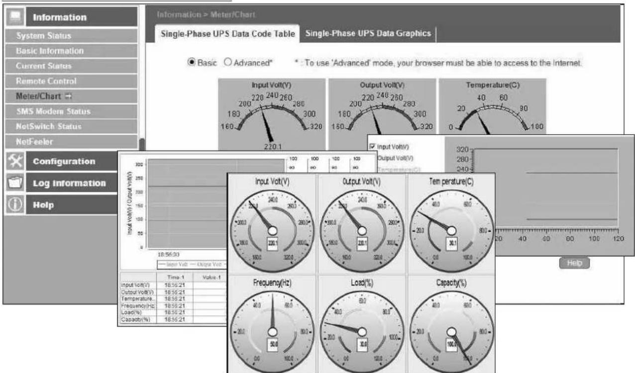
NetAgent Mini & NetAgent II
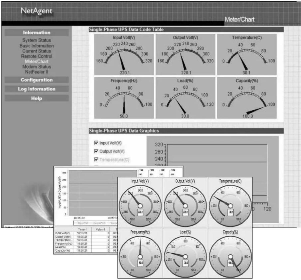
gauge
| Metric | Value | |---|---| | Input Volt(V) | 18.56.21 | | Output Volt(V) | 18.56.21 | | Temperature(C) | 18.56.21 | | Frequency(Hz) | 18.56.21 | | Load(%) | 18.56.21 | | Capacity(%) | 18.56.21 |■ Information > SMS Modem Status
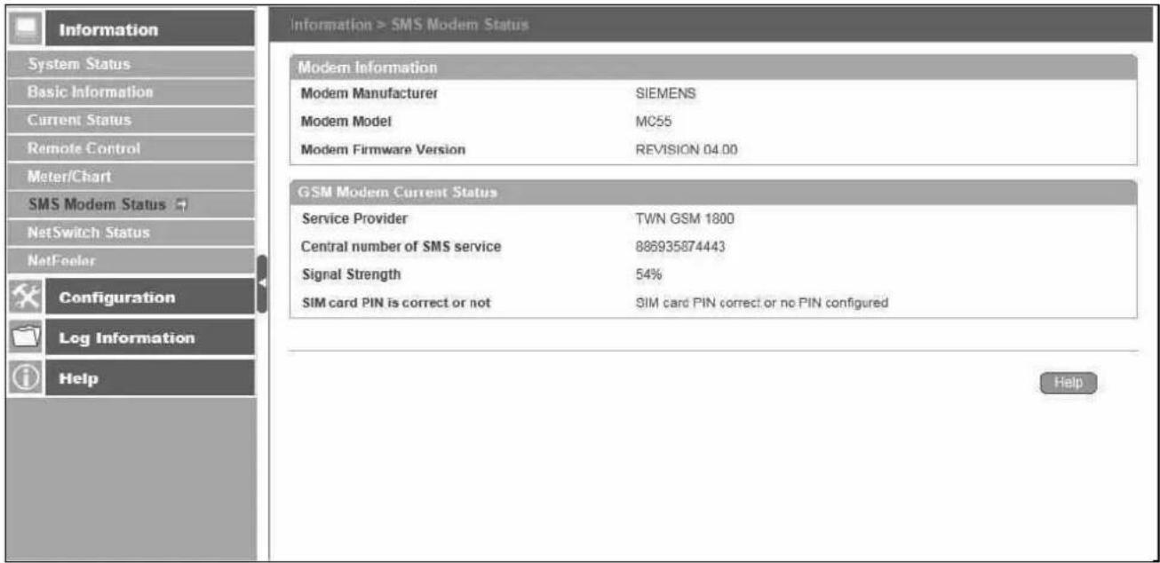
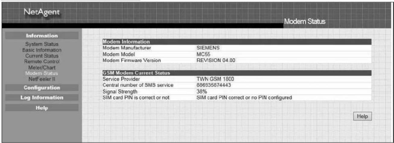
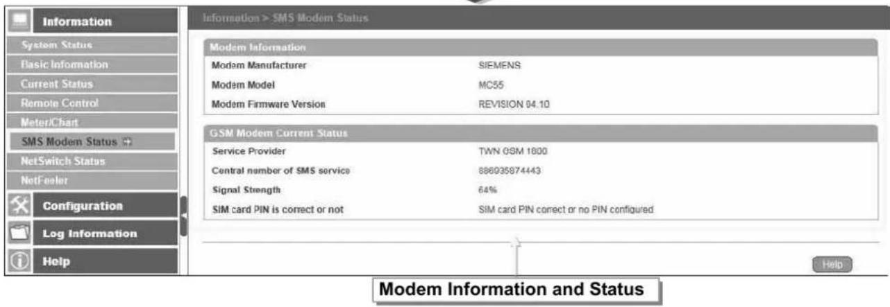
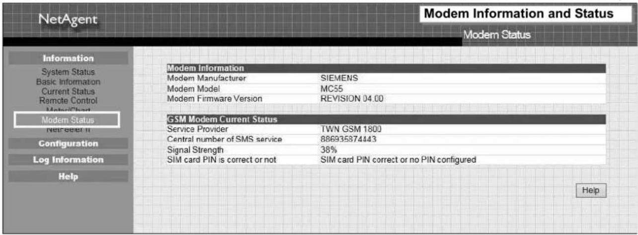
This page shows the Modem status when GPRS modem is connecting with NetAgent 9 or NetAgent II (3 Ports)
NetAgent 9
NetAgent II 3 Ports
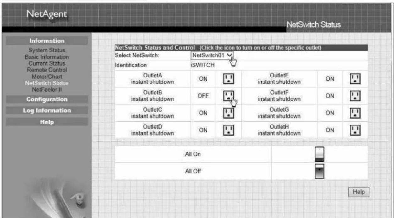
■ Information > NetSwitch Status
If NetAgent connects with our NetSwitch to control outlet remotely, this page shows the status of each outlet and each outlet can be turn On/Off manually
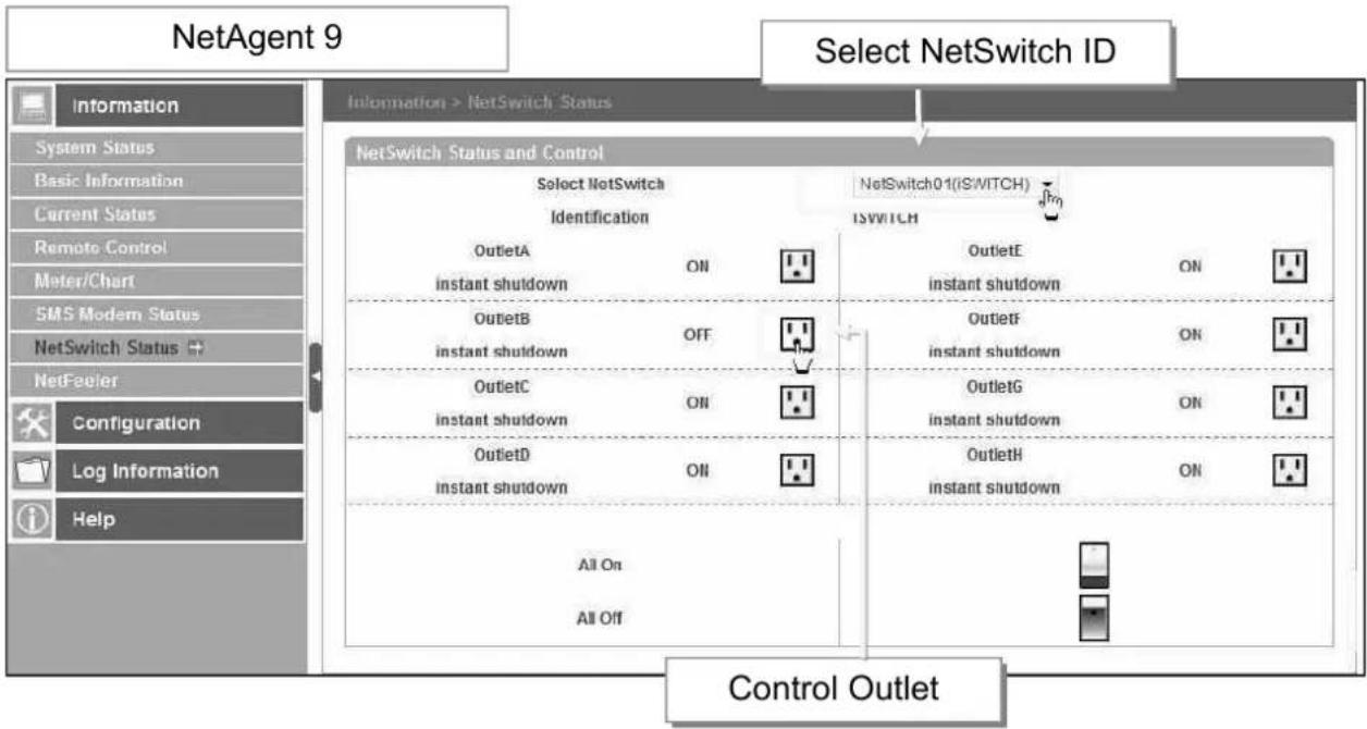
flowchart
graph TD
    A["NetAgent 9"] --> B["Information"]
    A --> C["System Status"]
    A --> D["Basic Information"]
    A --> E["Current Status"]
    A --> F["Remote Control"]
    A --> G["Meter/Chart"]
    A --> H["SMS Modem Status"]
    A --> I["NetSwitch Status"]
    A --> J["NetFeuler"]
    A --> K["Configuration"]
    A --> L["Log Information"]
    A --> M["Help"]
    N["Select NetSwitch ID"] --> O["NetSwitch01(IS/WITCH)"]
    O --> P["Identification"]
    P --> Q["OutletA ON"]
    P --> R["OutletB OFF"]
    P --> S["OutletC ON"]
    P --> T["OutletD ON"]
    O --> U["ISWITCH"]
    U --> V["OutletE ON"]
    U --> W["OutletF ON"]
    U --> X["OutletG ON"]
    U --> Y["OutletH ON"]
    P --> Z["Instant shutdown"]
    P --> AA["Instant shutdown"]
    P --> AB["Instant shutdown"]
    P --> AC["Instant shutdown"]
    P --> AD["Instant shutdown"]
    P --> AE["Instant shutdown"]
    P --> AF["Instant shutdown"]
    P --> AG["Instant shutdown"]
    P --> AH["Instant shutdown"]
    P --> AI["Instant shutdown"]
    P --> AJ["Instant shutdown"]
    P --> AK["Instant shutdown"]
    P --> AL["Instant shutdown"]
    P --> AM["Instant shutdown"]
    P --> AN["Instant shutdown"]
    P --> AO["Instant shutdown"]
    P --> AP["Instant shutdown"]
    P --> AQ["Instant shutdown"]
    P --> AR["Instant shutdown"]
    P --> AS["Instant shutdown"]
    P --> AT["Instant shutdown"]
    P --> AU["Instant shutdown"]
    P --> AV["Instant shutdown"]
    P --> AW["Instant shutdown"]
    P --> AX["Instant shutdown"]
    P --> AY["Instant shutdown"]
    P --> AZ["Instant shutdown"]
    P --> BA["Instant shutdown"]
    P --> BB["Instant shutdown"]
    P --> BC["Instant shutdown"]
    P --> BD["Instant shutdown"]
    P --> BE["Instant shutdown"]
    P --> BF["Instant shutdown"]
    P --> BG["Instant shutdown"]
    P --> BH["Instant shutdown"]
    P --> BI["Instant shutdown"]
    P --> BJ["Instant shutdown"]
    P --> BK["Instant shutdown"]
    P --> BL["Instant shutdown"]
    P --> BM["Instant shutdown"]
    P --> BN["Instant shutdown"]
    P --> BO["Instant shutdown"]
    P --> BP["Instant shutdown"]
    P --> BQ["Instant shutdown"]
    P --> BR["Instant shutdown"]
    P --> BS["Instant shutdown"]
    P --> BT["Instant shutdown"]
    P --> BU["Instant shutdown"]
    P --> BV["Instant shutdown"]
    P --> BW["Instant shutdown"]
    P --> BX["Instant shutdown"]
    P --> BY["Instant shutdown"]
    P --> BZ["Instant shutdown"]
    P --> CA["Instant shutdown"]
    P --> CB["Instant shutdown"]
    P --> CC["Instant shutdown"]
    P --> CD["Instant shutdown"]
    P --> CE["Instant shutdown"]
    P --> CF["Instant shutdown"]
    P --> CG["Instant shutdown"]
    P --> CH["Instant shutdown"]
    P --> CI["Instant shutdown"]
    P --> CJ["Instant shutdown"]
    P --> CK["Instant shutdown"]
    P --> CL["Instant shutdown"]
    P --> CM["Instant shutdown"]
    P --> CN["Instant shutdown"]
    P --> CO["Instant shutdown"]
    P --> CP["Instant shutdown"]
    P --> CQ["Instant shutdown"]
    P --> CR["Instant shutdown"]
    P --> CS["Instant shutdown"]
    P --> CT["Instant shutdown"]
    P --> CU["Instant shutdown"]
    P --> CV["Instant shutdown"]
    P --> CW["Instant shutdown"]
    P --> CX["Instant shutdown"]
    P --> CY["Instant shutdown"]
    P --> CZ["Instant shutdown"]
    P --> DA["Instant shutdown"]
    P --> DB["Instant shutdown"]
    P --> DC["Instant shutdown"]
    P --> DD["Instant shutdown"]
    P --> DE["Instant shutdown"]
    P --> DF["Instant shutdown"]
    P --> DG["Instant shutdown"]
    P --> DH["Instant shutdown"]
    P --> DI["Instant shutdown"]
    P --> DJ["Instant shutdown"]
    P --> DK["Instant shutdown"]
NetAgent II 3 Ports
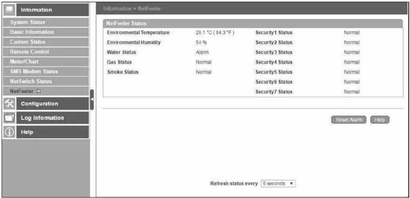
■ Information > NetFeeler (NetFeeler II)
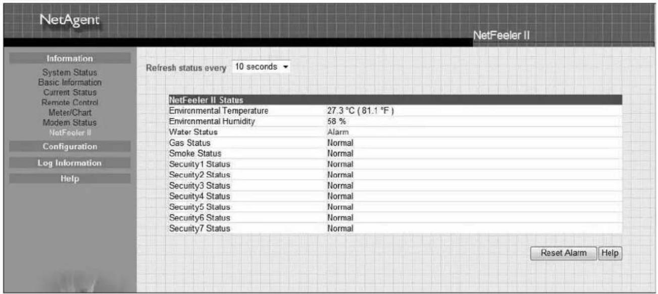
This page shows the environmental status when NetFeeler/ NetFeeler II and its accessories are connected with NetAent.
NetAgent 9 3PORTS
NetAgent II 3 Ports
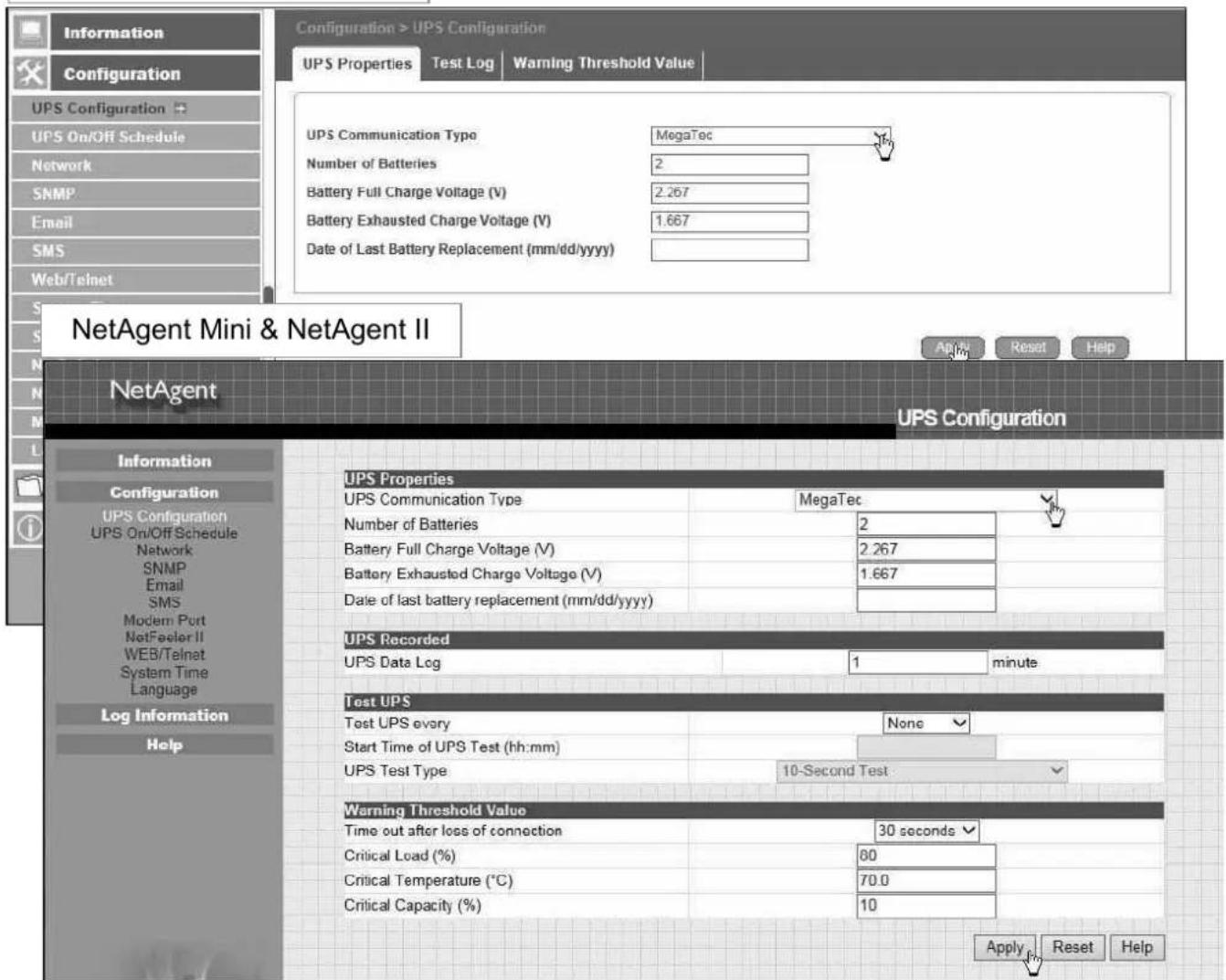
■ Configuration > UPS Configuration
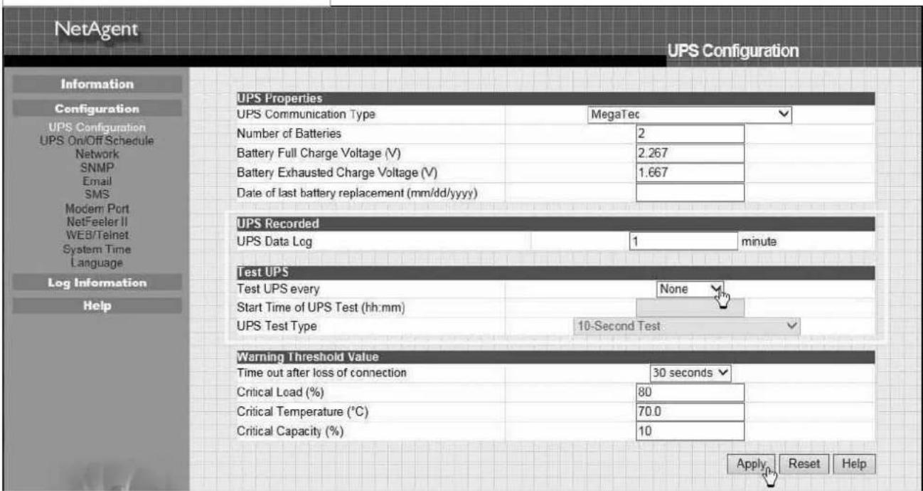
● UPS Properties (Please refer to your UPS specification)
UPS Communication Type:
In order to let NetAgent and UPS to establish the communication, select the compatible protocol which your UPS supported from the list. Wrong protocol selected would cause no communication at all. (Megatec is default protocol)
Number of Batteries :
Enter the number of battery that the UPS has.
Battery Full Charge Voltage (V) :
Enter the number of the full charged voltage per battery cell. (2.267 is default, this is recommended not to be change)
Battery Exhausted Charge Voltage(V):
Enter the number of exhausted voltage per battery cell. (1.667 is default, this is recommended not to be change)
Date of Last Battery replacement(mm/dd/yyyy) :
Enter the date of last battery replacement for record
NetAgent 9 Mini & NetAgent 9
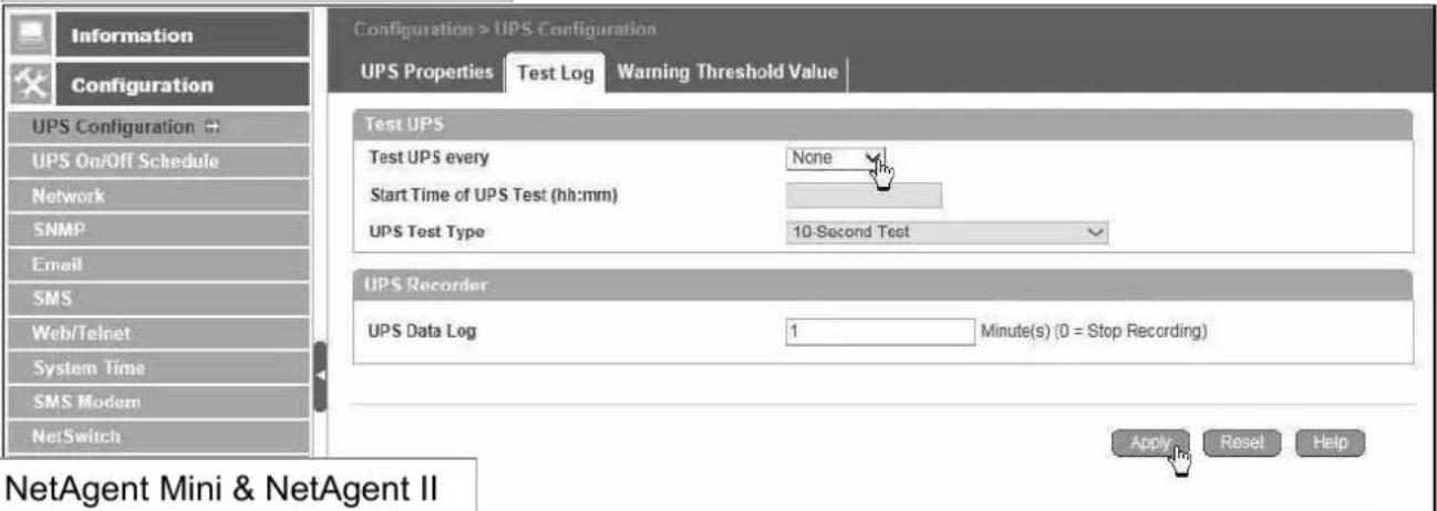
- Test Log
Test UPS Every :
Week /2 Weeks/ Month / Quarter UPS can be selected
Start Time of UPS Test (hh:mm):
To enter the time to begin the test
UPS Test Type :
Test option can be select from the drop down list
UPS Data Log :
To enter the time interval to refreshing data
NetAgent 9 Mini & NetAgent 9
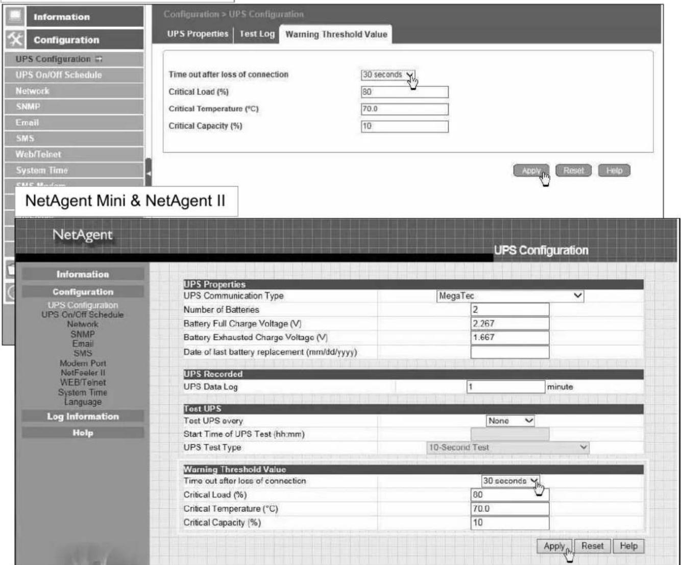
● Warning Threshold Values
Time out after loss of connection :
Send warning alarm when NetAgent and UPS lost connection at this configured time Critical Load(%) :
When loading reaches at this % configured, NetAgent will send warning alarm
UPS Temperature (°C):
When UPS temperature reaches at this degree configured, NetAgent will send warning alarm
Critical Capacity (%):
When UPS battery capacity reaches at this % configured, NetAgent will send warning alarm
NetAgent 9 Mini & NetAgent 9
■ Configuration > UPS On/Off Schedule
- UPS Action
When selected event happens at configured time range, UPS will be shut down
![NetAgent 9 Mini & NetAgent 9 Configuration > UPS On/Off Schedule 1.Time Range 2.Event 3.Time to turn off UPS 4.Add new event UPS Action Weekly Schedule Data Schedule Wake On Lan During 00:00 - 23:59, if UPS Load Overrun occur, then turn off UPS after 0 minutes. Add No. During Time Interval(HR:MM) Event Delay Time (Min) 1 00:00 - 23:59 UPS Load Overrun 10 [Delete] 2 00:00 - 23:59 AC Power Failed 8 [Delete] 3 00:00 - 23:59 UPS Battery Low 15 [Delete] 4 00:00 - 23:59 UPS Temperature Overrun 3 [Delete] Event schedule list Apply Reset Help Log Information Help](/content/2026/05/798239/images/1143e5f7b3fd17066b3b38bb13dc38abe6be13d63402a6ae8cfd585e7b459113.jpg)
NetAgent Mini & NetAgent II
![NetAgent UPS On/Off Schedule Information Configuration UPS Configuration UPS On/Off Schedule Network SNMP Email SMS Modem Port NetFeeler II WEB/Telnet System Time Language Log Information Help UPS Action During 00:00 - 23:59 , if UPS Load Overrun No. During Time Interval(HH:MM) Event Delay Time (Min) 1 00:00 - 23:59 UPS Load Overrun 10 [Delete] 2 00:00 - 23:59 AC Power Failed 8 [Delete] 3 00:00 - 23:59 UPS Battery Low 15 [Delete] 4 00:00 - 23:59 UPS Temperature Overrun 3 [Delete] Weekly Schedule Turn On (hh:mm) Turn Off (hh:mm) Sunday Monday Tuesday Wednesday Thursday Friday Saturday Event schedule list 12:55 Date Schedule Date (yyyy/mm/dd) Turn On (hh:mm) Turn Off (hh:mm) Apply Reset Help](/content/2026/05/798239/images/0547f1458df1c97b6f265562cd2ece634ed0185def6d9966c463616cfd838a44.jpg)
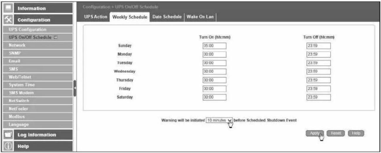
- Weekly Schedule
This section is to set the time to turn on/off the UPS each day in the week.
NetAgent 9 Mini & NetAgent 9
NetAgent Mini & NetAgent II
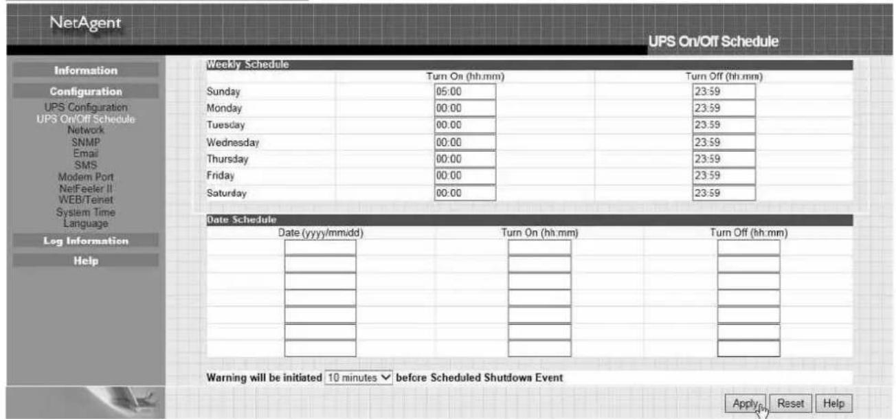
- Date Schedule
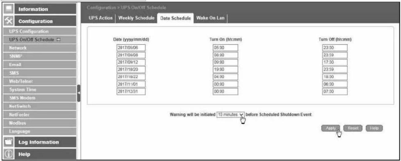
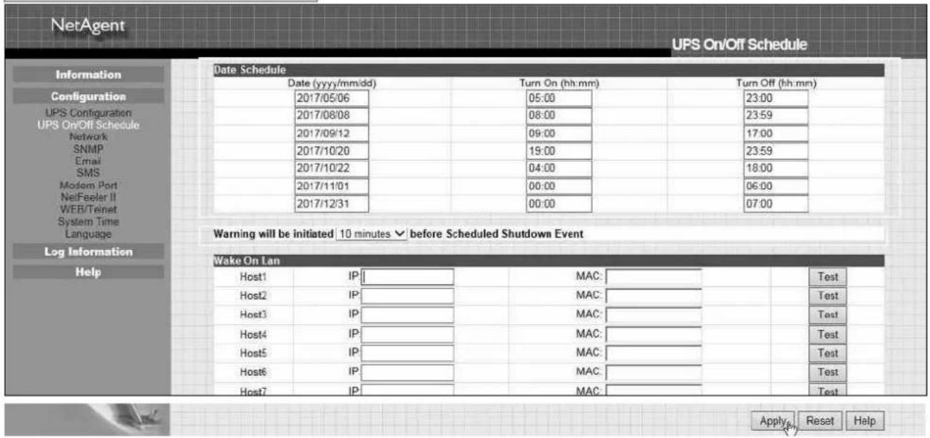
This section is to set the time to turn on/off the UPS on particular days.
(e.g, holidays.) The settings here override the settings in Weekly Schedule.
Warning will be initiated before Schedule shutdown event
NetAgent will send a warning message before a scheduled shutdown. This section sets the delay time period after the message is sent and before the scheduled shutdown is started.
NetAgent 9 Mini & NetAgent 9
NetAgent Mini & NetAgent II
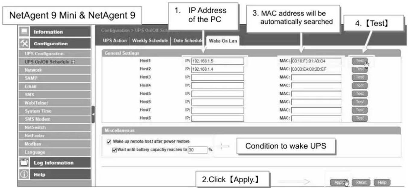
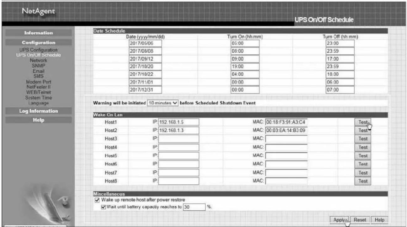
- Wake On Lan
This section is to wake the PC within the network when AC recovery, or, when battery capacity reaches at configured %. (Make sure the PC has such function supported and configure as "Enabled" under BIOS.) Enter the IP address of that PC and system would search its IP accordingly.
flowchart
graph TD
    A["Configuration > UPS On/Off Schedule"] --> B["IP Address of the PC"]
    B --> C["MAC address will be automatically searched"]
    C --> D["General Settings"]
    D --> E["Host1: IP: 192.168.1.5"]
    D --> F["Host2: IP: 192.168.1.4"]
    D --> G["Host3: IP: "]
    D --> H["Host4: IP: "]
    D --> I["Host5: IP: "]
    D --> J["Host6: IP: "]
    D --> K["Host7: IP: "]
    D --> L["Host8: IP: "]
    E --> M["MAC: 00.18:F3:91:A3:C4"]
    F --> N["MAC: 00.03:EA:08:20:EF"]
    G --> O["MAC: "]
    H --> P["MAC: "]
    I --> Q["MAC: "]
    J --> R["MAC: "]
    K --> S["MAC: "]
    L --> T["MAC: "]
    M --> U["Miscellaneous"]
    N --> U
    O --> U
    P --> U
    Q --> U
    R --> U
    S --> U
    T --> U
    U --> V["Wake up remote host after power restore"]
    V --> W["Condition to wake UPS"]
    W --> X["2.Click【Apply.】"]
NetAgent Mini & NetAgent II
■ Configuration > Network
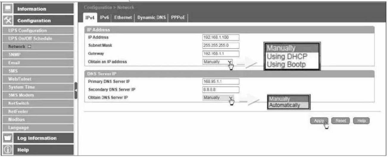
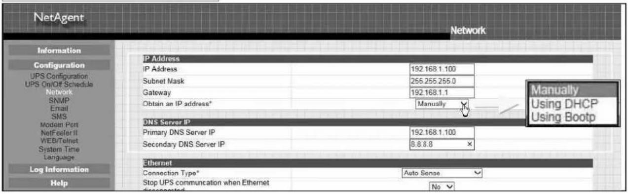
This page is to set NetAgent Network settings.
IPv4
NetAgent and DNS IP address can be obtained by drop down list with option of Manually, Using DHCP, or Bootp. If the IP address and DNS has been configured on Netility, then info will automatically show here
NetAgent 9 Mini & NetAgent 9
NetAgent Mini & NetAgent II
IPv6
All NetAgent 9 series supports IPv6. IP address can be obtained from the drop down list with option of (Automatic/Stateless DHCPV6/DHCPV6/Manual)
Once click on Apply, NetAgent will reboot
NetAgent 9 Mini & NetAgent 9
![Information Configuration UPS Configuration UPS On/Off Schedule Network SNMP Email SMS Web/Telnet System Time SMS Modem NetSwitch NetFeeler Modbus Language Log Information Help Configuration > Network IPv4 IPv6 Ethernet Dynamic DNS PPPoE IP Address IP Address [2001:b011:200b:14f4:49ad ddeb.7f2] IPv6 Prefix 64 Gateway [fe80::16d6:4df fe33:e962] Obtain an address * Automatic Router Discovery Autoresend Yes Maximum Number of IPv6 Prefix $ Multicast Address [FF1E::1] : 5000 Automatic Stateless DHCPV6 DHCPV6 Manual DNS Server IP Primary DNS Server 2301:b000:168::1 Secondary DNS Server 2301:b000:168::1 * : System will reboot when these items have been Applied. Apply Reset Help](/content/2026/05/798239/images/51a287e9456e200f2dde5f6eb8860472393df5187e2a5592ee475f183527bfa1.jpg)
![http://2001.b011/206b.14/4:203:seaff.fel4b309/ UPS Agent(My Office) NetAgent IX Last Event [05:25:37] Internal diagnostic self-test passed. [05:25:13] Internal diagnostic self-test failed. [05:24:28] Utility power has been restored. Information System Status Basic Information Current Status Primary Control Information > Current Status Input Status Output Status Battery Status AC Status Normal](/content/2026/05/798239/images/5b8296b76d79fb6d750238f89e666874ab524e8e1cd788a396e22fae551e81f6.jpg)
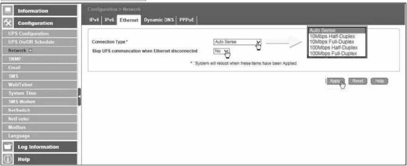
- Ethernet
Connection Type
This section is to set communication speed between NetAgent and Network.
Once click on Apply, NetAgent will reboot
Stop UPS communication when Ethernet disconnected
This section is to set if to stop UPS communication when NetAgent disconnects with Ethernet
NetAgent 9 Mini & NetAgent 9
NetAgent Mini & NetAgent II

- Dynamic DNS
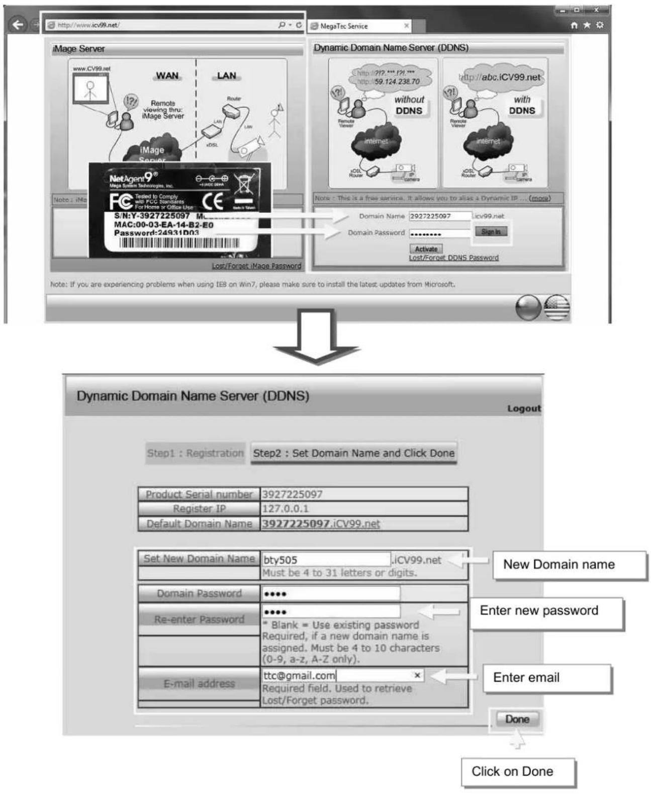
This is a free service that allows the user to alias a dynamic IP address to a static hostname. Ensure account/password has been registered from the DNS service provider
Service Provider
Dynamic DNS providers can be select from the list
Domain Name
This is the Domain Name you have created from the above selected DDNS provider Login Name
This is the Login / Account name that you have created with the selected DDNS provider.
Login Password:
Enter the Password you have assigned to your DDNS Account.
Use external STUN server to get Public IP to register
Choose Yes to ensure that NetAgent uses the WAN / Public IP to update the selected DDNS server
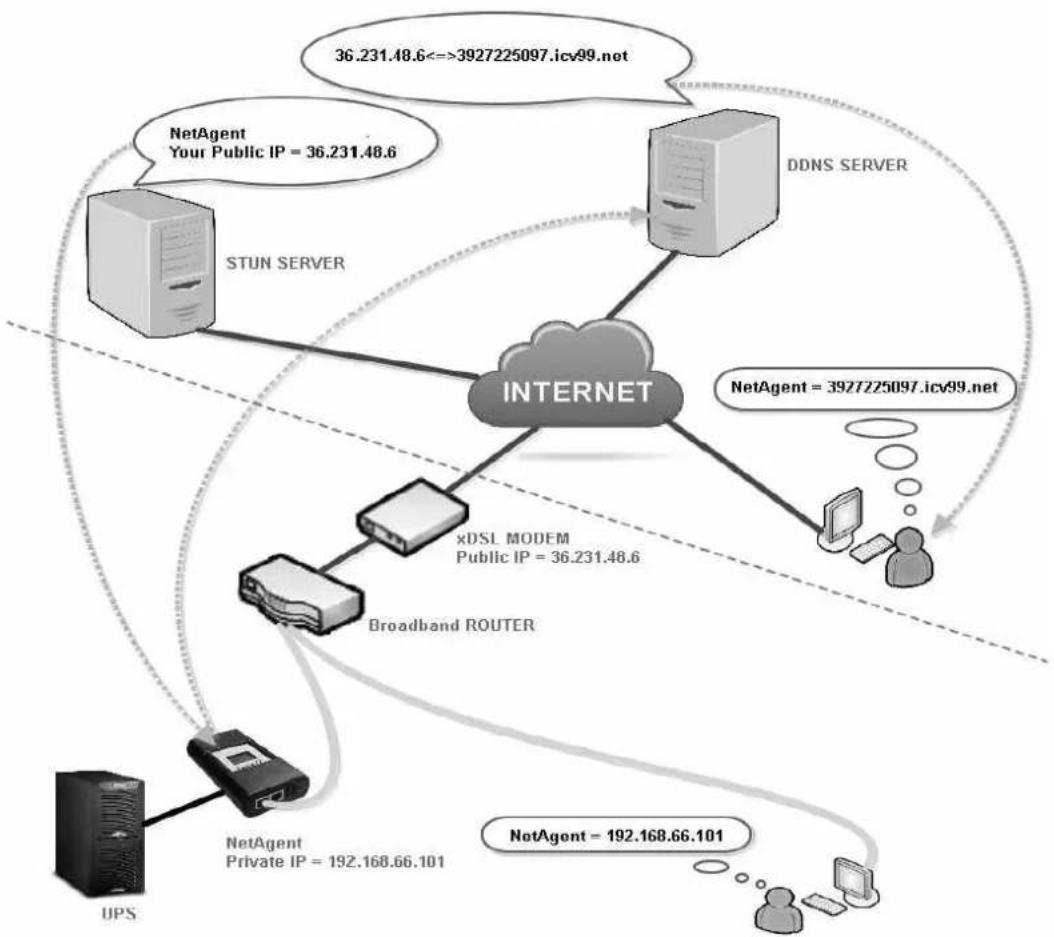
flowchart
graph TD
    A["STUN SERVER"] --> B["INTERNET"]
    C["DDNS SERVER"] --> B
    D["xDSL MODEM\nPublic IP = 36.231.48.6"] --> B
    E["Broadband ROUTER"] --> B
    F["UPS"] --> B
    G["NetAgent\nPrivate IP = 192.168.66.101"] --> B
    H["NetAgent\nYour Public IP = 36.231.48.6"] --> B
    I["NetAgent = 192.168.66.101"] --> B
    J["Internet"] --> B
    K["36.231.48.6<=>3927225097.icv99.net"] --> B
    L["NetAgent = 3927225097.icv99.net"] --> B
If to use iCV99.net as Service Provide which host by Megatec, instruction as below:
- Ensure NetAgent is able to connect to Internet. Select icv99.net from the drop down list of the Service Provider. The Domain Name and Login Name will automatically be fill-in with serial number of the device. Enter the password of the NetAgent which is printed on the NetAgent label, then click Apply.
![NetAgent 9 Mini & NetAgent 9 4. Registration complete Latest Events [07:64:32] Registration width DCNS server completed Configuration > Network IPv4 IPv6 Ethernet Dynamic DNS PPPoE None 3322.org dhs.org DynDNS(Dynamic) DynDNS(Custom) myddns.com zive.org freedns.org icv99.net 1. Select icv99.net 2. Enter password Web/Telnet System Time SMS Modem NetSwitch NetFeeler Modbus Language Log Information Help 3. Click Apply Apply Reset Help NetAgent Mini & NetAgent II http://192.168.66.103/ UPS Agent(My Office) Network IP Address IP Address 192.168.66.103 Subnet Mask 255.255.255.0 Gateway 192.168.66.1 Obtain an IP address* Using DHCP DNS Server IP Primary DNS Server IP 192.168.66.1 Secondary DNS Server IP Ethernet Connection Type* Auto Sense Stop UPS communication when Ethernet disconnected No Modbus on TCP Device ID 1 Dynamic DNS Services Provider icv99.net Domain Name 3926404591.icv99.net Login Name 3926404591 Login Password ********** Use external STUN server to get Public IP to register Yes Primary STUN Server IP 211.21.67.53 Secondary STUN Server IP PPPoE When Connections should be made Disinacted 1 None 3322.org dhs.org DynDNS(Dynamic) DynDNS(Custom) myddns.com zive.org icv99.net NetAgent II® Magic Data Technologies Inc. Tested to Comply with FCS Standards For Home or Office Use CE S/N:T-3926404591 Model:BT506 MAC:00-03-EA-08-2D-EF Password:2BB1ED12 S/N:T-3926404591 Model:BT506 MAC:00-03-EA-08-2D-EF Password:2BB1ED12 3. Click Apply](/content/2026/05/798239/images/bae298ea4b1f4a35e4570d5bf367cc2a7b23632e247401b12c27f37342e9e298.jpg)
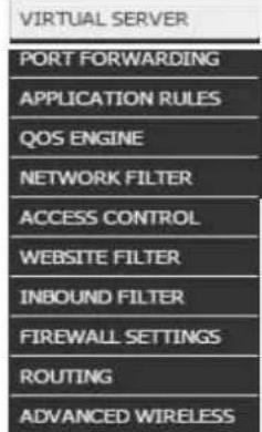
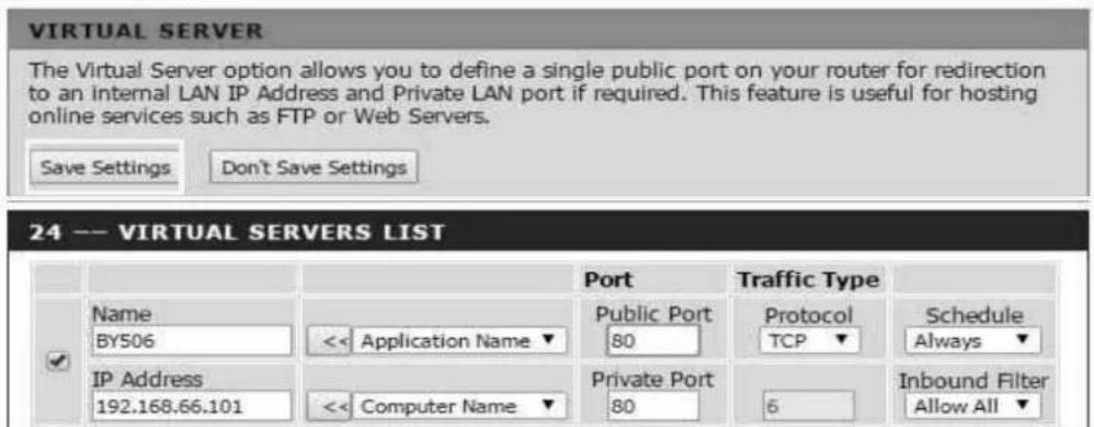
- If using router, please login to router and direct IP and port number under virtual server for port forwarding. Kindly refer to router's manual
Router Configuration
- After 20 minutes, NetAgent should be login with its DDNS Domain name
NetAgent 9 Mini & NetAgent 9
![http://392725097.icv99.net/ UPS Agent(My Office) Latest Events [11:31:01] UPS Load Normal (10%) [11:30:52] UPS Load Overrun (10%) [11:30:40] UPS communication has been established. NetAgent Mini & NetAgent II Information System Status Basic Information Current Status Remote Control Motor/Chart SMS Modem Status AC Status Normal Input Line Voltage 220.1 V Input Max. Line Voltage 220.1 V Input Min. Line Voltage 220.1 V 50.0 Hz NetAgent http://3926404591.icv99.net/ UPS Agent(My Office) NetAgent Current Status Information System Status Basic Information Current Status Remote Control Meter/Chart Modem Status NetFeeler II Configuration Log Information Help Refresh status every 10 seconds ▼ UPS Status UPS Normal Input Status AC Status Normal Input Line Voltage 220.1 V Input Max. Line Voltage 220.1 V Input Min. Line Voltage 220.1 V Input Frequency 50.0 Hz Output Status Output Voltage 220.1 V Output Status Online UPS load 10 % Battery Status Temperature 30.1 °C (86.1 °F ) Battery Status Battery Normal Battery Capacity 100 % Battery Voltage 325.2 V Time on Battery 00:00:00 Estimated Battery Remaining Time 00:00:00 UPS Last Self Test -- UPS Next Self Test Help](/content/2026/05/798239/images/ea3fce003edec7749535c04eb469cc6053d9557f311aba7237284b7b411e0498.jpg)
4. To change domain name or password, please go to www.icv99.net
- PPPoE
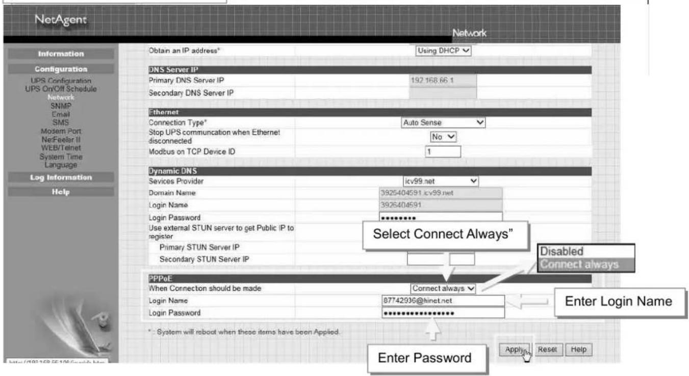
Use this option to allow NetAgent to connect to the Internet directly using your xDSL modem by PPPoE. Enter the Login name and password to enable the connection. Once set-up, NetAgent will connect directly to the Internet, any abnormal connection failure would also cause to re-dial
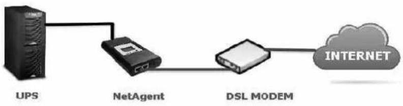
flowchart
graph LR
    UPS --> NetAgent
    NetAgent --> DSLMODEM
    DSLMODEM --> INTERNET
NetAgent 9 Mini & NetAgent 9
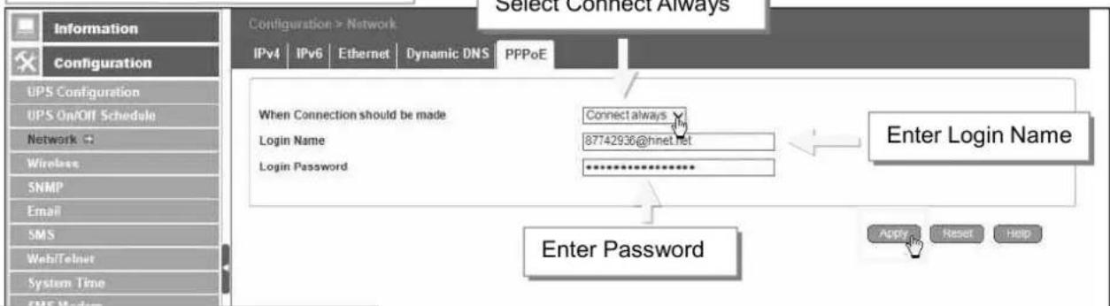
NetAgent Mini & NetAgent II
■ Configuration > Wireless
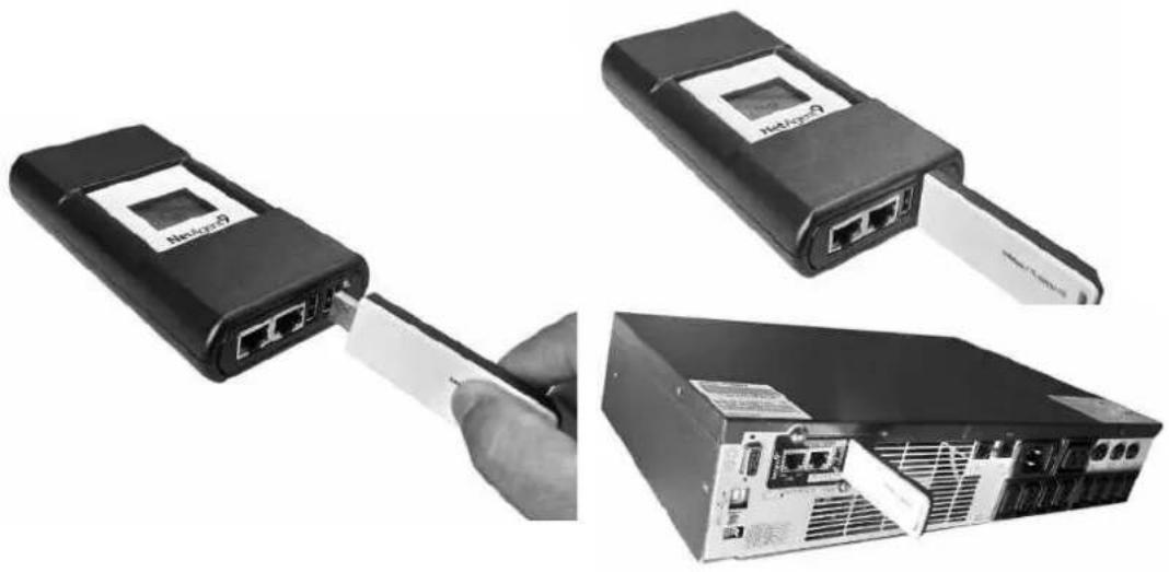
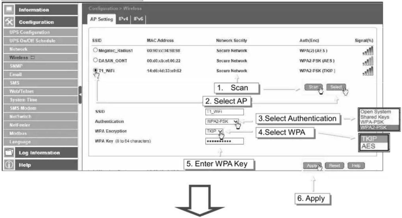
This is to configure Wireless network with USB wireless dongle. This feature only apply to NetAgent 9 model of BX and BY series. (USB wireless dongle is optional) NetAgent 9 BX/BY models supports wireless encryption of Open system; Shared Key; WEP(64 /128 bit) / WPA / WPA2(TKIP/AES)
- Connect the compatible USB wireless dongle to BX/BY NetAgent
natural_image
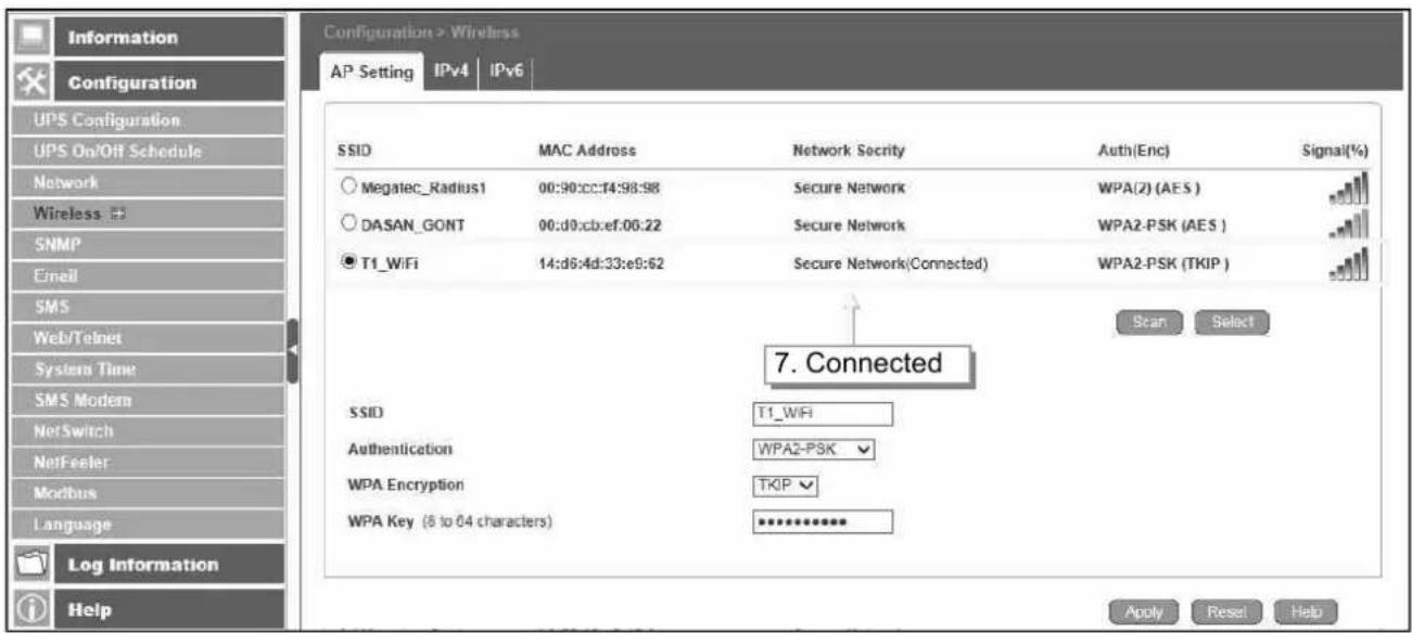
Three black Ethernet devices with network ports being inserted into a compressed rack (no visible text or labels)- Click on【Scan】to search for all the available AP. Select the AP, then enter its SSID, Authentication, WPA Encryption, WPA Key, then click on Apply
NetAgent 9 Mini & NetAgent 9
flowchart
graph TD
    A["Configuration > Wireless"] --> B["AP Setting"]
    B --> C["SSID"]
    C --> D["Megatec_Radius1"]
    C --> E["DASAN_GONT"]
    C --> F["T1_WiFi"]
    D --> G["MAC Address"]
    E --> H["Secure Network"]
    F --> I["Secure Network"]
    G --> J["Network Security"]
    H --> K["Secure Network"]
    I --> L["Secure Network"]
    J --> M["Auth(Enc)"]
    K --> N["Auth(Enc)"]
    L --> O["Auth(Enc)"]
    M --> P["Auth(Enc)"]
    N --> Q["Signal(%)"]
    O --> R["Signal(%)"]
    P --> S["Signal(%)"]
    Q --> T["Scan"]
    R --> U["Select"]
    S --> V["Select AP"]
    T --> W["Select Authentication"]
    U --> X["Select WPA"]
    V --> Y["Open System Shared Keys WPA-PSK WPA2-PSK TKIP AES"]
    W --> Z["WPA2-PSK"]
    X --> AA["WPA2-PSK"]
    Y --> AB["WPA2-PSK"]
    Z --> AC["WPA2-PSK (AES)"]
    AA --> AD["WPA2-PSK (AES)"]
    AB --> AE["WPA2-PSK (TKIP)"]
    AC --> AF["Log Information"]
    AD --> AG["Log Information"]
    AE --> AH["Log Information"]
    AF --> AI["Help"]
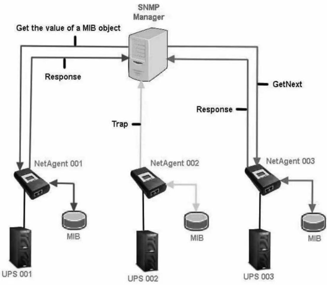
This page is to set NetAgent SNMP settings so it can be used by a NMS (Network Management System). (e.g: SNMPView, it can be available on the NetAgent Utility CD.)
SNMP version supported by NetAgent type
| SNMP V1 | SNMP V2 | SNMP V3 | |
| NetAgent 9 & Mini | √ | √ | √ |
| NetAgent II & Mini | √ | √ |
flowchart
graph TD
    A["SNMP Manager"] -->|Get the value of a MIB object| B["NetAgent 001"]
    A -->|Get the value of a MIB object| C["NetAgent 002"]
    A -->|Get the value of a MIB object| D["NetAgent 003"]
    B --> E["MIB"]
    C --> F["MIB"]
    D --> G["MIB"]
    E --> H["UPS 001"]
    F --> I["UPS 002"]
    G --> J["UPS 003"]
    H --> K["Response"]
    I --> L["Response"]
    J --> M["Response"]
    K --> N["GetNext"]
    L --> N
    M --> N
    N --> O["Trap"]
    style A fill:#f9f,stroke:#333
    style B fill:#ccf,stroke:#333
    style C fill:#ccf,stroke:#333
    style D fill:#ccf,stroke:#333
    style E fill:#dfd,stroke:#333
    style F fill:#dfd,stroke:#333
    style G fill:#dfd,stroke:#333
    style H fill:#dfd,stroke:#333
    style I fill:#dfd,stroke:#333
    style J fill:#dfd,stroke:#333
    style K fill:#dfd,stroke:#333
    style L fill:#dfd,stroke:#333
    style M fill:#dfd,stroke:#333
    style N fill:#dfd,stroke:#333
- General
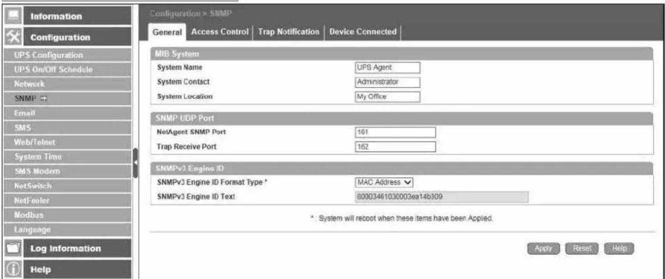
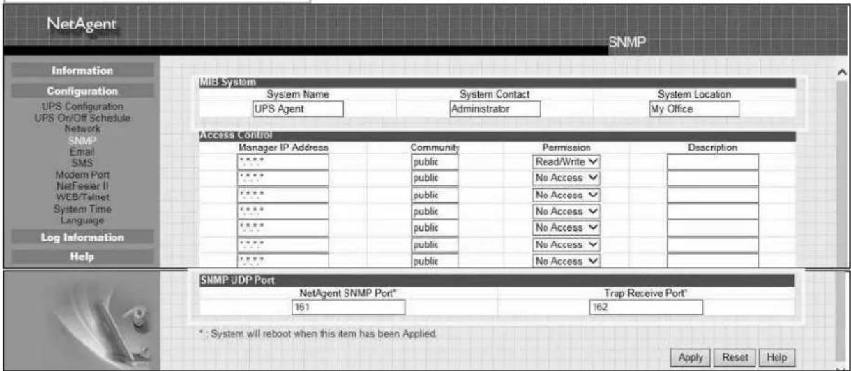
MIB System
System Name
This section is to give a name to the NetAgent.
System Contact
This section is to give a name to the administrator.
System Location
This section is to set NetAgent location.
SNMP UDP Port
The port that NetAgnet receive and send SNMP command. (Default is 161)
Trap Receive Port :
The port to receive trap. (Default is 162)
SNMPv3 Engine ID
SNMPv3 Engine ID Format Type :
When using SNMPv3, NetAgent requires to have its Engine ID for identification to generate authentication and encryption key. Format type can be select from the drop down list with option of MAC Address / IPv4 / IPv6 / Manual
Once click on Apply, NetAgent will reboot
SNMPv3 Engine ID Text :
SNMPv3 Engine ID content
NetAgent 9 Mini & NetAgent 9
NetAgent Mini & NetAgent II
- Access Control
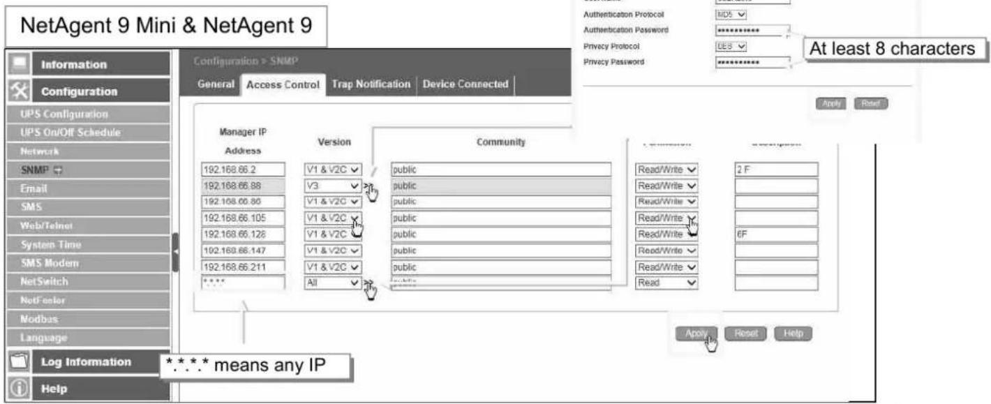
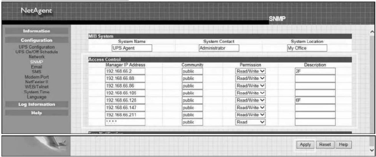
Manager IP Address :
This is to set the IP address that the administrator can manage NetAgent from. It is valid for up to 8 IP addresses. To manage NetAgent from any IP address, enter *.*.*into Manager IP address.
Version:
This is to select between SNMPv1& SNMPv2 or SNMPv3 (SNMPv3 only applies to NetAgent 9 series) When select All and V3, user name, password, authentication and privacy are required
Community :
This section is to set a Community name for NMS. The community name has to be as the same as the setting in NMS. (Default is public)
Permission :
This is to set authorities of administrators. Options are Read, Read/Write, and No Access.
Description :
This is to make note for administrator's reference
NetAgent Mini & NetAgent II
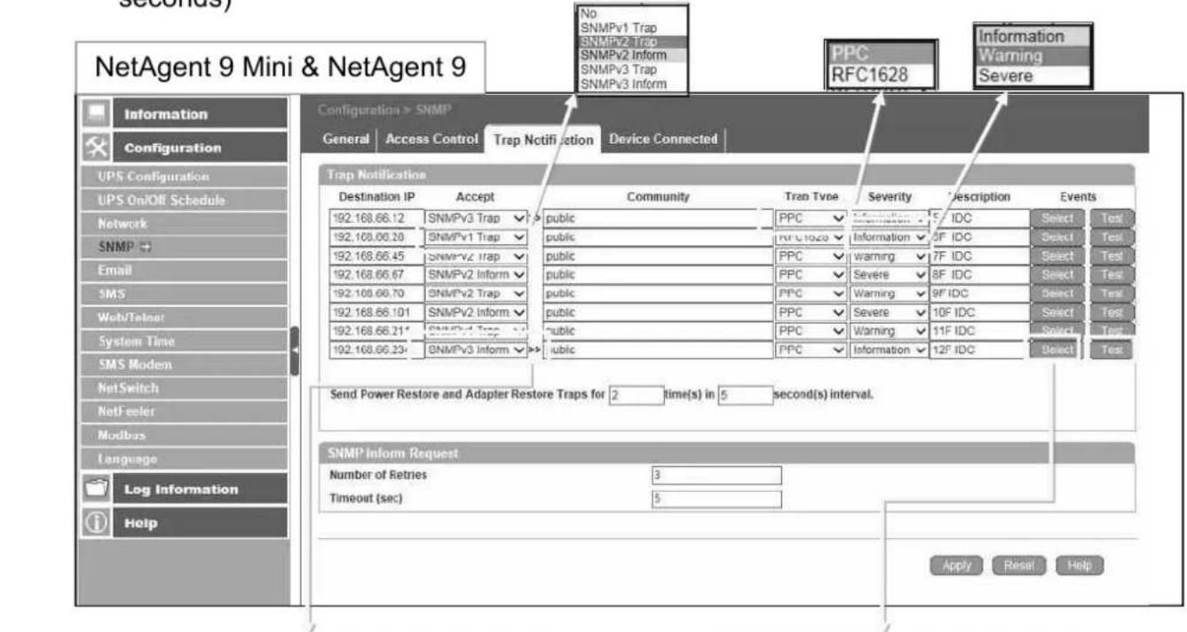
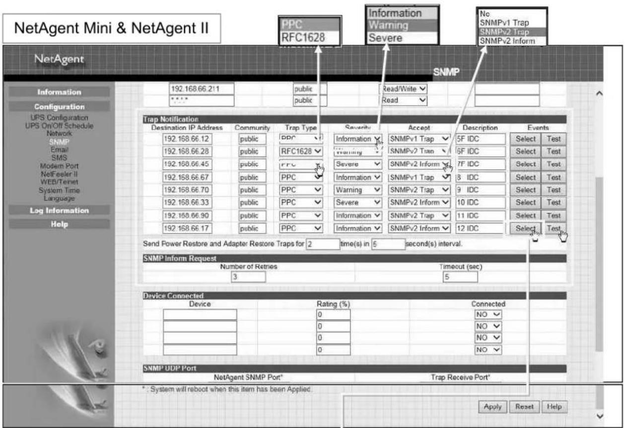
- Trap Notification
Trap Notification
Destination IP Address :
To set receivers IP address for receiving traps sent by NetAgent. It is valid for up to 8 IP Addresses.
Accept :
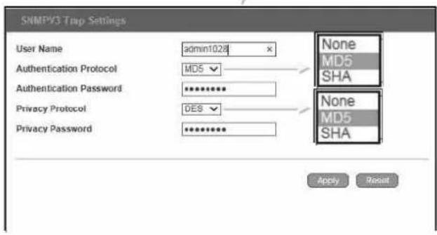
Select the trap type of its SNMP version or Inform from drop down list. When SNMPv3 trap or SNMPv3 Inform is selected, username/password and authentication information are required.
Community :
Trap receiver and NetAgent must be same community. (Default is public)
Trap Type :
Select from PPC MIB or RFC1628 MIB (Default is PPC)
●MIB file is available in the CD provided with NetAgent
Severity :
This section is to set Trap level for each receiver. There are three levels as below
☐ Information: To receive all traps.
□ Warning: To receive only "warning" and "severe" traps.
☐ Severe: To receive only “severe” traps.
(Please refer to NMS manual for Trap levels.)
Description :
This is to make note for administrator's reference
Events :
This is to select events for NetAgent to send traps. Click on Select to show the full Events List. Click on Test to send test trap to ensure all setting is correct
Send Power Restore and Adaptor Restore Traps for X time(s) in X second(s) Interval.
This is to set number of trap to send in preset second when power restore on NetAgent. This is to check if the communication between trap receiver and NetAgent remains well or not after power recovers
SNMP Inform Request
This is to set the number of times that the NetAgent can request a response from the sending Inform host with a preset value. (Default is 3 times and an interval of 5 seconds)
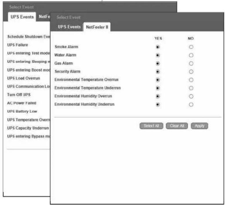
| UPS Events | Yes | No |
| Schedule Shutdown Event | ● | ○ |
| UPS Failure | ● | ○ |
| UPS entering Test mode | ● | ○ |
| UPS entering Sleeping mode | ● | ○ |
| UPS entering Boost mode | ● | ○ |
| UPS Load Overrun | ● | ○ |
| UPS Communication Lost | ● | ○ |
| Turn Off UPS | ● | ○ |
| AC Power Failed | ● | ○ |
| UPS Battery Low | ● | ○ |
| UPS Temperature Overrun | ● | ○ |
| UPS Capacity Underrun | ● | ○ |
| UPS entering Bypass mode | ● | ○ |
| NetFeeler II | Yes | No |
| Smoke Alarm | ● | ○ |
| Water Alarm | ● | ○ |
| Gas Alarm | ● | ○ |
| Security Alarm | ● | ○ |
| Environmental Temperature Overrun | ● | ○ |
| Environmental Temperature Underrun | ● | ○ |
| Environmental Humidity Overrun | ● | ○ |
| Environmental Humidity Underrun | ● | ○ |
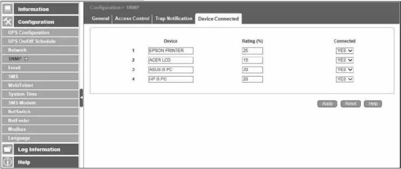
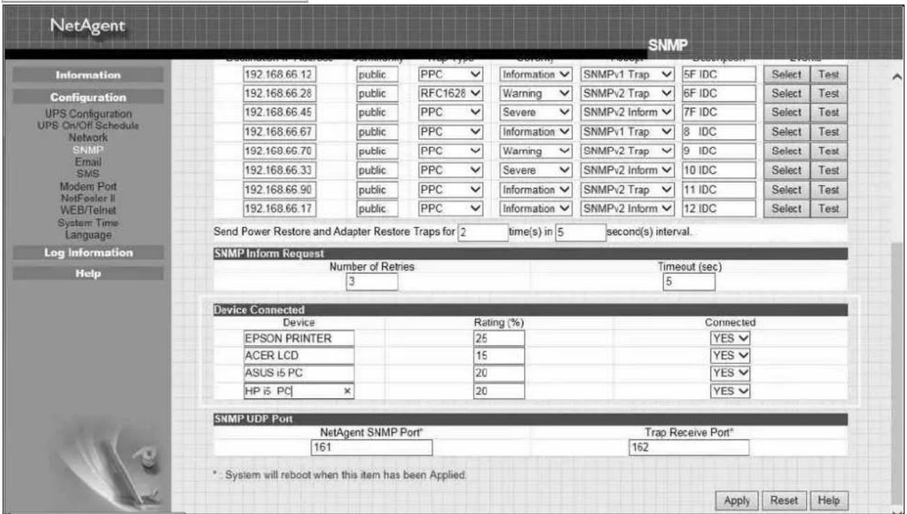
● Device Connected
This section is to set the usage power and connection status of other devices which connects to the same UPS as NetAgent uses.
NetAgent 9 Mini & NetAgent 9
NetAgent Mini & NetAgent II
Configuration > Email
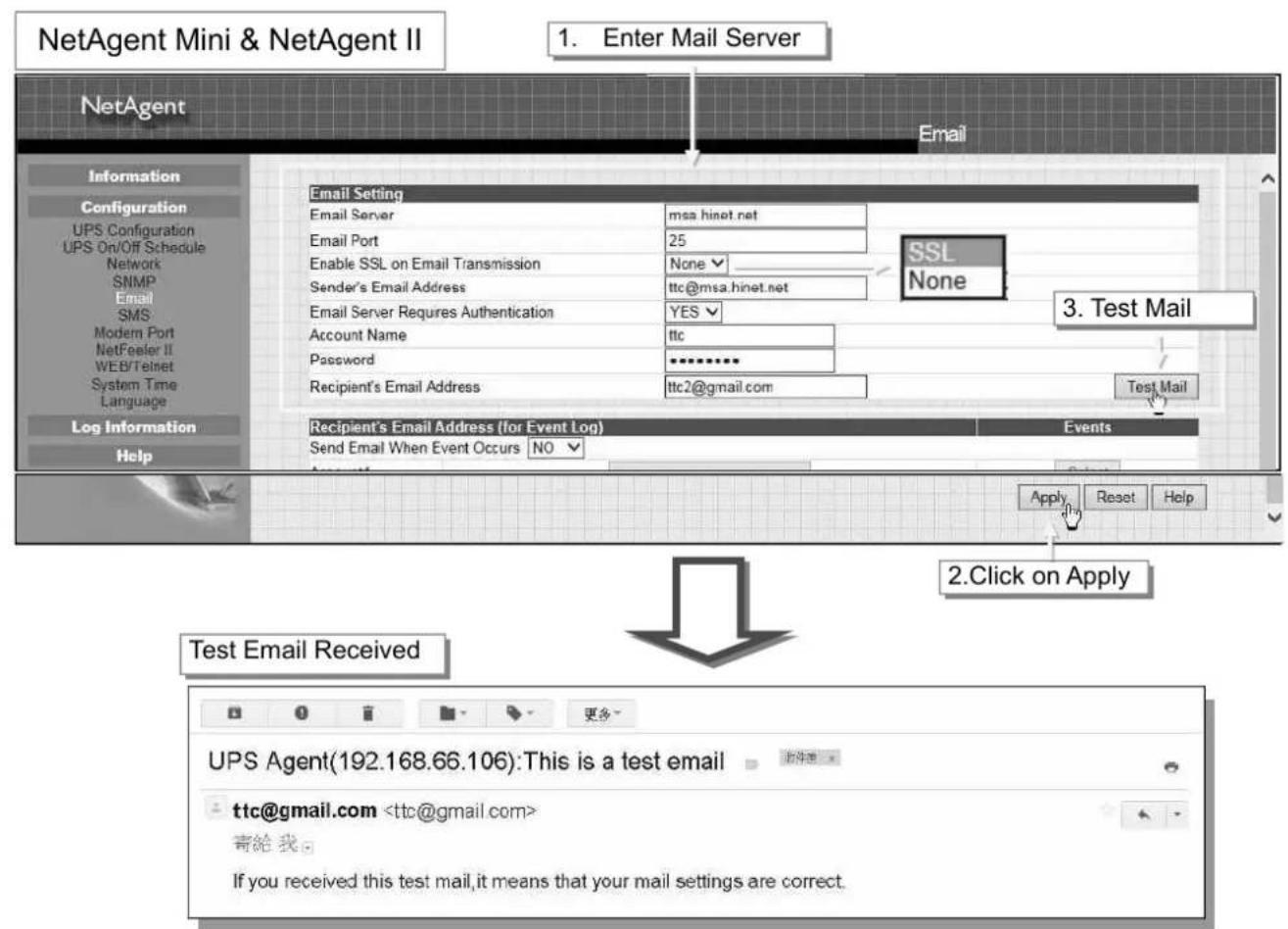
To send email notification when event occurs or data log
- Email Setting
Email Server:
Enter the address of email server
Email Port:
Email Port that use for sending email
Enable SSL on Email Transmission:
Select SSL type for email transmission
Type of encryption that NetAgent model supports
| SSL | TLS | STARTTLS | |
| NetAgent 9 & Mini | √ | √ | √ |
| NetAgent II DT/CT/BT | √ |
Sender's Email Address :
To enter the email address that for sending email
Email Server Requires Authentication :
If such email server requires authentication or not
Account name :
If authentication is required, enter its account name
Password :
If authentication is required, enter its password
Sending Test Mail :
Enter email address to check all configuration is correct or not to receiving mail
NetAgent 9 Mini & NetAgent 9
![Information Configuration UPS Configuration UPS On/OFF Schedule Network SNMP Email → SMS Web/Telnet System Time SMS Modem NetSwitch NetFeeler Modbus Language Configuration > Email Email Setting Email for Event Log Email for Daily Report Email Server smtp.gmail.com Email Port 465 Enable SSL on Email Transmission SSL/TLS Sender's Email Address ttc@gmail.com Email Server Requires Authentication YES Account Name ttc Password ********** Sending test mail Test Mail Apply Reset Help SSL/TLS STARTTLS NONE Information Configuration UPS Configuration UPS On/OFF Schedule Network SNMP Email → SMS Web/Telnet System Time SMS Modem NetSwitch NetFeeler Modbus Language Log Info Help Configuration > Email Email Setting Email for Event Log Email for Daily Report Email Server smtp.gmail.com Email Port 465 Enable SSL on Email Transmission SSL/TLS Sender's Email Address ttc@gmail.com Email Server Requires Authentication YES Account Name ttc Password ********** Sending test mail Test Mail Apply Reset Help NetAgent IX Latest Everas [08:19:86] Mail has been sent Configuration > Email Email Setting Email for Event Log Email for Daily Report Mail Sent Information Configuration UPS Configuration UPS On/OFF Schedule Network SNMP Email → SMS Web/Telnet System Time SMS Modem NetSwitch NetFeeler Modbus Language Log Information Test Email Received UPS Agent(192.168.66.106):This is a test email ttc@gmail.com 寄给我。 If you received this test mail, it means that your mail settings are correct.](/content/2026/05/798239/images/6b3a33d31899ee2edb3452592c666526c3213332b027953d1d62c538ec88b1e3.jpg)
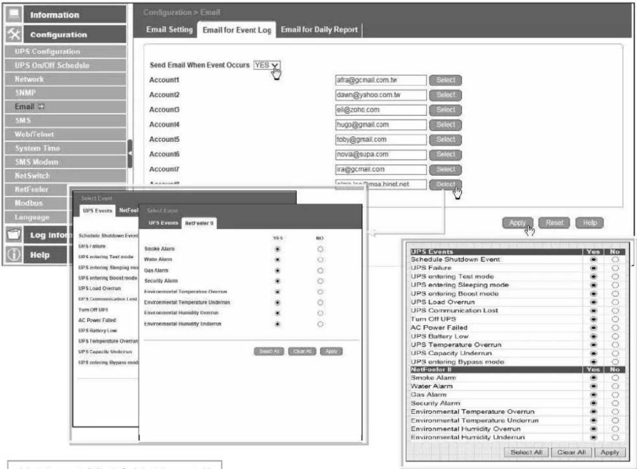
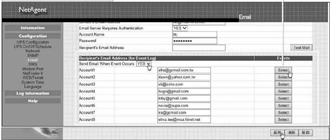
- Email for Event Log (To receive email notification)
To set email addresses to receive warning email sent by NetAgent when selected event occurs. It is valid for up to 8 Email addresses.
NetAgent 9 Mini & NetAgent 9
NetAgent Mini & NetAgent II
● Email for Daily Report (To receive daily report)
This section is to set Email Addresses to receive NetAgent's Daily Report at preset time. It is valid for up to 4 Email addresses. Daily report with content of event and data log.
With NetAgent series, option is available if to send email when event or data log overflows to 500 logs
NetAgent 9 Mini & NetAgent 9
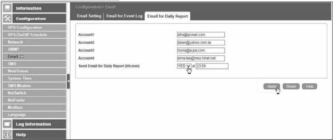
NetAgent Mini & NetAgent II
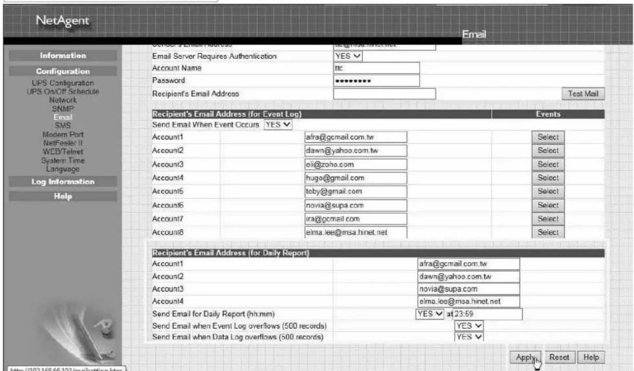
■ Configuration > SMS
When UPS events occurs, it allows Short Message Signals ("SMS") to be sent and received using a GSM/GPRS/CDMA Modem. Operation information are as below for single and three ports of NetAgent.
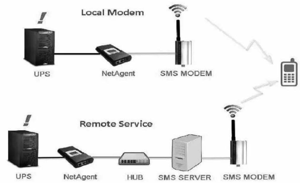
flowchart
graph LR
    subgraph Local Modem
        UPS1["UPS"] --> NetAgent1["NetAgent"]
        NetAgent1 --> SMSMODEM1["SMS MODEM"]
        SMSMODEM1 --> Phone((Phone))
    end
    subgraph Remote Service
        UPS2["UPS"] --> NetAgent2["NetAgent"]
        NetAgent2 --> HUB["HUB"]
        HUB --> SMS_SERVER["SMS SERVER"]
        SMS_SERVER --> SMSMODEM2["SMS MODEM"]
    end
    Local Modem --> Phone
    Remote Service --> Phone
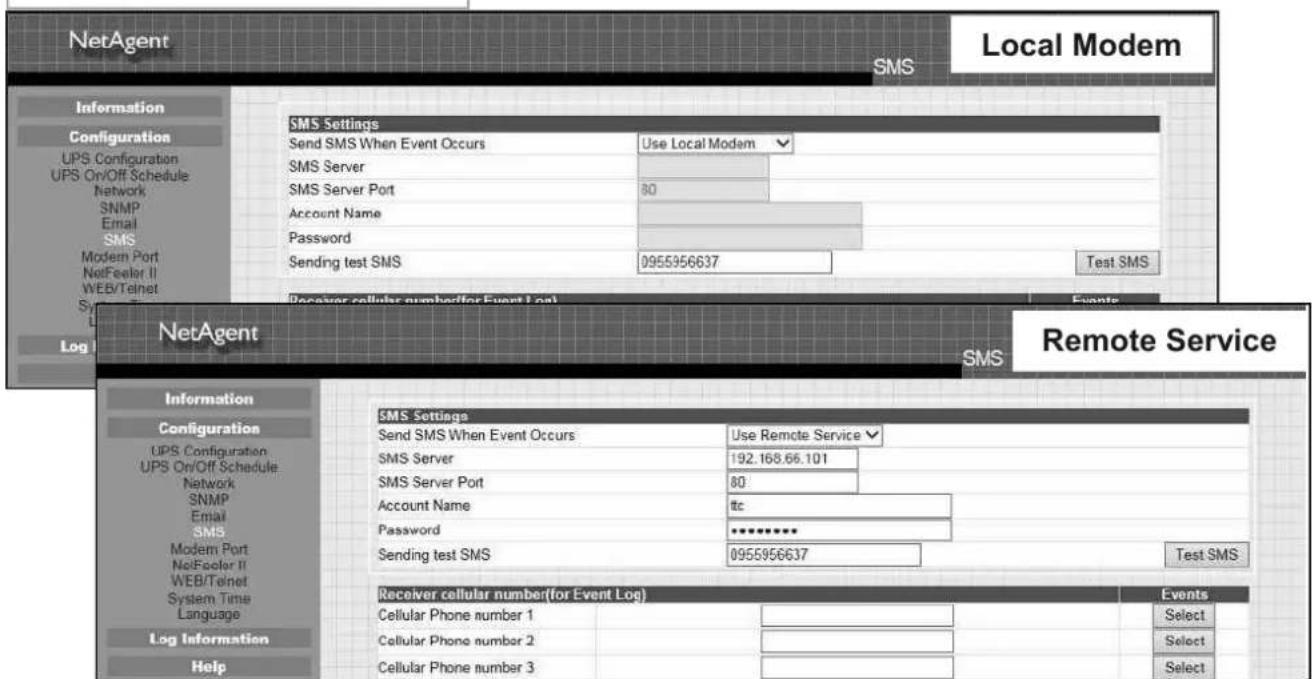
- SMS Setting :
Send SMS When Event Occurs:
☐ Use Local Modem : When GSM modem is connected to NetAgent directly (Refer to SMS Modem section for its installation)
□ Use Remote Service : When GSM modem connects to PC with SMS Server software installed
(Refer to SMS Server section for SMS Server Software installation)
SMS Server :
If select to use Remote Service to send SMS, then enter the IP address of the SMS Server. (The PC that installed SMS Server Software)
SMS Port :
If select to use Remote Service to send SMS, enter the port number that SMS Server uses for sending SMS. (Port 80 is default)
Account Name :
If select to use Remote Service to send SMS, enter SMS Server's account name if required
Password :
If select to use Remote Service to send SMS, enter SMS Server's password if required
Sending test SMS :
When modem and configuration are ready, enter a mobile number to receive testing SMS
NetAgent 9 Mini & NetAgent 9
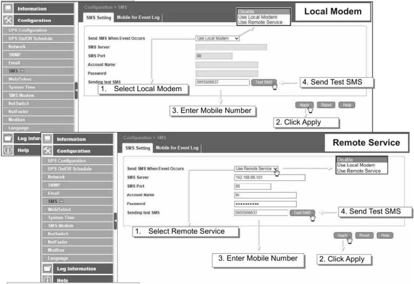
flowchart
graph TD
    A["Configuration > SMS"] --> B["Send SMS When Event Occurs"]
    B --> C["Use Local Modem"]
    C --> D["Local Modem"]
    D --> E["3. Enter Mobile Number"]
    E --> F["4. Send Test SMS"]
    F --> G["Apply Reset Help"]
    H["Log Information"] --> I["Information"]
    I --> J["Configuration"]
    J --> K["Log Infor"]
    K --> L["Help"]
    M["Remote Service"] --> N["1. Select Remote Service"]
    N --> O["3. Enter Mobile Number"]
    O --> P["2. Click Apply"]
    Q["Send SMS When Event Occurs"] --> R["Use Remote Service"]
    S["SMS Server"] --> T["192.168.66.101"]
    U["SMS Port"] --> V["80"]
    W["Account Name"] --> X["<<"]
    Y["Password"] --> Z["**********"]
    AA["Sending test SMS"] --> AB["0955956637"]
    AC["Test SMS"] --> AD["Test SMS"]
    AE["Disable Use Local Modem Use Remote Service"] --> AF["4. Send Test SMS"]
    AG["Apply Reset Help"] --> AH["2. Click Apply"]
NetAgent Mini & NetAgent II
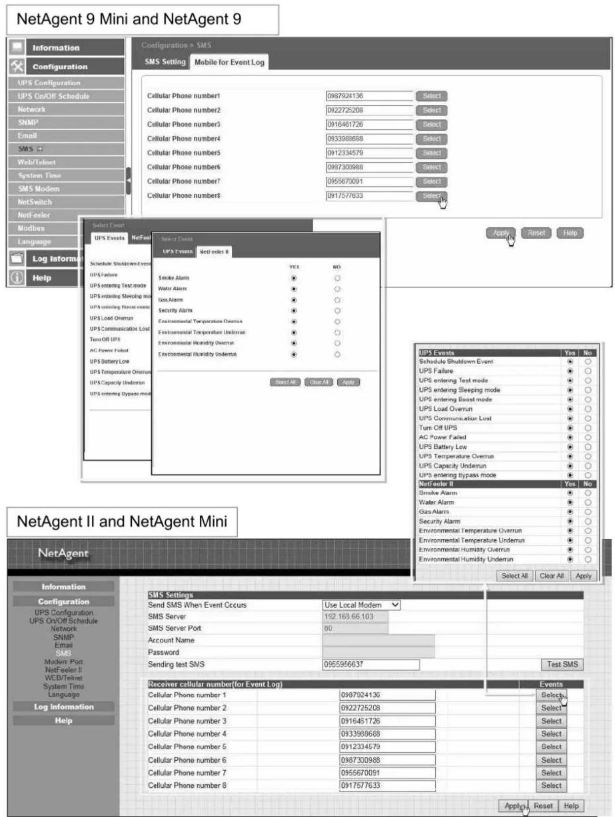
- Mobile for Event Log
To set the recipient's mobile number for SMS notification when event or NetFeeler event occurs. A total of 8 mobile numbers can be assign.
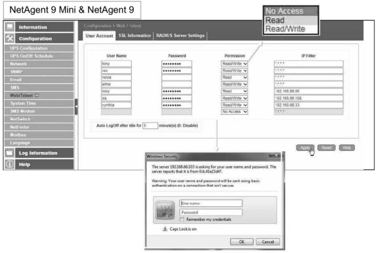
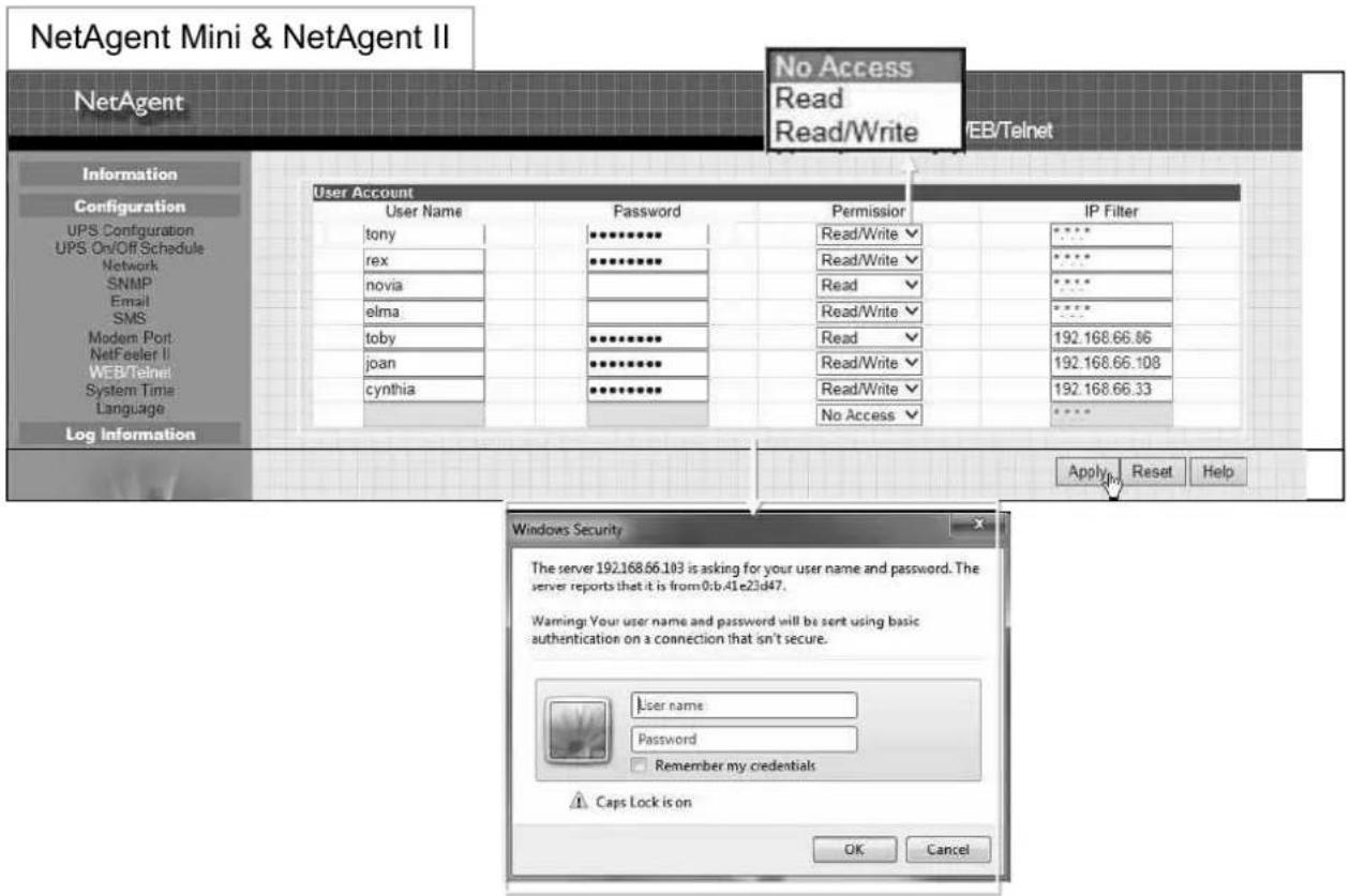
■ Configuration > Web/Telnet
To set permission for each user account for Web and Telnet access. It is valid for up to 8 users.
- User account
User Name :
To set password for NetAgent Web and Telnet access.
Password :
To set password for NetAgent Web and Telnet access.
Permission :
To set No Access / Read/ Read&Write)
- Permission Rule : At least one user account must be Read/Write
- Permission Rule : User name with Read and Write cannot be blank
IP Filter :
Only specific IP address could login to NetAgent
* *.*.* means any IP address
Auto Logoff after Idle for □ minute (s). (0 is disabled)
NetAgent webpage will be logoff automatically if it idle for the preset value.
- SSL Information
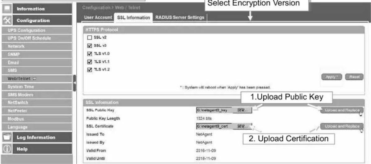
NetAgent supports HTTPS protocol and varies SSL encryptions version for network connection. User may upload its Public Key and Certification for authentication
Table of SSL versions that NetAgent supports
| SSL v2 | SSL v3 | TLS v1.0 | TLS v1.1 | TLS v1.2 | |
| NetAgent9 & Mini | √ | √ | √ | √ | √ |
| NetAgent DT/CT/BT | √ |
HTTPS Protocols
Select the encryption version
□ SSL v2
□ SSL v3
□ SSL v1.0
□ SSL v1.1
□ SSL v1.2
Once click on Apply, NetAgent will reboot
SSL Information
This is to upload the SSL certificate. When both public key and certificate are uploaded to NetAgent web server, the communication will be encrypted by SSL
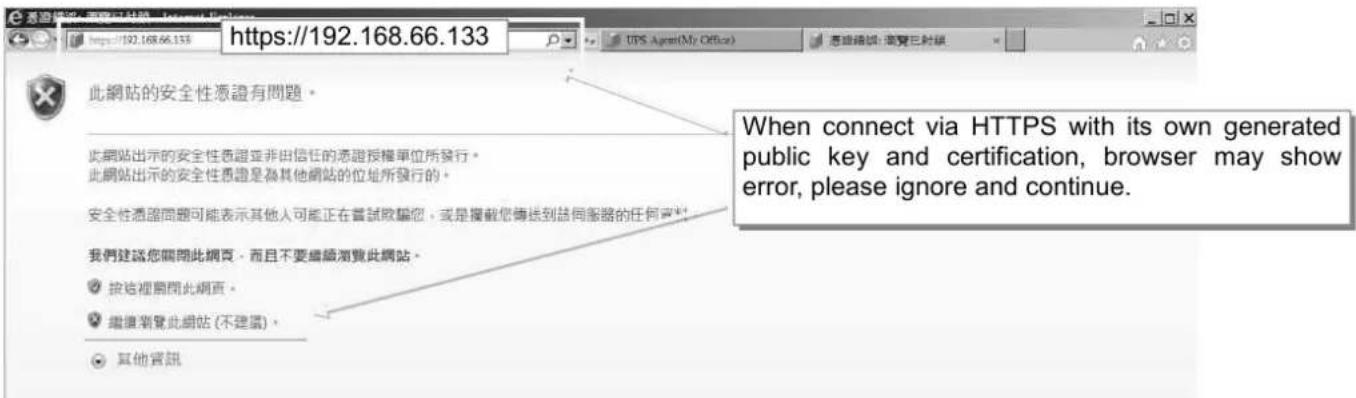
(To communicate via Https, make sure to enable Https port 443.) To create its own public key and certification, please refer to OpenSSL software in the CD
NetAgent 9 Mini & NetAgent 9
NetAgent Mini & NetAgent II
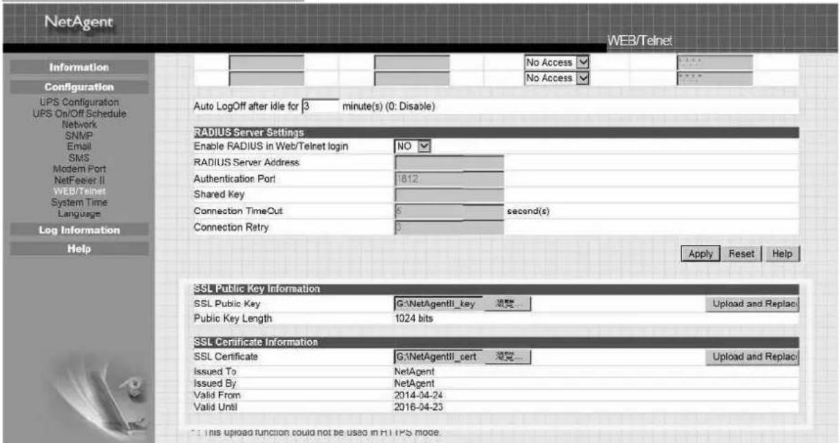
If RADIUS server authentication is required for the network, NetAgent could be added by entering following parameter.
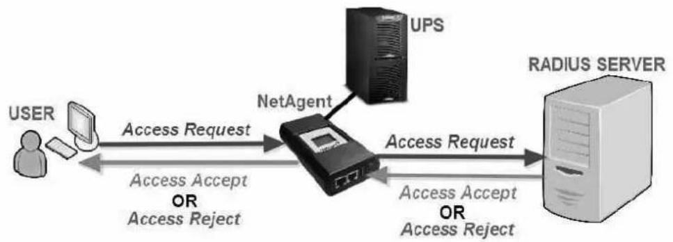
flowchart
graph LR
    A["USER"] -->|Access Request| B["NetAgent"]
    B -->|Access Request| C["RADIUS SERVER"]
    B -->|Access Accept OR Access Reject| A
    B -->|Access Accept OR Access Reject| C
    B --> D["UPS"]
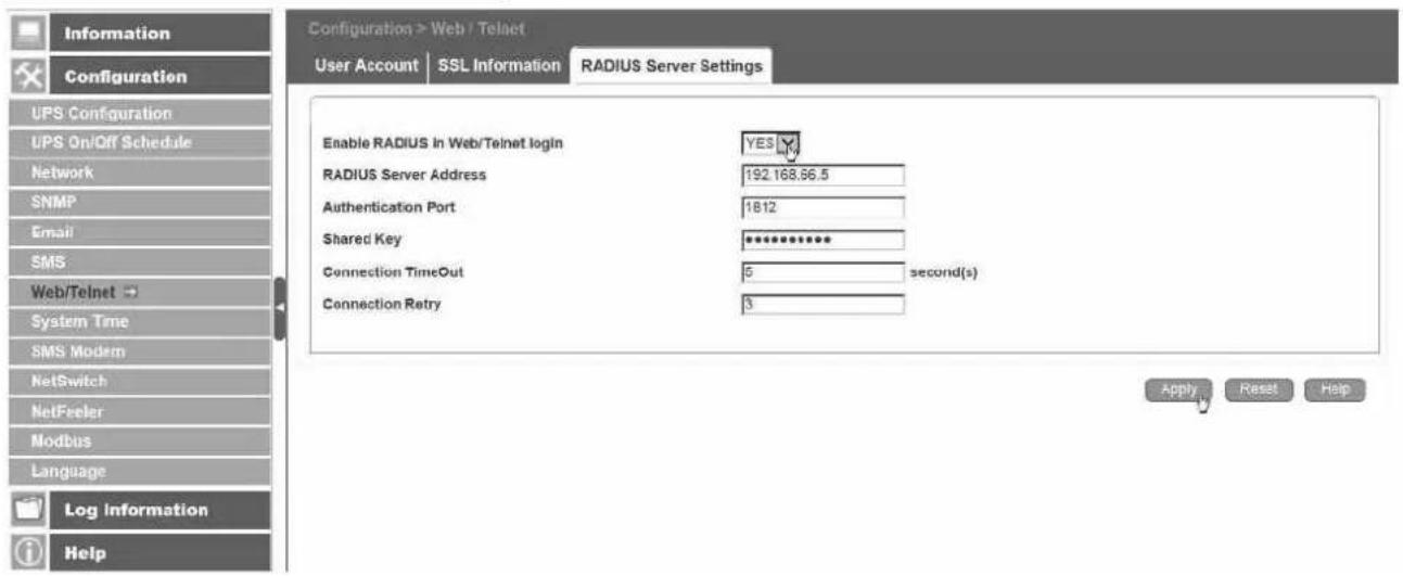
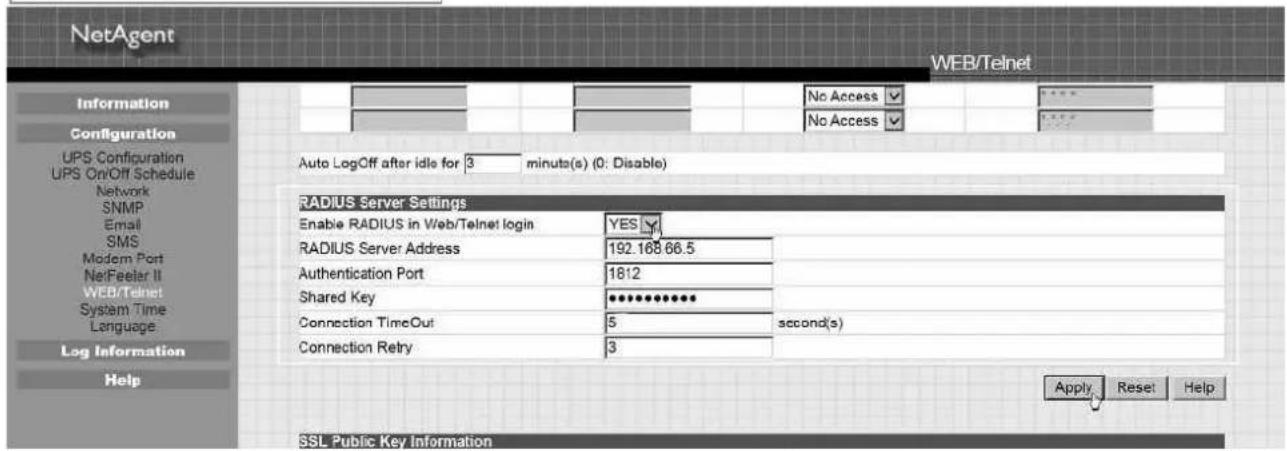
Enable RADIUS in Web/Telnet Login:
To select if to enable RADIUS
RADIUS Server Address :
To enter the IP address of the RADIUS Server
Authentication Port :
RADIUS port number (Default is 812)
Shared Key :
Enter the Shared Key between RADIUS Server and client
Connection Timeout :
Set the number of seconds to suspend the login time after the RADIUS server is rejected
Connection Retry :
Sets the number of connections to the RADIUS server again
NetAgent 9 Mini & NetAgent 9
NetAgent Mini & NetAgent II
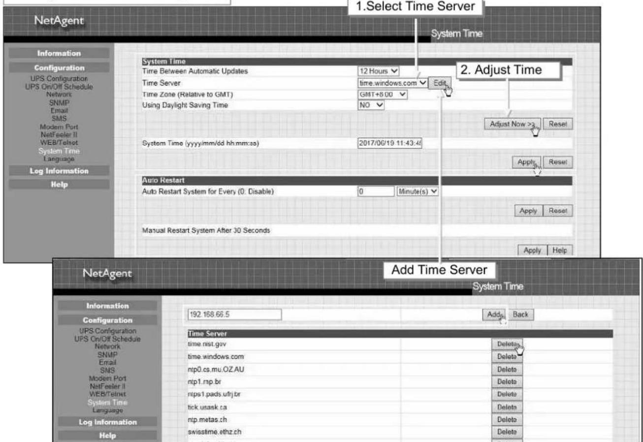
■ Configuration > System Time
This page is to set NetAgent's system time. NetAgent could synchronize with external or internal Time Server.
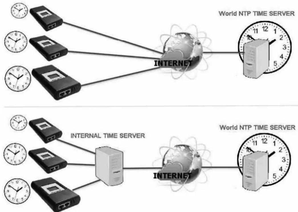
flowchart
graph TD
    subgraph Internet
        A["Device 1"] --> B["Internet"]
        C["Device 2"] --> B
        D["Device 3"] --> B
        E["Device 4"] --> B
        F["Device 5"] --> B
    end
    B --> G["World NTP TIME SERVER"]
    style Internet fill:#f9f,stroke:#333
    style Internet_Pink fill:#ccf,stroke:#333
    style Internet_Pink_Pink fill:#cfc,stroke:#333
    note1["INTERNAL TIME SERVER"]
    note2["INTERNET"]
    note3["World NTP TIME SERVER"]
System Time
Time Between Automatic Updates :
To set an interval for time synchronization.
Time Server :
Time server can be select from the drop down list, or add other time server manually.
Time Zone(Relative to GMT) :
To select its GMT time zone
Using Daylight Saving Time :
Select whether to use the daylight saving time system to adjust the clock for 1 hour in advanced
System Time(yyyy/mm/dd hh:mmm:ss) :
To display the current system time/date of NetAgent. Or click on Adjust Now to adjust to the correct time/date automatically
Restart
Auto Restart System for Every (0 is disabled):
NetAgent to restart automatically at preset hour or minute
Manual Restart System After 30 seconds :
Once click on Apply, NetAgent would restart after 30 seconds
NetAgent 9 Mini & NetAgent 9
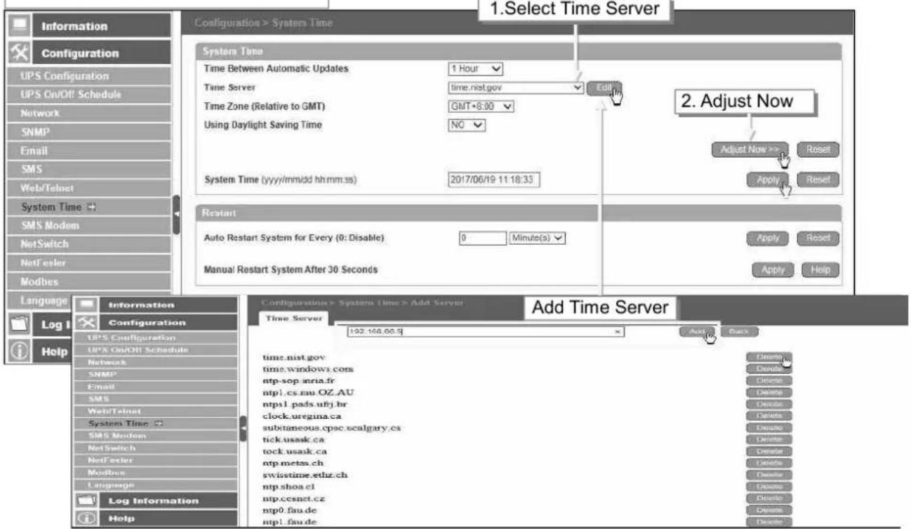
NetAgent 9 Mini & NetAgent 9
■ Configuration > SMS Modem
□ Modem Setup Procedure
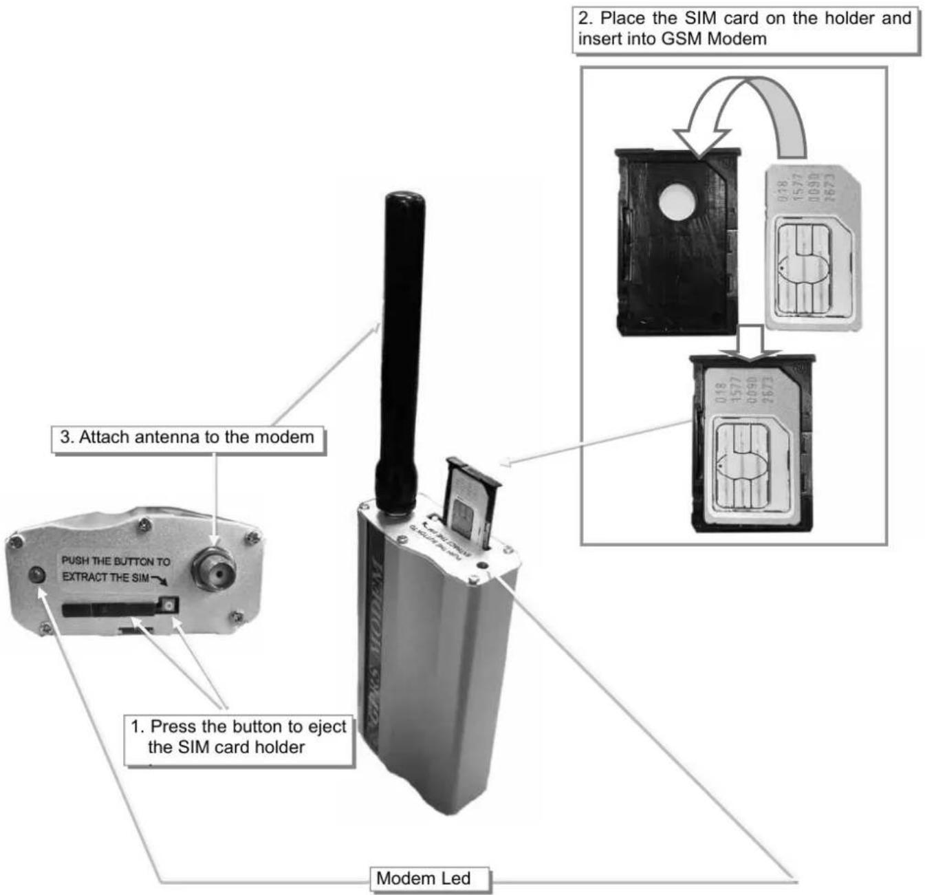
Modem Led Status
- If flash every 0.8 seconds :
■Modem initializing, please wait
■If no respond
(1) Check if PIN is correctly entered, or if PIN is required
(2) Check if SIM card is inserted corrected
(3) Check if no or low signal
- If flash every 3 seconds :
■Modem is ready for operation
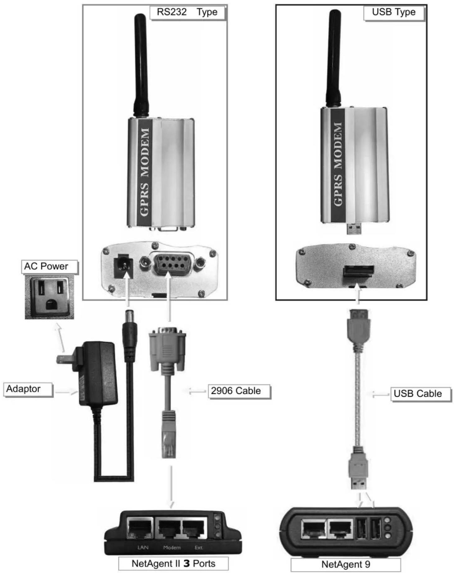
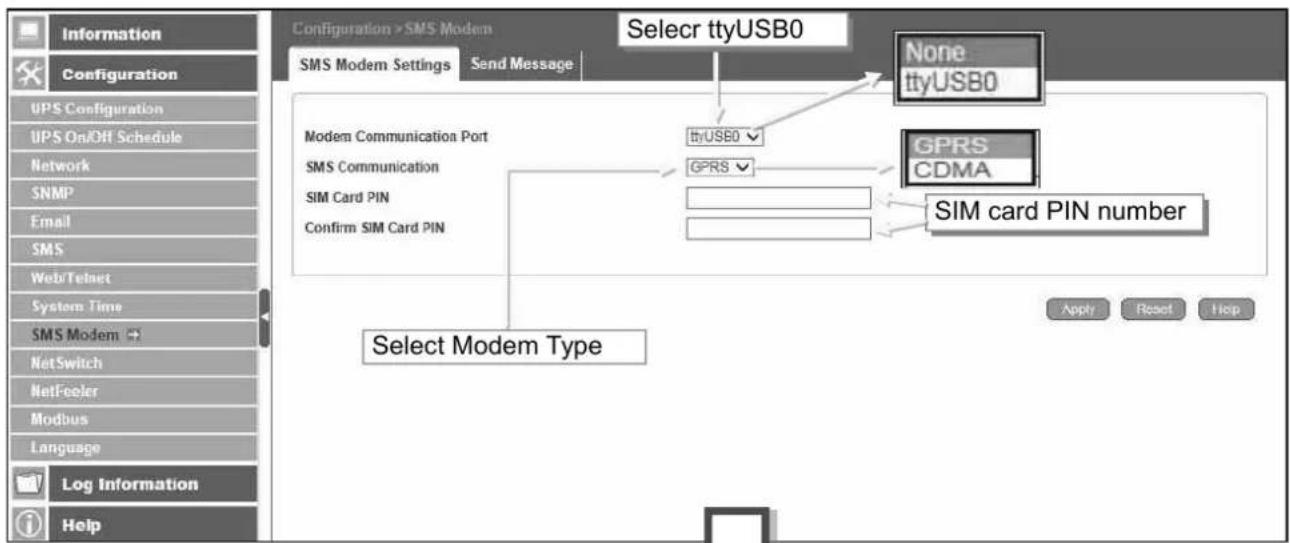
- SMS Modem Settings
Modem Communication Port :
Select "ttyUSB0" for USB modem connects with NetAgent 9 directly ;
Select "SMS " for modem connects with NetAgent II 3 Ports
SMS Communication :
Select between GPRS or CDMA
SIM Card PIN :
If PIN is required for the SIM card, please enter
Confirm SIM PIN :
Retype SIM card PIN
When all done, click on Apply. Modem Information and Status can be check from Information> SMS Modem Status
Once click on Apply on NetAgent 3 ports model, NetAgent will reboot
NetAgent 9 W/USB
- Send Message
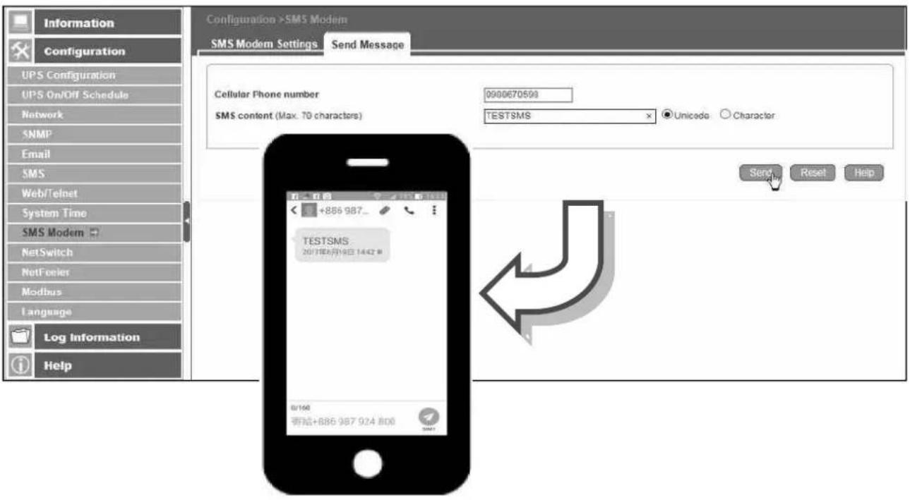
Cellular Phone number :
Enter mobile number
SMS Content(Max.70 Characters):
Enter the SMS content text and select coding. Unicode or Character
![NetAgent II 3 Ports Select SMS] Select Modem Type Modem Port Information Configuration UPS Configuration UPS On/Off Schedule Network SNMP Email SMS Modem Port NetFeder II WEB/Telnet System Time Language Log Information Help Modem Settings Modem Communication Type* SMS Settings SMS Communication SIM Card PIN Confirm SIM Card PIN GPRS CDMA SIM card PIN number Apply Reset Help Receiver cellular number and message content Cellular Phone number 09886705898 SMS content TESTSMS Unicode Character Send Reset Help Enter the mobile number and SMS content, then click on Send](/content/2026/05/798239/images/ebdf60c898860e815c88ab9f11fdd829a1a37362e206dda038c8e0bc43750360.jpg)
■ Configuration > NetSwitch
NetAgent 3 Ports (BT model) or NetAgent 9 (BX/BY model) can also connect with our NetSwitch for remote power management
□ NetSwitch Installation
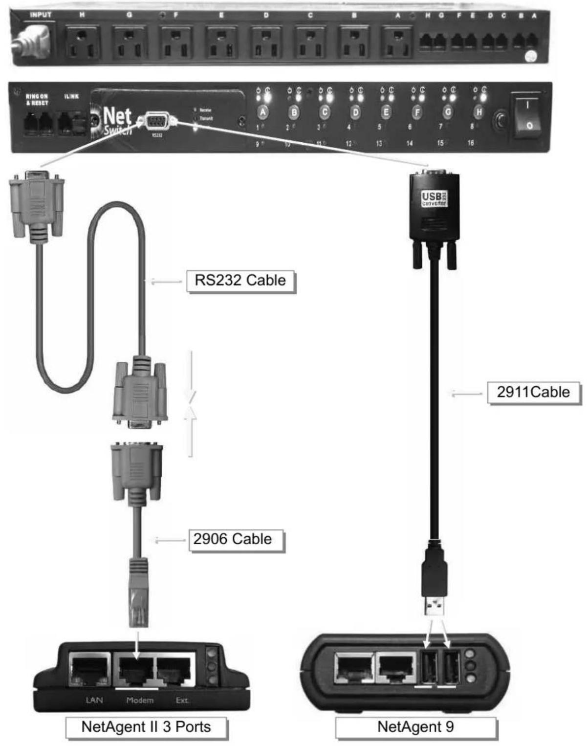
NetSwitch
When NetAgent BT/BX/BY connects with NetSwitch, it able to perform action to the specific outlet when event or alarm triggers
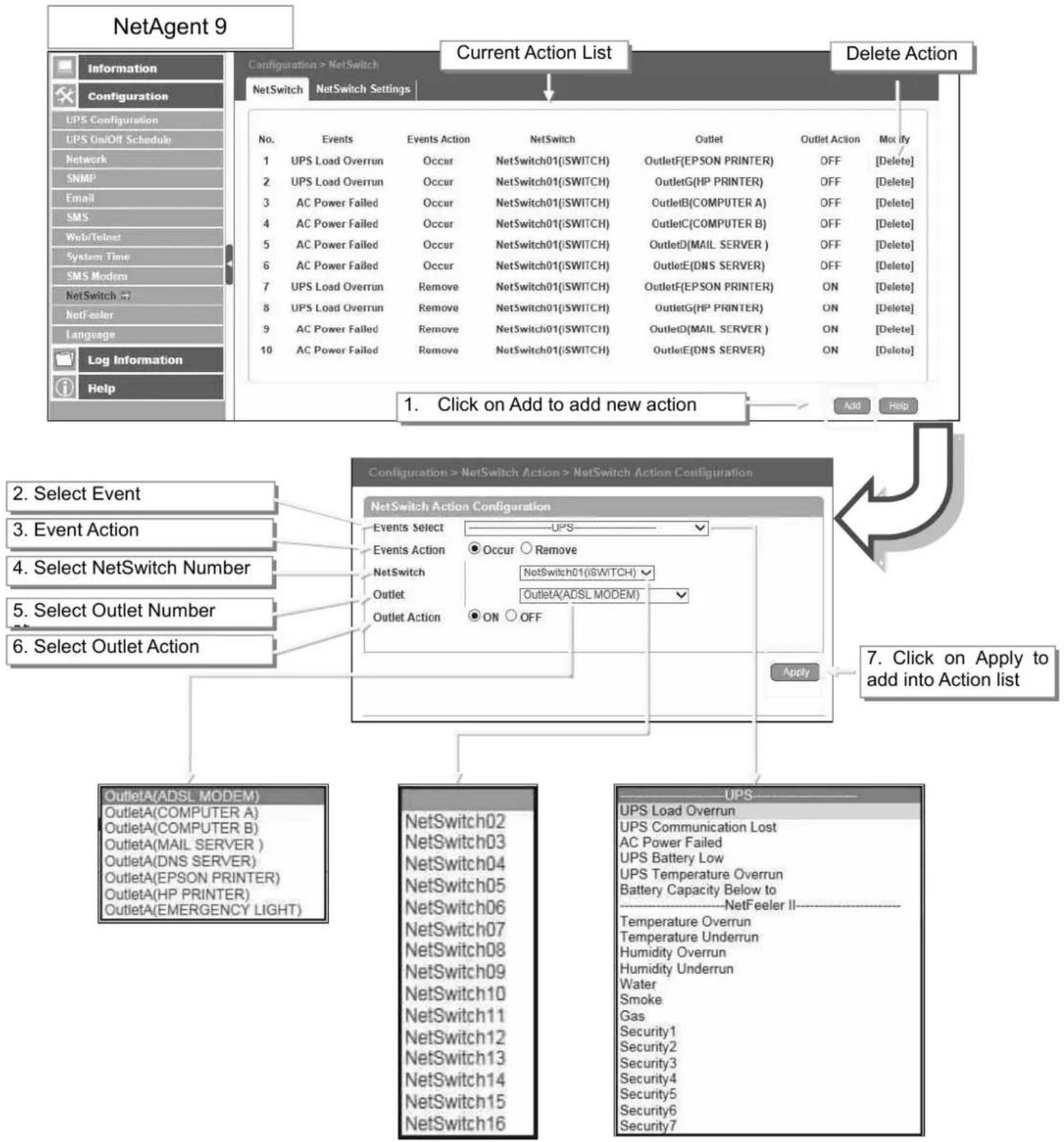
flowchart
graph TD
    A["Configuration > NetSwitch"] --> B["Current Action List"]
    B --> C["Delete Action"]
    D["Configuration > NetSwitch"] --> E["Configuration > NetSwitch Action > NetSwitch Action Configuration"]
    E --> F["Add"]
    E --> G["Help"]

    subgraph_A["Configuration > NetSwitch"]
        H["Information"] --> I["Configuration"]
        J["Configuration"] --> K["LIPS Configuration"]
        L["UPS On/Off Schedule"] --> M["Network"]
        N["SNMP"] --> O["Email"]
        P["EMS"] --> Q["Web/Telnet"]
        R["System Time"] --> S["SMS Modem"]
        T["NetSwitch"] --> U["NetFeeler"]
        V["Language"] --> W["Log Information"]
        X["Help"]

    end

    subgraph_B["Current Action List"]
        Y["No. Events Events Action NetSwitch Outlet Outlet Action Modify"] --> Z["1 UPS Load Overrun Occur NetSwitch01(iSWITCH) OutletF(EPSON PRINTER) OFF [Delete"]]
        Y --> AA["2 UPS Load Overrun Occur NetSwitch01(iSWITCH) OutletG(HP PRINTER) OFF [Delete"]]
        Y --> AB["3 AC Power Failed Occur NetSwitch01(iSWITCH) OutletB(COMPUTER A) OFF [Delete"]]
        Y --> AC["4 AC Power Failed Occur NetSwitch01(iSWITCH) OutletC(COMPUTER B) OFF [Delete"]]
        Y --> AD["5 AC Power Failed Occur NetSwitch01(iSWITCH) OutletD(MAIL SERVER) OFF [Delete"]]
        Y --> AE["6 AC Power Failed Occur NetSwitch01(iSWITCH) OutletE(DNS SERVER) OFF [Delete"]]
        Y --> AF["7 UPS Load Overrun Remove NetSwitch01(iSWITCH) OutletF(EPSON PRINTER) ON [Delete"]]
        Y --> AG["8 UPS Load Overrun Remove NetSwitch01(iSWITCH) OutletG(HP PRINTER) ON [Delete"]]
        Y --> AH["9 AC Power Failed Remove NetSwitch01(iSWITCH) OutletD(MAIL SERVER) ON [Delete"]]
        Y --> AI["10 AC Power Failed Remove NetSwitch01(iSWITCH) OutletE(DNS SERVER) ON [Delete"]]
    end

    subgraph_C["Delete Action"]
        J --> J1["Add"]
        J --> J2["Help"]

    subgraph_E["Configuration > NetSwitch Action > NetSwitch Action Configuration"]
        E --> K["Configuration > NetSwitch Action > NetSwitch Action Configuration"]
        K --> L["Add"]
    end

    subgraph_F["Configuration > NetSwitch Action"]
        K --> M["Configuration > NetSwitch Action Configuration"]
        M --> N["Events Select UPS Event Action Occur Remove"]
        M --> O["NetSwitch Outlet OutletAction OutletA(ADSL MODEM) ON OFF"]
    end

    subgraph_G["Configuration > NetSwitch Action"]
        M --> P["Configuration > NetSwitch Action"]
        P --> Q["Apply"]
    end

    subgraph_H["Configuration > NetSwitch Action"]
        M --> R["Configuration > NetSwitch Action"]
        R --> S["Apply"]
    end

    subgraph_I["Configuration > NetSwitch Action"]
        M --> T["Configuration > NetSwitch Action"]
        T --> U["Apply"]
    end

    subgraph J
        J --> J1["Select Event"]
        J --> J2["Event Action"]
        J --> J3["Select NetSwitch Number"]
        J --> J4["Select Outlet Number"]
        J --> J5["Select Outlet Action"]
    end

    subgraph K
        K --> K1["OutletA(ADSL MODEM)"]
        K --> K2["OutletA(COMPUTER A)"]
        K --> K3["OutletA(COMPUTER B)"]
        K --> K4["OutletA(MAIL SERVER)"]
        K --> K5["OutletA(DNS SERVER)"]
        K --> K6["OutletA(EPSON PRINTER)"]
        K --> K7["OutletA(HP PRINTER)"]
        K --> K8["OutletA(EMERGENCY LIGHT)"]
    end

    subgraph L
        L --> L1["NetSwitch02"]
        L --> L2["NetSwitch03"]
        L --> L3["NetSwitch04"]
        L --> L4["NetSwitch05"]
        L --> L5["NetSwitch06"]
        L --> L6["NetSwitch07"]
        L --> L7["NetSwitch08"]
        L --> L8["NetSwitch09"]
        L --> L9["NetSwitch10"]
        L --> L10["NetSwitch11"]
        L --> L11["NetSwitch12"]
        L --> L12["NetSwitch13"]
        L --> L13["NetSwitch14"]
        L --> L14["NetSwitch15"]
        L --> L15["NetSwitch16"]
    end

    subgraph M
        M --> M1[UPS Load Overrun UPS Communication Lost AC Power Failed UPS Battery Low UPS Temperature Overrun Battery Capacity Below to NetFeeler II Temperature Overrun Temperature Underrun Humidity Overrun Humidity Underrun Water Smoke Gas Security1 Security2 Security3 Security4 Security5 Security6 Security7
    end
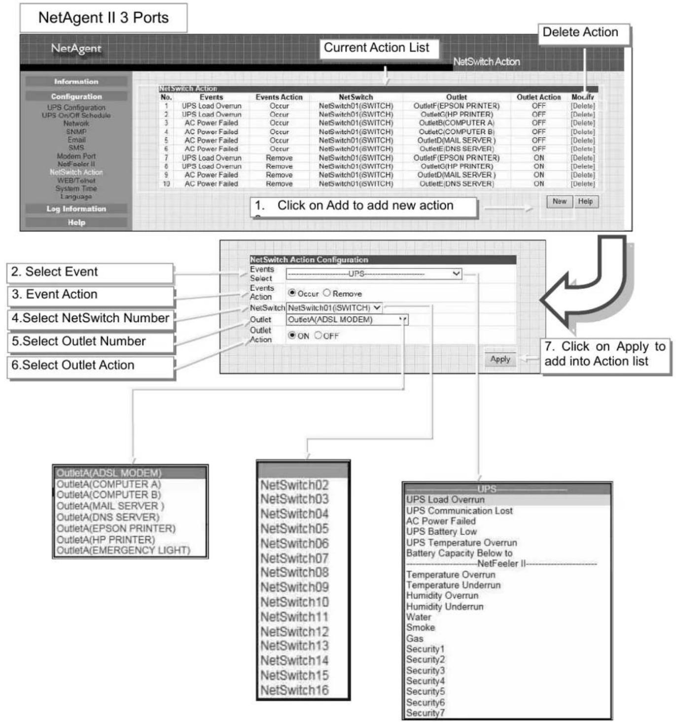
flowchart
graph TD
    A["NetAgent II 3 Ports"] --> B["Current Action List"]
    B --> C["Delete Action"]
    C --> D["NetSwitch Action"]
    D --> E["1. Click on Add to add new action"]
    E --> F["2. Select Event"]
    E --> G["3. Event Action"]
    E --> H["4. Select NetSwitch Number"]
    E --> I["5. Select Outlet Number"]
    E --> J["6. Select Outlet Action"]
    D --> K["NetSwitch Action Configuration"]
    K --> L["1. Select Event"]
    K --> M["2. Select Outlet Number"]
    K --> N["3. Select Outlet Action"]
    K --> O["4. Select NetSwitch Number"]
    K --> P["5. Select Outlet Number"]
    K --> Q["6. Select Outlet Action"]
    K --> R["NetSwitch02"]
    K --> S["NetSwitch03"]
    K --> T["NetSwitch04"]
    K --> U["NetSwitch05"]
    K --> V["NetSwitch06"]
    K --> W["NetSwitch07"]
    K --> X["NetSwitch08"]
    K --> Y["NetSwitch09"]
    K --> Z["NetSwitch10"]
    K --> AA["NetSwitch11"]
    K --> AB["NetSwitch12"]
    K --> AC["NetSwitch13"]
    K --> AD["NetSwitch14"]
    K --> AE["NetSwitch15"]
    K --> AF["NetSwitch16"]
    K --> AG["UPS Load Overrun"]
    K --> AH["UPS Communication Lost"]
    K --> AI["AC Power Failed"]
    K --> AJ["UPS Battery Low"]
    K --> AK["UPS Temperature Overrun"]
    K --> AL["Battery Capacity Below to NetFeeler II"]
    K --> AM["Temperature Overrun"]
    K --> AN["Temperature Underrun"]
    K --> AO["Humidity Overrun"]
    K --> AP["Humidity Underrun"]
    K --> AQ["Water"]
    K --> AR["Smoke"]
    K --> AS["Gas"]
    K --> AT["Security1"]
    K --> AU["Security2"]
    K --> AV["Security3"]
    K --> AW["Security4"]
    K --> AX["Security5"]
    K --> AY["Security6"]
    K --> AZ["Security7"]
- NetSwitch Settings
NetSwitchCommunication Port :
Select "ttyUSB0" for NetSwitch connects with NetAgent 9 directly ;
Select "NetSwitch" for NetSwitch connects with NetAgent II 3 Ports
Once click on Apply on NetAgent 3 ports model, NetAgent will reboot
Select NetSwitch :
Select the NetSwitch number (0\~16)
Address Change :
To adjust the current NetSwitch number (e.g : NetSwitch01→NetSwitch03)
Identification :
NetSwitch's ID name
Outlet :
Each NetSwitch as 8 individual outlet with code of A\~H
Name :
To enter a name for each outlet for identification
Phone Controllable :
If to control by phone coding (Refer to NetSwitch manual)
Control Type :
The action of each outlet. Safe Shutdown / Safe reboot / Instant Shutdown
(Refer to NetSwitch manual for definition of each outlet)
Power Off Delay :
When select safe shutdown and safe reboot, this is to set power off delay for the outlet
Power Resume Daly :
When AC recovers, the time to resume power on the outlet
NetAgent 9
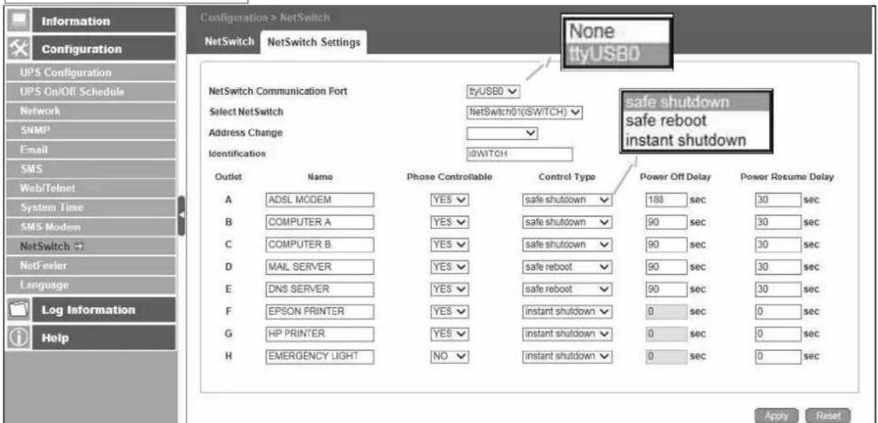
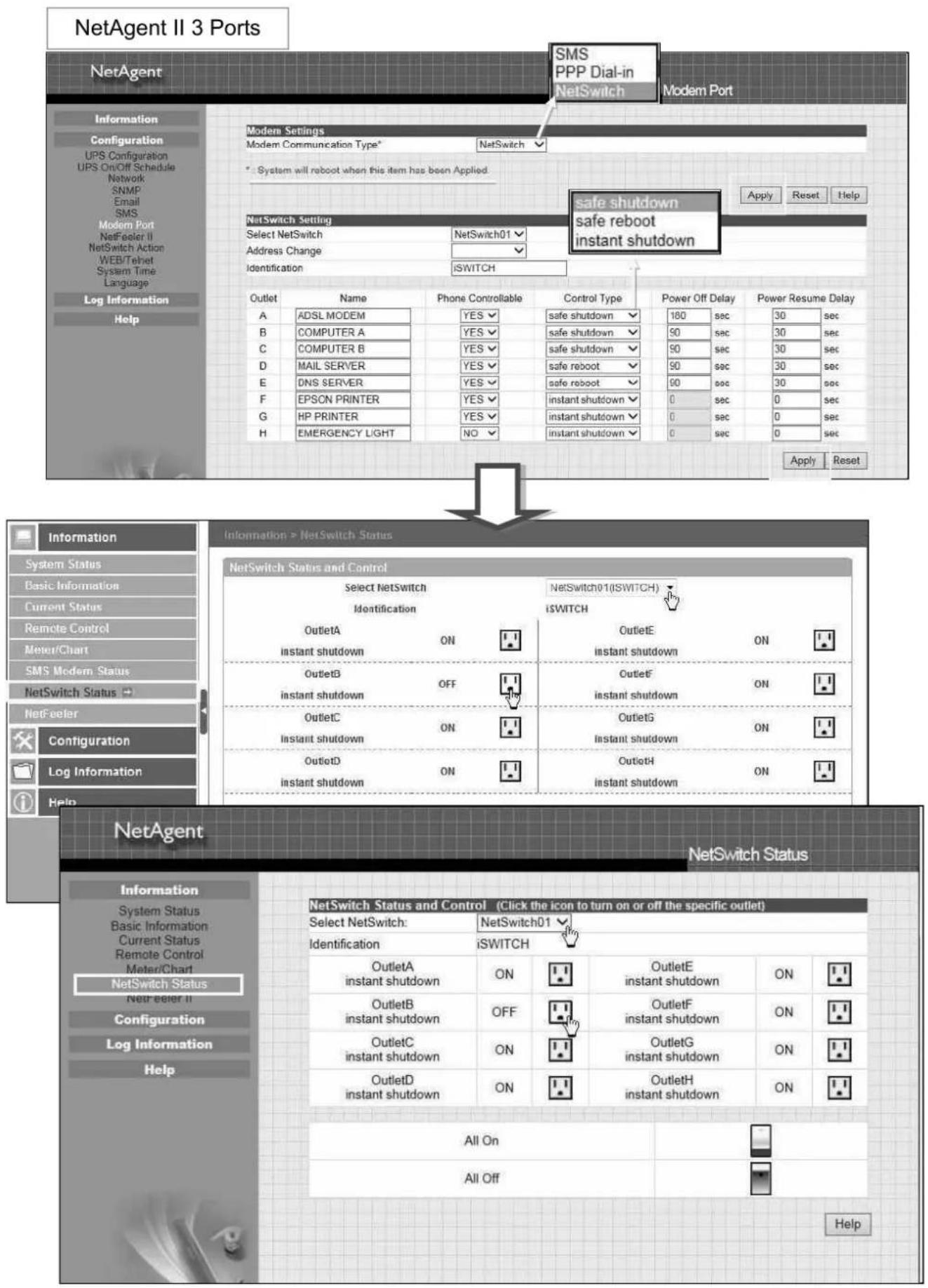
■ Configuration > NetFeeler
NetFeeler is the external optional environmental sensor, It is to detects temperature, humidity and water. Inside NetFeeler, it has RF receiver to work with extension sensors such as smoke, security sensor.
□ NetFeeler Setup
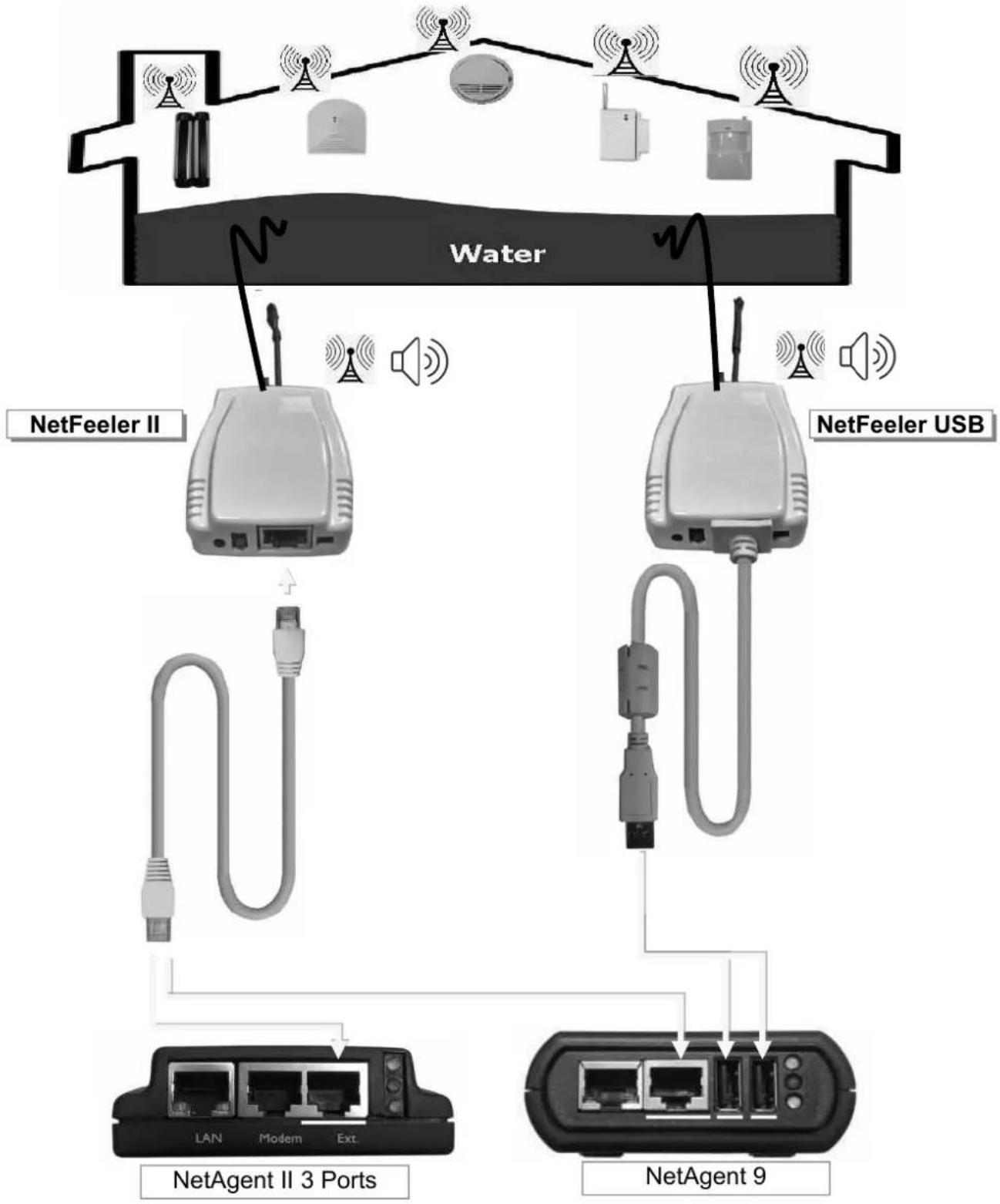
flowchart
graph TD
    A["Water"] --> B["NetFeeler II"]
    A --> C["NetFeeler USB"]
    B --> D["LAN"]
    B --> E["Modem"]
    B --> F["Ext."]
    C --> G["NetAgent II 3 Ports"]
    C --> H["NetAgent 9"]
NetFeeler
NetFeeler :
To select NetFeeler type. NetFeeler II / NetFeeler USB
NetAgent 9 can use with NetFeeler II or NetFeeler USB
●NetAgent II 3 Ports only to use with NetFeeler II
Humidity/Temperature Critical value :
To set the lowest and highest critical values for temperature and humidity. NetFeeler II will send a warning message when it detects temperature or humidity values below and above these settings.
Security Label
NetFeeler may connect up to 7 security sensors that communicates via RF. This section is to set the location or name of each sensor.
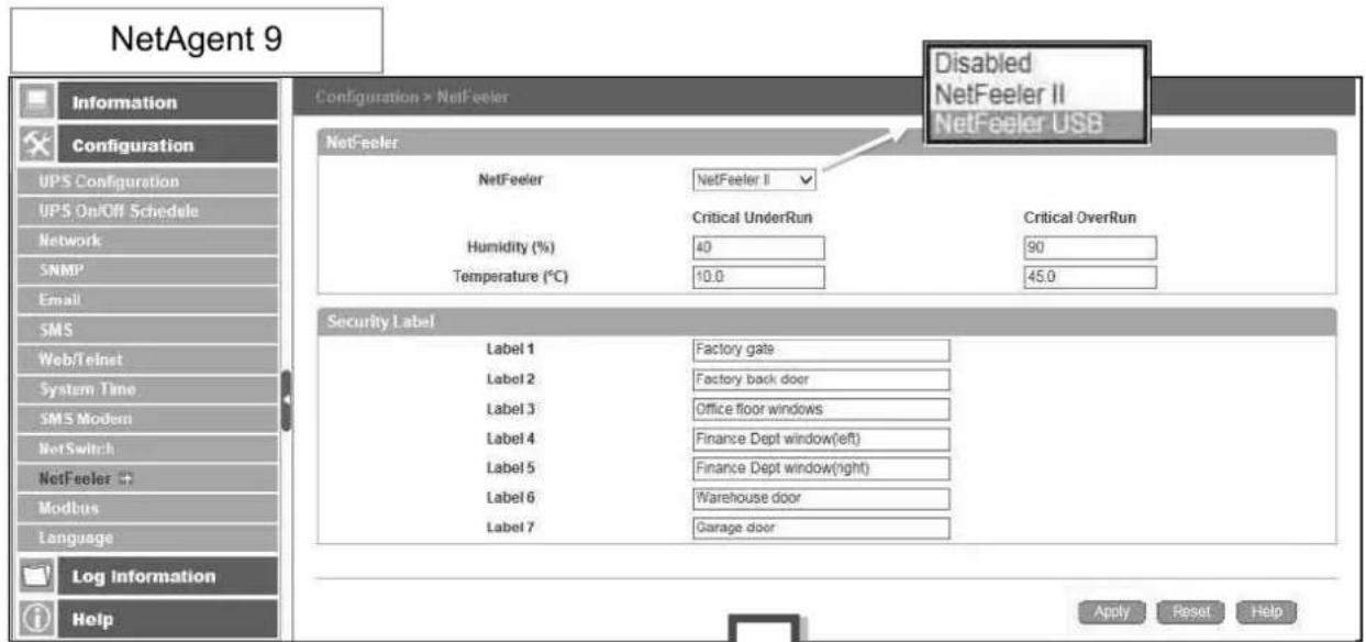
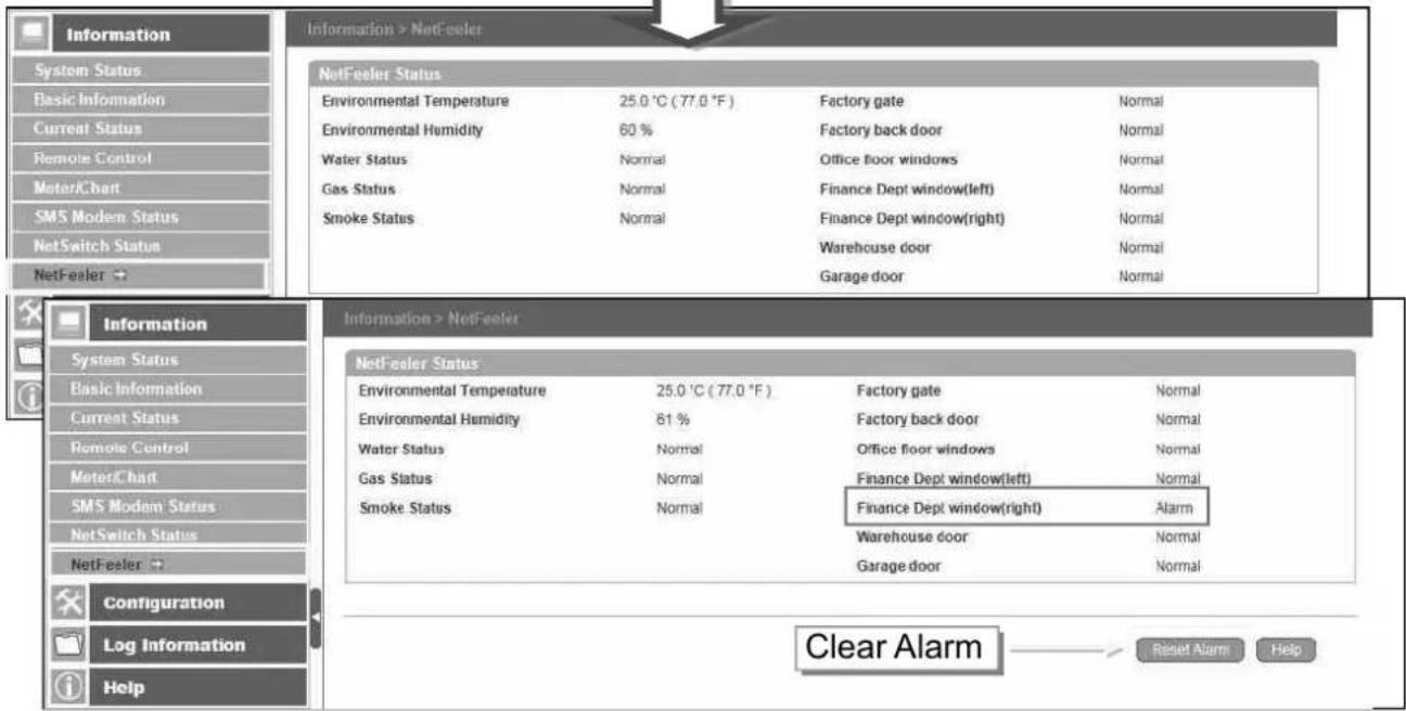
NetAgent II 3 Ports
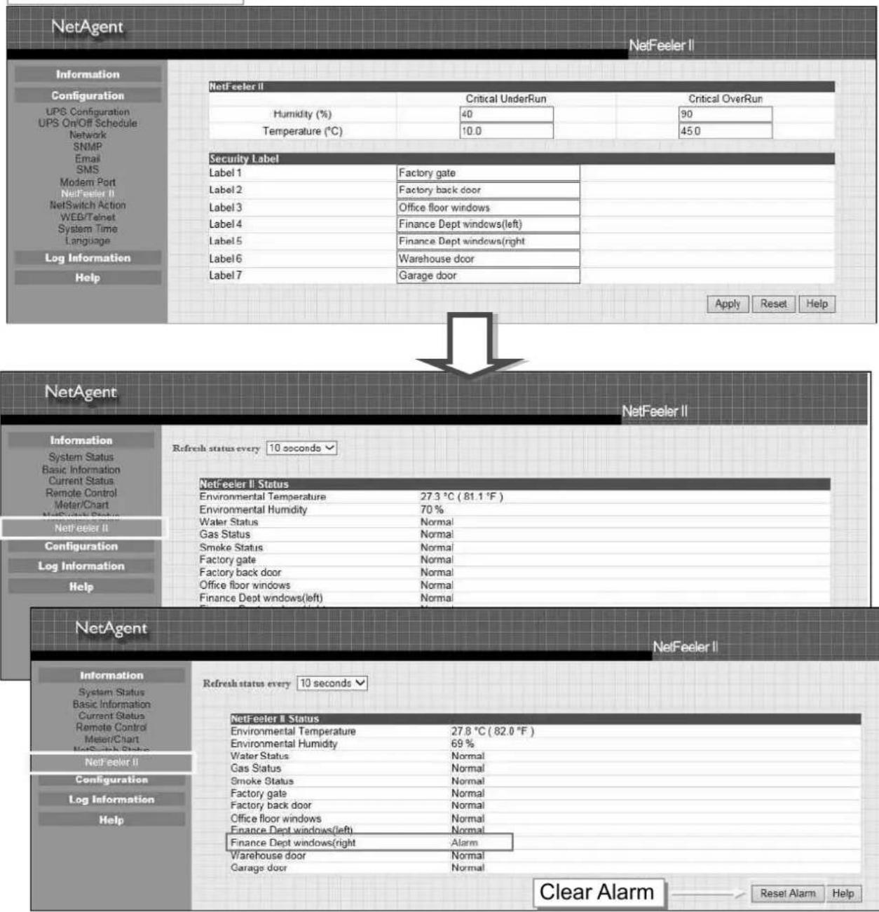
■ Configuration > MODBUS
NetAgent supports Modbus on TCP/IP. And NetAgent 9 BY model also supports ModBus on RS485. Through Ethernet and serial communication, it may read multi UPS's data.
Connection illustration as below
☐ RS485 2 lines connection(Half Duplex)
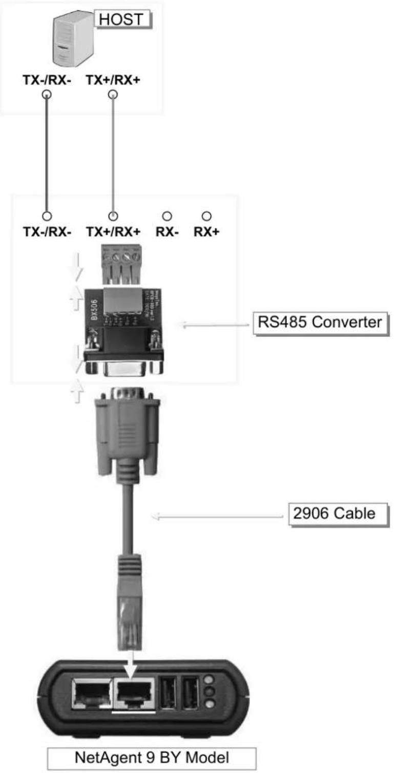
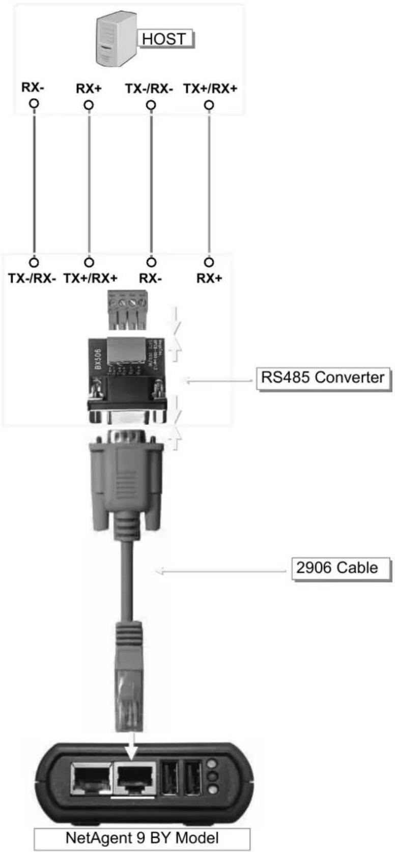
Modbus on TCP
Modbus on TCP Device ID :
Enter device ID to read/write data when when using Modbus on TCP communication
Modbus on RS485
Transmisson Mode :
To select Modbus communication code RTU or ASCII
Device ID :
Enter device ID
Mode :
To select communicate mode of Full Duplex and Half Duplex
Baud Rate :
Baud Rate of 2400 / 4800 / 9600 / 19200 / 38400 /57600 bps
Data bits :
Date bits of 8 bits / 7 bits
Parity :
Parity of None/ odd /even
Stop bits :
Stop bits of 1 / 2
NetAgent 9
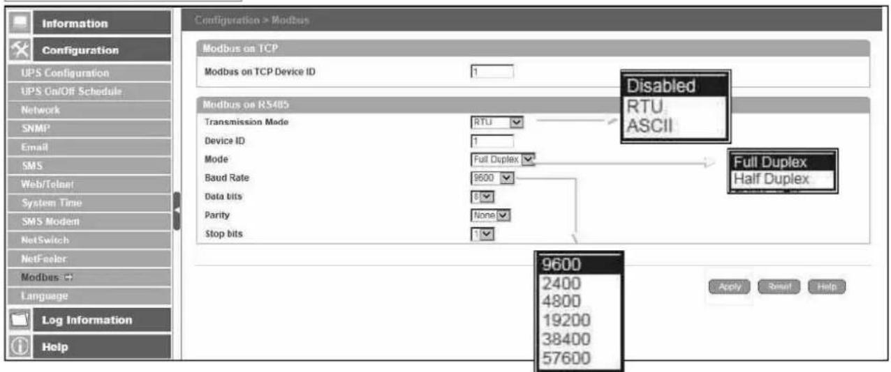
■ Configuration > Language
This page is to set the language interface for NetAgent.
Interface Language
To set the language of NetAgent web pages. When first start login to the webpage of NetAgent, NetAgent will auto detect the OS language of the PC and shows the same language on its web pages. Users may choose the language per preference Note: Users will have to enable cookies before they use this function.
Email Preference
Select language preference when receive emails and SMS.
Languages supported by NetAgent
NetAgent 9
- English
- Deutsch
- Português
- Español
- Français
- Italiano
-
Türkçe
-
繁體中文
- 簡體中文
- 한글
- 日本語
- Русский
- ไทย
- Polska
NetAgent II
EAST Version
- English
- 繁體中文
- 簡體中文
한글 - 日本語
- Русский
- ไทย
WEST Version
- English
- Deutsch
- Português
- Español
- Français
- Italiano
- Русский
- Türkçe
- Polska
NetAgent 9 Mini & NetAgent 9
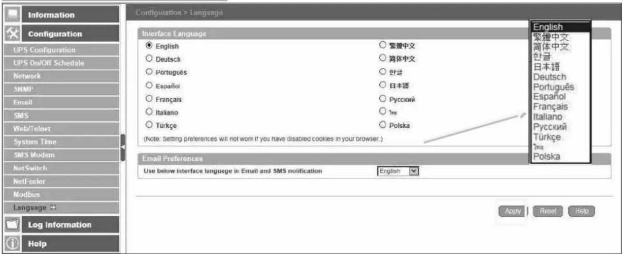
■ Log Information > Event Log
It shows record of all events, giving the Date/Time of the event and a detailed description of each. Log capacity is 1000 logs. When reach to the limit, it rewrites on the previous logs. Log can be save as csv file.
csv file name as below
NetAgent 9 → eventlog_year/month.csv, e.g.:eventlog_201706
NetAgent II → eventlog.csv, e.g.: eventlog.csv
NetAgent 9 Mini & NetAgent 9
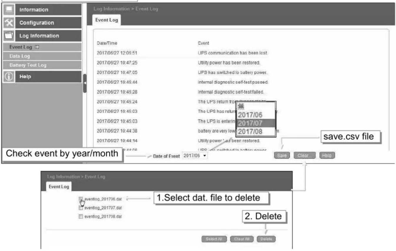
NetAgent Mini & NetAgent II
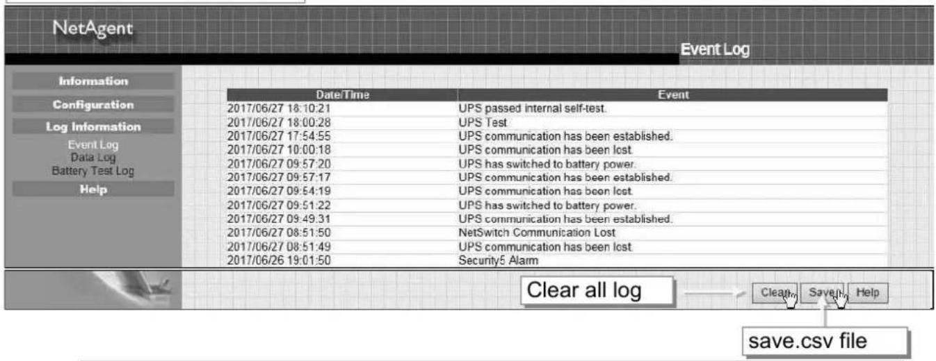
■ Log Information > SMS Log
It shows SMS record of all mobile number, giving the Date/Time of the SMS sent and a detailed description of each. Log capacity is 1000 logs. When reach to the limit, it rewrites on the previous logs.
NetAgent 9 model of BX/BY can save the SMS log as csv file.
csv file as below
smslog_year/month.csv, e.g: smslog_201706.csv
NetAgent 9
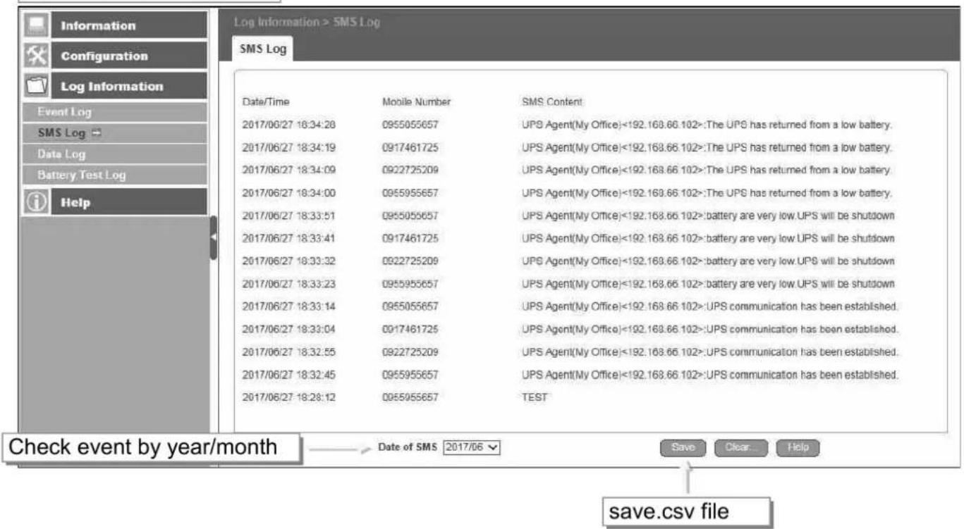
NetAgent II 3PORTS
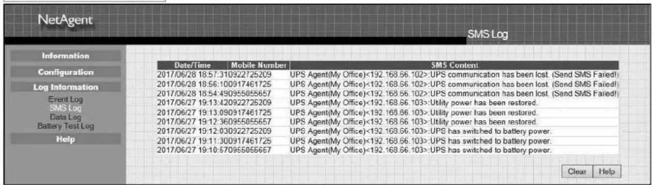
■ Log Information > Data Log
It records UPS Input Voltage/Output Voltage/ Frequency/ Loading/Capacity/ Temperature. When connects with NetFeeler, temperature, humidity will also be recorded. Log capacity is 5000 logs. When reach to the limit, it rewrites on the previous logs. Logs can be saved in CSV format by clicking on "Save Data Log".
csv file name as below
NetAgent 9 → datalog_year/month.csv, e.g.: datalog_201706
NetAgent II → upsdata.cs

NetAgent Mini & NetAgent II
NetAgent
Data Log
Information
Configuration
Log Information
Event Log
Data Log
Battery Test Log
Help
| Date/Time | Input Volt. | Output Volt. | Freq. (Hz) | Load | Capacity | Temp. | Env. Temp. | Env. Humidity |
| 2017/06/27 19:30:00 | 220.1 | 220.1 | 50.0 | 10 | 100 | 30.1°C 86.1°F | 26.4°C 79.5°F | 59 |
| 2017/06/27 19:29:00 | 220.1 | 220.1 | 50.0 | 10 | 100 | 30.1°C 86.1°F | 26.4°C 79.5°F | 59 |
| 2017/06/27 19:27:59 | 220.1 | 220.1 | 50.0 | 10 | 100 | 30.1°C 86.1°F | 25.9°C 78.6°F | 60 |
| 2017/06/27 19:26:58 | 220.1 | 220.1 | 50.0 | 10 | 100 | 30.1°C 86.1°F | 25.9°C 78.6°F | 60 |
| 2017/06/27 19:25:57 | 220.1 | 220.1 | 50.0 | 10 | 100 | 30.1°C 86.1°F | 25.9°C 78.6°F | 59 |
| 2017/06/27 19:24:57 | 220.1 | 220.1 | 50.0 | 10 | 100 | 30.1°C 86.1°F | 25.9°C 78.6°F | 58 |
| 2017/06/27 19:23:56 | 220.1 | 220.1 | 50.0 | 10 | 100 | 30.1°C 86.1°F | 25.9°C 78.6°F | 59 |
| 2017/06/27 19:10:23 | 220.1 | 220.1 | 50.0 | 10 | 100 | 30.1°C 86.1°F | 26.4°C 79.5°F | 59 |
Clear
Save Data Log
Help
■ Log Information > Battery Test Log
To record the UPS Self-Test and it shows in graphic. UPS Self-Test option is available under System Information > Remote Contro.
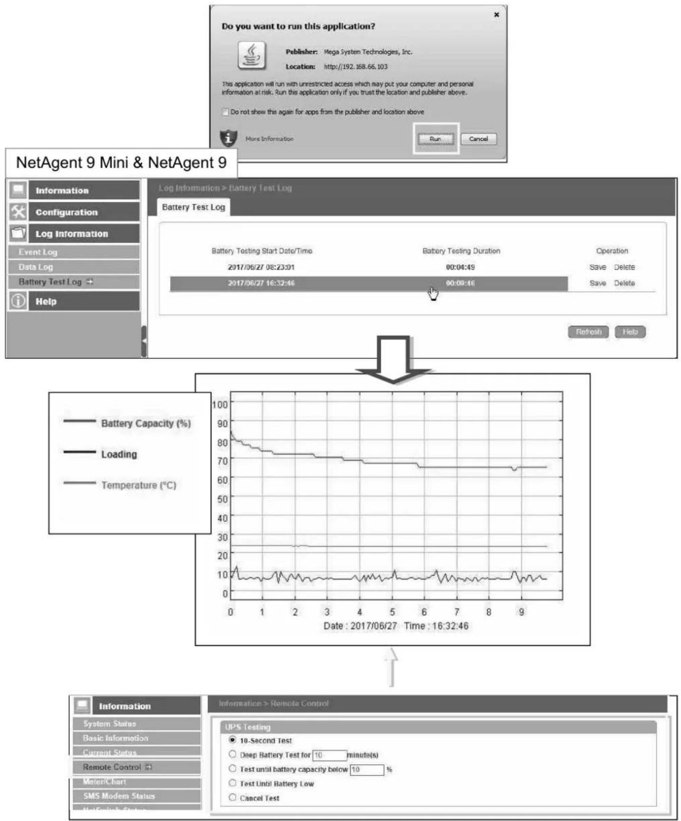
flowchart
graph TD
    A["Do you want to run this application?"] --> B["Publisher: Mega System Technologies, Inc."]
    B --> C["Location: http://192.168.66.103"]
    C --> D["This application will run with unrestricted access which may put your computer and personal information at risk. Run this application only if you trust the location and publisher above."]
    D --> E["Do not show this again for apps from the publisher and location above"]
    E --> F["More Information"]
    F --> G["Run"]
    F --> H["Cancel"]
    I["NetAgent 9 Mini & NetAgent 9"] --> J["Information"]
    I --> K["Configuration"]
    I --> L["Log Information"]
    I --> M["Event Log"]
    I --> N["Data Log"]
    I --> O["Battery Test Log"]
    I --> P["Help"]
    Q["Log Information > Battery Test Log"] --> R["Battery Test Log"]
    R --> S["Battery Testing Start Date/Time: 2017/06/27 08:23:01"]
    R --> T["Battery Testing Duration: 00:04:49"]
    R --> U["Operation: Save Delete"]
    R --> V["2017/06/27 16:32:46"]
    R --> W["00:09:46"]
    X["Refresh"] --> Y["Help"]
    Z["Battery Capacity (%)"] --> AA["Battery Capacity (%)"]
    AB["Loading"] --> AC["Loading (%)"]
    AD["Temperature (°C)"] --> AE["Temperature (°C)"]
    AF["Date : 2017/06/27 Time : 16:32:46"] --> AG["Line chart showing battery performance metrics over time"]
    AH["Information"] --> AI["System Status"]
    AH --> AJ["Basic Information"]
    AH --> AK["Current Status"]
    AH --> AL["Remote Control"]
    AH --> AM["MeterChart"]
    AH --> AN["SMS Modem Status"]
    AH --> AO["NetAgent 9 Mini & NetAgent 9"]
    AP["UPS Testing"] --> AQ["10-Second Test"]
    AP --> AR["Deep Battery Test for 10 minute(s)"]
    AP --> AS["Test until battery capacity below 10 %"]
    AP --> AT["Test Until Battery Low"]
    AP --> AU["Cancel Test"]
NetAgent Mini & NetAgent II
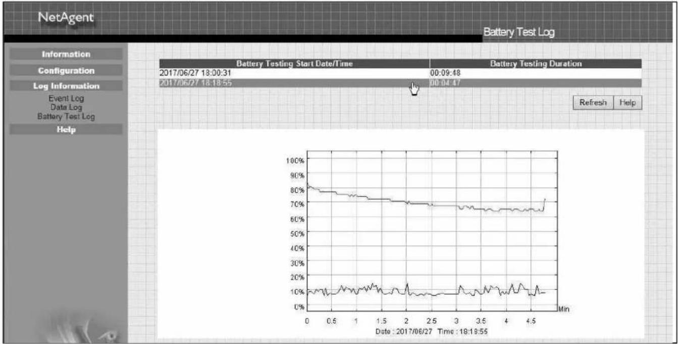
line
| Date | Value | | ---------- | ----- | | 2017/06/27 18:00:31 | 00:09:48 | | 2017/06/27 18:18:55 | 00:04:47 | | 2017/06/27 18:18:55 | Min |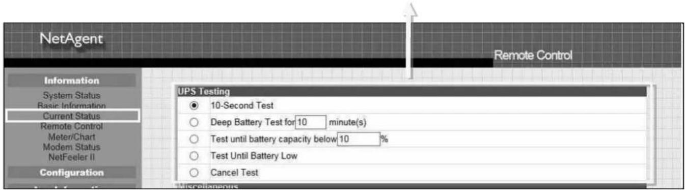
■ Help > Search NetAgent
This to display all the found NetAgent within network with its serial number; Mac Address; Hardware/Firmware version and its IP address. Double click on the highlighted unit to open the webpage of such device.
NetAgent 9 Mini & NetAgent 9
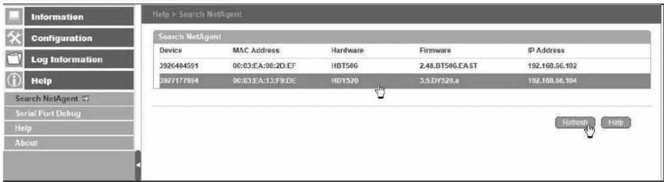
NetAgent Mini & NetAgent II
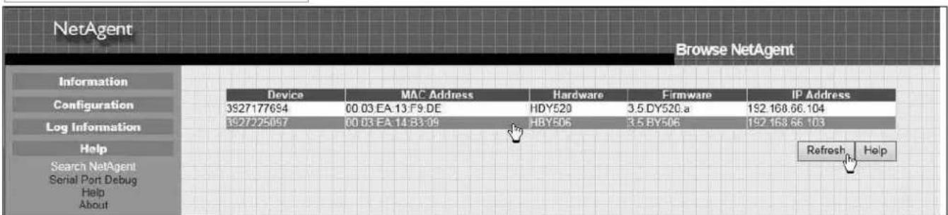
■ Help > Serial Port Debug
It shows the communication status between NetAgent and UPS by Sent and Received columns. Command can send automatically by NetAgent, or manually enter the command to UPS. (Java is required)
Port Information
This is to configure the communication parameter between NetAgent and UPS. Parameters are Debug Mode; Port; Speed (Baud), Data Bits; Parity and Stop Bits. Two encoding formats: ASCII or Hexadecimal. If Debug mode is set as manually, user may enter its parameter under Send Contents column.
Sent Information
This column shows the real time sent command
Received Information
This display the response that NetAgent receives from UPS
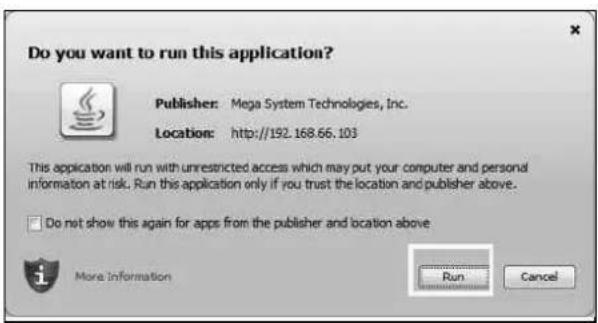
NetAgent 9 Mini & NetAgent 9
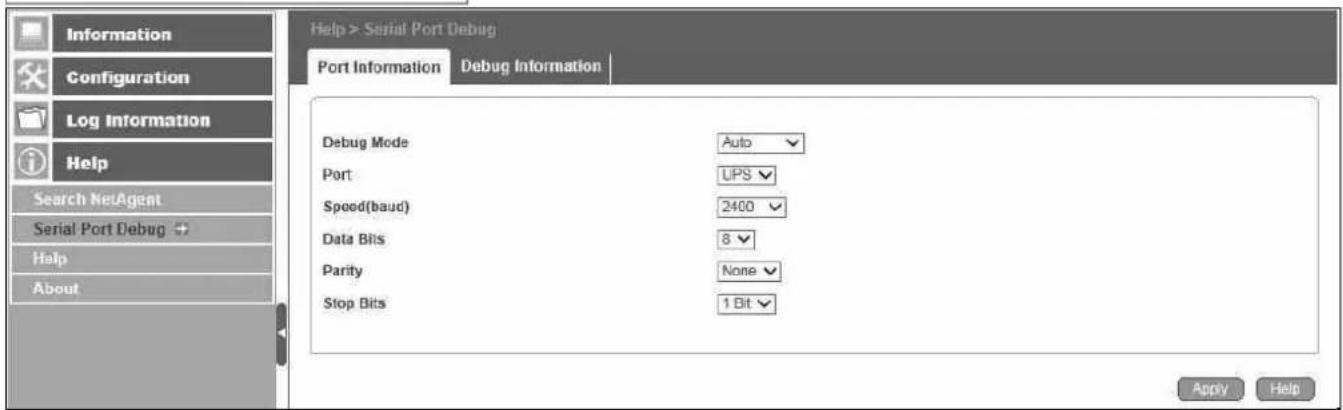
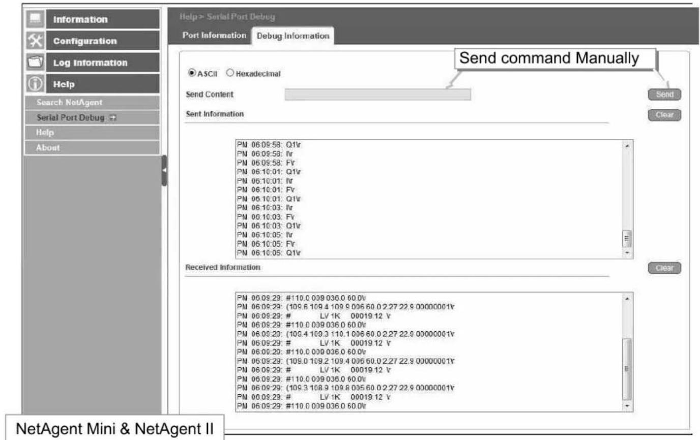
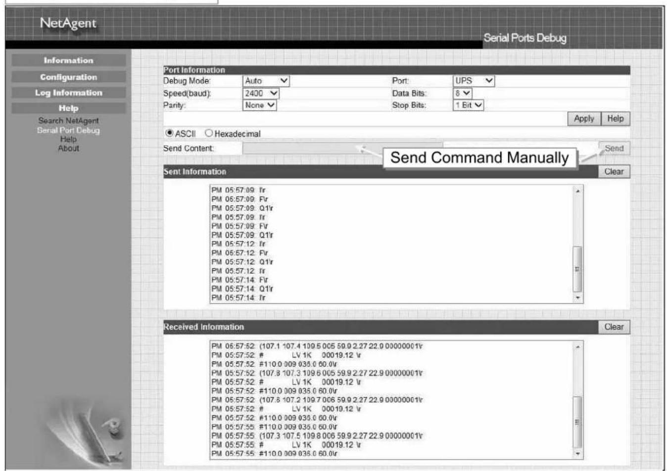
■ Help > Help
This is to help to illustrate each feature/option that NetAgent offers
NetAgent 9 Mini & NetAgent 9
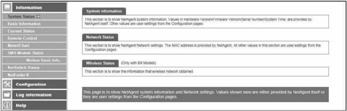
NetAgent Mini & NetAgent II
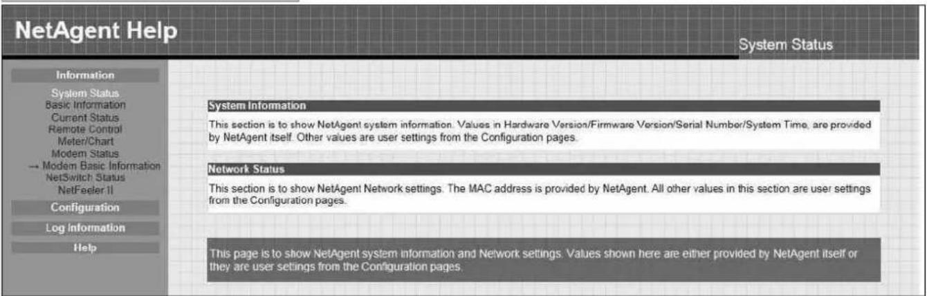
■ Help > About
About
It shows NetAgent's hardware/firmware and serial number.
Save Current Configuration
Click on Save to save the configuration to your PC. The text file will have a default format of YYYY_MMDD_####.cfg. Administrator permission required.
Restore previous configuration
Use this function to restore a *.cfg configuration that has been saved earlier. Click Browse... to the location of the file and click Restore.
Reset to factory default
This function will reset all settings to its default value.
NetAgent 9 Mini & NetAgent 9
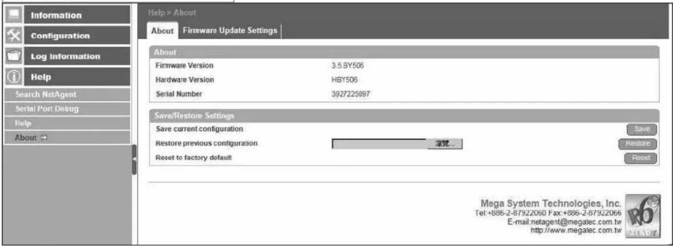
Firmware Update Settings
Default FTP server is set as ftp.icv99.com with its username/password. Click on Update Now, NetAgent will connects to the FTP server and upgrade to the latest firmware version accordingly. Or, it could upgrade per preset time
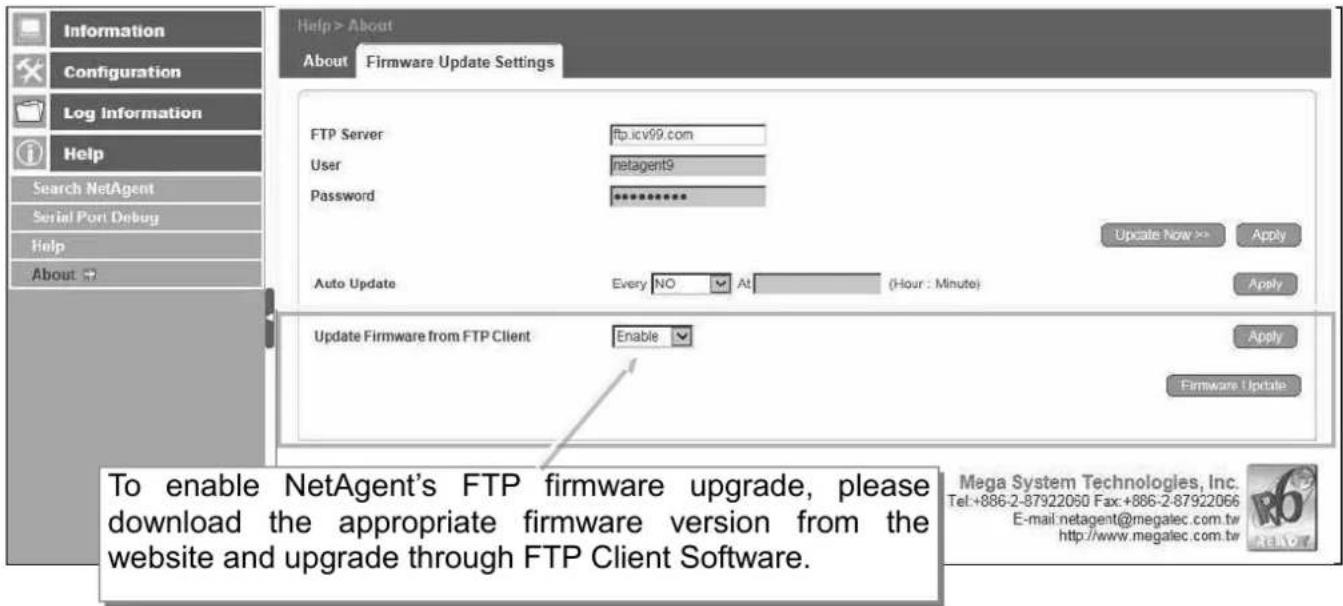
NetAgent Mini & NetAgent II
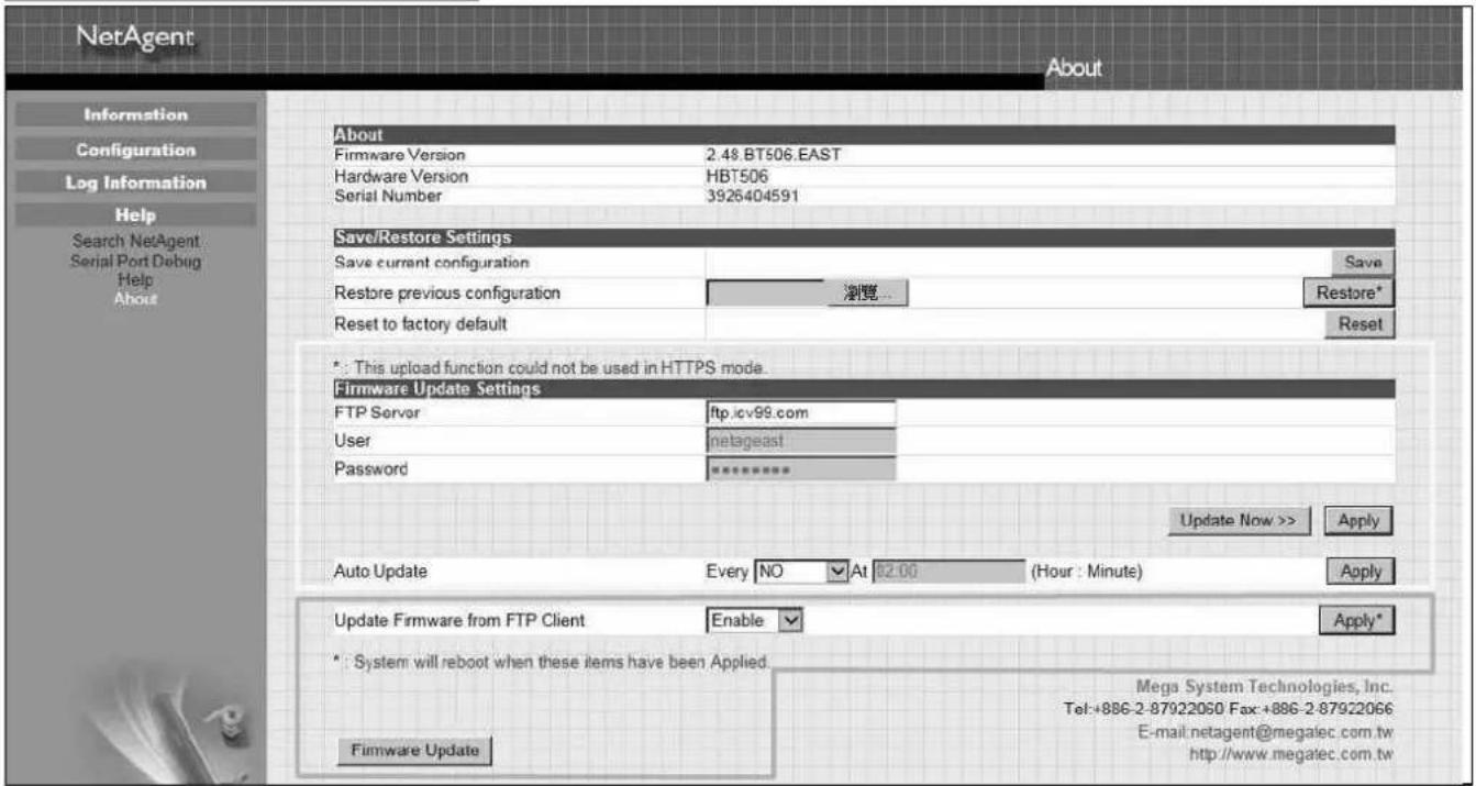
Update Firmware from FTP Client
-Select on Enable
-Download the appropriate firmware version from website (http://www.megatec.com.tw)
-Unzip the file and known the directory path
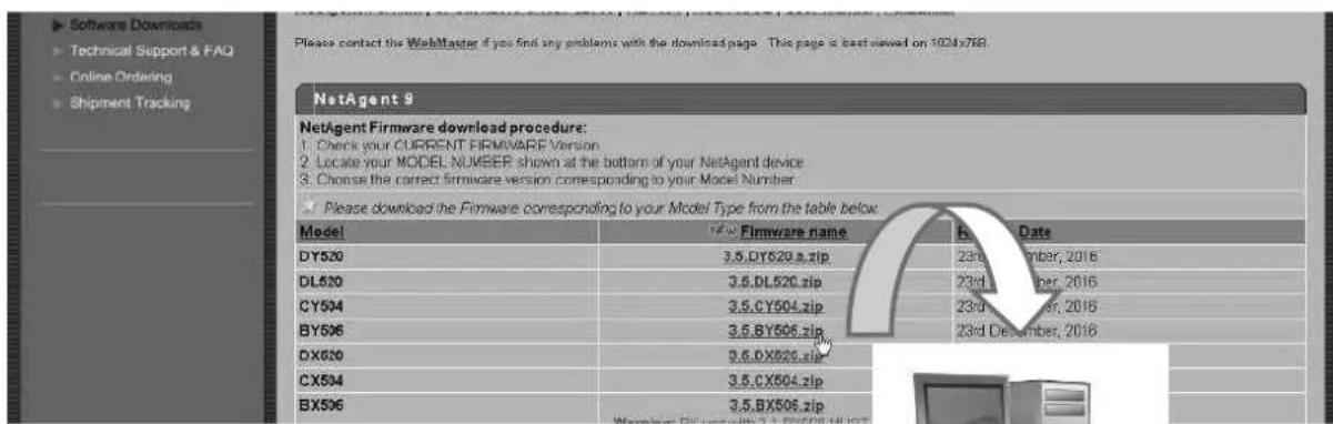
-Execute ftp + NetAgent's IP address
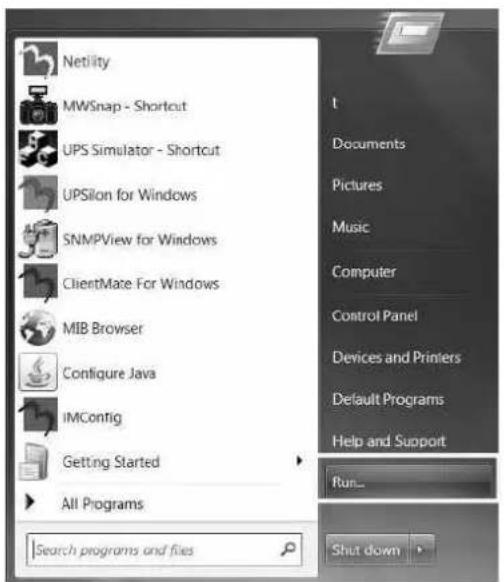

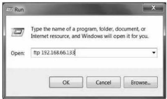
-FTP login
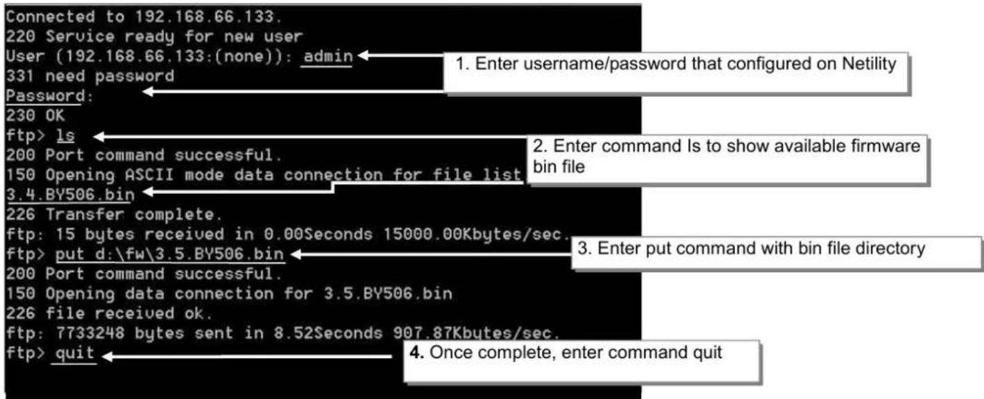
Chapter 5. Telnet/ SSH
Despite to login to the NetAgent's webpage, it could also access via Telnet or SSH
- Ensure NetAgent port 22 is enabled when using SSH connection and username/password are required.
When using Telnet, port 23 must be enabled
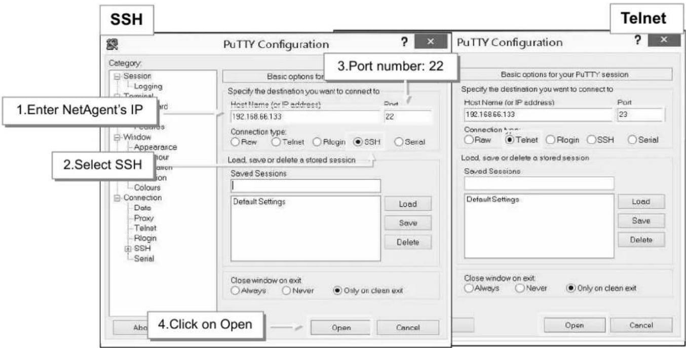

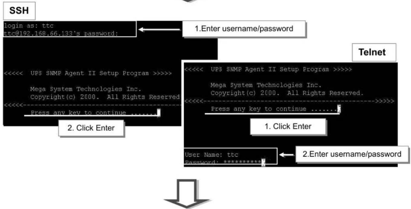
flowchart
graph TD
    A["login as: ttc<br>ttc@192.168.66.133's password:"] --> B["1.Enter username/password"]
    B --> C["2. Click Enter"]
    C --> D["User Name: ttc<br>Password: *********"]
    D --> E["1. Click Enter"]
    E --> F["2.Enter username/password"]
Enter to the Main Menu and enter the number of the option under Select => and press ENTER
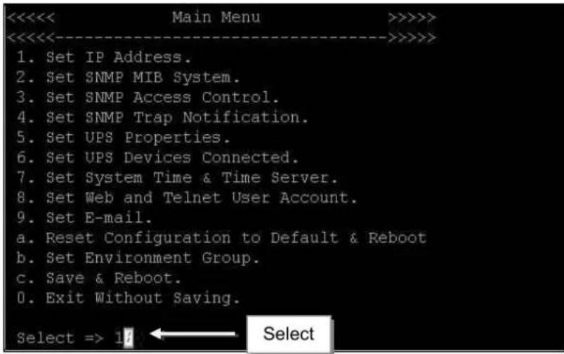
- Set IP Address :
This function allows you to setup IP Address, Gateway Address, Subnet Mask
- Set SNMP MIB System :
To set the MIB system group parameters.
- Set SNMP Access Control :
To set the Manager IP, Community, Access Permission.
- Set SNMP Trap Notification :
To set Trap notification
- Set UPS Properties :
To setup the Communication Type of UPS, UPS Device Name and Battery Replacement Date.
- Set UPS Device Connect :
To setup the System Name, Rating which connected., Connected.
- Set System Time & Time Server :
To setup the System date, time and two time servers.
- Set Web and Telnet user Account :
This is allows to set users account's authority.
9.Set E-mail :
To set e-mail accounts to receive power event notification for emergency management.
a. Reset configuration to Default & Reboot :
Set all values to their default settings.
b.Set Environment Group :
To set critical value for environmental sensor
c.Save & Reboot :
Save the current configuration data, including any changes you have made, and reboot the Net Agent.
0.Exit Without Saving :
Exit, all configuration changes will be lost
Chapter 6. ClientMate
ClientMate is shutdown software for PC that connects with NetAgent. This utility is for the Windows platform. When the ClientMate gets the power failure signal from the NetAgent. The ClientMate will save the files and shutdown the system gracefully. When the hardware installation of the NetAgent has been completed, install the ClientMate on any of the Windows system on the network. When ClientMate detects AC Fail, Battery Low, Schedule Shutdown signals from the NetAgent, it will save the file and shutdown the system gracefully to avoid system crash.
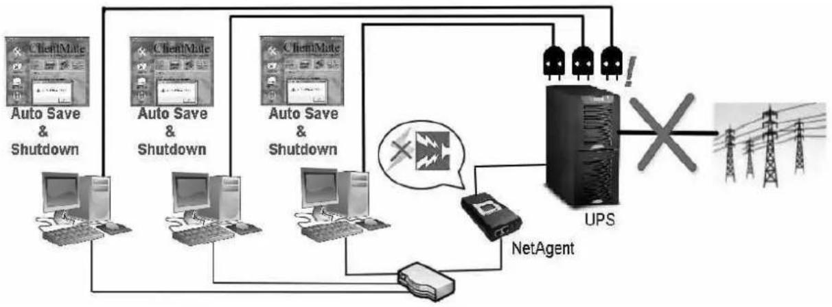
flowchart
graph TD
    A["ClientMate"] --> B["Auto Save & Shutdown"]
    C["ClientMate"] --> D["Auto Save & Shutdown"]
    E["ClientMate"] --> F["Auto Save & Shutdown"]
    G["ClientMate"] --> H["Auto Save & Shutdown"]
    I["ClientMate"] --> J["Auto Save & Shutdown"]
    K["ClientMate"] --> L["Auto Save & Shutdown"]
    M["ClientMate"] --> N["Auto Save & Shutdown"]
    O["ClientMate"] --> P["Auto Save & Shutdown"]
    Q["ClientMate"] --> R["Auto Save & Shutdown"]
    S["ClientMate"] --> T["Auto Save & Shutdown"]
    U["ClientMate"] --> V["Auto Save & Shutdown"]
    W["ClientMate"] --> X["Auto Save & Shutdown"]
    Y["ClientMate"] --> Z["Auto Save & Shutdown"]
    AA["ClientMate"] --> AB["Auto Save & Shutdown"]
    AC["ClientMate"] --> AD["Auto Save & Shutdown"]
    AE["ClientMate"] --> AF["Auto Save & Shutdown"]
    AG["ClientMate"] --> AH["Auto Save & Shutdown"]
    AI["ClientMate"] --> AJ["Auto Save & Shutdown"]
    AK["ClientMate"] --> AL["Auto Save & Shutdown"]
    AM["ClientMate"] --> AN["Auto Save & Shutdown"]
    AO["ClientMate"] --> AP["Auto Save & Shutdown"]
    AQ["ClientMate"] --> AR["Auto Save & Shutdown"]
    AS["ClientMate"] --> AT["Auto Save & Shutdown"]
    AU["ClientMate"] --> AV["Auto Save & Shutdown"]
    AW["ClientMate"] --> AX["Auto Save & Shutdown"]
    AY["UPS"] --> AZ["NetAgent"]
    AZ --> AA
    BB["Pump"] --> AA
    BC["Pump"] --> AA
    AD["Pump"] --> AA
    AE["Pump"] --> AA
    AF["Pump"] --> AA
    AG["Pump"] --> AA
    AH["Pump"] --> AA
    AI["Pump"] --> AA
    AJ["Pump"] --> AA
    AK["Pump"] --> AA
    AL["Pump"] --> AA
    AM["Pump"] --> AA
    AN["Pump"] --> AA
    AO["Pump"] --> AA
    AP["Pump"] --> AA
    AQ["Pump"] --> AA
    BB["Pump"] --> AA
    BC["Pump"] --> AA
    AD["Pump"] --> AA
    AE["Pump"] --> AA
    AF["Pump"] --> AA
    AG["Pump"] --> AA
    AH["Pump"] --> AA
    AI["Pump"] --> AA
    AJ["Pump"] --> AA
    AK["Pump"] --> AA
Installation and setup
ClientMate software is available in the CD provided with NetAgent. After installed, it save under directory of
All Program >NetAgent > ClientMate > ClientMate for Windows
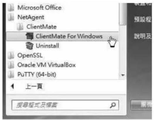
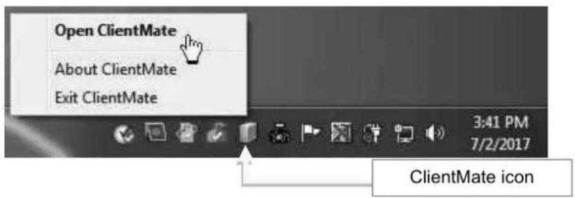
Operation Interface
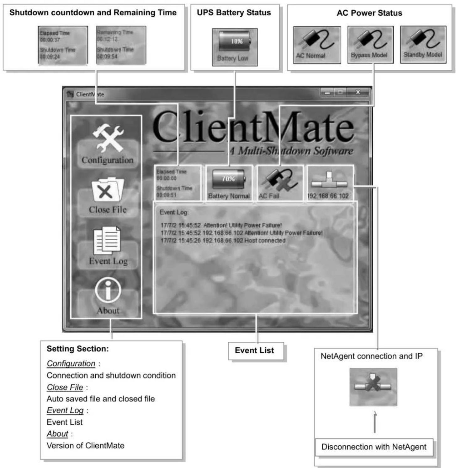
Configuration
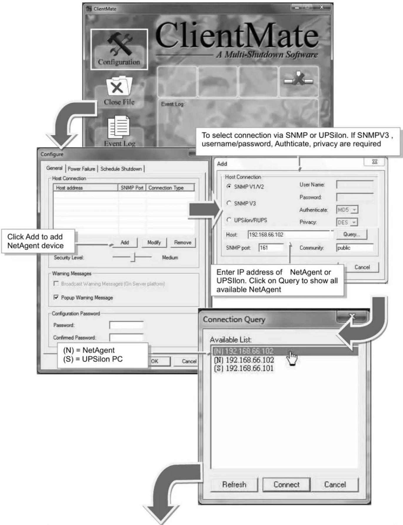
flowchart
graph TD
    A["ClientMate"] --> B["Configuration"]
    B --> C["Host Connection"]
    C --> D["SNMP Port"]
    C --> E["Connection Type"]
    D --> F["Add"]
    E --> G["Modify"]
    E --> H["Remove"]
    F --> I["Security Level:  Medium"]
    G --> J["Add"]
    H --> K["Add"]
    L["To select connection via SNMP or UPSilon. If SNMPV3, username/password, Authenticate, privacy are required"] --> M["Host: 192.168.66.102"]
    M --> N["Query..."]
    O["Enter IP address of NetAgent or UPSilon. Click on Query to show all available NetAgent"] --> P["Connection Query"]
    P --> Q["Available List: (N) 192.168.66.102 (S) = UPSilon PC"]
    Q --> R["Refresh"]
    Q --> S["Connect"]
    Q --> T["Cancel"]


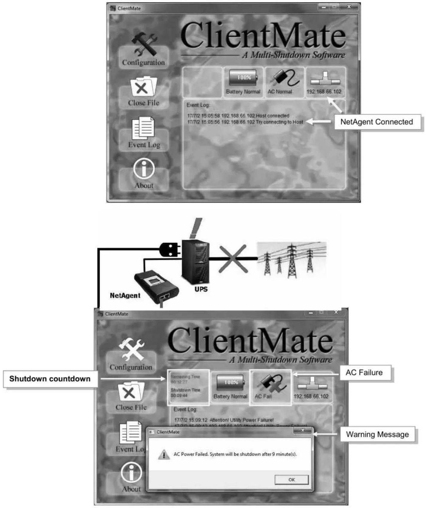
Close File
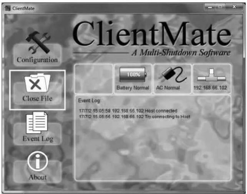
If select to auto save file before shutdown, ClientMate will save the file and file can be check from Closed File
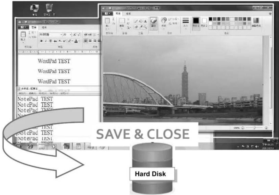
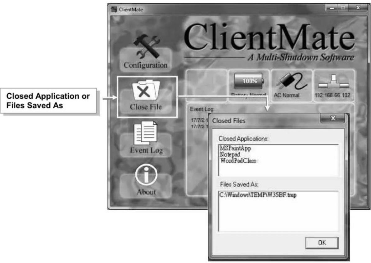
Event Log

About
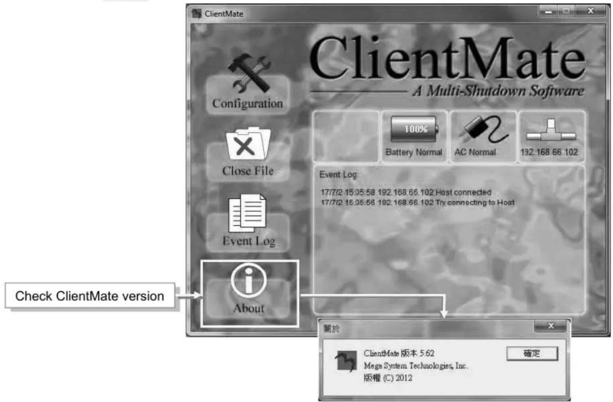
Chapter 7. SNMP View
SNMPView is a NMS software to remotely monitor and control multiple UPS with NetAgent.. When an event occurs, SNMPView can be programmed to send an email or trapr to inform the designated network manager. It can also inform the user of the UPS current condition or configuration, perform self-test, send a history file, turn the UPS On/Off and more.
Installation and setup
SNMP View software is available in the CD provided with NetAgent. After installed, it saves under directory of
All Programs >NetAgent > SNMPView > SNMP for Windows
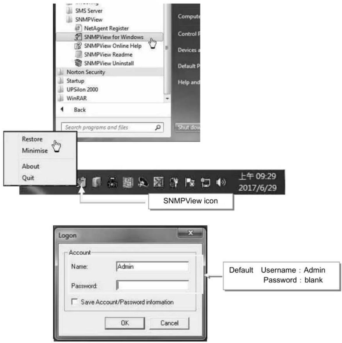
Operation Interface

flowchart
graph TD
    A["Setting Section"] --> B["Group Station"]
    B --> C["Connection Information"]
    C --> D["NetAgent and UPS Info"]
    D --> E["NetFeeler Status"]
    E --> F["Disconnection between NetAgent and UPS"]
    F --> G["Connection normal with NetAgent"]
    F --> H["Disconnect with NetAgent"]
    F --> I["AC Failed"]
    F --> J["UPS battery low"]
    F --> K["Bypass mode"]
Setting Tab/Device
Device
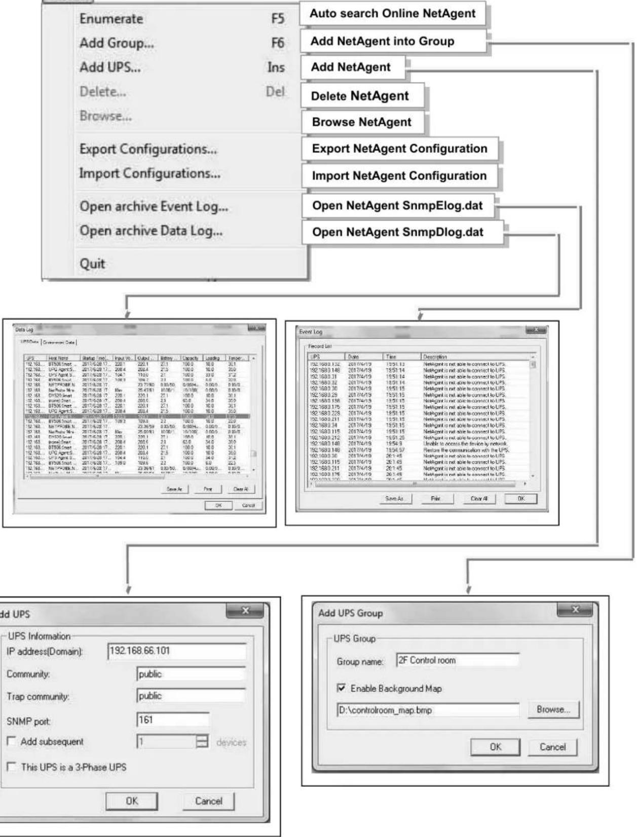
flowchart
UML event log and UPS group configuration flowchart, showing relationships between NetAgent, Export/Import configurations, and network routing.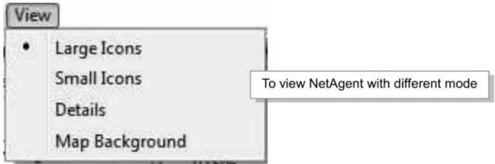
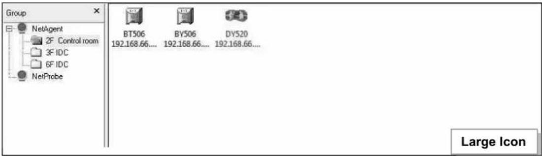
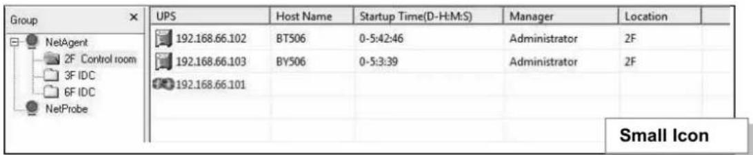
| Group | UPS | Host Name | Location | Output Status | Connection Status | Temperature | Loading | Output Volta... | Capacity | AC Status | Battery Status | NetFeeler II | Manager |
| NetAgent 2F Control room 3F IDC 4F IDC NetProbe | 192.168.66.102 | BT506 | ZF | AC mode | Connection Normal | 30.1 | 10.0 | 220.1 | 100% | AC Normal | Battery Normal | Have | Administrator |
| 192.168.66.103 | BY506 | ZF | AC mode | Connection Normal | 30.1 | 10.0 | 220.1 | 100% | AC Normal | Battery Normal | Have | Administrato... | |
| 192.168.66.101 | DY520 | Off-Line | Off-Line | Off-Line | Off-Line | Off-Line | Off-Line | Off-Line | Off-Line | Off-Line | Off-Line | Off-Line | |
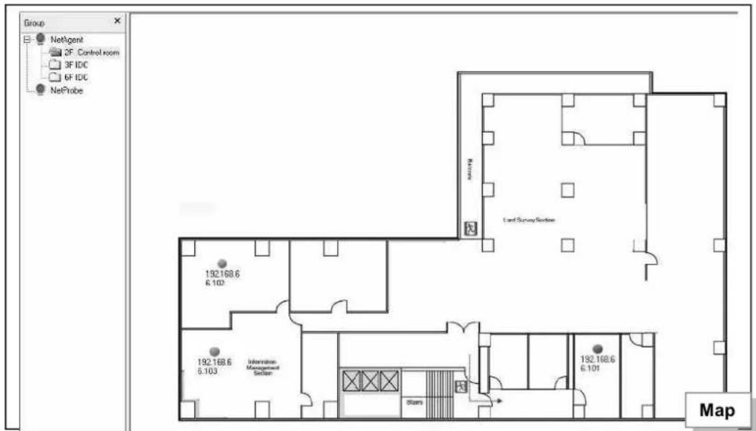
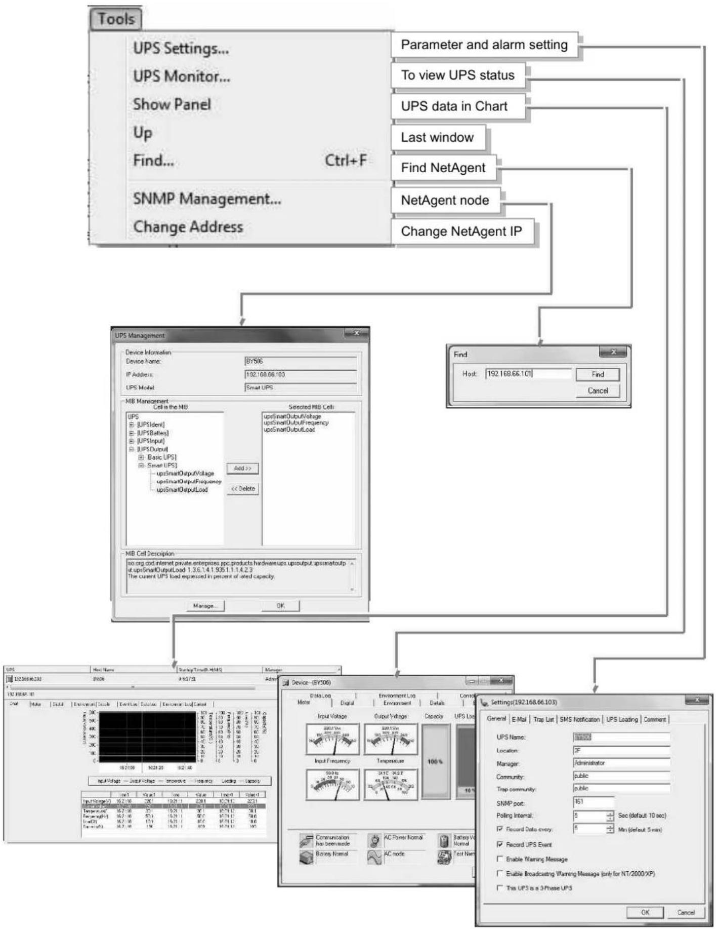
flowchart
graph TD
    A["Tools"] --> B["UPS Settings..."]
    B --> C["Parameter and alarm setting"]
    B --> D["To view UPS status"]
    B --> E["UPS data in Chart"]
    B --> F["Last window"]
    B --> G["Find NetAgent"]
    B --> H["NetAgent node"]
    B --> I["Change NetAgent IP"]
    A --> J["SNMP Management..."]
    J --> K["Change Address"]
    J --> L["Device Information: BY506"]
    J --> M["IP Address: 192.168.66.103"]
    J --> N["LPS Model: Smart UPS"]
    A --> O["MB Management Cell in the MB"]
    O --> P["Selected MIB Cells: upsSmartOutputVoltage, upsSmartOutputFrequency, upsSmartOutputLoad"]
    O --> Q["Add >"]
    Q --> R["<< Delete"]
    O --> S["MIB Cell Description: no.org dot internet private enterprises pcc products hardware ups up/output up smartout up at upsSmartOutputLoad 1.3.6.1.4.1.935.1.1.1.4.2.3 The current UPS load expressed in percent of rated capacity."]
    A --> T["Device—SY306"]
    T --> U["Settings(192.168.66.103)"]
    U --> V["General E-Mail Trap List SMS Notification UPS Loading Comment"]
    U --> W["UPS Name: 19200"]
    U --> X["Location: 2F"]
    U --> Y["Manager: Administrator"]
    U --> Z["Community: public"]
    U --> AA["Trap community: public"]
    U --> AB["SNMP port: N1"]
    U --> AC["Polling Interval: 5 Sec (default 10 sec)"]
    U --> AD["Record UPS Event: Min (default 5 sec)"]
    U --> AE["Enable Warning Message:  Enable Broadcasting Warning Message (only for NT/2000 XP)"]
    U --> AF["This UPS is a 3-Phase UPS"]
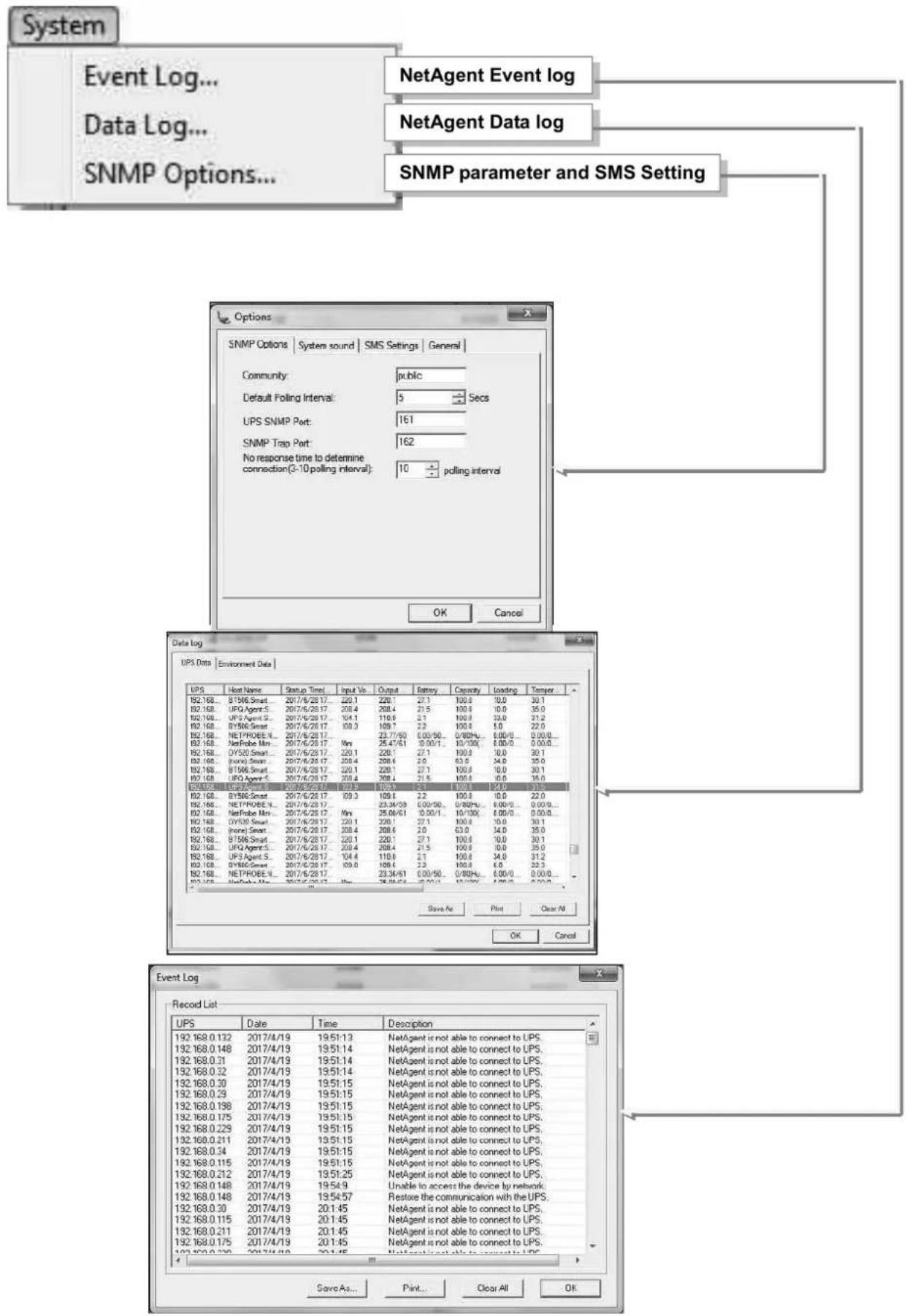
flowchart
graph TD
    A["System"] --> B["Event Log..."]
    A --> C["Data Log..."]
    A --> D["SNMP Options..."]
    B --> E["NetAgent Event log"]
    C --> F["NetAgent Data log"]
    D --> G["SNMP parameter and SMS Setting"]
    H["Options"] --> I["SNMP Options"]
    I --> J["Community: public"]
    I --> K["Default Folding Interval: 5 Secs"]
    I --> L["UPS SNMP Port: 161"]
    I --> M["SNMP Trap Port: 162"]
    I --> N["No response time to determine connection(3-10 polling interval): 10 polling interval"]
    O["Data log"] --> P["UPS Data Environment Data"]
    P --> Q["Host Name Startup Time Input Vs Output Battery Capacity Loading Temperature"]
    Q --> R["B2.168_B156_Smart_2017/6/28/17 220.1 220.1 27.1 100.0 10.0 30.1"]
    Q --> S["B2.168_UPQ_Agent_S_2017/6/28/17 205.4 205.4 27.5 100.0 0.0 35.0"]
    Q --> T["B2.168_UPQ_Agent_S_2017/6/28/17 164.1 110.9 2.1 100.0 33.0 31.2"]
    Q --> U["B2.168_BY56_Smart_2017/6/28/17 100.3 109.7 2.2 100.0 5.0 22.0"]
    Q --> V["B2.168_NEYPROBE_V_2017/6/28/17 23.77/50 0.00/50... 0/80Hz... 0.00/0 ... 0.00/0..."]
    Q --> W["B2.168_NetProbe_Min_2017/6/28/17 Min 25.47/51 0.00/1... 10/100 0.00/0 ... 0.00/0..."]
    Q --> X["B2.168_OY52O_Smart_2017/6/28/17 220.1 220.1 27.1 100.0 10.0 30.1"]
    Q --> Y["B2.168_Bondi_Smart_2017/6/28/17 259.4 259.4 2.6 63.6 34.0 35.0"]
    Q --> Z["B2.168_BY56_Smart_2017/6/28/17 220.1 220.1 27.1 100.0 10.0 30.1"]
    Q --> AA["B2.168_LPO_Agent_S_2017/6/28/17 259.4 259.4 21.5 100.0 0.0 35.0"]
    Q --> AB["B2.168_EUQ_Smart_2017/6/28/17 199.9 199.9 55... 100.3 54.0 3315"]
    Q --> AC["B2.168_BY56_Smart_2017/6/28/17 69.3 199.9 22 ... 100.3 ... 8.0 22.0"]
    Q --> AD["B2.168_NEYPROBE_V_2017/6/28/17 23.34/39 0.00/50... 0/80Hz... 4.00/5 ... 0.00/5..."]
    Q --> AE["B2.168_NetProbe_Min_2017/6/28/17 Min 25.08/51 3.00/1... 10/100 4.00/5 ... 0.00/5..."]
    Q --> AF["B2.168_DY53O_Smart_2017/6/28/17 220.1 220.1 27.1 100.0 10.0 35.1"]
    Q --> AG["B2.168_fncn_Smart_2017/6/28/17 239.4 259.4 2.6 ... 63.6 ... 34.0 ... 35.9"]
    Q --> AH["B2.168_BY56_Smart_2017/6/28/17 220.1 220.1 27.1 100.0 10.0 ... 35.9"]
    Q --> AI["B2.168_UPQ_Agent_S_2017/6/28/17 259.4 259.4 21.5 ... 100.3 ... 34.0 ... 35.9"]
    Q --> AJ["B2.168_UPQ_Agent_S_2017/6/28/17 199.9 ... 2334/51 (4,5), (4,5) ... (4,5) ... (4,5) ... (4,5)"]
    Q --> AK["B2.168_NETPROBE_V_2017/6/28/17 ... (3,34,5) ... (4,5) ... (4,5) ... (4,5)"]
    Q --> AL["B2.168_NetProbe_Min_2017/6/28/17 Min: (3,34,5) ... (4,5) ... (4,5) ... (4,5)"]
    Q --> AM["Save As Print Clear All OK"]
    AN["Event Log"] --> AO["Record List"]
    AO --> AP["UPS Date Time Description"]
    AP --> AQ[19:2:168:0:132:20:7:4/9:9:3:3:3:3:3:3:3:3:3:3:3:3:3:3:3:3:3:3:3:3:3:3:3:3:3:3:3:3:3:3:3:3:3:3:3:3:3:3:3:3:3:3:3:3:3:3:3:3:3:3:<nl>
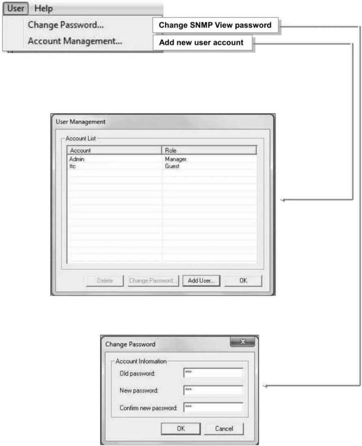
flowchart
graph TD
    A["User Help"] --> B["Change Password..."]
    B --> C["Account Management..."]
    C --> D["Change SNMP View password"]
    D --> E["Add new user account"]
    F["User Management"] --> G["Account List"]
    G --> H["Account"]
    H --> I["Admin"]
    I --> J["ltc"]
    K["Account"] --> L["Role"]
    M["Admin"] --> N["Manager"]
    O["ltc"] --> P["Guest"]
    Q["Delete"] --> R["Change Password..."]
    S["Add User..."] --> T["OK"]
    U["OK"] --> V["Cancel"]
    W["Change Password"] --> X["Account Information"]
    X --> Y["Old password: ****"]
    X --> Z["New password: ****"]
    X --> AA["Confirm new password: ****"]
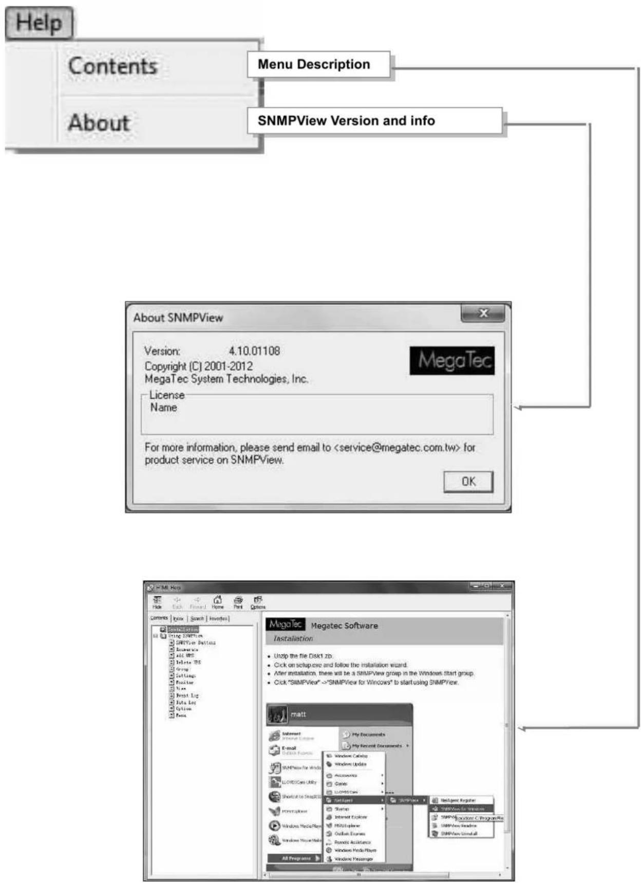
Chapter 8. iMConfig
iMConfig is a tool software that allows user to change the same parameter on multi NetAgent simultaneously.
Installation and setup
iMConfig is available in the CD provided with NetAgent. After installed, it saves under directory of
All Programs > NetAgent> iMConfig

Operation Interface
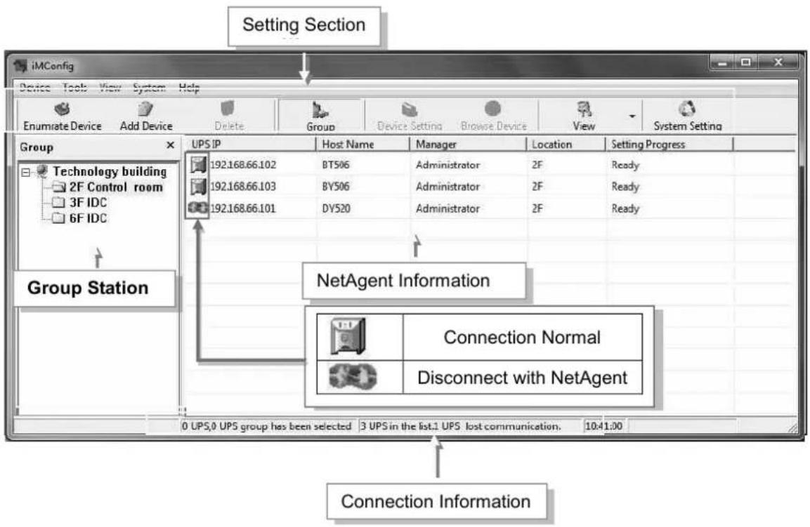
Setting Tab
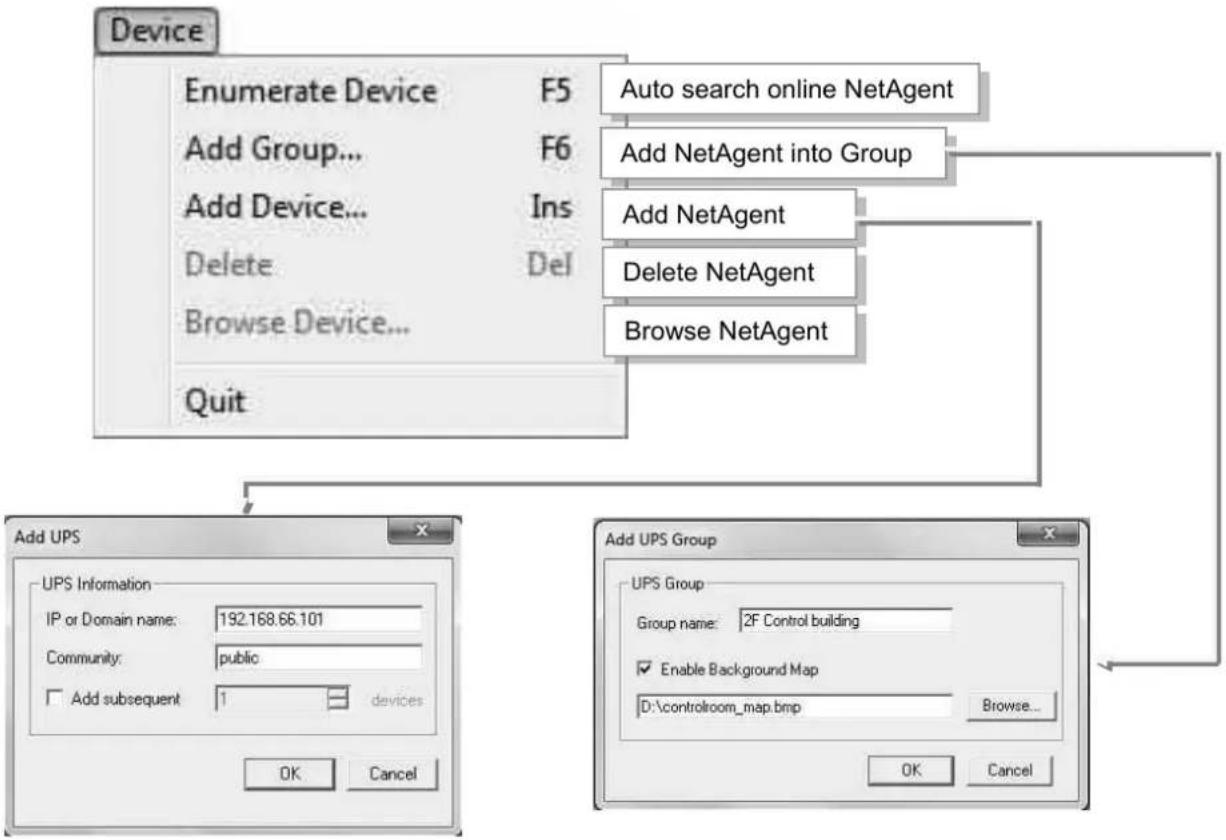
flowchart
graph TD
    A["Device"] --> B["Enumerate Device F5"]
    A --> C["Add Group... F6"]
    A --> D["Add Device... Ins"]
    A --> E["Delete Del"]
    A --> F["Browse Device..."]
    A --> G["Quit"]
    H["Add UPS"] --> I["UPS Information"]
    I --> J["IP or Domain name: 192.168.66.101"]
    I --> K["Community: public"]
    K --> L["Add subsequent 1 devices"]
    M["Add UPS Group"] --> N["Group name: 2F Control building"]
    N --> O["Enable Background Map"]
    O --> P["D:\controlroom_map.bmp Browse..."]
    P --> Q["OK Cancel"]
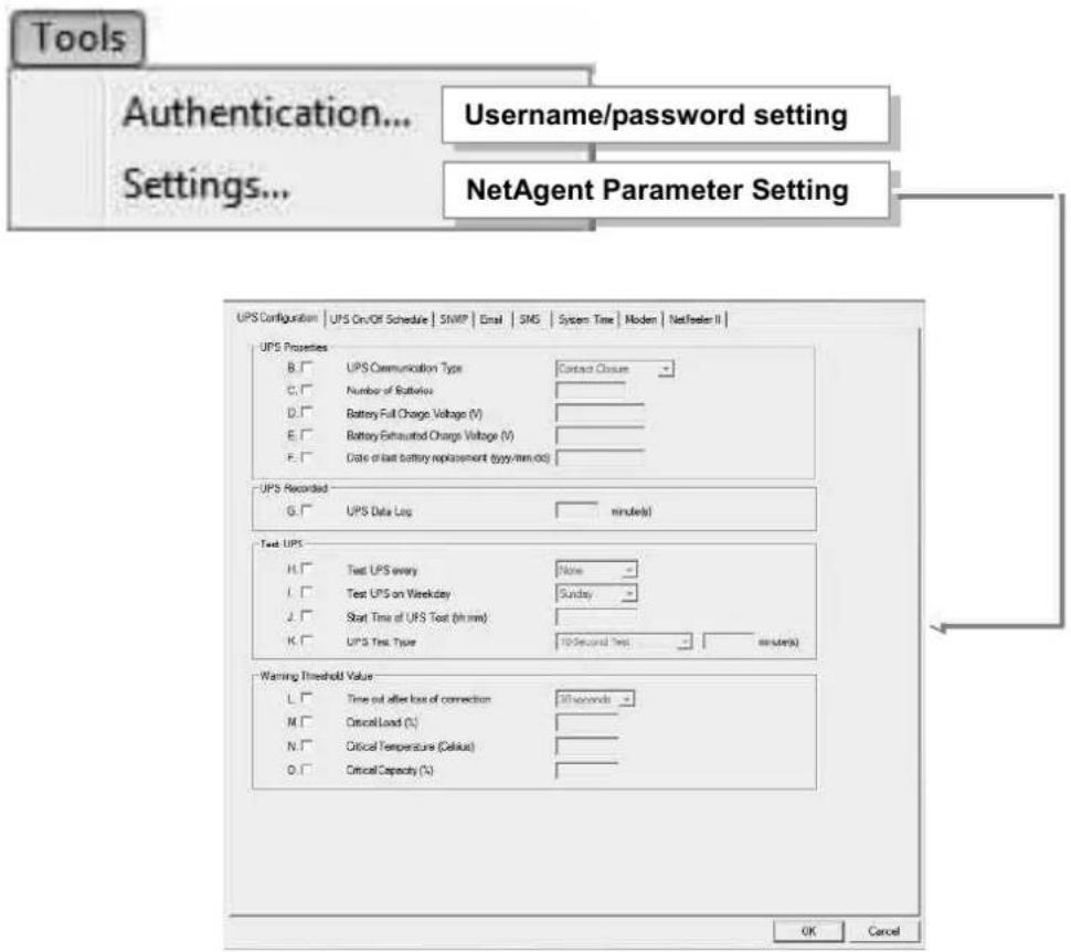
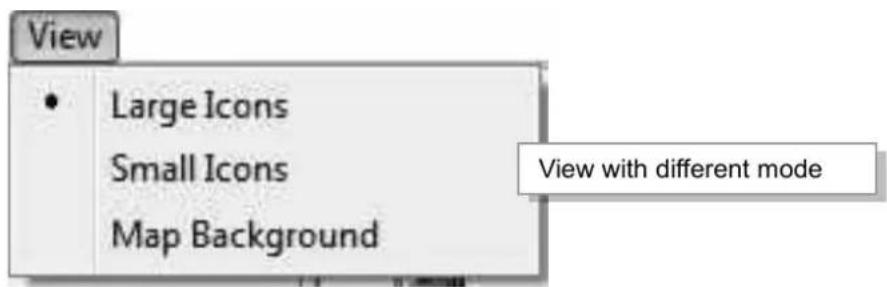
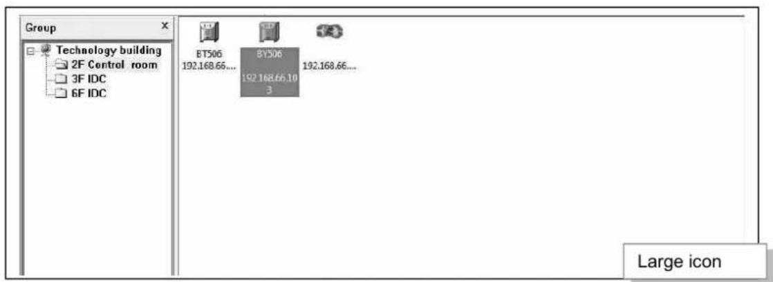
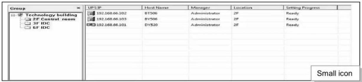
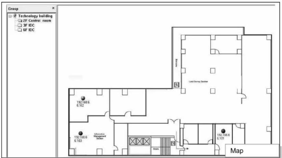
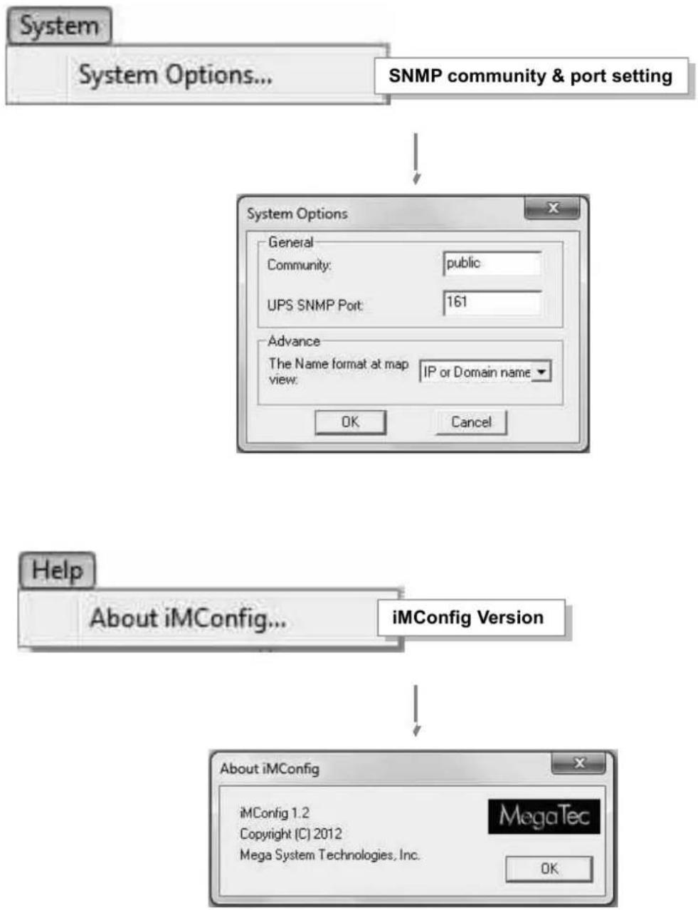
flowchart
graph TD
    A["System Options..."] --> B["SNMP community & port setting"]
    B --> C["System Options"]
    C --> D["General"]
    D --> E["Community: public"]
    E --> F["UPS SNMP Port: 161"]
    F --> G["Advance"]
    G --> H["The Name format at map view: IP or Domain name ▼"]
    H --> I["OK"]
    H --> J["Cancel"]
    K["Help"] --> L["About iMConfig..."]
    L --> M["iMConfig Version"]
    M --> N["About iMConfig"]
    N --> O["iMConfig 1.2"]
    N --> P["Copyright (C) 2012"]
    N --> Q["Mega System Technologies, Inc."]
    N --> R["MegaTec"]
Chapter 9. SMS Server Software
SMS notification can be send by modem that connects to 3 ports NetAgent II or NetAgent 9 (BX/BY) model directly, or, it can also be achieved by the remote PC that has SMS Server software installed with modem connected
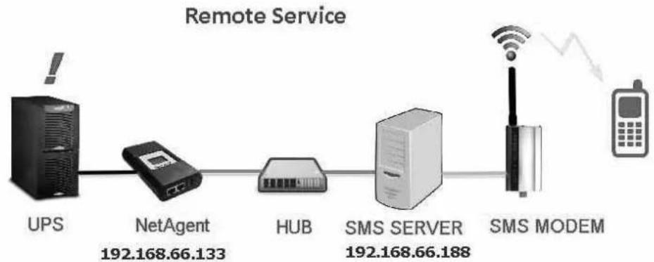
flowchart
graph LR
    A["UPS"] --> B["NetAgent 192.168.66.133"]
    B --> C["HUB"]
    C --> D["SMS SERVER 192.168.66.188"]
    D --> E["SMS MODEM"]
    E --> F["Mobile Phone"]
    style A fill:#000,stroke:#fff,color:#fff
    style B fill:#f9f,stroke:#333
    style C fill:#ccf,stroke:#333
    style D fill:#cfc,stroke:#333
    style E fill:#fcc,stroke:#333
    style F fill:#ffc,stroke:#333
Modem Installation
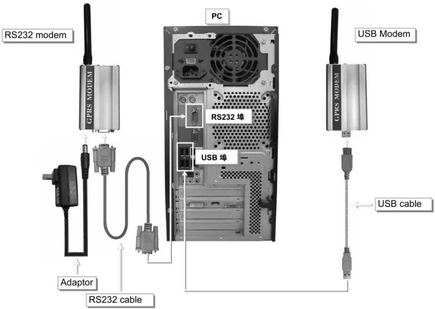
SMS Server Software Installation
SMS Server software is available in the CD provided with NetAgent. After installed, it saves under directory of
All Programs > NetAgent>SMS Server>SMS Server Manager
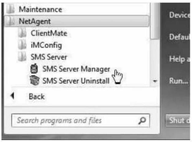
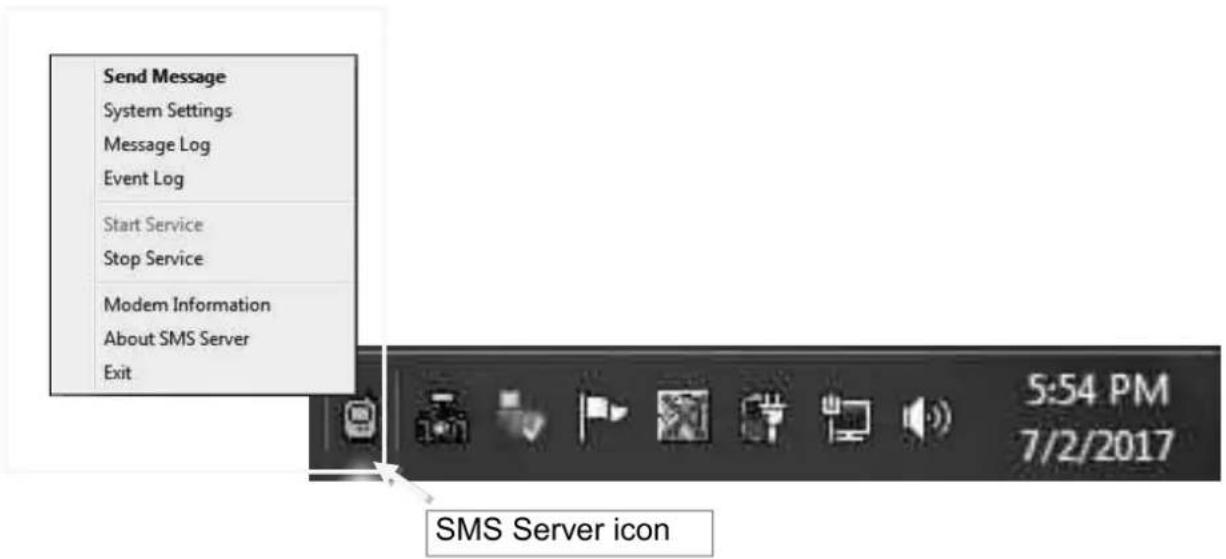
Settings
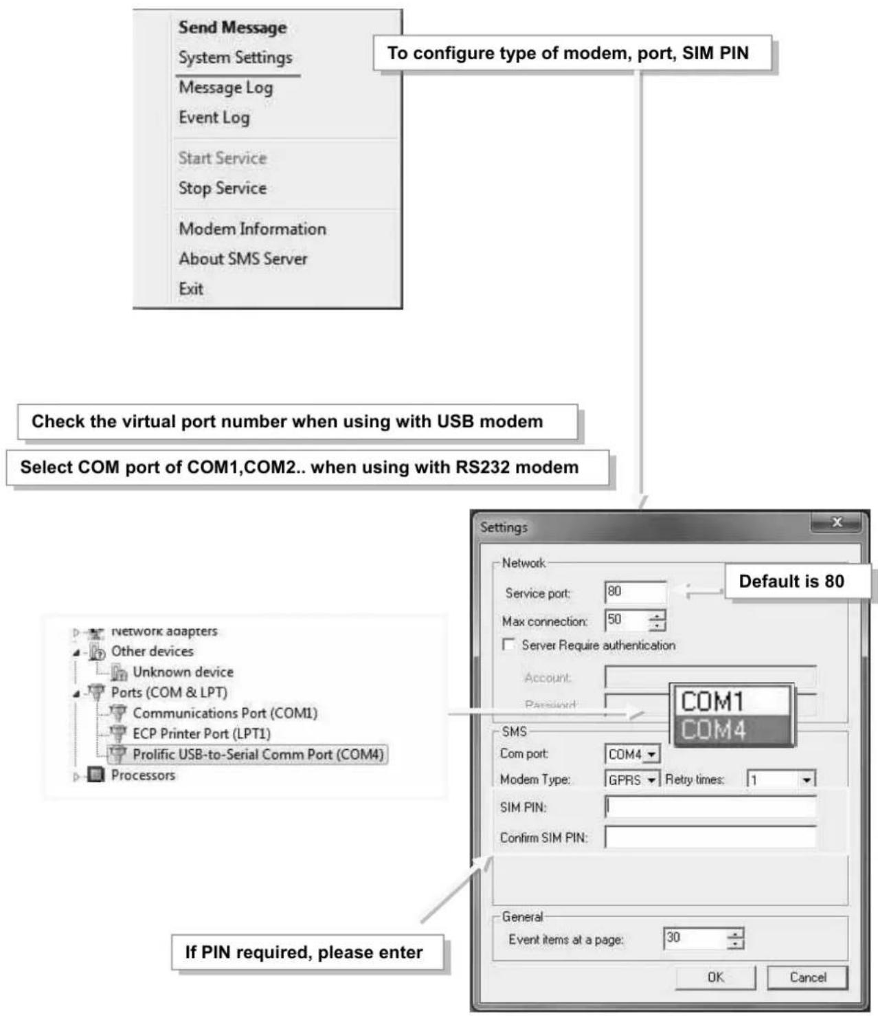
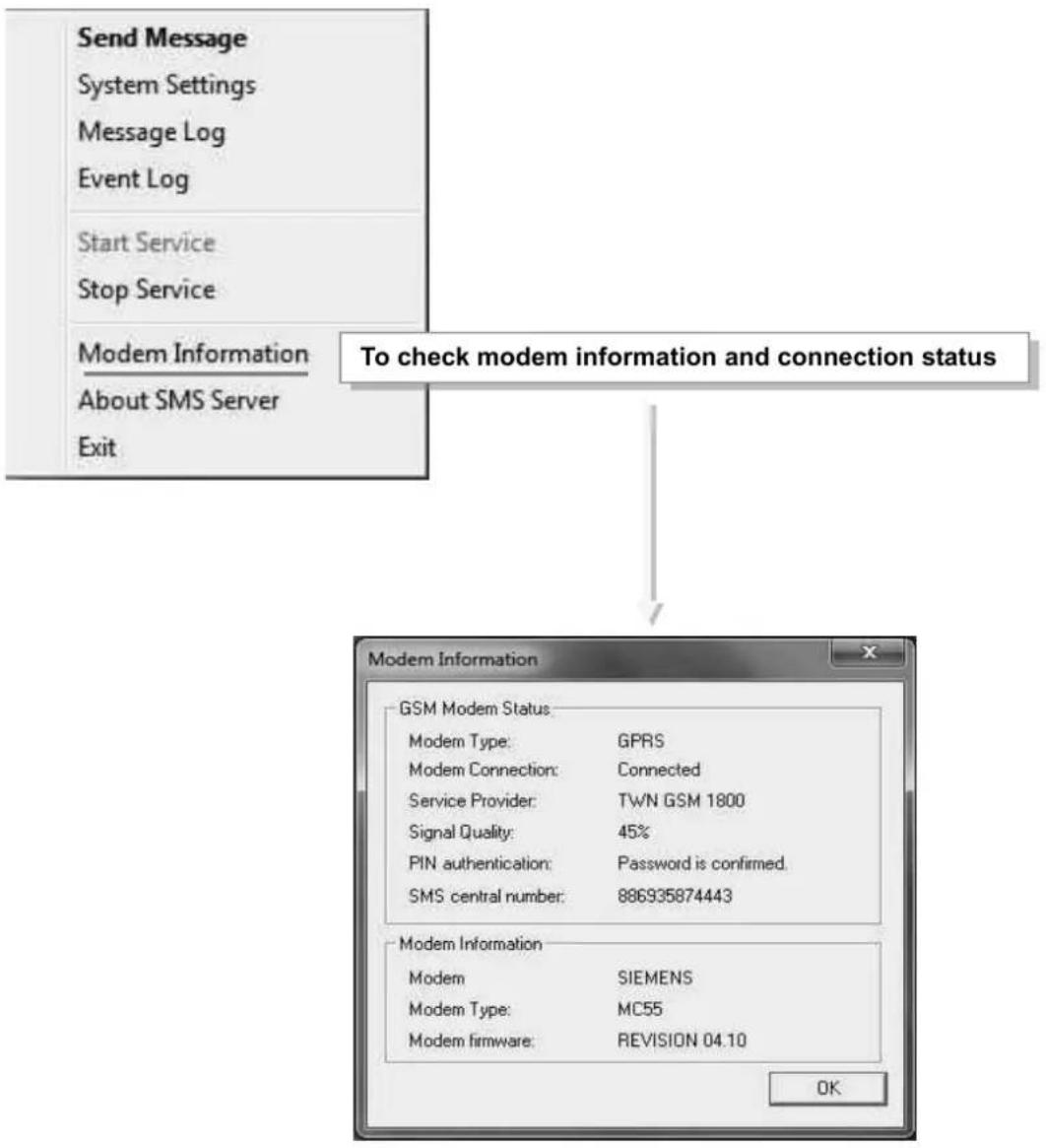
-Ensure all settings are correct and modem is connected with signal in order to send SMS successfully
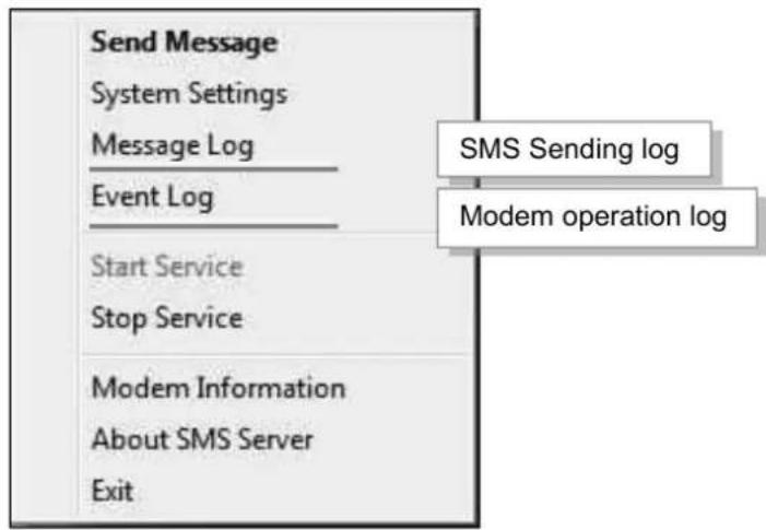
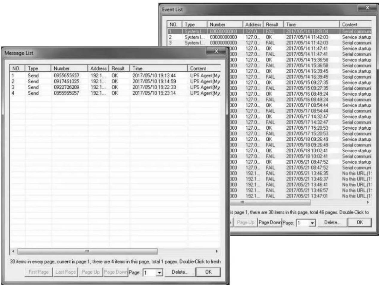
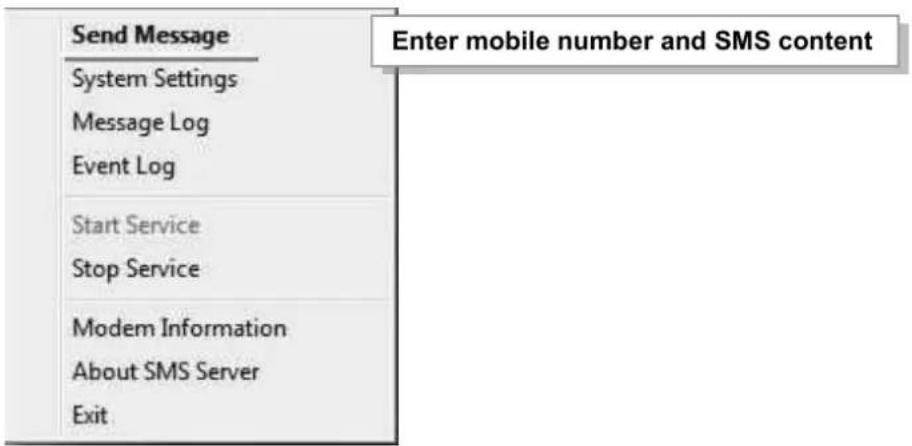
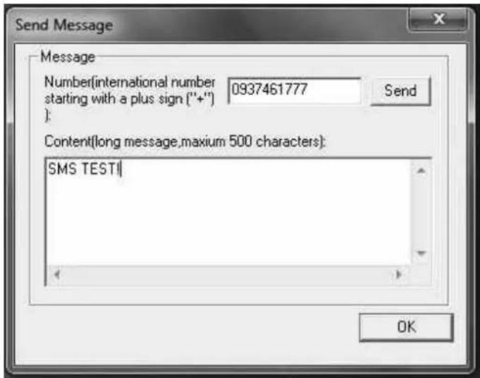
When SMS Server software installation and connection are both complete, the IP address of PC may be entered in the NetAgent's SMS webpage and select "Use Remote Service". Such NetAgent would then be able to send SMS notification via this SMS Server PC
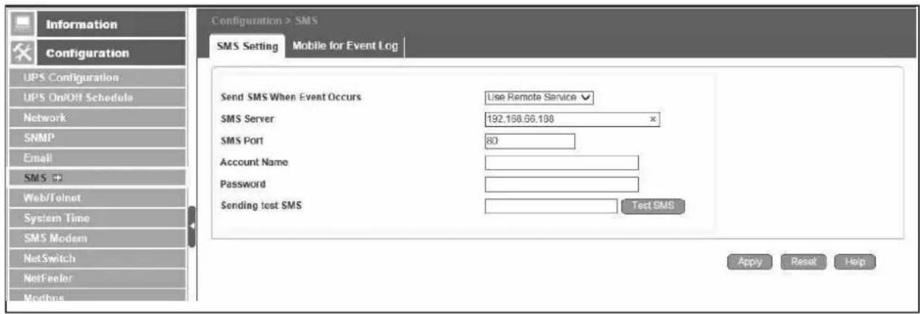
Chapter 10. Appendix
When Netility and NetAgent's username/password are lost, please follow the steps below to clear or check the configuration
- Get the PC that is under same network as NetAgent-SNMP card
- Open up the browser and type http://xxx.xx/password.cgi (xx.xxx is the IP address of the NetAgent)

Password: Enter the master password for the device
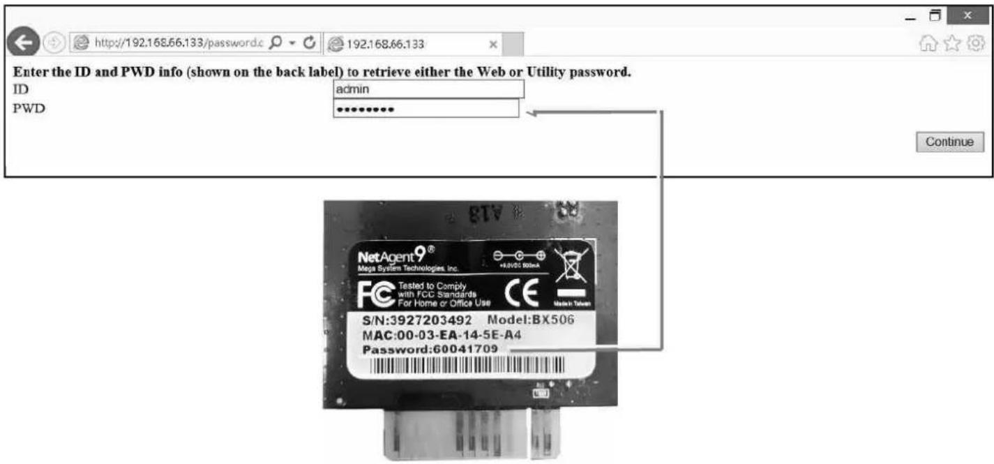
4. Press continue and clear
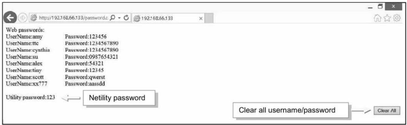

- Technical Support and Contact Information
- Chapter 1. Introduction...... 1
- Chapter 2. NetAgent Series .... 4
- Chapter 3. NetAgent Installation ...... 22
- Chapter 4. NetAgent Setting ...... 26
- Chapter 1. Introduction
- Features
- Features:
- Applications
- ■ NetAgent allows UPS to be monitor on network
- ■ NetAgent Provides Shutdown Utilities
- ■ NetAgent II for Surrounding Monitoring
- Chapter 2. NetAgent Series
- NetAgent Mini
- NetAgent Mini Outlook
- NetAgent Mini LED Indication
- NetAgent II Models
- NetAgent II Outlook
- NetAgent II Led Indication
- NetAgent Mini 9/ NetAgent 9
- NetAgent Mini 9 Models
- NetAgent Mini 9 Outlook
- NetAgent 9 Series
- NetAgent Mini 9 / NetAgent 9 Package Accessories
- Utility CD
- Cables
- Chapter 3. NetAgent Installation
- Hardware Installation
- ■ Internal NetAgent
- ■ External NetAgent Mini
- Software Installation
- Chapter 4. NetAgent Setting
- Introduction
- NetAgent Login Procedure
- Netility Installation and Setting
- Netility Installation
- ■ Netility Operation and Setting
- Online NetAgent List 2. Function Selection
- Online NetAgent List
- Individual NetAgent Info
- Launch Web User Interface
- Network Settings
- Firmware Upgrade
- About
- Refresh List
- NetAgent Setting
- Web Interface
- NetAgent Option Directory Structure
- NetAgent Setting Options
- Network Status
- NetAgent 9 Mini & NetAgent 9
- NetAgent Mini & NetAgent II
- ■ Information > Basic Information
- ■ Information > Current Status
- ■ Information > Remote Control
- ■ Information > Meter/Chart
- ■ Information > SMS Modem Status
- NetAgent 9
- NetAgent II 3 Ports
- ■ Information > NetSwitch Status
- ■ Information > NetFeeler (NetFeeler II)
- NetAgent 9 3PORTS
- ■ Configuration > UPS Configuration
- UPS Communication Type:
- - Test Log
- ● Warning Threshold Values
- ■ Configuration > UPS On/Off Schedule
- - UPS Action
- - Weekly Schedule
- - Date Schedule
- Warning will be initiated before Schedule shutdown event
- - Wake On Lan
- ■ Configuration > Network
- IPv4
- IPv6
- Connection Type
- Stop UPS communication when Ethernet disconnected
- - Dynamic DNS
- Router Configuration
- To change domain name or password, please go to www.icv99.net
- - PPPoE
- ■ Configuration > Wireless
- - Access Control
- Manager IP Address :
- Version:
- Community :
- Permission :
- Description :
- - Trap Notification
- Trap Notification
- Accept :
- Trap Type :
- Severity :
- Events :
- SNMP Inform Request
- ● Device Connected
- Configuration > Email
- ■ Configuration > SMS
- - SMS Setting :
- - Mobile for Event Log
- ■ Configuration > Web/Telnet
- HTTPS Protocols
- SSL Information
- ■ Configuration > System Time
- System Time
- Restart
- ■ Configuration > SMS Modem
- Modem Led Status
- ■ Configuration > NetSwitch
- NetSwitch
- - NetSwitch Settings
- NetSwitchCommunication Port :
- Select NetSwitch :
- Address Change :
- Identification :
- Outlet :
- Name :
- Phone Controllable :
- Control Type :
- Power Off Delay :
- Power Resume Daly :
- ■ Configuration > NetFeeler
- NetFeeler
- NetFeeler :
- Security Label
- ■ Configuration > MODBUS
- ■ Configuration > Language
- Interface Language
- Email Preference
- NetAgent II
- EAST Version
- WEST Version
- ■ Log Information > Event Log
- csv file name as below
- ■ Log Information > SMS Log
- NetAgent II 3PORTS
- ■ Log Information > Data Log
- NetAgent
- Data Log
- Information
- Configuration
- Log Information
- Help
- ■ Log Information > Battery Test Log
- ■ Help > Search NetAgent
- ■ Help > Serial Port Debug
- Port Information
- Sent Information
- Received Information
- ■ Help > Help
- ■ Help > About
- About
- Firmware Update Settings
- Update Firmware from FTP Client
- -Execute ftp + NetAgent's IP address
- -FTP login
- Chapter 5. Telnet/ SSH
- Chapter 6. ClientMate
- Installation and setup
- Close File
- Chapter 7. SNMP View
- Setting Tab/Device
- Device
- Chapter 8. iMConfig
- Operation Interface
- Setting Tab
- Chapter 9. SMS Server Software
- SMS Server Software Installation
- Settings
- Chapter 10. Appendix
- Press continue and clear
Brand : Techly
Model : IUPS-NET504
Category : Network card / adapter