DN-95312 - Switch Digitus - Free user manual and instructions
Find the device manual for free DN-95312 Digitus in PDF.


| Product Type | Network Switch |
| Model | DN-95312 |
| Brand | Digitus |
| Number of Ports | 5 |
| Interface | RJ-45 |
| Speed | 10/100/1000 Mbps |
| Standards | IEEE 802.3, IEEE 802.3u, IEEE 802.3ab, IEEE 802.3x |
| Switching Capacity | 10 Gbps |
| MAC Address Table | 2K |
| Power Supply | External AC/DC adapter (5V, 1A) |
| Dimensions (approx.) | 100 x 75 x 25 mm |
| Weight (approx.) | 150 g |
| Operating Temperature | 0°C to 40°C |
| Storage Temperature | -20°C to 70°C |
| Operating Humidity | 10% to 90% non-condensing |
| Housing Material | Plastic |
| LED Indicators | Power, Link/Act |
| Mounting | Desktop |
| Cooling | Fanless |
| Certification | CE, FCC |
| Package Contents | Switch, power adapter, user manual |
| Maintenance | Clean with dry cloth; avoid liquids |
| Safety | Keep away from moisture and extreme temperatures |
| Spare Parts | Power adapter available as accessory |
Frequently Asked Questions - DN-95312 Digitus
User questions about DN-95312 Digitus
0 question about this device. Answer the ones you know or ask your own.
Ask a new question about this device
Download the instructions for your Switch in PDF format for free! Find your manual DN-95312 - Digitus and take your electronic device back in hand. On this page are published all the documents necessary for the use of your device. DN-95312 by Digitus.
USER MANUAL DN-95312 Digitus
natural_image
Black network switch device with indicator lights and ports (no readable text or symbols)24-PORT 10/100MBPS + 2G COMBO
PoE WEB SMART ETHERNET SWITCH

natural_image
Black network switch device with multiple Ethernet ports and indicator lights (no visible text or labels)Manual
DN-95312 · DN-95313
Table of Content
Chapter 1 Product Introduction ...... 3
1.1 Product Overview ...... 3
1.2 Features ....3
1.3 External Component Description....3
1.3.1 Front Panel....3
1.3.2 Rear Panel 4
1.3.3 LED Indicator Specification....5
1.4 Environment 6
1.5 Package Contents ....7
Chapter 2 Installing and Connecting the Switch .... 8
2.1 Installation 8
2.1.1 Desktop Installation....8
2.1.2 Rack-mountable Installation in 19-inch Cabinet....8
2.1.3 Power on the Switch....9
2.2 Connect Computer (NIC) to the Switch....10
2.3 Switch connection to the PD....10
Chapter 3 How to Login the Switch .... 11
3.1 Switch to End Node 11
3.2 How to Login the Switch....11
Chapter 4 Switch Configuration.... 13
4.1 Administrator 13
4.1.1 Authentication configuration .... 13
4.1.2 System IP Configuration....13
4.1.3 System status....13
4.1.4 Load default setting 14
4.1.5 Firmware update....14
4.1.6 Reboot device....15
4.2 POE....16
4.2.1 POE Status....16
4.2.2 POE Setting....16
4.2.3 PoE Power Delay 17
4.2.4 PoE Scheduling....17
4.2.5 NTP Setting 17
4.3 Port Management....18
4.3.1 Port configuration .... 18
4.3.2 Port mirroring....19
4.3.3 Bandwidth Control 19
4.3.4 Broadcast Storm Control ....20
4.4 VLAN Setting 20
4.4.1 VLAN mode 20
4.4.2 VLAN Member Setting....21
4.4.3 Multi-to-1 Setting ......22
4.5 Per Port Counter....23
4.6 QoS Setting 23
4.6.1 Priority mode ....23
4.6.2 Port, 802.1p, IP/DS based....24
4.6.3 TCP/UDP Port Based 24
4.7 Security....24
4.7.1 MAC Address Binding .....24
4.7.2 TCP/UDP Filter 25
4.8 Spanning Tree 26
4.8.1 STP Bridge Settings 26
4.8.2 STP Port Settings....26
4.8.3 Loopback Detection....27
4.9 Trunking....28
4.10 DHCP Relay Agent....29
4.10.1 DHCP Relay Agent....29
4.10.2 Relay Server....29
4.10.3 VLAN MAP Relay Agent....29
4.11 Backup/Recovery ......29
4.12 Miscellaneous....30
4.13 SNMP Settings .... 31
4.14 Logout....31
Appendix: Technical Specifications 32
Chapter 1 Product Introduction
Congratulations on your purchasing of DIGITUS PoE Web Smart Ethernet Switch. Before you install and use this product, please read this manual carefully for full exploiting the functions of this product.
1.1 Product Overview
The 10/100Mbps PoE Web Smart Ethernet Switch provides the seamless network connection. It integrates 100Mbps Fast Ethernet and 10Mbps Ethernet network capabilities.
These POE ports can automatically detect and supply power with those IEEE 802.3at compliant Powered Devices (PD). In this situation, the electrical power is transmitted along with data in one single cable allowing you to expand your network where there are no power lines or outlets, where you wish to fix devices such as AP, IP Cameras or IP Phones, etc.
The Switch may carry on the management and the condition monitoring through the network management software to the POE power supply function, may demand opens or the closure port POE power supply function willfully, provides the port power supply priority management, the 10/100M POE Switch is a great selection for expanding your home or office network.
1.2 Features
1-16/24port support POE
➢ Supports PoE power up to 30W for each PoE port
➢ Supports power up to 260W/330W
Supports PoE IEEE802.3at compliant PDs
Supports IEEE802.3x flow control for Full-duplex Mode and backpressure for Half-duplex Mode
➢ 4K entry MAC address table with auto-learning and auto-aging
➢ LED indicators for monitoring power, link, activity and speed
▶ Internal power supply
1.3 External Component Description
1.3.1 Front Panel
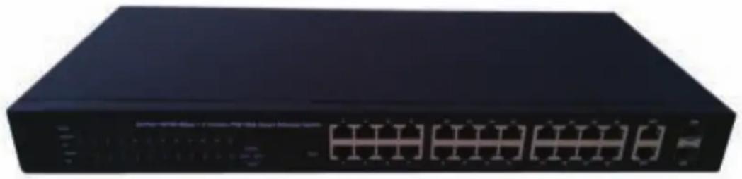
The front panel of the Switch consists of series of LED indicators, 24 10/100Mbps RJ-45 ports, 2 10/100/1000Mbps RJ-45 ports and 2 SFP ports a shown as below.
natural_image
Front view of a black networking device with multiple ports and indicator lights (no visible text or labels)Figure 1 - Front Panel
10/100Mbps RJ-45 ports (1\~24):
Designed to connect to the device with a bandwidth of 10Mbps or 100Mbps. Each has a corresponding 10/100Mbps LED.
10/100/1000Mbps RJ-45 ports (25T, 26T):
Designed to connect to the device with a bandwidth of 10Mbps, 100Mbps or 1000Mbps. Each shares a corresponding LED with an associated SFP port.
SFP ports (25S, 26S):
Designed to install the SFP module. The Switch features two SFP transceiver slots that are shared with two associated RJ45 ports. A SFP port and an associated RJ45 port are referred to as “Combo” port, which means they cannot be used simultaneously, and only SFP port work or only RJ45 port work at the same time.
Reset:
Keep the device powered on and push a paper clip into the hole. Press down the button for about 2 seconds. The system restores the factory default settings.
1.3.2 Rear Panel
The rear panel of the Switch contains AC power connector shown as below.

natural_image
Front view of a black electronic device with ports and indicator lights (no visible text or symbols)Figure 2 - Rear Panel
AC Power Connector:
Power is supplied through an external AC power adapter. It supports AC 100 \~ 240V, 50 / 60Hz.
Grounding Terminal:
The Switch already comes with Lightning Protection Mechanism. You can also ground the Switch through the PE (Protecting Earth) cable of AC cord or with Ground Cable.
1.3.3 LED Indicator Specification
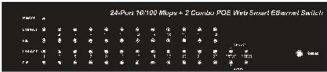
The LED indicators of the Switch contain one Power, 26 LINK/ACT, 24 PoE status and 2 Speed. The LED Indicators will allow you to monitor, diagnose and troubleshoot any potential problem with the Switch, connection or attached devices.
text_image
24-Port 10:100 Mups + 2 Combo POE Web Smart Ethernet Switch PORT L1896.1 12 13 14027 1 2 3 4 5 6 7 8 9 10 11 12 13 14 15 16 17 18 19 20 21 22 23 24 IP/O IP/O IP/O IP/O IP/O IP/O IP/O IP/O IP/O IP/O IP/O IP/O IP/O IP/O IP/O IP/O IP/O IP/O IP/O IP/O IP/O IP/O IP/O IP/O IP/O IP/O IP/O IP/O IP/O IP/O IP/O IP/O IP/O IP/OFigure 3 - LED Indicators
The following chart shows the LED indicators of the Switch along with explanation of each indicator.
| LED COLOR STATUS | STATUS | DESCRIPTION | |
| Power | Green | On | Power |
| Off | Power | ||
| LINK/ACT(1~24) | Green | On A device is connected to the port | |
| Off A device is disconnected to the port | |||
| Flashing Sending or receiving data | |||
| 25, 26T/S | LINK/ACT Green | On A device is connected to the port | |
| Off A device is disconnected to the port | |||
| Flashing Sending or receiving data | |||
| Speed Green | On A 1000Mbps device is connected to the port | ||
| Off A 10Mbps device is connected to the port | |||
| Flashing A 100Mbps device is connected to the port | |||
| POE | Orange | On | A Powered Device is connected to the port, which supply power successfully. |
| Off | No Powered Device connected to the port, or no power is supplied according to the power limits of the port. | ||
| Flashing | The POE power circuit may be in short or the power current may be overloaded. | ||
1.3.4 Front Panel
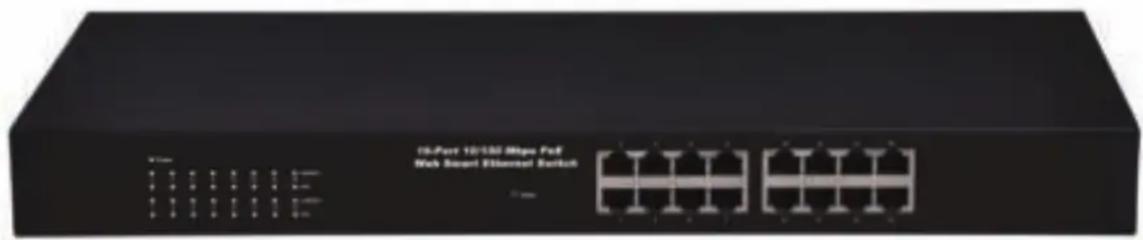
The front panel of the Switch consists of series of LED indicators and 16 10/100Mbps RJ-45 ports.
text_image
15-Port 10/130 Mbps FoF Web Mount Ethernet SwitchFigure 1 - Front Panel
10/100Mbps RJ-45 ports (1\~16):
Designed to connect to the device with a bandwidth of 10Mbps or 100Mbps. Each has a corresponding 10/100Mbps LED.
Reset:
Keep the device powered on and push a paper clip into the hole. Press down the button for about 2 seconds. The system restores the factory default settings.
1.3.5 Rear Panel
The rear panel of the Switch contains AC power connector shown as below.

natural_image
Front view of a black electronic device with ports and indicator lights (no visible text or symbols)Figure 2 - Rear Panel
AC Power Connector:
Power is supplied through an external AC power adapter. It supports AC 100 \~ 240V, 50 / 60Hz.
Grounding Terminal:
The Switch already comes with Lightning Protection Mechanism. You can also ground the Switch through the PE (Protecting Earth) cable of AC cord or with Ground Cable.
1.3.6 LED Indicator Specification
The LED indicators of the Switch contain one Power, 26 LINK/ACT, 24 PoE status and 2 Speed. The LED Indicators will allow you to monitor, diagnose and troubleshoot any potential problem with the Switch, connection or attached devices.

text_image
Power 2 4 6 8 10 12 14 16 ● ● ● ● ● ● ● ● ● ● ● ● ● ● ● ● ● ● ● ● ● ● ● ● ● ● 1 3 5 7 9 11 13 15 ● ● ● ● ● ● ● ● ● ● LNKACT PuE ● LNKACT PuEFigure 3 - LED Indicators
The following chart shows the LED indicators of the Switch along with explanation of each indicator.
| LED COLOR STATUS | DESCRIPTION | ||
| Power | Green | On | Power |
| Off | Power | ||
| LINK/ACT(1~16) | Green | On A device is connected to the port | |
| Off A device is disconnected to the port | |||
| Flashing Sending or receiving data | |||
| POE | Orange | On | A Powered Device is connected to the port,which supply power successfully. |
| Off | No Powered Device connected to the port, orno power is supplied according to the powerlimits of the port. | ||
| Flashing | The POE power circuit may be in short or thepower current may be overloaded. | ||
1.4 Environment
Operating Temperature: 0°C\~40°C
Storage Temperature: -10°C\~70°C
➢ Operating Humidity: 10%\~90% non-condensing
➢ Storage humidity: 5%\~90% non-condensing
1.5 Package Contents
One POE Web Smart Ethernet Switch
➢ Four rubber feet, two mounting ears and eights screws
One AC power cord
One User Manual
Chapter 2 Installing and Connecting the Switch
This part describes how to install your Ethernet Switch and make connections to it. Please read the following topics and perform the procedures in the order being presented.
2.1 Installation
Please follow the following instructions in avoid of incorrect installation causing device damage and security threat.
➢ Put the Switch on stable place or desktop in case of falling damage.
Make sure the Switch works in the proper AC input range and matches the voltage labeled on the Switch.
To keep the Switch free from lightning, do not open the Switch's shell even in power failure.
Make sure that there is proper heat dissipation from and adequate ventilation around the Switch.
Make sure the cabinet to enough back up the weight of the Switch and its accessories.
2.1.1 Desktop Installation
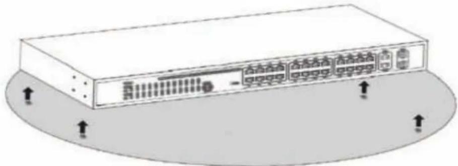
Sometimes users are not equipped with the 19-inch standard cabinet. So when installing the Switch on a desktop, please attach these cushioning rubber feet provided on the bottom at each corner of the Switch in case of the external vibration. Allow adequate space for ventilation between the device and the objects around it.
natural_image
Illustration of a network device with ports and connectors, no text or symbols presentFigure 4 - Desktop Installation
2.1.2 Rack-mountable Installation in 19-inch Cabinet
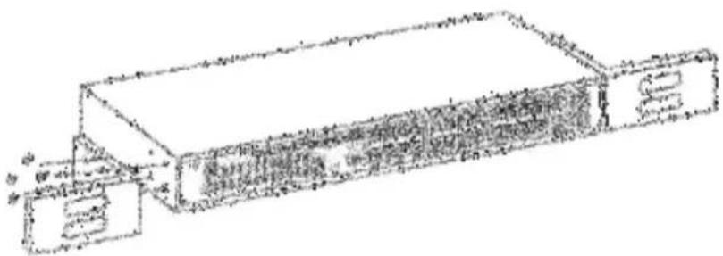
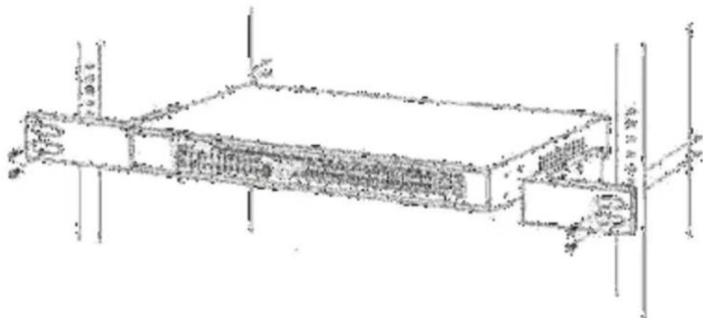
The Switch can be mounted in an EIA standard-sized, 19-inch rack, which can be placed in a wiring closet with other equipment. To install the Switch, please follow these steps:
- Attach the mounting brackets on the Switch's side panels (one on each side) and secure them with the screws provided.
natural_image
Technical line drawing of a mechanical component or housing (no text or symbols visible)Figure 5 - Bracket Installation
- Use the screws provided with the equipment rack to mount the Switch on the rack and tighten it.
natural_image
Technical line drawing of a mechanical assembly with no visible text or symbolsFigure 6 - Rack Installation
2.1.3 Power on the Switch
The Switch is powered on by the AC 100 \~ 240V 50 / 60Hz internal high-performance power supply. Please follow the next tips to connect:
AC Electrical Outlet:
It is recommended to use single-phase three-wire receptacle with neutral outlet or multifunctional computer professional receptacle. Please make sure to connect the metal ground connector to the grounding source on the outlet.
AC Power Cord Connection:
Connect the AC power connector in the back panel of the Switch to external receptacle with the included power cord, and check the power indicator is ON or not. When it is ON, it indicates the power connection is OK.
2.2 Connect Computer (NIC) to the Switch
Please insert the NIC into the computer, after installing network card driver, please connect one end of the twisted pair to RJ-45 jack of your computer, the other end will be connected to any RJ-45 port of the Switch, the distance between Switch and computer is around 100 meters. Once the connection is OK and the devices are power on normally, the LINK/ACT status indicator lights corresponding ports of the Switch.
2.3 Switch connection to the PD
1-16/24 ports of the Switch have POE power supply function, the maximum output power up to 30W each port, it can make PD devices, such as internet phone, network camera, wireless access point work. You only need to connect the Switch POE port directly connected to the PD port by network cable.
Chapter 3 How to Login the Switch
3.1 Switch to End Node
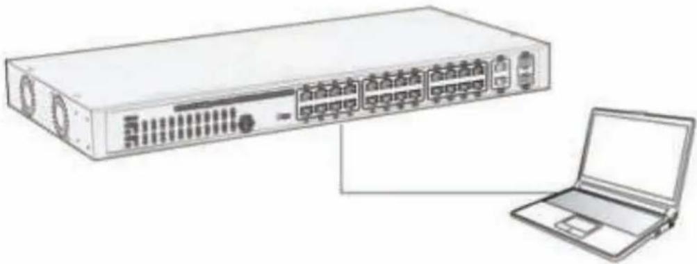
Use standard Cat.5/5e Ethernet cable (UTP/STP) to connect the Switch to end nodes as described below. Switch ports will automatically adjust to the characteristics (MDI/MDI-X, speed, duplex) of the device to which is connected.
natural_image
Illustration of a network switch device connected to a laptop (no text or symbols visible)Please refer to the LED Indicator Specification. The LINK/ACT LEDs for each port lights green when the link is available.
3.2 How to Login the Switch
As the Switch provides Web-based management login, you can configure your computer's IP address manually to log on to the Switch. The default settings of the Switch are shown below.
| Parameter Default Value | |
| Default IP address 192.168.2.1 | |
| Default user name admin | |
| Default password admin | |
You can log on to the configuration window of the Switch through following steps:
- Connect the Switch with the computer NIC interface.
- Power on the Switch.
- Check whether the IP address of the computer is within this network segment: 192.168.2.xxx ("xxx" ranges 2\~254), for example, 192.168.2.100.
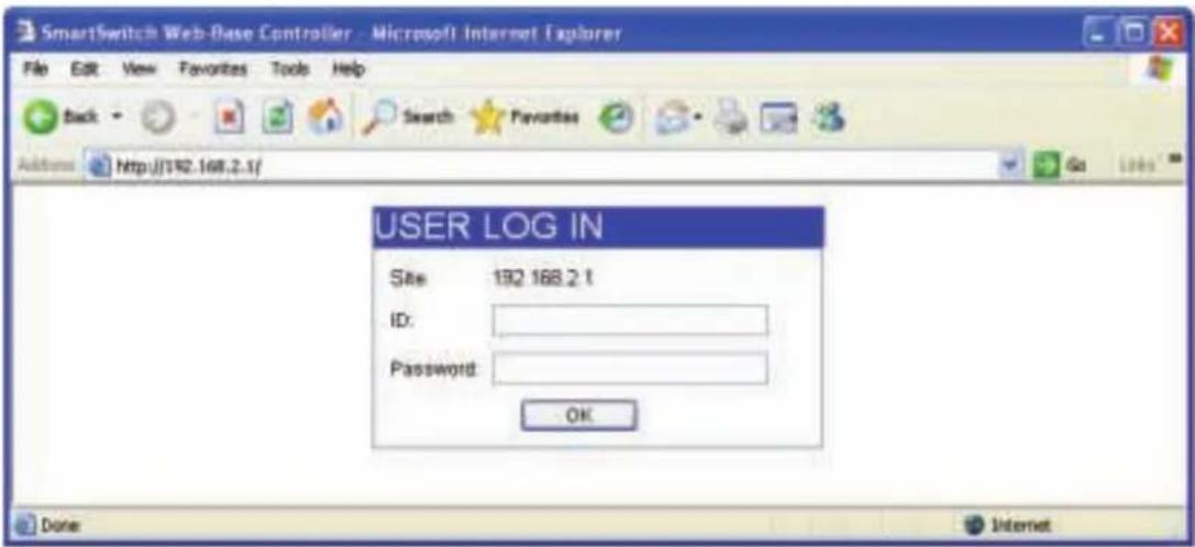
- Open the browser, and enter http://192.168.2.1 and then press "Enter". The Switch login window appears, as shown below.
text_image
SmartSwitch Web-Base Controller - Microsoft Internet Explorer File Edit View Favorites Tools Help Back Search Favorites Address Http://192.168.2.1/ USER LOG IN Site: 192.168.2.1 ID: Password: OK Done Internet- Enter the ID and Password (The factory default login ID is admin and Password is admin), and then click "OK" to log in to the Switch configuration window as below.
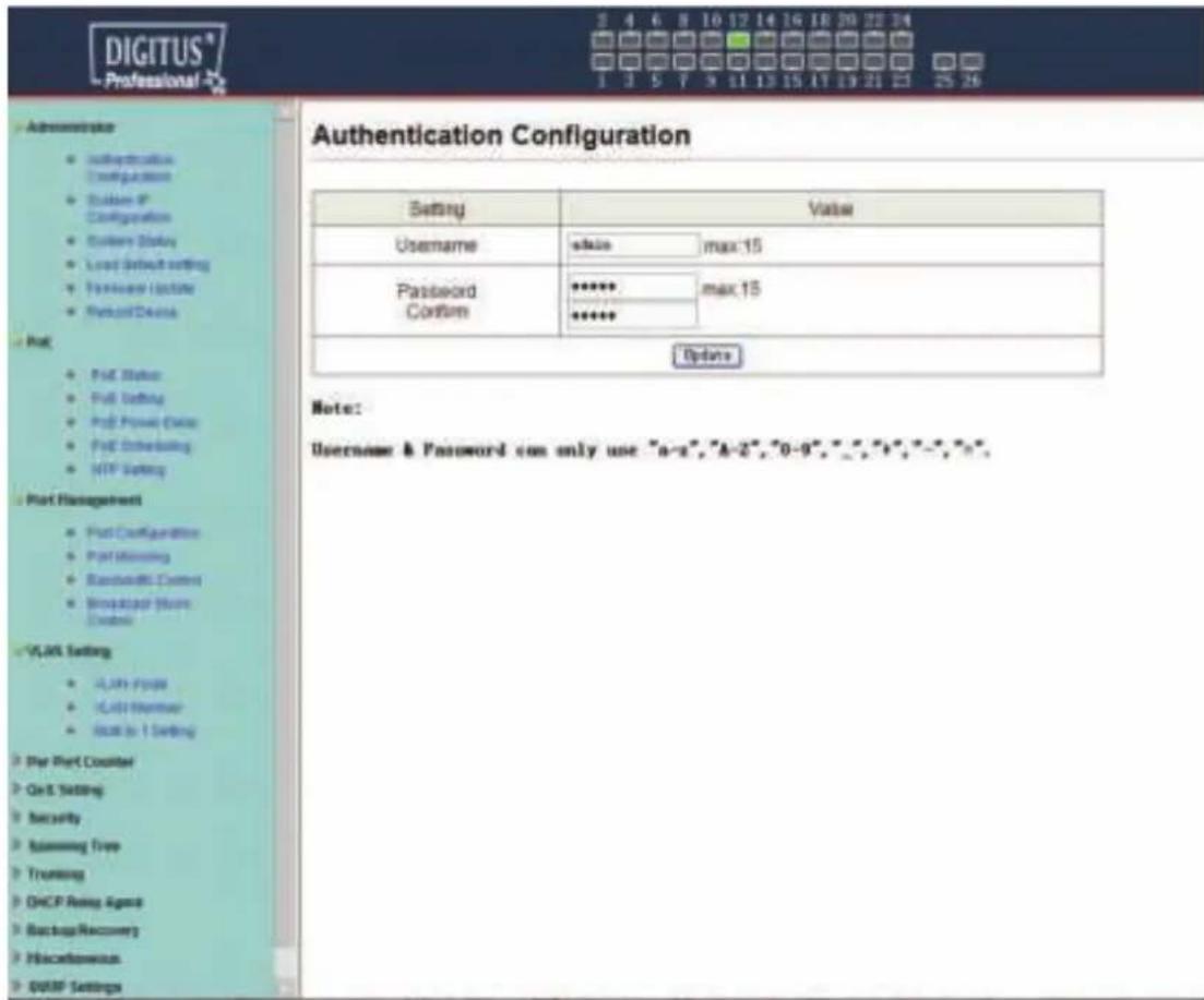
text_image
DIGITUS® Professional 2 4 6 8 10 12 14 16 18 20 22 24 1 3 5 7 9 11 13 15 17 19 21 23 25 26 Authentication Configuration Authentication Configuration Customs ID Configuration System Debug Load Setup setting Transcript Update Remove Device Post: Post Status Post Setting Post Power Data Post Scheduling NIP Setting Part Management Part Configuration Part Monitoring Randomize Control Microsoft Home Options VLAN Setting A-Link Page C-Link Manager Back to 1 Setting Par Port Counter Car Set Setting Security Assuming Tree Trucking DHCP Running Agent Backup Recovery Miscellaneous DUP Settings Authentication Configuration Username value max:15 Password ***** max:15 Confirm ***** Update Note: Username & Password can only use "a-a", "A-2", "0-9", "*, *", **, **, **, **, **, **, **, **, **, **, **, **, **, **, **, **, **, **, **, **, **, **, **, **, **, **, **, **, **, **, **, **, **, **, **, **, **, **, **, **, **, **, **, **, **, **, **, **, **, **, *%,(24-port version view)
In the Web GUI, the left column shows the configuration menu and the rest of the screen area displays the configuration settings.
Chapter 4 Switch Configuration
4.1 Administrator
4.1.1 Authentication configuration
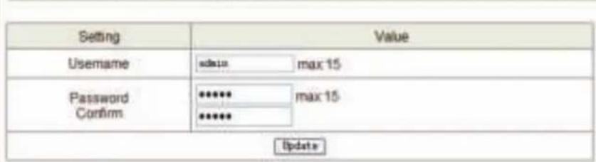
Authentication Configuration diagram box allows user to modify Username and Password, and then enter new username and password. After completing, press "Update" button to take effect.
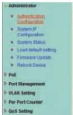
text_image
Administrator • Authentication Configuration • System IP Configuration • System Status • Least default setting • Firmware Update • Rabbit Claims • Port • Port Management • VLAN Setting • Per Port Courier • GoS SettingAuthentication Configuration
text_image
Setting Value Username admin[max 15] Password ******** max 15 Confirm ******** UpdateNote:
Username & Password can only use "a-z", "A-Z", "0-9", "_", "+", "-", *=.
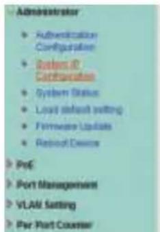
4.1.2 System IP Configuration
This page shows system configuration including the current IP Address and Subnet Mask, Gateway, and IP Configure.
text_image
Administrator • Authentication Configuration • Systems ID Characteristics • System Status • Local default setting • Firmware Updates • Reset Device • Port Management • VLAN Setting • Per Port CounterSystem IP Configuration
| Setting | Value |
| IP Address | 192, 168, 2, 1 |
| Subnet Bank | 258, 246, 258, 0 |
| Gateway | 192, 168, 2, 254 |
| IP Configure | Static O DHCP |
| Update | |
IP Address, Subnet Mask, and Gateway at system IP Configuration diagram box can be configured by user. The Switch also supports DHCP methods to get IP address from DHCP server.
4.1.3 System status
This page is used to check the status of the Switch, including the switch MAC address and software version.

text_image
System Status MAC Address 10:00-12:00-18:26 Number of Ports 24x2 Comment Install 30A/15 System Version 20131132_vIP1926D_PoGPD68108_1986-01 Idle Time Security side Time (t): 7-10 minutes) Auto Logout(Default) Sack for the last dropouts Scales Note: Comment name only can use "a" or "b" as a "c" in the system.The MAC address and version of the Switch will be shown at system status diagram box. Comment field can accept "a-z", "A-Z", "0-9", "_", "+", "-", "=", excluding special character.
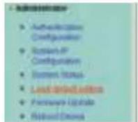
4.1.4 Load default setting
Clicking the "Load" button will make the switch being set to the original configuration.

text_image
Load Default Setting recover switch default setting excluding the IP address. User name and Password LoadWhen Load Default is executed, the all settings will be restored to default setting. Press "Load" button at load default setting page, and then the process of the load default setting will be executed. Press "Reboot" button to take effect.

Please click "Start" to use now existing to order.
After completing load default procedure, IP address, user name and password will keep original setting.
4.1.5 Firmware update
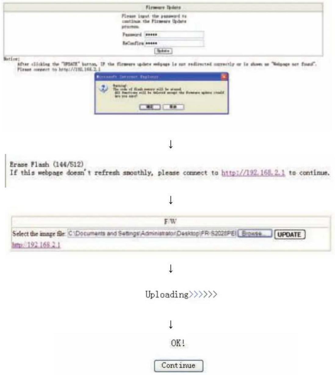
After pressing "Update" button, the Switch will erase the older version flash code first. Then enter file name at specific path, and the update will be completed.
Using default IP to execute firmware update process:

text_image
Filemark Update Filemark Input the password to continue the Filemark Update previces. Password: Sendfile Before: After utilizing the "SPONS" button, if the Filemark Update will page is not validated correctly or to above as "Wpage not found". Please connect to http://100.000.5.1Enter password to execute firmware update process. After pressing "Update" button, the old web code will be erased. After completing, select the image file and enter update button to take effect.
text_image
Firmware Update Please import the password to continue the Firmware Update process. Password ****** ReConfirm ****** Update Notice: After clicking the "UPDATE" button, IF the Firmware update webpage is not redirected correctly or is shown as "Webpage not fixed". Please connect to http://192.168.2.1 Microsoft's Internet Explorer Opening The order of flash memory will be stored. 402 Functions still be deleted except the Firmware Update (which are you sure)? 确定 取消 Erase Flash (144/S12) If this webpage doesn't refresh smoothly, please connect to http://192.168.2.1 to continue. F/W Select the image file: C:\Documents and Settings\Administrator\Desktop\FR-S2028PE Browse UPDATE http://192.168.2.1 Uploading>>>>> OK! Continue4.1.6 Reboot device
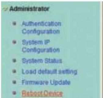
This page is used to reboot device.
Press "Confirm" button to take effect for rebooting device.
text_image
Administrator • Authentication Configuration • System IP Configuration • System Status • Load default setting • Firmware Update • Reboot Device
text_image
Reboot Device: Click "Confirm" to Reboot the Device Confirm4.2 POE
4.2.1 POE Status
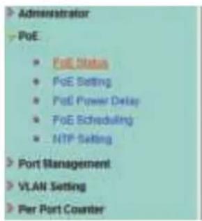
This page is used to check POE Status, you can set Max Available Power here.
text_image
Administrator PoE • PoE Status • PoE Setting • PoE Power Delay • PoE Scheduling • NTP Setting Port Management VLAN Setting Per Port CounterPoE Status
| Max available Power | 500 Watt Update |
| System operation status | On |
| Main Power consumption | 0(Matt) |
| Device Temperature | |
| Device #1 | 36 (C) |
| Device #2 | 38 (C) |
| Device #3 | 39 (C) |
4.2.2 POE Setting
This page is for PoE setting.

text_image
Administrator • Proc • Proc Status • Proc Setting • Proc Power States • Proc Subnetworking • MTP Setting • Port Management • VLAN Setting • Par Port Counter • Gait Setting • Security • Accounting Tree • Training • DHCP Relay Agent • Backup Recovery • Rhacorobics • SNMP Settings • LognetPoE Setting
| Function | Status | Priority | Power Budget |
| (Critical-1, High-2, Low-3) | (Matt MAX:36W) | ||
| Port No. | 01 □ 02 □ 03 □ 04 □ 05 □ 06 □ 07 □ 08 □ 09 □ 10 □ 11 □ 12 □13 □ 14 □ 15 □ 16 □ 17 □ 18 □ 19 □ 20 □ 21 □ 22 □ 23 □ 24 □ | ||
| Update | |||
| Port Status Refresh | |||||
| Port | Status | Class | Priority | Power Consumption(Watt) | Power Budget(Watt) |
| 1 | Enable | — | 3 | 0.00 | 30 |
| 2 | Enable | — | 3 | 0.00 | 30 |
| 3 | Enable | — | 3 | 0.00 | 30 |
| 4 | Enable | — | 3 | 0.00 | 30 |
| 5 | Enable | — | 3 | 0.00 | 30 |
| 6 | Enable | — | 3 | 0.00 | 30 |
| 7 | Enable | — | 3 | 0.00 | 30 |
| 8 | Enable | — | 3 | 0.00 | 30 |
| 9 | Enable | — | 3 | 0.00 | 30 |
| 10 | Enable | — | 3 | 0.00 | 30 |
| 11 | Enable | — | 3 | 0.00 | 30 |
| 12 | Enable | — | 3 | 0.00 | 30 |
| 13 | Enable | — | 3 | 0.00 | 30 |
| 14 | Enable | — | 3 | 0.00 | 30 |
| 15 | Enable | — | 3 | 0.00 | 30 |
| 16 | Enable | — | 3 | 0.00 | 30 |
| 17 | Enable | — | 3 | 0.00 | 30 |
| 18 | Enable | — | 3 | 0.00 | 30 |
| 19 | Enable | — | 3 | 0.00 | 30 |
| 20 | Enable | — | 3 | 0.00 | 30 |
| 21 | Enable | — | 3 | 0.00 | 30 |
| 22 | Enable | — | 3 | 0.00 | 30 |
| 23 | Enable | — | 3 | 0.00 | 30 |
| 24 | Enable | — | 3 | 0.00 | 30 |
Status: Enable or disable the specified function.
Priority: Setting the priority of POE.
4.2.3 PoE Power Delay
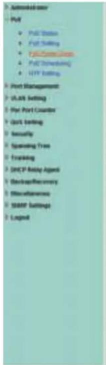
This page is for setting PoE Power Delay.
text_image
• Automated user • Part • Part Setting • User Setting • Part Description • User Setting • User Setting • Start Management • User Setting • Part Port Counter • Start Setting • Security • Spreading Tree • Forwarding • DHCP Relay Agent • Breakup Recovery • Breakdowns • START Settings • LegendPoE Power Delay
| Function | Delay Mode | Delay Time(1~200) | |||||||||||
| — | — | — | — | — | — | — | — | — | — | — | — | — | |
| Port No. | 01□ | 02□ | 03□ | 04□ | 05□ | 06□ | 07□ | 08□ | 09□ | 10□ | 11□ | 12□ | |
| 13□ | 14□ | 15□ | 16□ | 17□ | 18□ | 19□ | 20□ | 21□ | 22□ | 23□ | 24□ | ||
| Update | |||||||||||||
| Port | Delay Mode | Delay Time (second) |
| 1 | Disable | 0 |
| 2 | Disable | 0 |
| 3 | Disable | 0 |
| 4 | Disable | 0 |
| 5 | Disable | 0 |
| 6 | Disable | 0 |
| 7 | Disable | 0 |
| 8 | Disable | 0 |
| 9 | Disable | 0 |
| 10 | Disable | 0 |
| 11 | Disable | 0 |
| 12 | Disable | 0 |
| 13 | Disable | 0 |
| 14 | Disable | 0 |
| 15 | Disable | 0 |
| 16 | Disable | 0 |
| 17 | Disable | 0 |
| 18 | Disable | 0 |
| 19 | Disable | 0 |
| 20 | Disable | 0 |
| 21 | Disable | 0 |
| 22 | Disable | 0 |
| 23 | Disable | 0 |
| 24 | Disable | 0 |
4.2.4 PoE Scheduling
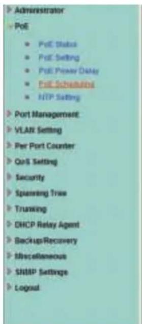
This page is for setting PoE Scheduling, it starts POE function at a specified time.
text_image
Administrator PoE • PoE Status • PoE Setting • PoE Privacy Date • PoE Scheduling • HTTP Setting Port Management VLAN Setting Per Port Counter QoS Setting Security Spanning Tree Training DHCP Relay Agent Backup/Recovery Miscellaneous SITMP Settings LogicalPoE Scheduling
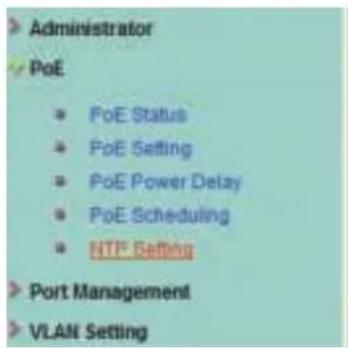
This page is for NTP setting.
text_image
> Administrator PoE PoE Status PoE Setting PoE Power Delay PoE Scheduling NTP Setting Port Management VLAN SettingNTP Setting
| System Time | 0:20:8 |
| NTP Server | #1 210.0.235.14 |
| #2 59.124.196.85 | |
| Time Zone | UTC 0:00 |
| Update | |
NTP Server: This is the IP address of the NTP information will be taken from.
Time Zone: Select your local time zone from this pull down list.
4.3 Port Management
4.3.1 Port configuration
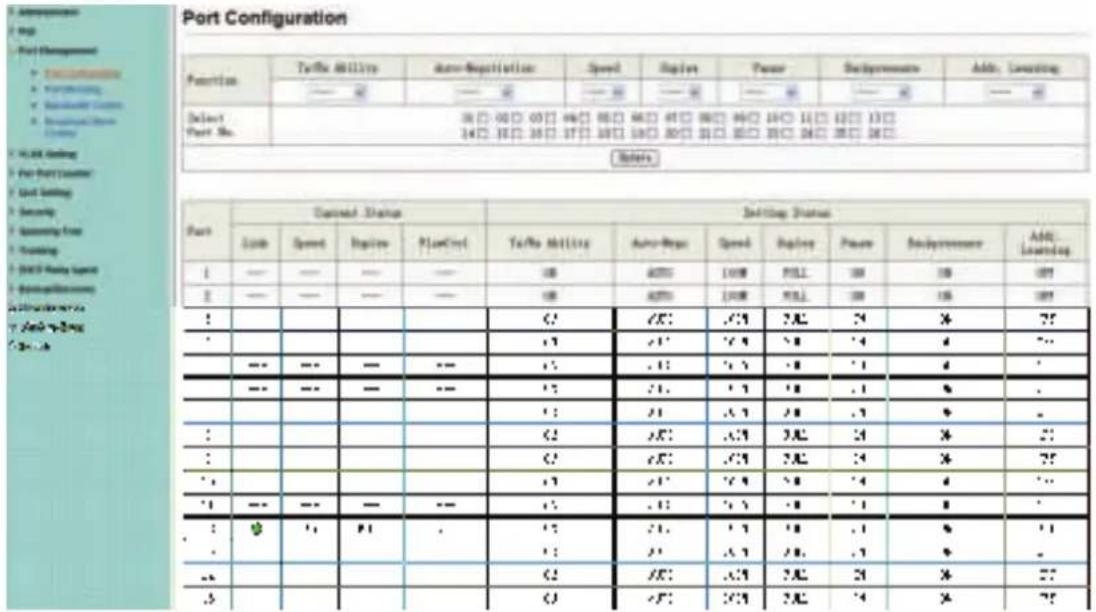
This page allows the user to configure operating mode of the physical port.
text_image
Port Configuration Function Turbo Utility Auto-Regulation Speed Ripley Power Background Add: Learning — — — — — — — — — — — — Select Port No. 30□ 00□ 05□ 06□ 08□ 09□ 10□ 11□ 12□ 13□ 14□ 15□ 16□ 17□ 18□ 19□ 20□ 21□ 22□ 23□ 24□ 25□ 26□ Bates Port Current Status Setting Status Node Speed Engine PlanFirst Turbo Utility Auto-Roger Speed Ripley Power Background AML Learning 1 — — — — — 100 ADTSI LOM PSLI 100 100 100 2 — — — — — 100 ADTSI LOM PSLI 100 100 100 1 : /C : /C : /A : /A : /A : /A : /A : /A : /A : /A : /A : /A : /A : /A : /A : /A : /A : /A : /A : /A : /A : /A : /A : /A : /A : /A : /A : /A : /A : /A : /A : /A : /A : /A : /A : /A : --- --- --- --- --- --- --- --- --- --- --- --- --- --- --- --- --- --- --- --- --- --- --- --- --- --- --- --- --- --- --- --- --- --- --- --- --- --- --- --- --- --- --- --- --- --- --- --- --- --- --- --- --- --- --- --- --- --- --- --- --- --- --- --- --- --- --- --- --- --- --- --- --- --- --- --- --- --- --- --- --- --- --- --- --- --- --- --- --- --- --- -1 - - - - - - - - - - - - - - - - - - - - - - - - - - - - - - - - - - - - - - - - - - - - - - - - - - - - - - - - - - - - - - - - - - - - - - - - - - - - - - - - - - - - - --- -- -- -- -- -- -- -- -- -- -- -- -- -- -- -- -- -- -- -- -- -- -- -- -- -- -- -- -- -- -- -- -- -- -- -- -- -- -- -- -- -- -- -- -- -- -- -- -- -- -- -- -- -- -- -- -- -- -- -- -- -- -- -- -- -- -- -- -- -- -- -- -- -- -- -- -- -- -- -- -- -- -- -- -- -- -- -- -- -- -- -- -- -- -- -- -- -- -- -- --Tx/Rx Ability: Allow choosing all or one port of Switch for further management, the available options is ALL & 01 to 16/24.
Auto-Negotiation: Enable and Disable. Being set as Auto, the speed and duplex mode are negotiated automatically. When you set it as Disable, you have to set the speed and duplex mode manually.
Speed: It is available for selecting hen the Negotiation column is set as Force. When the Negotiation column is set as Auto, this column is read-only.
Duplex: It is available for selecting when the Negotiation column is set as Force. When the Negotiation column is set as Auto, this column is read-only.
Pause: Flow Control for Full Duplex. When Flow Control is enabled, the switch can synchronize the speed with its peer to avoid the packet loss caused by congestion.
Backpressure: Flow Control for Half Duplex. A condition wherein a switch causes a transmitting device to hold off on sending data packets until the switch bottleneck has been eliminated.
Addr.Learning: Address learning is a service that characterizes a learning bridge, in which the source MAC address of each received packet is stored so that future packets destined for that address can be forwarded only to the bridge interface on which that address is located.
After completing the settings, press "Update" button to take effect. The setting will be reflected at current status window.
4.3.2 Port mirroring
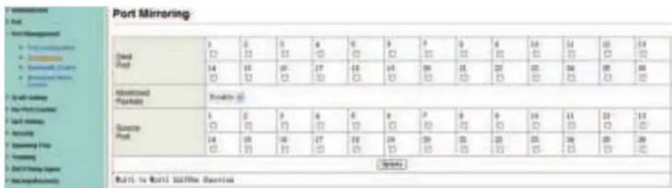
The port mirroring function is accomplished by setting the following items.
(a) Destination port: Theoretically it's possible to set more than one destination port in a network. Actually the port mirroring function will lower the network throughput, and therefore it's recommended to set "only one" destination port in a network.
(b) Monitored packets: (1) Disable: means this function is disabled. (2) RX: means copy the incoming packets of the selected source port to the selected destination port. (3) TX: means copy the outgoing packets of the selected source port to the selected destination port. (4) Tx & Rx: means the combination of Tx and Rx.
(c) Source port: The traffic source that will be copied to the destination port.
text_image
Port Mirroring 1 2 3 4 5 6 7 8 9 10 11 12 13 14 15 16 17 18 19 20 21 22 23 24 25 26 27 28 29 30 31 32 33 34 35 36 37 38 39 40 41 42 43 44 45 46 47 48 49 50 51 52 53 54 55 56 57 58 59 60 61 62 63 64 65 66 67 68 69 70 71 72 73 74 75 76 77 78 79 80 81 82 83 84 85 86 87 88 89 90 91 92 93 94 95 96 97 98 99 100(24-port version view)
4.3.3 Bandwidth Control
This page allows the setting of the bandwidth for each port. The TX rate and Rx rate can be filled with the number ranging 1 to 255. This number will be multiplied by the selected bandwidth resolution and the result is the real bandwidth.
| Port No. | Type | T1 Base | T2 Base | T3 Base | T4 Base | T5 Base |
| 1 | 1 - 2000 | 1 - 12 km | 4 | 1 - 2000 | 1 - 12 km | 1 - 2000 |
| 2 | 1 - 2000 | 1 - 12 km | 6 | 1 - 2000 | 1 - 12 km | 1 - 2000 |
| 3 | 1 - 2000 | 1 - 12 km | 6 | 1 - 2000 | 1 - 12 km | 1 - 2000 |
| 4 | 1 - 2000 | 1 - 12 km | 7 | 1 - 2000 | 1 - 12 km | 1 - 2000 |
| 5 | 1 - 2000 | 1 - 12 km | 8 | 1 - 2000 | 1 - 12 km | 1 - 2000 |
| 6 | 1 - 2000 | 1 - 12 km | 8 | 1 - 2000 | 1 - 12 km | 1 - 2000 |
| 7 | 1 - 2000 | 1 - 12 km | 8 | 1 - 2000 | 1 - 12 km | 1 - 2000 |
| 8 | 1 - 2000 | 1 - 12 km | 8 | 1 - 2000 | 1 - 12 km | 1 - 2000 |
4.3.4 Broadcast Storm Control
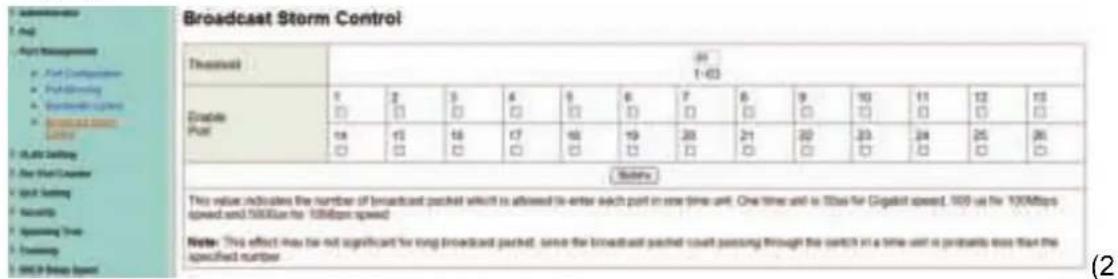
The broadcast storm control is used to block the excessive broadcast packets, the number ranging from 1 to 63.
text_image
Broadcast Storm Control Threatout 1-63 Enable Post 17 2 3 4 5 6 7 8 9 10 11 12 13 □ □ □ □ □ □ □ □ □ □ □ □ □ □ □ □ □ □ □ □ □ □ □ □ □ □ □ □ □ □ □ □ □ □ □ □ □ □ □ □ □ □ □ □ □ □ □ □ □ □ ○ Status: This value indicates the number of broadcast packets which is allowed to enter each port in one time unit. One time unit is 100% for Digasist speed, 100% as far 100Mbps speed and 10000ms for 100Mbps speed. Note: This effect may not significant for long broadcast packets, serve the broadcast packet count passing through the switch in a time unit is probably less than the specified number. (2)4-port version view)
For example: The broadcast storm of the port1\~8 are enabled and threshold is set to 10. The broadcast packets will be dropped when broadcast packets are more than threshold setting (packet length is 64 bytes).
Б ordered
text_image
Treated Gross Profit ? # # # # # # # # # # # # # # # # # # # # # # # # # # # # # # # # # # # # # # # # # # # # # # # # # # # # # # # # # # # # # # # # # # # # # # # # # # # # # # # # # # # # # # # # # # # # # # # # # # # #Value
Value # Value/Value/Value/Value/Value/Value/Value/Value/Value/Value/Value/Value/Value/Value/Value/Value/Value/Value/Value/Value/Value/Value/Value/Value/Value/Value/Value/Value/Value/Value/Value/Value/Value/Value/Value/Value/Value/Value/Value/Value/Value/Value/Value/Value/Value/Value/Value/Value/Value/Value/Value/Number
Value # Value/# Value/# Value/# Value/# Value/# Value/# Value/# Value/# Value/# Value/# Value/# Value/# Value/# Value/# Value/# Value/# Value/# Value/# Value/# Value/# Value/# Value/# Value/# Value/# Value/# Value/# Value/# Value/# Value/# Value/# Value/# Value/# Value/# Value/# Value/# Value/# Value/# Value/# Value/# Value/# Value/# Value/# Value/# Value/# Value/# Value/# Value/# Value/# Value/# Value/# Value (#)
4-port version view)
4.4 VLAN Setting
4.4.1 VLAN mode
The Switch supports two VLAN modes, tag based and port based. When the port based VLAN is selected, the tag setting will be useless. When the tag based VLAN is selected, the user can define the handling method of a VLAN tag to the specified port, including "add a
VLAN tag", "remove a VLAN tag" or "don't care" about VLAN tag.

text_image
VLAN Mode VLAN Mode Port Status VLAN Change VLAN exitWhen click the "Change VLAN mode" button, the mode will change to Tag Base VLAN.

text_image
1. Maintenance (ON) 2. Play 3. Post Management 4. ULMS Setting 5. Tool/Toolset 6. Use Deviation 7. Study to 1 Meeting 8. Play Work Condition 9. Cut Design 10. Security 11. Staffing Time 12. Training 13. EMCP Task Agent 14. Design/Recovery 15. Procurement 16. GMP Settings 17. Legend| VLAN Mode | Tag Board VLAN Change VLAN note | |||||||
| Tag Mode | Part 06 ○AddTag ○don't care ○RemoveTag | Part 02 ○AddTag ○don't care ○RemoveTag | Part 03 ○AddTag ○don't care ○RemoveTag | Part 04 ○AddTag ○don't care ○RemoveTag | Part 05 ○AddTag ○don't care ○RemoveTag | Part 06 ○AddTag ○don't care ○RemoveTag | Part 07 ○AddTag ○don't care ○RemoveTag | Part 08 ○AddTag ○don't care ○RemoveTag |
| Part 09 ○AddTag ○don't care ○RemoveTag | Part 10 ○AddTag ○don't care ○RemoveTag | Part 11 ○AddTag ○don't care ○RemoveTag | Part 12 ○AddTag ○don't care ○RemoveTag | Part 13 ○AddTag ○don't care ○RemoveTag | Part 14 ○AddTag ○don't care ○RemoveTag | Part 15 ○AddTag ○don't care ○RemoveTag | Part 16 ○AddTag ○don't care ○RemoveTag | |
| Part 17 ○AddTag ○don't care ○RemoveTag | Part 18 ○AddTag ○don't care ○RemoveTag | Part 19 ○AddTag ○don't care ○RemoveTag | Part 20 ○AddTag ○don't care ○RemoveTag | Part 21 ○AddTag ○don't care ○RemoveTag | Part 22 ○AddTag ○don't care ○RemoveTag | Part 23 ○AddTag ○don't care ○RemoveTag | Part 24 ○AddTag ○don't care ○RemoveTag | |
| Part 25 ○AddTag ○don't care ○RemoveTag | ||||||||
The egress packets of the output port will be added tag if add tag option is selected. The egress packets of the output will be stripped tag if remove tag option is selected. Don't care means the egress packets of the output port only forward to destination without adding or removing tag.
4.4.2 VLAN Member Setting
This page is used to set the VLAN ID. The VLAN ID is valid only when the tag based VLAN is enabled. In port based VLAN mode, the VLAN ID is useless.
Port based VLAN
Port1\~3 is set to same VLAN group and port4\~8 is set to another VLAN group.

text_image
Post Management H&D Setting • On the market • On the market • Aircraft Trading • Post Customer • On the Market • Security • Operating Power • Trading • SMO Using Agent • Electrical Recovery • Windstream • GROW Holdings • Legend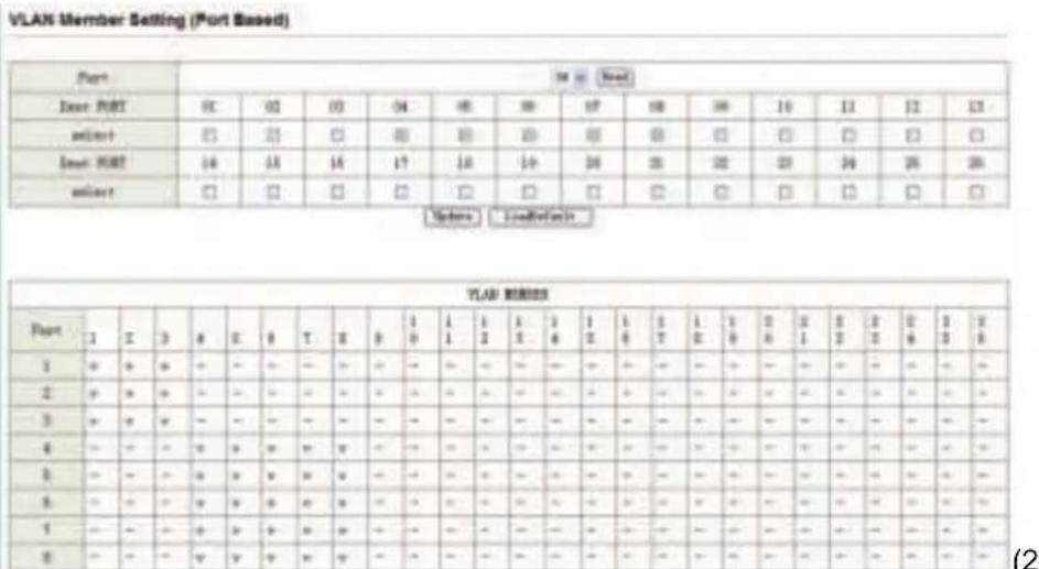
text_image
VLAN Member Setting (Port Based) Port Port 12 Port 12 Port 12 Port 12 Port 12 Port 12 Port 12 Port 12 Port 12 Port 12 Port 12 Port 12 Port 12 Port 12 Port 12 Port 12 Port 12 Port 12 Port 12 Port 12 Port 13 Port 13 Port 13 Port 13 Port 13 Port 13 Port 13 Port 13 Port 13 Port 13 Port 13 Port 13 Port 13 Port 13 Port 13 Port 13 Port 13 Port 13 Port 13 Port 13 Port 14 Port 14 Port 14 Port 14 Port 14 Port 14 Port 14 Port 14 Port 14 Port 14 Port 14 Port 14 Port 14 Port 14 Port 14 Port 14 Port 14 Port 14 Port 14 Port 14 Port 15 Port 15 Port 15 Port 15 Port 15 Port 15 Port 15 Port 15 Port 15 Port 15 Port 15 Port 15 Port 15 Port 15 Port 15 Port 15 Port 15 Port 15 Port 15 Port 15 Port 16 Port 16 Port 16 Port 16 Port 16 Port 16 Port 16 Port 16 Port 16 Port 16 Port 16 Port 16 Port 16 Port 16 Port 16 Port 16 Port 16 Port 16 Port 16 Port 16 Port 17 Port 17 Port 17 Port 17 Port 17 Port 17 Port 17 Port 17 Port 17 Port 17 Port 17 Port 17 Port 17 Port 17 Port 17 Port 17 Port 17 Port 17 Port 17 Port 17 Port 18 Port 18 Port 18 Port 18 Port 18 Port 18 Port 18 Port 18 Port 18 Port 18 Port 18 Port 18 Port 18 Port 18 Port 18 Port 18 Port 18 Port 18 Port 18 Port 18 Port 194-port version view)
Tag based VLAN
The following figure shows: 1, 2, 3, 4, 5, 6, 7 port in the same VLAN group. The 2 port tag VID number is 123.

text_image
VLAN Member Setting (Tag Based) VLD (1 * bese) SAD Add: Enter a VLD, select the VLD connector for this entry and then press this button to add a VLD entry to the table. Del: Select a VLD in the table and then press this button to remove a VLD entry from the table. Options Modify the selecting VLD retro-select VLD and then press the button. FLAB Breaker Port 00 00 00 00 00 00 00 00 00 00 00 00 00 FLAB Breaker Port 00 10 15 12 12 14 18 18 18 FLAB Breaker Port 07 18 19 09 21 22 23 24 FLAB Breaker Port 00 26 - - - - - - - - - - pnlnt Prlnt Prlnt Prlnt Prlnt Prlnt Prlnt Prlnt Prlnt Prlnt Prlnt Prlnt Prlnt Prlnt Prlnt Prlnt Prlnt Prlnt Prlnt Prlnt Prlnt Prlnt Prlnt Prlnt Prlnt Prlnt Prrnnt Prrnnt Prrnnt Prrnnt Prrnnt Prrnnt Prrnnt Prrnnt Prrnnt Prrnnt Prrnnt Prrnnt Prrnnt Prrnnt Prrnnt Prrnnt Prrnnt Prrnnt Prrnnt Prrnnt Prrmnt Prrmnt Prrmnt Prrmnt Prrmnt Prrmnt Prrmnt Prrmnt Prrmnt Prrmnt Prrmnt Prrmnt Prrmnt Prrmnt Prrmnt Prrmnt Prrmnt Prrmnt Prrmnt Prrmnt Prrnnt Prrnnt Prrnnt Prrnnt Prrnnt Prrnnt Prrnnt Prrnnt Prrnnt Prrnnt Prrnnt Prrnnt Prrnnt Prrnnt Prrnnt Prrnnt Prrnnt Prrnnt4-port version view)
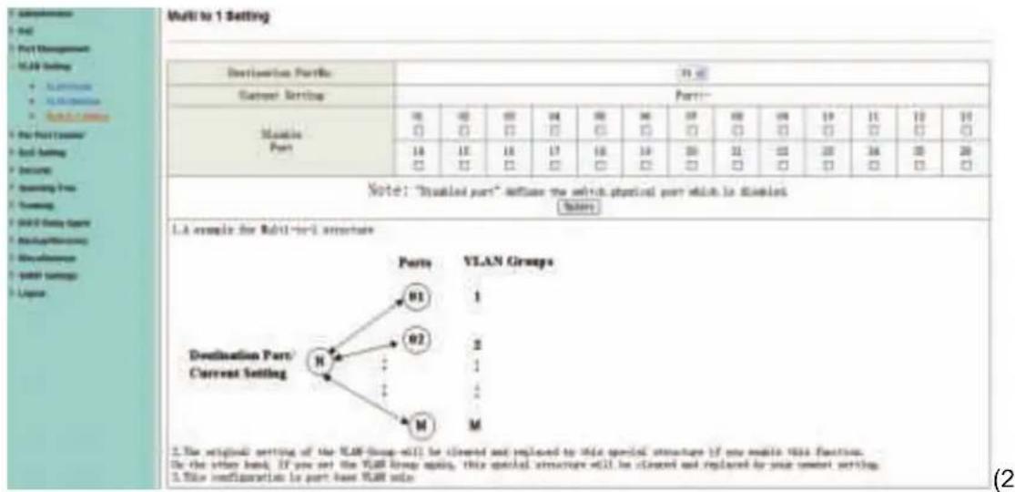
4.4.3 Multi-to-1 Setting
This setting is exclusive to VLAN setting on "VLAN member setting". When VLAN member setting is updated, multi-to-1 setting will be void and vice versa. The "Disable Port" means the port is excluded in this setting.
text_image
Multi to 1 Setting Destination Port#: 75.00 Current Setting: Part:** Structure Port: 00 02 03 04 05 06 07 08 09 10 11 12 13 □ □ □ □ □ □ □ □ □ □ □ □ □ □ 10 11 12 13 14 15 16 17 18 19 20 21 22 23 24 25 26 □ □ □ □ □ □ □ □ □ □ □ □ □ □ □ □ Note: "Stabilized port" influences the switch physical port which is disabled. Notes: 1.A sample for Multi-to-1 structure Destination Port/ Current Setting Parts VLAN Groups 01 1 02 2 ↓ ↓ M M 2. The original setting of the VLAN Group will be cleaned and replaced to this special structure if any model VLSA Function. Is the other hand. If you set the VLAN group again, this special structure will be cleaned and replaced by your custom setting. This configuration is part base VLAN side.4-port version view)
Note: If the VLAN mode changes from port base to tag base, the setting of the port base will be cleared. Similarly, if the VLAN mode changes from tag base to port base, the setting of the tag base will be cleared.

text_image
7.5.1.136 Design Features Based Testing will use basic data loading. Please click your user to access your Web page for your website. You can you use your Web page for your www.webpage.com.In tag base mode, adding or removing tag doesn't affect the source port connected with the web.
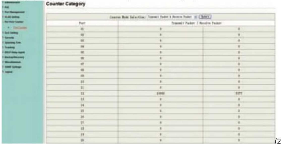
4.5 Per Port Counter
This page provides port counter for each port. There are 4 groups of statistics in total.
text_image
Counter Category Counter Mode Selection: Tramere Packet & Resource Packet Tramere Packet Port Tramere Packet / Resource Packet 0 0 0 0 0 0 0 0 0 0 0 0 0 0 0 0 19999 0071 0 0 0 0 0 0 0 0 0 0 0 0 0 0 0 0 0 0 0 0 0 0 0 0 0 0 0 0 0 0 0 0 0 0 0 0 0 0 0 0 0 0 0 0 0 0 0 0 0 0 24-port version view)
4.6 QoS Setting
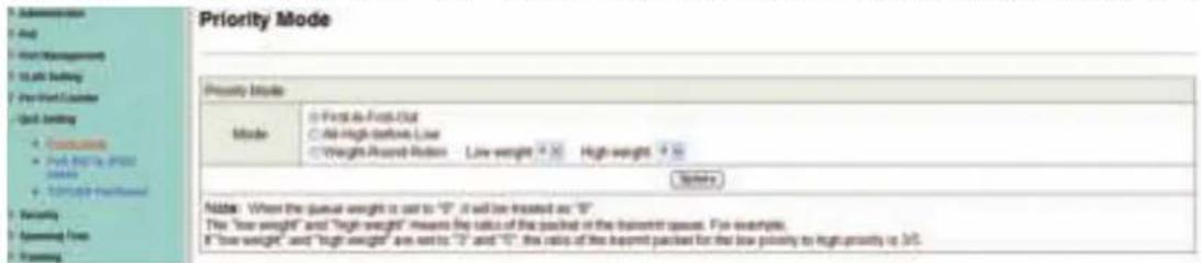
4.6.1 Priority mode
This page allows the user to set the scheduling mode for the TX packets priority. When the queue weight is set to "0", it will be treated as "8". The "low weight" and "high weight" means the ratio of the packet in the transmit queue. For example, If "low weight" and "high weight" are set to "3" and "5", the ratio of the transmit packet for the low priority to high priority is 3/5.
text_image
Priority Mode Priority Mode Mode: ● First to First-Off ○ All high above Low ○ Weight Award-Rotation Low weight 100 High weight 90 Notes Notes: When the gaveal weight is set to "0" it will be treated as "0" The "low weight" and "high weight" means the ratio of the packed or the train/roll gaveal. For example, 8 "low weight" and "high weight" are set to "0" and "0", the ratio of the packet packed for the low priority to high priority is 3/5.4.6.2 Port, 802.1p, IP/DS based
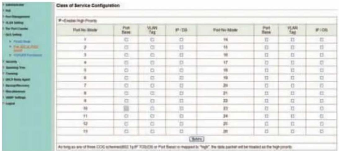
There are three COS types for this setting. The user can select more than one item for each port.
text_image
Class of Service Configuration IP - Eddas High Priority Port No. Mode Port State VLAN Tag IP / ID Port No. Mode Port State VLAN Tag IP / ID 1 ☐ ☐ ☐ 14 ☐ ☐ ☐ 2 ☐ ☐ ☐ 15 ☐ ☐ ☐ 3 ☐ ☐ ☐ 16 ☐ ☐ ☐ 4 ☐ ☐ ☐ 17 ☐ ☐ ☐ 5 ☐ ☐ ☐ 18 ☐ ☐ ☐ 6 ☐ ☐ ☐ 19 ☐ ☐ ☐ 7 ☐ ☐ ☐ 20 ☐ ☐ ☐ 8 ☐ ☐ ☐ 21 ☐ ☐ ☐ 9 ☐ ☐ ☐ 22 ☐ ☐ ☐ 10 ☑ ☐ ☐ 23 ☐ ☐ ☐ 11 ☐ ☐ ☐ 24 ☐ ☐ ☐ 12 ☐ ☐ ☐ 25 ☐ ☐ ☐ 13 ☐ ☐ ☐ 26 ☐ ☐ ☐ (Before) As being as one of three COG echenness/002.1p/F /100/05 or Post State is mapped to "High". For data partner will be treated as the high priority.As long as any of three CoS schemes(802.1p, IP TOS/DS or Port Base) is mapped to "high", the data packet will be treated as the high priority.
4.6.3 TCP/UDP Port Based
This page allows the network administrator to assign the specific application to a priority queue. When the TCP/UDP port QoS function "override" item is selected, the Port_based, Tag_based, IP TOS_based, CoS listed above will be ignored.
| Class of Service Configurations | |
| Protocol | Option |
| FTP(20,21) | F-1-F+ 20 |
| SHP(22) | F-1-F+ 20 |
| TELNET(23) | F-1-F+ 20 |
| SMTP(25) | F-1-F+ 20 |
| DNS(55) | F-1-F+ 20 |
| TFTP(66) | F-1-F+ 20 |
| HTTP(SD.8999) | F-1-F+ 20 |
| POP(119) | F-1-F+ 20 |
| GETS(119) | F-1-F+ 20 |
| SMTP(120) | F-1-F+ 20 |
| NADICOS(137–139) | F-1-F+ 20 |
| MAP(143,233) | F-1-F+ 20 |
| SNAP(161,162) | F-1-F+ 20 |
| HTTP(S483) | F-1-F+ 20 |
| MEN(1963) | F-1-F+ 20 |
| MED_SDP(3388) | F-1-F+ 20 |
| DQARID(5900) | F-1-F+ 20 |
4.7 Security
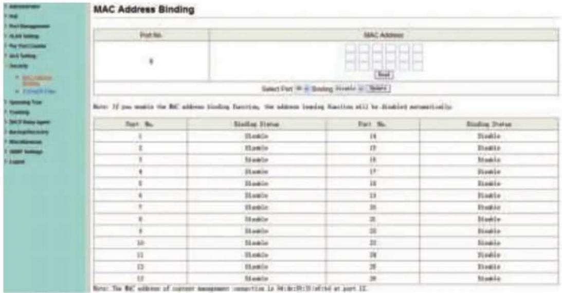
4.7.1 MAC Address Binding
This is a port binding feature. This function provides a method for the administrator to specify the relationship between the physical port and the MAC address. By specifying the MAC address to each port, the switch can only forward the packets with source specified in
the table. Each port can correspond to up to 3 MAC addresses.
text_image
MAC Address Binding Port No. MAC Address 0 [ ] [ ] Select Port [ ] Binding Status [ ] Status Note: If you enable the MAC address binding function, the address loading status will be disabled automatically. Port No. Sliding Status Part No. Sliding Status 1 Stable 14 Stable 2 Stable 17 Stable 3 Stable 18 Stable 4 Stable 17 Stable 5 Stable 18 Stable 6 Stable 19 Stable 7 Stable 20 Stable 8 Stable 21 Stable 9 Stable 22 Stable 10 Stable 23 Stable 11 Stable 24 Stable 12 Stable 25 Stable 13 Stable 26 Stable Note: The MAC address of current assignment connection is WIdder0101aft14 at port IS.4.7.2 TCP/UDP Filter
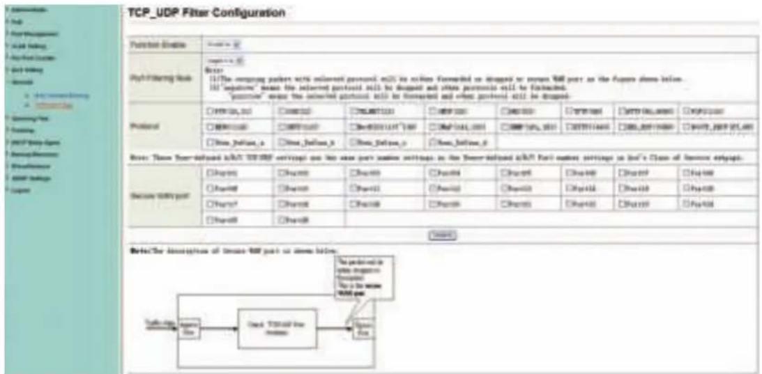
By selecting the TCP/UDP port, the user can optionally block some specific applications. There are two kinds of protocol lists. The positive list makes the switch to forward the selected protocol and drop other protocols. The negative list makes the switch drop the selected protocol and forward other protocol. The protocol is checked at the selected secure WAN port.
text_image
TCP_UDP Filter Configuration Function Address http://www.163.com/ http://www.163.com/ http://www.163.com/ http://www.163.com/ http://www.163.com/ http://www.163.com/ http://www.163.com/ http://www.163.com/ http://www.163.com/ http://www.163.com/ http://www.163.com/ http://www.163.com/ https://www.163.com/ http://www.163.com/ http://www.163.com/ http://www.163.com/ http://www.163.com/ http://www.163.com/ http://www.163.com/ http://www.163.com/ http://www.163.com/ http://www.163.com/ http://www.163.com/ http//www.163.com/ http://www.163.com/ http://www.163.com/ http://www.163.com/ http://www.163.com/ http://www.163.com/ http://www.163.com/ http://www.163.com/ http://www.163.com/ http://www.163.com/ http://www.163.com/ http://w2w2w2w2w2w2w2w2w2w2w2w2w2w2w2w2w2w2w2w2w2w2w2w2w2w2w2w2w2w2w2w2w2w2w2w2w2w2w2w2w2w2w2w2w2w2w2w2w2w2w http://www.163.com/ http://www.163.com/ http://www.163.com/ http://www.163.com/ http://www.163.com/ http://www.163.com/ http://www.163.com/ http://www.163.com/ http://www.163.com/ http://www.163.com/ http://www.163.com/The Switch supports two methods to filter TCP/UDP protocol. Allow means that when the port number of the selected port matches the port number of the filter setting, the packets will be forwarded to destination port. Deny means that when the port number of the selected port doesn't match port number of the filter setting, the packets will be forwarded to destination port.
4.8 Spanning Tree
4.8.1 STP Bridge Settings
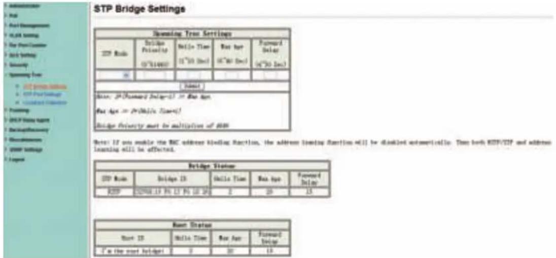
STP (Spanning Tree Protocol) is the acronym for spanning tree protocol, the protocol can be applied to loop network, the algorithm by a certain path redundancy, while loop network loop-free tree pruning into the network in order to avoid reporting Man in the loop network hyperplasia and infinite loop. STP protocol will continue to 50s, this is the PC is turned on and some 50s before they can access, for data transfer. RSTP STP improved algorithm, within the agreement time to 1s.
text_image
STP Bridge Settings Streaming Tree Settings STP Route Bridge Priority Delta Time Ret Area Forward Delay 03°51'48'07 11"50 Dec 06"80 Dec 04"30 Dec [ ] Status Base: 24 (Standard Delay=2) > Base Type. Base Type = Pro(Only Type) Bridge Priority must be multipliers of 8000 Note: If not enable the RBC address blocking function, the address limiting function will be disabled automatically. Then both RDP/SP and address learning will be affected. Bridge Status STP Route Bridge ID Delta Time Ret Area Forward Delay RDP 029M-19 NC LT NC LT 20 2 20 15 Base Status Base ID Delta Time Ret Area Forward Delay I'm the next bridge 2 20 154.8.2 STP Port Settings
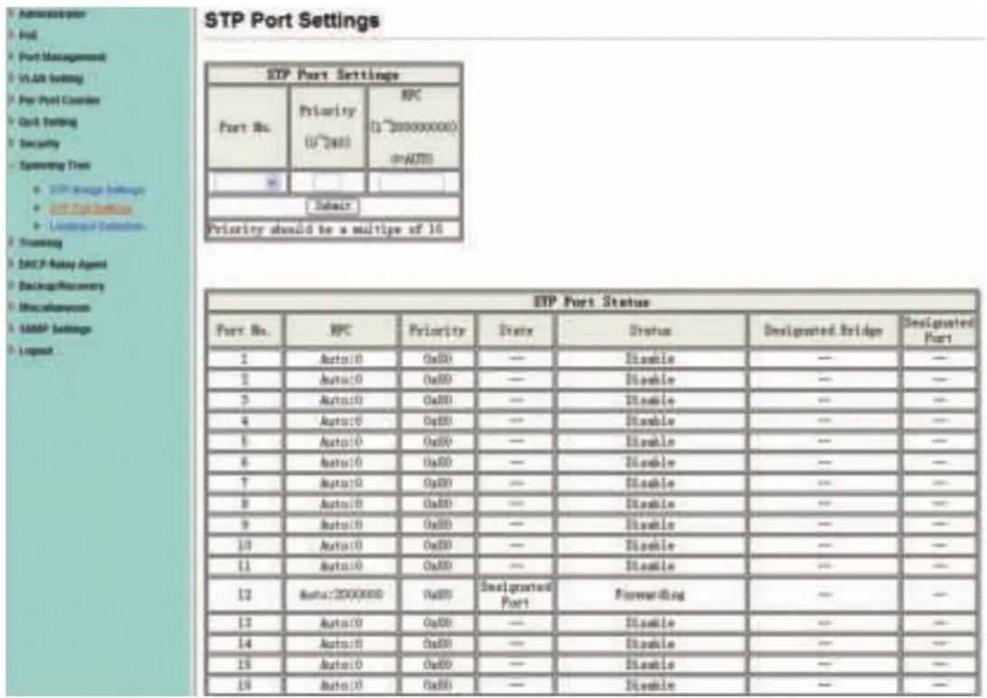
This feature is available to you to switch the priority of each port and RPC set, usually set according to the following priority rules, and RPC can remain the default.
RPC: Root Path Cost. The value range is 0 \~ 200000000, used to determine the port to the root path cost, often with the speed, so when set to Auto, its value is inversely proportional to speed.
Election root port, in accordance with the following principles. COST - Port ID, compare the COST value, that is, the cost of the port to the root bridge. COST lower the value the more the priority.
【COST VALUE】
| Bandwidth | COST |
| 10Gps | 2 |
| 1Gps | 4 |
| 100M | 19 |
| 10M | 100 |
text_image
STP Port Settings STP Port Settings Port No. Priority IPC (0~240) (1~200000000) (0~240) (0~240) Subair Priority should be a multiple of 16 STP Port Status Port No. IPC Priority Event Status Designated Bridge Designated Port 1 Auto10 0x80 — Disable — — 2 Auto10 0x80 — Disable — — 3 Auto10 0x80 — Disable — — 4 Auto10 0x80 — Disable — — 5 Auto10 0x80 — Disable — — 6 Auto10 0x80 — Disable — — 7 Auto10 0x80 — Disable — — 8 Auto10 0x80 — Disable — — 9 Auto10 0x80 — Disable — — 10 Auto10 0x80 — Disable — — 11 Auto10 0x80 — Disable — — 12 Auto:2000000 0x80 Designated Port Favoring 13 Auto10 0x80 — Disable — — 14 Auto10 0x80 — Disable — — 15 Auto10 0x80 — Disable — — 16 Auto10 0x80 — Disable — —4.8.3 Loopback Detection
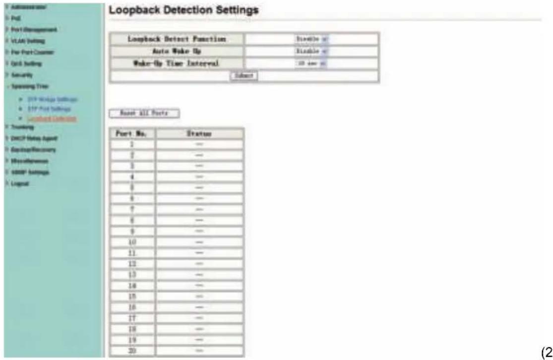
The features available to you under the loop test set, the "Loopback Detect Function", set to "Enable". When you produce the lower loop switch when the switch will automatically block out the port connecting to ensure other ports work.
When you set the "Auto Wake Up" and "Wake-Up Time Interval" option, and the network loop appears when the intervals, the switch port will wake up trying to loop until the fault discharged.
Reset All Ports: This button provides a key to force you to reset the port function.
Status: Display the current status of all ports.
text_image
Loopback Detection Settings Loopback Detect Function Auto Wake Up Wake-Up Time Interval Subtest Reset ALL Ports Port No. Status 1 — 2 — 3 — 4 — 5 — 6 — 7 — 8 — 9 — 10 — 11 — 12 — 13 — 14 — 15 — 16 — 17 — 18 — 19 — 20 —4-port version view)
4.9 Trunking
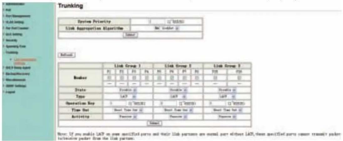
Port aggregation is to bring together multiple ports together to form a group to achieve entry / exit load in the aggregation group, all members of the port-sharing, while also providing a higher connection reliability.
Note: According to LACP specifications, the same group for each Member port Trunk connection speed and Duplex must be consistent, otherwise not work properly.
text_image
Trunking System Priority Link Aggregation AlGORITHM Link Group 1 Link Group 2 Link Group 3 Member State Type Operation Type Time Set Activity Subnet Note: If you enable LSCP on own notified parts and their link partners are normal part either LSCP, these specified parts cannot transmit packet transmission packet from the link parties.System Priority: Set the Switch System Priority, a value of 1 to 65535.
Link Aggregation Algorithm: MAC Src on behalf of Source MAC address. MAC Dst on behalf of Destination MAC address.
4.10 DHCP Relay Agent
4.10.1 DHCP Relay Agent
DHCP provides a transparent transmission to DHCP broadcast packet. It can transmitted broadcast packet in one DHCP client(or server) to another segments of the DHCP server(or client) transparently. Client in subnet can communicate with other subnet DHCP server through DHCP Relay.
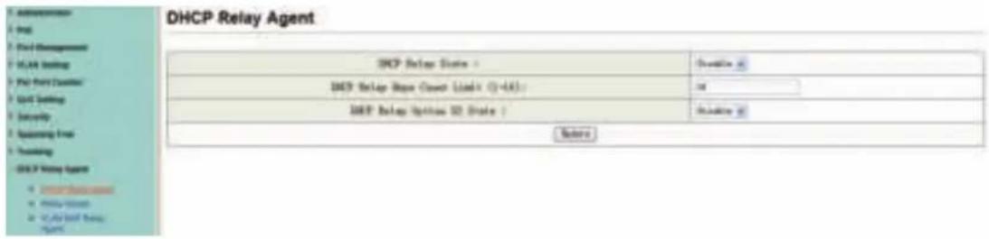
text_image
DHCP Relay Agent DHCP Relay State 100% ① DHCP Relay State (C-4A) 14 DHCP Relay Option SD State 100% ② Before4.10.2 Relay Server
Set the DHCP server IP.
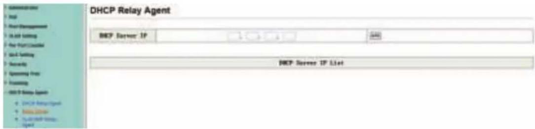
text_image
DHCP Relay Agent DHCP Server IP DHCP Server IP List4.10.3 VLAN MAP Relay Agent
Enter the VLAN ID value within 1-4094.
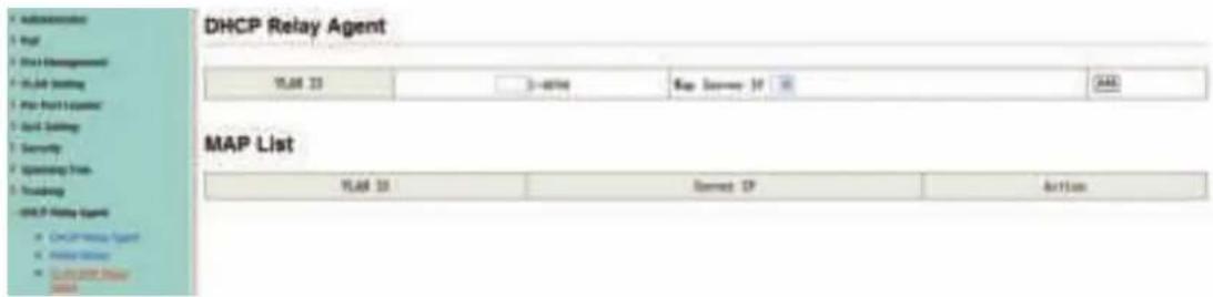
text_image
DHCP Relay Agent IP Address 23 3-40766 Map Address: 19 MAP MAP List IP Address 23 Connection: 19 Action OK/OK Relay Agent OK/OK Relay Agent OK/OK Relay Agent OK/OK Relay Agent4.11 Backup/Recovery
This function provides the user with a method to backup/recovery the switch configuration. The user can save configuration file to specified path. If the user wants to recover the original configuration, which is saved at the specified path, entering the password and then pressing the "Update" button could recover the original configuration.
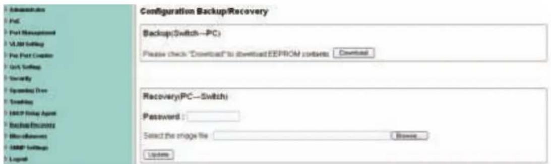
text_image
Administration Post Post Management VLAN Setting Pre Post Customer GRT Setting Security Screening Drive Scrolling HKEY Policy Agent Backslash Documents Miscellaneous HAPP Settings Legend Configuration Backup/Recovery Backup(Switch—PC) Please check "Download" to download EEPROM contexts Download Recovery(PC—Switch) Password : Select the image file Browse UpdateThe contents of the EEPROM can be saved to specific path, and the default name is down.bin.
Configurator B: 100%

text_image
Backup/which, PC Please ask "Don't know" to read INFO! to let us. Cancel
text_image
Page number: Page number: * * * : 10000000000000000000000000000000000000000000000000000000000000000000000000000000000000000 1.2.2.2.2.2.2.2.2.2.2.2.2.2.2.2.2.2.2.2.2.2.2.2.2.2.2.2.2.2.2.2.2.2.2.2.2.2.2.2.2.2.2.2.2.2.2.2.2.2.2.74.12 Miscellaneous
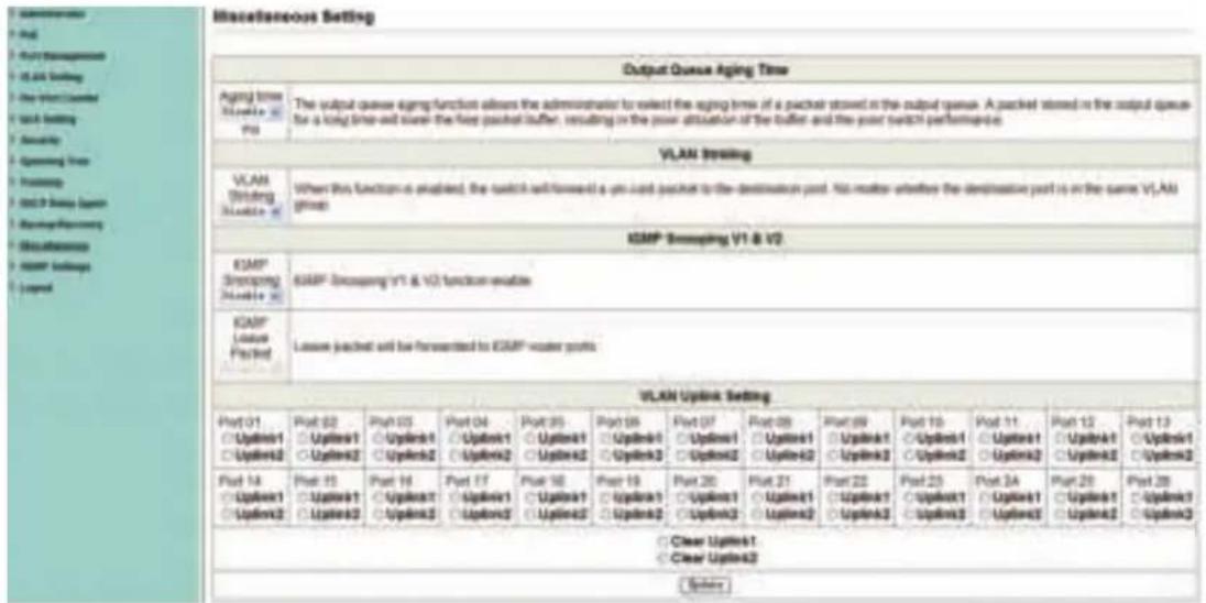
Miscellaneous is used to configure output queue aging time, VLAN stride, IGMP snooping, and VLAN uplink function setting.
text_image
Miscellaneous Setting Output Queue Aging Time Agency time Shuttle is Port The output queue aging function allows the administrator to select the aging break of a packet stored in the output queue. A packet stored in the output queue for a long time-well transfer the keep packet buffer, resulting in the power attenuation of the buffer and the point switch performance VLAN routing VLAN Routing Routing Time Routing USB9 Service Open Routing Reporting Securities USB9 Settings Loop E2MP Statusing V1 & V2 E2MP Routing V1 & V2 function enables E2MP Leave Packet Leave packed will be forwarded to E2MP water ports VLAN Uplink Setting Port 01 ○ Uplink1 ○ Uplink2 ○ Uplink3 Port 02 ○ Uplink1 ○ Uplink2 Port 03 ○ Uplink1 ○ Uplink2 Port 04 ○ Uplink1 ○ Uplink2 Port 05 ○ Uplink1 ○ Uplink3 Port 06 ○ Uplink1 ○ Uplink3 Port 07 ○ Uplink1 ○ Uplink3 Port 08 ○ Uplink1 ○ Uplink3 Port 09 ○ Uplink1 ○ Uplink3 Port 10 ○ Uplink1 ○ Uplink3 Port 11 ○ Uplink1 ○ Uplink3 Port 12 ○ Uplink1 ○ Uplink3 Port 13 ○ Uplink1 ○ Uplink3 Port 14 ○ Uplink1 ○ Uplink2 Port 15 ○ Uplink1 ○ Uplink3 Port 16 ○ Uplink1 ○ Uplink3 Port 17 ○ Uplink1 ○ Uplink3 Port 18 ○ Uplink1 ○ Uplink3 Port 19 ○ Uplink1 ○ Uplink3 Port 20 ○ Uplink1 ○ Uplink3 Port 21 ○ Uplink1 ○ Uplink3 Port 22 ○ Uplink1 ○ Uplink3 Port 23 ○ Uplink1 ○ Uplink3 Port 24 ○ Uplink1 ○ Uplink3 Port 25 ○ Uplink1 ○ Uplink3Output Queue Aging Time
This function is enabled for avoiding poor utilization of switch while pause packets is received. The normal packets from transmitted port (port1) can be forwarded to other port if port2 continues to assert pause frame.
VLAN Striding
By selecting this function, switch will forward unicast packets to destination port, no matter whether destination port is in the same VLAN.
IGMP Snooping V1 & V2
This function is enabled for supporting IGMPv1, IPMPv2 protocol to create IGMP group.
Uplink port
This function allows different VLAN use their individual uplink port to forward packets. In a normal application, "only one" uplink port can be selected in a switch.
4.13 SNMP Settings
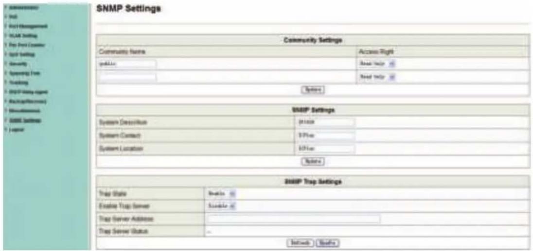
SNMP(Simple Network Management Protocol), used to manage the communication line. You can Enable or Disable SNMP Settings here.
text_image
SNMP Settings Community Settings Community Name Access Right public Read help Read help System SNMP Settings System Description $1000 System Contact $7500 System Location $5000 Noise SNMP Trap Settings Trap State Busks Enable Trap Server Susks Trap Server Address Trap Server Status Options Busks4.14 Logout
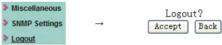
Press "Logout" button to logout web page.
flowchart
graph LR
    A["Miscellaneous"] --> B["SNMP Settings"]
    B --> C["Logout"]
    D["Logout?"] --> E["Accept"]
    D --> F["Back"]
Appendix: Technical Specifications
| Model | DN-95312 DN-95313 | ||
| Number of Ports | 16 x 10/100Mbps Auto-Negotiation ports | 24 x 10/100Mbps Auto-Negotiation ports,2 x 1000Mbps Combo | |
| LED Indicators | 10/100M | Link/Act | |
| POE | PoE | ||
| Power | Power | ||
| PoE Power | Power-: pin 4 & pin 5 Power+: pin 4 & pin 5 | ||
| Power+: pin 7 & pin 8 Power-: pin 7 & pin 8 | |||
| Transfer Method Store-and-Forward | |||
| Switching Capacity | 3.2G 8.8G | ||
| MAC Address Learning Automatically learning, automatically Update 4K | |||
| Standards IEEE802.3 10Base-T, IEEE802.3u 100Base-TX, IEEE802.3af, IEEE802.3at | |||
| Network Media (RJ-45) | 10BASE-T: UTP category 5 cable (maximum 100m) | ||
| 100BASE-T: UTP category 5,5e cable (maximum 100m) | |||
| 1000Base-T: UTP category 5e, 6 cable (maximum 100m) | |||
| Dimensions (L × W × H) 440*208*44 mm | |||
| Environment | Operating Temperature: 0°C~40°C | ||
| Operating Humidity: 10%~90% non-condensing | |||
| Storage Temperature: -10°C~70°C | |||
| Storage humidity: 5%~90% non-condensing | |||
| AC Input AC: 100V~240V 50/60HZ | |||
| Power consumption | 260 W | 330 W | |