
CR01 Flowcheck - Washing machine DYSON - Free user manual and instructions
Find the device manual for free CR01 Flowcheck DYSON in PDF.

| Brand | Dyson |
| Model | CR01 Flowcheck |
| Product Type | Washing Machine |
| Loading Type | Front-loading |
| Drum Technology | Contra-rotating dual drum system |
| Control Type | Electronic controls with display |
| Energy Supply | 230 V, 50 Hz, 10 A |
| Water Connection | Cold water fill with solenoids |
| Dimensions (H x W x D) | Approx. 850 x 600 x 600 mm |
| Weight | Approx. 80 kg |
| Flow Check System | Yes, includes micro switch and float |
| Soap Dispenser | Removable, with water solenoids |
| Heater Element | Removable, replaceable |
| Door Lock | Electrical door lock with cable connector |
| Drive System | Belt-driven, with gearbox and planet rings |
| Drum Bearings | Replaceable: 633007c (90x50x34) and SS-6904-2RS-MTK |
| Tub Seals | 70x100x8 mm nitrile rotary shaft oil seal |
| Maintenance Access | Removable top, front, and back panels |
| Waste Pump | Removable, connected via rubber hose |
| Safety Precautions | Disconnect water and electricity before repair |
Frequently Asked Questions - CR01 Flowcheck DYSON
User questions about CR01 Flowcheck DYSON
0 question about this device. Answer the ones you know or ask your own.
Ask a new question about this device
Download the instructions for your Washing machine in PDF format for free! Find your manual CR01 Flowcheck - DYSON and take your electronic device back in hand. On this page are published all the documents necessary for the use of your device. CR01 Flowcheck by DYSON.
USER MANUAL CR01 Flowcheck DYSON
natural_image
Exterior view of a silver washing machine with purple and gold buttons (no text or symbols visible)DYSON CR01
DRUM BEARING REPAIR
natural_image
Purple washing machine with visible door and handle (no text or symbols)I have written this guide assuming that the reader has no knowledge on how to dismantle any part of the Dyson CR01. Having never worked on a CR02, I am unaware if the construction of that model differs greatly.
I have borrowed various images from the net and thank everyone for their contribution.
Read each paragraph twice before starting that phase of dismantling.
Tools required.
a) Set of Torx bits / screwdrivers
b) Large hammer
c) Bolster.
d) Set of metric spanners / sockets
e) Digital Camera. (Always a good idea to photograph in situ before your remove)
1) Disconnect from the water and electricity supply and remove hoses. Drain as much water from the machine as possible by removing the coin trap cover and putting the drain pipe as low as possible.
2) Remove the top cover. Remove the two Phillips screws at the rear of the cover and slide it backwards.
3) Remove soap dispenser. The yellow catch at the rear of the dispenser allows it to be removed.
4) Remove front controls / display.
a) This is held on with two torx screws and when removed should be slid downwards. This will release the plastic tabs that hold it in place.
b) Disconnect the ribbon cable from where it attached to the machine body.
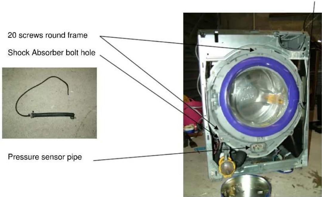
c) Remove the pressure sensor pipe. This just pulls off.
d) Disconnect the four power cables to the main on / off switch. The position of the cables should be recorded for reassembly.
The entire control panel assembly should now be free
5) Remove exterior door. This is held in place with spring clips / hinges that are visible. I found it easy to insert a flat screw driver into the hinge and push down the yellow clip.
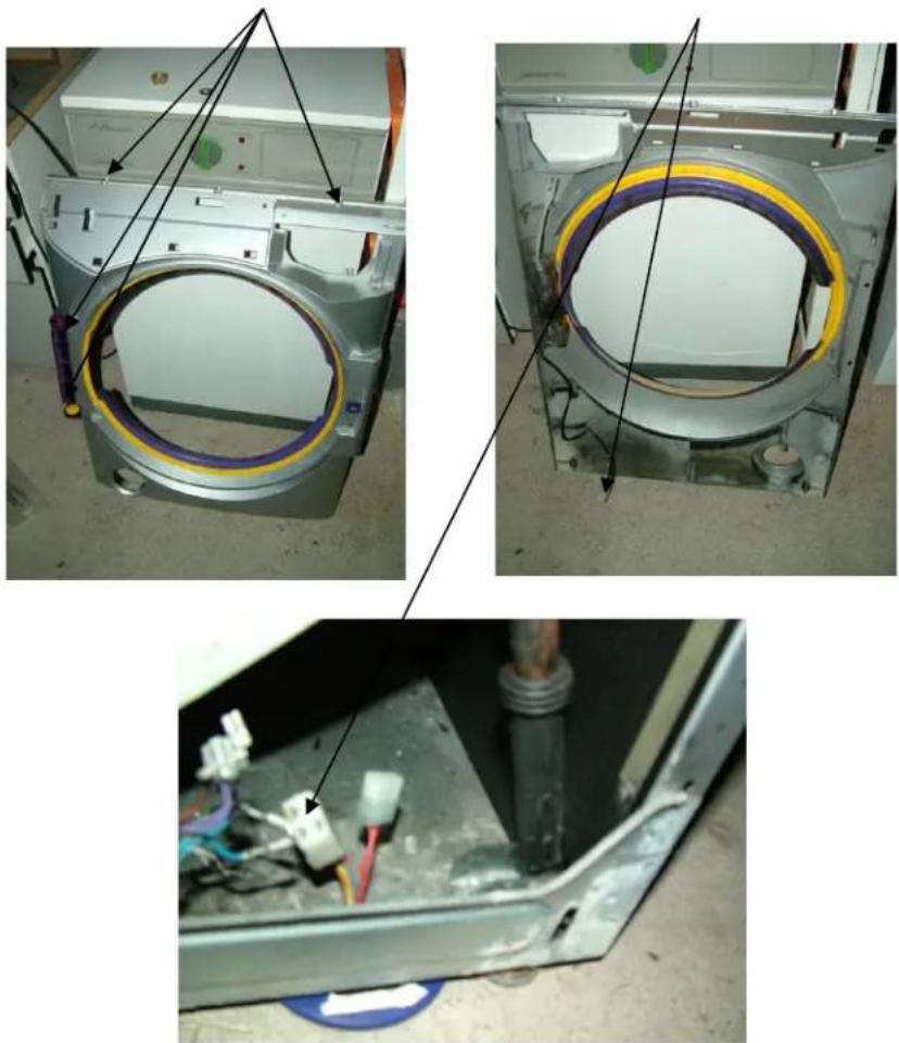
6) Remove front panel. This is held in place with 4 torx screws and a number of plastic tabs. Care should be taking not to break the plastic tabs. 2 screws are clearly visible on the top of the panel and the other two are recessed into the hinge of the exterior door. If you have not already removed the coin trap cover then this is the time do it as the front
panel will not come off while it is in place. After the screws and trap have been removed gently slide the panel UPWARDS and it will come away from the machine. It will however still be attached by a cable connecting the door lock which can be disconnected at the base of the machine.
Screws Door Lock Connector
natural_image
Three-panel photo showing a washing machine interior with visible wiring and components, no text or symbols present.7) Remove the back panel. 7 screws hold it in place. Ignore the red part as I borrowed this image from the Dyson unpacking instructions
8) Remove drive belt.
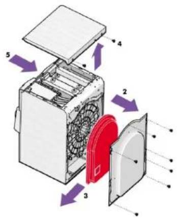
9) Remove Drive wheel. This is held in place with a single Torx screw.
Screw
natural_image
Interior view of a mechanical device showing internal components and a circular fan (no visible text or symbols)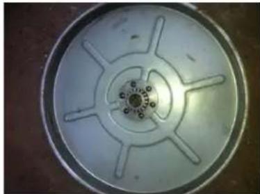
natural_image
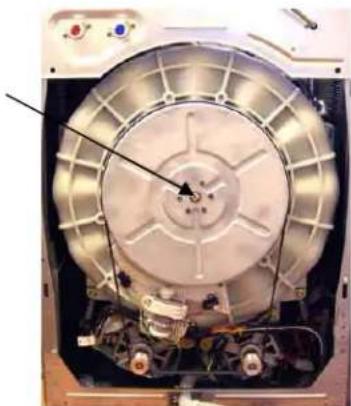
Circular mechanical component with radial slots and central hub (no text or symbols visible)10) Remove the gear box. This sits on the centre spline and is not held by any form of retaining screw or clip. Gently persuade it from the spline. You will see when you pull that it is spring loaded and care must be taken not to dislodge the spring retaining clips at the back.
natural_image
Close-up of a mechanical component with metallic blades and central hub (no visible text or symbols)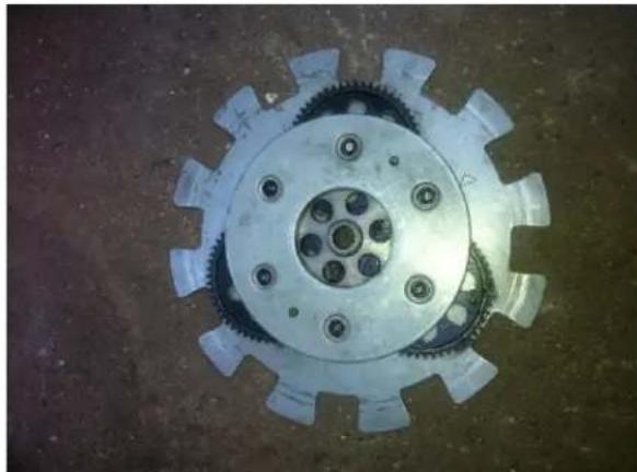
natural_image
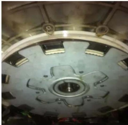
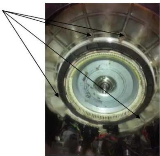
Close-up of a mechanical gear with multiple teeth and central hub (no text or symbols visible)11) Loosen the planet ring drive motor. This is held in by a single screw which will release the retaining clamp. It does not need to be fully removed as it can be allowed to hand loose until you remove the planet rings.
Planet Ring Drive Motor
natural_image
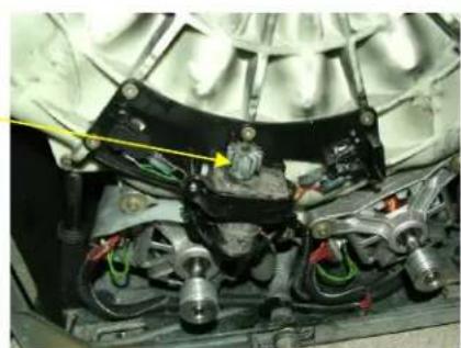
Close-up of mechanical components with visible wiring and a yellow arrow pointing to a component (no text or symbols)12) Remove the Planet Rings. They are held in by 4 clamps attached to the rear of the tub
Clamps
natural_image
Close-up of a mechanical component with concentric rings and internal gears, no visible text or symbols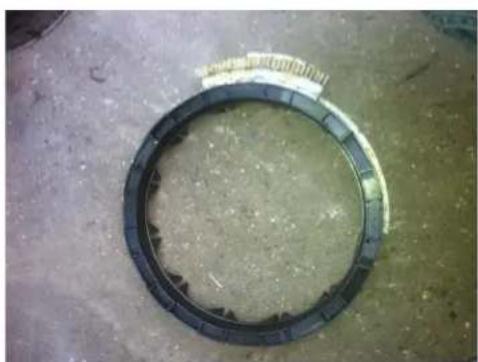
natural_image
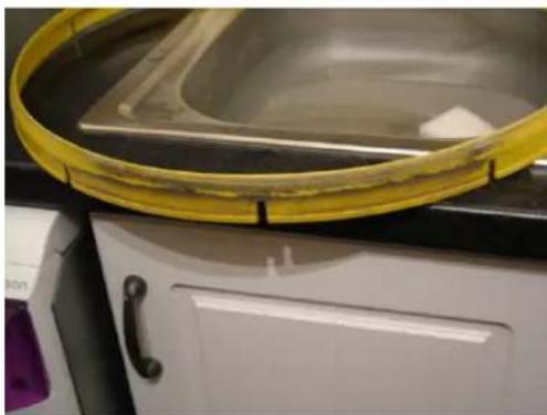
Circular mechanical component with segmented rings on a textured floor (no visible text or symbols)13) Remove front door seal. This can be pulled of very easily and should be cleaned prior to refitting. If damaged replace as spares as still available.
14) Remove the plastic protection ring. This is held in with double sided tape and can be gently pulled off and re-fixed in the same manner.
Plastic Protection Ring
natural_image
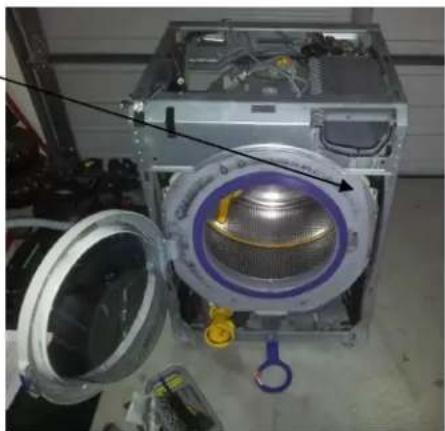
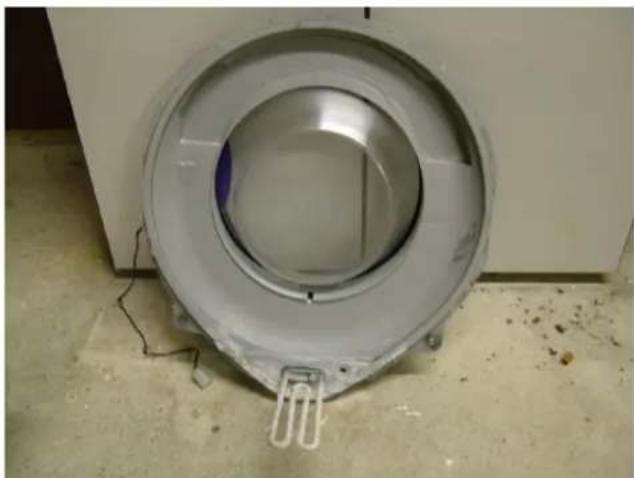
Interior view of a washing machine with visible internal components and a blue handle (no text or symbols)15) Remove the heater element
16) Remove front tub assembly. This part includes the front door and the tub front. It does not need disassembled further however you may wish to replace the element while you have it out.
A) Firstly disconnect the door lock cable
B) Remove the two bolts that attach the front tub assembly to the shock absorbers. As you do this the two nuts attached to these bots will fall into the base of the machine.
C) Remove tub pressure sensor pipe
Door lock cable.
When everything has been removed, gently pull front tub assembly clear of the tub. I chose to leave the heater element in place and if you do likewise, care should be taken not to damage it.
natural_image
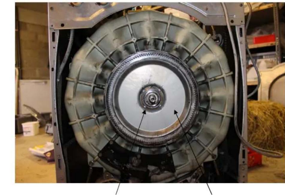
Circular metallic device mounted on a wall, showing internal components and wiring (no text or symbols visible)17) Remove Drum securing Nut. You will find a lot has been written on how to remove this nut and if you can find or manufacture the correct tool then go that way. The nut is a normal right hand thread so there is no surprise there. I found that it can be loosened very easily if you hit it very hard with a large hammer and bolster. Do not tickle it or all you will do is damage to the nut.
natural_image
Interior view of a mechanical assembly with visible gears and components, no text or symbols present.Drum Securing Nut Gear Plate
18) Remove gear plate. This should just pull over the centre shafts
natural_image
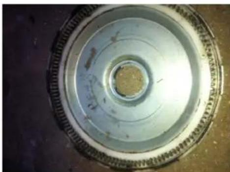
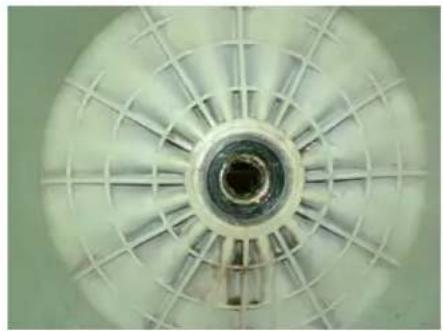
Circular mechanical component with concentric rings and central hole, no visible text or symbols19) Remove the drum assembly from the front of the machine. This should pull out very easily and is not heavy. (Image is of a cleaned repaired drum)
natural_image
Close-up of a mechanical component with internal gears and mounting base (no visible text or symbols)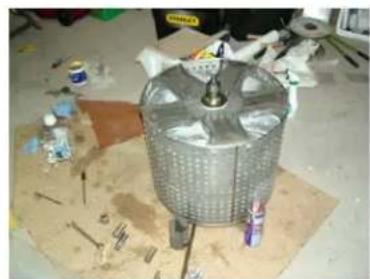
natural_image
Metal cylindrical mechanical component on a workbench with scattered paint and tools (no visible text or symbols)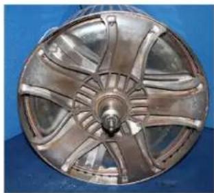
natural_image
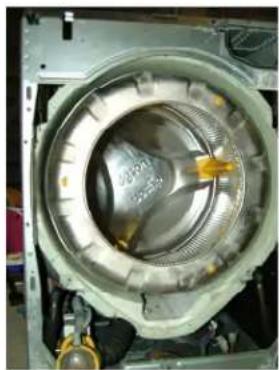
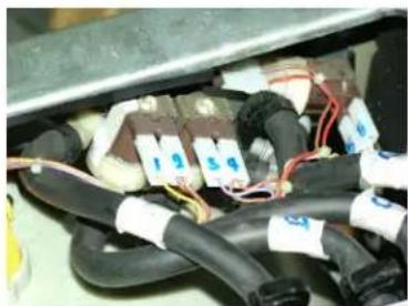
Close-up of a metallic turbine or impeller component with radial blades and central hub against a blue background (no text or symbols visible)20) Remove Soap Dispenser and Water Solenoids. First gently release the from of the soap dispenser by prising back the retaining tab. This will allow you move it and give you access to the 2 rubber pipes that connect it to the drum. There after remove the four screws at the rear of the machine which hold the filling hose connectors in place. Mark all the electrical terminal so the re-fitting will be easier and photograph just in case.
natural_image
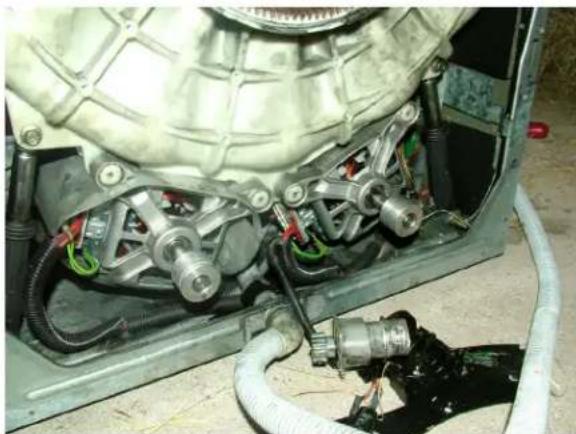
Close-up of electrical wiring and components in a mechanical assembly (no visible text or symbols)21) Remove both Motors, Contra-Rotate Motor and Rear shocker screws.. The motors are held on with 4 screws and fit tightly onto there retaining bracket. I found that a gentle tap with a rubber hammer at the rear loosened them enough to slide off. There is no need to mark the electrical connection as they only fir one way. The
contra-rotate gear drive motor is removed with 5 torx head screws. It can then be disconnect from its push connector at the base of the machine.
natural_image
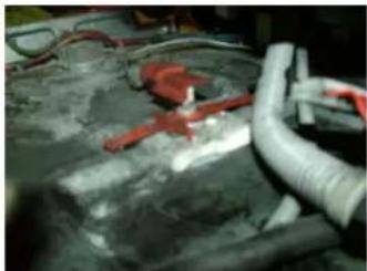
Close-up of a mechanical assembly with hoses and wiring, no visible text or symbols22) Remove flow check micro switch and float. This is located in the base of the machine and it very fragile. It is held in place with two tabs that need to be released under the machine. You will need help or something to balance the machine. Once the tabs are release it can be disconnected from its electrical connector.
natural_image
Close-up of industrial piping and valves on a concrete surface (no visible text or symbols)23) Disconnect the waste pump from the base of the machine. I found it was okay just to remove the connecting rubber hose and leave the pump in situ.
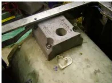
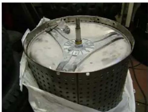
24) Remove the top weight from the tub and the two yellow sensors. The weight is held on with four screw and after they are removed need prised off it locating pegs. I also marked each senor so they could be re-fitted in the same place. The can be left hanging at the rear of the machine.
natural_image
Close-up of a metallic mechanical component with a circular hole and small part, placed on a concrete surface (no visible text or symbols)25) Remove the Tub. The tub should now be held in with the 4 suspension springs which are easily removed. (check in case I missed something). I found the tub came out the back very easily,
DRUM
26) Remove Torx screws that secure the drum to the 5 point spider. They are T40 which are held into the spider with thread lock. In addition corrosion will have taken place between spider and the bolt thread. Out of the 10 I managed to remove 6 using freeze release oil and heat from a heat gun but the heads of the other four broke off. Start by tightening the bolts and then un-tightening. Slowly you will get movement but it is time consuming and frustrating. You do not need to remove the bolts from the 3 point spider on the inner drums. Thanks to Daniel Marsh for these tips
natural_image
Close-up of a metallic mechanical component with perforated surface and central hub (no visible text or symbols)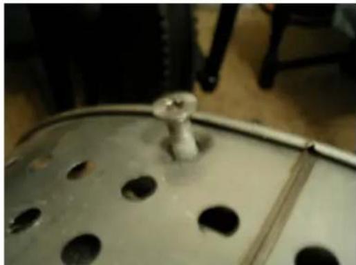
natural_image
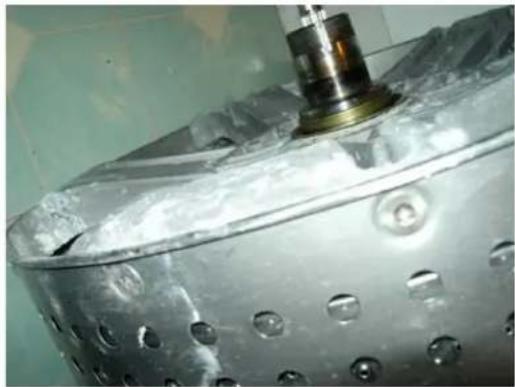
Close-up of a metallic cylindrical object with circular holes, placed on a curved surface (no visible text or symbols)27) Remove the 5 point spider from the drum assembly. You will see that the holes on the drum are countersunk and they fit into countersunk holes on the spider. In addition there will have been corrosion between the drum and the spider, as such the spider will almost be welded to the drum. Firstly I broke the corrosion using a palate knife then using a number of flat headed screwdrivers, I gently prised out the spider from the drum. The inner drum may come with the spider but that can be gently prised away.
natural_image
Metal perforated cylindrical device with internal components, placed on a white cloth (no visible text or symbols)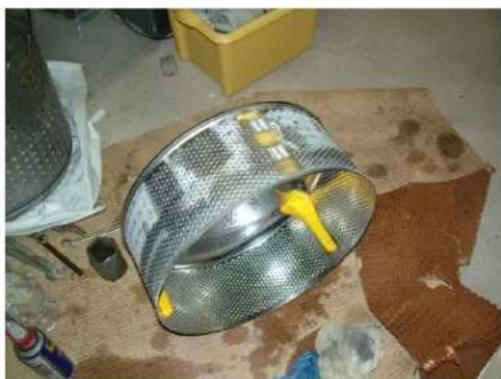
natural_image
Metal mesh filter with yellow adhesive being placed on a textured floor, no visible text or symbols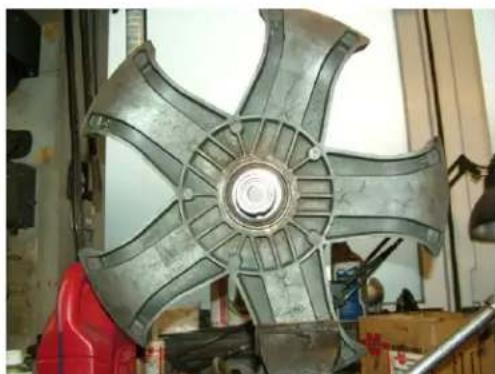
natural_image
Metal mechanical component with six arms, displayed indoors near a red vehicle (no visible text or symbols)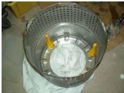
natural_image
Metal basket containing white cloth with yellow plastic components, placed on a cloth (no text or symbols visible)Now it's time to start removing the bearings and cleaning the drum components
28) The spider has two bearings and a rubber seal. All can be removed very easily with a hammer and screw driver. The seal on my spider had failed however the bearings were still sound, never the less I decided to replace them and hopefully avoid dismantling again. If you zoom into the image you will see that there are still four bolts broken within the spider. DO NOT BE TEMPTED TO USE HARDEN STEEL EZ- OUT BITS to remove the broken bolts. You will almost certainly break the bit which gives you an even bigger headache. Trust me that's what happens. In the end I drilled out the broken bolts and also the threads from the other six holes which were later re-secured with stainless nuts and bolts.
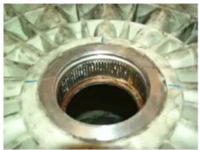
29) Remove the slip ring from the inner drum. Thoroughly clean it and the mating surface within the outer drum.
natural_image
Close-up of a kitchen appliance with a yellow lid and white cabin (no visible text or symbols)30) Check bearing and seal within the tub. Initially I thought the main bearing to be okay but the tub seal had gone and that made it only a matter of time until the bearing failed as well. The seal was easily removed with a screw driver and the seal locating hole cleaned. When I removed the seal I saw it was stamped RWDR-KONBI 70x100x10.5/14.5, I bought a replacement 70x100x10 but found this rubbed against the brass seal on the main shaft. Closer inspection of the removed seal showed that the inner part of the seal was stepped back by 2mm. Unfortunately I could not source the original seal so opted for a 70x100x8 mm seal.
31) Remove the main bearing. There is a retaining circlip which is easily removed, however the bearing was a different matter. Try as a might with a sliding hammer and a tool I made from steel I could not budge it. I eventually resorted to calling in a favour and having the bearing pressed out using a hydraulic press. It took a fare bit of pressure to remove the bearing and caused a bit of stress to the plastic around the bearing housing. The new bearing was pressed in using the same machine
natural_image
Close-up of a metallic mechanical component with a central hole and surrounding gear-like structure (no visible text or symbols)When everything is clean and free from rust, lime scale and debris then it's time to re-assemble your CR01
You will need the following parts
TUB SEAL - 1 - 70x100x8mm Nitrile Rubber Rotary Shaft Oil Seal with Garter Spring.
From www.bearingstation.co.uk
TUB BEARING - 1-633007c bearing (90x50x34)
From www.ebay.co.uk (rracingaviation)
INNER DRUM BEARING 1 - STAINLESS STEEL BEARING SS-6904-2RS-MTK INNER DRUM METRIC OIL SEAL - 34X52X10_R23_NITRILE
All from www.engineersmate.com
INNER DRUM BEARING 2- DEEP GROOVE BALL BEARINGS 6205 2RS
www.bearing-king.co.uk
DRUM SECURING BOTS
NUT - 1 x M8 Square Nut DIN 557 A2 Multipack 20 (Thick profile (DIN 557)) BOLT - 10 x M8 T40 torx counter sunk stainless steel bolts.
If you use nuts and bots the nuts will need locked with thread
All from www.a2stainless.co.uk
Thread lock - Loctite 243 Lock n Seal.
Grease - Large tub multi purpose grease
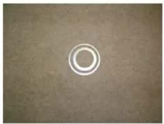
Spacers – These are used to make up for the difference in 2mm thickness of the original bearing at the replacement. I ordered two
a) 89.5x80x2
b) 67x50.5x2
natural_image
Circular white ring on a textured gray background (no text or symbols)These should be in stainless steel and can be sourced from
www.lasermaster.co.uk
32) Fit new Tub bearing. You will see from the bearing housing photograph at 25, that the retaining edge is quite badly rusted. This should be cleaned and spacer 'A' placed in the hole prior to the new bearing being pressed in. This will allow the bearing to sit in its proper position relative to the circlip. Refit the circlip and press the new seal into place. Make sure the seal goes as far back as it can or it will rub against drum shaft.
natural_image
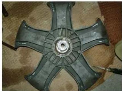
Close-up of a circular fan or turbine blade with radial blades and central bore (no text or symbols visible)Before
natural_image
Close-up of a circular fan or impeller with radial blades and central hub (no text or symbols visible)After
33) Press the new bearings and seal into the five point spider. Using a hammer and appropriate sized socket you risk damaging the bearing.
natural_image
Close-up of a metallic mechanical component with six blades, no visible text or symbols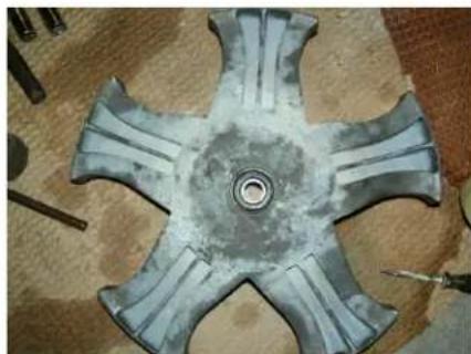
natural_image
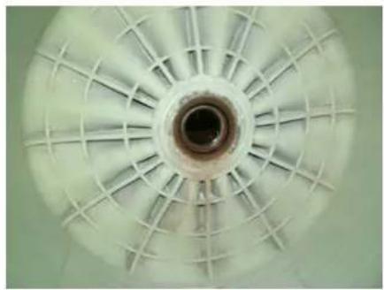
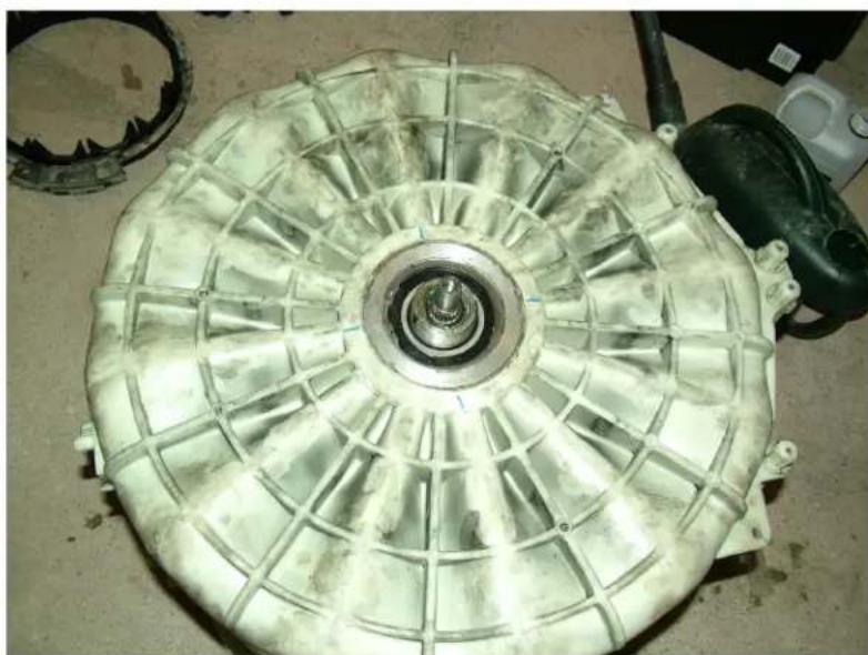
Top-down view of a metallic mechanical component with five arms and central hub, surrounded by tools and materials on a wooden surface (no text or symbols visible)34) Fit the drum into the tub. Spacer 'B' should be fitted over the shaft first as this will maintain the geometry of the assembly with spacer 'A'. Although this makes it heavier to refit into the machine it makes it so much easier to guarantee a tight seal on the nut.
natural_image
Top-down view of a large industrial fan or turbine component with visible internal structure and central hub (no text or symbols)When the bearings are fitted reassemble in reverse and good luck
Brand : DYSON
Model : CR01 Flowcheck
Category : Washing machine