
EP5024K - Monitor Planar - Free user manual and instructions
Find the device manual for free EP5024K Planar in PDF.


User questions about EP5024K Planar
0 question about this device. Answer the ones you know or ask your own.
Ask a new question about this device
Download the instructions for your Monitor in PDF format for free! Find your manual EP5024K - Planar and take your electronic device back in hand. On this page are published all the documents necessary for the use of your device. EP5024K by Planar.
USER MANUAL EP5024K Planar
EP Series Ultra HD LCD Displays User Guide
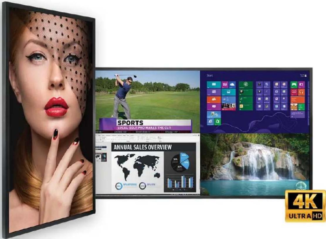
text_image
SPORTS LOCAL GOLE PRO MAKES THE CUT ANNUAL SALES OVERVIEW 4K ULTRA HDEP5024K
EP5024K-T
EP5824K
EP5824K-T
EP6524K
EP6524K-T
Copyright © 5 Jan 2018 by Planar Systems, Inc. All rights reserved.
Contents of this publication may not be reproduced in any form without permission of Planar Systems, Inc.
Trademark Credits
Windows ^™ is a trademark of Microsoft Corp.
All other companies are trademarks or registered trademarks of their respective companies.
Disclaimer
The information contained in this document is subject to change without notice. Planar Systems, Inc. makes no warranty of any kind with regard to this material. While every precaution has been taken in the preparation of this manual, the Company shall not be liable for errors or omissions contained herein or for incidental or consequential damages in connection with the furnishing, performance, or use of this material.
Warranty and Service Plans
Planar warranty and service plans will help you maximize your investment by providing great support, display uptime, and performance optimization. From post-sale technical support to a full suite of depot services, our services are performed by trained Planar employees. When you purchase a Planar product, you get more than a display, you get the service and support you need to maximize your investment. To find the latest warranty and service information regarding your Planar product, please visit http://www.planar.com/support
Part Number: 020-1346-00A
Contents
EP Series Ultra HD LCD Displays User Guide ...... i
Introduction 1
Safety Information ....2
Safety Precautions....2
Recommended Usage 4
VESA Mounts, General Description....6
Cleaning the Display ....7
Package Contents....8
Installing the Cable Clips 10
Planar EP Series - Standard Inputs.... 11
Installing the Display 12
Before You Begin.... 12
Installing OPS Expansion (Optional).... 14
Operating the Display 15
OSD Keypad.... 15
Remote Control Receiver 16
Installing IR Extender 17
LED Indicators.... 18
Using the Display in Portrait Mode 18
Using the Display in Flat or Tilted Orientation 18
Using the Remote Control 19
Turning the Display On 22
Turning the Display Off....23
Adjusting the Volume 23
Selecting the Input Source.... 23
Navigating Through the Menus....23
Using the Touch Screen 47
LAN Control 48
Supported Operating Systems 48
Installation.... 49
Configuring VCOM 52
Function Descriptions 54
Setting Up Email Alerts 58
Login 58
Administrator 60
TCP Mode, UDP Mode and UART 63
SMTP 63
Reset Device 64
Signal Compatibility 65
Color Subsampling Support 68
Specifications 69
Dimensions 71
EP5024K 71
EP5024K-T 72
EP5824K 73
EP5824K-T 74
Table of Contents
EP6524K....75
EP6524K-T 76
Troubleshooting....77
Accessing Planar's Technical Support Website....78
Introduction
The Ultra HD resolution Planar EP Series LCD displays offer best-in-class reliability with the stunning image quality of 4K resolution. The displays come standard with commercial-grade features - such as 4K@60Hz support through both HDMI and DisplayPort and HDCP 2.2 compliance - which are required for digital signage, corporate, and control room environments.
Also available in touch versions, Ultra HD Planar EP Series displays bring interactivity to the 4K immersive experience.
Caution: This manual is intended for use by qualified service persons and end users with experience installing LCD displays.
Safety Information
Before using the Planar EP Series, please read this manual thoroughly to help protect against damage to property, and to ensure personnel safety.
- Be sure to observe the following instructions.
- For your safety, be sure to observe ALL the warnings detailed in this manual.
- For installation or adjustment, please follow this manual's instructions, and refer all servicing to qualified service personnel.
Safety Precautions
- If water is spilled or objects are dropped inside the display, remove the power plug from the outlet immediately. Failure to do so may result in fire or electrical shock. Contact your dealer for inspection.
- If the display is dropped or the chassis is damaged, remove the power plug from the outlet immediately. Failure to do so may result in fire or electrical shock. Contact your dealer for inspection.
WARNING! Wall mounts must be secure.
- If the display is hung on a wall, the wall must be strong enough to hold it. Simply mounting it to wallboard or wall paneling won't be adequate or safe.
Caution: The screen could be damaged by heavy pressure.
- Slight pressure on the LCD will cause distortion of the image. Heavier pressure will cause permanent damage. Displays should be mounted where viewers cannot touch the screen or insert small objects in the openings that will create hazards by contacting bare conductive parts.
Caution: The front polarizer is soft and subject to scratches from sharp objects.
- The polarizer is a thin sheet of film laminated to the outside layer of glass on the LCD screen. Take care when handling items near the screen.
- If the power cord or plug is damaged or becomes hot, turn off the main power switch of the display. Make sure the power plug has cooled down and remove the power plug from the outlet. If the display is still used in this condition, it may cause a fire or an electrical shock. Contact your dealer for a replacement.
Important Safety Instructions
1 Read these instructions.
2 Keep these instructions.
3 Heed all warnings.
4 Follow all instructions.
5 Do not use the display near water.
6 Clean the LCD screens with an LCD screen cleaner or LCD wipes.
7 Do not install near any heat sources such as radiators, heat registers, stoves or other apparatus (including amplifiers) that produce heat.
8 Do not defeat the safety purpose of the polarized or grounding type plug. A polarized plug has two blades with one wider than the other. A grounding type plug has two blades and a third grounding prong. The wide blade or the third prong is provided for your safety. When the provided plug does not fit into your outlet, consult an electrician for the replacement of the obsolete outlet.
9 Protect the power cord from being walked on or pinched, particularly at plugs, convenience receptacles and the point where they exit from any of the displays.
10 Only use the attachments/accessories specified by the manufacturer.
11 Unplug all displays during lightning storms or when unused for long periods of time.
12 You must follow all National Electrical Code regulations. In addition, be aware of local codes and ordinances when installing your system.
13 Refer all servicing to qualified service personnel. Servicing is required when any of the displays have been damaged in any way. For example, if the AC power cord or plug is damaged, liquid has been spilled or objects have fallen into a display, the displays have been exposed to rain or moisture, do not operate normally or have been dropped.
14 Keep the packing material in case the equipment should ever need to be shipped.
15 Wall mounts must be secure. The wall must be strong enough to hold all displays, brackets and cables.
16 Slight pressure on the LCD will cause distortion of the image. Heavier pressure will cause permanent damage. Displays should be mounted where viewers cannot touch the screen or insert small objects in the openings that will create hazards by contacting bare conductive parts.
17 The front polarizer is soft and subject to scratches from sharp objects. The polarizer is a thin sheet of film laminated to the outside layer of glass on the LCD screen. Take care when handling items near the screen.
Recommended Usage
In order to get the most out of your LCD, use the following recommended guidelines to optimize the display.
Burn-In Versus Temporary Image Retention
Burn-in causes the screen to retain an image essentially forever, with little or no way to correct the problem. Under normal use, an LCD will not experience burn-in, as plasma displays do, nor will it retain images in any way.
Normal use of an LCD is defined as displaying continuously changing video patterns or images. However, LCDs can experience temporary image retention when recommended usage guidelines are not followed.
What is Temporary Image Retention?
Temporary image retention (TIR) can occur when a static image is displayed continuously for extended periods of time (12 hours or longer). An electrical charge differential may build up between the electrodes of the liquid crystal, which causes a negative-color video image (color-inverted and brightness-inverted version of the previous image) to be retained when a new image is displayed. This behavior is true for any LCD device from any LCD manufacturer.
TIR is not covered under warranty. See standard warranty terms and conditions for details. Here are some guidelines to help you avoid TIR:
- Use the LCD to show a screen saver, moving images or still pictures that change regularly. When using high-contrast images, reposition the images frequently.
- Turn off the LCD when it is not in use. To use your source computer's Power Options Properties, set up your computer to turn off the display when not in use.
Warranty Coverage
The following models are warranted for 24 x 7 usage:
- 50": EP5024K, EP5024K-T
- 58": EP5824K, EP5824K-T
• 65": EP6524K, EP6524K-T
Planar recommends turning off the power for 4 hours per day for optimal performance.
For complete warranty details, please visit www.planar.com/warranty.
Important Waste Disposal Information
Please recycle or dispose of all electronic waste in accordance with local, state, and federal laws. Additional resources can be found online at http://www.planar.com/about/green/.
The crossed-out wheelie bin symbol is to notify consumers in areas subject to Waste Electrical and Electronic Equipment (WEEE) Directive 2012/19/EU that the product was placed on the market after August 13, 2005 and must not be disposed of with other waste. Separate collection and recycling of electronic waste at the time of disposal ensures that it is recycled in a manner that minimizes impacts to human health and the environment. For more information about the proper disposal of electronic waste, please contact your local authority, your household waste disposal service, or the seller from whom you purchased the product.

Normal Usage Guidelines
Normal use of the LCD is defined as operating in the open air to prevent heat buildup, and without direct or indirect heat sources such as lighting fixtures, heating ducts, or direct sunlight that can cause the modules to experience high operating temperatures. For all modules, do not block fans or ventilation openings. If the LCD module will be installed in a recessed area with an LCD surround or enclosure, ensure adequate openings are applied for proper air flow and ventilation.
At 3000 meters or below, the maximum ambient operating temperature for the LCD module cannot be above 40^ C nor below the minimum ambient operating temperature of 0^ C. If one of these conditions exists, it is up to the installer to ensure that module placement is changed, thermal shielding is provided and/or additional ventilation is provided to keep the display within its nominal operating parameters.
Cooling Requirements
For optimal performance, active cooling by the installer should be planned for when the ambient temperature at the top of the wall is predicted to be above the specified ambient temperature for the panel. Cooling may be done behind the displays and depending on the wall configuration, it may be helpful to place air ducts (AC) at every third display tall.
VESA Mounts, General Description
VESA mounts are used to secure the Planar EP Series for display. The display can be installed using a variety of VESA mounts available through Planar. If you do not have a VESA mount and would like to purchase one, contact Planar.
If you purchased a VESA mount, you should have a received a separate box with mounting supplies and an Installation manual. Follow these instructions carefully.
Keep in mind the following general installation guidelines:
- Screw length is crucial and will vary depending on the type of mount you use. Total screw length will include the penetration length plus the length required by the type of VESA mount in use.
- Mount spacers may be required to accommodate the protruding back panel of the OPS slot.
Caution: Shorter screws will result in insufficient mounting strength and longer screws could puncture parts inside the display.
- Prior to installation, make sure you know where all of the mounting points are located.
- Follow all safety precautions outlined in the VESA Installation manual.
- Verify the parts received with the list shown in the VESA Installation manual.
Cleaning the Display
If dust has collected on the power plug, remove the plug from the outlet and clean off the dust. Dust build-up may cause a fire.
Remove the power plug before cleaning. Failure to do so may result in electrical shock or damage.
Keep the following points in mind when cleaning the surface of the display:
- When the surface of the display becomes dirty, wipe the surface lightly with a soft clean cloth.
- If the surface requires additional cleaning, use LCD screen cleaner or LCD wipes, which are available at most electronics stores.
- Do not let cleaner seep into the display, as it may cause electrical shock or damage.
Package Contents
| Part Description Number Picture | ||
| LCD display One per box. 1 |  | |
| HDMI cable HDMI cable. 1 | 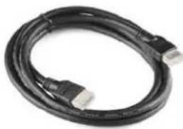 | |
| USB cable Connects to a PC for touch functionality (touch models only). | 1 | 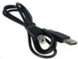 |
| AC power cord | Power cord. 1 | 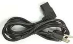 |
| IR extender cable | Used to receive signals from the remote control. | 1 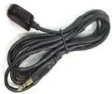 |
| Remote control | Used to control the display (AAA batteries included). | 1 | 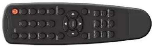 |
| Cable clips Used to clamp and organize the cables. | 2 | 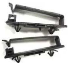 | |
| TouchMark License Key | TouchMark License Key (touch models only). | 1 |  |
| Quick Start Guide | Quick Start Guide. 1 |  | |
Installing the Cable Clips
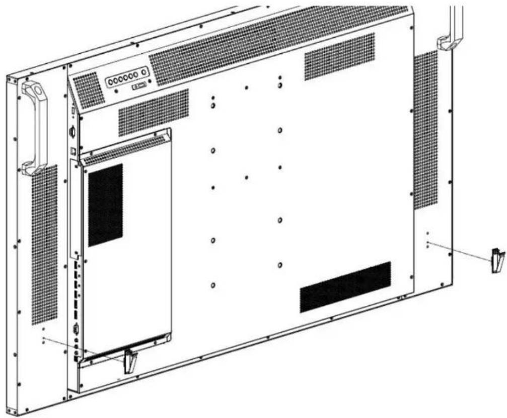
The cable clips included in the Accessory Kit are used to assist with cable management. These clips snap into place as shown in the image below.
natural_image
Technical line drawing of a server rack unit with mounting brackets and ventilation grilles (no text or symbols)Planar EP Series - Standard Inputs
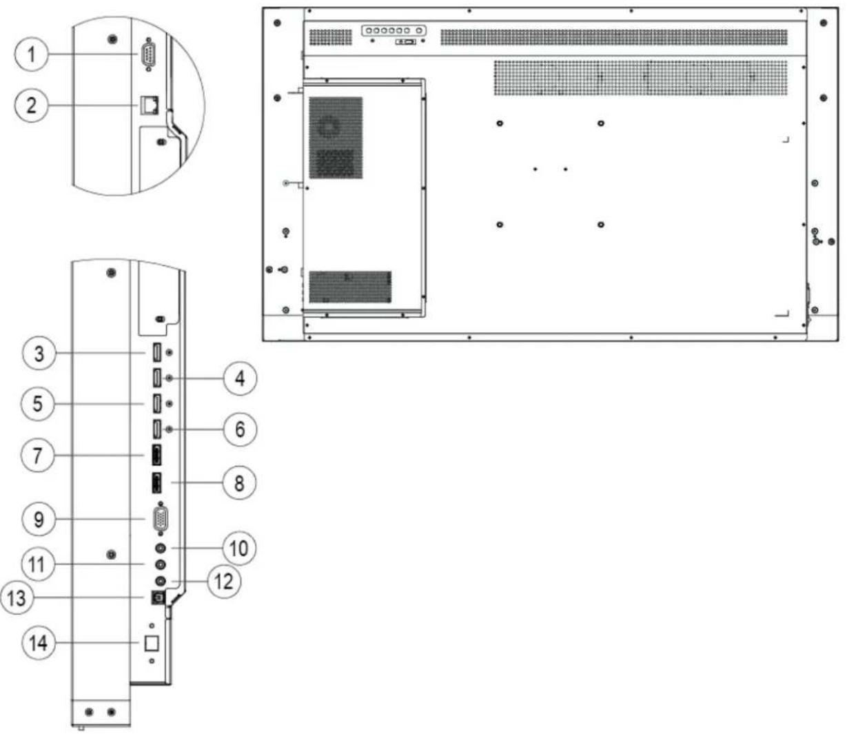
| 1 | R | S | 2 | 3 | 2 | I | n | 8 | D | P | 2 |
| 2 | L | A | N | 9 | V | G | A | ||||
| 3 | H | D | M | I | 1 | 1 | 0 | P | C | A | u |
| 4 | H | D | M | I | 2 | 1 | 1 | I | R | ||
| 5 | H | D | M | I | 3 | 1 | 2 | A | u | d | i |
| 6 | H | D | M | I | 4 | 1 | 3 | S | P | D | I |
7 DP 1 14 Touch USB (Touch models)
Installing the Display
This section explains how to install your display. We suggest that you read the entire section before you attempt to install the unit.
Before You Begin
Make sure you have all the items in these lists before you begin unpacking and installing your display(s).
Tools/Equipment List
Depending on your installation, you may need one or more of the following items:
- String/string level
- Digital/laser level
- Ladders/lift
- Back brace
- Stud finder (if hanging display on a wall)
Other Things You May Need
- LCD screen cleaner or LCD wipes - available at most electronics stores
- At least two very strong people to help lift units into place
Plan Your Installation
You should have a detailed plan of how the units are to be configured. The plan should include calculations for the following:
• Power (maximum of five units per 20A circuit for 115V operation)
- Cable runs
- Ventilation and cooling requirements
- If hanging display on a wall, location of studs in the wall
Prepare Your Installation Location
You should have prepared the area where you will install the unit. If custom enclosures are part of the installation, they must be fully designed to accommodate the installation of the displays, as well as the installed unit and ventilation and cooling requirements.
If your installation included a lot of construction or dust, it is highly recommended that you clean all of the screens after the wall installation and configuration are complete.
Cable Length Recommendations
Cable length performance may vary between different cables and sources. The recommended maximum cable lengths are as follows:
HDMI
• 4K @ 50/60Hz: 8m (25 ft) maximum
• 4K @ 24/25/30Hz: 15m (50 ft) maximum
- 1080p @ 60Hz and lower resolutions: 20m (65 ft) maximum
DisplayPort
• DP 1.2: 5m (15 ft) maximum
• DP 1.1: 8m (25 ft) maximum
Installing OPS Expansion (Optional)
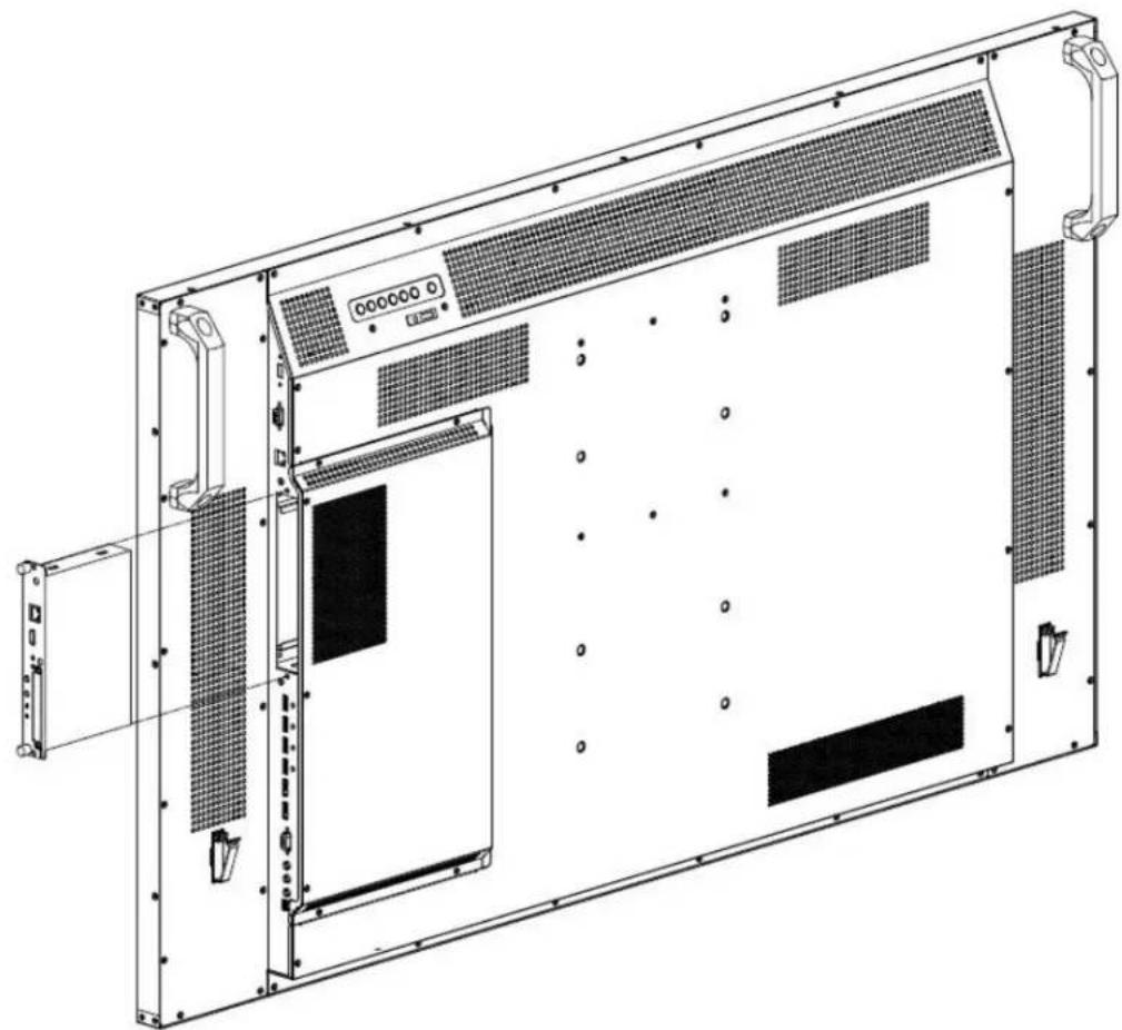
The Planar EP Series displays are equipped with an expansion slot that supports the Intel® Open-Pluggable Specification (OPS). The slot will support OPS devices such as PC's, SDI modules etc.
To install an OPS device, remove the protective cover on the display and slide the device firmly into position. When installed, the OPS device will be connected internally to the display. No external video or power cables are required.
For convenience, two Type-A USB 2.0 ports and one Type-A USB 3.0 port are provided on the rear cover of the display. When an OPS device is installed, these USB ports can be used for a keyboard, webcam, USB drive, or other peripherals.
natural_image
Technical line drawing of an internal server or rack unit with ventilation grilles and mounting brackets (no text or symbols)Operating the Display
OSD Keypad
The OSD keypad is located on the rear of the display.
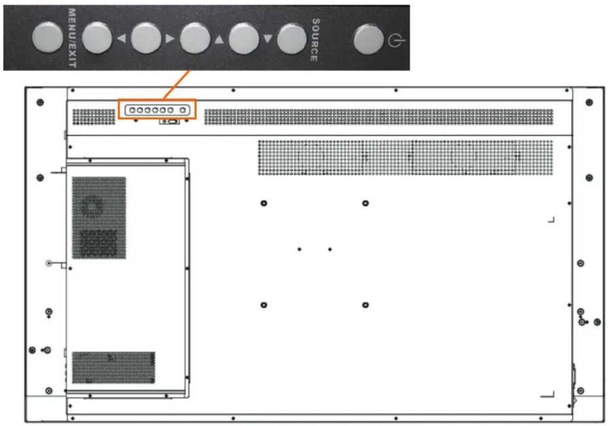
text_image
MENU/EXIT SOURCEOSD Keypad Buttons
| Key Descriptions | |
| Power Power on/Power off | |
| Source Source selection (toggle) | |
| ► Menu Right/Increase value | |
| ◄ Menu Left/Decrease value | |
| ▲ | Menu Up |
| ▼ Menu Down | |
| Menu/Exit Menu/Exit | |
Remote Control Receiver
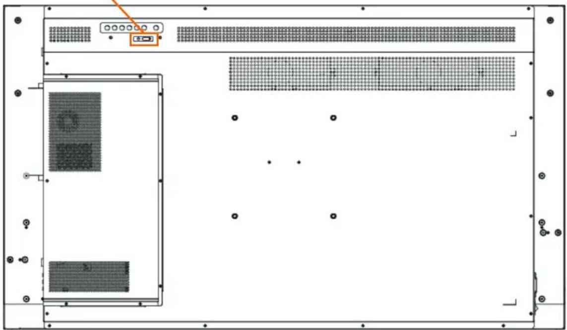
The remote control receiver is located near the keypad on the rear of the display. Use the IR extender cable for operating the remote from the front of the display.
Power ON standby indicator, Remote control receiver
natural_image
Front view of a computer rack unit with indicator lights and drive bays (no text or symbols visible)Installing IR Extender
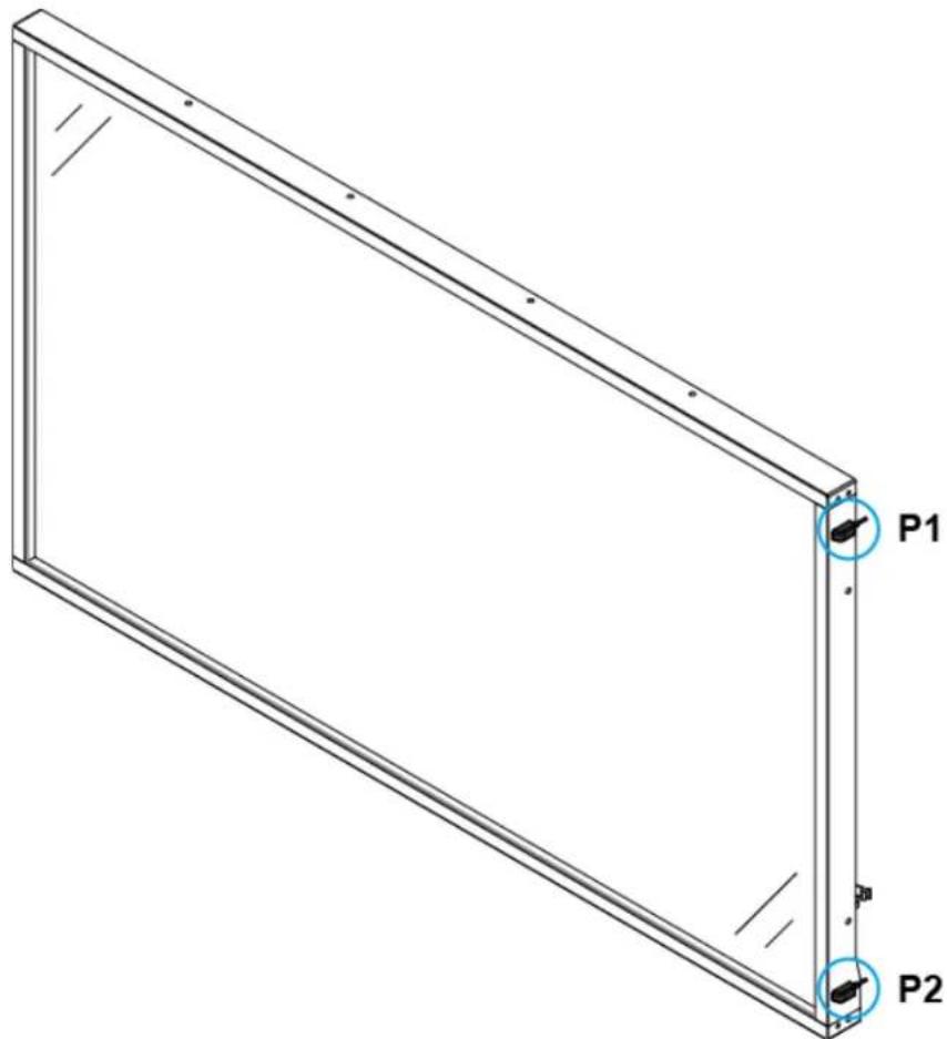
The position of the IR extender will affect the reception of the IR signal. To ensure the best IR reception, P1 and P2, the two positions marked in the figure below, are recommended for installing the IR extender.
text_image
P1 P2LED Indicators
The LED indicator light is located on the rear of the display near the keypad. The following table explains what the different colors and blink patterns mean.
LED On
| Power Status Condition | |
| Green Power | on |
| Blinking Orange No signal | |
| Orange Power | saving mode |
| Off AC off | |
| Off Power off | |
Using the Display in Portrait Mode
When using the display in the portrait position and looking at the rear of the display, it should be rotated according to the arrow stickers on the back of the display. This will allow for proper ventilation. Then select the OSD rotation of landscape or portrait on the OSD menu (MAIN MENU > OSD SETTINGS > OSD ROTATION).
Caution: Improper ventilation may shorten the life of the display.
Using the Display in Flat or Tilted Orientation
The display is not recommended for use in flat orientation for tabletop, floor, or ceiling installations. LCD panels of this size are at risk of panel deflection, which can cause cosmetic sagging, brightness uniformity issues, a shortened life span, and malfunction of optional touch sensors. Installations where the display is tilted downward or upward at an angle may also be prone to these issues and are not recommended.
Using the Remote Control
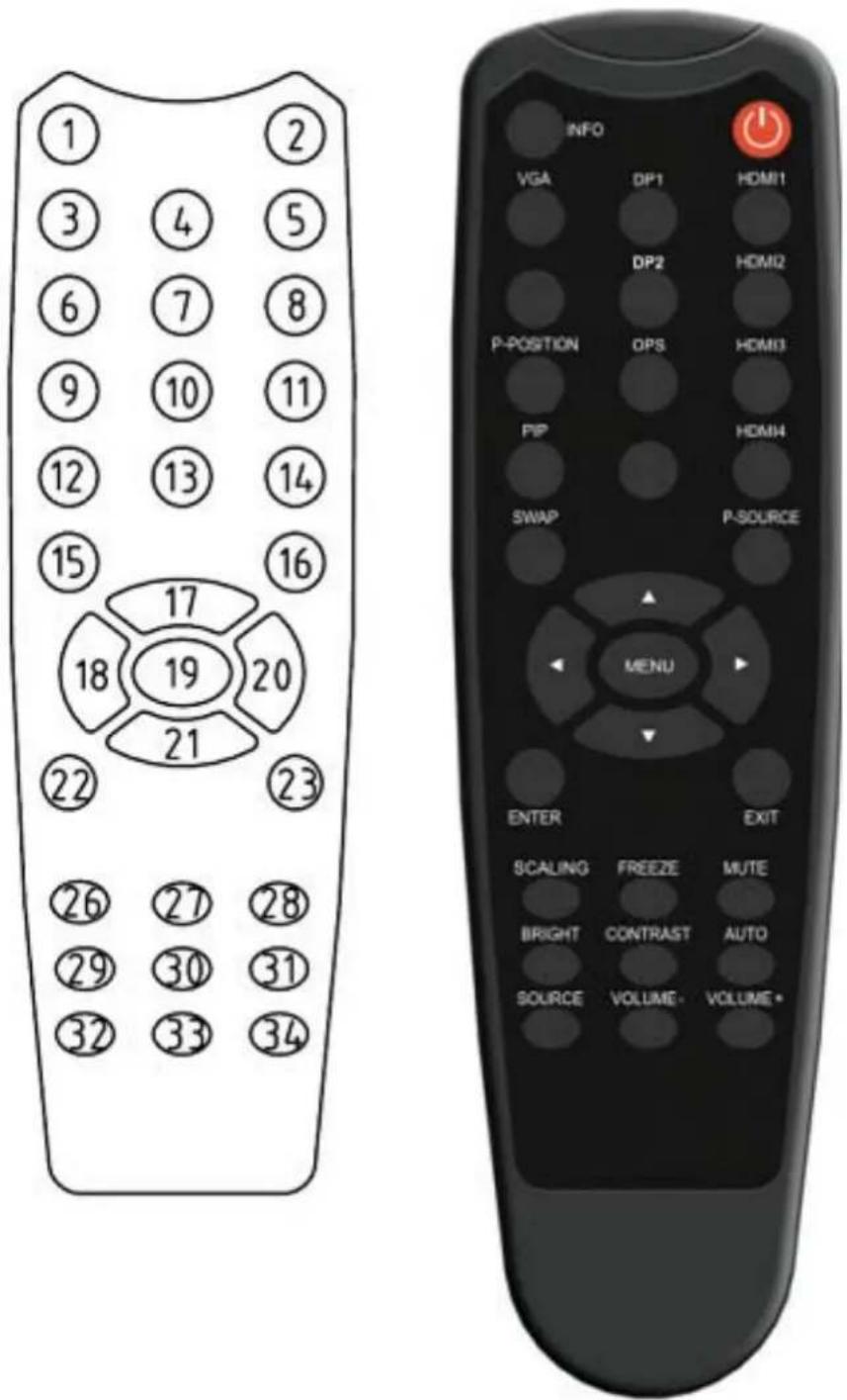
Below is a picture of the remote control and its corresponding Hex codes. See the following page for button descriptions and Hex codes.
text_image
1 2 3 4 5 6 7 8 9 10 11 12 13 14 15 16 17 18 19 20 21 22 23 26 27 28 29 30 31 32 33 34 INFO VGA DP1 HOM11 DP2 HOM2 P-POSITION OPS HOM3 PIP HOM4 SWAP P-SOURCE MENU ENTER EXIT SCALING FREEZE MUTE BRIGHT CONTRAST AUTO SOURCE VOLUME- VOLUME- INFO| Num Function | Customer Code | Hex Code Description | |
| 1 | INFO | 40AF | 04FB Provides source and resolution information |
| 2 | 40AF 1CE3 Turns the display on and off | ||
| 3 | VGA | 40AF 07F8 Selects the VGA source | |
| 4 | DP1 | 40AF 08F7 Selects the DP1 source | |
| 5 | HDMI1 | 40AF 09F6 Selects the HDMI source 1 | |
| 6 | Not used | ||
| 7 | DP2 | 40AF 0BF4 Selects the DP2 source | |
| 8 | HDMI2 | 40AF 0CF3 Selects the HDMI source 2 | |
| 9 | P-position | 40AF 1AE5 Selects the PiP (Picture-in-Picture) position | |
| 10 | OPS | 40AF 15EA Selects the OPS source | |
| 11 | HDMI3 | 40AF 10EF Selects the HDMI source 3 | |
| 12 | PIP | 40AF 11EE Selects the Multi-Source View | |
| 13 | Not used | ||
| 14 | HDMI4 | 40AF 16E9 Selects the HDMI source 4 | |
| 15 | SWAP | 40AF 06F9 Swaps the main input source with source 2 | |
| 16 | P-SOURCE | 40AF 13EC Selects the PiP (Picture-in-Picture) source | |
| 17 | ▲ | 40AF 02FD Navigates up through submenus and settings | |
| 18 | 40AF 01FE Navigates back through submenus and settings | ||
| 19 MENU | 40AF 0EF1 Opens the display's on-screen menu system. When the menu system is already open, pressing this button will select the previous submenu. | ||
| 20 | 40AF 03FC Navigates forward through submenus and settings | ||
| 21 | 40AF 19E6 Navigates down through submenus and settings | ||
| 22 | ENTER | 40AF 12ED Selects highlighted menu choices | |
| 23 | EXIT | 40AF 05FA Closes the menu system | |
| 26 | SCALING | 40AF 14EB Toggles between different aspect ratios (Auto, Native, 4 x 3, Full Screen and Letterbox) | |
| 27 | FREEZE | 40AF 43BC Freezes the current source image | |
| 28 | MUTE | 40AF 00FF Turns off the sound | |
| 29 | BRIGHT | 40AF 17E8 Adjusts the brightness | |
| 30 | CONTRAST | 40AF 18E7 Adjusts the contrast | |
| 31 | AUTO | 40AF 1EE1 Synchronizes the display to the source | |
| 32 | SOURCE | 40AF 0FF0 Allows selection of the different sources | |
| 33 | VOLUME - | 40AF 1BE4 Decreases the sound volume | |
| 34 | VOLUME + | 40AF 1DE2 Increases the sound volume | |
Locking/Unlocking the OSD Menus
You can lock or unlock the OSD menus by pressing a series of key commands on the remote control. To lock the menu, press the following keys on the remote in the order listed: ENTER, ENTER, EXIT, EXIT, ENTER and EXIT. To unlock it, simply follow the same sequence.
Depending on whether you locked or unlocked the menu, you will see one of the following messages on the screen.
Key Unlocked
Key Locked
Changing the Remote Control Battery
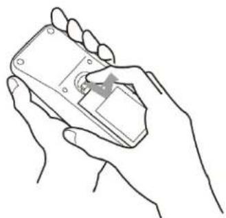
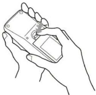
1 Remove the battery cover.
Slide back and remove the battery cover in the direction of the arrow.
natural_image
Line drawing of a hand holding a remote control device (no text or symbols)2 Insert the batteries.
Align and insert two AAA batteries according to their plus and minus ports (as indicated in the remote control).
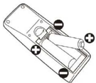
natural_image
Technical line drawing of a remote control box with mounting holes and indicator lights (no text or symbols)3 Close the battery cover.
Replace the battery cover in the direction of the arrow and snap it back into place.
natural_image
Line drawing of a hand holding a handheld device (no text or symbols)Turning the Display On
1 Insert the power cord into the display and into the power outlet.
2 Ensure the AC switch is set to “—”.
3 Press the power button on the remote or side control panel.
Turning the Display Off
With the power on, press the power button on the remote or side control panel to put the LCD panel in a standby mode. To turn off power completely, turn the AC switch to "O" or disconnect the AC power cord from the power outlet.
Note: If there is no signal for a certain period of time, the LCD panel will automatically go into standby mode.
Adjusting the Volume
1 Using the remote, press the VOLUME - or VOLUME + to increase or decrease the volume.
2 Press the MUTE button to temporarily turn off all sound. To restore the sound, press the MUTE button again.
Note: The analog audio out is variable. S/PDIF is fixed.
Selecting the Input Source
Do one of the following:
- Using the remote, press the desired source button (DP1, DP2, HDMI1, HDMI2, HDMI3, HDMI4, OPS, VGA).
- Press the source button on the display's keypad. Use the arrow buttons (▲▼) to select one of the following input sources and press ENTER: DP1, DP2, HDMI1, HDMI2, HDMI3, HDMI4, OPS, VGA).
Note: When the display cannot find a source, a "No signal" message will appear.
Navigating Through the Menus
1 With the power on, press MENU. The INPUT menu appears.
2 Within the menu, use ▲, ▼, ◀, ▶ and ENTER to navigate through the menus and adjust options.
3 Press MENU to return to the previous menu. To exit the menu system, press EXIT.
Input Menu
This menu is used for selecting the input sources. Up to four sources can be displayed at the same time.
| Input | Main Source | VGA |
| Picture | Auto Scan | Off |
| Audio | Multi-Source Views | Off |
| OSD Settings | Source 2 | HDMI1 |
| Setup | Source 3 | HDMI1 |
| Adv. Setup | Source 4 | HDMI1 |
| Communication | PIP Size | Small |
| Information | PIP Position | BotR |
| Input Swap | ||
| Multi-Source Presets |
Main Source
Select the Main Input source
Options: DisplayPort1, HDMI1, HDMI2, HDMI3, HDMI4, VGA, OPS
Auto Scan
Select whether the display will automatically scan for a Main Input source
Options: On, Off
Default: Off
Multi-Source Views
Select the Multi-Source View mode
Options: Off, PiP, Dual View, Quad View
Default: Off
Source 2
Select the second source
Options: DP1, DP2, HDMI1, HDMI2, HDMI3, HDMI4, VGA, OPS
Note: This function is only available when Multi-Source Views is set to PiP, Dual View or Quad View. If HDMI4 was selected as another source, OPS cannot be selected. If OPS was selected as another source, HDMI4 cannot be selected.
Source 3
Select the third source
Options: DP1, DP2, HDMI1, HDMI2, HDMI3, HDMI4, VGA, OPS
Note: This function is only available when Multi-Source Views is set to Quad View. If HDMI4 was selected as another source, OPS cannot be selected. If OPS was selected as another source, HDMI4 cannot be selected.
Source 4
Select the fourth source
Options: DP1, DP2, HDMI1, HDMI2, HDMI3, HDMI4, VGA, OPS
Note: This function is only available when Multi-Source Views is set to Quad View. If HDMI4 was selected as another source, OPS cannot be selected. If OPS was selected as another source, HDMI4 cannot be selected.
PIP Size
Select the size of the PiP (Picture-in-Picture)
Options: Small, Mid, Large
Note: This function is only available when Multi-Source Views is set to PiP.
PIP Position
Set the position of the PiP (Picture-in-Picture)
Options: TopR (Top Right), TopL (Top Left), BotR (Bottom Right), BotL (Bottom Left)
Note: This function is only available when Multi-Source Views is set to PiP.
Input Swap
Swap the Main Input source with Source 2
Note: This function is only available when Multi-Source Views is set to PiP or Dual View.
Multi-Source Presets
Save or Recall Multi-Source Preset1, Preset2, Preset3 or Preset4
Note: See page 26 for more information.
Multi-Source Presets Submenu
Save and recall up to four configurations of single or multi-source layouts. Source selection and location are saved within each preset.
| Input | Preset1 Save | >> |
| Picture | Preset1 Recall | |
| Audio | Preset2 Save | >> |
| OSD Settings | Preset2 Recall | |
| Setup | Preset3 Save | >> |
| Adv. Setup | Preset3 Recall | |
| Communication | Preset4 Save | >> |
| Information | Preset4 Recall |
Saving Configurations
1 Set up the single or multi-source layout as desired.
2 Select PRESET1 SAVE, PRESET2 SAVE, PRESET3 SAVE, or PRESET4 SAVE to assign the configuration to one of the preset slots.
Recalling Stored Configurations
1 Select PRESET1 RECALL, PRESET2 RECALL, PRESET3 RECALL, or PRESET4 RECALL in the on screen menu to recall the desired saved configuration. Presets can be also be recalled from RS-232.
Note: Presets can be overridden but cannot be deleted.
Picture Menu
This menu is used for making common image adjustments.
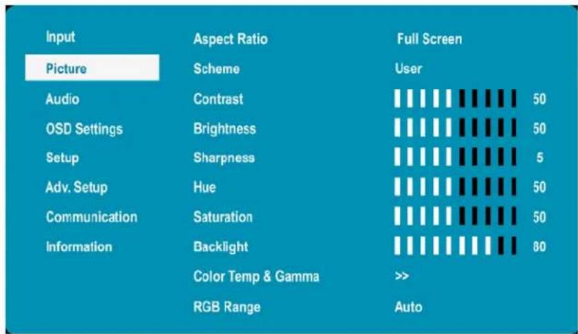
text_image
Input Picture Aspect Ratio Scheme Full Screen User Audio Contrast 50 OSD Settings Brightness 50 Setup Sharpness 5 Adv. Setup Hue 50 Communication Saturation 50 Information Backlight 80 Color Temp & Gamma >> RGB Range Auto| Aspect Ratio | |
| Adjust the aspect ratio of the screen. The first selection is for the main source, and the second selection is for sources 2-4.Options: Full Screen, Letterbox, 4:3, NativeDefault: Full Screen | |
| Scheme | |
| Press ▶ or ▶ to select one of the following:Options: User, Vivid, Cinema, Game, SportDefault: User | |
| Contrast | |
| Increase or decrease the contrast of picture. Press ▶ or ▶ to select the desired level.Range: 0~100Default: 50 | |
| Brightness | |
| Increase or decrease the brightness of picture. Press ▶ or ▶ to select the desired level.Range: 0~100Default: 50 | |
| Sharpness | |
| Adjust the definition of picture. Press ▶ or ▶ to select the desired level.Range: 0~10Default: 5 | |
Hue
Increase or decrease the green hue. Press ◀ or ▶ to select the desired level.
Range: 0\~100; Default: 50
Note: This function is not available when displaying PC or graphics sources
Saturation
Adjust the brilliance and brightness. Press ◀ or ▶ to select the desired level.
Range: 0\~100; Default: 50
Note: This function is not available when displaying PC or graphics sources
Backlight
Increase or decrease the intensity of the LCD backlight. Press ◀ or ▶ to select the desired level.
Range: 0\~100
Default: 80
Color Temp and Gamma
Select gamma
Options: Off, 1.85, 1.9, 1.95, 2.0, 2.05, 2.10, 2.15, 2.2, 2.25, 2.3, 2.35, 2.4, 2.45, 2.5, 2.55, 2.6
Default: 2.2
Select color temperature
Options: User, 3200K, 5000K, 6500K, 7500K, 9300K
Default: 9300K
RGB Range
Select RGB range for HDMI and DisplayPort sources
Options: Auto, Full, Limited
Default: Auto
Picture Menu – RGB Adjust Submenu
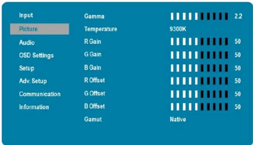
other
| Input | Gamma | 2.2 | |---|---|---| | Picture | Temperature | 9300K | | Audio | R Gain | 50 | | OSD Settings | G Gain | 50 | | Setup | B Gain | 50 | | Adv. Setup | R Offset | 50 | | Communication | G Offset | 50 | | Information | B Offset | 50 | | Gamut | Native | || Gamma | |
| Select gammaOptions: Off, 1.85, 1.9, 1.95, 2.0, 2.05, 2.10, 2.15, 2.2, 2.25, 2.3, 2.35, 2.4, 2.45, 2.5, 2.55, 2.6Default: 2.2 | |
| Temperature | |
| Select color temperatureOptions: User, 3200K, 5000K, 6500K, 7500K, 9300KDefault: 9300K | |
| R Gain | |
| Adjust the amount of red in bright contentRange: 0~100Default: 50 | |
| G Gain | |
| Adjust the amount of green in bright contentRange: 0~100Default: 50 | |
| B Gain | |
| Adjust the amount of blue in bright contentRange: 0~100Default: 50 | |
| R Offset | |
| Adjust the amount of red in dark contentRange: 0~100Default: 50 | |
G Offset
Adjust the amount of green in dark content
Range: 0\~100
Default: 50
B Offset
Adjust the amount of blue in dark content
Range: 0\~100
Default: 50
Gamut
Select the range of colors shown on the display
Options:
Native: Select the maximum range of colors
REC709: Select the color gamut used in HDTV content
SMPTE C: Select the color gamut used in SD content in the US
EBU: Select the color gamut used in SD content in Europe
Default: Native
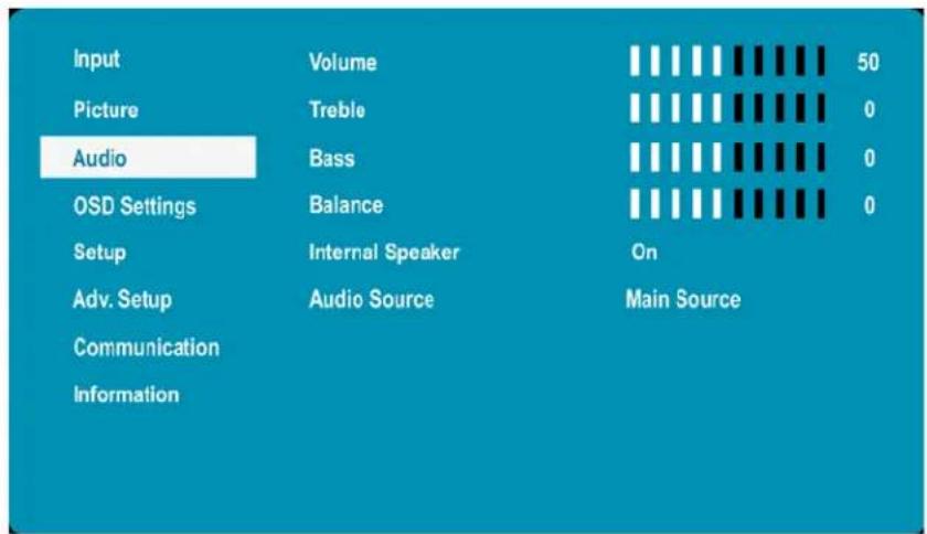
Audio Menu
This menu is used for adjusting audio settings.
text_image
Input Volume 50 Picture Treble 0 Audio Bass 0 OSD Settings Balance 0 Setup Internal Speaker On Adv. Setup Audio Source Main Source Communication InformationVolume
Adjust the sound. Press ◀ or ▶ to select the desired level.
Range: 0\~100
Default: 50
Treble
Adjust the sound in high tones (treble). Press ◀ or ▶ to select the desired level.
Range: -6\~+6
Default: 0
Bass
Adjust the sound in low tones (bass). Press ◀ or ▶ to select the desired level.
Range: -6\~+6
Default: 0
Balance
Adjust the balance of the left and right speakers. Press ◀ or ▶ to select the desired level.
Range: -6\~+6
Default: 0
Internal Speaker
Turn the internal speaker on or off
Default: On
Audio Source
Select the audio source that is played through the display's internal speakers, audio out and digital audio out.
Options: Audio In, Main Input, Source 2, Source 3, Source 4
Default: Main Source
Note: Settings for Source 2, Source 3 and Source 4 will only be enabled when Multi-Source Views mode is set to On.
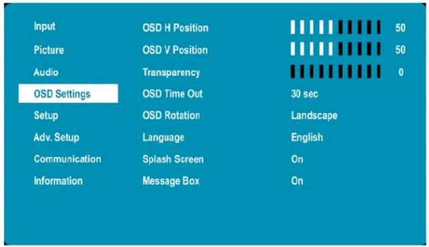
OSD Settings Menu
This menu is used to make initial setup adjustments to the OSD (On-Screen Display) menu and other on-screen messages.
text_image
Input OSD H Position 50 Picture OSD V Position 50 Audio Transparency 0 OSD Settings OSD Time Out 30 sec Setup OSD Rotation Landscape Adv. Setup Language English Communication Splash Screen On Information Message Box On| OSD H Position | |
| Adjust the horizontal position of the OSD menu. Press ◀ or ▶ to select the desired level.Range: 0~100Default: 50 | |
| OSD V Position | |
| Adjust the vertical position of the OSD menu. Press ◀ or ▶ to select the desired level.Range: 0~100Default: 50 | |
| Transparency | |
| Submenu to adjust the transparency of the OSD menu. Press ◀ or ▶ to select the desired level.Options: 0~10Default: 0 | |
| OSD Time Out | |
| Submenu to adjust the time in seconds before the OSD menu disappears. Press ◀ or ▶ to select the desired level.Options: 5 sec, 10 sec, 20 sec, 30 sec, 60 secDefault: 30 sec | |
| OSD Rotation | |
| Select the OSD Rotation. Press ◀ to select the rotation.Options: Landscape, PortraitDefault: Landscape | |
Language
Select the OSD language
Options: English, French, German, Italian, Portuguese, Spanish, Chinese (Traditional), Chinese (Simplified), Japanese
Default: English
Splash Screen
Select whether a splash screen appears when the monitor is powered up
Options: On, Off
Default: On
Message Box
Select whether a message box is displayed on screen
Options: On, Off
Default: On
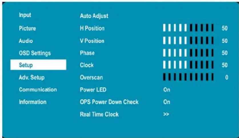
Setup Menu
text_image
Input Picture Audio OSD Settings Setup Adv. Setup Communication Information Auto Adjust H Position V Position Phase Clock Overscan Power LED OPS Power Down Check Real Time Clock On 50 50 50 50 0 On >>Auto Adjust
| Force the display to reacquire and lock to the input signal (VGA source only). This is useful when the signal quality is marginal. Note: This feature does not continually reacquire the signal.Options: No, YesDefault: No | |
| H Position | |
| Adjust the horizontal position of the image (VGA source only). Press ◀ or ▶ to select the desired level.Range: 0~100Default: 50 | |
| V Position | |
| Adjust the vertical position of the image (VGA source only). Press ◀ or ▶ to select the desired level.Range: 0~100Default: 50 | |
| Phase | |
| Adjust the phase of the displayed signal (VGA source only). Press ◀ or ▶ to select the desired level.Range: 0~100 | |
| Clock | |
| Adjust the clock of the displayed signal (VGA source only). Press ◀ or ▶ to select the desired level.Range: 0~100 |
Overscan
Adjust the zoom (overscan) of the image
Default: 0
Power LED
Enable or disable the status LED
Options: On, Off
Default: On
OPS Power Down Check
Allow the display to skip waiting for the OPS module to power down when the display is powering down
Default: On
Real Time Clock
See details on next page
Real Time Clock Submenu
This menu is used to set the internal clock of the display, and to power on and power off the display at preset times if desired.
| Current Time | 2017 / 12 / 05 | 14 : 40 | Tuesday | |
| Timer Mode | User Mode | |||
| Weekday | Enable | Power On | PowerOff | |
| Monday | □ | 00 : 00 | 00 : 00 | |
| Tuesday | □ | 00 : 00 | 00 : 00 | |
| Wednesday | □ | 00 : 00 | 00 : 00 | |
| Thursday | □ | 00 : 00 | 00 : 00 | |
| Friday | □ | 00 : 00 | 00 : 00 | |
| Saturday | □ | 00 : 00 | 00 : 00 | |
| Sunday | □ | 00 : 00 | 00 : 00 | |
Current Time
Set the year, month, day, and time of day
Options: User Mode, Workday Mode, Everyday Mode
Real Time Clock – User Mode
| Current Time | 2017 / 12 / 05 | 14 : 40 | Tuesday | |
| Timer Mode | User Mode | |||
| Weekday | Enable | Power On | Power Off | |
| Monday | □ | 00 : 00 | 00 : 00 | |
| Tuesday | □ | 00 : 00 | 00 : 00 | |
| Wednesday | □ | 00 : 00 | 00 : 00 | |
| Thursday | □ | 00 : 00 | 00 : 00 | |
| Friday | □ | 00 : 00 | 00 : 00 | |
| Saturday | □ | 00 : 00 | 00 : 00 | |
| Sunday | □ | 00 : 00 | 00 : 00 | |
User Mode
Select the power on/off time for each day of the week
Options: Disable, Enable
Use the arrow keys to specify the on and off times.
Real Time Clock – Workday Mode
| Current Time | 2017 / 12 / 05 | 14 : 40 | Tuesday | |
| Timer Mode | Workdays | |||
| Weekday | Enable | Power On | Power Off | |
| Monday ~ Friday | 00 : 00 | 00 : 00 | ||
| Saturday | 00 : 00 | 00 : 00 | ||
| Sunday | 00 : 00 | 00 : 00 | ||
Workday Mode
Select the power on/off time for Monday–Friday, Saturday, and Sunday
Options: Disable, Enable
Use the arrow keys to specify the on and off times.
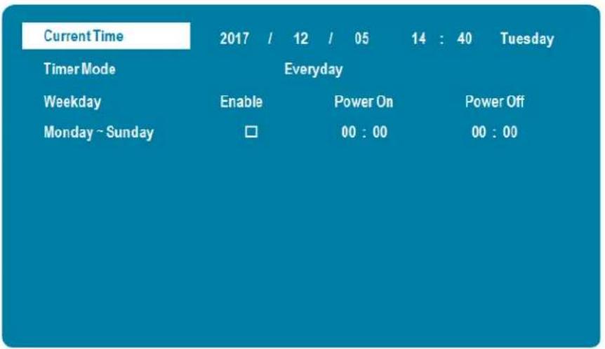
Real Time Clock – Everyday Mode
text_image
Current Time 2017 / 12 / 05 14 : 40 Tuesday Timer Mode Everyday Weekday Enable Power On Power Off Monday ~ Sunday □ 00 : 00 00 : 00Everyday Mode
Select the power on/off time for all days of the week
Options: Disable, Enable
Use the arrow keys to specify the on and off times.
Advanced Setup Menu
| Input | Smart Light Control | Off |
| Picture | Pixel Orbit | Off |
| Audio | Power Saving Config | Wake On VGA |
| OSD Settings | DP1 Ver. | 1.2 |
| Setup | DP2 Ver. | 1.2 |
| Adv. Setup | EDID Setup | >> |
| Communication | Touch Control | Auto |
| Information | Factory Reset | >> |
Smart Light Control
Enable dynamic contrast (DCR) or ambient light sensor
Options: Off, DCR, Light Sensor
Default: Off
Pixel Orbit
Create slight frame motion to help avoid image retention
Options: On, Off
Default: Off
Power Saving Config
Options: Wake on VGA, Wake on All, Always On
Default: Wake on VGA
Note: For Wake on VGA and Wake on All, the display will enter power saving mode if no signal is received for 5 minutes.
DP1 Ver.
Select the DisplayPort version of the DP1 input
Options: 1.1, 1.2
Default: 1.2
Note: DisplayPort 1.2 is the more modern standard and supports 3840x2160 @ 60 Hz resolution. However, sometimes DisplayPort 1.1 is needed for compatibility with older graphics cards.
DP2 Ver.
Select the DisplayPort version of the DP2 input
Options: 1.1, 1.2
Default: 1.2
Note: DisplayPort 1.2 is the more modern standard and supports 3840x2160 @ 60 Hz resolution. However, sometimes DisplayPort 1.1 is needed for compatibility with older graphics cards.
EDID Setup
Select EDID (Extended Display Identification Data) of the HDMI and DisplayPort inputs
Options:
HDMI 1, HDMI2: 1080p, 4K2K 30Hz;
DP1, DP2, HDMI 3, HDMI 4 and OPS: 1080p, 4K2K 30Hz, 4K2K 60Hz.
Default:
HDMI 1, HDMI2: 4K2K 30Hz;
Other inputs: 4K2K 60Hz.
Note: Use the 1080p setting for the broadest support of lower resolution sources. Use the 4K2K setting to support high resolution sources such as 3840x2160.
Touch Control
Select whether the touchscreen controls the internal OPS PC, or controls an external PC via the Touch USB connector
Options: Auto, OPS, External
Default: Auto
Factory Reset
Restore all settings to their default
Options: No, Yes
Default: No
Communication Menu
This menu configures the display's RS-232 and Ethernet communication ports.
| Input | Baud Rate | 19200 |
| Picture | Enable Network | Off |
| Audio | IP Address Settings | >> |
| OSD Settings | Power Status Alert | Off |
| Setup | Source Status Alert | Off |
| Adv. Setup | Signal Lost Alert | Off |
| Communication | Load Default | >> |
| Information | SNMP | >> |
| IP Address | 192.168. 2. 1 | |
| Device MAC | 00:00:00:00:00:00 |
Baudrate
Select the baud rate of the display's RS-232 port
Options: 115200, 38400, 19200, 9600
Default: 19200
Enable Network
Enable the display's built-in Ethernet port
Options: On, Off
Default: Off
IP Address Settings
Enable Dynamic IP mode or set the static IP address of the display's Ethernet port
Power Status Alert
Enable an automatic alert when the display is powered down
Options: On, Off
Default: Off
Source Status Alert
Enable an automatic alert when the source is changed
Options: On, Off
Default: Off
Signal Lost Alert
Enable an automatic alert when the video signal is lost
Options: On, Off
Default: Off
Load Default
Load default communication settings
Options: No, Yes
Default: No
SNMP
Configure the Simple Network Management Protocol (SNMP) settings
IP Address
Show the IP address of the display
Device MAC
Show the MAC address of the display
Assigning an IP Address to the Display
To assign an IP address to your display, access the IP Address Settings Menu in the Communication menu. Consult your system administrator if you do not know how to configure the parameters shown in the menu.
| Dynamic IP | Disable | |||
| Static IP Address | 192 . | 168 . | 2 . | 1 |
| Subnet Mask | 255 . | 255 . | 255 . | 0 |
| Gateway | 192 . | 168 . | 2 . | 1 |
| DNS Addr. | 192 . | 168 . | 2 . | 1 |
| Save Settings | No | |||
| Refresh | >>> | |||
The default settings are shown below.
| Item Setting | |
| Dynamic IP Disable | |
| Static IP Address 192.168.2.1 | |
| Subnet Mask 255.255.255.0 | |
| Gateway 192.168.2.1 | |
| DNS Addr. 192.168.2.1 |
Information Menu
This read-only menu provides information on the active sources and the latest firmware version.
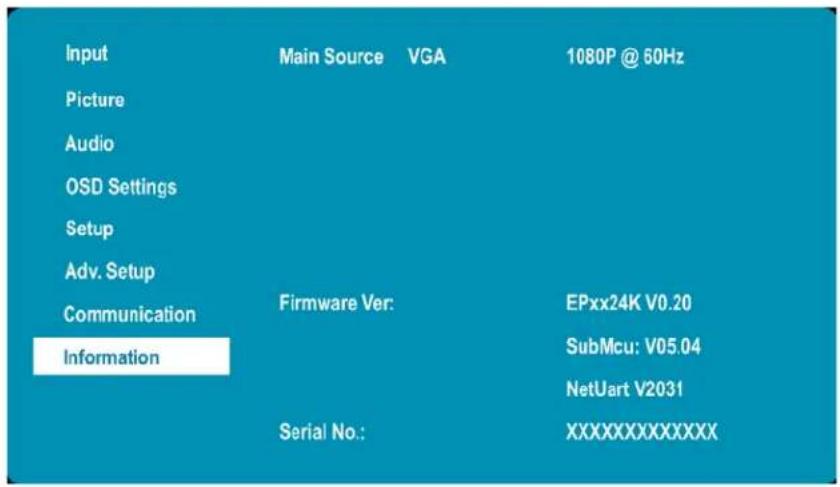
text_image
Input Picture Audio OSD Settings Setup Adv. Setup Communication Information Main Source VGA 1080P @ 60Hz Firmware Ver: EPxx24K V0.20 SubMcu: V05.04 NetUart V2031 Serial No.: XXXXXXXXXXXXXUsing the Touch Screen
You can use the touch screen to control your Windows, Mac or Linux operating system. The Planar PS Series is HID compliant, delivering up to 20 points of touch on both Windows and Linux without a driver. Single touch only is supported for Mac operating systems. To achieve more than single touch Mac support, drivers will need to be installed, which can be found on http://www.planar.com/support.
Note: Ensure that you have installed the USB cable on the display to a computer.
Note: If an OPS PC is installed in the OPS slot, the OPS PC will automatically be connected internally to the touch system. The touch functionality is configurable via the Touch Control settings.
LAN Control
The Planar EP Series supports extending access to the RS232 commands over a network connection using a virtual COM port (VCOM). The VCOM driver can be found on http://www.planar.com/support.
Note: RS232 commands over LAN can be achieved by opening a TCP connection to Port 23 to the display. The LAN control functionality is most frequently used by control systems, and they won't be able to use the VCOM drivers
Supported Operating Systems
The utility supports the following operating systems:
- Windows 7
- Windows 8 and 8.1
- Windows 10
Installation
Use the following instructions to install the VCOM driver.
1 Launch the vcomsetup.exe file.
2 You may see a security warning similar to the following example. Click Run to continue.
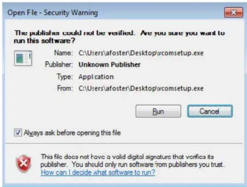
text_image
Open File - Security Warning The publisher could not be verified. Are you sure you want to run this software? Name: C:\Users\afoster\Desktop\vcomsetup.exe Publisher: Unknown Publisher Type: Application From: C:\Users\afoster\Desktop\vcomsetup.exe Run Cancel Always ask before opening this file This file does not have a valid digital signature that verifies it a publisher. You should only run software from publishers you trust. How can I decide what software to run?3 The vcomsetup.exe installer installs both the VCOM virtual serial port and also a utility (WinPcap) for finding your displays on the network. Follow the steps in the two installers, accepting defaults and license agreements as needed.
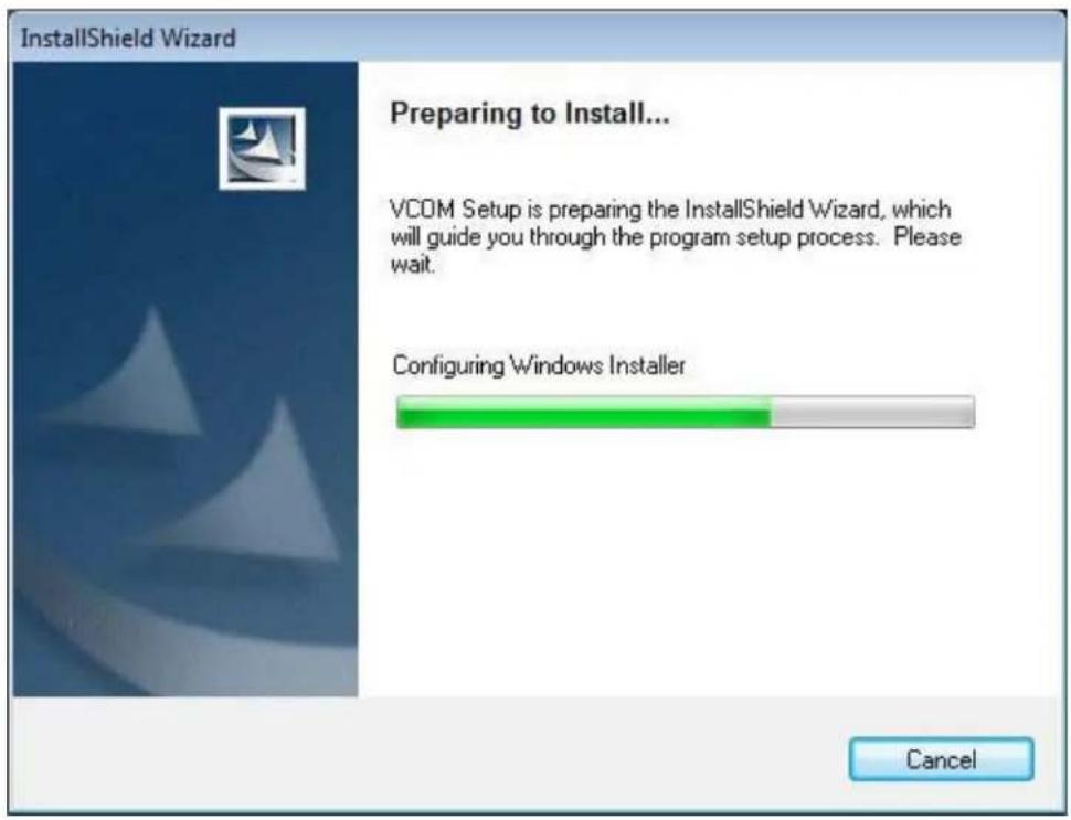
text_image
InstallShield Wizard Preparing to Install... VCOM Setup is preparing the InstallShield Wizard, which will guide you through the program setup process. Please wait. Configuring Windows Installer Cancel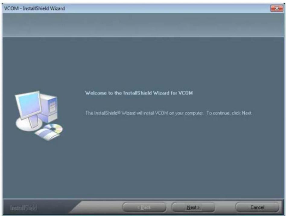
text_image
VCOM - InstallShield Wizard Welcome to the InstallShield Wizard for VCOM The InstallShield® Wizard will install VCOM on your computer. To continue, click Next. InstallShield < Back Next > Cancel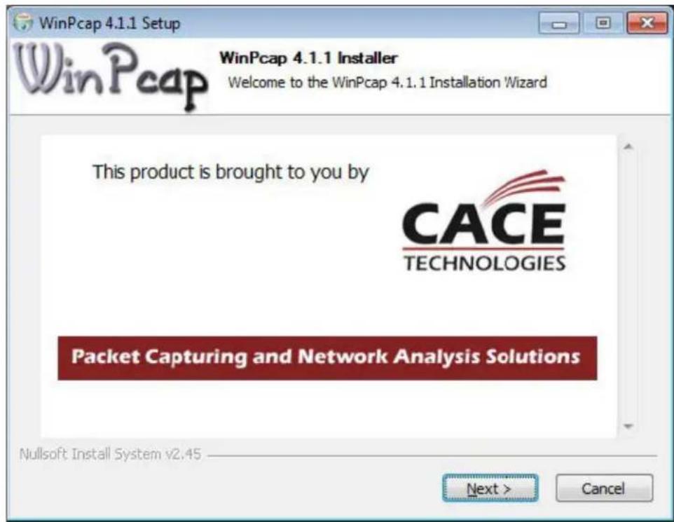
text_image
WinPcap 4.1.1 Setup WinPcap 4.1.1 Installer Welcome to the WinPcap 4.1.1 Installation Wizard This product is brought to you by CACE TECHNOLOGIES Packet Capturing and Network Analysis Solutions Nullsoft Install System v2.45 Next > Cancel4 When the installers are finished, you will see a VCOM icon on your desktop and you find two new folders in your start menu: IC Plus corp (with VCOM sub folder) and WinPcap. If you need to uninstall the software, there are shortcuts to uninstall from these menus.

Configuring VCOM
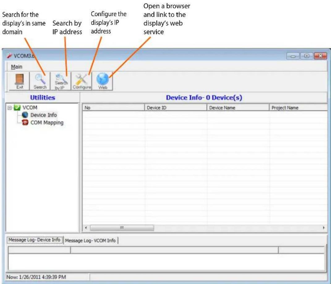
Use the VCOM shortcut to launch the VCOM setup utility. The utility starts up on the Device Info page, shown below. The controls on this page allow you to find and configure each display that you want to access via virtual COM ports.
text_image
Search for the display's in same domain Search by IP address Configure the display's IP address Open a browser and link to the display's web service Main Exit Search Search by IP Configure Web Utilities Device Info- 0 Device(s) VCOM Device Info COM Mapping No Device ID Device Name Project Name Message Log- Device Info Message Log- VCOM Info Now: 1/26/2011 4:39:39 PMClick on COM Mapping to display the COM Mapping page, shown below. The controls on this page allow you to make virtual COM ports and select the display to which you want to map each virtual COM port.
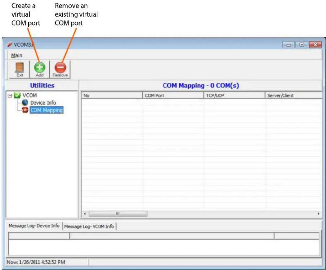
text_image
Create a virtual COM port Remove an existing virtual COM port VCOM3.0 Main Exit Add Remove Utilities COM Mapping - 0 COM(s) VCOM Device Info COM Mapping No COM Port TCP/UDP Server/Client Message Log- Device Info | Message Log- VCOM Info | Now: 1/26/2011 4:52:52 PMFunction Descriptions
Search
In the Device Info page, click the Search icon. This function searches for any devices that are connected to the same network segment (maximum of 254 devices) as your PC. Any devices found will be listed in the Device Info table.
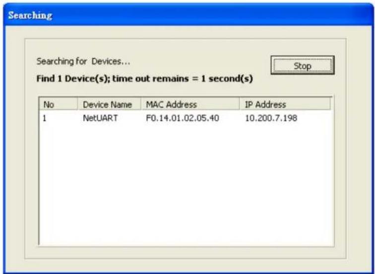
text_image
Searching Searching for Devices... Find 1 Device(s); time out remains = 1 second(s) No Device Name MAC Address IP Address 1 NetUART F0.14.01.02.05.40 10.200.7.198Search By IP
On the Device Info page, click the Search by IP icon. This function searches for any devices in the given IP address range. Any devices found will be listed in the Device Info table.
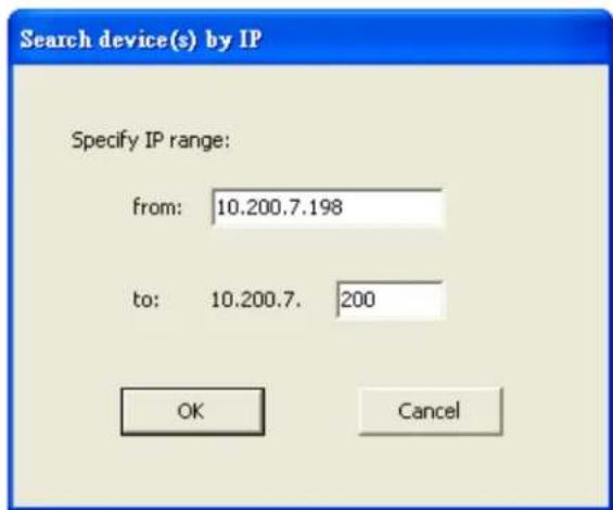
text_image
Search device(s) by IP Specify IP range: from: 10.200.7.198 to: 10.200.7. 200 OK CancelConfigure IP Address
This function allows you to configure the network settings of the selected device. We recommend using the on-screen menus or the web interface described in the User Guide instead of this function.
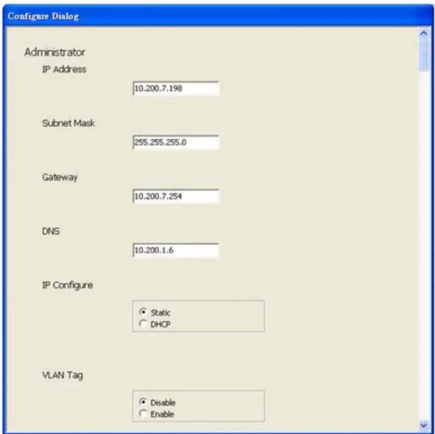
text_image
Configure Dialog Administrator IP Address 10.200.7.198 Subnet Mask 255.255.255.0 Gateway 10.200.7.254 DNS 10.200.1.6 IP Configure Static DHCP VLAN Tag Disable EnableNote: To cancel this function, scroll to the bottom and click the Cancel button.
Web
Click the Web icon to launch your default browser and link it to the display's web service.
Adding a Virtual COM Port
To add a virtual COM port, click the Add icon on the COM Mapping page to open the following dialog window.
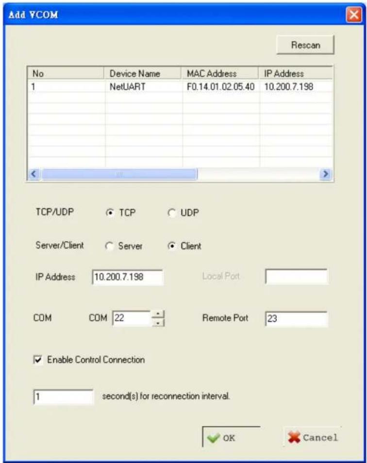
text_image
Add YCOM Rescan No Device Name MAC Address IP Address 1 NetUART F0.14.01.02.05.40 10.200.7.198 TCP/UDP TCP UDP Server/Client Server Client IP Address 10.200.7.198 Local Port COM COM 22 Remote Port 23 Enable Control Connection 1 second(s) for reconnection interval. OK CancelSelect the display you want to control from the table and accept defaults, as shown. Make a note of the COM number assigned to the new VCOM port. Click OK to create the new port. The new port appears in the COM Mapping table.
You can view details for the virtual COM port device using Device Manager, shown below.
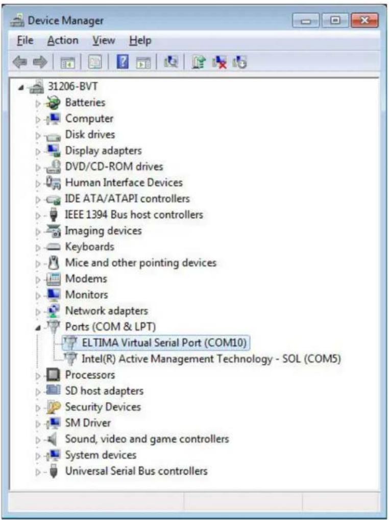
text_image
Device Manager File Action View Help 31206-BVT Batteries Computer Disk drives Display adapters DVD/CD-ROM drives Human Interface Devices IDE ATA/ATAPI controllers IEEE 1394 Bus host controllers Imaging devices Keyboards Mice and other pointing devices Modems Monitors Network adapters Ports (COM & LPT) ELTIMA Virtual Serial Port (COM10) Intel(R) Active Management Technology - SOL (COM5) Processors SD host adapters Security Devices SM Driver Sound, video and game controllers System devices Universal Serial Bus controllersRemoving a COM Port
On the COM Mapping page, select the COM port you want to delete and click the REMOVE button.
Setting Up Email Alerts
The web service allows you to configure the settings required to send email alerts. If you are not using email alerts, you do not need to use the web service and can skip this section.
Login
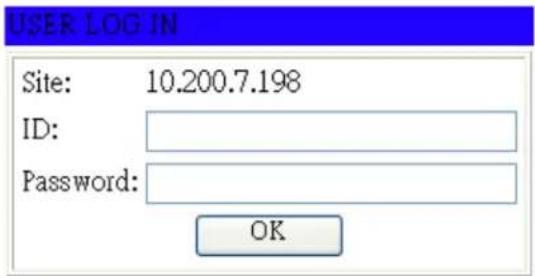
When you direct your browser to the network IP address of the display, you are prompted to login as shown here.
text_image
USER LOG IN Site: 10.200.7.198 ID: Password: OKThe default ID is admin and the default password is system.
Note: Cookies and JavaScript must be enabled in your browser.
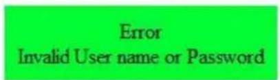
Note: If your session times out or if you enter an incorrect ID or password, you will see the following message.
text_image
Error Invalid User name or Password
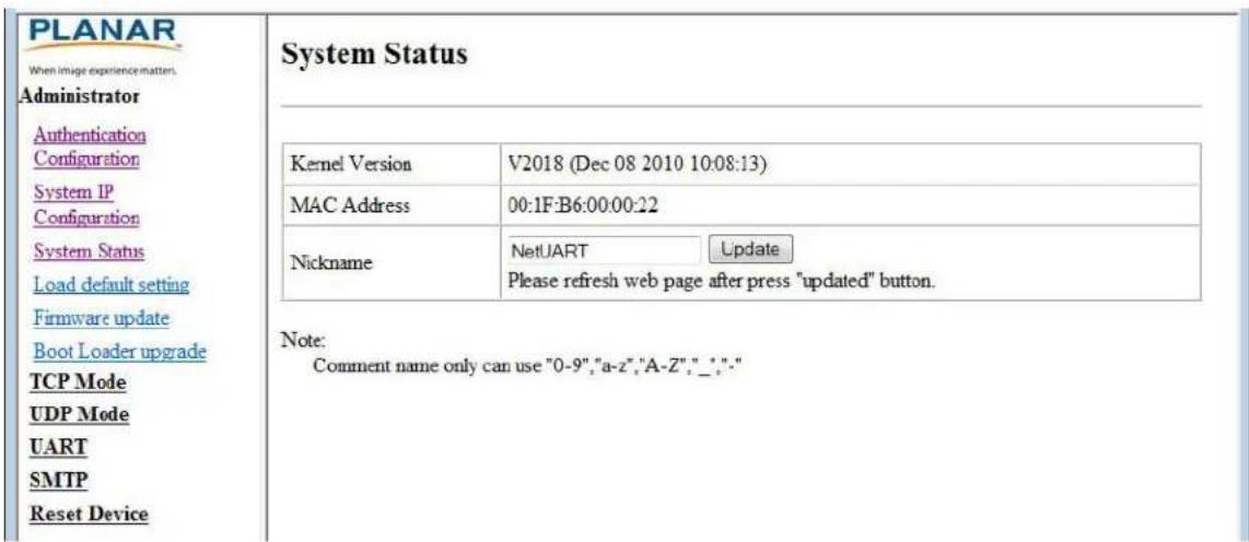
When you first login, you will see the System Status page, as shown here.
PLANAR
When image experience matters.
Administrator
TCP Mode
UDP Mode
UART
SMTP
Reset Device
System Status
| Kernel Version | V2018 (Dec 08 2010 10:08:13) | |
| MAC Address | 00.1F.B6.00.00.22 | |
| Nickname | NetUARTUpdatePlease refresh web page after press "updated" button. | |
Note:
Comment name only can use "0-9', 'a-z', 'A-Z', "_', "-"
Administrator
Click on the word Administrator under the Planar logo to show/hide these menu items.
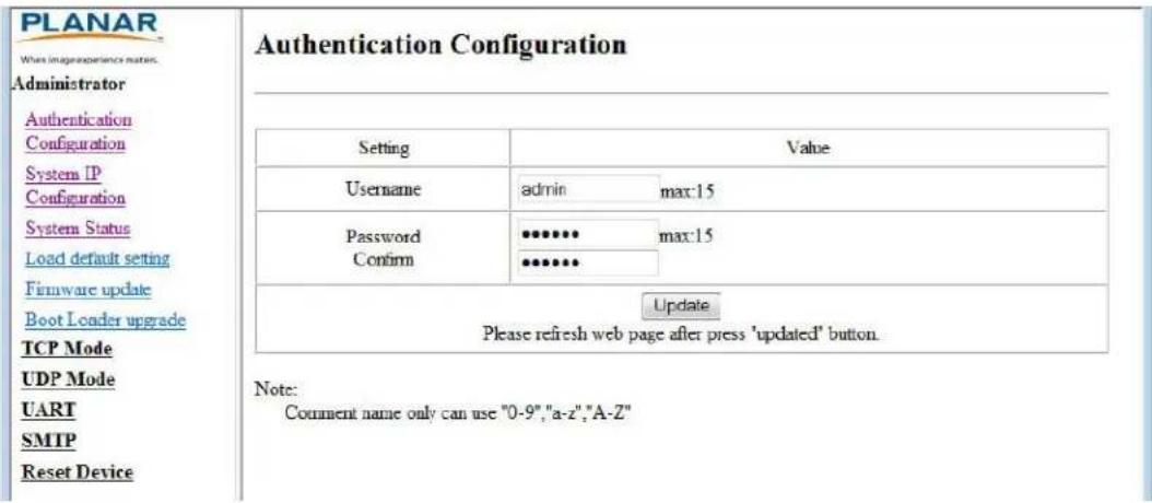
Authentication Configuration
Set user ID and password for login to the web service.
text_image
PLANAR When image experience matrix. Administrator Authentication Configuration System IP Configuration System Status Load default setting Firmware update Boot Loader upgrade TCP Mode UDP Mode UART SMTP Reset Device Authentication Configuration Setting Value Username admin[max:15] Password ******** max:15 Confirm ******** Update Please refresh web page after press 'updated' button. Note: Comment name only can use "0-9","a-z","A-Z"System IP Configuration
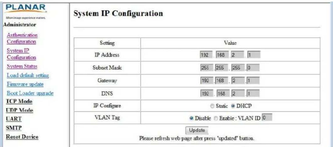
You can view and/or change the network settings here. However, for best results, we recommend that you use the on-screen display menus.
text_image
PLANAR Registration experience notes. Administrator Authentication Configuration System IP Configuration System Status Load default setting Firmware update Boot Loader upgrade TCP Mode UDP Mode UART SMTP Reset DeviceIf your network requires a VLAN tag, your network administrator will give you a number from 1 to 4094 to enter here.
System Status
- Kernel version - Shows the firmware version for the network interface.
- MAC Address - Shows the unique address assigned to the network interface.
- Nickname - Enter a device tag, up to 12 characters. This tag will appear in email alerts, which help you identify the source of the alert.
text_image
PLANAR When image experience matters. Administrator Authentication Configuration System IP Configuration System Status Load default setting Firmware update Boot Loader upgrade TCP Mode UDP Mode UART SMTP Reset Device System Status Kernel Version V2018 (Dec 08 2010 10:08:13) MAC Address 00:1F:B6:00:00:22 Nickname NetUART Update Please refresh web page after press "updated" button. Note: Comment name only can use "0-9","a-z","A-Z","_";:"Load Default Setting
1 Click the LOAD button to return the network interface to default settings.
Load Default Setting to EEPROM
Load
2 After a few seconds, you will see a green box with the message "Setting Saved RESET." Click the RESET button to restart the network interface.
Setting Saved RESET
Reset
3 Make sure the IP address in your browser is correct and then click OK.
Type IP in URL
ok
4 When the process is complete, you should see the login page again.
Firmware Update and Boot Loader Upgrade
In most cases, you will not need to update firmware for the network interface. If you do, contact Planar's Technical Support Department. See "Accessing Planar's Technical Support Website" on page 78 for more information.
WARNING! Do not use the controls in these two sections unless you have received a specific procedure and firmware from Planar. Following improper procedures can disable the network interface and require factory repair service.
TCP Mode, UDP Mode and UART
For normal operation, you will not need to change any settings on these pages. If you do need to change information, Planar's Technical Support Department will provide you with more information.
SMTP
| Enable SMTP | □ Enable,Port: 25 |
| SMTP server address | smtp.xxx.yyy |
| SMTP Login Information | □ Enable Username: username,Password: ******** |
| Mail to | xxx@yyy.zzz max: 200 |
| Mail from | xxx@yyy.zzz |
Your network administrator must provide information for the following fields:
- Enable SMTP - Make sure this checkbox is checked. Port 25 is the default.
- SMTP Server Address - Name or IP address of the mail server.
- SMTP Login Information - If required, check the ENABLE box and enter a username and password.
- Mail to - Enter the destination email addresses. Separate multiple addresses with a semi-colon.
Mail from - Enter the email address from which you want to send alerts.
| SMTP 01 Warning | |
| Subject | Power Status Change Alert |
| Message Body | SMTP 01 bcdymax: 100 |
| SMTP 02 Warning | |
| Subject | Source Change Alert |
| Message Body | SMTP 02 bcdymax: 100 |
| SMTP 03 Warning | |
| Subject | Signal Lost Alert |
| Message Body | SMTP 03 bcdymax: 100 |
You can edit the subject and body of the email warnings, which are sent when there is a power status change, source change and signal lost. The SMTP 04 and 05 warnings are not used.
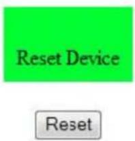
Reset Device
Click the RESET button to reboot the network interface. Note that the current settings are not changed.
text_image
Reset Device ResetSignal Compatibility
| Signal Type | Resolution | Frame rate (Hz) | Line Rate (kHz) | Pixel Rate (MHz) | HDMI 3-4 & OPS | HDMI 1-2 | DP1-2 | VGA | References | |||||||
| P | C | 6 | 4 | 0 | x | 4 | 8 | 0 | 5 | 9 | . | 9 | 4 | 0 | 3 | 1 |
| 6 | 4 | 0 | x | 4 | 8 | 0 | 7 | 2 | . | 8 | 0 | 9 | 3 | 7 | ||
| 6 | 4 | 0 | x | 4 | 8 | 0 | 7 | 5 | . | 0 | 0 | 0 | 3 | 7 | ||
| 6 | 4 | 0 | x | 4 | 8 | 0 | 8 | 5 | . | 0 | 0 | 8 | 4 | 3 | ||
| 8 | 0 | 0 | x | 6 | 0 | 0 | 6 | 0 | . | 3 | 1 | 7 | 3 | 7 | ||
| 8 | 0 | 0 | x | 6 | 0 | 0 | 7 | 2 | . | 1 | 8 | 8 | 4 | 8 | ||
| 8 | 0 | 0 | x | 6 | 0 | 0 | 7 | 5 | . | 0 | 0 | 0 | 4 | 6 | ||
| 8 | 0 | 0 | x | 6 | 0 | 0 | 8 | 5 | . | 0 | 6 | 1 | 5 | 3 | ||
| 8 | 4 | 8 | x | 4 | 8 | 0 | 5 | 9 | . | 6 | 5 | 9 | 2 | 9 | ||
| 8 | 4 | 8 | x | 4 | 8 | 0 | 7 | 4 | . | 7 | 6 | 9 | 3 | 7 | ||
| 8 | 4 | 8 | x | 4 | 8 | 0 | 8 | 4 | . | 7 | 5 | 1 | 4 | 2 | ||
| 1 | 0 | 2 | 4 | x | 7 | 6 | 8 | 6 | 0 | . | 0 | 0 | 4 | 4 | ||
| 1 | 0 | 2 | 4 | x | 7 | 6 | 8 | 7 | 0 | . | 0 | 6 | 9 | 5 | ||
| 1 | 0 | 2 | 4 | x | 7 | 6 | 8 | 7 | 5 | . | 0 | 2 | 9 | 6 | ||
| 1 | 0 | 2 | 4 | x | 7 | 6 | 8 | 8 | 4 | . | 9 | 9 | 7 | 6 | ||
| 1 | 1 | 5 | 2 | x | 8 | 6 | 4 | 7 | 0 | . | 0 | 1 | 2 | 6 | ||
| 1 | 1 | 5 | 2 | x | 8 | 6 | 4 | 7 | 5 | . | 0 | 0 | 0 | 6 | ||
| 1 | 1 | 5 | 2 | x | 8 | 6 | 4 | 8 | 4 | . | 9 | 9 | 9 | 7 | ||
| 1 | 2 | 8 | 0 | x | 7 | 6 | 8 | 4 | 9 | . | 9 | 2 | 9 | 3 | ||
| 1 | 2 | 8 | 0 | x | 7 | 6 | 8 | 5 | 9 | . | 9 | 9 | 5 | 4 | ||
| 1 | 2 | 8 | 0 | x | 7 | 6 | 8 | 5 | 9 | . | 8 | 7 | 0 | 4 | ||
| 1 | 2 | 8 | 0 | x | 7 | 6 | 8 | 7 | 4 | . | 8 | 9 | 3 | 6 | ||
| 1 | 2 | 8 | 0 | x | 7 | 6 | 8 | 8 | 4 | . | 8 | 3 | 7 | 6 | ||
| 1 | 2 | 8 | 0 | x | 9 | 6 | 0 | 6 | 0 | . | 0 | 0 | 0 | 6 | ||
| 1 | 2 | 8 | 0 | x | 9 | 6 | 0 | 7 | 5 | . | 0 | 0 | 0 | 7 | ||
| 1 | 2 | 8 | 0 | x | 9 | 6 | 0 | 8 | 5 | . | 0 | 0 | 2 | 8 | ||
| 1 | 2 | 8 | 0 | x | 1 | 0 | 2 | 4 | 6 | 0 | . | 0 | 2 | 0 | ||
| 1 | 2 | 8 | 0 | x | 1 | 0 | 2 | 4 | 7 | 5 | . | 0 | 2 | 5 | ||
| 1 | 2 | 8 | 0 | x | 1 | 0 | 2 | 4 | 8 | 5 | . | 0 | 2 | 4 | ||
| 1 | 3 | 6 | 6 | x | 7 | 6 | 8 | 5 | 9 | . | 7 | 9 | 0 | 4 | ||
| Signal Type | Resolution | Frame rate (Hz) | Line Rate (kHz) | Pixel Rate (MHz) | HDMI 3-4 & OPS | HDMI 1-2 | DP1-2 | VGA | References | ||||||
| P | C | 1 | 4 | 0 | 0 | x | 1 | 0 | 5 | 0 | 4 | 9 | 9 | 6 | 5 |
| 1 | 4 | 0 | 0 | x | 1 | 0 | 5 | 0 | 5 | 9 | 9 | 4 | 8 | ||
| 1 | 4 | 0 | 0 | x | 1 | 0 | 5 | 0 | 5 | 9 | 9 | 7 | 8 | ||
| 1 | 4 | 0 | 0 | x | 1 | 0 | 5 | 0 | 7 | 4 | 8 | 6 | 7 | ||
| 1 | 6 | 0 | 0 | x | 1 | 2 | 0 | 0 | 6 | 0 | 0 | 0 | 0 | ||
| 1 | 9 | 2 | 0 | x | 1 | 0 | 8 | 0 | 4 | 9 | 9 | 2 | 9 | ||
| 1 | 9 | 2 | 0 | x | 1 | 0 | 8 | 0 | 5 | 9 | 9 | 6 | 3 | ||
| 1 | 9 | 2 | 0 | x | 1 | 0 | 8 | 0 | 5 | 9 | 9 | 5 | 0 | ||
| 1 | 9 | 2 | 0 | x | 1 | 2 | 0 | 0 | 4 | 9 | 9 | 3 | 2 | ||
| 1 | 9 | 2 | 0 | x | 1 | 2 | 0 | 0 | 5 | 9 | 9 | 5 | 0 | ||
| 1 | 6 | 8 | 0 | x | 1 | 0 | 5 | 0 | 4 | 9 | 9 | 7 | 4 | ||
| 1 | 6 | 8 | 0 | x | 1 | 0 | 5 | 0 | 5 | 9 | 9 | 5 | 4 | ||
| 1920x2160 | 60.000 | 135.000 | 297.000 | x | x | x | CEA-861-F, VIC 16, with vertical parameters doubled | ||||||||
| 1920x2160 59 | .988 133.2 | 93 277.250 | xxx VESA | CVT-R | |||||||||||
| 2560x1440 59 | .951 88.78 | 7 241.500 | xxx VESA | CVT-R | |||||||||||
| 2560x1600 59 | .972 98.71 | 3 268.500 | xxx VESA | CVT-R | |||||||||||
| 3840x2160 23 | .999 52.43 | 8 209.750 | xxx VESA | CVT-R | |||||||||||
| 3840x2160 29 | .981 65.68 | 8 262.750 | xxx VESA | CVT-R | |||||||||||
| 3840x2160 49 | .977 110.5 | 00 442.000 | x | x VESA CVT-R | |||||||||||
| 3840x2160 59 | .997 133.3 | 13 533.250 | x | x VESA CVT-R | |||||||||||
| Apple Mac | 640x480 | 66.59 | xxxx | ||||||||||||
| 832x624 | 75.087 49 | .107 55.00 | 0xxxx | ||||||||||||
| 1024x768 | 59.278 48 | .193 64.00 | xxxx | ||||||||||||
| 1024x768 | 74.927 60 | .241 80.00 | xxxx | ||||||||||||
| 1152x870 | 75.062 68 | .681 100.00 | 0xxxx | ||||||||||||
| SDTV | 480i | 60 | x | x | SMPTE 125M, CEA-861-F Formats 6 &7 | ||||||||||
| 576i | 50 | xx | ITU-R | BT.601, CEA-861-F Formats 21 & 22 | |||||||||||
| EDTV | 480p | 60 | 31.469 | 27.000 | x | x | x | x | ITU-R BT.1358, CEA-861-F Format 17 & 18 | ||||||
| 576p | 50 | 31.250 | 27.000 | x | x | x | x | SMPTE 125M, CEA-861-F Format 6 & 7 | |||||||
| Signal Type | Resolution | Frame rate (Hz) | Line Rate (kHz) | Pixel Rate (MHz) | HDMI 3-4 & OPS | HDMI 1-2 | DP1-2 | VGA | References | |||||||
| H | D | T | V | 1 | 0 | 8 | 0 | i | 5 | 0 | 2 | 8 | . | 1 | 2 | 5 |
| 1 | 0 | 8 | 0 | i | 6 | 0 | 3 | 3 | . | 7 | 5 | 0 | 7 | 4 | . | |
| 7 | 2 | 0 | p | 5 | 0 | 3 | 7 | . | 5 | 0 | 0 | 7 | 4 | . | 2 | |
| 7 | 2 | 0 | p | 6 | 0 | 4 | 5 | . | 0 | 0 | 0 | 7 | 4 | . | 2 | |
| 1 | 0 | 8 | 0 | p | 2 | 4 | 2 | 7 | . | 0 | 0 | 0 | 7 | 4 | ||
| 1 | 0 | 8 | 0 | p | 2 | 5 | 2 | 8 | . | 1 | 2 | 5 | 7 | 4 | ||
| 1 | 0 | 8 | 0 | p | 3 | 0 | 3 | 3 | . | 7 | 5 | 0 | 7 | 4 | ||
| 1 | 0 | 8 | 0 | p | 5 | 0 | 5 | 6 | . | 2 | 5 | 0 | 1 | 4 | ||
| 1 | 0 | 8 | 0 | p | 6 | 0 | 6 | 7 | . | 5 | 0 | 0 | 1 | 4 | ||
| UHDTV | 3840x2160 | 24 | 54.000 | 297.000 | x | x | x | CEA-861-F Format 93, HDMI 1.4b VIC 1 | ||||||||
| 3840x2160 | 25 | 56.250 | 297.000 | x | x | x | CEA-861-F Format 94, HDMI 1.4b VIC 2 | |||||||||
| 3840x2160 | 30 | 67.500 | 297.000 | x | x | x | CEA-861-F Format 95, HDMI 1.4b VIC 3 | |||||||||
| 3840x2160 | 50 | 56.250 | 297.000 | x | CEA-861-F Format 96, 4:2:0 sub-sampling | |||||||||||
| 3840x2160 | 50 | 112.500 | 594.000 | x | x | CEA-861-F Format 96 | ||||||||||
| 3840x2160 | 60 | 67.500 | 297.000 | x | CEA-861-F Format 97, 4:2:0 sub-sampling | |||||||||||
| 3840x2160 | 60 | 135.000 | 594.000 | x | x | CEA-861-F Format 97 | ||||||||||
| 4096x2160 | 24 | 54.000 | 297.000 | x | x | x | CEA-861-F Format 98 | |||||||||
| 4096x2160 | 25 | 56.250 | 297.000 | x | x | x | CEA-861-F Format 99 | |||||||||
| 4096x2160 | 30 | 67.500 | 297.000 | x | x | x | CEA-861-F Format 100 | |||||||||
Color Subsampling Support
| Video Timing Input | RGB 4:4:4 Supported | YUV 4:4:4 Supported | YUV 4:2:2 Supported | YUV 4:2:0 Supported | |
| 4K @ 50/60 Hz DP x x x | |||||
| 4K @ 50/60 Hz HDMI 1-2 | |||||
| 4K @ 50/60 Hz HDMI 3-4, OPS x x x x | |||||
| All Other Supported Timings | Any x x x |
Specifications
| Item | EP5024KEP5024K-T | EP5824KEP5824K-T | EP6524KEP6524K-T |
| LCD Panel | |||
| Resolution 3840 x 2160 | |||
| Aspect Ratio 16:9 | |||
| Screen Size 50" 58" 65" | |||
| Orientation Landscape / Portrait | |||
| Brightness (Typ.) 500 cd/m2 | |||
| Contrast Ratio 4000:1 5000:1 4000:1 | |||
| Viewing Angle (Typ.) 178° | |||
| Response Time (Typ.) 9.5 ms 8 ms | |||
| Color Gamut | 88% NTSC | 72% NTSC | |
| Display Color | 1.07 Billion | ||
| Connectivity | |||
| Standard Inputs | DisplayPort 1.2 x 2, HDMI 2.0 x 2, HDMI 1.4b x 2, VGA | ||
| HDCP 2.2 | Yes (HDMI 2.0, HDMI 1.4b) | ||
| Audio Output | Line out, S/PDIF out | ||
| Control and Monitoring | LAN RJ45, RS232 In, IR, Keypad | ||
| Mechanical | |||
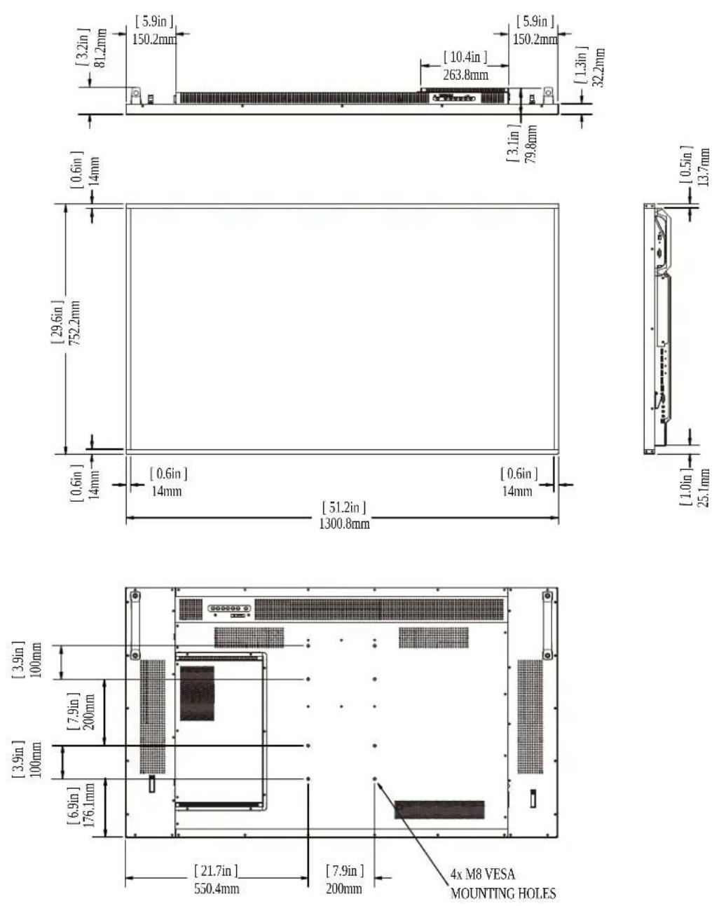
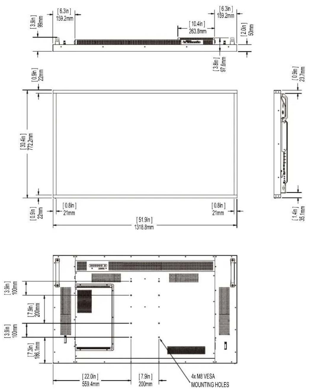
| Display Dimensions | Standard: 44.9" x 26" x 2.65"(1140.2mm x 659.6mm x 67.4mm)Touch: 44.9" x 26" x 3.34"(1140.2mm x 659.6mm x 84.9mm) | Standard: 51.2" x 29.6" x 3.14"(1300.8mm x 752.2mm x 79.8mm)Touch: 51.9" x 30.4" x 3.84"(1318.8mm x 772.2mm x 97.6mm) | Standard: 57.7" x 33.1" x 3.37"(1465.7mm x 841.3mm x 85.5mm)Touch: 58.4" x 33.8" x 4.06"(1483.5mm x 858.5mm x 103.2mm) |
| Bezel Width | Standard: 0.83"(21.1 mm)Touch: 0.7"(17.7 mm) | Standard: 0.55"(14 mm)Touch: 0.87"(22 mm) | Standard: 0.66"(16.8 mm)Touch: 0.91"(23 mm) |
| Display Weight | Standard: 62 lbs (28 kg)Touch: 78 lbs (35 kg) | Standard: 89 lbs (41 kg)Touch: 118 lbs (53 kg) | Standard: 86 lbs (39 kg)Touch: 119 lbs (54 kg) |
| Mounting | VESA 200 mm x 200 mm | VESA 200 mm x 400 mm | VESA 400 mm x 400 mm |
| Fanless | Yes | ||
| Speakers | 10W x 2 built-in | ||
| Usage | |||
| Recommended Usage | 24 x 7 | ||
| Backlight E-LED | D-LED | ||
| Backlight Life 30,000 hours min | |||
| Power Source | |||
| Power Consumption (Typ.) | 115 W 135 W 170 W | ||
| BTU/hr (Typ.) 115W x 3.42 BTU = 393 BTU/hr 135W x 3.42 BTU = 462 BTU/hr 541 BTU/hr | |||
| Standby Power Consumption | < 0.5W | ||
| Input Voltage / Frequency | AC 100-240V50-60 Hz | ||
| OPS Power 12V / 8A | |||
| Environment | |||
| Storage Temperature Min | -4°F ~ Max 140°F (-20°C ~ 60°C) | ||
| Operating Temperature Min | 32°F ~ Max 104°F (0-40°C) at up to 3000 m | ||
| Humidity 20-85% RH | |||
| Approvals FCC Class A, cTUVus, CE | |||
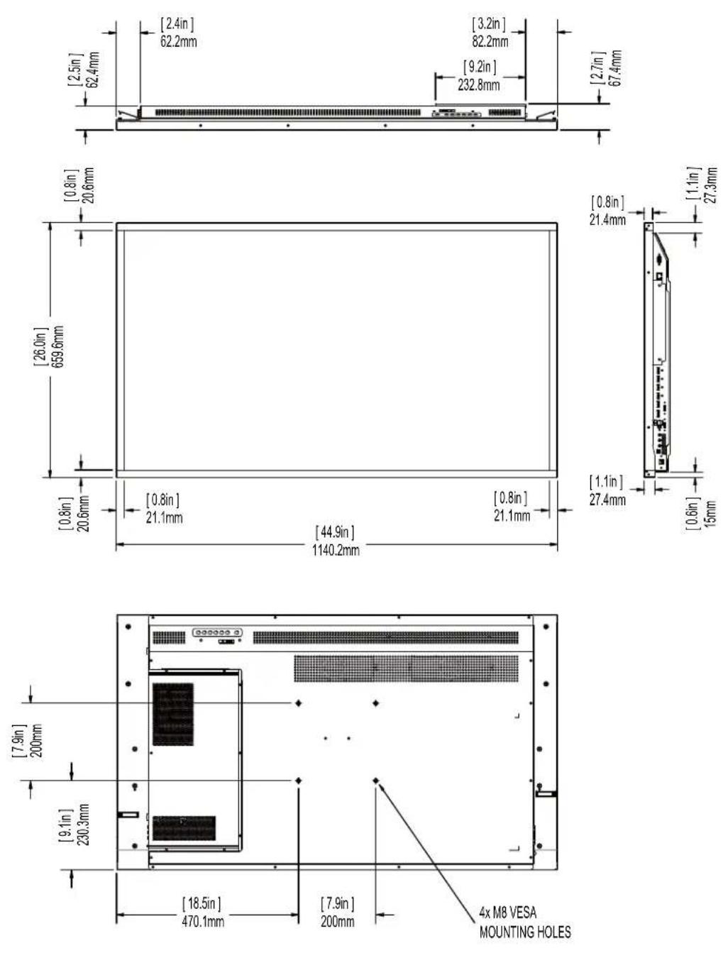
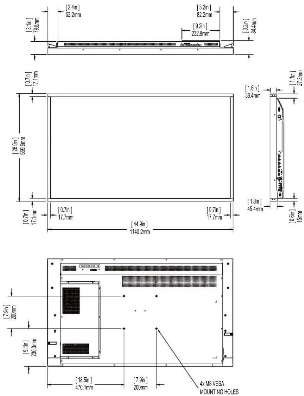
Dimensions
EP5024K
EP5024K-T
EP5824K
EP5824K-T
EP6524K
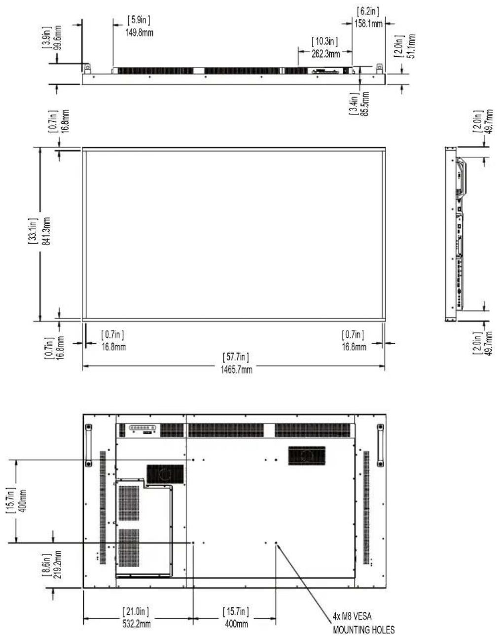
EP6524K-T
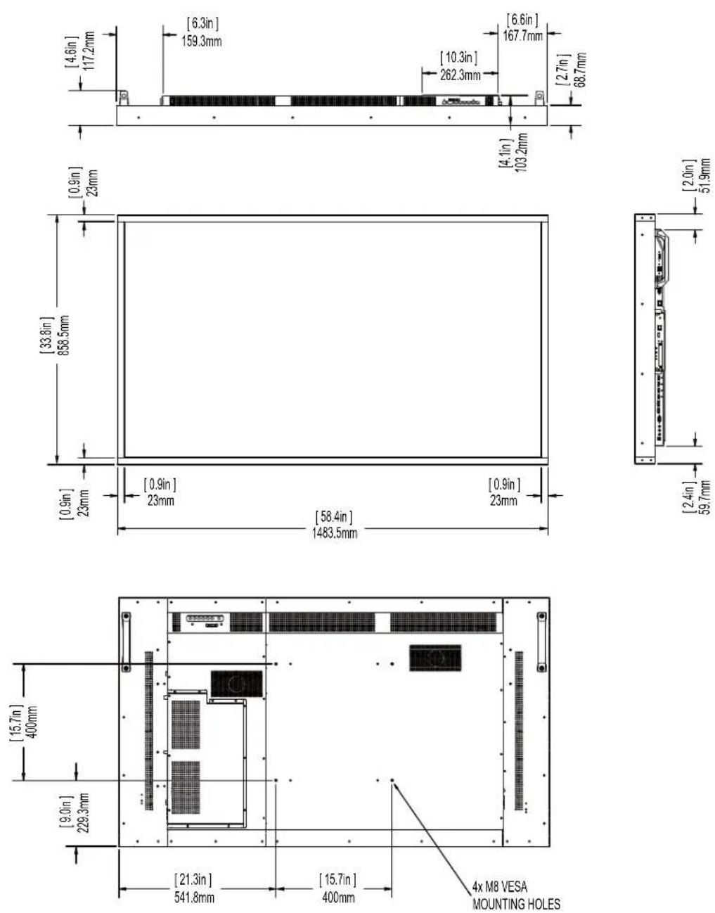
Troubleshooting
Before calling service personnel, please check the following table for a possible cause of the problem you are experiencing. Please note the following:
- Perform the adjustments according to "Operating the Display" on page 15.
- If the problem you have experienced isn't described below or you can't correct the problem, stop using the display and contact Planar's Technical Support Department. (See "Accessing Planar's Technical Support Website" on page 78)
| Issue Check for the following | |
| No image is displayed Make sure the correct source is selected. | |
| The image is not centered Make sure the input signal is compatible with this display. | |
| The remote control doesn't work | Make sure the batteries are new and are installed correctly.Ensure the remote is aimed at the IR sensor. |
| Make sure the remote control sensor is plugged in correctly. | |
| Make sure the remote is aimed towards the back of the display, where the sensor is located. | |
| The picture color looks poor Check the picture settings.Reset the display. | |
Accessing Planar's Technical Support Website
Go to http://www.planar.com/support to locate the following support documents and resources:
- User Guide
• RS232 User Manual - Touchscreen drivers
- Standard warranties
- Planar support hotline number and email
Index
A
accessory kit, 8
adjusting volume, 23
administrator in web service, 60
audio settings menu, 31
authentication configuration page, 60
avoiding temporary image retention, 4
B
basic settings menu, 24
batteries
changing in the remote, 22
C
cable clamps
installation, 10
cleaning the display, 7
Connecting the Touchscreen, 47
cooling requirements, 6
D
default setting
loading in web service, 61
dimensions, 71
display settings menu, 24
E
exemptions for product use, 8
H
HD-SDI board
installing, 14
I
image settings menu, 27
input source
selecting, 24
installation, 12
cable clamps, 10
OPS expansion slot, 14
safety precautions, 2
introduction, 1
ip system configuration, 60
L
LAN control, 48
locking, 21
M
menus
audio settings, 31
basic settings, 24
display settings, 24
image settings menu, 27
using, 24
N
navigating, 23
navigating menus, 23
network interface
resetting, 64
normal usage guidelines, 6
0
OPS expansion slot
installation, 14
osd menus, 33, 35
unlocking, 21
P
package contents, 8
product usage exemptions, 8
R
recommended usage, 4
remote control
changing the batteries, 22
using, 19
resetting the network interface, 64
RS232 network connection, 48
S
safety
during installation, 3
information, 2
precautions, 2
precautions during use, 4
selecting input source, 24
service plans, ii
signal compatibility, 65
signal source input, 24
SMTP setup page, 63
specifications, 69
supported timings, 65
system ip configuration page, 60
system status page, 59, 61
T
temporary image retention
avoiding, 4
definition, 4
timings, 65
TIR see temporary image retention
touchscreen
using the touchscreen, 47
troubleshooting, 77
turning off the displays, 23
turning on the displays, 22
U
unpacking the displays, 8
using the remote, 16
V
VCOM
configuration, 49
driver installation, 59
vesa mounts, 6
volume, 23
W
warranty
exemptions, 8
information, ii
web service, 58
administrator, 60
authentication configuration, 60
loading default setting, 61
reset device, 64
SMTP setup page, 63
system ip configuration, 60
system status, 59
system status page, 61