
353 - Measurement FLUKE - Free user manual and instructions
Find the device manual for free 353 FLUKE in PDF.


| Product Type | Hand-held Clamp Meter |
| Model | 353 |
| Brand | Fluke |
| Dimensions (L x W x D) | 300 mm x 98 mm x 52 mm (12 in x 3.75 in x 2 in) |
| Weight | 0.814 kg (1.8 lb) |
| Power Supply | 6 AA/LR6 batteries (1.5 V each) |
| Display | Digital LCD with backlight |
| Jaw Size | 58 mm (2.28 in) diameter |
| Current Measurement | AC, DC, AC+DC true RMS up to 2000 A (1000 Hz) |
| Voltage Measurement (355 only) | AC, DC, AC+DC true RMS up to 1000 V (1 kHz) |
| Inrush Current Measurement | Yes, dedicated button |
| Frequency Measurement | 5.0 Hz to 1 kHz |
| Resistance Measurement (355 only) | 400 Ω to 400 kΩ |
| Continuity Test (355 only) | Beeper on below 30 Ω |
| Key Functions | Hold, Zero, Hz, Low Pass Filter, Min Max, Inrush, Range, Backlight, Auto Power Off (20 min) |
| Safety Rating | CAT IV 600 V, CAT III 1000 V |
| Operating Temperature | 0 °C to 50 °C (32 °F to 122 °F) |
| Storage Temperature | -20 °C to 60 °C (-4 °F to 140 °F) |
| Humidity (Operating) | 0 to 95% non-condensing |
| IP Rating | IP42 (indoor use only) |
| Cleaning Instructions | Wipe with a damp cloth; do not use abrasives or solvents |
| Warranty | 3 years from purchase date |
| Included Accessories (353) | Software carrying case, 6 AA batteries, user manual |
| Spare Parts | C43 carrying case, TL224 test leads, TP2 test probes, AC285 alligator clips |
Frequently Asked Questions - 353 FLUKE
User questions about 353 FLUKE
0 question about this device. Answer the ones you know or ask your own.
Ask a new question about this device
Download the instructions for your Measurement in PDF format for free! Find your manual 353 - FLUKE and take your electronic device back in hand. On this page are published all the documents necessary for the use of your device. 353 by FLUKE.
USER MANUAL 353 FLUKE
© 2007 Fluke Corporation, All rights reserved. Printed in China.
All product names are trademarks of their respective companies.
LIMITED WARRANTY AND LIMITATION OF LIABILITY
This Fluke product will be free from defects in material and workmanship for three years from the date of purchase. This warranty does not cover fuses, disposable batteries, or damage from accident, neglect, misuse, alteration, contamination, or abnormal conditions of operation or handling. Resellers are not authorized to extend any other warranty on Fluke's behalf. To obtain service during the warranty period, contact your nearest Fluke authorized service center to obtain return authorization information, then send the product to that Service Center with a description of the problem.
THIS WARRANTY IS YOUR ONLY REMEDY. NO OTHER WARRANTIES, SUCH AS FITNESS FOR A PARTICULAR PURPOSE, ARE EXPRESSED OR IMPLIED. FLUKE IS NOT LIABLE FOR ANY SPECIAL, INDIRECT, INCIDENTAL OR CONSEQUENTIAL DAMAGES OR LOSSES, ARISING FROM ANY CAUSE OR THEORY. Since some states or countries do not allow the exclusion or limitation of an implied warranty or of incidental or consequential damages, this limitation of liability may not apply to you.
Fluke Corporation
P.O. Box 9090
Everett, WA 98206-9090
U.S.A.
Fluke Europe B.V.
P.O. Box 1186
5602 BD Eindhoven
The Netherlands
Table of Contents
Title
Page
Introduction ....1
Contacting Fluke ....1
Safety Information .... 2
Features .... 5
Display....7
Using the Meter....8
Measuring AC or DC Current....6
Measuring Inrush Current....9
Measuring AC and DC Voltage (355 only)....10
Testing Continuity (355 only)....12
Measuring Resistance (355 only)....13
Maintenance....14
Cleaning the Meter....14
Changing the Batteries....14
User Replaceable Parts .... 14
Specifications .... 15
Electrical Specifications .... 15
Standards and Agency Approval Specifications .... 18
Environmental Specifications .... 18
353/355
Users Manual
List of Tables
Table Title Page
- Explanation of Symbols...... 4
- Features and Buttons 5
- Rotary Switch Positions.... 6
- Display....
353/355
Users Manual
List of Figures
Figure Title Page
- Feature Locations.... 5
- The Display 7
- Connecting the Meter 8
- Measuring Inrush Current....9
- AC Voltage Measurement 10
- DC Voltage Measurement 11
- Measuring Continuity.... 12
- Measuring Resistance.... 13
353/355
Users Manual
Clamp Meter
Introduction
The Fluke 353 and 355 are hand-held battery-operated Clamp Meters (the Meter). Both Meters measure ac, dc true rms, inrush current and frequency; The 355 also measures ac, dc, true rms voltage, and resistance.
The Meter ships with:
• TL224 Test leads (355 only)
• AC285 Clips (355 only)
• TP74 Test Probes (355 only)
- Soft carrying case
- 6 AA/LR6 Batteries, installed
• 353/355 Users Manual (7 languages)
Contacting Fluke
To contact Fluke, call one of the following telephone numbers:
USA: 1-888-99-FLUKE (1-888-993-5853)
Canada: 1-800-36-FLUKE (1-800-363-5853)
Europe: +31 402-675-200
Japan: +81-3-3434-0181
Singapore: +65-738-5655
Anywhere in the world: +1-425-446-5500
Or visit Fluke's Web site at: www.fluke.com.
Register the Meter at: http://register.fluke.com
Safety Information
⚠️⚠️Warnings: Read First
To avoid possible electric shock or personal injury:
- Use the Meter only as specified in this manual or the protection provided by the Meter might be impaired.
- Avoid working alone so assistance can be rendered.
- Never measure ac current while the test leads are inserted into the input jacks.
- Do not use the Meter in wet or dirty environments.
- Do not use the Meter if it appears damaged. Inspect the Meter before use. Look for cracks or missing plastic. Pay particular attention to the insulation around the connectors.
- Inspect the test leads before use. Do not use them if insulation is damaged or metal is exposed.
- Check the test leads for continuity. Replace damaged test leads before using the Meter.
- Have the Meter serviced only by qualified service personnel.
- Use extreme caution when working around bare conductors or bus bars. Contact with the conductor could result in electric shock.
-
Do not hold the Meter anywhere beyond the tactile barrier. See Figure 1.
-
When measuring current, center the conductor in the clamp. See Figure 1.
- Do not apply more than the rated voltage, as marked on the Meter, between the terminals or between any terminal and earth ground.
- Remove test leads from the Meter before opening the Meter case.
- Never operate the Meter with the back cover removed or the case open.
- Never remove the back cover or open the case of an instrument without first removing the test leads or the jaws from a live conductor.
- Use caution when working with voltages above 30 V ac rms, 42 V ac peak, or 60 V dc. These voltages pose a shock hazard.
- Do not attempt to measure any voltage that might exceed the maximum range of the Meter- 600 V rms and 1 kHz or 1000 V dc.
- Use the proper terminals, function, and range for your measurements.
Clamp Meter
Safety Information
- Do not operate the Meter around explosive gas, vapor, or dust.
- When using probes, keep fingers behind the finger guards.
- When making electrical connections, connect the common test lead before connecting the live test lead; when disconnecting, disconnect the live test lead before disconnecting the common test lead.
- Disconnect circuit power and discharge all high-voltage capacitors before testing resistance, continuity, or diodes.
-
Use only 6 AA/LR6 batteries, properly installed in the Meter case, to power the Meter.
-
To avoid false readings that can lead to electrical shock and injury, replace the battery as soon as the low battery indicator (☐) appears. Check Meter operation on a known source before and after use.
- When servicing, use only specified replacement parts.
- Adhere to local and national safety codes. Individual protective equipment must be used to prevent shock and arc blast injury where hazardous live conductors are exposed.
- Do not use the Meter if the wear indicator in the jaw opening is not visible. See Figure 1.
Table 1. Explanation of Symbols
| Symbol | Explanation |
| ⚠️ | Risk of danger. Important information. Refer to operation instructions. |
| ⚠️ | Hazardous voltage |
| ⚡ | Application and removal from hazardous live conductors permitted |
| ☐ | Double insulated |
| ☐ | Battery |
| ⊥ | Earth Ground |
| ~ | Alternating Current |
| --- | Direct Current |
| ☒ | Do not dispose of this product as unsorted municipal waste. Go to Fluke’s web site for recycling information. |
| CE | Conforms to requirements of European Union and European Free Trade |
| N10140 | Conforms to relevant Australian standards |
| CAT III | Equipment is designed to protect against transients in equipment in fixed-equipment installations, such as distribution panels, feeders and short branch circuits, and lighting systems in large buildings. |
| CAT IV | Equipment is designed to protect against transients from the primary supply level, such as an electricity meter or an overhead or underground utility service. |
| SR* | Canadian Standards Association |
Features
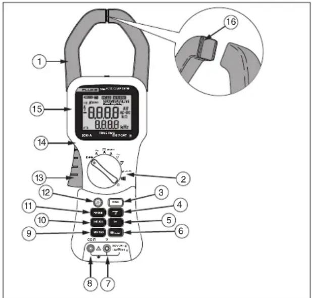
See Figure 1 and Tables 2 and 3 for a list of features.
fbq03.eps
Figure 1. Feature Locations (355 shown)
Table 2. Features and Buttons
| Number | Description |
| 1 | Current sensing clamp |
| 2 | Rotary function switch |
| 3 | Hold button- freezes the display reading and releases the reading when pressed a second time |
| 4 | Zero button- Clears last reading from the display and establishes a baseline for ac + dc and dc current readings. |
| 5 | Hz button- press to see frequency in the secondary display. |
| 6 | Low Pass Filter button- Press to turn on the low pass filter. The filter eliminates high frequency noise such as from a ASD or VFD motor speed controller. |
| 7 | Volts/Ohm input terminal. (355 only) |
| 8 | Common input terminal. (355 only) |
| 9 | Min Max button -When first pressed, the Meter shows maximum input. With subsequent presses, the minimum and the average inputs are shown. Hold for 2 seconds to exit min max mode. This function works in current, voltage and Frequency modes when activated. |
| 10 | Inrush button- Press this button to enter inrush mode. Press it a second time to exit. |
| 11 | Range button- press to change range or to turn off auto range. |
| 12 | Backlight button - Turns the backlight on and off. The backlight goes off after 5 minutes. |
| 13 | Jaw release |
| 14 | Tactile barrier⚠ Warning: To avoid injury, do not hold the Meter anywhere above the tactile barrier. |
| 15 | Display |
| 16 | Jaw wear indicator.⚠ Warning: To avoid injury, do not use the Meter if the wear indicator in the jaw opening is not visible. |
| N/A | Auto Power Off- The Meter turns off if there is no button pushed or rotary function switch operation for 20 minutes. Turn the Meter off and on to restart the Meter. This feature is disabled when the Meter is in Min Max mode. |
Table 3. Rotary Switch Positions
| Rotary Switch Position 353/355 | |||
| Position | Function | Position | Function |
| OFF | Meter is powered down | AC current | |
| DC current | AC + DC A | Combined ac + dc (true rms) current reading. | |
| Additional Positions (355 Only) | |||
| Position | Function | Position | Function |
| AC voltage | DC voltage | ||
| V_AC+DC | Combined ac + dc (true rms) voltage reading. | ||| | Continuity |
| Resistance | |||
Display
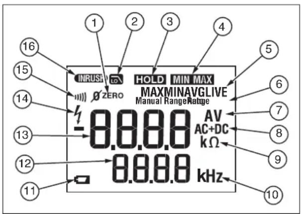
Figure 2 and Table 4 explain the display.
fbq01.eps
Figure 2. The Display
Table 4. Display
| Item | Explanation |
| 1 | Zero mode is active |
| 2 | Low pass filter is active |
| 3 | Hold mode is active |
| 4 | Min Max mode is active |
| 5 | Min, Max, Avg, or Live modes. Live mode is active with Min Max and designates the real-time reading. |
| 6 | Manual or Auto Range is active |
| 7 | Amps or Volts is active |
| 8 | AC and DC mode is active |
| 9 | Resistance mode is active |
| 10 | Frequency mode is active |
| 11 | Low Battery Symbol |
| 12 | Frequency display |
| 13 | Main display |
| 14 | Hazardous voltage present |
| 15 | Continuity symbol |
| 16 | Inrush mode is active |
Using the Meter
⚠ Warning
To avoid electric shock or personal injury:
- When measuring current, center the conductor in the clamp.
- When making current measurements, disconnect the test leads from the Meter.
- Keep fingers behind Tactile Barrier. See Meter Features.
Measuring AC or DC Current
To measure ac or dc current:
- Turn the rotary function switch to the proper current setting , , or _A^AC + DC .
- Open the clamp by pressing the jaw release and insert the conductor to be measured into the clamp.
- Close the clamp and center the conductor using the jaw alignment marks.
- View the current reading on the main display.
- When measuring ac or ac + dc current, press Hz to view the frequency reading on the frequency display.
⚠ Warning
To avoid possible electric shock or personal injury, if current is moving in opposite directions, place only ONE conductor into the clamp at a time. If current is moving in the same direction, more than one conductor may be placed into the clamp. See Figure 3.
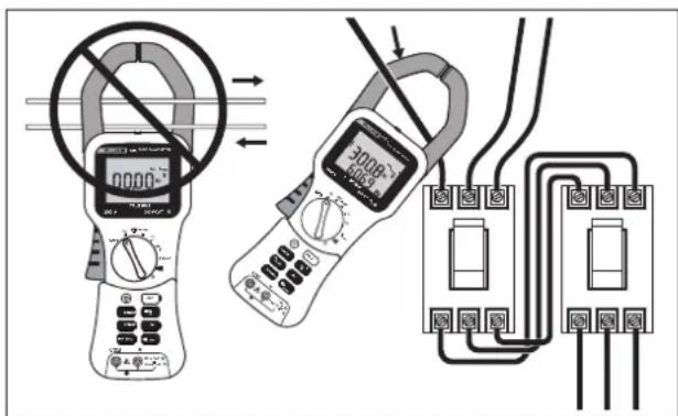
Figure 3. Connecting the Meter
Clamp Meter
Using the Meter
Measuring Inrush Current
Inrush current is surge current that occur when an electrical device is first powered on. Once the device has reached its normal working condition, the current stabilizes. See Figure 4.
To capture the inrush current reading:
- With the system under test powered down, place the source wire into the Meter jaws.
- Turn the knob to .
- Press INRUSH on the Meter.
- Power up the system under test. The inrush current is shown on the Meter display.
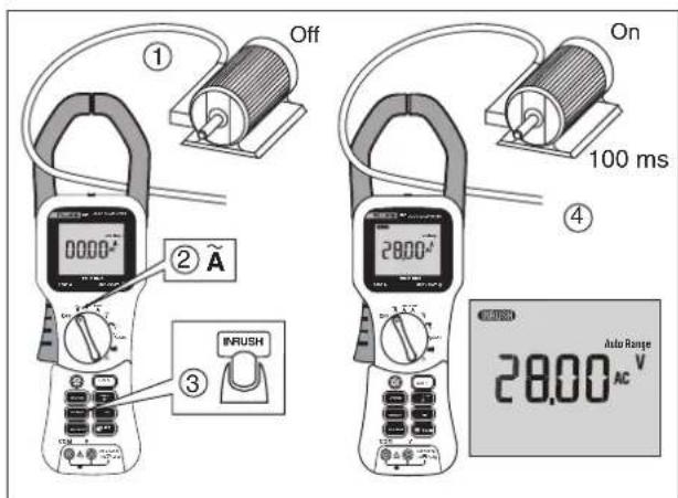
Figure 4. Measuring Inrush Current
fbq07.eps
Measuring AC and DC Voltage (355 only)
To measure ac or dc voltage:
- Turn the rotary function switch to , , or V^AC+DC .
- Connect the black test lead to the COM terminal and the red test lead to the V terminal. Before connecting the probes to the measurement points, add any clips to the probes that are necessary.
- Measure the voltage by touching the probes to the desired test points of the circuit.
- View the reading on the display.
- When measuring ac voltage, press Hz to view the frequency reading on the frequency display. See Figures 5 and 6.
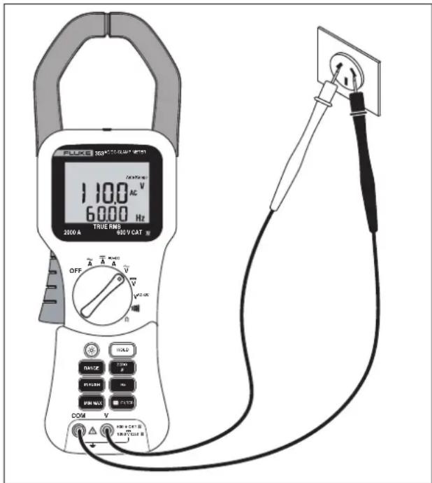
Figure 5. AC Voltage Measurement
fbq05.eps
Clamp Meter
Using the Meter
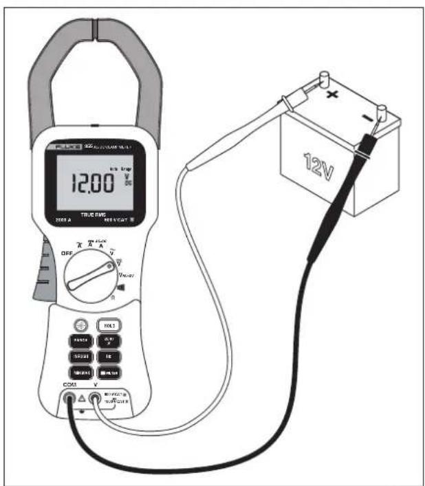
Figure 6. DC Voltage Measurement
1bxq06.eps
Testing Continuity (355 only)
⚠ Warning
To avoid electrical shock when testing continuity in a circuit, make sure the power to the circuit is turned off and all capacitors are discharged.
To test continuity:
- Connect the black test lead to the COM terminal and the red test lead to the V terminal.
- Remove power from the circuit being tested. Turn the rotary function switch to ·s .
- Connect the probes across the circuit or component to be tested.
- If the resistance is < 30 , the beeper sounds continuously, designating a short circuit (①). If the display reads OL, the circuit is open (②) or above 399.9 . See Figure 7.
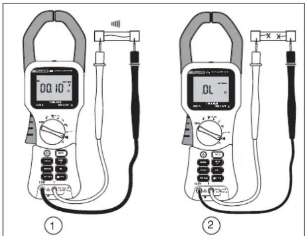
Figure 7. Measuring Continuity
Measuring Resistance (355 only)
⚠ Warning
To avoid possible electric shock or personal injury, when measuring resistance in a circuit, make sure the power to the circuit is turned off and all capacitors are discharged.
To measure resistance:
- Turn the rotary function switch to .
- Remove power from the circuit being tested.
- Connect the black test lead to the COM terminal and the red test lead to the V terminal.
- Measure the resistance by touching the probes to the desired test points of the circuit.
- View the reading on the display. See Figure 8.
Warning
To avoid electrical shock or personal injury, be aware that dangerous voltages may be present at the input terminals and may not be displayed
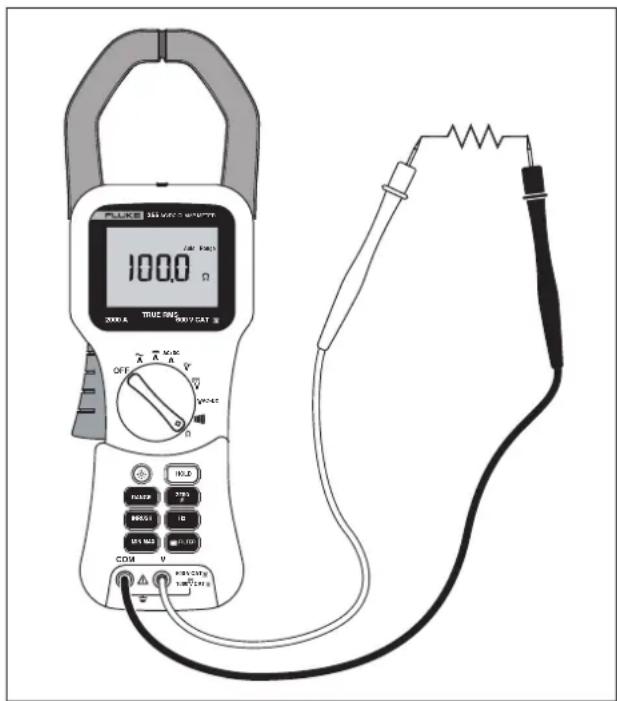
Figure 8. Measuring Resistance
fbq08.eps
Maintenance
Warning
To avoid electrical shock, or personal injury:
- Repairs or servicing not covered in this manual should be performed only by qualified personnel.
- Disconnect test leads from the Meter before removing its back cover.
- Never use the Meter with the back cover removed.
Caution
- To avoid contamination or static damage of the Meter, do not touch the circuit board without proper static protection.
- If the Meter is not going to be used for an extended time, remove the battery. Do not store the Meter in high temperature or high-humidity environments.
Cleaning the Meter
Caution
To avoid damaging the meter, do not use abrasives or solvents on this instrument.
Periodically clean the Meter by wiping it with a damp cloth.
Changing the Batteries
When battery voltage drops below the value required for proper operation, the battery symbol (☐) appears and the Meter beeps.
To change the batteries:
- Turn the Meter off and disconnect the test leads.
- Using a screwdriver, open the battery cover on the back of the Meter.
- Replace the batteries with six new AA/LR6 batteries. Observe correct polarity when installing the batteries.
- Close the back cover and tighten the screw.
User Replaceable Parts
Refer to Contacting Fluke for more information.
• C43 Soft carrying case
• TL224 1.5 m silicone rubber test leads
- TP2 Test Probes
- AC285 Alligator Clips
Clamp Meter
Specifications
Specifications
Electrical Specifications
Current Measurement 10 Hz to 100Hz
| Range | Resolution | Accuracy, | Trigger Level for Inrush | Trigger Level for Hz Filter OFF | Trigger Level for Hz Filter ON |
| 40 A 10 mA 1.5 | % rdg + 15 digits | 0.50 A 2.50 A 0.50 A | |||
| 400 A 100 mA 1 | 5 % rdg + 5 digits | 5.0 A 2.5 A 2.5 A | |||
| 2000 A; 1400 ac rms | 1 A 1.5 % rdg + 5 digits | 5 A | 8 A | 8 A |
Current Measurement 100.1 Hz to 1 kHz
| Range | Resolution | Accuracy >10 A |
| 40 A | 10 mA | 3.5 % rdg + 15 digits |
| 400 A | 100 mA | 3.5 % rdg + 5 digits |
| 2000 A; 1400 ac rms | 1 A | 3.5 % rdg + 5 digits |
Voltage Measurement (355 only) 10 Hz to 100 Hz
600 and 1000 V ranges have 10 % over range to 660 and 1100 V respectively.
| Range | Resolution | Accuracy | Trigger Level for Hz Filter OFF | Trigger Level for Hz Filter ON |
| 4 V 1 mV 1 % rdg + 10 digits 0.050 V 0.050 V | ||||
| 40 V 10 mV 1 % rdg + 5 digits 0.25 V 0.25 V | ||||
| 400 V 100 mV 1 % rdg + 5 digits 6 V 6 V | ||||
| 600 V AC RMS 1 V 1 % rdg + 5 digits 6 V 6 V | ||||
| 1000 V DC | 1 V 1 % rdg + 5 digits N/A | N/A |
Voltage Measurement (355 only) 100.1 Hz to 1 kHz
600 and 1000 V ranges have 10 % over range to 660 and 1100 V
| Range | Resolution | Accuracy |
| 4 V 1 mV | 3 % rdg + 10 | digits |
| 40 V 10 mV | 3 % rdg + 5 | digits |
| 400 V 100 mV | 3 % rdg + | 5 digits |
| 600 V AC RMS 1 V | 3 % rdg + 5 digits | |
Ohms Measurement (355 only)
| Range | Resolution | Accuracy |
| 400 Ω | 0.1 Ω | 1.5 % + 5 digits |
| 4 k Ω | 1 Ω | 1.5 % + 5 digits |
| 40 k Ω | 10 Ω | 1.5 % + 5 digits |
| 400 k Ω | 100 Ω | 1.5 % + 5 digits |
Clamp Meter
Specifications
Continuity Beeper (355)
On at ≤ 30
Off at ≥ 100 Ω
Frequency Measurement
Measurement Range 5.0 Hz to 1 kHz
Resolution 0.1 Hz (15 Hz to 399.9 Hz)
1 Hz ( 400 Hz to 1 kHz)
Accuracy
5.0 to 100 Hz 0.2% + 2 counts
Accuracy
100.1 Hz to 1 kHz 0.5 % + 5 counts
Trigger Level Refer to current and
voltage tables
General Specifications
Batteries: 6-1.5 V AA NEDA 15 A or IEC LR6
Test Leads: Rated to 1000 V
Weight: 1.8 lb (.814 kg)
Jaw Size: 2.28 inches (58 mm)
Dimensions (L x W x D): 12 inches x 3.75 inches x
2 inches (300 mm x 98 mm x 52 mm)
Safety Rating: IEC 61010-2-032, 600 V CAT IV,
1000 V CAT III
Standards and Agency Approval Specifications
Design
Standards and
Compliance
Agency
Approvals
Over-voltage
Category
EN61010-032 CAT IV 600 V.
IEC/EN 61326-1:1997


N10140
IEC61010-1 CAT III 1000 V,
CAT IV 600 V
Environmental Specifications
Operating
32 °F to + 122 °F
Témperature
(0 °C to +50 °C)
Storage
-4 °F to 140 °F
Temperature
(-20 °C to +60 °C)
Operating
0 to 95 % (non-condensing)
Humidity
Operating
2000 m
Altitude
Storage
10,000 m
Altitude
IP Rating
42 (indoor use only)
Drop Test
1 m
Requirements
EMI, RFI, EMC
FCC part 15, IEC/EN 61326-1:1997
class B, IEC/EN 61326:1997 3V/m,
performance criteria B, EN61325
Temperature
Current: 0.1 % of reading per °C
Coefficients
outside 22-24 °C
Voltage: 0.1 % of reading per °C
outside 22-24 °C
- LIMITED WARRANTY AND LIMITATION OF LIABILITY
- Table of Contents
- Title
- Page
- List of Tables
- Table Title Page
- List of Figures
- Figure Title Page
- Clamp Meter
- Introduction
- Contacting Fluke
- Safety Information
- ⚠️⚠️Warnings: Read First
- Features
- Display
- Using the Meter
- ⚠ Warning
- Measuring AC or DC Current
- Measuring Inrush Current
- Measuring AC and DC Voltage (355 only)
- Testing Continuity (355 only)
- To test continuity:
- Measuring Resistance (355 only)
- Warning
- Maintenance
- Caution
- Cleaning the Meter
- To avoid damaging the meter, do not use abrasives or solvents on this instrument.
- Changing the Batteries
- User Replaceable Parts
- Specifications
- Electrical Specifications
- Continuity Beeper (355)
- Frequency Measurement
- General Specifications
- Standards and Agency Approval Specifications
- Environmental Specifications
Brand : FLUKE
Model : 353
Category : Measurement