
C8618QT - Screen DELL - Free user manual and instructions
Find the device manual for free C8618QT DELL in PDF.


User questions about C8618QT DELL
0 question about this device. Answer the ones you know or ask your own.
Ask a new question about this device
Download the instructions for your Screen in PDF format for free! Find your manual C8618QT - DELL and take your electronic device back in hand. On this page are published all the documents necessary for the use of your device. C8618QT by DELL.
USER MANUAL C8618QT DELL
Dell C8618QT User's Guide

NOTE: A NOTE indicates important information that helps you make better use of your computer.

CAUTION: A CAUTION indicates potential damage to hardware or loss of data if instructions are not followed.

WARNING: A WARNING indicates a potential for property damage, personal injury, or death.
Copyright © 2017-2018 Dell Inc. or its subsidiaries. All rights reserved. Dell, EMC, and other trademarks are trademarks of Dell Inc. or its subsidiaries. Other trademarks may be trademarks of their respective owners.
2018-07
Rev. A03
Contents
About Your Display .... 5
Package Contents ....5
Product Features 8
Identifying Parts and Controls . . . . . . . . . . . . . . . . . . . . . . . . . . . . . . . . . . . . . . . . . . . . . . . . . . . . . . . . . . . . 9
Display Specifications 13
Plug-and-Play 25
LCD Display Quality and Pixel Policy. 25
Setting Up the Display 26
Connecting Your Display 26
Wall Mounting (Optional) 31
Remote Control. 32
Operating the Display....35
Turning on the Display 35
Touch OSD Launcher....35
Using the Touch Control Launcher. 36
Using the OSD lock function. 37
Using the On-Screen Display (OSD) Menu ..... 38
Dell Web Management for Displays 52
Troubleshooting 57
Self-Test 57

Built-in Diagnostics. 59
Common Problems 60
Product Specific Problems. 62
Touchscreen Problems 63
Universal Serial Bus (USB) Specific Problems 63
Ethernet Problems 64
Appendix. 65
Safety Instructions....65
FCC Notices (U.S. only) and Other Regulatory Information .....65
Contacting Dell 65
Setting Up Your Display 66
Maintenance Guidelines 68
Package Contents
Your display ships with the components shown below. Make sure that you have received all the components and contact Dell if something is missing.

NOTE: Some items may be optional and may not ship with your display. Some features or media may not be available in certain countries.
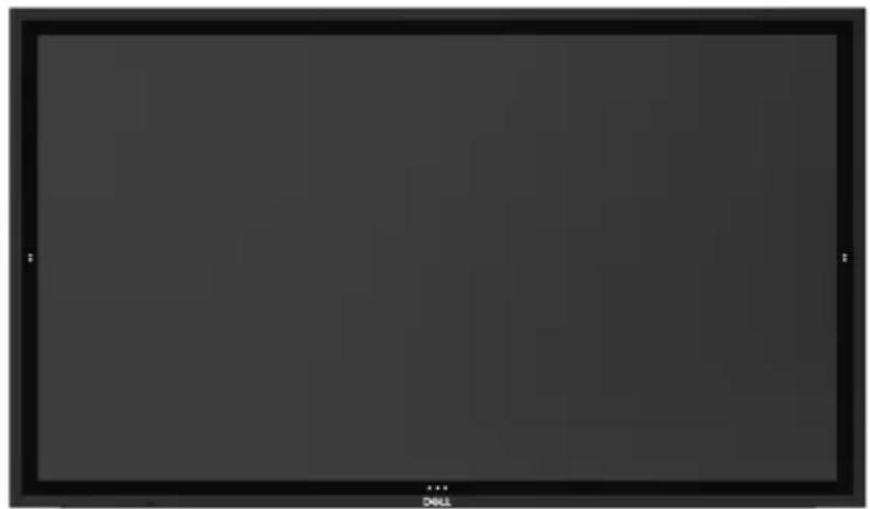
natural_image
Blank dark image with no visible content, text, or symbols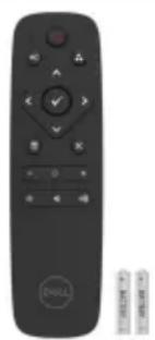
natural_image
Black DOLL remote control with scroll and button buttons (no text or symbols visible)Display
Remote Control & Batteries (AAA x 2)
Remote control holder
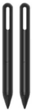 | Stylus x 2 | ||
 | Stylus holder | ||
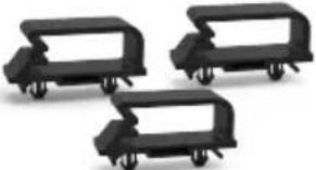 | Wire Saddle x 3 | ||
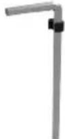 | Allen key with hook | ||
 | Power cable (varies by country) | ||
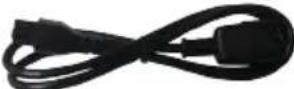 | Power cable for connecting Optiplex system to display (see Optiplex (Optional)) | ||
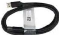 | USB 3.0 upstream cable (enables the USB ports on the display) | ||
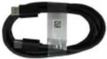 | DP cable (DP to DP) | ||
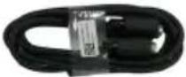 | VGA cable | ||
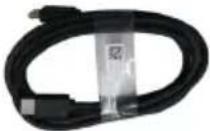 | HDMI cable | ||
 |  | 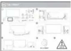 | Safety, Environmental and Regulatory InformationDisplayNote License KeyQuick Setup Guide |
Product Features
The Dell C8618QT display has an active matrix, thin film transistor (TFT), liquid crystal display (LCD), and LED backlight. The display features include:
- 217.427 cm (85.60-inch) active area display (Measured diagonally) 3840 x 2160 (16:9 aspect ratio) resolution, plus full-screen support for lower resolutions.
• Video Electronics Standards Association (VESA™) 600 x 400 mm mounting holes.
• Plug and play capability if supported by your system.
• On-Screen Display (OSD) adjustments for ease of set-up and screen optimization.
• Security lock slot.
• Supports Asset Management Capability.
• Arsenic-Free glass and Mercury-Free for Panel only.
• 0.5 W standby power when in the sleep mode.
• Easily setup with Dell Optiplex Mirco PC (Mirco Form Factor).
• Up to 20 points and 4 pens InGlass (TM) Touch technology. - Optimize eye comfort with a flicker-free screen.
- The possible long-term effects of blue light emission from the display may cause damage to the eyes, including eye fatigue or digital eye strain. ComfortView feature is designed to reduce the amount of blue light emitted from the display to optimize eye comfort.
Identifying Parts and Controls
Front view
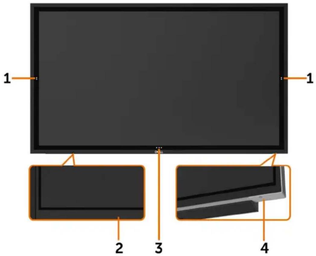
text_image
1 2 3 4 1| Label Description | |
| 1 Screen | drop down touch key |
| 2 IR Lens | |
| 3 | OSD Launcher touch key (For more information, see Operating the Display) |
| 4 Power | on/off button (with LED indicator) |
Back View
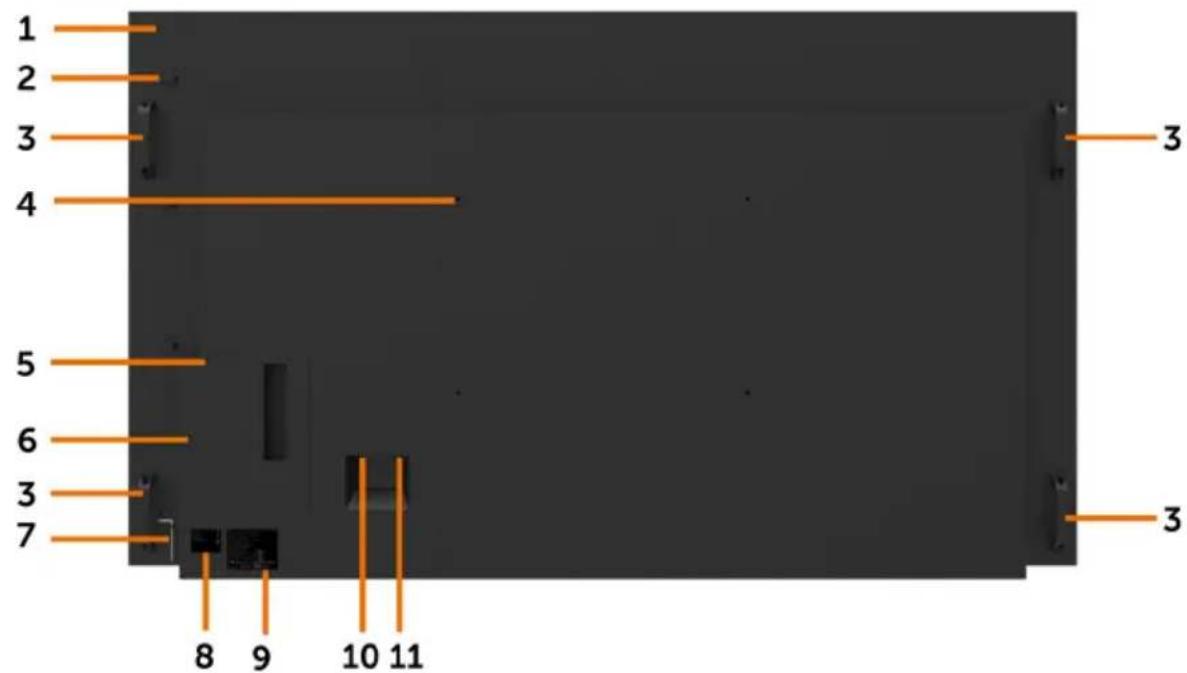
text_image
1 2 3 4 5 6 3 7 8 9 10 11 3| Label | Description Use | |
| 1 | Mounting provision for WR517 (optional item) | For Dell Wireless Receiver : WR517(optional) |
| 2 | Wire Saddle Use to handle display during installation | |
| 3 | Handle x 4 Use to move the display. | |
| 4 | VESA mounting holes (600 x 400 mm) To mount the display. | |
| 5 | Security lock slot Secures Optiplex with security cable lock (sold separately). | |
| 6 | Optiplex holder Use to hold a Micro Form Factor Optiplex PC. | |
| 7 | Allen key Use to tighten or loosen handle screws. | |
| 8 | Barcode, serial number, and Service Tag label | Refer to this label if you need to contact Dell for technical support. |
| 9 | Regulatory label List of approved regulatory labels. | |
| 10 | AC to optiplex (optional) | AC power to optiplex power adapter. |
| 11 | AC power connector | To connect the display power cable. |
Side View
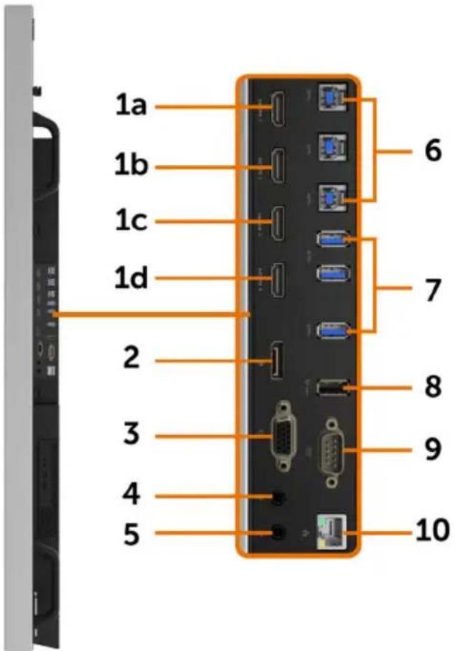
text_image
1a 1b 1c 1d 2 3 4 5 6 7 8 9 10| Label | Description Use | |
| 1a | HDMI 1 connector | Connect your computer with HDMI cable. |
| 1b | HDMI 2 connector | |
| 1c | HDMI 3 connector | |
| 1d | HDMI 4 connector | |
| 2 | DP connector Connect your computer with DP cable. | |
| 3 | VGA connector Connect your computer with VGA cable. | |
| 4 | Audio line-in port Analog audio (two channel) input. | |
| 5 | Audio line-out port Connect to external audio peripherals.Only supports 2-channel audio.NOTE: The audio line-out port does not support headphones. | |
| 6 | USB 3.0 upstream ports (3) | Connect the USB cable that comes with your display to the computer. Once this cable is connected, you can use the USB downstream connectors on the display and the touch screen function on the display. |
| 7 USB 3.0 downstream ports (3) | Connect your USB device.You can only use this connector after you have connected the USB cable to the computer and USB upstream connector on the display. | |
| 8 USB Dedicated charging port | USB 3.0 with 12.5 W - For WR517 Wireless Receiver(Optional) Power supply (5V/2.5A) | |
| 9 RS232 connector Remote management and control of display via RS232 | ||
| 10 | RJ-45 connector Remote | Network Management and control of display via RJ-45 |
Input sources and USB pairing
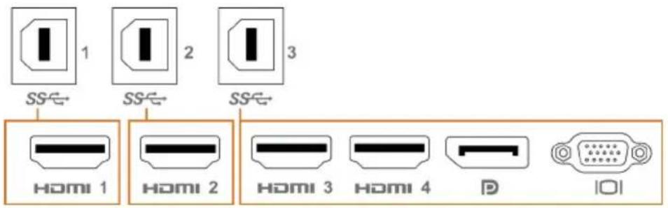
text_image
SS← 1 SS← 2 SS← 3 HOMI 1 HOMI 2 HOMI 3 HOMI 4 D IOI| Input sources USB upstream | |
| HDMI 1 USB 1 | |
| HDMI 2 USB 2 | |
| HDMI 3 | USB 3 |
| HDMI 4 | |
| DP | |
| VGA | |
Bottom View
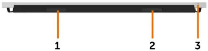
text_image
1 2 3| Label Description Use | ||
| 1, 2 | Speakers | |
| 3 | Power on/off button | |

Display Specifications
| Screen type Active matrix - TFT LCD | |
| Panel Type In-plane switching Technology | |
| Aspect ratio 16:9 | |
| Viewable image dimensions | |
| Diagonal 217.427 cm (85.60 inches) | |
| Active Area | |
| Horizontal 1895.04 mm (75.68 inches) | |
| Vertical 1065.96 mm (41.97 inches) | |
| Area | 2020039.84 mm^2 (3131.06 inches^2 ) |
| Pixel pitch 0.4935 mm x 0.4935 mm | |
| Pixel per inch (PPI) 51 | |
| Viewing angle | |
| Horizontal 178° (typical) | |
| Vertical 178° (typical) | |
| Panel brightness 360 cd/m^2 (typical) | |
| Contrast ratio 1200 to 1 (typical) | |
| Display screen coating | 7H, Anti-Smudge, Anti-Glare |
| Response Time | 8 ms typical (G to G), 12 ms max (G to G) |
| Color depth | 1.07 Billion colors |
| Color gamut | NTSC (72%) |
| Connectivity | ·1 x DP 1.2·1 x VGA·4 x HDMI 2.0·3 x USB 3.0 downstream port·1 x USB Dedicated charging portUSB 3.0 with 12.5W (ForWR517Wireless receiver(Optional) Power supply (5V/2.5A))·3 x USB 3.0 upstream port·1 x Analog 2.0 audio line out (3.5 mm jack)·1 x Analog 2.0 audio line in (3.5 mm jack)·1 x RJ-45·1 x RS232 |
| Border width (edge of display to active area) | 31.9 mm (Top)31.9 mm (Left/Right)31.9 mm (Bottom) |
| Cable management Yes | |
Touch
| Type InGlass Touch Technology (TM) | |
| Input Method Bare finger and stylus | |
| Interface USB HID Compliant | |
| Touch Driver Windows driver installation for Windows 7 | |
| Touch point | Up to 20 points touchUp to 4 pens |
NOTE: Touch, Pen and Eraser differentiation ready (functionality subject to application).
Support OS
| OS Version Touch Pen Eraser | ||||
| Windows | 7 Pro and Ultimate | 20 | 4 | 1 |
| 8, 8.1 | 20 | 4 | 1 | |
| 10 | 20 | 4 | 1 | |
| Chorme OS | Linux kernel version 3.15 (3.10) or later ^ | 20 | 4 (0) | 1 (0) |
| Android | 4.4 (KitKat) with Linux kernel 3.15 (3.10) or later | 20 | 4 (0) | 1 (0) |
| Other Linux based OS | Linux kernel 3.15 or later | 20 | 4 | 1 |
| macOS | 10.10, 10.11 | 1 (mouse ^2 ) | No | |
^1 Functionality of Linux kernel has been verified on Ubuntu 14.04 and Debian 8. Functionality of Chrome OS and Android with Linux kernel 3.15 needs confirmation.
^2 Mouse emulation in landscape mode. Full multi-touch requires additional drivers on the host system.
Touch sensor input accuracy
| Typ^1 | Max^2 | Unit | ||
| Touch sensor input accuracy | Center area^3 | 1.0 | 1.5 | mm |
| Edge area^4 | 1.2 | 2.0 | mm | |
1 Average accuracy at the specified input area.
2 95-percentile accuracy of specified input area.
^3 >20 mm from active touch area edge
^4 >20 mm from active touch area edge
Note that touch sensor input accuracy is defined relative to the active touch area as defined in

the reference drawing (listed in 8.1). The overall system accuracy, of touch co-ordinates relative to display co-ordinates, is directly affected by integration assembly tolerances.
Resolution Specifications
| Horizontal scan range 30 kHz to 140 kHz (DP/HDMI) | |
| Vertical scan range | 24 Hz to 75 Hz (DP/HDMI) |
| Maximum preset resolution 3840 x | 2160 at 60 Hz |
| Video display capabilities (DP & HDMI playback) | 480p, 576p, 720p, 1080i, 1080p, 2160p |
NOTE: VGA input resolution supported is 1920 x 1080 only.
Preset Display Modes
| Display Mode Horizontal Frequency (kHz) | Vertical Frequency (Hz) | Pixel Clock (MHz) | Sync Polarity (Horizontal/ Vertical) |
| 720 x 400 31.5 70.0 28.3 -/+ | |||
| 640 x 480 31.5 60.0 25.2 -/- | |||
| 640 x 480 | 37.5 | 75.0 | -/- |
| 800 x 600 | 37.9 60.0 40.0 +/+ | ||
| 800 x 600 | 46.9 | 75.0 | +/+ |
| 1024 x 768 | 48.4 | 60.0 | -/- |
| 1024 x 768 | 60.0 | 75.0 | +/+ |
| 1152 x 864 | 67.5 | 75.0 | +/+ |
| 1280 x 800 | 49.3 | 60.0 | +/+ |
| 1280 x 1024 | 64.0 | 60.0 | +/+ |
| 1280 x 1024 | 80.0 | 75.0 | +/+ |
| 1600 x 1200 | 75.0 | 60.0 | -/+ |
| 1920 x 1080 | 67.5 | 60.0 | +/+ |
| 2048 x 1152 | 71.6 | 60.0 | +/- |
| 2560 x 1440 | 88.8 | 60.0 | +/- |
| 3840 x 2160 | 65.68 | 30.0 | +/+ |
| 3840 x 2160 | 133.313 | 60.0 | +/+ |
Electrical Specifications
| Video input signals · Digital video signal for each differential linePer differential line at 100 ohm impedance· DP/HDMI/VGA signal input support | |
| Input voltage/ frequency/current 100-240 VAC / 50 or 60 Hz ± 3 Hz / 7 A (maximum) | |
| Output voltage/ frequency/current 100-240 VAC / 50 or 60 Hz ± 3 Hz / 2 A (maximum) | |
| Inrush current 120 V: 60 A (Max.) at 0 °C (cold start)240 V: 120 A (Max.) at 0 °C (cold start) |
Physical Characteristics
| Connector type · DP connector | VGA connectorHDMI connectorAudio line-outAudio line-inUSB 3.0 connectorUSB Dedicated charging port- supplying power of up to 5 V (max 2.5A) for connected devicesRJ-45RS232 connector |
| Signal cable type (in-box) DP, 3 m cable | HDMI, 3 m cableVGA, 3 m cableUSB 3.0, 3 m cable |
| Dimensions | |
| Height 1183.7 mm (46.60 inches) | |
| Width 1995.2 mm (78.55 inches) | |
| Depth 102 mm (4.02 inches) | |
| Weight | |
| Weight with packaging 148 kg (326.28 lb) | |
| Weight without packaging 123 kg (271.17 lb) | |
Environmental Characteristics
| Compliant Standards | |
| RoHS Compliant yes | |
| Temperature | |
| Operating 0 °C to 40 °C (32 °F to 104 °F) | |
| Non-operating -20 °C to 60 °C (-4 °F to 140 °F) | |
| Humidity | |
| Operating | 10% to 80% (non-condensing) |
| Non-operating 5% to 90% (non-condensing) | |
| Altitude | |
| Operating 5,000 m (16,404 ft) (maximum) | |
| Non-operating 12,192 m (40,000 ft) (maximum) | |
| Thermal dissipation 1535.46 BTU/hour (maximum) | |
Power Management Modes
If you have VESA's DPM-compliant video card or software installed in your PC, the display can automatically reduce its power consumption when not in use. This is referred to as power save mode*. If the computer detects input from the keyboard, mouse, or other input devices, the display automatically resumes functioning. The following table shows the power consumption and signaling of this automatic power saving feature.
| VESA Modes | Horizontal Sync | Vertical Sync | Video | Power Indicator Power Consumption | |
| Normal operation | Active Active | Active White | 450 | W (maximum)** | 212.8 W (typical) |
| Active-off mode | Inactive Inactive | Off White | (Glowing) | Less than 0.5 W | |
| Switch off | - | - | - | Off | Less than 0.5 W |
The OSD operates only in the normal operation mode. If you press any button in the active-off mode, the following message is displayed:
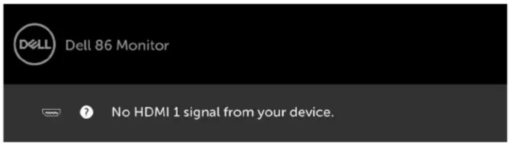
text_image
DELL Dell 86 Monitor ? No HDMI 1 signal from your device.*Zero power consumption in OFF mode can only be achieved by disconnecting the AC main cable from the display.
**Maximum power consumption with maximum luminance.
Activate the computer and the display to gain access to the OSD.

Pin Assignments
DP connector
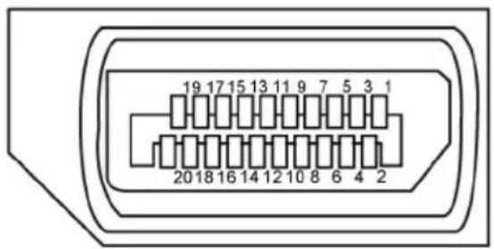
text_image
19 17 15 13 11 9 7 5 3 1 20 18 16 14 12 10 8 6 4 2| Pin number 20-pin side of the connected signal cable | |
| 1 ML3(n) | |
| 2 GND | |
| 3 ML3(p) | |
| 4 ML2(n) | |
| 5 GND | |
| 6 ML2(p) | |
| 7 ML1(u) | |
| 8 GND | |
| 9 ML1(p) | |
| 10 ML0(n) | |
| 11 GND | |
| 12 ML0(p) | |
| 13 CONFIG1/(GND) | |
| 14 CONFIG2/(GND) | |
| 15 AUX CH (p) | |
| 16 DP_Cable Detect | |
| 17 AUX CH (n) | |
| 18 Hot Plug Detect | |
| 19 GND | |
| 20 +3.3V DP_PWR | |
VGA connector
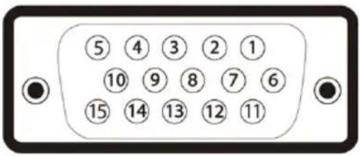
text_image
⑤ ④ ③ ② ① ⑩ ⑨ ⑧ ⑦ ⑥ ⑮ ⑭ ⑬ ⑭ ⑮| Pin number 15 | -pin side of the connected signal cable |
| 1 Video-Red | |
| 2 Video-Green | |
| 3 Video-Blue | |
| 4 NC | |
| 5 Self-test | |
| 6 GND-R | |
| 7 GND-G | |
| 8 GND-B | |
| 9 Computer 5 V / 3.3 V | |
| 10 GND-sync | |
| 11 GND | |
| 12 DDC data | |
| 13 H-sync | |
| 14 V-sync | |
| 15 DDC clock | |
HDMI connector
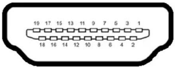
text_image
19 17 15 13 11 9 7 5 3 1 18 16 14 12 10 8 6 4 2| Pin number 19-pin side of the connected signal cable | |
| 1 TMDS DATA 2+ | |
| 2 TMDS DATA 2 SHIELD | |
| 3 TMDS DATA 2- | |
| 4 TMDS DATA 1+ | |
| 5 TMDS DATA 1 SHIELD | |
| 6 TMDS DATA 1- | |
| 7 TMDS DATA 0+ | |
| 8 TMDS DATA 0 SHIELD | |
| 9 TMDS DATA 0- | |
| 10 TMDS CLOCK+ | |
| 11 TMDS CLOCK SHIELD | |
| 12 TMDS CLOCK- | |
| 13 CEC | |
| 14 Reserved (N.C. on device) | |
| 15 DDC CLOCK (SCL) | |
| 16 DDC DATA (SDA) | |
| 17 DDC/CEC Ground | |
| 18 +5 V POWER | |
| 19 HOT PLUG DETECT |
RS232 connector
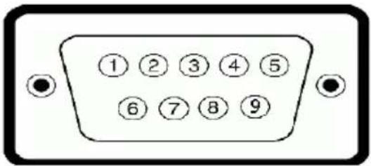
text_image
①②③④⑤ ⑥⑦⑧⑨| Pin number 9-pin side of the connected signal cable | |
| 1 - | |
| 2 RX | |
| 3 TX | |
| 4 - | |
| 5 GND | |
| 6 - | |
| 7 Not Used | |
| 8 Not Used | |
| 9 - | |
RJ-45 connector
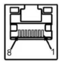
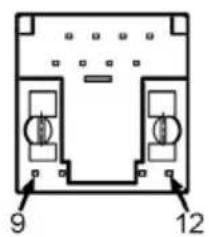
text_image
9 12| Pin number 12 | -pin side of the connected signal cable |
| 1 D+ | |
| 2 RCT | |
| 3 D- | |
| 4 D+ | |
| 5 RCT | |
| 6 D- | |
| 7 GND | |
| 8 GND | |
| 9 LED2_Y+ | |
| 10 LED2_Y- | |
| 11 LED2_G+ | |
| 12 LED2_G- |
Universal Serial Bus (USB)
This section gives you information about the USB ports available on your display.
Your computer has the following USB ports:
• 3 USB 3.0 upstream
3 USB 3.0 downstream
• 1 USB Dedicated charging port
Power supply port - the ports only for WR517 Wireless receiver Power supply (5V/2.5A).

NOTE: The display's USB ports work only when the display is on or in the power save mode. If you turn off the display and then turn it on, the attached peripherals may take a few seconds to resume normal functionality.
| Transfer speed Data rate Power consumption | |
| SuperSpeed 5 Gbps 4.5 W (Max., each port) | |
| Hi-Speed 480 Mbps 2.5 W (Max., each port) | |
| Full speed 12 Mbps 2.5 W (Max., each port) |
USB 3.0
upstream port
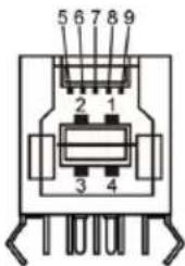
text_image
5 6 7 8 9 2 1 3 4USB 3.0
downstream port
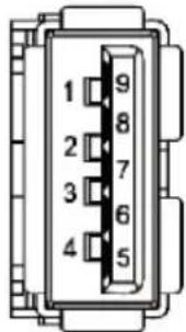
text_image
1 2 3 4 5 6 7 8 9| Pin number | Signal name | Pin number | Signal name |
| 1 VBUS 1 VBUS | |||
| 2 D- | 2 | D- | |
| 3 D+ | 3 | D+ | |
| 4 GND | 4 | GND | |
| 5 StdB_SSTX- | 5 StdA_SSRX- | ||
| 6 StdB_SSTX+ | 6 StdA_SSRX+ | ||
| 7 | GND_DRAIN | 7 | GND_DRAIN |
| 8 StdB_SSRX- | 8 StdA_SSTX- | ||
| 9 StdB_SSRX+ | 9 StdA_SSTX+ | ||
| Shell | Shield Shell Shield |

Plug-and-Play
You can install the display in any Plug-and-Play-compatible system. The display automatically provides the computer system with its extended display identification data (EDID) using display data channel (DDC) protocols so the computer can configure itself and optimize the display settings. Most display installations are automatic; you can select different settings if desired. For more information about changing the display settings, see Operating the Display.
LCD Display Quality and Pixel Policy
During the LCD display manufacturing process, it is not uncommon for one or more pixels to become fixed in an unchanging state which are hard to see and do not affect the display quality or usability. For more information on LCD Display Pixel Policy, see Dell support site at: http://www.dell.com/support/monitors.
Connecting Your Display

WARNING: Before you begin any of the procedures in this section, follow the Safety Instructions.
To connect your display to the computer:
- Turn off your computer.
- Connect the HDMI/DP/VGA/USB cable from your display to the computer.
- Switch on your display.
- Select the correct input source at Display OSD Menu and turn on your computer.
External PC connection
Connecting the USB cable
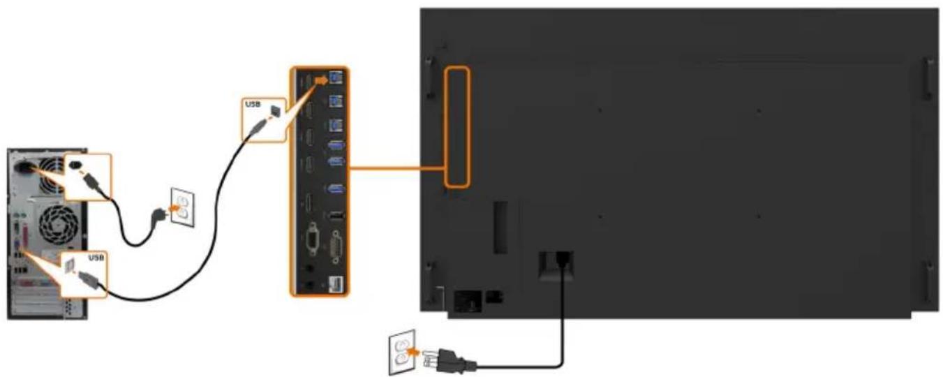
text_image
Diagram showing USB cable connection to a device panel, with labeled ports and cable connectionsNOTE: Refer to section on input source and USB pairing.

Connecting the HDMI cable
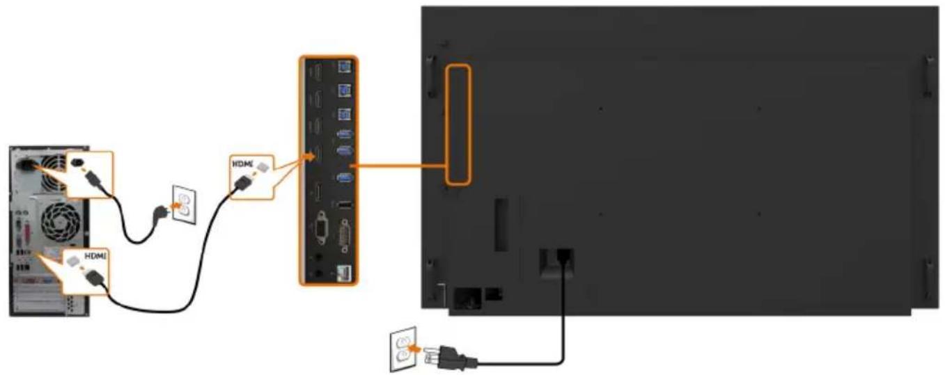
text_image
Diagram showing cable connection between a computer monitor and a rear panel, with labeled components including HDMI and power plug.Connecting the DP cable
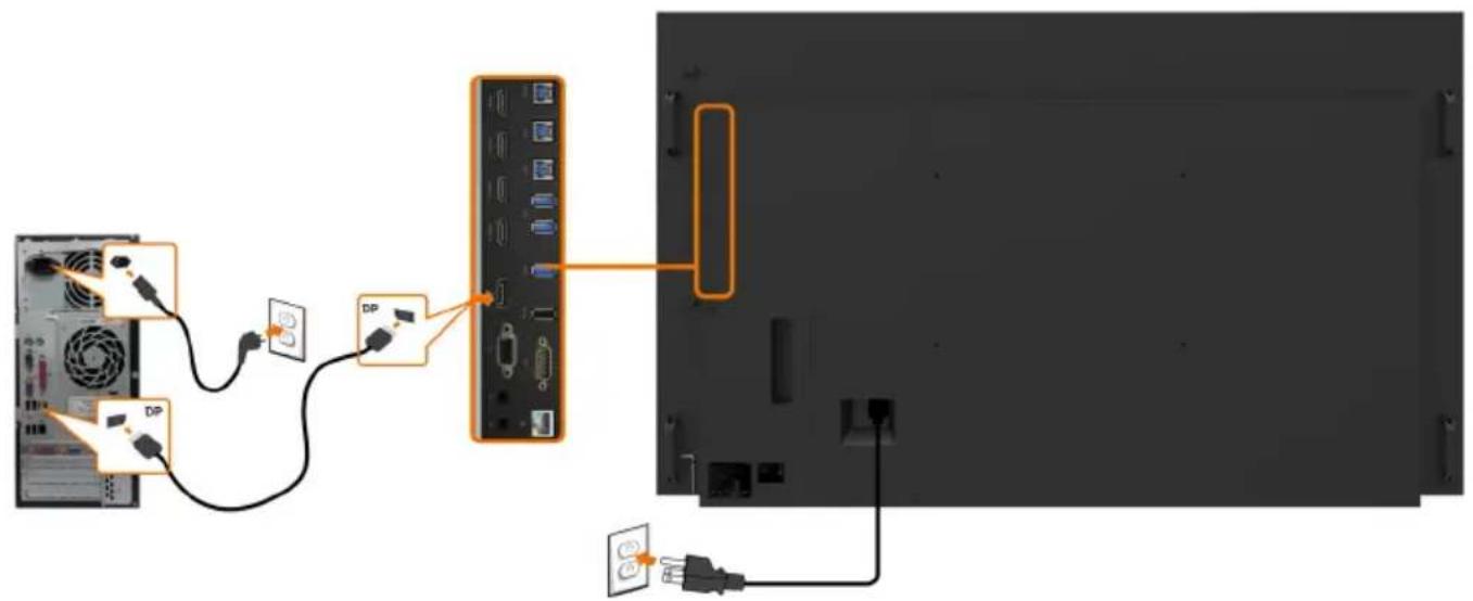
text_image
Diagram showing cable connection between a computer monitor and a rear panel, with labeled components like DP and power plug.Connecting the VGA cable
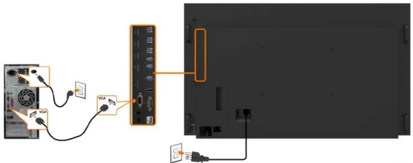
text_image
Diagram showing cable connection between a computer monitor and a separate panel, with VGA connectors and power plug connections.
Optiplex (Optional) Attaching the Optiplex
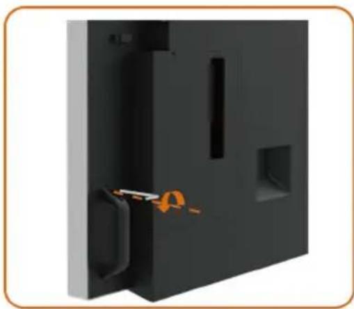
natural_image
3D rendering of a black rectangular electronic device with internal components and a small orange tool inserted (no text or symbols visible)- Loosening the handle by removing the top screw with the Allen key provided.
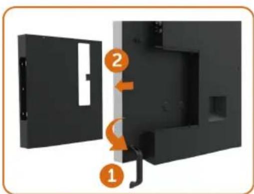
text_image
Diagram showing a device with labeled parts, including a numbered step indicator (1) and (2) pointing to a highlighted section.- Rotate handle.
- Remove the Optiplex holder.

text_image
Diagram showing three steps of a device mounting or installation, with numbered annotations indicating process flow.- Remove cable cover.
- Install Optiplex PC and power adapter into respective slot.
- Insert and organize the cables.
text_image
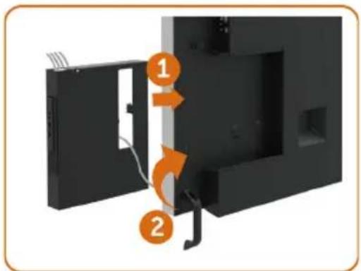
Diagram showing two labeled components of a device with arrows indicating flow or movement, numbered 1 and 2.- Slide Optiplex holder back into display.
- Restore handle to its original position.
Connecting the Optiplex
Connecting the HDMI cable
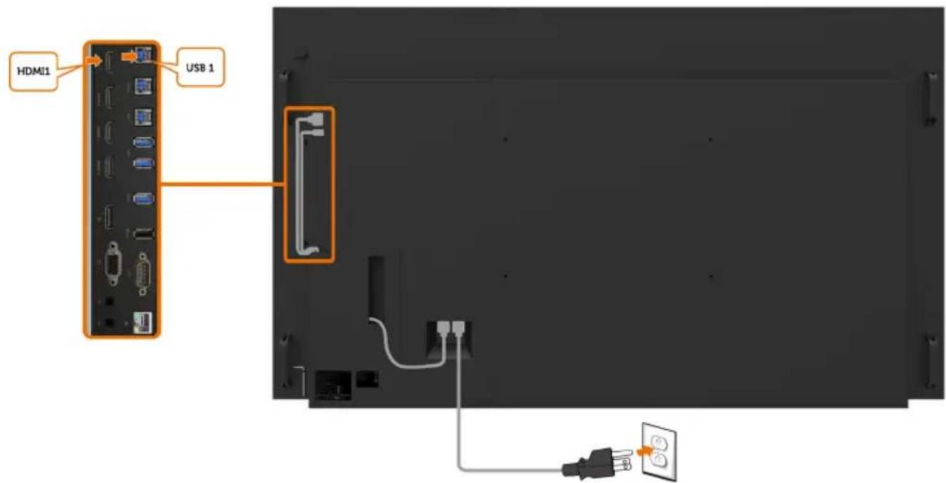
text_image
HDMI1 USB 1Connecting the DP cable
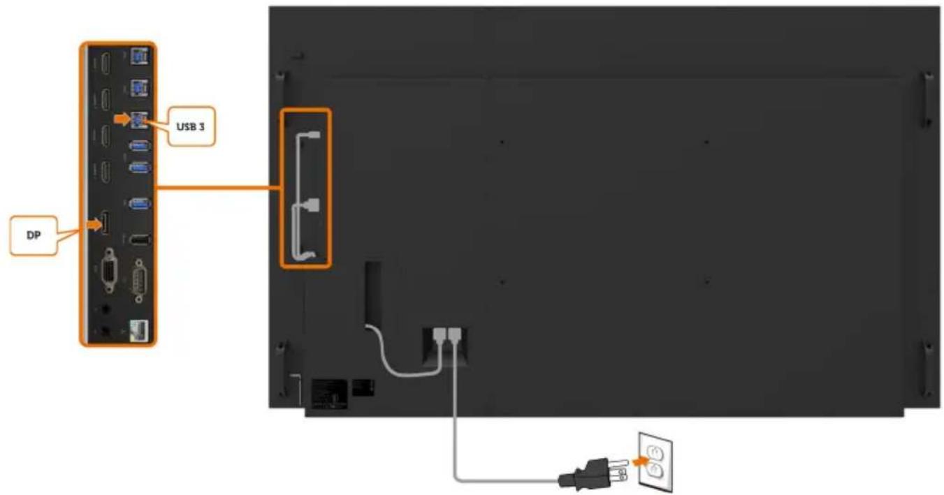
text_image
USB 3 DPConnecting the VGA cable
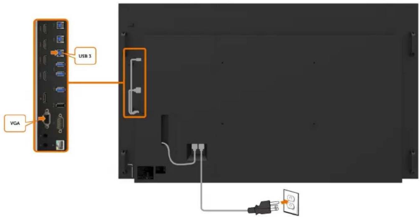
text_image
USB 3 VGA
Wall Mounting (Optional)
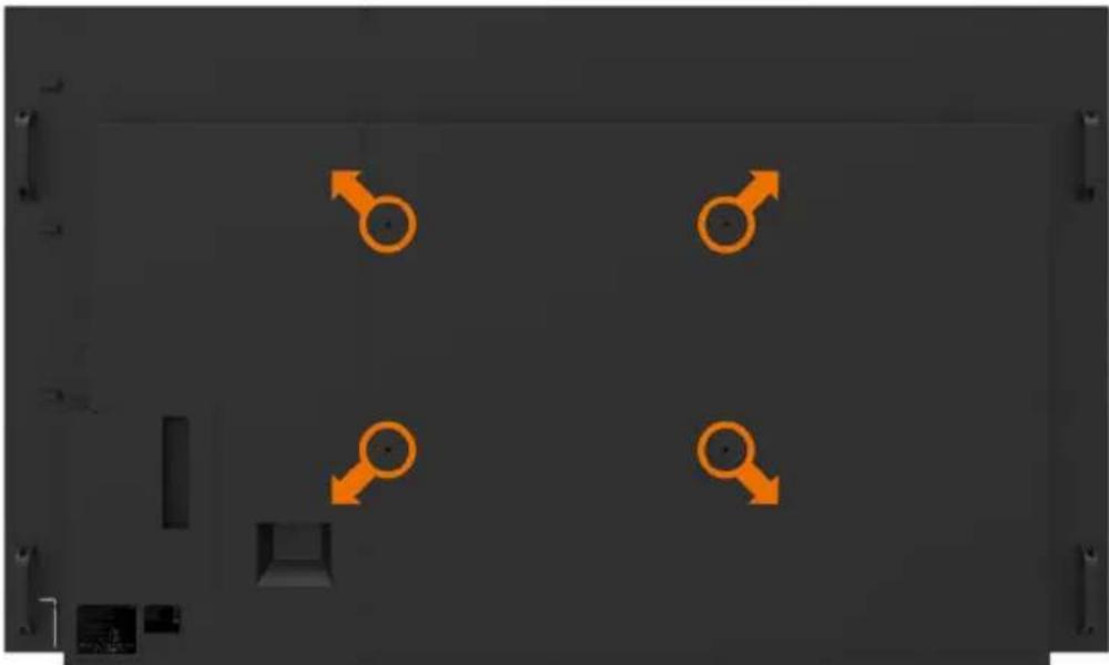
natural_image
Top-down view of a device layout with four orange male gender symbols on a dark background (no text or labels)(Screw dimension: M8 x 35 mm).
Refer to installation instruction that comes with the 3rd party wall mount that customer purchases. Vesa-compatible base mounting kit (600 x 400) mm.
-
Install Wall Plate to Wall.
-
Place the display panel on a soft cloth or cushion on a stable flat table.
-
Attach the mounting brackets from the wall mounting kit to the display.
-
Install Display to Wall Plate.
-
Ensure display is mounted vertically with no tilt forward or backward and a leveler is used to assist to mount the display.

NOTE:
- Do not attempt to wall mount the Touch Display by yourself. it should be installed by qualified installers.
- Recommended Wall Mount for this Display is can be found in the Dell support website at dell.com/support.

NOTE: For use only with UL or CSA or GS-listed wall mount bracket with minimum weight/load bearing capacity of 123 kg (271.17 lb).
Remote Control
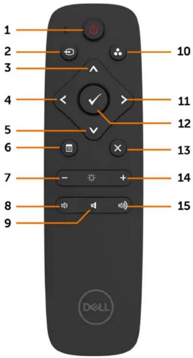
text_image
1 2 3 4 5 6 7 8 9 10 11 12 13 14 15 DELL1. Power On/Off
Switch this display on or off.
2. Input Source
Select input source. Press 📄 button to select from VGA or DP or HDMI 1 or HDMI 2 or HDMI 3 or HDMI 4.
Press √ button to confirm and exit.
3. Up
Press to move the selection up in OSD menu.
4. Left
Press to move the selection left in OSD menu.
5. Down
Press to move the selection down in OSD menu.
6. Menu
Press to turn on the OSD menu.
7. Brightness -
Press to decrease the Brightness.
8. Volume -
Press to decrease the Volume.
9. MUTE
Press to turn the mute function on/off.
10.Preset Modes
Display information about Preset Modes.
11. Right
Press to move the selection right in OSD menu.
12. OK
Confirm an entry or selection.
13. Exit
Press to exit the Menu.
14. Brightness +
Press to increase the Brightness.
15. Volume +
Press to increase the Volume.

Inserting the batteries in the remote control
The remote control is powered by two 1.5V AAA batteries.
To install or replace batteries:
- Press and then slide the cover to open it.
- Align the batteries according to the (+) and (−) indications inside the battery compartment.
- Replace the cover.
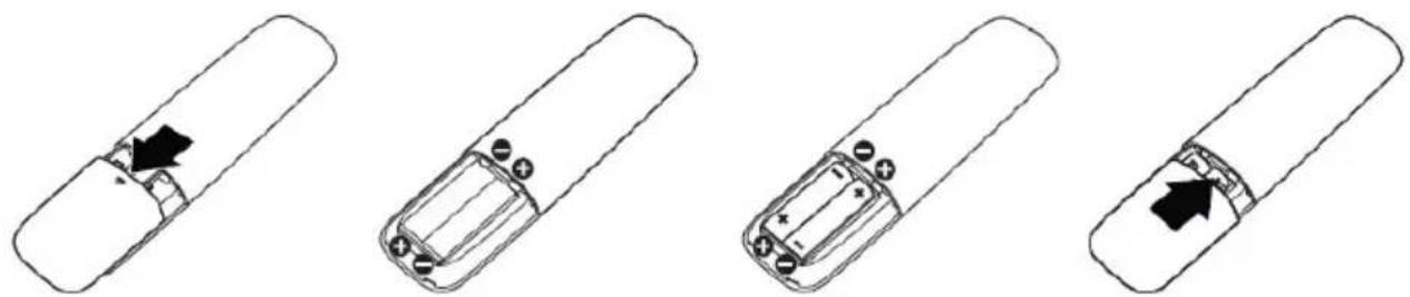
natural_image
Four line drawings of a cylindrical battery with internal components and arrows indicating movement or change (no text or symbols)
CAUTION: The incorrect use of batteries can result in leaks or bursting. Be sure to follow these instructions:
- Place "AAA" batteries matching the (+) and (−) signs on each battery to the (+) and (−) signs of the battery compartment.
• Do not mix battery types.
• Do not combine new batteries with used ones. It causes shorter life or leakage of batteries. - Remove the dead batteries immediately to prevent them from liquid leaking in the battery compartment. Don't touch exposed battery acid, as it can damage your skin.

NOTE: If you do not intend to use the remote control for a long period, remove the batteries.
Handling the remote control
• Do not subject to strong shock.
- Do not allow water or other liquids to splash on the remote control. If the remote control gets wet, wipe it dry immediately.
- Avoid exposure to heat and steam.
• Other than to install the batteries, do not open the remote control.
Operating range of the remote control
Point the top of the remote control toward the LCD display's remote sensor during button operation.
Use the remote control within a distance of about 8 m from remote control sensor or at a horizontal and vertical angle of within 15^ within a distance of about 5.6 m.

NOTE: The remote control may not function properly when the remote control sensor on the display is under direct sunlight or strong illumination, or when there is an obstacle in the path of signal transmission.
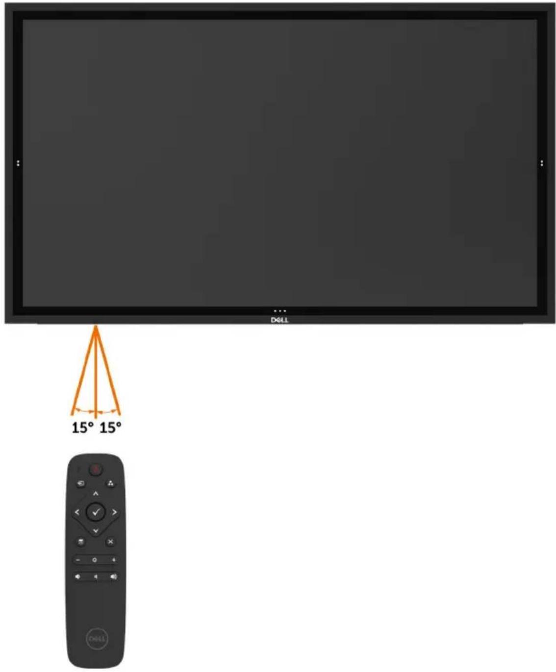
text_image
D4LL 15° 15°
Turning on the Display
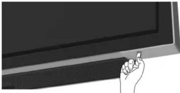
Press the Power button 📁 turn the display On and Off. The white LED indicates the display is On and fully functional. A glowing white LED indicates DPMS Power Save Mode.
natural_image
Illustration of a hand holding a flat-screen monitor (no text or symbols visible)Touch OSD Launcher
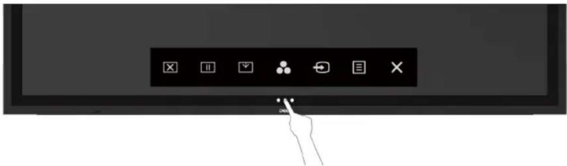
This display comes with a touch OSD functionalities. Press the OSD launcher touch key to access the functionalities.
natural_image
Hand interacting with a touchscreen display panel (no text or symbols visible)Using the Touch Control Launcher
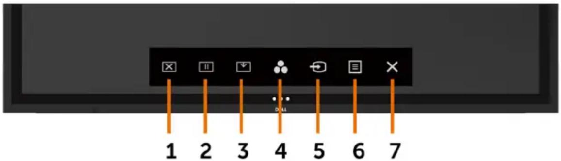
Use the touch control icons on the front of the display to adjust the characteristics of the image being displayed. As you use these icons to adjust the controls, an OSD shows the numeric values of the characteristics as they change.
text_image
1 2 3 4 5 6 7The following table describes the touch control icons:
| Touch Control icons Description | ||
| 1 |  | Use this icon to switch screen to black or white.Go to Menu to select screen off color. |
| Screen Off | Use touch key screen restore. | |
| 2 |  | To a freeze screen when press/activate.Use touch key screen restore. |
| Suspend | ||
| 3 |  | Screen Drop Down so that you can easily reach the top of the image. |
| Screen Drop Down | Use touch key screen restore. | |
| 4 |  | Use this icon to choose from a list of preset color modes. |
| Preset Modes | ||
| 5 |  | Use this icon to choose from a list of Input Source. |
| Input Source | ||
| 6 |  | Use this menu icon to launch the on-screen display (OSD) and select the OSD menu. |
| Menu | See Accessing the Menu System. | |
| 7 |  | Use this icon to go back to the main menu or exit the OSD main menu. |
| Exit | ||

Using the OSD lock function
- Press the OSD launcher touch key.
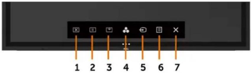
text_image
1 2 3 4 5 6 7- Touch and hold ✗ for 5 seconds. you can see following select option:
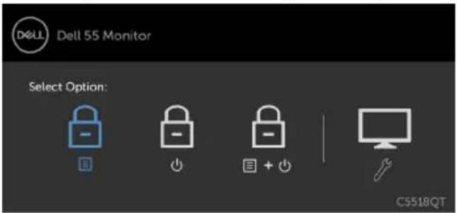
text_image
DELL Dell 55 Monitor Select Option: C5518QT
The following table describes the touch control icons:
Options Description
| 1 |  | Use this icon to lock OSD menu function. |
| OSD menu lock | ||
| 2 |  | Use this icon to lock power button from powering off. |
| Power-off button lock | ||
| 3 |  | Use this icon to lock OSD menu and power button from powering off. |
| OSD menu and power button lock | ||
| 4 |  | Use this icon to run the built-in diagnostics, seeBuilt-in Diagnostics. |
| Built-in Diagnostics |
- Touch and hold ✗ or 5 seconds, touch t ☑ unlock.
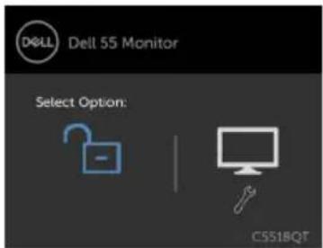
text_image
DELL Dell 55 Monitor Select Option: CSS1BQT

NOTE: This OSD lock feature is available from firmware version M2T103 or later.
Using the On-Screen Display (OSD) Menu
Accessing the Menu System

NOTE: Any changes you make using the OSD menu are automatically saved if you move to another OSD menu, exit the OSD menu, or wait for the OSD menu to disappear.
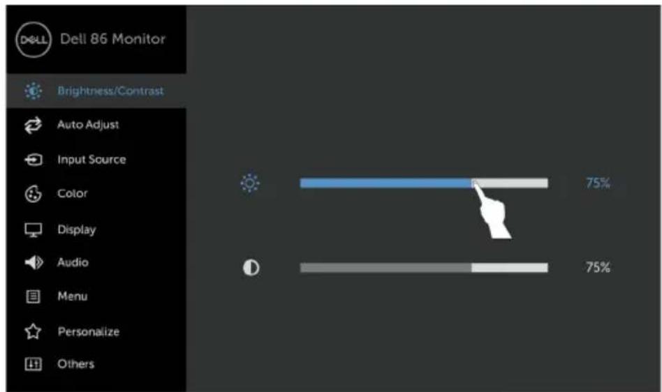
1 Press the button on the remote control or OSD Launcher touch key to launch the OSD menu.
bar
| Category | Value (%) | |---|---| | Auto Adjust | 75 | | Input Source | 75 | | Color | 75 | | Display | 75 | | Audio | 75 | | Menu | 75 | | Personalize | 75 | | Others | 75 |


Use the icons to adjust the image settings.
Touch control icon Description
1

Up

Down
Use the Up (increase) and Down (decrease) icons to adjust items in the OSD menu.

| 2 |  |  | Use the Left (decrease) and Right (increase) icons to adjust items in the OSD menu. |
| Left | Right | ||
| 3 |  | Use the OK icon to confirm your selection. | |
| OK | |||
| 4 |  | Use the Back icon to go back to the previous menu. | |
| Back |
Touch OSD Control
| Icon Menu and Submenus | Description | |
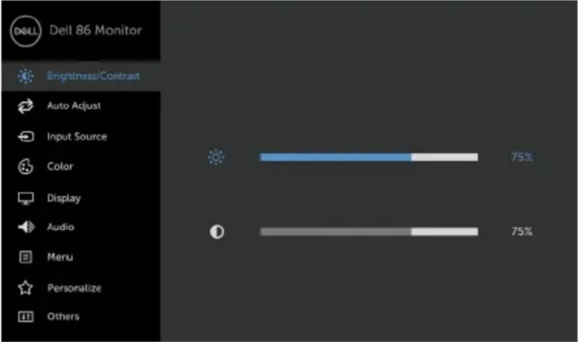
 | Brightness/Contrast | Use this menu to activate Brightness/Contrast adjustment. |
 | ||
| < > × | ||
Brightness Brightness adjusts the luminance of the backlight
(minimum 0; maximum 100).
Touch the button to increase brightness.
Touch the moon to decrease brightness.
Contrast
Adjust the Brightness first, and then adjust Contrast only if further adjustment is necessary.
Touch the icon to increase contrast and Touch the icon to decrease contrast (between 0 and 100).
Contrast adjusts the difference between darkness and lightness on the display.
Icon Menu and
Submenus
Description

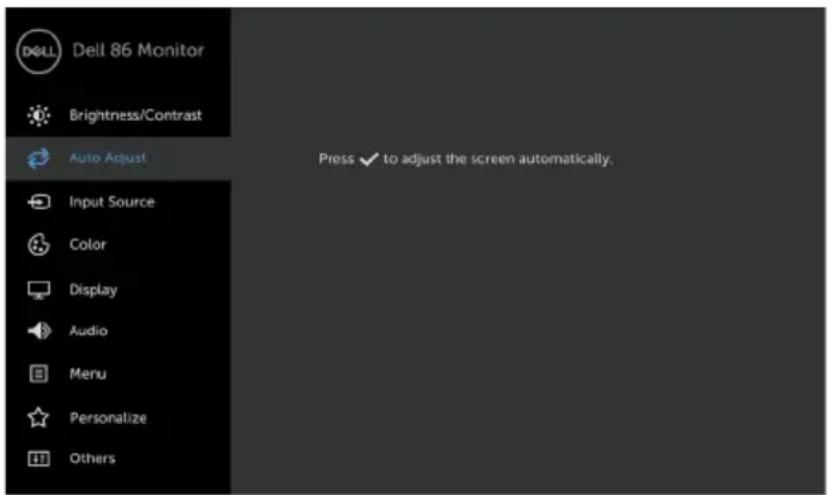
Auto Adjust Even though your computer recognizes your display on startup, the
Auto Adjustment function optimizes the display settings for use with your particular setup.
Auto Adjustment allows the display to self-adjust to the incoming video signal. After using Auto Adjustment, you can further tune your display by using the Pixel Clock (Coarse) and Phase (Fine) controls under Display menu.
text_image
Dell 86 Monitor Brightness/Contrast Auto Adjust Press ✓ to adjust the screen automatically. Input Source Color Display Audio Menu Personalize Others
The following dialog appears on a black screen as the display automatically adjusts to the current input:
Auto adjustment in progress...
NOTE: In most cases, Auto Adjust produces the best image for your configuration.
NOTE: Auto Adjust feature option is only available when your display is connected using the VGA cable.

Icon Menu and Submenus

Input Source
Description
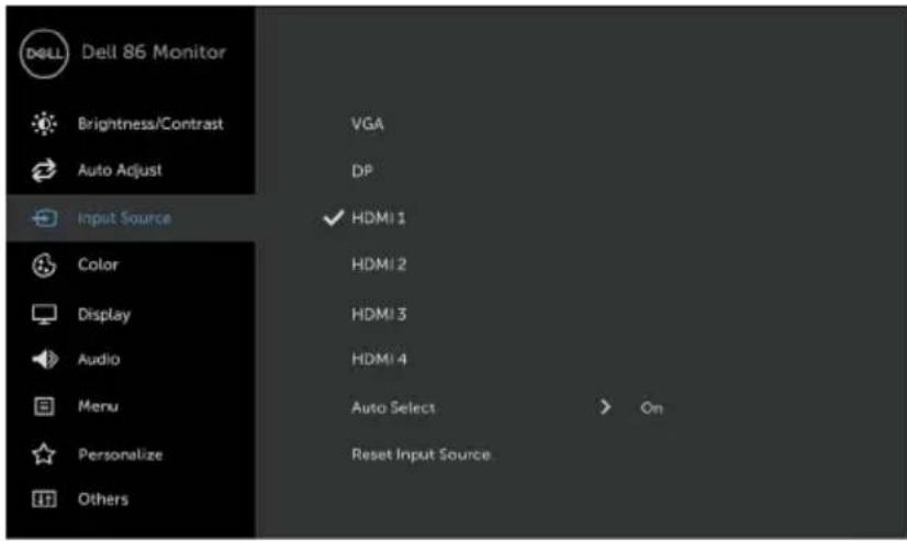
Use the Input Source menu to select between different video inputs that are be connected to your display.
text_image
Dell 86 Monitor Brightness/Contrast Auto Adjust Input Source Color Display Audio Menu Personalize Others VGA DP HDMI 1 HDMI 2 HDMI 3 HDMI 4 Auto Select Reset Input Source On
| VGA | Select VGA input when you are using the VGA connector. |
| DP Select DP input when you are using the DP (DisplayPort) connector. | |
| HDMI 1 | Select the HDMI 1 input when you are using the HDMI 1 connector. |
| HDMI 2 | Select the HDMI 2 input when you are using the HDMI 2 connector. |
| HDMI 3 | Select the HDMI 3 input when you are using the HDMI 3 connector. |
| HDMI 4 | Select the HDMI 4 input when you are using the HDMI 4 connector. |
| Auto Select | Select Auto Select, the display scans for available input sources. |
| Reset Input Source | Resets your display's Input Source settings to the factory defaults. |
Icon Menu and
Description
Submenus

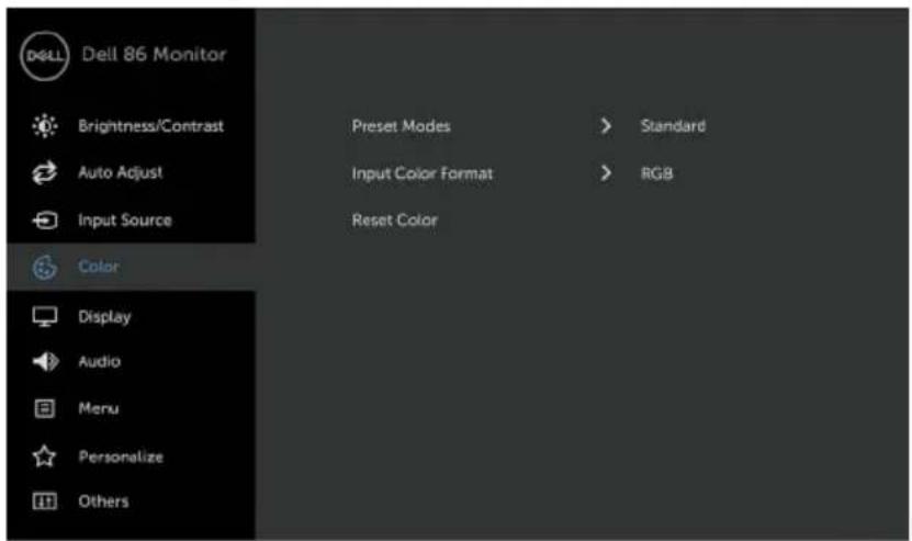
Color Use the Color menu to adjust the color setting mode.
text_image
Dell 86 Monitor Brightness/Contrast Auto Adjust Input Source Color Display Audio Menu Personalize Others Preset Modes > Standard Input Color Format > RGB Reset Color
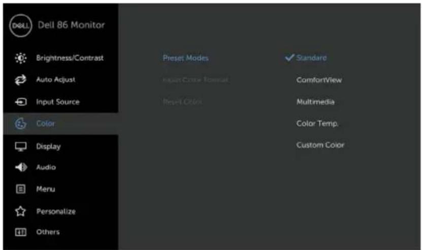
Preset Modes
When you select Preset Modes, you can choose Standard, ComfortView, Multimedia, Color Temp., or Custom Color from the list.
text_image
Dell 86 Monitor Brightness/Contrast Auto Adjust Input Source Color Display Audio Menu Personalize Others Preset Modes Standard Input Color Format ComfortView Reset Colors Multimedia Color Temp. Custom Color

- Standard: Default color settings. This is the default preset mode.

| Icon Menu and Submenus | Description |
| ComfortView: Decreases the level of blue light emitted from the screen to make viewing more comfortable for your eyes.NOTE: To reduce the risk of eye strain and neck/arm/back/shoulders pain from using the display for long periods of time, we suggest you to :Set the screen about 20 to 28 inches (50-70 cm) from your eyes.Blink frequently to moisten or rewet your eyes when working with the display.Take regular and frequent breaks for 20 minutes every two hours.Look away from your display and gaze at a distant object at 20 feet away for at least 20 seconds during the breaks.Perform stretches to relieve tension in the neck/arm/back/shoulders during the breaks.Multimedia: Ideal for multimedia applications.Color Temp.: The screen appears warmer with a red/yellow tint with slider set at 5,000K or cooler with blue tint with slider set at 10,000K.Custom Color: Allows you to manually adjust the color settings.Touch the and buttons to adjust the Red, Green, and Blue values and create your own preset color mode. | |
| Input Color Format | Allows you to set the video input mode to:RGB: Select this option if your display is connected to a computer (or DVD player) using the HDMI, DP or VGA cable.YPbPr: Select this option if your DVD player supports only YPbPr output. |
Reset Color Resets your display's color settings to the factory defaults.
Icon Menu and
Description
Submenus

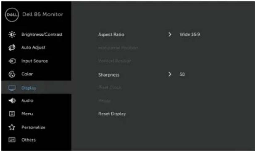
Display Use the Display menu to adjust image.
text_image
Dell 86 Monitor Brightness/Contrast Auto Adjust Input Source Color Display Audio Menu Personalize Others Aspect Ratio > Wide 16:9 Horizontal Position Vertical Position Sharpness > 50 Pixel Clock Blade Reset Display
| Aspect Ratio | Adjust the image ratio to Wide 16:9, Auto Resize,4:3, or 5:4. |
| Horizontal Position | Use 📄 to adjust the image left or right.Minimum is ‘0’ (-).Maximum is ‘100’ (+). |
| Vertical Position | Use 📄 to adjust the image up or down.Minimum is ‘0’ (-).Maximum is ‘100’ (+).NOTE: Horizontal Position and Vertical Position adjustments are only available for “VGA” input. |
| Sharpness Makes the image look sharper or softer.Use 📄 to adjust the sharpness from ‘0’ to ‘100’. | |
| Pixel Clock | The Phase and Pixel Clock adjustments allow you to adjust your display to your preference.Use the 📄 icon to adjust for best image quality.NOTE: Pixel Clock adjustments are only available for “VGA” input. |
| Phase | If satisfactory results are not obtained using the Phase adjustment, use the Pixel Clock (coarse) adjustment and then use Phase (fine) again.NOTE: Phase adjustments are only available for “VGA” input. |

Icon Menu and Submenus
Description
Reset Display Restores the display settings to factory defaults.

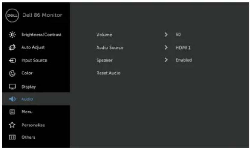
Audio
text_image
Dell 86 Monitor Brightness/Contrast Volume > 50 Auto Adjust Audio Source > HDMI 1 Input Source Speaker > Enabled Color Reset Audio Display Audio Menu Personalize Others
Volume Allows you to set the volume level of audio source.
Use 🔥 to just the volume level from '0' to '100'.
Audio Source Allows you to set the audio source to PC Audio or HDMI/DP.
Speaker Allows you to enable or disable Speaker function.
Reset Audio Select this option to restore default audio settings.

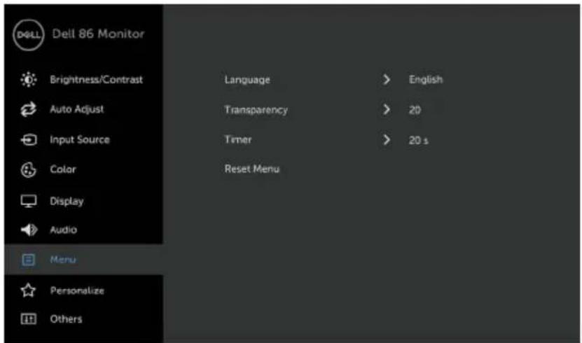
Menu Select this option to adjust the settings of the OSD, such as, the languages of the OSD, the amount of time the menu remains on screen, and so on.
text_image
Dell 86 Monitor Brightness/Contrast Auto Adjust Input Source Color Display Audio Menu Personalize Others Language > English Transparency > 20 Timer > 20 s Reset Menu

| Icon Menu and Submenus | Description |
| Language Set the OSD display to one of eight languages.(English, Spanish, French, German, Brazilian Portuguese, Russian, Simplified Chinese, or Japanese). | |
| Transparency Select this option to change the menu transparency by using ⚠ and 🎨ons (min. 0 / max. 100). | |
| Timer OSD Hold Time: Sets the time the OSD remains active after you press a button.Use the 🔊 and ic 🔑 to adjust the slider in 1-second increments, from 5 to 60 seconds. | |
| Reset Menu Restore the menu settings to factory defaults. | |
 Personalize Personalize 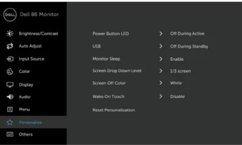 [2x35] [2x35] | |
| Power Button LED Allows you to set the state of the power light to save energy. | |
| USB Allows you to enable or disable USB function during display standby mode. | |
| NOTE: USB ON/OFF under standby mode is only available when the USB upstream cable is unplugged. This option will be greyed out when the USB upstream cable plugs in. | |
| Monitor Sleep Select Disable to turn off this feature. | |
| Screen Drop Down Level Allows you to set the Screen Drop Down level so that you can reach the top of the image.Drop Down Level Options:- 1/2 Screen- 1/3 Screen- 2/3 Screen | |

| Icon Menu and Submenus | Description |
| Screen Off Color | Allows you to set the Screen Off Color to White or black. |
| Wake On Touch | Select Enable to turn on this feature. |
| Reset Personalization | Restores shortcut keys to factory defaults. |

Other
text_image
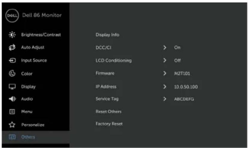
Dell 86 Monitor Brightness/Contrast Auto Adjust Input Source Color Display Audio Menu Personalize Others Display Info DCC/CI LCD Conditioning Firmware IP Address Service Tag Reset Others Factory Reset On Off M2T101 10.0.50.100 ABCDEFG
Select this option to adjust the OSD settings, such as the DDC/CI, LCD conditioning, and so on.
Display Info Displays the display's current settings.
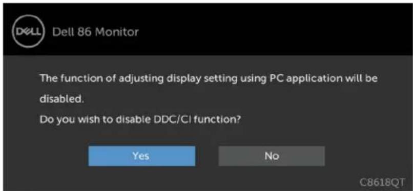
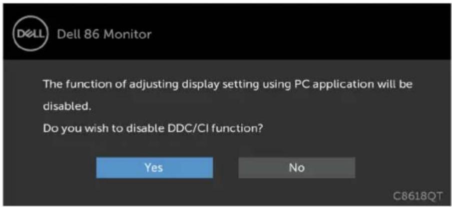
DDC/CI DDC/CI (Display Data Channel/Command Interface) allows you to adjust the display settings using software on your computer. Select Disable to turn off this feature.
Enable this feature for best user experience and optimum performance of your display.
text_image
DELL 86 Monitor The function of adjusting display setting using PC application will be disabled. Do you wish to disable DDC/CI function? Yes No C8618QT| Icon Menu and Submenus | Description |
| LCD Conditioning | Helps reduce minor cases of image retention. Depending on the degree of image retention, the program may take some time to run. Select Enable to start the process.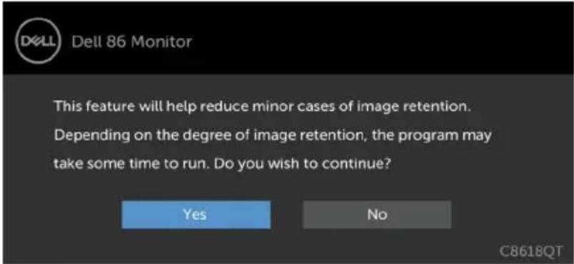 |
| Firmware Current Firmware version. | |
| IP Address Show IP Address. | |
| Service Tag Show Service Tag. | |
| Reset Others | Restores other settings, such as DDC/CI, to factory defaults. |
| Factory Reset | Restores all OSD settings to the factory defaults. |

NOTE: This display has a built-in feature to automatically calibrate the brightness to compensate for LED aging.
OSD Warning Messages
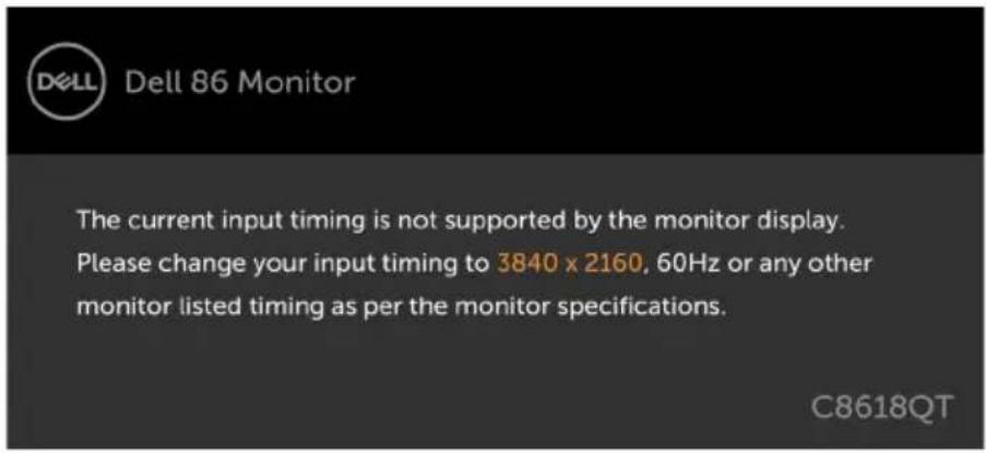
When the display does not support a particular resolution mode, you can see the following message:
text_image
DELL Dell 86 Monitor The current input timing is not supported by the monitor display. Please change your input timing to 3840 x 2160, 60Hz or any other monitor listed timing as per the monitor specifications. C8618QTThis means that the display cannot synchronize with the signal that it is receiving from the computer. See Display Specifications for the Horizontal and Vertical frequency ranges addressable by this display. Recommended mode is 3840 x 2160.
You can see the following message before the DDC/CI function is disabled:
text_image
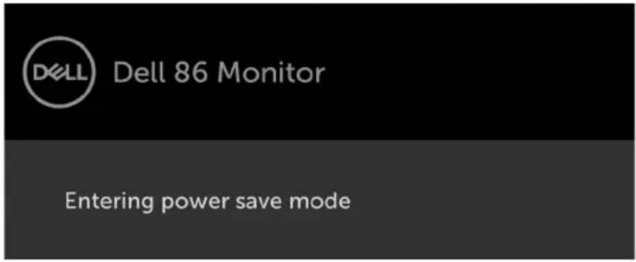
DELL Dell 86 Monitor The function of adjusting display setting using PC application will be disabled. Do you wish to disable DDC/CI function? Yes No C8618QTWhen the display enters the Power Save mode, the following message appears:
text_image
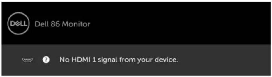
DELL Dell 86 Monitor Entering power save modeIf you press any button other than the power button, the following messages will appear depending on the selected input:
text_image
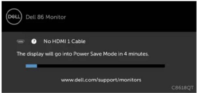
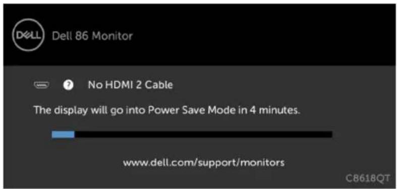
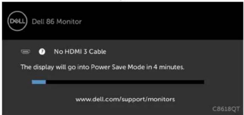
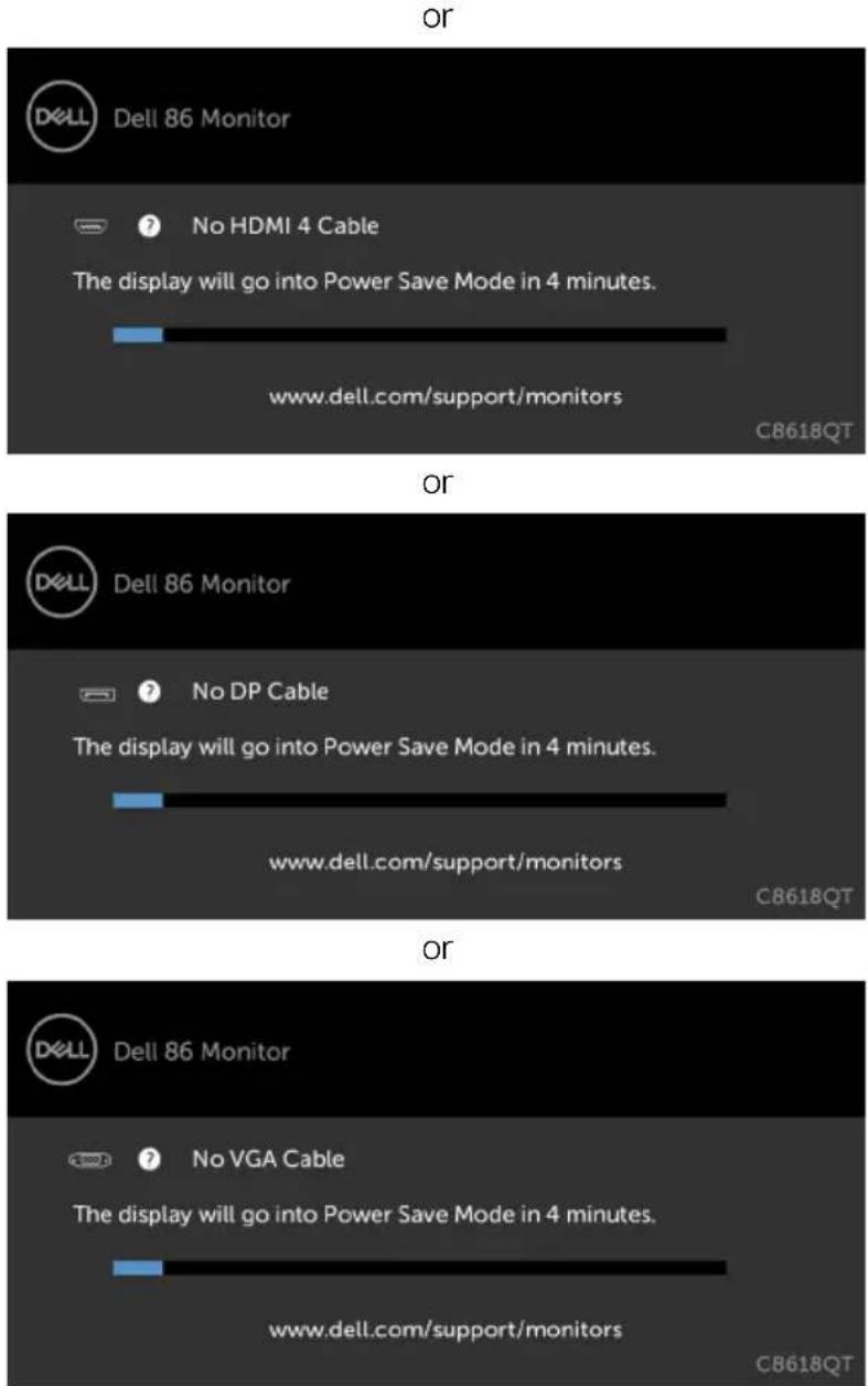
DELL Dell 86 Monitor ? No HDMI 1 signal from your device.If either HDMI 1, HDMI 2, HDMI 3, HDMI 4, DP or VGA input is selected and the corresponding cable is not connected, a floating dialog box as shown below appears.
text_image
Dell 86 Monitor No HDMI 1 Cable The display will go into Power Save Mode in 4 minutes. www.dell.com/support/monitors CB618QTor
text_image
Dell 86 Monitor No HDMI 2 Cable The display will go into Power Save Mode in 4 minutes. www.dell.com/support/monitors CB618QTor
text_image
DELL Dell 86 Monitor No HDMI 3 Cable The display will go into Power Save Mode in 4 minutes. www.dell.com/support/monitors C8618QT
text_image
OR Dell 86 Monitor No HDMI 4 Cable The display will go into Power Save Mode in 4 minutes. www.dell.com/support/monitors C8618QT OR Dell 86 Monitor No DP Cable The display will go into Power Save Mode in 4 minutes. www.dell.com/support/monitors C8618QT OR Dell 86 Monitor No VGA Cable The display will go into Power Save Mode in 4 minutes. www.dell.com/support/monitors C8618QTSee Troubleshooting for more information.
Dell Web Management for Displays
Before accessing the Dell Display Web Management feature, ensure the Ethernet is working normally.
text_image
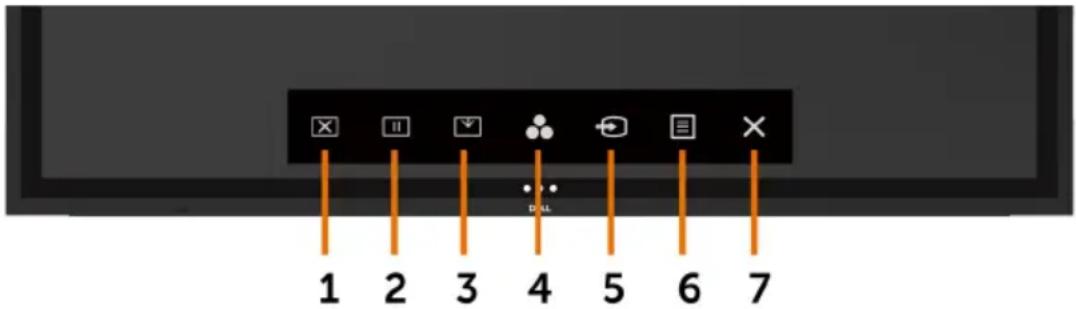
1 2 3 4 5 6 7- Ethernet Enable
Touch and hold the touch key 5 on the front panel for 4 seconds to turn on, A network icon appears and is shown on the center for 4 seconds.
- Ethernet Disable
Touch and hold the touch key 5 on the front panel for 4 seconds to turn off, A network icon appears and is shown on the center for 4 seconds.
To access the Dell Display Web Management tool you need to set the IP Addresses for your computer and the display.
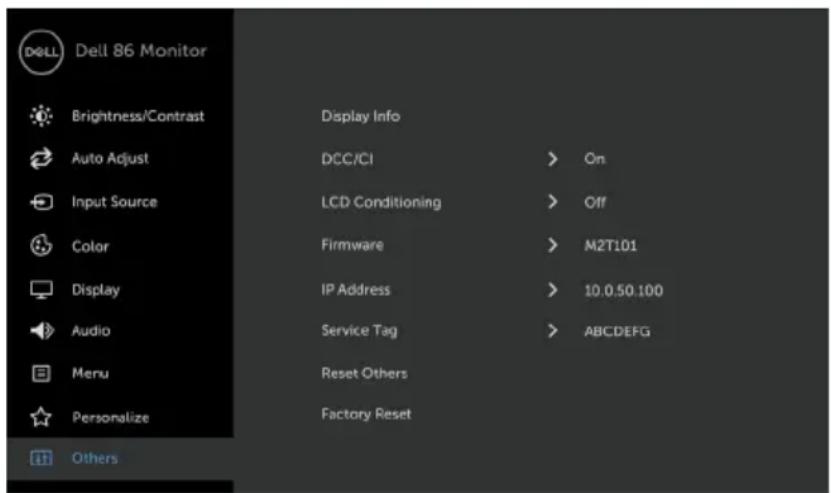
- Press the Menu key on the remote control to display the IP Address of the display, or by navigating to OSD Menu > Others. By default, the IP Address is 10.0.50.100
text_image
Dell 86 Monitor Brightness/Contrast Auto Adjust Input Source Color Display Audio Menu Personalize Others Display Info DCC/CI LCD Conditioning Firmware IP Address Service Tag Reset Others Factory Reset On Off M2T101 10.0.50.100 ABCDEFG

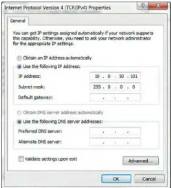
- In the computer's IP Properties tab, specify an IP Address by selecting Use the following IP Address and enter the following values: For IP Address: 10.0.50.101 and for Subnet Mask: 255.0.0.0 (leave all other entries as blanks).
text_image
Internet Protocol Version 4 (TCP/IPv4) Properties General You can get IP settings assigned automatically if your network supports this capability. Otherwise, you need to ask your network administrator for the appropriate IP settings. Obtain an IP Address automatically Use the following IP Address: IP Address: 10 . 0 . 50 . 101 Subnet mask: 255 . 0 . 0 . 0 Default gateway: . Obtain DNS server address automatically Use the following DNS server addresses: Preferred DNS server: . Alternate DNS server: . Validate settings upon exit Advanced... OK Cancel- The IP Address configuration would now look like this:
natural_image
Laptop computer with blue screen and silver bezel (no visible text or symbols)Configure notebook IP Address to 10.0.50.101
natural_image
Blank dark image with no visible content, text, or symbolsMonitor IP Address 10.0.50.100
To access and use the web management tool, follow these steps:
- Open a web browser and type the display's IP Address (10.0.50.100) in the address bar.
- The log-in page opens. Enter the Administrator Password to continue.
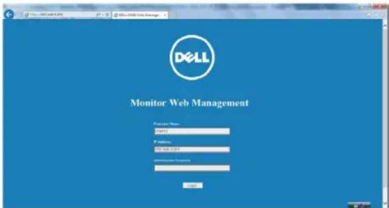
text_image
DOLL Monitor Web Management Analysis Name: SPART2 P Address: XP Sub-2.017 Microsoft Access Login
3. The Home page opens:
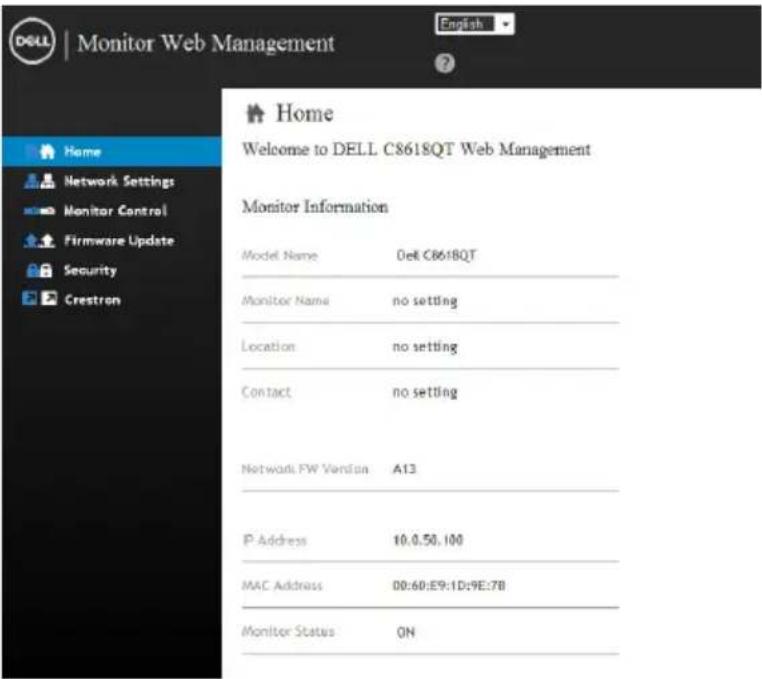
text_image
DELL | Monitor Web Management Home Welcome to DELL C8618QT Web Management Monitor Information Model Name Dell C8618QT Monitor Name=no setting Location=no setting Contact=no setting Network FW Version A13 IP Address 10.0.50.100 MAC Address 00:60:E9:1D:9E:7B Monitor Status ON4. Click Network Settings tab to see the network settings.
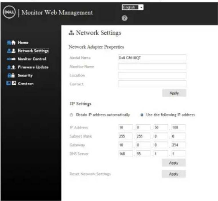
text_image
DOLL | Monitor Web Management English ? Network Settings Network Adapter Properties Model Name: Dull C8618QT Monitor Name: Location: Contact: Apply IP Settings Obtain IP address automatically Use the following IP address IP Address 10 0 50 100 Subnet Mask 255 255 0 0 Gateway 10 0 0 254 DNS Server 168 95 1 1 Apply Reset Network Settings Apply- Click Display Control to see the display's status.
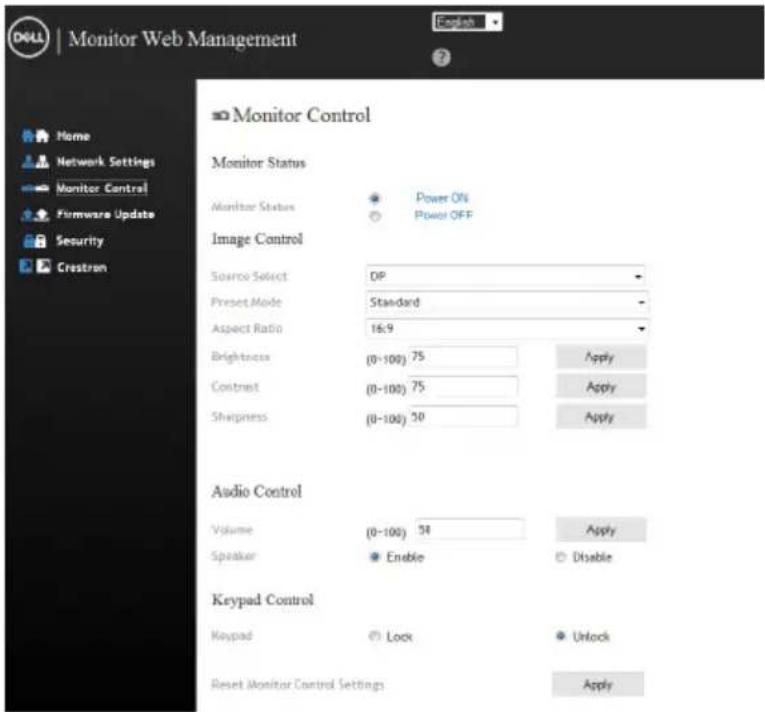
text_image
Monitor Web Management Home Network Settings Monitor Control Firmware Update Security Crestzen Monitor Control Monitor Status Monitor Status Power ON Power OFF Image Control Source Select DP Preset Mode Standard Aspect Ratio 16.9 Brightness (0-100) 75 Apply Contrast (0-100) 75 Apply Sharpness (0-100) 30 Apply Audio Control Volume (0-100) 54 Apply Speaker Enable Disable Keypad Control Keypad Lock Unlock Reset Monitor Control Settings Apply- Update Firmware. You can download the latest drivers from the Dell Support website at www.dell.com/support.
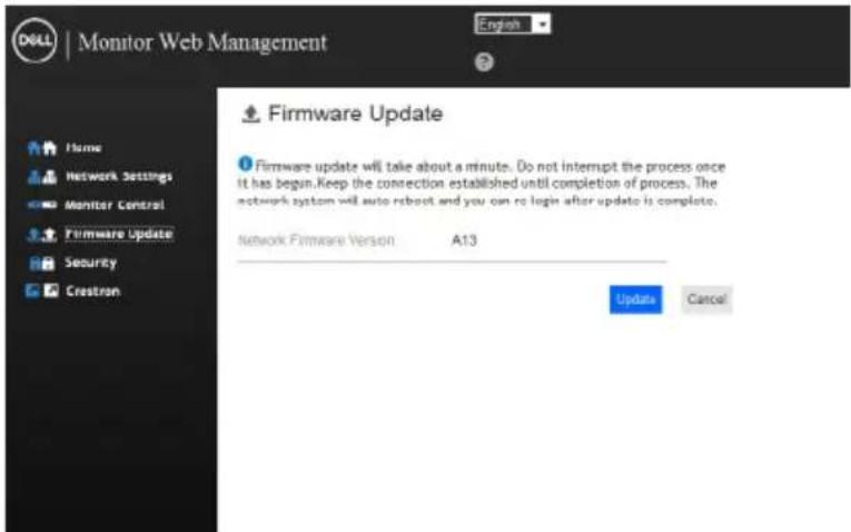
text_image
DOLL | Monitor Web Management Home Network Settings Monitor Control Firmware Update Security Crestron English Firmware Update Firmware update will take about a minute. Do not interrupt the process once it has begun.Keep the connection established until completion of process. The network system will auto reboot and you can go to login after update is complete. Network Firmware Version A13 Update Cancel- Upgrade firmware page and wait for 30 seconds.
Upgrade Firmware
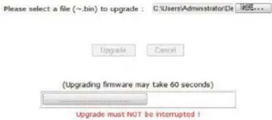
text_image
Please select a file (~.bin) to upgrade : C:\Users\Administrator\De Upgrade Cancel (Upgrading firmware may take 60 seconds) Upgrade must NOT be interrupted !
- Finished. Click on button to proceed after 8 seconds.
Please wait. Click on button to proceed after 8 seconds.
Waiting(6)
- Click Security to set a password.
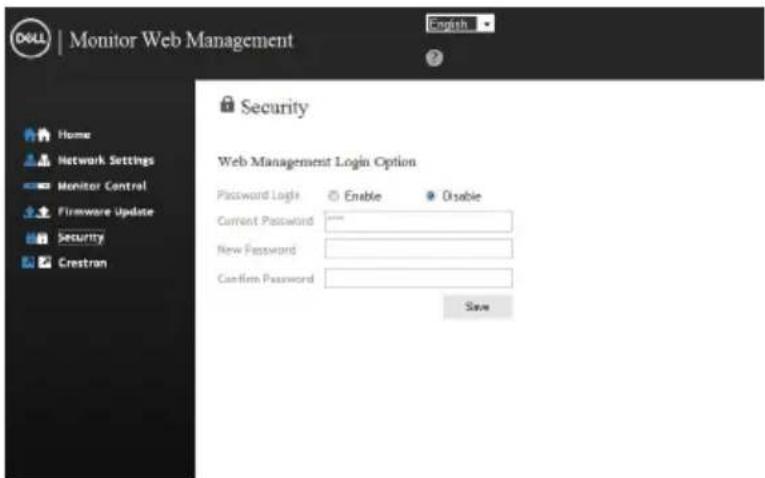
text_image
DOLL | Monitor Web Management Home Network Settings Monitor Control Firmware Update Security Crestran Security Web Management Login Option Password Login Enable Disable Current Password ****** New Password : Confirm Password : Save- Click Crestron to control interface.
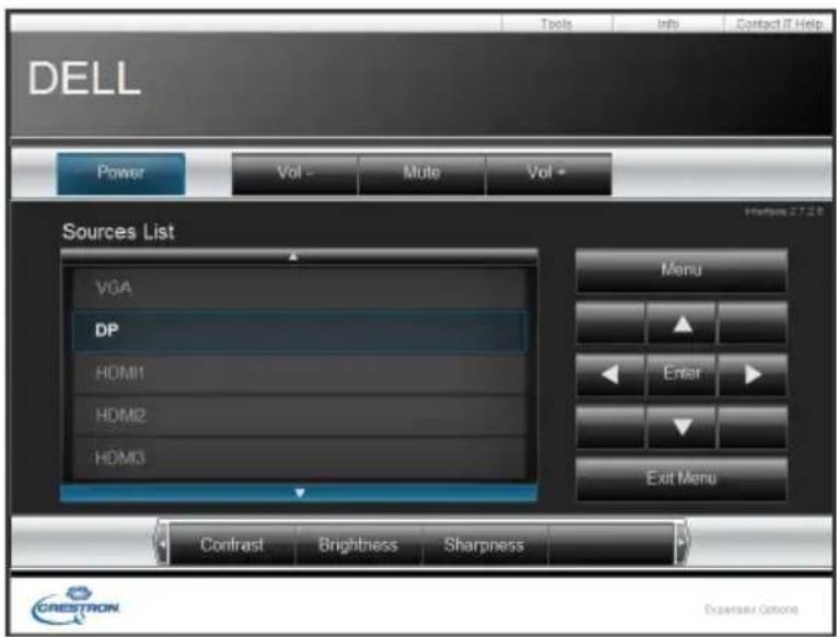
text_image
DELL Tools Info Contact IT Help Power Vol - Mute Vol - Sources List VGA DP HDMI1 HDMI2 HDMI3 Menu Enter Exit Menu Contrast Brightness Sharpness CREDSTON Excisev Options
WARNING: Before you begin any of the procedures in this section, follow the Safety Instructions.
Self-Test
Your display provides a self-test feature that allows you to check whether your display is functioning properly. If your display and computer are properly connected but the display screen remains dark, run the display self-test by performing the following steps:
- Turn off both your computer and the display.
- Unplug the video cable from the back of the computer. To ensure proper Self-Test operation, remove all digital and the analog cables from the back of computer.
- Turn on the display.
The floating dialog box should appear on-screen (against a black background), if the display cannot sense a video signal and is working correctly. While in self-test mode, the power LED remains white. Also, depending upon the selected input, one of the dialogs shown below will continuously scroll through the screen.
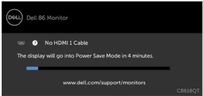
text_image
Dell 86 Monitor No HDMI 1 Cable The display will go into Power Save Mode in 4 minutes. www.dell.com/support/monitors CB618QTor
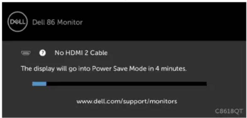
text_image
Dell 86 Monitor No HDMI 2 Cable The display will go into Power Save Mode in 4 minutes. www.dell.com/support/monitors CB618QT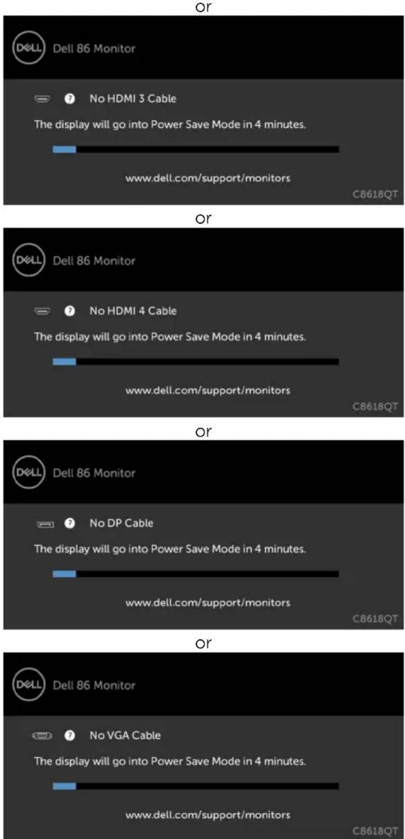
text_image
Or Dell 86 Monitor No HDMI 3 Cable The display will go into Power Save Mode in 4 minutes. www.dell.com/support/monitors C8618QT Or Dell 86 Monitor No HDMI 4 Cable The display will go into Power Save Mode in 4 minutes. www.dell.com/support/monitors C8618QT Or Dell 86 Monitor No DP Cable The display will go into Power Save Mode in 4 minutes. www.dell.com/support/monitors C8618QT Or Dell 86 Monitor No VGA Cable The display will go into Power Save Mode in 4 minutes. www.dell.com/support/monitors C8618QT- This box also appears during normal system operation, if the video cable becomes disconnected or damaged.
- Turn off your display and reconnect the video cable; then turn on both your computer and the display.
If your display screen remains blank after you use the previous procedure, check your video controller and computer, because your display is functioning properly.
Built-in Diagnostics
Your display has a built-in diagnostic tool that helps you determine if the screen abnormality you are experiencing is an inherent problem with your display, or with your computer and video card.
text_image
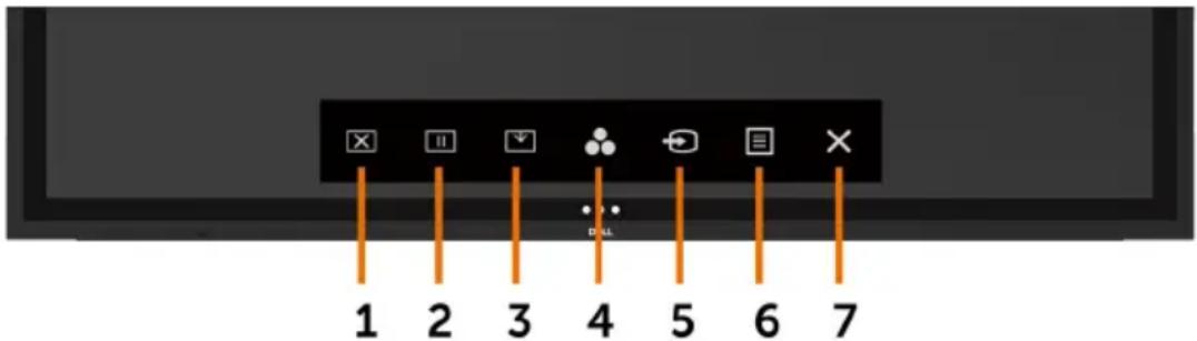
1 2 3 4 5 6 7To run the built-in diagnostics:
- Make sure that the screen is clean (no dust particles on the surface of the screen).
- Touch and hold ✗ or 5 seconds in lock Select Option. Touch the self-inspection icon □ gray screen appears.
- Carefully inspect the screen for abnormalities.
- Touch the front panel again. The color of the screen changes to red.
- Inspect the display for any abnormalities.
- Repeat steps 4 and 5 to inspect the display in green, blue, black, white, and text screens.
The test is complete when the text screen appears. To exit, touch panel again.
If you do not detect any screen abnormalities upon using the built-in diagnostic tool, the display is functioning properly. Check the video card and computer.
Common Problems
The following table contains general information about common display problems you might encounter and the possible solutions:

NOTE: Auto Adjust function is applicable to VGA input only.
| Common Symptoms | What You Experience | Possible Solutions |
| No Video/Power LED off | No picture · Ensure | that the video cable connecting the display and the computer is properly connected and secure.· Verify that the power outlet is functioning properly using any other electrical equipment.· Ensure that the power button is depressed fully.· Ensure that the correct input source is selected in the Input Source menu. |
| No Video/Power LED on | No picture or no brightness | · Increase brightness & contrast controls via OSD.· Perform display self-test feature check.· Check for bent or broken pins in the video cable connector.· Run the built-in diagnostics.· Ensure that the correct input source is selected in the Input Source menu. |
| Poor Focus Picture is fuzzy, blurry, or ghosting | · Perform Auto Adjust via OSD.· Adjust the Phase and Pixel Clock controls via OSD.· Eliminate video extension cables.· Reset the display to factory settings.· Change the video resolution to the correct aspect ratio. | |
| Shaky/Jittery Video Wavy picture or fine movement | · Perform Auto Adjust via OSD.· Adjust the Phase and Pixel Clock controls via OSD.· Reset the display to factory settings.· Check environmental factors.· Relocate the display and test in another room. | |
| Missing Pixels LCD screen has spots | · Cycle power on-off.· Pixel that is permanently off is a natural defect that can occur in LCD technology.· For more information on Dell Display Quality and Pixel Policy, see Dell Support site at: http://www.dell.com/support/monitors. | |
| Stuck-on Pixels LCD screen has bright spots | · Cycle power On-Off.· Pixel that is permanently off is a natural defect that can occur in LCD technology.· For more information on Dell Display Quality and PixelPolicy, see Dell Support site at: http://www.dell.com/support/monitors. | |

| Common Symptoms | What You Experience | Possible Solutions |
| Brightness Problems | Picture too dim or too bright | Reset the display to factory settings.Auto Adjust via OSD.Adjust brightness & contrast controls via OSD. |
| Audio problem | No Audio | Check PC setting if the playback is correctly selected.Checking other video cables.Ensure that the Speaker is enabled via OSD |
| Geometric Distortion | Screen not centered correctly | Reset the display to factory settings.Auto Adjust via OSD.Adjust horizontal & vertical controls via OSD. |
| Horizontal/Vertical Lines | Screen has one or more lines | Reset the display to factory settings.Perform Auto Adjust via OSD.Adjust Phase and Pixel Clock controls via OSD.Perform display self-test feature check and determine if these lines are also in self-test mode.Check for bent or broken pins in the video cable connector.Run the built-in diagnostics. |
| Synchronization Problems | Screen is scrambled or appears torn | Reset the display to factory settings.Perform Auto Adjust via OSD.Adjust Phase and Pixel Clock controls via OSD.Perform display self-test feature check to determine if the scrambled screen appears in self-test mode.Check for bent or broken pins in the video cable connector.Restart the computer in safe mode. |
| Safety Related Issues | Visible signs of smoke or sparks | Do not perform any troubleshooting steps.Contact Dell immediately. |
| Intermittent Problems | Display malfunctions on & off | Ensure that the video cable connecting the display to the computer is connected properly and is secure.Reset the display to factory settings.Perform display self-test feature check to determine if the intermittent problem occurs in self-test mode. |
| Missing Color Picture missing color | Perform display self-test.Ensure that the video cable connecting the display to the computer is connected properly and is secure.Check for bent or broken pins in the video cable connector. | |
| Wrong Color Picture color not good | Change the settings of the Preset Modes in the Color menu OSD depending on the application.Adjust R/G/B value under Custom. Color in Color menu OSD.Change the Input Color Format to PC RGB or YPbPr in the Color menu OSD.Run the built-in diagnostics. | |
| Image retention from a static image left on the display for a long period of time | Faint shadow from the static image displayed appears on the screen | · Use the Power Management feature to turn off the display at all times when not in use (for more information, seePower Management Modes). · Alternatively, use a dynamically changing screensaver. |
| Touchscreen non-responsive | Display cannot wake on touch | · Ensure Wake On Touch is enabled via OSD. Wake On Touch is default off. |
Product Specific Problems
| Specific Symptoms | What You Experience | Possible Solutions |
| Screen image is too small | Image is centered on screen, but does not fill entire viewing area | · Check the Aspect Ratio setting in the Display menu OSD.· Reset the display to factory settings. |
| Cannot adjust the display with touch OSD | OSD does not appear on the screen | · Turn off the display, unplug the display power cable, plug it back, and then turn on the display.· Check whether the OSD menu is locked. If yes, touch icon for 4 seconds to unlock . |
| No Input Signal when user controls are pressed | No picture, the LED light is white | · Check the signal source. Ensure the computer is not in the power saving mode by moving the mouse or pressing any key on the keyboard.· Check whether the signal cable is plugged in properly. Re-plug the signal cable if necessary.· Reset the computer or video player. |
| The picture does not fill the entire screen | The picture cannot fill the height or width of the screen | · Due to different video formats (aspect ratio) of DVDs, the display may display in full screen.· Run the built-in diagnostics. |
Touchscreen Problems
| Specific Symptoms | What You Experience | Possible Solutions |
| Windows 7 | Cursor does not accurately follow your finger when you touch the screen | • Install touch driver for Windows 7, see Dell Support site at: http://www.dell.com/support/monitors. |
Universal Serial Bus (USB) Specific Problems
| Specific Symptoms | What You Experience | Possible Solutions |
| USB interface is not working | USB peripherals are not working | ·Check that your display is turned ON.·Reconnect the upstream cable to your computer.·Reconnect the USB peripherals (downstream connector).·Switch off and then turn on the display again.·Reboot the computer.·Some USB devices like external portable HDD require higher electric current; connect the device directly to the computer system. |
| SuperSpeed USB 3.0 interface is slow. | SuperSpeed USB 3.0 peripherals working slowly or not working at all | ·Check that your computer is USB 3.0-capable.·Some computers have USB 3.0, USB 2.0, and USB 1.1 ports. Ensure that the correct USB port is used.·Reconnect the upstream cable to your computer.·Reconnect the USB peripherals (downstream connector).·Reboot the computer. |
| Wireless USB peripherals stop working when a USB 3.0 device is plugged in | Wireless USB peripherals responding slowly or only working as the distance between itself and its receiver decreases | ·Increase the distance between the USB 3.0 peripherals and the wireless USB receiver.·Position your wireless USB receiver as close as possible to the wireless USB peripherals.·Use a USB-extender cable to position the wireless USB receiver as far away as possible from the USB 3.0 port. |
| USB is not working | No USB functionalities | Refer to input source and USB pairing table |
Ethernet Problems
| Specific Symptoms | What You Experience | Possible Solutions |
| Ethernet not working | Dell Web Management for Displays Webpage control is not working | · Ensure that the Network cable connecting the Display is properly secured.· Touch the icon 5 on the screen for 4 seconds to turn on, A network icon appears and is shown on the center for 4 seconds.· Touch the icon 5 on the front panel for 4 seconds to turn off, A network icon appears and is shown on the center for 4 seconds.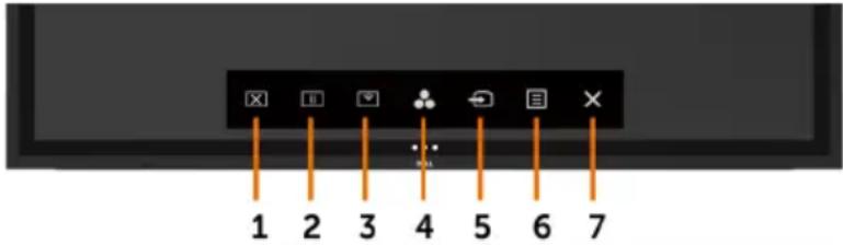 |
Safety Instructions
For displays with glossy bezels the user should consider the placement of the display as the bezel may cause disturbing reflections from surrounding light and bright surfaces.

WARNING: Use of controls, adjustments, or procedures other than those specified in this documentation may result in exposure to shock, electrical hazards, and/or mechanical hazards.
For information on safety instructions, see the Safety, Environmental, and Regulatory Information (SERI).
FCC Notices (U.S. only) and Other Regulatory Information
For FCC notices and other regulatory information, see the regulatory compliance website located at www.dell.com/regulatory_compliance.
Contacting Dell

NOTE: If you do not have an active Internet connection, you can find contact information on your purchase invoice, packing slip, bill, or Dell product catalog.
Dell provides several online and telephone-based support and service options. Availability varies by country and product, and some services may not be available in your area.
To get online Display support content:
See www.dell.com/support/monitors.
To contact Dell for sales, technical support, or customer service issues:
- Go to www.dell.com/support.
- Verify your country or region in the Choose A Country/Region drop-down menu at the top-left corner of the page.
- Click Contact Us next to the country dropdown.
- Select the appropriate service or support link based on your need.
- Choose the method of contacting Dell that is convenient for you.
Setting Up Your Display
Setting Display Resolution to 3840 x 2160 (maximum)
For best performance, set the display resolution to 3840 x 2160 pixels by performing the following steps:
In Windows 7, Windows 8 or Windows 8.1:
- For Windows 8 or Windows 8.1 only, select the Desktop tile to switch to classic desktop.
- Right-click on the desktop and click Screen Resolution.
- Click the Dropdown list of the Screen Resolution and select 3840 x 2160.
- Click OK.
In Windows 10:
- Right-click on the desktop and click Display Settings.
- Click Advanced display settings.
- Click the dropdown list of Resolution and select 3840 x 2160.
- Click Apply.
If you do not see the recommended resolution as an option, you may need to update your graphics driver. Please choose the scenario below that best describes the computer system you are using, and follow the given steps.
Dell computer
- Go to www.dell.com/support, enter your service tag, and download the latest driver for your graphics card.
- After installing the drivers for your graphics adapter, attempt to set the resolution to 3840 x 2160 again.

NOTE: If you are unable to set the resolution to 3840 × 2160 , please contact Dell to inquire about a graphics adapter that supports these resolutions.

Non-Dell computer
In Windows 7, Windows 8 or Windows 8.1:
- For Windows 8 or Windows 8.1 only, select the Desktop tile to switch to classic desktop.
- Right-click on the desktop and click Personalization.
- Click Change Display Settings.
- Click Advanced Settings.
- Identify your graphics controller supplier from the description at the top of the window (e.g. NVIDIA, ATI, Intel etc.).
- Refer to the graphic card provider website for updated driver (for example, http://www.ATI.com or http://www.NVIDIA.com).
- After installing the drivers for your graphics adapter, attempt to set the resolution to 3840 x 2160 again.
In Windows 10:
- Right-click on the desktop and click Display Settings.
- Click Advanced display settings.
- Click Display adapter properties.
- Identify your graphics controller supplier from the description at the top of the window (e.g. NVIDIA, ATI, Intel etc.).
- Refer to the graphic card provider website for updated driver (for example, http://www.ATI.com or http://www.NVIDIA.com).
- After installing the drivers for your graphics adapter, attempt to set the resolution to 3840 x 2160 again.

NOTE: If you are unable to set the recommended resolution, please contact the manufacturer of your computer or consider purchasing a graphics adapter that supports the video resolution.
Maintenance Guidelines
Cleaning Your Display

WARNING: Before cleaning the display, unplug the display power cable from the electrical outlet.

CAUTION: Read and follow the Safety Instructions before cleaning the display.
For best practices, follow these instructions in the list below while unpacking, cleaning, or handling your display:
- To clean your anti-static screen, lightly dampen a soft, clean cloth with water. If possible, use a special screen-cleaning tissue or solution suitable for the anti-static coating. Do not use benzene, thinner, ammonia, abrasive cleaners, or compressed air.
- Use a lightly-dampened, soft cloth to clean the display. Avoid using detergent of any kind as some detergents leave a milky film on the display.
• If you notice white powder when you unpack your display, wipe it off with a cloth. - Handle your display with care as a darker-colored display may get scratched and show white scuff marks more than a lighter-colored display.
- To help maintain the best image quality on your display, use a dynamically changing screen saver and turn off your display when not in use.