
AZWG10200 - Power inverter ABUS - Free user manual and instructions
Find the device manual for free AZWG10200 ABUS in PDF.


| Product Type | PSTN/IP Converter (IP/GPRS Transmission Device) |
| Manufacturer | ABUS Security-Center GmbH & Co. KG |
| Model | AZWG10200 |
| Dimensions (LxWxH) | 150 x 190 x 64 mm |
| Weight | 0.338 kg |
| Operating Temperature | -25°C to +60°C |
| Power Supply Voltage | 10-28V DC |
| Power Consumption (Idle) | 70 mA at 12V DC |
| Power Consumption (LAN) | 85 mA at 12V DC |
| Power Consumption (GPRS) | 170 mA at 12V DC |
| Communication Interfaces | 10/100 Mb Ethernet (RJ45), USB mini 5-pin, GSM/GPRS (2G) with SMA antenna connector |
| Supervised Alarm Lines | 8 (analogue, configurable NO/NC, 10K or 8K2/15K monitoring) |
| Digital Inputs (AUX) | 2 (high/low, for tamper or other) |
| Relay Outputs | 2 (OUT1: transmission error; OUT2: fault) |
| Supported Protocols | VdS 2465, Contact ID DC-09, SIA DC-09 (TCP/UDP) |
| Encryption | AES 128, AES 192, AES 256 (hex keys) |
| SIM Card | GPRS (2G), multi-roaming, ~1 MB/month for redundant use |
| Programming Software | ParamIt+ (via USB or remote access) |
| LED Indicators | 4 LEDs: green (power), red (transmission), yellow (converter and fault) |
| Enclosure Material | Plastic |
| Certifications | CE, EN 50136-1:2012 |
| Warranty | 2 years (material/manufacturing defects) |
| Intended Use | Convert analogue alarm system notifications to IP transmission for monitoring stations |
| Redundant Transmission | Supports single (SP) and dual-path (DP) transmission methods |
Frequently Asked Questions - AZWG10200 ABUS
User questions about AZWG10200 ABUS
0 question about this device. Answer the ones you know or ask your own.
Ask a new question about this device
Download the instructions for your Power inverter in PDF format for free! Find your manual AZWG10200 - ABUS and take your electronic device back in hand. On this page are published all the documents necessary for the use of your device. AZWG10200 by ABUS.
USER MANUAL AZWG10200 ABUS
natural_image
Exterior view of a white electronic device labeled 'ABUS' with control buttons (no readable text beyond branding)Preface
Dear Customer,
Thank you for purchasing this PSTN/IP converter. This device is built with state-of-the-art technology and complies with current domestic and European regulations. Conformity has been verified, and the CE Declaration of Conformity is available from the manufacturer on request (www.abus-sc.com).
To guarantee safe operation, it is essential that you observe these installation instructions.
We want to provide you only with devices that incorporate state-of-the-art technology, which is why we reserve the right to make technical modifications.
We also reserve the right to make changes to this manual without prior notice.
If you have further questions, please contact your specialist dealer.
Safety information
To avoid the risk of electric shock, never open the device during operation.
No part of the product may be changed or modified in any way; otherwise the device warranty will be invalidated.
The dialler may only be used within the specified temperature and protection class range. Using the device outside of the prescribed ranges leads to faster wear and tear and premature failure. All required information on this can be found in the technical data at the back of these instructions.
Do not expose the equipment to significant physical stress (knocks, vibrations, etc.) Incorrect handling and poor transport conditions may damage the device.
Contents
Preface....2
Safety information.... 2
Contents 3
Introduction 5
Information on user manual 5
Intended use....5
Limitation of liability 5
Safety information....6
Explanation of symbols....6
Packaging....6
General information....7
Power supply 7
Hardware modules 7
IP Ethernet (LAN) 7
IP/GPRS (GSM) 7
A/B converter....7
Alarm transmission....7
EN-compliant transmission....7
Redundant transmission....9
Installation and connection 9
Installation....10
Motherboard connections....11
Signal lines....12
Outputs....12
USB....12
Converter connection (POTS)....12
SIM card....12
LED displays....13
Programming with Paramlt+....13
Connecting the AZWG10200-PSTN/IP CONVERTER....15
AZWG10200-PSTN/IP CONVERTER password....17
Loading a configuration ....17
Importing a configuration from the AZWG10200-PSTN/IP CONVERTER....18
Saving a configuration on the PC/laptop....18
Saving a configuration on the AZWG10200-PSTN/IP CONVERTER....19
Changing a configuration....19
'Modules' tab ....20
'Transmission' tab....22
'Encryption' tab 24
'Notifications' tab....24
Alarm lines (eight monitored analogue inputs)....25
AUX lines (two digital inputs, high/low)....26
Test notifications (test and poll notifications)....27
AZWG10200-PSTN/IP CONVERTER system....28
Outputs....29
Diagnosis....30
Diagnosis > Modules ....31
GSM....32
Clock....32
Ethernet/LAN....32
Converter analogue port 33
Diagnosis > Alarm lines 33
Diagnosis > Outputs ....34
Diagnosis > System....35
Upgrade....37
Technical data 38
Warranty....39
Disposal 39
Declaration of conformity 39
Notes 40
Introduction
Information on user manual
Dear Customer,
Thank you for purchasing this product. This device is built with state-of-the-art technology.
These instructions contain important installation and operation information. Follow the directions and instructions in this manual to ensure safe operation. Store this manual in a safe place for future reference. This manual constitutes part of the device. If you pass the device on to third parties, please remember to include this manual.
Intended use
Only use the device for the purpose for which it was built and designed. Any other use is considered unintended.
This product complies with current domestic and European regulations. Conformity has been proven, and all related certifications are available from the manufacturer on request.
To ensure this condition is maintained and that safe operation is guaranteed, it is your obligation to observe this user manual. If you have any questions, please contact your specialist dealer. Further general information and information on product support can be found at www.abus.com on the general page or for dealers and installers, in the Partner portal.
Limitation of liability
Everything possible has been done to ensure that the content of these instructions is correct. However, neither the author nor ABUS Security-Center GmbH & Co. KG can be held liable for loss or damage caused by incorrect or improper installation and operation or failure to observe the safety instructions and warnings. No liability can be accepted for resulting damage. No part of the product may be changed or modified in any way. If you do not follow these instructions, your warranty claim becomes invalid.
Subject to technical modifications.
© ABUS Security-Center GmbH & Co. KG, 07/2016
Safety information
Explanation of symbols
The following symbols are used in this manual and on the device:
| Symbol | Signal word | Meaning |
 | Danger | Indicates a risk of injury or health hazards. |
 | Danger | Indicates a risk of injury or health hazards caused by electrical voltage. |
 | Important | Indicates possible damage to the device/accessories. |
 | Note | Indicates important information. |
 | The EU Directive WEEE 2012/19/EC governs the proper recovery, treatment and recycling of used electronic devices. This symbol means that, in the interest of environmental protection, the device must be disposed of separately from household or industrial waste at the end of its lifespan in accordance with applicable local legal guidelines. Used devices can be disposed of at official recycling centres in your country. Obey local regulations when disposing of material. Further details on returns (also for non-EU countries) can be obtained from your local authority. Separate collection and recycling conserve natural resources and ensure that all the provisions for protecting health and the environment are observed when recycling the product. |
Packaging
Danger
Keep packaging material and small parts away from children. There is a risk of suffocation.
Remove all packaging material before using the device.
General information
The AZWG10200-PSTN/IP converter is an IP/GPRS transmission device with two transmission paths. The transmission device has an LAV interface that is suitable for open and closed networks and a GPRS module for transmitting to the GSM network. Depending on the version, the notifications can be imported from the analogue alarm system either via the signal lines or via the converter.
Power supply
The AZWG10200-PSTN/IP CONVERTER is suitable for supply voltages from 10 to 28 V DC. It uses 70 mA when idle at 12 V DC, 85 mA when communicating via LAN and 170 mA when communicating via GPRS.
Hardware modules
IP Ethernet (LAN)
The RJ45 Ethernet port on the AZWG10200-PSTN/IP CONVERTER supports speeds of both 10 Mb/s and 100 Mb/s. The CONVERTER adapts to the network, with 10 Mb the preferred speed because less power is consumed. Transmissions can be sent in TCP and UDP.
IP/GPRS (GSM)
The GPRS module can send IP transmission in TCP and UDP. The registration on the network, the signal strength and IP availability are constantly checked. The status can be reported to the monitoring station via Ethernet. The ICCID number of the SIM card can be sent to the monitoring stations with each test notification, so the card can always be tracked. The antenna can be connected via an integrated SMA connector.
A/B converter
The AZWG10200-PSTN/IP CONVERTER is equipped with an A/B converter for analogue SIA, Contact ID and Telim alarm systems in order to link them easily to the modern IP networks and monitoring stations. The CONVERTER reads the alarm notifications with Telim, Contact ID or SIA, including text, from the alarm system, saves them, converts them according to the DC-09 IP protocol and then checks and sends them to the monitoring station. The analogue Telim protocol can be converted to VdS 2465 IP and SIA DC-09. All other protocols are converted from analogue to the same digital protocol, i.e. SIA analogue is converted to the digital SIA DC-09 protocol and CID analogue to the digital CID DC-09 protocol.
Alarm transmission
The AZWG10200-PSTN/IP CONVERTER sends the notifications in VdS 2465, Contact ID DC-09 and SIA DC-09 protocols as needed. VdS 2465 and SIA DC-09 also support text. The DC-09 protocol is an open, standardised protocol that is supported by many surveillance services around the world. Depending on use, transmissions can be encrypted with an AES 128, AES 192 or AES 256 key. VdS 2465 supports encryption with AES 128.
EN-compliant transmission
The EN 50136-1:2012 standard defines ten transmission methods, six single transmission paths (SP) and four redundant double transmission paths (DP). The transmission methods are adjusted according to the different risk classes and concern the monitoring of the connection, transmission speed, connection availability and transmission protection. The AZWG10200-PSTN/IP CONVERTER can be set for all methods and is tested according to the highest SP and DP versions through EN certification.
Redundant transmission
For redundant transmissions, the LAN connection is usually set as the primary path and the GPRS module as the redundant path. The GPRS module can also be set as the primary path in the AZWG10200-PSTN/IP CONVERTER. If the primary path experiences a fault, the redundant path automatically takes over the monitoring times of the primary path. The most commonly used versions are listed below.
• DP-1 (comparable to class A/B)
○ LAN: a test notification is sent from the alarm system via the A/B converter every 24 hours
- GSM: a test notification is sent from the AZWG10200-PSTN/IP CONVERTER every 24 hours
• DP-3 (comparable to class C)
○ LAN: an SIA poll notification is sent every 60 seconds (monitoring 180 seconds)
o GSM: an SIA poll notification is sent every hour (monitoring 25 hours)
- If the primary path experiences a fault, the redundant path automatically takes over the monitoring times of the primary path and a poll notification is transmitted every 60 seconds
The receiver at the monitoring station monitors the poll notifications and reports the status and failure.
Installation and connection
The AZWG10200-PSTN/IP CONVERTER is connected to the analogue telephone connection of the alarm system and/or the alarm lines. The connections comprise the power supply, Ethernet, GSM antenna (optional), converter (optional) and/or signal lines, the relay outputs and the tamper contact of the AZWG10200-PSTN/IP CONVERTER.
Installation
The AZWG10200-PSTN/IP CONVERTER comes in a plastic housing.
Open the housing by loosening the screw on the bottom and then lifting the cover. There are four installation holes on the back of the housing, which can be accessed as soon as the printed circuit board (PCB) has been unscrewed. There are openings on the left and right of the back wall for cable entries. Observe ESD (electronic static discharge) requirements when coming into contact with the PCB.

natural_image
White rectangular electronic device with a black LCD screen and 'ABB' logo, no visible text or symbols on body
Motherboard connections
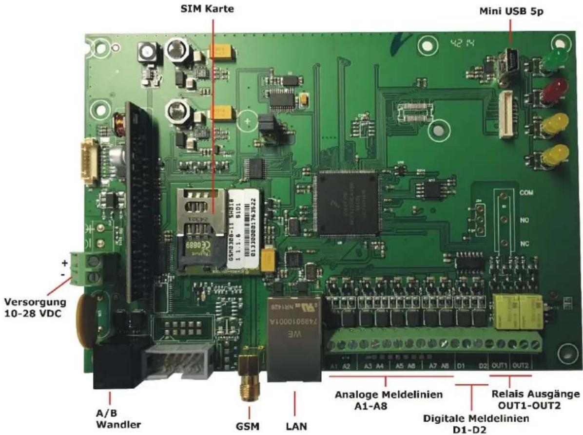
Ethernet: standard RJ45 CAT5-E connection. Plug the supplied RJ45 cable into the Ethernet port on the AZWG10200-PSTN/IP CONVERTER and connect it to the DSL modem/router. An internet connection must be available on the modem/router.
GSM antenna: connect the supplied adhesive-mounted antenna to the SMA GSM antenna connection on the AZWG10200-PSTN/IP CONVERTER. The real-time display of the signal strength in the Param-It+ software allows for the antenna position to be optimised.
10 to 28 V DC supply: the supply can be taken from the danger alarm system. A DC voltage from 10 to 28 V DC is required.
Signal lines
The motherboard is equipped with eight monitored lines (inputs). These inputs can be adjusted per line and used as NO (normally open) or NC (normally closed) contacts. They are monitored with a resistance of 10 K or with two resistances of 8 K2/15 K (8 K2 idle, 23 K2 when there is an alarm; zero and open lead to tampering/fault). Separate settings are provided for connection to Siemens or Bosch fire alarm systems.
Plugs:
L1 C L2 L3 C L4 L5 C L6 L7 C L8
Lx = monitored line (zone)
C = common
D1 = digital line (zone) 1
C = common
D2 = digital line (zone) 2

Outputs
The two relay outputs are marked with OUT1 and OUT2.
OUT1 NO transmission error if an alarm notification is not accepted within three attempts
OUT2 NC fault with LAN, GPRS communication, supply, start (booting)
OUT1 is active when there is a transmission error. The reset occurs after a notification is acknowledged. OUT2 can be configured for each connection path.
USB
The USB port has a 5-pin USB mini connection, which is used for programming, firmware updates and diagnostics.
Converter connection (POTS)
The PSTN converter with the RJ11 port provides the option of connecting an analogue alarm system with SIA, Contact ID or Telim. The converter is supplied with a line voltage of 40 V for the dialling tone, Telim, SIA and Contact ID as well as for evaluation and conversion to VdS 2465 IP or DC-09 IP transmission protocols. The telephone number and ID number must be set in the alarm system; see chapter 'Param-It+ programming'.
SIM card
The SIM card must support GPRS (2G) IP data transmission. For redundant use, 1 MB per month is sufficient. The AZWG10200-PSTN/IP CONVERTER supports multi-roaming SIM cards.
LED displays
The AZWG10200-PSTN/IP CONVERTER has the following LEDs:

Green Continuously illuminated: supply OK, device is ready for operation
FLASHING fast: device is starting (booting)
FLASHING slow: tampering on the signal line/extension or fault with power supply

Red Continuously illuminated: transmission active
FLASHING fast: 10 second notification acknowledged by receiver
FLASHING slow: dialler repetition

Yellow L (1) Continuously illuminated: converter active

Yellow R (2) FLASHING briefly ON – long OFF: Ethernet/LAN fault
FLASHING long ON – briefly OFF: GPRS/GSM fault
Continuously illuminated: Ethernet/LAN and GPRS/GSM
fault
Programming with Paramlt+
All parameters for the AZWG10200-PSTN/IP CONVERTER can be configured using the ParamIt+ software. ParamIt+ is the software for programming and troubleshooting the AZWG10200-PSTN/IP CONVERTER and updating its firmware, both directly via USB connection and via remote configuration.
Install ParamIt+ and start it by double-clicking the icon. The software is available on the ABUS homepage.

If no users have been created yet, ParamIt+ starts with a standard login screen.

Press 'OK' or 'Enter' to continue to the start page.

Some administrative information can be stored under premises data. The IP address and port can be entered for remote access to the AZWG10200-PSTN/IP CONVERTER. Port 64001 is used by default for remote access. The port number can be changed under Options > Settings > Remote access/upgrade.
Check whether the AZWG10200-PSTN/IP CONVERTER is supplied with power and connect the device to the computer/.laptop via the mini USB cable or use the 'Remote access' option to connect.

The external IP address can be entered for remote access to the AZWG10200-PSTN/IP CONVERTER.

Remote access progress is displayed on the right-hand side:
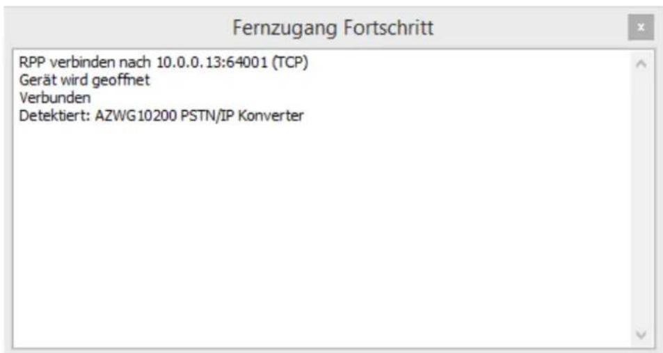
ParamIt+ automatically detects the AZWG10200-PSTN/IP CONVERTER and opens the start screen. The product information is displayed along with the firmware version. The status of the USB or remote connection is indicated at the bottom left of the screen with a green icon.

If password protection is enabled on the AZWG10200-PSTN/IP CONVERTER, the login window opens:

If you do not know the password, the device can be reset using the 'Factory setting' key. ATTENTION! All programming data will be deleted when this key is pressed!
Separate passwords can be assigned for remote access and the USB (on-site) connection.
Password required: password required for remote access
Required for USB connection: password also required for connection via USB
A new password can be entered by selecting 'Change password'. The new password is only active once it has been transmitted from the PC to the AZWG10200-PSTN/IP CONVERTER by pressing the 'Send' key.

Configurations saved on the computer/laptop can easily be loaded.
Press the folder icon at the top left:

A new window opens with the saved files. Select the desired file and press 'Open'. The file is then loaded.
Importing a configuration from the AZWG10200-PSTN/IP CONVERTER
The configuration saved on the AZWG10200-PSTN/IP CONVERTER can easily be imported using the 'Receive' key.

Press OK again to confirm.
Saving a configuration on the PC/laptop
The newly created or changed programming can be saved by pressing the key with the diskette icon on it. A new window opens. Enter a file name and press 'Save'.

The files are saved to the following destination by default: \My Documents\ParamIt+\Parameters. The save location can be changed in the save menu. Subfolders can also be created.
Saving a configuration on the AZWG10200-PSTN/IP CONVERTER
The newly created or changed programming can be saved on the AZWG10200-PSTN/IP CONVERTER by pressing the 'Send' key.

Changing a configuration
The configuration of the AZWG10200-PSTN/IP CONVERTER is ideally changed by working through the tabs from left to right. Many settings are configured by default.

The settings for the GSM, Ethernet (LAN), converter and time server hardware modules are configured in the 'Modules' tab.

• APN: provider access point
- User name: GPRS (2G) provider login
- Password: GPRS (2G) provider login
• PIN code: used if there is a PIN on the SIM card
Ethernet/LAN module
The Ethernet module is the LAN port on the PCB and allows for transmission via Ethernet.
ON √ Ethernet/LAN module enabled for transmission and remote access
√ Obtain IP address automatically (DHCP)
- If this option is ticked, the AZWG10200-PSTN/IP CONVERTER automatically obtains the network settings via DHCP
Ethernet/LAN
- Enter the desired data for a fixed IP address, gateway and subnet mask. (If these fields are greyed out, the tick mark for 'Obtain IP address automatically (DHCP)' must be removed.)
Smart IP configuration active
- If DHCP is not enabled, the 'Smart IP configuration active' option can be ticked. Then if the entered data
does not work or stops working and no connection can be established, the data can be obtained via DHCP after several failed attempts to connect using the entered data.
Time server
- The AZWG10200-PSTN/IP CONVERTER uses the NTP time server to synchronise the time automatically. With the VdS 2465 and DC-09 protocols, the time is transmitted for each notification for EN 50136 'Verification of Performance' (VoP). In the case of public internet connections, the public addresses of the time server should be entered here (e.g. ntp.pool.org or NTP Deutsche Telekom AG: 195.145.119.188). If the AZWG10200-PSTN/IP CONVERTER is used in a closed network (VPN), the addresses of the VPN time server must be entered. If no time server is available, the device does not transmit the time with notifications. The AZWG10200-PSTN/IP CONVERTER synchronises the time every hour via Ethernet or GSM.
Converter module
The converter module reads the Telim, SIA and Contact ID notifications from the alarm system.
ON √ Converter enabled
√ ON alarm system transmission
- Selection for Telim, SIA or Contact ID alarm systems. The level is automatically evaluated for SIA. Program 901 as the first call number in the alarm system in order to enable transmission through the AZWG10200-PSTN/IP CONVERTER.
'Transmission' tab
The communication options, the data of the IP receiver at the monitoring station and the notification order are set in the 'Transmission' tab. The AZWG10200-PSTN/IP CONVERTER provides a free choice between using the primary path or opting for redundant transmission. Up to eight different combinations of communication and receiver options can be set.
The settings consist of:
- Module, communication via AZWG10200-PSTN/IP CONVERTER:
- Ethernet UDP or TCP. The choice of UDP or TCP should match the setting of the monitoring station receiver.
○ GPRS UDP or TCP. The choice of UDP or TCP should match the setting of the monitoring station receiver.
- Target type: transmission method. Currently only IP address is possible.
- Address: IP address of the monitoring station receiver.
- Port: port number of the monitoring station receiver. The monitoring station often differentiates between the primary path and redundant path using the port numbers.
• Direction: set to 'Outgoing'.
- Alarm protocol:
- SIA DC3, first generation SIA IP transmission. DC3 and UDP can only be combined if there is a fixed IP address for the premises.
o SIA DC9, second generation SIA IP transmission including text.
o SIA DC9 Encrypt: the DC9 notification is encrypted via AES. The encryption method can be set in the 'Encryption' tab. The encryption should also be set on the monitoring station receiver in order to ensure problem-free receipt of the data.
- SIA DC-09 A.ASCII: SIA DC-09 variant, compatible with receivers from Azur (Osiris) and ESI (F1). These are mostly used in France and Belgium.
- SIA DC-09 A.Encrypt: SIA DC-09 variant with encryption compatible with receivers from Azur (Osiris) and ESI (F1). These are mostly used in France and Belgium. The encryption method can be set in the 'Encryption' tab. The encryption should also be set on the monitoring station receiver in order to ensure problem-free receipt of the data.
- CID DC-09: second generation IP transmission in Contact ID DC-09 structure.
- CID DC9 Encrypt: second generation IP transmission with encryption in Contact ID DC-09 structure. The encryption method can be set in the 'Encryption' tab. The encryption should also be set on the monitoring station receiver in order to ensure problem-free receipt of the data.
○ VdS 2465 needs-based: IP transmission in VdS 2465 structure including text as needs-based connection.
- VdS 2465 needs-based encrypt.: IP transmission in VdS 2465 structure including text with encryption as needs-based connection. The VdS 2465 notification is given an AES 128 key and key number when sent. The key and key number should also be set on the monitoring station receiver in order to ensure problem-free receipt of the data.
- ID no.: the identification number for the notification to the monitoring station must have no less than four and no more than eight digits. Set the same ID number in the alarm system.
Sequence:
The sequence determines the order of the notifications. The notifications from the danger alarm system are sent via the PSTN converter in sequence 1. This is normally first the primary path and then the redundant path. The test, dialler and AZWG10200-PSTN/IP CONVERTER notifications can be set up using the setting sequence for a receiver.
- Sequence 1 ...: call order 1 etc.
- Target 1 ...: connection selection via menu
Test notifications from a specific transmission path should only be set for the target.
'Encryption' tab
The AZWG10200-PSTN/IP CONVERTER provides the option of encrypting notifications. The sent data is encrypted and sent on the IP network so that they cannot be intercepted and analysed. An AES key is stored in the device for this purpose. The characters are introduced in hexadecimal and consist of numbers from 0 to 9 and letters from A to F. There are three different degrees of encryption on the AZWG10200-PSTN/IP CONVERTER.
- AES 128 encryption using 32 characters (always use AES 128 with VdS protocol)
• AES 192 encryption using 48 characters
• AES 256 encryption using 64 characters
Set the same AES encryption on the monitoring station receiver in order to decrypt the notifications upon their receipt. Coordinate this with the monitoring station. Select alarm protocol VdS 2465 or DC-09 with encryption as the transmission protocol in the 'Transmission' tab.
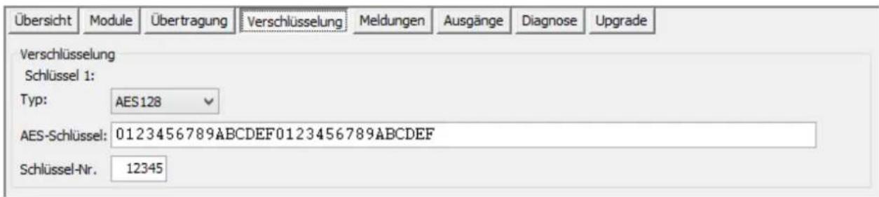
The key number is only used with the VdS 2465 protocol. The number is limited to five digits and must not be zero.
'Notifications' tab
There are four sub-categories in the 'Notifications' tab.

Alarm lines (eight monitored analogue inputs)
The AZWG10200-PSTN/IP CONVERTER has eight analogue inputs that are freely configurable for EN 54-21 fire and fault notifications or multiple breaking and entering and technical notifications. The following settings can be configured for each input:
- wiring, input type; the following options are available for this:
- Not active: input is switched off
○ Normally Open: input is normally open, operating current (NO)
○ Normally Closed: input is normally closed, standby current (NC)
- 10K monitored: input is monitored via 10KΩ in normal state
○ Double resistance monitored: monitored with double resistance; 8K2 in normal state, 23K2 in alarm state, opened or short-circuited in the event of tampering
- Siemens FAC N.O.: configuration for normally open contact of a Siemens fire alarm system
- Siemens FAC N.C.: configuration for normally closed contact of a Siemens fire alarm system
- Bosch FAC N.C. fire: configuration for normally closed contact of a BOSCH fire alarm system and fire notification
- Bosch FAC N.C. error: configuration for normally closed contact of a BOSCH fire alarm system and error notification.
- Delay in hours, minutes and seconds: if the input resets back to normal state within the set delay time, no notification is issued.
- Sequence: notifications are handled/processed as per the sequence set in the 'Transmission' tab.
- Alarm: as soon as the input is enabled.
- Reset: as soon as the input is reset to normal state. If 'No reporting' is set, this notification is not sent.
- Area: notification partition.
- Text: free text field with 16 characters. This text is sent when the inputs go into 'Alarm' and 'Reset' states. Use only characters A to Z, 0 to 9 and do not use bookmarks or international characters.
The selected protocol coding for the line notification is displayed in the window below.
AUX lines (two digital inputs, high/low)
The two digital inputs of the AZWG10200-PSTN/IP CONVERTER can be used for the tamper contact, for example.

- wiring, input type; the following options are available in the menu:
-
Not active: input is switched off
○ Normally Open: input is normally open, operating current (NO)
○ Normally Closed: input is normally closed, standby current (NC) -
Delay in hours, minutes and seconds. If the input resets back to normal state within the set delay time, no notification is issued.
- Sequence: notifications are sent as per the sequence set in the 'Notifications' tab. There is a special sequence in the upload/download menu for enabling the upload/download connection.
- Alarm: as soon as the input is enabled. There is a special sequence under 'Start up/download panel' for enabling the upload/download connection.
- Reset: as soon as the input is reset to normal state. If 'NO' is selected, this notification is not sent.
• Area: sub-area of the notification. - Text: free text field with 16 characters. This text is sent when the inputs go into 'Alarm' and 'Reset' states. Use only characters A to Z, 0 to 9 and do not use bookmarks or international characters.
Test notifications (test and poll notifications)
The AZWG10200-PSTN/IP CONVERTER has eight internal timers that are used to monitor the connection paths via automatic test, poll and interval-based notifications. The timers are easy to configure using pre-settings in line with the EN risk classes. Poll notifications are used when the interval is short. These are monitored by the monitoring station receiver. Poll notifications are used in the DP classes. Timer 1 is the primary poll and timer 2 is the redundant poll in this case. If the primary path fails, timer 2 takes over the interval from timer 1. When the primary path is restored, timer 2 is reset. Test notifications are used for classes SP-1 and SP-2. A test notification is monitored by the monitoring station software rather than the receiver. The AZWG10200-PSTN/IP CONVERTER sends the test notification as a VdS, Contact ID or SIA RP, TX, RX report. When an RX report is sent and there is a GPRS connection, the ICCID number of the SIM card and the current provider can also be sent.
![Übersicht Module Übertragung Verschlüsselung Meldungen Ausgänge Diagnose Upgrade Alarminien Aux Linien Versorgung Testmeldungen TSEC 3000 System Erweiterungen Linie Zeiteinstellung Intervall Reihenfolge Meldung Funktion Texte Timer 1 Poll 00:00:20 Reihenfolge 2: 01, Poll No function Timer 2 Poll 10:00:00 Reihenfolge 3: 02, Poll No function Timer 3 Aktiv Täglich Reihenfolge 2: 01, VdS Test report No function Timer 4 Aktiv Zeit Reihenfolge 1: 01,02, Timed function Analog input 4 Timer 5 Nicht aktiv 00:00:00 Leer No function Timer 6 Nicht aktiv 00:00:00 Leer No function Timer 7 Nicht aktiv 00:00:00 Leer No function Timer 8 Nicht aktiv 00:00:00 Leer No function VdS: - Time setting, enabling of timer via menu selection: Not active: timer is disabled ○ Active: timer is enabled; can be set via the 'Advanced timer settings' menu Poll: poll notifications are enabled; can be set via the 'Poll times' menu - Interval, time interval in hours, minutes and seconds. The poll interval time is automatically set when an EN risk class is selected and given a green background. When a timer is enabled (no poll), the desired interval must be set in the 'Advanced timer settings' menu. - Sequence: notifications are processed as per the sequence set in the 'Transmission' tab. - Notification, selection of poll, test and interval notifications: ○ VdS Test report: selection for needs-based test notification with VdS 2465 protocol. ○ Automatic test: standard SIA RP automatic test notification. - Manual test: SIA RX test notification with the option of transmitting the SIM ICCID number of the SIM card in the text field of each test notification; %\$01 must be entered in the text field for this purpose. - No reporting: no transmission. ○ Poll: setting for poll test notifications. Select 'Manual' (specific timer setting) for EN risk class. - Timed function: setting for interval when measuring analogue values such as temperature. The desired interval must be set in the 'Advanced timer settings' menu. - Function: for 'Timed function' only; select the line that needs to transmit a current measured value after the interval. - Text: free text field with max. 16 characters. This text is sent with each test or poll notification. Only use if required, because this option leads to excessive data amounts. Advanced timer settings The desired interval must be set here if a timer is enabled. An interval can be set to daily, weekly or monthly via four tabs. Press 'Use per timer' to apply the setting. [The current AZWG10200-PSTN/IP CONVERTER, system, date/time and the next test notification are displayed on the right-hand side.] AZWG10200-PSTN/IP CONVERTER system The system and transmission notifications can be set in this tab. The cover switch is not used for the AZWG10200-PSTN/IP CONVERTER PCB. text_image Übersicht Module Übertragung Verschlüsselung Meldungen Ausgänge Diagnose Upgrade Alarminien Aux Linien Testmeldungen System Linie Überwachung Verzögerung Reihenfolge Alarm Rückstellung Bereich Text Deckel Schalter: Nicht aktiv 00:00:00 Oberfläche löschen GSM IP: Aktiv 00:02:00 Reihenfolge 2: 01, GSM IP fail GSM IP ok 0 GSM Vorort Ethernet IP: Aktiv 00:00:20 Reihenfolge 3: 02, Eth. IP fail Eth. IP ok 0 LAN Vorort VdS: 34/B4 System Einstellung Bereich überbrücken 255](/content/2026/05/797420/images/ba0301a5988c2f7bdcc0dc59f7c8e20fe05e0bd593f23735dc38a16e90a30db3.jpg)
- Line:
• Cover switch: not used -
GSM IP; the locally monitored GSM/GPRS network consists of:
-
PIN code error
- GSM login error
- GPRS IP address not received
o Signal strength too low; login failed
- ETH IP; the locally monitored Ethernet consists of:
- Physical connection with LAN disrupted
- Ethernet error (MAC address, ARP)
- IP address not received
• Monitoring, system notification enabled; the following options are available in the menu:
- Not active: system notification disabled
○ Active: system notification enabled
- Delay, interval in hours, minutes and seconds: if the system notification resets back to normal state within the set delay time, no notification is issued.
- Sequence: notifications are processed as per the sequence set in the 'Transmission' tab. Note: a failed Ethernet connection cannot be reported via an Ethernet connection.
- Alarm, fixed error coding:
- TA0001 Tamper alarm active
- YS0009 GSM IP fail
- YS0013 Ethernet IP fail
- Reset, reset notification with fixed coding:
- TR0001 Tamper alarm restore
◦ YK0009 GSM IP OK
○ YK0013 Ethernet IP OK
• Area: notification partition.
- Text: free text field with 16 characters. This text is sent when the inputs go into 'Alarm' and 'Reset' states. Use only characters A to Z, 0 to 9 and do not use bookmarks or international characters.
- System setting:
○ Bypass area: the AZWG10200-PSTN/IP CONVERTER provides the option of blocking notifications from this area.
Outputs
The AZWG10200-PSTN/IP CONVERTER is equipped with two relay outputs.

The motherboard has two relays:
OUT1/relay 1
OUT2/relay 2
The relay settings can be configured in this tab.
Relay 1 is mostly used for transmission errors. If the AZWG10200-PSTN/IP CONVERTER has still not received any acknowledgement after the third transmission attempt, this relay is enabled. As soon as an acknowledgement is received, the relay is reset.
Relay 2 must be set for EN 54-21 applications in accordance with VdS regulations. This relay is enabled if an error occurs with the supply, the transmission paths, during programming or with the processor. Once the error is reset, the relay is also reset. Select the 'Standby current for EN 54-21/VdS applications' option.
Attention: Once the AZWG10200-PSTN/IP CONVERTER has received new data via the 'Send' key, the converter is automatically restarted and the current status of all active notifications is sent. During startup the green LED flashes for approx. one minute and the left of the two yellow LEDs flashes approx. two minutes, until all connection paths are active and the server receives the correct time.
Diagnosis
There are four sub-tabs in the 'Diagnosis' tab:
- Modules: status of GSM, Ethernet, supply, converter and time
- Alarm lines: status of all inputs
• Outputs: status of all relays
• System: event log (log book)
Diagnosis > Modules
Ethernet LAN


Wandler analoge Port

Uhr
System Datum / Uhrzeit 2-2-2017 12:43:33
GSM
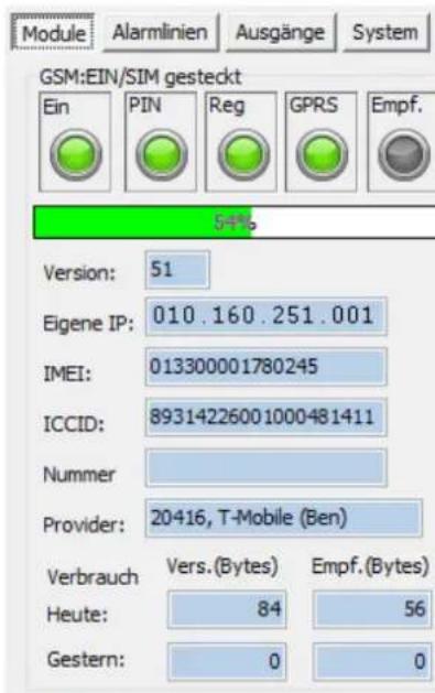
The GSM diagnostics are provided on the left-hand side. A green indicator means that there are no errors.
On GSM module enabled
PIN PIN code matches SIM card
Reg SIM card is registered on the network
GPRS SIM card has received an IP address and can connect via IP
Receive GSM is set up to receive (only possible in closed networks)
Signal strength
This value is refreshed within a few seconds and provides the option of determining the optimal position of the antenna.
0% - 16% (red) -> very weak antenna signal
16% - 25% (yellow) -> very weak but usable antenna signal
25% - 35% (green) -> moderate antenna signal
35% - 67% (green) -> good antenna signal
67% - 100% (green) -> strong antenna signal
Version Software version of the GSM module
Own IP IP address received from the GSM network
IMEI Serial number of the GSM module
ICCID SIM identification number
Number GSM call number, if not blocked
Provider Provider through which the AZWG10200-PSTN/IP
CONVERTER has established a connection, if not blocked
Consumption Display of sent and received bytes from today and yesterday
Clock
Status of date and time synchronisation. The background colour indicates the status:
Green Clock is correctly set and synchronisation is possible
Yellow Clock is correctly set but no time server is programmed
Red Clock is not set and is not (yet) synchronised (when restarting it may take some time before synchronisation is complete)
Ethernet/LAN
The LAN/(Ethernet) diagnostics are provided on the right-hand side. A green indicator means that there are no errors.
On Ethernet/LAN module is active
LAN LAN/network cable connected
ETH Ethernet active, valid MAC address
IP IP address received from the network, DHCP OK
DHCP DHCP settings active
Own IP Assigned or set IP address
DNS1 IP address of domain name server 1 (not used) DNS2 IP address of domain name server 2 (not used) Gateway Assigned or set gateway Subnet mask Assigned or set subnet mask DHCP server IP address of the DHCP server on the network MAC: MAC address of the AZWG10200-PSTN/IP CONVERTER
Converter analogue port
The converter diagnostics show whether the danger alarm system is active on the analogue port.
Active Black filled-in circle; analogue alarm system connection is active
Call number Display of (last) imported call numbers from the alarm system
Dialler process Idle: port idle
Dial tone: AZWG10200-PSTN/IP CONVERTER
generates dial time for alarm system
Modem training: analyse communication type (requirement tones)
Data state: (Telim) (SIA) (CID) detected protocols
Diagnosis > Alarm lines
The status of the signal lines can be read out using the 'Alarm lines' sub-tab of the 'Diagnosis' tab.
The cover switch status is not used with the AZWG10200-PSTN/IP CONVERTER.
Module | Alarmlinien | Ausgänge | System

bar
| System | Deckelschalter | Label | |---|---|---| | Klar | 1: | 2: | | Verzögerung | 2: | 1: | | Alarm/Aktiv | 3: | 2: | | Sabotage | 4: | 3: | | Unbekannt | 5: | 4: | | Deaktiviert | 6: | 5: | | Deaktiviert | 7: | 6: | | Deaktiviert | 8: | 7: | | Deaktiviert | 8: | 8: | Legend Legend SystemMonitored lines on the motherboard: Eight alarm inputs A1-A8 of the ZWG10200-PSTN/IP CONVERTER motherboard
Digital lines on the motherboard Two AUX inputs D1, D2 of the AZWG10200-PSTN/IP CONVERTER motherboard
Key: Green: input in 'Reset' state
Orange: in delay time
Red: active for alarm or fault
Yellow: tampering (on double resistance monitored inputs)
Black: unknown, not configured
Grey: input is disabled
Diagnosis > Outputs
The status of the relays can be read out using the 'Outputs' sub-tab of the 'Diagnosis' tab. Only the diagnostics for the two relays on the motherboard are described here:

Relay:
PCB:
1 OUT1 Status of relay 1, default is transmission error
2 OUT2 Status of relay 2, default is VdS/EN 54-21 fault function
Key: Green: relay in idle state
Red: active relay in alarm state
Black: unknown, not configured
Diagnosis > System
The event log can be read out using the 'System' sub-tab of the 'Diagnosis' tab. The event log is divided into: transmission and system.

Done Green, AZWG10200-PSTN/IP CONVERTER is ready for operation Red, AZWG10200-PSTN/IP CONVERTER is not (yet) ready (restart)
Log book Green, log book available Red, log book not available (not supported)
Error in index An error has occurred in the listed index number, such as a transmission error
Index Consecutive number Line Input or output of the AZWG10200-PSTN/IP CONVERTER
Notification VdS, SIA or Contact ID notification Trigger time Time of alarm or fault Acknowledged Time of acknowledgement from receiver and display of target
Clicking on the index line displays detailed data for the content of the notification, including the processing time.
If there is an error in the index, clicking on the index for the content of a notification displays detailed data for the error, including the processing time.

The event log is imported up until the last restart or max. 250 index lines. The next notifications are loaded by scrolling down and double-clicking the ↓ cursor or 'PgDn' when the last notification is reached.
If new notifications occur while connecting to the event log, these are displayed behind the 'Refresh' key. Use the 'Clear interface' key to delete the log book in ParamIt+.

Upgrade
The firmware of the AZWG10200-PSTN/IP CONVERTER can be easily upgraded using the 'Upgrade' tab.

Select the desired upgrade on the left-hand side. Detailed information on the upgrade is displayed on the right-hand side. If the upgrade matches the variant of the AZWG10200-PSTN/IP CONVERTER, the 'Start upgrade' key becomes active. Press 'Start upgrade' and follow the procedure on the screen.

If a different hardware version of the AZWG10200-PSTN/IP CONVERTER is connected, an error message will be displayed at the bottom of the screen.
Upgrade nicht zugelassen. (Unterschiedliche Geräte, TSEC3000E-GP)
Technical data
| Product name | PSTN/IP Converter |
| Article number | AZWG10200 |
| Manufacturer | ABUS Security-Center GmbH & Co. KG |
| Operating temperature | -25 °C to +60 °C |
| Dimensions (LxWxH) | 150 x 190 x 64 mm |
| Weight | 0,338 Kg |
| Power consumption | Closed-circuit current70 mAMax. current170 mA |
| Operating voltage | 10-28V DC |
| Frequency range | GSM/GPRS: 900 MHz and 1800 MHz |
| Max. radio output power | 2W at 850/900 MHz1W bat 1800/1900 MHz |
| Communication | • 10/100 Mb LAN/Ethernet-Port• USB-Program-Port• GSM/GPRS-Communication module |
| Outputs | 2 Relays outputs |
| Protocols | VdS 2465, Contact-ID und SIADC-9 TCP/UDP |
| Alarm lines | 8 supervised Alarm lines |
| LED | 4 Pieces:- 1xGreen- 1x Red- 2x Yellow |
Warranty
Note
ABUS products are designed and manufactured with the greatest care and tested according to the applicable regulations.
The warranty only covers defects caused by material or manufacturing errors at the time of sale. If there are demonstrable material or manufacturing errors, the module will be repaired or replaced at the guarantor's discretion.
In such cases, the warranty ends when the original warranty period of two years expires. All further claims are expressly rejected.
ABUS does not accept liability for defects and damage caused by external influences (e.g. transport, use of force, operating errors), inappropriate use, normal wear and tear or failure to observe the instructions in this manual.
In the event of a warranty claim, the original receipt with the date of purchase and a short written description of the problem must be supplied with the product.
Disposal
-
Dispose of the device in accordance with EU Directive 2012/19/EC – WEEE (Waste Electrical and Electronic Equipment). If you have any questions, please contact the municipal authority responsible for disposal. You can find information on collection points for waste equipment from your local community and city government, from local waste disposal companies or your dealer.
Declaration of conformity
ABUS Security-Center GmbH & Co. KG hereby declares that the device with item number AZWG10200 complies with the essential requirements and other relevant provisions of Directives 2011/65/EC, 2014/30/EC. The declaration of conformity can be obtained from the following address:
ABUS Security-Center GmbH & Co. KG
Linker Kreuthweg 5
86444 Affing
GERMANY
Notes
- Preface
- Safety information
- Contents
- Preface....2
- Safety information.... 2
- Contents 3
- Introduction 5
- Safety information....6
- General information....7
- Power supply 7
- Hardware modules 7
- Alarm transmission....7
- Installation and connection 9
- Motherboard connections....11
- LED displays....13
- Programming with Paramlt+....13
- Diagnosis....30
- Upgrade....37
- Introduction
- Information on user manual
- Intended use
- Limitation of liability
- Explanation of symbols
- Packaging
- Danger
- General information
- Power supply
- Hardware modules
- IP Ethernet (LAN)
- IP/GPRS (GSM)
- A/B converter
- Alarm transmission
- EN-compliant transmission
- Redundant transmission
- Installation and connection
- Installation
- Motherboard connections
- Signal lines
- Outputs
- USB
- Converter connection (POTS)
- SIM card
- LED displays
- Programming with Paramlt+
- Changing a configuration
- Ethernet/LAN module
- Ethernet/LAN
- Smart IP configuration active
- Time server
- Converter module
- 'Transmission' tab
- The settings consist of:
- Sequence:
- 'Encryption' tab
- 'Notifications' tab
- Alarm lines (eight monitored analogue inputs)
- Test notifications (test and poll notifications)
- Advanced timer settings
- AZWG10200-PSTN/IP CONVERTER system
- - System setting:
- Diagnosis
- Diagnosis > Modules
- GSM
- Signal strength
- Clock
- Converter analogue port
- Diagnosis > Alarm lines
- Module | Alarmlinien | Ausgänge | System
- Diagnosis > Outputs
- Relay:
- Diagnosis > System
- Upgrade
- Warranty
- Note
- Disposal
- Declaration of conformity
- Notes
Brand : ABUS
Model : AZWG10200
Category : Power inverter