StorageLibrary T24 - Data Storage Tandberg Data - Free user manual and instructions
Find the device manual for free StorageLibrary T24 Tandberg Data in PDF.


User questions about StorageLibrary T24 Tandberg Data
0 question about this device. Answer the ones you know or ask your own.
Ask a new question about this device
Download the instructions for your Data Storage in PDF format for free! Find your manual StorageLibrary T24 - Tandberg Data and take your electronic device back in hand. On this page are published all the documents necessary for the use of your device. StorageLibrary T24 by Tandberg Data.
USER MANUAL StorageLibrary T24 Tandberg Data
Securing your Information

natural_image
Three blue-toned globe illustrations showing continents with no text or symbols on the globe itselfStorageLIBRARY T24
Product Manual
Part Number 433686 Rev. 02
| COPYRIGHT | Copyright 2007 by Tandberg Data Corporation. All rights reserved. This item and the information contained herein are the property of Tandberg Data Corporation. No part of this document may be reproduced, transmitted, transcribed, stored in a retrieval system, or translated into any language or computer language in any form or by any means, electronic, mechanical, magnetic, optical, chemical, manual, or otherwise, without the express written permission of Tandberg Data Corporation, 2108 55th Street, Boulder, Colorado 80301. |
| DISCLAIMER | Tandberg Data Corporation makes no representation or warranties with respect to the contents of this document and specifically disclaims any implied warranties of merchantability or fitness for any particular purpose. Further, Tandberg Data Corporation reserves the right to revise this publication without obligation of Tandberg Data Corporation to notify any person or organization of such revision or changes. |
| TRADEMARKNOTICES | Tandberg Data trademarks: Tandberg Data, Exabyte, the Exabyte Logo, EZ17, M2, VXA, and VXAtape are registered trademarks; ExaBotics, MammothTape, and SmartClean are trademarks; SupportSuite is a service mark.Other trademarks: Linear Tape-Open, LTO, the LTO Logo, Ultrium and the Ultrium Logo are trademarks of HP, IBM, and Quantum in the US and other countries. All other product names are trademarks or registered trademarks of their respective owners. |
| PART NUMBER | 433686 Revision 02 |
Revision HISTORY Revision Date Description
01 November 2006 Initial release.
02 April 2007 Update for new shipping lock, new error codes, new tape drive, minor changes.
NOTE: The most current information about this product is available at Tandberg Data's web site (www.tandbergdata.com).
PRODUCT WARRANTY CAUTION
The StorageLibrary T24 by Tandberg Data Corporation is warranted to be free from defects in materials, parts, and workmanship and will conform to the current product specification upon delivery. For the specific details of your warranty, refer to your sales contract or contact the company from which the library was purchased.
The warranty for the library shall not apply to failures caused by:
▶ Physical abuse or use not consistent with the operating instructions or product specifications.
Repair or modification by any one other than Tandberg Data's personnel or agent in a manner differing from the maintenance instructions provided by Tandberg Data.
▶ Removal of the Tandberg Data identification label(s).
▶ Physical abuse due to improper packaging of returned library.
If problems with the library occur, contact your maintenance organization; do not void the product warranty by allowing untrained or unauthorized personnel to attempt repairs.

Caution
Returning the library in unauthorized packaging may damage the unit and void the warranty. If you are returning the library for repair, package it in its original packaging (or in replacement packaging obtained from your vendor.)
CONTACTING TANDBERG DATA CORPORATION
| To obtain general information | |
| Tandberg Data CorporationHeadquarters | Tandberg DataKjelsåsveien 161PO Box 134 Kjelsås0411 OsloNorway |
| + 47 2218 9090 | |
| World Wide Web www.tandbergdata.com | |
NOTES
Contents
About This Manual ...... xv
1 Product Overview .... 1
Library Features ...... 1
Library Components 3
2Installing the Library 9
Obtaining Accessories and Equipment 10
Preparing for Installation....12
Installing the Library in a Rack 13
Assembling the Rails 13
Attaching the Rails to the Rack 15
Attaching the Library to the Rails 16
Connecting to SCSI....17
Connecting the Library to Fibre Channel. 20
Connecting the Library to Ethernet 21
Connecting the Library to the USB Port 21
Powering On the Library 22
Verifying the Hardware Installation 30
3Configuring the Library 33
Accessing Configuration Options 33
Setting Configuration Options. 39
Checking the Setup 84
4Using the Remote Management Utility ..... 87
Accessing the Remote Management Utility 87
Viewing the Home Page 89
Setting Configuration Options. 96
Viewing Information on the Statistics Page 105
Using the Utility's Tools 107
5Operating the Library....117
Preparing Cartridges. 119
Inserting and Moving Cartridges 120
Loading Cartridges into a Magazine 124
Removing Cartridges from the Library 126
Issuing a Re-inventory Command to the Library ..... 128
Loading and Unloading Cartridges in the Tape Drive . . . . . . . . . 129
Cleaning the Tape Drive 132
Resetting the Library 138
Storing Cartridges. 140
6Viewing Library Information....141
Viewing Basic Library Information 141
Viewing Library Status 143
Viewing Library History 144
Viewing Library Statistics 146
Viewing Library Settings 152
Viewing Basic Tape Drive Information 153
Viewing and Updating the Cartridge Inventory 158
7 Maintenance....165
Installing or Replacing a Tape Drive 165
Installing a Second Half Height Tape Drive. 169
Replacing a Tape Drive (same configuration) ..... 171
Replacing a Tape Drive (Half height to Full height) ..... 175
Reconfiguring the Library and Resuming Operation ..... 178
Removing Cartridges Without Power 181
Cleaning the Library....183
Running Tape Drive Diagnostics....183
Running Library Diagnostics 185
FTP—Library Firmware Upgrade and Diagnostics ..... 190
LibTool—Library Firmware Upgrade 193
USB Port—Library Firmware Upgrade and Diagnostics. . . . . . . . 193
LTOTool—Tape Drive Firmware Upgrade 196
USB Port—Tape Drive Firmware Upgrade ..... 196
8 Troubleshooting 199
Library Troubleshooting 199
Tape Drive Troubleshooting 202
Backup Software Reports an Error. 204
Before Contacting Technical Support 206
Advanced Troubleshooting 208
ASpecifications. 209
Storage Capacity 209
Size and Weight 210
Performance Specifications....210
Power Specifications. 212
Environmental Specifications 213
Shipping Specifications 215
Universal Serial Bus (USB) Interface 215
Safety and Regulatory Agency Compliance 215
B Interface Specification.... 219
SCSI Interface Specifications 219
Fibre Channel Interface Specifications (FC Tape Drive) ..... 226
Ethernet Specifications 227
C Write Once, Read Many (WORM) Capability ..... 229
Overview 229
WORM Media 229
Requirements 231
TapeAlert Flags 231
Error Codes 232
D Shipping the Library 233
Preparing the Library for Shipping. 233
Replacing the Shipping Lock. 235
Removing the Library from the Rack 239
Packing the Library 240
E Error Messages 243
Library LCD Error Messages 243
Library "Fatal" Error Messages....254
Index 257
Figures
1 Product Overview
Figure 1-1 StorageLibrary T24 front panel components ..... 3
Figure 1-2 Library's back panel components (SCSI configuration) ..... 5
Figure 1-3 Library's back panel components (FC configuration). . . . . . . . . 6
Figure 1-4 StorageLibrary T24 internal components ..... 7
2Installing the Library
Figure 2-1 Assembling the left-side rail 14
Figure 2-2 Assembling the right-side rail 14
Figure 2-3 Attaching the left-side rail to the rack....15
Figure 2-4 Placing the library on the rails 16
Figure 2-5 Attaching the library to the rails at the back of the rack. . . . . . 17
Figure 2-6 SCSI connectors....19
Figure 2-7 Fibre Channel connector 20
Figure 2-8 Ethernet port (SCSI library shown) 21
Figure 2-9 USB port (Fibre Channel library shown) ..... 21
Figure 2-10 Shipping locks 22
Figure 2-11 Power switch and power connector 23
Figure 2-12 Shipping lock replacement preparation-step 1 ..... 24
Figure 2-13 Shipping lock removal-plastic shipping lock step 1 . . . . . . . . . 25
Figure 2-14 Shipping lock removal-plastic shipping lock step 2 . . . . . . . . . 25
Figure 2-15 Shipping lock removal-standard shipping lock step 1 ..... 26
Figure 2-16 Shipping lock removal-standard shipping lock step 2 . . . . . . . 26
Figure 2-17 Shipping lock removal-standard shipping lock steps 3 and 4 .. 27
Figure 2-18 Shipping lock removal-standard shipping lock step 5 ..... 28
Figure 2-19 Shipping lock removal-three prong shipping lock . . . . . . . . . 29
3Configuring the Library
Figure 3-1 Library LCD and keypad 33
Figure 3-2 Library menu organization .... 39
4 Using the Remote Management Utility
Figure 4-1 Remote Management Utility–Home page....88
Figure 4-2 Remote Management Utility–Library and Tape Drive Status . . . 91
Figure 4-3 Remote Management Utility-Status window ..... 92
Figure 4-4 Remote Management Utility–Inventory page ..... 95
Figure 4-5 Remote Management Utility-Configuration Home page. . . . . . 97
Figure 4-6 Remote Management Utility–Statistics Home page. ..... 105
Figure 4-7 Remote Management Utility–Tools Home page ..... 107
5Operating the Library
Figure 5-1 Location of status LED 118
Figure 5-2 Bar code label placement and write-protect switch location .. 119
Figure 5-3 Location of I/E Port lock button 120
Figure 5-4 Inserting a cartridge into the I/E port. 121
Figure 5-5 Magazine lock buttons....125
Figure 5-6 Loading cartridges into a magazine....125
7 Maintenance
Figure 7-1 Serial cable routing—full height tape drive....168
Figure 7-2 Serial cable routing—half height tape drives ..... 168
Figure 7-3 Power cable routing—full height tape drive ..... 168
Figure 7-4 Power cable routing—half height tape drives ..... 168
Figure 7-5 Tape drive cover plate (half height SCSI library) ..... 169
Figure 7-6 Tape drive cooling plate.... 169
Figure 7-7 Upper half height tape drive cable routing ..... 170
Figure 7-8 Tape drive cover plate (Fibre Channel library). . . . . . . . . . . . . . . . . 171
Figure 7-9 Full height tape drive's serial and power connectors ..... 173
Figure 7-10 Upper half height tape drive cable routing ..... 173
Figure 7-11 Lower half height tape drive cable routing ..... 174
Figure 7-12 Tape drive cover plate (half height SCSI library) ..... 175
Figure 7-13 Tape drive cooling plate.... 176
Figure 7-14 Full height tape drive's serial and power connectors.... 177
Figure 7-15 Manual magazine release.... 182
B Interface Specification
Figure B-1 Element addresses (I/E port enabled/no fixed cleaning slot) . . . 225
Figure B-2 Element addresses (I/E port disabled/no fixed cleaning slot) .. 225
C Write Once, Read Many (WORM) Capability
Figure C-1 Ultrium 3 WORM tape cartridge 229
DShipping the Library
Figure D-1 Shipping locks 235
Figure D-2 Shipping lock replacement-step 1 235
Figure D-3 Shipping lock replacement-plastic shipping lock step 1 ..... 236
Figure D-4 Shipping lock replacement-plastic shipping lock step 2 ..... 236
Figure D-5 Shipping lock replacement-standard shipping lock step 1....237
Figure D-6 Shipping lock replacement-standard shipping lock step 2....237
Figure D-7 Shipping lock replacement-standard shipping lock step 3. . . . 238
Figure D-9 Removing the screws securing the library to the rails ..... 239
Figure D-10 Removing the library from the rack 240
Figure D-11 Library in antistatic bag 240
Figure D-12 Bottom foam packing pieces 241
Figure D-13 Top foam packing piece (shown with accessories). 241
Figure D-14 Accessory item placement in shipping box 242
NOTES
Tables
3Configuring the Library
Table 3-1 Tape drive status messages.... 34
Table 3-2 Library command status messages 35
Table 3-3 Library command-state status messages ..... 36
Table 3-4 Operator button descriptions.... 38
Table 3-5 Library configuration options 40
Table 3-6 Emulation modes for the StorageLibrary T24 ..... 57
Table 3-7 Ethernet configuration options 67
5Operating the Library
Table 5-1 Tape drive cartridge read/write compatibility ..... 119
ASpecifications
Table A-1 Maximum library storage capacity 209
Table A-2 Library dimensions and weight.... 210
Table A-3 LTO Ultrium tape drive transfer rate and capacity.... 210
Table A-4 Power Cord Specifications 212
Table A-5 Environmental specifications 213
Table A-6 Acoustic noise limits. 214
Table A-7 Shock limits 214
Table A-8 Shipping weight and dimensions 215
B Interface Specification
Table B-1 SCSI command set supported by the library ..... 221
Table B-2 Status byte descriptions 223
Table B-3 Supported sense keys. 223
Table B-4 Multi-mode optical cable characteristics. 226
Table B-5 Ethernet port pin assignments and functions. 227
C Write Once, Read Many (WORM) Capability
Table C-1 WORM tape cartridge specifications 230
Table C-2 TapeAlert flags associated with the WORM media ..... 231
Table C-3 ASC/ASCQ error codes for a Medium Error (SK 3) with WORM media .... 232
Table C-4 ASC/ASCQ error codes for a Data Protect error (SK 7) with WORM media....232
EError Messages
Table E-1 Library error messages 244
Table E-2 Library "fatal" error messages.... 254
ABOUT THIS MANUAL
This manual describes how to install, configure, operate, maintain, and troubleshoot the StorageLibrary T24 by Tandberg Data Corporation. It also provides specifications for the library.
NOTICE-This manual may contain some preliminary information that may change without notice.
WHERE TO LOOK FOR INFORMATION
Installation
If you are performing first-time installation:
Read Chapter 1 for an overview of the library's features and components.
Read Chapter 2 for hardware installation instructions, including obtaining the necessary accessories, installing the library in a rack, installing cartridges, and connecting the library to a host system.
Read Chapter 3 for configuration instructions, including how to use the library's operator panel to access and set configuration options.
Read Chapter 4 for information about using the library's Remote Management utility to configure the library, view information, and monitor operation across an Ethernet network.
Operation
When you are ready to put the library into operation:
Read Chapter 5 to learn about inserting and removing cartridges from the library, loading and unloading cartridges in the tape drives, cleaning the tape drives, and performing other basic library operations.
Read Chapter 6 to learn about viewing library information including code versions, serial numbers, statistics, sensor readings, and cartridge inventory data.
Maintenance, Troubleshooting, and Service
If you need to perform basic library maintenance, troubleshoot problems, or return the library for service:
Read Chapter 7 for maintenance information, including instructions for replacing the tape drives, uploading new firmware, and creating diagnostic listings.
Read Chapter 8 for valuable troubleshooting tips.
Supplemental Information
Read Appendix A for physical, performance, power, environmental, Universal Serial Bus (USB), and safety agency specifications.
Read Appendix B for information about the interface specifications (SCSI and Ethernet).
Read Appendix C for information about the WORM capability of the LTO-3 tape drive.
Read Appendix D for packing and shipping instructions if you need to return the library for service.
Read Appendix E for definitions of library error messages.
RELATED PUBLICATIONS
For additional information about the library and tape drive, refer to the following publications.
StorageLibrary T24
StorageLibrary T24 Quick Start Guide, 433684
FI: Installing a StorageLoader 2U LTO or a StorageLibrary T24 Library in a Rack, 1016990
FI: Installing a Magazine in a StorageLoader 2U LTO or a StorageLibrary T24 Library, 1017082
Tandberg Data Bar Code Label Specification for LTO Ultrium Cartridges, 1004080-000
Library Safety Notices Booklet (translated warnings), 311467-006
Go to: www.tandbergdata.com
Ultrium Tape Drives
See the following web sites to locate documentation and support information for LTO Ultrium tape drives:
IBM — www.storage.ibm.com/tape/lto/oem/index.html
Hewlett Packard — www1.hp.com/storage/tapestorage.html
Standards
▶ Small Computer System Interface - 2 (SCSI-2), INCITS 131-1994[R2004]
Information Technology - SCSI-3 Primary Commands (SPC), ANSI INCITS 301-1997
Information Technology - SCSI Primary Commands-2 (SPC-2), ANSI INCITS 351-2001
▶ SCSI-3 Primary Commands (SPC), INCITS 301-1997 [R2002]
Information Technology - SCSI-3 Medium Changer Commands (SMC), ANSI INCITS 314-1998
Information Technology – SCSI Parallel Interface-3 (SPI-3), ANSI INCITS 336-2000
Information Technology - SCSI Parallel Interface-2 (SPI-2), ANSI INCITS 302-1998
Information Technology - SCSI Stream Commands-2 (SSC-2), ANSI INCITS 380-2003
TapeAlert Specification, NCITS T10/02-142R0, Version 3.0, March 2002
▶ Automation/Drive Interface - Commands (ADC), Working Draft, Revision 7, September 14, 2004
IEC 60297 Rack Standards
For general information, go to www.T10.org.
CONVENTIONS USED IN THIS MANUAL
This manual uses the following conventions:
Note: Notes provide additional information or suggestions about the topic or procedure being discussed.
! Important Read text marked by the "Important" icon for information that will help you complete a procedure or avoid extra steps.

Caution
Read text marked by the "CAUTION" icon for information you must know to avoid damaging the library, the tape drives, or losing data.

Warning
Read text marked by the "WARNING" icon for information you must know to avoid personal injury.
NOTES
1
PRODUCT OVERVIEW
Congratulations on selecting the StorageLibrary T24 by Tandberg Data Corporation. The library provides unattended data storage, archiving, backup, and retrieval for small PC workgroups to multi-server networks. The library features Tandberg Data's patented, award-winning ExaBotics™.
Your new library is equipped with one of these tape drive configurations:
One or two half height (HH) LTO Ultrium 2 (LTO-2) tape drive(s)
One or two half height (HH) LTO Ultrium 3 (LTO-3) tape drive(s)
One full height (FH) LTO Ultrium 3 (LTO-3) tape drive
Note: Ultrium 1 (LTO-1) tape drives are not compatible with this library.
This chapter provides an overview of the library's features and components.
natural_image
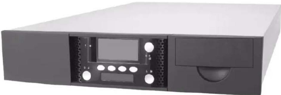
Exterior view of a black server rack unit with front panel and drive slots (no visible text or labels)LIBRARY FEATURES
The StorageLibrary T24 includes the following features:
Storage for up to 24 data cartridges. Up to 24 data cartridges are stored in the library. The magazines hold up to 12 cartridges each.
Note: The left magazine is optional. The library is shipped with the right magazine installed and a "blank" installed in the left magazine's location.
▶ Tape drives. The library contains high-performance, high-capacity LTO tape drives in one of these options:
One or two half height LTO Ultrium 2 tape drive(s)
One or two half height LTO Ultrium 3 tape drive(s)
One full height LTO Ultrium 3 tape drive
Import/Export (I/E Port). The I/E port allows you to insert and remove one cartridge at a time (such as a cleaning cartridge).
Bar code scanner. A bar code scanner allows the library to maintain an inventory of its cartridges.
Operator panel with LCD display. The operator panel allows you to monitor library operations and select configuration options.
Interface options. Depending on the tape drive(s) installed in the library, you will have one of these options. The library does not have a SCSI controller, but rather, communicates with the host using ADI "bridging" through the tape drive(s).
Wide, low-voltage differential (LVD) SCSI interface. The LVD tape drives support independent sets of SCSI messages and commands and can be connected to separate SCSI busses.
Fibre Channel (FC) interface. The Fibre Channel interface allows you to connect the library to a Fibre Channel network.
Note: The library communicates with the host through the SCSI interface of the tape drive(s) via the ADI serial interface. The SCSI interface as seen by the host is the SCSI interface of the tape drive.
See the tape drive Product Manual for tape drive information. See Automation/Drive Interface - Command (ADC) for ADI information.
Ethernet port for connection to a 10/100BaseT Ethernet network. When used with the Remote Management utility, you can connect the library to an Ethernet network for remote monitoring, upgrading library firmware, and creating diagnostic listings.
Remote Management Utility. The library's Remote Management utility allows you to use a standard web browser to set configuration options, view library information, and monitor library operations over an Ethernet network.
Universal Serial Bus Connector. The library is equipped with a Universal Serial Bus connector for running diagnostics or upgrading firmware.
Rack-mount hardware. The library is designed to mount in a standard 4-post, 19-inch rack using just 2 units (2U) of rack space. Rack-mounting hardware is included with the library. You can also operate the library as a desktop configuration.
LIBRARY COMPONENTS
The following sections describe the library's front panel, internal, and back panel components.
FRONT PANEL COMPONENTS
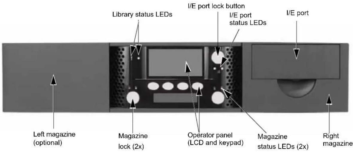
Figure 1-1 shows the library's front panel components.
text_image
Library status LEDs I/E port lock button I/E port status LEDs I/E port Left magazine (optional) Magazine lock (2x) Operator panel (LCD and keypad) Magazine status LEDs (2x) Right magazineFigure 1-1 StorageLibrary T24 front panel components
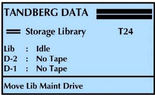
Operator Panel (LCD and Keypad) The operator panel includes a 4-button keypad and an 8-line, 21-character liquid crystal display (LCD).
text_image
TANDBERG DATA —— Storage Library T24 Lib : Idle D-2 : No Tape D-1 : No Tape Move Lib Maint DriveNote: This screen shows a library with two tape drives installed. If your library has one tape drive installed, the additional line (D-2) does not show a status.
You can use the operator panel to:
▶ Set or change library configuration options
▶ Issue commands to the library
▶ View library status and information
▶ Run demonstration programs and test library functions
Reset the library
▶ Set tape drive configuration options
▶ View tape drive status and information
Import/Export Port (I/E Port) The I/E port allows you to insert or remove cartridges from the library. To prevent unauthorized use of the I/E port, operator panel menus can be password protected or access can be prevented through the backup application.
Library Status LED The status LEDs indicate library activity as shown in the following table. See Figure 1-1 for the location of the status LEDs.
LED Color Status
| Off (no color) The library is idle | |
| Green The library is performing a mechanical operation | |
| Amber The library encountered a hardware errorSeeAppendix E, Error Messages |
I/E Port and Magazine Status LEDs The status LEDs indicate activity as shown in the following table. See Figure 1-1 for the location of the status LEDs.
LED Color Status
 | Green Locked | |
 | Amber solid | Unlocked |
 | Amber blinking | Unlocking |
I/E Port Full LED The LED for the I/E port (full/empty) indicates activity as shown in the following table. See Figure 1-1 for the location of the LED.
LED Color Status
 | Off (no color) I/E Port is empty |
 | Green I/E Port is full |
 | Green blinking I/E Port door is open |
BACK PANEL COMPONENTS
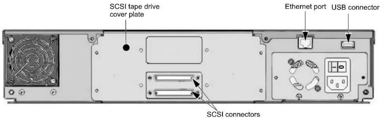
Figure 1-2 shows the back panel components of the library.
text_image
SCSI tape drive cover plate Ethernet port USB connector SCSI connectorsFigure 1-2 Library's back panel components (SCSI configuration)
Tape Drive Cover Plate The tape drive cover plate allows access to the tape drive(s) for easy replacement, if necessary.
Ethernet Port The Ethernet port allows you to connect the library to a 10/100BaseT Ethernet network. You can use the Ethernet connection to perform the following activities:
▶ Monitor library operations using its built-in Remote Management software
▶ Upload diagnostic information from the library using FTP
Upgrade the library's firmware
USB Connector. The library is equipped with a Universal Serial Bus (USB) connector for running diagnostics or upgrading firmware.
Interface connectors The library has either LVD SCSI tape drive(s) or a Fibre Channel tape drive installed.
Note: The library communicates with the host through the SCSI interface of the tape drive(s) via the ADI serial interface. The SCSI interface as seen by the host is the SCSI interface of the tape drive.
See the tape drive Product Manual for tape drive information.
IBM — www.storage.ibm.com/tape/lto/oem/index.html
Hewlett Packard — www1.hp.com/storage/tapestorage.html
See Automation/Drive Interface - Command (ADC) for ADI information.
T 10 — www.t10.org
▶ SCSI Connectors—If the tape drive(s) installed in the library have SCSI connectors, they can accommodate one of the following.
▶ Half height LTO-2 SCSI connector—An Ultra 160 SCSI connector (minimum rating) Terminator—An Ultra 3 Active SCSI terminator (minimum rating)
▶ Half height LTO-3 SCSI connector—An Ultra 160 SCSI connector (minimum rating) Terminator—An Ultra 3 Active SCSI terminator (minimum rating)
Full height LTO-3 SCSI connector—An Ultra 160 SCSI connector (minimum rating) Terminator—An Ultra 3 Active SCSI terminator (minimum rating)
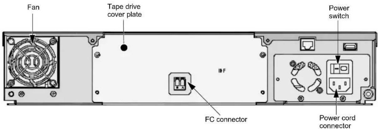
Fibre Channel Connector—If the tape drive installed in the library has a Fibre Channel (FC) connector, they accommodate connection to a 50-micron or 62-5 micron multi-mode optical fibre cable with LC connectors.
text_image
Fan Tape drive cover plate Power switch IFF FC connector Power cord connectorFigure 1-3 Library's back panel components (FC configuration)
Fan The system fan provides cooling for the library and the tape drive(s).
Power Cord Connection The power cord connection provides AC power to the library and the tape drive(s).
Power Switch The power switch allows you to turn power on and off for the library and the enclosed tape drive(s).
INTERNAL COMPONENTS
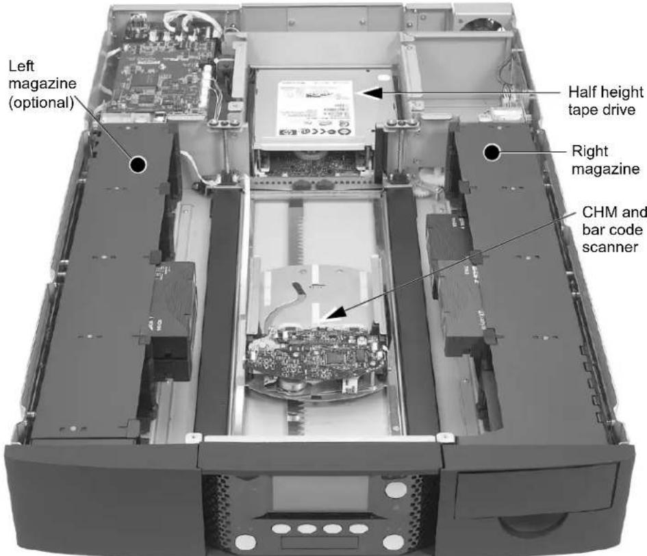
Figure 1-4 shows the library's internal components.
text_image
Left magazine (optional) Half height tape drive Right magazine CHM and bar code scannerFigure 1-4 StorageLibrary T24 internal components
Tape Drive The tape drive is mounted at the back of the library. Figure 1-4 shows the library with one HH LTO-2 tape drive installed. The library will also accommodate one FH LTO-3 tape drive, or two HH LTO-3 or HH LTO-2 tape drives.
Cartridge Handling Mechanism (CHM) The CHM moves cartridges between cells in the magazines and the tape drives. When a cartridge is ejected from a tape drive, the CHM moves the cartridge back to the magazine. The CHM also moves cartridges to the I/E port for easy removal from the library.
Bar Code Scanner The bar code scanner is located on the cartridge handling mechanism. The scanner enables the library to read information from bar code labels on the cartridges into its cartridge inventory. A backup application can use the inventory information to locate and move specific cartridges.
Magazines The library's two magazines hold up to 24 data cartridges. The I/E port is located in the magazine on the right of the library.
NOTES
2
INSTALLING THE LIBRARY
This chapter describes how to install the library. Depending on your requirements, installation will involve most or all of the following steps:
| To view this information... go to... | ||
| Obtaining accessories and equipment page 10 | ||
| Preparing for installation page 12 | ||
| Installing the library in a rack page 13 | ||
| Connecting to SCSI page 17 | ||
| Connecting to Fibre Channel page 20 | ||
| Connecting the library to Ethernet (optional) page 21 | ||
| Connecting the library to the USB Port page 21 | ||
| Powering on the library Powering-on page 22 | ||
| Removing the Shipping Lock page 23 | ||
| Verifying the hardware installation | page 30 | |
! Important
After unpacking the library, save all the original packing materials in case you need to ship or move the library later.
OBTAINING ACCESSORIES AND EQUIPMENT
Make sure that you have all the accessories and equipment for library installation and operation, as indicated in the following table. If necessary, you can purchase these items from Tandberg Data (see "Contacting Tandberg Data Corporation" on page iii).
! Important
Both LTO-2 and LTO-3 SCSI tape drives are Ultra 160 SCSI devices and require a minimum Ultra 160 non-RAID SCSI host bus adapter card, Ultra 160 rated SCSI cabling, and an Ultra 3 Active SCSI terminator.
| Accessories and Equipment | ||||
| Rack-Mount Hardware | The library is designed to be installed in a standard 4-post, 19-inch rack, using 2 units (2U) of rack space. Rack-mount hardware for a 4-post rack is provided with the library.Note:A 2-post rack will not support the library. | |||
| SCSI Cable One | high-density (HD), wide (68-pin), 2-meter LVD SCSI cable is provided with the library.Note:If your SCSI controller has a 68-pin very high-density (VHDCI) connector, you will need to obtain a VHDCI-to-HD SCSI cable. | HD Connector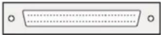 VHDCI Connector VHDCI Connector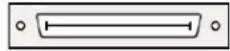 | ||
| If you want to use your own SCSI cable(s), follow these guidelines:•Use high-density, wide (68-pin) Ultra 160 SCSI cables that conform to SCSI-3 specifications. To comply with the regulations and standards listed in Appendix A, all SCSI cables used with the library must be properly shielded.•The maximum allowable length of an LVD SCSI bus is 12 meters (39 feet) if you have more than two devices on the bus. | ||||
| SCSI Bus Terminator | One wide Ultra 3 Active SCSI terminator is provided with the library. If you want to use your own terminator, use a high-quality Ultra 3 rated Active SCSI terminator. An appropriate terminator is stamped with Ultra 3 or LVD 160 and “Active Negation.”Important!Both LTO-2 and LTO-3 SCSI tape drives require an Ultra 3 or LVD 160 terminator to function properly on the SCSI bus. An inadequate terminator will result in various SCSI bus issues, including bus hangs and Read/Write failures. | |||
| Fibre Channel Cable | No Fibre Channel cables are included with the library. The number of optical fiber cables required for attaching the library to a Fibre Channel network depends on how many tape drives are installed.Use either 50-micron or 62.5-micron multi-mode optical fiber cables with dual single-channel (LC) connectors.•50-micron multi-mode optical fiber cables must comply with the 400-M5-SN-I classification as specified in the Fibre Channel standard (FC-PI-2).•62.5-micron multi-mode optical fiber cables must meet the 400-M6-SN-I classification.Note:The length of 62.5 micron multi-mode cables should not exceed 70 meters. | |||
| Ethernet Cable | One Ethernet cable is provided. You can use this cable to connect the library to an Ethernet network for remote monitoring, firmware upgrades, and diagnostics.■If you want to provide your own Ethernet cable—use a shielded Category 5 (10/100BaseT connection) data-grade cable or similar Category 5 cable that is compliant with EIA/TIA 568.■The library's Ethernet port connector is a pin-through-hole RJ-45 shielded connector. To comply with the regulations and standards listed in Appendix A, all Ethernet cables used with the library must be properly shielded. | |||
| Power Cord | Two power cords are provided with the library: one for use in the US and Canada and one for use in Europe. Refer to page 212 if you plan to use the library outside of these locations. | |||
| Bar code labels | Sample bar code labels for the cartridges are included with the library. If you want to prepare your own labels—refer to the Tandberg Data Bar Code Label Specification for LTO Ultrium Cartridges at www.tandbergdata.com. | |||
| Cartridges | Use only data cartridges and cleaning cartridges designed specifically for LTO Ultrium tape drives. The LTO tape drives support the following LTO Ultrium cartridges. | |||
| Tape Drive Supported Cartridges Color Native Capacity | ||||
| LTO-3 | Ultrium 3 Slate Blue | 400 GB | ||
| Ultrium 2 Purple | 200 GB | |||
| Ultrium 1 (READ only) | Black | 100 GB | ||
| WORM (see Appendix C) | Two-toned | 400 GB | ||
| LTO-2 | Ultrium 2 Purple | 200 GB | ||
| Ultrium 1 | Black | 100 GB | ||
| ■For maximum capacity, use Ultrium 3 data cartridges with Ultrium 3 (LTO-3) tape drives and Ultrium 2 data cartridges with Ultrium 2 (LTO-2) tape drives.■Use only LTO Ultrium cleaning cartridges | ||||
| Tools | You need to obtain these tools. | |||
| Tool | Used for | |||
| Phillips screwdriver—#1 | Standard Shipping Lock Removal | |||
| Phillips screwdriver—#2 | Installing the Library in a RackInstalling or Replacing a Tape Drive | |||
| Small, flat-blade screwdriver (or similar object) | Removing Cartridges Without Power | |||
| Level | Installing the Library in a Rack | |||
| Tape measure | Installing the Library in a Rack | |||
PREPARING FOR INSTALLATION
Before installing the library:
Make sure that the SCSI host bus adapter card installed in the host computer, any necessary device drivers, and your backup software are compatible with the library. Make certain that an Ultra 160 SCSI host bus adapter (HBA) and any necessary drivers installed in the host computer are compatible with the tape drive(s).
! Important
Both LTO-2 and LTO-3 SCSI tape drives are Ultra 160 SCSI devices and require a minimum Ultra 160 non-RAID SCSI host bus adapter card.
For optimum performance, use an Ultra160 SCSI host bus adapter. Compatibility information is available from www.tandbergdata.com.
If your software has not yet been certified for the StorageLibrary T24, you can use one of the library's emulation modes (see page 57).
You can install the software on the host computer before or after library installation. However, if you install the software first, you may need to reconfigure it for use with the library after library installation is complete.
Locate an appropriate area for the library. Select a location that has adequate clearance for ventilation, minimal dust and debris, and an appropriate power source. The library is designed to operate either in a desktop configuration, or in a standard 19-inch rack. To provide adequate air flow, a ventilated rack is recommended.
The library must be operated in the horizontal position. Do not place the library on its side, and do not place objects on top of the library.
Ensure that the work area is free from conditions that could cause electrostatic discharge (ESD). Discharge static electricity from your body by touching a known grounded surface, such as a computer's metal chassis.

Warning
Before performing any installation or maintenance procedures, be sure that the library power switch is in the off position and that the power cord is disconnected from the library and the outlet.

Warnung
The StorageLibrary T24 library is designed to be installed in a standard 4-post, 19-inch rack, using 2 units (2U) of rack space. Please read the entire section before you begin. Two-post racks will not support the StorageLibrary T24 library. The rack-mount kit includes the following items:
| 18 – M5 x 12 Crest CupTM screws (black)(includes two spare screws) | 2 – sets of side support rails(left-side front and back rails and right-side front and back rails) |
| 2 – M3 x 8 Crest Cup screws (silver) | |
| 8 – washers |
To install the library in a rack, you must obtain these tools:
| #2 Phillips screwdriver Level | Tape measure |
! Important
The rails provided with the library are designed for a 4-post rack. A 2-post rack will not support the weight of the library.
ASSEMBLING THE RAILS
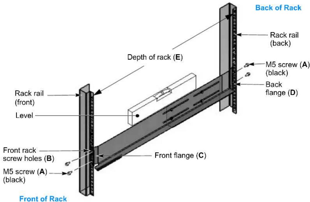
- Measure the depth of your rack—Using a tape measure, measure the inside distance from the front mounting holes of your rack to the back mounting holes. See Figure 2-3, distance (E).
-
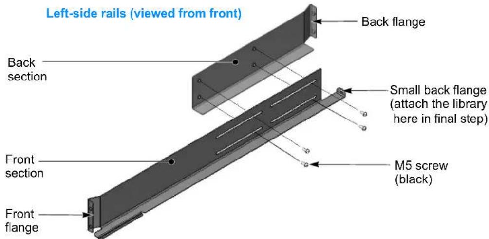
Position the front and back sections of the left-side rail as shown in Figure 2-1, with the front rail section on top of the back rail section. Spread the sections to the distance you measured in step 1.
-
Assemble the left rail using four M5 screws. Keep the screws loose so that you can adjust the length of the assembled rail, if necessary.
text_image
Left-side rails (viewed from front) Back flange Back section Small back flange (attach the library here in final step) Front section M5 screw (black) Front flangeFigure 2-1 Assembling the left-side rail
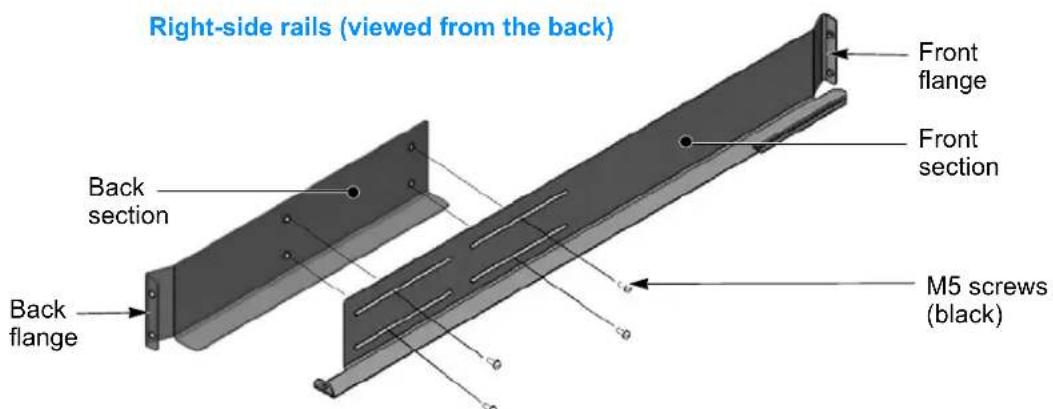
- Assemble the right-side rail in the same way.
text_image
Right-side rails (viewed from the back) Back section Back flange Front flange Front section M5 screws (black)Figure 2-2 Assembling the right-side rail
ATTACHING THE RAILS TO THE RACK
- Left side rail assembly—Position the left-side rail assembly in the rack so that the front flange is behind the front screw holes in the rack.
text_image
Back of Rack Rack rail (back) Depth of rack (E) M5 screw (A) (black) Back flange (D) Rack rail (front) Level Front rack screw holes (B) M5 screw (A) (black) Front flange (C) Front of RackFigure 2-3 Attaching the left-side rail to the rack
- Front of rack—Insert an M5 screw (A) through one of the front rack screw holes (B) and engage the pem nut in the rail flange (C). If your rack has square mounting holes or the holes are much larger than the screws provided in the kit, use a washer. Finger-tighten the screw.
Insert an M5 screw (A) through a second screw hole (B) and engage the pem nut on the second screw hole in the rail flange (C). If necessary, use a washer. Finger-tighten the screw.
-
Adjust the length of the rail assembly as necessary to fit the depth of the rack (E).
-
Back of rack—Make sure the rail assembly is level, and then use M5 screws (A) to attach the back flange (D) of the rail to the inside of the rack, using the same procedure as step 2. If your rack has square mounting holes or the holes are much larger than the screws provided in the kit, use a washer. Finger-tighten the screws.
-
Using a #2 Phillips screwdriver, tighten the screws securing the rails to the front and back of the rack.
-
Using a #2 Phillips screwdriver, tighten the four screws holding the rail assembly together.
-
Right side rail assembly—Repeat steps 1 through 6 for the right-side rail assembly. Make sure that the right rail assembly is at the same level as the left rail assembly.
ATTACHING THE LIBRARY TO THE RAILS
 | Warning | The library weighs 43 pounds (19.5 kg). Two people are needed to move or lift the library. Most of the weight is toward the back of the library. |
 | Warnung | Die Library wiegt 19.5 kg. Es sind mindestens 2 Personen erforderlich, um die Library zu bewegen oder zu heben. Der hintere Teil Library hat das größte Gewicht. |
 | Advertencia | La biblioteca montada sobre bastidor pesa 19.5 kg. Se necesitan dos personas para mover o levantar la biblioteca. La parte trasera de la biblioteca es la de mayor peso. |
To attach the library to the rails:
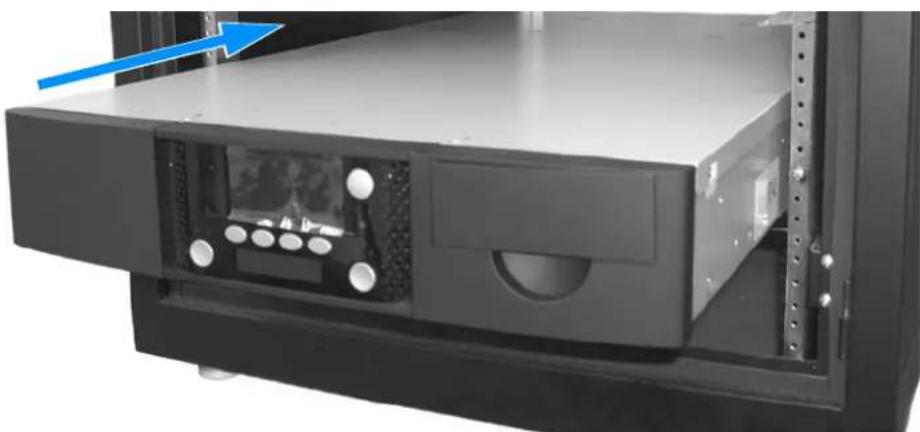
- From the front of the rack, place the library onto the shelf created by the rails.
natural_image
Interior view of a server rack unit with drive bays and a blue arrow indicating direction (no text or symbols visible)Figure 2-4 Placing the library on the rails
-
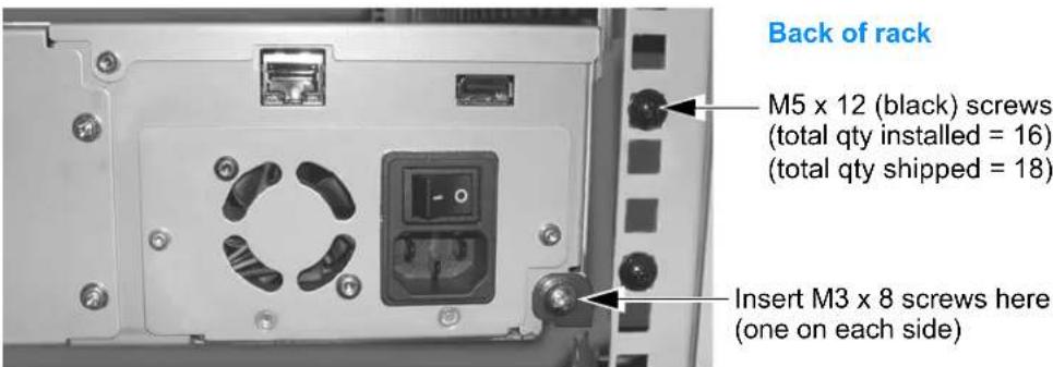
Remove the shipping lock from the library (if it is still installed). Carefully slide the library all the way back until it makes contact with the small flanges at the back of the rails (see Figure 2-5).
-
From the back of the rack, attach the library to the rails by inserting an M3 (the two smaller screws) screw into each of the small flanges. Tighten the screws using a #2 Phillips screwdriver.
text_image
Back of rack M5 x 12 (black) screws (total qty installed = 16) (total qty shipped = 18) Insert M3 x 8 screws here (one on each side)Figure 2-5 Attaching the library to the rails at the back of the rack
CONNECTING TO SCSI
The library communicates with the host through the SCSI interface of the tape drive(s) via the ADI serial interface. See Figure 1-2 on page 5 for the location of the tape drive SCSI connectors.
The SCSI interface as seen by the host is the SCSI interface of the tape drive. The library appears as LUN (Logical Unit Number) 1 on the same SCSI ID as the tape drive.
See the tape drive's Product Manual for tape drive information IBM — www.storage.ibm.com/tape/lto/oem/index.html Hewlett Packard — www1.hp.com/storage/tapestorage.html
See Automation/Drive Interface - Command (ADC) for ADI information T10 — www.T10.org
This section provides guidelines for connecting the tape drive(s) in the library to a host system via SCSI. Up to 16 devices can be connected to a wide LVD SCSI bus.
Note: To ensure optimum tape drive performance, connect the tape drive(s) to an Ultra3 (Ultra160) SCSI host bus adapter.
! Important
Both LTO-2 and LTO-3 SCSI tape drives are Ultra 160 SCSI devices and require a minimum Ultra 160 non-RAID SCSI host bus adapter card, Ultra 160 rated SCSI cabling, and an Ultra 3 Active SCSI terminator.

Caution
Do not connect the tape drive(s) to a high-voltage differential (HVD) SCSI bus. Doing so may damage the library, tape drive, or other devices on the bus.
GUIDELINES FOR CONNECTING TO SCSI
Keep these guidelines in mind as you plan your SCSI connections:
Do not connect to an inadequate host bus adapter.
! Important Both LTO-2 and LTO-3 SCSI tape drives are Ultra 160 SCSI devices and require a minimum Ultra 160 non-RAID SCSI host bus adapter card.
Do not connect single-ended SCSI devices. Although single-ended SCSI is compatible with the tape drive's LVD SCSI interface, Tandberg Data does not support connecting single-ended devices to the SCSI bus attached to the tape drives.
Do not connect the tape drives to a RAID controller. The library will not operate if the tape drives are connected to a RAID controller.
Do not exceed SCSI bus length restrictions. The maximum allowable length of an LVD SCSI bus is 12 meters (39 feet) if you have more than two devices on the bus. Make sure the SCSI bus attached to the tape drives does not exceed this length.
Make sure the SCSI bus is properly terminated. You must install a terminator on the device at the physical end of the SCSI bus. If one of the tape drives in the library terminates the SCSI bus, you must install the required terminator on one of the tape drive's SCSI connectors.
If there are additional devices on the SCSI bus, ensure that only the device at the physical end of the bus is terminated.
! Important Both LTO-2 and LTO-3 SCSI tape drives require an Ultra 3 or LVD 160 terminator to function properly on the SCSI bus. An inadequate terminator will result in various SCSI bus issues, including bus hangs and Read/Write failures. See “Tape Drive Fails with Sporadic Errors” on page 203.
MAKING THE SCSI CONNECTIONS
-
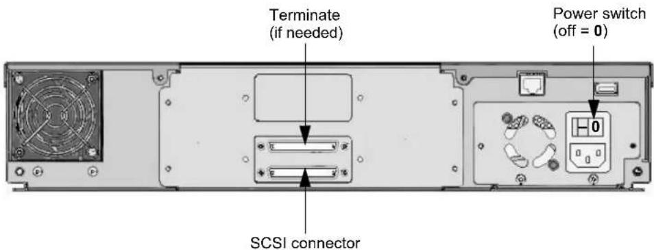
Power off the library (press the 0 on the back of the unit).
-
Power off the host.
text_image
Terminate (if needed) Power switch (off = 0) SCSI connectorFigure 2-6 SCSI connectors
- Connect a SCSI cable to the host computer and to one of the tape drive SCSI connectors.
! Important Do not over-tighten the SCSI cable jack screws.
- If the tape drive in the library is the last device on the SCSI bus, install a terminator on the unused SCSI connector.
! Important Both LTO-2 and LTO-3 SCSI tape drives require an Ultra 3 or LVD 160 terminator to function properly on the SCSI bus. An inadequate terminator will result in various SCSI bus issues, including bus hangs and Read/Write failures. See "Tape Drive Fails with Sporadic Errors" on page 203.
Daisy-chaining—If the tape drive is not the last device on the SCSI bus, or if you have two tape drives installed in the library, connect another SCSI cable between the tape drive and the next device on the bus.
Bus termination—If there are additional devices on the SCSI bus, ensure that only the device at the physical end of the bus is terminated.
CONNECTING THE LIBRARY TO FIBRE CHANNEL
This section provides instructions for connecting the tape drive(s) in the library to a Fibre Channel network.
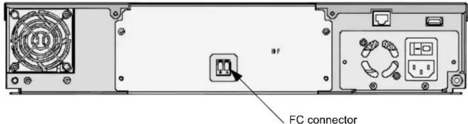
Figure 2-7 shows the back panel of the StorageLibrary T24 FC Library. Each tape drive includes one integrated dual LC optical fiber connector, Port A, for connecting the tape drive to a Fibre Channel network.
text_image
INF FC connectorFigure 2-7 Fibre Channel connector
In a Fibre Channel environment, you can connect the tape drive(s) to a Fibre Channel hub or switch in an arbitrated loop or a switched fabric. For simplicity in these instructions, each of these situations is referred to as a “network.”
To connect the tape drive(s) to a Fibre Channel network:
-
Remove the tape over the Fibre Channel connector. The tape secures the protective plugs.
-
Remove the protective plugs from the optical connectors on each tape drive. Set the plugs aside.
-
Attach an optical cable from the hub or switch to the optical fiber connector on each tape drive (if more than one tape drive is installed). The connector and the cable are keyed to ensure that the cable is attached in the correct orientation.
Note: Once the library has been powered on and the Fibre Channel loop has been initialized, avoid disconnecting the tape drive in the library from the loop. If you need to disconnect the library from the loop, use the utility provided with your switch or hub to bypass the affected ports before breaking the connection. The bypass sets the port to a non-participating state on the loop. When you have reconnected the library, use the utility to return the port to a participating state.
CONNECTING THE LIBRARY TO ETHERNET
The library's Remote Management utility (described in Chapter 4) allows you to remotely monitor operations when the library is connected to an Ethernet network. You can also create diagnostic listings and upgrade library firmware. For information about upgrading firmware and creating diagnostic listings, see page 190.
To connect the library to Ethernet using the provided cable:
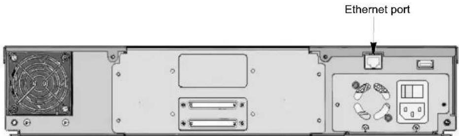
- Insert one end of the cable into the library's Ethernet port until you hear it snap into place. The Ethernet port is located on the back of the library.
text_image
Ethernet portFigure 2-8 Ethernet port (SCSI library shown)
- Connect the other end of the cable to the network or directly to the server you plan to use to run the library's Remote Management utility or upload firmware.
When you perform library configuration, you will configure the library's Ethernet interface (see page 67).
CONNECTING THE LIBRARY TO THE USB PORT
You can use the library's USB port to download firmware to the library or tape drive(s) and to perform diagnostics.
To connect the library to the USB port:
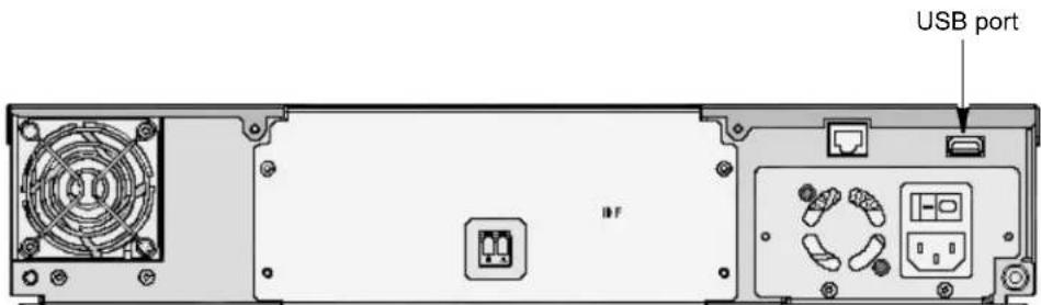
- Insert one end of the cable into the library's USB port until you hear it snap into place.
text_image
USB port IFFigure 2-9 USB port (Fibre Channel library shown)
- Connect the other end of the cable to the network or directly to the server you plan to use to run the library's Remote Management utility or to upload firmware.
See Chapter 7, "Maintenance for information about downloading firmware and performing diagnostics.
POWERING ON THE LIBRARY
This process involves two steps:
"Applying Power to the Library" on page 23
"Removing the Shipping Lock" on page 23
! Important
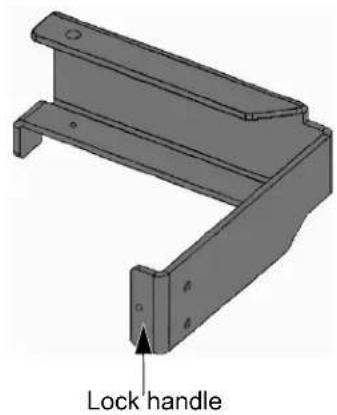
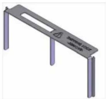
You must remove the shipping lock before operating the library. Your library shipped with one of these three shipping locks. Follow the instructions appropriate for the lock that shipped with your library.
Plastic shipping lock
text_image
Lock handle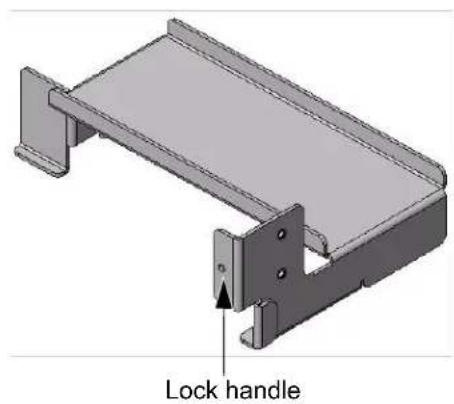
text_image
Lock handleThree-prong shipping lockStandard shippin
See page 28.
natural_image
3D rendering of a metal support structure with vertical supports and a horizontal plate (no text or symbols)Figure 2-10 Shipping locks
APPLYING POWER TO THE LIBRARY
To power on the library:
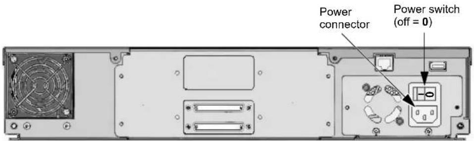
- Make sure that the power switch on the back of the library is off (the 0 is pressed).
text_image
Power connector Power switch (off = 0)Figure 2-11 Power switch and power connector
- Connect the female end of the power cord to the power connector on the back of the library.
! Important
Two power cords are shipped with the library: One for use in the US and Canada, and one for use in Europe. See page 212 for power cord requirements for other locations.
-
Plug the male end of the power cord into the power source.
-
Push the power switch on the back of the library to the "on" position (press the I). The library performs its power-on sequence.
If you previously removed the shipping lock (using the Quick Start Guide), skip the next section and continue with "Completing the Power-on Sequence" on page 29.
REMOVING THE SHIPPING LOCK
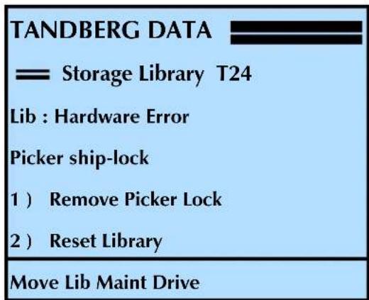
The library automatically ejects both left magazines and displays the following
message when you power it on with the shipping lock installed.
text_image
TANDBERG DATA = Storage Library T24 Lib : Hardware Error Picker ship-lock 1 ) Remove Picker Lock 2 ) Reset Library Move Lib Maint Drive"PLASTIC" AND "STANDARD" SHIPPING LOCK PREPARATION
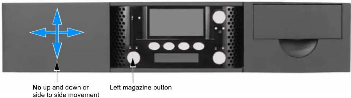
- Remove the left magazine. Press the left magazine eject button, if needed. While supporting it, gently slide the magazine straight out of the library.

Caution
Use care not to twist the magazine or move it side to side as you insert or remove it from the library. Not inserting it straight into / pulling it straight out of the opening can damage components inside the library.
text_image
No up and down or side to side movement Left magazine buttonFigure 2-12 Shipping lock replacement preparation-step 1
- Power the library off. Press the 0 on the back of the library.
- Remove the shipping lock. Follow the instructions in the appropriate section below for your shipping lock.
PLASTIC SHIPPING LOCK REMOVAL
Carefully follow these steps to properly remove the shipping lock.
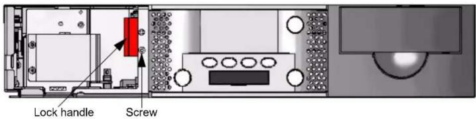
- Remove the screw. Remove the screw securing the shipping lock (the lock is shown as red in these illustrations). Keep this screw for use in a later step.
text_image
Lock handle ScrewFigure 2-13 Shipping lock removal–plastic shipping lock step 1
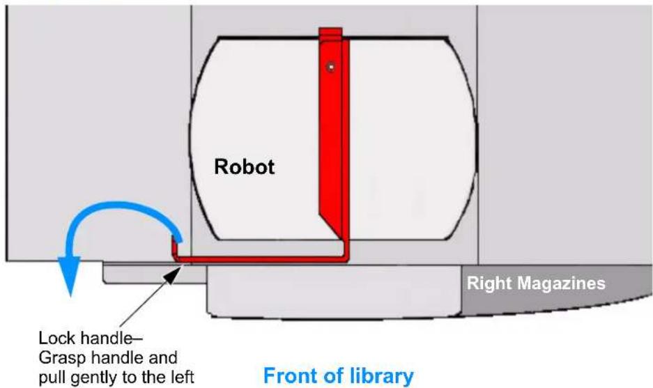
- Remove the lock. Grasp the lock handle and slowly pull the shipping lock out of the opening as shown below (you may encounter slight resistance). The lock is the red object in Figure 2-13 and Figure 2-14.
! Important
This shows the library with the top cover removed for clarity. DO NOT remove the top cover or you will void your warranty.
Top View (top cover removed for clarity)
text_image
Robot Lock handle— Grasp handle and pull gently to the left Right Magazines Front of libraryFigure 2-14 Shipping lock removal–plastic shipping lock step 2
- Replace the magazine. Securely grasp the left magazine (or magazine blank) and slide it straight into the library. Use care not to twist it or move it side to side—it must be inserted “straight” into the opening. When you encounter resistance, press the magazine firmly and it “snaps” into place.
When the magazine is fully seated, the lock icon is solid green (), indicating that it is locked.
- Continue with "Completing the Power-on Sequence" on page 29.
STANDARD SHIPPING LOCK REMOVAL
Carefully follow these steps to properly remove the shipping lock.
! Important
Some of these views show the library with the top cover removed for clarity. DO NOT remove the top cover or you will void your warranty.
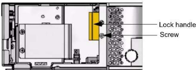
- Remove the screw. Remove the screw securing the shipping lock. Keep this screw for use in a later step.
text_image
Lock handle ScrewFigure 2-15 Shipping lock removal-standard shipping lock step 1
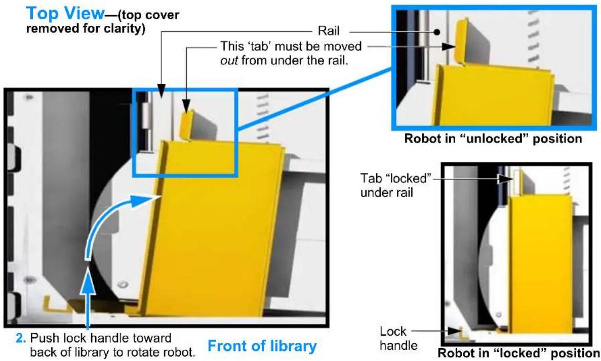
- Rotate the robot. Gently push the lock handle toward the back of the library to rotate the robot.
! Important
Do not remove the lock from the library until you perform the procedures in steps 3, and 4 below.
text_image
Top View—(top cover removed for clarity) This 'tab' must be moved out from under the rail. Rail Robot in "unlocked" position Tab "locked" under rail Lock handle 2. Push lock handle toward back of library to rotate robot. Front of library Robot in "locked" positionFigure 2-16 Shipping lock removal-standard shipping lock step 2
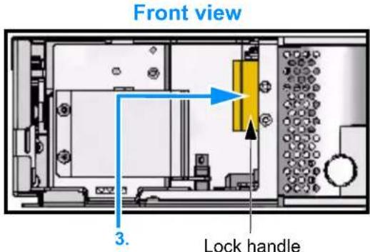
- Dislodge the shipping lock-first step. Grasp the lock handle and gently push the lock to the right approximately one inch (2.5cm). This moves the lock off of critical components on the robot.
text_image
Front view 3. Lock handle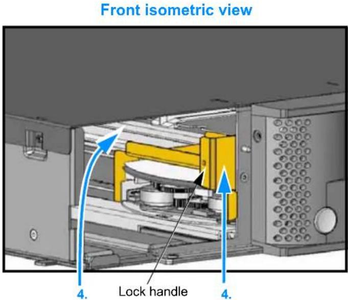
text_image
Front isometric view 4. Lock handle 4.Figure 2-17 Shipping lock removal-standard shipping lock steps 3 and 4
! Important
If you do not remove (rotate and lift) the lock as described in the next two steps, you can "catch" and damage cables inside the library and render it useless.
- Dislodge the shipping lock-second step. While holding the lock handle, carefully rotate the back of the lock up toward the top of the library approximately two inches (5cm), and then lift the front of the lock up approximately two inches (5cm).
Lifting the lock completely above the robot enables you to remove it without damaging the robot.
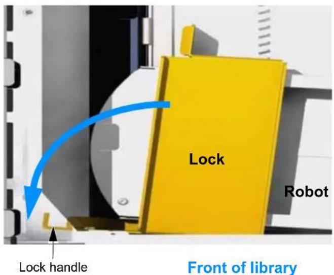
- Remove the shipping lock. With the lock lifted above the robot, slowly pull the shipping lock out of the opening as shown below.
text_image
Lock Robot Lock handle Front of libraryFigure 2-18 Shipping lock removal-standard shipping lock step 5
- Replace the magazine. Securely grasp the left magazine (or magazine blank) and slide it straight into the library. Use care not to twist it or move it side to side—it must be inserted “straight” into the opening. When you encounter resistance, press the magazine firmly and it “snaps” into place.
When the magazine is fully seated, the lock icon is solid green (), indicating that it is locked.
- Continue with "Completing the Power-on Sequence" on page 29.
THREE PRONG SHIPPING LOCK REMOVAL
Carefully follow these steps to properly remove the shipping lock. It is not necessary to power on the library to remove this shipping lock.
- Gain access to the top of the library—If you have access to the top of the library, continue with step 2.
If you installed the library in a rack prior to removing the shipping lock and no longer have access to the top of the library, follow these steps:
a. Disconnect the rack-mount screws at the back of the library (see Figure 2-5 on page 17).
b.Slide the library forward a few inches.

Caution
Do not slide the library too far forward or it will tip out of the rack!
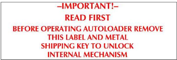
- Remove the adhesive label securing the lock to the top of the library.
text_image
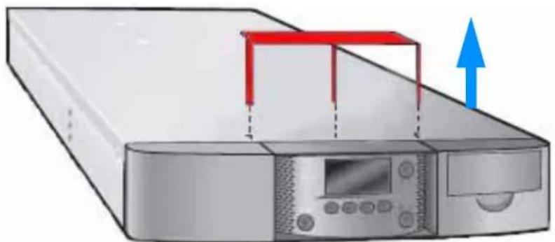
-IMPORTANT!- READ FIRST BEFORE OPERATING AUTOLOADER REMOVE THIS LABEL AND METAL SHIPPING KEY TO UNLOCK INTERNAL MECHANISM- Remove the shipping lock by carefully prying the shipping lock straight up and out of the top of the library.
natural_image
Illustration of a server rack with a monitor and control panel, showing a red bracket and blue upward arrow (no text or symbols)Figure 2-19 Shipping lock removal—three prong shipping lock
After removing the shipping lock, continue with this section.
-
Power the library on. Press the I on the back of the library.
-
Store the shipping lock. Save the shipping lock with the library's packing materials in case you need to move or re-ship the library. See Appendix D for important instructions on moving or shipping the library, including how to "park the robot."
-
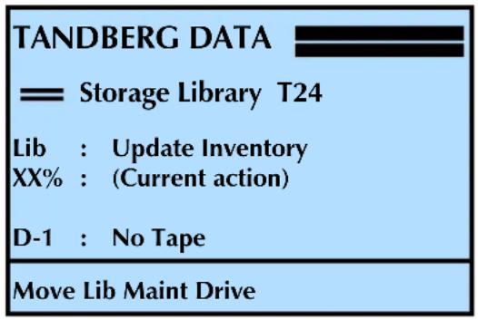
Ensure that both magazines are fully seated. Once they are fully seated, the library updates its inventory. While updating inventory, the library displays the inventory status (XX%).
text_image
TANDBERG DATA —— Storage Library T24 Lib : Update Inventory XX% : (Current action) D-1 : No Tape Move Lib Maint Drive- Set the SCSI IDs. If necessary, set the SCSI IDs for the tape drive(s)—You can use the default IDs or change them if they conflict with other devices on the SCSI bus. See page 52 for instructions.
! Important
Do not power on the host computer system immediately after powering on the library. After you power on the library, there is a short delay before the tape drive (or tape drives) are on-line.
- Final step. Power on the host computer system.
VERIFYING THE HARDWARE INSTALLATION
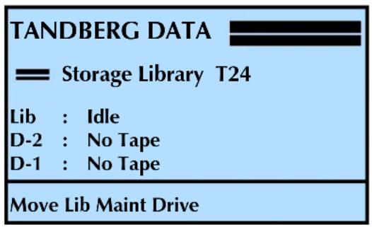
After the library powers on, the LCD displays the Home screen. The first line of the Home screen displays the product name and the following lines show status for the library and tape drive or tape drives.
text_image
TANDBERG DATA Storage Library T24 Lib : Idle D-2 : No Tape D-1 : No Tape Move Lib Maint DriveNote: This screen shows a library configured with two tape drives. If your library has one tape drive installed, the additional line (D-2) does not show a status.
If the library powered on as described, continue with configuration in Chapter 3. If not, refer to the following information.
CHECKING THE LIBRARY INSTALLATION
If the library did not power on as described, check the following:
Is the power switch on?
Is the power cord inserted correctly?
Are the devices on the SCSI bus attached to the tape drive(s) installed in the library all LVD (SCSI library)?
Is the SCSI cable firmly connected to the tape drive(s) and host computer or other devices on the bus?
Are the Fibre Channel cables firmly connected to the tape drive and Fibre Channel hub or switch (Fibre Channel library)?
Is the host computer system turned on?
Is there an error message displayed on the library's LCD? (See Appendix E for descriptions of LCD error messages.)
For additional tips, see Chapter 8, "Troubleshooting.
PERFORMING SYSTEM EXERCISES
After installing the library, check the setup by performing the exercises suggested below. While these exercises are not required, it is a good idea to verify that your system and hardware are properly communicating before you begin operation.
-
Import several cartridges into the library, and load and unload cartridges into the tape drive(s). For instructions on:
-
Importing cartridges, see page 120
Loading and unloading cartridges from the tape drives, see page 129 -
Run a system demo. See page 188 for instructions. These exercises help determine if the library's hardware components are operating properly.
- Download the diagnostic tools LibTool and LTOTool from www.tandbergdata.com. Use these two tools to verify that the host computer can communicate with the library and the tape drive(s).

flowchart
graph LR
    A["WEB"] --> B["HOST"]
    B <--> C["LIBRARY"]
Be sure to download the tools for your operating system. Refer to the instructions in the "readme" files or on-line help provided with the tools.
Use LibTool to view the cartridge inventory and to move tapes into and out of the tape drive(s).
Use LTOTool to run a Write/Read test to verify that the tape drive(s) can perform write and read operations.
If the library and tape drive(s) are not operating as expected, see:
▶ Chapter 8 for troubleshooting tips
Appendix E for error message descriptions
The troubleshooting chapter in the tape drive's product manual
If you cannot resolve the problem yourself, contact Tandberg Data Technical Support (see page iii).
3
CONFIGURING THE LIBRARY
After installing the library hardware, you are ready to set configuration options. This chapter provides the following information for the library:
| To view this information... go to... | |
| Accessing Configuration Options (this page) page 33 | |
| Home Screen Menu page 39 | |
| Setting Configuration Options page 39 | |
| Checking the Setup page 84 |
ACCESSING CONFIGURATION OPTIONS
With the StorageLibrary T24 you can use the operator panel or the library's web-based Remote Management utility to access configuration options.
To use the Operator Panel, see Using the Operator Panel (this page).
To use the Remote Management utility, see Chapter 4.
USING THE OPERATOR PANEL
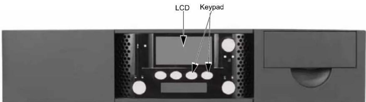
The library's operator panel includes an eight-line LCD and keypad (see Figure 3-1) that allow you to interactively control library operations. Using the operator panel, you can set library and tape drive options, execute library commands, check operating statistics, and diagnose errors.
text_image
LCD KeypadFigure 3-1 Library LCD and keypad
Viewing the Home Screen
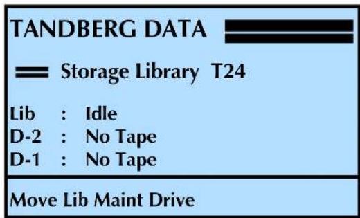
During normal operation, the Home screen appears on the LCD (see below). By default, the Home screen displays the operating status of the library and tape drive or tape drives.
text_image
TANDBERG DATA Storage Library T24 Lib : Idle D-2 : No Tape D-1 : No Tape Move Lib Maint DriveNote: This screen shows a library configured with two tape drives. If your library has one tape drive installed, the additional line (D-2) does not show a status.
Tape drive status messages Some examples of tape drive status messages are:
Table 3-1 Tape drive status messages
| Message Meaning | |
| D-n: Ready A tape is loaded in the tape drive and is ready for write or read operations. | |
| D-n: No tape No tape is loaded in the tape drive.See “Loading and Unloading Cartridges in the Tape Drive” on page 129. | |
| D-n: Tape Ejected The tape drive ejected a tape and it is located at the tape drive’s door.See “Loading and Unloading Cartridges in the Tape Drive” on page 129. | |
| D-n: Loading The tape drive is loading the tape. | |
| D-n: Unloading The tape drive is unloading the tape. | |
| D-n: Needs Cleaning The tape drive requires cleaning.See “Cleaning the Tape Drive” on page 132. | |
| D-n: Cleaning The tape drive is in the process of using a cleaning cartridge. | |
| D-n: Replace CIn Cart The cleaning cartridge has reached the end of its useful life and must be replaced. | |
| D-n: Writing+ The tape drive is currently writing data to tape with compression on. | |
| D-n: Writing The tape drive is currently writing data to tape with compression off. | |
| Message | Meaning |
| D-n: Reading The tape drive is currently reading data from the tape. | |
| D-n: Erasing The tape drive is erasing data from the tape. | |
| D-n: Locating The tape drive is locating data on the tape. | |
| D-n: Rewinding The tape drive is rewinding the tape. | |
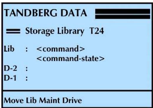
Library status messages Some examples of library status messages are shown in Table 3-2 and Table 3-3. The display for the library will be:
text_image
TANDBERG DATA Storage Library T24 Lib :Table3-2 shows the
Table 3-2 Library command status messages
| Message | Meaning |
| Idle | No command is active (the library is idle). |
| Initialize | The library is initializing hardware. |
| Abort | The library is cancelling the current command. |
| Digital Self Test | The library is executing a test of its electronics. |
| Update Inventory | The library is scanning the barcodes to update its inventory. |
| Position | The library is positioning the robot to an element (slot, I/E port, or tape drive). |
| Move Medium | The library is moving medium from one location to another. |
| Unlock I/E Port | The library is unlocking the I/E port. |
| Unlock Mag | The library is unlocking a magazine. |
| Clean Drive | The library is cleaning a tape drive. |
| Park Robot The library is parking the robot for moving or shipping. | |
Table3-3 shows the current state
Table 3-3 Library command-state status messages
| Message Meaning | |
| Calibrate The library is calibrating a mechanism. | |
| Positioning The library is positioning the robot to the desired location. | |
| Loading The library is loading a cartridge into a tape drive. | |
| Wait Drive Load The library is waiting for a tape drive to complete a load. | |
| Unloading The library is unloading a cartridge from a tape drive. | |
| Wait Drive Unload | The library is waiting for a tape drive to complete an unload. |
| Scanning The library is scanning a bar code. | |
| Unlock The library is unlocking the I/E port or a magazine. | |
| Lock | The library is locking the I/E port. |
| Picking | The robot removing a cartridge from an element (slot, I/E port, or a tape drive). |
| Putting | The robot placing a cartridge into an element (slot, I/E port, or a tape drive). |
If a hardware error occurs, an error message appears on the Home screen. Refer to Chapter 8 and Appendix E for help in diagnosing and correcting errors. You must correct the error before operation can continue.
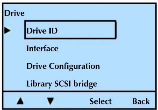
If a menu is currently displayed on the LCD and you want to view the Home screen, press the "Back" button (see example below) until the Home screen appears.
text_image
Drive ► Drive ID Interface Drive Configuration Library SCSI bridge ▲ ▼ Select Back
OVERVIEW OF LIBRARY MENUS
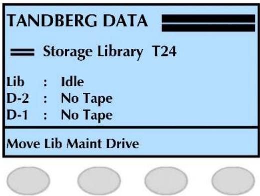
When the Home screen is displayed on the LCD, press Move, Lib, Maint, or Drive to access the library's main menus.
text_image
TANDBERG DATA —— Storage Library T24 Lib : Idle D-2 : No Tape D-1 : No Tape Move Lib Maint DriveOnce you are within a menu, press Select, Back, ▼, or ▲ to move through the main menus and see the sub-menus (see example below).
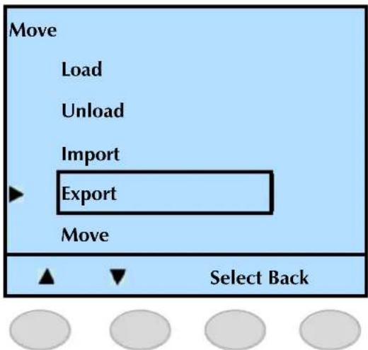
text_image
Move Load Unload Import Export Move Select BackAs shown in Figure 3-2 on page 39, the library's menus are organized in a tree structure consisting of four main menus with sub-menus and selections. The operator panel buttons allow you to move up and down between menu levels, view choices within menus, and make selections.
Table 3-2 provides an overview of the library's main menus. Figure 3-2 shows the organization of the menus.
Table 3-4 Operator button descriptions
| Button Description (press this button to:) | |
| Move | Load a cartridge into the tape driveUnload a cartridge from the tape driveImport a cartridge from the I/E portExport a cartridge through the I/E portMove a cartridge to and from a slot, the tape drive(s), or from the I/E port |
| Lib (Library) | Access the library's identification informationAccess the library's inventoryEnable, disable, or change the passwordSelect the library's languageAccess (and in some cases, change) the library's operation mode, such as:Random or Sequential cartridge handlingEmulation modeEthernet settingsLED settings (brightness, display, and appearance)Enable or disable the I/E port and set the slot countRestore defaults |
| Maint (Maintenance) | Perform library diagnostics and maintenanceRetrieve library statusReview library historyPerform a self testRetrieve library statisticsPark the library for shippingPerform tape drive diagnosticsEstablish cleaning options for clean the tape drive(s)Access USB optionsPerform a system reset |
| Drive | Access tape drive information (drive type and serial number)Access and change tape drive SCSI IDs (SCSI tape drives)Access Fibre Channel information (FC tape drives)Access and change tape drive configurationAssign the SCSI interface (bridge) |
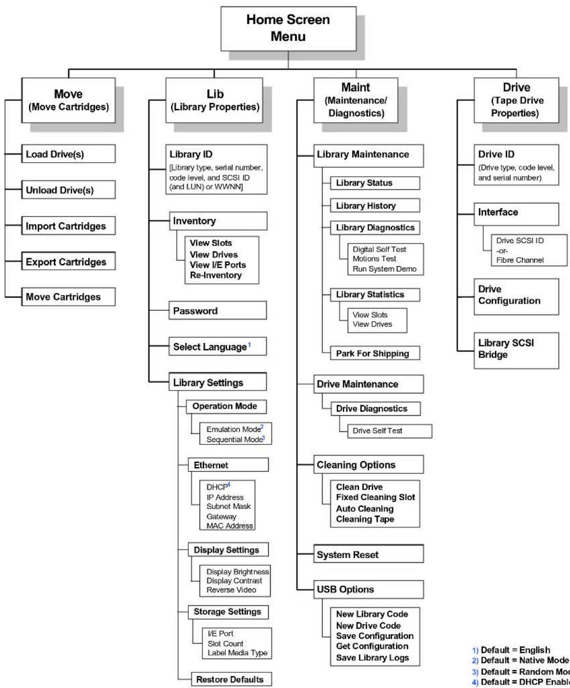
flowchart
graph TD
    A["Home Screen Menu"] --> B["Move (Move Cartridges)"]
    A --> C["Lib (Library Properties)"]
    A --> D["Maint (Maintenance/Diagnostics)"]
    A --> E["Drive (Tape Drive Properties)"]

    B --> B1["Load Drive(s)"]
    B --> B2["Unload Drive(s)"]
    B --> B3["Import Cartridges"]
    B --> B4["Export Cartridges"]
    B --> B5["Move Cartridges"]

    C --> C1["Library ID [Library type, serial number, code level, and SCSI ID (and LUN) or WWNN"]]
    C --> C2["Inventory View Slots View Drives View I/E Ports Re-Inventory"]
    C --> C3["Password Select Language¹"]

    C --> C4["Library Settings Operation Mode Emulation Mode² Sequential Mode³"]

    C --> C5["Ethernet DHCP⁴ IP Address Subnet Mask Gateway MAC Address"]

    C --> C6["Display Settings Display Brightness Display Contrast Reverse Video"]

    C --> C7["Storage Settings I/E Port Slot Count Label Media Type"]

    C --> C8["Restore Defaults"]

    D --> D1["Library Maintenance Library Status Library History Library Diagnostics Digital Self Test Motions Test Run System Demo"]
    D --> D2["Library Statistics View Slots View Drives Park For Shipping"]

    E --> E1["Drive ID (Drive type, code level, and serial number)"]
    E --> E2["Interface Drive SCSI ID-or-Fibre Channel"]
    E --> E3["Drive Configuration"]
    E --> E4["Library SCSI Bridge"]

    D --> D2
    D --> D3["Drive Maintenance Drive Diagnostics Drive Self Test"]

    D --> D4["Cleaning Options Clean Drive Fixed Cleaning Slot Auto Cleaning Cleaning Tape"]

    D --> D5["System Reset"]
    D --> D6["USB Options New Library Code New Drive Code Save Configuration Get Configuration Save Library Logs"]

    style A fill:#f9f9f9,stroke:#333
    style B fill:#e6f7ff,stroke:#333
    style C fill:#e6f7ff,stroke:#333
    style D fill:#e6f7ff,stroke:#333
Figure 3-2 Library menu organization
SETTING CONFIGURATION OPTIONS
This section provides step-by-step instructions for setting library configuration options. The instructions assume that you are using the operator panel to set options. If you are using the library's Remote Management utility (described in Chapter 4), the selections are generally the same but you access menus and selections through web-style links and fields.
Table3-5 provides an overview of each configuration option. Read through the table to determine which options you need to set, and then follow the steps on the referenced pages.
Table 3-5 Library configuration options
| Configuration option | Description See... | |
| LCD Language You can change the language for the LCD display from English (the default setting) to French, German, Italian, or Spanish. | “Changing the LCD Language” on page 41 | |
| LCD Contrast LCD Brightness Reverse Video | You can set the LCD’s contrast and brightness to an appropriate level for your lighting conditions. You can also reverse the display (dark background/light text). | “Changing the LCD settings” on page 42 |
| Slot Count (cartridge cells) | You can limit the number of slots visible to the SCSI interface for compatibility with backup software. | “Setting the Data Cartridge Slot Count” on page 47 |
| I/E Port You can enable the I/E port for importing and exporting cartridges without removing an entire magazine or you can disable the I/E port and gain one more cartridge storage slot. | “Enabling and Disabling the I/E Port” on page 49 | |
| Media Identifier You can configure the library to identify the type of media loaded into the library (LTO-2 or LTO-3) and list the information along with the barcode. | “Enabling the Media Identifier” on page 50 | |
| Tape Drive SCSI ID The tape drive(s) must have separate SCSI IDs. You can view the default settings and change them if necessary.Notes:▪The library communicates with the host through the SCSI interface of the tape drive(s) via the ADI serial interface.▪The SCSI interface that the host sees is the SCSI interface of the LTO tape drive.▪See the tape drive Product Manual for tape drive information.▪See Automation/Drive Interface - Command (ADC) for ADI information. | “Changing the SCSI IDs” on page 52 | |
| Tape Drive SCSI Interface Bridge | You can assign one of the tape drive’s to act as the primary SCSI interface (bridge) for the library. | “Tape Drive SCSI Interface (Library Bridge)” on page 54 |
| Tape Drive Configuration | If you change the tape drives in your library, you must set the tape drive configuration to match the tape drive(s) that are installed in the library. | “Tape Drive Configuration” on page 55 |
| Emulation Mode Changing the emulation mode is required if your backup application does not support the StorageLibrary T24, but does support one of these products:■Exabyte 221L library■Exabyte EZ17 autoloader■Exabyte 210 library | “Changing the Emulation Mode” on page 57 | |
| Operation Mode (Random or Sequential) | The operation mode (Random or Sequential) determines how cartridges are processed by the library.■Random–The library processes cartridges according to commands issued from an application.■Sequential–The library processes cartridges sequentially without direction from an application. | “Setting the Library to Operate in Sequential Mode” on page 59 |
| Fixed Cleaning Slot Autoclean | These options allow you to set up automatic tape drive cleaning.Note:To use automatic cleaning, a cleaning cartridge must be installed in the library (see page 135). | “Setting Up Automatic Tape Drive Cleaning” on page 63 |
| DHCP Addressing IP Address Subnet Mask Gateway Address MAC Address | If you are using the library’s Ethernet interface, you can set the library’s IP address, subnet mask, and gateway address for communication across your Ethernet network. You can also choose whether the library uses a fixed IP address (static addressing) or an address assigned by a DHCP server. You can also view the MAC address. | “Setting Ethernet Configuration Options” on page 67 |
| USB Options Use the | Universal Serial Bus (USB) Save and Get Configurations to “clone” the user selectable configurations between libraries. | “Setting USB Options” on page 74 |
| Password By setting a | password, you can prevent unauthorized personnel from using operator panel functions and possibly disrupting library operation. | “Setting Up Library Password Protection” on page 78 |
| Restore Default Configuration | Resets all library configuration settings to their default values. | “Restoring the Default Configuration” on page 83 |
CHANGING THE LCD LANGUAGE
You can choose from the following languages for the LCD display:
▶ English (default)
French
German
Italian
▶ Spanish
To change the LCD language:
- At the Home screen, press Lib.
If necessary, enter the operator panel password (see page 80).
- Press ▼ until the selection arrow (▶) points to Select Language.
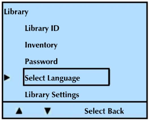
text_image
Library Library ID Inventory Password Select Language Library Settings Select Back- Press Select.
- Press Modify.
- Press or until the selection arrow () points to the desired language. Press Select.
The LCD displays the following screen (in this example, German is shown):
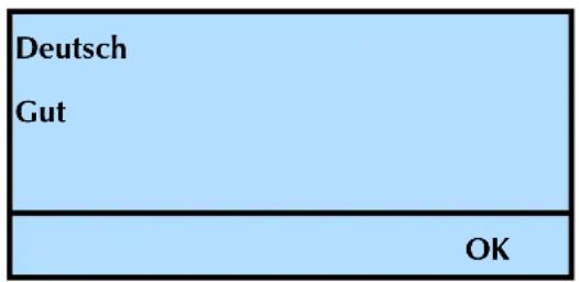
text_image
Deutsch Gut OK- Press OK.
- Press Back (as needed) to return to the Home screen.
CHANGING THE LCD SETTINGS
If desired, you can change the LCD's contrast from its default setting to a level that is appropriate for your lighting conditions.
To change the LCD settings:
- At the Home screen, press Lib.
If necessary, enter the operator panel password (see page 80).
- Press ▼ until the selection arrow (▶) points to Library Settings.
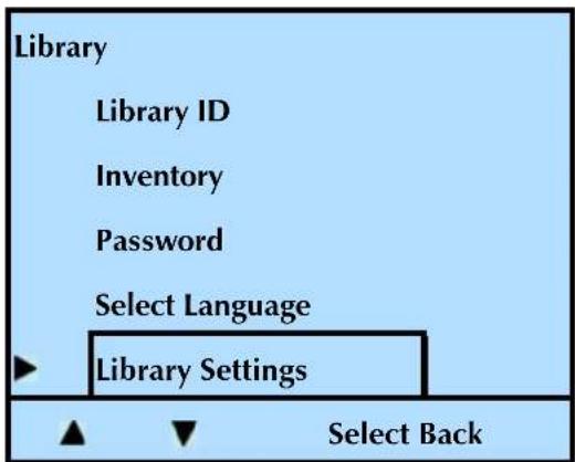
text_image
Library Library ID Inventory Password Select Language Library Settings Select Back-
Press Select.
-
Press ▼ until the selection arrow (▶) points to Display Settings.
-
Press Select.
Changing the Brightness
The brightness setting changes the brightness of the backlight. Follow steps 1 through 6 above, and continue with the following steps. See page 44 to change the contrast and page 45 to reverse the video (black background, and light text).
- Press ▼ until the selection arrow (▶) points to Display Brightness.
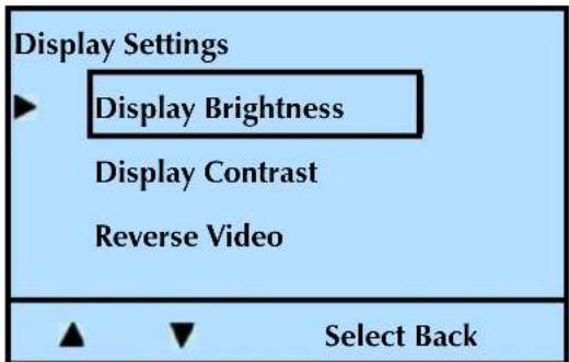
text_image
Display Settings ► Display Brightness Display Contrast Reverse Video ▲ ▼ Select Back-
Press Select.
-
Press Modify. Press + or - until the selection changes to the desired value.
As you change the value, the display will update to show the result of the current value.
- Press Select to accept the change, or Back to restore the previous value.
- Press OK to continue.
- Press Back (as needed) to return to the Home screen.
Changing the Contrast
The contrast setting changes the contrast of the Liquid Crystals. Too high a value will “wash out” the display, and too low a value will cause darkness and streaking.
To change the LCD contrast:
- At the Home screen, press Lib.
If necessary, enter the operator panel password (see page 80).
- Press ▼ until the selection arrow (▶) points to Library Settings.
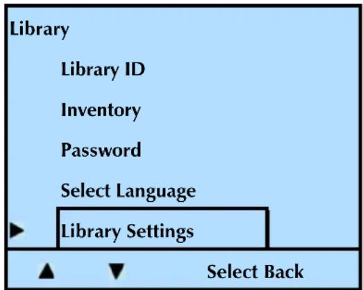
text_image
Library Library ID Inventory Password Select Language Library Settings Select Back- Press Select.
- Press ▼ until the selection arrow (▶) points to Display Settings.
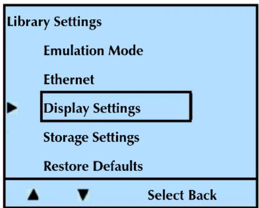
text_image
Library Settings Emulation Mode Ethernet ► Display Settings Storage Settings Restore Defaults ▲ ▼ Select Back-
Press Select.
-
Press ▼ until the selection arrow (▶) points to Display Contrast.
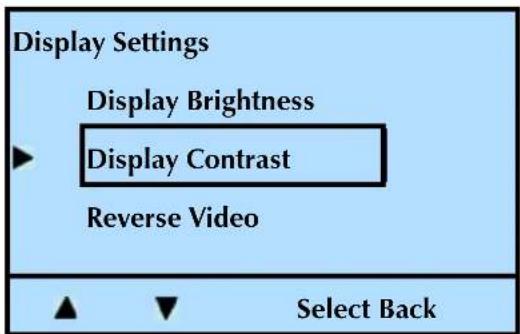
text_image
Display Settings Display Brightness ▶ Display Contrast Reverse Video ▲ ▼ Select Back- Press Select, and then Modify. Press + or - until the selection changes to the desired value.
As you change the value, the display will update to show the result of the current value. - Press Select to accept the change, or Back to restore the previous value.
- Press OK to continue.
- Press Back (as needed) to return to the Home screen.
Reversing the Video
You can reverse the video (make the background dark and the text light) by following these steps.
- At the Home screen, press Lib.
If necessary, enter the operator panel password (see page 80).
- Press ▼ until the selection arrow (▶) points to Library Settings.
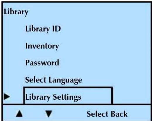
text_image
Library Library ID Inventory Password Select Language Library Settings Select Back-
Press Select.
-
Press ▼ until the selection arrow (▶) points to Display Settings.
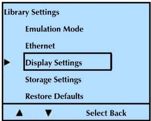
text_image
Library Settings Emulation Mode Ethernet ► Display Settings Storage Settings Restore Defaults ▲ ▼ Select Back-
Press Select.
-
Press ▼ until the selection arrow (▶) points to Reverse Video.
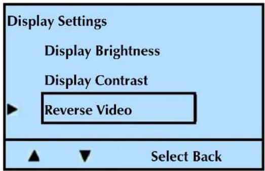
text_image
Display Settings Display Brightness Display Contrast Reverse Video Select Back- Press Select, and then Modify. Press + or - to toggle between Enable and Disable.
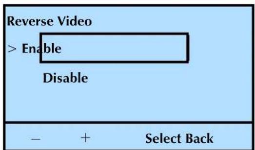
text_image
Reverse Video > Enable Disable - + Select Back- Press Select to accept the change, or Back to restore the previous value.
Once you enable the Reverse Video feature, the front panel looks like this:
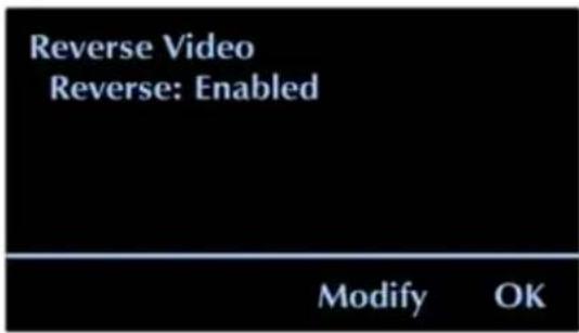
text_image
Reverse Video Reverse: Enabled Modify OK- Press OK to continue.
- Press Back (as needed) to return to the Home screen.
SETTING THE DATA CARTRIDGE SLOT COUNT
You can limit the number of slots visible to the SCSI interface for compatibility with backup software.
To change the visible number of slots:
- At the Home screen, press Lib.
If necessary, enter the operator panel password (see page 80).
- Press ▼ until the selection arrow (▶) points to Library Settings.
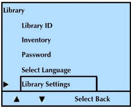
text_image
Library Library ID Inventory Password Select Language Library Settings Select Back-
Press Select.
-
Press ▼ until the selection arrow (▶) points to Storage Settings.
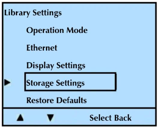
text_image
Library Settings Operation Mode Ethernet Display Settings Storage Settings Restore Defaults Select Back- Press Select.
- Press ▼ until the selection arrow (▶) points to Slot Count.
- Press Select.
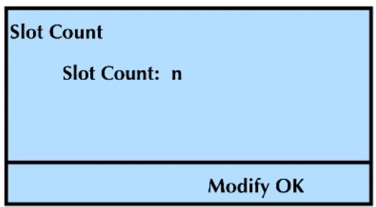
text_image
Slot Count Slot Count: n Modify OK- Press Modify. Press + or - until the selection changes to the desired value. Press Select.
- Press OK to continue.
- Press Back (as needed) to return to the Home screen.
! Important
You may need to reconfigure your backup application to recognize the new slot count. Refer to your application's documentation for instructions.
ENABLING AND DISABLING THE I/E PORT
The library ships from the factory with the I/E port enabled. Use these instructions to disable the I/E port, or to enable it if it was previously disabled.
Setting Description
Enabled Use the I/E port to import and export cartridges without removing an entire magazine
Disabled Gain one more cartridge storage slot/cell
! Important
Changing the I/E Port setting always disables the Fixed Cleaning Slot. If you wish to use the Fixed Cleaning Slot, it must be enabled after selecting the I/E Port Option.
See "Activating the Cleaning Cartridge Cell" on page 64 for additional information.
To enable or disable the I/E port:
- At the Home screen, press Lib.
If necessary, enter the operator panel password (see page 80).
- Press ▼ until the selection arrow (▶) points to Library Settings.
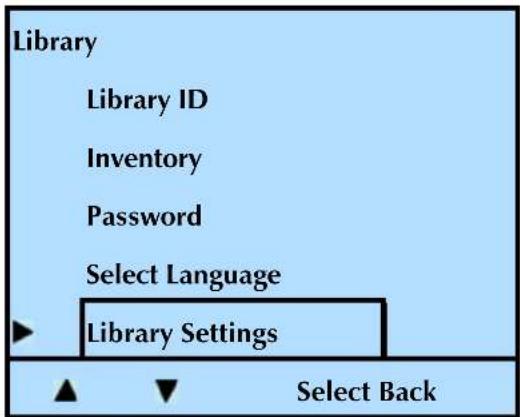
text_image
Library Library ID Inventory Password Select Language Library Settings Select Back-
Press Select.
-
Press ▼ until the selection arrow (▶) points to Storage Settings.
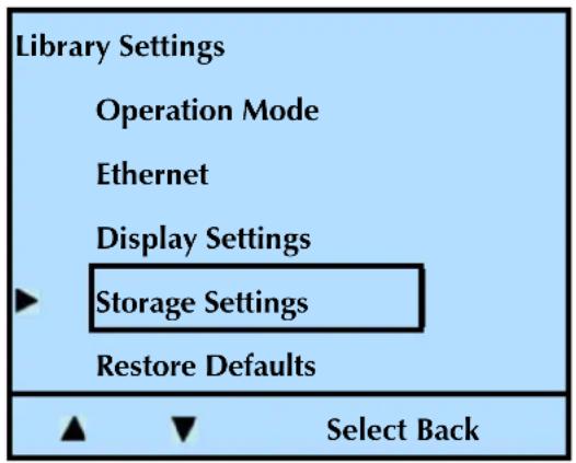
text_image
Library Settings Operation Mode Ethernet Display Settings Storage Settings Restore Defaults Select Back- Press Select.
- Press ▼ until the selection arrow (▶) points to I/E Port.
- Press Select, and then Modify.
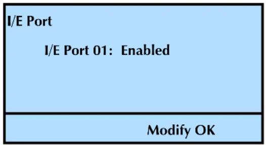
text_image
I/E Port I/E Port 01: Enabled Modify OK- Press + or - to toggle between Enable and Disable. Press Select.
Note: Enabling the I/E port allows you to use it to import and export cartridges. Disabling the I/E port allows you to use it as a storage slot.
- Press OK to continue.
- Press Back (as needed) to return to the Home screen.
ENABLING THE MEDIA IDENTIFIER
You can enable the library to identify the 'type' of media installed in the library when it scans barcodes. With this option enabled, the bar code scan includes two extra digits: L2 for an LTO-2 data cartridge or L3 for an LTO-3 data cartridge.
| Setting | The scan provides information similar to this... |
| Enabled | A000001L2 |
| Disabled | A000001 |
Note: The library scans the bar code label, not the cartridge. Ensure that you affix the correct label type to the cartridges: LTO-2 labels for LTO-2 cartridges, and LTO-3 labels for LTO-3 cartridges.
To enable or disable the media identifier:
- At the Home screen, press Lib.
If necessary, enter the operator panel password (see page 80).
- Press ▼ until the selection arrow (▶) points to Library Settings, and then press Select.
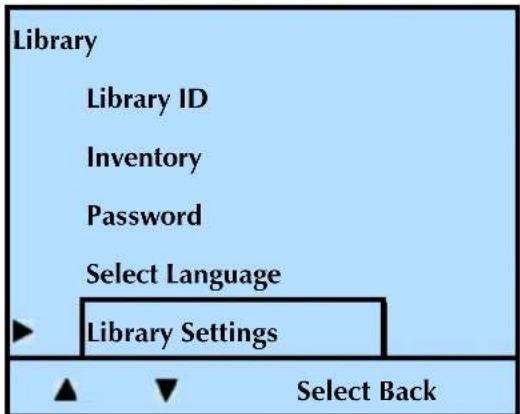
text_image
Library Library ID Inventory Password Select Language Library Settings Select Back- Press ▼ until the selection arrow (▶) points to Storage Settings.
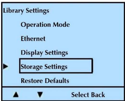
text_image
Library Settings Operation Mode Ethernet Display Settings Storage Settings Restore Defaults Select Back-
Press Select, and then press ▼ until the selection arrow (▶) points to Label Media Type, and then press Select.
-
Press Modify, and then press + or - to toggle between Enabled and Disabled.
Disabled
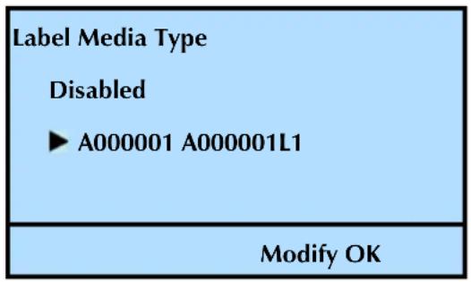
text_image
Label Media Type Disabled ► A000001 A000001L1 Modify OKEnabled
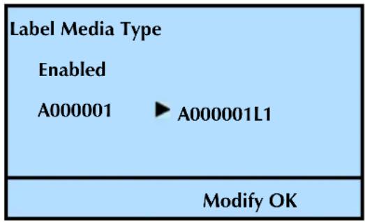
text_image
Label Media Type Enabled A000001 ▶ A000001L1 Modify OK- Press Select.
- Press OK to continue.
- Press Back (as needed) to return to the Home screen.
CHANGING THE SCSI IDs
Each device on a SCSI bus must have a unique SCSI ID so that it can be identified by the host computer. You can use the default IDs for the tape drive(s) or change them if they conflict with other devices on the SCSI bus.
Notes: The library communicates with the host through the SCSI interface of the tape drive(s) via the ADI serial interface. The SCSI interface as seen by the host is the SCSI interface of the tape drive.
See the tape drive Product Manual for tape drive information. See Automation/Drive Interface - Command (ADC) for ADI information.
If you change the tape drive's SCSI ID after the library has been in operation, you may need to reboot your host computer so that it recognizes the new ID.
To change the tape drive's SCSI ID:
- At the Home screen, press Drive.
If necessary, enter the operator panel password (see page 80).
- Press ▼ until the selection arrow (▶) points to Interface.
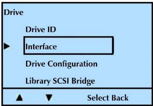
text_image
Drive Drive ID ► Interface Drive Configuration Library SCSI Bridge Select Back- Press Select.
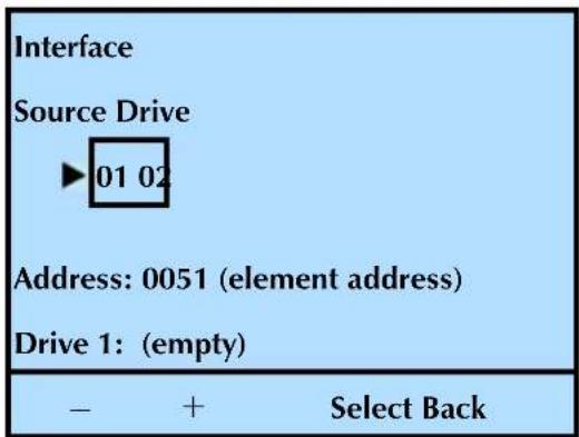
text_image
Interface Source Drive ►01 02 Address: 0051 (element address) Drive 1: (empty) - + Select Back- Press or to select the tape drive (if your library has more than one tape drive installed). Press Select to see the following screen.
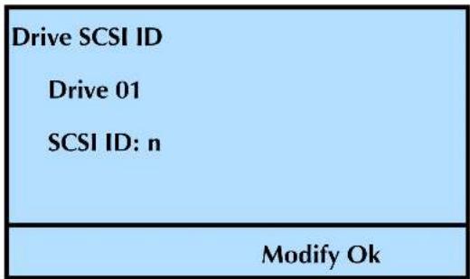
text_image
Drive SCSI ID Drive 01 SCSI ID: n Modify Ok- Press Modify. Press + or - until the selection changes to the desired value, and then press Select.
- Press OK.
- Press Back (as needed) to return to the Home screen.
TAPE DRIVE SCSI INTERFACE (LIBRARY BRIDGE)
If you have two tape drives installed in the library, you can assign one of them to act as the primary SCSI interface (bridge) for the library. If you have only one tape drive installed, it automatically acts as the SCSI bridge.
Note: The library communicates with the host through the SCSI interface of the tape drive(s) via the ADI serial interface. The SCSI interface as seen by the host is the SCSI interface of the tape drive.
See the tape drive Product Manual for tape drive information.
See Automation/Drive Interface - Command (ADC) for ADI information.
To assign the tape drive SCSI bridge:
- At the Home screen, press Drive.
If necessary, enter the operator panel password (see page 80).
- Press ▼ until the selection arrow (▶) points to Library SCSI Bridge.
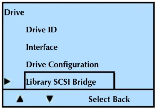
text_image
Drive Drive ID Interface Drive Configuration Library SCSI Bridge Select Back- Press Select.
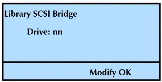
text_image
Library SCSI Bridge Drive: nn Modify OK- Press Modify. Press + or - to select the desired tape drive. Press Select.
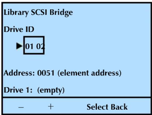
text_image
Library SCSI Bridge Drive ID ▶ 01 02 Address: 0051 (element address) Drive 1: (empty) - + Select BackThe following screen appears.
| Pending Action: |
| Library SCSI Bridge |
| Reset Will Occur! |
| Continue? |
| OK Back |
- Press OK to accept the change or back to cancel the change.
- Press Back (as needed) to return to the Home screen.
If you replace a tape drive, or add a second half-height tape drive to your library, you must set the tape drive configuration to match the tape drives that are installed in the library.
To set tape drive configuration:
- At the Home screen, press Drive.
If necessary, enter the operator panel password (see page 80).
- Press ▼ until the selection arrow (▶) points to Drive Configuration.
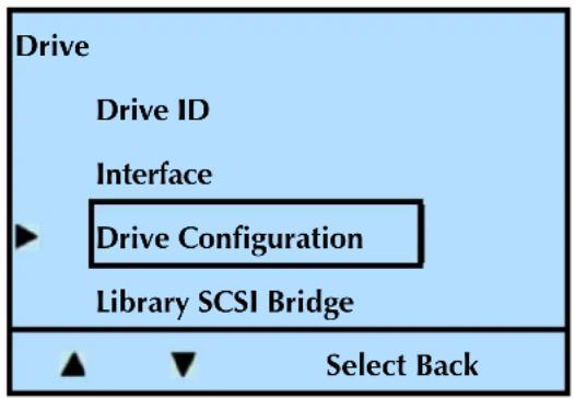
text_image
Drive Drive ID Interface ► Drive Configuration Library SCSI Bridge ▲ ▼ Select Back- Press Select.
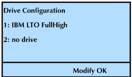
text_image
Drive Configuration 1: IBM LTO FullHigh 2: no drive Modify OKNote: The library lists “no drive” only if there is no room for more tape drives. For example, in the above screen, the library has one full height tape drive installed. The two tape drive number is for two half height tape drives.
- Press Modify. Press ▼ or ▲ until the selection arrow (▶) points to the desired configuration. Press Select.
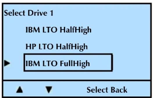
text_image
Select Drive 1 IBM LTO HalfHigh HP LTO HalfHigh IBM LTO FullHigh Select BackNotes: This menu option requires input for all of the tape drives installed in the library. If you press "Back" before configuring all the tape drives, the configuration selection will not change.
- Press OK. Repeat the process for each tape drive installed.
- Press Back (as needed) to return to the Home screen.
CHANGING THE EMULATION MODE
By default, the library operates in Native emulation mode and returns the product identification, "MAGNUM 224," in response to a SCSI INQUIRY command from an application. If your library software has not yet been certified for the StorageLibrary T24, you can select an option in Table 3-6, which lists the available emulation modes for the library.
Note: If you change the emulation mode, you will need to reboot your host computer so that it recognizes the new emulation mode.
Table 3-6 Emulation modes for the StorageLibrary T24
| Emulation Mode | Returns this Product Identification in response to an INQUIRY command |
| Native The default | Product Identification stored in the library's microcode. |
| Exabyte 221L “Exabyte_221L” where each “_” represents an ASCII space character. | |
| Exabyte EZ17 | “Exabyte EZ17____” where each “_” represents an ASCII space character. |
| Exabyte 210 | “EXB-210____” where each “_” represents an ASCII space character. |
Because most backup applications are certified for one or more of these libraries, changing the emulation mode may allow these applications to support the library.
To change the emulation mode:
- At the Home screen, press Lib.
If necessary, enter the operator panel password (see page 80).
- Press ▼ until the selection arrow (▶) points to Library Settings.
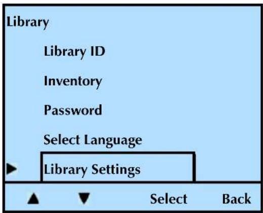
text_image
Library Library ID Inventory Password Select Language Library Settings Select Back- Press Select, and then press ▼ until the selection arrow (▶) points to Operation Mode.
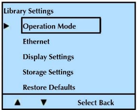
text_image
Library Settings ► Operation Mode Ethernet Display Settings Storage Settings Restore Defaults ▲ ▼ Select Back- Press Select, and then press ▼ until the selection arrow (▶) points to Emulation Mode.
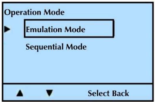
flowchart
graph TD
    A["Operation Mode"] --> B["Emulation Mode"]
    B --> C["Sequential Mode"]
    C --> D["Select Back"]
- Press Select, and then press Modify.
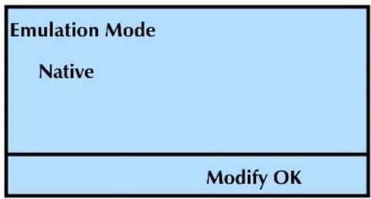
text_image
Emulation Mode Native Modify OK- Press until the selection arrow () points to the desired mode, and then press Select.
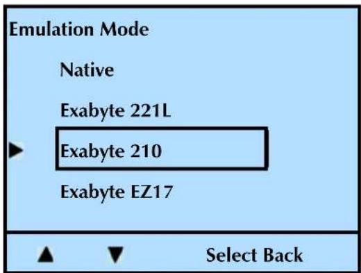
text_image
Emulation Mode Native Exabyte 221L Exabyte 210 Exabyte EZ17 Select BackThe LCD displays the following screen:
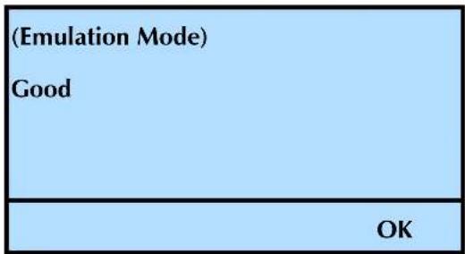
text_image
(Emulation Mode) Good OK-
Press OK.
-
Press Back (as needed) to return to the Home screen.
SETTING THE LIBRARY TO OPERATE IN SEQUENTIAL MODE
The operation mode determines how the library processes cartridges. The library will operate using one of these two options.
- Random–The library processes cartridges according to commands issued from an application.
Sequential–The library processes cartridges sequentially without direction from an application.
In Sequential mode, magazines are automatically associated with tape drives so that each tape drive and its associated magazine (or magazines) becomes an independent autoloader.
! Important
If you are using a backup application which is capable of controlling the library, do not configure the library to operate in Sequential mode.
Random is the default operating mode for the library. To change the operating mode to Sequential, you need to enable the Sequential Mode, and set the Restart and Loop options.
- At the Home screen, press Lib.
If necessary, enter the operator panel password (see page 80).
- Press ▼ until the selection arrow (▶) points to Library Settings.
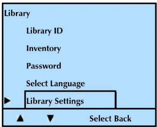
text_image
Library Library ID Inventory Password Select Language Library Settings Select Back-
Press Select.
-
Press ▼ until the selection arrow (▶) points to Operation Mode.
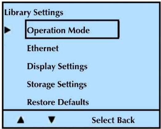
text_image
Library Settings ► Operation Mode Ethernet Display Settings Storage Settings Restore Defaults ▲ ▼ Select Back- Press Select. Press ▼ until the selection arrow (▶) points to Sequential Mode, and press Select.
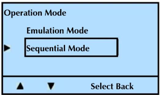
flowchart
graph TD
    A["Operation Mode"] --> B["Emulation Mode"]
    B --> C["Sequential Mode"]
    C --> D["Select Back"]
Enabling Sequential Mode
! Important
If you are using a backup application which is capable of controlling the library, do not configure the library to operate in Sequential mode.
a. Press Modify.
| Sequential Mode | ||
| Sequential : Mode | ||
| Restart | : Mode | |
| Loop | : Mode | |
| Modify | OK | |
b. At the first screen (Sequential), press + or - to select Enable.
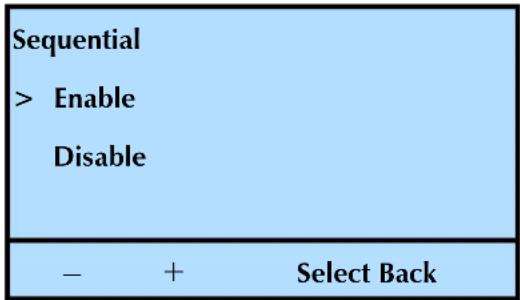
text_image
Sequential > Enable Disable - + Select Backc. Press Select, and then continue with Setting the Restart Option.
Setting the Restart Option
The Restart option determines what the library does after it is reset, power cycled, or when a magazine has been re-inserted.
Setting The library...
Enabled restarts at the beginning of the cartridge sequence
Disabled resume where it left off when the interruption occurred
a. At the Restart screen, press + or - to select Enable or Disable.
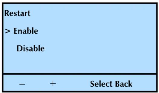
text_image
Restart > Enable Disable - + Select Backb. Press Select, and then continue with Setting the Loop Option.
Setting the Loop Option
The Loop option determines what the library does after it has finished processing the last cartridge in the sequence.
Setting The library...
Enabled loops back to the first cartridge in the sequence and begins processing the cartridges again
Disabled stops and waits for operator intervention. You need to set the library to operate in Random mode, and then reset it to Sequential mode
a. At the Loop screen, press + or - to select Enable or Disable.
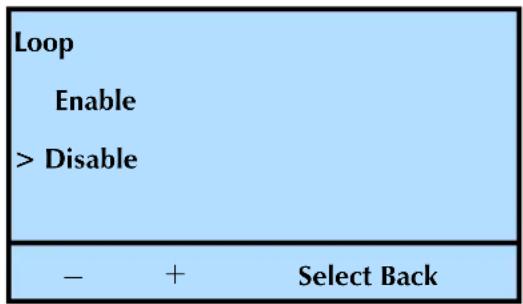
text_image
Loop Enable > Disable - + Select Backb. Press Select.
-
Press OK.
-
Press Back (as needed) to return to the Home screen.
The Home screen now indicates that the library is operating in Sequential Mode by the following changes.
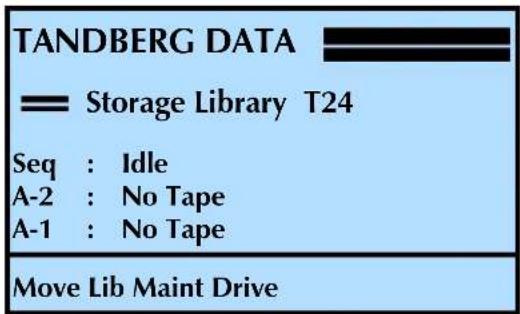
text_image
TANDBERG DATA Storage Library T24 Seq : Idle A-2 : No Tape A-1 : No Tape Move Lib Maint DriveLib (Library) is replaced with Seq (Sequential).
D-1 (Drive-1) and D-2 (Drive-2) are replaced with A-1 and A-2 (indicating autoload function).
SETTING UP AUTOMATIC TAPE DRIVE CLEANING
The Autoclean option enables the library to automatically perform tape drive cleaning without operator intervention. When Autoclean is enabled, the library monitors the cleaning requirements of the tape drive(s). When a tape drive indicates it needs cleaning, the library loads the cleaning cartridge into the tape drive. After the cleaning cycle is complete, the tape drive unloads and ejects the cleaning cartridge, and the library resumes operation.
! Important
If you plan to use automatic cleaning, the cleaning cartridge should be stored in:
- Slot/Cell 2—if the I/E Port is enabled
- Slot/Cell 1—if the I/E Port is disabled
If your backup application has a cleaning option, be sure to turn that option OFF.
Note: You do not have to use the library's Autoclean option to clean the tape drive(s). You can choose from several other cleaning methods, including using your backup application's cleaning function and using commands available through the operator panel. See page 132 for information about these cleaning alternatives.
Setting up automatic tape drive cleaning involves two procedures:
▶ Activating the cleaning cartridge cell
Enabling the Autoclean option
Activating the Cleaning Cartridge Cell
Activating the cleaning cartridge cell designates the storage location for a cleaning cartridge. Use one of the following options:
▶ Slot/Cell 2—if the I/E Port is enabled
▶ Slot/Cell 1—if the bottom I/E Port is disabled
Note: The library ships from the factory with the I/E Port enabled. In order to use that slot/cell as the fixed cleaning slot, you need to disable it. See “Enabling and Disabling the I/E Port” on page 49.
To activate the cleaning cartridge cell:
- At the Home screen, press Maint.
If necessary, enter the operator panel password (see page 80).
- Press ▼ until the selection arrow (▶) points to Cleaning Options.
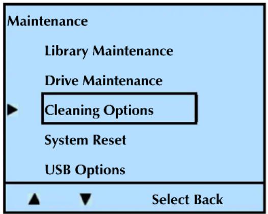
text_image
Maintenance Library Maintenance Drive Maintenance Cleaning Options System Reset USB Options Select Back-
Press Select.
-
Press ▲ or ▼ until the selection arrow (▶) points to Fixed Cleaning Slot.
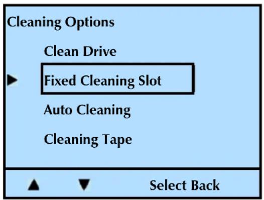
text_image
Cleaning Options Clean Drive Fixed Cleaning Slot Auto Cleaning Cleaning Tape Select Back5. Press Select.
| Fixed Cleaning Slot |
| Fixed Cleaning Slot |
| Slot 2: |
| Disabled |
| Modify OK |
6. Press Modify.
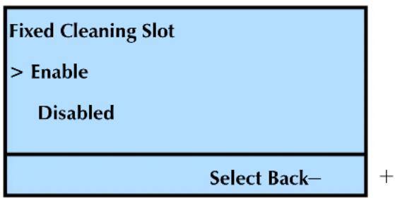
flowchart
graph TD
    A["Fixed Cleaning Slot"] --> B["> Enable"]
    B --> C["Disabled"]
    D["Select Back-"] --> E["+"]
- Press + or - until the selection arrow (▶) points to Enable, and then press Select.
- Press Back (as needed) to return to the Home screen.
Enabling the Autoclean Option
After enabling the fixed cleaning slot, you can turn on automatic tape drive cleaning by enabling the Autoclean option.
To enable the AutoClean option:
- At the Home screen, press Maint.
If necessary, enter the operator panel password (see page 80).
- Press ▼ until the selection arrow (▶) points to Cleaning Options.
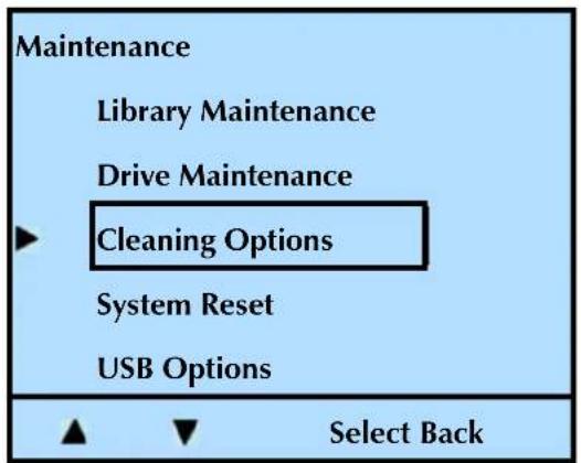
text_image
Maintenance Library Maintenance Drive Maintenance Cleaning Options System Reset USB Options Select Back- Press Select, and then press ▲ or ▼ until the selection arrow (▶) points to Auto Cleaning.
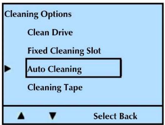
text_image
Cleaning Options Clean Drive Fixed Cleaning Slot Auto Cleaning Cleaning Tape Select Back- Press Select.
Note: The Fixed Cleaning Slot must be enabled prior to enabling the Auto Cleaning option.
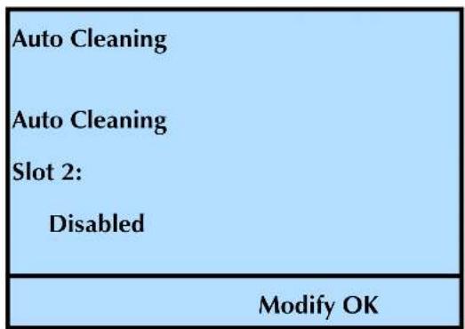
text_image
Auto Cleaning Auto Cleaning Slot 2: Disabled Modify OK- Press + or - until the selection arrow (▶) points to Enable, and then press Select.
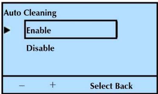
text_image
Auto Cleaning Enable Disable - + Select Back-
Press OK.
-
Press Back (as needed) to return to the Home screen.
SETTING ETHERNET CONFIGURATION OPTIONS
Table 3-7 Ethernet configuration options
| Remote Management Utility | The Remote Management utility allows you to connect to the library's Ethernet interface to remotely monitor operations, upgrade firmware, and create diagnostic listings. See: · Connecting the library to Ethernet—page 21 · Using the Remote Management utility—Chapter 4 |
| Ethernet Configuring the library's Ethernet interface typically involves specifying the library's IP address, subnet mask, and gateway address.·IP address—Used to route information from the library to the server. You can choose between dynamic (server-assigned) or static (user-assigned) addressing for the IP address.·Subnet Mask—Used to route information to designated devices within the network.·Gateway address—Allows information to be routed outside the subnet.·MAC address—Displays the Media Access Control address for the library. | |
| Network Addresses | This allows you to select the method used to set the Internet Protocol (IP) address for the library, as follows:·Static—The library uses a fixed IP Address, which is assigned in the IP Address option.·DHCP—The library uses an IP address assigned by the network DHCP (Dynamic Host Configuration Protocol) server. This is the default setting for the library (DHCP enabled). |
| SNMP If you are | using a network-based monitor/management application other than the library's Remote Management utility, you may need to identify the library's Simple Network Management Protocol (SNMP) settings to the application. These settings include:Read community stringWrite community stringBroadcast community stringTrap addressTrap portYou can view and change these settings only through the library's Remote Management utility. See Chapter 4 for instructions. |
| FTP Interface The | the library also includes an FTP interface that you can use to transfer firmware files or create diagnostic listings. You can:Set up an FTP user name and password for this interface or use the library's defaultsView and change the FTP settings only through the library's Remote Management utilityFor instructions, see Chapter 4.For information about accessing the library's FTP interface and using an FTP utility to upgrade firmware or obtain diagnostic listings, see page 190. |
Enabling Network Addressing and Setting the Ethernet Addresses
To enable or disable Network addressing:
- At the Home screen, press Lib.
If necessary, enter the operator panel password (see page 80).
- Press ▼ until the selection arrow (▶) points to Library Settings.
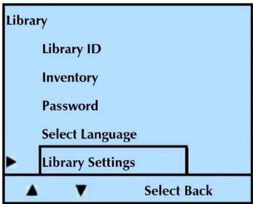
text_image
Library Library ID Inventory Password Select Language Library Settings Select Back-
Press Select.
-
Press ▼ until the selection arrow (▶) points to Ethernet.
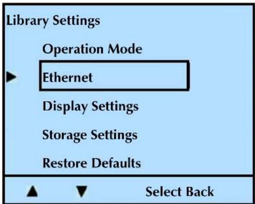
text_image
Library Settings Operation Mode Ethernet Display Settings Storage Settings Restore Defaults Select Back- Press Select.
Changing the DHCP setting
The default setting for the library is DHCP enabled.
- To change the DHCP setting, press on ▲ until ▼ the selection arrow ( ) points to DHCP.

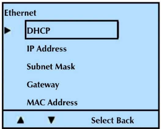
text_image
Ethernet DHCP IP Address Subnet Mask Gateway MAC Address Select Back- Press Select.
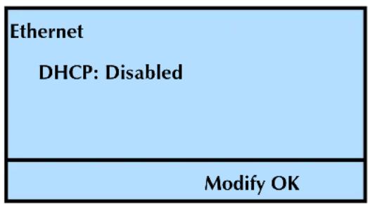
text_image
Ethernet DHCP: Disabled Modify OK- Press Modify. Press + or - to toggle between Enable and Disable.
Disabling DHCP addressing (assigned by the server) enables Static addressing (a fixed IP address).
! Important
Dynamic assignment of the library's IP address may require periodic reinstallation or reconfiguration of some monitoring software applications.
-
Press Select.
-
Press OK.
Changing the IP Address
- To change the IP address, press until the selection arrow () points to IP Address.
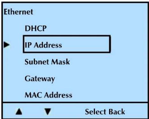
text_image
Ethernet DHCP IP Address Subnet Mask Gateway MAC Address Select Back- Press Select.

text_image
Ethernet IP Address: 000.000.000.000 Modify OK- Press Modify. Press + to increase the value.
Note: Press the + to cycle through all the number choices.
- Press to move to the next number.
Repeat steps 4 and 5 to change the remaining values in the address.
-
Press Done.
-
Press OK.
Changing the Subnet Mask
- To change the Subnet Mask address, press until the selection arrow () points to Subnet Mask.
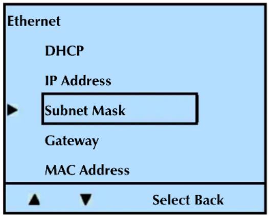
text_image
Ethernet DHCP IP Address Subnet Mask Gateway MAC Address Select Back- Press Select.
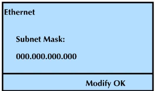
text_image
Ethernet Subnet Mask: 000.000.000.000 Modify OK- Press Modify. Press + to increase the value.
Note: Press the + to cycle through all the number choices.
- Press to move to the next number.
Repeat steps 4 and 5 to change the remaining values in the address.
-
Press Done.
-
Press OK.
Changing the Gateway Address
- To change the Gateway address, press until the selection arrow ( ) points to Gateway.
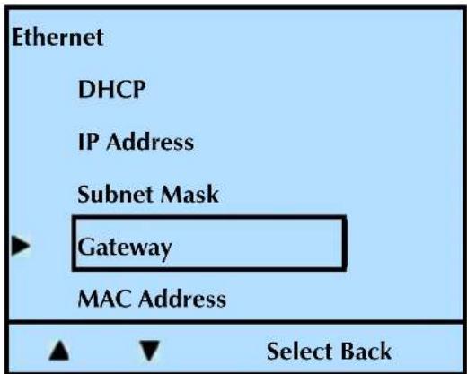
text_image
Ethernet DHCP IP Address Subnet Mask Gateway MAC Address Select Back- Press Select.
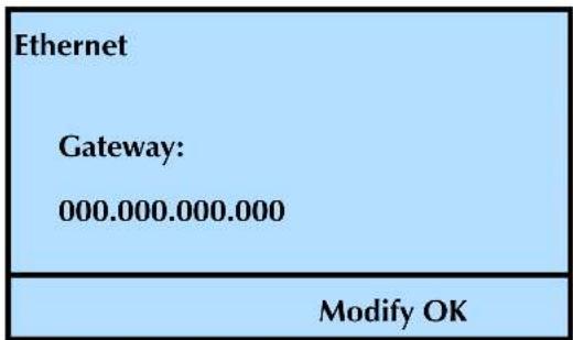
text_image
Ethernet Gateway: 000.000.000.000 Modify OK- Press Modify. Press + to increase the value.
Note: Press the + to cycle through all the number choices.
- Press to move to the next number.
Repeat steps 4 and 5 to change the remaining values in the address.
-
Press Done.
-
Press OK.
-
Press Back (as needed) to return to the Home screen.
Viewing the MAC Address
- To view the MAC address, press until the selection arrow () points to MAC Address.
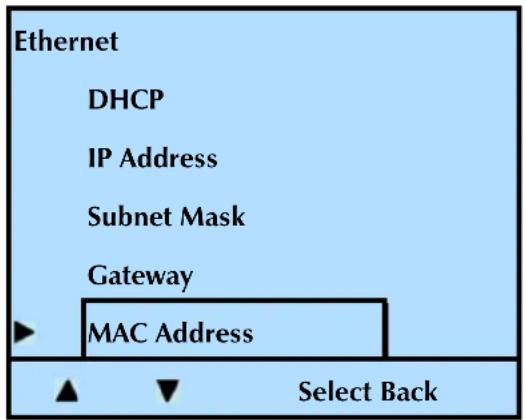
text_image
Ethernet DHCP IP Address Subnet Mask Gateway MAC Address Select Back- Press Select.
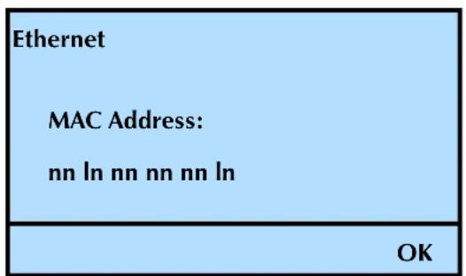
text_image
Ethernet MAC Address: nn ln nn nn nn ln OK- Press OK.
- Press Back (as needed) to return to the Home screen.
SETTING USB OPTIONS
You can use the library's USB to share the user selectable configurations between libraries. Also see "USB Port—Library Firmware Upgrade and Diagnostics" on page 193 and "USB Port—Tape Drive Firmware Upgrade" on page 196.
To share the configuration settings between libraries, you need to perform these two steps:
Save configuration to USB —The library writes data to the file shown (CAL3CLON.BIN) that contains the user selectable configuration values (SCSI IDs, I/E Port Enable, Cleaning Cartridge Information, SCSI element addresses, emulation mode, language, password, saved Mode Select data, drive configuration, and so forth).
Get configuration from USB — Use this option to "clone" the user selectable configurations from a different library. Use this in conjunction with the "Save configuration from USB" option.
The library reads data from the file shown (CAL3CLON.BIN) that contains the user selectable configuration values (SCSI IDs, I/E Port Enable, Cleaning Cartridge Information, SCSI element addresses, emulation mode, language, password, saved Mode Select data, drive configuration, and so forth).
The library then saves those settings to its own non-volatile RAM so that it "clone's" the device which stored the data. The user selected option will be identical to that original machine.
Saving Configurations
To Save the Configurations to load into a different library:
- At the Home screen, press Maint.
If necessary, enter the operator panel password (see page 80).
- Press ▼ until the selection arrow (▶) points to USB Options.
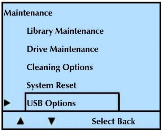
text_image
Maintenance Library Maintenance Drive Maintenance Cleaning Options System Reset USB Options Select Back-
Press Select.
-
Press ▲ or ▼ until the selection arrow (▶) points to Save Configuration.
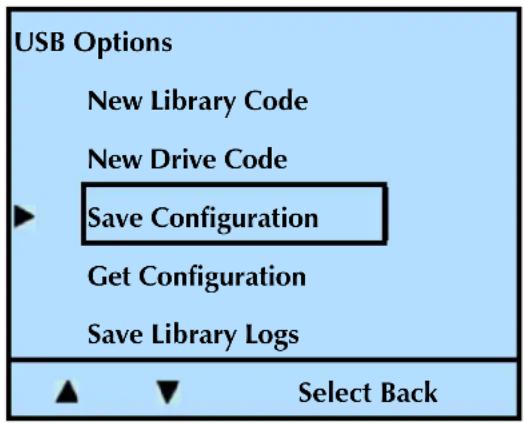
text_image
USB Options New Library Code New Drive Code Save Configuration Get Configuration Save Library Logs Select Back- Press Select.
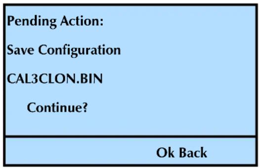
text_image
Pending Action: Save Configuration CAL3CLON.BIN Continue? Ok Back- Press OK to continue with the action, or Back to cancel the action.
- Press Back (as needed) to return to the Home screen.
Getting Configurations
To Get the Configurations from a different library:
- At the Home screen, press Maint.
If necessary, enter the operator panel password (see page 80).
- Press ▼ until the selection arrow (▶) points to USB Options.
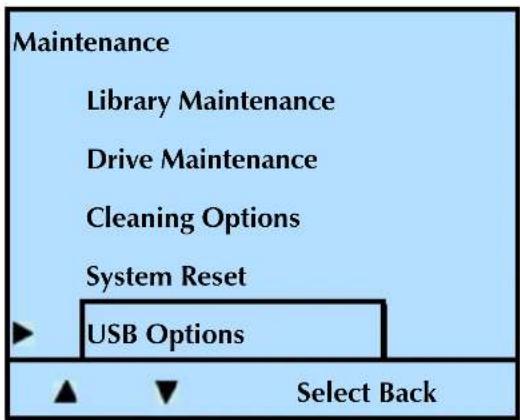
text_image
Maintenance Library Maintenance Drive Maintenance Cleaning Options System Reset USB Options Select Back-
Press Select.
-
Press ▲ or ▼ until the selection arrow (▶) points to Get Configuration.
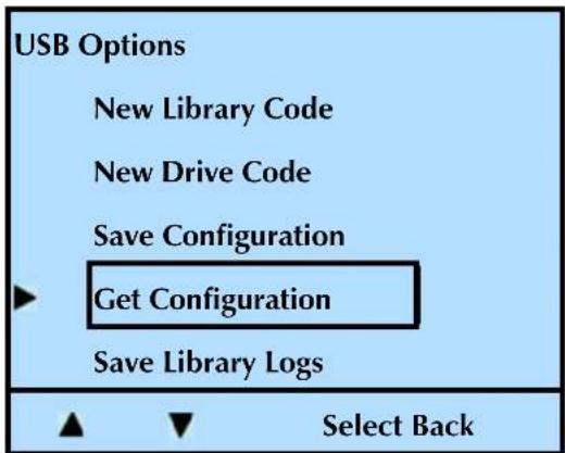
text_image
USB Options New Library Code New Drive Code Save Configuration Get Configuration Save Library Logs Select Back- Press Select.
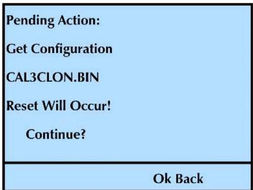
text_image
Pending Action: Get Configuration CAL3CLON.BIN Reset Will Occur! Continue? Ok Back-
Press OK to continue with the action (and reset the library), or Back to cancel the action.
-
Press Back (as needed) to return to the Home screen.
SETTING UP LIBRARY PASSWORD PROTECTION
To prevent unauthorized users from disrupting library operation, you can set up a password for accessing operator panel menus. When you enable the password, all operator panel functions are prevented. When you press any of the main menu buttons (Move, Lib, Maint, or Drive), the library prompts you for the password.
Note: If you are using the library's Remote Management utility (see Chapter 4), you can set up a separate password to prevent unauthorized users from using the utility to access the library's configuration settings.
If you forget the password, see "Getting your password hint" on page 82.
Setting up an operator panel password
To set up a password for the operator panel:
- At the Home screen, press Lib.
If necessary, enter the operator panel password (see page 80).
- Press ▼ until the selection arrow (▶) points to Password.
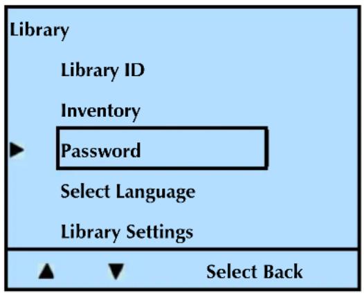
text_image
Library Library ID Inventory Password Select Language Library Settings ▲ ▼ Select Back- Press Select.
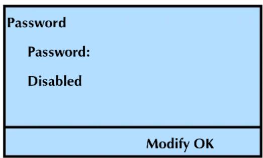
text_image
Password Password: Disabled Modify OK- Press Modify. Press + or - to switch between Enable and Disable.
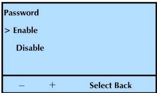
text_image
Password > Enable Disable - + Select Back- With the arrow pointed to Enable, press Select.
Note: The password can be between 3 and 11 characters long and consists of upper case alphabet letters ("A" to "Z"), lower case alphabet letters ("a" to "z"), and numbers ("0" to "9").
Characters increment as follows:
| First (upper case letters) | Second (lower case letters) | Third (numbers) | Last (blank space) (if the cursor is beyond the third character) |
| “A” to “Z” | “a” to “z” | “0” to “9” | “” |
The blank allows you to truncate the password at the current letter and will remove all characters beyond that point. If you continue to press" 4, the characters will begin again at "A" (upper case A).
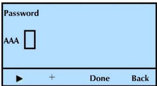
text_image
Password AAA ▶ + Done Back-
Press to increase the letter (the library starts at "A").
-
Press () ▶ move to the next field and repeat step 8.
Pressing the (▶) button scrolls the cursor through the current letters of the password, including an extra "blank" character at the end, which allows you to add to the length of the password. Scrolling beyond the end of the password causes the cursor to wrap to the first character of the password.
This screen shows an example of a password using upper and lower case letters and numbers.
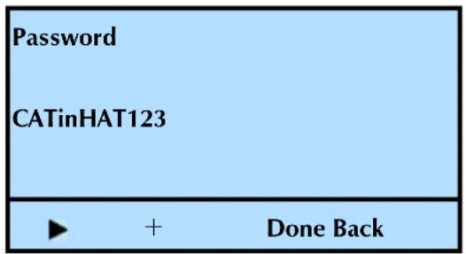
text_image
Password CATinHAT123 ► + Done Back- Press Done to accept the change, or press Back to reject the change.
Once you enable the password, a padlock icon appears in the upper right screen to show that the operator panel is password protected.
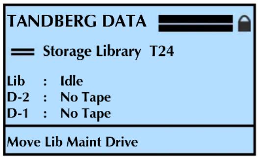
text_image
TANDBERG DATA = Storage Library T24 Lib : Idle D-2 : No Tape D-1 : No Tape Move Lib Maint Drive- Press Back (as needed) to return to the Home screen.
When password protection is in effect, you must enter the password before you can use the operator panel menus. Each time you return to the Home screen and press a different button, password protection is re-activated; you must enter the password again to access the menus.
Accessing password protected operator panel menus
If you need to gain access to the operator panel menus, but want password protection to remain in effect, follow these steps:
- At the Home screen, press the mode you need to access. The following screen appears.
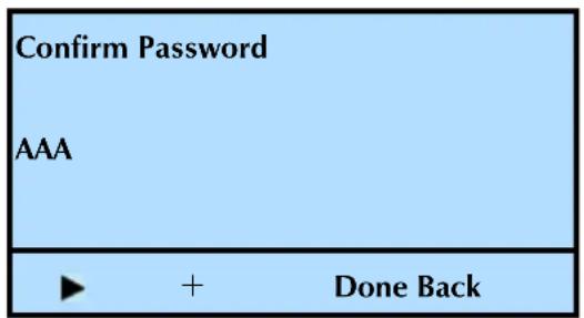
text_image
Confirm Password AAA ► + Done Back-
Enter the operator panel password by following the steps on page 79. If you forget your password, see "Getting your password hint" on page 82.
-
Press Done. If you entered the correct password, the library displays the screen you requested.
Disabling the operator panel password
To turn off password protection for the operator panel:
- At the Home screen, press Lib.
-
Enter the operator panel password (see page 80). If you forget your password, see "Getting your password hint" on page 82.
-
Press ▼ until the selection arrow (▶) points to Password.
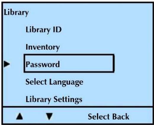
text_image
Library Library ID Inventory Password Select Language Library Settings Select Back- Press Select.
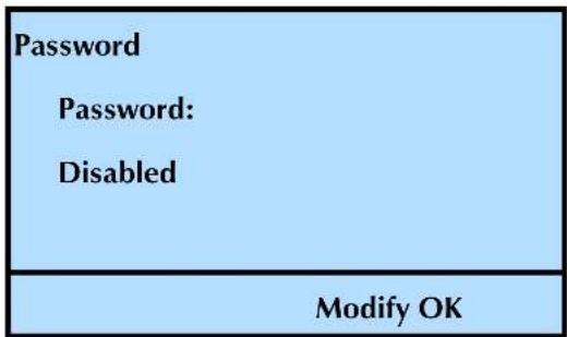
text_image
Password Password: Disabled Modify OK- Press Modify. Press + or - to switch between Enable and Disable.
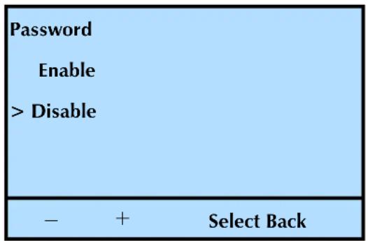
text_image
Password Enable > Disable - + Select Back- With the arrow pointed to Disable, press Select.
- Press OK.
- Press Back (as needed) to return to the Home screen.
Getting your password hint
In case you forget your password, you can get a password hint. Once you get the hint, contact Technical Support and give them the hint. They will provide the password.
When you try to access any screen, and the password is enabled, the library will prompt you to enter the password. From this point, follow these steps:
- Hit the Back button, and the following screen appears:
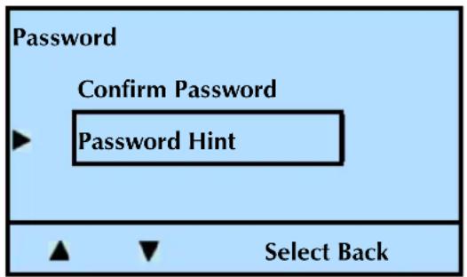
flowchart
graph TD
    A["Password"] --> B["Confirm Password"]
    B --> C["Password Hint"]
    C --> D["Select Back"]
-
Press ▼ until the selection arrow (▶) points to Password Hint.
-
Press Select.
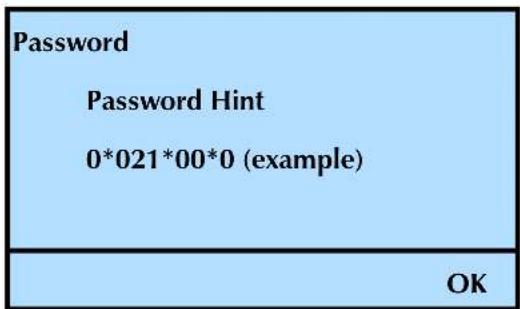
text_image
Password Password Hint 0*021*00*0 (example) OK- Copy down the password hint and contact Tandberg Data Technical Support (see www/tandbergdata.com). They will provide you with your password.
RESTORING THE DEFAULT CONFIGURATION
If necessary you can return all of the library configuration settings to their default values.
! Important When you use this option all changes that you previously made to any of the library's configuration settings are lost.
To restore the default configuration values:
- At the Home screen, press Lib.
If necessary, enter the operator panel password (see page 80).
- Press ▼ until the selection arrow (▶) points to Library Settings.
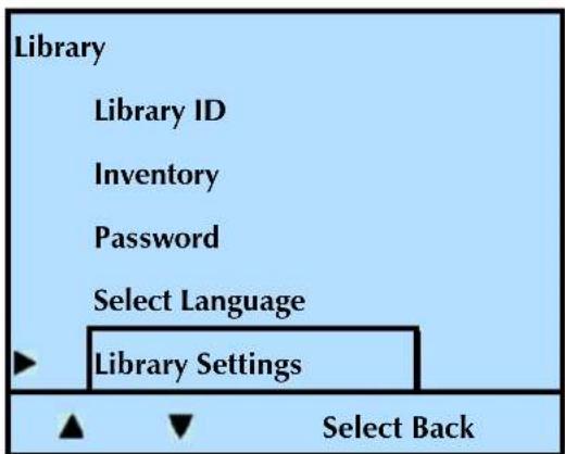
text_image
Library Library ID Inventory Password Select Language Library Settings Select Back-
Press Select.
-
Press ▼ until the selection arrow (▶) points to Restore Defaults.
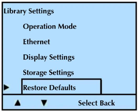
text_image
Library Settings Operation Mode Ethernet Display Settings Storage Settings Restore Defaults Select Back- Press Select. The following screen appears.

text_image
Pending Action: Restore Defaults Reset Will Occur! Continue? OK BackNote: This action will reset the library, which will re-boot the system.
- Press OK to reset the library, or Back to cancel the action.
After approximately five seconds, the library resets itself.
CHECKING THE SETUP
After configuring the library, check the setup by performing the exercises suggested below. While these exercises are not required, it is a good idea to verify that your software and hardware are properly communicating before you begin operation.
Import several cartridges into the library, and load and unload cartridges into the tape drive or tape drives (see page 129).
▶ Run a system demo (see page 188).
If you have not already done so, install the backup application on the host computer. Instruct the software to load and unload one or more cartridges in the tape drive(s). This helps determine whether the software and library are communicating properly.
Back up several megabytes of data with the tape drive(s) and perform a comparison check on the backed-up data. This determines whether the software and tape drive are communicating properly.
If the library and tape drive are not operating as expected:
▶ See Chapter 8 for troubleshooting tips
▶ See Appendix E for error message descriptions
If you cannot resolve the problem yourself, contact Tandberg Data Technical Support (see page iii).
NOTES
4
USING THE REMOTE
MANAGEMENT UTILITY
The library's Remote Management utility allows you to set configuration options, view library and tape drive information, and monitor operation across an Ethernet network. You can access the Remote Management utility using a standard web browser.
NOTICE–The functions described in this chapter are subject to change.
This chapter explains how to access the Remote Management utility and describes the configuration options and information available through the utility. If you plan to use the utility, refer to this chapter in conjunction with Chapter 3 – Configuring the Library.
| To view this information... go to... | ||
| Home Page | Viewing the Home page | page 88 |
| Configuration | Setting Configuration options | page 96 |
| Statistics | Viewing information on the Statistics page | page 105 |
| Tools | Using the Utility’s Tools | page 107 |
ACCESSING THE REMOTE MANAGEMENT UTILITY
To access the library's Remote Management utility:
- Connect the library to your Ethernet network as described on page 21.
- If not already powered on, power on the library as described on page 23.
- Use the library's operator panel to set up the Ethernet interface as described on page 67. Make a note of the library's IP address.
Note: If you set DHCP on, you can view the current server-assigned IP address for the library through the Status menu (see page 141).
- Launch your web browser and enter the library's IP address in the following format: http://IP address
5. Press Enter. The utility's Home page appears.
TANDBERG DATA Securing your Information

STORAGELIBRARY T24
| Home |
| Info |
| Status |
| Inventory |
| Configure |
| Statistics |
| Tools |
Library Information
| Device | Vendor | Product | Serial Number | Firmware Rev | SCSI ID:LUN |
| Library | EXABYTE | MAGNUM 224 | 000089001408 | C211 | 3:1 |
| Drive | IBM | ULTRIUM-TD3 | 1200019510 | 6BA0 | 3:0 |
Click here for web pages in English
Figure 4-1 Remote Management Utility–Home page
Notes:
Navigation tip – To help you more easily navigate, the screen that you are currently viewing is indicated by italics. For example, in Figure 4-1, both the Home and Info text is in italic font.
Quick links – You can click on these links from any page for quick access to the following:
| Click this Link... for quick access to this location... | |
| Home, Configure, Statistics, and Tools | Library and tape drive options and information |
| Tandberg Data Logo | Tandberg Data's web site atwww.tandbergdata.com |
| Product name(StorageLibrary T24) | The utility's Home screen page |
Magazine configuration – The left magazine is optional. The library is shipped with the right magazine installed and a "blank" installed in the left magazine's location. Contact your supplier to purchase additional magazines.
Tape drive configuration – You can configure your library for the following tape drive configuration options:
One half-height LTO-2 or LTO-3 tape drive Two half-height LTO-2 or LTO-3 tape drives One full-height LTO-3 tape drive
VIEWING THE HOME PAGE
This is the "home page" for the utility. The Home page provides information in four sections. See Figure 4-1 to view the Home page.
▶ Library Information (Home/Info) – shown in Figure 4-1
Library Status (Home/Status) – shown in Figure 4-2
▶ Tape Drive Status (Home/Status) – shown in Figure 4-2
- Inventory (Home/Inventory) – shown in Figure 4-4
LIBRARY INFORMATION PAGE-SCSI CONFIGURATION
Library Information
| Device | Vendor | Product | Serial Number | Firmware Rev | SCSI ID:LUN |
| Library | EXABYTE | MAGNUM 224 | 000089001408 | C211 | 3:1 |
| Drive | IBM | ULTRIUM-TD3 | 1200019510 | 68A0 | 3:0 |
The library information page (the Home page) provides this information:
Device This shows the library and tape drive or tape drives installed (the above screen shows one Hewlett Packard LTO-2 tape drive installed). The StorageLibrary T24 is configured for:
One or two LTO-2 half height (HH) tape drive(s)
One or two LTO-3 half height (HH) tape drive(s)
One LTO-3 full height (FH) tape drive
Vendor This shows the manufacturer of the product.
Product This shows the identification for the library and tape drive(s).
Serial Number This lists the serial numbers of the individual devices.
Firmware Revision This shows the firmware revision of each device installed – the library and tape drive(s).
SCSI ID:LUN This shows the SCSI ID for the tape drive(s) and the library.
LIBRARY INFORMATION PAGE-FIBRE CHANNEL CONFIGURATION
| Home |
| Info |
| Status |
| Inventory |
| Configure |
| Statistics |
| Tools |
Library Information
| Device | Vendor | Product | Serial Number | Firmware Rev | WWNN |
| Library | EXABYTE | MAGNUM 224 | 000089000349 | C211 | 200100D08051af0d |
| Drive | IBM | ULTRIUM-TD3 | 1200019610 | 6BA0 | 5005076312008033 |
WWNN World-Wide Node Name. This shows the number for the WWNN, which is the unique identifier of the device in a Fibre Channel network environment.
Notes: The library communicates with the host through the SCSI interface of the tape drive(s) via the ADI serial interface.
The SCSI interface as seen by the host is the SCSI interface of the tape drive. The library appears as LUN 1 on the same SCSI ID as the tape drive.
For additional information, see:
The tape drive's Product Manual for tape drive information.
Automation/Drive Interface - Command (ADC) for ADI information.
LIBRARY AND TAPE DRIVE STATUS PAGE
At the bottom of the Status page is an Update button that refreshes the information on the page. An option for automatically refreshing the page is also available. Check this option to have the information refreshed approximately every 6 seconds.
The information available on the Status page is shown in the following figure and described below.

Library Status
| Item | Status |
| Motion: | Idle |
| Robot Status | Alive |
| Intervention Required: | NO |
| Robot Control Mode: | Random |
| I/E Port | Locked |
| Right Magazine | Locked |
| Left Magazine | Locked |
| Library Temperature | Normal: 24/75° |
| Auto Clean | OFF |
| Clean | Slot: 2 |
| Cleans Remaining: | Unknown |
Tape Drive Status
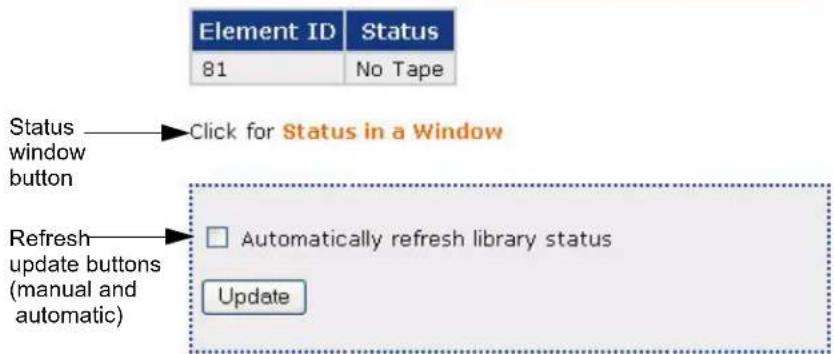
text_image
Element ID Status 81 No Tape Status window button Click for Status in a Window Refresh update buttons (manual and automatic) Automatically refresh library status UpdateFigure 4-2 Remote Management Utility–Library and Tape Drive Status
If desired, you can click the Status Window button to open a separate Status window. Figure 4-3 shows an example of a stand-alone Status window.
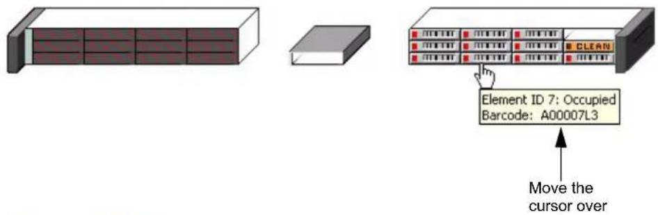
text_image
Element ID 7: Occupied Barcode: A00007L3 Move the cursor overLibrary Status
| Item | Status |
| Motion: | Idle |
| Robot Status | Alive |
| Intervention Required: | NO |
| Robot Control Mode: | Random |
| I/E Port | Locked |
| Right Magazine | Locked |
| Left Magazine | Locked |
| Library Temperature | Normal: 24/75° |
| Auto Clean | OFF |
| Clean | Slot: 2 |
| Cleans Remaining: | Unknown |
Tape Drive Status
| Element ID | Status |
| 81 | No Tape |
Figure 4-3 Remote Management Utility-Status window
Note: By moving the cursor over the individual elements, you can see the status of that element.
Library status information
The Library Status section includes the following information.
Motion This indicates if the robot is active (moving a cartridge) or idle.
Robot Status This indicates if the robot has an error.
See Appendix E, Error Messages for help troubleshooting errors.
Intervention Required This indicates if you need to intervene.
See Appendix E, Error Messages.
Robot Control Mode This indicates the control mode–Random or Sequential.
I/E Port This indicates if the I/E Port is locked or unlocked.
See “Enabling and Disabling the I/E Port” on page 49 for instructions on how to lock and unlock the I/E port.
Right Magazine This indicates if the right magazine is locked or unlocked.
See "Loading Cartridges into a Magazine" on page 124 for instructions on how to lock and unlock the magazines.
Left Magazine This indicates if the left magazine (if present) is locked or unlocked. You can operate the library with one or two magazines (the second magazine is optional). You can also limit the number of slots visible to the SCSI interface for compatibility with backup software.
See "Setting the Data Cartridge Slot Count" on page 47
Library Temperature This indicates if there is a problem with the library's temperature.
See "Over Temperature" on page 250 for the corrective action for an over temperature condition.
Auto Clean This indicates if Auto Clean is turned on or off.
See "Setting Up Automatic Tape Drive Cleaning" on page 63 to determine if you want this function enabled or disabled.
Clean This indicates if a “fixed” cleaning slot has been set. Use this function in conjunction with the Auto Clean option.
See "Setting Up Automatic Tape Drive Cleaning" on page 63 for instructions on how to set s fixed cleaning slot.
Cleans Remaining. This indicates the number of cleanings remaining on the cleaning cartridge. See "Check the Cleaning Cartridge Status" on page 133 for additional information.
Notes: The cleaning count information is stored in the cartridge, so it must be used once to "start" the count. Until it is used the first time, the utility displays an "unknown" status.
The utility only displays the count if it is known.
If there is no barcode label on the cleaning cartridge, a power cycle causes the cleaning count information to be lost. If there is a barcode label on the cleaning cartridge, the library stores the information and recognizes it after a power cycle.
Tape drive status information
The Tape Drive Status section includes the following information.
Tape Drive Status
| Element ID | Status |
| 81 | No Tape |
Element ID Indicates the element address of the tape drive. Element addresses (indexes) identify locations within the library that can accept a cartridge. The StorageLibrary T24 library has three tape drive configuration options.
| Tape drive style Location Element Address | |
| Single full height Default 81 | |
| Second half height Top 82 | |
| Single half height Bottom 81 |
Status Indicates whether the tape drive is active (tape motion is occurring) or inactive.
Note: Moving the cursor over the tape drive element in the stand-alone status window shows the tape drive's status.
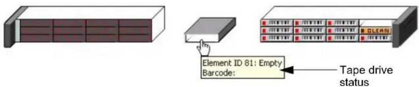
text_image
Element ID 81: Empty Barcode: Tape drive statusLibrary Status
| Item | Status |
| Motion: | Idle |
| Robot Status | Alive |
| Intervention Required: | NO |
| Robot Control Mode: | Random |
| I/E Port | Locked |
| Right Magazine | Locked |
| Left Magazine | Locked |
| Library Temperature | Normal: 24/75° |
| Auto Clean | OFF |
| Clean | Slot: 2 |
| Cleans Remaining: | Unknown |
INVENTORY
The Inventory section provides information from the library's cartridge inventory. The library maintains a cartridge inventory to keep track of where cartridges are located. An inventory is automatically performed each time the library is powered on, each time a cartridge is inserted or removed from the library, and each time a magazine is inserted into the library. In performing an inventory, the library checks for cartridges in the cells and scans each cartridge's bar code label.
Note: You can move the cursor over any inventory location to view that location's status.

natural_image
Illustration of three different server racks: a front-mounted rack, a gray rectangular unit, and a clean rack unit (no text or symbols visible)Inventory
| Element ID | Type: Number | Status (POVA) | Label valid | Label |
| 97 | Robot | Empty (1010) | 1 | |
| 113 | E/E Port | Empty (1011) | 1 | |
| Clean | Occupied (1111) | 1 | CLNA01L3 | |
| 1 | Slot: 3 | Occupied (1111) | 1 | A00001L3 |
| 2 | Slot: 4 | Occupied (1111) | 1 | A00002L3 |
| 3 | Slot: 5 | Occupied (1111) | 1 | A00003L3 |
| 4 | Slot: 6 | Occupied (1111) | 1 | A00004L3 |
| 5 | Slot: 7 | Occupied (1111) | 1 | A00005L3 |
| 6 | Slot: 8 | Occupied (1111) | 1 | A00006L3 |
| 7 | Slot: 9 | Occupied (1111) | 1 | A00007L3 |
| 8 | Slot: 10 | Occupied (1111) | 1 | A00008L3 |
| 9 | Slot: 11 | Occupied (1111) | 1 | A00009L3 |
| 10 | Slot: 12 | Occupied (1111) | 1 | A00010L3 |
| 81 | Drive: 1 | Empty (1011) | 1 |
POVA flags are defined as:
P - Slot Present
0 - Slot Occupied
V - Slot Occupied and Valid
A - Slot Accessible
Figure 4-4 Remote Management Utility–Inventory page
The Inventory section includes the following information:
SCSI Address This indicates the element address. Element addresses identify locations within the library that can accept a cartridge. The addresses are defined as follows:
Slots-Address 0 through 23 represent magazine slots.
The slot numbers begin with the right magazine and continue with the left magazine.
The storage cells decrease or increase based on the I/E Port setting (enabled or disabled). Disabling the I/E Port increases the storage cell count. See “Enabling and Disabling the I/E Port” on page 49.
▶ Tape Drives—The addresses for the tape drives are defined as follows:
| Tape drive style Location Element Address | |
| Single full height Default 81 | |
| Second half height Top 82 | |
| Single half height Bottom 81 |
Type: Number This indicates the type of the address (I/E port, slot, or tape drive).
Status This indicates the status (POVA) of the address, as follows:
| Letter or Number | Definition |
| “P” | Slot Present |
| “O” | Slot Occupied |
| “V” | Slot Occupied and Valid |
| “A” | Slot Accessible |
| 1 | Yes |
| 0 | No |
Label Valid Indicates whether the bar code label information for the element is considered valid (1) or questionable (0). The bar code label information is considered questionable if the library had a problem reading the label.
Label If the element contains a cartridge, this field provides the bar code label information for the cartridge. If the cartridge does not contain a bar code label, it shows the cell number (the same as the address). information for the cartridge. If the cartridge does not contain a bar code. This field also indicates the type of data cartridge (L1=LTO1, L2=LTO2, and L3=LTO3).
SETTING CONFIGURATION OPTIONS
Click on Configure at the top of the page to view the Configuration page.
Figure 4-5 shows an example of the Configuration page.
From the Configuration page, you can change settings in the following sections:
▶ Change library configurations and operation mode
Change Web access password and front panel password
Change the background color of the utility
▶ Change the tape drive cleaning options
▶ Change Ethernet configuration
Establish a "hint" in case you forget your password
To enact changes you make on the Configuration page, enter the password (if you previously set one) in the Web Access Password field, and click the Update button below the fields. A confirmation message appears. Click on the link provided or the product name to return to the Status page.
TANDBERG DATA Securing your Information
STORAGELIBRARY T24

text_image
Home Configure SCSI Panel Mode Skin Cleaning NET SNMP FTP e-mail WAP Hint Statistics Tools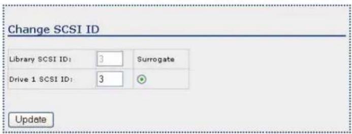
text_image
Change SCSI ID Library SCSI ID: 3 Surrogate Drive 1 SCSI ID: 3 UpdateFigure 4-5 Remote Management Utility-Configuration Home page
CHANGING LIBRARY CONFIGURATIONS
You can change the following settings:
SCSI ID (SCSI version) You can change the SCSI IDs for the tape drive(s) if they conflict with other devices on the SCSI bus. See page 52 for more information about SCSI IDs. The above screen shows a library with two tape drives installed.
Notes: The library communicates with the host through the SCSI interface of the tape drive(s) via the ADI serial interface. The SCSI interface as seen by the host is the SCSI interface of the tape drive. The library is shown as LUN 1 of the tape drive's SCSI ID.
For additional information, see:
The tape drive's Product Manual for tape drive information.
Automation/Drive Interface - Command (ADC) for ADI information.
SCSI Bridge If you have two tape drives installed in the library, you can assign one of them to act as the primary SCSI interface (bridge) for the library. If you have only one tape drive installed, it automatically acts as the SCSI bridge.
▶ SCSI configuration—to change the SCSI bridge assignment, click the radio button to the right of the tape drive and click Update.
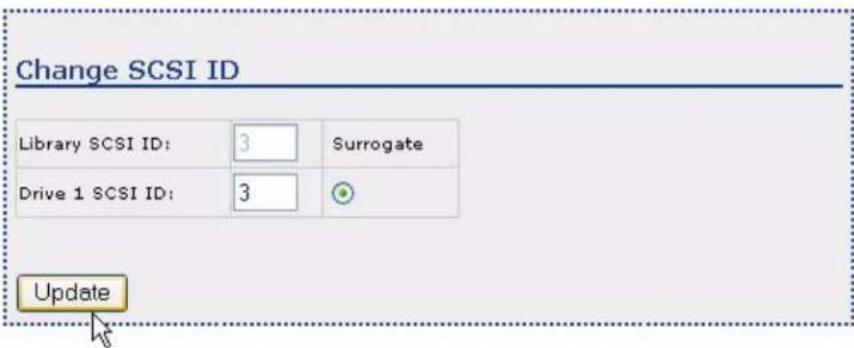
text_image
Change SCSI ID Library SCSI ID: 3 Surrogate Drive 1 SCSI ID: 3 UpdateFibre Channel configuration—to change the SCSI bridge assignment, click the radio button to the right of the tape drive and click Update.
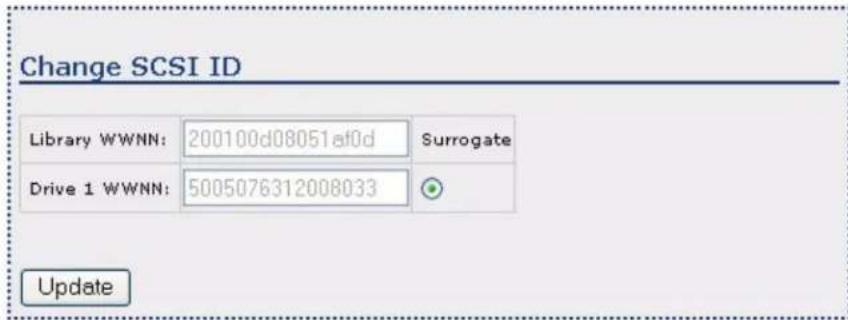
text_image
Change SCSI ID Library WWNN: 200100d08051af0d Surrogate Drive 1 WWNN: 5005076312008033 Update! Important
Once you click the Update button and you receive the confirmation message, you need to reset the library.
- See "Advanced" on page 114 for instructions on how to reset the library.
- See "Tape Drive SCSI Interface (Library Bridge)" on page 54 to set the SCSI bridge from the front panel.
Panel – If desired, you can use the Remote Management utility to change the password that protects access to the library's menus from the front panel.

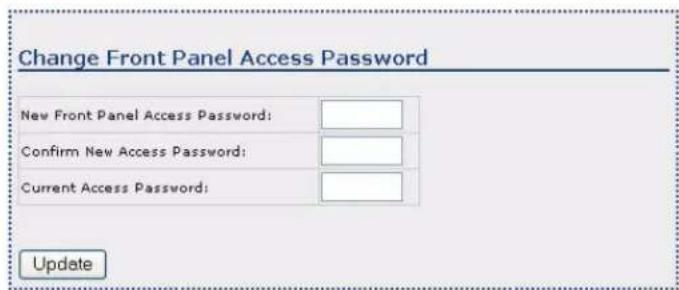
text_image
Change Front Panel Access Password New Front Panel Access Password: Confirm New Access Password: Current Access Password: UpdateTo set or change this password:
- Enter a new password in the "New Front Panel Access Password" field. See page 78 for more information about password protecting the front panel menus, including length restrictions.
- Re-enter the new password in the "Confirm New Access Password" field.
- If you are changing an existing password, enter the current password in the "Current Access Password" field.
To cancel an existing password, enter the current password in the "Current Access Password" field and leave the "New Front Panel Access Password" and "Confirm New Access Password" fields blank.
Note: The library's front panel access password is separate from the web access password (WAP). The front panel password limits actions from the front panel. The web access password prevents using the Remote Management utility (see page 103 for more information about the WAP).
Mode You can configure two library modes: Emulation and Control.

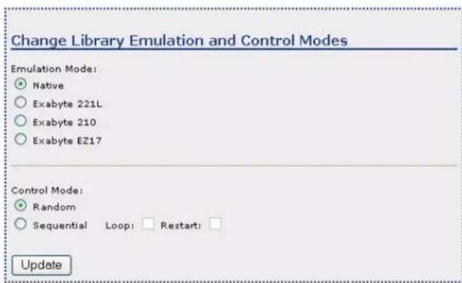
text_image
Change Library Emulation and Control Modes Emulation Mode: ● Native ○ Exabyte 221L ○ Exabyte 210 ○ Exabyte EZ17 Control Mode: ● Random ○ Sequential Loop: □ Restart: □ UpdateEmulation—If your backup software has not yet been certified for the StorageLibrary T24, you can set the library to emulate:
Exabyte 221L
Exabyte 210 library
Exabyte EZ17 autoloader
Because most backup applications are certified for these products, changing the emulation mode may allow these applications to support the library. See page 57 for more information about emulation modes.
▶ Control (operation mode)—You can operate your library in either Random mode or Sequential mode.
| Mode Use | |
| Random(the default) | Use this mode with an application that controls the library. |
| Sequential Only | use this mode if you plan to operate the library without a backup application. In Sequential mode, the library automatically processes cartridges in sequential order without direction from an application. See page 59 for information about setting the library to operate in Sequential mode from the front panel. |
| ! Important | If you are using a backup application which is capable of controlling the library, do not configure the library to operate in Sequential mode. |
You can also set the restart and loop options as follows:
▶ Restart option—Determines what the library does after it is reset, power cycled, or when a magazine has been re-inserted.
| Mode Use | |
| Enabled The library restarts at the beginning of the cartridge sequence. | |
| Disabled The library resume where it left off when the interruption occurred. | |
Loop option—Determines what the library does after it has finished processing the last cartridge in the sequence.
| Mode Use | |
| Enabled The library | loops back to the first cartridge in the sequence and begins processing the cartridges again. |
| Disabled The library | stops and waits for operator intervention. Operator intervention typically means removing cartridges for storage and inserting new cartridges. |
Skin This option allows you to change the background color of the utility.
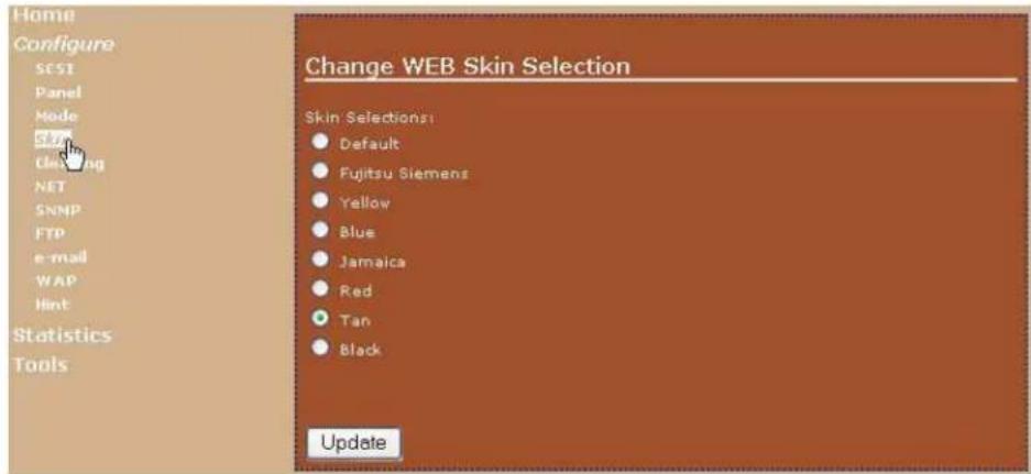
text_image
Home Configure SCST Panel Mode S### Clearing NET SNMP FTP e-mail WAP Hint Statistics Tools Change WEB Skin Selection Skin Selections: Default Fujitsu Siemens Yellow Blue Jamaica Red Tan Black UpdateCleaning The Autoclean option enables the library to automatically perform tape drive cleaning without operator intervention.

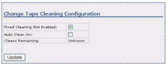
text_image
Change Tape Cleaning Configuration Fixed Cleaning Slot Enabled: ✓ Auto Clean On: □ Cleans Remaining: Unknown UpdateCleaning the tape drive(s):
Via the Remote Management Utility—To set automatic cleaning with the Remote Management Utility:
a. Enable the cleaning slot via the front panel (see page 63).
b. Load a cleaning cartridge into the library.
Slot/Cell 2—if the I/E Port is enabled
Slot/Cell 1—if the I/E Port is disabled
c. Toggle the Auto Clean On button (a check mark appears).
d. Click the Update button.
Via the front panel—See page 63 for information about using the front panel to set the Autoclean option.
See "Check the Cleaning Cartridge Status" on page 133 for information about the cleaning cartridge "count" (number of cleanings remaining).
CHANGING ETHERNET CONFIGURATIONS
You can change the following settings:
NET This option allows you to change the Ethernet addresses.
| Setting DescriptionTo change these setting via the front panel, see “Setting Ethernet Configuration Options” on page 67. | |
| Static IP If you | are using static addressing (DHCP off), specify the values for this address. If you are using dynamic addressing, specify 0 for this address. |
| Subnet Mask | If you are using static addressing (DHCP off), specify the values for this address. If you are using dynamic addressing, specify 0 for this address. |
| Gateway If you | are using static addressing (DHCP off), specify the values for this address. If you are using dynamic addressing, specify 0 for this address. |
| DHCP If you | are using dynamic addressing (DHCP on), this field indicates the IP address. The default setting for the library is DHCP enabled.Note: If the DHCP address changes during your session, you will need to check the new address on the library’s LCD (see page 141) and re-direct your browser to the new address. |
SNMP If you need to identify the library's SNMP settings to an application, you can view the settings and change them, if desired.
Both the SNMP System Name and SNMP System Location are displayed on the Home page.

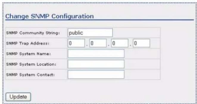
text_image
Change SNMP Configuration SNMP Community String: public SNMP Trap Address: 0 , 0 , 0 , 0 SNMP System Name: SNMP System Location: SNMP System Contact: UpdateFTP If you plan to use the library's FTP interface to upgrade firmware or obtain diagnostic listings, you can view the default FTP User Name and change it, if desired.
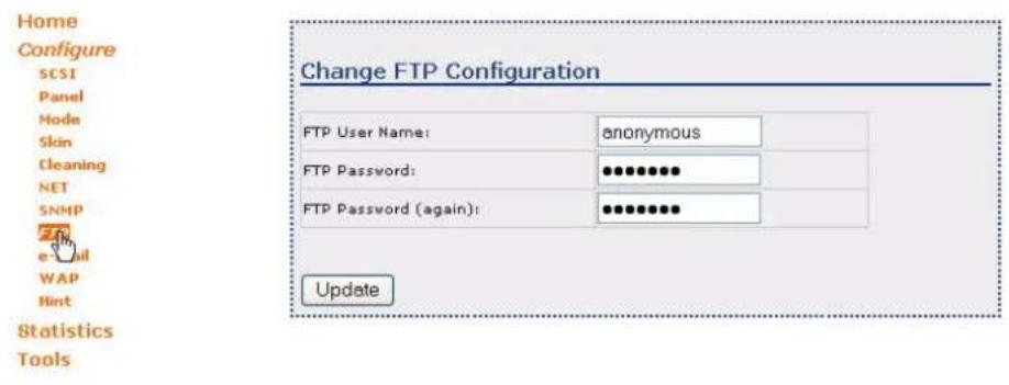
text_image
Home Configure SCSI Panel Mode Skin Cleaning NET SNMP e-mail WAP Hint Statistics Tools Change FTP Configuration FTP User Name: anonymous FTP Password: •••••••• FTP Password (again): ••••••••• UpdateThe default values are:
▶ User name: anonymous
▶ Password: Exabyte
Note: The user name and password are case-sensitive.
For information about accessing the library's FTP interface and using an FTP utility to upgrade firmware or obtain diagnostic listings, see page 190.
E-mail If desired, you can receive e-mail alerts from the library in the event of error conditions or exceptions. If you want to receive these e-mail alerts, enter the IP address of your e-mail server, your e-mail user name, and your e-mail address. You can also enter a sender e-mail address that will appear in the "From" field of messages that are sent from the library. This address can be anything you like, but be aware that some e-mail servers have limitations on the type of address you can specify.
WAP Web Access Password-If you have set up a password for changing options on the Configuration page, enter the password here before you click on the Update button to enact the changes.
Note: If you forget your web access password, click on Get Web PW Hint, described below.
SETTING WEB ACCESS PASSWORD PROTECTION
Set Web Access Password If desired, you can set up a password to prevent unauthorized users from using the Remote Management utility to change the library's configuration settings from the Configuration page.

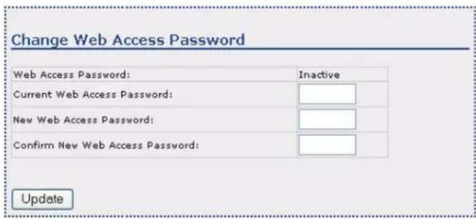
text_image
Change Web Access Password Web Access Password: Inactive Current Web Access Password: New Web Access Password: Confirm New Web Access Password: UpdateTo set up a password, follow these steps:
- If a password has already been set and you want to change it, enter the current password in the "Current Web Access Password" field.
- Enter a new password for the page in the "New Web Access Password" field. The password can be from 1 to 11 letters and can include spaces. The password is not case-sensitive.
- Re-enter the new password in the "Confirm New Web Access Password" field.
After filling in the fields, click on the Update button to enact the password.
To cancel the password, enter the current password in the Current Web Access Password, and leave the New Web Access Password and Confirm New Web Access Password fields blank. Then, click the Update button.
Get Web Password Hint By clicking the Get Web Password Hint button, you will receive an encrypted version of a password. Contact Technical Support at www.tandbergdata.com to have your password decrypted.
text_image
Get Web Access Password Hint This Hint, can be provided to Tech Support whenever the Password is forgotten. Get Web PW HintVIEWING INFORMATION ON THE STATISTICS PAGE
Click on Statistics to view the Statistics page. Figure 4-6 shows the Statistics Home page.


Home
Configure
Statistics
Library
Network
Drive
Tools
Library Statistics
| Parameter | Count |
| Move Count | 22529 |
| Pick Retry Count | 1 |
| Put Retry Count | 3 |
| Scan Count | 1560 |
| Scan Retry Count | 63 |
| Scan Fail Count | 40 |
| Element ID | Type: Number | Total Puts | Put Retries | Pick Retries |
| Clean | 709 | 0 | 0 | |
| 1 | Slot: 3 | 608 | 0 | 0 |
| 2 | Slot: 4 | 502 | 0 | 0 |
| 3 | Slot: 5 | 511 | 0 | 0 |
| 4 | Slot: 6 | 459 | 0 | 0 |
| 5 | Slot: 7 | 521 | 0 | 0 |
| 6 | Slot: 8 | 484 | 0 | 0 |
| 7 | Slot: 9 | 447 | 0 | 0 |
| 8 | Slot: 10 | 434 | 0 | 0 |
| 9 | Slot: 11 | 434 | 0 | 0 |
| 10 | Slot: 12 | 433 | 0 | 0 |
| 113 | E/E Port | 39 | 0 | 0 |
Figure 4-6 Remote Management Utility–Statistics Home page
LIBRARY STATISTICS
The Statistics/Library (Home) page provides the following information:
Move Count This indicates the total number of moves that have taken place in the library. A move is when the robot removes a cartridge:
from a slot (or the I/E port) to a tape drive
from a tape drive to a slot (or the I/E port)
Pick Retry Count This indicates the total number of the robot has retried removing a cartridge from a cell or from the tape drive.
Put Retry Count This indicates the total number of the robot has retried placing a cartridge in a cell or in the tape drive.
Scan Count This indicates the total number of the bar code scanner has scanned a bar code label.
Scan Retry Count This indicates the total number of the bar code scanner has retried scanning a bar code label.
Scan Fail Count This indicates the total number of the bar code scanner failed scanning a bar code label. The scanner tries to scan a bar code several before it logs a failure.
ELEMENT STATISTICS
The Element Statistics section of this page provides the following information:
Element ID These are the populated slots in the library. This screen shows the library with two left magazine "blanks" installed.
Type: Number This field shows either the type of slot: cleaning cartridge or I/E port, or the number of the cell.
Total Puts This indicates the total number of times the robot put a cartridge into this cell.
Put Retries This indicates the total number of times the robot has retried putting a cartridge into this cell.
Pick Retries This indicates the total number of times the robot has retried picking a cartridge from this cell.
NETWORK STATISTICS
The Statistics Network page provides the following information:

Network Statistics
| Parameter | Count |
| WWW Hit Count | 91 |
| FTP Count | 0 |
| E-mails Sent | 0 |
| Trapped Events | 0 |
WWW Hit Count This indicates the total number of the library has been accessed from the Internet (via the Remote Management Utility).
FTP Count This indicates the total number of FTP sessions that have occurred.
E-mails Sent This indicates the number of e-mail notifications sent on behalf of the library.
Trapped Events This indicates the number of SNMP trapped events that have been detected and signed.
TAPE DRIVE STATISTICS
The Statistics Tape Drive page provides the following information (shown with two half-height tape drives installed):

Drive Statistics
| Drive | Parameter | Count |
| 1 | Drive Load Count | 5637 |
| 1 | Drive Reload Count | 1 |
Drive Load Count This indicates the number of the library has loaded a cartridge into the tape drive.
Drive Reload Count This indicates the number of the library has reloaded a cartridge into the tape drive.
Drive 1 indicates either the lower half height tape drive or the full height tape drive.
▶ Drive 2 indicates the upper half height tape drive (if installed).
USING THE UTILITY'S TOOLS
Click on Tools at the top of the page to view the Tools Home page.

STORAGELIBRARY T24
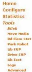
text_image
Home Configure Statistics Tools Blink Move Media Rd Elem Stat Park Robot Lib CUP Drive CUP Lib Test Logs AdvancedBlink the LCD Display
Blink the Library LCD display in order to help locate this specific Library device. Pressing any Library panel button will terminate the blinking.
Blink for 30 seconds
○ Blink for 60 seconds
○ Blink until stopped
○ Stop blinking
Blink
Figure 4-7 Remote Management Utility-Tools Home page
Blink This option helps you to identify the library if it is in a rack with multiple devices. Use this option to locate the library to load cartridges, perform manual operations, and so forth.
Move Media This option allows you to move media between slots (including the I/E port) and the tape drive(s).
Rd Elem Stat Read Element Status Command – This option performs an Element Status Scan.
Park Robot This option parks the robot. You need to park the robot before moving or shipping the library.
After you successfully park the robot (front panel confirmation message: Park for Shipping Good), replace the shipping lock prior to moving the library (see "Replacing the Shipping Lock" on page 235).

text_image
Home Configure Statistics Tools Blink Move Media Rd Elem Stat Park Robot Lib CUP Drive CUP Lib Test Logs AdvancedPark the Robot
Press the Park button to place the robot in it's shipping position. Remember to install the Shipping Lock when transporting the unit.
Park
Lib CUP Library Code Update – Use this option to update the code in the library. The following figure shows the options for updating the library's code.
! Important
Make sure that you select and download the correct firmware files. Firmware for other Tandberg Data products is not compatible with the StorageLibrary T24.

Caution
Do not attempt to perform library operations or power down the library until after it automatically resets.
Choose the option, press Select, and then follow the instructions as shown below.

Library Code Update
Select the method below that you would like to use to update the Library firmware.
○ Update automatically from the WEB
○ Update from the WEB but let me choose
Update from a file of my choice
○ Update from the USB port
Select
When you press the Select button, the following screen appears. Once you determine that it is acceptable to continue, press the OK button.
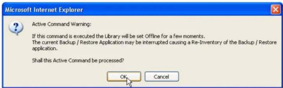
text_image
Microsoft Internet Explorer Active Command Warning: If this command is executed the Library will be set Offline for a few moments. The current Backup / Restore Application may be interrupted causing a Re-Inventory of the Backup / Restore application. Shall this Active Command be processed? OK CancelUpdate automatically from the WEB
Automated WEB based Code Update
Press the Find Latest Update button to start the Automated WEB based Code Update process.
After you press the button, the system will automatically establish the required connection to the server that holds the Firmware for this device. It will then determine if a newer version of the Firmware is available and prompt you to decide if you want it installed. The Code Update will start only after you have agreed to upgrade the Firmware.
The FTP location that this process will use is automatically entered for you. Only change the FTP Location if Technical Support has given you a specific IP address to use.

text_image
Ftp Location: 161.81.7.101 Find Latest UpdateUpdate from the WEB but let me choose
WEB based Code Update
Press the Get File Selection button to start the WEB based Code Update process.
After you press the button, the system will automatically establish the required connection to the server that holds the Firmware for this device. You will then be given a selection of files to choose from. Only after you have chosen the desired file will the Code Update start.
The FTP location that this process will use is automatically entered for you. Only change the FTP Location if Technical Support has given you a specific IP address to use.
Ftp Location: 161.81.7.101
Get File Selection
Update from a file of my choice
WEB based Library Code Update
Enter the file name below or use the Browse button to locate the desired file. Then press the Update button.
After you press the Update button, this page will remain displayed until all of the data has been transferred to the Library.
Do not turn off power to the Library after you have pressed the Update button
Update using this file:
Browse...
Update
Update from the USB port
USB File System Navigation
Navigate the USB File System until the desired TFW file is located. Click on that file to select it. You will be prompted before any firmware is transferred.
| Name | Size | Date |
| V1C202.TFW | 4194560 | 2007-02-22 14:00:42 |
Drive CUP Tape Drive Code Update – Use this option to update the code in the tape drive(s). The following figure shows the options for updating the code.
! Important
Make sure that you select and download the correct firmware files. Firmware for other Tandberg Data products is not compatible with the tape drives.

Caution
Do not attempt to perform library operations or power down the library until after it automatically resets.
Choose the options, press Select, and then follow the instructions as shown below.
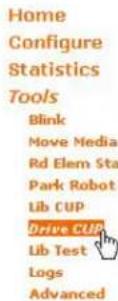
Drive Code Update
Select the Drive that you want to update.
IBM ULTRIUM-TD3 S/N: 1200019510 REV: 6BAO
Select the method below that you would like to use to update the Drive firmware.
○ Update from the WEB but let me choose
Update from a file of my choice
Update from the USB port
Select
When you press the Select button, the following screen appears. Once you determine that it is acceptable to continue, press the OK button.
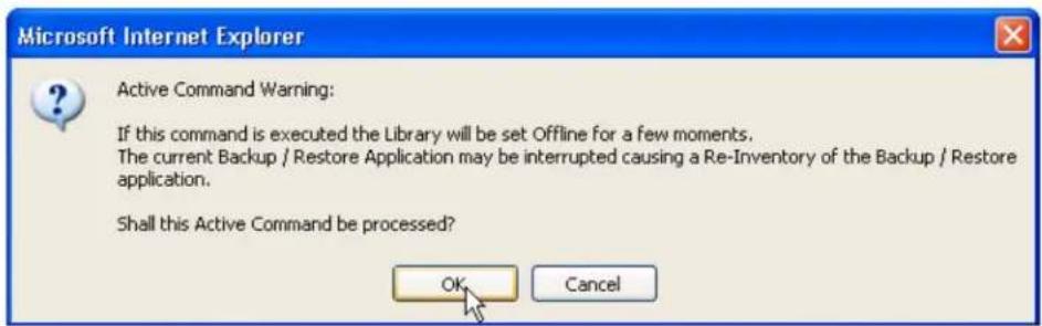
text_image
Microsoft Internet Explorer Active Command Warning: If this command is executed the Library will be set Offline for a few moments. The current Backup / Restore Application may be interrupted causing a Re-Inventory of the Backup / Restore application. Shall this Active Command be processed? OK CancelUpdate from the WEB but let me choose
WEB based Drive Code Update
Press the Get File Selection button to start the WEB based Drive Code Update process.
After you press the button, the system will automatically establish the required connection to the server that holds the Firmware for this device. You will then be given a selection of files to choose from. Only after you have chosen the desired file will the Code Update start.
The FTP location that this process will use is automatically entered for you. Only change the FTP Location if Technical Support has given you a specific IP address to use.
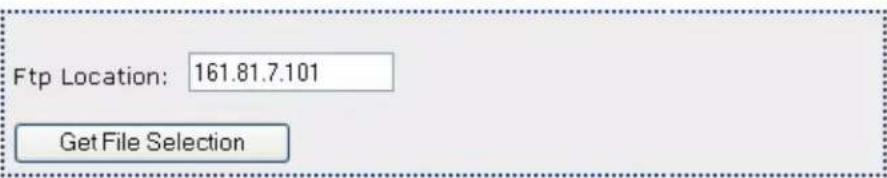
text_image
Ftp Location: 161.81.7.101 Get File SelectionUpdate from a file of my choice
WEB based Drive Code Update
Enter the file name below or use the Browse button to locate the desired file. Then press the Update button.
After you press the Update button, this page will remain displayed until all of the data has been transferred from the File.
Once all the data has been transferred from the File, it will then be transferred to the Drive. That phase can take over 15 minutes to complete. A progress page will be displayed during that phase.
Do not turn off power to the Library after you have pressed the Update button

text_image
Update using this file: Browse... UpdateUpdate from the USB port
USB File System Navigation for Drive Code Update
Navigate the USB File System until the desired .FMR or .E file is located. Click on that file to select it. You will be prompted before any firmware is transferred.
Lib Test Library Test – Use this option to run test's on the library. None of these tests will write data to tape, but some of them will load cartridges into and out of the tape drive(s). The following tests are available:
| Test Description | |
| Basic Load/Unload Loads cartridges into and out of the tape drive(s) | |
| Random Slot to Slot Move | Moves cartridges from slot to slot in random order (the library must have empty slots to conduct this test) |
| Simple Positioning Moves the robot sequentially around the library starting at slot 1 | |
| Harder Positioning Moves the robot randomly around the library and positions it at various locations | |
To stop a test in progress, click the Stop the Test button. If you press this button, the library completes the current action, and then stops. For example, if the library loaded a cartridge into a tape drive, it unloads it and returns it to its slot before stopping the test.
Diagnostic Test Results
Stop the Test
Diagnostic test in progress. Please wait.
Logs Occasionally, you may be asked by Technical Support to provide diagnostic logs (sometimes called dumps). Use this option to create these logs. You can select the device that you want logs for and how to handle them.

text_image
Home Configure Statistics Tools Blink Move Media Rd Elem Stat Park Robot Lib CUP Drive CUP Lib Test Loss AdvancedLog Tools
Look at the NVRAM log
○ Look at the Cartridge Memory Information log
○ Send the internal log to a local file
○ Send the internal log to a USB device
Log
Advanced Use the advanced tools with caution as some of the features may alter the configuration in such a way that you may lose Network connectivity.
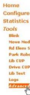
Advanced Features
Select the procedure you would like from the selections below then press the Submit button. Note that some of the procedures may alter the configuration of this library in such a way that you may loose network connectivity with this library. Use these procedures carefully.
Reset the Library
○Restore to Default Configuration
Submit
Update Library Ring - Click to update or enable the Library Ring system of WEB links.
Reset the library—Resets the library remotely.
Restore to Default Configuration—Restores the system defaults.
Update Library Ring This option allows you to link multiple libraries in your system.
Update the Library Ring
Enter the IP address of the library that you want to link to with the Next and Prev links. Enter all ZERO's for the IP address to disable that link.
| Next Library | 0 | . | 0 | . | 0 | . | 0 |
| Prev Library | 0 | . | 0 | . | 0 | . | 0 |
Update
NOTES
5
After you have configured your library, you can add cartridges and put it into operation. You can operate the library in either Random or Sequential mode.
- Random mode (the default)—The library processes cartridges according to commands issued from an application.
Sequential mode—The library automatically processes the cartridges in sequential order. See page 59 for instructions on how to set the library to operate in Sequential mode.
! Important
If you are using a backup application which is capable of controlling the library, do not configure the library to operate in Sequential mode.
During normal operation, you do not need to intervene in library activities. However, you may occasionally need to perform the following tasks, described in this chapter.
| To view this information... go to... | |
| Preparing cartridges page 119 | |
| Inserting and moving cartridges page 120 | |
| Loading cartridges into a magazine page 124 | |
| Removing cartridges from the library page 126 | |
| Issuing a Re-inventory command to the library page 128 | |
| Loading and unloading cartridges from the tape drive(s) page 129 | |
| Cleaning the tape drive(s) page 132 | |
| Resetting the library | page 138 |
| Storing cartridges that you have removed from the library | page 140 |
You can monitor library operations by viewing the operator panel or by using the library's Remote Management Utility (see Chapter 4). The Home screen (shown here) provides continuous updates on the activities of the library and tape drive(s).
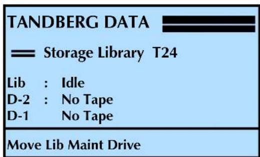
text_image
TANDBERG DATA —— Storage Library T24 Lib : Idle D-2 : No Tape D-1 No Tape Move Lib Maint DriveThe status LEDs, located to the left of the operator panel buttons (see Figure 5-1), also indicate library activity as follows:
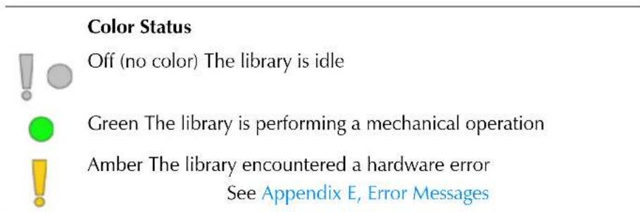
text_image
Color Status Off (no color) The library is idle Green The library is performing a mechanical operation Amber The library encountered a hardware error See Appendix E, Error Messages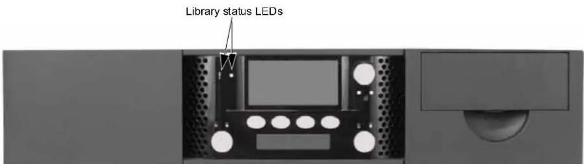
text_image
Library status LEDsFigure 5-1 Location of status LED
PREPARING CARTRIDGES
Be sure to use the appropriate cartridges for the tape drive(s). Table 5-1 shows the cartridge and write/read compatibility for the LTO Ultrium tape drive in the library.
Table 5-1 Tape drive cartridge read/write compatibility
| LTO Ultrium Tape Drive | Ultrium 3 (slate blue) | Ultrium 2 (purple) | Ultrium 1 (black) | LTO Ultrium cleaning cartridge | |||
| Read | Write | Read | Write | Read | Write | ||
| LTO-3 | √ | √ | √ | √ | √ | No | √ |
| LTO-2 | No | No | √ | √ | √ | √ | √ |
Tip Cartridges with bar code labels require much less time to scan than cartridges without bar code labels. We recommend applying bar code labels to each cartridge, including the cleaning cartridge.
Before inserting cartridges into the library, prepare them as follows:
- Affix the supplied bar code labels to the cartridges. Position each label in the indented area on the cartridge, as shown in Figure 5-2.
To prepare your own labels, refer to the Tandberg Data Bar Code Label Specification for LTO Ultrium Cartridges available at www.tandbergdata.com.
Note: The bar code labels provided with the library include labels for both data cartridges and cleaning cartridges.
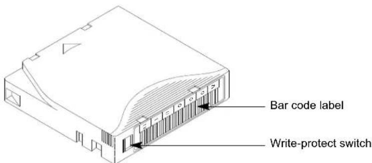
text_image
Bar code label Write-protect switchFigure 5-2 Bar code label placement and write-protect switch location
- Make sure the write-protect switch on each cartridge is set for the desired operation.
| If the switch... | the tape is... |
| does not cover the opening | write-enabled |
| covers the opening | write-protected |
INSERTING AND MOVING CARTRIDGES
LOADING CARTRIDGES INTO THE I/E PORT
In order to use the I/E Port to import and export cartridges, it must first be "enabled." See "Enabling and Disabling the I/E Port" on page 49.
To load cartridges through the I/E port:
-
Affix the bar code labels as described in "Preparing Cartridges" on page 119.
-
Press the I/E Port lock button. The unlock icon flashes () while the library initiates the unlock.
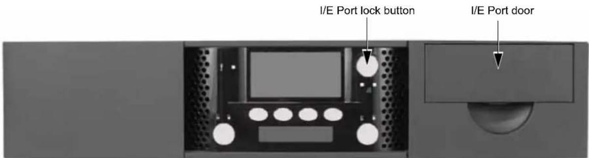
text_image
I/E Port lock button I/E Port doorFigure 5-3 Location of I/E Port lock button
-
Once the library unlocks the door (the unlock icon remains illuminated), open it by pulling the door latch toward you. Slide the drawer out to the end of travel. Swing the handle down and out of the way.
-
Load the cartridge into the slot with the bar code label facing to the left and the arrow facing to the right.
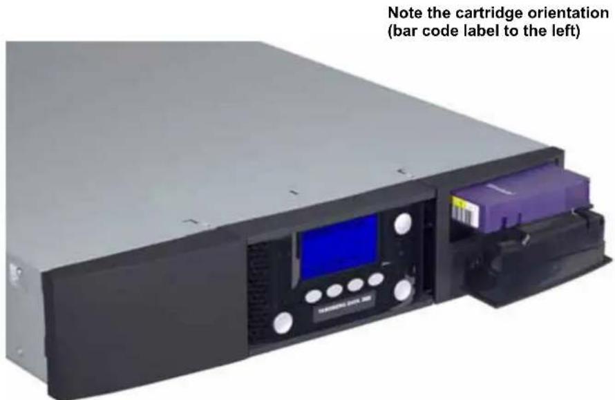
text_image
Note the cartridge orientation (bar code label to the left)Figure 5-4 Inserting a cartridge into the I/E port
- Push the cartridge into the slot until it stops.
- Close the I/E port door. The lock icon illuminates solid green ().
- Continue with the next section.
! Important If you plan to store a cleaning cartridge in the library, see "Setting Up Automatic Tape Drive Cleaning" on page 63.
IMPORTING CARTRIDGES THROUGH THE I/E PORT
After you have loaded a cartridge into the I/E Port, you need to "import" it into the library. The I/E port must be "enabled" (see "Enabling and Disabling the I/E Port" on page 49).
Note: The following steps describe how to import a cartridge through the I/E Port. Reverse the steps to "Export" a cartridge through the I/E Port.
To import cartridges through the I/E Port:
- At the Home screen, press Move.
If necessary, enter the operator panel password (see page 80).
- Press ▼ until the selection arrow (▶) points to Import, and then press Select.
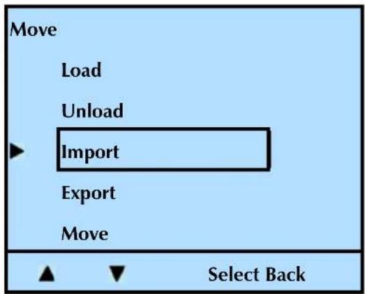
text_image
Move Load Unload Import Export Move Select Back- When the following screen appears, press Select.
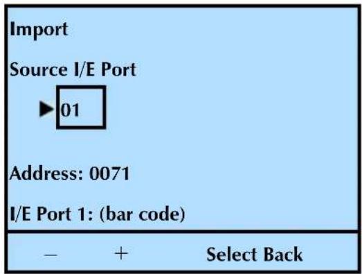
text_image
Import Source I/E Port ►01 Address: 0071 I/E Port 1: (bar code) - + Select Back- Press or to move through the slot choices. When the screen shows your "destination" (moving to) choice, press Select.
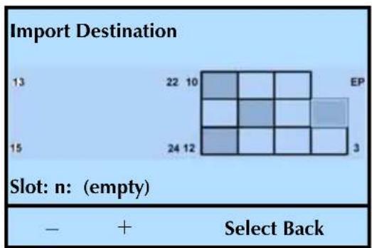
heatmap
Import Destination | Slot | 13 | 22 | 10 | EP | 15 | 24 | 12 | 3 | |---|---|---|---|---|---|---|---|---| | 13 | - | + | - | - | - | - | - | - | | 22 | - | + | + | - | - | - | - | - | | 10 | - | + | + | - | - | - | - | - | | 15 | - | + | + | + | - | - | - | - | | 24 | - | + | + | + | - | - | - | - | | 12 | - | + | + | + | - | - | - | - | | 3 | - | + | + | + | - | - | - | - | Slot: n: (empty) - + Select Back- Press OK to continue, or Back to cancel.
During the import, the front panel displays an Import Active message.
After a successful Import, the library displays this confirmation message: Import Good. Once the message appears, press OK to continue.
- Press Back (as needed) to return to the Home screen.
MOVING CARTRIDGES
The front panel Move command allows you to move cartridges between any of the elements inside the library (slots, a tape drive, or the I/E Port).
Note: The following steps describe how to move cartridges between slots. Use the same procedure to move cartridges to and from a tape drive or to and from the I/E Port.
When you move a cartridge to a tape drive, the cartridge automatically "loads" (the tape drive engages the take up reel).
- At the Home screen, press Move.
If necessary, enter the operator panel password (see page 80).
- Press ▼ until the selection arrow (▶) points to Move.
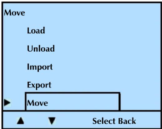
text_image
Move Load Unload Import Export Move Select Back- Press Select. Press ▼ until the selection arrow (▶) points to Slot.
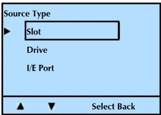
text_image
Source Type ► Slot Drive I/E Port ▲ ▼ Select Back- Press Select, and then press + or - to move through the slot choices. When the screen shows your "source" (moving from) choice, press Select.
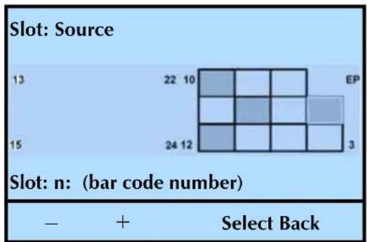
bar
| Slot | Bar Code Number | | :--- | :--- | | 13 | 22 10 | | 15 | 24 12 | | 22 | EP | | 3 | Select Back |Repeat steps 4 and 5 above to select your "destination" (moving to) choice.
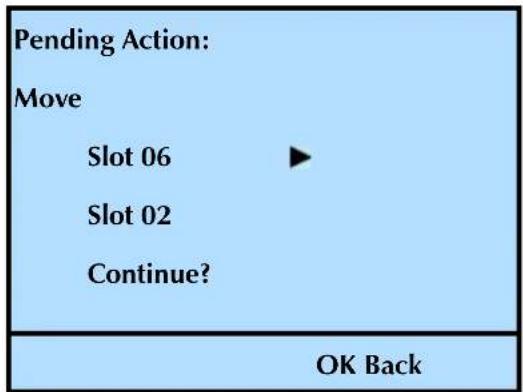
text_image
Pending Action: Move Slot 06 ▶ Slot 02 Continue? OK Back- Press OK to continue, or Back to cancel.
During the move, the front panel displays a Move Active message.
After a successful Move, the library displays this confirmation message: Move Good. Once the message appears, press OK to continue.
- Press Back (as needed) to return to the Home screen.
LOADING CARTRIDGES INTO A MAGAZINE
If you want to populate the entire magazine rather than loading cartridges one at a time, follow these steps.
! Tip
Cartridges with bar code labels require less time to scan than cartridges without bar code labels. We recommend applying bar code labels to each cartridge, including the cleaning cartridge.
To load cartridges into a magazine:
- Affix the bar code labels as described in "Preparing Cartridges" on page 119.
2. Press the magazine lock button shown in Figure 5-5.
If there is a command in progress, the library completes the command and positions the robot before unlocking and releasing the magazine.
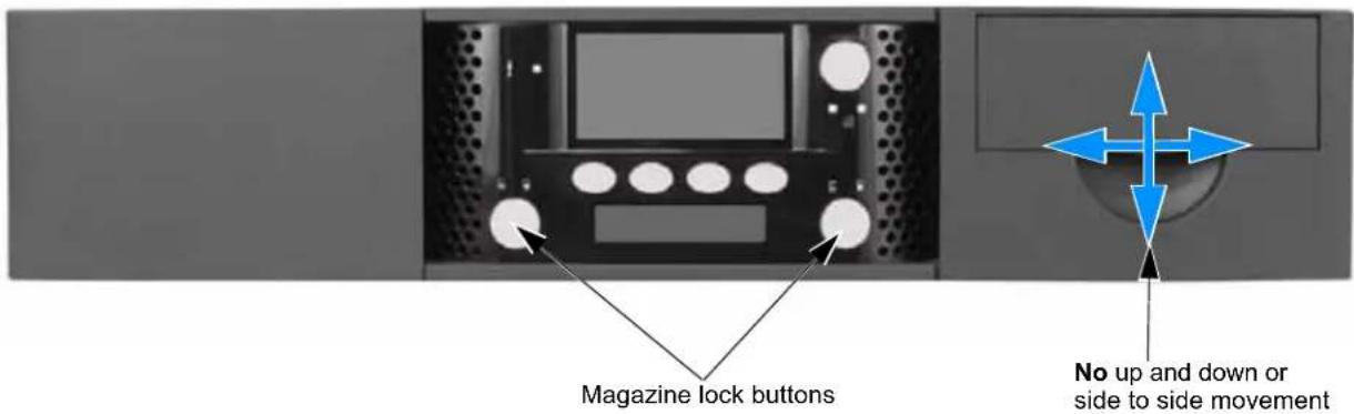
text_image
Magazine lock buttons No up and down or side to side movementFigure 5-5 Magazine lock buttons
- While supporting it, gently slide the magazine directly out of the library.

Caution
Use care not to twist the magazine or move it side to side as you insert or remove it from the library. Not inserting it straight into / pulling it straight out of the opening can damage components inside the library.
- Load the cartridges as shown here.
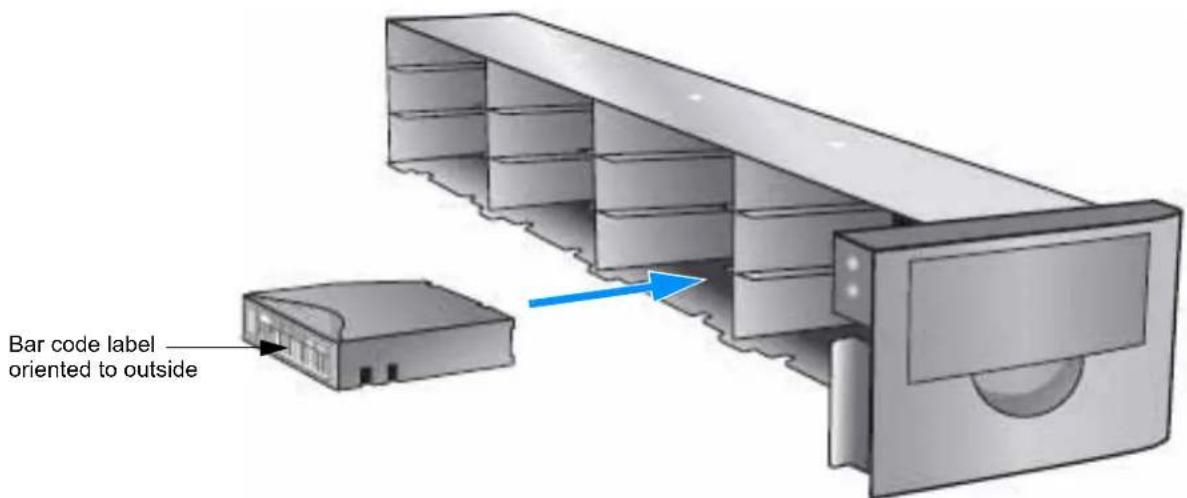
text_image
Bar code label oriented to outsideFigure 5-6 Loading cartridges into a magazine
Note: Use caution handling a magazine that is loaded with cartridges. Each cartridge weighs over 12 lb. (0.24 kg) each. Fully loaded, each magazine will weigh approximately 8.8 lbs. (4.0 kg).
- Securely grasp the magazine and slide it straight into the library (use care not to twist the magazine or move it side to side—it must be inserted “straight” into the opening). When you encounter resistance, press the magazine firmly, and you will hear it “snap” into place.
When the magazine is fully seated, the lock icon is solid green (), indicating that it is locked.
REMOVING CARTRIDGES FROM THE LIBRARY
This section describes removing cartridges one at a time through the I/E Port.
To remove multiple cartridges—see "Loading Cartridges into a Magazine" on page 124.
To remove cartridges after a power failure—see “Removing Cartridges Without Power” on page 181 (for both the library and a tape drive).
To remove cartridges:
- At the Home screen, press Move.
If necessary, enter the operator panel password (see page 80).
- Press ▼ until the selection arrow (▶) points to Export.
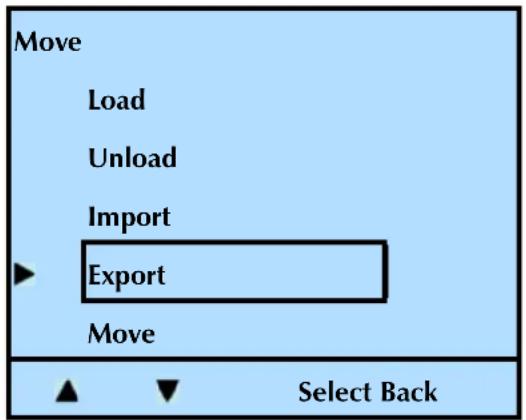
text_image
Move Load Unload Import Export Move Select Back- Press Select, and then press + or - to move through the choices. When the screen shows your "source" (moving from) choice, press Select.
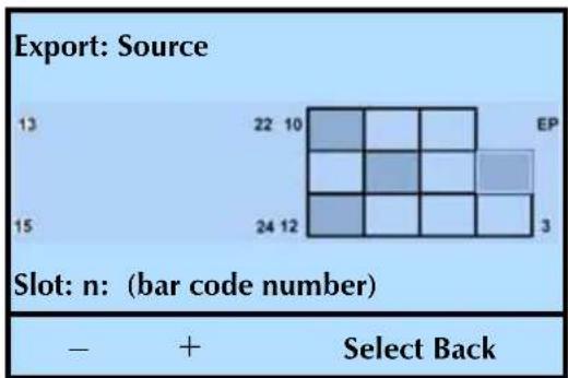
heatmap
Export: Source | | 13 | 22 | 10 | EP | |---|---|---|---|---| | 15 | | | | 3 | Slot: n: (bar code number) - + Select Back- When the following screen appears, press Select.
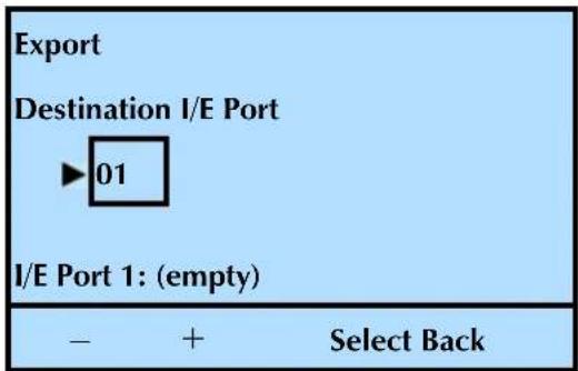
text_image
Export Destination I/E Port ►01 I/E Port 1: (empty) - + Select Back- Press OK to continue, or Back to cancel the action.
During the export, the front panel displays an Export Active message.
After a successful export, the library displays this confirmation message: Export Good. Once the message appears, press OK to continue.
- Remove the cartridge:
Press the I/E Port lock button. The unlock icon flashes ( ) while the library initiates the unlock.
Once the library unlocks the door (the unlock icon remains illuminated), open it by pulling the door latch toward you. Slide the drawer out to the end of travel. Swing the handle down and out of the way to access the cartridge.
Remove the cartridge and close the door (the lock icon illuminates green).
- Press Back (as needed) to return to the Home screen.
ISSUING A RE-INVENTORY COMMAND TO THE LIBRARY
Under normal circumstances, you should never have to issue a Re-inventory command to the library. The library automatically updates the inventory each time you power the unit on, reset the library from the front panel, and open and close an I/E Port or a magazine. If desired, you can issue this command to verify that the inventory shown on the display is correct.
Tip Cartridges with bar code labels require much less time to scan than cartridges without bar code labels. We recommend applying bar code labels to each cartridge, including the cleaning cartridge.
To re-inventory the library:
- At the Home screen, press Lib.
If necessary, enter the operator panel password (see page 80).
- Press ▼ until the selection arrow (▶) points to Inventory.
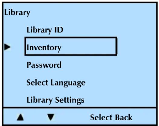
text_image
Library Library ID Inventory Password Select Language Library Settings ▲ ▼ Select Back-
Press Select.
-
Press ▼ until the selection arrow (▶) points to Re-Inventory.
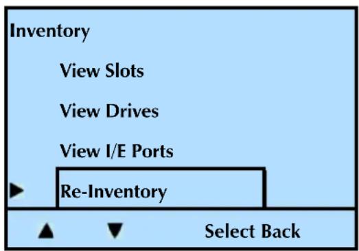
text_image
Inventory View Slots View Drives View I/E Ports ► Re-Inventory ▲ ▼ Select Back-
Press Select.
-
Press OK to continue or Back to cancel the action.
During the inventory, the front panel displays a Re-Inventory Active message, a status (XX%), and the current action: positioning, scanning, and so forth.
| Re-Inventory Active... |
| Lib: Update Inventory |
| XX% (Action taking place) |
| D-1: No Tape |
After a successful inventory, the library displays this confirmation message: Re-Inventory Good. Once the message appears, press OK to continue.
- Press Back (as needed) to return to the Home screen.
LOADING AND UNLOADING CARTRIDGES IN THE TAPE DRIVE
During normal operation, you do not need to instruct the library to load and unload cartridges in the tape drive(s). Your backup software controls these functions. However, you can use the operator panel to load and unload cartridges, if necessary. You may want to use these functions for testing purposes or for cleaning the tape drive(s). See page 135 for cleaning instructions.
LOADING A CARTRIDGE INTO A TAPE DRIVE
To load cartridges into a tape drive:
- At the Home screen, press Move.
If necessary, enter the operator panel password (see page 80).
- Press ▼ until the selection arrow (▶) points to Load.

text_image
Move Load Unload Import Export Move Select Back- Press Select, and then press + or - to move through the slot choices. When the screen shows your "source" (moving from) choice, press Select.
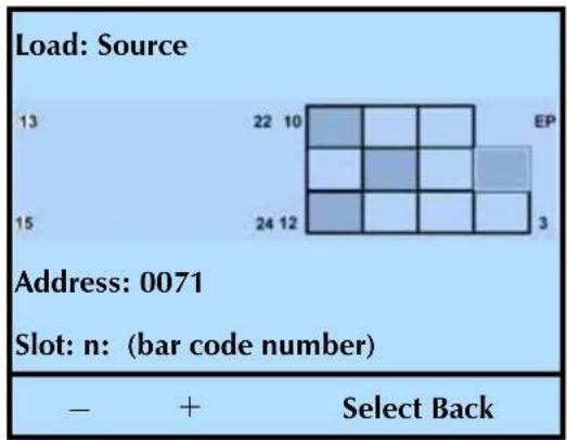
heatmap
Load: Source | | | | | | |---|---|---|---|---| | 13 | 22 10 | | | EP | | 15 | 24 12 | | | 3 | Address: 0071 Slot: n: (bar code number) - + Select Back- Press or to move through the tape drive choices (if more than one tape drive is installed). When the screen shows your "destination" choice, press Select.
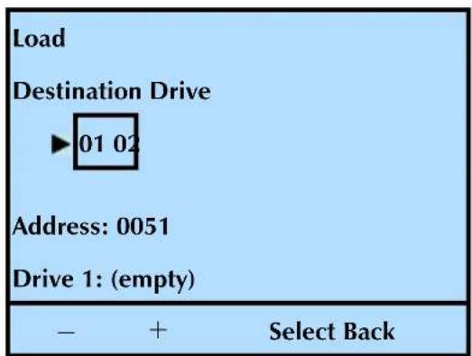
text_image
Load Destination Drive ►01 02 Address: 0051 Drive 1: (empty) - + Select Back- Press OK to continue, or Back to cancel.
During the load, the front panel displays a Load Active message.
After a successful Load, the library displays this confirmation message: Load Good. Once the message appears, press OK to continue.
- Press Back (as needed) to return to the Home screen.
UNLOADING A CARTRIDGE FROM A TAPE DRIVE
To unload a cartridge from a tape drive:
- At the Home screen, press Move.
If necessary, enter the operator panel password (see page 80).
- Press ▼ until the selection arrow (▶) points to Unload.
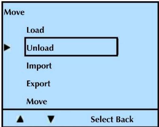
text_image
Move Load Unload Import Export Move Select Back- Press Select, and then press + or - to move through the tape drive choices (if more than one tape drive is installed). When the screen shows your "source" (moving from) choice, press Select.
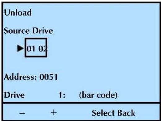
text_image
Unload Source Drive ►01 02 Address: 0051 Drive 1: (bar code) - + Select Back- Press or to move through the slot choices. When the screen shows your "destination" (moving to) choice, press Select.
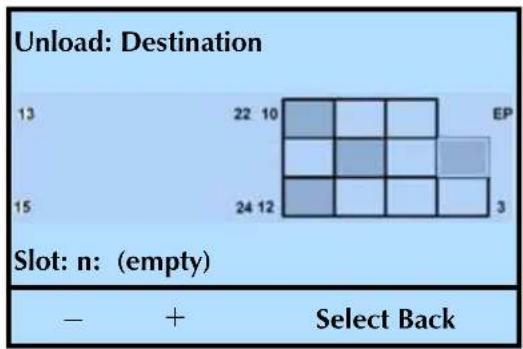
heatmap
Unload: Destination | 13 | 22 10 | EP | | :--- | :--- | :--- | | 15 | 24 12 | 3 | Slot: n: (empty) - + Select Back- Press OK to continue, or Back to cancel.
During the unload, the front panel displays an Unload Active message.
After a successful Unload, the library displays this confirmation message: Unload Good. Once the message appears, press OK to continue.
- Press Back (as needed) to return to the Home screen.
CLEANING THE TAPE DRIVE
Under normal operating conditions, the LTO Ultrium tape drive(s) installed in the library do not require regular cleaning. LTO Ultrium tape drives contain an automatic cleaning mechanism that allows them to clean themselves as necessary. Occasionally, a tape drive may require cleaning with a cleaning cartridge. LTO Ultrium tape drives monitor their cleaning needs internally and notify the library when they require cleaning.
Auto cleaning disabled—Clean the tape drive(s) whenever the library displays the "Needs Cleaning" message on the Home screen, or your application software notifies you. Not all backup applications display cleaning requirements.

text_image
TANDBERG DATA —— Storage Library T24 Lib : D-2 : D-1 : Needs Cleaning Move Lib Maint Drive▶ Auto cleaning enabled—The library does not display this message if Auto Cleaning is enabled and a cleaning cartridge is in the fixed cleaning cell. In this case, the cleaning is done automatically (see “Setting Up Automatic Tape Drive Cleaning” on page 63).

Caution
Do not use any cleaning method other than the LTO Cleaning Cartridge. Using other cleaning methods will void your warranty.
Carefully follow all instructions and recommendations provided with the cleaning cartridge. Do not rewind and reuse the material in a cleaning cartridge. Reusing the material may redistribute contaminants previously removed from the tape path. If all of the cleaning material has been used, discard the cartridge and use a new cleaning cartridge.
You can clean the tape drive(s) in several ways:
| To view this information... go to... | |
| Use the library's Autoclean function | page 135 |
| Use your backup application's cleaning option | |
| Use the front panel Clean Drive option |
CHECK THE CLEANING CARTRIDGE STATUS
Before cleaning the tape drive, verify that the cleaning cartridge in the library is not depleted.
Notes: The cleaning count information is stored in the cartridge, so it must be used once to "start" the count. Until it is used the first time, the library displays an "unknown" (Remote Management Utility) or "no data available" (front panel) status.
If there is no barcode label on the cleaning cartridge, a power cycle causes the cleaning count information to be lost. If there is a barcode label on the cleaning cartridge, the library stores the information and recognizes it after a power cycle.
To view the status of the cleaning cartridge after it has been used:
- At the Home screen, press Maint.
If necessary, enter the operator panel password (see page 80).
- Press ▼ until the selection arrow (▶) points to Cleaning Options.
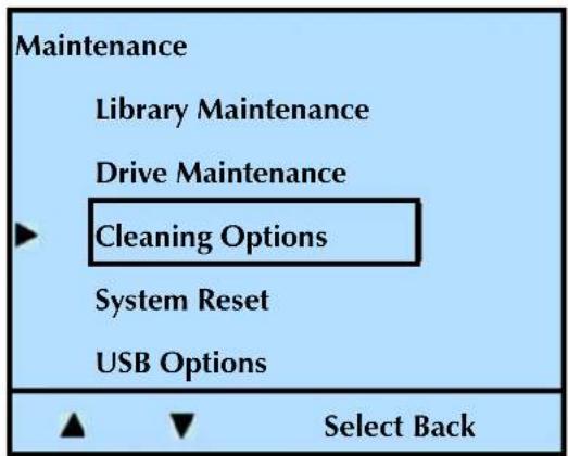
text_image
Maintenance Library Maintenance Drive Maintenance Cleaning Options System Reset USB Options Select Back-
Press Select.
-
Press ▼ until the selection arrow (▶) points to Cleaning Tape, and then press Select.
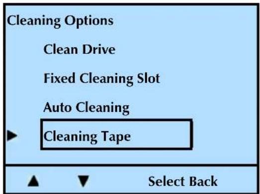
text_image
Cleaning Options Clean Drive Fixed Cleaning Slot Auto Cleaning Cleaning Tape Select BackThe library displays the number of cleanings left (if the count was previously started) or "No Data Available" (if the count was not previously started).
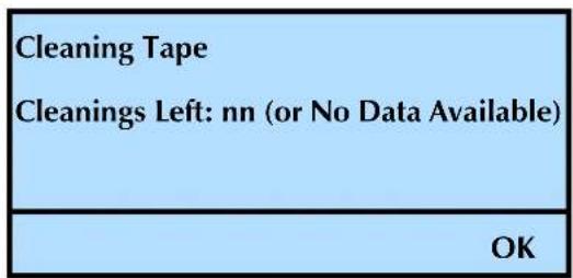
text_image
Cleaning Tape Cleanings Left: nn (or No Data Available) OK- Press Back (as needed) to return to the Home screen.
USE THE LIBRARY'S AUTOCLEAN FUNCTION
Set up automatic tape drive cleaning during library configuration, and store a cleaning cartridge in the library. See page 63 for information about setting up automatic tape drive cleaning.
| If the fixed cleaning slot is... | The library... |
| Enabled attempts to load a cleaning cartridge from the fixed cleaning cell | |
| Disabled looks for a cleaning cartridge in the I/E portOnce the cleaning cycle is complete, the cartridge will be returned to its original element (fixed cell or I/E port) | |
USE YOUR BACKUP APPLICATION'S CLEANING OPTION
Set the cleaning option in your backup application (if available) so that the software monitors tape drive cleaning requirements and automatically cleans the tape drive(s) using a cleaning cartridge stored in the library. Refer to your software documentation for information about setting this option.
CLEANING A TAPE DRIVE USING THE CLEAN DRIVE OPTION
Use the front panel Clean Drive option to clean the tape drive(s) when the library or backup application notifies you to do so. When you select the Clean Drive option, the library loads the cleaning cartridge into the tape drive, waits until the cleaning is finished, unloads the cleaning cartridge, returns it to its cell, and resumes normal operation.
Before using the Clean Drive option, make sure that you have turned the Auto Cleaning option OFF (see page 65).
The Clean Drive option allows you to select any slot/cell as the source for a cleaning cartridge, including an I/E Port. Determine the location of your cleaning cartridge, and then proceed.
| Cleaning Cartridge | Condition Description | |
| Not stored in library | Cells all occupied Use the Export command to remove a cartridge from the library, as described on page 126. Before closing the I/E Port door, insert the cleaning cartridge. | |
| Cells not all occupied Load the cleaning cartridge into an enabled I/E Port, and then select it as the “source” in Step 4 below. | ||
| Stored in library | I/E Port enabled Store in Slot/Cell 2 | |
| I/E Port disabled Store in Slot/Cell 1 | ||
When a tape drive requires cleaning:
- At the Home screen, press Maint.
If necessary, enter the operator panel password (see page 80).
- Press ▼ until the selection arrow (▶) points to Cleaning Options.
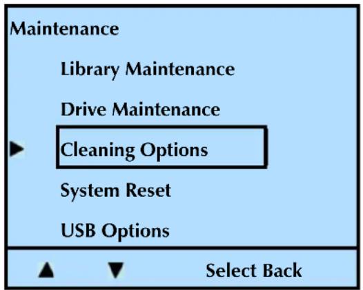
text_image
Maintenance Library Maintenance Drive Maintenance Cleaning Options System Reset USB Options Select Back- Press ▼ until the selection arrow (▶) points to Clean Drive, and then press Select.
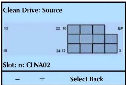
heatmap
Clean Drive: Source | Slot | n | Select Back | |---|---|---| | 13 | 13 | - | | 15 | 15 | - | | 22 | 22 | + | | 10 | 10 | + | | 24 | 24 | + | | 12 | 12 | + | | EP | EP | - | | 3 | 3 | - | The image contains a grid of squares representing the count of samples at each position. The label 'n: CLNA02' appears below the chart.- Press or to select the "source" slot where the cleaning cartridge is located (either a slot or the I/E Port), and then press Select.
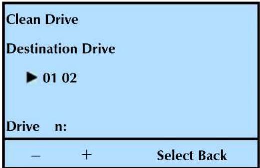
text_image
Clean Drive Destination Drive ► 01 02 Drive n: - + Select Back- Press or to toggle between tape drives (if more than one tape drive is installed), and then press Select.
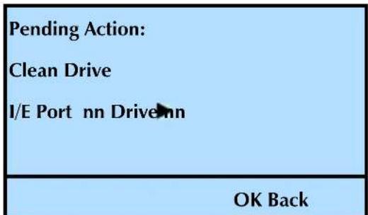
text_image
Pending Action: Clean Drive I/E Port nn Drive OK Back- Press OK to clean the tape drive, or Back to cancel the action.
! Important
If there are no more cleaning cycles remaining on the cleaning cartridge, the tape drive ejects the cartridge immediately without performing the cleaning. Remove the cleaning cartridge from the library and use a new one. Do not rewind and reuse the material in a cleaning cartridge. Reusing the material may redistribute contaminants previously removed from the tape path.
The tape drive automatically performs the cleaning in less than a minute and ejects the cartridge when finished.
During the cleaning, the front panel displays an Clean Drive Active message.
▶ After a successful cleaning, the library displays this confirmation message: Cleaning Good. Once the message appears, press OK to continue.
If the cleaning was not successful, a message explaining the failure appears on the screen. You may be prompted to insert a new cleaning cartridge.
If necessary, use the Export command to remove the cleaning cartridge from the library, as described on page 126. Before closing the I/E port door, insert the data cartridge you removed previously (if applicable). Then, firmly push the door closed.
- Press Back (as needed) to return to the Home screen.
RESETTING THE LIBRARY
If the library or tape drive has encountered an error and is not operating as expected after you have tried the recommended corrective actions, you may need to perform a reset.
Front panel reset—Instructions begin on page 139.
Back panel reset—You can reset both the library and the tape drive(s) by powering the library off and back on (press the 0 to power the library off, and then press the 1 to power the library back on).
Note: You may also be able to perform resets from your application software. Refer to your software documentation for instructions.
Resetting the library from the operator panel or powering the library off and back on causes it to perform its power-on self-test and a cartridge inventory. Powering the library off and back on to reset the tape drive(s) cause the tape drive to perform a power-on self-test and to rewind a loaded tape to the beginning.
! Important
If you need to power the library off, first unload the cartridge from the tape drive(s), if possible. If you power the library off and back on while a cartridge is in a tape drive, the tape drive may have to perform a lengthy format recovery process.
If a cartridge is loaded in a tape drive when the library is powered off and back on, the tape drive rewinds the tape but does not eject the cartridge. Make sure that it is safe to overwrite the tape before performing a backup so that you don't lose previously recorded data. If necessary, unload the cartridge as described on page 131.
Before resetting, make sure that the library or tape drive is not communicating across the bus. The reset may disrupt communications on the bus.
To reset the library from the operator panel:
- At the Home screen, press Maint.
If necessary, enter the operator panel password (see page 80).
- Press ▼ until the selection arrow (▶) points to System Reset.
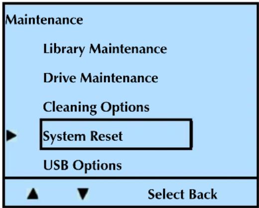
text_image
Maintenance Library Maintenance Drive Maintenance Cleaning Options System Reset USB Options Select Back3. Press Select.
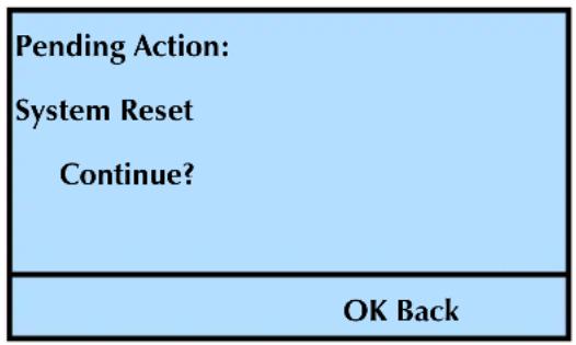
text_image
Pending Action: System Reset Continue? OK Back- Press OK to reset the library, or Back to cancel the action.
The time it takes the library to reset is based on the number of cartridges in the library and the number of cartridges without bar code labels. The library takes considerably longer to perform an inventory on cartridges without bar code labels.
- Press Back (as needed) to return to the Home screen.
STORING CARTRIDGES
Whenever you remove cartridges from your library, be sure to store them properly to maximize archival life and ensure data integrity. Follow these guidelines for proper cartridge storage:
Store cartridges in a suitable environment. Follow the specifications for storage temperature and other environmental requirements, as described on the cartridge packaging. Do not allow the temperature and humidity in the storage environment to fluctuate.
Store cartridges with the write-protect switch in the protected position.
If the switch... the tape is...
does not cover the opening write-enabled
covers the opening write-protected
Keep the storage location as free of airborne particulates as possible. To eliminate obvious sources of particulates, do not permit anyone to smoke, eat, or drink near the storage area, and do not store cartridges near a copier or printer that may emit toner and paper dust.
Store cartridges as soon as possible after you remove them from the library. Immediate storage helps avoid many of the conditions that can damage tapes, such as temperature and humidity fluctuations, particulate contamination, and excessive handling.
6
VIEWING LIBRARY INFORMATION
The library maintains an internal database containing extensive information about its configuration and operations. This information is available through the front panel. During day-to-day operation, you typically do not need to access this information. However, if you need to contact Tandberg Data Technical Support about your library, you may be asked to check and report back on various settings and event results.
This chapter explains how to view the following information.
| To view this information... go to... | |
| Library information – library type, serial number, and SCSI ID this page | |
| Library status – fans, cable, and temperature page 143 | |
| Library history – event logs page 144 | |
| Library statistics – view slots, drives, and I/E port page 146 | |
| Library settings – emulation mode, operation mode, ethernet, I/E port, and the display and storage settings | page 152 |
| Tape drive information –▪SCSI tape drive–serial number, SCSI ID, and type, and the tape drive designated as the SCSI interface (bridge)▪FC tape drive–NPort Address, Loop ID, Port number, and WWNN number | page 153 |
| Cartridge inventory page 158 | |
VIEWING BASIC LIBRARY INFORMATION
Because the library communicates with the host through the SCSI interface of the tape drive(s) via the ADI serial interface, the SCSI interface seen by the host is the SCSI interface (SCSI ID) of the tape drive.
All instructions begin at the library's Home screen.
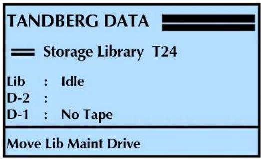
text_image
TANDBERG DATA —— Storage Library T24 Lib : Idle D-2 : D-1 : No Tape Move Lib Maint DriveTo check the library's basic information:
- At the Home screen, press Lib.
If necessary, enter the operator panel password (see page 80).
- Press ▼ until the selection arrow (▶) points to Library ID.
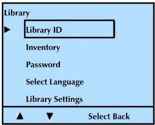
text_image
Library ► Library ID Inventory Password Select Language Library Settings ▲ ▼ Select Back- Press Select.
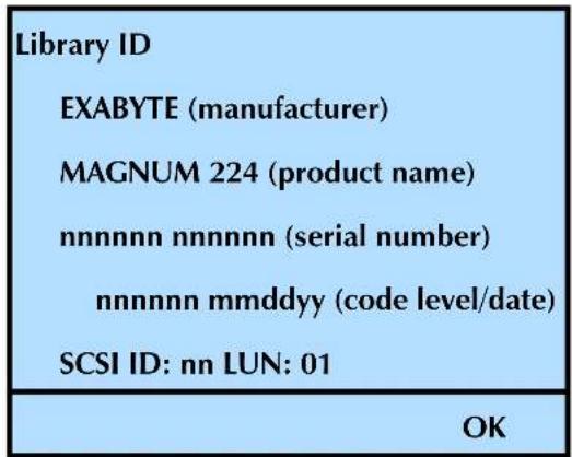
text_image
Library ID EXABYTE (manufacturer) MAGNUM 224 (product name) nnnnnn nnnnnn (serial number) nnnnnn mmddyy (code level/date) SCSI ID: nn LUN: 01 OK| Important | Because the library uses the ADI serial interface, the SCSI ID indicates the ID of the tape drive.The library appears to the host as LUN1 of the SCSI ID of the tape drive.See the tape drive’s Product Manual and the Automation/Drive Interface - Command (ADC) for more information. |
- Press OK.
- Press Back (as needed) to return to the Home screen.
VIEWING LIBRARY STATUS
To check the library's status:
- At the Home screen, press Maint.
If necessary, enter the operator panel password (see page 80).
- Press ▼ until the selection arrow (▶) points to Library Maintenance.
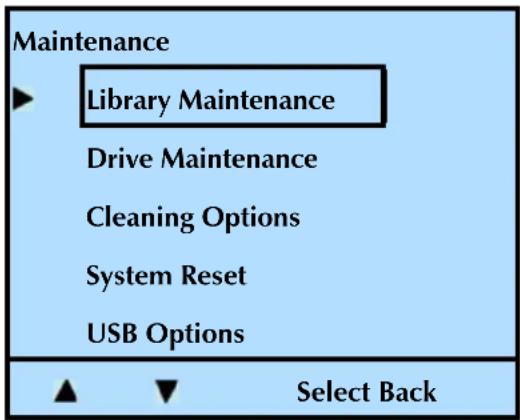
text_image
Maintenance ► Library Maintenance Drive Maintenance Cleaning Options System Reset USB Options ▲ ▼ Select Back-
Press Select.
-
Press ▼ until the selection arrow (▶) points to Library Status.
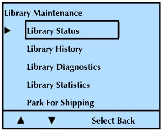
text_image
Library Maintenance ► Library Status Library History Library Diagnostics Library Statistics Park For Shipping ▲ ▼ Select Back- Press Select. A screen similar to this one appears.
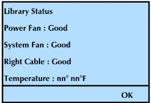
text_image
Library Status Power Fan : Good System Fan : Good Right Cable : Good Temperature : nn° nn°F OK-
Press OK.
-
Press Back (as needed) to return to the Home screen.
VIEWING LIBRARY HISTORY
The library history (sometimes called the event log) lists any events that prevented a library operation from completing (up to four events). If you contact Tandberg Data Technical support, you may be asked to check this history buffer to help troubleshoot a problem. The most recent event appears first.
The library displays the event logs in this format:
| Example history screen Definition | |
| Library History Page Title | |
| #1 History entry number | |
| Move Medium Command that failed | |
| Servo Failure Type of error | |
| Slot: 1 | Primary slot involved |
| Power time: 1234567890 | Cumulative power-on time (minutes) |
To view the library's history:
- At the Home screen, press Maint.
If necessary, enter the operator panel password (see page 80).
- Press ▼ until the selection arrow (▶) points to Library Maintenance.
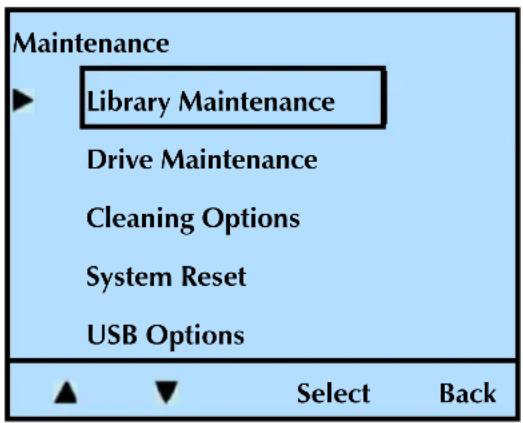
text_image
Maintenance ► Library Maintenance Drive Maintenance Cleaning Options System Reset USB Options ▲ ▼ Select Back-
Press Select.
-
Press ▼ until the selection arrow (▶) points to Library History.
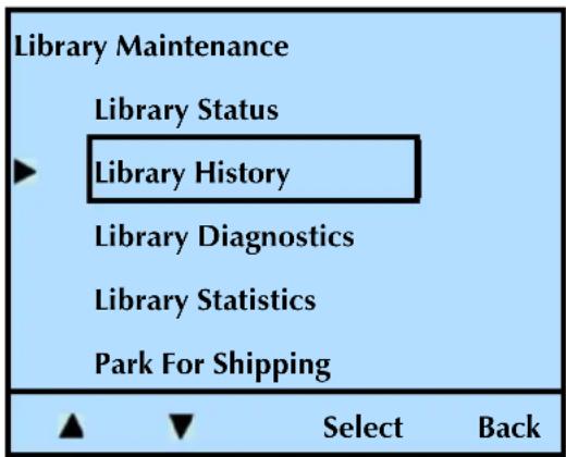
text_image
Library Maintenance Library Status ► Library History Library Diagnostics Library Statistics Park For Shipping ▲ ▼ Select Back- Press Select. A screen similar to the following one appears (Library History #0).
| Library History #0: Command Drive communication Slot: n Power Time: 1234567890 |
| Next Back |
- Press Next to view the next screen (Library History #1).
| Library History #1: Command Servo Failure Slot: n Power Time: 1234567890 |
| Next Back |
Note: Continue pushing the "Next" button to cycle through the remaining Library History screens.
- Press Back (as needed) to return to the Home screen.
VIEWING LIBRARY STATISTICS
The library's statistics menu provides you with information on the slots, the tape drive(s), and the I/E port.
VIEWING SLOTS
- At the Home screen, press Maint.
If necessary, enter the operator panel password (see page 80).
- Press ▼ until the selection arrow (▶) points to Library Maintenance.
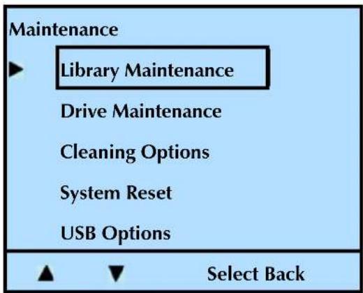
text_image
Maintenance ► Library Maintenance Drive Maintenance Cleaning Options System Reset USB Options ▲ ▼ Select Back-
Press Select.
-
Press ▼ until the selection arrow (▶) points to Library Statistics.
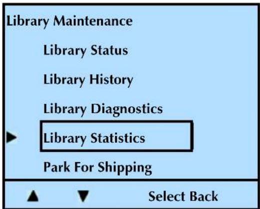
text_image
Library Maintenance Library Status Library History Library Diagnostics Library Statistics Park For Shipping Select Back- Press Select, and then press ▼ until the selection arrow (▶) points to View Slots.
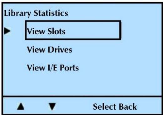
text_image
Library Statistics View Slots View Drives View I/E Ports Select Back- Press Select. A screen similar to this one appears. In this example, slot 8 is highlighted. Press +or to move through the slots.
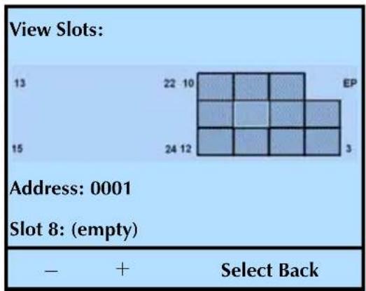
heatmap
| Row | Column | Value | |---|---|---| | 13 | 1 | 13 | | 13 | 2 | 22 - 10 | | 13 | 3 | 15 | | 13 | 4 | 24 - 12 | | 13 | 5 | 3 | | 13 | 6 | 22 - 10 | | 13 | 7 | 15 | | 13 | 8 | 24 - 12 | | 13 | 9 | 15 | | 13 | EP | 1 | | 13 | 10 | 22 - 10 | | 13 | 11 | 15 | | 13 | 12 | 24 - 12 | | 13 | 13 | 3 | | 13 | 14 | 22 - 10 | | 13 | 15 | 15 | | 13 | 16 | 24 - 12 | | 13 | 17 | 15 | | 13 | 18 | 24 - 12 | | 13 | 19 | 3 | | 13 | EP | 1 | | 13 | 20 | 22 - 10 | | 13 | 21 | 15 | | 13 | 22 | 24 - 12 | | 13 | 23 | 15 | | 13 | 24 | 24 - 12 | | 13 | 25 | 3 | | 13 | EP | 1 | | 13 | 26 | 22 - 10 | | 13 | 27 | 15 | | 13 | 28 | 24 - 12 | | 13 | 29 | 15 | | 13 | EP | 3 | | 13 | EP | 2 | | 13 | EP | 1 | | 13 | EP | 2 | | 13 | EP | 1 | | EP | EP | 2 | | EP | EP | 3 | | EP | EP | 4 | | EP | EP | 5 | | EP | EP | 6 | | EP | EP | 7 | | EP | EP | 8 | | EP | EP | 9 | | EP | EP | 10 | | EP | EP | 11 | | EP | EP | 12 | | EP | EP | 13 | | EP | EP | 14 | | EP | EP | 15 | | EP | EP | 16 | | EP | EP | 17 | | EP | EP | 18 | | EP | EP | 19 | | EP | EP | 20 | | EP | EP | 21 | | EP | EP | 22 | | EP | EP | 23 | | EP | EP | 24 | | EP | EP | 25 | | EP | EP | 26 | | EP | EP | 27 | | EP | EP | 28 | | EP | EP | 29 | | EP | EP | 30 | | EP | EP | Select Back Address:0001 Slot8:(empty) - + Select BackNote: The screen above shows the library with only one magazine installed.
- Press Back (as needed) to return to the Home screen.
VIEWING TAPE DRIVE(S)
- At the Home screen, press Maint.
If necessary, enter the operator panel password (see page 80).
- Press ▼ until the selection arrow (▶) points to Library Maintenance.
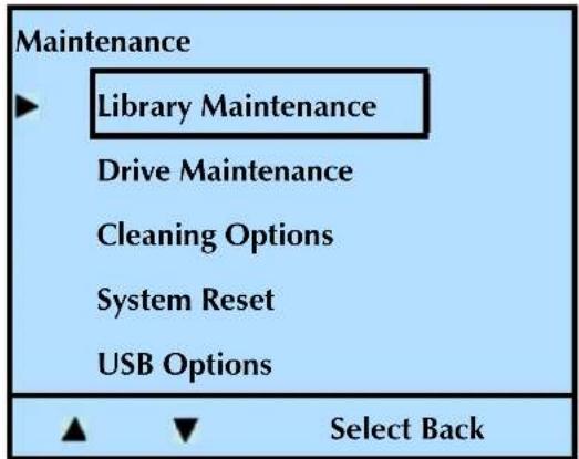
text_image
Maintenance ► Library Maintenance Drive Maintenance Cleaning Options System Reset USB Options ▲ ▼ Select Back-
Press Select.
-
Press ▼ until the selection arrow (▶) points to Library Statistics.
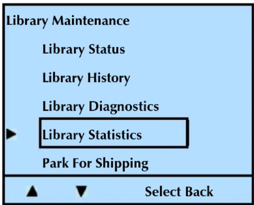
text_image
Library Maintenance Library Status Library History Library Diagnostics Library Statistics Park For Shipping Select Back- Press Select. Press ▼ until the selection arrow (▶) points to View Drives.
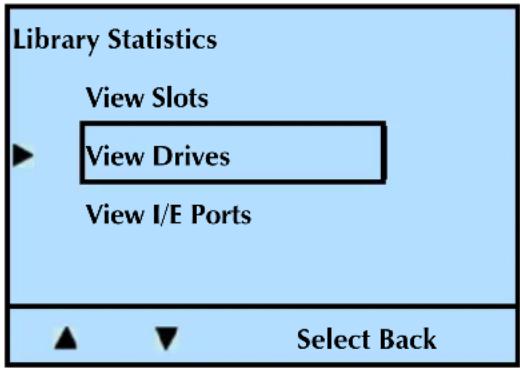
text_image
Library Statistics View Slots View Drives View I/E Ports Select Back- Press Select. A screen similar to the following one appears.
Press +or to advance through the tape drives (if more than one tape drive is installed in the library).
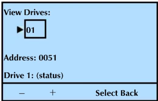
text_image
View Drives: ►01 Address: 0051 Drive 1: (status) - + Select BackNote: The screen above shows the library with only one tape drive installed.
- Press Select. A screen similar to this one appears.
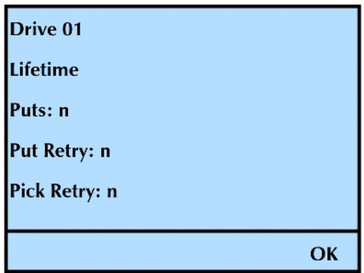
text_image
Drive 01 Lifetime Puts: n Put Retry: n Pick Retry: n OK- Press OK.
- Press Back (as needed) to return to the Home screen.
VIEWING THE I/E PORT
- At the Home screen, press Maint.
If necessary, enter the operator panel password (see page 80).
- Press ▼ until the selection arrow (▶) points to Library Maintenance.
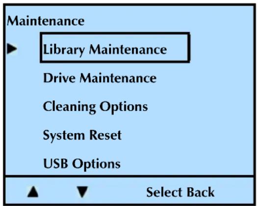
text_image
Maintenance ► Library Maintenance Drive Maintenance Cleaning Options System Reset USB Options ▲ ▼ Select Back-
Press Select.
-
Press ▼ until the selection arrow (▶) points to Library Statistics.
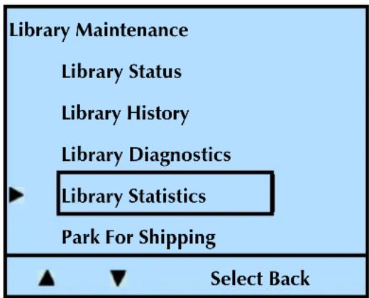
text_image
Library Maintenance Library Status Library History Library Diagnostics Library Statistics Park For Shipping Select Back- Press Select. Press ▼ until the selection arrow (▶) points to View I/E Ports.
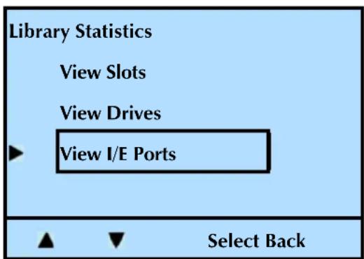
text_image
Library Statistics View Slots View Drives View I/E Ports Select Back- Press Select. A screen similar to this one appears.
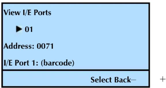
text_image
View I/E Ports ► 01 Address: 0071 I/E Port 1: (barcode) Select Back— +- Press Select. A screen similar to this one appears.
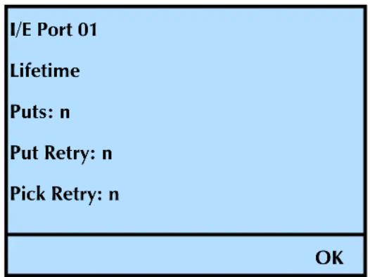
text_image
I/E Port 01 Lifetime Puts: n Put Retry: n Pick Retry: n OK- Press OK.
- Press Back (as needed) to return to the Home screen.
VIEWING LIBRARY SETTINGS
You may need to access the library settings before performing some of the maintenance procedures described in Chapter 7.
To view the library's settings:
- At the Home screen, press Lib.
If necessary, enter the operator panel password (see page 80).
- Press ▼ until the selection arrow (▶) points to Library Settings.
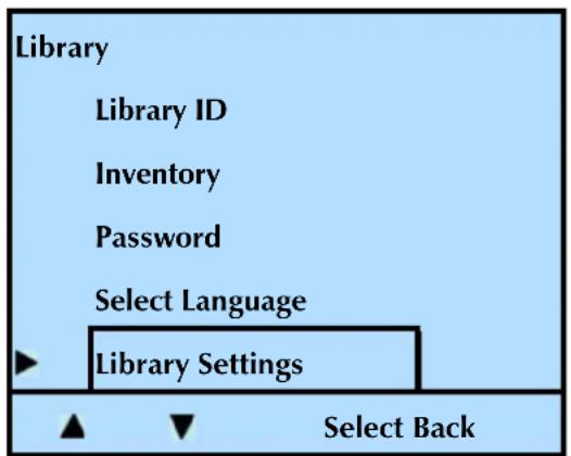
text_image
Library Library ID Inventory Password Select Language Library Settings Select Back-
Press Select.
-
Press until the selection arrow () points to the setting that you wish to view.
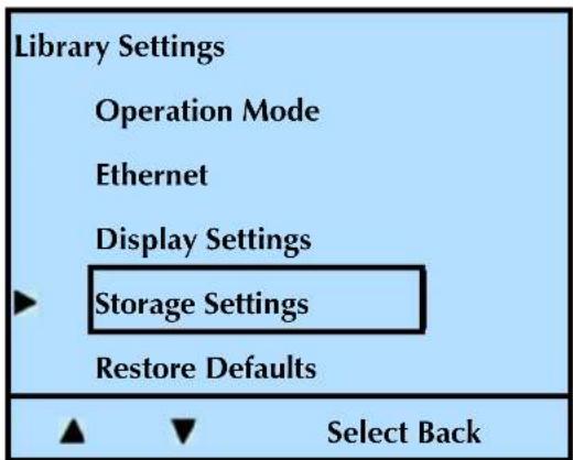
text_image
Library Settings Operation Mode Ethernet Display Settings Storage Settings Restore Defaults Select Back-
Press Select.
-
Repeat these steps to view the library's settings.
| To change the... See... | ||
| Emulation mode page 57 | ||
| Operation mode (Random or Sequential) page 59 | ||
| Ethernet settings | page 67 | |
| Display settings | page 42 | |
| Storage settings (slot count) (I/E port enabling) | page 47 page 49 | |
| To restore the default settings | page 83 | |
- Press Back (as needed) to return to the Home screen.
VIEWING BASIC TAPE DRIVE INFORMATION
LVD SCSI TAPE DRIVE—BRAND AND SERIAL NUMBER
To check a tape drive's type and serial number:
- At the Home screen, press Drive.
If necessary, enter the operator panel password (see page 80).
- Press ▼ until the selection arrow (▶) points to Drive ID.
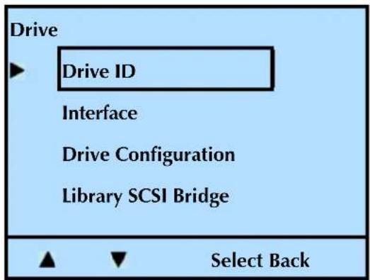
text_image
Drive ► Drive ID Interface Drive Configuration Library SCSI Bridge ▲ ▼ Select Back- Press Select.
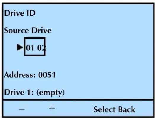
text_image
Drive ID Source Drive ►01 02 Address: 0051 Drive 1: (empty) - + Select Back- Press or to toggle between tape drives (if more than one tape drive is installed), and then press Select.
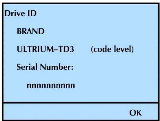
text_image
Drive ID BRAND ULTRIUM-TD3 (code level) Serial Number: nnnnnnnnnnn OK-
Press OK.
-
Press Back (as needed) to return to the Home screen.
LVD SCSI OR FIBRE CHANNEL TAPE DRIVE—INTERFACE
To view a tape drive's interface information:
- At the Home screen, press Drive.
If necessary, enter the operator panel password (see page 80).
- Press ▼ until the selection arrow (▶) points to Interface.
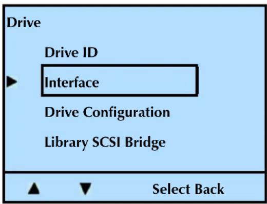
text_image
Drive Drive ID ► Interface Drive Configuration Library SCSI Bridge Select Back- Press Select.
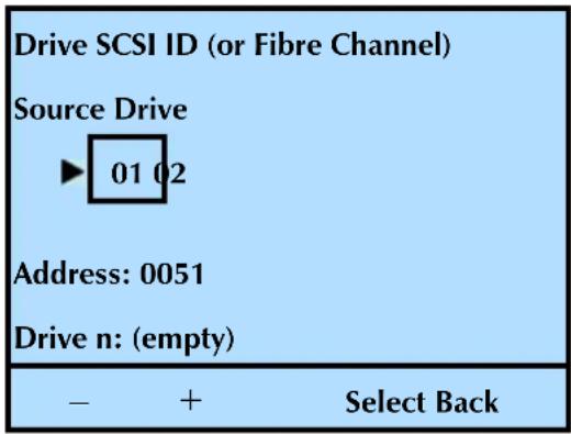
text_image
Drive SCSI ID (or Fibre Channel) Source Drive ► 01 02 Address: 0051 Drive n: (empty) - + Select Back- Press or to toggle between tape drives (if more than one tape drive is installed), and then press Select.
SCSI Tape Drive
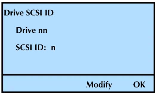
text_image
Drive SCSI ID Drive nn SCSI ID: n Modify OKFibre Channel Tape Drive
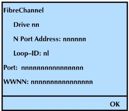
text_image
FibreChannel Drive nn N Port Address: nnnnnn Loop-ID: nl Port: nnnnnnnnnnnnnnnnn WWNN: nnnnnnnnnnnnnnnnn OK5. Press OK.
Note: See “Changing the SCSI IDs” on page 52 for instructions on how to change the tape drive SCSI IDs.
6. Press Back (as needed) to return to the Home screen.
To check a tape drive's serial number:
- At the Home screen, press Drive.
If necessary, enter the operator panel password (see page 80).
- Press ▼ until the selection arrow (▶) points to Drive Configuration.
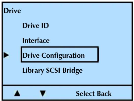
text_image
Drive Drive ID Interface ► Drive Configuration Library SCSI Bridge Select Back3. Press Select.
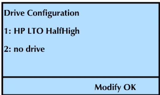
text_image
Drive Configuration 1: HP LTO HalfHigh 2: no drive Modify OKNote: See "Tape Drive Configuration" on page 55 for instructions on how to change the library's tape drive configuration.
4. Press OK.
- Press Back (as needed) to return to the Home screen.
TAPE DRIVE SCSI BRIDGE INTERFACE
If you have two tape drives installed in the library, you can assign one of them to act as the primary SCSI interface (bridge) for the library. If you have only one tape drive installed, it automatically acts as the SCSI bridge.
For instructions on how to assign one of the tape drives to act as the SCSI interface (bridge), see “Tape Drive SCSI Interface (Library Bridge)” on page 54.
Note: The library communicates with the host through the SCSI interface of the tape drive(s) via the ADI serial interface. The SCSI interface as seen by the host is the SCSI interface of the tape drive.
See the tape drive Product Manual for tape drive information. See Automation/Drive Interface - Command (ADC) for ADI information.
To check a tape drive's SCSI interface (bridge) assignment:
1. At the Home screen, press Drive.
If necessary, enter the operator panel password (see page 80).
- Press ▼ until the selection arrow (▶) points to Library SCSI Bridge.
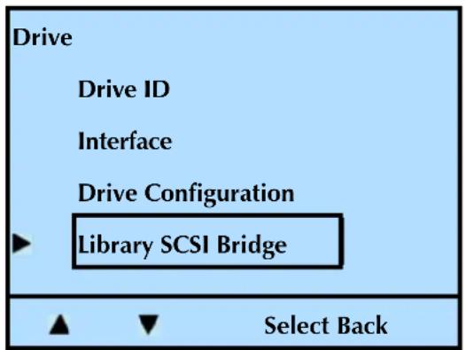
text_image
Drive Drive ID Interface Drive Configuration Library SCSI Bridge Select Back- Press Select.

text_image
Library SCSI Bridge Drive: nn Modify OK-
Press OK.
-
Press Back (as needed) to return to the Home screen.
VIEWING AND UPDATING THE CARTRIDGE INVENTORY
The library maintains a cartridge inventory to keep track of where cartridges are located. In performing an inventory, the library checks for cartridges in the cells and scans each cartridge's bar code label. The library uses this information to process commands from an application.
VIEWING CARTRIDGE INVENTORY
A cartridge inventory is automatically performed each time the library is powered on, each time a cartridge is inserted or removed from the library, and each time a magazine is inserted into the library. You can view the cartridge inventory to quickly determine which cells contain cartridges and whether a cartridge is loaded in a tape drive.
Magazine inventory (slots)
To view the magazine inventory:
- At the Home screen, press Lib.
If necessary, enter the operator panel password (see page 80).
- Press ▼ until the selection arrow (▶) points to Inventory.
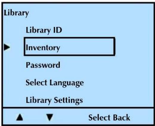
text_image
Library Library ID Inventory Password Select Language Library Settings ▲ ▼ Select Back-
Press Select.
-
Press ▼ until the selection arrow (▶) points to View Slots.
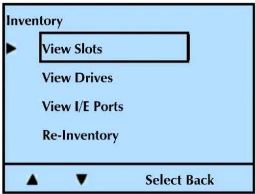
text_image
Inventory View Slots View Drives View I/E Ports Re-Inventory Select Back- Press Select.
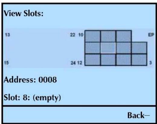
heatmap
| Row | Column | Value | |---|---|---| | 13 | 22 | 10 | | 13 | 10 | | | 13 | | | | 13 | | | | 13 | | | | 13 | | | | 13 | | | | 13 | | | | 13 | | | | 13 | | | | 13 | | | | 13 | | | | 13 | | | | 13 | 15 | | | 13 | 24 | 12 | | 13 | 12 | | | 13 | 3 | | | 13 | EP | | | 13 | EP | | | 13 | EP | | | 13 | EP | | | 13 | EP | | | 13 | EP | | | 13 | EP | | | 13 | EP | | | 13 | EP | | | 13 | EP | | | 13 | EP | | | 13 | EP | | | 13 | EP | | | Address: 0008 Slot: 8: (empty) Back-Notes: The slot/cell count changes depending on whether you have the I/E Port and the fixed cleaning slot enabled or disabled. If there is no cartridge in the slot/cell that you are viewing, the library indicates an (empty) status.
If you enabled the Media Identifier (see "Enabling the Media Identifier" on page 50), the library also displays the type of cartridge (LTO-2, LTO-3, and so forth). The library scans the bar code label, not the cartridge, so if you affix an LTO-2 bar code label to an LTO-3 data cartridge, it displays as an LTO-2 cartridge.
- Press or to move between the slots.
This moves the cursor to the next (or previous) occupied slot and shows the slot number and the barcode number (if there is a cartridge and it has a barcode). The library skips slots that do not contain a cartridge.
- Press Back (as needed) to return to the Home screen.
Tape drive inventory
To view a tape drive's inventory:
- At the Home screen, press Lib.
If necessary, enter the operator panel password (see page 80).
- Press ▼ until the selection arrow (▶) points to Inventory.
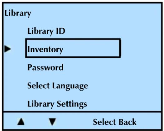
text_image
Library Library ID Inventory Password Select Language Library Settings ▲ ▼ Select Back-
Press Select.
-
Press ▼ until the selection arrow (▶) points to View Drives.
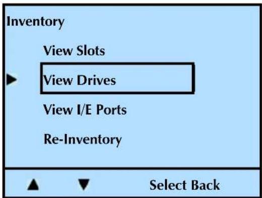
text_image
Inventory View Slots View Drives View I/E Ports Re-Inventory Select Back- Press Select.
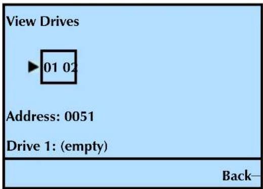
text_image
View Drives ►01 02 Address: 0051 Drive 1: (empty) Back—+
Notes: If there is no cartridge in the tape drive that you are viewing, the library indicates an (empty) status. If the tape drive contains a cartridge, the library lists the bar code information.
- Press or to toggle between the tape drives (if you have two tape drives installed).
- Press Back (as needed) to return to the Home screen.
I/E port inventory
To view the I/E port inventory:
- At the Home screen, press Lib.
If necessary, enter the operator panel password (see page 80).
- Press ▼ until the selection arrow (▶) points to Inventory.
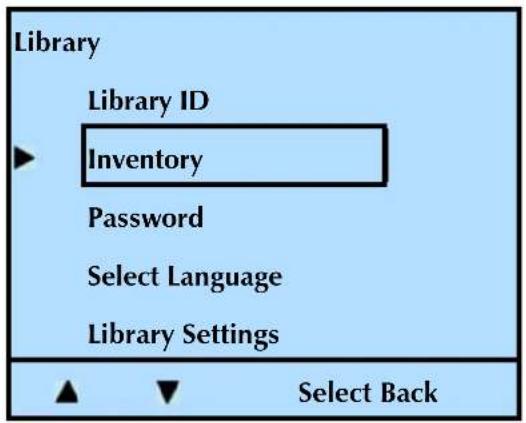
text_image
Library Library ID Inventory Password Select Language Library Settings ▲ ▼ Select Back-
Press Select.
-
Press ▼ until the selection arrow (▶) points to View I/E Ports.
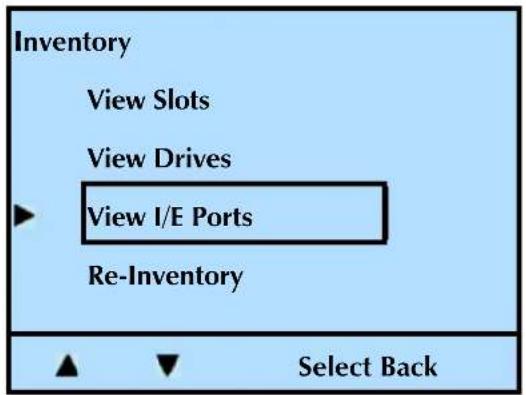
text_image
Inventory View Slots View Drives View I/E Ports Re-Inventory Select Back- Press Select.
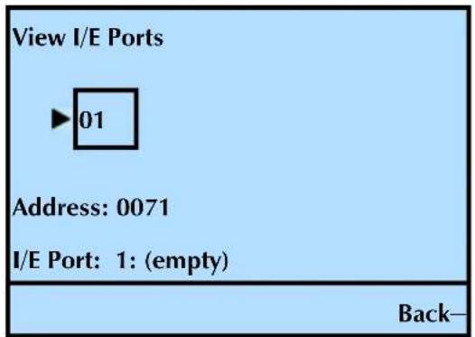
text_image
View I/E Ports ►01 Address: 0071 I/E Port: 1: (empty) Back—Notes: If there is no cartridge in the I/E Port, the library indicates an (empty) status. If the I/E Port contains a cartridge, the library lists the bar code.
If the I/E Port is not enabled, the following screen appears:
| View I/E Ports No Enabled I/E Port |
| OK |
- Press Back (as needed) to return to the Home screen.
UPDATING THE CARTRIDGE INVENTORY
Although the library maintains its cartridge inventory automatically, you can issue an operator panel command to update the inventory at any time. For example, you might want to update the inventory if the bar code scanner has had a problem reading a bar code label. If the bar code label screen indicates all blanks for a label, you may want to have the library re-do the cartridge inventory to see if it can read the label. If the problem still exists, you may need to replace the label.
To update the cartridge inventory, see "Issuing a Re-inventory Command to the Library" on page 128.
NOTES
7
MAINTENANCE
This chapter describes basic library maintenance tasks that you can perform on-site without the aid of a service technician.
| To view this information... go to... | ||
| Installing or replacing a tape drive (begins on this page) | page 165 | |
| Removing cartridges without power – from the library or tape drive | page 181 | |
| Cleaning the library page 183 | ||
| Tape drive diagnostics – running a self test page 183 | ||
| Library diagnostics – running system tests and demos page 185 | ||
| Upgrading library firmware | using FTP page 192 | |
| using LibTool page 193 | ||
| using the USB port page 193 | ||
| Creating library diagnostic listings | Using FTP | page 192 |
| using the USB port page 194 | ||
| Upgrading tape drive firmware and creating diagnostic listings | using LTOTool | page 196 |
| Upgrading tape drive firmware using the USB port page 196 | ||

Caution
Do not attempt to replace any components in the library, other than the tape drive. If you do so, you will void your warranty.
INSTALLING OR REPLACING A TAPE DRIVE
This section describes how to install or replace a tape drive in the library. Please read Preparing for Installation or Replacement, the General Information section, and the entire section that you are using prior to beginning the procedure.
PREPARING FOR INSTALLATION OR REPLACEMENT
Note: If your library is installed in a rack, it is not necessary to remove the library from the rack to complete this procedure. It is also not necessary to disconnect the Ethernet cable from the back of the library.
√ Obtain these items—a #2 Phillips screwdriver and a small flat-blade screwdriver.
√Ensure that the environment is free of conditions that could cause electrostatic discharge (ESD)—If possible, use an antistatic mat and a grounded static protection wristband during installation. If a mat and wristband are not available, touch a known grounded surface, such as a computer's metal chassis.
| Warning | Before performing any installation or maintenance procedures, be sure that the library's power switch is off and that the power cord is disconnected from the library and the outlet. |
| Warnung | Vor der Ausführung von Installations- oder Wartungsarbeiten ist darauf zu achten, daß der Library-Netzschalter auf "Aus" gestellt ist und daß das Anschlußkabel vom Library und der Steckdose entfernt ist. |
| Advertencia | Antes de realizar cualquier procedimiento de instalación o de mantenimiento, comprobar que el interruptor de alimentación de la biblioteca está apagado y que el cable de alimentación no está enchufado ni a la biblioteca ni a la toma de corriente. |
GENERAL INFORMATION
The StorageLibrary T24 will accommodate Ultrium 3 (LTO-3) or Ultrium 2 (LTO-2) tape drives in half height (HH) or full height (FH) configurations. The library does not accommodate LTO-1 tape drives.
! Important
The tape drives must be specially configured (at the factory) for use in a StorageLibrary T24 library. Purchase tape drive kits only from Tandberg Data or Tandberg Data-approved suppliers.
| To view this information... go to... | |
| Adding a second half height tape drive page 169 | |
| Replacing a tape drive with the same configuration (half height -to- half height or full height -to- full height) | page 171 |
| Replacing a half height tape drive with a full height tape drive | page 175 |
| Reconfiguring the library(this step must be completed for the library to operate) | page 178 |
| Resuming operation page 179 | |
| Confirming the installation page 180 |
Note: Most of the illustrations show SCSI configurations. Use the same steps to install Fibre Channel tape drives.
REFERENCE ILLUSTRATIONS
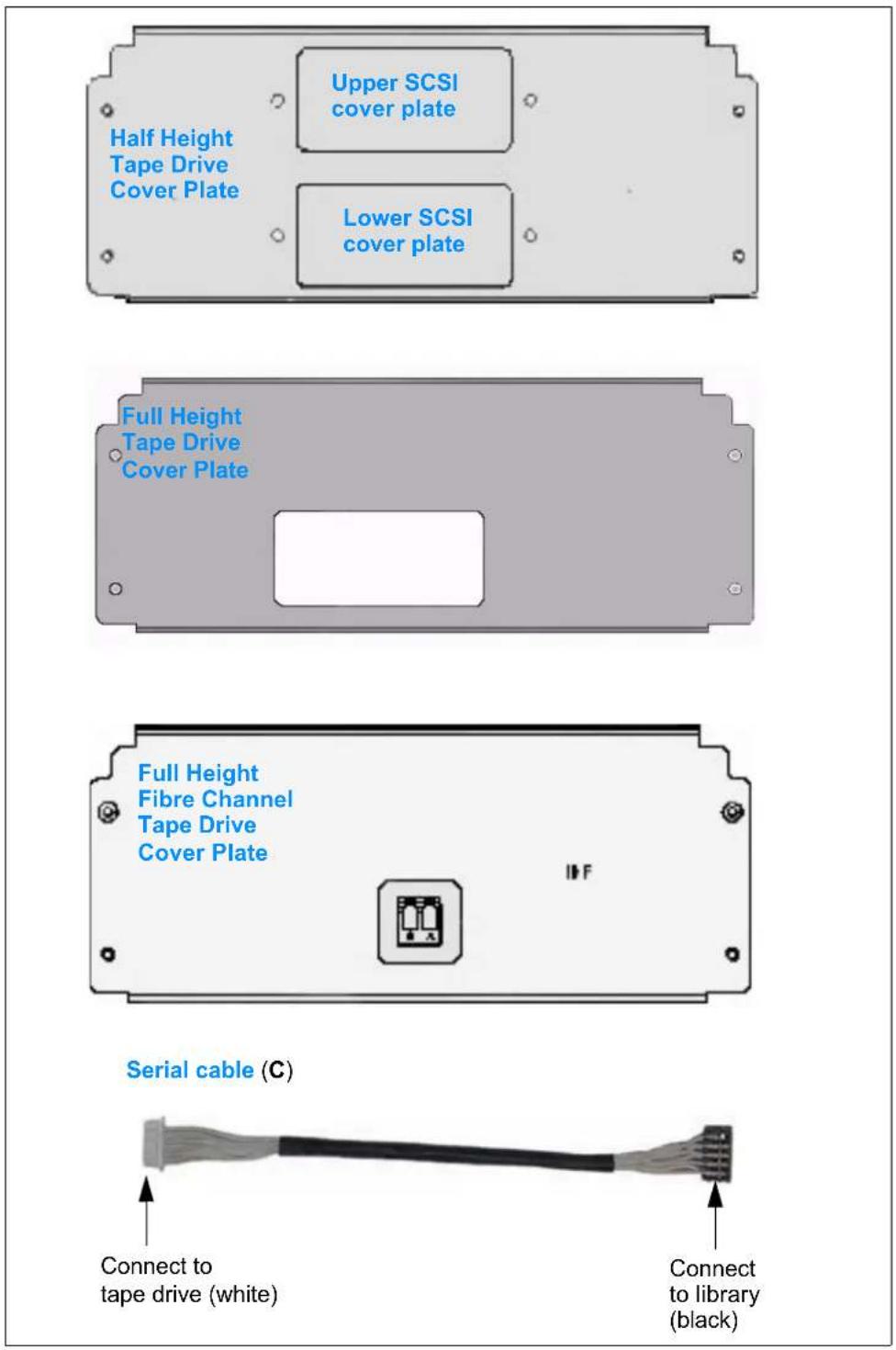
text_image
Upper SCSI cover plate Half Height Tape Drive Cover Plate Lower SCSI cover plate Full Height Tape Drive Cover Plate Full Height Fibre Channel Tape Drive Cover Plate Serial cable (C) Connect to tape drive (white) Connect to library (black)Important
Be sure to use the serial cable (S) that came with your replacement kit. The serial cables are specifically configured (at the factory) for use with the individual tape drives.
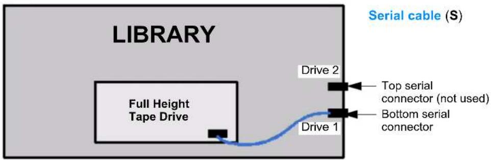
text_image
LIBRARY Serial cable (S) Full Height Tape Drive Drive 2 Top serial connector (not used) Bottom serial connector Drive 1Figure 7-1 Serial cable routing—full height tape drive
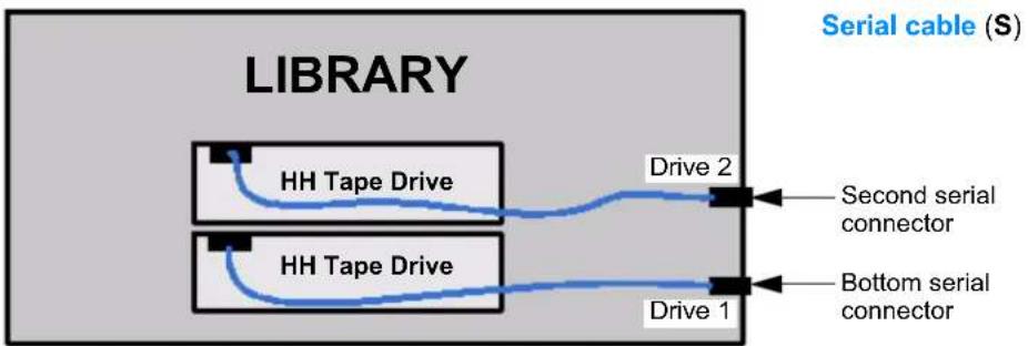
text_image
LIBRARY HH Tape Drive Drive 2 Second serial connector HH Tape Drive Drive 1 Bottom serial connector Serial cable (S)Figure 7-2 Serial cable routing—half height tape drives
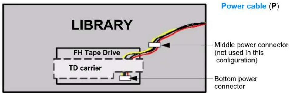
text_image
LIBRARY Power cable (P) FH Tape Drive TD carrier Middle power connector (not used in this configuration) Bottom power connectorFigure 7-3 Power cable routing—full height tape drive
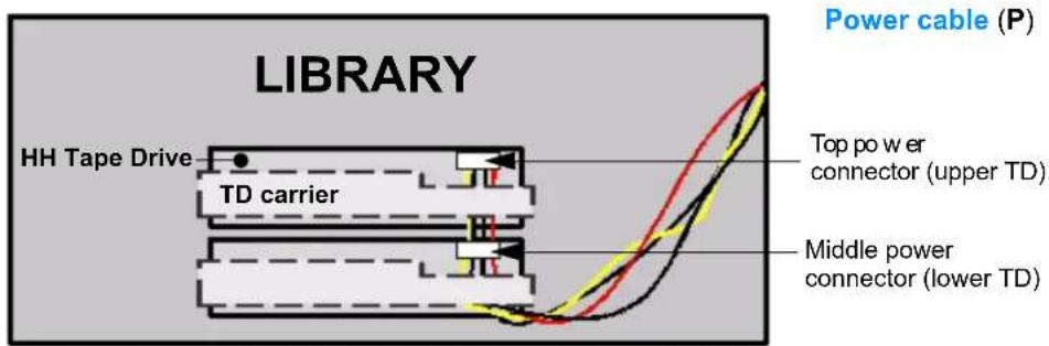
text_image
LIBRARY HH Tape Drive TD carrier Power cable (P) Top power connector (upper TD) Middle power connector (lower TD)Figure 7-4 Power cable routing—half height tape drives
INSTALLING A SECOND HALF HEIGHT TAPE DRIVE
To install an additional tape drive, follow these steps:
1. Preparing for replacement—
a.Power off the host.
b. Power off the library (press the 0 on the back of the unit).
c. Disconnect the power cord, the SCSI or Fibre Channel cable(s), and the terminator (if one is installed).
d. Remove the tape drive cover plate. Set the plate and the screws aside.
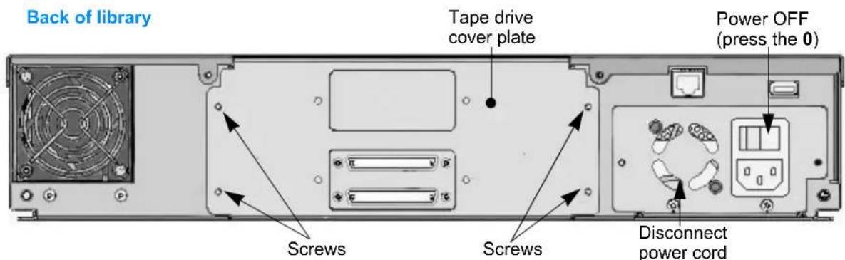
text_image
Back of library Tape drive cover plate Power OFF (press the 0) Screws Screws Disconnect power cordFigure 7-5 Tape drive cover plate (half height SCSI library)
Note: The above figure shows the SCSI library. Remove the Fibre Channel tape drive cover plate the same way.
2. Removing the cooling plate and disconnecting the cables—
a. Remove the two screws ( A) holding the tape drive cooling plate ( B). Remove the plate, and discard it and the screws.
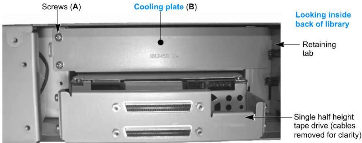
text_image
Screws (A) Cooling plate (B) Looking inside back of library Retaining tab Single half height tape drive (cables removed for clarity)Figure 7-6 Tape drive cooling plate
b. Disconnect the power cables (P) from the installed tape drive.
3. Installing the tape drive—
a. Locate the serial cable (S) that came in your replacement kit and attach it to the appropriate serial connector inside the library. Route the cables as shown in Figure 7-2 and Figure 7-7.
| Tape drive Quantity | Install in this opening... | Serial connector | Internal label | |
| Half height | Second tape drive | Top | Top | Drive 2 |
| Single tape drive | Bottom | Bottom | Drive 1 | |
b. While holding the cables to the side, slide the new tape drive directly into the library, leaving it a short distance out to access the cables. Use care not to damage the cables.
c. Connect the supplied serial cable (S) and the power cable (P) to the tape drives.
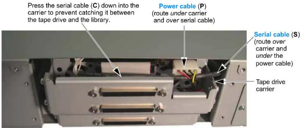
text_image
Press the serial cable (C) down into the carrier to prevent catching it between the tape drive and the library. Power cable (P) (route under carrier and over serial cable) Serial cable (S) (route over carrier and under the power cable) Tape drive carrierFigure 7-7 Upper half height tape drive cable routing
d.Slide the tape drive the remaining distance into the library.
4. Completing the installation—
a. Locate the tape drive cover plate (see "Reference Illustrations" on page 167). First, remove the SCSI plate, and then attach the tape drive cover plate with the screws you removed earlier.
| ! Important | The library requires both the SCSI cover plates and the tape drive cover plates for ESD protection. Do not leave any openings uncovered.Do not connect the SCSI cables until after you reconfigure the library. |
b. Reconfigure your library—You must reconfigure your library for your backup application to recognize the new tape drive. See page 178 for instructions.
REPLACING A TAPE DRIVE (SAME CONFIGURATION)
To replace a tape drive with a different tape drive of the same configuration (half height to half height, or full height to full height), follow these steps.
1. Preparing for replacement—
a.Power off the host.
b. Power off the library (press the 0 on the back of the unit).
c.Disconnect the power cord, the SCSI or Fibre Channel cable(s), and the terminator (if present).
d. Remove the tape drive cover plate. Set the plate and the screws aside.
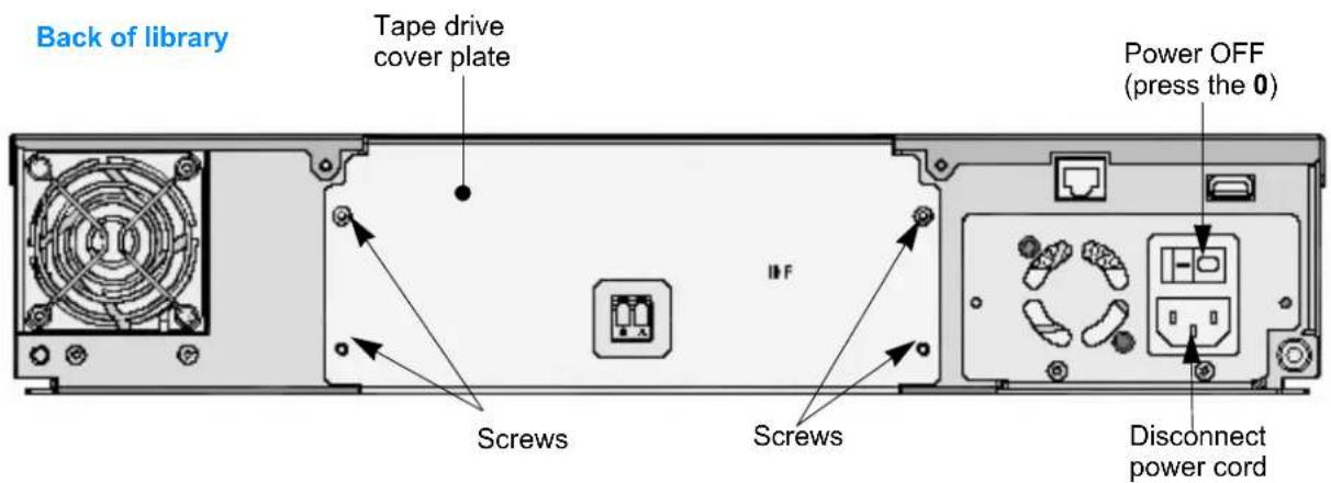
text_image
Back of library Tape drive cover plate Power OFF (press the 0) IFF Screws Screws Disconnect power cordFigure 7-8 Tape drive cover plate (Fibre Channel library)
2. Removing the tape drive—
a. Pull the tape drive a short distance out of the library, and then disconnect the serial cables (S) from the tape drive(s) that you are replacing.
b.Disconnect the power cables ( P ) from all of the tape drives.
c. While holding the cables out of the way, pull the tape drive straight out of the library.

Caution
Be certain to support the tape drive as you remove it from the library. LTO Ultrium tape drives weigh several pounds each.
d. Disconnect the 10-pin serial cable from the library and discard it. Do not reuse the serial cable.
3. Installing the new tape drive—
a. Locate the serial cable (S) that came in your replacement kit and attach it to the appropriate serial connector inside the library. Full height tape drive—see Figure 7-1 Half height tape drive—see Figure 7-2
b. While holding the cables out of the way, slide the new tape drive into the library, leaving it a short distance out to access the cables. Use care not to damage the cables.
| Tape drive Quantity | Install in this opening... | Serial connector | Internal label | |
| Half height | Second tape drive | Top | Top | Drive 2 |
| Single tape drive | Bottom | Bottom | Drive 1 | |
| Full height | Single tape drive | Bottom | Bottom | Drive 1 |
c. Connect the supplied serial cable (S) and the power cable (P) to the tape drive. For routing instructions, see:
▶ Full Height tape drive on page 173
Second Half height tape drive on page 173
▶ Single Half height tape drive on page 174
Full height tape drive:
Serial—Route the serial cable (S) under the tape drive carrier as shown here; connect as shown in Figure 7-1 (FH serial cable routing).
Power—Route the power cable over the tape drive carriers as shown here; connect as shown in Figure 7-3 (FH power cable routing).
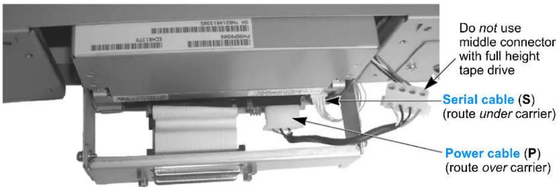
text_image
Do not use middle connector with full height tape drive Serial cable (S) (route under carrier) Power cable (P) (route over carrier)Figure 7-9 Full height tape drive's serial and power connectors
Second Half height tape drive: Install the tape drive in the upper opening. Serial—Route the serial cable (S) over the tape drive carrier and under the power cable; connect as shown in Figure 7-2 (HH serial cable routing).
Power—Route the power cable under the tape drive carrier as shown here; connect as shown in Figure 7-4 (HH power cable routing).
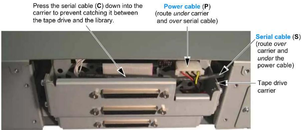
text_image
Press the serial cable (C) down into the carrier to prevent catching it between the tape drive and the library. Power cable (P) (route under carrier and over serial cable) Serial cable (S) (route over carrier and under the power cable) Tape drive carrierFigure 7-10 Upper half height tape drive cable routing
Single Half height tape drive: Install the tape drive in the lower opening, and use the middle power connector (P).
Serial—Route the serial cable (S) over the tape drive carrier and under the power cable; connect as shown in Figure 7-2 (HH serial cable routing).
Power—Route the power cable under the tape drive carrier as shown here; connect as shown in Figure 7-4 (HH power cable routing).

text_image
Serial connector (S) (route under power cable) Power cable (P) (use middle connector) Route both cables over tape drive carrier Second half height power connector (do not use with only one HH tape drive installed)Figure 7-11 Lower half height tape drive cable routing
d.Slide the tape drive the remaining distance into the library. Use care not to damage the cables during this step.
4. Completing the installation—
a. Attach the SCSI cover plate and the tape drive cover plate that came with your replacement kit. See "Reference Illustrations" on page 167.
| Tape drive Quantity | Install in this opening... | Serial connector | Internal label | |
| Half height | Second tape drive | Top | Top | Drive 2 |
| Single tape drive | Bottom | Bottom | Drive 1 | |
| Full height | Single tape drive | Bottom | Bottom | Drive 1 |
! Important
The library requires both the SCSI cover plates and the tape drive cover plates for ESD protection. Do not leave any openings uncovered.
Do not connect the SCSI cables until after you reconfigure the library.
b. Reconfigure your library—You must reconfigure your library for your backup application to recognize the new tape drive. See page 178 for instructions.
REPLACING A TAPE DRIVE (HALF HEIGHT TO FULL HEIGHT)
To replace the half height tape drive in your library (or both half height tape drives) with a full height tape drive, follow these steps.
1. Preparing for replacement—
a.Power off the host.
b. Power off the library (press the 0 on the back of the unit).
c. Disconnect the power cord, the SCSI or Fibre Channel cable(s), and the terminator (if present).
d. Remove the tape drive cover plate. Set the plate and the screws aside.
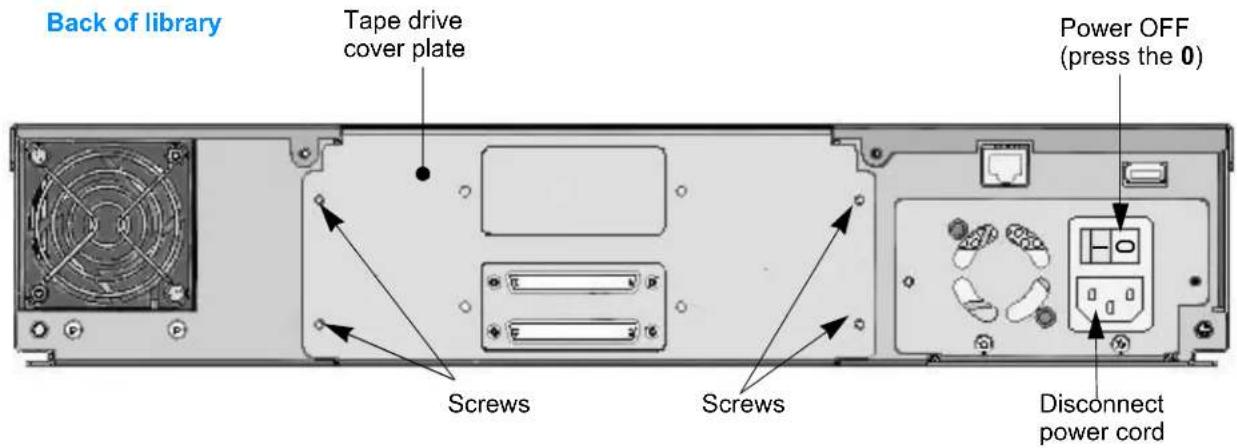
text_image
Back of library Tape drive cover plate Power OFF (press the 0) Screws Screws Disconnect power cordFigure 7-12 Tape drive cover plate (half height SCSI library)
2. Removing the cables, cooling plates, and tape drives—
a. Pull the tape drive a short distance out of the library and disconnect the serial cable (S).
b. Disconnect the power cables (P) from all of the tape drives.
c. Remove the screws (A) holding the tape drive cooling plate (B) if one is installed. Remove the plate, and discard it and the screws.
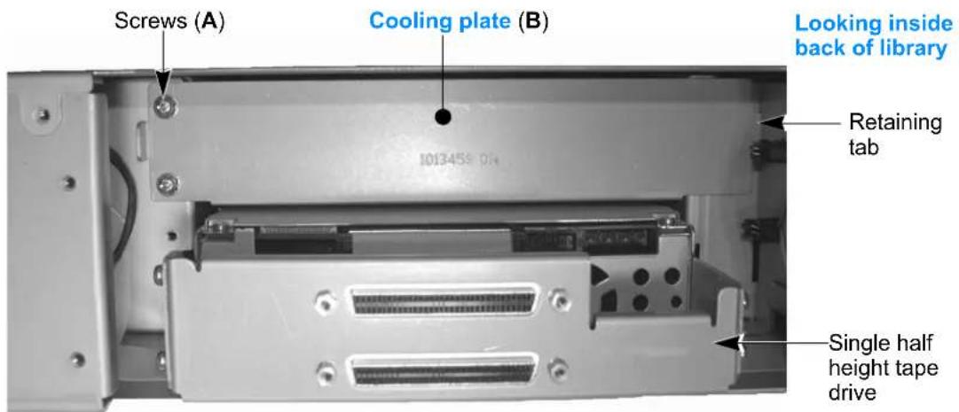
text_image
Screws (A) Cooling plate (B) Looking inside back of library Retaining tab Single half height tape driveFigure 7-13 Tape drive cooling plate
d. While holding the cables out of the way, remove the tape drive.

Caution
Be certain to support the tape drive as you remove it from the library. LTO Ultrium tape drives weigh several pounds each.
Repeat steps as necessary to remove the second tape drive, if one is installed.
e.Disconnect the serial cable (S) from the library. Do not reuse this cable. If you are replacing multiple tape drives, remove and discard the serial cables from all the tape drives you are replacing.
3. Installing the tape drive—
a. Locate the serial cable ( S ) that came in your replacement kit and attach it to the appropriate serial connector inside the library. Full height tape drive—see Figure 7-1
b. While holding the cables to the side, slide the new tape drive directly into the library, leaving it a short distance out to access the cables. Use care not to damage the cables.
c. Connect the supplied serial cable (S) and the power cable (P) to the tape drives.
Serial—Route the serial cable (S) under the tape drive carrier as shown here; connect as shown in Figure 7-1 (FH serial cable routing).
Power—Route the power cable over the tape drive carrier as shown here; connect as shown in Figure 7-3 (FH power cable routing).
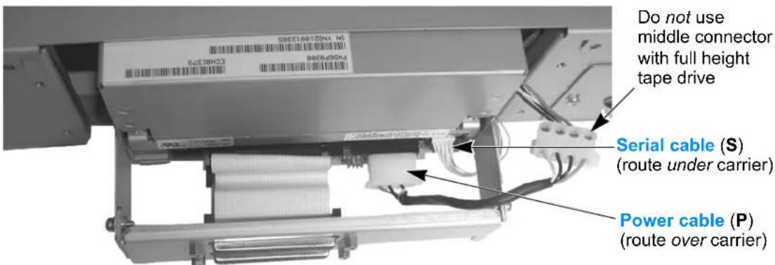
text_image
Do not use middle connector with full height tape drive Serial cable (S) (route under carrier) Power cable (P) (route over carrier)Figure 7-14 Full height tape drive's serial and power connectors
d.Slide the tape drive the remaining distance into the library.
4. Completing the installation—
a. Attach the SCSI cover plates and the tape drive cover plate that came with your replacement kit. See "Reference Illustrations" on page 167.
| Tape drive Quantity | Install in this opening... | Serial connector | Internal label | |
| Full height | Single tape drive | Bottom | Bottom | Drive 1 |
! Important
The library requires both the SCSI cover plates and the tape drive cover plates for ESD protection. Do not leave any openings uncovered.
Do not connect the SCSI cables until after you reconfigure the library.
b. Reconfigure your library—You must reconfigure your library for your backup application to recognize the new tape drive. See page 178 for instructions.
RECONFIGURING THE LIBRARY AND RESUMING OPERATION
RECONFIGURING THE LIBRARY
In order for the library to recognize the new tape drive, you must set the tape drive configuration to match the tape drives that are installed in the library.
Note: Do not connect the SCSI cables at this time.
To set tape drive configuration:
- At the Home screen, press Drive.
If necessary, enter the operator panel password (see page 80).
- Press ▼ until the selection arrow (▶) points to Drive Configuration.
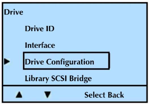
text_image
Drive Drive ID Interface ► Drive Configuration Library SCSI Bridge ▲ ▼ Select Back- Press Select.
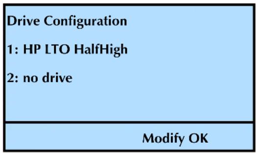
text_image
Drive Configuration 1: HP LTO HalfHigh 2: no drive Modify OKNote: The library lists “no drive” only if there is no room for more tape drives. For example, in the above screen, the library has one half height tape drives. The two tape drive number is for two half height tape drives.
- Press Modify. Press ▼ or ▲ until the selection arrow (▶) points to the desired configuration. Press Select.
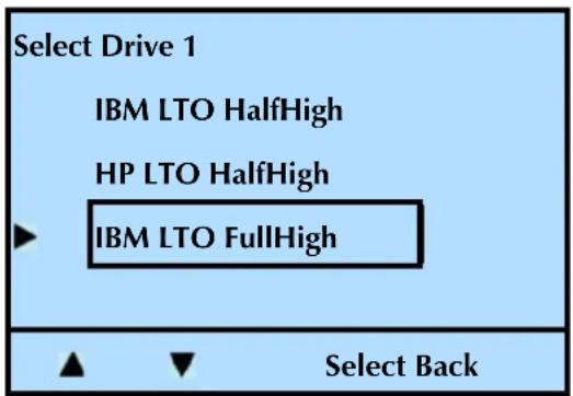
text_image
Select Drive 1 IBM LTO HalfHigh HP LTO HalfHigh IBM LTO FullHigh Select BackNotes: This menu option requires input for all of the tape drives installed in the library. If you press "Back" before configuring all the tape drives, the configuration selection will not change.
- Press OK.
- Repeat the process for each tape drive installed.
- Press Back (as needed) to return to the Home screen.
RESUMING OPERATION
- Power the library off (Press the 0 on the back of the unit—after setting the new tape drive configuration).
- Connect the interface cables.
a. Connect the Fibre Channel cable (or cables if you installed more than one Fibre Channel tape drive).
or...
b. Connect the SCSI cable (or cables if you installed more than one tape drive) and a terminator (if needed).
! Important
Both LTO-2 and LTO-3 SCSI tape drives require an Ultra 3 or LVD 160 terminator to function properly on the SCSI bus. An inadequate terminator will result in various SCSI bus issues, including bus hangs and Read/Write failures. See “Tape Drive Fails with Sporadic Errors” on page 203.
Notes: You must install a terminator on the device at the physical end of the SCSI bus. If one of the tape drives in the library terminates the SCSI bus, you must install the required terminator on one of the tape drive's SCSI connectors.
If there are additional devices on the SCSI bus, ensure that only the device at the physical end of the bus is terminated.
The library communicates with the host through the SCSI interface of one of the tape drive via the Automation Drive Interface (ADI) serial interface.
See the tape drive's Product Manual for tape drive information.
IBM — www.storage.ibm.com/tape/lto/oem/index.html
Hewlett Packard — www1.hp.com/storage/tapestorage.html
See Automation/Drive Interface for ADI information: www.T10.org
- Reconnect the power cord and power on the library (press the I on the back of the unit), and then power on the host.
The library is now ready to resume operation. The new tape drive defaults to the following SCSI IDs:
| Tape Drive Configuration SCSI ID | ||
| Single half height tape drive 3 | ||
| Two half height tape drives | Upper tape drive 4 | |
| Lower tape drive 3 | ||
| Full height tape drive 3 | ||
! Important
You may need to reconfigure your backup application to recognize the new tape drive. Refer to your application's documentation for instructions.
CONFIRMING THE INSTALLATION
You may want to perform a few load and unload operations and back up several megabytes of data to ensure that the library and the newly installed tape drive (or tape drives) are communicating correctly.
| Use LibTool to | Detect the library |
| View the library's cartridge inventory | |
| Move tapes into and out of the tape drive | |
| Use LTOTool to | Detect the tape drive |
| Perform a Read/Write test |
Download and install the tools from www.tandbergdata.com. The readme file that accompanies the program (or the online help for the Windows version) provides instructions for using the tools.
For questions regarding software configuration, operation (including how to perform a backup operation), or installation—contact your software provider.
REMOVING CARTRIDGES WITHOUT POWER
If you need to remove cartridges from the library when power is unavailable, either due to a general power failure or a failure of the library's power supply, use one of these methods.
REMOVING A MAGAZINE WITHOUT LIBRARY POWER

Caution
This method is for EMERGENCY magazine removal only. If you are unsure if the robot was idle when the power went out, be aware that there is a chance that the robot was moving a cartridge into or out of the magazine. If so, the magazine will not manually eject, and you should not use force. Contact Tandberg Data Technical Support if you encounter this situation (see “Contacting Tandberg Data Corporation” on page iii).
To remove a magazine without library power:
-
If your library is installed in a rack, disengage the screws securing the rails to the back of the rack, and slide the library forward approximately six inches to expose the access slots in the side of the library (see "Attaching the Library to the Rails" on page 16).
-
Insert the tip of a small flat-blade screwdriver into the bottom of the small slot and gently lift up to disengage the locking mechanism (see Figure 7-15). Each side of the library has an access slot—one for each magazine. The magazine will disengage and move a short distance out of the library.
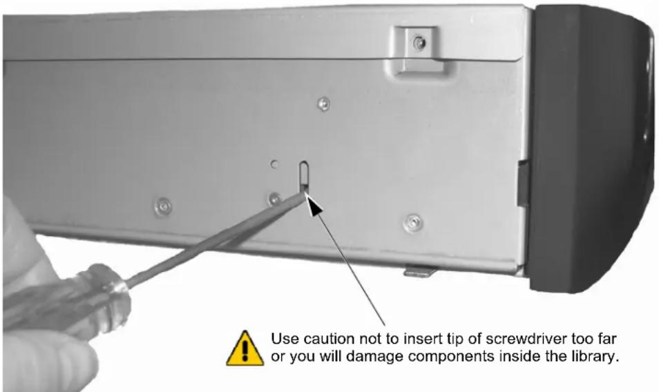
text_image
Use caution not to insert tip of screwdriver too far or you will damage components inside the library.Figure 7-15 Manual magazine release
Note: Use caution handling a magazine that is loaded with cartridges. Each cartridge weighs over 12 lb. (0.24 kg) each. Fully loaded, each magazine will weigh approximately 8.8 lbs. (4.0 kg).
- Pull the magazine straight out of the library. Use caution not to move the magazine up or down, or from side to side as you pull it out of the library. This could cause damage to components inside the library.
REMOVING A CARTRIDGE FROM THE TAPE DRIVE
If a cartridge is loaded in a tape drive when power to the library fails and you need to remove that cartridge, you must first remove the tape drive from the library (see "Installing or Replacing a Tape Drive" on page 165 for instructions).
If the library's power supply failed, you can attach the tape drive to another power source, such as an available power connector in a server and use the tape drive's unload button to remove the cartridge.
If a general power failure occurred, contact Tandberg Data Technical Support (see page iii) for information about removing the cartridge from the tape drive manually.
CLEANING THE LIBRARY

Caution
The library's internal components are lubricated at the factory and should not be cleaned or relubricated.
The only library components that should be cleaned are the tape drive and the operator panel.
▶ Instructions for cleaning the tape drive are provided on page 135.
To clean the LCD (the operator panel), use wipes or cleaners appropriate for LCD screens or computer monitors.

Caution
To avoid scratching the LCD, do not use abrasive cleaners, abrasive cleaning implements, harsh chemicals, or solvents.
RUNNING TAPE DRIVE DIAGNOSTICS
You may want to perform diagnostics on your tape drive(s) to troubleshoot problems. The library offers a tape drive self test.
To perform a tape drive self test:
- At the Home screen, press Maint.
If necessary, enter the operator panel password (see page 80). - Press ▼ until the selection arrow (▶) points to Drive Maintenance.
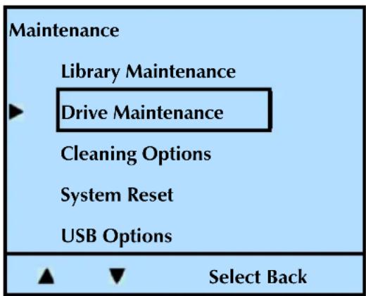
text_image
Maintenance Library Maintenance Drive Maintenance Cleaning Options System Reset USB Options Select Back-
Press Select.
-
Press ▼ until the selection arrow (▶) points to Drive Diagnostics.
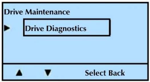
flowchart
graph TD
    A["Drive Maintenance"] --> B["Drive Diagnostics"]
    B --> C["Select Back"]
-
Press Select.
-
Press ▲ or ▼ until the selection arrow (▶) points to Drive Self Test.
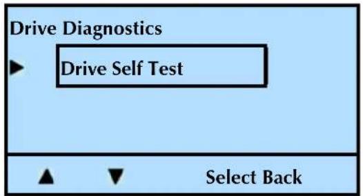
text_image
Drive Diagnostics ► Drive Self Test ▲ ▼ Select Back- Press Select.
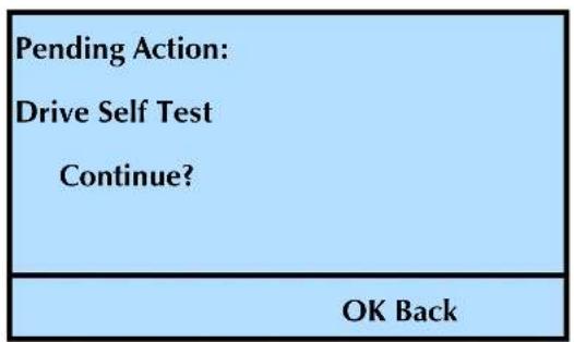
text_image
Pending Action: Drive Self Test Continue? OK Back-
Press OK to perform the test.
-
Press Back (as needed) to return to the Home screen.
RUNNING LIBRARY DIAGNOSTICS
To check basic library functions, you can run a set of diagnostic tests from the operator panel. These tests check the library's electronics and SCSI functions. If you report a problem to Tandberg Data Technical Support, you may be asked to run these tests and provide the results.
PERFORMING A DIGITAL SELF TEST
To perform a digital self test on the library:
- At the Home screen, press Maint.
If necessary, enter the operator panel password (see page 80).
- Press ▼ until the selection arrow (▶) points to Library Maintenance.
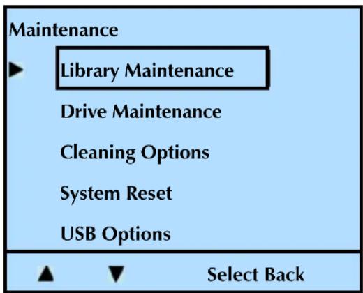
text_image
Maintenance ► Library Maintenance Drive Maintenance Cleaning Options System Reset USB Options ▲ ▼ Select Back- Press Select, and then press ▼ until the selection arrow (▶) points to Library Diagnostics.
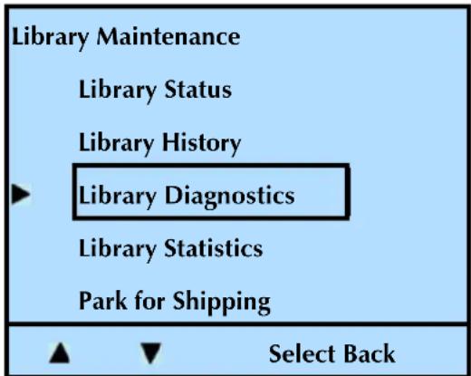
text_image
Library Maintenance Library Status Library History ► Library Diagnostics Library Statistics Park for Shipping ▲ ▼ Select Back- Press Select, and then press ▼ until the selection arrow (▶) points to Digital Self Test.
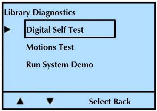
text_image
Library Diagnostics ► Digital Self Test Motions Test Run System Demo ▲ ▼ Select Back- Press Select.
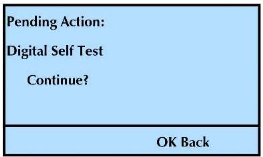
text_image
Pending Action: Digital Self Test Continue? OK Back- Press OK to perform the test.
- Press Back (as needed) to return to the Home screen.
PERFORMING A MOTION TEST
To perform a motion test on the library:
- At the Home screen, press Maint.
If necessary, enter the operator panel password (see page 80).
- Press ▼ until the selection arrow (▶) points to Library Maintenance.
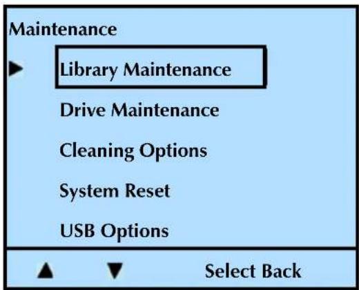
text_image
Maintenance ► Library Maintenance Drive Maintenance Cleaning Options System Reset USB Options ▲ ▼ Select Back- Press Selection press ▼ until the selection arrow (▶) points to Library Diagnostics.
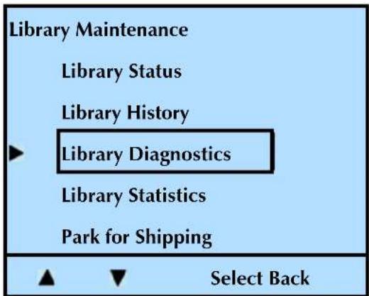
text_image
Library Maintenance Library Status Library History Library Diagnostics Library Statistics Park for Shipping Select Back- Press Select, and then press ▼ until the selection arrow (▶) points to Motions Test.
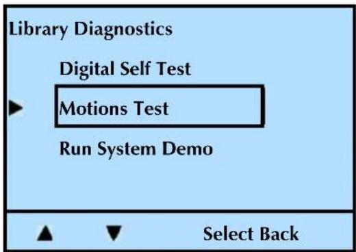
text_image
Library Diagnostics Digital Self Test Motions Test Run System Demo Select Back5. Press Select.
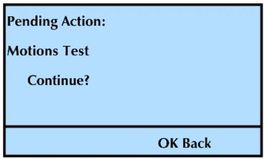
text_image
Pending Action: Motions Test Continue? OK Back6. Press OK to perform the test.
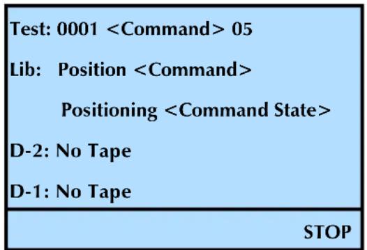
text_image
Test: 0001Press STOP at any time to cancel the test.
7. Press Back (as needed) to return to the Home screen.
RUNNING A SYSTEM DEMO
The library has a built-in demo program that can be used for testing or demonstrating library operation. When performing its demo program, the library loops through the following functions:
▶ Moves the robot to a cell
If the cell contains a cartridge, the library moves the cartridge to the tape drive.
If the cell does not contain a cartridge, the library moves the robot to a cell that contains a cartridge.
If the Load option (described in this chapter) is on, the library:
- Inserts the cartridge into a tape drive
- Waits for the tape drive to load the tape
▶ Instructs the tape drive to unload and eject the cartridge
Returns the cartridge to its cell
▶ Repeats the above functions until any front panel button is pushed To run a system demo on the library:
- At the Home screen, press Maint.
If necessary, enter the operator panel password (see page 80).
- Press ▼ until the selection arrow (▶) points to Library Maintenance.
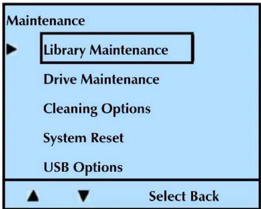
text_image
Maintenance ► Library Maintenance Drive Maintenance Cleaning Options System Reset USB Options ▲ ▼ Select Back- Press Select, and then press ▼ until the selection arrow (▶) points to Library Diagnostics.
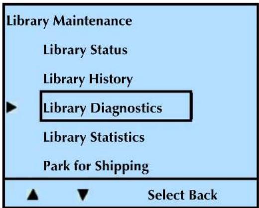
text_image
Library Maintenance Library Status Library History Library Diagnostics Library Statistics Park for Shipping Select Back-
Press Select.
-
Press ▼ until the selection arrow (▶) points to Run System Demo.
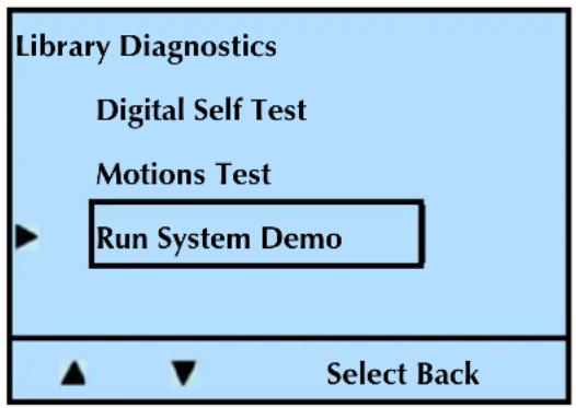
text_image
Library Diagnostics Digital Self Test Motions Test ▶ Run System Demo Select BackNote: You have the option of running the demo with the Load Drive option enabled or disabled. Select the desired mode and continue.
- Press Select.
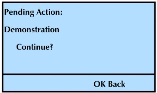
text_image
Pending Action: Demonstration Continue? OK Back- Press OK to perform the test.
To stop the demo, press the Stop button. The Home screen is displayed.
Note: If a cartridge is in the tape drive when you stop the demo, the cartridge is unloaded.
Press Back (as needed) to return to the Home screen.
FTP—LIBRARY FIRMWARE UPGRADE AND DIAGNOSTICS
Occasionally, Tandberg Data may make revisions to the library's internal code (firmware). The library's Remote Management utility contains additional firmware for the Ethernet module. The Ethernet firmware may also be revised periodically.
You can download new firmware from www.tandbergdata.com. To upload new firmware to the library, you can use the library's optional Ethernet interface and an FTP utility.
If you report a problem to Tandberg Data Technical Support, you may be asked to create a diagnostic listing (also called a dump) via FTP. A diagnostic listing is created when you use an FTP utility to send a copy of the library's diagnostic buffer to a host computer. This information can be used by support personnel to troubleshoot incidents with the library.
This section describes how to connect the library to a host computer and use an FTP utility to upgrade library firmware and create diagnostic listings.
Note: If you don't want to use the library's Remote Management utility, see page 193 for information about using LibTool to upgrade firmware over the SCSI interface.
CONNECTING TO THE LIBRARY'S FTP INTERFACE
To use an FTP utility with the library, you must have the following:
A Category 5 (100BaseT connection) data-grade cable
Software that supports RFC 959 file transfer protocol
A host computer or network connection that uses a pin-through-hole RJ-45 shielded Ethernet connector
To access the library's FTP interface:
- Connect the Ethernet cable as described on page 21, and set Ethernet configuration options as described on page 67. Make a note of the library's IP address.
Note: If you set DHCP on, you can view the current server-assigned IP address for the library through the Library's Settings menu (see page 152).
- From your host computer, activate the FTP utility you are going to use. Connect to the library using the library's current IP address.
3.Log into the library's FTP interface using the library's FTP default user name and password:
User name: anonymous Password: Exabyte
Note: The user name and password are case-sensitive. If desired, you can change the user name and password from their defaults through the library's Remote Management utility (see Chapter 4).
UPGRADING LIBRARY FIRMWARE VIA FTP
To upgrade the library's firmware via FTP:
- Obtain new firmware for the library. You can download new firmware from www.tandbergdata.com. The firmware file for the library uses the extension .bin. The firmware file for the Ethernet module uses the extension .hex.
! Important
Make sure that you select and download the correct firmware files. Firmware for other Tandberg Data products is also on this web site and is not compatible with the StorageLibrary T24.
- Connect to the library's FTP interface by following the instructions in the previous section.
- Make sure that the FTP file transfer type is set to binary (ftp>bin).
- Use the "ls" command to list the files on the library.
Library's firmware file name: "libflash.bin"
Ethernet module's firmware file name: "enet.hex"
Note: If desired, you can make a copy of the current firmware file(s) by using a "get FTP" command.
- If necessary, rename the firmware file(s) you downloaded from www.tandbergdata.com as follows:
Library firmware: Change "filename.bin" to "libflash.bin"
Ethernet module firmware: Change "filename.hex" to "enet.hex"
Use the FTP command for your utility to transfer the new firmware to the library. For example, issue a "put libflash.bin" command.
The system initiates the firmware upgrade and displays its progress on the library's LCD. When the upgrade has completed successfully, the library automatically resets.

Caution
Do not attempt to perform library operations or power down the library until after it automatically resets.
CREATING A DIAGNOSTIC LISTING VIA FTP
To create a diagnostic listing via FTP:
- Connect to the library's FTP interface by following the instructions on page 191.
-
Make sure that the FTP file transfer type is set to binary.
-
Use the FTP command for your utility to get the diagnostic listing. For example, issue the "get libdump.bin" command.
- If necessary, specify a destination location (path and filename) for the diagnostic listing.
LIBTOOL—LIBRARY FIRMWARE UPGRADE
You can also use the Tandberg Data LibTool to upgrade firmware over the SCSI interface.
LibTool is available as a free download at www.tandbergdata.com.
▶ Refer to the readme file provided with the program for installation instructions.
Refer to the program's online help for instructions on performing upgrades and diagnostics.
You can download new firmware at www.tandbergdata.com.
USB PORT—LIBRARY FIRMWARE UPGRADE AND DIAGNOSTICS
You can use the USB port to upgrade library firmware and create diagnostic listings. See "Connecting the Library to the USB Port" on page 21.
UPGRADING LIBRARY FIRMWARE
To download new code to the library:
-
At the Home screen, press Maint.
If necessary, enter the operator panel password (see page 80). -
Press ▼ until the selection arrow (▶) points to USB Options.
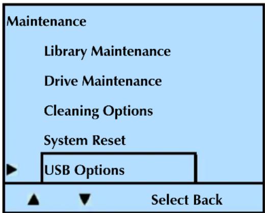
text_image
Maintenance Library Maintenance Drive Maintenance Cleaning Options System Reset USB Options Select Back-
Press Select.
-
Press ▲ or ▼ until the selection arrow (▶) points to New Library Code.
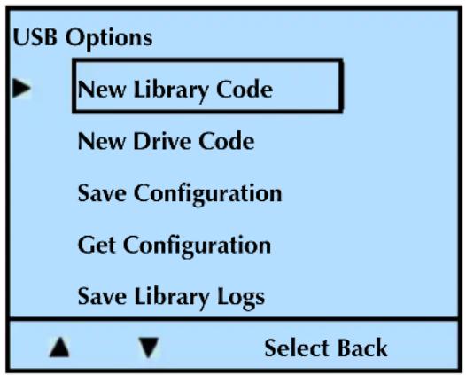
text_image
USB Options ► New Library Code New Drive Code Save Configuration Get Configuration Save Library Logs ▲ ▼ Select Back- Press Select.
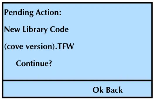
text_image
Pending Action: New Library Code (cove version).TFW Continue? Ok Back- Press OK to continue with the download, or Back to cancel the action.
- Press Back (as needed) to return to the Home screen.
SAVING LIBRARY LOGS
To save the diagnostic logs of the library:
- At the Home screen, press Maint.
If necessary, enter the operator panel password (see page 80).
- Press ▼ until the selection arrow (▶) points to USB Options.
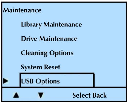
text_image
Maintenance Library Maintenance Drive Maintenance Cleaning Options System Reset USB Options Select Back-
Press Select.
-
Press ▲ or ▼ until the selection arrow (▶) points to Save Library Logs.
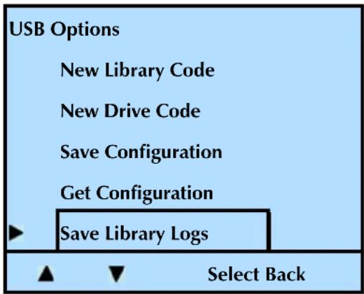
text_image
USB Options New Library Code New Drive Code Save Configuration Get Configuration Save Library Logs Select Back- Press Select.
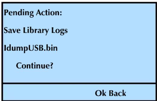
text_image
Pending Action: Save Library Logs IdumpUSB.bin Continue? Ok Back- Press OK to continue with the action, or Back to cancel the action.
Tandberg Data Technical Support can examine the log to determine the nature of the reported error (see www.tandbergdata.com).
- Press Back (as needed) to return to the Home screen.
LTOTOOL—TAPE DRIVE FIRMWARE UPGRADE
To upgrade firmware and create diagnostic listings for the LTO tape drive(s), download LTOTool. LTOTool allows you to upgrade firmware and perform diagnostics over the library's SCSI bus.
LTOTool is available as a free download at www.tandbergdata.com.
▶ Refer to the readme file provided with the program for installation instructions.
Refer to the program's online help for instructions on performing upgrades and diagnostics.
You can download new firmware at www.tandbergdata.com.

Caution
Do not upgrade firmware unless Tandberg Data Technical Support has advised you to do so. If performed improperly, the upgrade procedure can render your tape drive inoperable. Consult with Tandberg Data Technical Support before performing an upgrade.
USB PORT—TAPE DRIVE FIRMWARE UPGRADE
You can use the USB port to upgrade tape drive firmware. See “Connecting the Library to the USB Port” on page 21.
To download new code to the tape drive(s):
-
At the Home screen, press Maint.
If necessary, enter the operator panel password (see page 80). -
Press ▼ until the selection arrow (▶) points to USB Options.
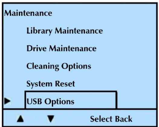
text_image
Maintenance Library Maintenance Drive Maintenance Cleaning Options System Reset USB Options Select Back-
Press Select.
-
Press ▲ or ▼ until the selection arrow (▶) points to New Drive Code.
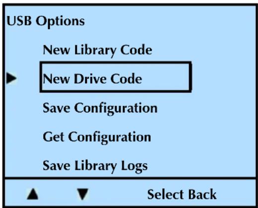
text_image
USB Options New Library Code New Drive Code Save Configuration Get Configuration Save Library Logs Select Back- Press Select.
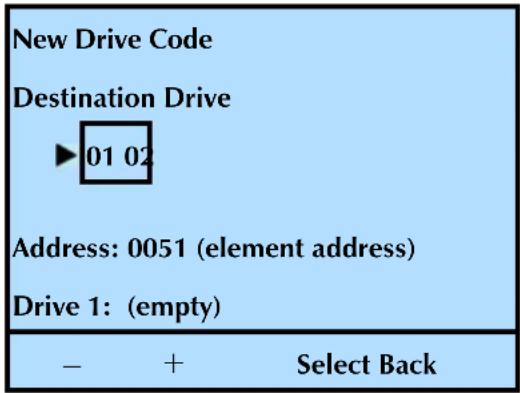
text_image
New Drive Code Destination Drive ►01 02 Address: 0051 (element address) Drive 1: (empty) - + Select Back- Press Select.
| Pending Action: New Drive Code IBM3FH.fmr Continue? |
| Ok Back |
- Press OK to continue with the download, or Back to cancel the action.
- Press Back (as needed) to return to the Home screen.
NOTES
8
TROUBLESHOOTING
This chapter describes problems that you might encounter while operating the library and provides suggestions for resolving the problems.
LIBRARY TROUBLESHOOTING
This section provides suggestions for solving problems that may occur when you are installing and operating the library.
LIBRARY INSTALLATION
If the library and backup software are not communicating after installation, check the following:
Power. Is the library's power cord inserted correctly, and is the power switch on?
√ SCSI connections. Make sure that the SCSI connections to the host computer and other devices on the bus are also secure.
√ Fibre Channel connections. Make sure that the Fibre Channel connections to the host computer and other devices on the bus are also secure.
√ Host adapter card installation. Make sure that you installed your host adapter card correctly. Refer to the documentation that came with your card for installation and troubleshooting instructions. Pay special attention to steps for setting various jumpers and switches on the card. Make sure that the card is properly seated.
√ SCSI controller type. Make sure that the SCSI controller is an LVD, non-RAID controller. Tandberg Data does not support the use of libraries or tape drives on RAID controllers.
√ SCSI IDs. Make sure that the SCSI IDs you selected for the tape drive or tape drives are not the same as the IDs used by any other devices on the SCSI bus, including the SCSI adapter card. Refer to page 52 for information about setting the SCSI IDs.
√ LVD SCSI devices. Because the tape drives installed in the library are LVD (low-voltage differential) devices, all other devices on the SCSI bus should also be LVD. These devices include the controller cards, terminators, and any other devices on the bus. For optimum performance, use an Ultra 160 SCSI host bus adapter.
Note: Although Ultra-2 and Ultra-3 LVD SCSI are compatible with single-ended SCSI, Tandberg Data does not support using the LVD library on a single-ended SCSI bus.
√ SCSI cable lengths. Make sure that the cabling for the SCSI bus attached to the tape drives does not exceed the maximum length restriction (see page 18).
√ Termination. Make sure that the SCSI bus is properly terminated as described on page 18. If another device previously terminated the SCSI bus and is no longer at the physical end of the bus, be sure to remove the terminator from that device.
! Important
Both LTO-2 and LTO-3 SCSI tape drives require Ultra 3 or LVD 160 terminator to function properly on the SCSI bus. An inadequate terminator will result in various SCSI bus issues, including bus hangs and Read/Write failures.
√ Tape Drive Cables. Ensure that the tape drive(s) are correctly cabled to the ADI Interface(s). See "Replacing a Tape Drive (same configuration)" on page 171.
√ Compatibility. Make sure that your library and tape drive(s) are compatible with the backup application you plan to use. Check www.tandbergdata.com for compatibility information.
√ Software installation. Make sure that your backup software is installed correctly (Refer to your software documentation.) Pay special attention to steps that describe how to configure the software for use with the library and tape drive(s).
√ Driver installation. Make sure that the driver for your controller card is installed. Refer to installation instructions for the controller card. Make sure that the appropriate drivers for the library and the tape drive(s) are installed. Refer to the installation instructions for your backup application regarding medium changer and tape drive drivers.
Notes:
Most versions of the product CD include Windows drivers for the library and tape drives. If your CD does not include drivers, you can download them from www.tandbergdata.com.
Only install these drivers if you are using the Windows native backup application or if your backup software instructs you to do so.
Driver installation may not be necessary and depends on the backup application that you use in your system. Refer to the installation instructions for your backup application for verification.
After checking the items above, reset the library as described on page 138.
LIBRARY OPERATION
If the library has been successfully operating in the past, but is now experiencing problems, check the following:
√ Control Mode. Make sure that the control mode is set correctly.
▶ Random mode (the default)—Only use this mode with an application that controls the library.
Sequential mode—Only use this mode if you plan to operate without a backup application. In Sequential mode, the library automatically processes cartridges in sequential order without direction from an application. See page 59 for information about setting Sequential mode.
√ Library functions. You can use the selections in the Maintenance menu to check specific library functions. See "Running a System Demo" on page 188 for instructions.
√ Error messages. Check the list of error messages in Appendix E, Error Messages for corrective actions.
√ Hardware operation. You can verify that the library hardware is operating using the following methods:
Use the Run System Demo mode under the library's Maintenance menu to move cartridges from random cells in and out of the tape drive(s). See page 188 for instructions.
Use the library's Move menu to import or export cartridges, and to move specific cartridges into and out of the tape drive(s). See page 120 for instructions.
Use LibTool to display the current inventory of cartridges, and to move cartridges in and out of the tape drive(s). Refer to the program's online help for instructions on performing upgrades. You can download LibTool from www.tandbergdata.com.
If the library reports an error during any of these tests, use the Remote Management Utility to obtain a diagnostic log from the library immediately after the error is reported (see "Logs" on page 114). Alternatively, you can use FTP (via the Ethernet port) to obtain a diagnostic log from the library (see page 190). Tandberg Data Technical Support can examine the log to determine the nature of the reported error.
√ Hardware Servo Error. If your library is reporting a hardware servo error, check the following:
Make sure the library is either installed in a rack or is resting on a hard, flat surface.
Make sure that there is nothing resting or pressing on the top of the library.
Make sure that the library is not oriented on its side.
Make sure that the library has the latest version of firmware installed. Firmware upgrade instructions begin on page 190.
If you are unable to resolve the problem, use the Remote Management Utility to obtain a diagnostic log from the library immediately after the error is reported (see "Logs" on page 114). Alternatively, you can use FTP (via the Ethernet port) to obtain a diagnostic log from the library (see page 190). Tandberg Data Technical Support can examine the log to determine the nature of the reported error.
√ Tape Drive Configuration. Ensure that the Drive Configuration (Drive/Drive Configuration) matches the tape drive(s) installed.
Note: ▶ If you have only one tape drive installed, the configuration must reflect one tape drive. The second, empty tape drive "slot" must indicate No Drive. See "Reconfiguring the Library and Resuming Operation" on page 178.
√ Firmware level. Make sure that your library and tape drive(s) contain the latest versions of firmware.
To check the library's code level, see page 141.
To check the tape drive's code level, see page 153.
To determine whether you have the latest versions, check the Tandberg Data web site at www.tandbergdata.com.
TAPE DRIVE TROUBLESHOOTING
Refer to the tape drive's Product Manual for detailed tape drive troubleshooting information. If you have been successfully operating the backup software and library in the past, but are now experiencing problems reading and writing data, check the following:
√ Write-protect switch. If you are writing data, make sure that the cartridge is write-enabled.
If the switch... the tape is...
does not cover the opening write-enabled
covers the opening write-protected
√ Cartridge type. Use the appropriate cartridges for your tape drive(s). See Table5-1 on page119 for information about selecting cartridges.
√ Cartridge age. If the cartridge has been in use for a long time or if it has been used frequently, try using a new cartridge.
√ Cleaning. Clean the tape drive(s) as described on page 132.
TAPE DRIVE FAILS WITH SPORADIC ERRORS
√ Terminator. Check the terminator used on the tape drive.
! Important
Both LTO-2 and LTO-3 SCSI tape drives require an Ultra 3 or LVD 160 terminator to function properly on the SCSI bus. An inadequate terminator will result in various SCSI bus issues, including bus hangs and Read/Write failures.
Both LTO-2 and LTO-3 SCSI tape drives are Ultra 160 SCSI devices and require a minimum Ultra 160 non-RAID SCSI card, Ultra 160 rated SCSI cabling, and an Ultra 3 Active SCSI terminator. Cabling and termination rated higher (Ultra 320, for example) is also acceptable.
An appropriate terminator is stamped with Ultra 3 or LVD 160 and “Active Negation.”
Your library was shipped with the appropriate terminator. If you incorporate the library into an existing setup that is not properly terminated, or if the original terminator is replaced during setup, you may experience the failures described below.
Failure symptoms include:
Read/Write failure
Bus hangs
Connectivity issues—tape drive not seen on bus or drops off bus
Command failures—commands to this device may fail while commands to other devices on the bus may work properly
BACKUP SOFTWARE REPORTS AN ERROR
Your backup software may report an error as a result of a failure to communicate with the tape drive(s) or library, a failure by a tape drive to write or read data, or because of a software configuration issue.
FAILURE TO COMMUNICATE WITH A TAPE DRIVE
Communication problems on the SCSI bus may be reported by the backup application as resets, a loss of communication with a tape drive, failure to detect a tape drive, I/O device errors, or parity errors. These types of errors may occur intermittently.
If you have a SCSI library, check the tape drive's installation on the SCSI bus, described in "Connecting to SCSI" on page 17.
If you have a Fibre Channel connection to your library (the tape drives installed in the library are Fibre Channel), check the Fibre Channel connection, described in "Connecting the Library to Fibre Channel" on page 20.
If you have an Ethernet connection to your library, check the library's Ethernet connection, described in "Connecting the Library to Ethernet" on page 21.
If the ADI interface is not connected properly, it is possible that the tape drive will not communicate on the SCSI bus (see "Replacing a Tape Drive (same configuration)" on page 171).
Use the Remote Management Utility (see "Logs" on page 114) and LTOTool (see page 196) to capture the diagnostic logs from the library and the tape drive(s) immediately after an error is reported by your backup software. See "Advanced Troubleshooting" on page 208 for information. Technical Support can examine the log to determine the nature of the reported error.
FAILURE BY A TAPE DRIVE TO WRITE OR READ DATA
If your backup software reports a media error, one of the following situations may have occurred:
The tape drive needs cleaning (see "Cleaning the Tape Drive" on page 132). Always try cleaning the tape drive before you assume the cartridge is bad. Be sure to use an LTO Cleaning Cartridge.
The cartridge needs to be replaced. Try using a different cartridge for the backup, making sure that the tape is not written in an unsupported format. Mark any cartridge that fails. If you notice that the same cartridge results in multiple failures, replace the cartridge.
The backup software has attempted to append data to a cartridge that previously failed. If a write media error previously occurred on the tape, the tape drive cannot append data at the point where the write media error occurred. You can attempt to overwrite the tape, but any attempt to append data will fail.
If you are trying to write data, the cartridge may be write-protected. Check the switch on the edge of the cartridge (see Figure 5-2 on page 119).
If the switch... the tape is...
does not cover the opening write-enabled
covers the opening write-protected
Use a pen or small screwdriver to move the switch. Do not use a pencil, because graphite may corrupt the tape.
If you used an application other than your normal backup software to write data to the tape, your backup software may report that it does not recognize the tape. For example, if you have used LTO Tool to write and read test data, the test tape will not be “recognized” by your backup software. Perform a tape erase using either LTOTool or your backup software.
BACKUP SOFTWARE CONFIGURATION ISSUES
If you suspect an issue with the backup software configuration, use LibTool and LTOTool to first confirm that the library and tape drive are working properly. Download and install LibTool and LTO tool from www.tandbergdata.com.

flowchart
graph LR
    A["WEB"] --> B["HOST"]
    B <--> C["LIBRARY"]
Use LibTool to:
▶ Detect the library
View the library's cartridge inventory
▶ Move tapes into and out of the tape drive
Use LTOTool to:
▶ Detect the tape drive
▶ Perform a Read/Write test
The readme file that accompanies the program (or the online help for the Windows version) provides instructions for using LibTool and LTOTool.
For any questions regarding software configuration, contact your software provider.
BEFORE CONTACTING TECHNICAL SUPPORT
Before contacting Tandberg Data Technical Support, complete the following steps to gather all of the required information. Having this information available before you call Technical Support will allow your representative to help you as efficiently as possible. When you have all of the required information, see “Contacting Tandberg Data Corporation” on page iii to contact Technical Support.
LIBRARY INFORMATION
Library serial number and firmware level. What is the library's serial number? What version of firmware is currently loaded in the library?
▶ Check www.tandbergdata.com for the latest release of StorageLibrary T24 firmware.
▶ Use the operator panel to display information about the library (see "Viewing Basic Library Information" on page 141).
If your library is not at the latest firmware level, use LibTool to update the firmware (see "LibTool—Library Firmware Upgrade" on page 193).
TAPE DRIVE INFORMATION
Tape drive serial number and firmware level. What is the tape drive's serial number? What version of firmware is currently loaded in the tape drive?
▶ Check www.tandbergdata.com for the latest release of LTO tape drive firmware.
Use the operator panel to display information about the tape drive(s). See "Viewing Basic Tape Drive Information" on page 153.
If your LTO tape drive is not at the latest firmware level, use LTOTool to update the firmware.
See "LTOTool—Tape Drive Firmware Upgrade" on page 196.
SCSI BUS INFORMATION (SCSI LIBRARY)
▶ SCSI host bus adapter make and model. What is the make and model of SCSI host bus adapter connected to the tape drives installed in the library? Make certain that the SCSI adapter is Ultra 160 SCSI and that any necessary drivers for the controller are installed.
Note: Tandberg Data does not support using the library on a RAID controller or on a single-ended controller.
▶ SCSI bus configuration. What is the configuration of the SCSI bus used by the library?
Are other SCSI devices attached to the SCSI bus?
What are the SCSI IDs of all devices attached to the same bus (both internal and external devices)?
Is the SCSI bus terminated at the physical end of the bus?
! Important
Both LTO-2 and LTO-3 SCSI tape drives require an Ultra 3 or LVD 160 terminator to function properly on the SCSI bus. An inadequate terminator will result in various SCSI bus issues, including bus hangs and Read/Write failures.
What is the total SCSI cable length for all devices (both internal and external devices) on the SCSI bus (see page 18 for length restrictions).
▶ Check all SCSI cable connectors for bent pins and confirm that all connectors are firmly seated.
▶ Operating system. What operating system are you using? Are all current patches installed?
Device drivers. Are the appropriate drivers installed for the SCSI host bus adapter? Refer to the installation instructions for your SCSI host bus adapter card.
BACKUP APPLICATION INFORMATION
▶ Backup application name and version. What backup application are you using?
- Compatibility. Does your application support the StorageLibrary T24? Refer to the supported hardware devices list from the application provider. See "Changing the Emulation Mode" on page 57 for information.
Device drivers. Are the appropriate drivers installed for the tape drive(s) and for the library?
Note: Driver installation may not be necessary and depends on the backup application that you use in your system. Refer to the installation instructions for your backup application for verification.
Driver installation information is available at: www.tandbergdata.com.
▶ Backup application log files. Have the log files from your backup application ready to send to Technical Support.
DIAGNOSTIC INFORMATION
▶ Library test results. Use LibTool to test moving tapes in and out of the tape drive, and then use the Remote Management Utility to capture a diagnostic log of the library (see "Logs" on page 114). Have the log file ready to send to technical support.
▶ Tape drive test results. Use LTOTool and run a Write/Read test of the tape drive(s) and then capture the diagnostic log from the tape drive(s) and save it to a file.
If the LTOTool Write/Read test reports an error, clean the tape drive(s) and run the test again on a new tape.
Have the diagnostic log file ready to send to Technical Support. Refer to the readme file or on line help available with the LTOTool for detailed instructions.
Diagnostic log taken after an error. Capture diagnostic logs from both the tape drive(s) and from the library immediately after your backup application reports an error.
▶ Use LTOTool to capture the diagnostic log from the tape drive(s).
Use the Remote Management Utility to capture a diagnostic log from the library (see "Logs" on page 114).
ADVANCED TROUBLESHOOTING
If you report a problem to Tandberg Data Technical Support, you may be asked to create a diagnostic listing. Use one of the following options for creating a diagnostic listing.
To create diagnostic listings for:
The Library—using the Remote Management Utility
▶ See Tools/ "Logs" on page 114.
The Tape Drive(s)—using LTOTool
LTOTool is available at www.tandbergdata.com.
See "LTOTool—Tape Drive Firmware Upgrade" on page 196 for instructions.
The Library using Ethernet—using the library's Remote Management Utility
See "FTP—Library Firmware Upgrade and Diagnostics" on page 190 for instructions.
To report a problem to Tandberg Data Technical Support, see page iii.
A
SPECIFICATIONS
This appendix provides the following information about the library:
| To view this information... go to... | |
| Storage capacity (this page) | |
| Size and weight page 210 | |
| Performance specifications page 210 | |
| Power specifications page 212 | |
| Environmental specifications page 213 | |
| Shipping specifications page 215 | |
| Universal serial bus page 215 | |
| Safety and regulatory agency compliance | page 215 |
STORAGE CAPACITY
The maximum storage capacity of the library depends on the type and number of cartridges installed, as shown in Table A-1.
Table A-1 Maximum library storage capacity
| Data Cartridge Type | Maximum Capacity per Cartridge^a | Maximum Library Capacity (24 Data Cartridges^a ) |
| LTO-2 (purple) | 400 GB | 9.6 TB |
| LTO-3 (slate blue) | 800 GB | 19.2 TB |
a Assuming a 2:1 compression ratio. Actual compressed capacity varies depending on the type of data being recorded and the system configuration
SIZE AND WEIGHT
TableA-2 lists the library's dimensions and weight.
Table A-2 Library dimensions and weight
| Dimensionsa(L x W x D) | 77.54 cm x 44.63 cm x 8.75 cm(29.0 x 17.57 x 3.45 inches) |
| Weight 20.9 kg (46.1 lb) with no cartridges installed b | |
^a Dimension from front rail mount to rear of chassis. Front bezel extends forward an additional 2.54 cm (1.5 inches).
b This weight includes the library with one full height tape drive, and two magazines.
PERFORMANCE SPECIFICATIONS
This section describes the following performance specifications for the library.
DATA TRANSFER RATE
The data transfer rate for the library depends on the model of tape drive(s) installed, as shown in TableA-3.
Table A-3 LTO Ultrium tape drive transfer rate and capacity
| Tape Drive | Maximum Data Transfer Rate | |
| Native Compressed | a | |
| LTO Ultrium 2 24 MB per second 173 GB per hour | ||
| LTO Ultrium 3 b | 60 MB per second 120 GB per hour | |
| LTO Ultrium 3 c | 80 MB per second 576 GB per hour | |
^a Assuming a 2:1 compression ratio. Actual compressed transfer rate varies depending on the type of data being recorded and the system configuration.
b When attached to an Ultra160 (Ultra3) SCSI bus. All sustained data rates are dependent on the capabilities of the SCSI bus (for example, an Ultra2 SCSI bus is limited to less than 40 MB/second). This data is for both the Hewlett Packard LTO-3 half height tape drive and the IBM LTO-3 half height tape drive.
c When attached to an Ultra160 (Ultra3) SCSI bus. All sustained data rates are dependent on the capabilities of the SCSI bus (for example, an Ultra2 SCSI bus is limited to less than 40 MB/second).
When installed in the library, a tape drive performs within its specifications. For more information about tape drive performance specifications, refer to the LTO Ultrium tape drive documentation available from the following web sites:
IBM — www.storage.ibm.com/tape/lto/oem/index.html
Hewlett Packard — www1.hp.com/storage/tapestorage.html
Each time the library is powered on, it performs a sequence of activities. During its power-on sequence, the library:
▶ Performs a power-on self-test (POST)
Runs self-diagnostics
Establishes communication with the tape drive(s)
Verifies the SCSI IDs
▶ Performs a cartridge inventory
The time required for the power-on sequence is measured from the time power is applied until the library indicates ready status.
The library's power-on sequence time is approximately:
360 seconds when the library contains 24 cartridges with bar code labels.
660 seconds when the library contains 24 cartridges without bar code labels.
CARTRIDGE INVENTORY
An application can issue a command to the library to check all cells for cartridges and scan bar code labels. After checking the cells, the library updates its cartridge inventory.
The average cartridge inventory time is approximately:
210 seconds when the library contains 24 cartridges with bar code labels.
660 seconds when the library contains 24 cartridges without bar code labels.
I/E PORT INVENTORY
Whenever a cartridge is inserted or removed through the I/E port, the library performs a cartridge inventory on the affected cell.
The average time for an individual cartridge cell inventory is:
15 seconds when the cartridge has a bar code label.
50 seconds when the cartridge does not have a bar code label.
MOVE COMPLETE TIME
Move complete time is the time it takes the library to remove a cartridge from a tape drive, return it to its cell, and load the new cartridge into the tape drive.
Move complete time is measured from the time the library receives the move command to the time the library returns status to the initiator indicating that the move is complete. The average move complete time is approximately 150 seconds. Worst case time to complete this command is 10 minutes.
RELIABILITY
The mean cycles between failures (MCBF) for the library is 250,000 cycles. This value does not include failures attributable to the tape drive or cartridges.
During one full cycle, the library completes the following actions:
Picks a cartridge from a tape drive
Places the cartridge in its cell
Picks a new cartridge from the cartridge cell
Loads the new cartridge into the tape drive
POWER SPECIFICATIONS
This sections describes the following power specifications for the library:
AC input voltages and power consumption
Power cord specifications
AC INPUT VOLTAGES AND POWER CONSUMPTION
The library includes an internal power supply that is capable of accepting 100 to 240 VAC at 50 or 60 Hz. The library has automatic AC input voltage selection. The library is capable of continuous operation when the AC power experiences intermittent operation, voltage surges, and voltage spikes. The maximum operating power consumption for the library is 65 Watts RMS.
POWER CORD SPECIFICATIONS
The library is shipped with two power cords: One for use in the US and Canada, and one for use in Europe.
US, Canada, and European Power Cord Specifications
Table A-4 Power Cord Specifications
| Power Cord | Description | Use | Connectors and Cordage | Certifications |
| US/Canada 2.3-meter (7.5-foot), three-conductor | 120-volt | One molded NEMA 5-15P male connectorOne molded IEC 320/EN60320 female connectorCordage is 18 AWG | UL Listed CSA Certified | |
| European 2.5-meter (8.2-foot) 230 to 250-volt | One CEE 7/7 male connectorOne IEC 320 C13 female connectorCordage is CENELEC HD-21 | VDE approved |
Requirements for International 220 VAC Power Cord
If you plan to use the library in a location other than the US/Canada or Europe, you must supply a power cord that meets the following specifications:
The power cord must have a grounded attachment plug of the proper type, rating, and safety approval for the intended country.
The power cord must have an IEC 320/EN60320 female connector on one end.
The cordage must be harmonized to CENELEC publication HD-21. The electrical characteristics and rating must be minimum H05VVF3G1.00 (10 A).
ENVIRONMENTAL SPECIFICATIONS
This section describes the following environmental specifications for the library.
GENERAL ENVIRONMENTAL SPECIFICATIONS
TableA-5 lists general environmental specifications for the library.
Table A-5 Environmental specifications
| Specification Operating | ^a | Storage^b or Non-Operating^c | Transportation^d |
| Ambient Temperature Range | +10°C to +40°C (+50°F to +104°F) | -40°C to +65°C (-40°F to +150°F) | -40°C to +65°C (-40°F to +150°F) |
| Temperature Variation ^f (Thermal Gradient) | 1°C per minute; max 10°C per hour (2°F per minute; max 18°F per hour) | 1°C per minute; max 20°C per hour (2°F per minute; max 36°F per hour) | 1°C per minute; max 20°C per hour (2°F per minute; max 36°F per hour) |
| Relative Humidity 20% to 80% Non-condensing | 10% to 90% Non-condensing | 10% to 90% Non-condensing | |
| Wet Bulb 26°C (79°F) | max 29°C (84°F) max 29°C | (84°F) max | |
| Altitude | -306 m to +3,048 m (-1,004 ft to +10,000 ft) | -306 m to +3,048 m (-1,004 ft to +10,000 ft) | -306 m to +12,192 m (-1,004 to +40,000 ft) |
a These measurements assume that the library is installed in accordance with the instructions in this manual.
b The library is in its original packaging. The packaging is designed to protect the library from condensation caused by extreme temperature variations (15°C or more). When the library is moved from a cold storage environment to a warm operating environment, it must be acclimated in its packaging for at least 12 hours before opening to prevent serious condensation damage from occurring.
c The library has been unpacked.
d The library has not been unpacked. The transportation period does not exceed 72 hours.
The upper ambient operating temperature limit of +40^ (+104^) is specified at +914.4m (+3,000 feet), derated linearly to +24^ (+75.2^) at +3,048m (+10,000 feet).
The data cartridges' temperature and humidity must be allowed to stabilize in the specified ambient environment for 24 hours.
PARTICULATE CONTAMINATION LIMITS
The ambient operating environment for the library should not exceed the particulate counts specified for the tape drive. For more information, refer to the LTO Ultrium tape drive documentation available from the following web sites:
IBM — www.storage.ibm.com/tape/lto/oem/index.html
Hewlett Packard — www1.hp.com/storage/tapestorage.html
ACOUSTIC NOISE LIMITS
The overall, averaged A-weighted sound pressure level (in decibels) for the library does not exceed the upper limits specified in Table A-6.
Table A-6 Acoustic noise limits
| Operating Mode dBA | a |
| The library is powered on and idle. 50 | |
| The robot is moving and the tape drive is operating in streaming mode. | 60^b |
^a dBA is the average A-weighted sound pressure level over the following frequency range: 5 Hz to 12.5 KHz.
b Represents a maximum sustained operational level.
SHOCK AND VIBRATION LIMITS
The library will operate normally after experiencing shock loads as specified in TableA-7. The operating shock levels indicate how much shock the library can withstand while the enclosed tape drive (or tape drives) is reading and writing data. The non-operating and storage shock levels indicate how much shock the library can withstand when it is not operating. After experiencing this amount of shock, the library will operate normally.
Table A-7 Shock limits
| Operating | Random vibration at 1 Hz to 400 Hz @ 0.3 Grms, 20 minutes per axisSwept Sine 5 Hz to 500 Hz to 5 Hz @ 0.3 g, 1 octave per minute, 3 sweeps per axis3 g, 5 ms half sine, 20 shocks each side |
| Non-Operating | Random vibration at 1 Hz to 400 Hz @ 1.06 Grms, 20 minutes per axis.Swept Sine 5 Hz to 500 Hz to 5 Hz @ 0.75 g, 1 octave per minute, 3 sweeps per axisTBD g, TBD ms half sine, 3 shocks per side, 18 total |
SHIPPING SPECIFICATIONS
The library's shipping carton passes the tests described in International Safe Transit Association (ISTA) Procedure 2A.
TableA-8 lists the weight and dimensions of the library packed for shipping. Packaging includes rack mounting kit, power cord, quick start guide, product manual, and product CD.
Table A-8 Shipping weight and dimensions
| Shipping Weight Dimensions (Length x Width x Depth) | |
| 27.7 kg(63.1 lb) | 91.3 x 57.15 x 28.19 cm(36 x 22.5 x 11.1 inches) |

Caution
If you need to re-pack and ship the library, refer to the packing instructions in Appendix D. To avoid damaging the library, use the original shipping carton and packing materials (or replacement packaging obtained from your vendor). The shipping carton and packing materials are not intended to be used for shipping items other than or in addition to the library and its accessories.
UNIVERSAL SERIAL BUS (USB) INTERFACE
The USB interface supports the following:
USB Mass Storage Devices (for example, Flash drives)
▶ FAT file formats (FAT, FAT12, FAT 16, and FAT 32)
Long file names
The USB interface does not support:
▶ Keyboards,
Pointer devices (computer "mouse")
Cameras
Multimedia devices
SAFETY AND REGULATORY AGENCY COMPLIANCE
The StorageLibrary T24 complies with the safety and regulatory agency standards listed below when installed in accordance with this manual.
UNDERWRITERS LABORATORY

The StorageLibrary T24 is listed by Underwriters Laboratories, Inc. Representative samples of this product have been evaluated by UL and meet the applicable U.S. and Canadian safety standards.
GS

The GS Mark for the StorageLibrary T24 demonstrates that it has met the requirements of EN60950-1:2001.
UNITED STATES: FCC DECLARATION OF CONFORMITY

We declare under our sole responsibility that:
Product Name: StorageLibrary T24
To which this declaration relates, is in conformity with the following standard(s) or other normative documents:
ANSI C63.4-1992 Methods of Measurement
Federal Communications Commission 47 CFR Part 15, Subpart B
15.107 (b) Class A Conducted Limits
15.109 (b) Class A Radiated Emission Limits
This device complies with Part 15 of the FCC Rules. Operation is subject to the following two conditions: (1) This device may not cause harmful interference, and (2) This device must accept any interference received, including interference that may cause undesired operation.
This equipment has been tested and found to comply with the limits for a Class A digital device, pursuant to Part 15 of the FCC Rules. These limits are designed to provide reasonable protection against harmful interference when the equipment is operated in a commercial environment. This equipment generates, uses, and can radiate radio frequency energy and, if not installed and used in accordance with this manual, may cause harmful interference to radio communications. Operation of this equipment in a residential area is likely to cause harmful interference in which case the user will be required to correct the interference at his own expense.
Shielded cables are required for this device to comply with FCC Rules. Use shielded cables when connecting this device to others.
CANADIAN VERIFICATION

This Information Technology Equipment has been tested and found to comply with the following European directives:
(1) EMC Directive 89/336/EEC, amended by directive 93/68/EEC, according to:
EN55022 (Class A)
EN55024
EN 61000-3-2
EN 61000-3-3
(2) Low Voltage Directive 73/23/EEC, amended by directive 93/68/EEC, according to: IEC 60950-1
JAPAN
Translation: This is a Class A product based on the standard of the Voluntary Control Council for Interference by Information Technology Equipment (VCCI). If this equipment is used in a domestic environment, radio disturbance may arise. When such trouble occurs, the user may be required to take corrective actions.
AUSTRALIA AND NEW ZEALAND
This device has been tested and found to comply with the limits for a Class A digital device, pursuant to the Australian/New Zealand standard AS/NZS 3548 set out by the Australian Communications Agency.
RESTRICTION OF HAZARDOUS SUBSTANCES IN ELECTRICAL AND ELECTRONIC EQUIPMENT (ROHS)
The RoHS marking indicates that the StorageLibrary T24 is in compliance with European Council Directive 2002/95/EC, on the restriction of the use of certain hazardous substances in electrical and electronic equipment.
WASTE OF ELECTRONIC AND ELECTRICAL EQUIPMENT (WEEE)
This device is in compliance with 2002\96\EC Waste of Electronic and Electrical Equipment (WEEE).
NOTES
B
INTERFACE SPECIFICATION
This appendix provides information about the interface options of the library and the tape drives.
| To view this information... go to... | |
| SCSI Interface Specifications—SCSI tape drive only (this page) | |
| Fibre Channel Interface Specifications—FC tape drive only | page 226 |
| Ethernet Specifications—Library page 227 |
The StorageLibrary T24 has a standard SCSI interface through the tape drives, via the Automation/Drive Interface - Command (ADC), which support the commands in this section.
Note: The library communicates with the host through the SCSI interface of the tape drive(s) via the ADI serial interface. The SCSI interface as seen by the host is the SCSI interface of the tape drive. The library is shown as LUN 1 of the tape drive's SCSI ID.
For information about how LTO Ultrium tape drive's support SCSI communications, refer to the tape drive documentation, available from:
IBM — www.storage.ibm.com/tape/lto/oem/index.html
Hewlett Packard — www1.hp.com/storage/tapestorage.html
For information about ADI, see: Automation/Drive Interface - Command (ADC)
▶ T-10 — www.t10.org
SCSI INTERFACE SPECIFICATIONS
The StorageLibrary T24 has a standard SCSI interface through the tape drives, via the Automation/Drive Interface - Command (ADC), which support the commands in this section.
Note: The library communicates with the host through the SCSI interface of the tape drive(s) via the ADI serial interface. The SCSI interface as seen by the host is the SCSI interface of the tape drive. The library is shown as LUN 1 of the tape drive's SCSI ID.
This section provides requirements and specifications for the SCSI interface, including information about the following:
▶ SCSI cable and terminator requirements
▶ SCSI communications
Elements and element addresses
For information about how LTO Ultrium tape drive's support SCSI communications, refer to the tape drive documentation, available from:
IBM — www.storage.ibm.com/tape/lto/oem/index.html
Hewlett Packard — www1.hp.com/storage/tapestorage.html
For information about ADI, see: Automation/Drive Interface - Command (ADC)
SCSI CABLE REQUIREMENTS
SCSI cables and terminators are included with the library. The wide LVD SCSI cable conforms to SCSI-3 specifications. Check the tape drive documentation for information about SCSI cable requirements.
If you want to use your own SCSI cable(s), follow these guidelines:
Use high-density, wide (68-pin) Ultra 160 SCSI cables that conform to SCSI-3 specifications. To comply with the regulations and standards listed in Appendix A, all SCSI cables used with the library must be properly shielded.

Caution
Although the tape drive's wide LVD SCSI interface is compatible with single-ended SCSI, Tandberg Data does not support the use of the tape drives in this library on a single-ended bus or on a bus with single-ended devices attached.
All wide SCSI configurations (single-ended, LVD, and HVD) use the same 68-pin connector. Attaching the tape drive's directly to an HVD SCSI bus may cause the SCSI bus to hang.
SCSI TERMINATOR REQUIREMENTS
One wide Ultra 3 Active SCSI terminator is provided with the library. If you want to use your own terminator, use a high-quality Ultra 3-rated Active SCSI terminator. An appropriate terminator is stamped with Ultra 3 or LVD 160 and "Active Negation."
! Important
Both LTO-2 and LTO-3 SCSI tape drives require an Ultra 3 or LVD 160 terminator to function properly on the SCSI bus. An inadequate terminator will result in various SCSI bus issues, including bus hangs and Read/Write failures.
SCSI COMMUNICATIONS
This section provides information about how the library communicates on the SCSI bus via the tape drives. As described in this section, a SCSI application program communicates with the library through the tape drive(s) via ADI to perform the following actions:
Move cartridges between the storage locations and a tape drive
Update and access information stored in the cartridge inventory
▶ Set various operating parameters
▶ Inquire about the status of a specific operation
▶ Scan bar code labels
▶ Prevent the library door from being opened
▶ Prevent the use of certain operator panel menus
Inquire about the library serial number
▶ Perform diagnostics and receive results
▶ Upload diagnostic data
▶ Upgrade the library firmware
For more information about SCSI communications, refer to:
The tape drive's Product Manual
The Automation/Drive Interface - Command (ADC)
SCSI Commands
The initiator sends commands to the library through a tape drive via ADI to request an operation. Table B-1 lists and briefly describes the SCSI commands supported by the library.
Note: For information about tape drive commands, refer to the tape drive documentation.
Table B-1 SCSI command set supported by the library
| When you issue this command ... | OP Code | The library does this ... |
| INITIALIZE ELEMENT STATUS(6 bytes) | 07h | Checks all element addresses for cartridges and scans bar code labels.Typical time to complete: 12 seconds/single cell, 150 seconds/24 cells.Worst case time to complete: 3 hours |
| INITIALIZE ELEMENT STATUS WITH RANGE(10 bytes) | 37h | Checks a range of elements or all the storage elements for cartridges.Also scans bar code labels.Typical time to complete: 12 seconds/single cell, 150 seconds/24 cells.Worst case time to complete: 3 hours |
| INQUIRY(6 bytes) | 12h | Sends information about its parameters, including the library serial number, to the initiator. |
| LOG SELECT(10 bytes) | 4Ch | Manages statistical information maintained by the library. |
| LOG SENSE(10 bytes) | 4Dh | Returns statistical and condition information to the initiator. |
| MODE SELECT(6 bytes) | 15h | Accepts specific element addresses, LCD information, and operating parameters from the initiator. Can also prevent access to selected operator panel menus. |
| MODE SENSE(6 bytes) | 1Ah | Reports its operating mode parameters to the initiator. |
| MOVE MEDIUM(12 bytes) | A5h | Moves a cartridge from one location to another.Typical time to complete: 70 secondsWorst case time to complete: 10 minutes |
| POSITION TO ELEMENT(10 bytes) | 2Bh | Positions the cartridge loader at a specific location (element address).Typical time to complete: 10 secondsWorst case time to complete: 5 minutes |
| PREVENT/ALLOW MEDIUM REMOVAL(6 bytes) | 1Eh | Disables or enables the interlock mechanism in the I/E port, preventing or allowing the user from accessing cartridges through the I/E port. |
| READ ELEMENT STATUS(12 bytes) | B8h | Reports the status of its medium transport, storage, import/export, and data transfer elements to the initiator. |
| RECEIVE DIAGNOSTIC RESULTS(6 bytes) | 1Ch | Returns diagnostic results from the last SEND DIAGNOSTIC command. |
| RELEASE(6 bytes or 10 bytes) | 17h57h | Releases a unit reservation previously set by the initiator using the RESERVE command. |
| REQUEST SENSE(6 bytes) | 03h | Returns sense data to the initiator. |
| REQUEST VOLUME ELEMENT ADDRESS(12 bytes) | B5h | Returns the element descriptors (including element address and status flags for each element) created as a result of the SEND VOLUME TAG command. Data is returned in element address order. |
| RESERVE(6 bytes or 10 bytes) | 16h56h | Reserves the library. |
| REZERO UNIT(6 bytes) | 01h | Implemented to provide software compatibility when it is required.Because the library does not need to calibrate its mechanics, it always returns and immediate Good status in response to this command. |
| SEND DIAGNOSTIC(6 bytes) | 1Dh | Requests that a self test or another specific test be performed. |
| SEND VOLUME TAG(12 bytes) | B6h | Compares the template it receives from the initiator to the cartridge inventory information in memory, and determines which bar code labels match the template. |
| TEST UNIT READY(6 bytes) | 00h Informs the initiator whether it is ready to accept all other commands. | |
| WRITE BUFFER(10 bytes) | 3Bh Writes new microcode received from the initiator into its flash EEPROM. The new microcode must be sent in sections through multiple WRITE BUFFER commands. | |
Status bytes
After the library executes a command, it issues a status byte to the initiator that indicates whether it performed the command successfully. Table B-2 describes the four status bytes supported by the library.
Table B-2 Status byte descriptions
| Status Byte Hex | Value | Description |
| Good 00h Indicates that the library successfully completed the operation. | ||
| Check Condition | 02h | Indicates that an error, exception, or abnormal condition has caused sense information to be set. The initiator can issue a REQUEST SENSE command to access this information. |
| Busy | 08h Indicates that the library is unable to accept a command from the initiator. | |
| Reservation Conflict | 18h Indicates that the elements identified in the command are reserved by another initiator. | |
Sense Keys
When the library returns Check Condition status to the initiator, the initiator can issue a REQUEST SENSE (03h) command to receive information about the error, exception, or abnormal condition. This information includes a sense key, which describes the general error or change of state. Table B-3 describes the sense keys supported by the library.
Table B-3 Supported sense keys
| Sense Key | Hex Value | Description |
| No Sense | 0h | Indicates that there is no specific sense key information to be reported. |
| Not Ready | 2h | Indicates that the library cannot accept any motion commands. |
| Hardware Error | 4h | Indicates that the library detected a hardware failure. |
| Illegal Request | 5h | Indicates that there was an illegal parameter in the command descriptor block (CDB) or in the additional parameters supplied as data for some command. |
| Sense Key Hex | Value | Description |
| Unit Attention 6h Indicates that the state of the library may have changed. | ||
| Aborted Command Bh Indicates that the library aborted the last command. | ||
ELEMENTS AND ELEMENT ADDRESSES
Elements are the locations in the library that can accept a cartridge.
| Element Description | |
| Medium transport | The cartridge handling mechanism (robot) is the medium transport element. This mechanism moves the cartridges between the tape drive(s) and the storage cells. |
| Storage (slots)a | The library has 24 storage elements. |
| Data transfer A tape drive is a data transfer element that reads and writes data as requested by the host. | |
| Import/Exporta | The library has one I/E port to load cartridges individually into the library. |
^a The storage slots/cells increase or decrease based on the I/E Port setting (enabled or disabled). Disabling the I/E Port increases the storage slot/cell count. You can also assign slot/cell 2 as a “fixed” cleaning slot (see “Setting Up Automatic Tape Drive Cleaning” on page 63).
The library maintains current information about each element in its cartridge inventory, which is stored in memory.
Element Addresses
Each of the elements in the library requires an address so it can be identified by SCSI commands. Figure B-1 and Figure B-2 shows the default addresses assigned to each element in the library.
Note: The default element addresses are identical to the element indexes. The library uses element indexes to identify the library elements when performing diagnostic operations from the operator panel.
Use the MODE SELECT command to change the address of each element in the library.
I/E Port enabled/No fixed cleaning slot—The following figure shows the element addresses for this configuration.
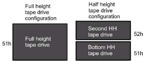
text_image
Full height tape drive configuration Half height tape drive configuration 51h Full height tape drive Second HH tape drive 52h Bottom HH tape drive 51h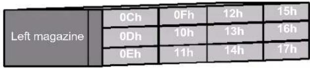
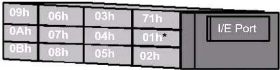
text_image
09h 06h 03h 71h 0Ah 07h 04h 01h* 0Bh 08h 05h 02h I/E PortFigure B-1 Element addresses (I/E port enabled/no fixed cleaning slot)
Note: If the fixed cleaning slot is enabled, this cell becomes the fixed cleaning slot (labeled 01* in Figure B-1) and all storage element numbers reduce by one. The fixed cleaning slot will not be accessible through SCSI.
I/E Port disabled/No fixed cleaning slot—The following figure shows the element addresses for this configuration.
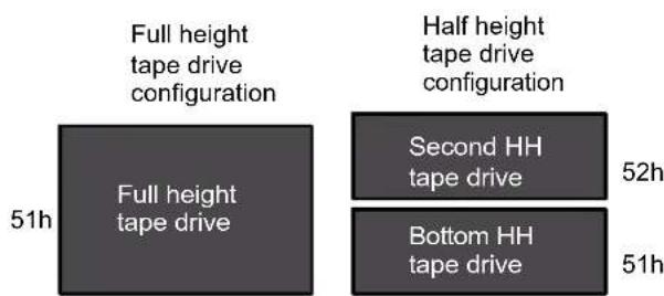
text_image
Full height tape drive configuration Half height tape drive configuration 51h Full height tape drive Second HH tape drive 52h Bottom HH tape drive 51h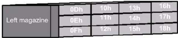
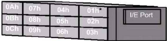
text_image
0Ah 07h 04h 01h 0Bh 08h 05h 02h 0Ch 09h 06h 03h I/E PortFigure B-2 Element addresses (I/E port disabled/no fixed cleaning slot)
Note: If the fixed cleaning slot is enabled, this cell becomes the fixed cleaning slot (labeled 01* in Figure B-2) and all storage element numbers reduce by one. The fixed cleaning slot will not be accessible through SCSI.
FIBRE CHANNEL INTERFACE SPECIFICATIONS (FC TAPE DRIVE)
Fibre Channel cables are not included with the library. The number of optical fiber cables required for attaching the library to a Fibre Channel network depends on how many tape drives are installed.
Each of the tape drive optical fiber ports contains a transmitter and receiver optical subassembly. The transmitter subassembly contains an internal semiconductor laser diode that operates at a wavelength of 850 nm (nanometers).
Use either 50-micron or 62.5-micron multi-mode optical fiber cables with dual single-channel (LC) connectors.
50-micron multi-mode optical fiber cables must comply with the 400-M5-SN-I classification as specified in the Fibre Channel standard (FC-PI-2).
62.5-micron multi-mode optical fiber cables must meet the 400-M6-SN-I classification.
Table B-4 Multi-mode optical cable characteristics
| Cable type Transmitter Data Rate | (MB/sec.) | Maximum Distance |
| 50-micron multi-mode fiber^a | 850 nm shortwave laser | 400 .5 m – 150 m |
| 62.5-micron multi-mode fiber^b | 850 nm shortwave laser | 400 .5 m – 70 m |
a Complies with the 400-M5-SN-I classification
b Complies with the 400-M6-SN-I classification
ETHERNET SPECIFICATIONS
This section provides specifications for the library's Ethernet interface, including information about the following:
▶ General Ethernet information
▶ Cable requirements
▶ Ethernet port pin assignments
GENERAL ETHERNET INFORMATION
The Ethernet port allows connection to a 10/100Base T Ethernet network. You can use the Ethernet connection to perform the following activities:
▶ Monitor library operations using the built-in Remote Management utility (see Chapter 4)
▶ Upload diagnostic information from the library and tape drives using FTP (see "Creating a Diagnostic Listing via FTP" on page 192)
Upgrade the library's firmware using FTP (see "Upgrading Library Firmware via FTP" on page 192)
ETHERNET CABLE REQUIREMENTS
The Ethernet port connector is a pin-through-hole RJ-45 shielded connector. To connect to the Ethernet port, use the shielded Category 5 (10/100BaseT connection) data-grade cable included with the library or a similar Category 5 cable that is compliant with EIA/TIA 568.
ETHERNET PORT PIN ASSIGNMENTS
TableB-5 shows the Ethernet port's pin assignments and functions.
Table B-5 Ethernet port pin assignments and functions
| Pin number Function | ||||
| 1 | TD+ | |||
| 2 | TD- | |||
| 3 | RD+ | |||
| 4 | N | o | t us | ed |
| 5 | N | ot | us | ed |
| 6 | R | D- | ||
| 7 | N | ot | us | ed |
| 8 | N | ot | us | ed |
Notes
C
WRITE ONCE, READ MANY (WORM) CAPABILITY
OVERVIEW
Certain records retention and data security applications require a Write Once, Read Many (WORM) method for storing data on tape. To meet this data storage requirement, a new WORM feature is now available on the StorageLibrary T24 when you have an LTO-3 tape drive installed.
Note: Only the LTO-3 tape drive has WORM capability. It is not available on the LTO -2 or LTO -1 tape drives.
No physical hardware changes are required to make the tape drive compatible with the WORM feature; however, appropriate WORM-capable drive firmware must be installed. See "Requirements" on page 231 to determine the firmware requirements.
WORM MEDIA
Because standard read/write media are incompatible with the WORM feature, a specially formatted WORM tape cartridge (see Figure C-1) is required. Each WORM cartridge has a unique, worldwide cartridge identifier (WWCID), which comprises the unique CM chip serial number and the unique tape media serial number.
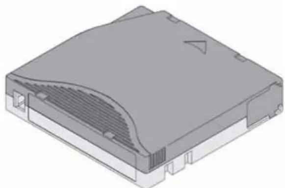
natural_image
3D rendering of a gray electronic device casing with ventilation slots and mounting holes (no text or symbols visible)Figure C-1 Ultrium 3 WORM tape cartridge
TableC-1 lists WORM media specifications.
Table C-1 WORM tape cartridge specifications
| Tape Cartridge Case Color Native Data Capacity | |
| Ultrium 3 WORM Two toned colored cartridge ^a | 400 GB (800 GB at 2:1 compression) |
a The two-toned coloring allows you to easily distinguish WORM cartridges from Write/Read cartridges.
DATA SECURITY ON WORM MEDIA
Certain built-in security measures help ensure that the data written on a WORM cartridge does not become compromised, for example:
The format of an IBM Ultrium 3 400 GB WORM Tape Cartridge is unlike that of standard read/write media. This unique format prevents a drive that lacks WORM-capable firmware from writing on a WORM tape cartridge.
When the LTO-3 tape drive senses a WORM cartridge, the firmware prohibits the changing or altering of user data already written on the tape. The firmware keeps track of the last appendable point on the tape.
WORM MEDIA ERRORS
The following conditions cause WORM media errors to occur:
Information in the servo manufacturer's word (SMW) on the tape must match information from the cartridge memory (CM) module in the cartridge.
If it does not match, the tape drive will report a Media Error code.
If your backup application or operating system returns SCSI sense information, the Sense information will be Sense Key (03) Medium error.
Inserting a WORM tape cartridge into a tape drive that is not compatible with WORM causes the cartridge to be treated as an unsupported medium. The tape drive will report a media Error Code 7.
Only LTO-3 tape drives have WORM capability. Inserting a WORM cartridge into an LTO-2 or an LTO-1 tape drive will produce the above error.
If you are using an LTO-3 tape drive and receive the above error, upgrading your LTO-3 tape drive's firmware to the correct code level will resolve the problem. The firmware must be at version 54xx or higher and is available at www.tandbergdata.com.
REQUIREMENTS
The WORM feature requires the following:
LTO-3 generation of tape drive—the WORM feature is not available on earlier generations of LTO tape drives (LTO-2 or LTO-1)
WORM-capable drive firmware release 54xx or higher
▶ Special WORM tape cartridges
You can use LTOTool to determine the firmware level currently in your tape drive(s). Refer to the readme file provided with the program for installation instructions. Refer to the program's online help for instructions on determining the tape drive(s) firmware level.
If your tape drive has an earlier version of firmware, you can download the updated firmware by visiting the download page on the Tandberg Data web site at www.tandbergdata.com.
Note: Refer to "FTP—Library Firmware Upgrade and Diagnostics" on page 190 for instructions on upgrading tape drive firmware.
TAPEALERT FLAGS
TableC-2 shows the new TapeAlert flags associated with the WORM cartridge.
Table C-2 TapeAlert flags associated with the WORM media
| Parameter Code Description | Set Clear Type | |||
| In Hex | In Decimal | |||
| 3Bh | 59 | (WORM Medium – Integrity Check Failed) Set when the tape drive determines that the data on tape is suspect from a WORM point of view. | L Critical | |
| 3Ch | 60 | (WORM Medium – Overwrite Attempted) Set when the tape drive rejects a Write operation because the rules for allowing WORM writes have not been met. | E | |
ERROR CODES
Tape drive errors associated with the new WORM capability result in either a Medium Error (Sense Key 3h) or a Data Protect error (Sense Key 7h). The tape drive returns this error information in response to a SCSI REQUEST SENSE command. Refer to the tape drive SCSI reference for additional information about the error codes returned by the REQUEST SENSE command.
TableC-3 shows the new ASC/ASCQ error codes for Sense Key 3h (Medium Error).
Table C-3 ASC/ASCQ error codes for a Medium Error (SK 3) with WORM media
| ASC ASCQ Description | ||
| 04h 10h Logical Unit Not Ready, Auxiliary Memory Not Accessible. | ||
| 11h 12h Auxiliary Memory Read Error | ||
| 30h | 0Dh | Medium Error/WORM Medium – Integrity Check: Set when the tape drive rejects a Read operation because the current cartridge is a Suspicious WORM cartridge, and the WTRE bit is set to 0. |
TableC-4 shows the new ASC/ASCQ error codes for Sense Key 7h (Data Protect).
Table C-4 ASC/ASCQ error codes for a Data Protect error (SK 7) with WORM media
| ASC ASCQ Description | ||
| 30h | 0Dh | Data Protect/WORM Medium – Integrity Check: Set when the tape drive rejects a Write operation because the current cartridge is a Suspicious WORM cartridge. |
| 30h | 0Ch | Data Protect/WORM Medium – Overwrite Attempted: Set when the tape drive rejects a Write operation because the rules for allowing WORM writes have not been met. |
D
SHIPPING THE LIBRARY
This chapter describes the process of returning the library for service. If you need to return the library for service, first contact your service provider. If your service provider instructs you to return the library directly to Tandberg Data, contact Tandberg Data Technical Support (see page iii) to obtain a Return Materials Authorization (RMA) number and the shipping address. When you have the RMA number, follow these instructions.
PREPARING THE LIBRARY FOR SHIPPING

Caution
You must park the robot prior to moving or shipping the library to avoid damaging the internal components and voiding your warranty.
To prepare the library for shipping:
- Remove all of the cartridges from the library. (See page 126 for instructions.) Make sure that the tape drive(s) contain no cartridges.
- Park the library by following these steps:
a. At the Home screen, press Maint. If necessary, enter the operator panel password (see page 80).
b. Press ▼ until the selection arrow (▶) points to Library Maintenance, and then press Select.
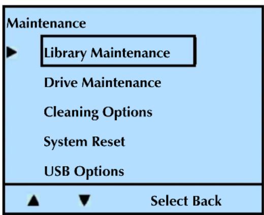
text_image
Maintenance ► Library Maintenance Drive Maintenance Cleaning Options System Reset USB Options ▲ ▼ Select Backc. Press ▼ until the selection arrow (▶) points to Park For Shipping.
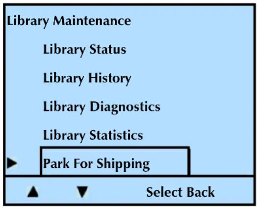
text_image
Library Maintenance Library Status Library History Library Diagnostics Library Statistics Park For Shipping Select Backd. Press Select.
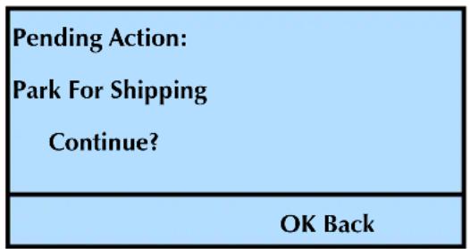
text_image
Pending Action: Park For Shipping Continue? OK Backe. Press OK to complete the process. When the robot is parked, the following screen appears
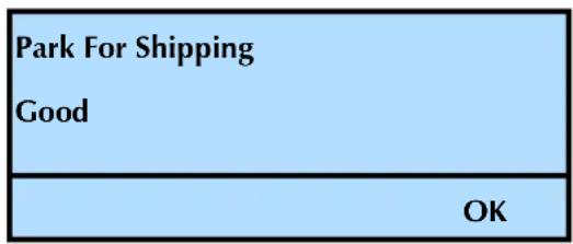
text_image
Park For Shipping Good OKREPLACING THE SHIPPING LOCK
Follow these steps to replace the shipping lock. Your library shipped with one of these three shipping locks. Follow the instructions appropriate for the lock that originally shipped with the library.
Plastic shipping lock Three-prong shipping lockStandard shipping lock
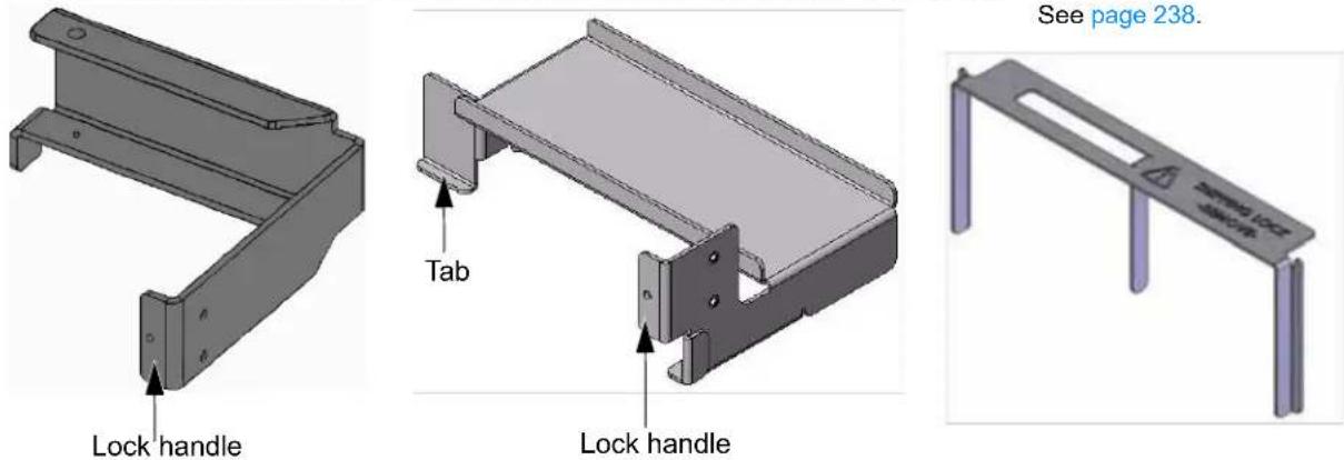
text_image
See page 238. Lock handle Tab Lock handleFigure D-1 Shipping locks
PLASTIC OR STANDARD SHIPPING LOCK INSTALLATION

Caution
This step must be completed after you "park the robot" described in the previous section. You can damage the robot if it is not fully parked prior to installing the lock. See "Preparing the Library for Shipping" on page 233.
- Remove the left magazine. Press the left magazine eject button. While supporting it, gently slide the magazine straight out of the library.

Caution
Use care not to twist the magazine or move it side to side as you insert or remove it from the library. Not inserting it straight into / pulling it straight out of the opening can damage components inside the library.
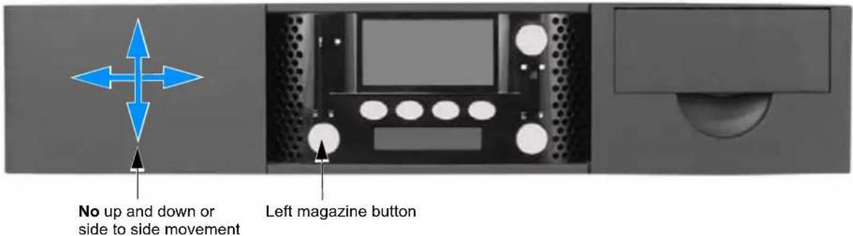
text_image
No up and down or side to side movement Left magazine buttonFigure D-2 Shipping lock replacement-step 1
- Power the library off. Press the 0 on the back panel.
- Insert the shipping lock. Follow the instructions in the appropriate section below for your shipping lock.
Plastic Shipping Lock (shown as red in the two illustrations)—Carefully follow steps a, and b to properly install the shipping lock.
a. Gently slide the shipping lock into place. This illustration shows the proper location and orientation.
Top View—top cover removed for clarity
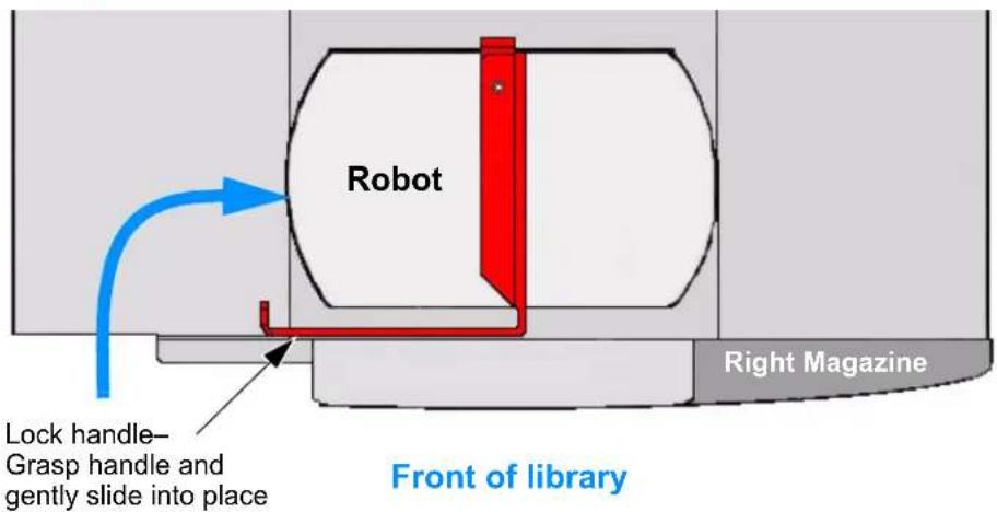
text_image
Robot Lock handle- Grasp handle and gently slide into place Right Magazine Front of libraryFigure D-3 Shipping lock replacement—plastic shipping lock step 1
! Important
This shows the library with the top cover removed for clarity. DO NOT remove the top cover or you will void your warranty.
b. Secure the lock with the screw as shown here.
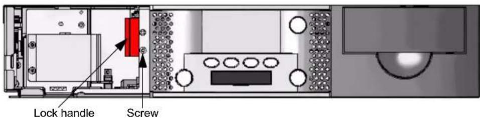
text_image
Lock handle ScrewFigure D-4 Shipping lock replacement–plastic shipping lock step 2
Standard Shipping Lock—Carefully follow steps a, b, and c to properly install the shipping lock.
! Important
These views show the library with the top cover removed for clarity. DO NOT remove the top cover or you will void your warranty.
a. Gently slide the shipping lock into place.
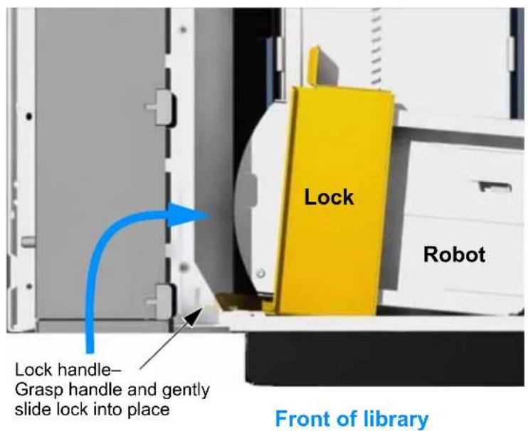
text_image
Lock Robot Lock handle- Grasp handle and gently slide lock into place Front of libraryFigure D-5 Shipping lock replacement-standard shipping lock step 1
b. Grasp the lock handle and gently rotate the robot toward the front of the library to lock the "tab" under the rail as shown here.
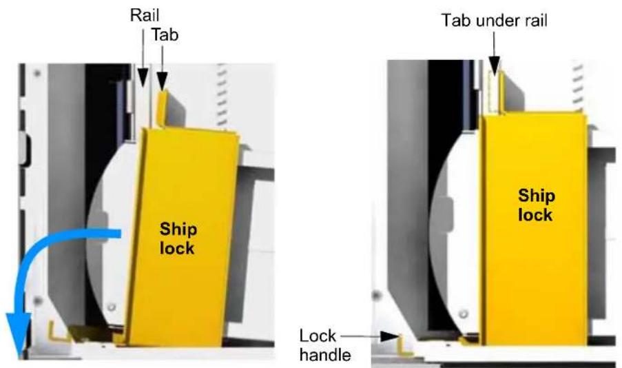
text_image
Rail Tab Ship lock Tab under rail Ship lock Lock handleFigure D-6 Shipping lock replacement-standard shipping lock step 2
c.Secure the lock with the screw as shown here.
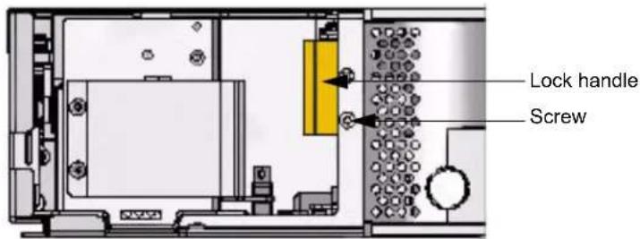
text_image
Lock handle ScrewFigure D-7 Shipping lock replacement-standard shipping lock step 3
- Replace the magazine. While supporting it, gently slide the left magazine straight into the library. When you encounter resistance, press the magazine firmly and it "snaps" into place. Continue with "Accessories" on page 239.

Caution
Use care not to twist the magazine or move it side to side as you insert or remove it from the library. Not inserting it straight into / pulling it straight out of the opening can damage components inside the library.
THREE-PRONG SHIPPING LOCK INSTALLATION

Caution
This step must be completed after you "park the robot" described in the previous section. You can damage the robot if it is not fully parked prior to installing the lock. See "Preparing the Library for Shipping" on page 233.
Follow these steps to remove the three-prong shipping lock.
- Power the library off. Press the 0 on the back panel.
- Access the top of the library. If the library is installed in a rack and you do not have access to the top, remove the library from the rack before proceeding (see "Removing the Library from the Rack" on page 239).
- Insert the lock. Gently slide the lock straight down into the openings in the top cover as shown here.

text_image
Lock OpeningsFigure D-8 Shipping lock replacement—three prong shipping lock
- Secure the lock. Place tape on both ends of the lock to secure it in place.
ACCESSORIES
After installing the shipping lock (any version), remove the following from the library and tape drives:
Power cord
Ethernet cable
▶ SCSI cables or Fibre Channel cables
▶ SCSI terminator
REMOVING THE LIBRARY FROM THE RACK
| Warning | The library weighs 43 pounds (19.5 kg). Two people are needed to move or lift the library. Most of the weight is toward the back of the library. |
| Warnung | Die Library wiegt 19.5 kg. Es sind mindestens 2 Personen erforderlich, um die Library zu bewegen oder zu heben. Der hintere Teil Library hat das Größte Gewicht. |
| Advertencia | La biblioteca montada sobre bastidor pesa 19.5 kg. Se necesitan dos personas para mover o levantar la biblioteca. La parte trasera de la biblioteca es la de mayor peso. |
If the library is installed in a rack, remove it as described below.
! Important Do not ship the rack-mounting hardware if you are returning the library for service.
- From the back of the rack, use a #2 Phillips screwdriver to remove the two screws that secure the library to the rails (see Figure D-9). Save the screws.
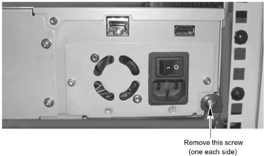
text_image
Remove this screw (one each side)Figure D-9 Removing the screws securing the library to the rails
- From the front of the rack, slide the library forward and out of the rack (see Figure D-10).
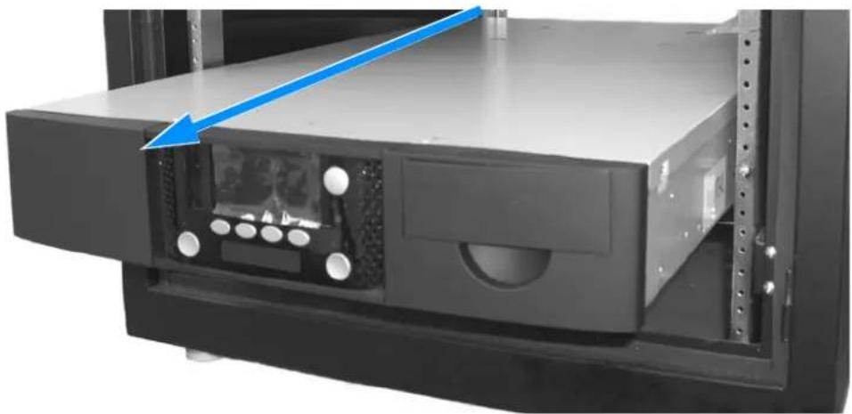
natural_image
Close-up of a server rack unit with a blue arrow pointing to the front panel (no visible text or symbols)Figure D-10Removing the library from the rack
PACKING THE LIBRARY
Use the original packing materials (shipping box, foam cushions, foam spacers, and antistatic bag) to pack the library. You will also need packing tape.

Caution
To avoid damaging the library and voiding your warranty, be sure to use the original shipping materials (or replacement materials obtained from your vendor) when repacking and shipping the library. Do not use the shipping box and packing materials to ship items other than the library and its accessories.
To pack the library:
- Place the library inside its antistatic bag (see Figure D-11). Tape the bag closed.
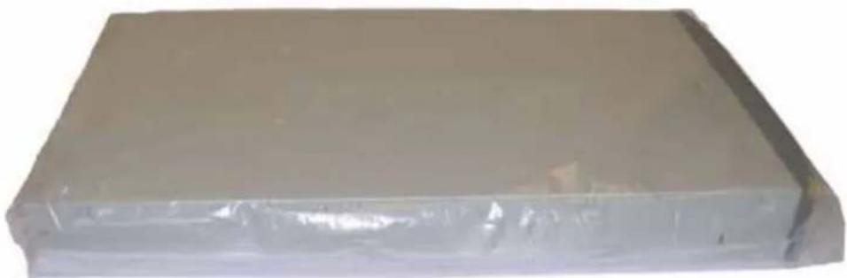
natural_image
Stacked rectangular plastic sheet with visible internal structure (no text or symbols)Figure D-11 Library in antistatic bag
- Put the foam cushions in the bottom of the box, as shown in Figure D-12.
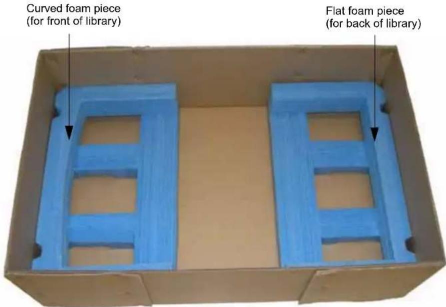
text_image
Curved foam piece (for front of library) Flat foam piece (for back of library)Figure D-12 Bottom foam packing pieces
- Place the library in the box, and then place the top foam piece on top of the library as shown in Figure D-13.
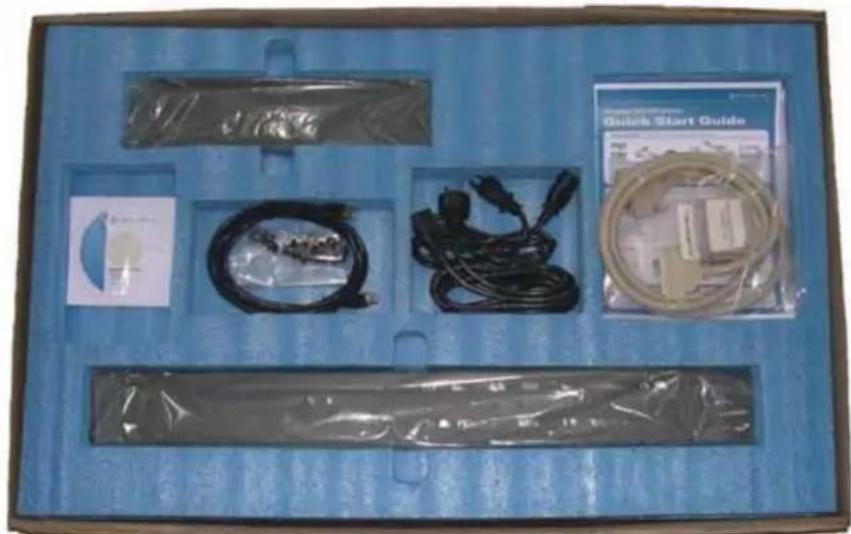
natural_image
Blue box containing medical or electronic equipment including a medical device, cables, and a quick start guide (no visible text or symbols on main objects)Figure D-13 Top foam packing piece (shown with accessories)
- If you are shipping the accessories with the library, insert them in the openings as shown in Figure D-13 and Figure D-14.
! Important
Do not ship accessories such as the power cord, Ethernet cable, SCSI cables, and terminator if you are returning the library for service. Include these items only if you are moving the library to a new location.
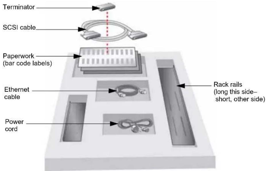
text_image
Terminator SCSI cable Paperwork (bar code labels) Ethernet cable Power cord Rack rails (long this side- short, other side)Figure D-14 Accessory item placement in shipping box
- Place any necessary paperwork on top of the die-cut piece.
- Place the top cover on the box and seal it securely with packing tape.
- Place the shipping label on the box.
E
ERROR MESSAGES
This appendix defines error messages that may appear on the library's front panel and provides corrective actions.

Caution
Most library components can be replaced only by Tandberg Data-approved service providers. If you cannot find an obvious cause for the problem, contact your service provider. Do not attempt to replace any components other than the tape drive(s) or the magazine(s). If you do, you will void your warranty.
! Important
Some corrective actions advise you to reset or power the library off and back on. To avoid disrupting communication between the host computer and other devices on the bus, make sure that there is no activity on the bus before you reset or power off the library.
If you need to power the library off, first unload the cartridge from the tape drive(s), if possible. If you power the library off and back on while a cartridge is in a tape drive, the tape drive may have to perform a lengthy format recovery process.
LIBRARY LCD ERROR MESSAGES
This section describes the general error messages that can appear on the library's operator panel and provides corrective actions.
TableE-1 lists library error messages in alphabetical order.
If the corrective action in the table:
▶ Instructs you to reset the library or tape drive, go to "Resetting the Library" on page 138 for instructions.
Does not correct the error, contact Tandberg Data Technical Support at www.tandbergdata.com or your service provider.
Table E-1 Library error messages
| Error Message Description | Corrective Action | |
| Auto Cleaning The tape | drive is performing an automatic cleaning of the tape drive using the cleaning cartridge in the fixed cleaning cell. | No action necessary. |
| Bad Cleaning Tape The | tape drive has determined that the cleaning cartridge is not the proper type for this tape drive. | Replace the cleaning cartridge with one that is compatible with this tape drive.Use only LTO cleaning cartridges with LTO tape drives. |
| Bad Configuration Configuration of drives does not match drives found in library. | 1. Verify that the tape drive settings in the “Drive configuration” menu match the type of drive(s) installed. See: “Reconfiguring the Library” on page 178.2. Check the ADI interface cabling and configuration. See “Connecting to SCSI” on page 17.3. Verify that the tape drive is operating correctly. See: “Tape Drive Troubleshooting” on page 202. | |
| Bad Download An error | occurred during a firmware upload to the library. | 1. Verify that you loaded the correct code. Do not load firmware from one model of library or library into another.2. Reset the library (see page 138) and reload the firmware.If the error persists, contact Tandberg Data Technical Support or your service provider. |
| Bootblock | An error occurred during firmware programing of the library. | 1. Verify that you loaded the correct code. Do not load firmware from one model of library or library into another.2. Reset the library (see page 138) and reload the firmware.If the error persists, contact Tandberg Data Technical Support or your service provider. |
| Busy | The library is executing a command issued from the backup application when a command is issued from the operator panel. | Wait until the library has finished its current operation, and then retry the requested operation. |
| Cartridge Misloaded | A cartridge was incorrectly loaded into the library. | Reload the cartridge. See “Inserting and Moving Cartridges” on page 120. |
| Circuit Failure | The library has detected a problem within its electronic circuitry. | 1. Power cycle the library.2. If the error persists, contact Tandberg Data Technical Support or your service provider. |
| Error Message | Description | Corrective Action |
| Command Error The options for the command were incorrect. | 1. Verify that the options for the command are valid. If they are not, correct the problem and retry the command.2. If they appear to be correct and the error persists, contact Tandberg Data Technical Support or your service provider. | |
| Communication The library is unable to communicate with the tape drive. | Check the ADI interface cabling and configuration. See “Connecting to SCSI” on page 17. | |
| Create File Fail | See “File Create Fail” on page 247 | |
| Device Not Ready The library is not ready to perform the requested operation because it is performing diagnostics or its power-on self-test (POST). | Wait until the library has finished, and then retry the operation. | |
| Dir Create Fail The library could not create a new directory on the USB device. | 1. Ensure that the USB device is securely inserted and retry the operation.2. Retry with another USB device.If the error persists, contact Tandberg Data Technical Support or your service provider. | |
| Disabled Sequential mode is not enabled. | Sequential mode has been disabled during execution of a sequential motion. Operator may need to unload cartridges using the front panel. See “Removing Cartridges from the Library” on page 126. | |
| Drive Command A command issued from the library to the tape drive failed. | ■Check the ADI interface cabling and configuration. See “Connecting to SCSI” on page 17.■Verify that the tape drive is operating correctly. See: “Tape Drive Troubleshooting” on page 202. | |
| Drive Communication The library is unable to communicate with the tape drive. | Check the ADI interface cabling and configuration. See “Connecting to SCSI” on page 17. | |
| Drive Empty The command cannot be completed because the tape drive does not contain a cartridge. | Do one of the following:■Load a cartridge in the tape drive and retry the operation.■If there are two tape drives installed in the library, select a tape drive that contains a cartridge and retry the operation. | |
| Drive Full The command | d cannot be completed because the tape drive already contains a cartridge. | Do one of the following:▪Unload the data cartridge, and then retry the operation. See “Unloading a Cartridge from a Tape Drive” on page 131.▪Wait until the current cartridge is unloaded by the application, and then retry the operation.▪If the library contains two tape drives, retry the operation on the second tape drive. |
| Drive Incompatible The | detected tape drive is incompatible with the library. | The StorageLibrary T24 library is only compatible with Ultrium 2 (LTO-2) and Ultrium 3 (LTO-3) tape drives. Ensure that you have one of these tape drives installed in the library. |
| Drive Load Failed The | cartridge couldn’t be loaded into the tape drive because of a mechanical problem or because of a broken tape. | 1. Export the tape from the library (see page 126) and verify that it is in good condition, and then retry the operation. Replace the cartridge if necessary.2. If the error persists, contact Tandberg Data Technical Support or your service provider. |
| Drive Timeout The tape | drive took too long to load or unload a tape, or the tape drive is not responding. | 1. If possible, use the operator panel to unloaded any cartridge that is in the tape drive (see page 131).2. Power the library off and back on to reset the tape drive.3. If the error persists, contact Tandberg Data Technical Support or your service provider. |
| Drive Unload Failed The | cartridge couldn’t be unloaded from the tape drive because of a mechanical problem. | 1. Power the library off and back on to reset the tape drive.2. Retry the unload operation once.3. If the error persists, contact Tandberg Data Technical Support or your service provider. |
| Expired Cleaning Tape | Cleaning tape in the fixed cleaning slot has been fully used. | Replace the cleaning cartridge with a new cleaning cartridge that is compatible with the installed tape drive(s).Use only LTO cleaning cartridges with LTO tape drives. |
| Failed Sequential mode | action failed. | 1. Enable Sequential mode. See “Setting the Library to Operate in Sequential Mode” on page 59.2. Retry the operation.If the error persists, contact Tandberg Data Technical Support or your service provider. |
| Error Message Description Corrective Action | ||
| File Close Fail The library could not close the USB file. | 1. Ensure that the USB device is securely inserted and retry the operation.2. Re-write the file to the USB device and retry the operation.3. Retry with another USB device.If the error persists, contact Tandberg Data Technical Support or your service provider. | |
| File Create Fail The library could not create a new file on the USB device. | 1. Ensure that the USB device is securely inserted and retry the operation.2. Re-write the file to the USB device and retry the operation.3. Retry with another USB device.If the error persists, contact Tandberg Data Technical Support or your service provider. | |
| File First Fail The library could not find the first file in the USB directory. | 1. Ensure that the USB device is securely inserted and retry the operation.2. Re-write the directory to the USB device and retry the operation.3. Retry with another USB device.If the error persists, contact Tandberg Data Technical Support or your service provider. | |
| File Flush Fail The library could not flush data written to the USB device. | 1. Ensure that the USB device is securely inserted and retry the operation.2. Re-write the file to the USB device and retry the operation.3. Retry with another USB device.If the error persists, contact Tandberg Data Technical Support or your service provider. | |
| File Next Fail The library could not find the next file in the USB directory. | 1. Ensure that the USB device is securely inserted and retry the operation.2. Re-write the directory to the USB device and retry the operation.3. Retry with another USB device.If the error persists, contact Tandberg Data Technical Support or your service provider. | |
| Error Message | Description | Corrective Action |
| File Open Fail The library | could not find the file on the USB device, or it could find the file, but not open it. | 1. Ensure that the selected file is present on the USB device.2. Ensure that the USB device is securely inserted and retry the operation.3. Re-write the file to the USB device and retry the operation.4. Retry with another USB device.If the error persists, contact Tandberg Data Technical Support or your service provider. |
| File Read Fail The library | could not read the next block of data from the USB device. | 1. Ensure that the USB device is securely inserted and retry the operation.2. Re-write the file to the USB device and retry the operation.3. Retry with another USB device.If the error persists, contact Tandberg Data Technical Support or your service provider. |
| File Seek Fail The library | could not seek to a specific offset within a USB file. | 1. Ensure that the USB device is securely inserted and retry the operation.2. Re-write the file to the USB device and retry the operation.3. Retry with another USB device.If the error persists, contact Tandberg Data Technical Support or your service provider. |
| File Write Fail The library | could not write the next block to the USB file. | 1. Ensure that the USB device is securely inserted and retry the operation.2. Retry the operation.3. Retry with another USB device.If the error persists, contact Tandberg Data Technical Support or your service provider. |
| General Failure An operation couldn't be completed because of an internal problem. | 1. Reset the library and retry the operation.2. If the error persists, contact your service provider. | |
| General HW Failure An operation couldn't be completed because of a mechanical problem. | 1. Reset the library and retry the operation.2. If the error persists, contact Tandberg Data Technical Support or your service provider. | |
| I/E Port Disabled The requested action cannot be done because the I/E port is disabled. | ■Determine that the I/E port should be disabled and try a new command.-or-■Enable the I/E port and retry the command.See the Product Manual. | |
| I/E Port Unlocked Import | ort/Export element is unlocked. | Close I/E Port and retry the operation. See “Loading Cartridges into the I/E Port” on page 120. |
| Invalid Cartridge An attempt was made to load an incompatible cartridge or a spent cleaning cartridge into a tape drive and the cartridge was ejected. | Remove the cartridge from the library and replace it with one that is compatible with the tape drive. See “Tape drive cartridge read/write compatibility” on page 119.If you were attempting to import a cleaning cartridge, insert a cartridge with cleaning cycles remaining on it. | |
| Invalid Data The library detected that the data read from the USB file is not the desired data. | Ensure that the correct data is in the file, re-write the file to the USB device, and retry the operation.Retry with another USB device.If the error persists, contact Tandberg Data Technical Support or your service provider. | |
| Invalid NVRAM An operation couldn’t be completed because the stored parameters are not valid. | Reset the library and retry the operation.Use “Restore Defaults” from the Library Settings menu to refresh the library settings.If the error persists, contact Tandberg Data Technical Support or your service provider. | |
| Invalid Password The password you entered does not match the saved password that is protecting this system. | Enter the valid password. See “Setting up an operator panel password” on page 78. | |
| Magazine Unlocked Magazine is unlocked. Close the magazine and retry the operation.See “Loading Cartridges into a Magazine” on page 124. | ||
| No Cleaning Tape The library cannot clean the tape drive since there is no cleaning cartridge in the fixed cleaning cell. | Import an LTO cleaning cartridge and then move it to the fixed cleaning cell.Use only LTO cleaning cartridges with LTO tape drives.See “Inserting and Moving Cartridges” on page 120. | |
| No Empty Cell The requested move cannot be completed because there is no empty cell to act as the destination for the move. | Use either SCSI or front panel commands to empty a cell and retry the command.Select a different type of element as the destination. | |
| No Empty Drive The requested move cannot be completed because there is no empty tape drive to act as the destination for the move. | Use either SCSI or front panel commands to empty a tape drive and retry the command.Select a different type of element as the destination. | |
| No Empty I/E Port The requested move cannot be completed because there is no empty I/E port to act as the destination for the move. | ■Use either SCSI or front panel commands to empty an I/E Port and retry the command.■Select a different type of element as the destination. | |
| No Enabled I/E Port The requested command cannot be completed because there is no enabled I/E port. | ■Enable an I/E port and retry the command.-or-■Select another command. | |
| No Medium Removal Media removal from the library has been prevented through the backup application. | ■Turn off media removal prevention from the backup application and retry the operation.■Reset the library and retry the operation. | |
| No USB Device The library does not see a USB device. | ■Ensure that the USB device is securely inserted and retry.■Try another USB device. | |
| Not Calibrated The manufacturing calibration of the library is not complete or has been compromised. | Contact Tandberg Data Technical Support or your service provider. | |
| Not Implemented The command is not implemented in this library. | No corrective action | |
| Operation Aborted The current operation was aborted by the host or user. | Retry the operation, if desired. | |
| Operation Stopped The current operation was stopped by the host or user. | Retry the operation, if desired. | |
| Operator Action You are required to intervene. Operator intervention required:■ New tapes needed■Correct error (see other errors in this table) | ||
| Over Temperature | The tape drive's temperature limit has been exceeded, and the cartridge has been ejected from the tape drive. | ■Wait until the library has cooled, and then unload the cartridge to a cell and re-load it into the tape drive.■Check the room temperature. The ambient temperature must be no more than 40°C (104°F).■Provide additional air flow around the library to improve cooling. |
| Owned by E-Net | The library is executing a command issued from the Remote Management utility (see Chapter 4) when a command is issued from the operator panel. | Wait until the library has finished its current operation, and then retry the operation. |
| Owned by Panel The library is executing a command issued from operator panel when a command is issued from the Remote Management utility (see Chapter 4). | Wait until the library has finished its current operation, and then retry the operation. | |
| Picker Ship-lock The robot could not move because it may be locked in place by the shipping lock. | Remove the shipping lock (see page 23). | |
| POST Failed The library encountered an error during its power-on self-test. | 1. Reset the library (see page 138) and retry the operation.2. If the error persists, contact Tandberg Data Technical Support or your service provider. | |
| Power Fan The library has detected that the power fan is not operating properly. | 1. Power cycle the library.2. If the error persists, contact Tandberg Data Technical Support or your service provider. | |
| Report Illegal Request | The I/E port door is unlocked. | Lock the I/E port door (press it firmly toward the library) and retry the operation.When the I/E port door is locked, the lock icon illuminates solid green ( ). |
| Reserve Failed The library could not reserve the USB device resources. | 1. Retry the operation.2. Reset the library (see page 138) and retry the operation.If the error persists, contact Tandberg Data Technical Support or your service provider. | |
| Reset Will Occur! When the operation completes, the library will reset itself as if a power-cycle had occurred. | ■If the operation has not started, proceed with the operation only if the reset will not cause a problem.■If the operation is underway, no action is necessary; the machine will reset itself. | |
| Right Cable | The library detected an error with the right-side cable. | Contact Tandberg Data Technical Support (see page iii) or your service provider. |
| Robot Empty | The robot is unexpectedly empty | 1. Reset the library (see page 138) and retry the operation.2. If the error persists, contact Tandberg Data Technical Support) or your service provider. |
| Robot Full The robot is unexpectedly full | 1. Reset the library (see page 138) and retry the operation.2. If the error persists, contact Tandberg Data Technical Support or your service provider. | |
| SCSI Error | An error occurred in the ADI/SCSI interface. | Check the ADI/SCSI cabling and configuration.See “Connecting to SCSI” on page 17. |
| SCSI Timeout A timeout | occurred in the ADI/SCSI interface. | Check the ADI/SCSI cabling and configuration.See “Connecting to SCSI” on page 17. |
| Sequential Mode The library is set to operate in Sequential Mode | Change to Random Mode and retry the operation. See “Setting the Library to Operate in Sequential Mode” on page 59. | |
| Service Busy The library is executing a command issued from the backup application when a command is issued from the operator panel. | Wait until the library has finished its current operation, and then retry the requested operation. | |
| Servo Failure The library’s cartridge handling mechanism (robot) has experienced a problem. | 1. Reset the library (see page 138) and retry the operation.2. If the error persists, contact Tandberg Data Technical Support or your service provider. | |
| Servo Jammed The library’s cartridge handling mechanism (robot) is jammed. | 1. Reset the library (see page 138) and retry the operation.2. If the error persists, contact Tandberg Data Technical Support or your service provider. | |
| Servo Timeout The library’s cartridge handling mechanism (robot) was unable to complete an operation within a specified time frame. | 1. Reset the library (see page 138) and retry the operation.2. If the error persists, contact Tandberg Data Technical Support or your service provider. | |
| Servo Unsafe The library’s cartridge handling mechanism (robot) has detected an unsafe situation for the media. | 1. Reset the library (see page 138) and retry the operation.2. If the error persists, contact Tandberg Data Technical Support or your service provider. | |
| Set Date Fail The library could not set the date on a USB file or directory. | 1. Ensure that the USB device is securely inserted and retry the operation.2. Retry with another USB device.If the error persists, contact Tandberg Data Technical Support or your service provider. | |
| Set Time Fail | The library could not set the time on a USB file or directory. | 1. Ensure that the USB device is securely inserted and retry the operation.2. Retry with another USB device.If the error persists, contact Tandberg Data Technical Support or your service provider. |
| Slot Empty | The command cannot be completed because the slot does not contain a cartridge. | Select a slot that has a cartridge and retry the operation. |
| Slot Full The command | cannot be completed because the slot already contains a cartridge. | Do one of the following:■Empty the slot and retry the operation.■Select a slot location that does not contain a cartridge and retry the operation. |
| Software Error The library | has experienced a fatal microcode error. | 1. Reset the library (see page 138) and retry the operation.2. If the error persists, contact Tandberg Data Technical Support or your service provider. |
| System Error The library | has experienced a fatal error. | 1. Reset the library (see page 138) and retry the operation.2. If the error persists, contact Tandberg Data Technical Support or your service provider. |
| System Fan The library | has detected that the system fan is not operating properly. | 1. Power cycle the library.2. If the error persists, contact Tandberg Data Technical Support or your service provider. |
| System Timeout An library | operation took too long. | 1. Reset the library (see page 138) and retry the operation.2. If the error persists, contact Tandberg Data Technical Support or your service provider. |
| Tape Overl ow The robot | is full and no empty slot can be found. | Remove one or more cartridges.See “Loading Cartridges into the I/E Port” on page 120 (to remove a single cartridge).See “Loading Cartridges into a Magazine” on page 124 (to remove multiple cartridges). |
| Terminated The operation | has been stopped by the user. | Retry the operation, if desired. |
| Unknown Drive | The library does not recognize the tape drive. | 1. Verify that the tape drive settings in the “Drive Configuration menu match the type of tape drive(s) installed.2. Ensure that you have a valid SCSI ID set for the tape drive. See “Changing the SCSI IDs” on page 52. |
LIBRARY "FATAL" ERROR MESSAGES
This section describes the “fatal” error messages that can appear on the library’s operator panel. If one of these errors occurs, the library goes into a halted state where only serial diagnostics communication is possible. The only recovery is to power-cycle the library: press the 0 on the back of the library (power off), and then press the I (power on).
Table Table E-2 lists the errors in alphabetical order.
▶ Fatal errors appear in the following format (see example below).
| Message Description |
| ! Fatal Error ! Heading |
| This text specifies the error |
| The code source file which is calling out the error |
| The line of code in the file which is calling out the error |
! Fatal Error!
Task watchdog expired
Table E-2 Library "fatal" error messages
| Error Message | Description | Corrective Action |
| Attempt to Read past end of Network NVRAM area | Illegal non-volatile RAM access | 1. Power-cycle the library: press the 0 on the back of the library (power off), and then press the I (power on).2. If the error persists, contact Tandberg Data Technical Support or your service provider. |
| Attempt to Write past end of Network NVRAM area | Illegal non-volatile RAM access | |
| BlockPoolxxxx creation failed | Unable to create data allocation pool xxxx | |
| Data Abort:xxxxxx | Data accesses at illegal location | |
| Drive | An invalid drive ID is being used internally | |
| DTE_IX | An invalid drive ID is being used to select a task | |
| Exceeded logging source maximum | An invalid module ID is being used internally | |
| FIQ ints can't be enabled | Illegal use of certain interrupts | |
| FIQ ints can't be disabled | Illegal use of certain interrupts | |
| FIQ ints can't be registered | Illegal use of certain interrupts | |
| FIQ ints can't be unregistered | Illegal use of certain interrupts | |
| FIQ req [xxxxxxxx] Illegal use of certain interrupts | ||
| Intrpt no handler registered | Received interrupt with no firmware handler | |
| Invalid thread requested for launch | Attempt to start an unknown task | |
| Pref abort:xxxxxxx Prefetch instruction abort occurred | ||
| RFQx Operating system failed reading from queue x | ||
| Sense data too big An internal data buffer has been made too small | ||
| Spurious interrupt Received invalid interrupt | ||
| Spurious Interrupt during flash programming | illegal interrupt is interrupting code update | |
| SW Int Expt [xxxxxxxx] Received illegal software interrupt | ||
| Task watchdog expired | Task failed to give up control of processor in a reasonable time | |
| Unable to allocate Buffer | Operating system has run out of allocatable data | |
| Unable to launch XXX Unable to start operating system task XXX | ||
| Undef Inst [xxxxxxxx] Executed an undefined processor instruction | ||
| Unknown [id:dd] generic interrupt | Received unknown interrupt | |
| Error Message Description | Correctional Action | |
| WatchDog timer expired | Firmware failed report to hardware | 1. Power-cycle the library: press the 0 on the back of the library (power off), and then press the I (power on).2. If the error persists, contact Tandberg Data Technical Support or your service provider. |
| WTQx Operating system | failed writing to queue x | |
INDEX
#
210 emulation mode 57
221L emulation mode 57
A
accessories 10
acoustic noise limits 214
ADI Command
about 219, 219
library LUN 17
LVD SCSI interface 2
SCSI IDs 52 to 53
SCSI interface bridge 54
advanced troubleshooting 208
agency compliance 215 to 217
agency declarations
Australia and New Zealand 217
Canadian Verification 216
European Community 217
FCC notice 216
GS mark 216
RoHS 217
Underwriters Laboratory 215
VCCI Class A 217
WEEE 217
altitude limits 213
application
See software
See software (backup application)
Autoclean option 65
automatic drive cleaning
setting up 63 to 67
via remote management 101
Automation/Drive Interface
See ADI Command
B
back panel components 5 to 6
backup application
See software
bar code labels
identifying the media 50
preparing 11
re-scanning 163
viewing contents 95, 158
bar code scanner 2, 7
bus
See SCSI bus
buttons
See keypad
C
cable requirements
Ethernet 227
international power 213
SCSI 220
capacity
data cartridges 209
library 209
cartridge
See also cartridges (information)
See also cartridges (inventory)
See also cartridges (using)
See also cleaning cartridge
See also WORM media
cartridge access port
See import/export port
cartridge handling mechanism (CHM) 7
cartridges (information)
purchasing 11
selecting 11
supported by tape drive 119
cartridges (inventory)
after power-on 23
after reset 139
time required 211
updating 163
viewing via RMU 95
viewing via the front panel 158 to 163
cartridges (using)
inserting 120 to 121
preparing 119
removing (power off) 181
removing (power on) 126
storing 140
viewing the cartridge type 50
cleaning
activating cleaning cartridge cell 63
enabling Autoclean option 63 to 67
library 183
setting up automatic drive cleaning 63 to 67
tape drive 133 to 138
cleaning cartridge
cleaning count via RMU 93
cleaning count via the front panel 133
requirements 119
storing in library 133 to 138
using 133 to 138
code load
See firmware
code version
library 141
tape drive 153
via Remote Management utility 89
compatible tape cartridges 119
components
back panel 5 to 6
front panel 3 to 4
internal 7
configuration (changing)
accessing options 33 to 39
automatic drive cleaning 63 to 67
changing from operator panel 39 to 84
changing through Remote Management utility 97
emulation mode 57 to 59, 99
Ethernet 67 to 74
LCD language 41
configuration (changing) continued
password 78 to 80
SCSI IDs 52 to 53
Sequential mode 59 to 63
using operator panel 33 to 38
using Remote Management utility 87 to 115
configuration (restoring default values)
via power reset 138 to 140
via the front panel 83 to 84
configuration (viewing)
checking setup 31, 84
menu overview 37 to 39
using operator panel 33 to 38
using Remote Management utility 87 to 115
creating diagnostic listings 193
D
data cartridges
See cartridges
Data Protect (SK 7h) error, WORM media 232
data transfer rate 210
demos
running library 188 to 190
running tape drive 183 to 184
DHCP
specifying 67 to 74
viewing address 141
diagnostics
creating listings for
troubleshooting 190 to 193
generating log files 208
running from operator panel 185
running through Remote Management
utility 107
dimensions
library 210
shipping container 215
drive
See tape drive
dump
See diagnostic listings
E
electrostatic discharge (ESD) 12
element addresses
changing 224
description 224
emulation mode
changing from operator panel 57 to 59
changing using Remote Management utility 99
description 57
environmental specifications 213
error messages on the LCD 243 to 253
errors
"fatal" messages on the LCD 254 to 256
Data Protect (SK 7h) error with WORM media 232
Medium Error (SK 3h) with WORM media 232
messages on the LCD 243 to 253
reported in software 204 to 205
Ethernet
cable requirements 11
configuring interface 67 to 74
connecting library to 21
creating diagnostic listings via FTP 190 to 193
upgrading firmware via FTP 190 to 192
USB options 41
using Remote Management utility 87 to 115
Ethernet configuration
changing from operator panel 67 to 74
changing through Remote Management utility 102
Ethernet port
cable requirements 227
connecting to 21
event log
See history
Exabyte 221L emulation mode 57
EZ17 Autoloader emulation mode 57
F
fan 6
features 1 to 2
Fibre Channel
connecting 20
connector description 6
interface specifications 226
firmware
updating tape drive via remote management 111
updating via remote management 108
upgrading for library via FTP 190 to 192
firmware continued
viewing library code level 141
viewing tape drive code level 153
WORM requirements 231
front panel components 3 to 4
FTP
connecting to interface 191
diagnostic logs 208
using to create diagnostic listings 192
using to upgrade firmware 190 to 192
G
gateway address 67 to 74
H
Home screen 34
humidity specifications 213
|
IDs
See SCSI
import/export port (I/E Port)
description 4
operating manually 181
using 120
inserting cartridges 120 to 121
installation (directions)
connecting the power cord 23
connecting to Ethernet 21
connecting to Fibre Channel 20
connecting to SCSI 17 to 18
powering on 22
rack-mounting 13 to 17
troubleshooting 199 to 201
verifying the hardware setup 30
installation (requirements)
accessories and equipment for 10 to 12
application software 12
environment 12
preparing for 12
interface specifications
Ethernet 227 to 227
Fibre Channel 226
SCSI 219 to 225
internal components 7
inventory
See viewing cartridge inventory
IP address 67 to 74
K
keypad (front panel buttons)
description 3
using 33 to 38
L
language, LCD 41
LCD
changing language 41
description 3
error messages 243 to 256
See also operator panel
LED, status 4, 118
library (configuration)
configuration via remote
management 96 to 104
Remote Management utility 87 to 115
See also configuration
Sequential mode 59 to 63
tape drive configuration 178
library (information)
back panel components 5
front panel components 3
LUN 17
product overview 1
SCSI interface bridge 54
statistics via remote
management 105 to 107
viewing history 144
viewing information 141 to 148
library (maintenance)
cleaning 183
cleaning tape drive 133 to 138
creating diagnostic listings 190 to 196
moving or shipping the library 233 to 242
performing a digital self test 185
performing a motion test 186
replacing the tape drive 165 to 181
running a system demo 188
troubleshooting 206
library (updating)
updating code via remote management 108
upgrading firmware 190 to 196
LibTool
advanced troubleshooting 208
download URL 193
upgrading library firmware 193
viewing current inventory 201
loader, cartridge handling mechanism 7
LTOTool
advanced troubleshooting 208
creating diagnostic logs 196
download URL 208
upgrading tape drive firmware 196
LVD SCSI
connecting 17
description of library interface 2
library cable requirements 10, 220
troubleshooting tips 200
M
magazines 7
maintenance
cleaning library 183
cleaning tape drive 133 to 138
creating diagnostic listings 190 to 196
moving the library 233 to 242
replacing the tape drive 165 to 181
upgrading firmware 190 to 196
viewing library history 144
media
See cartridges
See WORM media
media related errors 230
Medium Error (SK 3h), WORM media 232
menu
home screen 39
overview 37 to 39
moving the library 233 to 242
N
Native emulation mode 57
noise limits 214
O
operating environment specifications 213
operation (general)
preparing cartridges 119
resetting library and tape drive 138 to 140
operation (general) continued
See also operation (library)
See also operation (tape drive)
using Remote Management utility 87 to 115
viewing library and tape drive
information 141 to 163
operation (library)
inserting cartridges 120 to 121
powering on library 22
removing cartridges (power off) 181
removing cartridges (power on) 126
running library demos 188 to 190
Sequential mode 59 to 63
using import/export port (I/E
Port) 120 to 121
using operator panel 33 to 38
operation (tape drive)
cleaning the tape drive 133 to 138
running tape drive demos 183 to 184
unloading cartridge from tape drive 131
operation mode
emulation 57
Random or Sequential 59
operator panel
Home screen 34
location 3
menu overview 37 to 39
preventing access to menus 78 to 82
using 33 to 38
P
packing for shipment 240 to 242
particulate limits 214
password
accessing password-protected menus 80
disabling for operator panel 81
setting for operator panel 78 to 82
setting for Remote Management utility 104
performance specifications 210 to 212
Performing Diagnostic Tests 190
power consumption 212
power cord
connecting 22
international requirements 213
specifications 212
power switch 6
powering on the library 22
preparing cartridges 119
product warranty caution iii
R
rack mounting
installation 13 to 17
removing from rack 239
Random mode
See also Sequential mode 59
regulatory agency compliance 215 to 217
reliability specification 212
Remote Management utility
accessing 87
configuration options 96
connecting to Ethernet 21
description 2
setting Ethernet configuration 67
statistics page 105
tools and tests 107
using 87 to 115
removing cartridges
with power off 181
with power on 126
resetting library and tape drive 138 to 140
returning library for service 233 to 242
RMA number, obtaining 233
S
safety agency compliance 215 to 217
SCSI
changing IDs 52 to 53
commands 221
interface specifications 219 to 225
library interface (bridge) 54
See also SCSI bus
See also SCSI cable
terminator installation 18
terminator requirements 10
SCSI (bus)
LVD configuration 17
terminator requirements 10
troubleshooting 206
SCSI (cable)
connecting 17 to 18
length restrictions 18
requirements 10, 220
SCSI host bus adapter card 12
security
accessing password protected menus 80
disabling operator panel password 81
setting operator panel password 78 to 80
setting Remote Management utility password 104
Sequential mode 59 to 63
serial number
library 141
tape drive 153
service
returning the library 233 to 242
shipping lock, removing 23
shipping specifications 215
shipping the library 233 to 242
shock limits 214
single-character display
error codes and messages with WORM media 230
size
library 210
shipping container 215
software
backup applications 57, 200
cleaning the tape drive 132
does not support library (emulation) 57
installing 12
loading cartridges 129
Remote Management utility 87 to 115
using application's cleaning option 135
software (backup applications)
See also software
See your software documentation
specifications
agency compliance 215 to 217
capacity 209
data transfer rate 210
environmental 213
performance 210 to 212
power 212
reliability 212
shipping 215
size 210
weight 210
statistics
library 141
viewing through Remote Management utility 105
status LED 4,118
storage capacity
data cartridge 209
library 209
storing cartridges 140
subnet mask 67 to 74
T
Tandberg Data LibTool
download URL 193
upgrading firmware 193
viewing current inventory 201
Tandberg Data LTOTool
advanced troubleshooting 208
creating diagnostic listings 196
download URL 208
upgrading tape drive firmware 196
Tandberg Data, contacting iii
tape drive (information)
brand and serial number 153
code version 153
description 2
location 7
serial number 153
viewing operation information 148 to 150
tape drive (maintenance)
cleaning 133 to 138
cover plate location 5
performing a self test 183
replacing 165 to 181
resetting 138 to 140
setting configuration 178
troubleshooting 206
tape drive (operation)
running a self test 185
tape drive (using)
firmware requirements for using
WORM 231
loading and unloading
cartridges 129 to 132
setting SCSI ID 52
updating code via remote management 111
TapeAlert flags 231
tapes
See cartridges
Technical Support
gather required information before
contacting 206 to 208
temperature, operating 213
termination, SCSI
installing terminator 18
terminator requirements 10
transfer rate 210
troubleshooting 199 to 208
Write Once, Read Many (WORM) media
characteristics 229
data security 230
errors 230
specifications 230
U
Universal Serial Bus (USB)
connecting library to 21
interface support 215
options 41
V
viewing (cartridge inventory)
via front panel 158 to 163
via Remote Management utility 95
viewing (library)
cartridge inventory 158
history (event logs) 144
serial number and code level 141
settings 152
statistics 146
status 143
viewing (tape drive)
configuration 156
SCSI ID 155
SCSI interface (bridge) 157
serial number 153
W
warranty
product warranty caution iii
weight
library 210
shipping 215
warning 16
wide SCSI
connecting 17
library requirements 10, 220
worldwide cartridge identifier (WWCID) 229
Write Once, Read Many (WORM) capability
firmware requirements 231
overview 229, 243