
EWS357AP - Access Point ENGENIUS - Free user manual and instructions
Find the device manual for free EWS357AP ENGENIUS in PDF.


| Product Type | Wi-Fi Access Point |
| Brand | EnGenius |
| Model | EWS357AP |
| Wi-Fi Standards | 802.11a/b/g/n/ac Wave 2 |
| Frequency Bands | 2.4 GHz and 5 GHz |
| Maximum Data Rate | Up to 300 Mbps (2.4 GHz) + 867 Mbps (5 GHz) |
| MIMO | 2x2 |
| Power Supply | PoE 802.3af or 12 V DC power adapter (not included) |
| Power Consumption | 6 W max |
| Dimensions (W × D × H) | 160 × 160 × 35 mm |
| Weight | 320 g |
| Operating Temperature | 0 °C to 50 °C |
| Operating Humidity | 10 % to 90 % non-condensing |
| Mounting Method | Ceiling or wall (kit included) |
| Ports | 1 × Gigabit Ethernet (PoE in), 1 × console port |
| Wireless Security | WPA2-PSK, WPA3-SAE, WPA2-Enterprise, MAC filtering, built-in firewall |
| Management | Web interface, CLI (SSH), SNMP v1/v2c/v3 |
| VLAN | 802.1Q, up to 16 VLANs |
| Maintenance and Cleaning | Disconnect the device, clean with a soft dry cloth. Do not use harsh chemicals. |
| Spare Parts and Repairability | No spare parts available. The device must be returned to the manufacturer for repair. |
| General Information | Compliant with IC RSS-247 standards. Indoor use only in 5 GHz band. Minimum safety distance: 20 cm. |
Frequently Asked Questions - EWS357AP ENGENIUS
User questions about EWS357AP ENGENIUS
0 question about this device. Answer the ones you know or ask your own.
Ask a new question about this device
Download the instructions for your Access Point in PDF format for free! Find your manual EWS357AP - ENGENIUS and take your electronic device back in hand. On this page are published all the documents necessary for the use of your device. EWS357AP by ENGENIUS.
USER MANUAL EWS357AP ENGENIUS
11ax Indoor Ceiling Mount Managed Access Point
IMPORTANT
To install this Access Point please refer to the Quick Installation Guide included in the product packaging.
Table of Contents
Chapter 1 Product Overview.... 4
Key Features/Introduction.... 5
System Requirements.... 6
Package Contents.... 6
Technical Specifications.... 7
Physical Interface....9
Chapter 2 Before You Begin....10
Computer Settings.... 11
Hardware Installation 15
Mounting the AP....
Chapter 3 Configuring Your Access Point.... 18
Default Settings./Web Configuration.... 19
Chapter 4 Building a Wireless Network.... 20
Access Point Mode.... 21
Chapter 5 Status....22
Main Status.... 23
Connection.... 25
Chapter 6 Network 27
Basic IPv4/IPv6 Settings.... 28
Spanning Tree Protocol Setting.... 29
Chapter 7 2.4 GHz/5 GHz Wireless.... 30
Wireless Settings.... 31
Band Steering.... 31
2.4 GHz/5 GHz Wireless Network.... 32
2.4GHz/5 GHz SSID Profile.... 33
Wireless Security.... 34
Wireless Traffic Shaping 36
Wireless MAC Filtering.... 37
Fast Roaming.... 38
Guest Network Settings.... 39
Chapter 8 Management ...... 40
Management VLAN Settings.... 41
Advanced Settings.... 42
CLI Settings/Email Alert 42
Time Zone 45
Auto Reboot Settings.... 46
Wi-Fi Scheduler.... 47
16 Tools.... 4:
Account/Firmware.... 51
Backup/Restore 52
Log.... 5
Logout/Reset.... 55
Appendix.... 56
FCC Interference Statement.... 57
IC Interference Statement.... 58
FCC Interference Statement.... 60
Chapter 1
Product Overview
Introduction
Key Features - EWS357AP nad EWS377AP
- EWS357AP: Supports IEEE802.11ax/ac/a/b/g/n wireless standards with up to 574 Mbps data rate on 2.4GHz band and 1200 Mbps on 5GHz bands.
- EWS377AP: Supports IEEE802.11ax/ac/a/b/g/n wireless standards with up to 1148 Mbps data rate on 2.4GHz band and 2400 Mbps on 5GHz bands.
• Support MU-MIMO function on both 2.4GHz and 5GHz radio.
• Support Tx Beamforming to enlarge the transmitting distance. - Perform 1024-QAM to increase 25% better throughput compare to 802.11AC 256-QAM.
- Systemic and distributed management over EnGenius ezMaster and EWS Management switch without licensing or subscription. fee.
- More customized items on Band Steering for intelligent Management.
- Perform one-click update to deliver a configuration over multi-segments for these managed Access Points.

natural_image
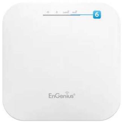
Exterior view of a white EnGenius-branded electronic device (no visible text or symbols on the device body)Introduction
EWS managed APs are dual-band wireless 802.11 ax/ac/a/b/g/n wireless Access Point that built in powerful interfaces to achieve great performance and evenly coverage under a pervasive environment. It can be configured as an: Managed mode or Stand-alone mode to network with multiple client devices including mobile, NB and other client devices for providing an optimal connecting spped which could be the best choice to pro-users, SMB, hotel, hospital and enterprise. Its high-powered, long-range characteristics make it a cost-effective alternative to ordinary Access Points that do not have the range and reach to connect to a growing number of wireless users who wish to connect to a business network.
Maximum data rates are based on IEEE 802.11 standards. Actual throughput and range may vary depending on many factors including environmental conditions, distance between devices, radio interference in the operating environment, and mix of devices in the network. Features and specifications subject to change without notice. Trademarks and registered trademarks are the property of their respective owners. For United States of America: Copyright © 2019 EnGenius Technologies, Inc. All rights reserved.
To protect sensitive data during wireless transmissions, the device offers different encryption settings for wireless transmissions, including industry standard WPA2 encryption. The device also includes MAC address filtering to allow network administrators to offer network access only to known computers and other devices based on their MAC addresses.
System Requirements
The following are the Minimum System Requirements in order to configure the device.
- Computer with an Ethernet interface or wireless network capability
- Windows OS (XP, Vista, 7, 8, 10), Mac OS, or Linux-based operating systems
- Web-Browsing Application (i.e.: Edge, Internet Explorer, Firefox, Safari, or another similar browser application)
Package Contents
- Access Point
• Ceiling Mount Base (9/16" T-Rail)
• Ceiling Mount Base (15/16" T-Rail) - Mounting Screw Kit
- Quick Installation Guide
*(all items must be in package to issue a refund):
Technical Specifications (EWS357AP/EWS377AP)
Standard:
IEEE802.11ax/ac/a/n on 5 GHz
IEEE802.11ax/b/g/n on 2.4 GHz
Antenna
Integrated Omni-directional antennas
Physical Interfaces
EWS357AP: 1 x 10/100/1000 Ethernet Port with PoE support
EWS377AP: 1 x 10/100/1000/2500 Ethernet Port with PoE support
LED Indicators
Power
LAN 1
LAN 2
2.4 GHz
5 GHz
Power Requirements
EWS357AP: DC12V/1.5A from adapter or Proprietary 54V from PoE
EWS377AP: DC12V/2A from adapter or Proprietary 54V from PoE
Operation Modes
Managed Mode
Stand alone Mode
Exquisite RF Management
Backgorund Scanning
Auto Transmit Power
Auto Channel Selection
Fast Roaming (802.11K)
Band Steering
RSSI Threshold
Optimize Performance
Quality of Service (QoS): Follow 802.11e
Power Save Mode (UAPSD)
Pre-Authentication (Compliance with 802.11i&x)
PMK Cahcing (Compliance with 802.11i)
Fast Roaming (802.11r)
Multicast/Unicast Conversion
Easy to Management
BSSID
Multiple SSIDs
Guest Network
VLAN Tag
VLAN Per SSID
Management VLAN
Captive Portal (Support on Manged mode)
Finger Printing (support on Managed Mode)
Traffic Shaping Per user / Per client
MAC Address Filtering
E-Mail Alert
Save Configuration as Users Default
Wi-Fi Scheduler (Support on Managed mode)
SNMP V1/V2c/V3
MIB I/II, Private MIB
Clients Statistics
RADIUS Accounting
Comprehensive Protection
Wireless encryption standard
Hidden SSID in beacons
Rogue AP Detection (Support on Manged mode)
L2 Isolation
Client Isolation
Https
SSH tunnel
Security
WPA2 Personal (AES)
WPA2 Enterprise (WPA-PSK AES)
Hides SSID in beacons
MAC address filtering, up to 32 MACs per SSID
Wireless STA (Client) connection list
Https Support
SSH Support
Physical/Environment Conditions
Operating:
Temperature: 0 °C to 40 °C (32 °F to 158 °F)
Humidity (non-condensing): 90% or less
Storage:
Temperature: -40 °C to 80 °C (-40 °F to 176 °F)
Humidity (non-condensing): 90% or less
Physical Interface (EWS357AP)
Dimensions and Weights
Length:160 mm (6.30")
Width: 160 mm (6.30")
Depth: 34 mm (1.34")
Weight: 370 g (0.75 lbs)


1 Latch: Fix mounting when sliding bracket into this slot
2 Reset Button: Push this button to reset or reboot this device
3 LAN Port (Proprietary 54V/0.6A or 802.3af): Ethernet port for RJ-45 cable.
4 DC-Jack: Powered from a DC12V/1.5A adapter
5 Ceiling Mount Holes: Use these ports to assemble with mounting bracket
6 LED Indicators: LED lights for Power, LAN Port, 2.4 GHz Connection and 5 GHz Connection.
Physical Interface (EWS377AP)
Dimensions and Weights
Length:205.73 mm (8.10")
Width: 205.73 mm (8.10")
Depth: 33.25 mm (1.31")
Weight: 597 g (1.32 lbs)

1 Latch: Fix mounting when sliding bracket into this slot
2 Reset Button: Push this button to reset or reboot this device
3 LAN Port (Proprietary 54V/0.6A or 802.3at): Ethernet port for RJ-45 cable.
4 DC-Jack: Powered from a DC12V/2A adapter
5 Ceiling Mount Holes: Use these ports to assemble with mounting bracket
6 LED Indicators: LED lights for Power, LAN Port, 2.4 GHz Connection and 5 GHz Connection.
Chapter 2
Before You Begin

Computer Settings
Windows XP/Windows 7/Windows 8/Windows 10
In order to use the Access Point, you must first configure the TCP/IPv4 connection of your Windows OS computer system.
1a. Click the Start button and open the Control Panel

Windows XP Windows 7

1b. Move your mouse to the lower right hot corner to display the Charms Bar and select the Control Panel in Windows 8 OS.

Windows 8
1c. In Windows 10, click Start to select All APPs to enter the folder of Windows system for selecting Control Panel.

Windows 10
2a. In Windows XP, click Network Connections.

Network Connections
2b. In Windows 7/Windows 8/Windows 10, click View Network Status and Tasks in the Network and Internet section, then select Change adapter settings.

Network and Internet View network status and tasks Choose homegroup and sharing options

- Right click on Local Area Connection and select Properties.

- Select Internet Protocol Version 4 (TCP/IPv4) and then select Properties.

- Select Use the following IP address and enter an IP address that is different from the Access Point and Subnet mask, then click OK.
Note: Ensure that the IP address and Subnet mask are on the same subnet as the device.
For example: EWS35xAP IP address: 192.168.1.1
PC IP address: 192.168.1.2 - 192.168.1.255
PC Subnet mask: 255.255.255.0

Apple Mac OS X
- Go to System Preferences (Which can be opened in the Applications folder or selecting it in the Apple Menu).
- Select Network in the Internet & Network section.

-
Highlight Ethernet.
-
In Configure IPv4, select Manually.
- Enter an IP address that is different from the Access Point and Subnet mask then press OK.
Note: Ensure that the IP address and Subnet mask are on the same subnet as the device.
For example: AP IP address: 192.168.1.1
PC IP address: 192.168.1.2 - 192.168.1.255
PC Subnet mask: 255.255.255.0
- Click Apply when done.

Hardware Installation
- Connect one end of the Ethernet cable into the LAN port of the Access Point and the other end to the Ethernet port on the computer.
- Connect a Power cord with the PoE Adapter and plug the other end into an electrical outlet.
- Connect the second Ethernet cable into the LAN port of this PoE Adapter and the other end to the Ethernet port on the computer.
Note1: The Access Point can be powered by 802.3af/at PoE (Power over Ethernet). You can consider to adopt
EnGenius EPA5006GP or EPA5006GAT for powering up your 11AX device.
Note2: EWS357AP can be driven by IEEE 802.3af and EWS377AP should be driven by IEEE802.3at.

Mounting the AP
Using the provided hardware, the AP can be attached to a wall or a ceiling.
- Managed Indoor Access Point
-
Mounting Screw Kit
-
Ceiling Mount Base (9/16" T-Rail)

- Ceiling Mount Base (15/16" T-Rail)


Ceiling Mount an Access Point
1) Slide the ceiling mount base into the slot of the Access Point.
2) Hold the Access Point with one hand to reach the other hand over the T-Rail sides of the bracket. Then hook the stationary end of the ceiling mount bracket onto the T-Rail.
1

natural_image
Diagram showing a device component before and after assembly, with no visible text or symbols2

natural_image
Technical line drawing of a mechanical assembly with no visible text or symbolsWall Mount an Access Point
3) Continued from A, determine where the Access Point to be placed and mark location on the surface for the two mounting holes. Use the appropriate drill bit to drill two 8.1mm diagram and 26mm depth holes in the markings and hammer the bolts into the openings.
4) Screw the anchors unto the holes until they are flush with the wall; screw the included screws into the anchors.h
5) Place the Access Point against wall with the mounting screw heads.

5
Chapter 3
Configuring Your Access Point

Configuring Your Access Point
This section will show you how to configure the using the web-based configuration interface.
Default Settings
Please use your Ethernet port or wireless network adapter to connect the Access Point.
| IP Address | 192.168.1.1 |
| Username / Password | admin / admin |
Web Configuration
- Open a web browser (Internet Explorer/Firefox/Safari/Chrome) and enter the IP Address http://192.168.1.1

Note: If you have changed the default LAN IP Address of the Access Point, ensure you enter the correct IP Address.
devThe default username and password are admin. Once you have entered the correct username and password, click the Login button to open the web-base configuration page.

* The model will be varied by different models.
- If successful, you will be logged in and see the User Menu of this Access Point.
Chapter 4
Building a Wireless Network
Access Point Mode
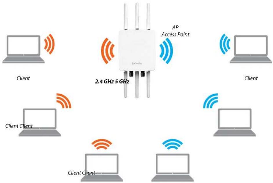
In Access Point Mode, AP behaves likes a central connection for stations or clients that support IEEE 802.11ac/a/b/g/n networks. The stations and clients must be configured to use the same SSID (Service Set Identifier) and security password to associate with the AP. The AP supports up to eight SSIDs per band at the same time for secure access.
Chapter 5
Status

Overview
Save Changes
This page lets you save and apply the settings shown under Unsaved changes list, or Revert the unsaved changes and revert to the previous settings that were in effect.

Device Status
Clicking the Device Status link under the Overview menu shows the status information about the current operating mode.
- The Device Information section shows general system information such as Device Name, MAC Address, Current Time, Firmware Version, and Management VLAN ID
Note: VLAN ID is only applicable in Access Point, WDS AP or WDS BR mode.
Device Information
| Device Name | ENS620EXT |
| MAC Address | |
| - LAN1 | 88:DC:96:00:00:10 |
| - LAN2 | 88:DC:96:00:00:11 |
| - Wireless LAN - 2.4GHz | 88:DC:96:00:00:12 |
| - Wireless LAN - 5GHz | 88:DC:96:00:00:13 |
| Country | USA |
| Current Local Time | Tue Jul 12 11:45:00 2016 |
| Uptime | 0h 4m 57s |
| Firmware Version | 1.0.0 |
| Management VLAN ID | Untagged |
- The Memory Information section shows usage of memory such as Total Available, Free, Cached, Buffered
Memory Information
- The LAN Information section shows the Local Area Network settings such as the LAN IP Address, Subnet mask, Primary DNS Address, Secondary DNS Address, status of DHCP client, and status of Spanning Tree protocol (STP).
LAN Information - IPv4
| IP Address | 192.168.1.1 |
| Subnet Mask | 255.255.255.0 |
| Gateway | 192.168.1.1 |
| Primary DNS | 0.0.0.0 |
| Secondary DNS | 0.0.0.0 |
| DHCP Client | Disable |
| Spanning Tree Protocol(STP) | Disable |
Wireless LAN Information - 2.4GHz
| Operation Mode | Access Point | |||
| Wireless Mode | 802.11 B/G/N | |||
| Channel Bandwidth | 20 MHz | |||
| Channel | 2.412 GHz(Channel 1) | |||
| Profile | SSID | Security | VID | 802.1Q |
| #1 | EnGenius_Test | None | 1 | Disable |
| #2 | EnGenius-mac_,2-2.4GHz | None | 2 | Disable |
| #3 | EnGenius-mac_,3-2.4GHz | None | 3 | Disable |
| #4 | EnGenius-mac_,4-2.4GHz | None | 4 | Disable |
| #5 | EnGenius-mac_,5-2.4GHz | None | 5 | Disable |
| #6 | EnGenius-mac_,6-2.4GHz | None | 6 | Disable |
| #7 | EnGenius-mac_,7-2.4GHz | None | 7 | Disable |
| #8 | EnGenius-mac_,8-2.4GHz | None | 8 | Disable |
| #9 | EnGenius-2.4GHz_GuestNetwork | None | Disable | |
The Wireless LAN Information 2.4 GHz/5 GHz section shows wireless information such as Operation Mode Frequency, and Channel. Since this Access Point supports multiple-SSIDs, information about each SSID, the ESSID, and security settings, are displayed
Note: Profile Settings are only applicable in Access Point and WDS AP modes.
Wireless LAN Information - 5GHz
| Operation Mode | WDS Access Point | |||
| Wireless Mode | 802.11 N/AC | |||
| Channel Bandwidth | 80 MHz | |||
| Channel | 5.180 GHz(Channel 36) | |||
| Profile | SSID | Security | VID | 802.1Q |
| #1 | EnGenius_Test | None | 51 | Disable |
| #2 | EnGenius-mac., 2-SGHz | None | 52 | Disable |
| #3 | EnGenius-mac., 3-SGHz | None | 53 | Disable |
| #4 | EnGenius-mac., 4-SGHz | None | 54 | Disable |
- The Statistics section shows Mac information such as SSID, MAC address, RX and TX.
Statistics
| SSID | MAC | RX(Packets) | TX(Packets) |
| Ethernet | 88:DC:96:00:00:10 | 134.37 KB(829 Pkts.) | 893.75 KB(857 Pkts.) |
| EnGenius-mac_1-2.4GHz | 88:DC:96:00:00:12 | 0.00 B(0 Pkts.) | 21.34 KB(149 Pkts.) |
| EnGenius-mac_1-5GHz | 88:DC:96:00:00:13 | 0.00 B(0 Pkts.) | 8.02 KB(44 Pkts.) |
Connections Realtime
2.4 GHz/5 GHz Connection List
Click the connection link under the Overview menu displays the connection list of clients associated to the AP's 2.4 GHz/5 GHz, along with the MAC addresses and signal strength for each client. Clicking Refresh updates the client list.
Note: Only applicable in Access Point and WDS modes.
2.4 GHz/5 GHz WDS Link List
Click the connection link under the Overview menu. page displays the current status of the WDS link, including WDS Link ID, MAC Address, Link Status and RSSI.
Note: Only applicable in WDS AP and WDS Bridge modes.
Connection List - 2.4GHz
| SSID | MAC Address | TX | RX | RSSI | Block |
| WDS Link List - 5GHz | |||||
| WDS Link ID# | MAC Address | Link Status | RSSI(dBm) | ||
| Refresh | |||||
Realtime
The Realtime section contains the following options:
CPU Loading: 3 minutes CPU loading percentage information, it displays current loading, average loading and peak loading status. Left bar is loading percentage; button is time tracing. Interval is every 3 seconds
AP

line
| Time Interval | CPU Loading (%) | | ------------- | -------------- | | Current | 5 | | Average | 5 | | Peak | 8 |Traffic Loading: 2.4GHz and 5GHz and Ethernet port inbound and outbound traffic by current, average and peak time.

line
| Time Interval | Throughput (kB/s) | | ------------- | ----------------- | | 0 | 0.11 | | Peak | 0.54 |Realtime Connection (Pkts): Overview on current active network connections. It displays UDP and TCP packets information and other connection status. UDP connections curve is in blue; TCP connection curve is in green; others curve is in red. Below of chart shows connections source and destination.
Chapter 6 Network

Basic
IPv4/IPv6 Settings
This page allows you to modify the device's IP settings.
IPv4 Settings
| IP Network Setting | DHCP * Static IP |
| IP Address | 192.168.1.1 |
| Subnet Mask | 255.255.255.0 |
| Gateway | 192.168.1.1 |
| Primary DNS | 0.0.0.0 |
| Secondary DNS | 0.0.0.0 |
IPv6 Settings Link-local Address
| IP Address | |
| Subnet Prefix Length | |
| Gateway | |
| Primary DNS | |
| Secondary DNS |
IP Network Settings: Select whether the device IP address will use a static IP address specified in the IP address field or be obtained automatically when the device connects to a DHCP server.
IP Address: The IP address of this device.
Subnet Mask: The IP Subnet mask of this device.
Gateway: The Default Gateway of this device. Leave it blank if you are unsure of this setting.
Primary/Secondary DNS: The primary/secondary DNS address for this device.
Save: Click Save to confirm the changes.
Spanning Tree Protocol (STP) Settings
This page allows you to modify the Spanning Tree settings. Enabling the Spanning Tree protocol will prevent network loops in your LAN network.
Spanning Tree Protocol (STP) Settings
| Status | Enable + Disable | |
| Hello Time | 2 | seconds (1-10) |
| Max Age | 20 | seconds (6-40) |
| Forward Delay | 15 | seconds (4-30) |
| Priority | 32768 | (0-65535) |
Spanning Tree Status: Enables or Disables the Spanning Tree function. Default is Disable.
Hello Time: Specifies Bridge Hello Time in seconds. The value determines how often the device sends handshake packets to communicate information about the topology throughout the entire Bridged Local Area Network.
Max Age: Specifies Bridge Max Age in seconds. If another
bridge in the spanning tree does not send a hello packet for a long period of time, it is assumed to be inactive.
Forward Delay: Specifies Bridge Forward Delay in seconds. Forwarding delay time is the time spent in each of the Listening and Learning states before the Forwarding state is entered. This delay is provided so that when a new bridge comes onto a busy network, it analyzes data traffic before participating in the network.
Priority: Specifies the Priority Number. A smaller number has a greater priority than a larger number.
Save: Click Save to confirm the changes.
Chapter 7
2.4 GHz & 5 GHz Wireless

Wireless
Wireless Settings
Device Name: Enter a name for the device. The name you type appears in SNMP management. This name is not the SSID and is not broadcast to other devices.
Band Steering: Enable Band Steering to send 802.11n clients to the 5 GHz band, where 802.11b/g clients cannot go, and leave 802.11b/g clients in 2.4GHz to operate at their slower rates. Before implementing this feature, we suggest you to assure the both 2.4GHz and 5GHz SSID, as well as security settings must be the same. EnGenius Band Steering supports following advanced settings,
*Force 5GHz: When band steering is configured to Force 5GHz mode, the AP will not dual band capable client devices to network to the 2.4GHz band only if the client devices are not currently associated on 2.4GHz radio in this AP.

*Prefer 5GHz: When band steering is configured to Prefer 5GHz mode, the AP will steer dual band capable client
devices to 5GHz radio when the RSSI value of these client devices on 5GHz radio is more than set one. The allowed RSSI value for default setting is -75dBm.

*Band Balance: When band steering is configured to Band Balance mode, the AP will steer dual band capable client devices to 5GHz when the RSSI value of these client devices on 5GHz radio is more than set one. To evenly allocate RF resource on the both 2.4GHz and 5GHz radios, users also can set the portion of client devices on 5GHz radio to assure smoothly connection. The default value of the 5GHz radio is 75%.
Save: Click Save to confirm the changes.
This page displays the current status of the Wireless settings of this AP.
2.4 GHz/5 GHz Wireless Network

Operation Mode: EWS 4x4 devices support Access Point currently.
Wireless Mode: Scrow down this list to select wireless broadcasting standard on 2.4GHz and 5GHz frequency bands.
Channel HT Mode: Scrow down this list to select bandwidth for operating under a frequency band. The default channel bandwidth is 20 MHz on 2.4GHz frequency radio and 40 MHz on 5GHz frequency radio. Considering the different applications, users can decide to implement a channel bandwidth to fulfill real applications. The larger the channel, the greater the transmission quality and speed.
Transmit Power (Tx Power): Default Tx power is Auto to obey regulatory power of each country.
Channel: Click Configuration button to open a new windows to configure channels for performing wireless service.

Save current setting(s)
*Default configuration: Default setting of channel selection is "All" to perform auto channel on the exis channel list.
*None: Click "None" to disable the setting on this radio. This radio is disabled.
*Group Configuration: Click specific groups of channels for performing auto channel function. For example, users can click U-NII-1 and U-NII-3 to perform auto channel on these bands; the mechanism of this AP will select the relatively optimal channel to perform wireless service.
Data Rate: Select a data rate from the drop-down list. The data rate affects throughput of data in the AP. Select the best balance for you and your network but note that the lower the data rate, the lower the throughput, though transmission distance is also lowered.
RTS/CTS Threshold: Specifies the threshold package size for RTC/CTS. A small number causes RTS/CTS packets to be sent more often and consumes more bandwidth.
Client Limits: Limits the total number of clients on this radio. Once setting the ceiling of client numbers, the maximum associated client devices will be restricted at this number.
Aggregation: Integrate multiple data packets into one packet to deliver to client devices. This option reduces the
number of packets, but also increases packet sizes.
AP Detection: AP Detection can select the best channel to use by scanning nearby areas for Access Points.
Distance: Specifies the distance between Access Points and client devices. The proper setting for this parameter may assist Access Points to avoid the improper operation when transmitting data under a filed application.
* The Distance setting should be supported on the outdoor Access Point including EWS870AP and EWS871AP.
Save: Click Save to confirm the changes or Cancel to cancel and return to previous settings.
2.4 GHz/5 GHz SSID Profile
| Wireless Settings - 2.4GHz | |||||||||
| No. | Enable | SSID | Edit | Security | Suppressed SSID | Station Separation | Isolation | VID | |
| 1 | ☑ | EnGenius063C96_1-2.4GHz | Edit | None | ☐ | ☐ | ☐ | 1 | |
| 2 | ☐ | EnGenius063C96_2-2.4GHz | Edit | None | ☐ | ☐ | ☐ | 2 | |
| 3 | ☐ | EnGenius063C96_3-2.4GHz | Edit | None | ☐ | ☐ | ☐ | 3 | |
| 4 | ☐ | EnGenius063C96_4-2.4GHz | Edit | None | ☐ | ☐ | ☐ | 4 | |
| 5 | ☐ | EnGenius063C96_5-2.4GHz | Edit | None | ☐ | ☐ | ☐ | 5 | |
| 6 | ☐ | EnGenius063C96_6-2.4GHz | Edit | None | ☐ | ☐ | ☐ | 6 | |
| 7 | ☐ | EnGenius063C96_7-2.4GHz | Edit | None | ☐ | ☐ | ☐ | 7 | |
| 8 | ☐ | EnGenius063C96_8-2.4GHz | Edit | None | ☐ | ☐ | ☐ | 8 | |
| Wireless Settings - 5GHz | |||||||||
| No. | Enable | SSID | Edit | Security | Suppressed SSID | Station Separation | Isolation | VID | |
| 1 | ☑ | EnGenius063C97_1-5GHz | Edit | None | ☐ | ☐ | ☐ | 51 | |
| 2 | ☐ | EnGenius063C97_2-5GHz | Edit | None | ☐ | ☐ | ☐ | 52 | |
| 3 | ☐ | EnGenius063C97 3 5GHz | Edit | None | ☐ | ☐ | ☐ | 53 | |
| 4 | ☐ | EnGenius063C97_4-5GHz | Edit | None | ☐ | ☐ | ☐ | 54 | |
| 5 | ☐ | EnGenius063C97_5-5GHz | Edit | None | ☐ | ☐ | ☐ | 55 | |
| 6 | ☐ | EnGenius063C97_6-5GHz | Edit | None | ☐ | ☐ | ☐ | 56 | |
| 7 | ☐ | EnGenius063C97_7-5GHz | Edit | None | ☐ | ☐ | ☐ | 57 | |
| 8 | ☐ | EnGenius063C97_8-5GHz | Edit | None | ☐ | ☐ | ☐ | 58 | |
Current Profile: You can configure up to sixteen (16) different SSIDs (eight (8) per band). If multiple client devices will be accessing the network, you can arrange the devices into SSID groups. Click Edit to configure the profile and check whether you want to enable extra SSID.
SSID: Specifies the SSID for the current profile.
Suppressed SSID: Check this option to hide the SSID from clients. If checked, the SSID will not appear in the site survey.
Station Separation: Click the appropriate radio button to allow or prevent communication between client devices.
VID: Specifies the VLAN tag for each profile. If your netowrk includes VLANs, you can specify a VLAN ID for packets pass through the Access Point with a tag.
Wireless Security: See the Wireless Security section.
Isolation: Restrict clients communicating with different VIDs by selecting the radio button.
Save: Click Save to accept the changes.
Wireless Security
The Wireless Security section lets you configure the AP's security modes
| Wireless Security - 2.4GHz | |
| Security Mode | WEP▼ |
| Auth Type | Open System▼ |
| Input Type | Hex▼ |
| Key Length | 40/64-bit (10 hex digits or 5 A▼ |
| Default Key | Key #1▼ |
| Key #1 | |
| Key #2 | |
| Key #3 | |
| Key #4 | |
Security Mode: Including WPA2-PSK and WPA2 Enterprise.
* Setting of WPA2-PSK:
Encryption: You may select AES to be the encryption type you would like. Please ensure that your wireless clients use the same settings.
Passphrase: Wireless clients must use the same Key to associate the device. If using ASCII format, the Key must be from 8 to 63 characters in length. If using HEX format, the Key must be 64 HEX characters in length.
Group Key Update Interval: Specifies how often, in seconds, the Group Key changes. The default value is 3600.
* Setting of WPA2-Enterprise (Pre-Shared Key):
Encryption: Select the WPA encryption type you would like. Please ensure that your wireless clients use the same settings.
Radius Server: Enter the IP address of the Radius server.
Radius Port: Enter the port number used for connections to the Radius server.
Radius Secret: Enter the secret required to connect to the Radius server.
Radius Accounting: Enable or disable accounting feature.
Radius Accounting Server: Enter the IP address of the
Radius accounting server.
Radius Accounting Port Enter the port number used for connections to the Radius accounting server.
Radius Accounting Secret: Enter the secret required connect to the Radius accounting server.
Interim Accounting Interval: Specifies how often, in seconds, the accounting data sends.
| Wireless Security - 5GHz | ||
| Security Mode | WPA-PSK | |
| Encryption | AES | |
| Passphrase | ||
| Group Key Update Interval | 3600 | |
| Wireless Security - 5GHz | |
| Security Mode | WPA-Enterprise▼ |
| Encryption | AES▼ |
| Group Key Update Interval | 3600 |
| toRadius Server | |
| Radius Port | 1812Default 1812 |
| Radius Secret | |
| Radius Accounting | Disable▼ |
| Radius Accounting Server | |
| Radius Accounting Port | 1813 |
| Radius Accounting Secret | |
| Interim Accounting Interval | 500 |
Wireless MAC Filtering
Delete: Delete the selected entries.
Wireless MAC Filtering is used to allow or deny network Save: Click Save to apply the changes. access to wireless clients (computers, tablet PCs, NAS, smartphones, etc.) according to their MAC addresses. You can manually add a MAC address to restrict permission to access this AP. The default setting is: Disable Wireless MAC Filter.
Note: Only applicable in Access Point and WDS AP modes.
Wireless MAC Filter
ACL Mode
Disabled
No.
MAC Address
ACL Mode: Determines whether network access is granted or denied to clients whose MAC addresses appear in the MAC address table on this page. Your choices are: Disabled, Deny MAC in the list, or Allow MAC in the list.
MAC Address: Enter the MAC address of the wireless client.
Add: Click Add to add the MAC address to the MAC address table.
Wireless Advanced
Wireless Traffic Shaping
Save: Click Save to confirm the changes.
Traffic shaping regulates the flow of packets leaving FastRoaming
interface to deliver improved Quality of Service.
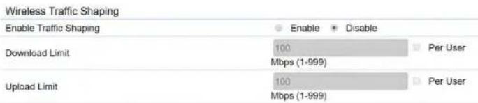
Enable Traffic Shaping: Default is disable. You may check this option to enable Wireless Traffic Shaping per SSID.
Download Limit: Specifies the wireless transmission speed used for downloading.
Upload Limit: Specifies the wireless transmission sp used for uploading.
Per User: Check this option to enable wireless tra shaping per user function. This function allows users to limit the maximum download / upload bandwidth for each client devices on this SSID.
FastRoaming
Enable the function to serve mobile client devices that roam from Access Point to Access Point. Some applications running on Client devices require fast re-association when they roam to a different Access Point
Please enter the settings of the SSID and initialize the Security mode to WPA enterprise, as well as to set the Radius Server firstly. Users can enable the Fast Roaming and implement the advanced search.
Please also set the same enterprise Encryption under the same SSID on other Access Points and enable the Fast Roaming. When the configuration is realized on different Access Point, the mobile client devices can run the voice service and require seamless roaming to prevent delay in conversation from Access Point to Access Point.

Guest Network Settings
Adding a guest network allows visitors to use the Internet without giving out your office or company wireless security key. You can add a guest network to wireless network in the 2.4 GHz b/g/n and 5 GHz ac/a/n frequencies.
the addresses by the DHCP server.
Ending IP Address: The last IP Address in the range of each addresses assigned by the DHCP server.
| Guest Network Settings | |||||
| Enable | SSID | Edit | Security | Suppressed SSID | Station Separation |
| EnGenius-2.4GHz_GuestNet | Edit | None | ✓ | ||
| EnGenius-5GHz_GuestNetw | Edit | None | ✓ | ||
| Manual IP Settings | |||||
| - IP Address | 192.168.200.1 | ||||
| - Subnet Mask | 255.255.255.0 | ||||
| Automatic DHCP Server Settings | |||||
| - Starting IP Address | 192.168.200.100 | ||||
| - Ending IP Address | 192.168.200.200 | ||||
| - WINS Server IP | 0.0.0.0 | ||||
SSID: Specifies the SSID for the current profile.
Suppressed SSID: Check this option to hide the SSID from clients. If checked, the SSID will not appear in the site survey.
Station Separation: Click the appropriate radio button to allow or prevent communication between client devices.
IP Address: The IP Address of this device.
Subnet Mask: The IP Subnet mask of this device.
Starting IP Address: The first IP Address in the range of
Chapter 8
Management

Management VLAN Settings
This page allows you to assign a VLAN tag to packets sent over the network. A VLAN is a group of computers on a network whose software has been configured so that they behave as if they were on a separate Local Area Network (LAN). Computers on VLAN do not have to be physically located next to one another on the LAN.
Note: Only applicable in Access Point.
DHCP server supports the reconfigured VLAN ID and then reconnect to this AP using the new IP address.
Management VLAN Settings
Status
Enable * Disable 4094
Caution: If you encounter disconnection issue during the configuration process, verify that the switch and the DHCP server can support the new VLAN ID and then connect to the new IP address.
Management VLAN: If your network includes VLANs, you can enable Management VLAN ID for packets passing through the Access Point with a tag.
Save: Click Save to confirm the changes or Cancel to cancel and return to previous settings.
Note: If you reconfigure the Management VLAN ID, you may lose your connection to this AP. Verify that the
Advanced Settings
SNMP Settings
This page allows you to assign the Contact Details, Location, Community Name, and Trap Settings for a Simple Network Management Protocol (SNMP). SNMP is a networking management protocol used to monitor network attached devices. SNMP allows messages (called protocol data units) to be sent to various parts of the network. Upon receiving these messages, SNMP compatible devices (called ag returns the data stored in their Management Information Bases.
SNMP Settings
| Status | Enable Disable | |
| Contact | ||
| Location | ||
| Community Name (Read Only) | public | |
| Community Name (Read Write) | private | |
| Trap Destination | ||
| - Port | 162 | |
| - IP Address | ||
| - Community Name | public | |
| SNMPv3 Settings | ||
| - Status | Enable Disable | |
| - Username | admin | (1-31 Characters) |
| - Authorized Protocol | MD5 | |
| - Authorized Key | 12345678 | (8-32 Characters) |
| - Private Protocol | DES | |
| - Private Key | 12345678 | (8-32 Characters) |
| - Engine ID | ||
SNMP Enable/Disable: Enables or disables the SNMP feature.
Contact: Specifies the contact details of the device.
Location: Specifies the location of the device.
Community Name (Read Only): Specifies the password for the SNMP community for read only access.
Community Name (Read/Write): Specifies the password for the SNMP community with read/write access.
Trap Destination Address: Specifies the IP address of the computer that will receive the SNMP traps.
Trap Destination Community Name: Specifies the password for the SNMP trap community.
SNMPv3: Enables or disables the SNMPv3 feature.
User Name: Specifies the username for SNMPv3.
Auth Protocol: Selects the authentication protocol type; MDS or SHA.
Auth Key: Specifies the authentication key.
Priv Protocol: Selects the privacy protocol type: DES.
Priv Key: Specifies the privacy key for privacy.
Engine ID: Specifies the engine ID for SNMPv3.
Apply Save: Click Apply Save to apply the changes.
CLI Settings
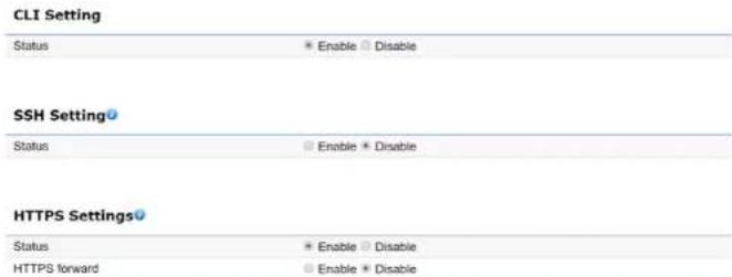
CLI: The Command Line Interface (CLI) allows you to type commands instead of choosing them from a menu or selecting an icon.
SSH: Enable Secure Shell (SSH) to make secure, encrypted connections in the network. Secure Shell is a network protocol that allows data to be exchanged using a secure channel between two network devices.
HTTPS: Enable HTTPS to transfer and display web content securely. The Hypertext Transfer Protocol over SSL (Secure Socket Layer) is a TCP/IP protocol used by web servers to transfer and display web content securely.
Email Alert
You can use the Email Alert feature to send messag to the configured email address when particular syster events occur.
Note: Do NOT use your personal email address as it can unnecessarily expose your personal email login credentials. Use a separate email account made for this feature instead
![Email Alert Status Enable - From To - Subject [Email-Agent]ENS620EXT[88.1] Email Account - Username Password SMTP Server Port: 25 - Security Mode None Send Test Mail Apply Apply saved settings to take effect](/content/2026/05/795198/images/be762c7d0c9ae34427a7346e698f073a8a44ab94a3c0838c48b96c14bb49b45c.jpg)
Status: Enable this function for further settings.
From: Enter the email address to show the sender of the email.
To: Enter the address to receive email alerts.
Subject: Enter the text to appear in the email subject line.
Username: Enter the username for the email account that will be used to send emails.
Password: Enter the password for the email account that will be used to send emails.
SMTP Server: Enter the IP address or hostname of the outgoing SMTP server.
Port: Enter the SMTP port number to use for outbound emails.
Time Zone
Time Setting
This page allows you to set the internal clock of the AP.
Date and Time Settings
| Manually Set Date and Time | ||
| Date: 2016 / 06 / 16 | ||
| Time: 07 : 21 (24-Hour) | ||
| Synchronize with PC | ||
| Automatically Get Date and Time | ||
| NTP Server: pool.ntp.org |
Time Zone
| Time Zone: UTC+00:00 Gambia, Liberia, Morocco | ||||
| Enable Daylight Saving | ||||
| Start: January 1st Sun 00:00 | ||||
| End: January 1st Mon 00:00 |
Apply
Apply saved settings to take effect
Manually Set Date and Time: Manually specify the date and time.
Synchronize with PC: Click this button to synchronize Date and time of this AP with the PC.
Automatically Get Date and Time: Select
Automatically Get Date and Time and check whether you wish to enter the IP address of an NTP server or use the default NTP server to have the internal clock set automatically.
Time Zone: Choose a time zone to implement the service for this AP.
Enable Daylight Saving: Check whether daylight savings applies to your area.
Start: Select the day, month, and time when daylight savings time starts.
Enable Daylight Saving: Select the day, month, and time when daylight savings times ends.
Auto Reboot Settings
You can specify how often you wish to reboot the AP.
Auto Reboot Setting
| Status | Enable Disable | |||||||
| Timer | Sunday | Monday | Tuesday | Wednesday | Thursday | Friday | Saturday | |
| 0 | : | 0 | ||||||
Auto Reboot Setting: Enables or disables the Auto Reboot function.
Timer: Select the day and enter the time you would like to reboot automatically.
Save: Click Save to apply the changes.
Wi-Fi Scheduler
The Wi-Fi Scheduler can be created for use in enforcing rules. For example, if you wish to restrict web Mon-Fri from 3pm to 8pm, you could create a schedule selecting Mon, Tue, Wed, Thu and Fri while entering a Start time of 3pm and End Time of 8pm to limit access to these times.
| Wi-Fi Scheduler | |||
| Status | ● Enable * DisableNOTE: Please assure that the Time Zone Settings is synced with your local time when enabling the Wi-Fi Scheduler | ||
| Wireless Radio | 2.4GHz | * | |
| SSID Selection | EnGenius330052_1-2.4GHz | * | |
| Schedule Templates | Choose a template | * | |
| Schedule Table | Day | Available | Duration |
| Sunday | available | 00 : 00 ~ 24 : 00 | |
| Monday | available | 00 : 00 ~ 24 : 00 | |
| Tuesday | available | 00 : 00 ~ 24 : 00 | |
| Wednesday | available | 00 : 00 ~ 24 : 00 | |
| Thursday | available | 00 : 00 ~ 24 : 00 | |
| Friday | available | 00 : 00 ~ 24 : 00 | |
| Saturday | available | 00 : 00 ~ 24 : 00 | |
Status: Enables or disables the Wi-Fi scheduler function.
Wireless Radio: Select 2.4 GHz or 5 GHz from the drop-down list for the preferred band type.
SSID Selection: Select a SSID from the drop-down list.
Schedule Templates: Select a schedule template from the access-down list.
Day(s): Place a checkmark in the boxes for the desired days or select the All Week radio button to select all seven days of the week.
Duration: The Start Time is entered in two fields. The first box is for hours and the second box is for minutes. The End Time is entered in the same format as the Start time.
Tools
Ping Test Parameters
This page allows you to analyze the connection quality of the AP and trace the routing table to a target in the network.
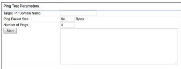

Target IP: Enter the IP address you would like to search.
Ping Packet Size: Enter the packet size of each ping.
Number of Pings: Enter the number of times you wish to ping.
Start Ping: Click Start Ping to begin pinging the target device (via IP).
Traceroute Target: Enter the IP address or domain name you wish to trace.
Start Traceroute: Click Start Traceroute to begin the trace route operation.
Speed Test Parameters / LED Control
This page allows you to implement speed test to realize the throughput of a target DUT.
Speed Test Parameters
| Target IP / Domain Name | ||
| Time Period | 20 | Sec |
| Check Interval | 5 | Sec |
| IPv4Port | 5001 | |
| IPv6Port | 5002 | |
| Start | ||
Target IP / Domain Name: Enter an IP address or domain name you wish to impelement a speed test for realizing the variance on wireless speed.
Time Period: Enter the time in seconds that you would like the test to implement for and in how many intervals.
IPv4/IPv6 Port: This Access Points uses IPv4 5001 IPv6 5002 port for the speed test.
Start: Click start to implement speed test.
LED Control
Control LED on/off for Power, LAN interface, or 2.4 GHz/5 GHz WLAN interface.
LED Control
| Power | ● Enable ○ Disable |
| LAN | ● Enable ○ Disable |
| WLAN-2.4GHz | ● Enable ○ Disable |
| WLAN-5GHz | ● Enable ○ Disable |
| Apply | Apply saved settings to take effect |
Power: Enables or disables the Power LED indicator.
LAN: Enables or disables the LAN LED indicator.
WLAN-2.4 GHz: Enables or disables the WLAN-2.4 GHz LED indicator. and
WLAN-5 GHz: Enables or disables the WLAN-5 GHz LED indicator.
Device Discovery
This page allows you to discover devices from network for Operation Mode, IP Address, System MAC Address and Firmware version.
Device Discovery
| Device Name | Operation Mode | IP Address | System MAC Address | Firmware Version |
| Scan |
Account
This page allows you to change the AP username and password. By default, the username is: admin and password is: admin. The password can contain from 0 to 12 alphanumeric characters and is case sensitive.
Account Settings
Account Settings
| Administrator Username | |
| Current Password | |
| New Password | |
| Verify Password |
Administrator Username: Enter a new username for logging in to the New Name entry box.
Current Password: Enter the old password for logging in to the Old Password entry box.
New Password: Enter the new password for logging in to the New Password entry box.
Verify Password: Re-enter the new password in the Confirm Password entry box for confirmation.
Apply: Click Apply to apply the changes.
Firmware
Firmware Upgrade
the This page allows you to upgrade the firmware of the AP.
Firmware Upgrade
Current Firmware Version:1.0.0
Select the new firmware from your hard disk.

To Perform the Firmware Upgrade:
-
Click the Choose File button and navigate the OS file system to the location of the upgrade file.
-
Select the upgrade file. The name of the file will appear in the Upgrade File field.
-
Click the Upload button to commence the firmware upgrade.
Note: The device is unavailable during the Firmware upgrade process and must restart when the upgrade is completed. Any connections to or through the device will be lost.
Backup/Restore
This page allows you to save the current device configurations. When you save your configurations, you also can reload the saved configurations into the device through the Restore Saved Settings from a file section. If extreme problems occur, or if you have set the AP incorrectly, you can use the Reset button in the Revert to Factory Default Settings section to restore all the configurations of the AP to the original default settings.
Backup Setting: Click Export to save the current configured settings.
Restore New Setting: To restore settings that have been previously backed up, click Browse, select the file, and click Restore.
Restore to Default: Click Reset button to restore the AP to its factory default settings.
Backup/Restore Settings
| Factory Setting | ||
| - Backup Setting | Export | |
| - Restore New Setting | 選擇檔案 未選擇任何檔案 | Import |
| - Reset to Default | Reset | |
| User Setting | ||
| - Back Up Setting as Default | Backup | |
| - Restore to User Default | Restore | |
| - Caution: Please write down your account number and password before saving. The user settings will now become the new default settings at the next successful login. | ||
User Setting
The function allows you to backup the current device configurations into the AP as the default value. If extreme problems occur, or if you have set the incorrectly, you can push the Reset button to revert all the configurations of the AP to the user default.
Back Up Setting as Default: Click Backup to backup the user settings you would like to the device's memory for the default settings.
- Restore to User Default: Click Restore to restore user settings to the factory standard settings.
Note1: After setting the current settings as the default, you should click the Restore to Default on the web interface for reverting the settings into the factory default instead of pushing the reset button.
Note2: Please write down your account and password before saving. The user settings will now become the new default settings at the next successful login.
Log
System Log
The AP automatically logs (records) events of point interest in its internal memory. To view the logged information, click the Log link under the System Manager menu. If there is not enough internal memory to log all events, older events are deleted from the log. When powered down or rebooted, the log will be cleared.
System Log
![Status Enable Disable Log type ALL Refresh Clear Tue Jul 12 12:20:01 2016 cron.info crond[4186] crond: USER root pid 7926 cmd /etc/init.d:/systime start rtp_ Tue Jul 12 12:18:01 2016 cron.info crond[4186] crond: USER root pid 7915 cmd /etc/init.d:/systime start rtp_ Tue Jul 12 12:16:01 2016 cron.info crond[4186] crond: USER root pid 7904 cmd /etc/init.d:/systime start rtp_ Tue Jul 12 12:14:01 2016 cron.info crond[4186] crond: USER root pid 7893 cmd /etc/init.d:/systime start rtp_ Tue Jul 12 12:12:01 2016 cron.info crond[4186] crond: USER root pid 7882 cmd /etc/init.d:/systime start rtp_ Tue Jul 12 12:10:01 2016 cron.info crond[4186] crond: USER root pid 6070 cmd /etc/init.d:/systime start rtp_ Tue Jul 12 12:08:01 2016 cron.info crond[4186] crond: USER root pid 6045 cmd /etc/init.d:/systime start rtp_ Tue Jul 12 12/06:01 2016 cron.info crond[4186] crond: USER root pid 6034 cmd /etc/init.d:/systime start rtp_ Tue Jul 12 12/04:01 2016 cron.info crond[4186] crond: USER root pid 6023 cmd /etc/init.d:/systime start rtp_](/content/2026/05/795198/images/ccdc980132ec388d7528779507f49a096e6f09a1102104099cb4dc83c7f43b53.jpg)
Status: Enable/Disable this function.

Log type: You may choose one of log types to display logs in the following window. The default log types is All.

Remote Log
This page allows you to setup the Remote Log functions for this AP.
Remote Log: Enable/Disable this function.
Log Server IP Address: Enter the IP address of the log server.
Apply: Click Apply to apply the changes.
Logout
Logout: Click Logout in Management menu to logout.
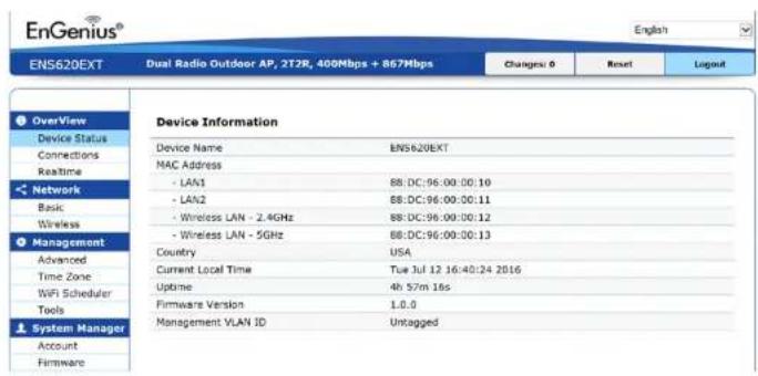
Please confirm again to logout the system or not.

Reset
In some circumstances, it may be required to force the device to reboot. Click on Reset to reboot the AP.
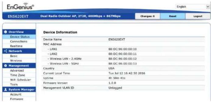
Once you click reset button, you will see the options for reboot or restore this AP.
Reboot the device: Click it to reboot this device.
Restore to Factory Default: Click it to reset this device to factory default setting.
Restore to User Default: Click it to reset this device to user default settings. For realizing the setting method, you may refer page 65 and page 66.

Appendix

Appendix A
Federal Communication Commission Interference Statement
This equipment has been tested and found to comply with the limits for a Class B digital device, pursuant to Part 15 of the FCC Rules. These limits are designed to provide reasonable protection against harmful interference in a residential installation. This equipment generates, uses and can radiate radio frequency energy and, if not installed and used in accordance with the instructions, may cause harmful interference to radio communications. However, there is no guarantee that interference will not occur in a particular installation. If this equipment does cause harmful interference to radio or television reception, which can be determined by turning the equipment off and on, the user is encouraged to try to correct the interference by one of the following measures:
• Reorient or relocate the receiving antenna.
- Increase the separation between the equipment and receiver.
- Connect the equipment into an outlet on a circuit different from that to which the receiver is connected.
- Consult the dealer or an experienced radio/TV technician for help

FCC Caution:
Any changes or modifications not expressly approved by the party responsible for compliance could void the user's authority to operate this equipment.
This transmitter must not be co-located or operating in conjunction with any other antenna or transmitter.
Operations in the 5.15-5.25GHz band are restricted to indoor usage only.
IMPORTANT NOTE:
Radiation Exposure Statement
EWS357AP: This equipment complies with FCC radiation exposure limits set forth for an uncontrolled environment. This equipment should be installed and operated with minimum distance 20 cm between the radiator & your body.
EWS377AP: This equipment complies with FCC radiation exposure limits set forth for an uncontrolled environment. This equipment should be installed and operated with minimum distance 25 cm between the radiator & your body.
Appendix B - IC Interference Statement
Industry Canada Statement
This device complies with RSS-247 of the Industry Canada Rules. Operation is subject to the following two conditions: (1) This device may not cause harmful interference, and (2) this device must accept any interference received, including interference that may cause undesired operation.
(i) the device for operation in the band 5150-5250 MHz is only for indoor use to reduce the potential for harmful interference to co-channel mobile satellite systems;
(ii) high-power radars are allocated as primary users (i.e. priority users) of the bands 5250-5350 MHz and 5650-5850 MHz and that these radars could cause interference and/or damage to LE-LAN devices.
(iii) Users should also be advised that high-power radars are allocated as primary users (i.e. priority users) of the bands 5650-5850 MHz and that these radars could cause interference and/or damage to LE-LAN devices.

Avertissement:
EWS357AP: This equipment complies with IC radiation exposure limits set forth for an uncontrolled environment. This equipment should be installed and operated with a minimum distance of 20cm between the radiator & your body.
EWS377AP: This equipment complies with IC radiation exposure limits set forth for an uncontrolled environment. This equipment should be installed and operated with a minimum distance of 30cm between the radiator & your body.
Europe - EU Declaration of Conformity
This device complies with Directive 2014/53/EU issued by the Commission of the European Community.
- Declaration of Conformity
Please added certification standard in your user manual which depended on the test standards your device performed. or
- If the DoC should be a simplified version, please take below as reference –
Hereby, EnGenius Networks declares that the EWS357AP and EWS377AP are in compliance with Directive 2014/53/EU.
The full text of the EU declaration of conformity is available at the following internet address:
The frequency and maximum transmitted power in EU are listed as belows,
| Devices 2412 - 2472 MHz 5180 - 5240 MHz 5260 - 5230 MHz 5500 - 5700 MHz | |||
| EWS357AP 3.5dBi 4.5~4.6dBi NA NA | |||
| EWS377AP TBD TBD NA NA |
Importer: EnGenius Networks Europe B.V.
Importer Address: Fellenoord 180, 5611 ZB - Eindhoven, The Netherlands
Manufacturer : EnGenius Networks. Inc.
Manufacturer Address: No.500, Fusing 3rd Rd., Hwa-Ya Technology Park Kuei-Shan Dist., Taoyuan City, Taiwan (R.O.C.)
CE DoC Link: https://s3-ap-northeast-1.amazonaws.com/engrbu/wp-content/uploads/2019/05/20135812/CE_DoC-EWS357AP-
- IMPORTANT
- Table of Contents
- Chapter 1 Product Overview.... 4
- Chapter 2 Before You Begin....10
- Chapter 3 Configuring Your Access Point.... 18
- Chapter 4 Building a Wireless Network.... 20
- Chapter 5 Status....22
- Chapter 6 Network 27
- Chapter 7 2.4 GHz/5 GHz Wireless.... 30
- Chapter 8 Management ...... 40
- Appendix.... 56
- Chapter 1
- Product Overview
- Introduction
- Key Features - EWS357AP nad EWS377AP
- System Requirements
- Package Contents
- Technical Specifications (EWS357AP/EWS377AP)
- Antenna
- Physical Interfaces
- LED Indicators
- Power Requirements
- Operation Modes
- Exquisite RF Management
- Optimize Performance
- Easy to Management
- Comprehensive Protection
- Security
- Physical/Environment Conditions
- Physical Interface (EWS357AP)
- Physical Interface (EWS377AP)
- Chapter 2
- Before You Begin
- Computer Settings
- Windows XP/Windows 7/Windows 8/Windows 10
- 1a. Click the Start button and open the Control Panel
- Network Connections
- Apple Mac OS X
- Hardware Installation
- Mounting the AP
- Ceiling Mount an Access Point
- Wall Mount an Access Point
- Chapter 3
- Configuring Your Access Point
- Default Settings
- Web Configuration
- Chapter 4
- Building a Wireless Network
- Access Point Mode
- Chapter 5
- Status
- Overview
- Save Changes
- Device Status
- Connections Realtime
- GHz/5 GHz Connection List
- GHz/5 GHz WDS Link List
- Realtime
- Chapter 6 Network
- Basic
- IPv4/IPv6 Settings
- Spanning Tree Protocol (STP) Settings
- Chapter 7
- GHz & 5 GHz Wireless
- Wireless
- Wireless Settings
- GHz/5 GHz Wireless Network
- GHz/5 GHz SSID Profile
- Wireless Security
- Wireless MAC Filtering
- Wireless Advanced
- Wireless Traffic Shaping
- FastRoaming
- Guest Network Settings
- Chapter 8
- Management
- Management VLAN Settings
- Advanced Settings
- SNMP Settings
- CLI Settings
- Email Alert
- Time Zone
- Time Setting
- Automatically Get Date and Time: Select
- Auto Reboot Settings
- Wi-Fi Scheduler
- Tools
- Ping Test Parameters
- Speed Test Parameters / LED Control
- LED Control
- Device Discovery
- Account
- Account Settings
- Firmware
- Firmware Upgrade
- To Perform the Firmware Upgrade:
- Backup/Restore
- User Setting
- Log
- System Log
- Remote Log
- Logout
- Reset
- Appendix
- Appendix A
- Federal Communication Commission Interference Statement
- FCC Caution:
- IMPORTANT NOTE:
- Radiation Exposure Statement
- Appendix B - IC Interference Statement
- Industry Canada Statement
- Avertissement:
- Europe - EU Declaration of Conformity
Brand : ENGENIUS
Model : EWS357AP
Category : Access Point